

Page 1
SPLIT-TYPE, HEAT PUMP AIR CONDITIONERS
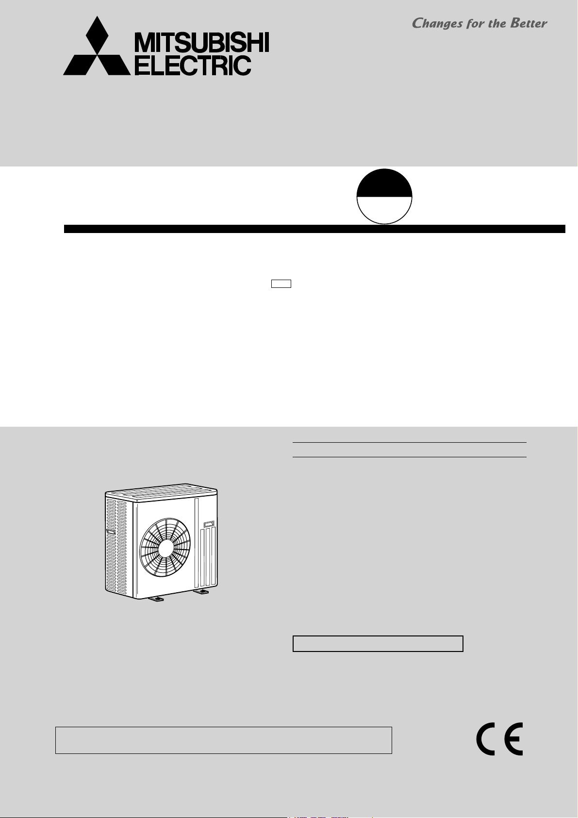
OUTDOOR UNIT
SERVICE MANUAL
Wireless type
Model
MUH-GD80VB -
E1
CONTENTS
HFC
utilized
R410A
Indoor unit service manual
MSH-GD•VB Series (OBH513)
No. OBH514
1. TECHNICAL CHANGES ··································· 2
2. PART NAMES AND FUNCTIONS ····················· 2
3. SPECIFICATION ················································ 3
4. NOISE CRITERIA CURVES ······························ 3
5. OUTLINES AND DIMENSIONS ························ 4
6. WIRING DIAGRAM ············································ 4
7. REFRIGERANT SYSTEM DIAGRAM ··············· 5
8. PERFORMANCE CURVES ······························· 6
9. ACTUA TOR CONTROL ··································· 10
10. SERVICE FUNCTIONS ·····································11
11. TROUBLESHOOTING ······································ 11
12. DISASSEMBLY INSTRUCTIONS ···················· 18
PARTS CATALOG (OBB514)
NOTE:
RoHS compliant products have <G> mark on the spec name plate.
Page 2
1
TECHNICAL CHANGES
MUH-GD80VB -
1. New model
2
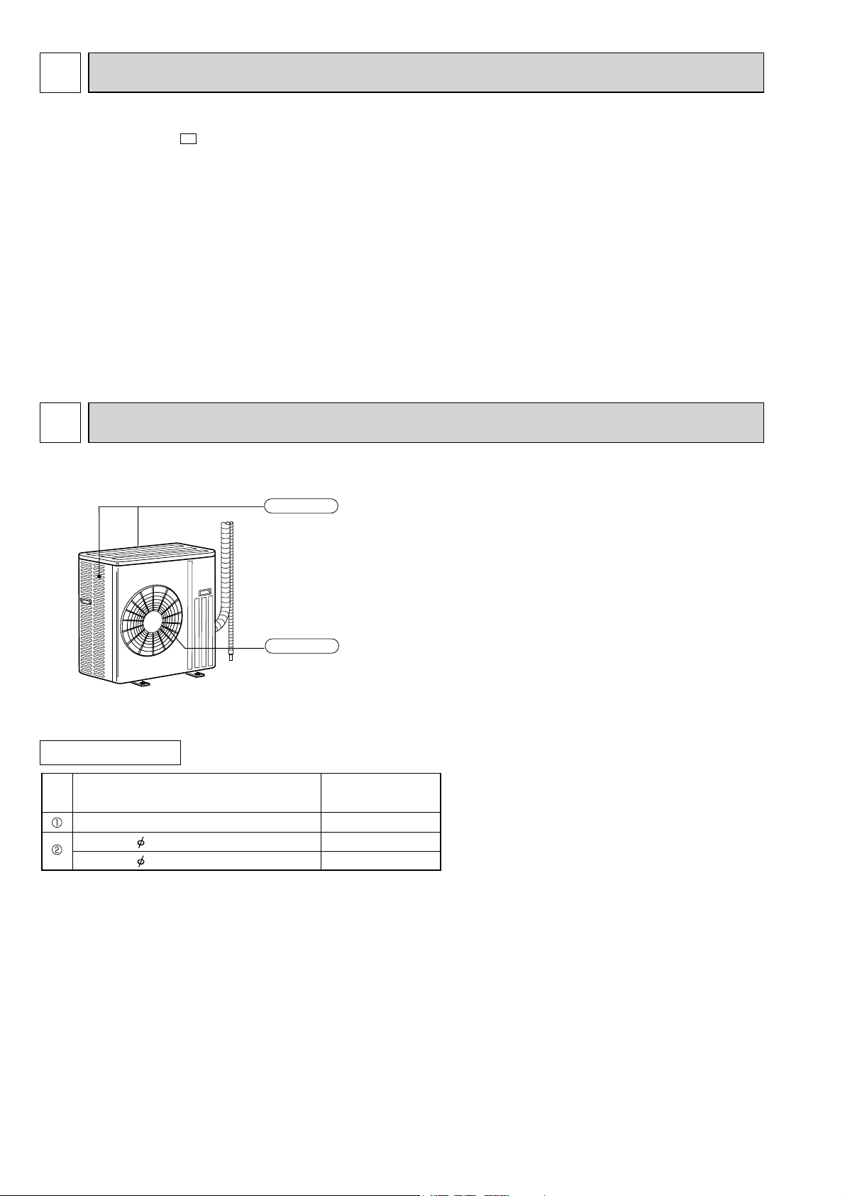
PART NAMES AND FUNCTIONS
MUH-GD80VB
E1
Air inlet
(back and side)
ACCESSORIES
Drain socket
Drain cap 33
Drain cap 16
Air outlet
MUH-GD80VB
1
2
—
2
Page 3
3
SPECIFICATION
Outdoor model MUH-GD80VB
Function Cooling Heating
Power supply
Single phase
230 V, 50 Hz
Capacity kW 8.0 9.4
Breaker capacity A 25
Running current (Total)
Power input (Total) W 3,320 3,580
data
Power factor (Total) % 98
Electrical
Starting current (Total)
Coeffi cient of performance (C.O.P) (Total)
A 14.76 15.90
A90
2.41 2.63
Model NN37VAAHT
Output W 2,500
Compressor
Compressor motor current
A 13.85 14.62
Model RA6V75-AD
Fan
Fan motor current A 0.57
motor
Dimensions W H
D mm 840 850 330
Weight kg 77
Dehumidifi cation /h 4.6
Air fl ow
(High/Low)
Sound level (High/Low)
Fan speed (High/Low)
Fan speed regulator 2
Special
remarks
Refrigerant fi lling
capacity (R410A)
/h 2,940/1,470
dB 55/53
rpm 805/435
kg 2.40
-
Refrigeration oil (Model) NEO 22
NOTE: Test conditions are based on ISO 5151.
Cooling: Indoor Dry-bulb temperature 27°C Wet-bulb temperature 19°C
Outdoor Dry-bulb temperature 35°C Wet-bulb temperature 24°C
Heating: Indoor Dry-bulb temperature 20°C Wet-bulb temperature 15.5°C
Outdoor Dry-bulb temperature 7°C Wet-bulb temperature 6°C
Indoor-Outdoor piping length: 5 m
4
MUH-GD80VB
Test conditions,
Cooling : Dry-bulb temperature 35 Wet-bulb temperature 24
Heating : Dry-bulb temperature 7 Wet-bulb temperature 6
90
80
70
60
50
40
30
20
OCTAVE BAND SOUND PRESSURE LEVEL, dB re 0.0002 MICRO BAR
10
NOISE CRITERIA CURVES
FAN SPEED
High
APPROXIMATE
THRESHOLD OF
HEARING FOR
CONTINUOUS
NOISE
63 125 250 500 1000 2000 4000 8000
BAND CENTER FREQUENCIES, Hz
SPL(dB(A)) LINE
55
OUTDOOR UNIT
1m
MICROPHONE
NC-70
NC-60
NC-50
NC-40
NC-30
NC-20
3
Page 4
5
OUTLINES AND DIMENSIONS
MUH-GD80VB
51
34
330
850
430
66
299
515
121
500
840
40
REQUIRED SPACE
100 mm or more
360
Open as a rule
80
500 mm or more if the back,
both sides and top are open
155
90
198
Open as a rule
500 mm or more if
the front and both
sides are open
100 mm or more
200 mm or more if
there are obstacles
to both sides
350 mm or more
Service panel
Liquid refrigerant
pipe joint
Refrigerant pipe
(flared) 9.52
30º
35º
Gas refrigerant
pipe joint
Refrigerant pipe
(flared) 15.88
Unit: mm
6
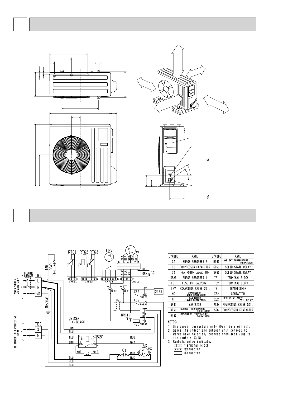
WIRING DIAGRAM
MUH-GD80VB
4
Page 5
7
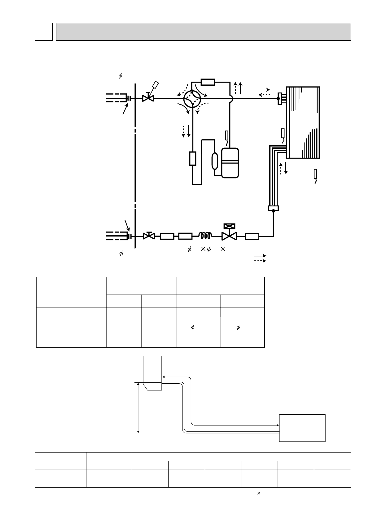
REFRIGERANT SYSTEM DIAGRAM
MUH-GD80VB
Refrigerant pipe 15.88
(with heat insulator)
Stop valve
(with service port)
Flared connection
Flared connection
Receiver
Stop valve
Refrigerant pipe 9.52
(with heat insulator)
MAX. REFRIGERANT PIPING LENGTH
4-way valve
Muffler
Strainer
#100
Capillary tube
3.6 2.4 50
Muffler
#100
Discharge
temperature
thermistor
RT62
Compressor
LEV
Defrost
thermistor
RT61
Strainer
#100
Unit: mm
Outdoor
heat
exchanger
Ambient
temperature
thermistor
RT63
R.V. coil
heating ON
cooling OFF
Refrigerant flow in cooling
Refrigerant flow in heating
Model
MUH-GD80VB
Refrigerant piping: m
Max. length AMax. height
30
B
15
Piping size O.D: mm
Gas
15.88
MAX. HEIGHT DIFFERENCE
Indoor
unit
Max. Height
difference
B
ADDITIONAL REFRIGERANT CHARGE (R410A: g)
Model
Outdoor unit
precharged
Refrigerant piping length (one way)
Liquid
Max. length
A
15 m10 m7 m
9.52
20 m
Outdoor unit
25 m 30 m
MUH-GD80VB
2,400
0 165 440 715 990 1,265
Calculation: Xg = 55 g/m (Refrigerant piping length (m) - 7)
5
Page 6
8
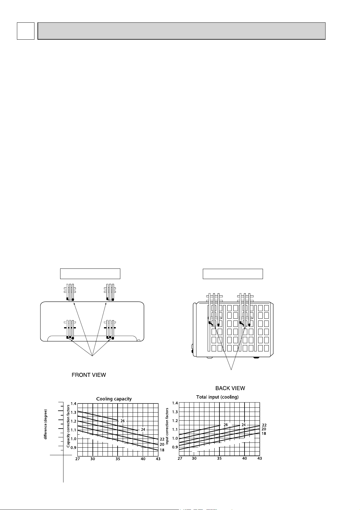
PERFORMANCE CURVES
MUH-GD80VB
The standard specifications apply only to the operation of the air conditioner under normal conditions, since operating conditions vary according to the areas where these units are installed. The following information has been provided to clarify the
operating characteristics of the air conditioner under the conditions indicated by the performance curve.
(1) GUARANTEED VOLTAGE
198 ~ 264 V, 50 Hz
(2) AIR FLOW
Air flow should be set at MAX.
(3) MAIN READINGS
(1) Indoor intake air wet-bulb temperature: °CWB
(2) Indoor outlet air wet-bulb temperature: °CWB
(3) Outdoor intake air dry-bulb temperature: °CDB
(4) Total input: W
(5) Indoor intake air dry-bulb temperature: °CDB
(6) Outdoor intake air wet-bulb temperature: °CWB
(7) Total input: W
Indoor air wet/dry-bulb temperature difference on the left side of the following chart shows the difference between the
indoor intake air wet/dry-bulb temperature and the indoor outlet air wet/dry-bulb temperature for your reference at service.
How to measure the indoor air wet-bulb/dry-bulb temperature difference
1. Attach at least 2 sets of wet and dry-bulb thermometers to the indoor air intake as shown in the figure, and at least 2 sets
of wet and dry-bulb thermometers to the indoor air outlet. The thermometers must be attached to the position where air
speed is high.
2. Attach at least 2 sets of wet and dry-bulb thermometers to the outdoor air intake.
Cover the thermometers to prevent direct rays of the sun.
3. Check that the air filter is cleaned.
4. Open windows and doors of room.
5. Press the EMERGENCY OPERATION switch once (twice) to start the EMERGENCY COOL (HEAT) MODE.
6. When system stabilizes after more than 15 minutes, measure temperature and take an average temperature.
7. 10 minutes later, measure temperature again and check that the temperature does not change.
}
}
Cooling
Heating
INDOOR UNIT
Wet and dry-bulb
thermometers
19.2
17.4
15.6
13.9
12.4
10.8
Indoor air Wet-bulb temperature
OUTDOOR UNIT
Wet and dry-bulb
thermometers
Indoor intake air Wet-bulb temperature (°C)
Indoor intake air Wet-bulb temperature (°C)
Outdoor intake air Dry-bulb temperature (°C) Outdoor intake air Dry-bulb temperature (°C)
MUH-GD80VB
6
Page 7

38.4
35.5
32.5
29.6
26.6
23.6
20.7
17.7
Indoor air Dry-bulb temperature
Indoor intake air Dry-bulb temperature (°C)
Indoor intake air Dry-bulb temperature (°C)
Outdoor intake air Wet-bulb temperature (°C)
Outdoor intake air Wet-bulb temperature (°C)
NOTE: The above curves are for the heating operation without any frost.
MUH-GD80VB
OUTDOOR LOW PRESSURE AND OUTDOOR UNIT CURRENT
COOL operation
Both indoor and outdoor unit are under the same temperature/humidity condition.
Dry-bulb temperature
20
25
30
Air flow should be set at MAX.
The unit of pressure has been changed to MPa on the international system of units (SI unit system).
The conversion factor is: 1(MPa [Gauge]) = 10.2 (kgf/ [Gauge])
(kgf/ [Gauge])(MPa[Gauge])
11
11
10
10
9
9
8
8
7
7
Outdoor low pressure
6
5
6
5
18
15 20
Ambient temperature (˚C)
Ambient humidity (%)
Relative humidity(%)
50
60
70
MUH-GD80VB
50
25
60
30 35
70 (%)
230 V
32
MUH-GD80VB
16
15
14
13
12
Outdoor unit current(A)
11
10
18
15 20
50
Ambient temperature (˚C)
Ambient humidity (%)
25
60
230 V
30 35
32
70 (%)
HEAT operation
Condition indoor: Dry bulb temperature 20.0°C
Wet bulb temperature 14.5°C
Outdoor: Dry bulb temperature 7,15, 20°C
Wet bulb temperature 6,12, 14.5°C
MUH-GD80VB
20
230 V
19
18
17
Outdoor unit current(A)
16
5 10152025
7
21
Ambient temperature (˚C)
7
Page 8

PERFORMANCE DATA COOL operation
MSH-GD80VB: MUH-GD80VB (230V)
CAPACITY : 8.0(kW) SHF : 0.62 INPUT : 3320(W)
OUTDOOR DB(°C)
INDOOR INDOOR
DB(°C) WB(°C)
21 18 9.40 4.14 0.44 2656 9.00 3.96 0.44 2789 8.64 3.80 0.44 2922 8.32 3.66 0.44 3054
21 20 9.80 3.14 0.32 2789 9.40 3.01 0.32 2955 9.12 2.92 0.32 3021 8.80 2.82 0.32 3154
22 18 9.40 4.51 0.48 2656 9.00 4.32 0.48 2789 8.64 4.15 0.48 2922 8.32 3.99 0.48 3054
22 20 9.80 3.53 0.36 2789 9.40 3.38 0.36 2955 9.12 3.28 0.36 3021 8.80 3.17 0.36 3154
22 22 10.20 2.45 0.24 2888 9.84 2.36 0.24 3071 9.60 2.30 0.24 3154 9.20 2.21 0.24 3287
23 18 9.40 4.89 0.52 2656 9.00 4.68 0.52 2789 8.64 4.49 0.52 2922 8.32 4.33 0.52 3054
23 20 9.80 3.92 0.40 2789 9.40 3.76 0.40 2955 9.12 3.65 0.40 3021 8.80 3.52 0.40 3154
23 22 10.20 2.86 0.28 2888 9.84 2.76 0.28 3071 9.60 2.69 0.28 3154 9.20 2.58 0.28 3287
24 18 9.40 5.26 0.56 2656 9.00 5.04 0.56 2789 8.64 4.84 0.56 2922 8.32 4.66 0.56 3054
24 20 9.80 4.31 0.44 2789 9.40 4.14 0.44 2955 9.12 4.01 0.44 3021 8.80 3.87 0.44 3154
24 22 10.20 3.26 0.32 2888 9.84 3.15 0.32 3071 9.60 3.07 0.32 3154 9.20 2.94 0.32 3287
24 24 10.72 2.14 0.20 3021 10.32 2.06 0.20 3187 10.08 2.02 0.20 3287 9.76 1.95 0.20 3453
25 18 9.40 5.64 0.60 2656 9.00 5.40 0.60 2789 8.64 5.18 0.60 2922 8.32 4.99 0.60 3054
25 20 9.80 4.70 0.48 2789 9.40 4.51 0.48 2955 9.12 4.38 0.48 3021 8.80 4.22 0.48 3154
25 22 10.20 3.67 0.36 2888 9.84 3.54 0.36 3071 9.60 3.46 0.36 3154 9.20 3.31 0.36 3287
25 24 10.72 2.57 0.24 3021 10.32 2.48 0.24 3187 10.08 2.42 0.24 3287 9.76 2.34 0.24 3453
26 18 9.40 6.02 0.64 2656 9.00 5.76 0.64 2789 8.64 5.53 0.64 2922 8.32 5.32 0.64 3054
26 20 9.80 5.10 0.52 2789 9.40 4.89 0.52 2955 9.12 4.74 0.52 3021 8.80 4.58 0.52 3154
26 22 10.20 4.08 0.40 2888 9.84 3.94 0.40 3071 9.60 3.84 0.40 3154 9.20 3.68 0.40 3287
26 24 10.72 3.00 0.28 3021 10.32 2.89 0.28 3187 10.08 2.82 0.28 3287 9.76 2.73 0.28 3453
26 26 11.04 1.77 0.16 3187 10.72 1.72 0.16 3353 10.56 1.69 0.16 3453 10.24 1.64 0.16 3552
27 18 9.40 6.39 0.68 2656 9.00 6.12 0.68 2789 8.64 5.88 0.68 2922 8.32 5.66 0.68 3054
27 20 9.80 5.49 0.56 2789 9.40 5.26 0.56 2955 9.12 5.11 0.56 3021 8.80 4.93 0.56 3154
27 22 10.20 4.49 0.44 2888 9.84 4.33 0.44 3071 9.60 4.22 0.44 3154 9.20 4.05 0.44 3287
27 24 10.72 3.43 0.32 3021 10.32 3.30 0.32 3187 10.08 3.23 0.32 3287 9.76 3.12 0.32 3453
27 26 11.04 2.21 0.20 3187 10.72 2.14 0.20 3353 10.56 2.11 0.20 3453 10.24 2.05 0.20 3552
28 18 9.40 6.77 0.72 2656 9.00 6.48 0.72 2789 8.64 6.22 0.72 2922 8.32 5.99 0.72 3054
28 20 9.80 5.88 0.60 2789 9.40 5.64 0.60 2955 9.12 5.47 0.60 3021 8.80 5.28 0.60 3154
28 22 10.20 4.90 0.48 2888 9.84 4.72 0.48 3071 9.60 4.61 0.48 3154 9.20 4.42 0.48 3287
28 24 10.72 3.86 0.36 3021 10.32 3.72 0.36 3187 10.08 3.63 0.36 3287 9.76 3.51 0.36 3453
28 26 11.04 2.65 0.24 3187 10.72 2.57 0.24 3353 10.56 2.53 0.24 3453 10.24 2.46 0.24 3552
29 18 9.40 7.14 0.76 2656 9.00 6.84 0.76 2789 8.64 6.57 0.76 2922 8.32 6.32 0.76 3054
29 20 9.80 6.27 0.64 2789 9.40 6.02 0.64 2955 9.12 5.84 0.64 3021 8.80 5.63 0.64 3154
29 22 10.20 5.30 0.52 2888 9.84 5.12 0.52 3071 9.60 4.99 0.52 3154 9.20 4.78 0.52 3287
29 24 10.72 4.29 0.40 3021 10.32 4.13 0.40 3187 10.08 4.03 0.40 3287 9.76 3.90 0.40 3453
29 26 11.04 3.09 0.28 3187 10.72 3.00 0.28 3353 10.56 2.96 0.28 3453 10.24 2.87 0.28 3552
30 18 9.40 7.52 0.80 2656 9.00 7.20 0.80 2789 8.64 6.91 0.80 2922 8.32 6.66 0.80 3054
30 20 9.80 6.66 0.68 2789 9.40 6.39 0.68 2955 9.12 6.20 0.68 3021 8.80 5.98 0.68 3154
30 22 10.20 5.71 0.56 2888 9.84 5.51 0.56 3071 9.60 5.38 0.56 3154 9.20 5.15 0.56 3287
30 24 10.72 4.72 0.44 3021 10.32 4.54 0.44 3187 10.08 4.44 0.44 3287 9.76 4.29 0.44 3453
30 26 11.04 3.53 0.32 3187 10.72 3.43 0.32 3353 10.56 3.38 0.32 3453 10.24 3.28 0.32 3552
31 18 9.40 7.90 0.84 2656 9.00 7.56 0.84 2789 8.64 7.26 0.84 2922 8.32 6.99 0.84 3054
31 20 9.80 7.06 0.72 2789 9.40 6.77 0.72 2955 9.12 6.57 0.72 3021 8.80 6.34 0.72 3154
31 22 10.20 6.12 0.60 2888 9.84 5.90 0.60 3071 9.60 5.76 0.60 3154 9.20 5.52 0.60 3287
31 24 10.72 5.15 0.48 3021 10.32 4.95 0.48 3187 10.08 4.84 0.48 3287 9.76 4.68 0.48 3453
31 26 11.04 3.97 0.36 3187 10.72 3.86 0.36 3353 10.56 3.80 0.36 3453 10.24 3.69 0.36 3552
32 18 9.40 8.27 0.88 2656 9.00 7.92 0.88 2789 8.64 7.60 0.88 2922 8.32 7.32 0.88 3054
32 20 9.80 7.45 0.76 2789 9.40 7.14 0.76 2955 9.12 6.93 0.76 3021 8.80 6.69 0.76 3154
32 22 10.20 6.53 0.64 2888 9.84 6.30 0.64 3071 9.60 6.14 0.64 3154 9.20 5.89 0.64 3287
32 24 10.72 5.57 0.52 3021 10.32 5.37 0.52 3187 10.08 5.24 0.52 3287 9.76 5.08 0.52 3453
32 26 11.04 4.42 0.40 3187 10.72 4.29 0.40 3353 10.56 4.22 0.40 3453 10.24 4.10 0.40 3552
Q SHC SHF INPUT Q SHC SHF INPUT Q SHC SHF INPUT Q SHC SHF INPUT
NOTE Q : Total capacity (kW) SHF : Sensible heat factor DB : Dry-bulb temperature
SHC : Sensible heat capacity (kW) INPUT : Total power input (W) WB : Wet-bulb temperature
21 25 27 30
8
Page 9

PERFORMANCE DATA COOL operation
MSH-GD80VB: MUH-GD80VB (230V)
CAPACITY : 8.0(kW) SHF : 0.62 INPUT : 3320(W)
INDOOR INDOOR
DB(°C) WB(°C)
21 18 7.84 3.45 0.44 3254 7.20 3.17 0.44 3453 6.92 3.04 0.44 3519
21 20 8.24 2.64 0.32 3386 7.68 2.46 0.32 3552 7.40 2.37 0.32 3652
22 18 7.84 3.76 0.48 3254 7.20 3.46 0.48 3453 6.92 3.32 0.48 3519
22 20 8.24 2.97 0.36 3386 7.68 2.76 0.36 3552 7.40 2.66 0.36 3652
22 22 8.72 2.09 0.24 3519 8.16 1.96 0.24 3718 7.88 1.89 0.24 3785
23 18 7.84 4.08 0.52 3254 7.20 3.74 0.52 3453 6.92 3.60 0.52 3519
23 20 8.24 3.30 0.40 3386 7.68 3.07 0.40 3552 7.40 2.96 0.40 3652
23 22 8.72 2.44 0.28 3519 8.16 2.28 0.28 3718 7.88 2.21 0.28 3785
24 18 7.84 4.39 0.56 3254 7.20 4.03 0.56 3453 6.92 3.88 0.56 3519
24 20 8.24 3.63 0.44 3386 7.68 3.38 0.44 3552 7.40 3.26 0.44 3652
24 22 8.72 2.79 0.32 3519 8.16 2.61 0.32 3718 7.88 2.52 0.32 3785
24 24 9.20 1.84 0.20 3652 8.64 1.73 0.20 3818 8.40 1.68 0.20 3901
25 18 7.84 4.70 0.60 3254 7.20 4.32 0.60 3453 6.92 4.15 0.60 3519
25 20 8.24 3.96 0.48 3386 7.68 3.69 0.48 3552 7.40 3.55 0.48 3652
25 22 8.72 3.14 0.36 3519 8.16 2.94 0.36 3718 7.88 2.84 0.36 3785
25 24 9.20 2.21 0.24 3652 8.64 2.07 0.24 3818 8.40 2.02 0.24 3901
26 18 7.84 5.02 0.64 3254 7.20 4.61 0.64 3453 6.92 4.43 0.64 3519
26 20 8.24 4.28 0.52 3386 7.68 3.99 0.52 3552 7.40 3.85 0.52 3652
26 22 8.72 3.49 0.40 3519 8.16 3.26 0.40 3718 7.88 3.15 0.40 3785
26 24 9.20 2.58 0.28 3652 8.64 2.42 0.28 3818 8.40 2.35 0.28 3901
26 26 9.68 1.55 0.16 3785 9.12 1.46 0.16 3951 8.84 1.41 0.16 4034
27 18 7.84 5.33 0.68 3254 7.20 4.90 0.68 3453 6.92 4.71 0.68 3519
27 20 8.24 4.61 0.56 3386 7.68 4.30 0.56 3552 7.40 4.14 0.56 3652
27 22 8.72 3.84 0.44 3519 8.16 3.59 0.44 3718 7.88 3.47 0.44 3785
27 24 9.20 2.94 0.32 3652 8.64 2.76 0.32 3818 8.40 2.69 0.32 3901
27 26 9.68 1.94 0.20 3785 9.12 1.82 0.20 3951 8.84 1.77 0.20 4034
28 18 7.84 5.64 0.72 3254 7.20 5.18 0.72 3453 6.92 4.98 0.72 3519
28 20 8.24 4.94 0.60 3386 7.68 4.61 0.60 3552 7.40 4.44 0.60 3652
28 22 8.72 4.19 0.48 3519 8.16 3.92 0.48 3718 7.88 3.78 0.48 3785
28 24 9.20 3.31 0.36 3652 8.64 3.11 0.36 3818 8.40 3.02 0.36 3901
28 26 9.68 2.32 0.24 3785 9.12 2.19 0.24 3951 8.84 2.12 0.24 4034
29 18 7.84 5.96 0.76 3254 7.20 5.47 0.76 3453 6.92 5.26 0.76 3519
29 20 8.24 5.27 0.64 3386 7.68 4.92 0.64 3552 7.40 4.74 0.64 3652
29 22 8.72 4.53 0.52 3519 8.16 4.24 0.52 3718 7.88 4.10 0.52 3785
29 24 9.20 3.68 0.40 3652 8.64 3.46 0.40 3818 8.40 3.36 0.40 3901
29 26 9.68 2.71 0.28 3785 9.12 2.55 0.28 3951 8.84 2.48 0.28 4034
30 18 7.84 6.27 0.80 3254 7.20 5.76 0.80 3453 6.92 5.54 0.80 3519
30 20 8.24 5.60 0.68 3386 7.68 5.22 0.68 3552 7.40 5.03 0.68 3652
30 22 8.72 4.88 0.56 3519 8.16 4.57 0.56 3718 7.88 4.41 0.56 3785
30 24 9.20 4.05 0.44 3652 8.64 3.80 0.44 3818 8.40 3.70 0.44 3901
30 26 9.68 3.10 0.32 3785 9.12 2.92 0.32 3951 8.84 2.83 0.32 4034
31 18 7.84 6.59 0.84 3254 7.20 6.05 0.84 3453 6.92 5.81 0.84 3519
31 20 8.24 5.93 0.72 3386 7.68 5.53 0.72 3552 7.40 5.33 0.72 3652
31 22 8.72 5.23 0.60 3519 8.16 4.90 0.60 3718 7.88 4.73 0.60 3785
31 24 9.20 4.42 0.48 3652 8.64 4.15 0.48 3818 8.40 4.03 0.48 3901
31 26 9.68 3.48 0.36 3785 9.12 3.28 0.36 3951 8.84 3.18 0.36 4034
32 18 7.84 6.90 0.88 3254 7.20 6.34 0.88 3453 6.92 6.09 0.88 3519
32 20 8.24 6.26 0.76 3386 7.68 5.84 0.76 3552 7.40 5.62 0.76 3652
32 22 8.72 5.58 0.64 3519 8.16 5.22 0.64 3718 7.88 5.04 0.64 3785
32 24 9.20 4.78 0.52 3652 8.64 4.49 0.52 3818 8.40 4.37 0.52 3901
32 26 9.68 3.87 0.40 3785 9.12 3.65 0.40 3951 8.84 3.54 0.40 4034
Q SHC SHF INPUT Q SHC SHF INPUT Q SHC SHF INPUT
35 40 43
OUTDOOR DB(°C)
NOTE Q : Total capacity (kW) SHF : Sensible heat factor DB : Dry-bulb temperature
SHC : Sensible heat capacity (kW) INPUT : Total power input (W) WB : Wet-bulb temperature
9
Page 10

PERFORMANCE DATA HEAT operation
MSH-GD80VB: MUH-GD80VB (230V)
CAPACITY : 9.4(kW) INPUT : 3580(W)
OUTDOOR WB(°C)
INDOOR
DB(°C)
15 5.92 2327 7.14 2792 8.37 3150 9.59 3401 10.81 3616 11.94 3723 13.16 3795
21 5.64 2506 6.77 2971 7.99 3294 9.12 3544 10.34 3723 11.47 3831 12.64 3974
26 5.08 2685 6.30 3150 7.43 3473 8.65 3723 9.87 3902 11.00 4010 12.22 4117
NOTE Q :Total capacity (kW) INPUT :Total power input (W) DB: Dry-bulb temperature
-10 -5 0 5 10 15 20
Q INPUT Q INPUT Q INPUT Q INPUT Q INPUT Q INPUT Q INPUT
9
ACTUATOR CONTROL
MUH-GD80VB
9-1. R.V. COIL CONTROL
10
Page 11

10
SERVICE FUNCTIONS
MUH-GD80VB
10-1. COMPULSORY DEFROSTING MODE FOR SERVICE
By short circuit of the connector JPG1 and R871 on the outdoor deicer P.C. board, defrosting mode can be accomplished
regardless of the defrost interval restriction. (Refer to 11-4.)
Defrost thermistor RT61 must read below -3°C.
10-2. CHANGE IN DEFROST SETTING
<JRF> When the JRF wire of the deicer P.C. board is cut, the defrost interval time will be changed.
<JRG> When the JRG wire of the deicer P.C. board is cut, the defrost temperature will be changed.
(Refer to 11-4.)
Model Change point
MUH-GD80VB
11
TROUBLESHOOTING
Jumper wire
JRF
JRG
Defrost interval time changes from 40 minutes to 15 minutes.
Defrost start temperature does not change.(-3.0 )
Defrost finish temperature changes from 13 to 15 .
MUH-GD80VB
11-1. CAUTIONS ON TROUBLESHOOTING
1. Before troubleshooting, check the following:
(1) Check the power supply voltage.
(2) Check the indoor/outdoor connecting wire for mis-wiring.
2. Take care the following during servicing.
(1) Before servicing the air conditioner, be sure to turn OFF the main unit first with the remote controller, and then after con-
firming the horizontal vane is closed, turn OFF the breaker and/or disconnect the power plug.
(2) Be sure to turn OFF the power supply before removing the front panel, the cabinet, the top panel, and the electronic
control P.C. board.
(3) When removing the electronic control P.C. board, hold the edge of the board with care NOT to apply stress on the com-
ponents.
(4) When connecting or disconnecting the connectors, hold the housing of the connector. DO NOT pull the lead wires.
Lead wiring
3. Troubleshooting procedure
(1) First, check if the OPERATION INDICATOR lamp on the indoor unit is flashing ON and OFF to indicate an abnormality.
To make sure, check how many times the OPERATION INDICATOR lamp is flashing ON and OFF before starting serv-
ice work.
(2) Before servicing check that the connector and terminal are connected properly.
(3) If the electronic control P.C. board seems to be defective, check the copper foil pattern for disconnection and the compo-
nents for bursting and discoloration.
11
Housing point
Page 12

11-2. TROUBLE CRITERION OF MAIN PARTS
MUH-GD80VB
Part name FigureCheck method and criterion
Measure the resistance with a tester.
Defrost thermistor
(RT61)
Discharge temperature
thermistor (RT62)
Ambient temperature
thermistor (RT63)
Compressor (MC)
INNER
PROTECTOR
160± 5°C OPEN
90±10°C CLOSE
(Part temperature –10°C ~ 40°C)
Refer to 11-4. "Test point diagram and voltage", "Outdoor deicer P.C. board",
the chart of thermistor.
Measure the resistance with a tester.
Before measurement, hold the thermistor with your hands to warm it up.
(Part temperature 0°C ~ 40°C)
Refer to 11-4. "Test point diagram and voltage", "Outdoor deicer P.C. board",
the chart of thermistor.
Measure the resistance with a tester.
(Part temperature –10°C ~ 40°C)
Refer to 11-4. "Test point diagram and voltage", "Outdoor deicer P.C. board",
the chart of thermistor.
Measure the resistance between the terminals with a tester.
(Part temperature –10°C ~ 40°C)
Terminal
C – R
C – S
Normal
0.56 Ω ~ 0.71 Ω
1.43 Ω ~ 1.76 Ω
S
WHT
AUX.
RED
P
C
~
MAIN
R
BLK
Outdoor fan motor (MF)
INNER
PROTECTOR
135± 5°C OPEN
( 83±15°C CLOSE )
R.V. coil (21S4)
LEV (Expansion valve)
Reference value
Measure the resistance between the terminals with a tester.
(Part temperature –10°C ~ 40°C)
Color of
lead wire
WHT – BLK
BLK – YLW
YLW – RED
Normal
55 Ω ~ 68 Ω
49 Ω ~ 61 Ω
22 Ω ~ 29 Ω
Measure the resistance between the terminals with a tester.
(Part temperature –10°C ~ 40°C)
Normal
2.673 kΩ ~ 3.268 kΩ
Measure the resistance with a tester.
(Part temperature : –10°C ~ 40°C)
Color of lead wire
Normal
WHT – RED
RED – ORN
YLW – BRN
41.0 Ω ~ 49.0 Ω
BRN – BLU
MAIN
AUX.1AUX.2
C
REDORN WHT
BLK
YLW
LEV
P
: INNER PROTECTOR
P
12
Page 13

11-3. TROUBLESHOOTING FLOW
Compressor and/or outdoor fan motor doesn’t operate.
Check of outdoor unit
Turn ON the power supply.
Is there 230 V AC to
between on the
outdoor terminal block
Yes
No
Check the outdoor power supply
?
Compressor
does not operate.
Is there 5 V DC between
J101 - J401 on the deicer
+
P.C. board?
Operate the unit in
COOL or HEAT mode by
pressing the EMERGENCY
OPERATION switch.
3 minutes after the power
supply turns ON, is there
230 V AC between A1-A2 on
the compressor contactor
(52C)?
Is there 230 V AC between
2/T1 on the compressor
contactor (52C) and on the
outdoor terminal block?
Check the compressor.
Refer to 11-2.
and connection of wiring.
Yes
Yes
Yes
No
Replace the
deicer P.C. board.
No
No
Replace the
deicer P.C. board.
Replace the compressor
contactor (52C).
Yes
Yes
No
Rectify the connecting
wire.
No
Rectify the connecting
wire.
Outdoor fan motor
does not operate.
Is there 5 V DC between
J101 - J401 on the deicer
+
P.C. board?
Yes
Operate the unit in
COOL or HEAT mode by
pressing the EMERGENCY
OPERATION switch.
Yes
Check the outdoor fan
motor. Refer to 11-2.
No
No
Yes
Replace the
deicer P.C. board.
Replace the
deicer P.C. board.
No
Rectify the connecting
wire.
13
Page 14

Compressor and/or outdoor fan motor doesn’t stop.
Check of outdoor unit
Turn OFF the power supply.
After 30 seconds, turn ON the power supply again.
Operate the unit in COOL or HEAT mode by
pressing the EMERGENCY OPERATION switch.
Operate the unit for 1 minute or more and stop it by
pressing the EMERGENCY OPERATION switch again.
After 30 seconds,
does compressor stop?
After 30 seconds, does
outdoor fan motor stop?
Check of R.V. coil
C
Ok
Ok
Yes
Yes
Is there 230 V AC between
No
A1-A2 on the compressor
contactor (52C)?
Replace the
deicer P.C. board.
No
Replace the
deicer P.C. board.
Yes
Is there 230 V AC between
No
2/T1 on the compressor
contactor (52C) and on the
outdoor terminal block?
Replace the
compressor contactor (52C).
Yes
Unit operates HEAT mode even if it is set to COOL mode.
First, measure the resistance of R.V. coil to confirm it is disconnected or is not short-circuit.
Disconnect the TAB52 on the deicer P.C. board.
Turn ON the power supply and operate the indoor unit in COOL mode
by pressing the EMERGENCY OPERATION switch.
After 3 minutes, does the unit
operate in HEAT mode?
Yes
Is there 230 V AC between
CN721 – on the deicer
P.C. board?
Yes
Replace the
deicer P.C. board.
No
Ok
No
Replace the R.V. coil.
No
Rectify the connecting
wire.
Unit operates COOL mode even if it is set to HEAT mode.
First, measure the resistance of R.V. coil to confirm it is disconnected or is not short-circuit.
Disconnect the TAB52 on the deicer P.C. board.
Turn ON the power supply and operate the indoor unit in HEAT mode
by pressing the EMERGENCY OPERATION switch.
After 3 minutes, does the unit
operate in COOL mode?
Yes
Is there 230 V AC between
CN721 – on the deicer
P.C. board?
Yes
Replace the R.V. coil.
No
No
OK
Replace the
deicer P.C. board
14
Page 15

When OPERATION INDICATOR lamp flashes ON and OFF in every 0.5-second.
Outdoor unit doesn’t operate.
How to check mis-wiring
D
• Turn ON the power supply. (indoor/outdoor unit)
• Press EMERGENCY OPERATION switch once.
After 3 minutes, mis-wiring is indicated
(0.5-second ON, 0.5-second OFF)
on OPERATION INDICATOR
lamp on indoor unit.
Correct them.
1. Turn OFF the power supply (indoor/outdoor unit) and disconnect indoor/outdoor
connecting wire on indoor side.
2. Short-circuit terminal block - by lead wire.
Turn ON the power supply (indoor unit) and press EMERGENCY OPERATION switch once.
3.
Yes
Is this mis-wiring, poor contact,
or wire disconnection?
Is there 20 V DC between both ends of
R132 on the indoor electronic control P.C.
board ?
( By tester, the stylus is between 0 ~ 20 V. )
• Turn OFF the power supply. (indoor unit)
• Connect indoor/outdoor connecting
wire.
Start
No
Yes
Short circuit of JPG and JPS on the indoor electronic control
P.C. board enables self -check to be displayed in 3 seconds.
No
Replace the indoor electronic
control P.C. board.
Turn ON the power supply. (outdoor unit)
Is there 230 V AC between on the outdoor terminal block?
Yes
Is there 5 V DC between J101 + -J401 - on the deicer P.C.
board?(Refer to 11-4.)
Yes
During EMERGENCY OPERATION, is there
10 V DC between both ends of R601 on the
deicer P.C. board? (Refer to 11-4.)
(By tester, the stylus is between 5 ~10 V.)
Yes
Replace the deicer P.C. board.
No
No
Check the outdoor power supply
and connection of wiring.
No
Replace the deicer P.C. board.
Make the wiring between CN730
on the deicer P.C. board and
outdoor terminal block correct.
(Refer to 11-4.)
Refer to indoor unit
service manual.
15
Page 16

When OPERATION INDICATOR lamp flashes 10-time.
Heating/Cooling doesn't operate.
Check of LEV (Expansion valve)
E
Turn ON the power supply.
During pressing both the OPERATION SELECT
button and the TOO COOL button on the
remote controller at the same time,
press the RESET button.
First, release the RESET button.
And release the other two buttons since all LCD
in operation display section of the remote controller
is displayed after 3 seconds.
With remote controller set toward the indoor unit, press
OPERATE/STOP (ON/OFF) button and confirm one
beep tone.
LEV operates in full-opening
direction.
CLOCK
°C
AMPM
AMPM
Do you hear the expansion
valve "click, click·······"?
Do you feel the expansion
valve vibrate on touching it?
No
Is LEV properly fixed to
the expansion valve?
Yes
Does the resistance of LEV have
the characteristics on 11-2?
No
Replace the
LEV.
Yes
No
Yes
OK
Properly fix the LEV to the
expansion valve.
Replace the
deicer P.C. board.
NOTE : After check of LEV, do the undermentioned operations.
1. Turn OFF the power supply and turn ON again.
2. Press the RESET button on the remote controller.
When OPERATION INDICATOR lamp flashes 6-time.
Thermistors in the outdoor unit are abnormal.
F
Check of outdoor thermistor
Disconnect the connectors CN661 and/or CN662 from the deicer P.C. board.
(Check the characteristics of each thermistor.)
Defrost thermistor(RT61)
Measure
resistance
between CN661
and .
Turn OFF the
power supply.
Discharge temperature
thermistor(RT62)
Measure
resistance
between CN662
and .
Ambient temperature
thermistor(RT63)
Measure
resistance
between CN662
and .
Does the resistance
of thermistor have the
characteristics
on 11-4?
No
Replace the
thermistor.
16
Connect CN661 and
CN662.
Turn ON the power
Yes
supply and press
the EMERGENCY
OPERATION
switch.
Replace the deicer P.C.
board.
No
Does the unit operate
10 minutes or more?
Yes
OK .
It probably had contact failure of the connectors.
Page 17

11-4. TEST POINT DIAGRAM AND VOLTAGE
MUH-GD80VB
Outdoor deicer P.C. board
Defrost thermistor (RT61)
Ambient temperature thermistor (RT63)
100
90
80
70
60
50
Resistance (kΩ)
40
30
20
10
0
-20 -10 0 10 20 30 40
Temperature (°C)
Discharge temperature thermistor (RT62)
900
800
700
600
500
400
300
Resistance (kΩ)
200
100
0
0 102030405060708090100110120
Temperature (°C)
Defrost
interval
time short
pin(JPG1,
R871)
(Refer to
10-1.)
J101
5 V
DC
J401
(Refer to
11-3. or
11-3. .)
CN661 Defrost thermistor (RT61)
(Refer to
11-3. )
+
}
CN662 Discharge temperature thermistor
(RT62)
(Refer to 11-3. )
CN662 Ambient temperature
thermistor (RT63)
(Refer to 11-3.
)
LEV
connector
(CN724)
Fan motor
connector
(CN711)
Varistor
(NR62)
R.V. coil
}
(CN721)
+
12 V DC
}
Fuse
T3.15AL250V
Varistor
(NR61)
CN730 -
}
230 V AC
(Refer to
11-3.
11-3.
or
.)
Jumper wire for
change in defrost
setting (JRF, JRG)
(Refer to 10-2.)
17
+
}
R601 10 V DC
(Refer to 11-3. .)
Page 18

12
DISASSEMBLY INSTRUCTIONS
<"Terminal with locking mechanism" Detaching points>
The terminal which has the locking mechanism can be detached as shown below.
There are two types ( Refer to (1) and (2)) of the terminal with locking mechanism.
The terminal without locking mechanism can be detached by pulling it out.
Check the shape of the terminal before detaching.
(1) Slide the sleeve and check if there is a locking lever or not.
Sleeve
Locking lever
MUH-GD80VB
OPERATING PROCEDURE
1.Removing the cabinet
(1) Remove the screws of the service panel.
(2) Remove the screws of the top panel.
(3) Remove the screw of the valve cover.
(4) Remove the service panel.
(5) Remove the top panel.
(6) Remove the valve cover.
(7) Remove the screws of the cabinet.
(8) Remove the cabinet.
(9) Remove the screws of the back panel.
(10)
Remove the back panel.
Slide the sleeve.
Pull the terminal while
pushing the locking
lever.
(2) The terminal with this connector has the
locking mechanism.
Hold the sleeve, and
pull out the terminal
slowly.
Connector
PHOTOS
Photo 1
Screws
of the
cabinet
Screw of the top panel
Photo 3
Screws
of the
back
panel
Screw of the motor support
Screws of the back panel
Screws of the cabinet
Photo 2
Screw of the service panel
Screws
of the
top
panel
Screws
of the
cabinet
Screw
of the
valve
cover
18
Page 19

OPERATING PROCEDURE
PHOTOS
2. Removing the deicer P.C. board
(1) Remove the service panel and the cabinet.
(2) Disconnect all the connectors and the terminals on the
deicer P.C. board.
(3) Remove the deicer P.C. board.
3. Removing the propeller and the outdoor fan motor
(1) Remove the cabinet. (Refer to 1.)
(2) Remove the propeller nut and the propeller.
NOTE: Loose the propeller in the rotating direction for
removal.
When attaching the propeller, align the mark on the
propeller and the motor shaft cut section.
Set the propeller fan in position by using the cut on
the shaft and the mark on the propeller.
(3) Remove the clamp of outdoor fan motor lead wire and
disconnect the outdoor fan motor connector.
(4) Remove the screws fixing the outdoor fan motor.
(5) Remove the outdoor fan motor.
Photo 4
Screws
of the
relay
panel
Photo 5
Propeller
nut
Propeller
Deicer P.C. board
Screws of the
relay panel
Screws of the outdoor fan motor
Terminal
blocks
4. Removing the compressor
(1) Remove the cabinet. (Refer to 1.)
(2) Remove the relay panel.
(3) Remove the soundproof felt.
(4) Remove the terminal cover on the compressor.
(5) Disconnect lead wires from the compressor.
(6) Recover gas from the refrigerant circuit.
NOTE:
Recover gas from the pipes until the pressure gauge shows
0 kg/cm
(7) Disconnect the welded part of the discharge pipe.
(8) Disconnect the welded part of the suction pipe.
(9) Remove nuts fixing the compressor.
(10)
2
(0 MPa).
Remove the compressor.
Screws of the outdoor fan motor
Photo 6
Discharge pipe
Suction
pipe
Terminal cover
Compressor nuts
19
Page 20

HEAD OFFICE: TOKYO BLDG.,2-7-3, MARUNOUCHI, CHIYODA-KU, TOKYO 100-8310, JAPAN
Copyright 2008 MITSUBISHI ELECTRIC ENGINEERING CO.,LTD
Distributed in Apr. 2008. No.OBH514 6
Made in Japan
New publication, effective Apr. 2008
Specifications subject to change without notice.
 Loading...