

Page 1
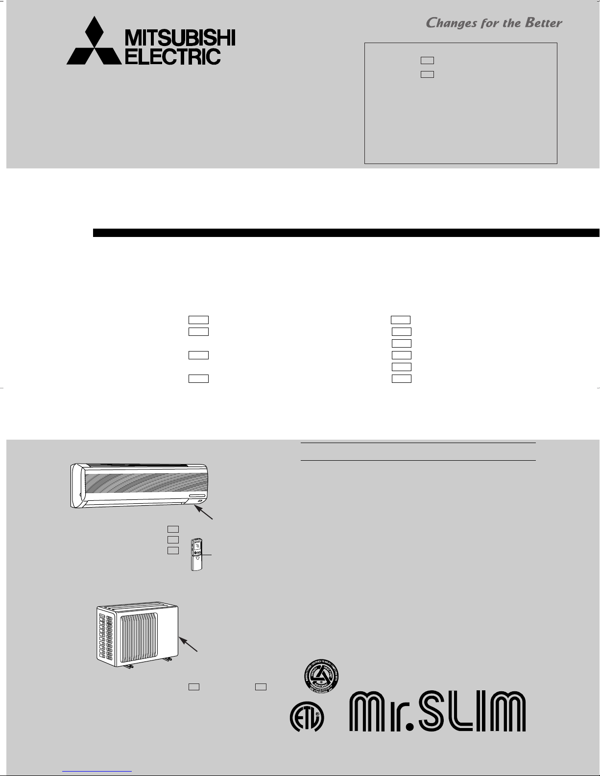
SPLIT-TYPE, HEAT PUMP AIR CONDITIONERS
L
I
S
T
E
D
CUS
SERVICE MANUAL
Wireless type
Models
MSH09TW · MUH09TW
MSH12TN · MUH12TN
MSH15TN · MUH15TN
MSH17TN · MUH17TN
MSH09TW
MSH12TN
MSH15TN
MSH17TN
-
-
-
-
· MUH09TW
· MUH12TN
· MUH12TN
· MUH15TN
· MUH15TN
· MUH17TN
Revision:
● MUH12TN- has been added.
● MUH15TN- has been added.
●REFRIGERANT SYSTEM DIAGRAM of
MXZ30TN and MXZ30TN2 has partly been
changed.
●PARTS LIST of MXZ30TN and MXZ30TN2
has partly been changed
●Please void OB275 Revised edition-C.
U2
U2
No. OB275
REVISED EDITION-D
U1U1
-
U1U1
-
U2
-
U1U1
-
U2
-
U1U1
-
Inverter-controlled multi system Model
Indication of
MSH12TN
MSH15TN
MSH17TN
INDOOR UNIT
MUH15TN
OUTDOOR UNIT
MSH12TN -
MSH15TN -
MSH17TN -
MUH15TN - MUH15TN -
U1
U1
U1
model name
Remote
controller
Indication of
model name
U2U1
· MXZ30TN
· MXZ30TN2
CONTENTS
1. FEATURES·························································2
2. TECHNICAL CHANGES····································5
3. PART NAMES AND FUNCTIONS······················7
4. INDOOR UNIT COMBINATION························10
5. SPECIFICATION···············································11
6. DATA·································································17
7. OUTLINES AND DIMENSIONS·······················39
8. WIRING DIAGRAM ··········································43
9. REFRIGERANT SYSTEM DIAGRAM··············51
10. MICROPROCESSOR CONTROL ····················54
11. SERVICE FUNCTIONS·····································72
12. TROUBLESHOOTING ······································75
13. DISASSEMBLY INSTRUCTIONS···················101
14. PARTS LIST····················································114
15. OPTIONAL PARTS·········································126
The Slim Line.
From Mitsubishi Electric.
TM
Page 2

1
MSH12TN MSH15TN MSH17TN -
U1
U1
U1
MSH12TN
MSH15TN
MSH17TN
MSH09TW
MSH09TW -
U1
MUH09TW
MUH09TW -
U1
MUH15TN -
U1
MUH15TN -
U2
U1
MUH15TN
MUH17TN -
U1
MUH17TN
MXZ30TN MXZ30TN2
LCD wireless
remote controller
MUH12TN
MUH12TN-
U2
MUH12TN-
USA Remark
MSH09TW
MSH12TN
MSH15TN
MSH17TN
No
40min.
27˚F
38˚F
CANADA
RT63(Outdoor):
for protection in low ambient temperature
Refer to
U1
U1
U1
U1
DIFFERENT POINTS between models for USA and CANADA
AMBIENT
TEMPERATURE
THERMISTOR
INTERVAL
TIME
START
TEMPERATURE
FINISH
TEMPERATURE
DEFROSTING
Have
15min.
32˚F
50˚F
8. WIRING DIAGRAM
10. MICRO PROCESSOR CONTROL
10-1. -HEAT mode of "I FEEL CONTROL"-
5. Outdoor temperature control(P. 60)
10. MICRO PROCESSOR CONTROL
10-1. -HEAT mode of "I FEEL CONTROL"-
3. Defrosting (P.59)
11. SERVICE FUNCTIONS
11-2. CHANGE IN DEFROST SETTING(P.72)
for protection in low ambient temperature
MSH09TW MSH12TN MSH15TN MSH17TN -
Model
FEATURES
2
Page 3
SWING
Model Cooling capacity Heating capacity SEER HSPF(44/55)
MSH09TW MSH09TW - 8,800Btu/h 10,500Btu/h 10.0 6.8/5.9
MSH12TN MSH12TN - 12,600/12,900Btu/h 13,000/13,500Btu/h 10.2 6.8/5.9
MSH15TN MSH15TN - 14,300/14,600Btu/h 14,500/14,800Btu/h 10.7 6.8/5.9
MSH17TN MSH17TN - 16,000/16,200Btu/h 16,800/17,200Btu/h 10.4 6.8/5.9
U1
U1
U1
U1
“I FEEL CONTROL” IN OUR LCD WIRELESS REMOTE CONTROLLER WITH ON/OFF PROGRAM TIMER
Mitsubishi Electric’s new wireless remote controller incorporates a number of advanced features that provide even greater con-
trol and ease-to-use. It has a liquid crystal display which indicates such information as mode, fan speed and temperature
selected as well as the programmed ON/OFF timer. It is also equipped with “I Feel Control”, a unique Mitsubishi Electric feature that allows the user to adjust the temperature to exactly the level he or she wants simply by tapping the button that
describes present conditions : “Too Cool” or “Too Warm”. The optimum temperature set this way is then memorized for immediate recall whenever the air conditioner is used again.
Select desired air flow direction.
REMOTE-CONTROL OPERATION MODE
Using the remote controller, you can select from five airflow settings to match room layout and the location of people. Also, you
can set the vane to swing automatically.
AUTO-RESTART FUNCTION
The auto-restart function restarts the equipment when power is
restored following an outage automatically. Operation resumes in
the mode in which the equipment was running immediately before
the outage.
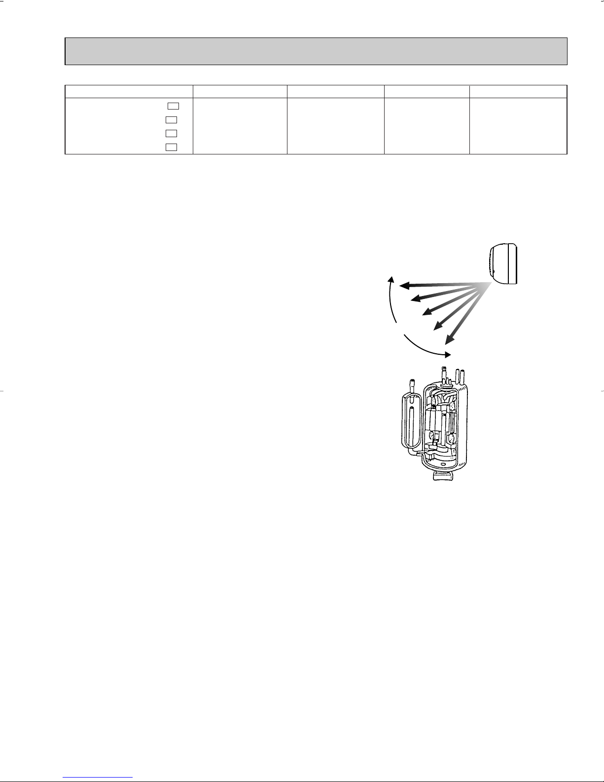
HIGH PERFORMANCE ROTARY COMPRESSOR
The advanced design of Mitsubishi Electric’s powerful and energy
efficient rotary compressor results in lower operating costs and
longer service life.
3
Page 4
Time
Set Temperature
Conventional
model
Inverter model
MXZ30TN MXZ30TN2
Time
Set Temperature
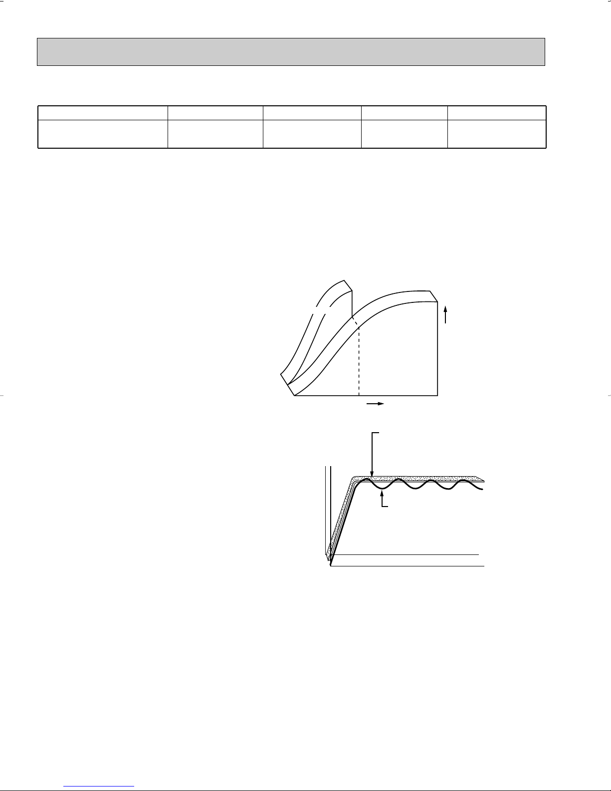
Conventional Model:
Temperature are
adjusted by switching the
compressor off and on.
Inverter Model:
Uniform temperatures are
maintained by finely tuned
control of compressor speed.
Optimum Comfort in Any Situation
Model Cooling capacity Heating capacity SEER HSPF(44)
MXZ30TN MXZ30TN2
28,400Btu/h
(4,160 - 30,500)
28,600Btu/h
(5,790 - 38,000)
11.0 7.5
Inverter Technology
Outdoor unit uses inverter compressor technology (Variable Frequency Drive) to provide exceptional indoor high-speed
cooling and heating.
By responding to indoor temperature changes, the system reduces power consumption by varying the compressor speed for
extra energy savings and performs only to the levels needed to maintain a constant and comfortable indoor environment.
Extra Energy Savings
For optimum performance inverter technology controls the electrical current to the compressor, delivering only the energy
needed to match the cooling and heat load of a room. This feature reduces energy consumption.
High-Speed Heating and Cooling
Compressor rotation is controlled to maximize
efficiency, changing speeds according to the cooling
and heating load of a room. This application means
the desired temperature is reached much faster.
Optimum Comfort Year-Round
Unlike conventional units that start and stop repetitively,
inverter units are able to detect subtle changes in room
temperature and adjust airflow automatically. This adaptation
means less temperature variation and more comfortable rooms.
4
Page 5

2
TECHNICAL CHANGES
MSH09NW2 ➔ MSH09TW
1. Indoor unit has changed.
2. Remote controller has changed.
MSH12NN2 ➔ MSH12TN
1. Remote controller has changed.
2. Union size of connect pipe for gas has changed.
MSH15NN2 ➔ MSH15TN
MSH17NN2 ➔ MSH17TN
1. Remote controller has changed.
MUH09NW2 ➔ MUH09TW
1. Outdoor unit has changed.
MUH12NN2 ➔ MUH12TN
1. Outdoor unit has changed.
MUH15NN2 ➔ MUH15TN
1. Only model name has changed.
MUH17NN2 ➔ MUH17TN
1. Valve type has changed (Size for connecting pipe is the same).
MSH09NW2 - ➔ MSH09TW -
1. Indoor unit has changed.
2. Remote controller has changed.
MSH12NN2 - ➔ MSH12TN -
1. Remote controller has changed.
2. Union size of connect pipe for gas has changed.
MSH15NN2 - ➔ MSH15TN MSH17NN2 - ➔ MSH17TN -
1. Remote controller has changed.
MUH09NW2 - ➔ MUH09TW -
1. Outdoor unit has changed.
MUH12NN2 - ➔ MUH12TN -
1. Outdoor unit has changed.
MUH15NN2 - ➔ MUH15TN -
1. Only model name has changed.
U1U1
U1U1
U1U1
U1U1
U1U1
U1U1
U1U1
MUH17NN2 - ➔ MUH17TN -
1. Valve type has changed (Size for connecting pipe is the same).
MXZ30TN
1. New model.
U1U1
5
Page 6

MXZ30TN ➔ MXZ30TN2
1. Noise filter P.C. board has changed to improve the capacity for protecting the inverter-controlled circuit when the
voltage higher than the rated one is aupplied with the inverter-controlled circuit.
2. Noise filter P.C. board for “MXZ30TN” and “MXZ30TN2” are not interchangeable.
3. Service parts have been changed as follows according to above change;
•The value of R(resistor)has changed. 10Ω ➔ 20Ω
•TB5(terminal block) has been removed.
MUH12TN - ➔ MUH12TN MUH15TN - ➔ MUH15TN -
U2U1
U2U1
1. Outdoor haet exchanger has changed.
Outdoor haet exchanger for “TN - ” and “TN - ” are not interchangeable.
U2U1
6
Page 7
3
Installation plate
Installation plate fixing screw 4 x 25 mm(0.16 x 0.98 in.)
Remote controller mounting hardware
Fixing screw for 3 3.5 x 16 mm(0.14 x 0.63 in.) (Black)
Battery (AAA) for remote controller
Wireless remote controller
Felt tape (Used for left or left-rear piping)
1
5
1
2
2
1
1
1
2
3
4
5
6
7
MSH12TN
MSH15TN
MSH17TN
MSH09TW MSH09TW -
U1
1
6
1
2
2
1
1
MSH12TN
-
MSH15TN
-
MSH17TN
-
U1
U1
U1
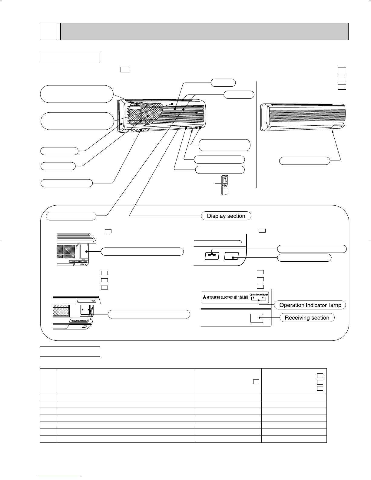
PART NAMES AND FUNCTIONS
INDOOR UNIT
MSH09TW MSH09TW -
Deodorizing filter(option)
(gray sponge type)
Air cleaning filter(option)
(white bellows type)
Front panel
Air filter
Vertical vanes
Operation section
(When the grille is opened)
MSH09TW MSH09TW -
U1
U1
Grille
MSH12TN
MSH15TN
MSH17TN
MSH12TN MSH15TN MSH17TN -
U1
U1
U1
Air inlet
Remote control
receiving section
Model indication
Model indication
Horizontal vane
Remote controller
MSH09TW MSH09TW -
U1
Emergency operation switch
MSH12TN MSH12TN MSH15TN MSH15TN MSH17TN MSH17TN -
U1
U1
U1
Emergency operation switch
ACCESSORIES
MSH12TN MSH12TN MSH15TN MSH15TN MSH17TN MSH17TN -
7
U1
U1
U1
Operation indicator lamp
Receiving section
Page 8
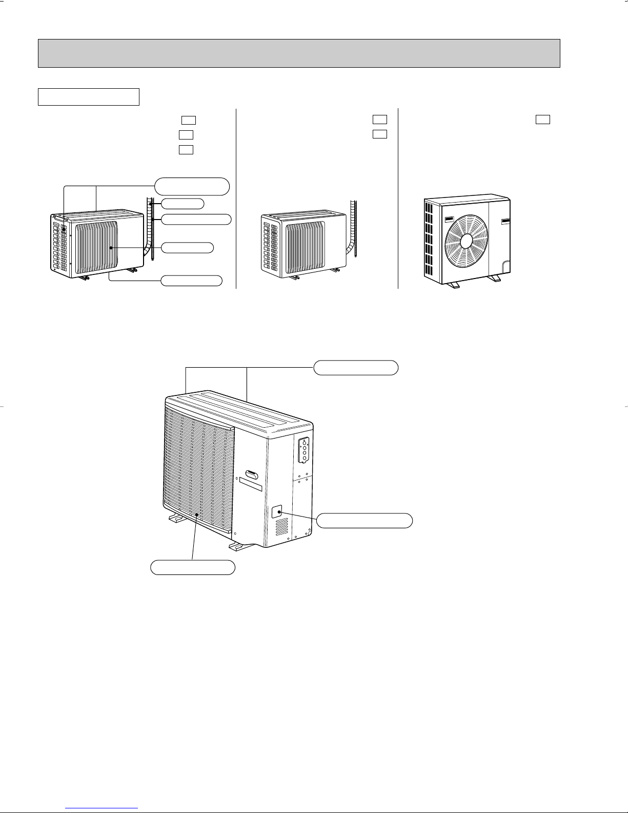
Air inlet
Piping
Drain hose
Air outlet
Drain outlet
(back and side)
OUTDOOR UNIT
Air inlet
Air outlet
(back and side)
Model indication
MUH09TW MUH09TW MUH12TN MUH12TN -
MUH12TN -
MXZ30TN MXZ30TN2
U1
U1
U2
MUH15TN
MUH15TN MUH15TN -
U1
MUH17TN MUH17TN -
U2
U1
8
Page 9
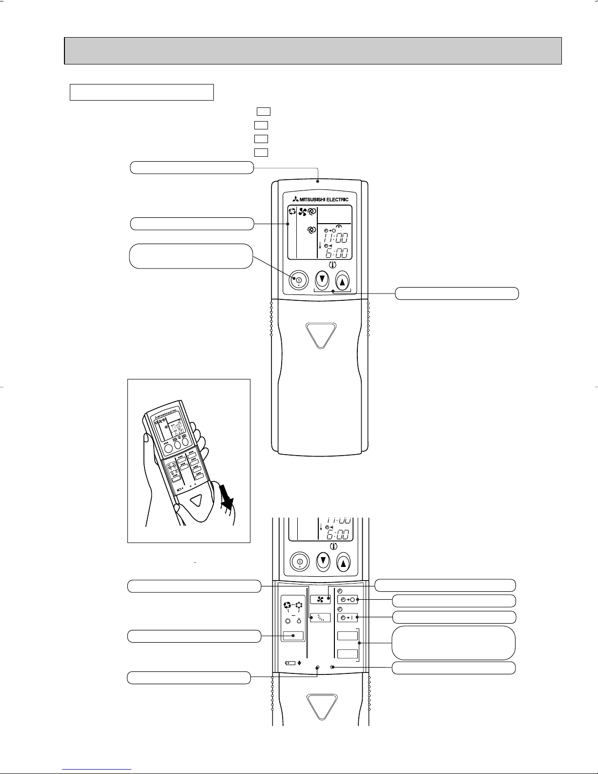
REMOTE CONTROLLER
ON/OFF
TOO
COOL
PM
AM
TOO
WARM
ON/OFF
FAN
TOO
WARM
TOO
COOL
VANE
MODE
STOP
START
HR.
MIN.
I FEEL
COOL
HEAT
DRY
PM
CLOCK
AM
RESET CLOCK
Open the front lid.
Signal transmitting section
Operation display section
OPERATE /STOP
(ON /OFF)button
TEMPERATURE buttons
OPERATION SELECT button
FAN SPEED CONTROL button
OFF-TIMER button
HR. button
MIN. button
(TIME SET button)
ON-TIMER button
RESET button
VANE CONTROL button
CLOCK SET button
MSH09TW
MSH12TN
MSH15TN
MSH17TN
MSH09TW MSH12TN MSH15TN MSH17TN -
U1
U1
U1
U1
9
Page 10
4
09
12
15
17
09+09
09+12
09+15
09+17
12+12
09+09+09
09+09+12
90
90
90
90
90
90
90
90
90
90
90
4.0
4.9
4.9
8.6
8.6
8.9
8.9
10.5
10.6
13.6
14.9
4.5
5.4
5.4
9.5
9.5
9.9
9.9
11.6
11.7
15.1
16.4
–
–
–
–
–
–
–
–
–
8,800
13,660
8,800
(4,160~9,210)
12,900
(5,600~15,350)
14,600
(5,600~17,010)
16,200
(6,470~18,720)
17,600
(5,470~18,680)
21,700
(6,240~22,760)
23,400
(6,240~24,030)
25,000
(6,220~27,170)
25,800
(6,300~27,900)
26,400
(9,740~29,150)
28,400
(9,940~30,500)
1,030
(510~1,280)
1,250
(510~1,680)
1,250
(510~1,780)
2,200
(500~2,620)
2,200
(550~3,230)
2,280
(540~3,270)
2,280
(540~3,430)
2,680
(550~4,000)
2,700
(540~4,100)
3,500
(700~4,500)
3,800
(810~4,610)
–
–
–
–
8,800
12,900
14,600
16,200
12,900
8,800
7,370
8,800
12,900
14,600
16,200
8,800
8,800
8,800
8,800
12,900
8,800
7,370
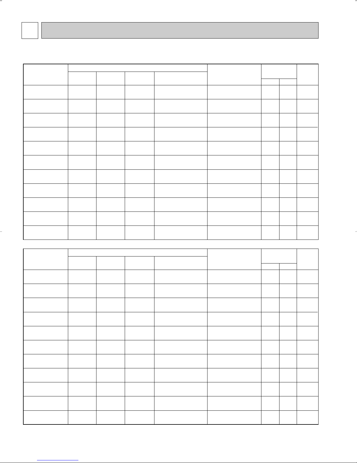
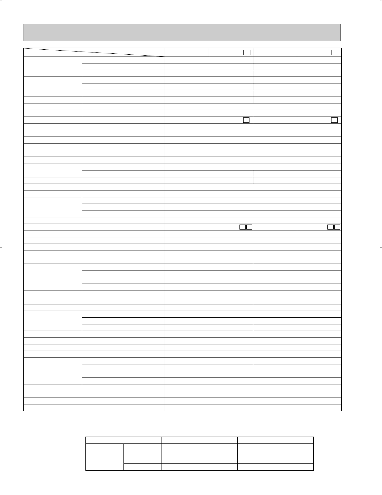
Indoor units
combination
Unit A Unit B Unit C
Cooling capacity (BTU/h)
Total
Outdoor unit
power consumption
(W)
Current
(A)
Power
factor
(%)
208V 230V
NOTE: Electrical data is for outdoor unit only.
MXZ30TN MXZ30TN2
09
12
15
17
09+09
09+12
09+15
09+17
12+12
09+09+09
09+09+12
90
90
90
90
90
90
90
90
90
90
90
4.3
4.7
5.5
6.3
7.6
8.6
9.4
10.6
9.9
10.6
11.0
4.8
5.2
6.1
6.9
8.4
9.6
10.4
11.7
10.9
11.8
12.1
–
–
–
–
–
–
–
–
–
9,530
12,960
10,500
(5,790~16,950)
13,500
(6,420~22,400)
14,800
(6,470~23,180)
17,200
(6,520~23,550)
21,000
(6,520~26,900)
24,000
(6,730~30,000)
25,300
(7,490~32,240)
27,700
(8,140~37,100)
27,000
(7,660~36,890)
28,590
(8,900~37,500)
28,600
(9,040~38,000)
1,100
(560~1,990)
1,200
(560~2,340)
1,400
(570~2,480)
1,600
(600~2,710)
1,950
(620~2,900)
2,210
(640~3,130)
2,400
(640~3,360)
2,700
(690~3,900)
2,520
(650~3,850)
2,720
(710~3,920)
2,800
(710~3,970)
–
–
–
–
10,500
13,500
14,800
17,200
13,500
9,530
7,820
10,500
13,500
14,800
17,200
10,500
10,500
10,500
10,500
13,500
9,530
7,820
Indoor units
combination
Unit A Unit B Unit C
Heating capacity (BTU/h)
Total
Outdoor unit
power consumption
(W)
Current
(A)
Power
factor
(%)
208V 230V
INDOOR UNITS COMBINATION
10
Page 11
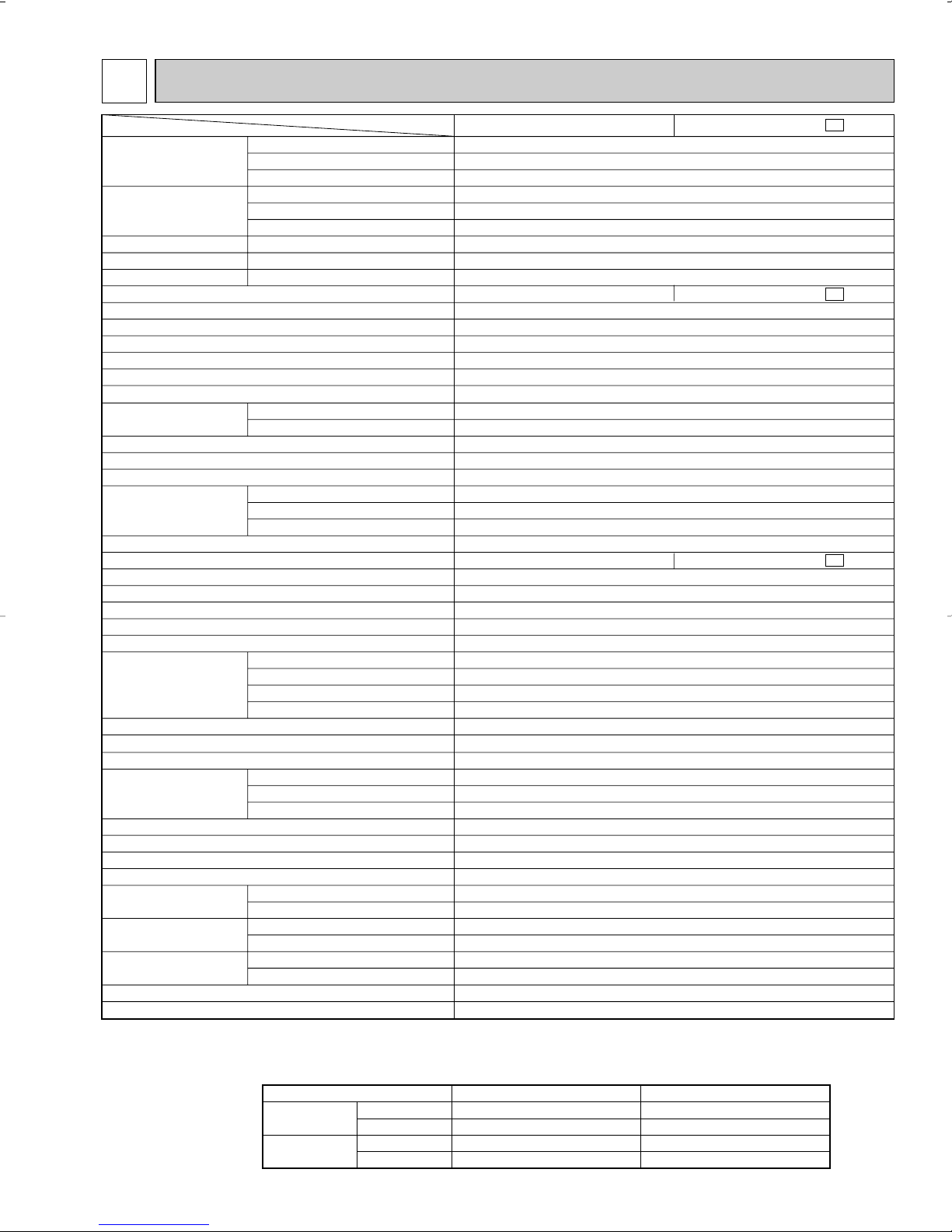
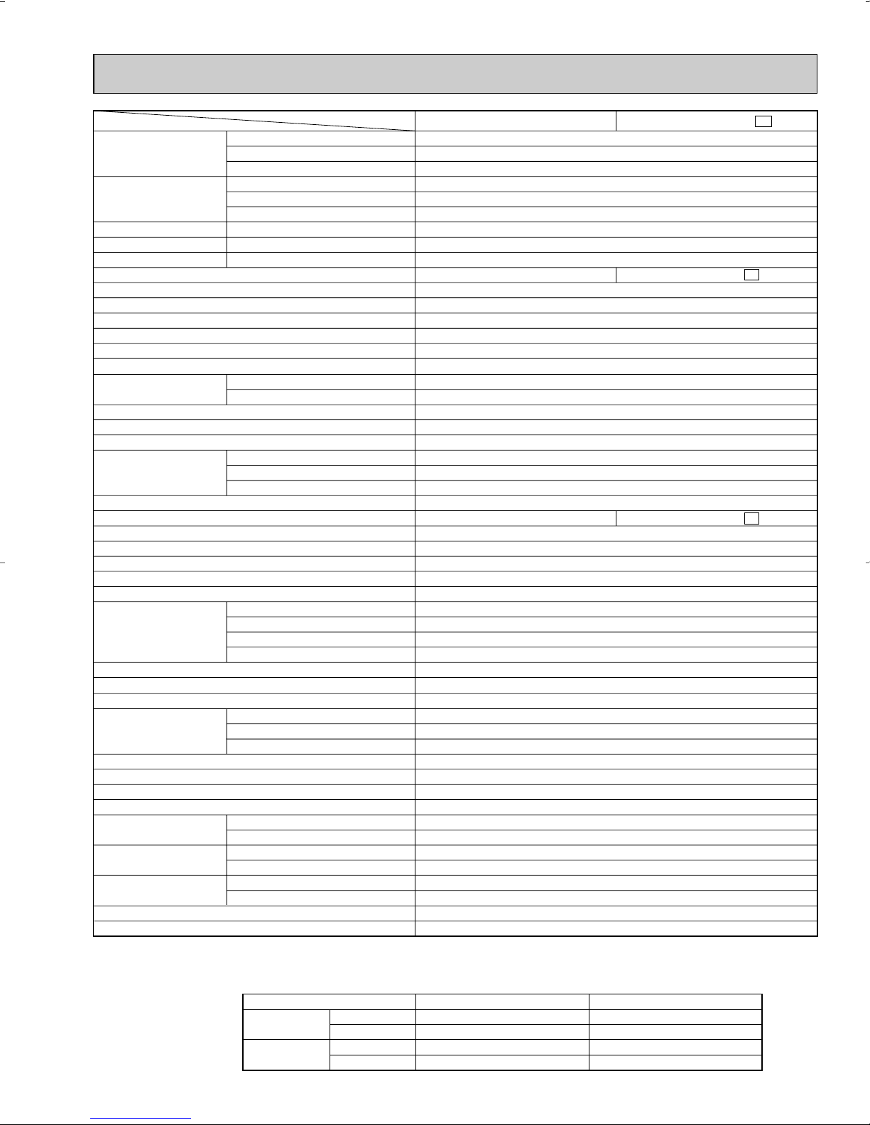
5
Item
Model
MSH09TW -
Capacity
Power
consumption
EER [SEER]
HSPF IV(V)
COP
INDOOR UNIT MODEL
External finish
Power supply
Max. fuse size (time delay)/ Disconnect switch
Min. circuit ampacity
Fan motor
Auxiliary heater
Airflow Low—Med.—High
Moisture removal
Sound level Low-Med.-High
Cond. drain connection O.D.
Dimensions
Weight
OUTDOOR UNIT MODEL
External finish
Power supply
Max. fuse size (time delay)
Min. circuit ampacity
Fan motor
Compressor
Refrigerant control
Sound level
Defrost method
Dimensions
Weight
REMOTE CONTROLLER
Control voltage (by built-in transformer)
REFRIGERANT PIPING
Pipe size
(Min. wall thickness)
Connection method
Between the indoor
& outdoor units
Refrigerant charge (R22)
Refrigerating oil (Model)
Btu/h
Btu/h
Btu/h
W
W
V, phase, Hz
A
A
F.L.A
A(kW)
CFM
CFM
pt./h
dB(A)
in.
in.
in.
in.
Ib.
V, phase, Hz
A
A
F.L.A
R.L.A
L.R.A
dB(A)
in.
in.
in.
Ib.
in.
in.
ft.
ft.
lb.
oz.
8,800
10,500
5,300
890
890
820
9.9 [10.0]
6.8 (5.9)
3.46
White
115, 1, 60
15
0.5
0.37
–
198-244-297
173(145)-226(187)-279(233)
2.3
26-31-36
5/8
33-1/2
7-1/2
10-15/16
20
Munsell 5Y 7/1
115, 1, 60
20
16
0.60
RH140WGJT
C-R 0.83 C-S 1.48
12.0
42.0
Capillary tube
47
Reverse cycle
30-23/32
10-1/32
21-1/4
82
Wireless type
12V DC
Not supplied (optional parts)
1/4 (0.0265)
3/8 (0.0285)
Flared
Flared
Max. 25
Max. 49
2 Ib. 3 oz.
9.3 (MS56)
❈1 ❈3
❈1
❈1
❈2
❈1
❈1
❈2
Cooling
Heating 47
Heating 17
Cooling
Heating 47
Heating 17
Cooling
Heating
Heating
MSH09TW
MSH09TW - MSH09TW
U1
U1
MUH09TW - MUH09TW
U1
HEAT Dry
COOL Dry(Wet)
W
D
H
Model
Winding resistance (at 68˚F) Ω
W
D
H
Liquid
Gas
Indoor
Outdoor
Height difference
Piping length
❈1
Cooling
Heating
Maximum
Minimum
Maximum
Minimum
Indoor intake air temperature
95˚FDB, 71˚FWB
67˚FDB, 57˚FWB
80˚FDB, 67˚FWB
70˚FDB, 60˚FWB
Outdoor intake air temperature
115˚FDB
67˚FDB
75˚FDB, 65˚FWB
17˚FDB, 15˚FWB
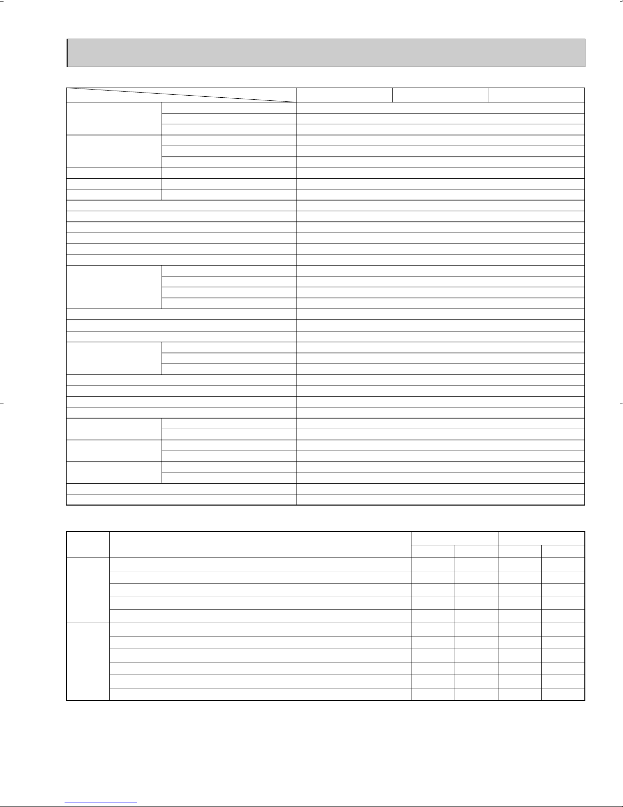
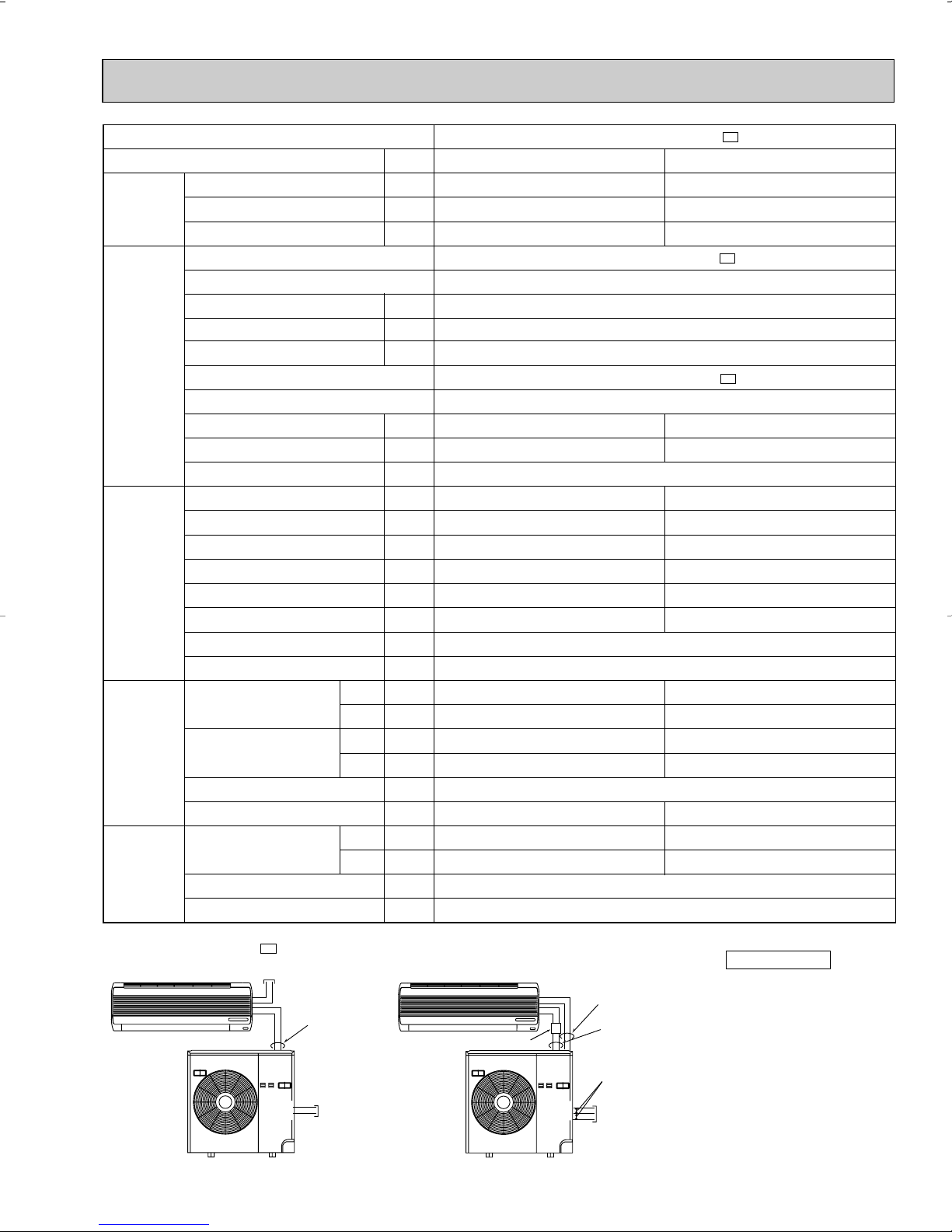
SPECIFICATIONS
NOTE : Test conditions are based on ARI 210/240.
❈1 : Rating conditions(cooling) — Indoor : 80˚FDB, 67˚FWB, Outdoor : 95˚FDB, (75˚FWB)
❈2 : (heating) — Indoor : 70˚FDB, 60˚FWB, Outdoor : 17˚FDB, 15˚FWB
❈3 : (cooling) — Indoor : 80˚FDB, 67˚FWB, Outdoor : 82˚FDB, 65˚FWB
Operating Range
(heating) — Indoor : 70˚FDB, 60˚FWB, Outdoor : 47˚FDB, 43˚FWB
11
Page 12
Item
Model
MSH12TN
MSH15TN
Capacity
Power
consumption
EER [SEER]
HSPF IV (V)
COP
INDOOR UNIT MODEL
External finish
Power supply
Max. fuse size (time delay)/ Disconnect switch
Min. circuit ampacity
Fan motor
Auxiliary heater
Airflow Low—Med.—High
Moisture removal
Sound level Low-Med.-High
Cond. drain connection O.D.
Dimensions
Weight
OUTDOOR UNIT MODEL
External finish
Power supply
Max. fuse size (time delay)
Min. circuit ampacity
Fan motor
Compressor
Refrigerant control
Sound level
Defrost method
Dimensions
Weight
REMOTE CONTROLLER
Control voltage (by built-in transformer)
REFRIGERANT PIPING
Pipe size
(Min. wall thickness)
Connection method
Between the indoor
& outdoor units
Refrigerant charge (R22)
Refrigerating oil (Model)
Btu/h
Btu/h
Btu/h
W
W
V, phase, Hz
A
A
F.L.A
A(kW)
CFM
CFM
pt./h
dB(A)
in.
in.
in.
in.
Ib.
V, phase, Hz
A
A
F.L.A
R.L.A
L.R.A
dB(A)
in.
in.
in.
Ib.
in.
in.
ft.
ft.
lb.
oz.
12,600/12,900
13,000/13,500
6,800/7,000
1,280/1,310
1,180/1,250
1,110/1,140
9.8/9.8[10.2/10.2]
3.23/3.17
311-339-388
3.3
15
0.42
RH189NHDT
49
30-23/32
10-1/32
21-1/4
86
1/2 (0.0285)
2 Ib. 12 oz.
6.8/6.8 (5.9/5.9)
White
115, 1, 60
15
0.6
0.43
–
360-395-452
36-39-42
5/8
39-15/16
7-1/2
12-5/8
31
Munsell 5Y7/1
208/230, 1, 60
14
C-R 1.68 C-S 2.78
10.0
35.0
Capillary tube
Reverse cycle
Wireless type
12V DC
Not supplied (optional parts)
1/4 (0.0265)
Flared
Flared
Max. 25
Max. 50
16.1 (MS56)
14,300/14,600
14,500/14,800
8,700/8,900
1,350/1,380
1,250/1,300
1,210/1,240
10.6/10.6 [10.7/10.7]
3.40/3.34
293-321-367
4.7
20
0.52
RH207NHDT
53
33-7/16
11-7/16
23-13/16
99
5/8 (0.0315)
3 lb. 3 oz.
❈1 ❈3
❈1
❈1
❈2
❈1
❈1
❈2
Cooling
Heating 47
Heating 17
Cooling
Heating 47
Heating 17
Cooling
Heating
Heating
(208/230V)
(208/230V)
(208/230V)
(208/230V)
(208/230V)
(208/230V)
(208/230V)
(208/230V)
(208/230V)
MSH12TN -
MSH15TN -
MSH12TN
MSH12TN -
U1
MSH15TN
MSH15TN -
U1
U1
MUH12TN
MUH12TN -
U1 U2
MUH15TN
MUH15TN -
U1 U2
U1
Dry
Wet
W
D
H
Model
Winding resistance (at 68˚F) Ω
W
D
H
Liquid
Gas
Indoor
Outdoor
Height difference
Piping length
Cooling
Heating
Maximum
Minimum
Maximum
Minimum
Indoor intake air temperature
95˚FDB, 71˚FWB
67˚FDB, 57˚FWB
80˚FDB, 67˚FWB
70˚FDB, 60˚FWB
Outdoor intake air temperature
115˚FDB
67˚FDB
75˚FDB, 65˚FWB
17˚FDB, 15˚FWB
NOTE : Test conditions are based on ARI 210/240.
❈1 : Rating conditions(cooling) — Indoor : 80˚FDB, 67˚FWB, Outdoor : 95˚FDB, (75˚FWB)
❈2 : (heating) — Indoor : 70˚FDB, 60˚FWB, Outdoor : 17˚FDB, 15˚FWB
❈3 : (cooling) — Indoor : 80˚FDB, 67˚FWB, Outdoor : 82˚FDB, 65˚FWB
Operating Range
(heating) — Indoor : 70˚FDB, 60˚FWB, Outdoor : 47˚FDB, 43˚FWB
12
Page 13
Item Model
❈1
Capacity
Power
consumption
❈1 ❈3
EER [SEER]
HSPF IV (V)
COP
Cooling
Heating 47
Heating 17
Cooling
❈1
Heating 47
Heating 17
Cooling
Heating
Heating
(208/230V)
❈1
(208/230V)
❈2
(208/230V)
(208/230V)
❈1
(208/230V)
❈2
(208/230V)
(208/230V)
(208/230V)
(208/230V)
Btu/h
Btu/h
Btu/h
INDOOR UNIT MODEL
W
W
MSH17TN
MSH17TN MSH17TN External finish
Power supply
Max. fuse size (time delay)/ Disconnect switch
Min. circuit ampacity
Fan motor
Auxiliary heater
Airflow Low—Med.—High
Dry
Wet
Moisture removal
Sound level Low-Med.-High
Cond. drain connection O.D.
W
Dimensions
D
H
Weight
OUTDOOR UNIT MODEL
V, phase, Hz
A
A
F.L.A
A(kW)
CFM
CFM
pt./h
dB(A)
in.
in.
in.
in.
lb.
MUH17TN MUH17TN External finish
Power supply
Max. fuse size (time delay)
Min. circuit ampacity
Fan motor
V, phase, Hz
A
A
F.L.A
Model
Compressor
Winding resistance (at 68˚F) Ω
R.L.A
L.R.A
Refrigerant control
Sound level
dB(A)
Defrost method
in.
in.
in.
lb.
Dimensions
Weight
W
D
H
REMOTE CONTROLLER
Control voltage (by built-in transformer)
REFRIGERANT PIPING
Pipe size
(Min. wall thickness)
Connection method
Between the indoor
& outdoor units
Liquid
Gas
Indoor
Outdoor
Height difference
Piping length
Refrigerant charge (R22)
Refrigerating oil (Model)
NOTE : Test conditions are based on ARI 210/240.
❈1 : Rating conditions (cooling) — Indoor : 80˚FDB, 67˚FWB, Outdoor : 95˚FDB, (75˚FWB)
❈2 : (heating) — Indoor : 70˚FDB, 60˚FWB, Outdoor : 17˚FDB, 15˚FWB
❈3 : (cooling) — Indoor : 80˚FDB, 67˚FWB, Outdoor : 82˚FDB, 65˚FWB
(heating) — Indoor : 70˚FDB, 60˚FWB, Outdoor : 47˚FDB, 43˚FWB
Operating Range
Cooling
Heating
Maximum
Minimum
Maximum
Minimum
in.
in.
ft.
ft.
lb.
oz.
Indoor intake air temperature
95˚FDB, 71˚FWB
67˚FDB, 57˚FWB
80˚FDB, 67˚FWB
70˚FDB, 60˚FWB
13
MSH17TN -
16,000/16,200
16,800/17,200
10,100/10,300
1,560/1,580
1,500/1,570
1,410/1,510
10.3/10.3 (10.4/10.4)
6.8/6.8 (5.9/5.9)
3.28/3.21
White
115, 1, 60
15
0.7
0.51
–
406-441-491
342-371-413
5.1
40-43-45
5/8
39-15/16
7-1/2
12-5/8
31
Munsell 5Y 7/1
208/230, 1, 60
20
15
0.75
RH231NHDT
C-R 1.65 C-S2.67
11.0
38.0
Capillary tube
53
Reverse cycle
34-1/4
11-5/8
33-1/2
128
Wireless type
12V DC
Not supplied (optional parts)
1/4 (0.0265)
5/8 (0.0315)
Flared
Flared
Max. 25
Max. 50
4lb. 14oz.
16.1 (MS56)
Outdoor intake air temperature
115˚FDB
67˚FDB
75˚FDB, 65˚FWB
17˚FDB, 15˚FWB
U1
U1
U1
Page 14
Indoor
unit
w Max. Height
difference 25ft.
Outdoor unit
Refrigerant Piping
Max.length
A
w Height difference should be within
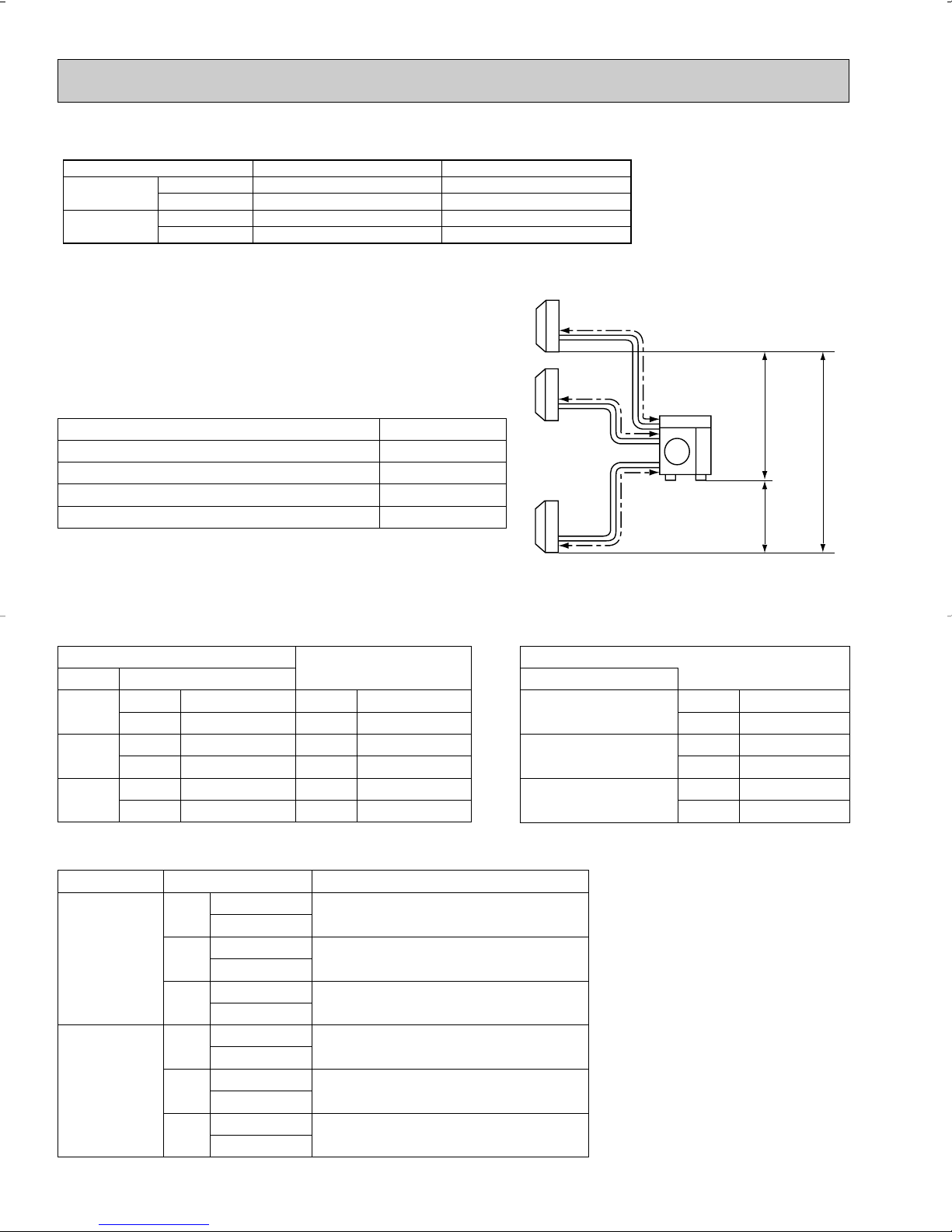
25ft. regardless of which unit,
indoor or outdoor position is high.
Outside
diameter
Minimum
Wall
thickness
Outside
diameter
Minimum
Wall
thickness
MSH09TW
MUH09TW
MSH12TN
MUH12TN
MSH15TN
MUH15TN
MSH17TN
MUH17TN
MSH09TWMUH09TW-
MSH12TNMUH12TNMUH12TN-
MSH15TNMUH15TNMUH15TN-
MSH17TNMUH17TN-
Additional piping
Max. length : ft.
A
50
Gas
Piping size : in. Length of connecting pipe : in.
Liquid
Indoor unit
Outdoor unit
Model
U1
U1
U1
U1
U2
U1
U1
U2
U1
U1
Gas :
Liquid :00
Gas :
Liquid :
16-15/16
19-11/16
[ 3/8
[ 1/2
[ 5/8
[ 1/4
0.0285
0.0315
0.0265
MAX. REFRIGERANT PIPING LENGTH
MAX. HEIGHT DIFFERENCE
14
Page 15
Item Model
Cooling
Heating
Mode
❈1: "A" Cooling Steady State at rated compressor Speed
❈3: "B-2" Cooling Steady State at rated compressor Speed
"B-1" Cooling Steady State at minimum compressor Speed
Low ambient Cooling Steady State at minimum compressor Speed
Intermediate Cooling Steady State At Intermediate compressor Speed
w
❈1: Standard Rating-Heating at rated compressor Speed
❈2: Low temperature Heating at rated compressor Speed
Max temperature Heating at minimum compressor Speed
High temperature Heating at minimum compressor Speed
Frost Accumulation at rated compressor Speed
Frost Accumulation at Intermediate compressor Speed
w
Test
Indoor air condition Outdoor air condition
Dry bulb
Wet bulb
Dry bulb
Wet bulb
80
80
80
80
80
70
70
70
70
70
70
67
67
67
67
67
60
60
60
60
60
60
95
82
82
67
87
47
17
62
47
35
35
(75)
(65)
(65)
(53.5)
(69)
43
15
56.5
43
33
33
w
At Intermediate compressor Speed
=("Cooling rated compressor speed" - "minimum compressor speed") / 3 + "minimum compressor speed".
Unit: ˚F
Capacity
Power
consumption
❈1 ❈3
EER [SEER]
HSPF IV (V)
COP
Cooling
❈1
Heating 47
Heating 17
Cooling
❈1
Heating 47
Heating 17
Cooling
Heating
Heating
❈1
❈2
❈1
❈2
Btu/h
Btu/h
Btu/h
OUTDOOR UNIT MODEL
External finish
Power supply
V, phase, Hz
Max. fuse size (time delay)
Min. circuit ampacity
Fan motor
F.L.A
Model
Compressor
Winding resistance (at 68˚F) Ω
R.L.A
L.R.A
Refrigerant control
Sound level
dB(A)
Defrost method
W
Dimensions
D
H
Weight
REMOTE CONTROLLER
Control voltage (by built-in transformer)
REFRIGERANT PIPING
Pipe size
(Min. wall thickness)
Connection method
Between the indoor
& outdoor units
Liquid
Gas
Indoor
Outdoor
Height difference
Piping length (a+b+c)
Refrigerant charge (R22)
Refrigerating oil (Model)
W
W
in.
in.
in.
lb.
in.
in.
ft.
ft.
lb.
oz.
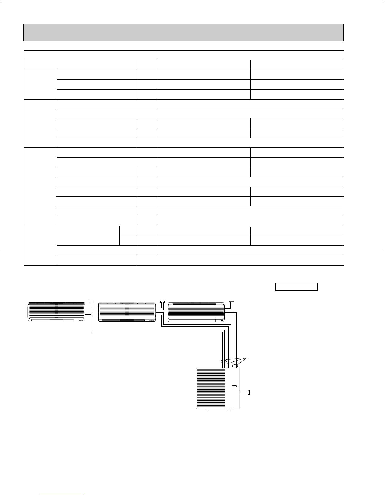
Triple-Unit Double-Unit Single-Unit
28,400/(9,940~30,500)
28,600/(9,040~38,000)
(18,100)
3,800/(810~4,610)
2,800/(710~3,970)
(2,310)
11.0
7.5
3.08
MXZ30TN MXZ30TN2
Munsell 5Y 8/1
208/230, 1, 60
A
A
30
25
1.0
THV-247FBA
U-V 0.61 V-W 0.61 W-U 0.61
15
72
LEV
47
Reverse cycle
35-7/16
12-19/32 (+1+3/8)
35-7/16
176
Wireless type
12V DC
Not supplied (optional parts)
1/4 (0.0265)
A:1/2(0.0285), B,C:3/8(0.0285)
Flared
Flared
Max. 33
Max. 200
8lb. 10oz.
26.7 (MS56)
NOTE : Test conditions are based on ARI 210/240.
15
Page 16
a
b
c
Outdoor
unit
Indoor
units
H
H
H
Liquid {1/4
Gas {3/8
Liquid {1/4
Gas {1/2
Liquid {1/4
Gas {5/8
Liquid {1/4
Gas {3/8
Liquid {1/4
Gas {1/2
Liquid {1/4
Gas {5/8
Use a different-diameter pipe of the option
MAC-455JP ({1/2 ➔ {3/8)
Use a different-diameter pipe of the option
MAC-456JP ({1/2 ➔ {5/8)
Indoor unit can be connected directly
Indoor unit can be connected directly
Use a different-diameter pipe of the option
MAC-454JP ({3/8 ➔ {1/2)
It is not possible to connect
09
12
15/17
09
12
15/17
Outdoor unit
A
Liquid {1/4
Gas {1/2
B, C
Liquid {1/4
Gas {3/8
Indoor unit Connection method
Cooling
Heating
Maximum
Minimum
Maximum
Minimum
Indoor intake air temperature
95˚FDB, 71˚FWB
67˚FDB, 57˚FWB
80˚FDB, 67˚FWB
70˚FDB, 60˚FWB
Outdoor intake air temperature
115˚FDB
67˚FDB
75˚FDB, 65˚FWB
17˚FDB, 15˚FWB
Operating Range MXZ30TN MXZ30TN2
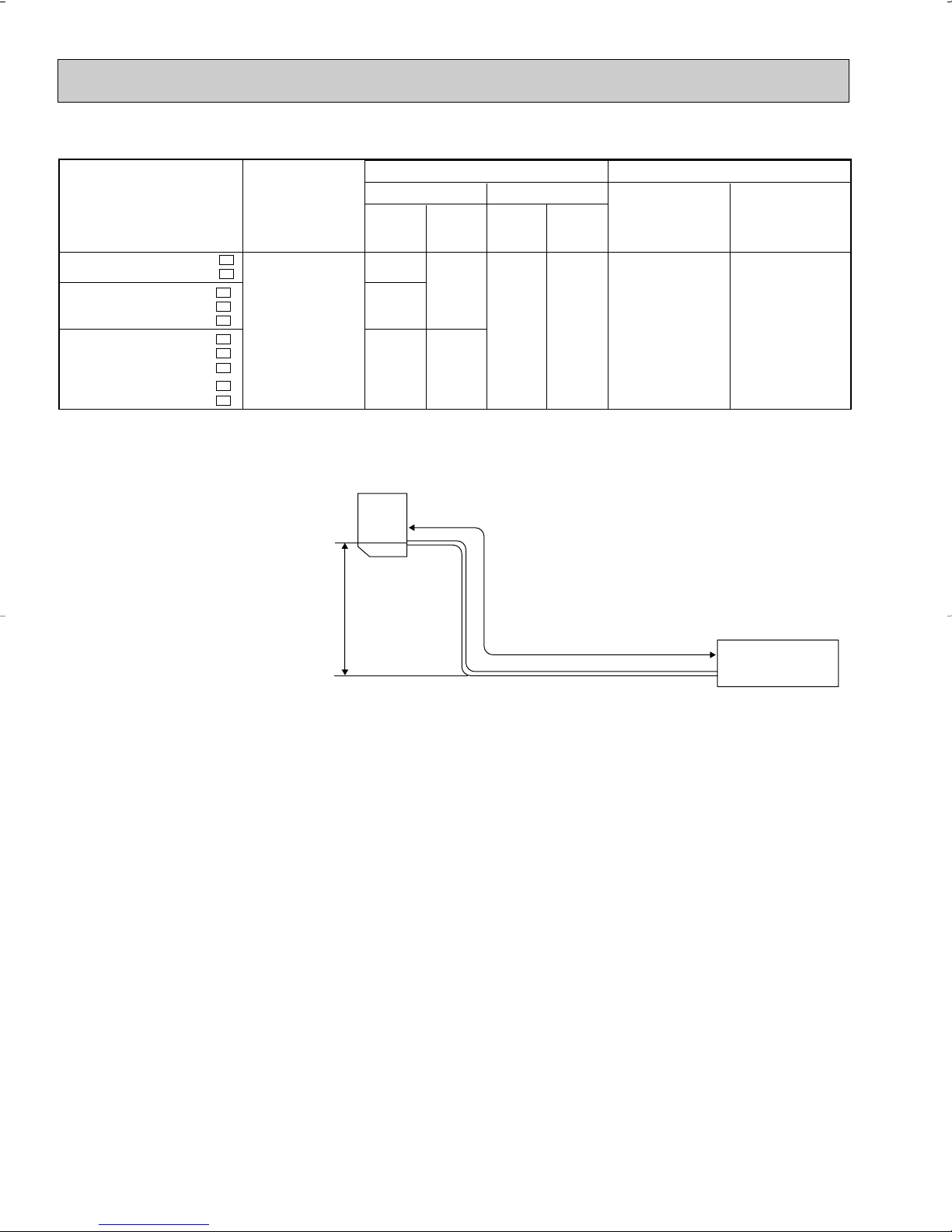
MAX. REFRIGERANT PIPING LENGTH & PIPE SIZE SELECTION
MXZ30TN MXZ30TN2
Piping length each indoor unit (a, b, c) 82ft. MAX.
Total piping length (a+b+c) 200ft. MAX.
Height difference between units (H) 33ft. MAX.
Bending point for each unit 25 MAX.
Total bending point 60 MAX.
❋It does not matter which unit is higher.
● Refrigerant pipe diameter is different according to indoor unit to be connected. When using extension pipes,refer to the
tables below.
● When diameter of refrigerant pipe is different from that of outdoor unit union, use optional Different-diameter pipe.
For further information on Different-diameter pipe,see page 128.
Indoor unit
class Pipe diameter
09
12
15/17
Liquid 1/4 Liquid 1/4
Gas 3/8 Gas 3/8
Liquid 1/4 Liquid 1/4
Gas 1/2 Gas 1/2
Liquid 1/4 Liquid 1/4
Gas 5/8 Gas 5/8
Extension pipe diameter
Outdoor unit union diameter
For
Indoor unit A
Indoor unit B
Indoor unit C
Liquid 1/4
Gas 1/2
Liquid 1/4
Gas 3/8
Liquid 1/4
Gas 3/8
Unit : inch
● Please connect the indoor unit and the outdoor unit as shown in the table below.
16
Page 17
6
Model
Indoor air Outdoor intake air DB temperature(˚F
)
71
67
63
71
67
63
71
67
63
TC
15.8
15.0
14.1
17.9
16.9
15.9
19.8
18.8
17.7
SHC
9.1
10.6
11.9
9.2
11.0
12.5
10.1
12.0
13.7
TPC
1.17
1.10
1.05
1.23
1.16
1.10
1.41
1.33
1.26
TC
14.8
13.9
13.0
16.7
15.8
14.7
18.5
17.5
16.4
SHC
8.5
9.9
11.0
8.6
10.2
11.6
9.4
11.2
12.7
TPC
1.28
1.21
1.16
1.35
1.28
1.22
1.54
1.46
1.40
TC
13.9
12.9
12.1
15.7
14.6
13.7
17.4
16.2
15.2
SHC
8.0
9.2
10.2
8.1
9.5
10.8
8.8
10.4
11.8
TPC
1.38
1.31
1.25
1.45
1.38
1.32
1.66
1.58
1.51
TC
12.9
12.0
11.0
14.6
13.6
12.5
16.2
15.1
13.9
SHC
7.4
8.5
9.3
7.5
8.8
9.8
8.2
9.6
10.7
TPC
1.45
1.39
1.34
1.52
1.46
1.41
1.75
1.67
1.61
TC
11.9
11.0
10.1
13.4
12.5
11.4
14.9
13.9
12.6
SHC
6.8
7.8
8.5
6.9
8.1
8.9
7.6
8.9
9.8
TPC
1.51
1.45
1.39
1.59
1.53
1.46
1.82
1.75
1.67
IWB
(˚F)
75 85 95 105 115
MSH12TN
MSH12TN -
MSH15TN
MSH15TN -
MSH17TN
MSH17TN -
NOTE 1. IWB : Intake air wet-bulb temperature
TC : Total Capacity (x10
3
Btu/h), SHC : Sensible Heat Capacity (x10
3
Btu/h)
TPC : Total Power Consumption (kW)
2. SHC is based on 80˚F of indoor intake air DB temperature.
U1
U1
U1
(230V)
DATA
MSH09TW
MSH12TN
MSH15TN
MSH17TN
MSH09TW MSH12TN MSH15TN MSH17TN -
6-1. PERFORMANCE DATA
1) COOLING CAPACITY
(115V)
Indoor air Outdoor intake air DB temperature(˚F
MSH09TW
MSH09TW -
(208V)
MSH12TN
MSH12TN -
MSH15TN
MSH15TN -
MSH17TN
MSH17TN -
Model
U1
Model
U1
U1
U1
IWB
(˚F)
71
67
63
Indoor air Outdoor intake air DB temperature(˚F
IWB
(˚F)
71
67
63
71
67
63
71
67
63
U1
MUH09TW
U1
MUH12TN
U1
MUH15TN
U1
MUH17TN
75 85 95 105 115
TC
SHC
TPC
10.8
6.1
0.79
10.2
7.1
0.75
9.6
8.0
0.71
75 85 95 105 115
TC
SHC
TPC
15.4
8.9
1.14
14.6
10.4
1.08
13.7
11.6
1.02
17.5
9.1
1.20
16.6
10.8
1.13
15.6
12.2
1.08
19.6
9.9
1.39
18.6
11.9
1.31
17.4
13.5
1.25
MUH09TW MUH12TN - MUH12TN MUH15TN - MUH15TN MUH17TN -
TC
SHC
10.1
5.7
9.5
6.7
8.9
7.4
TC
SHC
14.4
8.3
13.6
9.7
12.7
10.7
16.4
8.5
15.4
10.0
14.4
11.3
18.3
9.3
17.3
11.1
16.2
12.5
TPC
0.87
0.82
0.79
TPC
1.25
1.18
1.13
1.32
1.25
1.19
1.52
1.44
1.38
U1
U1
TC
9.5
8.8
8.3
TC
13.5
12.6
11.8
15.4
14.3
13.4
17.2
16.0
15.0
SHC
5.4
6.2
6.9
SHC
7.8
8.9
10.0
7.9
9.3
10.5
8.7
10.2
11.6
TPC
0.93
0.89
0.85
TPC
1.34
1.28
1.22
1.42
1.35
1.29
1.64
1.56
1.49
TC
8.8
8.2
7.5
TC
12.6
11.7
10.8
14.3
13.3
12.2
16.0
14.9
13.7
U2U1
U2U1
)
SHC
5.0
5.7
6.3
)
SHC
7.3
8.3
9.1
7.4
8.6
9.6
8.1
9.5
10.6
TPC
0.98
0.94
0.91
TPC
1.41
1.36
1.31
1.49
1.43
1.38
1.72
1.65
1.59
TC
8.1
7.5
6.9
TC
11.6
10.8
9.8
13.2
12.2
11.2
14.7
13.7
12.5
SHC
4.6
5.3
5.7
SHC
6.7
7.6
8.3
6.8
7.9
8.7
7.5
8.8
9.7
TPC
1.02
0.99
0.94
TPC
1.47
1.42
1.36
1.55
1.50
1.43
1.79
1.73
1.65
17
Page 18
Model
Refrigerant piping length (one way : ft.)
1.0
25 (std.)
0.954
40
0.927
49
MSH09TW
MSH12TN
MSH15TN
MSH17TN
MSH09TWMSH12TNMSH15TNMSH17TN-
U1
U1
U1
U1
2) COOLING CAPACITY CORRECTIONS
(230V)
Model
Indoor air Outdoor intake air WB temperature(˚F
)
75
70
65
75
70
65
75
70
65
TC
7.8
8.3
8.5
8.6
9.1
9.3
10.0
10.6
10.8
TPC
0.93
0.90
0.86
0.97
0.94
0.90
1.17
1.13
1.08
TC
9.8
10.1
10.6
10.7
11.1
11.6
12.5
12.9
13.5
TPC
1.09
1.07
1.03
1.14
1.11
1.07
1.37
1.34
1.30
TC
11.7
11.9
12.4
12.8
13.1
13.5
14.9
15.2
15.7
TPC
1.22
1.19
1.16
1.27
1.24
1.20
1.53
1.49
1.45
TC
13.2
13.5
13.9
14.4
14.8
15.2
16.8
17.2
17.7
TPC
1.28
1.25
1.22
1.33
1.30
1.27
1.61
1.57
1.53
TC
13.6
13.9
14.3
14.9
15.2
15.7
17.3
17.7
18.2
TPC
1.30
1.28
1.24
1.35
1.33
1.29
1.63
1.60
1.55
TC
15.4
15.7
16.1
16.9
17.2
17.6
19.6
20.0
20.5
TPC
1.35
1.33
1.30
1.40
1.38
1.35
1.70
1.66
1.63
IDB
(˚F)
15 25 35 43 45 55
MSH12TN
MSH12TN -
U1
MSH15TN
MSH15TN -
U1
MSH17TN
MSH17TN -
U1
NOTE: 1. IDB : Intake air dry-bulb temperature
TC : Total Capacity (x10
3
Btu/h)
TPC : Total Power Consumption (kW)
2. Above data is for heating operation without any frost.
(208V)
Model
Indoor air Outdoor intake air WB temperature(˚F
)
75
70
65
75
70
65
75
70
65
TC
7.5
8.0
8.2
8.4
8.9
9.1
9.7
10.3
10.6
TPC
0.88
0.85
0.81
0.93
0.90
0.86
1.12
1.08
1.04
TC
9.4
9.8
10.2
10.5
10.9
11.4
12.2
12.6
13.2
TPC
1.03
1.01
0.97
1.09
1.07
1.03
1.31
1.28
1.24
TC
11.2
11.5
11.9
12.5
12.8
13.3
14.5
14.9
15.4
TPC
1.15
1.12
1.09
1.22
1.19
1.16
1.46
1.43
1.39
TC
12.7
13.0
13.4
4.1
14.5
14.9
16.4
16.8
17.3
TPC
1.21
1.18
1.15
1.28
1.25
1.22
1.54
1.50
1.46
TC
13.1
13.4
13.8
14.6
14.9
15.4
16.9
17.3
17.8
TPC
1.23
1.20
1.17
1.30
1.28
1.24
1.56
1.53
1.49
TC
14.8
15.1
15.5
16.5
16.9
17.3
19.2
19.6
20.0
TPC
1.27
1.25
1.23
1.35
1.33
1.30
1.62
1.59
1.56
IDB
(˚F)
15 25 35 43 45 55
MSH12TN
MSH12TN -
U1
MSH12TN - U2
MSH15TN
MSH15TN -
U1
MSH15TN - U2
MSH17TN
MSH17TN -
U1
(115V)
Model
Indoor air Outdoor intake air WB temperature(˚F
)
75
70
65
TC
6.1
6.5
6.6
TPC
0.66
0.64
0.61
TC
7.6
7.9
8.2
TPC
0.78
0.76
0.73
TC
9.1
9.3
9.6
TPC
0.87
0.85
0.82
TC
10.2
10.5
10.8
TPC
0.91
0.89
0.87
TC
10.6
10.8
11.1
TPC
0.93
0.91
0.88
TC
12.0
12.2
12.5
TPC
0.96
0.94
0.93
IDB
(˚F)
15 25 35 43 45 55
MSH09TW
MSH09TW -
U1
3) HEATING CAPACITY
18
Page 19
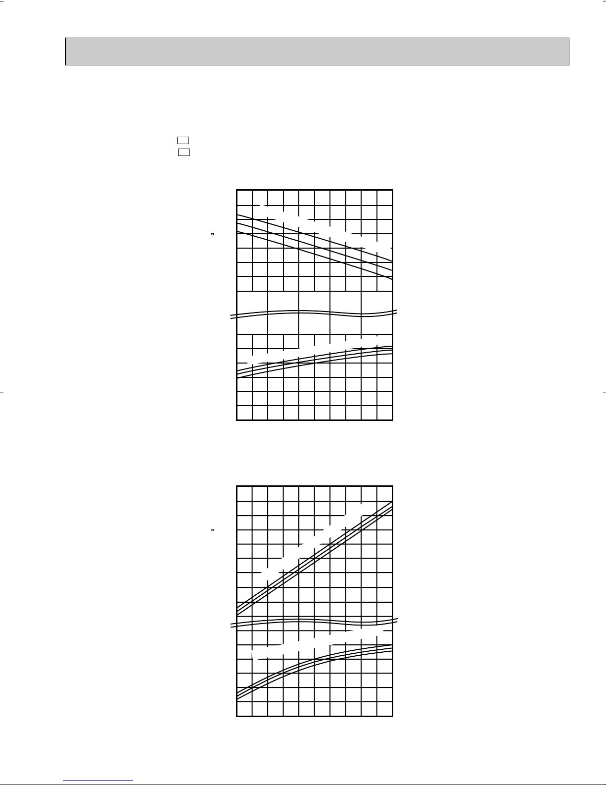
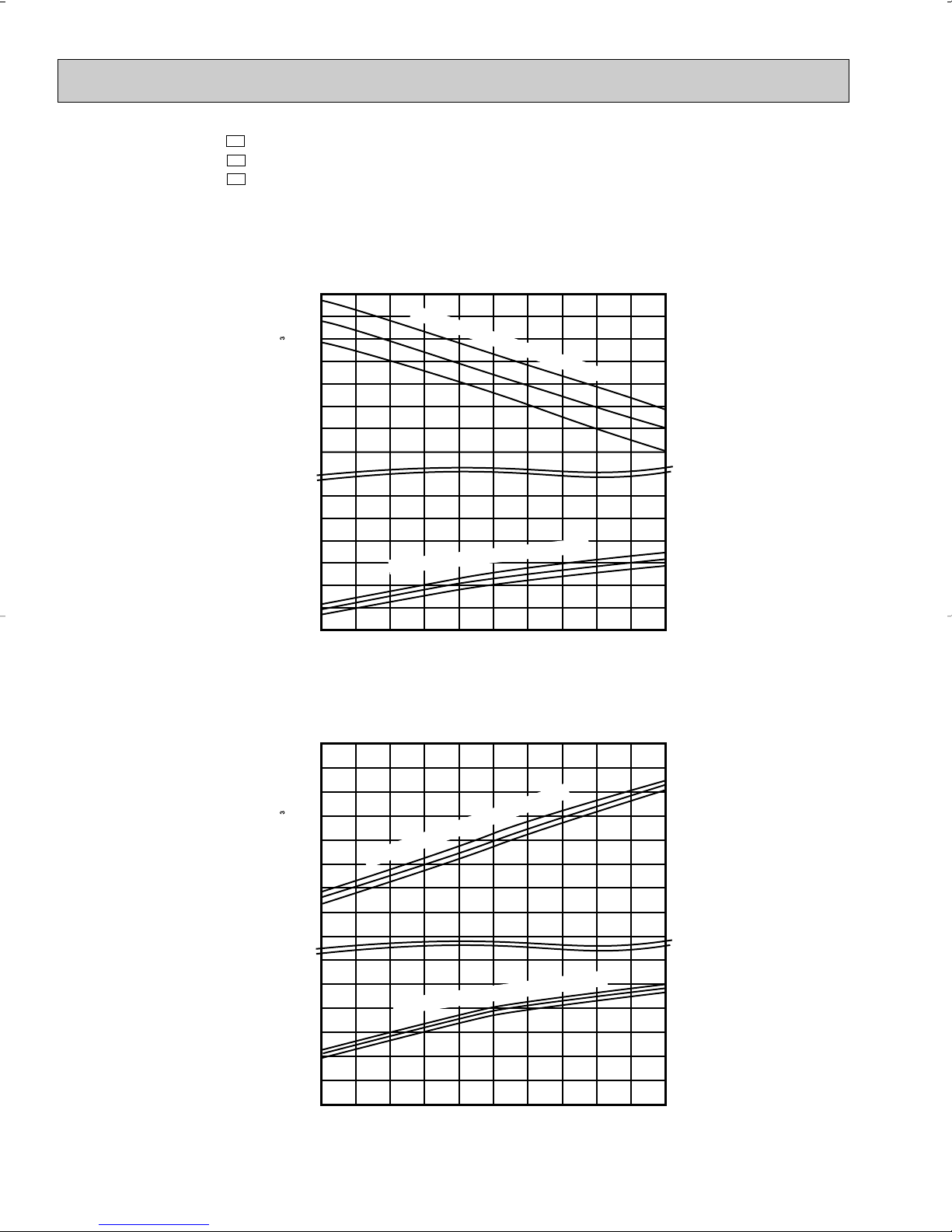
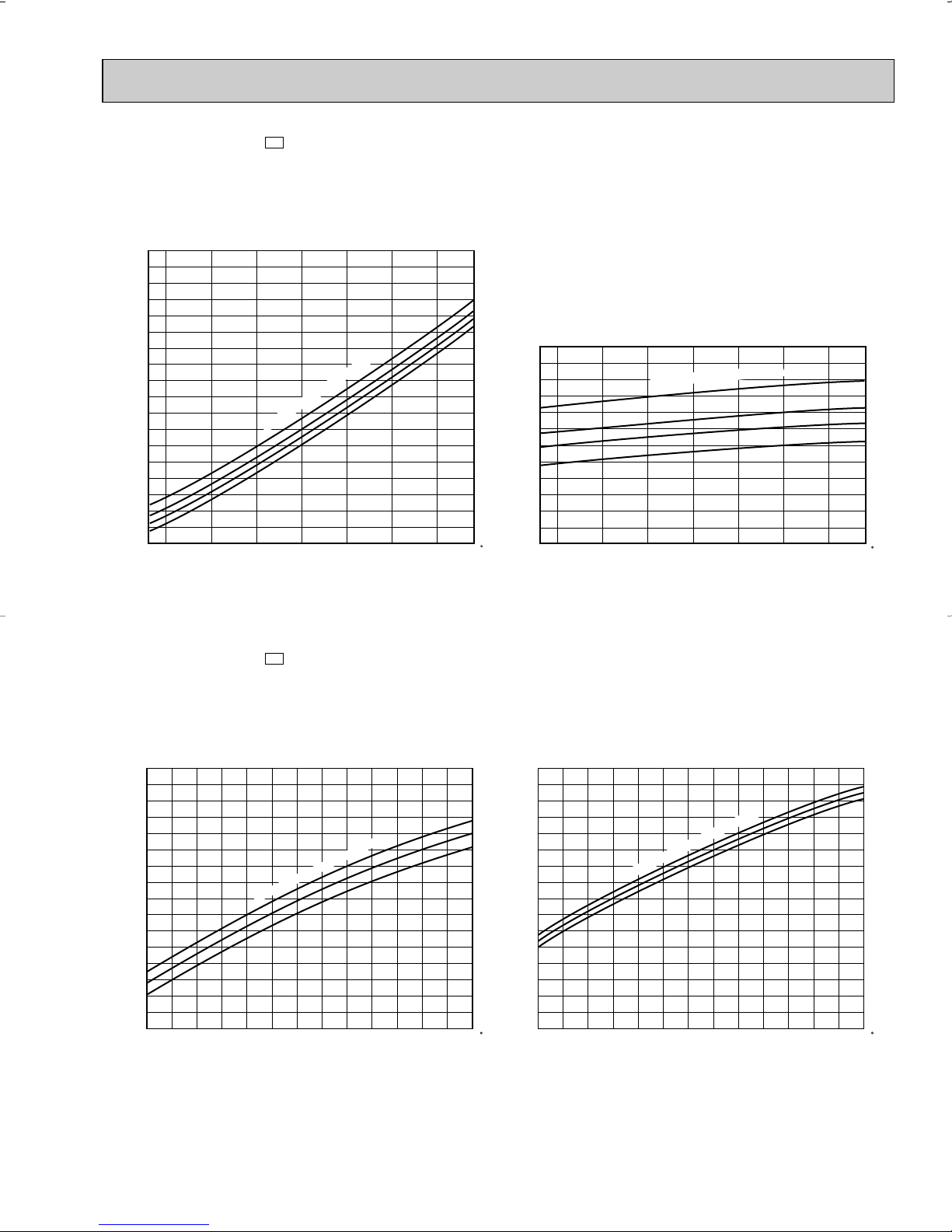
6-2. PERFORMANCE CURVE
71
67
63
71
67
63
65
70
75
75
70
65
Total power consumption (kW) Total capacity ( ✕10 Btu/h)
Outdoor intake air DB temperature (°F)
Indoor intake air WB temperature (
°F)
Indoor intake air WB temperature (
°F)
Cooling
SHF at rating condition = 0.70
= 233CFM
= 0.23
Airflow
Bypass Factor
12
10
8
6
1.2
65 75 85 95 105 115
0.8
0.6
Total power consumption (kW) Total capacity ( ✕10 Btu/h)
Outdoor intake air WB temperature (°F)
Indoor intake air DB temperature (°F)
Indoor intake air DB temperature (
°F)
Heating
= 297CFM
Airflow
12
14
10
8
6
1.1
1.0
15 25 35 45 55
0.8
0.6
0.7
0.9
1.0
NOTE : The curves shows peformance under 230V AC.
As for under 208V AC, refer to PERFORMANCE DATAon page 17 and 18.
MSH09TW
MUH09TW
MSH09TW MUH09TW -
U1
U1
19
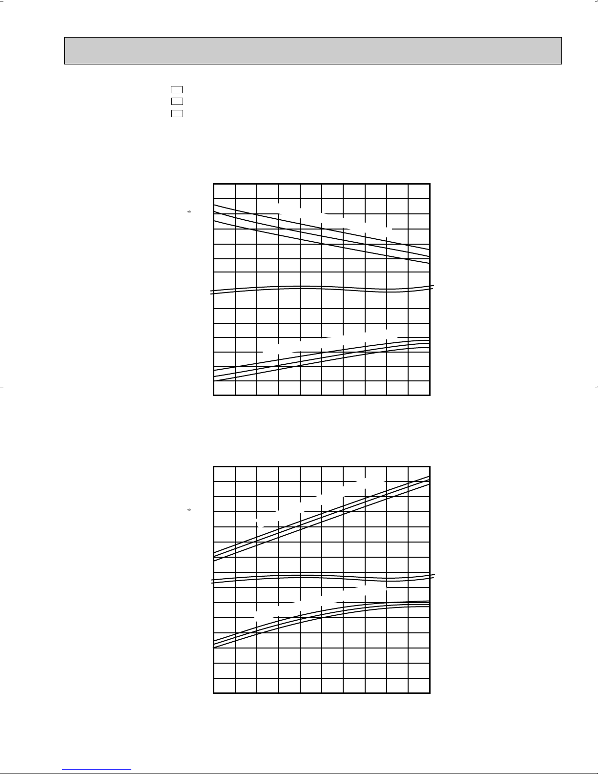
Page 20
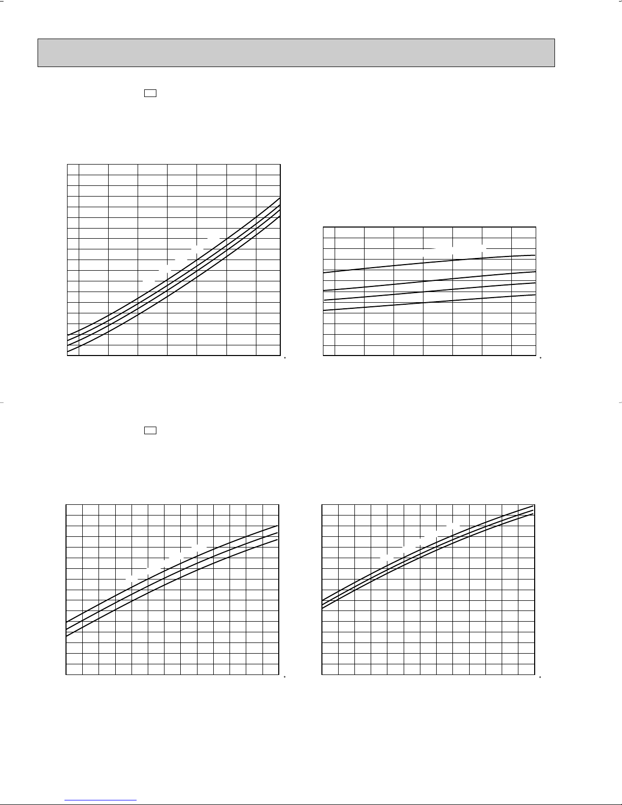
MSH12TN
71
67
63
71
67
63
16
14
10
12
2
1
Indoor intake air WB temperature (
°
F)
Indoor intake air WB temperature (
°
F)
65
70
75
75
70
65
20
16
8
12
1.6
0.6
Cooling
SHF at rating condition = 0.71
= 388CFM
= 0.15
Airflow
Bypass Factor
65 75 85 95 105 115
Total power consumption (kW) Total capacity ( ✕10 Btu/h)
Outdoor intake air DB temperature (°F)
Indoor intake air DB temperature (
°
F)
Heating
= 452CFM
Airflow
15 25 35 45 55
Total power consumption (kW) Total capacity ( ✕10 Btu/h)
Outdoor intake air WB temperature (°F)
0.8
1.0
1.2
1.4
Indoor intake air DB temperature (
°
F)
MUH12TN
MSH12TN MUH12TN MUH12TN -
U1
U1
U2
20
Page 21
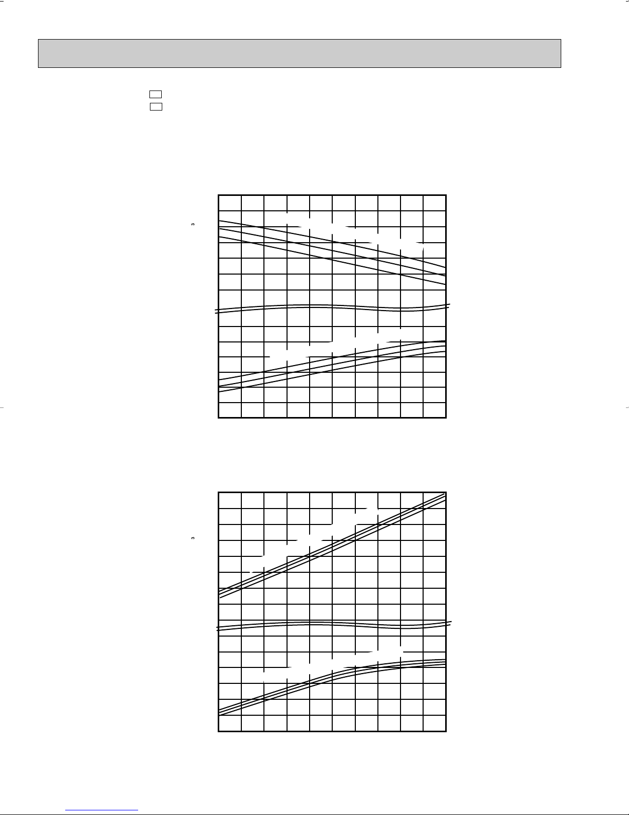
MSH15TN
71
67
63
71
67
63
65
70
75
75
70
65
Indoor intake air WB temperature (
°
F)
Cooling
SHF at rating condition = 0.65
= 367CFM
= 0.22
Airflow
Bypass Factor
65 75 85 95 105 115
Total power consumption (kW) Total capacity ( ✕10 Btu/h)
22
18
14
10
2
Outdoor intake air DB temperature (°F)
Indoor intake air DB temperature (
°
F)
Heating
= 452CFM
Airflow
15 25 35 45 55
Total power consumption (kW) Total capacity ( ✕10 Btu/h)
20
16
8
1.4
0.8
Outdoor intake air WB temperature (°F)
1
12
1.0
1.2
0.6
Indoor intake air DB temperature (
°
F)
Indoor intake air WB temperature (
°
F)
MUH15TN
MSH15TN MUH15TN MUH15TN -
U1
U1
U2
21
Page 22
MSH17TN
71
67
63
71
67
63
65
70
75
75
70
65
Indoor intake air WB temperature (
°
F)
Indoor intake air WB temperature (
°
F)
Cooling
SHF at rating condition = 0.64
= 413CFM
= 0.24
Airflow
Bypass Factor
65 75 85 95 105 115
Total power consumption (kW) Total capacity ( ✕10 Btu/h)
24
20
16
12
2
1
Outdoor intake air DB temperature (°F)
Indoor intake air DB temperature (
°
F)
Indoor intake air DB temperature (
°
F)
Heating
= 491CFM
Airflow
15 25 35 45 55
Total power consumption (kW) Total capacity ( ✕10 Btu/h)
20
16
12
8
2.0
1.0
Outdoor intake air WB temperature (°F)
1.2
1.6
1.4
1.8
MUH17TN
MSH17TN MUH17TN -
U1
U1
22
Page 23
6-3. Condensing pressure
MSH09TW MSH09TW -
U1
(Cooling)
(PSIG)
300
Data is based on the condition of indoor humidity 50%.
Air flow should be set to High speed.
280
260
240
220
200
Condensing pressure
180
160
140
68 70 75 80 85 90 95 100 104(°F)
MSH09TW MSH09TW-
Indoor DB temperature (
Outdoor ambient temperature
U1
(Heating)
°F)
Data is based on the condition of outdoor humidity 75%.
Air flow should be set to High speed.
Data is for heating operation without any frost.
86
(PSIG)
80
75
100
70
90
80
70
60
Suction pressure
50
40
68 70 75 80 85 90 95 100 104(°F)
Indoor DB temperature (°F)
Outdoor ambient temperature
86
80
75
70
(PSIG)
310
300
290
280
270
260
250
240
230
220
210
200
Condensing pressure
190
180
170
160
150
5 10152025303540455055606570(°F)
Indoor DB temperature(
Outdoor ambient temperature
°F)
75
70
65
23
(PSIG)
80
70
60
50
40
30
Suction pressure
20
10
5 10152025303540455055606570(°F)
Indoor DB temperature (°F)
Outdoor ambient temperature
75 70 65
Page 24

MSH12TN MSH12TN(Cooling)
(PSIG)
320
U1
Data is based on the condition of indoor humidity 50%.
Air flow should be set to High speed.
300
280
260
240
220
Condensing pressure
200
180
160
140
68 70 75 80 85 90 95 100 104(°F)
MSH12TN MSH12TN -
Indoor DB temperature (
Outdoor ambient temperature
U1
(Heating)
°F)
Data is based on the condition of outdoor humidity 75%.
Air flow should be set to High speed.
Data is for heating operation without any frost.
86
80
75
70
(PSIG)
100
90
80
70
Suction pressure
60
50
40
Indoor DB temperature (°F)
68 70 75 80 85 90 95 100 104(°F)
Outdoor ambient temperature
86
80
75
70
(PSIG)
310
300
290
280
270
260
250
240
230
220
210
200
Condensing pressure
190
180
170
160
150
5 10152025303540455055606570(°F)
Indoor DB temperature(°F)
Outdoor ambient temperature
(PSIG)
(PSIG)
80
70
60
75
50
70
40
65
30
Suction pressure
Suction pressure
20
10
24
75 70 65
Indoor DB temperature (°F)
Indoor DB temperature (°F)
10 15 20 25 30 35 40 45 50 55 60 65 70(°F)
5
Outdoor ambient temperature
Page 25
MSH15TN MSH15TN(Cooling)
(PSIG)
320
U1
Data is based on the condition of indoor humidity 50%.
Air flow should be set to High speed.
300
280
260
240
220
200
Condensing pressure
180
160
140
68 70 75 80 85 90 95 100 104( F)
MSH15TN MSH15TN(Heating)
Indoor DB temperature (°F)
Outdoor ambient temperature
U1
Data is based on the condition of outdoor humidity 75%.
Air flow should be set to High speed.
Data is for heating operation without any frost.
86
80
75
70
(PSIG)
100
90
80
70
60
Suction pressure
50
40
68 70 75 80 85 90 95 100 104( F)
Indoor DB temperature (°F)
Outdoor ambient temperature
86
80
75
70
(PSIG)
290
280
270
260
250
240
230
220
210
200
Condensing pressure
190
180
170
160
150
510152025303540455055606570( F)
Indoor DB temperature(
Outdoor ambient temperature
°F)
75
70
65
(PSIG)
25
80
70
60
50
40
30
Suction pressure
20
10
510152025303540455055606570( F)
Indoor DB temperature (
Outdoor ambient temperature
°F)
75
70
65
Page 26
MSH17TN MSH17TN(Cooling)
(PSIG)
320
U1
Data is based on the condition of indoor humidity 50%.
Air flow should be set to High speed.
300
280
260
240
220
Indoor DB temperature (°F)
200
Condensing pressure
180
160
140
68 70 75 80 85 90 95 100 104( F)
MSH17TN MSH17TN(Heating)
Outdoor ambient temperature
U1
Data is based on the condition of outdoor humidity 75%.
Air flow should be set to High speed.
Data is for heating operation without any frost.
86
80
75
70
(PSIG)
100
90
80
70
60
Suction pressure
50
40
68 70 75 80 85 90 95 100 104( F)
Indoor DB temperature (°F)
Outdoor ambient temperature
86
80
75
70
(PSIG)
300
290
280
270
260
250
240
230
220
210
200
Condensing pressure
190
180
170
160
150
510152025303540455055606570( F)
Indoor DB temperature(
Outdoor ambient temperature
°F)
75
70
65
(PSIG)
26
80
70
60
50
40
30
Section pressure
20
10
510152025303540455055606570( F)
Indoor DB temperature (
Outdoor ambient temperature
°F)
75
70
65
Page 27
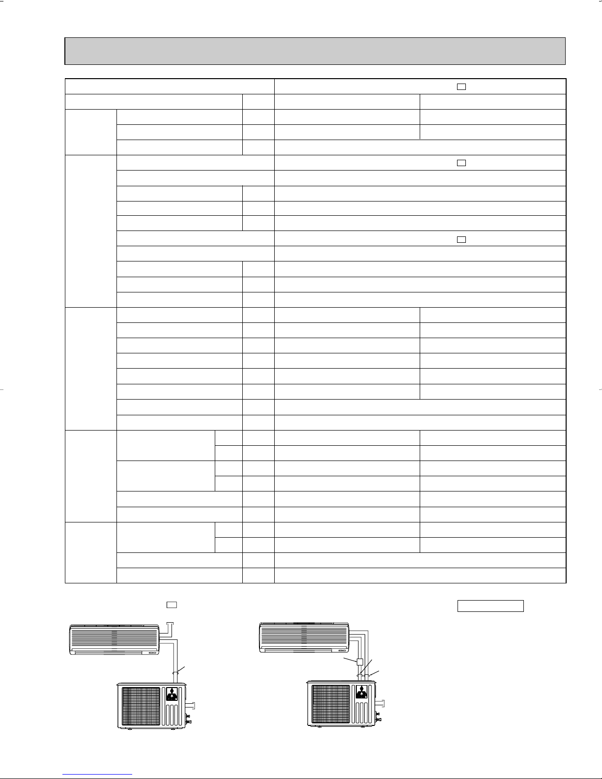
6-4. STANDARD OPERATION DATA
MSH09TW MSH09TW - U1
INDOOR UNIT
115V 60Hz 1[, 2 wires
•Both wirings can be applied to all MODELS.
OUTDOOR UNIT
115V
60Hz 1[, 2 wires
SIGNAL WIRE
2 wires 12V DC
INDOOR UNIT
OUTDOOR UNIT
115V
60Hz 1[, 2 wires
SIGNAL WIRE
2 wires 12V DC
115V 60Hz 1[,
2 wires
Disconnect
switch
Model
Item
Capacity
Total
Electrical
circuit
Refrigerant
circuit
Indoor
unit
Outdoor
unit
SHF
Input
Indoor unit
Power supply (V, phase, Hz)
Input
Fan motor current
Aux. heater current
Outdoor unit
Power supply (V, phase, Hz)
Input
Comp. current
Fan motor current
Condensing pressure
Suction pressure
Discharge temperature
Condensing temperature
Suction temperature
Comp. shell bottom temp
Ref. pipe length
Refrigerant charge (R22)
Intake air temperature
Discharge air temperature
Fan speed (High)
Airflow (High)
Intake air temperature
Fan speed
Airflow
DB
WB
DB
WB
DB
WB
Unit
Btu / h
—
kW
kW
A
A
kW
A
A
PSIG
PSIG
˚F
˚F
˚F
˚F
ft.
—
˚F
˚F
˚F
˚F
rpm
CFM
˚F
˚F
rpm
CFM
Cooling
8,800
0.70
235
70
179
113
52
157
80
67
59
57
950
233(Wet)
95
–
MSH09TW MSH09TW -
0.89
MSH09TW MSH09TW -
115,1,60
0.035
0.34
–
MUH09TW MUH09TW -
115, 1, 60
0.855
6.91
0.59
25
2 lb. 3 oz.
640
985
U1
Heating
10,500
–
U1
U1
223
60
171
110
35
146
70
60
100
–
1,000
297(Dry)
47
43
POWER SUPPLY
27
✻ Control voltage
Power supply voltage to serial
signal circuit is 12V DC.
11
Peak voltage between
and 33+ on in-out terminal
block is 12V DC .
Page 28
Cooling
12,600/12,900
0.71
1.28/1.31
1.233/1.263
5.74/5.21
259
84
194
120
67
177
80
67
57
56
388[Wet]
95
–
Capacity (208/230V)
SHF
Input (208/230V)
Indoor unit
Power supply (V, phase, Hz)
Input
Fan motor current
Aux. heater current
Outdoor unit
Power supply (V, phase, Hz)
Input (208/230V)
Comp. current (208/230V)
Fan motor current
Condensing pressure
Suction pressure
Discharge temperature
Condensing temperature
Suction temperature
Comp. shell bottom temp
Ref. pipe length
Refrigerant charge (R22)
Intake air temperature
Discharge air temperature
Fan speed (High)
Airflow (High)
Intake air temperature
Fan speed (208/230V)
Airflow (208/230V)
Unit
Btu / h
—
kW
kW
A
A
kW
A
A
PSIG
PSIG
˚F
˚F
˚F
˚F
ft.
—
˚F
˚F
˚F
˚F
rpm
CFM
˚F
˚F
rpm
CFM
Cooling
14,300/14,600
0.65
1.35/1.38
1.303/1.333
5.91/5.41
246
80
146
112
58
161
80
67
57
54
367[Wet]
95
–
Heating
14,500/14,800
–
1.25/1.30
1.203/1.253
5.41/5.11
230
57
158
108
33
143
70
60
107
–
452[Dry]
47
43
Heating
13,000/13,500
–
1.18/1.25
1.133/1.203
5.24/5.01
203
58
158
103
36
144
70
60
100
–
452[Dry]
47
43
DB
WB
DB
WB
DB
WB
Item
Model
Total
Electrical
circuit
Refrigerant
circuit
Indoor
unit
Outdoor
unit
MSH12TN MSH12TN -
U1
MSH12TN MSH12TN -
U1
115, 1, 60
0.047
0.41
–
MUH12TN MUH12TN -
U1 U2
208/230, 1, 60
0.36/0.39
25
2 Ib. 12 oz.
1,200
700/740
974/1,034
MSH15TN MSH15TN -
U1
MSH15TN MSH15TN -
U1
115, 1, 60
0.047
0.41
–
MUH15TN MUH15TN -
U1 U2
208/230, 1, 60
0.49
25
3 Ib. 3 oz.
1,200
830/900
1,288/1,394
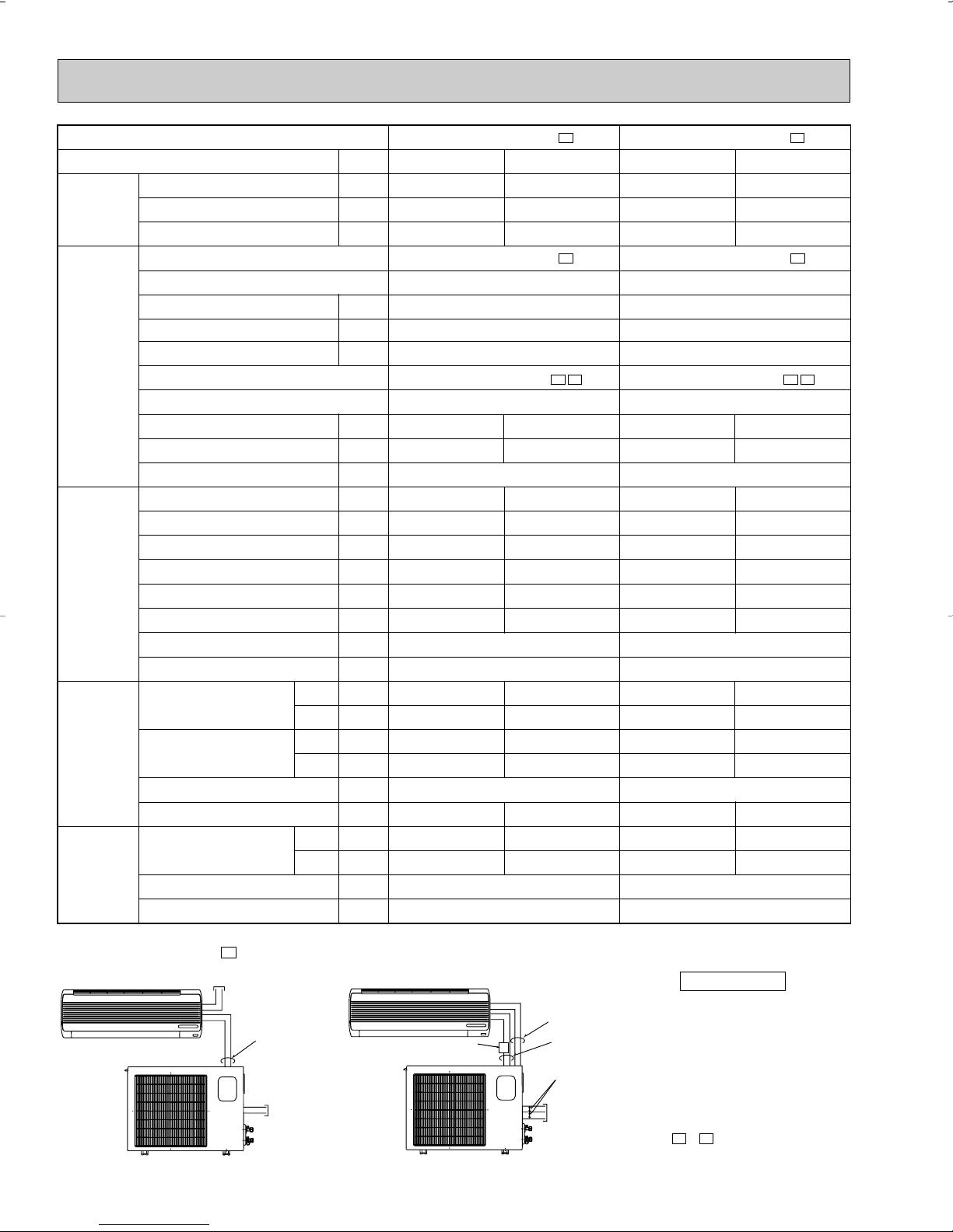
MSH12/15TN MSH12/15TN - U1
INDOOR UNIT
OUTDOOR UNIT
115V 60Hz 1[, 2wires
208/230V 60Hz 1[,
2 wires
SIGNAL WIRE
2 wires 12V DC
INDOOR UNIT
OUTDOOR UNIT
208/230V 60Hz 1[,
3 wires
115V 60Hz 1[,
2 wires
SIGNAL WIRE
2 wires 12V DC
•Both wirings can be applied to all MODELS.
115V
•Outline of MUH12TN( )
is same as one of MUH09TW.
- U1 , - U2
Disconnect
switch
POWER SUPPLY
28
✻ Control voltage
Power supply voltage to serial
signal circuit is 12V DC.
Peak voltage between 11and 33+ on in-out terminal
block is 12V DC .
Page 29
Model
MSH17TN MSH17TN - U1
INDOOR UNIT
OUTDOOR UNIT
115V 60Hz 1[, 2 wires
208/230V 60Hz 1[,
2 wires
SIGNAL WIRE
2 wires 12V DC
INDOOR UNIT
OUTDOOR UNIT
208/230V 60Hz 1[,
3 wires
115V 60Hz 1[,
2wires
SIGNAL WIRE
2 wires 12V DC
•Both wirings can be applied to all MODELS.
115V
Disconnect switch
Item
Capacity (208/230V)
Total
Electrical
circuit
Refrigerant
circuit
SHF
Input (208/230V)
Indoor unit
Power supply (V, phase, Hz)
Input
Fan motor current
Aux. heater current
Outdoor unit
Power supply (V, phase, Hz)
Input (208/230V)
Comp. current (208/230V)
Fan motor current
Condensing pressure
Suction pressure
Discharge temperature
Condensing temperature
Suction temperature
Comp. shell bottom temp
Ref. pipe length
Refrigerant charge (R22)
Intake air temperature
Indoor
unit
Outdoor
unit
Discharge air temperature
Fan speed (High)
Airflow (High)
Intake air temperature
Fan speed (208/230V)
Airflow (208/230V)
POWER SUPPLY
Unit
Btu / h
—
kW
kW
A
A
kW
A
A
PSIG
PSIG
˚F
˚F
˚F
˚F
ft.
—
DB
WB
DB
WB
DB
WB
˚F
˚F
˚F
˚F
rpm
CFM
˚F
˚F
rpm
CFM
Cooling
16,000/16,200
0.64
1.56/1.58
1.506/1.526
6.69/6.19
243
77
165
113
48
150
80
67
56
54
413[Wet]
95
–
MSH17TN MSH17TN -
MSH17TN MSH17TN -
115,1,60
0.054
0.47
–
MUH17TN MUH17TN -
208/230, 1, 60
0.61
25
4 lb. 14 oz.
1,290
740/800
1,606/1,730
✻ Control voltage
Power supply voltage to serial
signal circuit is 12V DC.
Peak voltage between 11and 33+ on in-out terminal
block is 12V DC .
U1
Heating
16,800/17,200
–
1.50/1.57
U1
U1
1.446/1.516
6.39/6.09
242
63
162
112
35
144
70
60
109
–
491[Dry]
47
43
29
Page 30
Capacity
SHF
Input
Outdoor unit
Power supply (V, phase, Hz)
Input
Comp. current
Fan motor current
Condensing pressure
Suction pressure
Discharge temperature
Condensing temperature
Suction temperature
Comp. shell bottom temp
Ref. pipe length
[Total pipe length for multi-system]
Refrigerant charge (R22)
Intake air temperature
Fan speed (208/230V)
Airflow (208/230V)
Unit
Btu / h
—
kW
kW
A
A
PSIG
PSIG
˚F
˚F
˚F
˚F
ft.
—
˚F
˚F
rpm
CFM
Heating
28,600
–
2.8
2.8
12.3
219
47
169
26
144
47
43
DB
WB
Item
Model
Total
Electrical
circuit
Refrigerant
circuit
Outdoor
unit
Cooling
28,400
–
3.8
3.8
17.1
300
65
194
41
150
95
–
MXZ30TN MXZ30TN2
208/230, 1, 60
0.60
127
82 [197]
8 lb. 10 oz.
630/675
1,764/1,906
MXZ30TN MXZ30TN2
INDOOR UNIT
MXZ30TN
MXZ30TN2
115V 60Hz
1[, 2 wires
208/230V 60Hz 1[,
2 wires
SIGNAL WIRE
2 wires 12V DC
INDOOR UNIT
INDOOR UNIT
115V 60Hz
1[, 2 wires
115V 60Hz
1[, 2 wires
POWER SUPPLY
30
✻ Control voltage
Power supply voltage to serial
signal circuit is 12V DC.
Peak voltage between 11and 33+ on in-out terminal
block is 12V DC .
Page 31

6-5. OPERATING RANGE
MUH09TW
MUH12TN
MUH15TN
MUH17TN
MXZ30TN
MXZ30TN2
Indoor unit
Outdoor unit
Rating
115V 60Hz 1[
208/230V 60Hz 1[
Guaranteed Voltage
MSH09TW
MSH12TN
MSH15TN
MSH17TN
Model
MUH09TWMUH12TN-
MUH12TNMUH15TNMUH15TNMUH17TN-
MSH09TWMSH12TNMSH15TNMSH17TN-
U1
U1
U1
U1
U1
U1
U2
U1
U2
U1
Min. 103V
Max. 127V
115V
Min. 198V Max. 253V
208V
230V
78%
—
w
At Intermediate compressor Speed
=("Cooling rated compressor speed" - "minimum compressor speed") / 3 + "minimum compressor speed".
Function
Cooling
Heating
Standard temperature
Maximum temperature
Minimum temperature
Maximum humidity
Standard temperature
Maximum temperature
Minimum temperature
DB (˚F)
80
95
67
70
80
70
WB (˚F)
67
71
57
60
67
60
Indoor
DB (˚F)
95
115
67
47
75
17
WB (˚F)
—
—
—
43
65
15
Outdoor
Condition
Intake air
temperature
Function
Cooling
Heating
"A" Cooling Steady State
at rated compressor Speed
"B-2" Cooling Steady State
at rated compressor Speed
"B-1" Cooling Steady State
at minimum compressor Speed
Low ambient Cooling Steady State
at minimum compressor Speed
Intermediate Cooling Steady State
At Intermediate compressor Speedw
Standard Rating-Heating
at rated compressor Speed
Low temperature Heating
at rated compressor Speed
Max temperature Heating
at minimum compressor Speed
High temperature Heating
at minimum compressor Speed
Frost Accumulation
at rated compressor Speed
Frost Accumulation
at Intermediate compressor Speedw
DB (˚F)
80
80
80
80
80
70
70
70
70
70
70
WB (˚F)
67
67
67
67
67
60
60
60
60
60
60
Indoor
DB (˚F)
95
82
82
67
87
47
17
62
47
35
35
WB (˚F)
(75)
(65)
(65)
(53.5)
(69)
43
15
56.5
43
33
33
Outdoor
Condition
Intake air
temperature
MSH09TW
MSH12TN
MSH15TN
MSH17TN
MSH09TWMSH12TNMSH15TNMSH17TN-
U1
U1
U1
U1
MXZ30TN MXZ30TN2
(1) POWER SUPPLY
(2) OPERATION
31
Page 32

6-6. OUTLET AIR SPEED AND COVERAGE RANGE
Model
MSH09TW MSH09TW-
MSH12TN MSH12TN-
MSH15TN MSH15TN-
MSH17TN MSH17TN-
U1
U1
U1
U1
Mode
HEAT
COOL
HEAT
COOL
HEAT
COOL
HEAT
COOL
297
279
233
452
452
388
452
452
367
491
491
413
15.8
14.9
12.4
18.2
18.2
15.6
18.2
18.2
14.8
19.7
19.7
16.6
22.3
21.0
17.6
29.2
29.2
25.2
29.2
29.2
23.9
31.7
31.7
26.8
Air flow
(CFM)
Air speed
(ft./sec.)
Coverage
range (ft.)
Function
Dry
Dry
Wet
Dry
Dry
Wet
Dry
Dry
Wet
Dry
Dry
Wet
MSH09TW MSH09TWMUH09TW MUH09TWMSH12TN MSH12TNMUH12TN MUH12TN-
MUH12TNMSH15TN MSH15TNMUH15TN MUH15TN-
MUH15TNMSH17TN MSH17TNMUH17TN MUH17TN-
Outdoor unit
precharged
(up to 25ft.)
2 lb. 3 oz.
2 lb. 12 oz.
3 lb. 3 oz.
4 lb. 14 oz.
25ft.
0
30ft.
2.68
35ft.
5.36
Refrigerant piping length (one way)
40ft.
8.04
45ft.
10.72
49ft.
12.86
Model
U1
U1
U1
U1
U2
U1
U1
U2
U1
U1
6-7. ADDITIONAL REFRIGERANT CHARGE (R22(oz.))
● The air coverage range is the figure up
to the position where the air speed is
1 ft./sec., when air is blown out
horizontally from the unit properly at the
High speed position.
The coverage range should be used only
as a general guideline since it varies
according to the size of the room and
furniture arranged inside the room.
W MXZ30TN and MXZ30TN2 do not have the necessity of additional refrigerant.
32
Page 33

MXZ30TN MXZ30TN2
Wet-and dry-bulb
thermometers
Wet-and dry-bulb
thermometers
09 class
(32Hz)
51.4
49.8
48.2
46.6
45.0
43.5
49.8
48.4
46.8
45.3
44.1
42.6
51.4
49.6
48.0
46.6
45.0
43.5
47.3
46.0
44.8
43.7
424
41.4
18 class
(73Hz)
15 class
(73Hz)
12 class
(46Hz)
80 85 90 95 100 105 110
80 85 90 95 100 105 110
79
75
72
68
64
79
75
72
68
64
Indoor unit class
(Inverter output
frequency)
Indoor air WB temperature
difference (degree)
72.0
68.7
65.7
62.6
59.5
56.5
53.4
50.4
74.7
71.4
68.2
64.8
61.5
58.3
55.0
51.6
86.2
82.0
77.9
73.8
69.6
65.3
61.2
57.8
68.4
65.7
62.8
59.9
57.2
54.3
51.6
48.7
09 class
(36Hz)
12 class
(65Hz)
15 class
(80Hz)
17 class
(80Hz)
14
20
30
40
50
59
68
79
60
14
20
30
40
50
60
59
68
79
Indoor unit class
(Inverter output
frequency)
Indoor air DB temperature
difference (degree)
The standard data contained in these specifications apply only to the operation of the air conditioner under normal conditions,
since operating conditions vary according to the areas where these units are installed. The following information has been provided to clarify the operating characteristics of the air conditioner under the conditions indicated by the performance curve.
(1) GUARANTEED VOLTAGE
198 ~ 264V
(2) AIR FLOW
Air flow should be set at MAX.
(3) MAIN READINGS
(1) Indoor intake air wet-bulb temperature : °FWB
(2) Indoor outlet air wet-bulb temperature : °FWB
(3) Outdoor intake air dry-bulb temperature : °FDB
(4) Total input: W
(5) Indoor intake air dry-bulb temperature : °FDB
(6) Outdoor intake air wet-bulb temperature : °FWB
(7) Total input : W
Indoor air wet/dry-bulb temperature difference on the left side of the chart on this page shows the difference between the
indoor intake air wet/dry-bulb temperature and the indoor outlet air wet/dry-bulb temperature for your reference at service.
Cooling
}
Heating
}
How to measure the indoor air wet-bulb/dry-bulb temperature difference
1. Attach at least 2 sets of wet-and dry-bulb thermometers to the indoor air intake as shown in the figure, and at least 2 sets
of wet-and dry-bulb thermometers to the indoor air outlet. The thermometers must be attached to the position where air
speed is high.
2. Attach at least 2 sets of wet-and dry-bulb thermometers to the outdoor air intake.
Cover the thermometers to prevent direct rays of the sun.
3. Check that the air filter is cleaned.
4. Open windows and doors of room.
5. Press the EMERGENCY OPERATION switch once(twice) to start the EMERGENCY COOL(HEAT) MODE.
6. Compressor starts running at 33Hz (COOL) or 45Hz (HEAT). The frequency at each operation mode is fixed.
7. When system stabilizes after more than 15 minutes, measure temperature and take an average temperature.
8. 10 minutes later, measure temperature again and check that the temperature does not change.
INDOOR UNIT OUTDOOR UNIT
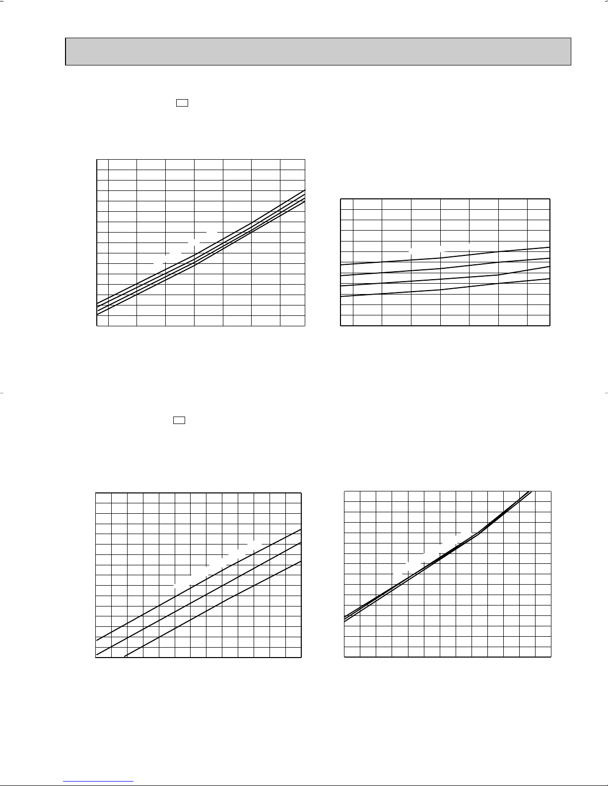
6-8. CAPACITY AND THE INPUT CURVES
33
Page 34

6-9. Capacity and input correction by means of inverter output frequency
0 50 100
0.5
1.0
1.5
2.0
0 50 100
0.5
1.0
1.5
2.0
0 50 100
0.5
1.0
1.5
2.0
0 50 100
0.5
1.0
1.5
2.0
0 50 100
0.5
1.0
1.5
2.0
0 50 100
0.5
1.0
1.5
2.0
0 50 100
0.5
1.0
1.5
2.0
0 50 100
0.5
1.0
1.5
2.0
0 50 100
0.5
1.0
1.5
2.0
0 50 100
0.5
1.0
1.5
2.0
0 50 100
0.5
1.0
1.5
2.0
0 50 100
0.5
1.0
1.5
2.0
0 50 100
0.5
1.0
1.5
2.0
0 50 100
0.5
1.0
1.5
2.0
0 50 100
0.5
1.0
1.5
2.0
0 50 100
0.5
1.0
1.5
2.0
<COOL>Capacity
Frequency
Hz
Frequency
<COOL>Total input
Hz
<HEAT>Capacity
Frequency
Hz
Frequency
<HEAT>Total input
Hz
<COOL>Capacity
Frequency
Hz
Frequency
<COOL>Total input
Hz
<HEAT>Capacity
Frequency
Hz
Frequency
<HEAT>Total input
Hz
<COOL>Capacity
Frequency
Hz
Frequency
<COOL>Total input
Hz
<HEAT>Capacity
Frequency
Hz
Frequency
<HEAT>Total input
Hz
1. 09-class unit in single operation
2. 12-class unit in single operation
3. 15-class unit in single operation
<COOL>Capacity
Frequency
Hz
Frequency
<COOL>Total input
Hz
<HEAT>Capacity
Frequency
Hz
Frequency
<HEAT>Total input
Hz
4. 17-class unit in single operation
(OUTDOOR UNIT:MXZ30TN MXZ30TN2)
34
Page 35

6-10. Outdoor low pressure and outdoor unit current
65 70 75 80 85 90 95 100 105 110 115
50
60
70
80
90
100
Ambient temperature(°F)
(°F)
86
80
75
70
Indoor DB temperature(°F)
65 70 75 80 85 90 95 100 105 110 115
0.0
1.0
2.0
3.0
4.0
5.0
6.0
Ambient temperature(°F)
(°F)
15 20 25 30 35 40 45 50 55 60 65 70 75
4.0
5.0
6.0
7.0
8.0
9.0
Outdoor ambient temperature(°F)
Outdoor low pressure
Outdoor unit current (A)
Outdoor unit current (A)
45Hz
(PSIG)
33Hz
33Hz
65
75
70
86
80
75
70
Indoor DB temperature(°F)
Indoor DB temperature(°F)
1. 09-class unit in single operation (OUTDOOR UNIT : MXZ30TN MXZ30TN2)
(1) COOL operation
1Data is based on the condition of indoor
humidity 50%
2Air flow speed : High
3Inverter output frequency : 33Hz
(2) HEAT operation
①
Data is based on the condition of outdoor
humidity 75%.
➁
Set air flow to High speed.
➂
Inverter output frequency is 45Hz.
<How to work fixed-frequency operation>
1.Set emergency switch to COOL or HEAT.The switch is located on indoor unit.
2.Press emergency run ON/OFF button.
3.Compressor starts running at 33Hz (COOL) or 45Hz (HEAT).
4.Indoor fan runs at High speed and continues for 30 minutes.
5.To cancel this operation,press emergency run ON/OFF button
or any button on remote controller.
35
Page 36

2. 12-class unit in single operation (OUTDOOR UNIT : MXZ30TN MXZ30TN2)
65 70 75 80 85 90 95 100 105 110 115
65
70
75
80
85
90
95
100
Ambient temperature(°F)
(°F)
86
80
75
70
86
80
75
70
15 20 25 30 35 40 45 50 55 60 65 70 75
4.0
5.0
6.0
7.0
8.0
9.0
Outdoor ambient temperature(°F)
65 70 75 80 85 90 95 100 105 110 115
0.0
1.0
2.0
3.0
4.0
5.0
6.0
Ambient temperature(°F)
(°F)
(PSIG)
Outdoor low pressure
Outdoor unit current (A)
Outdoor unit current (A)
45Hz
33Hz
33Hz
65
70
75
Indoor DB temperature(°F)
Indoor DB temperature(°F)
Indoor DB temperature(°F)
(1) COOL operation
1Data is based on the condition of indoor
humidity 50%
2Air flow speed : High
3Inverter output frequency : 33Hz
<How to work fixed-frequency operation>
1.Set emergency switch to COOL or HEAT.The switch is located on indoor unit.
2.Press emergency run ON/OFF button.
3.Compressor starts running at 33Hz (COOL) or 45Hz (HEAT).
4.Indoor fan runs at High speed and continues for 30 minutes.
5.To cancel this operation,press emergency run ON/OFF button
or any button on remote controller.
(2) HEAT operation
①
Data is based on the condition of outdoor
humidity 75%.
➁
Set air flow to High speed.
➂
Inverter output frequency is 45Hz.
36
Page 37

4. 15-class unit in single operation (OUTDOOR UNIT : MXZ30TN MXZ30TN2)
65 70 75 80 85 90 95 100 105 110 115
65
70
75
80
85
90
95
100
Ambient temperature(°F)
(°F)
86
80
75
70
86
80
75
70
15 20 25 30 35 40 45 50 55 60 65 70 75
4.0
5.0
6.0
7.0
8.0
9.0
Outdoor ambient temperature(°F)
65 70 75 80 85 90 95 100 105 110 115
0.0
1.0
2.0
3.0
4.0
5.0
6.0
Ambient temperature(°F)
(°F)
(PSIG)
Outdoor low pressure
Outdoor unit current (A)
Outdoor unit current (A)
45Hz
33Hz
33Hz
65
70
75
Indoor DB temperature(°F)
Indoor DB temperature(°F)
Indoor DB temperature(°F)
(1) COOL operation
1Data is based on the condition of indoor
humidity 50%
➁
Air flow speed : High
➂
Inverter output frequency : 33Hz
<How to work fixed-frequency operation>
1.Set emergency switch to COOL or HEAT.The switch is located on indoor unit.
2.Press emergency run ON/OFF button.
3.Compressor starts running at 33Hz (COOL) or 45Hz (HEAT).
4.Indoor fan runs at High speed.
5.To cancel this operation,press emergency run ON/OFF button
or any button on remote controller.
(2) HEAT operation
①
Data is based on the condition of outdoor
humidity 75%
➁
Set air flow to High speed.
➂
Inverter output frequency is 45Hz.
37
Page 38

5. 17-class unit in single operation (OUTDOOR UNIT : MXZ30TN MXZ30TN2)
65 70 75 80 85 90 95 100 105 110 115
65
70
75
80
85
90
95
100
Ambient temperature(°F)
(°F)
15 20 25 30 35 40 45 50 55 60 65 70 75
4.0
5.0
6.0
7.0
8.0
9.0
Outdoor ambient temperature(°F)
65 70 75 80 85 90 95 100 105 110 115
1.0
2.0
3.0
4.0
5.0
6.0
7.0
Ambient temperature(°F)
(°F)
(PSIG)
Outdoor low pressure
Outdoor unit current (A)
Outdoor unit current (A)
45Hz
33Hz
33Hz
86
80
75
70
75
70
65
Indoor DB temperature(°F)
Indoor DB temperature(
°F)
Indoor DB temperature(°F)
(1) COOL operation
1Data is based on the condition of indoor
humidity 50%
➁
Air flow speed : High
➂
Inverter output frequency : 33Hz
<How to work fixed-frequency operation>
1.Set emergency switch to COOL or HEAT.The switch is located on indoor unit.
2.Press emergency run ON/OFF button.
3.Compressor starts running at 33Hz (COOL) or 45Hz (HEAT).
4.Indoor fan runs at High speed.
5.To cancel this operation,press emergency run ON/OFF button
or any button on remote controller.
(2) HEAT operation
①
Data is based on the condition of outdoor
humidity 75%
➁
Set air flow to High speed.
➂
Inverter output frequency is 45Hz.
38
Page 39

7
OUTLINES AND DIMENSIONS
MSH09TW MSH09TW -
INDOOR UNIT
10-15/16
2-5/16
6-3/8
Wireless remote controller
U1
Installation plate
Indoor unit
32-3/16
33-1/2
6-1/224-3/42-1/4
3/4
MUH09TW MUH12TN MUH09TW MUH12TN - MUH12TN -
U2U1
3-5/16
1-5/8
3-1/4
Air in
U1
12-13/16 12-13/16
3/16
7-7/16
1/4 or more
2-5/8
3-15/16
Air out
3-1/16
REQUIRED SPACE
4 in. or more
6-5/8
1/8
4-5/8
Wall hole [2-9/16
Installation plate
Liquid line [1/4 19-11/16
Gas line [3/8 16-15/16
{
Insulation [1-7/16 O.D
[13/16 I.D
Drain hose [5/8
(Connected part O.D)
Insulation [1-1/8
Outdoor
unit
3/16
9-1/8
10-11/16
1-5/8
4 in. or more
Unit: inch
4 in.or more
OUTDOOR UNIT
Air in
12-19/32
1-1/4
4-9/32
Air in
Drainage
3holes [1-5/16
21-1/4
10-1/4
1-9/16
13/32
5-25/32
4-13/16
4-11/32
Airout
19-22/32
30-23/32
10-1/32
11-7/32
31/32
6-3/32
2-29/32
12-19/32
3-17/32
4-3/32
39
Service panel
Grounding
Service panel
Liquid refrigerant
pipe joint
Refrigerant pipe
(flared) [1/4
35-
43-
Gas refrigerant
pipe joint
Refrigerant pipe
(flared) [3/8 (MUH09TW
[1/2 (MUH12TN
terminal
16 in. or more
Lock nut
NOTE: Do not wire 12V DC and 115V AC
in same conduit hole.
)
)
14 in. or more
Connector
Conduit
cover
Page 40

MSH12TN MSH15TN MSH17TN MSH12TN - MSH15TN - MSH17TN -
INDOOR UNIT
39-3/16
4holes 7/16 O 13/16
5-7/8 25-1/2 8-9/16
1-9/16
2-3/8
Indoor unit
U1U1U1
Unit: inch
13/16
39-15/16
12-5/8
7-1/230-1/21-15/16
2-5/16
6-3/8
Wireless remote controller
3/4
MUH15TN MUH15TN - MUH15TN -
OUTDOOR UNIT
Drainage
hole [5/8
1-3/8
13-31/32
13-3/4
Air in
13/16
Installation plate
Air in
U2U1
Air out
17-11/16
17-11/16
13-7/817-1/4
3/167-1/2
Installation plate
Liquid line [ 5/16 19-11/16
Gas line [1/2 16-15/16
{
Insulation [ 1-15/16 O.D
Drain hose [
Insulation [ 1-1/8
4 in.
10
10-13/16
Wall hole [2-15/16
[ 1-1/8 I.D
5/8
4 in.
1/8 11-11/16
4 in.
3-17/32
9-3/4
Air in
Drainage
3holes [1-5/16
23-13/16
11-1/2
13/16
Air out
7-3/16
19-11/16
33-7/16
1-15/16
11-7/16
1-3/16
6-3/16
2-15/16
12-3/16
3-15/16
40
13-9/16
6-5/16
20 in.
Service panel
Liquid refrigerant
pipe joint
Refrigerant pipe
(flared) [1/4
35-
30-
Gas refrigerant
pipe joint
Rfrigerant pipe
(flared) [5/8
NOTE: Do not wire12V DC and
14 in.
Lock nut
Connector
Conduit
cover
115V AC in same conduit hole.
Page 41

MUH17TN MUH17TN -
OUTDOOR UNIT
U1
Unit: inch
8
upper clearance.
Note:Allow adequate
1/2
1/2
11/169/16
Air intake
19-11/16
7-9/32 7-9/32
4
Front opening
14-1/4
13
1-9/161-1/16
Air intake
36
1/2
Air outlet
(for N.E.C)
Service space
36
1-3/4
Refrigerant pipe
(Flared) 1/4
Refrigerant pipe
(Flared) 5/8
33-1/2
21-3/4
11-7/8
Handie for moving
Service panel
Ground
terminal
Terminal block for indoor and outdoor unit connection
Terminal block for power line
34-1/4
20-5/18
13-7/8
13-7/4
15-7/8
7-1/18
17-3/18
2-1/16
Knock out holes for
power line 1-1/16
4-3/4
2-3/8
Knock out hole
for front piping
(refrigerant. drainage
and wiring)
Knock out hole for
right piping
2-3/820-5/81-9/16
1/5/16
4-1/8
1/2x7/8 Oval hoies
(standard bolt W3/8(M10)
1 max.
3-1/8
R13/16
R13/16
(refrigerant. drainage
and wiring)
1-3/4
1-5/8
Bottom piping hole
Drain hole
Standard bolt length
2-9/16
Front right piping holes-
detail figures
11/16
R1/4
1/2
2-U-shaped
notched
holes
Drain hole
8
40
The upper side must be open.
For 10 units or less
1/2
(Concentrated installation)
Outdoor Unit-Necessary surrouding clearance
4
1
11-5/8
Outlet guide
installation hole
Handle for
moving
41
Handle for moving
Rear fresh
air intake
Side air intake
2
Conduit hole
1
NOTE: Do not wire12V DC and 115V AC in same conduit hole.
Rear piping hole
3-3/4
5-7/16
Page 42

MXZ30TN MXZ30TN2
Lock nut
Conduit cover
Connector
OUTDOOR UNIT
Base bolt length
Less than
1
Veranda
Base
Rubber cushion
13/32 1-3/812-19/32
19-11/16
7-7/8 7-7/8
Air in
Air out
35-7/16
2-U-shape notched holes
(Base bolt M10)
1-1/16
Air in
13-31/32
1-9/16
2-15/32 ✕ 1-13/32 Oval hole
(Base bolt M10)
Unit: inch
15-1/4
[
9.52 (flared) 3/8 (B, C unit)
12.7 (flared) 1/2 (A unit)
[
Handle for
moving
1.Installation space
Note : Leave front and both sides
clearance fully.
Note : Leave front and overhead
clearance fully.
Air in
19-11/16
Air in
29/32
More than
1-5/16
More than
3-15/16
More than
7-7/8
18-1/8
12-15/32
3-15/32
35-7/16
29/32
Note : Obstacle on front and rear side only.
The unit can be used by attaching an optional
outdoor outlet guide (MAC-855SG)
(but both sides and the top are opend.)
Liquid pipe
[
6.35 (flared) 1/4
2.Service space
C unit connection
B unit connection
A unit connection
More than
3-15/16
More than
3-15/16
Note : Leave front, overhead and
both clearance fully.
More than
13-25/32
More than
19-11/16
42
More than
3-15/16
More than
13-25/32
More than
13-25/32
Service space
More than
1911/16
Page 43

8
WIRING DIAGRAM
MSH09TW
MODEL WIRING DIAGRAM
INDOOR UNIT
TB
TO OUTDOOR
UNIT
CONNECTING
WIRES
12V DC
FROM OUTDOOR
UNIT
CONNECTING
WIRES
POWER
(
)
SUPPLY
115V
1 phase
60Hz
TO OUTDOOR
UNIT
CONNECTING
WIRE
TO OUTDOOR
UNIT
CONNECTING
WIRES
12V DC
POWER SUPPLY
115V 1 phase
60Hz
SYMBOL
C11
F11
HIC1
MF
NOTE:1. About the outdoor side electric wiring, refer to the outdoor unit electric wiring diagram for servicing.
INDOOR FAN CAPACITOR
FUSE(3A)
DC/DC CONVERTER
INDOOR FAN MOTOR(INNER FUSE)
2. Use copper conductors only.(For field wiring)
3. Symbols below indicate;
: Terminal block, : Connector
w
FOR MULTI SYSTEM
NAME
MUH09TW
OUTDOOR UNIT
ORN
3+
1-
N
L1
VLT
BLK
RED
CN
151
CN201
TAB12
LD101T
5
3+
1-
N
L1
w A disconnect may be required by local code.
MV
POWER MONITOR,
RECEIVER
P.C.BOARD
SYMBOL
MV
NR11
RT11
RT12
VANE MOTOR
VARISTOR
ROOM TEMPERATURE THERMIST OR
INDOOR COIL THERMISTOR
MODEL WIRING DIAGRAM
FROM INDOOR UNIT
CONNECTING
WIRE
TB2
+
1
ORN
VLT
-
BLK
RED
GRN/YLW
RED
RED
BLK
FROM INDOOR UNIT
CONNECTING WIRES
12V DC
TO INDOOR UNIT
CONNECTING
WIRES
115V
1 phase 60Hz
POWER
SUPPLY
115V
1 phase 60Hz
GROUND
3
1
N
L
TB1
L1
N
1
2
3
4
ELECTRONIC CONTROL P.C. BOARD
5
REMOTE
CONTROLLER
NAME NAME
CN730
1
3
TAB20
DSAR
RT61
F61
IC881
TRANS
52C
43
21S4
CN721CN661
X62
NR61
DEICER P.C.BOARD
BLK
HIC1
TRANS
F11
SYMBOL
X62
SR61
C1
NR11
SR141
SR141
TB
CN711
C65
WHT
RED
BLK
CN
112
CN
111
3
CN
121
1
C11
2
3
CN211
SOLID STATE RELAY
TERMINAL BLOCK
MF
RED
1
WHT
2
3
BLK
4
C
MC
R
S
RT12
RT11
BLK
1
GRY
2
YLW
3
BRN
WHT
RED
MF
4
5
6
SG79J022H01
SYMBOL
C1
COMPRESSOR CAPACITOR
C65
DSAR
F61
IC881
NOTE:1. About the indoor side electric wiring, refer to the indoor unit electric wiring diagram for servicing.
OUTDOOR FAN CAPACITOR
SURGE ABSORBER
FUSE(2A)
DC/DC CONVERTER
2. Use copper conductors only.(For field wiring)
3. Symbols below indicate;
: Terminal block, : Connector
NAME
SYMBOL
MC
MF
NR61
RT61
SR61
NAME NAME
COMPRESSOR(INNER PROTECTOR)
OUTDOOR FAN MOTOR(INNER PROTECTOR)
VARISTOR
DEFROST THERMISTOR
SOLID STATE RELAY
43
SYMBOL
TB1
TB2
X62
21S4
52C
TERMINAL BLOCK
TERMINAL BLOCK
R.V. COIL RELAY
R.V. COIL
COMPRESSOR CONTACTOR
VG79B007H01
Page 44

RED
ORN
BLK
L1
N
TB
1-
3+
VLT
5
REMOTE
CONTROLLER
POWER MONITOR,
RECEIVER
P.C.BOARD
LD101T
TO OUTDOOR
UNIT
CONNECTING
WIRES
12V DC
FROM OUTDOOR
UNIT
CONNECTING
WIRES
POWER
SUPPLY
TO OUTDOOR
UNIT
CONNECTING
WIRE
115V
1 phase
60Hz
MV
ELECTRONIC CONTROL P.C. BOARD
C11
F11
SR141
RT12
RT11
MF
HIC1
TRANS
NR11
TAB12
3
2
1
1
6
2
3
4
5
4
3
2
1
5
CN
121
112
CN
CN
111
CN211
CN201
CN
151
3
BLK
GRY
YLW
BRN
WHT
RED
(
)
w A disconnect may be required by local code.
W
MSH09TW -
INDOOR UNIT
U1
MODEL WIRING DIAGRAM
SYMBOL
C11
F11
HIC1
MF
NOTE:1. About the outdoor side electric wiring, refer to the outdoor unit electric wiring diagram for servicing.
INDOOR FAN CAPACITOR
FUSE(3A)
DC/DC CONVERTER
INDOOR FAN MOTOR(INNER FUSE)
2. Use copper conductors only. (For field wiring)
3. Symbols below indicate;
/: Terminal block, : Connector
MUH09TW -
OUTDOOR UNIT
SYMBOL
C1
C65
DSAR
F61
IC881
MC
NOTE:1. About the indoor side electric wiring, refer to the indoor unit electric wiring diagram for servicing.
COMPRESSOR CAPACITOR
OUTDOOR FAN CAPACITOR
SURGE ABSORBER
FUSE(2A)
DC/DC CONVERTER
COMPRESSOR(INNER PROTECTOR)
2.Use copper conductors only. (For field wiring)
3. Symbols below indicate;
/: Terminal block, : Connector
NAME
U1
FROM INDOOR UNIT
CONNECTING
WIRE
FROM INDOOR UNIT
CONNECTING WIRES
12V DC
TO INDOOR UNIT
CONNECTING
WIRES
115V
1 phase 60Hz
POWER
SUPPLY
115V
1 phase 60Hz
NAME
GROUND
SYMBOL
MV
NR11
RT11
RT12
VANE MOTOR
VARISTOR
ROOM TEMPERATURE THERMIST OR
INDOOR COIL THERMISTOR
NAME NAME
MODEL WIRING DIAGRAM
RT61
TB2
3
1
N
1
L
TB1
L1
N
SYMBOL
MF
NR61
RT61
RT63
SR61
TB1,TB2
+
ORN
VLT
-
BLK
RED
GRN/YLW
OUTDOOR FAN MOTOR(INNER PROTECTOR)
VARISTOR
DEFROST THERMISTOR
AMBIENT TEMPERA TURE THERMIST OR
SOLID STATE RELAY
TERMINAL BLOCK
CN730
1
3
F61
TAB20
RED
DSAR
RED
BLK
NAME NAME
44
RT63
CN662
IC881
TRANS
52C
43
SYMBOL
SR141
21S4
CN721CN661
X62
BLK
X62
SR61
NR61
DEICER P.C.BOARD
C1
SYMBOL
21S4
TB
WHT
RED
BLK
X62
52C
SOLID STATE RELAY
TERMINAL BLOCK
SG79J023H01
MF
CN711
C65
S
RED
1
WHT
2
3
BLK
4
C
MC
R
R.V. COIL RELAY
R.V. COIL
COMPRESSOR CONTACTOR
VG79B041H01
Page 45

MSH12TN MSH15TN MSH17TN
MODELS WIRING DIAGRAM
INDOOR UNIT
TO OUTDOOR
UNIT
CONNECTING
WIRES
12V DC
FROM OUTDOOR
UNIT
CONNECTING
WIRES
POWER
( )
SUPPLY
115V
1 phase
60Hz
TO OUTDOOR
UNIT
CONNECTING
WIRE
FOR MULTI SYSTEM
TO OUTDOOR
UNIT
CONNECTING
WIRES
12V DC
POWER SUPPLY
115V 1 phase
60Hz
SYMBOL
C11
DSAR
F11
HIC1
NOTE:1. About the outdoor side electric wiring, refer to the outdoor unit electric wiring diagram for servicing.
INDOOR FAN CAPACITOR
SURGE ABSORVER
FUSE(3A)
DC/DC CONVERTER
2. Use copper conductors only. (For field wiring)
3. Symbols below indicate;
/: Terminal block, : Connector
NAME
w
MUH12TN
OUTDOOR UNIT
FROM INDOOR UNIT
CONNECTING
WIRE
FROM INDOOR UNIT
CONNECTING WIRES
12V DC
TO INDOOR UNIT
CONNECTING
WIRES
115V
1 phase 60Hz
POWER
SUPPLY
208/230V
1 phase 60Hz
TB
3+
ORN
1-
VLT
N
BLK
L1
RED
BRN
DSAR
3+
1-
N
L1
GRN/YLW
DISPLAY
P.C.BOARD
w A disconnect may be required by local code.
SYMBOL
MF
MV
NR11
RT11
CN201
1
2
3
4
TAB12
CN
102CN151CN104CN101
3
MV
F11
ELECTRONIC CONTROL P.C. BOARD
5
53
AUTO RESTART
ASSY
NAME NAME
INDOOR FAN MOTOR(INNER FUSE)
VANE MOTOR
VARISTOR
ROOM TEMPERATURE THERMIST OR
MODEL WIRING DIAGRAM
RT61
GROUND
TB2
3
1
N
1
L
TB1
L1
N
L2
+
ORN
VLT
-
BLK
RED
RED
BLU
GRN/YLW
RED
CN730
1
3
TAB20
DSAR
CN661
F61
HIC1
HIC1
TRANS
IC881
TRANS
52C
4
RECEIVER
P.C.BOARD
CN721
X62
3
BLU
CN
112
CN
111
LDCOM
LDC11
C11
NR11
LDC12
LDFH
SR144
LDFL
SR142
LDFM
SR143
LDFVL
SR141
REMOTE
CONTROLLER
SYMBOL
RT12
SR141~SR144
TB
21S4
X62
CN711
SR61
NR61
DEICER P.C.BOARD
C1
WHT
RED
BLK
C65
1
2
3
4
MC
S
RT12
RT11
WHT
WHT
1
ORN
ORN
2
RED
RED
3
BLK
BLK
YLW
BLU
BRN
4
5
6
7
8
YLW
BLU
BRN
GRN/YLW
MF
INDOOR COIL THERMISTOR
SOLID STATE RELAY
TERMINAL BLOCK
VG79B016H01
MF
RED
WHT
BLK
C
R
SYMBOL
C1
COMPRESSOR CAPACITOR
C65
DSAR
F61
IC881
NOTE:1. About the indoor side electric wiring, refer to the indoor unit electric wiring diagram for servicing.
OUTDOOR FAN CAPACITOR
SURGE ABSORBER
FUSE(2A)
DC/DC CONVERTER
2. Use copper conductors only. (For field wiring)
3. Symbols below indicate;
/: Terminal block, : Connector
NAME
SYMBOL
MC
MF
NR61
RT61
SR61
NAME NAME
COMPRESSOR(INNER PROTECTOR)
OUTDOOR FAN MOTOR(INNER PROTECTOR)
VARISTOR
DEFROST THERMISTOR
SOLID STATE RELAY
45
SYMBOL
TB1
TB2
X62
21S4
52C
TERMINAL BLOCK
TERMINAL BLOCK
R.V. COIL RELAY
R.V. COIL
COMPRESSOR CONTACTOR
VG79B008H01
Page 46

MUH15TN MUH17TN
OUTDOOR UNIT
FROM INDOOR UNIT
CONNECTING WIRE
FROM INDOOR UNIT
CONNECTING WIRES
12V DC
TO INDOOR UNIT
CONNECTING
115V
1 phase 60Hz
POWER
SUPPLY
208/230V
1 phase 60Hz
WIRES
GROUND
TB2
N
L
TB1
L
N
L
MODELS WIRING DIAGRAM
RT61
RED
RED
CN730
1
3
TAB21
TAB20
RED
DSAR
CN661
F61
IC881
TRANCE
DEICER P.C. BOARD
NO
3
1
1
1
2
+
ORN
VLT
BLK
RED
BLU
GRN/YLW
X62
BLU
21S4
CN721
NR61
52C
COM
C1
X62
SR61
52C
CN720
CN711
C65
2
3
WHT
RED
SR
BLK
RED
WHT
BLK
MC
MF
RED
11
ORN
2
WHT
3
BLK
44
C
SYMBOL
C1
COMPRESSOR CAPACITOR
C65
DSAR
F61
IC881
NOTE:1. About the indoor side electric wiring, refer to the indoor unit electric wiring diagram for servicing.
OUTDOOR FAN CAPACITOR
SURGE ABSORBER
FUSE(2A)
DC/DC CONVERTER
2.Use copper conductors only. (For field wiring)
3. Symbols below indicate;
/: Terminal block, : Connector
MSH12TN - MSH15TN - MSH17TN -
INDOOR UNIT
NAME
TO OUTDOOR
UNIT
CONNECTING
WIRES
12V DC
FROM OUTDOOR
UNIT
CONNECTING
WIRES
POWER
( )
SUPPLY
115V
1 phase
60Hz
TO OUTDOOR
UNIT
CONNECTING
WIRE
SYMBOL
NR61
RT61
SR61
w
MC
MF
3+
1-
N
L1
BRN
NAME NAME
COMPRESSOR(INNER PROTECTOR)
OUTDOOR FAN MOTOR(INNER PROTECTOR)
VARISTOR
DEFROST THERMISTOR
SOLID STATE RELAY
TB
ORN
VLT
BLK
RED
DISPLAY
P.C.BOARD
U1U1U1
CN
102CN151CN104CN101
DSAR
GRN/YLW
MODELS WIRING DIAGRAM
CN201
1
2
3
4
TAB12
F11
5
533
AUTO RESTART
MV
ASSY
HIC1
TRANS
ELECTRONIC CONTROL P.C. BOARD
w A disconnect may be required by local code.
SYMBOL
TB1
TB2
X62
21S4
52C
C11
NR11
RECEIVER
P.C.BOARD
TERMINAL BLOCK
TERMINAL BLOCK
R.V. COIL RELAY
R.V. COIL
COMPRESSOR CONTACTOR
SG79J000H01
CN
112
CN
111
LDCOM
LDC11
LDC12
LDFH
SR144
LDFL
SR142
LDFM
SR143
LDFVL
SR141
REMOTE
CONTROLLER
WHT
ORN
RED
BLK
YLW
BLU
BRN
RT12
RT11
WHT
1
ORN
2
RED
3
BLK
4
YLW
5
BLU
6
BRN
7
8
GRN/YLW
MF
SYMBOL
C11
DSAR
F11
HIC1
NOTE:1. About the outdoor side electric wiring, refer to the outdoor unit electric wiring diagram for servicing.
INDOOR FAN CAPACITOR
SURGE ABSORVER
FUSE(3A)
DC/DC CONVERTER
2. Use copper conductors only. (For field wiring)
3. Symbols below indicate;
/: Terminal block, : Connector
NAME
SYMBOL
MF
MV
NR11
RT11
NAME
SYMBOL
INDOOR FAN MOTOR(INNER FUSE)
VANE MOTOR
SR141~SR144
VARISTOR
ROOM TEMPERATURE THERMIST OR
46
RT12
TB
NAME
INDOOR COIL THERMISTOR
SOLID STATE RELAY
TERMINAL BLOCK
VG79B017H01
Page 47

MUH12TN -
U1
OUTDOOR UNIT
FROM INDOOR UNIT
CONNECTING
WIRE
FROM INDOOR UNIT
CONNECTING WIRES
12V DC
TO INDOOR UNIT
CONNECTING
WIRES
115V
1 phase 60Hz
POWER
SUPPLY
208/230V
1 phase 60Hz
GROUND
TB2
3
1
N
L
TB1
L1
N
L2
1
MODEL WIRING DIAGRAM
+
ORN
VLT
-
BLK
RED
GRN/YLW
RED
BLU
RED
CN730
1
3
TAB20
DSAR
RT61 RT63
F61
IC881
TRANS
52C
4
21S4
CN721CN661
CN662
X62
NR61
3
DEICER P.C.BOARD
BLU
C1
X62
SR61
WHT
RED
BLK
CN711
C65
S
MF
RED
1
WHT
2
3
BLK
4
C
MC
R
SYMBOL
C1
COMPRESSOR CAPACITOR
C65
DSAR
F61
IC881
NOTE:1. About the indoor side electric wiring, refer to the indoor unit electric wiring diagram for servicing.
OUTDOOR FAN CAPACITOR
SURGE ABSORBER
FUSE(2A)
DC/DC CONVERTER
2.Use copper conductors only. (For field wiring)
3. Symbols below indicate;
/: Terminal block, : Connector
MUH15TN - MUH17TN -
OUTDOOR UNIT
NAME
FROM INDOOR UNIT
CONNECTING WIRE
FROM INDOOR UNIT
CONNECTING WIRES
12V DC
TO INDOOR UNIT
CONNECTING
WIRES
115V
1 phase 60Hz
POWER
SUPPLY
208/230V
1 phase 60Hz
GROUND
U1U1
SYMBOL
MC
MF
NR61
RT61
RT63
TB2
3
1
N
1
L
TB1
1
L
N
2
L
NAME NAME
COMPRESSOR(INNER PROTECTOR)
OUTDOOR FAN MOTOR(INNER PROTECTOR)
VARISTOR
DEFROST THERMISTOR
AMBIENT TEMPERA TURE THERMIST OR
MODELS WIRING DIAGRAM
RT63
RT61
RED
RED
CN730
1
3
TAB21
TAB20
RED
DSAR
CN661
F61
CN662
X62
IC881
TRANCE
DEICER P.C. BOARD
NO
BLU
+
ORN
VLT
BLK
RED
BLU
GRN/YLW
21S4
CN721
NR61
52C
X62
SR61
COM
C1
SYMBOL
SR61
TB1,TB2
X62
21S4
52C
52C
CN720
CN711
C65
2
3
WHT
RED
SR
BLK
SOLID STATE RELAY
TERMINAL BLOCK
R.V. COIL RELAY
R.V. COIL
COMPRESSOR CONTACTOR
VG79B042H01
MF
RED
RED
11
ORN
WHT
2
WHT
3
BLK
BLK
44
C
MC
SYMBOL
C1
COMPRESSOR CAPACITOR
C65
DSAR
F61
IC881
MC
NOTE:1. About the indoor side electric wiring, refer to the indoor unit electric wiring diagram for servicing.
OUTDOOR FAN CAPACITOR
SURGE ABSORBER
FUSE(2A)
DC/DC CONVERTER
COMPRESSOR(INNER PROTECTOR)
2.Use copper conductors only. (For field wiring)
3. Symbols below indicate;
/: Terminal block, : Connector
NAME
SYMBOL
MF
NR61
RT61
RT63
SR61
TB1
NAME NAME
OUTDOOR FAN MOTOR(INNER PROTECTOR)
VARISTOR
DEFROST THERMISTOR
AMBIENT TEMPERA TURE THERMIST OR
SOLID STATE RELAY
TERMINAL BLOCK
47
SYMBOL
TB2
X62
21S4
52C
TERMINAL BLOCK
R.V. COIL RELAY
R.V. COIL
COMPRESSOR CONTACTOR
SG79J001H01
Page 48

MUH12TN -
U2
OUTDOOR UNIT
FROM INDOOR UNIT
CONNECTING
WIRE
FROM INDOOR UNIT
CONNECTING WIRES
12V DC
TO INDOOR UNIT
CONNECTING
WIRES
115V
1 phase 60Hz
POWER
SUPPLY
208/230V
1 phase 60Hz
GROUND
TB2
3
1
N
L
TB1
L1
N
L2
MODEL WIRING DIAGRAM
RT61 RT63
RED
CN730
1
3
TAB20
DSAR
F61
IC881
TRANS
52C
4
CN662
3
1
+
ORN
VLT
–
BLK
RED
GRN/YLW
RED
BLU
21S4
CN721CN661
X62
X62
SR61
NR61
DEICER P.C.BOARD
C1
BLU
WHT
RED
BLK
CN711
C65
S
MF
RED
1
WHT
2
3
BLK
4
C
MC
R
SYMBOL
C1
COMPRESSOR CAPACITOR
C65
DSAR
F61
IC881
OUTDOOR FAN CAPACITOR
SURGE ABSORBER
FUSE(2A)
DC/DC CONVERTER
MUH15TN -
OUTDOOR UNIT
SYMBOL
C1
COMPRESSOR CAPACITOR
C65
DSAR
F61
IC881
NOTE:1. About the indoor side electric wiring, refer to the indoor unit electric wiring diagram for servicing.
OUTDOOR FAN CAPACITOR
SURGE ABSORBER
FUSE(2A)
DC/DC CONVERTER
MC
COMPRESSOR(INNER PROTECTOR)
2.Use copper conductors only. (For field wiring)
3. Symbols below indicate;
/: Terminal block, : Connector
NAME
U2
FROM INDOOR UNIT
CONNECTING WIRE
FROM INDOOR UNIT
CONNECTING WIRES
12V DC
TO INDOOR UNIT
CONNECTING
WIRES
115V
1 phase 60Hz
POWER
SUPPLY
208/230V
1 phase 60Hz
GROUND
NAME
SYMBOL
MC
MF
NR61
RT61
RT63
TB2
3
1
N
1
L
TB1
1
L
N
2
L
SYMBOL
MF
NR61
RT61
RT63
SR61
TB1
COMPRESSOR(INNER PROTECTOR)
OUTDOOR FAN MOTOR(INNER PROTECTOR)
VARISTOR
DEFROST THERMISTOR
AMBIENT TEMPERA TURE THERMIST OR
MODEL WIRING DIAGRAM
+
ORN
VLT
BLK
RED
BLU
GRN/YLW
OUTDOOR FAN MOTOR(INNER PROTECTOR)
VARISTOR
DEFROST THERMISTOR
AMBIENT TEMPERA TURE THERMIST OR
SOLID STATE RELAY
TERMINAL BLOCK
NAME NAME
RT63
RT61
CN730
CN661
RED
RED
1
3
TAB21
TAB20
RED
DSAR
F61
CN662
X62
IC881
TRANCE
DEICER P.C. BOARD
NO
BLU
NAME NAME
21S4
CN721
NR61
52C
SYMBOL
SR61
TB1,TB2
X62
21S4
52C
CN720
X62
SR61
COM
WHT
C1
RED
BLK
SYMBOL
TB2
X62
21S4
52C
SOLID STATE RELAY
TERMINAL BLOCK
R.V. COIL RELAY
R.V. COIL
COMPRESSOR CONTACTOR
VG79B543H01
52C
MF
CN711
C65
2
3
MC
SR
RED
WHT
BLK
C
11
2
3
44
RED
ORN
WHT
BLK
TERMINAL BLOCK
R.V. COIL RELAY
R.V. COIL
COMPRESSOR CONTACTOR
SG79B542H01
48
Page 49

MXZ30TN
MODELS WIRING DIAGRAM
OUTDOOR UNIT
DS61
C61
ORN
+
+
-
-
YLW
CT
LDB
61
LDB
SSR61
F911
(250V 1A)
CN913
12
RED
RED
21S4
ELECTRONIC CONTROL P.C. BOARD
CN793
BRN
BLU
ORN
YLW
WHT
LEV C
SYMBOL
LEV A~C
MC
MF61
R
RT61
RT62
RT63
RT65
RT66,67
RT68
GROUND
POWER SUPPLY
208/230V
1 phase 60Hz
INDOOR
UNIT (A)
INDOOR
UNIT (B)
INDOOR
UNIT (C)
FROM INDOOR UNIT
CONNECTING WIRES
DC 12V
SYMBOL
C61
C62,63
C65
CT61,62
DS61
DS62
F801
F911
L61
NAME
POWER FACTOR CAPACITOR
SMOOTHING CAPACITOR
OUTDOOR FAN CAPACITOR
CURRENT TRANSFORMER
DIODE MODULE
DIODE STACK
FUSE (250V 1A)
FUSE (250V 1A)
REACTOR
L
COMMON MODE CHOKE COIL
L1
L2
TB1
TB3
TB2
GRN/YLW
RED
BLU
TB4
1
3
1
3
1
3
BLU
RED
BLU
ORN
BLU
YLW
RED
X64
CN720
R
BLK
BLK
4
6
X64
0
1
GRY
BRN
12
12
CN601
12
CN602
12
CN603
CN791
123456
RED
BRN
BLU
ORN
LEV A
RED
BLK
GRN
YLW
TB5
LDE
WHT
LD62
LD61
LD63
L61
CN901
64
CN851 CN852
CN792
123456
RED
BRN
BLU
ORN
YLW
WHT
LEV B
WHT
LD64
CN902
123456
RED
NOTE: 1. About the indoor side electric wiring refer to the indoor unit electric wiring diagram for servicing.
2.Use copper conductors only. (For field wiring)
3.Symboles below indicate.
: Terminal block : Connector
DS62
A
ORN
K
WHT
NOISE FILTER
P.C.BOARD
X63
X62
C65
34
RED
ORN
WHT
BLK
123456
MF61
CN722 CN663
RED
RED
BLK
63H1 RT63
RT65
L
X61
BLU
YLW
12345612 1234
BLK
GRY
RT66 RT68
GRY
CN662
GRY
RT67
C63 C62
RED
+-+
YLW
1234
CN801
CN704
1234567
CN705
GRY
GRY
GRY
NAME
EXPANSION VALVE
COMPRESSOR
OUTDOOR FAN MOTOR (INNER FUSE)
RESISTOR
DISCHARGE TEMPERATURE THERMISTOR
DEFROST TEMPERATURE THERMIST OR
EVAPORATION TEMPERATURE THERMISTOR
FIN TEMPERATURE THERMISTOR
GUS PIPE TEMPERATURE THERMISTOR
GUS PIPE TEMPERATURE THERMISTOR
RED
-
CN501
4321
2
CN514
CN515
7654321
I.P.M P.C. BOARD
CN661
12345678
GRY
GRY
BLK
BLK
GRY
RT62
RT61
YLW
TAB62
F801
(250V 1A)
T801
CT62
GRY
SYMBOL
SSR61
T801
TB1~5
X61,62,63
X64,65
X66,67
21S4
63H1
63H2
TAB63
V
MC
UW
RED
WHT
BLK
TAB64
TAB65
TAB66
NAME
SOLENOID COIL RELAY
TRANSFORMER
TERMINAL BLOCK
FAN MOTOR RELAY
RELAY
RELAY
R.V. COIL
HIGH PRESSURE SWITCH
HIGH PRESSURE SWITCH
BRN
GRY
21
X65
CN552
BLK
BLK
CN554CN551
X66
ORN
ORN
RELAY
P.C. BOARD
SG79A481H02
CN553
21
X67
63H2
WHT
WHT
49
Page 50

POWER SUPPLY
208/230V
1 phase 60Hz
INDOOR
UNIT (A)
TB1
TB4
BLU
RED
X64
GRN/YLW
GRN
CN720
CN601
0
LD62
CN913
CN791
CN901
64
2
CN902
CN851 CN852
MF61
21S4
12
21
21
12
12
34
123456
1234567
123456
C65
LD64
LDB
LDB
LD61
LDE
L61
F911
SSR61
X63
X62
X61
1
L1
L2
3
1
INDOOR
UNIT (B)
BLU
ORN
CN602
12
3
3
1
INDOOR
UNIT (C)
BLU
YLW
CN603
12
1
RED
BRN
GRY
WHT
YLW
RED
RED
RED
BRN
BLU
ORN
YLW
WHT
ORN
WHT
BLK
BLU
YLW
RED
ORN
ORN
RED
RED
YLW
YLW
BLK
BLK
ORN
ORN
BRN
GRY
X65
X66
X67
63H2
CN552
CN553
BLK
RELAY
P.C. BOARD
WHT
WHT
RED
WHT
V
UW
A
K
L
WHT
NOISE FILTER
P.C.BOARD
RED
DS61
DS62
C61
CT
61
C63 C62
+
+
-
+-+
-
-
BLU
LEV A
CN792
123456
RED
BRN
BLU
ORN
YLW
WHT
LEV B
CN793
123456
RED
BRN
BLU
ORN
YLW
WHT
LEV C
CN722 CN663
63H1 RT63
CN662
12345612 1234
RED
RED
BLK
BLK
RT66 RT68
RT67
GRY
GRY
GRY
GRY
GRY
GRY
CN661
CN705
7654321
CN515
1234
4321
CN801
CN501
TAB62
TAB63
T801
CT62
TAB66
TAB65
TAB64
I.P.M P.C. BOARD
F801
(250V 1A)
CN704
CN514
CN554CN551
12345678
RT62
RT61
RT65
GRY
GRY
BLK
BLK
GRY
GRY
ELECTRONIC CONTROL P.C. BOARD
MC
(250V 1A)
GROUND
TB3
TB2
FROM INDOOR UNIT
CONNECTING WIRES
DC 12V
SYMBOL
C61
C62,63
C65
CT61,62
DS61
DS62
F801
F911
F912
L
L61
SYMBOL
LEV A~C
MC
MF61
NR63
R
RT61
RT62
RT63
RT65
RT66,67
RT68
NAME
POWER FACTOR CAPACITOR
SMOOTHING CAPACITOR
OUTDOOR FAN CAPACITOR
CURRENT TRANSFORMER
DIODE MODULE
DIODE STACK
FUSE (250V 1A)
FUSE (250V 1A)
FUSE (3.15A)
REACTOR
COMMON MODE CHOKE COIL
NAME
EXPANSION VALVE
COMPRESSOR
OUTDOOR FAN MOTOR (INNER FUSE)
VARISTOR
RESISTOR
DISCHARGE TEMPERATURE THERMISTOR
DEFROST TEMPERATURE THERMIST OR
EVAPORATION TEMPERATURE THERMISTOR
FIN TEMPERATURE THERMISTOR
GUS PIPE TEMPERATURE THERMISTOR
GUS PIPE TEMPERATURE THERMISTOR
SYMBOL
SSR61
T801
TB1~4
X61,62,63
X64,65
X66,67
21S4
63H1
63H2
NAME
SOLENOID COIL RELAY
TRANSFORMER
TERMINAL BLOCK
FAN MOTOR RELAY
RELAY
RELAY
R.V. COIL
HIGH PRESSURE SWITCH
HIGH PRESSURE SWITCH
NOTE: 1. About the indoor side electric wiring refer to the indoor unit electric wiring diagram for servicing.
2.Use copper conductors only. (For field wiring)
3.Symboles below indicate.
: Terminal block : Connector
4
LD63
6 BLK
BLK
BLK
RED
R
(3.15A)
LD65
F912
NR63
N
MXZ30TN2
OUTDOOR UNIT
MODELS WIRING DIAGRAM
SG79Y087H01
50
Page 51

9
REFRIGERANT SYSTEM DIAGRAM
MSH09TW MSH09TW -
Unit:inch
U1
MUH09TW MUH09TW -
U1
INDOOR UNIT
Indoor coil
Indoor
heat
exchanger
Room temperature
thermistor
RT11
thermistor
RT12
Refrigerant pipe [3/8
(Option)
(with heat insulator)
Flared connection
Flared connection
Refrigerant pipe [1/4
(Option)
(with heat insulator)
Stop valve
(with service
port)
Service
port
Fusible
plug
Strainer
Stop valve
Muffler
4-way
valve
Muffler
Compressor
Capillary tube CT3
O.D. 0.12✕I.D.
✕31-1/2
0.063
Check
valve
Service
port
Strainer
Defrost
thermistor
RT61
Capillary tube CT2
O.D. 0.12✕I.D.
✕17-11/16
0.063
Flow of refrigerant (cooling)
Flow of refrigerant (heating)
OUTDOOR UNIT
Outdoor
heat
exchanger
Capillary tube CT1
O.D. 0.12✕I.D. 0.055✕
19-11/16
R.V. coil
heating ON
cooling OFF
Unit:inch
MUH12TN
MSH12TN
MSH12TN -
INDOOR UNIT OUTDOOR UNIT
Indoor coil
Indoor
heat
exchanger
Room temperature
thermistor
RT11
thermistor
RT12
Distributor
U1
Refrigerant pipe [1/2
(Option)
(with heat insulator)
Flared connection
Flared connection
Refrigerant pipe [1/4
(Option)
(with heat insulator)
Muffler
Stop valve
(with service
port)
Service
port
Stop valve
Strainer
4-way
valve
Fusible
plug
Muffler
Strainer
Compressor
Service
port
Defrost
thermistor
RT61
Flow of refrigerant (cooling)
Flow of refrigerant (heating)
MUH12TN MUH12TN -
Outdoor
heat
exchanger
Capillary tube CT1
O.D. 0.12✕I.D.
0.055✕19-11/16
Capillary tube CT1
O.D. 0.12✕I.D.0.071✕11-13/16
R.V. coil
heating ON
cooling OFF
51
U1
U2
Page 52

Indoor
heat
exchanger
Outdoor
heat
exchanger
Indoor coil
thermistor
RT12
Room temperature
thermistor
RT11
Refrigerant pipe [5/8
(Option)
(with heat insulator)
Flared connection
Distributor
Refrigerant pipe [1/4
(Option)
(with heat insulator)
Flared connection
Stop valve
(with service port)
Strainer
#100
Strainer
#100
Stop valve
4-way
valve
Flow of refrigerant (cooling)
Flow of refrigerant (heating)
Accumulator
Muffler
Compressor
Muffler
Service
port
Service
port
Fusible
plug
Defrost
thermistor
(RT61)
Check
valve
Capillary tube CT3
O.D. 0.12✕I.D. 0.079✕9-13/16
Capillary tube CT2
O.D. 0.12✕I.D. 0.079✕27-9/16
R.V. coil
heating ON
cooling OFF
Distributor
Unit:inch
MSH15TN
MSH15TN -
INDOOR UNIT OUTDOOR UNIT
Indoor coil
Indoor
heat
exchanger
Room temperature
thermistor
RT11
thermistor
RT12
Distributor
U1
Refrigerant pipe [5/8
(Option)
(with heat insulator)
Flared connection
Muffler
Stop valve
(with service
port)
Service
port
Accumulator
4-way
valve
Fusible
plug
Muffler
Strainer
Compressor
MUH15TN
Service
port
#100
Defrost
thermistor
RT61
MUH15TN MUH15TN -
Outdoor
heat
exchanger
Capillary tube CT1
O.D. 0.12✕I.D.
0.055✕11-13/16
U1
U2
Flared connection
Refrigerant pipe [1/4
(Option)
(with heat insulator)
Strainer
#100
Stop valve
Capillary tube CT3
O.D. 0.12✕I.D.0.079✕23-5/8
Check
valve
Capillary tube CT2
O.D. 0.12✕I.D.0.079✕7-7/8
R.V. coil
heating ON
cooling OFF
Flow of refrigerant (cooling)
Flow of refrigerant (heating)
Unit:inch
MSH17TN MSH17TN -
U1
MUH17TN MUH17TN -
INDOOR UNIT OUTDOOR UNIT
U1
52
Page 53

Ball valve with
service port
Ball valve with
service port
Distributor
Strainer
#100
Strainer
#100
LEV
Oil
separator
Compressor
High pressure
switch 1
Accumulator
Capillary tube CT2
Reversing valve
Discharge
temperature
thermistor
Evaporation
temperature
thermistor
Defrost
thermistor
Strainer
#100
Distributor
#50
Outdoor
heat
exchanger
High pressure
switch 2
Indoor unit
C
Unit C gas pipe temperature
thermistor
Indoor unit
B
Unit B gas pipe temperature
thermistor
Indoor unit
A
Indoor unit
A
Strainer
#100
LEV
Indoor unit
B
Strainer
#100
LEV
Indoor unit
C
Unit A gas pipe
temperature thermistor
Capillary tube CT1
O.D. 0.0985 ✕ I.D. 0.024 ✕ 29.53
O.D. 0.0985 ✕ I.D. 0.024 ✕ 39.37
Capillary tubeCT3,4,5
O.D. 0.157 ✕ I.D. 0.094
✕ 15.75
Capillary tube CT6
Capillary tube CT7
Capillary tube CT8
O.D. 0.12 ✕ I.D. 0.079 ✕ 7.87
O.D. 0.12 ✕ I.D. 0.079 ✕ 7.87
O.D. 0.12 ✕ I.D. 0.079 ✕ 7.87
Muffler
Refrigerant flow in cooling
Refrigerant flow in heating
R.V. coil
heating ON
cooling OFF
Fusible
plug
Service
port
Service
port
MXZ30TN MXZ30TN2
Unit: inch
53
Page 54

10
lighted
not lighted
Approx. 4 ˚F or more
Difference between target
temperature and room
temperature
Approx. 4 ˚F or less
This shows that the air conditioner is operating to reach
the target temperature.
Please wait until the target temperature is obtained.
This shows that the room temperature is
approaching the target temperature.
Operation stateIndication
Operation Indicator
Operation Indicator lamp
The operation indicator located at the right side of the indoor unit indicates the operation state.
• The following indication applies regardless of shape of the indicatior.
INDOOR UNIT DISPLAY SECTION
ON/OFF
FAN
TOO
WARM
TOO
COOL
VANE
MODE
STOP
START
HR.
MIN.
I FEEL
COOL
HEAT
DRY
RESET CLOCK
OPERATION SELECT button
FAN SPEED CONTROL button
OFF-TIMER button
HR. button
MIN. button
(TIME SET button)
ON-TIMER button
RESET button
VANE CONTROL button
CLOCK SET button
ON/OFF
TOO
COOL
PM
AM
TOO
WARM
Signal transmitting section
Operation display section
OPERATE /STOP
(ON /OFF)button
TEMPERATURE buttons
MICROPROCESSOR CONTROL
MSH09TW
MSH12TN
MSH15TN
MSH17TN
MSH09TW MSH12TN MSH15TN MSH17TN -
U1
MUH09TW
U1
MUH12TN
U1
MUH15TN
U1
MUH17TN
MUH09TW MUH12TN MUH15TN MUH17TN -
U1
U1
MUH12TN -
U1
MUH15TN -
U1
MXZ30TN
U2
MZX30TN2
U2
Once the operation mode are set, the same operation mode can be repeated by simply turning the OPERATE/STOP(ON/OFF)
button ON.
Indoor unit receives the signal with a beep tone.
When the system turns off, 3-minute time delay will operate to protect system from overload and compressor will not restart for
3 minutes.
WIRELESS REMOTE CONTROLLER
54
Page 55

10-1. “I FEEL CONTROL” OPERATION
(1) Press OPERATE/STOP(ON/OFF) button on the remote controller.
OPERATION INDICATOR lamp of the indoor unit turns on with a
beep tone.
(2) Press OPERATION SELECT button to set “I FEEL CONTROL”.
Then a beep tone is heard.
(3) The operation mode is determined by the room temperature at
start-up of the operation.
● Once the mode is fixed, the mode does not change by room temperature afterwards.
● Under the ON-TIMER ( START) operation, mode is determined according to the room temperature as the operation
starts.
● When the system is stopped with the OPERATE/STOP(ON/OFF) button on the remote controller, and restarted within 2
hours in “I FEEL CONTROL” mode, the system operates in previous mode automatically regardless of the room temperature.
Operation time chart
Example
Initial room temperature
77˚F or more
73˚F to 77˚F
less than 73˚F
“I FEEL CONTROL”
“I FEEL CONTROL”
“I FEEL CONTROL”
mode
COOL mode of
DRY mode of
HEAT mode of
Previous operation
COOL mode of
“I FEEL CONTROL”
or COOL mode
When the system is restarted after 2 hours and more, the operation mode is determined by the room temperature at
start-up of the operation.
Operation time chart
Example
Previous operation
COOL mode of
“I FEEL CONTROL” or
COOL mode
(4) The initial set temperature is decided by the initial room temperature.
Restart
COOL mode of
“I FEEL CONTROL”
Restart
COOL or DRY or HEAT
mode of “I FEEL CONTROL” that determined
by room temperature at
start-up of the operation.
Mode Initial room temperature Initial set temperature
COOL mode of
“I FEEL CONTROL”
DRY mode of
“I FEEL CONTROL”
HEAT mode of
“I FEEL CONTROL”
❈1 When the system is restarted with the remote controller, the system operates with the previous set temperature regard-
less of the room temperature at restart.
The set temperature is calculated by the previous set temperature.
79˚F or more
77˚F to 79˚F
73˚F to 77˚F
less than 73˚F
55
75˚F
Initial room temperature
minus 4˚F
Initial room temperature
minus 4˚F
79˚F
❈ 1
Page 56

Difference between room
temperature and set temperature
during operation
(5) TEMPERATURE buttons
TOO
COOL
TOO
WARM
In “I FEEL CONTROL” mode, set temperature is decided by the microprocessor based on the room temperature.
In addition, set temperature can be controlled by TOO WARM or TOO COOL buttons when you feel too cool or too
warm.
Each time the TOO WARM or TOO COOL button is pressed, the indoor unit receives the signal and emits a beep tone.
● Fuzzy control
When the TOO COOL or TOO WARM button is pressed, the microprocessor changes the set temperature, considering the room temperature, the frequency of pressing TOO COOL or TOO WARM button and the user’s preference to
heat or cool. So this is called “Fuzzy control”, and works only in “I FEEL CONTROL” mode.
In DRY mode of “I FEEL CONTROL”, the set temperature doesn’t change.
…
To raise the set temperature 2~4 degrees(°F)
…
To lower the set temperature 2~4 degrees(°F)
— COOL mode of “I FEEL CONTROL” —
1. Indoor fan speed control
Indoor fan operates at the set speed by FAN SPEED CONTROL button.
In AUTO the fan speed is as follows.
Initial temperature difference
Fan speed
Room temperature minus set temperature : 2 degrees or more········································High
Room temperature minus set temperature : Between 1 and 2 degrees····························Med.
Room temperature minus set temperature : less than 1 degrees······································Low
2 deg.
4 deg.
3 deg.
2. Coil frost prevention
① Temperature control
<MSH09> When the indoor coil thermistor RT12 reads 39˚F or below for 5 minutes, the coil frost prevention mode starts.
<MSH12/15/17> When the indoor coil thermistor RT12 reads 37˚F or below, the coil frost prevention mode starts
immediately. However the coil frost prevention doesn’t work for 5 minutes since the compressor has
started.
The indoor fan operates at the set speed the compressor stops for 5 minutes.
After that, if RT12 still reads below 39˚F (MSH09) or below 37˚F (MSH12/15/17) this mode is prolonged until the RT12
reads over 39˚F (MSH09) or 37˚F (MSH12/15/17).
② Time control
When the three conditions as follows have been satisfied for 1 hour and 45 minutes, compressor stops for 3 minutes.
a. Compressor has been continuously operating.
b. Indoor fan speed is Low or Med..
c. Room temperature is below 79˚F.
When compressor stops, the accumulated time is cancelled and when compressor restarts, time counting starts
from the beginning.
Time counting also stops temporarily when the indoor fan speed becomes High or the room temperature exceeds
79°F. However, when two of the above conditions (b.and c.) are satisfied again. Time accumulation is resumed.
ON
ON
7 deg.
Compressor and
OFF
Outdoor fan motor
Indoor fan motor
ON (continuously at set speed)
OFF
56
Page 57

Difference between room
temperature and set
temperature during
operation
—DRY mode of “I FEEL CONTROL”—
The system for dry operation uses the same refrigerant circuit as the cooling circuit.
The compressor and the indoor fan are controlled by the temperature.
By such controls, amount of air flow of indoor unit will be reduced in order to lower humidity without much room temperature drop.
1. Indoor fan speed control
Indoor fan operates at the set speed by FAN SPEED CONTROL button.
In AUTO fan operation, fan speed becomes Low.
2. The operation of the compressor and indoor/ outdoor fan (Refer to page 65 for MXZ30TN)
Compressor operates by room temperature control and time control.
Set temperature is controlled to fall 4˚F as initial set temperature.
Indoor fan and outdoor fan operate in the same cycle as the compressor.
• When the room temperature is 73˚F or over:
When the thermostat is ON, the compressor repeats 8 minutes ON and 3 minutes OFF.
When the thermostat is OFF, the compressor repeats 4 minutes OFF and 1 minute ON.
• When the room temperature is under 73˚F.
When the thermostat is ON, the compressor repeats 2 minutes ON and 3 minutes OFF.
When the thermostat is OFF, the compressor repeats 4 minutes OFF and 1 minute ON.
Operation time chart
Example: When the room temperature is 73˚F or over
ON
ON
Thermostat
OFF
ON
Indoor fan
OFF
ON
Outdoor fan
Compressor
OFF
8 min.
3. Coil frost prevention
• The operation is as same as coil frost prevention during COOL mode of “I FEEL CONTROL”.
• Indoor fan operates at the set speed and the compressor stops for 5 minutes, because protection (Coil frost
prevention) has the priority.
However, when coil frost prevention works while the compressor is not operating, the speed becomes Low.
— HEAT mode of “I FEEL CONTROL” —
1. Indoor fan speed control
(1) In AUTO the fan speed is as follows.
Set temperature minus room temperature: 2 degrees or more··········································High
Set temperature minus room temperature: Between 1 and 2 degrees· ·····························Med.
Set temperature minus room temperature: less than 1 degree ··········································Low
(2) Cold air prevention control
<MSH09>
1 When the compressor is not operating,
(1) if the temperature of indoor coil thermistor RT12 is 64°F or less, the indoor fan stops.
(2) if the temperature of indoor coil thermistor RT12 is more than 64°F, the indoor fan operates at Very Low.
2 When the compressor is operating,
(1) if the temperature of RT12 is 72°F or more, the indoor fan operates at set speed.
(2) if the temperature of RT12 is less than 72°F and
(1) if the temperature of room temperature thermistor RT11 is 59°F or less, the indoor fan stops.
(2) if the temperature of room temperature thermistor RT11 is more than 59°F, the indoor fan operates at Very
Low.
OFF
ON
OFF
ON
OFF
ON
OFF
ON
OFF
4 min.
3 min.
1 min.
Initial temperature difference Fan speed
57
2 deg.
4 deg.
3 deg.
7 deg.
Page 58

<MSH12/15/17>
Released
Cold Air Prevention
64°F72°F
Indoor fan speed
Set speed
Very Low or stop
Indoor coil thermistor
RT12 temperature
<Time condition>
<Indoor fan speed>
less than 2 minutes Low
2 minutes to 4 minutes Med.
more than 4 minutes High
High pressure protection
Released
118˚F
(MSH09)
115˚F(MSH12/15/17)
126˚F(MSH09)
122˚F(MSH12/15/17)
ON
Outdoor fan
OFF
When the compressor is operating,
(1) if the temperature of indoor coil thermistor RT12 is less than 64°F or, the indoor fan operates at Very Low.
But if the temperature of room temperature thermistor RT11 is 59°F or less, the fan stops.
(2) if the temperature of indoor coil thermistor RT12 is more than 72°F, the indoor fan operates at set speed.
NOTE : If the temperature of RT12 reads from 64°F to 72°F at the air conditioner starting and also after defrosting,
this control works.
(3) Warm air control.
When any condition of 1(a. ~ d.) and the condition of 2 as follows are satisfied at the same time, warm air control
works.
1 a.) when the operation mode has been changed to HEAT mode
b.) when cold air prevention has been released
c.) when defrosting has been finished
d.) when the compressor starts in HEAT mode
2 When the temperature of indoor coil thermistor RT12 is less than 99°F.
When warm air control works, the indoor fan speed changes as follows to blow out warm air gradually.
Gradation of indoor fan speed in initial
The upper limit of the indoor fan speed in MANUAL is the set speed.
The upper limit of the indoor fan speed in AUTO is the speed decided by indoor fan speed control.
When the temperature of RT12 has been 99°F or more, or when the set speed has been changed, this control is
released and the indoor fan speed is the set speed.
(4) Flow soft control
When the thermostat (compressor) is off, the indoor fan operates as follows.
< RT12 > < Indoor fan speed >
<MSH09> less than 64°F off
64°F or more Very Low
<MSH12/15/17> — Very Low
NOTE : When the thermostat(compressor) turns on, the indoor
fan operates at set speed. But until cold air prevention
and warm air control is released, the indoor fan follows
them.
2. High pressure protection (Refer to page 70 for MXZ30TN MXZ30TN2)
During heating operation, the outdoor fan motor is controlled by the indoor coil thermistor RT12 temperature for excess
rise protection of compressor discharge pressure.
Outdoor fan OFF : 126˚F (MSH09), 122˚F (MSH12/15/17)
Outdoor fan ON : 118˚F (MSH09), 115˚F (MSH12/15/17)
High pressure protection time chart
Example
Indoor coil thermistor
RT12 temperature
126˚F(MSH09)
122˚F(MSH12/15/17)
118˚F(MSH09)
115˚F(MSH12/15/17)
Outdoor fan motor
turn OFF
Outdoor fan motor
turn ON
Outdoor fan motor
ON
NOTE: During high pressure protection and for 4 minutes and 15 seconds after high pressure protection, defrosting of
outdoor heat exchanger is not detected by the defrost thermistor RT61.
OFF
ON
58
OFF
Page 59

3. Defrosting (Refer to page 70 for MXZ30TN MXZ30TN2)
Defrosting of outdoor heat exchanger is controlled by deicer P.C. board, which detection by the defrost thermistor RT61.
(1) Starting conditions of defrost
When all conditions of a) ~ c) are satisfied, the defrosting operation starts.
a) Under the heat operation, the compressor cumulative operation time exceeds 40 minutes (MSH09TW, MSH12/15/
17TN) /15 minutes (MSH09TW - , MSH12/15/17TN- , MSH12/15TN- ) without the defrosting operation
U2U1U1
working.
b) The defrost thermistor RT61 reads 27˚F or less (MSH09TW, MSH12/15/17TN) / 32°F or less (MSH09TW - ,
MSH12/15/17TN- , MSH12/15TN- ).
U2U1
c) After releasing the high pressure protection 4 minutes and 15 seconds have elapsed.
(2) Releasing conditions of defrost
When the condition d) or e) is satisfied, the defrosting operation stops.
d) The defrost thermistor RT61 reads 38˚F or more (MSH09TW, MSH12/15/17TN) / 50°F or more (MSH09TW - ,
MSH12/15/17TN- , MSH12/15TN- ).
U2U1
e) The defrosting time exceeds 10 minutes.
(3) Defrosting time chart
Defrost thermistor RT61
U1
U1
50°F or more
(MSH09TW - , MSH12/15/17TN- ,
MSH12/15TN- )
38˚F or more
(MSH09TW, MSH12/15/17TN)
32°F or less
(MSH09TW - , MSH12/15/17TN- ,
MSH12/15TN- )
27°F or less
(MSH09TW, MSH12/15/17TN)
U2
U2
Outdoor 52C
contactor(Compressor)
X62
(R.V. coil)
SR61
Outdoor fan
Defrost
counter
U1U1
U1U1
ON
OFF
ON
OFF
ON
OFF
ON
OFF
30 sec.
15 sec.
30 sec.
5~15 sec.
Max 10 min.
Indoor fan
ON
OFF
Indoor vane
Horizontal
Set position
NOTE: ● When the indoor coil thermistor RT12 reads above 64˚F, indoor fan operates at Very Low for 30 seconds since
RT61 has read the working temperature of defrosting.
● When the indoor coil thermistor RT12 reads 64˚F or less, the indoor fan stops.
NOTE
59
Page 60

4. R.V. coil control
50
50
59
68
77
86
95
59 68 77 86 95°F
°F
Heating · · · · · ON
Cooling · · · · · OFF
Dry · · · · · · · · OFF
NOTE: The 4-way valve reverses for 5 seconds right before start-up of the compressor.
(COOL / DRY)
5 sec.
(HEAT)
5 sec.
Compressor
ON
OFF
R.V. coil
ON
OFF
Outdoor fan
ON
OFF
5. Outdoor temperature control <MSH09TW - , MSH12/15/17TN- , MSH12/15TN- >
When the temperature of the ambient temperature thermistor RT63 falls below 19°F, the compressor stops for protecting
the unit.
COMPRESSOR
ON
OFF
19°F 29°F
NOTE: If the temperature of RT63 reads from 19°F to 29°F at the air conditioner starting, compressor operates.
10-2. COOL OPERATION
(1) Press OPERATE/STOP(ON/OFF) button.
OPERATION INDICATOR lamp of the indoor unit turns on with a beep tone.
(2) Select COOL mode with the OPERATION SELECT button.
(3) Press the TEMPERATURE buttons.
(TOO WARM or TOO COOL button) to select the desired temperature.
The setting range is 59 ~ 89˚F
✻ Indoor fan continues to operate regardless of thermostat’s OFF-ON at set speed.
✻ Coil frost prevention is as same as COOL mode of “I FEEL CONTROL”.
10-3. DRY OPERATION
(1) Press OPERATE/STOP(ON/OFF) button.
OPERATION INDICATOR lamp of the indoor unit turns on
with a beep tone.
(2) Select DRY mode with the OPERATION SELECT button.
(3) The microprocessor reads the room temperature and
determines the set temperature. Set temperature is as
shown on the right chart.
Thermostat (SET TEMP.) does not work.
The other operations are same as DRY mode of “I FEEL
CONTROL”.
(4) DRY operation will not function when the room tempera-
ture is 55˚F or below.
10-4. HEAT OPERATION
(1) Press OPERATE/STOP(ON/OFF) button.
OPERATION INDICATOR lamp of the indoor unit turns on
with a beep tone.
(2) Select HEAT mode with the OPERATION SELECT button.
(3) Press TEMPERATURE buttons (TOO WARM or TOO
COOL button) to select the desired temperature.
The setting range is 59 ~ 89˚F.
(4) Indoor fan speed control, high pressure protection, defrost-
ing, 4-way valve control are the same as HEAT mode of “I FEEL CONTROL”.
ON
OFF
ON
OFF
ON
OFF
U2U1U1
60
Page 61

10-5. FAN MOTOR CONTROL<MSH09>
Rotational frequency
High High
time
Med.
Low
(1) Rotational frequency feedback control
The indoor fan motor is equipped with a rotational frequency sensor, and outputs signal to the microprocessor to feedback the rotational frequency. Comparing the current rotational frequency with the target rotational frequency (High,
Med., Low) the microprocessor controls SR141 and adjusts fan motor electric current to make the current rotational frequency close to the target rotational frequency. With this control, when the fan speed is switched, the rotational frequency changes smoothly.
(2) Fan motor lock-up protection
When the rotational frequency feedback signal has not output for 12 seconds, (or when the microprocessor cannot
detect the signal for 12 seconds) the fan motor is regarded locked-up. Then the electric current to the fan motor is shut
off. 3 minutes later, the electric current is applied to the fan motor again. During the fan motor lock-up, the OPERATION
INDICATOR lamp flashes on and off to show the fan motor abnormality. (Refer to page 72.)
10-6. AUTO VANE OPERATION
(1) Vane motor drive
These models are equipped with a stepping motor for the horizontal vane. The rotating direction, speed, and angle of
the motor are controlled by pulse signals (approx. 12V) transmitted from indoor microprocessor.
(2) The horizontal vane angle and mode changes as follows by pressing the VANE CONTROL button.
(3) Positioning
(4) VANE AUTO mode
(5) STOP (operation OFF) and ON-TIMER standby
(6) Dew prevention
The vane is once pressed to the vane stopper below to confirm the standard position and then set to the desired angle.
Confirming of standard position is performed in case of follows.
(a) When the OPERATE/STOP(ON/OFF) button is pressed. (POWER ON/OFF)
(b) When the vane control is changed AUTO to MANUAL.
(c) When the SWING is finished.
(d) When the test run starts.
(e) When the power supply turns ON.
In VANE AUTO mode, the microprocessor automatically determines the vane angle and operation to make the optimum
room-temperature distribution.
① In COOL and DRY operation
Vane angle is fixed to Angle 1.
➁ In HEAT operation
Vane angle is fixed to Angle 4.
When the following cases occur, the vane returns to the closed position.
(a) When the OPERATE/STOP (ON/OFF) button is pressed (POWER OFF).
(b) When the operation is stopped by the emergency operation.
(c) When the ON-TIMER is in standby.
During COOL or DRY operation at vane Angle 4 or 5 when the compressor cumulative operation time exceeds 1 hour,
the vane angle automatically changes to Angle 1 for dew prevention.
61
Page 62

(7) SWING MODE
Released
Cold Air Prevention
75˚F 82˚F
Angle 1
Horizontal vane
Set position
PM
AM
PM
PM
By selecting SWING mode with the VANE CONTROLbutton, the horizontal vane swings vertically. The remote controller
displays “ ”.
(8) Cold air prevention in HEAT operation.
When any of the following conditions occurs in HEAT operation, the horizontal vane angle changes to Angle 1 automati-
cally to prevent cold air blowing on users.
① Compressor is not operating.
➁ Defrosting is performed.
➂ Indoor coil thermistor RT12 reads 75˚F or below.
➃ Indoor coil thermistor RT12 temperature is raising from 75˚F or below, but it does not exceed 82°F.
Indoor coil thermistor RT12 temperature
NOTE : If the temperature of RT12 reads from 75˚F to 82 ˚F at the air conditioner starting, this control works.
10-7. TIMER OPERATION
1. How to set the timer.
(1) Press OPERATE/STOP(ON/OFF) button to start the air conditioner.
(2) Check that the current time is set correctly.
NOTE : Timer operation will not work without setting the current time. Initially “AM0:00” blinks at the current time display
of TIMER MONITOR, so set the current time correctly with CLOCK SET button.
(3) Press ON/OFF TIMER buttons to select the operation.
“ON-TIMER” button... AUTO START operation (ON timer)
“OFF-TIMER” button... AUTO STOP operation (OFF timer)
(4) Press HR. and MIN. button (TIME SET button) to set the timer. Time setting is 10-minute units.
HR. and MIN. button will work when “ ” or “ ” mark is flashing.
These marks disappear in 1 minute.
After setting the ON timer, check that OPERATION INDICATOR lamp of the indoor unit lights.
NOTE1 : Be sure to place the remote controller at the position where its signal can reach the air conditioner even during
TIMER operation, or the set time may deviate within the range of about 10 minutes.
NOTE2 : Reset the timer in the following cases, or the set time may deviate and other malfunctions may occur.
● A power failure occurs.
● The circuit breaker functions.
2. Cancel
TIMER setting can be cancelled with the ON/OFF TIMER buttons.
To cancel the ON timer, press the “ON-TIMER” button.
To cancel the OFF timer, press the “OFF-TIMER” button.
TIMER is cancelled and the display of set time disappears.
PROGRAM TIMER
● The OFF timer and ON timer can be used in combination.
● “ ” and “ ” display shows the order of the OFF timer and ON timer operation.
(Example 1) The current time is 8:00 PM.
The unit turns off at 11:00 PM, and on at 6:00 AM.
NOTE : TIMER setting will be cancelled by power failure or breaker functioning.
(Example 2) The current time is 11:00 AM.
The unit turns on at 5:00 PM, and off at 9:00 PM.
62
Page 63

EMERGENCY OPERATION
switch
10-8. EMERGENCY-TEST OPERATION
In case of test run operation or emergency operation, use the EMERGENCY OPERATION switch on the front of the
indoor unit. Emergency operation is available when the remote controller is missing, has failed or the batteries of remote
controller run down. The unit will start and the OPERATION INDICATOR lamp will light.
The first 30 minutes of operation is the test run operation. This operation is for servicing. The indoor fan speed runs at
High speed and the system is in continuous operation. (The thermostat is ON.)
After 30 minutes of test run operation the system shifts to EMERGENCY COOL
75˚F.
The fan speed shifts to Med. speed.
The coil frost prevention works even in emergency operation, and defrosting cycle as well.
In the test run or emergency operation, the horizontal vane operates in VANE AUTO ( ) mode.
Emergency operation continues until the EMERGENCY OPERATION switch is pressed once or twice or the unit receives
any signal from the remote controller. In case of latter normal operation will start.
NOTE : Do not press the EMERGENCY OPERATION switch during normal operation.
• The following indication applies regardless of shape
of the indicator.
MSH09TW MSH09TW -
MSH12TN MSH12TN MSH15TN MSH15TN MSH17TN MSH17TN -
U1
U1
U1
U1
/HEAT
MODE with a set temperature of
OPERATION INDICATOR lamp
Press once
<Cool>
Press again
<Heat>
Press once again
<Stop>
EMERGENCY OPERATION
switch
63
Page 64

Compressor
power
factor
Indoor unit
microprocessor
SSR61
Drive
circuit
Transistor
module
Indoor Unit
A
Indoor Unit
C
Indoor Unit
B
Gas pipe
temperature
thermistor
RT66, 67, 68
Accumulator
Comp.
H.P.S 63H2
Discharge
temperature
thermistor
RT61
Indoor Unit
A
Evaporation
temperature
thermistor
RT63
Outdoor
fan motor
MF61
x 61
x 62
x 63
Defrost
thermistor
RT62
LEV1
LEV2
LEV3
Indoor Unit
B
Indoor Unit
C
Outdoor unit control microprocessor
Compressor
primary
current
Compressor
secondary
current
Fin temperature
thermistor RT65
R. V. coil
21S4
H.P.S 63H1
Input signal
Output signal
IPM
Muffler
10-9. INVERTER MULTI SYSTEM CONTROL
MXZ30TN MXZ30TN2
64
Page 65

10-10-2. Outline of main power supply circuit
1. At the start of operation
Rush current is generated the instant the electricity is turned on to the main power
supply circuit to operate the compressor.
To prevent the rush current from running into the main power supply circuit, R(Current-limiting resistor) absorbs
the rush current.
After the rush current is absorbed, X64(Relay) is ON and the circuit to R is
short-circuited, then the electricity to R is bypassed.
When X64 is ON, the system starts the operation of compressor.
2. At normal operation
The noise of alternating current of power supply is eliminated by L61(Common mode choke coil).
Then DS61(Diode stack) performs full-wave rectification of alternating current and the
alternating current is converted to direct current.
C62, C63(Smoothing capacitor) stabilizes the power supply converted to direct current from alternating current and
supplies it to IPM(Intelligent power module).
Direct current rectified by DS61 is converted to three-phase alternating current by IPM.
Microcomputer installed in the electronic control P.C. board controls frequency and voltage of three-phase alternating
current converted by IPM.
Three-phase alternating current is supplied from IPM to the compressor with frequency and voltage decided by
microcomputer based on various kinds of information.
CT61,CT62(Current transformer) measures the current of main power supply circuit.
3. Power factor improvement of power supply
Unlike inverter-less alternating current circuit, the power factor of this inverter circuit is improved by extending the period
of the current running in the circuit.
C63 is used in this circuit to supply stable direct current voltage. However, in case only SMOOTHING CAPACITOR is used
for stable supply of direct current, the power factor of power supply is lowered because the period of direct current running
in the circuit is short.
Therefore, for improvement of power factor, the circuit also uses C61(Power factor capacitor), L61(Reactor) and
DS62(Diode stack) to prepare the direct current circuit to extend the period of the current running in the circuit.
10-10-1. Outline drawing of main power supply circuit
POWER
SUPPLY
X64
L61
L1
L2
V
UW
A
K
L
NOISE FILTER
P.C.BOARD
DS61
DS62
C61
CT
61
C63
C62
+
+
-
+
-
+
-
-
R
CT62
I.P.M P.C.
BOARD
ELECTRONIC CONTROL P.C. BOARD
MC
10-10. INVERTER MAIN POWER SUPPLY CIRCUIT
MXZ30TN MXZ30TN2
65
Page 66

SYMBOL
C61
C62, C63
CT61, CT62
DS61
DS62
IPM
L
L61
R
X64
NAME
POWER FACTOR CAPACITOR
SMOOTHING CAPACITOR
CURRENT TRANSFORMER
DIODE STACK
DIODE STACK
INTELLIGENT POWER MODULE
REACTOR
COMMON MODE CHOKE COIL
CURRENT-LIMITING RESISTOR
RELAY
FUNCTION
It improves the power factor of power supply.
It stabilizes the direct current voltage.
It measures the current of main power supply circuit.
It converts the alternating current voltage to direct current voltage.
It is combined with L61 to improve the power factor of power supply.
It generates three-phase alternating current and operates compressor.
It is combined with DS62 to improve the power factor of power supply.
It eliminates and absorbs the electrical noise.
It absorbs the rush current so not to run into the main power supply
circuit when the electricity is turned on.
It short-circuits the circuit to current-limiting resistor when the
compressor operates.
4. Elimination of electrical noise
Noise filter circuit is formed by L61, and the condenser installed on the noise filter P.C. board. It eliminates
the electrical noise (both common mode and normal mode noise) of alternating current power supply supplied to
main power supply circuit.
Noise filter circuit also absorbs electrical noise that is generated in the inverter circuit and prevents it from reaching
outside of the unit.
5. IPM
Six power transistors that outputs the direct current waveform as three-phase alternating current waveform, the driving
circuit which operates the power transistors, and the overcurrent detecting circuit which protects the power transistors are
built into the IPM. It can simplify and miniaturize the control circuit.
10-10-3. Function of main parts
10-11. Optimal voltage control
Target power factor minus detected power factor
(Calculated value is supposed to be "A".)
Calculation of voltage
correction value (%)
A[-2%
-2%<A<+2%
A]+2%
Previous voltage correction value minus 1
Same as previous voltage correction value
Previous voltage correction value plus 1
1 slip 0
Power factor
efficiency
The purpose of optimal voltage control is to operate the compressor at optimal
voltage that meets the load detected by the power factor of the compressor.
1. Optimal
As shown on the right the efficiency (ratio of output against input) of the
motor in the compressor becomes optimal when the sliding (ratio of difference between the actual number of rotation and the number of synchronous
rotation of motor) is one fixed value. The value of sliding can be calculated
from the power factor since the sliding and the power factor are mutually
related as shown in the table on the right. To make the value of sliding so
that the efficiency of motor is optimal, the power factor of the compressor is
detected. Then the detected power factor is controlled so that its efficiency
can be high. As a result, it is possible to operate the compressor at optimal
voltage.
2. How to determine the optimal voltage
Compare the detected power factor with the target power factor so that the efficiency of motor is optimal, the voltage
correction value is changed and the optimal output voltage is determined.
Optimal output voltage[V]= Standard voltage at certain frequency [V]x voltage correction value(%)
66
Page 67

When outdoor unit is operating,
some indoor units stop and
some operate.
• LEV opening for each indoor unit is determined by adding adjustment in accordance
with the number of operating unit and the capacity class to standard opening, based
on the operation frequency:
Ex.) Opening 130 pulse in standard opening 1 ➝ Minimum 80 pulse, Maximum 205
pulse. (Capacity code 4 at 1 unit operation) (Capacity code 1 at 4 units operation)
• After starting operation, adjustment in accordance with intake super heat, discharge
temperature is included in standard opening. w1
Note: LEV opening in each frequency at DRY operation and COOL operation is the
same. However, velocity and compressor operation frequency controls are
different. See 10-10 Operational frequency range.
(As far as the indoor unit velocity control goes, refer to DRY operation in
MICROPROCESSOR CONTROL in the indoor unit service manual.)
• LEV opening for each indoor unit is determined by adding adjustment in accordance
with the number of operating unit and the capacity class to standard opening, based
on the operation frequency:
Ex.) Opening 120 pulse in standard opening 1 ➝ Minimum 70 pulse, Maximum 165
pulse. (Capacity code 4 at 1 unit operation) (Capacity code 1 at 4 units operation)
• After starting operation, opening becomes the one that adjustment in accordance
with discharge temperature was added to basic opening. w1
Thermostat ON in HEAT mode
LEV opening
Thermostat OFF in
COOL or DRY mode
Thermostat OFF in HEAT mode
Stop of all indoor unit
Indoor unit status
COOL : 5 pulse (full closed)
HEAT : 59 pulse (slightly opened)
Thermostat ON in
COOL or DRY mode
Opening before stop ➝ 500 pulse in 15 minutes
When the outdoor unit operates (When the other indoor unit operate): 5 pulse.
When outdoor unit stops. (When the other indoor unit stops or thermo off):
Maintain LEV opening before stop ➝ 500 pulse in 15 minutes
• When the outdoor unit operates. (When the other indoor unit operates): 59 pulse
• When the outdoor unit stops. (When the other indoor unit stops or thermo off):
Maintain LEV opening before stop ➝ 500 pulse in 15 minutes.
w1 LEV opening when the outdoor unit is operating: Upper limit 500, Lower limit 59
10-12. LEV control
Linear expansion valve (LEV) is controlled by "Thermostat ON" commands given from each unit.
Determination of LEV standard opening in each indoor unit
• The standard opening is on the straight line, which connects an each standard point in the section where divided
into seven according to the operation frequency of compressor as shown in the figure below.
(LEV opening is controlled in proportion to the operation frequency.)
Note: Opening is adjusted at the standard opening according to the indoor unit conditions.
However, inclination of standard opening in each point of opening does not change with the original curve.
• Add opening provided in Difference in Capacity in the table below to the standard opening from 1 to 8,
when capacity of the indoor unit is excluding code 1.
• Add opening provided in Difference in Operation number in the table below to determined LEV opening for
each indoor unit, when 2 or 3 indoor units are operated at the same time.
Note: Even when the adjusted standard opening exceeds the driving range from 59 to 500 pulse, actual
driving output opening is in a range from 59 to 500 pulse.
< Calculation example of LEV opening >
Cool operation: Compressor frequency 70Hz: 2 units ON: 18 class
(170-150)p(80-60)o(70-60)+150+75-30=205 pulse
67
Page 68

7 20 40 60 80 100 120 140
Operation frequency of compressor (Hz) : F
120
130
140
150
160
170
180
190
200
210
220
LEV opening (Pulse)
Standard opening
12345678
COOL
HEAT
(1) Simultaneous correction of LEV openings by suction super heat (COOL, DRY)
Suction superheat (S.H.)
LEV opening
correction (pulse)
more than 53.6
50 to53.6
46.4 to 50
42.8 to 46.4
42.8 or less
6
4
3
2
0
1 Suction super heat
(MIN gas pipe temperature thermistor - Evaporation temperature thermistor)
2 Each correction w 1
• (Each gas pipe temperature thermistor - Evaporation temperature thermistor)
w 1 Perform this, when number of operation units is 2units or more
w 2 When the correction opening of suction super heat is 0, correct the LEV opening by Discharge temperature.
3 Discharge temperature
COOL DRY HEAT
••
-
•
w 2
•
w 2
•
<Correction>
432
Code4Code3Code2
Standard opening (pulse)
Difference in
capacity
Difference in
operation number
12345678
COOL
HEAT
130
120
130
130
130
140
150
155
Capacity code
Indoor unit
2
09312415/17
170
170
180
185
180
200
190
215251550307545
-30
-10
-40
-40
-50
-50
(Correction is performed only for operating unit.)
(Suction super heat) = (Minimum gas pipe temperature) - (Evaporation temperature)
Correct the LEV openings simultaneusly as the table below
68
Page 69

(2) Separate correction (COOL, DRY)
Difference of
superheat
LEV opening
correction (pulse)
more than 48.2
42.8 to 48.2
37.4 to 42.8
37.4 or less
8
6
2
0
Operation frequency
of compressor
Minimum ~ 20
21 ~ 30
31 ~ 40
41 ~ 55
56 ~ 70
71 ~ 90
91 ~ maximum
Single
123.8
134.6
149.0
152.6
158.0
161.6
165.2
Double
140.0
147.2
154.4
161.6
170.6
181.4
183.2
Triple
143.6
150.8
163.4
174.2
186.8
194.0
194.0
Single
131.0
136.4
145.4
158.0
176.0
185.0
185.0
Double
120.2
125.6
131.0
136.4
145.4
156.2
165.2
Triple
118.4
123.8
129.2
134.6
143.6
154.4
163.4
Number of operating unit. Number of operating unit.
COOL, DRY HEAT
Discharge temperature (°F)
LEV correction
opening (pulse)
more than Target discharge temperature+19.8
Target discharge temperature+19.8 to Target discharge temperature+14.4
Target discharge temperature+14.4 to Target discharge temperature+9
Target discharge temperature+9 to Target discharge temperature+3.6
Target discharge temperature+3.6 to Target discharge temperature-3.6
Target discharge temperature-3.6 to Target discharge temperature-9
Target discharge temperature-9 to Target discharge temperature-14.4
Target discharge temperature-14.4 to Target discharge temperature-19.8
Target discharge temperature-19.8 or less
COOL
10
4
2
1
0
-1
-2
-5
-8
HEAT
7
6
3
2
0
-1
-1
-3
-7
(Correction is performed only for operating unit.)
(When 2 or more units are operating.)
Correction by the separate super heat.
Correct the LEV separately by the difference between gas pipe temperature and minimum gas pipe temperature.
1 Calculate super heat using the expression below.
(Super heat) = (Each gas pipe temperature) - (Minimum gas pipe temperature)
2 Separate correction is performed according to each super heat in the table below.
(3) LEV opening correction by discharge temperature
When LEV correction output is 0 pulse by the suction super heat at COOL, DRY or HEAT operation, correct LEV is
corrected according to the following table.
The target discharge temperature is determined according to frequency zone and number of operation unit of the
compressor.
Correct the LEV opening according to difference between the target discharge temperature and discharge temperature.
69
Page 70

10-13. Operational frequency range
2
3
4
4
5
6
7
8
6
7
8
9
18
20
30
52
68
85
105
110
120
33
46
73
80
90
104
25
40
58
18
22
26
70
80
86
90
110
120
70
80
86
100
100
100
49
65
80
88
100
98
1
2
3
1
1
2
1
2
1
8/10 of maximum frequency
9/10 of maximum frequency
7/10 of maximum frequency
Maximum frequency
capacity
code
DRY
(Hz)
Min. Max. Rated Min. Max.
Defrost
Rated
COOL (Hz)
HEAT (Hz)
Number of
operating
unit
Note
• Limit the maximum frequency by means
of fan speed
When all the indoor units in their operation
are running in the same operation mode and
when their fan speed is set to "Low," the
maximum frequency is limited to 6/7 the
rated frequency in the mode.
•Limit the maximum frequency by means of
operation mode
When some indoor units are operating in cool
mode while others are in dry mode, the
maximum frequency, which has the highest
frequency of all the operation mode, is limited
as the table below:
DRY COOL
10-14. Heat defrosting control
(1) Conditions to enter defrosting mode
1. When temperature of defrosting thermistor is 26.6°F or less.
2.When specified non-defrosting time, is counted in the control p.c.board is satisfied.
(Total time of compressor operating)
Going to defrosting mode at both condition of 1 and 2.
(2) Defrosting operation
1. Compressor stops for 50 seconds, Indoor fan is off, Defrosting lamp lights
2.4-way valve reverses flow, Compressor operates by the frequency in heat defrosting control.
3. After compressor stops for 35 seconds, 4-way valve reverses flow, then defrosting finishes.
(3) Conditions to finish defrosting mode
1. When the defrosting thermistor temperature is 46.4°F or more.
2. When it has spent 10 minutes for defrosting.
Defrosting finishes at condition of 1 or 2.
10-15. High pressure protection
(1) High pressure protection control on heat mode
Temperature of the main pipe temp. thermistor in the indoor unit controls the operation frequency.
When temperature of the main pipe temp. thermistor is approx. 120.0°F, the operation frequency is set at the current level.
When temperature of the main pipe temp. thermistor is approx. 125.6°F the protection control decreases the frequency at the
speed of 3Hz a minutes.
When temperature of the main pipe temp. thermistor is approx. 134.6°F the protection decreases the frequency at the speed
of 4Hz a minute and changes the outdoor fan to Low.
Note:Temperature of the pipe temp. thermistor is different depending on the indoor unit.
Temperature of the pipe temp. thermistor is 113°F or less, the protection control is Released.
(2) High pressure protection control by high pressure switch (H.P.S 63H1)
High-pressure switch controls the operation frequency and outdoor fan motor.
<Control status>
When high-pressure switch is ON.
(When discharge pipe pressure is 398.8 PSIG or more.)
<Control details>
(a) When cooling or drying
The protection control decreases the compressor frequency at the speed of 10Hz a minute.
(The compressor operates continuously in min. frequency according to a command to decrease more than the min. level.)
(b) When heating
The protection control decreases the compressor frequency at the speed of 10Hz a minute.
The protection control changes the outdoor fan to Low.
70
Page 71

<Release status>
COOL
Fan speed
Up
Down
Up
Down
Single Double Triple
Mode
HEAT
Indoor unit operation
<Relation between compressor frequency and fan speed.>
55 Hz
45 Hz
60 Hz
50 Hz
50Hz
45 Hz
45 Hz
40 Hz
50 Hz
45 Hz
40 Hz
35 Hz
Up
Down
Fan speed
Hi
Low
Compressor frequencyMin. Max.
When high-pressure switch is OFF. (When discharge pipe pressure is 340.8 PSIG or more.)
Or, the compressor stops.
10-16. Discharge temperature protection control
This protection controls the compressor ON/OFF and operation frequency according to temperature of the discharge temp.
thermistor.
(1) Compressor ON/OFF
When temperature of the discharge temp. thermistor exceeds 240.8°F, the control stops the compressor.
When temperature of the discharge temp. thermistor is 212°F or less, the controls starts the compressor.
(2) Compressor operation frequency
When temperature of the discharge temp. thermistor is expected to be higher than 240.8°F, the control decreases 12Hz from
the current frequency.
When temperature of the discharge temp. thermistor is expected to be higher than 231.8°F and less than 240.8°F, the control decreases 6Hz from the current frequency.
When temperature of the discharge temp. thermistor is expected to be higher than 219.2°F and less than 231.8°F, the control is set at the current frequency.
10-17. Refrigerant recovery control on heating
<Control status>
The control performs when the all following status are satisfied;
• When there is 1 unit or more not operating indoor unit on heat operation. (Excluding thermo OFF)
• When discharge temperature becomes 224.6°F or more.
• When it passed 60 minutes or more since the operation has started or the last refrigerant recovery has controlled.
<Control details>
LEV opening, which adjusts to not operating indoor unit, is considered to be 80 pulse.
<Control finish status>
The control finishes either as follows. However, the LEV opening is considered to be 59 pulse.
• When it passed 60 seconds since the control has started.
• When the discharge temperature is 194°F or less.
10-18. Outdoor fan control
Fan speed is switched according to a number of operating indoor unit and the compressor frequency.
Note
• When operation, fan speed of High/ Low mode changes to Very High/ High mode by promoting those fan speeds respectively by 1 step after defrosting is operated. This control is cleared, when the compressor off.
•When overheat protection of P.C. board temperature or fin temperature operates, the outdoor fan speed is fixed to Very High
mode regardless of compressor frequency. Also, when the overheat protection is cleared, the fan speed is back to normal
•When the indoor coil thermistor is 134.6°F or more on HEAT operation, fan speed is fixed to Low notch .
Or, the indoor coil thermistor is 113°F or less on HEAT operation, fan speed is back to normal.
71
Page 72

Discharge temperature
thermistor
Purpose
Protection
Defrosting
Protection
Defrosting
Control
Control
Protection
Protection
Control
Compressor LEV
Outdoor
fan motor
4-way
valve
Sensor
Defrost thermistor
Fin temperature
thermistor
Indoor pipe temperature
thermistor
Capacity code
Evaporation temperature
thermistor
Gas pipe temperature
thermistor
High pressure
switch
Actuator
10-19. Relation between main sensor and actuator
Relation between main sensor and actuator.
11
MSH09TW
MSH12TN
MSH15TN
MSH17TN
SERVICE FUNCTIONS
MSH09TW MSH12TN MSH15TN MSH17TN -
U1
MUH09TW
U1
MUH12TN
U1
MUH15TN
U1
MUH17TN
11-1. COMPULSORY DEFROSTING MODE FOR SERVICE
By short circuit of the connector JP607 and R853 on the outdoor deicer P.C. board, defrosting mode can be accomplished regardless of the defrost interval restriction. (Refer to page 96.)
Defrost thermistor RT61 must read below 27°F(MSH09TW,MSH12/15/17TN)/ 32°F(MSH09TW
U1
). (Refer to page 73.)
11-2. CHANGE IN DEFROST SETTING ✳MXZ30TN and MXZ30TN2 is not equipped with this function.
<MSH09TW, MSH12/15/17TN>
<JPC> When the JPC wire of the deicer P.C. board is cut, the defrost interval time is changed.
<JPE> When the JPE wire of the deicer P.C. board is cut, the defrost temperature is changed. (Refer to page 96.)
Model
MUH09TW
MUH12TN
MUH15TN
MUH17TN
Jumper wire Change point
JPC
JPE
MUH09TW MUH12TN MUH15TN MUH17TN -
U1
MUH12TN -
U1
MUH15TN -
U1
U1
U2
MXZ30TN
U2
MXZ30TN2
U1
- ,MSH12/15/17TN-
Defrost interval time changes from 40 minutes to 15minutes.
Defrost start temperature changes from 27˚F to 32˚F.
Defrost finish temperature changes from 38˚F to 50˚F.
72
Page 73

<MUH09TW- , MUH12/15/17TN- , MUH12/15TN- >
U2U1U1
<JPC> When the JPC wire of the deicer P.C. board is soldered, the defrost interval time is changed.
<JPE> When the JPE wire of the deicer P.C. board is soldered, the defrost temperature is changed. (Refer to page 96.)
Model
MUH09TW - MUH12TN MUH12TN - MUH15TN MUH15TN MUH17TN -
U1
U1
Jumper wire Change point
U2U1
U2U1
JPC
JPE
Defrost interval time changes from 15 minutes to 40 minutes.
Defrost start temperature changes from 32˚F to 27˚F.
Defrost finish temperature changes from 50˚F to 38˚F.
11-3. TIMER SHORT MODE
For service, set time can be shortened by short circuit of JPG and JPS the electronic control P.C. board.
The time will be shortened as follows. (Refer to page 94 or 95.)
Set time : 1 minute ➔ 1-second
Set time : 3 minutes ➔ 3-second (It takes 3 minutes for the compressor to start operation. However, the starting time
is shortened by short circuit of JPG and JPS.)
11-4. P.C. BOARD MODIFICATION FOR INDIVIDUAL OPERATION
A maximum of 4 indoor units with wireless remote controllers can be used in a room.
In this case, to operate each indoor unit individually by each remote controller, P.C. boards of remote controller must be
modified according to the indoor unit number.
How to modify the remote controller P.C. board
Remove batteries before modification.
The board has a print as shown below :
NOTE : For remodelling, take out the bat-
teries and press the
OPERATE/STOP(ON/OFF)button
twice or 3 times at first.
After finish remodelling, put back
the batteries then press the
RESET button.
The P.C. board has the print “J1” and “J2”. Solder “J1” and “J2” according to the number of indoor unit as shown in Table 1.
After modification, press the RESET button.
73
Page 74

C111
CN201
C11
CN211
IC152
CN151
SW1
CN112
CN121
IC101
CN111
JR07
Table 1
No. 1 unit
No. 2 unit
No. 3 unit
No. 4 unit
1 unit operation
No modification
–
–
–
2 units operation
Same as at left
Solder J1
–
–
3 units operation
Same as at left
Same as at left
Solder J2
–
4 units operation
Same as at left
Same as at left
Same as at left
Solder both J1 and J2
CN104
JHA
CN102
CN112
CN113
CN151
CN101
BZ
SW
IC101
RA102
CN201
How to set the remote controller exclusively for particular indoor unit
After you turn the breaker ON, the first remote controller that sends the signal to the indoor unit will be regarded as the
remote controller for the indoor unit.
The indoor unit will only accepts the signal from the remote controller that has been assigned to the indoor unit once they are
set. The setting will be cancelled if the breaker has turned off, or the power supply has shut down.
Please conduct the above setting once again after the power has restored.
11-5. AUTO RESTART FUNCTION
When the indoor unit is operated with the remote controller, the signals of the operation mode, the set temperature,
and the fan speed are sent from the indoor electronic control P.C. board and memorized in the auto restart assembly.
When the main power is turned off and then turned back on, the unit restarts automatically in the memorized set
conditions approximately after 3 minutes.
How to release “AUTO RESTART FUNCTION”
1 Turn off the main power for the unit.
2 Pull out the indoor electronic control P.C. board and the display P.C.board. (Refer to page 102 or 104.)
3<MSH09>
Solder the Jumper wire or the Resistor 220Ω to the JR07 on the indoor electronic control P.C.board. (Refer to page 94.)
<MSH12/15/17>
Disconnect the AUTO RESTART ASSY from CN104, and solder the Jumper wire to JHA on the indoor electronic control
P.C. board.(Refer to page 95.)
Operation
1 If the main power (115V AC) has been cut, the operation settings remain.
2 After the power is restored, the unit restarts automatically according to the memory. (However, it takes at least 3 minutes
for the compressor to start running.)
MSH09
MSH12/15/17
NOTE:
•The operation settings are memorized when 10 seconds have passed after the indoor unit was operated with the remote
controller.
•If the main power is turned off or a power failure occurs while AUTO START/STOP timer is active the timer setting is
cancelled.
•If the unit has been off with the remote controller before power failure, the auto restart function does not work as the
power button of the remote controller is off.
•To prevent breaker off due to the rush of starting current, systematize other home appliances not to turn on at the same time.
•When some air conditioners are connected to the same supply system, if they are operated before power failure, the
starting current of all the compressors may flow simultaneously at restart.
Therefore, the special counter-measures are required to prevent the main voltage-drop or the rush of the starting current
by adding system that allows the units to start one by one.
74
Page 75

12
Insert the negative pole
of the batteries first.
Check if the polarity of
the batteries are correct.
RESET button
Lead wiring
Housing point
TROUBLESHOOTING
MSH09TW
MSH12TN
MSH15TN
MSH17TN
MSH09TW -
MSH12TN -
MSH15TN -
MSH17TN -
U1
MUH09TW
U1
MUH12TN
U1
MUH15TN
U1
MUH17TN
MUH09TW MUH12TN MUH15TN MUH17TN -
U1
MUH12TN -
U1
MUH15TN -
U1
U1
MXZ30TN
U2
MXZ30TN2
U2
12-1. Cautions on troubleshooting
1. Before troubleshooting, check the following:
1) Check the power supply voltage.
2) Check the indoor/outdoor connecting wire for mis-wiring.
2. Take care the following during servicing.
1) Before servicing the air conditioner, first be sure to turn off the remote controller to stop the unit, and then after confirming the horizontal vane is closed, turn off the breaker and/or disconnect the power plug.
2) Be sure to turn OFF the power supply before removing the front panel, the cabinet, the top panel, and the electronic
control P.C. board.
3) When removing the electronic control P.C. board, hold the edge of the board with care NOT to apply stress on the
components.
4) When connecting or disconnecting the connectors, hold the housing of the connector. DO NOT pull the lead wires.
3. Troubleshooting procedure
1) First, check if the OPERATION INDICATOR lamp on the indoor unit is flashing on and off to indicate an abnormality.
To make sure, check how many times the abnormality indication is flashing on and off before starting service work.
2) Before servicing check that the connector and terminal are connected properly.
3) If the electronic control P.C. board is supposed to be defective, check the copper foil pattern for disconnection and
the components for bursting and discoloration.
4) When troubleshooting, refer to the flow chart on page 76, 77 and the check table on page 78, 79, 80.
4. How to replace batteries
Weak batteries may cause the remote controller malfunction.
In this case, the remote controller can be repaired only by the battery replacement. To operate the remote controller normally, replace the batteries in the following order.
This remote controller has the RESET button. After refilling new batteries, press the RESET button with tip end of ball
point pen or the like, and then use the remote controller.
1 Remove the front lid and replace batteries.
Then re-attach the front lid.
NOTE : If the RESET button is not pressed, the remote controller may not operate correctly.
2 Press the RESET button.
75
Page 76

12-2. Instruction of troubleshooting
Start
Indoor unit
operates.
Outdoor unit
doesn't
operate.
Indoor unit
doesn't receive
the signal from
remote controller.
OPERATION INDICATOR
lamp on the indoor unit is
flashing on and off.
Outdoor unit
operates in
only Test Run
operation.
Outdoor unit
doesn't
operate
even in
Test Run
operation.
Indoor unit
operates, when
the EMERGENCY
OPERATION
switch is pressed.
Indoor unit
doesn't operate,
when the
EMERGENCY
OPERATION
switch is pressed.
Check room
temperature
thermistor.
Refer to
"Test point
diagram and
voltage" on
page 94, 95.
Refer to D
"Check of
outdoor unit"
on page 86.
Refer to B
"Check of
remote controller
and receiver
P.C. board"
on page 84.
Flash on and off at
0.5-second interval
Cause:
Indoor/ Outdoor unit
• Mis-wiring
2-time flash
Cause:
Indoor unit
• Trouble of room
temperature/ indoor
coil thermistor
3-time flash
Cause:
Indoor unit
• Trouble of indoor
fan motor
6-time flash
Cause:
Outdoor unit
• Trouble of thermistor
in outdoor unit
Refer to F "How to check mis-wiring and
sirial singal error (When outdoor unit
doesn't operate)" on page 87.
❈1
Check room temperature
thermistor and indoor coil
thermistor.
Refer to "Test point
diagram and voltage"
on page 94, 95.
1-time flash
Cause:
Indoor/Outdoor unit
• Trouble of
serial signal
Refer to A
"Check of
indoor fan
motor"
on page 83.
1. Check indoor /
outdoor
connecting wire.
2. Refer to C
"Check of indoor
electronic control
P.C. board"
on page 85.
Outdoor
unit doesn't
stop even
if indoor unit
stops.
Unit doesn't
operate
normal
operation in
COOL or
HEAT mode.
Refer to E
"Check of
outdoor unit"
on page 86.
Refer to H
"Check of
R.V. coil"
on page 88.
Refer to G
"Check of
outdoor
thermistor"
on page 88.
Indoor unit
operates.
Outdoor unit
doesn't operate
normally.
MSH09TW
MSH12TN
MSH15TN
MSH17TN
MSH09TW MSH12TN MSH15TN MSH17TN -
MUH09TW
U1
MUH12TN
U1
U1
MUH15TN
U1
MUH17TN
MUH09TW MUH12TN MUH15TN MUH17TN -
U1
MUH12TN -
U1
MUH15TN -
U1
U1
U2
U2
❈1<The case of the trouble of the serial signal>
When the power is turned off and then turned on again, the indication shows “the trouble of mis-wiring.”
76
Page 77

MXZ30TN MXZ30TN2 only
Operation start
Check the outdoor unit
LED indicator
I Check of power supply
See page 89.
• Indoor unit
serial signal
error
J Check of
serial signal
See page 89.
• COOL or HEAT
operation only
K Check of
R.V.coil
See page 90.
• When cooling,
room does not
cool.
M Check of
inverter,
compressor
See page 91.
• When cooling, heat
exchanger of
non-operating indoor
unit frosts.
•When heating, non
operating indoor unit
gets warm.
L Check of LEV
See page 91.
• When cooling,
dew drops in the
non-operating
indoor unit
Check of mispiping.
• When heating,
room does not get
warm.
M Check of
inverter,compressor
See page 91.
Check mis-piping
Shortage of capacity
Refer to indicator list
See page 79, 80.
OFF
"00"
• Check the indoor unit with referring to the indoor unit service manual, and confirm that there is any problem in the indoor unit.
Then, check the outdoor unit with referring to this page.
Display other than "00"
77
Page 78

1. Troubleshooting check table
Operation Indicator
flashing
· Flashing of the OPERATION INDICATOR lamp (on the left-hand side)
indicates possible abnormalities.
· The OPERATION INDICATOR lamp (on the left-hand side) is lighted during
normal operation.
• The following indication applies regardless of shape of the indicatior.
MSH09TW
MSH12TN
MSH15TN
MSH17TN
MSH09TW MSH12TN MSH15TN MSH17TN -
U1
MUH09TW
U1
MUH12TN
U1
MUH15TN
U1
MUH17TN
MUH09TW MUH12TN MUH15TN MUH17TN -
U1
MUH12TN -
U1
MUH15TN -
U1
U1
U2
U2
Before taking measures, make sure that the symptom reappears, for accurate troubleshooting.
Self check table
NO.
Abnormal
point
Indication
Symptom
Detect method
Check point
Mis-wiring
1
Serial signal
Indoor coil
thermistor
2
Room
temperature thermistor
Indoor fan
3
motor
0.5-second ON
0.5-second OFF
1-time flash
2.5-second OFF
2-time flash
2.5-second OFF
<MSH09>
3-time flash
2.5-second OFF
Outdoor unit
does not run.
Outdoor unit
does not run.
Indoor fan
repeats 12 seconds ON and 3
minutes OFF.
When the indoor
fan breaks, the
fan keeps stopping.
When the unit operates by the
remote controller or emergency operation switch at 3
minutes after the main power
supply is turned on.
When serial signal from outdoor unit stops for 4 to 5 seconds.
Detects Indoor coil/ room temperature thermistor short or
open circuit every 8 seconds
during operation.
When rotational frequency
feedback signal is not emit
during 12-second indoor fan
operation.
● Check wiring (visual check and conductivity check).
● Check indoor electronic control P.C.
board.
● Check outdoor DEICER P.C. board.
● Check electrical parts.
● Check resistance of thermistor.
● Re-connect connector.
● Check indoor electronic control P.C.
board.
● Disconnect connector CN211 and then
check connector CN121 - to make
sure rotational frequency feedback signal
of 1.5V or over exists.
● Check indoor electronic control P.C.
board.
● Check indoor fan motor.
● Re-connect connector.
2
3
6-time flash
Outdoor
4
thermistor
2.5-second OFF
Outdoor unit
does not run
When the outdoor thermistor
shorts or opens after the compressor start-up.
78
● Check deicer P.C. board.
● Check resistance of thermistor.
Page 79

MXZ30TN MXZ30TN2
Note . LED indicates "00" in the normal status.
7-segment LED display
00
❈
If there is defect in the following parts(electronic control P.C. board, relay P.C. board, high pressure
switches(63H1,63H2),indoor /outdoor fan motor , or indoor coil thermistor), the compressor may stop even with the display
remained at “ 00 “.In any case, reset the breaker and check the above-stated parts.
Symptom Outdoor unit does not operate.
Display Abnormal Detecting method Check points
aa44
(A4)
Outdoor power system abnormality
When the compressor operation has been interrupted by overcurrent
protection continuously three times within 1 minute after start-up, the
compressor stops operation.
Error mode
Normal
• Inverter output
• Compressor
aa33
(A3)
Symptom Outdoor unit stops and restarts every 3 minutes.
Display Abnormal Detecting method Check points
ee99
(E9)
ee66
(E6)
ff88
(F8)
aa88
Outdoor electronic control P.C.
board abnormality
Evaporation temperature thermistor abnormality
Discharge temperature thermistor abnormality
Fin temperature thermistor
abnormality
Overcurrent protection
(A8)
dd66
(d6)
dd44
(d4)
dd77
Discharge temperature overheat protection
Fin temperature overheat protection
High pressure protection
(d7)
ff55
(F5)
ff66
(F6)
ff77
(F7)
Room-A gas pipe temperature
thermistor abnormality
Room-B gas pipe temperature
thermistor abnormality
Room-C gas pipe temperature
thermistor abnormality
When the nonvolatile memory data cannot be read properly on the outdoor controller board
The compressor stops when a short or open circuit occurs in the evaporation temperature thermistor during compressor running.
The compressor stops when a short or open circuit occurs in the discharge temperature thermistor during compressor running.
The compressor stops when a short or open circuit occurs in the fin temperature thermistor during compressor running.
When over current is applied to the power module, the compressor
stops and restarts in 3 minutes.
When the discharge temperature thermistor detects 240.8°F or above,
the compressor stops and restarts operation in 3 minutes.
(Protection will be released at 212°F or below.)
When the fin temperature thermistor detects 192.2°F or above, the compressor stops and restarts operation in 3 minutes.
When the compressor starts, primary current or output voltage stops the
compressor and restarts in 3 minutes.
When a short or open circuit occurs in the Room-A gas pipe
temperature thermistor.
When a short or open circuit occurs in the Room-B gas pipe
temperature thermistor.
When a short or open circuit occurs in the Room-C gas pipe
temperature thermistor.
• Outdoor electronic control P.C. board
• Check the characteristic of the evaporation temperature thermistor. Refer to
on page 90.
• Check the contact of P. C. board connectors.
• Check the characteristic of the discharge
temperature thermistor. Refer to KKon
page 90.
• Check the contact of P. C. board connectors.
• Check the characteristic of the fin temperature thermistor. Refer toKKon page 90.
• Check the contact of P.C. board connectors.
• Check the inverter and compressor.
Refer to JJon page 89.
• Check the amount of gas.
• Check the indoor/outdoor air flow for
short cycle.
• Check the indoor unit air filter for
clogging.
• Check the amount of gas and the refrigerant cycle.
• Check the outdoor unit air passage.
• Check the outdoor unit air passage.
• Check the power module.
• Check the outdoor fan motor. Refer to
on page 91.
• Amount of gas
• Outdoor unit air passage.
• Check the ball valve.
• Room Agas pipe temperature thermistor
characteristic.
• Contact of P.C. board connectors.
• Room B gas pipe temperature thermistor
characteristic.
• Contact of P.C. board connectors.
• Room C gas pipe temperature thermistor
characteristic.
• Contact of P.C. board connectors.
KK
LL
79
Page 80

Symptom Outdoor unit operates. (The compressor operates at reduced frequency.)
P
RED BLK
WHT
Display Abnormal Detecting method Check points
dd88
(d8)
dd99
(d9)
dd77
(d7)
dd66
(d6)
Frequency drop by current
protection
Frequency drop by overload
protection
Frequency drop by high pressure protection
Frequency drop by defrosting
in cooling
Frequency drop by discharge
temperature protection
When the outdoor unit input current exceeds 22.5 A, the compressor
operates at reduced frequency.
When the compressor load exceeds the specified value, the compressor operates at reduced frequency.
When indoor pipe temperature exceeds 131°F during heating, the compressor operates at reduced frequency.
When the indoor pipe temperature falls to 42.8°F or below during cooling, the compressor operates at reduced frequency.
When the discharge temperature exceeds 230°F, the compressor operates at reduced frequency.
These symptoms do not mean any
abnormality of the product, but check the
following points.
• Air filter clogging.
• Amount of gas.
• Short cycle of indoor/outdoor air flow.
dd33
(d3)
(d1)
Symptom Outdoor unit operates.
Display Abnormal Detecting method Check points
Frequency drop by high pressure switch (63H1) protection
Low discharge temperature
dd11
protection
ee77
Defrost thermistor abnormality
(E7)
hh44
(h4)
Power factor detection abnormality
When the high pressure exceeds 398 PSIG, the compressor operates
at reduced frequency. In addition, the fan speed changes.
When the state with low discharge temperature of which 122°F in COOL
and 119.3°F or less in HEAT for 20 minutes, the compressor operates
continuously.
When a short or open circuit occurs in the defrost thermistor during
heating
* In this case, the compressor continues to operate.
When the compressor power factor cannot be detected
* In this case, the compressor keeps running.
• Amount of gas.
• Outdoor unit air passage.
Check the amount of gas.
• Replace the outdoor controller board.
• Check the contact of LEV board connectors.
• Defrost thermistor characteristic.
• Contact of P. C. board connectors.
• Compressor wiring.
2. Trouble criterion of main parts
MSH09TW
MSH12TN
MSH15TN
MSH17TN
MSH09TW MSH12TN MSH15TN MSH17TN -
Part name
Room
temperature
thermistor(RT11)
Indoor coil
thermistor(RT12)
Defrost
thermistor(RT61)
U1
MUH09TW
U1
MUH12TN
U1
MUH15TN
U1
MUH17TN
MUH09TW MUH12TN MUH15TN MUH17TN -
Check method and criterion
Measure the resistance with a tester. (Part temperature 50°F ~ 86°F)
Normal
8kΩ ~ 20kΩ
Measure the resistance with a tester.
(Part temperature 14°F ~ 104°F)
U1
MUH12TN -
U1
MUH15TN -
U1
U1
Abnormal
Open or short-circuit
U2
U2
Figure
Ambient temper-
ature thermistor
(RT63)
MSH09TW MSH12/15/17TN -
only
Compressor(MC)
MUH09TW
MUH12/15/17TN
OPEN 302
CLOSE
203
U1
°F i 9°F
°F i 18°F
U1
Measure the resistance between the terminals with a tester.
(Part temperature14°F ~ 104°F)
C-R
C-S
5kΩ ~ 60kΩ
0.7~0.9Ω
1.3~1.6Ω
Normal
MUH12/15
1.4~1.9Ω
2.4~3.0Ω
Abnormal
Open or short-circuit
Normal
MUH17MUH09
1.4~1.8Ω
2.3~2.9Ω
80
Abnormal
Open or
short-circuit
Page 81

1
2
3
RED
YLW
GRY
BRN
WHT
MAIN
AUX.
1
2
3
BLK
FUSE
RED
ORN
BLU
BLK
MAIN
WHT
YLW
AUX.1
BRN
AUX.2
AUX.3
AUX.4
FUSE
RED
AUX.
MAIN
BLK
WHT
P
RED
ORN
BLK
WHT
P
AUX.
MAIN
RED
YLW
BRN
ORN
GRN
ROTOR
YLW
RED
BLU
ORN
PNK
ROTOR
MSH09TW
MSH12TN
MSH15TN
MSH17TN
MSH09TW MSH12TN MSH15TN MSH17TN -
U1
U1
U1
U1
MUH09TW
MUH12TN
MUH15TN
MUH17TN
MUH09TW MUH12TN MUH15TN MUH17TN -
U1
MUH12TN -
U1
MUH15TN -
U1
U1
U2
U2
Part name
Indoor fan
motor(MF)
MSH09TW
MSH09TW -
U1
CUT OFF
262°F
MSH12/15/17TN
MSH12/15/17
U1
-
TN
CUT OFF
293°F
Outdoor fan
motor(MF)
OPEN
302
°F i 9°F
CLOSE
203
°F i 18°F
Check method and criterion
Measure the resistance between the terminals with a tester.
(Part temperature 50°F ~ 86°F)
Normal
MSH09
Motor partSensor partMotor part
WHT-BLK
BLK-RED
76~83 Ω
70~76 Ω
Measure the voltage Power ON.
BRN-YLW
YLW-GRY
Normal
MSH09
4.5 ~ 5.5V
(When fan revolved one time)
0V➔5V➔0V (Approx.)
Abnormal
Remain 0V or 5V
Normal
WHT-BLK
BLK-YLW
YLW-BLU
BLU-BRN
MSH12/15
65~72Ω
8~10Ω
4~6Ω
5~7Ω
28~31Ω
MSH17
52~57Ω
10~12Ω
4~5Ω
5~6Ω
35~39
ΩBRN-RED
Measure the resistance between the terminals with a tester.
(Part temperature14°F ~ 104°F)
Normal
WHT-BLK
BLK-RED
MUH09
54~67Ω
58~72Ω
MUH12
116~143Ω
215~264Ω
MUH15
102~126Ω
97~120Ω
MUH17
60~75Ω
77~96Ω
Measure the resistance between the terminals with a tester.
(Part temperature 50°F ~ 86°F)
Abnormal
Open or
short-circuit
Abnormal
Open or
short-circuit
Abnormal
Open or
short-circuit
Figure
MSH09
MSH12/15/17
MUH09/12
MUH15/17
MSH09
MSH09
Vane motor(MV)
BRN-other one
282 ~ 306Ω
Normal
MSH12/15/17
RED-other one
358 ~ 388Ω
81
Abnormal
Open or
short-circuit
MSH12/15/17
PP
:INNER PROTECTOR
Page 82

W
U
V
WHT
RED
BLK
WHT
BLK
P
ORN
BLU
RED
YLW
LEV
WHT
RED
YLW
BRN
ORN
BLU
MXZ30TN MXZ30TN2
Part name
Defrost
thermistor
Evaporation/ Gas
pipe temperature
thermistor
Discharge
temperature
thermistor
Compressor
Measure the resistance using a tester.
(Part temperature 14°F ~ 104°F)
Measure the resistance using a tester, after warming up the thermistor by holding by
hand.
(Part temperature : 68°F ~ 104°F)
Measure the resistance between terminals using a tester.
(Winding temperature : 14°F ~ 104°F)
Check method and criterion
Normal
abnormal
5kΩ ~ 55kΩ Open or short-circuit
Normal
abnormal
100kΩ ~ 250kΩ Open or short-circuit
Normal abnormal
1Each phase 0.53Ω ~ 0.66Ω Open or short-circuit
Figure
Outdoor fan
motor
OPEN
275
°F i 9°F
CLOSE
187
°F i 27°F
R. V. coil
Linear expansion
valve
Measure the resistance between lead wires using a tester.
(Part temperature : 14°F ~ 104°F)
WHT - BLK
BLK - YLW
YLW - BLU
RED - BLK
Normal
69.0Ω ~ 86.0Ω
23.0Ω ~ 30.0Ω
10.0Ω ~ 13.0Ω
73.0Ω ~ 91.0Ω
abnormal
Open or
short-circuit
(Not including
WHT - ORN)
Measure the resistance using a tester. (Part temperature 14°F ~ 104°F)
Normal abnormal
1640Ω ~ 2310Ω Open or short-circuit
Measure the resistance using a tester.(Part temperature 14°F ~ 104°F)
Lead wire color Normal
Abnormal
WHT - RED
RED - ORN
YLW - BRN
37.4 ~ 53.9Ω
Open or short-circuit
BRN - BLU
Measure the resistance using a tester.
(Part temperature 14°F ~ 104°F)
High pressure
switch (HPS)
HPS1 340.8 ± 21.8PSIG
HPS2 369.8 ± 29 PSIG
HPS1 398.8 PSIG
HPS2 497.5 PSIG
Pressure
Operation OFF
+
+
-
7.3
14.5
0
21.8
82
Normal abnormal
Short
Other than
those
listed at
Open
left
P Inner protector
Page 83

Indoor fan does not operate.
AA
Check of indoor fan motor
Turn OFF the power supply.
Check connector (Fan motor) visually.
No
Are lead wires connected?
Re-connect the lead wires.
Yes
Disconnect lead wires from connector (Fan motor).
Measure resistance between lead wires No.1 and No.3 and then No.2 and No.3 (MSH09).
Is resistance 0 (short circuit) or ∞ (open circuit)?
Yes ( 0 or ∞ )
Repair or replace the indoor fan motor.
{
No.1 and No.4 and then No.3 and No.4 (MSH12/15/17).
No
(others)
No
Is soldered point of the connector
correctly soldered?
MSH12/15/17
MSH09
Replace the indoor electronic control P.C. board.
Insert screwdriver into air outlet and
rotate indoor fan (motor) slowly for
1 revolution or more, and measure
voltage between CN 121 1-2 .
Does voltage repeat 0V
DC and more than 5V?
Yes
No
Re-solder it.
}
Yes
83
Page 84

Indoor unit operates by pressing the EMERGENCY OPERATION switch, but does not operate with the remote controller.
w Check if the remote controller is exclusive for this air conditioner.
w
In case of replacing the receiver P.C. board of MSH09, replace the indoor electronic control P.C. board with it because they are unified.
BB
Check of remote controller and receiver P.C. board
Switch on the remote controller.
Is LCD display on the remote controller displayed?
Yes
Remove the batteries, then set them back
and press the RESET button. Check if the
unit operates with the remote controller.
Does the unit operate with the
remote controller?
Yes
OK
Connect properly.
No
(not clear)
No
No
No
Replace the batteries.(Refer to page 75.)
Turn on a radio to AM and press switch on
the remote controller.
Is noise heard from radio?
Yes
Are there any fluorescent lights of
inverter or rapid-start type within
the range of 3.28ft.?
No
MSH12/15/17
Is the connector connecting receiver
P.C. board and indoor electronic control P.C. board properly connected?
Yes
Replace the receiver P.C. board.
Does the unit receive signal of
ON/OFF with the remote controller
and emit a beep tone?
Yes
OK
No
Yes
Replace the remote controller.
● Re-install the unit away from lights.
● Attach a filter on receiving part.
MSH09
Replace the power monitor, receiver
P.C. board with the indoor electronic
control P.C. board.
Connect properly.
Replace the indoor electronic
control P.C. board.
No
No
No
Is auto restart assembly properly
connected ?
Yes
Replace the auto restart assembly.
Does the unit receive signal of
ON/OFF with the remote controller and
emit a beep tone?
Yes
OK
Does the unit receive signal of
ON/OFF with the remote controller
and emit a beep tone?
Yes
OK
84
Page 85

Check the both “parts side” and “pattern
side” of indoor electronic control P.C.
board visually.
Replace the fuse.
Is fuse (F11) blown?
Be sure to check both fuse
and varistor in any case.
Replace the fan
motor.
Replace the indoor
electronic control
P.C. board.
Is winding
resistance of
fan motor 0 "?
Is winding
resistance of
vane motor 0 "?
No
Yes
Replace the vane
motor.
No
Yes
Yes
Is varistor (NR11) burnt?
Replace the varistor.
Yes
Turn OFF the power supply.
Disconnect indoor fan motor connector CN211(MSH09
only) and vane motor connector CN151 from the indoor
electronic control P.C. board and turn ON the power supply.
No
No
Does the unit operate with the remote controller or
the OPERATION INDICATOR lamp light up
by pressing the EMERGENCY OPERATION switch?
Yes
No
Be sure to check both resistances.
Turn OFF the
power supply.
Turn OFF the
power supply.
The unit doesn’t operate with the remote controller.
Also, the OPERATION INDICATOR lamp doesn’t light up by pressing the EMERGENCY OPERATION switch.
CC
Check of indoor electronic control P.C. board
85
Page 86

After 30 seconds,
does compressor stop?
No
Yes
Replace the deicer P.C. board.
Yes
1 Turn OFF the power supply.
2 After 30 seconds, turn ON the power supply again.
3 Operate the unit in COOL or HEAT mode by
pressing the EMERGENCY OPERATION switch for 1 minute or more.
4 Stop it by pressing the EMERGENCY OPERATION switch twice or once.
Ok
No
After 30 seconds, does
outdoor fan motor stop?
Replace the deicer P.C. board.
Yes
Ok
No
Rectify the connecting wire.
Is there 115V AC (MSH09),208/230V AC
(MSH12/15/17) to terminal block between
3 (MSH09/12), COM (MSH15/17)on the
compressor contactor(52C) and N (MSH09)
L2 (MSH12/15/17) on the outdoor
terminal block?
Is there 115V AC (MSH09),
208/230V AC (MSH12/15/17) between
4 on the compressor contactor (52C)
(MSH09/12), TAB21(MSH15/17) and
TAB20 on the deicer P.C. board?
Yes
Rectify the indoor and
outdoor connecting wire.
Rectify the connecting wire.
No
Yes
Compressor
doesn't operate.
Yes
Yes
Operate the unit in COOL or HEAT mode by pressing the EMERGENCY OPERATION switch.
3-minute time delay works.
Test run operation operates for 30 minutes.
Outdoor fan motor
doesn't operate.
No
Rectify the indoor and
outdoor connecting wire.
Rectify the connecting wire.
Check the compressor and compressor capacitor, and rectify the connecting wire.
Start
Yes
Is there 115V AC (MSH09),
208/230V AC (MSH12/15/17) between
4 on the compressor contactor (52C)
(MSH09/12), TAB21(MSH15/17) and
TAB20 on the deicer P.C. board?
Is there 115V AC(MSH09), 208/230V AC
(MSH12/15/17) to terminal block between
L1 - N (MSH09), L1 - L2 (MSH12/15/17)?
Replace the deicer P.C. board.
Replace the deicer P.C. board.
No
No
Yes
Yes
No
Check the outdoor fan motor and
rectify the connecting wire.
Replace the deicer P.C. board.
No
No
Yes
Is there 5V DC between J8 –J9
on the deicer P.C. board?
+
–
Is there 5V DC between J8 –J9
on the deicer P.C. board?
+
–
Is there 115V AC (MSH09),208/230V AC
(MSH12/15/17) to terminal block between
3 (MSH09/12), COM (MSH15/17)on the
compressor contactor(52C) and N (MSH09),
L2 (MSH12/15/17)on
the outdoor terminal block?
Is there 115V AC(MSH09), 208/230V AC
(MSH12/15/17) to terminal block between
L1 - N (MSH09), L1 - L2 (MSH12/15/17)?
Compressor and/or outdoor fan does not operate. (Only indoor fan operates.)
DD
Check of outdoor unit
Compressor and/or outdoor fan motor doesn’t stop.
EE
Check of outdoor unit
86
Page 87

When OPERATION INDICATOR lamp flashes ON and OFF in every 0.5-second or flashes once.
Outdoor unit doesn’t operate.
FF
How to check mis-wiring and serial signal error
Start
Turn OFF the power supply.
Turn ON the power supply.
Rectify the wiring.
Correct the mis-wiring.
No
Is the power voltage to terminal blocks of
indoor/outdoor units normal?
Yes
Turn ON the EMERGENCY OPERATION switch.
After 3 minutes that power supply has
been turned on, does the compressor
start operating?
(any mode possible)
No
No
Is the terminal blocks11and33on the
indoor unit properly connected to their
counter parts on outdoor unit?
Yes
Turn OFF the Power supply.
Check by using Checking Mode.
11
Disconnect indoor/outdoor wiring (at indoor terminal blocks
and 33)
22
Short circuit between indoor terminal blocks 11and 33.
Turn ON the Power supply.
33
While pressing OPERATION SELECT button on remote
controller, press RESET button on remote controller.
(LCD on remote controller displays all signs.)
Press OPERATE/STOP(ON/OFF) button on the
remote controller to send signal.
Yes
11
OK
Replace the indoor electronic
control P.C. board. ❈
Make sure the unit emits a beep tone.
No
Does the OPERATION INDICATOR
lamp on the indoor unit flash on?
Yes
Replace the deicer P.C.board. ❈
Before the unit resumes normal operation.
•Release the checking mode by pressing RESET
button on the remote controller, and then send
the unit signal to stop operation.
•Turn OFF the power supply to indoor/outdoor
units.
•Get indoor terminal blocks 11and 33opened, and
re-connect indoor/ outdoor wiring.
❈ Be sure to turn OFF the power supply to
[]
indoor/outdoor units in replacing P.C. board.
87
Page 88

When OPERATION INDICATOR lamp flashes 6-time.
Measure
resistance
between CN 661
1 and 2.
No
Yes
Replace the
thermistor.
Defrost thermistor (RT61)
Re-connect CN661.
Turn ON the power
supply and press
the EMERGENCY
OPERATION
switch.
Does the resistance
of thermistor have
the characteristics
on page 96?
No
Yes
Does the unit operate
10 minutes or more?
Replace the deicer P.C.
board.
Ok ❈3
❈3 Defective contact of the connector is considered.
Turn OFF the
power supply.
After 3 minutes, does the unit
operate in COOL mode?
OK
Yes
Yes
No
After 3 minutes, does the unit
operate in HEAT mode?
OK
No
Replace the
deicer P.C. board
No
Replace the R.V. coil.
Turn ON the power supply and operate
the indoor unit in HEAT mode by pressing
the EMERGENCY OPERATION switch.
Is there 115V AC (MUH09), 208/230V AC
(MUH12/15/17) between CN7211 – 2 on
the deicer P.C. board?
Refer to page 96.
Replace the
deicer P.C. board.
Yes
Yes
No
Replace the R.V. coil.
Turn ON the power supply and operate
the indoor unit in COOL mode by pressing
the EMERGENCY OPERATION switch.
Is there 115V AC (MUH09), 208/230V AC
(MUH12/15/17) between CN7211 – 2 on
the deicer P.C. board?
Refer to page 96.
Thermistors in the outdoor unit are abnormal.
GG
Check of outdoor thermistor
(MUH09/12/15/17)
W Disconnect the connector CN661 from the deicer P.C. board.
(Check the characteristics of thermistor.)
Unit operates COOL mode even if it is set to HEAT mode.
w First, measure the resistance of R.V. coil to confirm it is disconnected or is not short-circuit.
HH
Check of R.V. coil
Unit operates HEAT mode even if it is set to COOL mode.
w First, measure the resistance of R.V. coil to confirm it is disconnected or is not short-circuit.
HH
Check of R.V. coil
(MUH09/12/15/17)
(MUH09/12/15/17)
88
Page 89

Outdoor unit does not operate. (LED display: display OFF)
II
Check of power supply
Start
Check the connecting of main circuit parts and connector (CN501: I.P.M P. C. board,
CN 801: Electronic control P. C. board, CN554: relay P. C. board)
Turn on power supply
(MXZ30TN MXZ30TN2)
Is there voltage of 208V AC - 230V AC
in the power supply terminal block?
Yes
Is there voltage of 290V DC - 330V DC
across the smoothing capacitor?
Yes
Replace the electronic control P. C. board.
No
No
Check the power supply cable.
Is there voltage of 208V AC - 230V AC
across the output cable (LD63, LD64)
in the noise filter P. C. board?
Is there voltage of 208V AC - 230V AC
across the input terminal part in the
diode module (DS61)?
Check the main circuit parts
and replace it.
Outdoor unit does not operate. (LED display:
JJ
Check of serial signal
Start
(MXZ30TN MXZ30TN2)
0000
Replace the noise
No
filter P. C. board
Yes
Replace the current
No
limiting resistor.
w When replacing, check the
Yes
connection of connector
CN720 in the outdoor
electronic control P. C.
board
)
1. Check the indoor unit with referring to F How to check mis-wiring and serial signal error.
2. Turn off the power supply of the indoor and outdoor unit and connect the indoor/outdoor unit
connecting wire correctly.
3. Check the connection of indoor/ outdoor unit connecting wire in the outdoor unit terminal block,
and check the connection of the connector (CN601: unit A, CN 602: unit B, CN603: unit C) in
the electronic control P. C. board.
4. Disconnect the lead wire to the compressor. 3 minutes after turning on the power suppy, start
EMERGENCY OPERATION.
Is there voltage of 5V DC - 10V DC between
No. 3 (+) and 1 (-) in the outdoor terminal block.
No
Recheck a connected circumstance of the indoor/ outdoor unit connecting wire.
Yes
Replace the electronic control P. C. board.
89
Page 90

The cooling operation or heating operation does not operate. (LED display:
KK
Check of R. V. coil
• When heating operation does not work.
Start
1. Disconnect the lead wire leading to the compressor.
2. 3 minutes after turning on the power suppy, start EMERGENCY
OPERATION in HEAT mode.
(MXZ30TN MXZ30TN2)
0000
)
Is there voltage of 208V AC - 230V AC between
pin1 and pin 2 at connector CN913?
Yes
Turn off power supply of indoor and outdoor unit.
Disconnect the connector
CN913 in noise filter P. C.
board, and measure the
resistance of R. V. coil to
check the integrity.
Yes
Replace the 4-way valve.
• When cooling operation does not work.
Start
1. Disconnect the lead wire leading to the compressor.
2. 3 minutes after turning on the power suppy, start EMERGENCY
OPERATION in COOL mode.
No
Replace the R. V. coil.
No
1. Turn off power supply of indoor and outdoor unit, and
disconnect the connector (CN851, CN852) in the electronic
control P. C. board.
2. 3 minutes after turning on the power suppy, start
EMERGENCY OPERATION in HEAT mode.
Is there voltage 12V DC between
the connector CN852 pin 1 (+)
and CN851 pin 5 (-)?
Replace the noise filter P. C. board.
Yes
No
Replace the electronic
control P. C. board.
Is there voltage of 208V AC - 230V AC between
pin1 and pin 2 at connector CN913? W1
Yes
1. Turn off power supply of indoor and outdoor unit, and
disconnect the connector (CN851, CN852) in the electronic
control P. C. board.
2. 3 minutes after turning on the power suppy, start
EMERGENCY OPERATION in COOL mode.
Is there voltage 12V DC between
the connector CN852 pin 1 (+)
and CN851 pin 5 (-)?
Yes
Replace the electronic control P. C. board.
No
No
Replace the noise filter P. C. board.
Replace the 4-way valve.
W1If the connector CN913 is not connected or R. V. coil is open,
occurs between terminals even when the control is OFF.
90
Page 91

•When cooling, heat exchanger of non-operating unit frosts.
•When heating, non-operating indoor unit get warm. (LED display:
LL
Check of LEV
Start
Turn on power supply to the outdoor unit after checking LEV coil is mounted to the LEV body securely.
(MXZ30TN MXZ30TN2)
0000, pp11
)
Is "click - click" sound heard?
Or, do you feel vibration of the LEV coil with a hand?
Yes
Normal
No
Disconnect the connector (CN791: unit A, CN792: unit B, CN793: unit C),
and measure the resistance of LEV coil to check the integrity.
No
Replace the LEV coil.
•When cooling, room does not get cool.
•When heating, room does not get warm. (LED display:
MM
Check of inverter/compressor
Start
Disconnect the lead wire to the compressor at terminals.
power suppy, start EMERGENCY OPERATION.
Measure the voltage between
each leading to the compressor.
U (BLK) - V (WHT)
V (WHT) - W (RED)
W (RED) - U (BLK)
Output voltage
COOL: 100V(58Hz) HEAT: 100V(58Hz)
Is voltage output? W1
Yes
Is output balanced?
Yes
Turn off power supply of indoor and outdoor unit,
and measure the compressor winding resistance
between the compressor terminals.
Is there resistance of 0.53" to 0.66" between
the each terminals?
Yes
Return the lead wire of compressor to former, and
turn on power supply to indoor and outdoor unit.
Three minutes later, start EMERGENCY OPERATION.
No
(MXZ30TN MXZ30TN2)
3 minutes after turning on the
W1 • After the outdoor fan starts running, wait for 1 minutes or more before
measuring the voltage.
•The output voltage values in the above table have the tolerance of i20%.
No
LED indicator the inverter
stops due to over current?
Replace the electronic
control P. C. board
with the I.P.M P. C. board.
No
Replace the
compressor.
0000, aa88
Yes
Yes
Replace the electronic
control P. C. board
)
1.Turn off power supply of the indoor
No
and outdoor unit, and disconnect
the connector CN 551 in the relay
P. C. board
2.Turn on power supply to the outdoor
unit, and after 1 minutes or more
passed, check the resistance
between the connector
CN551 pin 1 and pin 2.
0"
Check the resistance
between each terminal
Infinity
After 1 minutes has passed since the
power supply of outdoor unit was
turned off, disconnect the connector
CN 553 in the relay P. C. board.
Clarify the causes by counting time until the inverter stops.
0 to 10 seconds: compressor layer short
10 to 60 seconds: compressor lock
60 seconds to 5minutes: refrigerant circuit defective
5 minutes or more: normal
Replace the
relay P. C. board.
91
0"
Check the resistance
HPS (63H2).
Replace the
HPS (63H2).
Infinity
Page 92

•When thermistor is abnormal. (When the LED displayis a table below)
NN
Check of thermistor
Start
(MXZ30TN MXZ30TN2)
Disconnect the connector in the electronic control P. C. board (see below table), and
measure the resistance of thermistor to check whether the thermistor is normal or not.
Normal
Reconnect the connector (CN661, CN662 and CN663) and disconnect the lead wire leading to the compressor.
3 minutes after turning on the power suppy, start EMERGENCY OPERATION.
Does thermistor operate 10 minutes or more though the
thermistor abnormality is not displayed?
Yes
Normal
Thermistor
Discharge temperature thermistor
Defrost thermistor
Evaporation temperature thermistor
Fin temperature thermistor
Gas pipe temperature thermistor (Unit A)
Gas pipe temperature thermistor (Unit B)
Gas pipe temperature thermistor (Unit C)
Symbol
RT61
RT62
RT63
RT65
RT66
RT67
RT68
No
Replace the electronic
control P. C. board.
Connector, Pin No.
Between CN661 pin3 and pin4
Between CN661 pin1 and pin2
Between CN661 pin5 and pin6
Between CN663 pin1 and pin2
Between CN662 pin1 and pin2
Between CN662 pin3 and pin4
Between CN662 pin5 and pin6
Abnormal
Replace the thermistor
•Fan motor does not operate or stops operating shortly after starting the operation.
OO
Check of fan motor
Start
(MXZ30TN MXZ30TN2)
Check the connection of connector (CN851, CN852) in the fan motor relay connector and electronic control P. C. board
at the noise filter P. C. board and connector (CN901, CN902) in the noise filter board.
Disconnect the fan motor connector, and measure the resistance of the
fan motor winding to check the winding characteristic.
Normal
1. Disconnect the lead wire leading to the compressor. Turn on power supply to the
indoor and outdoor unit. Three minutes later, start EMERGENCY OPERATION .
2. Check the voltage between pin 2 and pin 3, pin 2 and pin 5, pin 2 and pin 6 at the fan motor connector.
Is there voltage of 208V AC - 230V AC?
No
1. Turn off power supply of the indoor and outdoor unit, and disconnect the connector
(CN851, CN852).
2. Is the voltage 0V, when the voltage between CN852 pin1 (+) and CN851 pin1 (-),
pin2 (-), or pin3 (-) are measured after the power supply is turned on the outdoor unit?
Yes
Is there voltage of 12V DC between CN852 pin1 (+) and CN851 pin3 (-), when power
supply turns on the indoor unit and EMERGENCY OPERATION starts in three minutes.
Yes
Replace the noise filter P. C. board
Yes
92
Abnormal
No
No
Replace the fan motor
Replace the electronic
control P. C. board
Page 93

Infinity
0"
Yes
No
Yes
Start
1. Disconnect the connector CN722 in the electronic control P. C. board.
2. Check the resistance of HPS after 1 minutes have passed since the outdoor unit power supply was turnd off.
Check the resistance between
each terminal?
Return CN722 to former.
Turn on power supply to the indoor and outdoor unit.
3 minutes lator, EMERGENCY OPERATION starts.
Is HPS protection displayed
immediately after compressor
starts.
Replace HPS (63H1).
Replace the electronic control P. C. board.
Normal
•When the operation frequency does not go up from lowest frequency.
PP
Check of HPS
(MXZ30TN MXZ30TN2)
QQ
The other cases
(MXZ30TN MXZ30TN2)
In the case that the indoor fan and outdoor fan operate but the compressor does not operate, it causes that the
high pressure switch can be operated once.
First of all, check the high pressure switch can be shorted, turn OFF the power and turn ON again 1 minute later.
Indoor unit does not operate. (difference modes)
• When you try to run two indoor unit simultaneously, one for cooling and the other for heating, the unit which
transmits signal to the outdoor units earlier decides the operation mode. The other unit indicates as shown in
the figure below.
• When the above situation occurs, set all the indoor units to the same mode, turn OFF the indoor units, and
then turn them back ON.
• Though the top of the indoor unit sometimes gets warm, this does not mean malfunction. The reason is that
the refrigerant gas continuously flows into the indoor unit even while it is not operating.
OPERATION INDICATOR
Lighting Flashing
93
Page 94

TEST POINT DIAGRAM AND VOLTAGE
32F50 68 86 104 122 140
MSH09TW MSH09TW -
U1
Indoor electronic control P.C. board
Varistor(NR11)
Fuse(F11) 250V AC 3A
Fan motor
Power supply input
1 15V AC
--
Timer short mode point
(JPS, JPG)
(Refer to page 73.)
12V DC
}
+
Room temperature
thermistor(RT11)
Indoor coil
thermistor(RT12)
Auto restart function
Solder the Jumper wire or
the Resistor 220Ω to the
JR07.(Refer to page 74.)
Emergency operation switch
+
5V DC
}
--
Room temperature thermistor(RT11)
Indoor coil thermistor(RT12)
94
Page 95

TEST POINT DIAGRAM AND VOLTAGE
32F50 68 86 104122 140
MSH12TN MSH15TN MSH17TN MSH12TN - MSH15TN - MSH17TN Indoor electronic control P.C. board
Fan motor
Very
Med. Low High
Low
C11
}
8 7 5 6 4 3 2 1
Varistor(NR11)
Fuse(F11) 250V AC 3.0A
CN201
Power supply input 115V AC
}
JP17
+
12V DC
JP16
}
--
U1U1U1
JP11
+
5V DC
JP24
CN104
JHA
Emergency operation switch
JPS
JPG
Indoor coil thermistor(RT12)
Room temperature thermistor(RT11)
Room temperature thermistor (RT11)
Indoor coil thermistor (RT12)
}
--
Auto restart function
Disconnect the AUTO RESTART ASSY
}
from CN104, and solder the Jumper wire
to JHA.(Refer to page 74.)
Timer short mode point
}
(Refer to page 73.)
95
Page 96

MUH09TW MUH09TW -
Defrost thermistor (RT61)
Ambient temperature thermistor (RT63)
-4 14 32 50 68 86 104
0
10
20
30
40
50
60
70
80
90
100
Temperature(°F)
Resistance(k")
U1
MUH12TN MUH12TN - MUH12TN MUH15TN MUH15TN - MUH15TN MUH17TN MUH17TN -
U1
Outdoor deicer P.C. board
U2U1
U2U1
Outdoor fan motor
115V AC(MUH09)
208/230V AC(MUH12/15/17)
}
R.V. coil
115V AC(MUH09)
208/230V AC(MUH12/15/17)
}
R601
5~10V DC
}
+
CN730
Power supply input
115V AC(MUH09)
208/230V AC(MUH12)
}
Power supply
input 208/230V AC
(MUH15/17)
}
Defrost
thermistor
(RT61)
}
Ambient temperature
thermistor(RT63) is only
for MUH09TW -
MUH12/15/17TN -
Ambient
temperature
thermistor(RT63)
}
Fuse 2A/250V
Defrost interval
time short pin
(JP607,R853)
(Refer to page 72.)
+
J9
}
J8
U1
and
U1
5V DC
.
}
12V DC
+
+
}
52C
12V DC
96
Jumper wire for change in
defrost setting (JPC, JPE)
(Refer to page 72, 73.)
Page 97

TEST POINT DIAGRAM AND VOLTAGE
OFF
0V
0V
0V
Outdoor fan
Outdoor fan
Outdoor fan
Low
12V
12V
0V
High
12V
0V
12V
Very high
12V
0V
0V
MXZ30TN MXZ30TN2
Electronic control P.C. board
700
600
500
400
300
Resistance (KΩ)
200
100
0
32 50 68 86 104 122 140 158 176 194 212 230 248
Discharge temperature thermistor
0.3~0.6V DC
Evaporation temperature thermistor
2.5~4.0V DC
Discharge temperature thermistor
Temperature(°F)
Defrost temperature thermistor
2.5~4.0V DC
Gas pipe temperature thermistor
Evaporation temperature thermistor
Defrost temperature thermistor
100
90
80
70
60
50
40
30
Resistance (kΩ)
20
10
0
-4 14 32 50 68 86 104
Temperature(°F)
Fin temperature thermistor
1.0~4.0V DC
200
180
160
140
120
100
80
60
Resistance (KΩ)
40
20
0
32 50 68 86 104 122 140 158 176
Temperature(°F)
0~5V DC
12V DC
5V DC
R.V. coil
12V DC
-
{
Serial signal Room C 5~10V DC
{
Serial signal Room B
5~10V DC
{
Serial signal Room A
5~10V DC
{
Relay 12V DC
{
+
-
-
-
-
-
-
-
{
LED monitor indication
Room C
Room B
Room A
Gas pipe temperature
thermistor 2.5~4.0V DC
97
{
High pressure switch
Liner expansion valve(LEV)
12V DC pulse wave
Page 98

MXZ30TN
Noise filter P.C. board
OUTDOOR FAN
208V-230V AC
{
{
208V-230V AC
OUTPUT
{
208V-230V AC
INPUT
REVERSING VALVE
208-230V AC
MXZ30TN2
Noise filter P.C. board
OUTDOOR FAN
208-230V AC
REVERSING VALVE
208-230V AC
{
{
{
208-230V AC
OUTPUT
Replace them at
the same time
{
208-230V AC
INPUT
{
98
Page 99

I.P.M P.C. board
Relay P.C. board
12V DC
{
12V DC
{
12V DC
{
{
290V-330V DC
High pressure
switch
12V DC
{
{
{
Short
99
Page 100

RELAY OPERATION
MSH09TW
MSH12TN
MSH15TN
MSH17TN
MSH09TW MSH12TN MSH15TN MSH17TN -
1. COMPRESSOR CONTACTOR
• EACH MODE
U1
U1
U1
U1
MODE
COOL &
COOL mode
of I FEEL
CONTROL
DRY &
DRY mode
of I FEEL
CONTROL
HEAT &
HEAT mode
THERMOSTAT
ON
OFF
ON
OFF
ON ON
52C CONTACTOR
ON
OFF
OFF for 2 min. after
unit starts operation.
Repeat of 8 min. ON/3min.
OFF operation or 2 min.
ON/3 min. OFF operation
Repeat of 4 min. OFF/
1 min. ON operation
AUTO or set speed
AUTO or set speed
AUTO or set speed links with 52C
contactor.
AUTO or set speed
of I FEEL
CONTROL
NOTE : Once the compressor is OFF, “3-minute time delay circuit” works at next start-up.
• COIL FROST PREVENTION
MODE
OFF
THERMOSTAT
52C CONTACTOR
OFF
OFF or Very Low speed
COOL &
COOL mode
of I FEEL
CONTROL
DRY &
DRY mode
of I FEEL
CONTROL
ON
OFF for 5 min. After
that, OFF is prolonged until indoor
coil thermistor reads
termination temperature.
AUTO or set speed
AUTO or set speed
<MSH12/15/17>
Low speed when coil frost prevention
starts while COMPRESSOR OFF
INDOOR FAN SPEED
INDOOR FAN SPEED
2. SOLID STATE RELAY (INDOOR FAN MOTOR RELAY)
MSH12TN MSH15TN MSH17TN MSH12TN - MSH15TN - MSH17TN -
Indoor fan speed
High
Med.
Low
Very Low
OFF
Relay turning ON
SR144
SR143
SR142
SR141
All fan relays are OFF.
U1U1U1
100
 Loading...