

Mitsubishi MSZ-A09YV-E1, MSZ-A12YV-E1 Service Manual

SERVICE MANUAL
SPLIT-TYPE, HEAT PUMP AIR CONDITIONERS
Wireless type
Models
E1
E1
(WH)
(WH)
MSZ-A09YV MSZ-A12YV -
No. OB327
Indication of model name
MSZ-A09YV MSZ-A12YV -
NOTE:
This service manual describes technical data of the indoor units.
•Refer to the service manual OB328 when MSZ-A09YV- or MSZ-A12YV- is connected
with MUZ-A09YV- , MUZ-A12YV- , MUZ-A09YVH- or MUZ-A12YVH- .
•Refer to the service manual OB319 when MSZ-A09YV- or MSZ-A12YV- is connected
with MXZ-A18WV- , MXZ-A26WV- or MXZ-A32WV- as multi system units.
E1
E1
CONTENTS
1. PART NAMES AND FUNCTIONS······················2
2. SPECIFICATION·················································4
3. NOISE CRITERIA CURVES·······························5
4. OUTLINES AND DIMENSIONS·························6
5. WIRING DIAGRAM ············································7
6. REFRIGERANT SYSTEM DIAGRAM················7
7. SERVICE FUNCTIONS ······································8
8. TROUBLESHOOTING······································10
9. DISASSEMBLY INSTRUCTIONS ····················19
10. PARTS LIST······················································21
11. OPTIONAL PARTS···········································23
E1E1
E1E1E1E1
E1E1
E1E1E1
1
1
2
3
4
5
6
7
Installation plate
Installation plate fixing screw 4 o 25 mm
Remote controller holder
Fixing screw for 3 3.5 o 1.6 mm (Black)
Battery (AAA) for remote controller
Wireless remote controller
Felt tape (Used for left or left-rear piping)
MSZ-A09YV -
E1
MSZ-A12YV -
E1
1
5
1
2
2
1
1
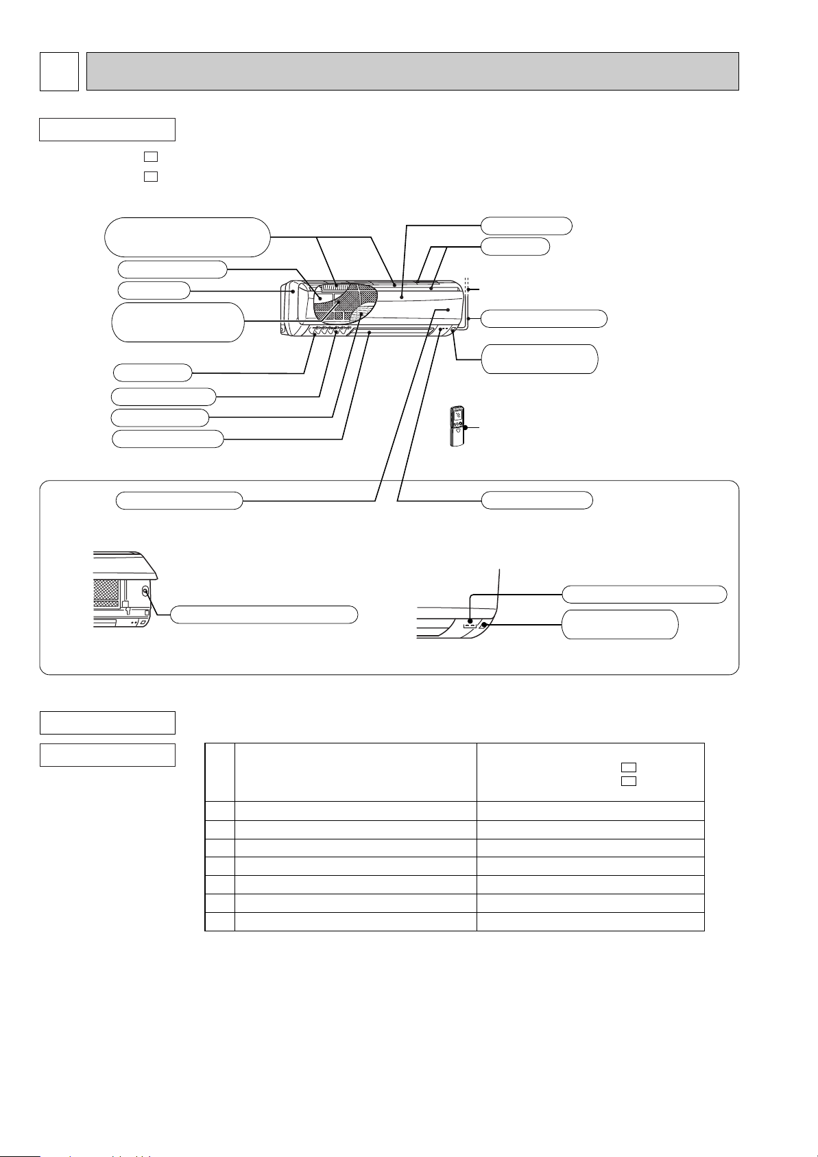
PART NAMES AND FUNCTIONS
INDOOR UNIT
MSZ-A09YV MSZ-A12YV -
Air cleaning filter
(white bellows type)
Heat exchanger
Catechin air filter
(With deodorizer)
Air outlet
Vertical vanes
Line flow fan
Horizontal vane
Operation section
(When the front panel is opened)
E1
E1
Panel
Front panel
Air inlet
to Breaker
Power supply cord
Remote control
receiving section
Remote controller
Display section
ACCESSORIES
INDOOR UNIT
Emergency operation switch
Operation indicator lamp
Remote control
receiving section
2
ON/OFF
TOO
COOL
PM
AM
TOO
WARM
ON/OFF
FAN
TOO
WARM
TOO
COOL
VANE
MODE
ECONO COOL
STOP
START
HR.
MIN.
AMPM
CLOCK
˚C
AM
RESET CLOCK
I FEEL
COOL
DRY
AUTO
HEAT
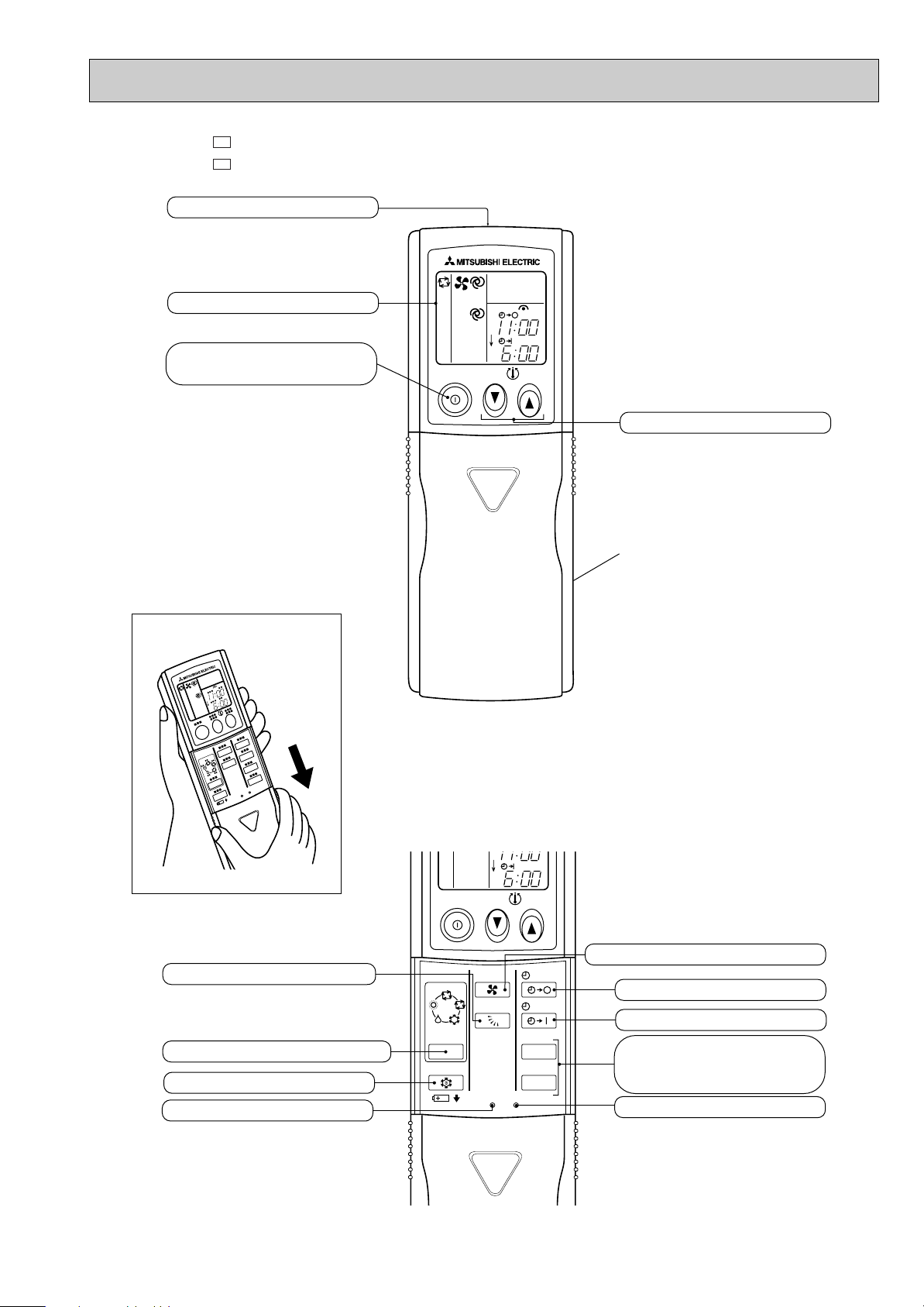
Open the front lid.
Signal transmitting section
Operation display section
OPERATE /STOP
(ON /OFF) button
TEMPERATURE buttons
OPERATION SELECT button
FAN SPEED CONTROL button
OFF-TIMER button
HR. button
MIN. button
(TIME SET button)
ON-TIMER button
RESET button
ECONO COOL button
VANE CONTROL button
CLOCK SET button
Indication of remote controller model
MSZ-A09YV MSZ-A12YV -
E1
E1
3
1.5+ 440V
250V 3.15A
93:5A 250V
MSBPC20 12V 250"
ERZV10D471
S201DH1Y
5P
JM1aN-ZTMP-DC12V
136:i3: 2A
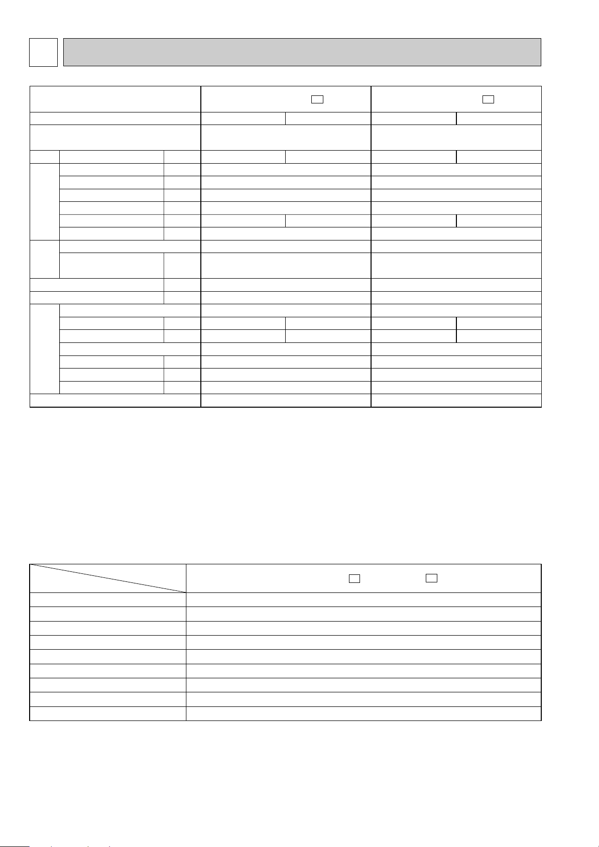
INDOOR UNIT
Item
Model
Indoor fan capacitor
Fuse
Thermal fuse
Vane motor
Varistor
Solid state relay
Terminal block
Contactor
Indoor fan motor thermal fuse
MSZ-A09YV -
E1
MSZ-A12YV -
E1
(C11)
(F11)
(F12)
(MV)
(NR11)
(SR141)
(TB)
(52C)
2
MSZ-A09YV -
E1
MSZ-A12YV -
E1
Indoor model
Function
Power supply
Single phase
230V,50Hz
10
0.17
35
—
0.17
RC4V19-LA
WHT-BLK 413
BLK-RED 334
815O278O244
9
5
3
10
10
10
KG04A
Cooling
504/360
W
/222
W
88
37/29W/21
W
1,010/770W/540
W
Heating
564/402
W
/246
W
94
38/30W/21
W
1,110/840W/580
W
Single phase
230V,50Hz
10
0.19
40
—
0.19
RC4V19-KA
WHT-BLK 316
BLK-RED 299
815O278O244
10
5
3
10
10
10
KG04A
Cooling
630/462
W
/288
W
95
39/31W/22
W
1,030/800W/570
W
Heating
642/474W/312
W
94
38/30
W
/22
W
1,050/820W/600
W
Air flow
(High/Med.W/LowW)
Power outlet
Running current ✽1
Power input Rated frequency
Auxiliary heater
Power factor ✽1
Fan motor current ✽1
Model
Winding
resistance(at20:)
Dimensions WOHOD
Weight
Air direction
Sound level
(High/Med.W/LowW)
Fan speed(High/Med.W/LowW)
Fan speed regulator
Thermistor RT11(at25:)
Thermistor RT12(at25:)
Thermistor RT13(at25:)
Remote controller model
K /h
A
A
W
A(kW)
%
A
"
mm
kg
dB(A)
rpm
k"
k"
k"
Electrical
data
Fan
motor
Special
remarks
Capacity
SPECIFICATION
NOTE : Test conditions are based on ISO 5151
Cooling : Indoor DB27: WB19:
Outdoor DB35: WB 24:
Heating : Indoor DB 20: WB15:
Outdoor DB 7: WB 6:
Refrigerant piping length (one way): 5m
w Reference value
✽1 Measured under rated operating frequency.
Specifications and rating conditions of main electric parts
4

3
90
80
70
60
50
40
30
20
10
63 125 250 500 1000 2000 4000 8000
NC-60
NC-50
NC-40
NC-30
NC-20
NC-70
OCTAVE BAND SOUND PRESSURE LEVEL, dB re 0.0002 MICRO BAR
BAND CENTER FREQUENCIES, Hz
Test conditions,
Cooling : Dry-bulb temperature 27: Wet-bulb temperature 19:
APPROXIMATE
THRESHOLD OF
HEARING FOR
CONTINUOUS
NOISE
COOLING
FUNCTION
37
38
SPL(dB(A))
LINE
High
FAN SPEED
HEATING
Heating : Dry-bulb temperature 20: Wet-bulb temperature 15:
NOISE CRITERIA CURVES
MSZ-A09YV -
E1
MSZ-A12YV -
Test conditions,
Cooling : Dry-bulb temperature 27: Wet-bulb temperature 19:
Heating : Dry-bulb temperature 20: Wet-bulb temperature 15:
90
80
70
60
50
40
30
E1
FAN SPEED
High
FUNCTION
COOLING
HEATING
SPL(dB(A))
39
38
LINE
NC-70
NC-60
NC-50
NC-40
NC-30
APPROXIMATE
20
THRESHOLD OF
HEARING FOR
CONTINUOUS
OCTAVE BAND SOUND PRESSURE LEVEL, dB re 0.0002 MICRO BAR
NOISE
10
63 125 250 500 1000 2000 4000 8000
BAND CENTER FREQUENCIES, Hz
INDOORUNIT
WALL
1m
0.8m
MICROPHONE
NC-20
5

4
OUTLINES AND DIMENSIONS
MSZ-A09YV -
INDOOR UNIT
278
60
58
162
Wireless remote controller
E1
81.5
606
783
815
149
19
Power supply cord
Lead to right 1.0m
Lead to left 0.3m
Installation
plate
Indoor unit
81.5
41
30
Air out
242 5
Air in
7 or more
244
326326
Installation plate
Liquid line
Gas line
{
Insulation
90
110
Drain hose
(Connected part O,D)
Insulation
Unit : mm
133.5
231.5
42
2.5
81.5
Wall hole
[6.35-0.5m
[9.52-0.43m
[37 O.D
[21 I.D
[16
[28
4.5
271
[65
MSZ-A12YV -
INDOOR UNIT
278
60
58
162
Wireless remote controller
E1
783
815
606
19
Installation
plate
Indoor
unit
41
149
Power supply cord
Lead to right 1.0m
Lead to left 0.3m
30
Air out
242
Air in
7 or more
244
326326
5
Installation plate
Liquid line
Gas line
{
Insulation
90
110
Drain hose
(Connected part O,D)
Insulation
Unit : mm
161.5161.5
218.5
42
2.5
81.581.5
Wall hole [65
[6.35-0.5m
[9.52-0.43m
[37 O.D
[21 I.D
[16
[28
17.5
258
6

5
SYMBOL
C11
F11
F12
MF
MV
SYMBOL
NR11
RT11
RT12
RT13
SR141
SYMBOL
SR142
T11
TB
52C
NAME
INDOOR FAN CAPACITOR
FUSE (3.15A)
THERMAL FUSE (93:)
INDOOR FAN MOTOR (INNER FUSE)
VANE MOTOR
NAME
VARISTOR
ROOM TEMPERATURE THERMIST OR
INDOOR COIL THERMISTOR (MAIN)
INDOOR COIL THERMISTOR (SUB)
SOLID STATE RELAY
NAME
SOLID STATE RELAY
TRANSFORMER
TERMINAL BLOCK
CONTACTOR
GRN/YLW
BLK
GRY
YLW
BRN
WHT
RED
MF
1
2
3
4
5
6
3
SR141 SR142
5
3
1
C11
RT13
RT12
CN
112
CN
111
CN
121
151
CN
109CN125
CN
1R1
CN
MV
52
32
5
RT11
CN211
NR11
ELECTRONIC CONTROL P.C. BOARD
F11
T11
230V~
BRN
TB
L
3
N
2
RED
WHT
BLU
F12
BLU
BLU
1
2
BLU
1
2
3
CN201
3
4
52C
12V
TO OUTDOOR
UNIT
CONNECTING
L
3
N
2
12V
TO OUTDOOR
FOR MXZ type
UNIT
CONNECTING
REMOTE
CONTROLLER
POWER MONITOR
RECEIVER
SAFETY
DEVICE (FAN)
P.C. BOARD
LD103
GRN
CIRCUIT BREAKER
POWER
SUPPLY
CORD
~/N 230V
50Hz
PE
WIRING DIAGRAM
MSZ-A09YV MSZ-A12YV -
INDOOR UNIT
E1
E1
MODELS WIRING DIAGRAM
NOTE:1. About the outdoor side electric wiring refer to the outdoor unit electric wiring diagram for servicing.
2. Use copper conductors only. (For field wiring)
3. Symbols below indicate.
/: Terminal block, : Connector
6
MSZ-A09YV -
INDOOR UNIT
REFRIGERANT SYSTEM DIAGRAM
E1
Refrigerant pipe [9.52
(with heat insulator)
MSZ-A12YV -
INDOOR UNIT
Indoor coil
Indoor
heat
exchanger
Room temperature
thermistor
RT11
Refrigerant flow in cooling
Refrigerant flow in heating
thermistor
RT12(main)
Indoor coil
thermistor
RT13(sub)
Flared connection
Flared connection
Refrigerant pipe
[6.35
(with heat insulator)
Indoor
heat
exchanger
Room temperature
thermistor
RT11
7
Indoor coil
thermistor
RT13(sub)
E1
Refrigerant pipe [9.52
(with heat insulator)
Indoor coil
thermistor
RT12(main)
Flared connection
Flared connection
Refrigerant pipe
[6.35
(with heat insulator)
Unit:mm

7
SERVICE FUNCTIONS
MSZ-A09YV MSZ-A12YV -
E1
E1
7-1. TIMER SHORT MODE
For service, set time can be shortened by short circuit of JPG and JPS the electronic control P.C. board.
The time will be shortened as follows. (Refer to page 18.)
Set time : 1-minute ➔ 1-second
Set time : 3-minute ➔ 3-second (It takes 3 minutes for the compressor to start operation. However, the starting time is
shortened by short circuit of JPG and JPS.)
7-2. P.C. BOARD MODIFICATION FOR INDIVIDUAL OPERATION
A maximum of 4 indoor units with wireless remote controllers can be used in a room.
In this case, to operate each indoor unit individually by each remote controller, P.C. boards of remote controller must be
modified according to the number of the indoor unit.
How to modify the remote controller P.C. board
Remove batteries before modification.
The board has a print as shown below :
Remote controller model : KG04A
J2
NOTE : For remodelling, take out
the batteries and press the
OPERATE/STOP(ON/OFF)
button twice or 3 times at
first.
After finish remodelling,
put back the batteries then
press the RESET button.
J1
The P.C. board has the print “J1” and “J2”. Solder “J1” and “J2” according to the number of indoor unit as shown in Table
1.
After modification, press the RESET button.
Table 1
1 unit operation
No. 1 unit
No. 2 unit
No. 3 unit
No. 4 unit
How to set the remote controller exclusively for particular indoor unit.
After you turn the breaker ON, the first remote controller that sends the signal to the indoor unit will be regarded as the remote
controller for the indoor unit.
The indoor unit will only accepts the signal from the remote controller that has been assigned to the indoor unit once they are
set.
The setting will be cancelled if the breaker has turned off, or the power supply has shut down.
Please conduct the above setting once again after the power has restored.
No modification
–
–
–
2 units operation
Same as at left
Solder J1
–
–
3 units operation
Same as at left
Same as at left
Solder J2
–
4 units operation
Same as at left
Same as at left
Same as at left
Solder both J1 and J2
7-3. AUTO RESTART FUNCTION
When the indoor unit is controlled with the remote controller, the operation mode, the set temperature, and the fan speed
are memorized by the indoor electronic control P.C. board. The “AUTO RESTART FUNCTION” sets to work the moment
power has restored after power failure. Then, the unit will restart automatically.
However if the unit is operated in “I FEEL CONTROL” mode before power failure,
the operation is not memorized. In “I FEEL CONTROL” mode, the operation is decided by the initial room temperature.
8
 Loading...