

Page 1

mitsubishi :: Mitsubishi Truck Montero SR 4WD
V6-3.5L SOHC (1997)
Page 2

> Relays and Modules > Relays and Modules - Accessories and Optional Equipment > Antenna Control Module > Component Information > Technical Service Bulletins > Power Antenna - Motor Inspection Procedure Revisions
Antenna Control Module: Technical Service BulletinsPower Antenna - Motor Inspection Procedure Revisions
NO.: TSB-97-54-002Date: January, 1997Model: 1992-97 Montero
Subject:CORRECTED MOTOR ANTENNA ANDCONTROL UNIT INSPECTION PROCEDURES- SERVICE MANUAL REVISION
[TSB Revision TSB-97-54-002]
PURPOSEThis bulletin corrects motor antenna and motor antenna control unit inspection procedures. These corrected procedures involve plug, pin, and terminalconfiguration and numbering.
Write the TSB revision number of this bulletin in the "TSB Revision" box at the bottom of the affected service manual page.
AFFECTED VEHICLES1992-97 Montero
AFFECTED MANUALS1992-95 Montero Service Manual, Volume 2, Page 54-1441996 Montero Service Manual, Volume 2, Page 54-1151997 Montero Service Manual, Volume 2, Page 54-78
SERVICE MANUAL REVISIONS
Page 3

> Relays and Modules > Relays and Modules - Accessories and Optional Equipment > Antenna Control Module > Component Information > Technical Service Bulletins >
Power Antenna - Motor Inspection Procedure Revisions > Page 8
Montero SR 4WD V6-3.5L SOHC (1997)
Page 4

1992-95 Montero Service Manual, Volume 2, Page 54-144Delete the marked-through information from the manual as shown and replace it with the new procedures.
Page 5

> Relays and Modules > Relays and Modules - Accessories and Optional Equipment > Antenna Control Module > Component Information > Technical Service Bulletins >
Power Antenna - Motor Inspection Procedure Revisions > Page 9
Montero SR 4WD V6-3.5L SOHC (1997)
Page 6

1992-95 Montero Service Manual, Volume 2, Page 54-144Add the new inspection procedures to the top of page 54-144 in place of the procedures deleted previously.
Page 7

> Relays and Modules > Relays and Modules - Accessories and Optional Equipment > Antenna Control Module > Component Information > Technical Service Bulletins >
Power Antenna - Motor Inspection Procedure Revisions > Page 10
Montero SR 4WD V6-3.5L SOHC (1997)
Page 8
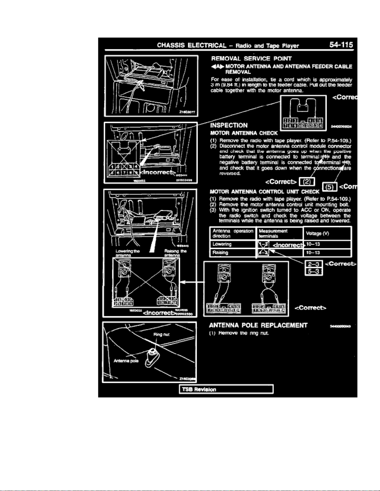
1996 Montero Service Manual, Volume 2, Page 54-115Correct the motor antenna and control unit inspection procedures as shown.
Page 9

> Relays and Modules > Relays and Modules - Accessories and Optional Equipment > Antenna Control Module > Component Information > Technical Service Bulletins >
Power Antenna - Motor Inspection Procedure Revisions > Page 11
Montero SR 4WD V6-3.5L SOHC (1997)
Page 10

1997 Montero Service Manual, Volume 2, Page 54-78Correct the motor antenna and control unit inspection procedures as shown.
Page 11

Page 12

> Relays and Modules > Relays and Modules - Accessories and Optional Equipment > Keyless Entry Module > Component Information > Locations
Keyless Entry Module: Locations
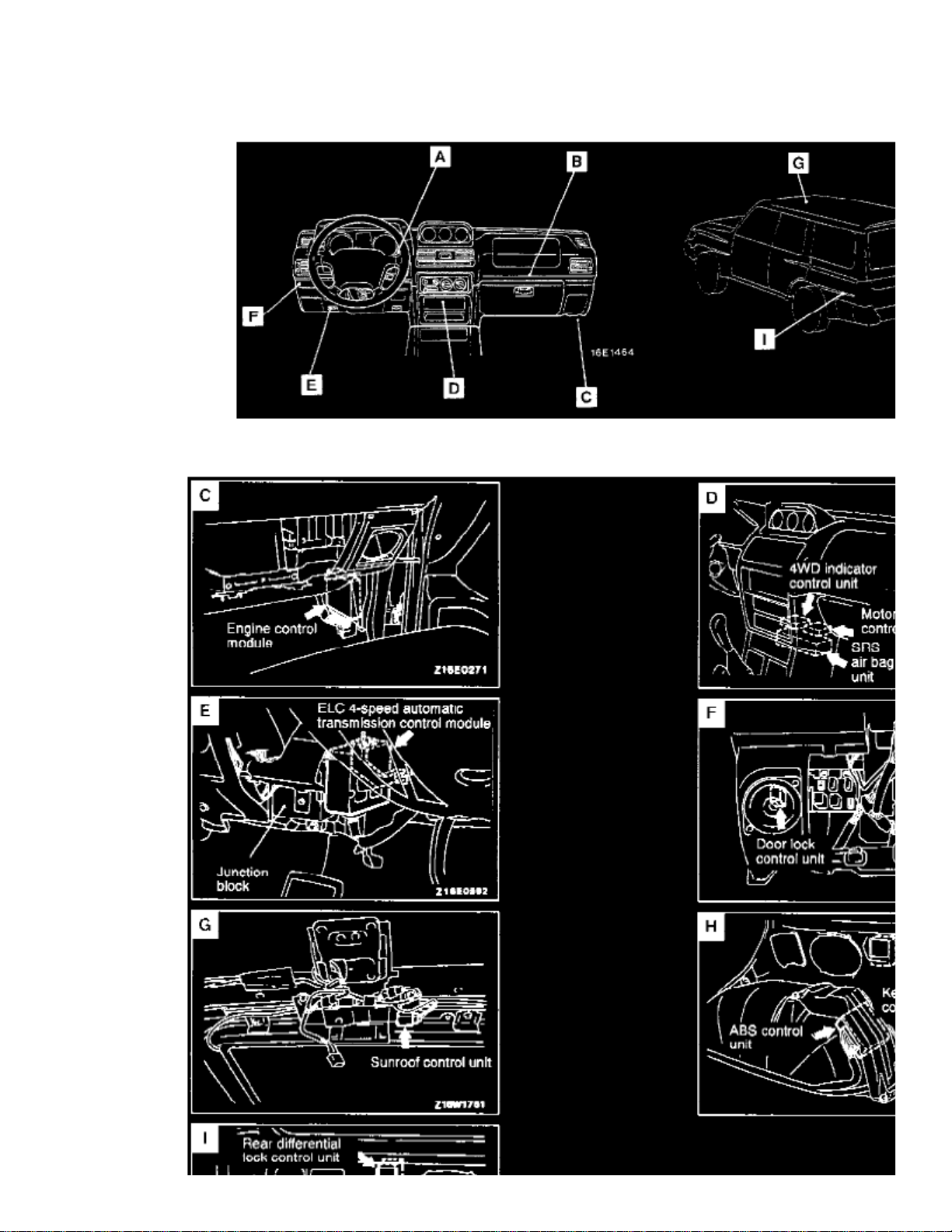
Control Unit Location Overall View
Page 13

> Relays and Modules > Relays and Modules - Accessories and Optional Equipment > Keyless Entry Module > Component Information > Locations > Page 15
Montero SR 4WD V6-3.5L SOHC (1997)
Control Unit Location Views C - I
Page 14

CONTROL UNIT VIEW
Keyless Entry Control Unit H
Page 15

Page 16

> Relays and Modules > Relays and Modules - Body and Frame > Door Lock Relay > Component Information > Locations
Door Lock Relay: Locations
Relay Location Overviews
Page 17

> Relays and Modules > Relays and Modules - Body and Frame > Door Lock Relay > Component Information > Locations > Page 20
Montero SR 4WD V6-3.5L SOHC (1997)
Page 18

Page 19

Relay Location Views A - J
RELAY VIEW
Door Lock Relay I
Page 20

> Relays and Modules > Relays and Modules - Body and Frame > Keyless Entry Module > Component Information > Locations
Keyless Entry Module: Locations
Control Unit Location Overall View
Page 21

> Relays and Modules > Relays and Modules - Body and Frame > Keyless Entry Module > Component Information > Locations > Page 24
Montero SR 4WD V6-3.5L SOHC (1997)
Control Unit Location Views C - I
Page 22

CONTROL UNIT VIEW
Keyless Entry Control Unit H
Page 23

Page 24

> Relays and Modules > Relays and Modules - Body and Frame > Power Door Lock Control Module > Component Information > Locations
Power Door Lock Control Module: Locations
Control Unit Location Overall View
Page 25

> Relays and Modules > Relays and Modules - Body and Frame > Power Door Lock Control Module > Component Information > Locations > Page 28
Montero SR 4WD V6-3.5L SOHC (1997)
Control Unit Location Views C - I
Page 26

CONTROL UNIT VIEW
Door Lock Control Unit F
Page 27

Page 28

> Relays and Modules > Relays and Modules - Body and Frame > Power Seat Relay > Component Information > Locations
Power Seat Relay: Locations
Relay Location Overviews
Relay Location View K
RELAY VIEW
Power Seat Relay Box K
Page 29

Page 30
> Relays and Modules > Relays and Modules - Body and Frame > Sunroof / Moonroof Module > Component Information > Locations
Sunroof / Moonroof Module: Locations
Control Unit Location Overall View
Page 31

> Relays and Modules > Relays and Modules - Body and Frame > Sunroof / Moonroof Module > Component Information > Locations > Page 35
Montero SR 4WD V6-3.5L SOHC (1997)
Control Unit Location Views C - I
Page 32

CONTROL UNIT VIEW
Sunroof Control Unit G
Page 33

Page 34

> Relays and Modules > Relays and Modules - Brakes and Traction Control > ABS Main Relay > Component Information > Testing and Inspection
ABS Main Relay: Testing and Inspection
ABS RELAY BOX (WITH BUILT-IN MOTOR RELAY AND VALVE RELAY)
1. Disconnect the ABS relay box connector.2. Check the continuity between the terminals of the ABS relay (box-side) connector when current is flowing.3. Repeat Step 2 when current is not flowing.4. Refer to the illustration for terminal layout and specifications.
Page 35

Page 36

> Relays and Modules > Relays and Modules - Brakes and Traction Control > Brake Fluid Pump Relay > Component Information > Locations
Brake Fluid Pump Relay: Locations
Relay Location Overviews
Page 37

> Relays and Modules > Relays and Modules - Brakes and Traction Control > Brake Fluid Pump Relay > Component Information > Locations > Page 43
Montero SR 4WD V6-3.5L SOHC (1997)
Page 38

Page 39

Relay Location Views A - J
RELAY VIEW
ABS Relay Box (with built-in A
motor relay and valve relay)
Page 40

> Relays and Modules > Relays and Modules - Brakes and Traction Control > Brake Fluid Solenoid Valve Relay > Component Information > Locations
Brake Fluid Solenoid Valve Relay: Locations
Relay Location Overviews
Page 41

> Relays and Modules > Relays and Modules - Brakes and Traction Control > Brake Fluid Solenoid Valve Relay > Component Information > Locations > Page 47
Montero SR 4WD V6-3.5L SOHC (1997)
Page 42

Page 43

Relay Location Views A - J
RELAY VIEW
ABS Relay Box (with built-in A
motor relay and valve relay)
Page 44

> Relays and Modules > Relays and Modules - Brakes and Traction Control > Electronic Brake Control Module > Component Information > Specifications
Electronic Brake Control Module: Specifications
TIGHTENING SPECIFICATIONS
Bracket "A" Mounting Bolts ................................................................................................................................................................. 12 Nm (9 ft. lbs.)
Page 45

Page 46

> Relays and Modules > Relays and Modules - Brakes and Traction Control > Electronic Brake Control Module > Component Information > Specifications > Page 51
Electronic Brake Control Module: Locations
Control Unit Location Overall View
Page 47

> Relays and Modules > Relays and Modules - Brakes and Traction Control > Electronic Brake Control Module > Component Information > Specifications > Page 52
Montero SR 4WD V6-3.5L SOHC (1997)
Control Unit Location Views C - I
Page 48

CONTROL UNIT VIEW
ABS Control Unit H
Page 49

Page 50

> Relays and Modules > Relays and Modules - Brakes and Traction Control > Electronic Brake Control Module > Component Information > Testing and Inspection > Terminal Resistance & Continuity Check
Electronic Brake Control Module: Testing and InspectionTerminal Resistance & Continuity Check
(Part 1 Of 2)
(Part 2 Of 2)
1. Turn the ignition switch "OFF" and disconnect the ABS-ECU connector before measuring resistance and checking continuity.2. Measure resistance and check continuity between the terminals indicated in the tables.3. The terminal layouts are shown in the illustrations.
Page 51

Page 52

> Relays and Modules > Relays and Modules - Brakes and Traction Control > Electronic Brake Control Module > Component Information > Testing and Inspection > Terminal Resistance & Continuity Check > Page 55
Electronic Brake Control Module: Testing and InspectionTerminal Voltage Check
Page 53

> Relays and Modules > Relays and Modules - Brakes and Traction Control > Electronic Brake Control Module > Component Information > Testing and Inspection >
Terminal Resistance & Continuity Check > Page 56
Montero SR 4WD V6-3.5L SOHC (1997)
(Part 1 Of 2)
Page 54

(Part 2 Of 2)
- Measure the voltages between terminal Nos. 12, 25 and 42 (ground terminals) and each respective terminal.
- The terminal layouts are shown in the illustrations.
Page 55

Page 56

> Relays and Modules > Relays and Modules - Brakes and Traction Control > Electronic Brake Control Module > Component Information > Testing and Inspection > Page 57
Electronic Brake Control Module: Service and Repair
1. Remove the third rear seat from above the rear wheel wells, if necessary.2. Remove the quarter trim.3. Refer to the illustration, and remove bracket "A."4. Remove the bracket and the electronic control unit. 5. Reverse procedure to install.
Page 57

Page 58

> Relays and Modules > Relays and Modules - Cruise Control > Cruise Control Module > Component Information > Locations
Cruise Control Module: Locations
Control Unit Location Overall View
Control Unit Location Views A - B
CONTROL UNIT VIEW
Cruise Control Unit A
Page 59

Page 60

> Relays and Modules > Relays and Modules - HVAC > Blower Motor Relay > Component Information > Locations
Blower Motor Relay: Locations
Relay Location Overviews
Page 61

> Relays and Modules > Relays and Modules - HVAC > Blower Motor Relay > Component Information > Locations > Page 66
Montero SR 4WD V6-3.5L SOHC (1997)
Page 62

Page 63

Relay Location Views A - J
RELAY VIEW
Blower Motor Relay G
Page 64

> Relays and Modules > Relays and Modules - HVAC > Blower Motor Relay > Component Information > Locations > Page 67
Blower Motor Relay: Testing and Inspection
1. Remove the heater relay from the junction box.2. Use an ohmmeter to check for continuity between the terminals.
Page 65

Page 66

> Relays and Modules > Relays and Modules - HVAC > Compressor Clutch Relay > Component Information > Locations
Compressor Clutch Relay: Locations
Relay Location Overviews
Page 67

> Relays and Modules > Relays and Modules - HVAC > Compressor Clutch Relay > Component Information > Locations > Page 71
Montero SR 4WD V6-3.5L SOHC (1997)
Page 68

Page 69

Relay Location Views A - J
RELAY VIEW
A/C Compressor Relay B
Page 70

> Relays and Modules > Relays and Modules - HVAC > Condenser Fan Motor Relay, HVAC > Component Information > Locations
Condenser Fan Motor Relay: Locations
Relay Location Overviews
Page 71

> Relays and Modules > Relays and Modules - HVAC > Condenser Fan Motor Relay, HVAC > Component Information > Locations > Page 75
Montero SR 4WD V6-3.5L SOHC (1997)
Page 72

Page 73

Relay Location Views A - J
RELAY VIEW
Condenser Fan Motor Relay B
Page 74

> Relays and Modules > Relays and Modules - HVAC > Condenser Fan Motor Relay, HVAC > Component Information > Locations > Page 76
Condenser Fan Motor Relay: Testing and Inspection
1. Remove the condenser fan motor relay and compressor relay from the relay box at the left of the engine compartment.2. Use an ohmmeter to check for continuity between the terminals.
Page 75

Page 76

> Relays and Modules > Relays and Modules - HVAC > Control Module HVAC > Component Information > Locations
Control Module HVAC: Locations
Control Unit Location Overall View
Control Unit Location Views A - B
CONTROL UNIT VIEW
A/C Control Unit B
Page 77

Page 78

> Relays and Modules > Relays and Modules - Lighting and Horns > Headlamp Relay > Component Information > Locations
Headlamp Relay: Locations
Relay Location Overviews
Page 79

> Relays and Modules > Relays and Modules - Lighting and Horns > Headlamp Relay > Component Information > Locations > Page 84
Montero SR 4WD V6-3.5L SOHC (1997)
Page 80

Page 81

Relay Location Views A - J
RELAY VIEW
Headlight Relay B
Page 82

> Relays and Modules > Relays and Modules - Lighting and Horns > Headlamp Relay > Component Information > Locations > Page 85
Headlamp Relay: Testing and Inspection
Headlight Relay And Tail Light Relay Check
Headlight And Taillight Relay Table
1. Remove the headlight relay or tail light relay from the relay box in the engine compartment.2. Apply battery positive voltage to terminal (2), and check for continuity between the terminals when terminal (4) is grounded.
Page 83

Page 84

> Relays and Modules > Relays and Modules - Lighting and Horns > Horn Relay > Component Information > Locations
Horn Relay: Locations
Relay Location Overviews
Page 85

> Relays and Modules > Relays and Modules - Lighting and Horns > Horn Relay > Component Information > Locations > Page 89
Montero SR 4WD V6-3.5L SOHC (1997)
Page 86

Page 87

Relay Location Views A - J
RELAY VIEW
Horn Relay C
Page 88

> Relays and Modules > Relays and Modules - Lighting and Horns > Horn Relay > Component Information > Locations > Page 90
Horn Relay: Testing and Inspection
Horn Relay
Horn Relay - Check
1. Remove the horn relay from the engine compartment.2. Apply battery positive voltage to terminal (2), and check for continuity between the terminals when terminal (4) is grounded.
Page 89

Page 90

> Relays and Modules > Relays and Modules - Lighting and Horns > Interior Lighting Module > Component Information > Specifications
Interior Lighting Module: Specifications
Cigarette light illumination light ........................................................................................................................................................................... 1.4 (74) W
: The values in parentheses denote SAE grade numbers.NOTE
Page 91

Page 92

> Relays and Modules > Relays and Modules - Lighting and Horns > Tail Lamp Relay > Component Information > Locations
Tail Lamp Relay: Locations
Relay Location Overviews
Page 93

> Relays and Modules > Relays and Modules - Lighting and Horns > Tail Lamp Relay > Component Information > Locations > Page 97
Montero SR 4WD V6-3.5L SOHC (1997)
Page 94

Page 95

Relay Location Views A - J
RELAY VIEW
Taillight Relay B
Page 96

> Relays and Modules > Relays and Modules - Lighting and Horns > Tail Lamp Relay > Component Information > Locations > Page 98
Tail Lamp Relay: Testing and Inspection
Headlight Relay And Tail Light Relay Check
Headlight And Taillight Relay Table
1. Remove the headlight relay or tail light relay from the relay box in the engine compartment.2. Apply battery positive voltage to terminal (2), and check for continuity between the terminals when terminal (4) is grounded.
Page 97

Page 98

> Relays and Modules > Relays and Modules - Power and Ground Distribution > Relay Box > Component Information > Locations > Component Locations
Relay Box: Component Locations
Page 99

> Relays and Modules > Relays and Modules - Power and Ground Distribution > Relay Box > Component Information > Locations > Component Locations > Page 104
Montero SR 4WD V6-3.5L SOHC (1997)
Page 100

Centralized Relay
 Loading...