

Mitsubishi Electric MCF-13NV-WH, MUCF-13NV-E3, MCF-13NV-E3WH Service Manual
SERVICE MANUAL
FLOOR AND CEILING TYPE AIR CONDITIONERS
CONTENTS
1. TECHNICAL CHANGES ····································2
2. PART NAMES AND FUNCTIONS······················2
3. SPECIFICATION·················································4
4. NOISE CRITERIA CURVES ······························ 5
5. OUTLINES AND DIMENSIONS·························6
6. WIRING DIAGRAM ············································7
7. REFRIGERANT SYSTEM DIAGRAM················8
8. PERFORMANCE CURVES································9
9. MICROPROCESSOR CONTROL ····················15
10. SERVICE FUNCTIONS·····································21
11. TROUBLESHOOTING······································22
12. DISASSEMBLY INSTRUCTIONS·····················28
13. PARTS LIST······················································32
14. OPTIONAL PARTS ···········································35
Wireless type
Model
MCF-13NV-
(WH)
·MUCF-13NV-
E3E3
(When installed on the ceiling)
(When installed on the floor)
No. OB239
MCF-13NV -
E3

2
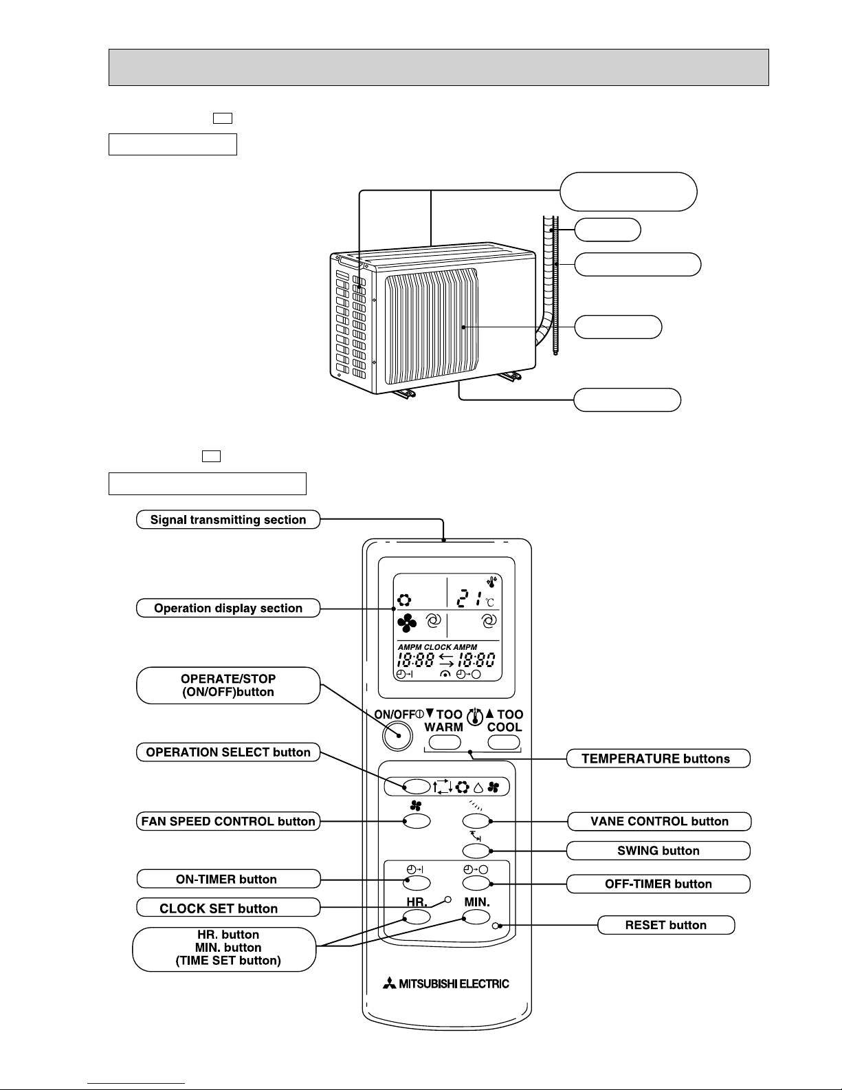
PART NAMES AND FUNCTIONS
INDOOR UNIT
(When installed on the floor)
(When the air inlet grille is opened.)
Deodorizing filter (gray sponge type)(option)
Air filter
Remote controller
Air inlet
Operation section
Air cleaning filter (whilte bellows type)(option)
Front panel
Receiving section
Operation indicator lamp
Horizontal vane
Vertical vanes
Emergency operation switch
(When installed on the ceiling)
2
TECHNICAL CHANGES
1
MCF-13NV - ➔MCF-13NV -
1. Indoor unit model name has changed.
MUCF-13NV - ➔MUCF-13NV -
1. Outdoor unit model has changed.
E3E2
E3E2
MCF-13NV -
E3
3
RESETRESET
CLOCKCLOCK
MCF-13NV -
E3
OUTDOOR UNIT
MUCF-13NV -
E3
Air inlet
Piping
Drain hose
Air outlet
Drain outlet
(back and side)
REMOTE CONTROLLER
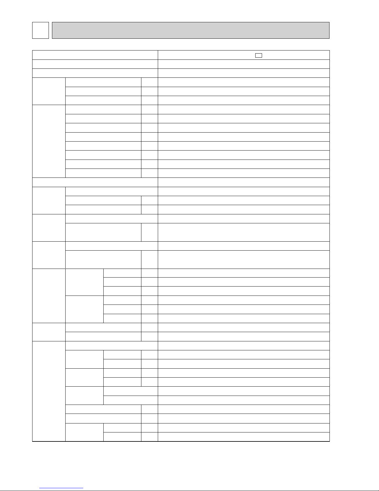
SPECIFICATION
4
3
Model
Function
Power supply
Capacity
Dehumidification
Air flow
Power outlet
Running current
Power input
Auxiliary heater
Power factor
Starting current
Compressor motor current
Fan motor current
kW
R/h
K/h
A
A
W
A(kW)
%
A
A
A
W
"
"
"
mm
mm
mm
mm
mm
mm
kg
kg
dB
dB
rpm
rpm
kg
cc
k"
k"
Capacity
Electrical
data
Coefficient of performance(C.O.P)
Compressor
Indoor
fan motor
Outdoor
fan motor
Dimensions
Indoor unit
Indoor unit
Width
Height
Depth
Width
Height
Depth
Indoor unit
Outdoor unit
Indoor unit
Outdoor unit
Indoor unit
Outdoor unit
RT11(at 25:)
RT12(at 25:)
Sound level
(Hi)
Fan speed
(Hi)
Fan speed
regulator
Outdoor unit
Outdoor unit
Air direction
Refrigerant filling capacity(R-22)
Refrigerating machine oil <Model>
Thermistor
Weight
Special
remarks
Model
Output
Winding resistance (at 20:)
Model
Winding resistance (at 20:)
Model
Winding resistance (at 20:)
MCF-13NV-
E3
Cooling
Single phase, 220-240V, 50Hz
3.7
1.6
678
10
6.3-6.3
1,310-1,380
—
95-91
35-38
5.74-5.72
0.56-0.58
2.82-2.68
RH-231VHAT
1,100
C-R2.11 C-S3.97
RA6V33-CB
WHT-BLK 176
BLK-RED 413
34
5
43-44
49
1,080-1,130
700-750
3
1
0.85
520 <MS-56>
10
10
1,100
650
180
780
540
255
26
RB4V19-AB
WHT-BLK 203.2 BLK-YLW 45.9
YLW-BLU 32.7 BLU-BRN 44.4
BRN-RED 23.3
NOTE:Test conditions
Cooling : Indoor DB27°C WB19°C Outdoor DB35°C WB24°C

5
NOISE CRITERIA CURVES
4
90
80
70
60
50
40
30
20
10
63 125 250 500 1000 2000 4000 8000
NC-60
NC-50
NC-40
NC-30
NC-20
NC-70
OCTAVE BAND SOUND PRESSURE LEVEL, dB re 0.002 MICRO BAR
BAND CENTER FREQUENCIES, Hz
Test conditions,
Cooling : DB 27
:
WB 19
:
APPROXIMATE
THRESHOLD OF
HEARING FOR
CONTINUOUS
NOISE
Hi
(220-240V)
NOTCH
43-44
SPL(dB
(A)) LINE
MCF-13NV -
E3
MUCF-13NV -
E3
90
80
70
60
50
40
30
20
10
63 125 250 500 1000 2000 4000 8000
NC-60
NC-50
NC-40
NC-30
NC-20
NC-70
OCTAVE BAND SOUND PRESSURE LEVEL, dB re 0.002 MICRO BAR
BAND CENTER FREQUENCIES, Hz
Test conditions,
Cooling : DB 35
:
WB 24
:
APPROXIMATE
THRESHOLD OF
HEARING FOR
CONTINUOUS
NOISE
Hi
NOTCH
49
SPL(dB
(A)) LINE
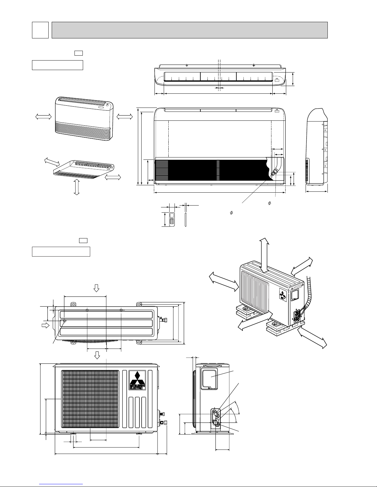
OUTLINES AND DIMENSIONS
6
5
(When installed on the floor)
(When installed on the ceiling)
50cm or more
50cm or more
50cm or more
50cm or more
100cm or more
650
616.5
80.8 906 112.8
114
16
1100
93
77
113
143
180
17042.5
160
56
17.5
12.7
Gas line
6.35
Liquid line
INDOOR UNIT
MCF-13NV -
E3
MUCF-13NV -
E3
320
25
43-
35-
155
90
104
74
260
10
780
500
122
40
540
320
285
255
Service panel
Gas refrigerant
pipe joint
Refrigerant pipe
(flared)[12.7
Liquid refrigerant
pipe joint
Refrigerant pipe
(flared) [6.35
Airout
Air in
Air in
109
32
110
147
Drainage
3holes [33
Unit: mm
OUTDOOR UNIT
If clearance
behind the outdoor
units only 40
B or 50
B
side
A must be
fully open.
10cm or more
10cm or more
10cm or more
Outdoor
unit
35cm or more
REQUIRED SPACE
A
40cm or more
7
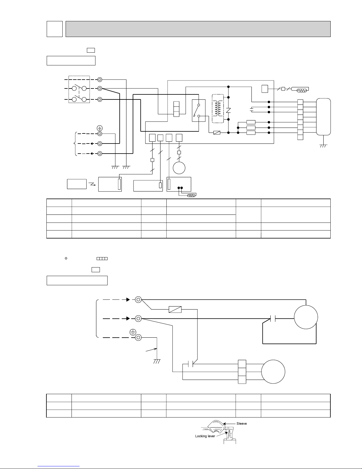
WIRING DIAGRAM6
INDOOR UNIT
AUTO RESTART
ASSEMBLY
5
CN
104
SR144
SR142
SR143
LDFM
LDFL
LDFH
BLK
BLU
YLW
6
4
BLK
BLU
YLW
5
TB
CIRCUIT BREAKER
SW/THERMO
4
1
2
W
3
4
W
F11
52C
NR11
P.C.BOARD
RT11
CN201
3
151
CN
6
6
MV
HIC1
TRANS
101CN113
CN
BLU
REMOTE
CONTROLLER
DISPLAY &
RECEIVER
P.C.BOARD
5
5
GRN/YLW
W
WHT
W
BLU
N
2
W
BRN
N
W
L
GRN/YLW
TO OUTDOOR
UNIT
CONNECTING
POWER SUPPLY
~/N 220-240V
50Hz
MF
ORN
RED
7
3
2
1
RT12
2
2
WHT
RED
ORN
WHT
GRN/YLW
8
BRN
112
CN
C11
ELECTRONIC CONTROL P.C BOARD
LDC12
LDC11
LDCOM
220-240v~
SYMBOL
SR142~
SR144
TB
52C
SYMBOL
MV
NR11
RT11
RT12
SYMBOL
C11
F11
HIC1
MF
NAME
NAME NAME
INDOOR FAN CAPACITOR
FUSE (3.15A)
DC/DC CONVERTER
INDOOR FAN MOTOR(INNER FUSE)
VANE MOTOR
VARISTOR
ROOM TEMPERATURE THERMISTOR
COIL TEMPERATURE THERMISTOR
SOLID STATE RELAY
TERMINAL BLOCK
CONTACTOR
PE
MODEL WIRING DIAGRAM
MCF-13NV -
E3
1Slide the sleeve.
2Pull the wire while pushing the locking lever.
NOTE : 1. Use copper conductors only (For field wiring).
2. “W” shows the terminals with a lock mechanism,
so they cannot be removed when you pull the lead wire.
Be sure to pull the lead wire by pushing the locking lever
(projected part) of the terminal with a finger.
OUTDOOR UNIT
MODEL WIRING DIAGRAM
SYMBOL
MF
TB
SYMBOL
F
MC
SYMBOL
C1
C2
NAME
NAME NAME
COMPRESSOR CAPACITOR
OUTDOOR FAN CAPACITOR
FUSE(2A)
COMPRESSOR(INNER THERMOSTAT)
OUTDOOR FAN MOTOR(INNER THERMOSTAT)
TERMINAL BLOCK
W
W
MF
BLK
WHT
RED
N
2
220-240V~
BLU
BLU
WHT
BLK
RED
C1
TB
F
C2
RED
WHT
1
2
3
GRN/YLW
FROM
INDOOR UNIT
CONNECTING
C
S
R
MC
WHT
WHT
MUCF-13NV -
E3
NOTE:1. For the outdoor electric wiring refer to the outdoor unit electric wiring diagram for servicing.
2. Use copper conductors only.(For field wiring)
3. Symbols below indicate.
: Terminal block, : Connector
8
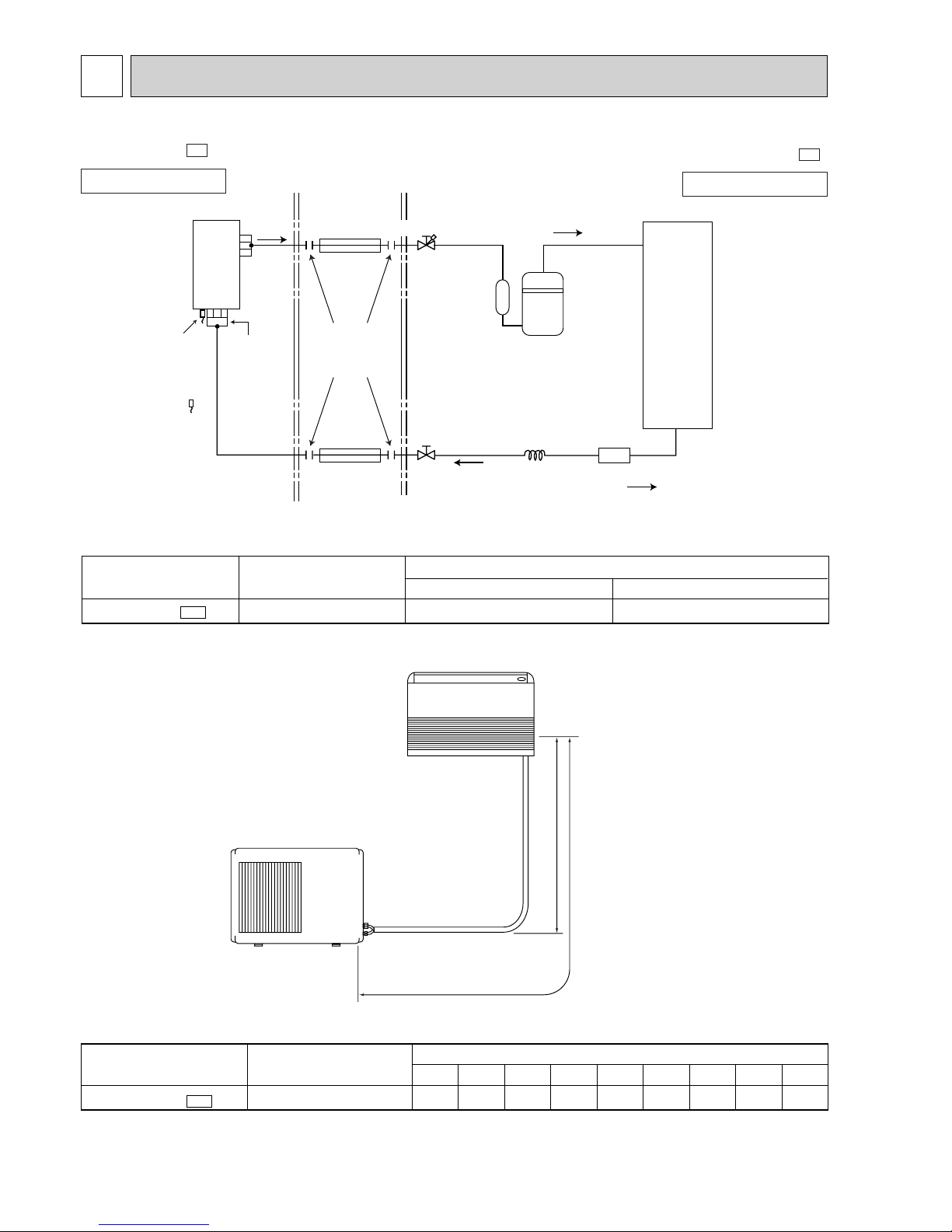
REFRIGERANT SYSTEM DIAGRAM7
Refrigerant flow in cooling
Indoor
heat
exchanger
Indoor coil
thermistor
RT12
Room
temperature
thermistor
RT11
(option)
(With heat insulation)
Refrigerant pipe
[
12.7
(option)
(With heat insulation)
Refrigerant pipe
[
6.35
Flared
connection
Stop valve
(with service port)
Stop valve
Compressor
Strainer
Capillary tube
[3.0 ✕[1.6 ✕ 300
Outdoor
heat
exchanger
Distributor
INDOOR UNIT
OUTDOOR UNIT
Unit:mm
MCF-13NV -
E3
MUCF-13NV -
E3
A: Refrigerant piping
Max.length
15m(49ft)
✽
Max. Height difference
5m(16ft)
✽Height difference should be within
5m regardless of which unit,
indoor or outdoor position is high.
MAX. REFRIGERANT PIPING LENGTH & MAX. HEIGHT DIFFERENCE
ADDITIONAL REFRIGERANT CHARGE (R-22 : g)
Length : m (ft)
A
15(49)
Gas
[12.7(1/2)
Liquid
[6.35(1/4)
Piping size O.D : mm(in.)
Model
MCF-13NV - E3
Outdoor unit precharged
850
15m
120
8m
15
10m
45
MCF-13NV - E3
Calculation : Xg=15g/mx(A-7)m
Model
Refrigerant piping length (one way)
14m
105
13m
90
11m6012m
75
9m
30
7m
0
MAX. HEIGHT DIFFERENCE
9
PERFORMANCE CURVES
8
The standard data contained in these specifications apply only to the operation of the air conditioner under normal conditions,
Since operating conditions vary according to the areas where these units are installed. The following information has been
provided to clarify the operating characteristics of the air conditioner under the conditions indicated by the performance curve.
(1) GUARANTEED VOLTAGE
Rated voltage : ±10% (198~264V), 50Hz
(2) AIR FLOW
Air flow should be set at MAX.
(3) MAIN READINGS
(1) Indoor intake air wet-bulb temperature : ˚CWB
(2) Indoor outlet air wet-bulb temperature : ˚CWB
(3) Outdoor intake air dry-bulb temperature : ˚CDB
(4) Total input : W
Indoor air wet-bulb temperature difference on the left side of the chart on this page shows the difference between the
indoor intake air wet-bulb temperature and the indoor outlet air wet-bulb temperature for your reference at service.
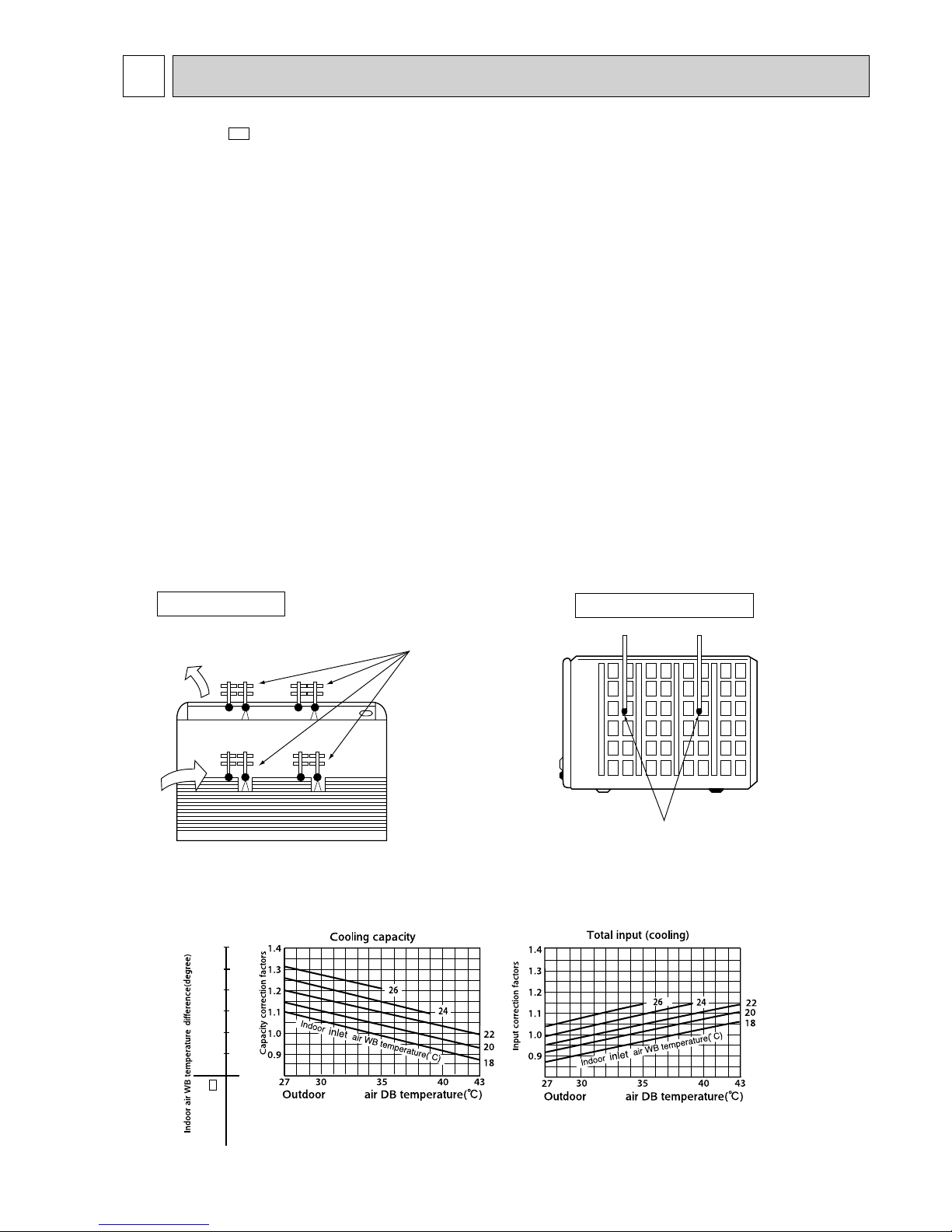
How to measure the indoor air wet-bulb temperature difference
1. Attach at least 2 sets of wet-and dry-bulb thermometers to the indoor air intake as shown in the figure, and at least 2 sets of
wet-and-dry-bulb thermometers to the indoor air outlet. The thermometers must be attached to the position where air speed
is high.
2. Attach at least 2 sets of dry-bulb thermometers to the outdoor air intake.
Cover the thermometers to prevent direct rays of the sun.
3. Check that the air filter is cleaned.
4. Open windows and doors of the room.
5. Press the EMERGENCY OPERATION switch to start the EMERGENCY COOL MODE.
6. When system stabilizes after more than 15 minutes, measure temperature and take an average temperature.
7. 10 minutes later, measure temperature again and check that the temperature does not change.
Air in
Air out
Wet-and dry-bulb
thermometers
FRONT VIEW
Dry-bulb
thermometers
BACK VIEW
INDOOR UNIT
OUTDOOR UNIT
10.4
9.5
8.7
7.8
7.0
6.2
MCF-13NV-
E3
intake
intake
MCF-13NV -
E3
10
Dry Bulb temperature (˚C)
20
25
30
Relative humidity (%)
50
60
70
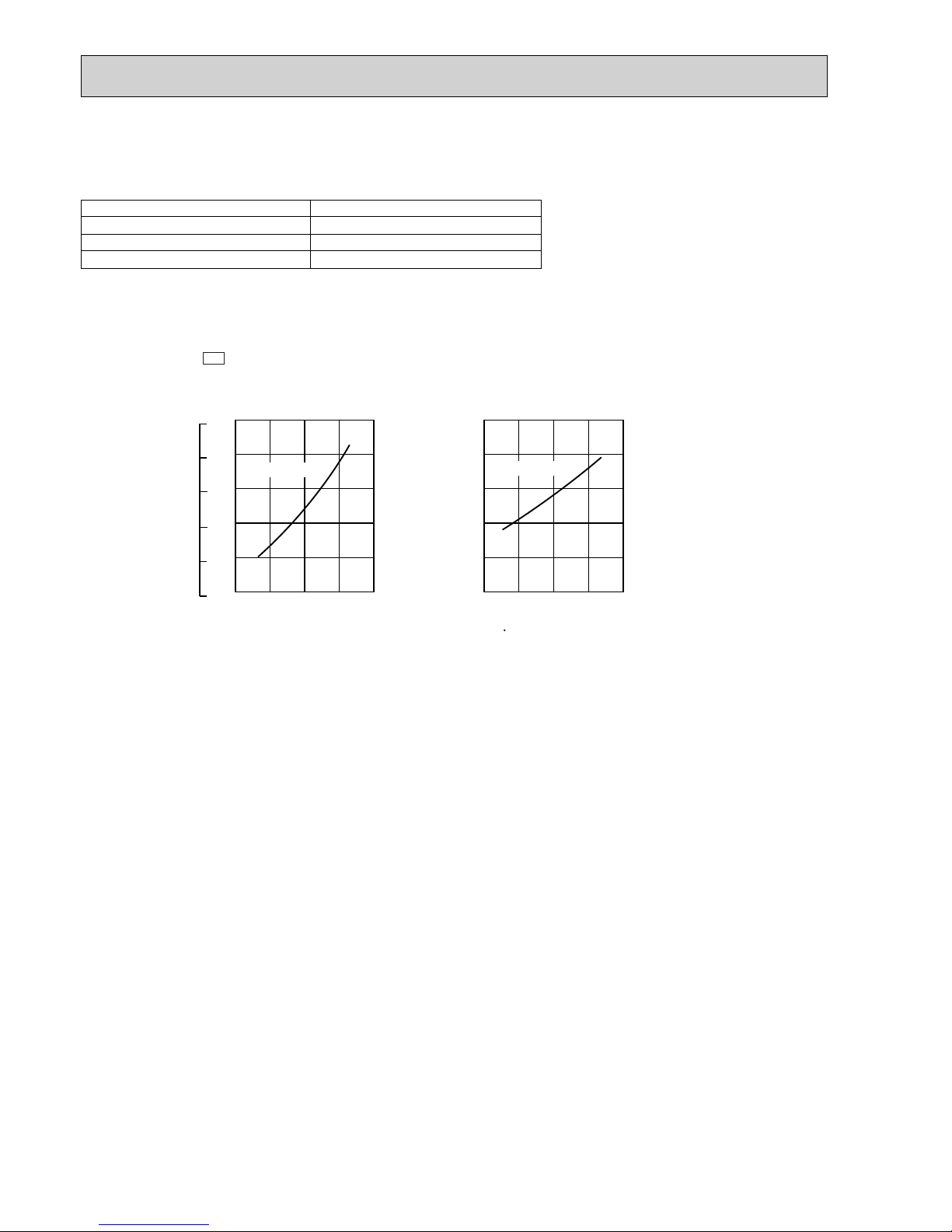
OUTDOOR LOW PRESSURE AND OUTDOOR UNIT CURRENT
COOL operation
1 Both indoor and outdoor units are under the same temperature/humidity condition
2 Air flow should be set at MAX.
20 25 30
0.3
0.4
0.5
0.6
0.7
0.8
20 25 30
3
4
5
6
7
8
Ambient temperature (:)
Ambient humidity(%)
18
50 60 70
32
(:)
(%)
Ambient temperature (:)
Ambient humidity(%)
18
50 60 70
32
(%)
Outdoor unit current (A)
Outdoor low pressure
7
6
5
4
3
8
(kgf/F•G)(MPa•G)
(:)
220-240V
220-240V
3 The unit of pressure has been changed to MPa on the international system of units(SI unit system).
The conversion factor is : 1(MPa • G) =10.2(kgf/
ff
• G)
MUCF-13NV -
E3
11
OUTDOOR DB(:)
INDOOR INDOOR
21 25 27 30
DB(:) WB(:)
Q SHC SHF INPUT Q SHC SHF INPUT Q SHC SHF INPUT Q SHC SHF INPUT
21 18 4.35 2.26 0.52 1048 4.16 2.16 0.52 1100 4.00 2.08 0.52 1153 3.85 2.00 0.52 1205
21 20 4.53 1.81 0.40 1100 4.35 1.74 0.40 1166 4.22 1.69 0.40 1192 4.07 1.63 0.40 1245
22 18 4.35 2.43 0.56 1048 4.16 2.33 0.56 1100 4.00 2.24 0.56 1153 3.85 2.15 0.56 1205
22 20 4.53 1.99 0.44 1100 4.35 1.91 0.44 1166 4.22 1.86 0.44 1192 4.07 1.79 0.44 1245
22 22 4.72 1.51 0.32 1140 4.55 1.46 0.32 1212 4.44 1.42 0.32 1245 4.26 1.36 0.32 1297
23 18 4.35 2.61 0.60 1048 4.16 2.50 0.60 1100 4.00 2.40 0.60 1153 3.85 2.31 0.60 1205
23 20 4.53 2.18 0.48 1100 4.35 2.09 0.48 1166 4.22 2.02 0.48 1192 4.07 1.95 0.48 1245
23 22 4.72 1.70 0.36 1140 4.55 1.64 0.36 1212 4.44 1.60 0.36 1245 4.26 1.53 0.36 1297
24 18 4.35 2.78 0.64 1048 4.16 2.66 0.64 1100 4.00 2.56 0.64 1153 3.85 2.46 0.64 1205
24 20 4.53 2.36 0.52 1100 4.35 2.26 0.52 1166 4.22 2.19 0.52 1192 4.07 2.12 0.52 1245
24 22 4.72 1.89 0.40 1140 4.55 1.82 0.40 1212 4.44 1.78 0.40 1245 4.26 1.70 0.40 1297
24 24 4.96 1.39 0.28 1192 4.77 1.34 0.28 1258 4.66 1.31 0.28 1297 4.51 1.26 0.28 1362
25 18 4.35 2.96 0.68 1048 4.16 2.83 0.68 1100 4.00 2.72 0.68 1153 3.85 2.62 0.68 1205
25 20 4.53 2.54 0.56 1100 4.35 2.43 0.56 1166 4.22 2.36 0.56 1192 4.07 2.28 0.56 1245
25 22 4.72 2.08 0.44 1140 4.55 2.00 0.44 1212 4.44 1.95 0.44 1245 4.26 1.87 0.44 1297
25 24 4.96 1.59 0.32 1192 4.77 1.53 0.32 1258 4.66 1.49 0.32 1297 4.51 1.44 0.32 1362
26 18 4.35 3.13 0.72 1048 4.16 3.00 0.72 1100 4.00 2.88 0.72 1153 3.85 2.77 0.72 1205
26 20 4.53 2.72 0.60 1100 4.35 2.61 0.60 1166 4.22 2.53 0.60 1192 4.07 2.44 0.60 1245
26 22 4.72 2.26 0.48 1140 4.55 2.18 0.48 1212 4.44 2.13 0.48 1245 4.26 2.04 0.48 1297
26 24 4.96 1.78 0.36 1192 4.77 1.72 0.36 1258 4.66 1.68 0.36 1297 4.51 1.63 0.36 1362
26 26 5.11 1.23 0.24 1258 4.96 1.19 0.24 1323 4.88 1.17 0.24 1362 4.74 1.14 0.24 1402
27 18 4.35 3.30 0.76 1048 4.16 3.16 0.76 1100 4.00 3.04 0.76 1153 3.85 2.92 0.76 1205
27 20 4.53 2.90 0.64 1100 4.35 2.78 0.64 1166 4.22 2.70 0.64 1192 4.07 2.60 0.64 1245
27 22 4.72 2.45 0.52 1140 4.55 2.37 0.52 1212 4.44 2.31 0.52 1245 4.26 2.21 0.52 1297
27 24 4.96 1.98 0.40 1192 4.77 1.91 0.40 1258 4.66 1.86 0.40 1297 4.51 1.81 0.40 1362
27 26 5.11 1.43 0.28 1258 4.96 1.39 0.28 1323 4.88 1.37 0.28 1362 4.74 1.33 0.28 1402
28 18 4.35 3.48 0.80 1048 4.16 3.33 0.80 1100 4.00 3.20 0.80 1153 3.85 3.08 0.80 1205
28 20 4.53 3.08 0.68 1100 4.35 2.96 0.68 1166 4.22 2.87 0.68 1192 4.07 2.77 0.68 1245
28 22 4.72 2.64 0.56 1140 4.55 2.55 0.56 1212 4.44 2.49 0.56 1245 4.26 2.38 0.56 1297
28 24 4.96 2.18 0.44 1192 4.77 2.10 0.44 1258 4.66 2.05 0.44 1297 4.51 1.99 0.44 1362
28 26 5.11 1.63 0.32 1258 4.96 1.59 0.32 1323 4.88 1.56 0.32 1362 4.74 1.52 0.32 1402
29 18 4.35 3.65 0.84 1048 4.16 3.50 0.84 1100 4.00 3.36 0.84 1153 3.85 3.23 0.84 1205
29 20 4.53 3.26 0.72 1100 4.35 3.13 0.72 1166 4.22 3.04 0.72 1192 4.07 2.93 0.72 1245
29 22 4.72 2.83 0.60 1140 4.55 2.73 0.60 1212 4.44 2.66 0.60 1245 4.26 2.55 0.60 1297
29 24 4.96 2.38 0.48 1192 4.77 2.29 0.48 1258 4.66 2.24 0.48 1297 4.51 2.17 0.48 1362
29 26 5.11 1.84 0.36 1258 4.96 1.78 0.36 1323 4.88 1.76 0.36 1362 4.74 1.70 0.36 1402
30 18 4.35 3.83 0.88 1048 4.16 3.66 0.88 1100 4.00 3.52 0.88 1153 3.85 3.39 0.88 1205
30 20 4.53 3.44 0.76 1100 4.35 3.30 0.76 1166 4.22 3.21 0.76 1192 4.07 3.09 0.76 1245
30 22 4.72 3.02 0.64 1140 4.55 2.91 0.64 1212 4.44 2.84 0.64 1245 4.26 2.72 0.64 1297
30 24 4.96 2.58 0.52 1192 4.77 2.48 0.52 1258 4.66 2.42 0.52 1297 4.51 2.35 0.52 1362
30 26 5.11 2.04 0.40 1258 4.96 1.98 0.40 1323 4.88 1.95 0.40 1362 4.74 1.89 0.40 1402
31 18 4.35 4.00 0.92 1048 4.16 3.83 0.92 1100 4.00 3.68 0.92 1153 3.85 3.54 0.92 1205
31 20 4.53 3.63 0.80 1100 4.35 3.48 0.80 1166 4.22 3.37 0.80 1192 4.07 3.26 0.80 1245
31 22 4.72 3.21 0.68 1140 4.55 3.09 0.68 1212 4.44 3.02 0.68 1245 4.26 2.89 0.68 1297
31 24 4.96 2.78 0.56 1192 4.77 2.67 0.56 1258 4.66 2.61 0.56 1297 4.51 2.53 0.56 1362
31 26 5.11 2.25 0.44 1258 4.96 2.18 0.44 1323 4.88 2.15 0.44 1362 4.74 2.08 0.44 1402
32 18 4.35 4.17 0.96 1048 4.16 4.00 0.96 1100 4.00 3.84 0.96 1153 3.85 3.69 0.96 1205
32 20 4.53 3.81 0.84 1100 4.35 3.65 0.84 1166 4.22 3.54 0.84 1192 4.07 3.42 0.84 1245
32 22 4.72 3.40 0.72 1140 4.55 3.28 0.72 1212 4.44 3.20 0.72 1245 4.26 3.06 0.72 1297
32 24 4.96 2.97 0.60 1192 4.77 2.86 0.60 1258 4.66 2.80 0.60 1297 4.51 2.71 0.60 1362
32 26 5.11 2.45 0.48 1258 4.96 2.38 0.48 1323 4.88 2.34 0.48 1362 4.74 2.27 0.48 1402
CAPACITY: 3.7 kW INPUT : 1310 W SHF : 0.70
PERFORMANCE DATA
COOL operation(220V)
MCF-13NV - : MUCF-13NV -
E3E3
NOTE Q : Total capacity (kW) SHF : Sensible heat factor
SHC : Sensible heat capacity (kW) INPUT : Total power input (W)
 Loading...