

Page 1
RACK MOUNT COMPUTERS
(Manual Part Number MAN-RCKPC-001)
Page 2
Manual P/N MAN-RCKPC-001
Designed, and Manufactured specifically for Mitsubishi Electric Automation, Inc., by AVG
Mitsubishi Electric Automation, Inc. (MEAU)
500 Corporate Woods Parkway, Vernon Hills, IL 60061
Phone: (847) 478-2100 • Fax: (847) 478-2253 • www.meauic.com
AVG Automation
Mitsubishi Approved IC Service Center
4140 Utica Ridge Rd. • Bettendorf, IA 52722-1327
Phone: 1-563-359-7501 • Fax: 1-563-359-9094 • www.avg.net
WARNING!
Programmable control devices such as Rack Computers must not be used as stand-alone protection in any
application. Unless proper safeguards are used, unwanted start-ups could result in equipment damage or
personal injury. The operator must be made aware of this hazard and appropriate precautions must be taken.
In addition, consideration must be given to the use of an emergency stop function that is independent of the
programmable controller.
The diagrams and examples in this user manual are included for illustrative purposes only. The manufacturer
cannot assume responsibility or liability for actual use based on the diagrams and examples.
This publication may contain references to products produced and/or offered by other companies. The
product and company names may be trademarked and are the sole property of their respective owners.
MEAU and/or AVG Automation disclaims any proprietary interest in the marks and names of others.
Trademarks
© Copyright 2003, AVG Automation
All Rights Reserved
No part of this manual shall be copied, reproduced, or transmitted in any way without the prior written
consent of AVG Automation. AVG Automation retains the exclusive rights to all information included in this
document.
Page 3

CONTENTS
Warning/Copyright....................................................................... inside cover
Contents ........................................................................................................ i
CHAPTER 1 INTRODUCTION
Manual Organization............................................................................. 1
Introduction ........................................................................................... 2
What you need to get started ............................................................... 3
Technical Support ................................................................................. 3
CHAPTER 2 MODELS AND EQUIPMENT
Model Number/Description ................................................................... 5
Accessories and Optional Software ..................................................... 6
CHAPTER 3 SPECIFICATIONS
Computer Specifications....................................................................... 8
Mechanical Specifications .................................................................... 8
CHAPTER 4 INSTALLATION
Installing the MC100 Rack Mount Computer — Overview .................. 9
Mounting ............................................................................................. 10
Outline Dimensions .......................................................................... 10
CHAPTER 5 EXTERNAL COMPONENTS
Front Panel Components.................................................................... 12
Rear Panel COmponents ................................................................... 14
CHAPTER 6 COMMUNICATIONS SETUP
Setup ................................................................................................... 16
CHAPTER 7 MAINTENANCE AND UPGRADES
Upgrades............................................................................................. 17
Expansion Card Installation............................................................. 17
Maintenance ....................................................................................... 19
Preserving Data ............................................................................... 19
Cleaning System Components ........................................................ 19
Error/Improvement Report ..................................................................... 21
MAN-RCKPC-001 MC100 Series Rack Mount Computer
i
Page 4

CONTENTS
This page intentionally left blank.
ii
MC100 Series Rack Mount Computer MAN-RCKPC-001
Page 5
INTRODUCTION 1
Manual Organization
The table, below provides an overall description of the topics covered within this manual.
Chapters
Introduction
1
2
3
4
5
6
Models and
Equipment
Specifications
Installation
External
Components
Communication
Setup
Provides Manual Organization, what is provided with
the unit. Introduction to the Industrial Rack Mount
Computer. Discusses how to get help with questions or
problems you might encounter.
Provides you with key features of the Rack Mount
Computer. Lists the optional equipment available.
Specifications provide detailed information. Included
are connector and expansion card information, CPU
type; service power requirements; operating and
storage temperatures; available memory; serial
communications specs; dimensions, weight, etc.
Shows the dimensions for the Rack Mount Computer.
Provides location and description of the available
connectors and expansion card slots.
Instructions on how to set up the Rack Mount Computer
communications.
Maintenance and
7
MAN-RCKPC-001 MC100 Series Rack Mount Computer
Upgrades
Provides instructions on expansion card installation and
explains basic maintenance.
1
Page 6

1 INTRODUCTION
Introduction
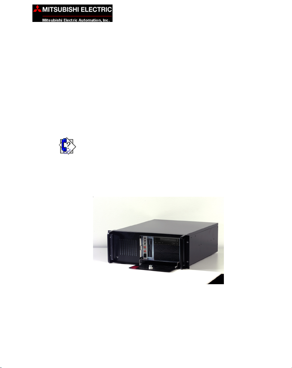
The Mitsubishi Electric Automation MC100 Rack Mount Computer is a nondisplay type package that can easily run visual, maintenance, information, and
control software. Packaging this computer with one of our vibrant LCD displays produces a workstation with the power to direct machine processes, collect critical data, and communicate with the front office for high level production interaction.
The MC100 is a full-featured computer able to withstand harsh environments.
It has the advantage of rugged design, high performance, and easy access for
upgrade or maintenance. MC100 Series Computers are intended for applications requiring the highest reliability, as with all Mitsubishi electronic components.
The MC100 Series computer features a 850 Mhz Intel Pentium III processor
single board computer, with standard models providing the necessary computing power for any of today’s most popular applications, with optional capability
of the high power computing processors. It is housed in a rugged 4U industry
standard size steel enclosure.
Operating systems are included as part of every package. Optional operating
systems and application software can be installed upon request, providing an
“Out of the Box” solution for your custom application. The computers are CE,
UL/CUL & FCC Class I compliant, and are rated to operate from 0 to 50 ºC, at
a noncondensing humidity of 10–95%.
This manual will take you through the steps necessary to get your Standard
19-inch Industrial Rack Computer installed and running in the shortest possible time. This manual covers Model MC100.
Following are some of the Industrial Rack Mount Computer standard design
features:
• Computer system board is run by an Intel Pentium III microprocessor.
• Windows XP Pro (installed) operating system.
• CD ROM 48x type (minimum)
• 2 Serial Ports, 1 dedicated RS-232 and 1 RS-232/422/485 selectable
• 2 USB ports
• XVGA output (60 feet maximum)
• 1.44 MB floppy disk drive
• PS/2 mouse connector
• PS/2 Keyboard connector
• Each unit provides 6 slots for expansion cards
— 3 PCI — 2 ISA — 1 PICMG
• 40 Gb hard disk drive
• Rack Mount - 4U Industry Standard size steel enclosure
2
MC100 Series Rack Mount Computer MAN-RCKPC-001
Page 7
What you need to get started:
Hardware
• Industrial Rack Mount 19-inch Computer, Model MC100
Software
• Windows XP Pro (installed)
Technical Support
If you are having difficulty with a particular aspect of installation or setup, technical support is available at 1-800-950-7781 (Auto Attendant, Option 4) or
visit our website at www.meauic.com.
INTRODUCTION 1
MAN-RCKPC-001 MC100 Series Rack Mount Computer
3
Page 8

1 INTRODUCTION
This page intentionally left blank.
4
MC100 Series Rack Mount Computer MAN-RCKPC-001
Page 9

Model Number/Description
MC100 19" 4U Industrial Rack Mount Computer
MODELS AND EQUIPMENT 2
MAN-RCKPC-001 MC100 Series Rack Mount Computer
5
Page 10

2 MODELS AND EQUIPMENT
Accessories and Optional Software
There are replacement parts and other optional equipment available to customize or upgrade the Rack Mount Computer to fit your application. The following tables provide you with a list of this equipment.
Product Part Number
32MB Disk on Chip Flash Memory MC600
64MB Disk on Chip Flash Memory MC601
128MB Disk on Chip Flash Memory MC602
256MB Disk on Chip Flash Memory MC603
40GB HDD MC610
256MB MEM MC615
512MB MEM MC616
Standard Keyboard MC620
Keyboard with Trackball MC621
Multimedia I/R board MC622
19" R/M Industrial Membrane Keyboard MC623
2 Button Mouse MC624
Modem, PCI, 56K V.90 MC630
2-way Video Splitter/Repeater MC635
Shielded Video Cable - 6' MC640
Shielded Video Cable - 10' MC641
Shielded Video Cable - 30' MC644
Shielded Video Cable - 60' MC646
RS-232 Serial Cable - 6' MC651
RS-232 Serial Cable - 10' MC652
RS-232 Serial Cable - 30' MC655
RS-232 Serial Cable - 60' MC656
Accessories
6
MC100 Series Rack Mount Computer MAN-RCKPC-001
Page 11

2 MODELS AND EQUIPMENT
Optional Software
Product Part Number
Windows NT 4.0 Workstation MC701
Windows 2000 Server MC702
Windows 2000 Pro MC703
Windows XP Pro MC704
MS DOS MC706
LINUX Server MC707
LINUX W/S MC708
Windows NT/e (Embedded) MC710
Windows XP/e (Embedded) MC711
Windows CE 3.0 (Embedded) MC712
VX Works MC713
Microsoft Access MC750
Microsoft Office MC751
Microsoft Excel MC752
Procomm MC760
PC Anywhere MC761
Norton Anti-Virus MC762
MacAfee Anti-Virus MC763
MAN-RCKPC-001 MC100 Series Rack Mount Computer
7
Page 12

3 SPECIFICATIONS
COMPUTER SPECIFICATIONS:
CPU Type: Intel Pentium III (850 Mhz minimum)
Memory: 256 MB (Expandable up to 512 MB)
BIOS: Flash ROM
Main Drive: 40 Gb Hard Disk Drive
SSD: (Optional SDD Disk on Chip – 64 MB Minimum, Expandable to 256 MB)
Serial Ports: 1 dedicated RS-232 port, 1 RS-232/RS-422/RS-485 port
Parallel Port: SPP/EPP/ECP supported, Configurable to LPT1
LAN: 10 Base-T/100 Base-TX Ethernet
USB: 2 ports (1.1 compliant))
PS/2 Interface: One PS/2 Mouse port on front of unit and one PS/2 Mouse port on rear of
VGA Output: XVGA Output (60 ft. maximum)
Floppy Drive: 1.44 MB
CD ROM: 48x type (minimum)
Operating System: Windows XP Pro OS (Standard)
Watchdog Timer: 12 level timer with timeout intervals from 0.5 –30000 seconds
unit (you can only use one port at a time)and one PS/2 Keyboard Port (rear)
MECHANICAL SPECIFICATIONS:
Housing Material: Rack Mount 4U heavy duty steel — MEAU Black
Connectors: Serial Ports: Two D-Sub 9-pin (male)
Dimensions: 18.986" W x 6.929" H x 21.0" D (482.244 x 175.997 x 533.40 mm)
Weight: 17.0 kg
Expansion Slots: 6 Open Slots for expansion cards — 3 PCI, 2 ISA, 1 PICMG;
Power Supply: ATX 250 Watts, AC 115/230 VAC 50-60 Hz
Cooling Fan: Supported, washable air filter
Environmental: Operating Temperature: 0 to 50 °C (32 to 122 °F)
8
Parallel Port: One D-Sub 25-pin (female)
Keyboard and Mouse Ports: Two PS/2 (rear) and One PS/2 (front)
One RJ-45 for Ethernet; One D-Sub 15-pin (female) forVideo; Two USB
Humidity: 10 to 95% non-condensing
Agency Approvals: CE Mark, UL/CUL, FCC compliant
MC100 Series Rack Mount Computer MAN-RCKPC-001
Page 13

4 INSTALLATION
INSTALLING THE MC100 RACK MOUNT COMPUTER — OVERVIEW
Installing the Rack Mount Computer requires the following three major
steps:
The MC100 Rack Mount Computer is a rack mount unit with handles for easy
Mount the Unit
Make
Connections
removal and portability. Mounting of the unit requires drilling 4 holes in the
mounting surface for the mounting studs. Please see the Mounting chapter
beginning on page 10 for mounting diagrams and instructions.
Now that your Rack Mount Computer is installed, you are ready to connect
your unit to the power source and peripheral devices. The Rack Mount
Computer’s Serial Ports support one RS-232 and one RS-232/RS-422/RS485 connector. The Parallel Port supports SPP/EPP/ECP. There are two USB
Ports (1.1), and one Video Port that supports up to XVGA Resolution. Note
that the Rack Mount Computer can be powered by 115 VAC or 230 VAC. See
the section on External Components, beginning on page 12 for further information. To install an expansion card, see the Upgrades and Maintenance chapter beginning on page 18.
Communications
Setup
MAN-RCKPC-001 MC100 Series Rack Mount Computer
Once you have the Rack Mount Computer installed, and a monitor and any
peripheral devices you require for your application connected, you are ready
to power up the computer and establish communications. Refer to page 16.
9
Page 14

4 INSTALLATION
Mounting
The Rack Mount Computer is mounted on a rack. The following diagrams show the outline and
cutout dimensions necessary to mount the panel using the studs.
19-inch Industrial Rack Mount Computer —
Model MC100 — Outline Dimensions
10
MC100 Series Rack Mount Computer MAN-RCKPC-001
Page 15

4 INSTALLATION
19-inch Industrial Rack Mount Computer —
Model MC100 — Outline Dimensions
MAN-RCKPC-001 MC100 Series Rack Mount Computer
11
Page 16

5 EXTERNAL COMPONENTS
FRONT Panel Components
HDD ACTIVE LED
POWER LED
MOUSE PORT
AIR FILTER TAB
POWER CONTROL
SWITCH
RESET
BUTTON
FLOPPY
DISK DRIVE
CDROM
DRIVE
To access the front panel components, unlock and open the panel door. Located on the front of the Rack Computer are the following components.
HDD Active Indicator
Labeled HDD1, the first green LED indicator will illuminate when the Hard
disk drive is being accessed (is active). (HDD2 is not used)
Power LED
Next to the Power Control push button is a green LED indicator. It will illuminate when the computer is on.
Mouse Port
PS/2-compatible mouse port. (There is also a mouse port on the rear panel,
but you can only use one port at time.)
Air Filter Tab
The system fan air filter can easily be removed, washed to remove contaminants, and then replaced. Simply pull the air filter retainer by the white plastic
tab (shown above) and slide filter out.
Power Control Switch
Use the Power Control switch to turn on the computer.
12
MC100 Series Rack Mount Computer MAN-RCKPC-001
Page 17

5 EXTERNAL COMPONENTS
Reset Button
Push the Reset button Labeled SYSTEM 1 to restart the system. (SYSTEM 2
button is not used).
Floppy Disk Drive
The computer is equipped with a 1.44 MB Floppy Disk Drive.
CDROM Drive
The computer is equipped with a 48x (or faster) type CD ROM Drive.
MAN-RCKPC-001 MC100 Series Rack Mount Computer
13
Page 18

5 EXTERNAL COMPONENTS
REAR Panel Components
PCI
SLOTS
ETHERNET
CONNECTOR
ISA/PICMG
SLOT
ISA
SLOTS
POWER
CONNECTOR
POWER
SWITCH
SERIAL
PORTS
PARALLEL
PORT
USB
PORTS
VIDEO
CONNECTOR
KEYBOARD
PORT
MOUSE
PORT
Located on the rear of the computer are the following components:
Power Connector
Connects to power cord.
Power Switch
Switches computer power to 115 or 230 VAC.
COM1, COM2
These serial port connectors are 9-pin male D-Sub type sockets. COM1 is a
dedicated RS-232 port. COM2 is a RS-232/RS-422/RS-485 port. The
manufacturer’s default for COM2 is RS-232. To select RS-422 or RS-485,
refer to manual MAN-ACZ85-001 for jumper settings.
Parallel Port Connector
Parallel Port (LPT1) is a 25-pin male D-Sub connector that is used to connect
to a printer.
Two USB (Universal Serial Bus) Connectors
There are two USB connectors located on the rear of the unit. Many devices
now use this type of connector (i.e., scanner, printer, mouse, etc.). One or both
may be used.
14
MC100 Series Rack Mount Computer MAN-RCKPC-001
Page 19

5 EXTERNAL COMPONENTS
Video Connector
A 15-pin D-sub female connector for attaching a monitor to the Rack Computer. Supports up to 1600 x 1200 in 8-bit color resolution.
Mouse Connector
A personal system/2 (PS/2)–compatible mouse port.
Keyboard Connector
A personal system/2 (PS/2)–compatible keyboard port.
Ethernet Connector
10/100–megabit-per-second (Mbps) network interface controller (NIC) provides
all the functions of a separate network card with Wakeup on LAN technology.
The NIC supports both the 10BASE-T and 100BASE-TX Ethernet standards.
This is an RJ-45 connector.
EXPANSION CARD SLOTS
PCI Slot 1
PCI Slot 2
PCI Slot 3
The Rack Mount Computer will support the addition of three 32-bit
PCI (Peripheral Component Interconnect) Cards if you want to upgrade your system.
CPU Slot 4
This slot is used by the CPU board.
PICMG/ISA Slot 5
This slot can be used by one PICMG (PCI Industrial Computer Manufacturers Group) Card or one ISA Card.
ISA Slot 6
ISA Slot 7
The Rack Mount Computer will support the addition of two ISA (Industry-Standard Architecture) Cards if you want to upgrade your system.
MAN-RCKPC-001 MC100 Series Rack Mount Computer
15
Page 20

6 COMMUNICATIONS SETUP
Once you have the Rack Computer installed, a monitor and any peripheral
devices you require for your application connected, you are ready to power up
the computer. Press and release the Power Control Switch located on the
front panel of the computer (shown on page 12).
Consult the ACe-Z85 Embedded Processor Board Manual, part number MANACZ85-001 to set up your Industrial Rack Computer’s BIOS.
16
MC100 Series Rack Mount Computer MAN-RCKPC-001
Page 21

Upgrades
7 MAINTENANCE AND UPGRADES
CAUTION: Before opening the Computer or handling any expansion cards, be sure to protect the equipment from electrostatic
discharge (ESD) by properly grounding yourself.
Expansion Card Installation
The Rack Mount Computer can accommodate up to 3 PCI expansion cards, 2
ISA expansion cards and one PICMG expansion card. To install an expansion
card:
1. Disconnect the power source from the Rack Mount Computer.
2. Open the enclosure to install the expansion cards, by removing the
two thumb screws at the top of the rear panel that secure the housing
cover. Lift the housing cover off of the chassis.
Retainer Foot Screw
Card Retainer Rail
Card Retainer Rail Screw
Hinged End
Card Retainer Foot
Slot Cover
Screw (7)
3. Remove the screw that secures one end of the card retainer rail and
lift up. (The rail is hinged on the other end.)
4. Remove and set aside the screw that secures the slot cover where
the expansion card will be installed. Remove and discard cover.
MAN-RCKPC-001 MC100 Series Rack Mount Computer
17
Page 22

7 MAINTENANCE AND UPGRADES
5. Insert the expansion card into the backplane connector and reinstall
the screw to secure the card’s end plate to the chassis.
6. Swing card retainer rail back into place and secure with screw.
7. Align the groove in the bottom of one of the retainer feet over the
edge of the card you have just installed.
8. Tighten retainer foot screw into the rail to secure the card.
9. Replace the housing cover, tighten the thumb screws, and then
reconnect the power source.
18
MC100 Series Rack Mount Computer MAN-RCKPC-001
Page 23

Maintenance
7 MAINTENANCE AND UPGRADES
Preserving Data
Viruses can corrupt files; files can be inadvertently deleted; and hard-disk drives
can fail after extended used. To avoid data loss, regularly back up the data
files on the hard-disk drive. If you lose the contents of your hard-disk drive,
you can reinstall programs, but your data files will be lost if you don’t have a
backup. AVG recommends you back up the hard-disk drive at least once a
week, with a daily backup of those files that have been changed.
Cleaning System Components
Internal Components
As it draws in air to cool the computer, the power supply fan can also draw dust
and other particles into the computer. This debris buildup increases the system’s
internal temperature and interferes with component operation and life of the
computer.
To avoid this, your Rack Mount Computer has been equipped with a washable
air filter. We recommend that you wash this air filter once every 3 months.
Change or wash the filter more often if the environment exposes the computer
to excessive amounts of dust and debris.
To clean diskette drives, use a commercially available cleaning kit. These kits
contain pretreated diskettes to remove contaminants that accumulate during
normal operation.
DO NOT attempt to clean drive heads with a swab. You may accidentally
misalign the heads, and render the drive inoperable.
External Components
To clean the exterior computer cabinet, perform the following steps:
1. Place a grounding strap around your wrist to reduce the effects of
electrostatic discharge (ESD).
2. Turn OFF the computer and any attached devices.
3. Use a small vacuum cleaner to remove any dust from the slots and
holes on the computer.
4. Moisten a soft cleaning cloth with a solution of water and liquid
dishwashing detergent.
MAN-RCKPC-001 MC100 Series Rack Mount Computer
19
Page 24

7 MAINTENANCE AND UPGRADES
DO NOT SOAK the cloth in the solution—you must not let the solution
drip inside the computer.
5. Use the damp cloth to wipe the computer housing.
20
MC100 Series Rack Mount Computer MAN-RCKPC-001
Page 25

Error / Improvement Report
Fill in this form and fax or mail to: For Mitsubishi use only:
Mitsubishi Electric Automation, Inc.
Attn: HMI Marketing
500 Corporate Woods Parkway
Vernon Hills, IL. 60061
Fax: (847) 478-2253
Name Company Phone Number
________________________ _________________________ ___________________
Manual / Product / Brochure Version
____________________________________________________ ___________________
Description of request Error Improvement
(Please describe in detail the reported error(s). Use additional paper, or attachments (if needed.)
_____________________________________________________________________________________________________________
_______________________________________________________________________________________________
_____________________________________________________________________________________________________
___________________________________________________________________________________________
__________________________________________________________________________________________
_____________________________________________________________________________________________
_____________________________________________________________________________________________
______________________________________________________________________________________________
__________________________________________________________________________________________
__________________________________________________________________________________________
____________________________________________________________________________________
Date Received:
Date Responded:
Status:
Suggested Solution
_______________________________________________________________________________________________
__________________________________________________________________________________________
__________________________________________________________________________________________
__________________________________________________________________________________________
___________________________________________________________________________________________
__________________________________________________________________________________________
_______________________________________________________________________________________
(Please print clearly in order to insure a prompt response)
MAN-RCKPC-001 MC100 Series Rack Mount Computer
21
Page 26

_____________________________________________________________________________________________________________
____________________________________________________________________________________________________
_______________________________________________________________________________________
________________________________________________________________________________
__________________________________________________________________________________________________________
_____________________________________________________________________________________________________
_____________________________________________________________________________________
____________________________________________________________________________________________
____________________________________________________________________________________________
_____________________________________________________________________________________
___________________________________________________________________________________
_________________________________________________________________________________________
________________________________________________________________________________________
_______________________________________________________________________________________
________________________________________________________________________________________
________________________________________________________________________________________
__________________________________________________________________________________
___________________________________________________________________________________
_______________________________________________________________________________
22
MC100 Series Rack Mount Computer MAN-RCKPC-001
 Loading...