

Page 1
Page 2
Introduction
This manual covers the items required for maintaining the MITSUBISHI CNC M800/M80/E80 Series.
Supported models are as follows:
Supported models Abbreviations in this manual
M800W Series M850W, M830W
M800S Series M850S, M830S
M80W Series M80W
M80 Series M80 TypeA, M80 TypeB
E80 Series E80 TypeA, E80 TypeB
Abbreviations in this manual are as follows:
Abbreviations Supported models
M800, M800 Series M800W Series/M800S Series
M80, M80 Series M80W Series/M80 Series
M800/M80, M800/M80 Series M800W Series/M800S Series/M80W Series/M80 Series
M8, M8 Series M800W Series/M800S Series/M80W Series/M80 Series/E80 Series
Read this manual thoroughly and understand the product's functions and performance before starting to use.
The unit names, cable names and various specifications are subject to change without notice. Please confirm these before
placing an order.
Be sure to keep this manual always at hand.
The following screens described in this manual are the screens for Mitsubishi Electric's display unit.
If the display unit you are using is not manufactured by Mitsubishi, please contact the machine tool builder.
CAUTION
For items described as "Restrictions" or "Usable State" in this manual, the instruction manual issued by the
machine tool builder (MTB) takes precedence over this manual.
Items not described in this manual must be interpreted as "not possible".
This manual is written on the assumption that all the applicable functions are included. Some of them, however,
may not be available for your NC system. Refer to the specifications issued by the machine tool builder before
use.
Refer to the manuals issued by the machine manufacturer for each machine tool explanation.
Some screens and functions may differ depending on the NC system (or its version), and some functions may
not be possible. Please confirm the specifications before use.
Do not connect NC system to the Internet-connected network.
To maintain the safety of the NC system against unauthorized access from external devices via the network,
take appropriate measures.
In this manual, the following abbreviations might be used.
MTB: Machine tool builder
Also refer to the manuals on "Manual List" as necessary.
Page 3

Manual List
Manuals related to M800/M80/E80/C80 Series are listed as follows.
These manuals are written on the assumption that all optional functions are added to the targeted model.
Some functions or screens may not be available depending on the machine or specifications set by MTB. (Confirm the
specifications before use.)
The manuals issued by MTB take precedence over these manuals.
Manual IB No. Purpose and Contents
M800/M80/E80 Series
Instruction Manual
C80 Series
Instruction Manual
M800/M80/E80/C80 Series
Programming Manual
(Lathe System) (1/2)
M800/M80/E80/C80 Series
Programming Manual
(Lathe System) (2/2)
M800/M80/E80/C80 Series
Programming Manual
(Machining Center System) (1/2)
M800/M80/E80/C80 Series
Programming Manual
(Machining Center System) (2/2)
M800/M80/E80 Series
Alarm/Parameter Manual
C80 Series
Alarm/Parameter Manual
IB-1501274
IB-1501453
IB-1501275
IB-1501276
IB-1501277
IB-1501278
IB-1501279
IB-1501560
Operation guide for NC
Explanation for screen operation, etc.
Operation guide for NC
Explanation for screen operation, etc.
G code programming for lathe system
Basic functions, etc.
G code programming for lathe system
Functions for multi-part system, high-accuracy function, etc.
G code programming for machining center system
Basic functions, etc.
G code programming for machining center system
Functions for multi-part system, high-accuracy function, etc.
Alarms
Parameters
Alarms
Parameters
Page 4

Manuals for MTBs (NC)
Manual IB No. Purpose and Contents
M800/M80/E80/C80 Series
Specifications Manual (Function)
M800/M80/E80/C80 Series
Specifications Manual (Hardware)
M800W/M80W Series
Connection and Setup Manual
M800S/M80/E80 Series
Connection and Setup Manual
C80 Series
Connection and Setup Manual
M800/M80/E80 Series
PLC Development Manual
M800/M80/E80 Series
PLC Programming Manual
M800/M80/E80/C80 Series
PLC Interface Manual
M800/M80/E80 Series
Maintenance Manual
C80 Series
Maintenance Manual
IB-1501505
IB-1501506
IB-1501268
IB-1501269
IB-1501452
IB-1501270
IB-1501271
IB-1501272
IB-1501273
IB-1501454
Model selection
Outline of various functions
Model selection
Specifications of hardware unit
Detailed specifications of hardware unit
Installation, connection, wiring, setup (startup/adjustment)
Detailed specifications of hardware unit
Installation, connection, wiring, setup (startup/adjustment)
Detailed specifications of hardware unit
Installation, connection, wiring, setup (startup/adjustment)
Electrical design
I/O relation (assignment, setting, connection), field network
Development environment (PLC on-board, peripheral
development environment), etc.
Electrical design
Sequence programming
PLC support functions, etc.
Electrical design
Interface signals between NC and PLC
Cleaning and replacement for each unit
Other items related to maintenance
Cleaning and replacement for each unit
Other items related to maintenance
Manuals for MTBs (drive section)
Manual IB No. Contents
MDS-E/EH Series
Specifications Manual
MDS-E/EH Series
Instruction Manual
MDS-EJ/EJH Series
ecifications Manual
Sp
MDS-EJ/EJH Series
Instruction Manual
MDS-EM/EMH Series
Specifications Manual
MDS-EM/EMH Series
Instruction Manual
DATA BOOK IB-1501252 Specifications of servo drive unit, spindle drive unit, motor, etc.
IB-1501226 Specifications for power supply regeneration type
IB-1501229 Instruction for power supply regeneration type
IB-1501232 Specifications for regenerative resistor type
IB-1501235 Instruction for regenerative resistor type
IB-1501238
IB-1501241 Instruction for multi-hybrid, power supply regeneration type
Specifications for multi-hybrid, power supply regeneration
type
Page 5

Manuals for MTBs (Others)
Manual No. Purpose and Contents
GOT2000 Series User’s Manual
(Hardware)
GOT2000 Series User’s Manual
(Utility)
GOT2000 Series User’s Manual
(Monitor)
GOT2000 Series Connection
Manual (Mitsubishi Electric
Products)
GT Designer3 (GOT2000) Screen
Design Manual
■ For M800/M80/E80 Series
Manual No. Purpose and Contents
GOT2000/GOT1000 Series CC-Link
Communication Unit User's Manual
GX Developer Version 8 Operating
Manual (Startup)
GX Developer Version 8 Operating
Manual
GX Converter Version 1 Operating
Manual
GX Works2 Installation Instructions BCN-P5999-0944
GX Works2 Version 1 Operating
Manual (Common)
GX Works2 Version 1 Operating
Manual (Simple Project)
GX Works2 Version 1 Operating
Manual (Simple Project, Function
Block)
GX Works3 Installation Instructions BCN-P5999-0391
MELSEC-Q CC-Link System Master/
Local Module User’s Manual
GOT2000 Series Connection
Manual (Non-Mitsubishi Electric
Products 1)
GOT2000 Series Connection
Manual (Non-Mitsubishi Electric
Products 2)
GOT2000 Series Connection
Manual (Microcomputers, MODBUS/
Fieldbus Products, Peripherals)
GT SoftGOT2000 Version1
Operating Manual
SH-081194
SH-081195
SH-081196 Outline of each monitor function of GOTs
SH-081197
SH-081220
IB-0800351
SH-080372E
SH-080373E
IB-0800004E
SH-080779ENG
SH-080780ENG
SH-080984ENG
SH-080394E
SH-081198ENG
SH-081199ENG
SH-081200ENG
SH-081201ENG
Outline of hardware such as part names, external dimensions,
installation, wiring, maintenance, etc. of GOTs
Outline of utilities such as screen display setting, operation
method, etc. of GOTs
Outline of connection types and connection method between
GOT and Mitsubishi Electric connection devices
Outline of screen design method using screen creation
software GT Designer3
Explanation for handling CC-Link communication unit (for
GOT2000 series/GOT1000 series)
Explanation for system configuration, installation, etc. of PLC
development tool GX Developer
Explanation for operations using PLC development tool GX
Developer
Explanation for operations using data conversion tool GX
Converter
Explanation for the operating environment and installation
method of GX Works2
Explanation for the system configuration of GX Works2 and
the functions common to Simple project and Structured project
such as parameter setting, operation method for the online
function
Explanation for methods for such as creating and monitoring
programs in Simple project of GX Works2
Explan
Explanation for the operating environment and installation
Explanation for system configuration, installation, wiring, etc.
Explanation for connection types and connection method
Explanation for connection types and connection method
Explanation for system configuration, screen configuration
ation for methods for such as creating function blocks,
pasting function blocks to sequence programs, and operating
FB library in Simple project of GX Works2
method of GX Works3
of master/local modules for CC-Link system
between GOT and other company's devices
between GOT and microcomputers, MODBUS/fieldbus
products, peripherals
and operation method of monitoring software GT
SoftGOT2000
Page 6

■ For C80 Series
Manual No. Purpose and Contents
MELSEC iQ-R Module Configuration
Manual
MELSEC iQ-R CPU Module User’s
Manual (Startup)
MELSEC iQ-R CPU Module User’s
Manual (Application)
QCPU User’s Manual (Hardware
Design, Maintenance and
Inspection)
GX Works3 Operating Manual SH-081215 Outline of functions, programming, etc.
Reference Manual for MTBs
Manual No. Purpose and Contents
M800/M80 Series Smart safety
observation Specification manual
C80 Series Smart safety observation
Specification manual
M800/M80 Series CC-Link (Master/
Local) Specification manual
M800/M80 Series PROFIBUS-DP
Specification manual
M800/M80 Series Interactive cycle
insertion (Customization)
Specification manual
M800/M80 Series EtherNet/IP
Specifications manual
SH-081262
SH-081263
SH-081264
SH-080483
BNP-C3072-022
BNP-C3077-022
BNP-C3072-089 Explanation for CC-Link
BNP-C3072-118 Explanation for PROFIBUS-DP communication function
BNP-C3072-121-
0003
BNP-C3072-263 Explanation for EtherNet/IP
Outline of system configuration, specifications, installation,
wiring, maintenance, etc.
Outline of specifications, procedures before operation,
troubleshooting, etc. for CPU module
Outline of memory, functions, devices, parameters, etc. for
CPU module
Outline of specifications, necessary knowledge to configure
the system and maintenance-related descriptions for Q series
CPU module, etc.
Explanation for smart safety observation function
Explanation for interactive cycle insertion
Page 7

Page 8
Precautions for Safety
Always read the specifications issued by the MTB, this manual, related manuals and attached documents before installation,
operation, programming, maintenance or inspection to ensure correct use. Understand this numerical controller, safety items
and cautions before using the unit.
This manual ranks the safety precautions into "DANGER", "WARNING" and "CAUTION".
DANGER
When the user may be subject to imminent fatalities or major injuries if handling is mistaken.
WARNING
When the user may be subject to fatalities or major injuries if handling is mistaken.
CAUTION
When the user may be subject to bodily injury or when physical damage may occur if handling is mistaken.
Note that even items ranked as " CAUTION", may lead to major results depending on the situation. In any case, important
information that must always be observed is described.
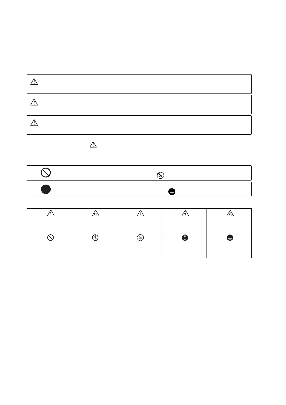
The following signs indicate prohibition and compulsory.
This sign indicates prohibited behavior (must not do).
For example, "Keep fire away" is indicated by .
This sign indicates a thing that is critical (must do).
For example, "it must be grounded" is indicated by .
The meaning of each pictorial sign is as follows.
CAUTION
Prohibited
CAUTION rotate ob-
ject
Disassembly is pro-
hibited
CAUTION HOT
KEEP FIRE AWAY
Danger Electric
shock risk
General instruction
Danger explosive
Earth ground
Page 9
For Safe Use
MITSUBISHI CNC is designed and manufactured solely for applications to machine tools to be used for industrial purposes.
Do not use this product in any applications other than those specified above, especially those which are substantially influential on the public interest or which are expected to have significant influence on human lives or properties.
1. Items related to prevention of electric shocks
WARNING
Do not open or remove the front cover while the power is ON or during operation. The high voltage terminals
and charged sections are exposed, and this could result in electric shocks.
Do not remove the front cover even when the power is OFF, except for the wiring works or periodic inspections. The inside of the controller and drive unit are charged, and this could result in electric shocks.
Always wait at least 15 minutes after turning the power OFF. Then, check the voltage with a tester, etc., before wiring works, inspections or connecting with peripheral devices. Failure to observe this could result in
electric shocks.
Earth ground the controller, drive unit and motor according to the local laws. (In Japan, ground the 200V
Series input products with Class C or higher protective grounding and the 400V Series input with Class D
or higher protective grounding.)
All wiring works, maintenance and inspections must be carried out by a qualified technician. Failure to observe this could result in electric shocks. Contact your nearby Service Center for replacing parts and servicing.
Wire the controller, drive unit and motor after installation. Failure to observe this could result in electric
shocks.
Do not operate the switches with wet hands. Failure to observe this could result in electric shocks.
Do not damage, apply excessive stress, place heavy things on or sandwich the cables. Failure to observe
this could result in electric shocks.
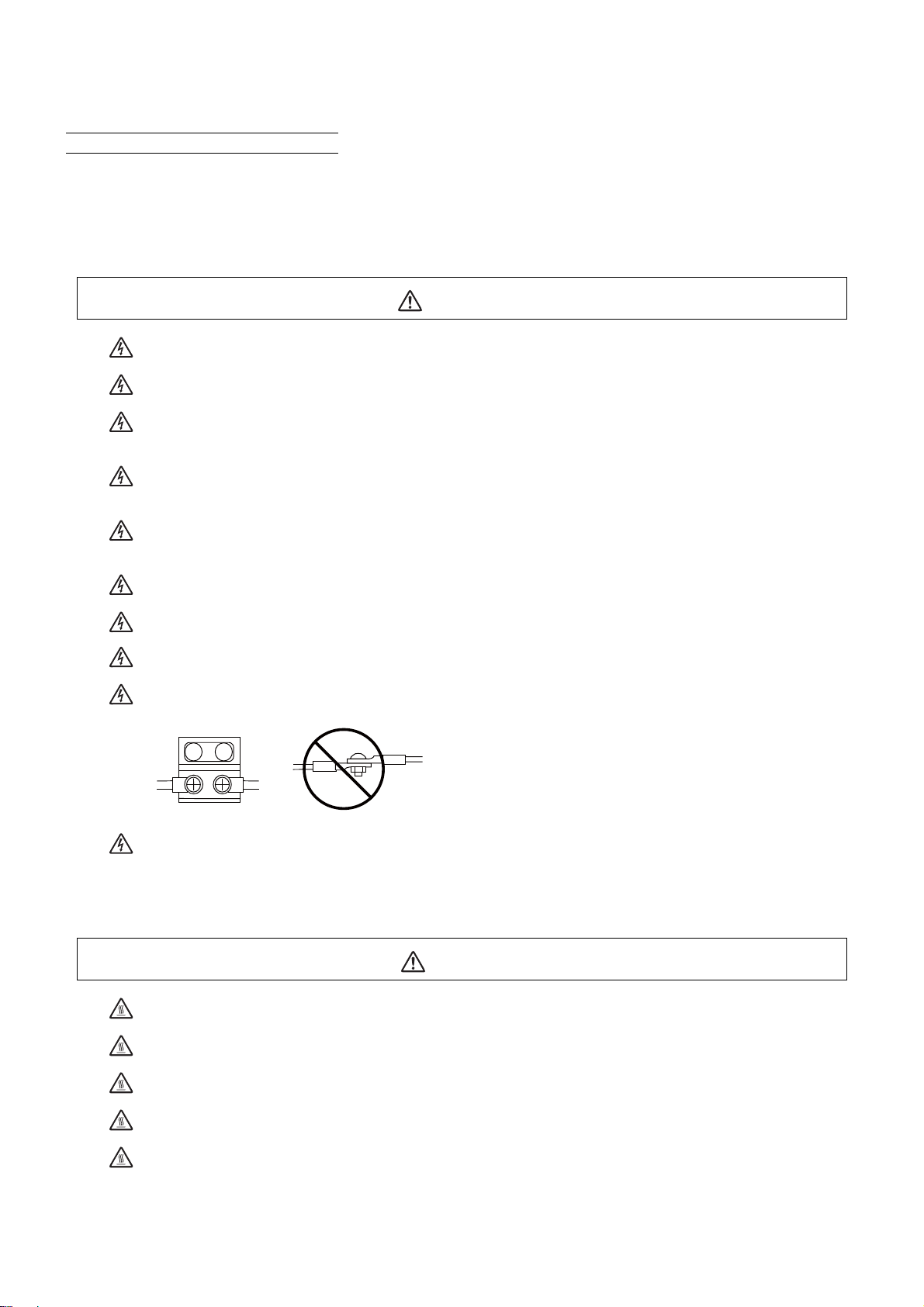
Insulate the power lead using a fixed terminal block. Failure to observe this could result in electric shocks.
Before starting maintenance or inspections, turn the main circuit power and control power both OFF. Wait
at least fifteen minutes until the CHARGE lamp turns OFF, and then confirm that the input and output voltage are zero using a tester, etc. Failure to observe this could lead to electric shocks.
2. Items related to prevention of fire
Install the controller, drive unit, motor and regenerative resistor on non-combustible material. Installation
directly on or near combustible materials could result in fires.
If any malfunction in the unit is observed, shut off the power at the unit’s power supply side. Continuous
flow of large current could result in fires.
Install an appropriate no fuse breaker (NFB) and contactor (MC) on the power input section of the drive unit
and configure the sequence that shuts the power off upon drive unit’s emergency stop or alarm.
When a breaker is shared for multiple power supply units, the breaker may not function upon short-circuit
failure in a small capacity unit. Do not share a breaker for multiple units as this is dangerous.
CAUTION
Incorrect wiring and connections could cause the devices to damage or burn.
Page 10

3. Items related to prevention of bodily injury or property damage
DANGER
When transporting or installing a built-in IPM spindle or linear servomotor, be careful so that your hand or
property is not trapped in the motors or other metal objects. Also keep the devices with low magnetic tolerance away from the product.
CAUTION
Do not apply voltages to the connectors or terminals other than voltages indicated in the connection and
setup manual for the controller or specifications manual for the drive unit. Failure to observe this could
cause bursting, damage, etc.
Incorrect connections could cause the devices to rupture or damage, etc. Always connect the cables to the
indicated connectors or terminals.
Incorrect polarity (+ -) could cause the devices to rupture or damage, etc.
Persons wearing medical devices, such as pacemakers, must stay away fro m th is un it. The e lect roma gne tic
waves could adversely affect the medical devices.
Fins on the rear of the unit, regenerative resistor and motor, etc., may be hot during operation and for a
while after the power has been turned OFF. Do not touch or place the parts and cables, etc. close to these
sections. Failure to observe this could result in burns.
Do not enter the machine’s movable range during automatic operation. Keep your hands, feet or face away
from the spindle during rotation.
4. Other items
Always follow the precautions below as well. Incorrect handling could result in faults, injuries or electric shocks, etc.
(1) Product and manual
CAUTION
For items described as "Restrictions" or "Usable State" in this manual, the instruction manual issued by
the machine tool builder (MTB) takes precedence over this manual.
Items not described in this manual must be interpreted as "not possible"
This manual is written on the assumption that all the applicable functions are included. Some of them, however, may not be available for your NC system. Refer to the specifications issued by the machine tool builder before use.
Refer to the manuals issued by the machine manufacturer for each machine tool explanation.
Some screens and functions may differ depending on the NC system (or its version), and some functions
may not be possible. Please confirm the specifications before use.
Do not connect NC system to the Internet-connected network.
To maintain the safety of the NC system against unauthorized access from external devices via the network,
take appropriate measures.
(2) Transportation and installation
CAUTION
Correctly transport the products according to the mass.
Use motor’s suspension bolts to transport the motor itself. Do not use it to transport the motor after installation onto the machine.
Do not stack the products exceeding the indicated limit.
Do not hold the cables, shaft or encoder when transporting the motor.
Page 11
CAUTION
Do not transport the controller or drive unit by suspending or holding the connected wires or cables.
Do not hold the front cover when transporting the unit, or the front cover could come off, causing the unit
to drop.
Install on a non-combustible place where the unit's or motor's mass can be withstood according to the instruction manual.
The motor does not have a complete water-proof (oil-proof) structure. Do not allow oil or water to contact
or enter the motor. Prevent the cutting chips from being accumulated on the motor as they easily soak up
oil.
When installing the motor facing upwards, take measures on the machine side so that gear oil, etc., will not
enter the motor shaft.
Do not remove the encoder from the motor. (The encoder installation screw is treated with sealing.)
Do not allow foreign matters, especially, conductive foreign matters such as screws or metal chips, or combu stibl e forei g n matt ers suc h as oil , to en ter the co ntroll er, drive unit or motor. Failure to observe this could
result in rupture or damage.
Do not get on the product or place heavy objects on it.
Provide prescribed distance between the controller/drive unit and inner surface of the control panel/other
devices.
Do not install or operate the controller, drive unit or motor that is damaged or has missing parts.
Take care not to cut hands, etc. with the heat radiating fins or metal edges.
Do not block the intake/outtake ports of the motor with the cooling fan.
Install the controller’s display section and operation board section on the spot where cutting oil will not
reach.
The controller, drive unit and motor are precision devices, so do not drop or apply thumping vibration and
strong impacts on them.
Store and use the units according to the environment conditions indicated in each specifications manual.
When disinfectants or insecticides must be used to treat wood packaging materials, always use methods
other than fumigation (for example, apply heat treatment at the minimum wood core temperature of 56 °C
for a minimum duration of 30 minutes (ISPM No. 15 (2009))).
If products such as units are directly fumigated or packed with fumigated wooden materials, halogen substances (including fluorine, chlorine , bromi ne and i o dine) c ontained in fumes may contribute to the erosion
of the capacitors. When exporting the products, make sure to comply with the laws and regulations of each
country.
Do not use the products in conjunction with any components that contain halogenated flame retardants
(bromine, etc). Failure to observe this may cause the erosion of the capacitors.
Securely fix the motor to the machine. The motor could come off during operation if insecurely fixed.
Always install the motor with reduction gear in the designated direction. Failure to observe this could result
in oil leaks.
Always install a cover, etc., over the shaft so that the rotary section of the motor cannot be touched during
motor rotation.
When installing a coupling to the servomotor shaft end, do not apply impacts by hammering, etc. The encoder could be damaged.
Use a flexible coupling when connecting with a ball screw, etc., and keep the shaft core deviation smaller
than the tolerable radial load of the shaft.
Do not use a rigid coupling as an excessive bending load may be applied on the shaft and could cause the
shaft to break.
Do not apply a load exceeding the tolerable level onto the motor shaft. The shaft or bearing could be damaged.
Before using this product after a long period of storage, please contact the Service Center.
Page 12
Following the UN recommendations, battery units and batteries should be transported based on the inter-
RA
RA
COM COM
Control
output
signal
Drive unit
Control
output
signal
Drive unit
(24VDC) (24VDC)
national regulations such as those determined by International Civil Aviation Organization (ICAO), International Air Transport Association (IATA), International Maritime Organization (IMO) and U.S. Department of
Transportation (DOT).
Install the unit in a place which can withstand its weight.
(3) Items related to wiring
Correctly wire this product. Failure to observe this could result in motor runaway, etc.
Do not install a phase advancing capacitor, surge absorber or radio noise filter on the output side of the
drive unit.
Correctly connect the output side (terminal U, V, W). The motor will not run properly if incorrectly connected.
Always install an AC reactor per each power supply unit.
Always install an appropriate breaker per each power supply unit. A breaker cannot be shared for multiple
power supply units.
Do not directly connect a commercial power supply to the motor. Failure to observe this could result in
faults.
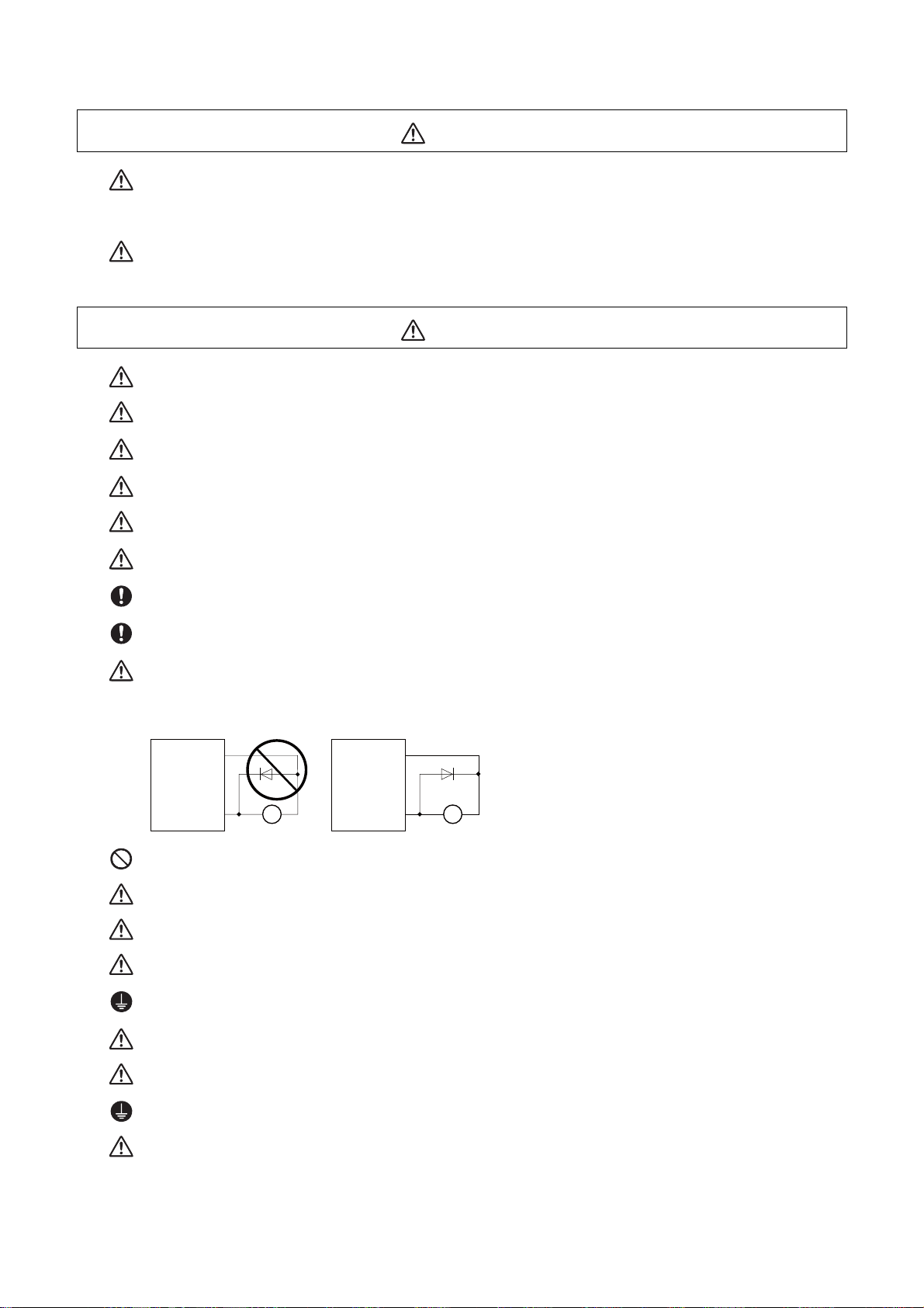
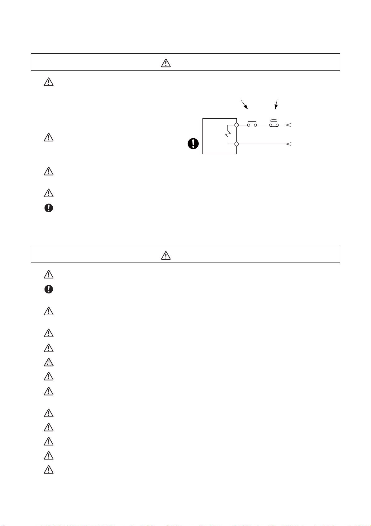
When using an inductive load such as relays, always connect a diode in parallel to the load as a noise
countermeasure.
When using a capacitive load such as a lamp, always connect a protective resistor serially to the load to
suppress rush currents.
Do not mistake the direction of the surge absorption diode to be installed on the DC relay for the control
output signal. If mistaken, the signal will not be output due to fault in the drive unit, and consequently the
protective circuit, such as emergency stop, could be disabled.
CAUTION
CAUTION
Do not connect or disconnect the connection cables between each unit while the power is ON.
Do not connect or disconnect the PCBs while the power is ON.
Do not pull the cables when connecting/disconnecting them.
Securely tighten the cable connector fixing screw or fixing mechanism. The motor could come off during
operation if insecurely fixed.
Always treat the shield cables indicated in the Connection Manual with grounding measures such as cable
clamps.
Separate the signal wire from the drive line or power line when wiring.
Use wires and cables whose wire diameter, heat resistance level and bending capacity are compatible with
the system.
Ground the device according to the requirements of the country where the device is to be used.
Wire the heat radiating fins and wires so that they do not contact.
Page 13
CAUTION
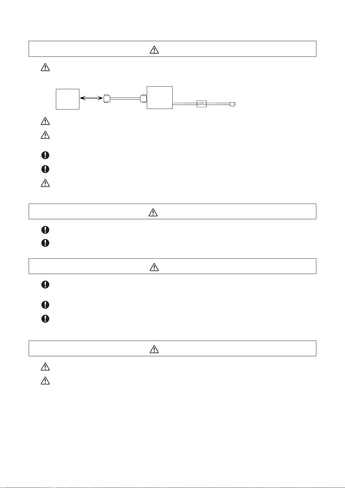
When using the RS-232C device as a peripheral device, caution must be paid for connector connection/disconnection. Always use a double-OFF type AC power supply switch on the device side, and connect/disconnect the connector with the AC power supply on the device side OFF.
(4) Set up
NC unit
RS-232C
Using a stabilized power supply without overcurrent protection may cause the unit's failure due to miswiring of 24V.
12V, 5V, and 3.3V output from connectors are to supply the power for dedicated peripheral devices. Do not
use for other equipment to supply the power since we do not guarantee the NC operation by voltage down
or noise sneaking.
When using an inductive load such as a relay, always connect a diode in parallel to the load to prevent a
counter-electromotive force.
When the rush current exceeds the maximum output current, always connect a protective resistor serially
to the load to suppress rush currents.
The wires from the surge absorber should be connected without extensions.
Device
Switch
AC socket
WARNING
Do not cancel the emergency stop before confirming the basic operation.
Always set the stored stroke limit. Failure to set this could result in collision with the machine end.
If the battery low warning is issued, save the machining programs, tool data and parameters in an input/
output device, and then replace the battery. When the battery alarm is issued, the machining programs, tool
data and parameters may be destroyed. Reload the data after replacing the battery.
Do not adjust the spindle when possible risks associated with adjustment procedures are not thoroughly
taken into consideration.
Be careful when touching spindle's rotating section, or your hand may be caught in or cut.
(5) Adjustments
Check and adjust programs and each parameter before starting operation. Failure to observe this could result in unpredictable operations depending on the machine.
Do not make drastic adjustments or changes as the operation could become unstable.
CAUTION
CAUTION
Page 14
(6) Usage
CAUTION
Install an external emergency stop circuit so that the operation can be stopped and the power turns OFF
immediately when unforeseen situation occurs. A contactor, etc., is required in addition to the shutoff function mounted in the controller.
Turn OFF the power immediately if any smoke, abnormal noise or odor is generated from the controller,
drive unit or motor.
Only a qualified technician may disassemble or repair this product.
Do not alter.
Use a noise filter, etc. to reduce the effect of electromagnetic disturbances in the case where electromagnetic disturbances could adversely affect the electronic devices used near the drive unit.
Use the drive unit, motor and each regenerative resistor with the designated combination. Failure to observe this could result in fires or faults.
The combination of the motor and drive unit that can be used is determined. Be sure to check the models
of motor and drive unit before test operation.
The brakes (electromagnetic brakes) mounted in the servomotor are used for the purpose of holding, and
must not be used for normal braking. Also, do not run the motor with the motor brake applied. Motor brake
is used for the purpose of holding.
For the system running via a timing belt, install a brake on the machine side so that safety can be ensured.
Be sure to confirm SERVO OFF (or READY OFF) when applying the electromagnetic brake. Also, be sure to
confirm SERVO ON prior to releasing the brake.
When using the DC OFF type electromagnetic brake, be sure to install a surge absorber on the brake terminal.
Do not connect or disconnect the cannon plug while the electromagnetic brake’s power is ON. The cannon
plug pins could be damaged by sparks.
After changing programs/parameters, or after maintenance/inspecti o n, alw ays ca r ry out a test o perat i on before starting actual operation.
Use the power that are complied with the power specification conditions (input voltage, input frequency,
tolerable time for instantaneous power interruption) indicated in each specifications manual.
When making encoder cables, do not mistake connection. Failure to observe this could result in malfunction, runaway or fire.
Surge absorber to be selected varies depending on input power voltage.
Always keep the touchscreen surface clean. When it gets dirty, remove the dirt immediately. Do not perform
any operation on the dirty touchscreen.
Pay close attention to the sequence operation when carrying out forced data setting (forced output) in the
I/F diagnosis screen during machine operation.
Page 15
(7) Troubleshooting
MBR EMG
Motor
Electromagnetic
brake
Shut off with motor
brake control output
Shut off with CNC brake
control PLC output
24VDC
Use a motor with electromagnetic brakes or
establish an external brake mechanism for the
purpose of holding; this serves as countermeasures for possible hazardous situation
caused by power failure or product fault.
Use a double circuit structure for the electromagnetic brake's operation circuit so that the
brakes will activate even when the external
emergency stop signal is issued.
The machine could suddenly restart when the power is restored after an instantaneous power failure, so
stay away from the machine. (Design the machine so that the operator safety can be ensured even if the
machine restarts.)
To secure the absolute position, do not shut off the servo drive uni t’s control p ower supp ly when i ts ba tter y
voltage drops (warning 9F) in the servo drive unit side.
If the battery voltage drop warning alarm occurs in the controller side, make sure to back up the machining
programs, tool data and parameters, etc. with the input/output device before replacing the battery. Depending on the level of voltage drop, memory loss could have happened. In that case, reload all the data backed
up before the alarm occurrence.
CAUTION
(8) Maintenance, inspection and part replacement
Periodically back up the programs, tool data and parameters to avoid potential data loss. Also, back up
those data before maintenance and inspections.
When replacing the battery on the controller side, the machining programs, tool data and parameters
should be backed up with the input/output device beforehand. In case the memory is damaged in replacing
the batteries, reload all the data backed up before replacing the battery.
The electrolytic capacitor’s capacity will drop due to deterioration. To prevent secondary damage due to
capacitor's faults, Mitsubishi recommends the electrolytic capacitor to be replaced approx. every five years
even when used in a normal environment. Contact the Service Center for replacements.
Never perform a megger test (measure the insulation resistance) of the drive unit. Failure to observe this
could lead to faults.
Do not replace parts or devices while the power is ON.
Do not short-circuit, charge, overheat, incinerate or disassemble the battery.
There may be a unit filled with substitute Freon in the heat radiating fins of the 37kW or smaller unit. Be
careful not to break the heat radiating fins during maintenance or replacement.
Connect the encoder (CN2/CN3) immediately after the installation of the servo drive unit. In addition, when
a battery box is used, immediately connect to the BTA/BTB connector. (prevention of absolute position data
lost)
Replace the batteries with new ones immediately after the battery voltage drop alarm (9F) has been output.
CAUTION
Replace the batteries while applying the drive unit’s control power.
Replace the batteries with new ones that are in their recommended use period.
Wrong connection may cause liquid leakage, heat generation and/or explosion.
Do not mix new batteries with used ones or mix different types of batteries.
Page 16
(9) Disposal
CAUTION
Take the batteries and backlights for LCD, etc., off from the controller, drive unit and motor, and dispose of
them as general industrial wastes.
Do not alter or disassemble controller, drive unit, or motor.
Collect and dispose of the spent batteries and the backlights for LCD according to the local laws.
Dispose the spent cooling fan according to local laws.
(10) General precautions
To explain the details, drawings given in the instruction manual, etc., may show the unit with the cover
or safety partition removed. When operating the product, always place the cover or partitions back to
their original position, and operate as indicated in the instruction manual, etc.
Page 17

Page 18

Treatment of waste
The following two laws will apply when disposing of this product. Considerations must be made to each law.
The following laws are in effect in Japan. Thus, when using this product overseas, the local laws will have a
priority. If necessary, indicate or notify these laws to the final user of the product.
(1) Requirements for "Law for Promotion of Effective Utilization of Resources"
(a) Recycle as much of this product as possible when finished with use.
(b) When recycling, often parts are sorted into steel scraps and electric parts, etc., and sold to scrap
contractors. Mitsubishi recommends sorting the product and selling the members to appropriate
contractors.
(2) Requirements for "Law for Treatment of Waste and Cleaning"
(a) Mitsubishi recommends recycling and selling the pr oduct when n o longer needed a ccording to item
(1) above. The user should make an effort to reduce waste in this manner.
(b) When disposing a product that cannot be resold, it shall be treated as a waste product.
(c) The treatment of industrial waste must be commissioned to a licensed industrial waste treatment
contractor, and appropriate measures, including a manifest co ntrol, must be taken.
(d) Batteries correspond to "primary batteries", and must be disposed of according to local disposal
laws.
Page 19

Page 20

Disposal
(Note) This symbol mark is for EU countries only.
This symbol mark is according to the directive 2006/66/EC Article 20 Information for endusers and Annex II.
Your MITSUBISHI ELECTRIC product is designed and manufactured with high quality materials and
components which can be recycled and/or reused.
This symbol means that batteries and accumulators, at their end-of-life, should be disposed of
separately from your household waste.
If a chemical symbol is printed beneath the symbol shown above, this chemical symbol means that the
battery or accumulator contains a heavy metal at a certain concentration. This will be indicated as
follows:
Hg: mercury (0,0005%), Cd: cadmium (0,002%), Pb: lead (0,004%)
In the European Union there are separate collection systems for used batteries and accumulators.
Please, dispose of batteries and accumulators correctly at your local community waste collection/
recycling centre.
Please, help us to conserve the environment we live in!
Page 21

Page 22

Trademarks
MELDAS, MELSEC, EZSocket, EZMotion, iQ Platform, MELSEC iQ-R, MELSOFT, GOT, CC-Link, CC-Link/LT,
CC-Link IE, CC-Link IE/field, EcoMonitorLight and SLMP are either trademarks or registered trademarks of
Mitsubishi Electric Corporation in Japan and/or other countries.
Ethernet is a registered trademark of Xerox Corporation in the United States and/or other countries.
Microsoft®, Windows®, SQL Server® and Access® are either trademarks or registered trademarks of Microsoft
Corporation in the United States and/or other countries.
SD logo and SDHC logo are either registered trademarks or trademarks of LLC.
UNIX is a registered trademark of The Open Group in the United States and/or other countries.
Intel® and Pentium® are either trademarks or registered trademarks of Intel Corporation in the United States and/or
other countries.
MODBUS® is either a trademark or a registered trademark of Schneider Electric USA, Inc. or the affiliated
companies in Japan and/or other countries.
EtherNet/IP is a trademark of Open DeviceNet Vendor Association,Inc.
PROFIBUS-DP and PROFINET are either trademarks of Profibus International.
Oracle® is a registered trademark of Oracle Corporation, the subsidiaries, or the affiliated companies in the United
States and /or other countries.
VNC is a registered trademark of RealVNC Ltd. in the United States and other countries.
Other company and product names that appear in this manual are trademarks or registered trademarks of the
respective companies.
Page 23

Page 24

本製品の取扱いについて
( 日本語 /Japanese)
本製品は工業用 ( クラス A) 電磁環境適合機器です。販売者あるいは使用者はこの点に注意し、住商業環境以外で
の使用をお願いいたします。
Handling of our product
(English)
This is a class A product. In a domestic environment this product may cause radio interference in which case the
user may be required to take adequate measures.
본 제품의 취급에 대해서
( 한국어 /Korean)
이 기기는 업무용 (A 급 ) 전자파적합기기로서 판매자 또는 사용자는 이 점을 주의하시기 바라며 가정외의 지역에
서 사용하는 것을 목적으로 합니다 .
Page 25

Page 26

Contents
1 System Basic Configuration ....................................................................................................................... 1
1.1 System Basic Configuration Drawing ....................................................................................................................... 2
1.2 General Connection Diagram ................................................................................................................................... 4
1.2.1 General Connection Diagram [M800W] ........................................................................................................... 4
1.2.2 General Connection Diagram [M80W] ............................................................................................................. 7
1.2.3 General Connection Diagram [M800S] .......................................................................................................... 10
1.2.4 General Connection Diagram [M80]............................................................................................................... 11
1.2.5 General Connection Diagram [E80] ............................................................................................................... 13
1.3 How to Check the System Configuration ................................................................................................................ 14
1.3.1 System Configuration Screen ........................................................................................................................ 14
1.3.2 Option Display Screen ................................................................................................................................... 17
1.4 Each Unit Status Display ........................................................................................................................................ 18
1.4.1 Control Unit .................................................................................................................................................... 18
1.4.2 Personal Computer Unit................................................................................................................................. 21
1.4.3 Operation Panel I/O Unit................................................................................................................................ 22
1.4.4 Remote I/O Unit ............................................................................................................................................. 25
1.4.5 Communication Expansion Unit ..................................................................................................................... 27
1.4.5.1 CC-Link Expansion Unit ....................................................................................................................... 27
1.4.5.2 PROFIBUS-DP Expansion Unit............................................................................................................ 28
1.4.5.3 CC-Link IE Field ................................................................................................................................... 29
1.4.5.4 EtherNet/IP........................................................................................................................................... 30
1.4.6 7-segment LEDs on the Control Unit ............................................................................................................. 31
1.4.6.1 Normal State Display............................................................................................................................ 31
1.4.6.2 Error Display at NC Startup.................................................................................................................. 31
1.4.6.3 Display when an Alarm Occurs ............................................................................................................ 32
2 Daily Maintenance and Periodic Maintenance ........................................................................................ 41
2.1 Daily Maintenance .................................................................................................................................................. 43
2.1.1 Touchscreen .................................................................................................................................................. 43
2.1.2 Escutcheon .................................................................................................................................................... 43
2.2 Periodic Maintenance ............................................................................................................................................. 44
2.2.1 List of Durable Parts....................................................................................................................................... 44
2.2.2 List of Replacing Parts ................................................................................................................................... 44
2.2.3 Durable Parts Replacement ........................................................................................................................... 45
2.2.3.1 Control Unit Battery .............................................................................................................................. 45
2.2.3.2 Personal Computer Unit Cooling Fan................................................................................................... 47
2.2.4 Replacing Fuse .............................................................................................................................................. 48
3 Maintenance of the Drive Unit................................................................................................................... 51
3.1 Periodic Inspections................................................................................................................................................ 52
3.2 Durable Parts.......................................................................................................................................................... 53
3.3 Adding and Replacing Units and Parts ................................................................................................................... 54
3.3.1 MDS-E/EH Series .......................................................................................................................................... 54
3.3.1.1 Replacing the Drive Unit....................................................................................................................... 54
3.3.1.2 Replacing the Unit Fan......................................................................................................................... 55
3.3.1.3 Replacing the Battery ........................................................................................................................... 57
3.3.2 MDS-EJ/EJH Series....................................................................................................................................... 60
3.3.2.1 Replacing the Drive Unit....................................................................................................................... 60
3.3.2.2 Replacing the Unit Fan......................................................................................................................... 60
3.3.2.3 Replacing the Battery ........................................................................................................................... 66
3.3.3 MDS-EM/EMH Series .................................................................................................................................... 69
3.3.3.1 Replacing the Drive Unit....................................................................................................................... 69
3.3.3.2 Replacing the Fan Unit......................................................................................................................... 70
3.3.3.3 Replacing the Battery ........................................................................................................................... 71
4 Failure Diagnosis ....................................................................................................................................... 75
4.1 Introduction ............................................................................................................................................................. 76
4.2 Failure Diagnosis Procedure .................................................................................................................................. 76
4.3 Diagnosis Based on the Alarm ............................................................................................................................... 77
4.3.1 How To Check the Alarm Information ............................................................................................................ 77
4.3.2 Alarm History.................................................................................................................................................. 79
4.3.3 Alarm Message Details .................................................................................................................................. 81
4.4 Diagnosis Based on the I/F Diagnosis Screen ....................................................................................................... 82
Page 27

4.4.1 I/F Diagnosis Screen...................................................................................................................................... 82
4.4.1.1 Displaying the PLC Device Data ........................................................................................................... 84
4.4.1.2 Carrying Out Modal Output ................................................................................................................... 85
4.4.1.3 Carrying Out One-shot Output .............................................................................................................. 86
4.4.2 List of Devices for PLC Uses ......................................................................................................................... 87
4.5 Diagnosis Based on the Self Diagnosis Screen ..................................................................................................... 88
4.5.1 Self Diagnosis Screen.................................................................................................................................... 88
4.6 Diagnosis Based on the Data Sampling Screen..................................................................................................... 93
4.7 Diagnosis Based on the Drive Monitor Screen ....................................................................................................... 94
4.7.1 Drive Monitor Screen (Servo Unit) ................................................................................................................. 94
4.7.2 Drive Monitor Screen (Spindle Unit)............................................................................................................... 99
4.7.3 Drive Monitor Screen (Power Supply Unit) .................................................................................................. 104
4.7.4 Drive Monitor Screen (Synchronous Error) .................................................................................................. 106
4.7.5 Clearing the Alarm History on Drive Monitor Screen ................................................................................... 107
4.8 NC Memory Diagnosis Screen ............................................................................................................................. 108
4.9 Safety Observation Screen................................................................................................................................... 110
4.9.1 Safety Observation Screen (Configuration Diagnosis)................................................................................. 110
4.9.2 Safety Observation Screen (Signal Monitor)................................................................................................ 112
4.9.3 Safety Observation Screen (Drive Monitor) ................................................................................................. 114
4.9.4 Safety Observation Screen (Version Display).............................................................................................. 117
4.10 Servo Diagnosis Screen ..................................................................................................................................... 118
4.11 Diagnosis Data Collection Setting ...................................................................................................................... 121
4.11.1 Starting the Data Collection ....................................................................................................................... 123
4.11.2 Stopping the Data Collection.............................................................................................
4.11.3 Clearing the Collected Data ....................................................................................................................... 124
4.11.4 Referring to the Collected Data.................................................................................................................. 124
4.11.5 Display Delay Function for Communication Errors and Servo/Spindle Alarms .......................................... 127
4.12 Application Error Detection ................................................................................................................................. 128
4.13 IP Address Resetting Procedure at Disabled Network Communication [M800W/M80W Series Only]............... 129
4.13.1 Connectable Control Unit IP Address List Screen ..................................................................................... 129
4.13.2 Resetting Procedure .................................................................................................................................. 130
4.13.3 Message..................................................................................................................................................... 131
4.14 Field Network Diagnostics Function ................................................................................................................... 132
4.14.1 Diagnosis Procedure.................................................................................................................................. 133
4.14.1.1 Statistical Information in Packet Transmission and Reception..........................................................133
4.14.1.2 Protocol-Specific Information ............................................................................................................ 135
4.14.2 Diagnosis Command.................................................................................................................................. 136
4.14.2.1 Clearing Statistical Information of Packet Transmission and Reception ........................................... 136
4.14.2.2 Error Code List .................................................................................................................................. 137
......................... 123
5 Troubleshooting....................................................................................................................................... 139
5.1 Troubleshooting .................................................................................................................................................... 140
5.1.1 Possible Causes of Trouble ......................................................................................................................... 141
6 Replacing Each Unit ................................................................................................................................ 143
6.1 Data Backup and Restoration............................................................................................................................... 144
6.1.1 All Backup .................................................................................................................................................... 145
6.1.2 All Restoration.............................................................................................................................................. 147
6.2 Control Unit........................................................................................................................................................... 149
6.3 Display Unit........................................................................................................................................................... 151
6.4 Personal Computer Unit ....................................................................................................................................... 156
6.5 Keyboard Unit ....................................................................................................................................................... 157
6.6 Operation Panel I/O Unit....................................................................................................................................... 164
6.7 Remote I/O Unit .................................................................................................................................................... 166
6.8 Function Expansion Unit....................................................................................................................................... 168
6.8.1 Encoder (Manual Pulse Generator) I/F Expansion Unit [M800W/M80W] .................................................... 168
6.8.2 Functional Safety Expansion Unit [M80] ...................................................................................................... 169
6.9 Communication Expansion Unit............................................................................................................................ 170
6.10 Built-in Disk of the Display Unit........................................................................................................................... 172
6.11 SD Card .............................................................................................................................................................. 173
6.12 USB memory ...................................................................................................................................................... 174
6.13 MITSUBISHI CNC Machine Operation Panel ..................................................................................................... 175
Page 28

1
1
IB-1501273-F
System Basic Configuration
Page 29
M800/M80/E80 Series Maintenance Manual
1 System Basic Configuration
1System Basic Configuration
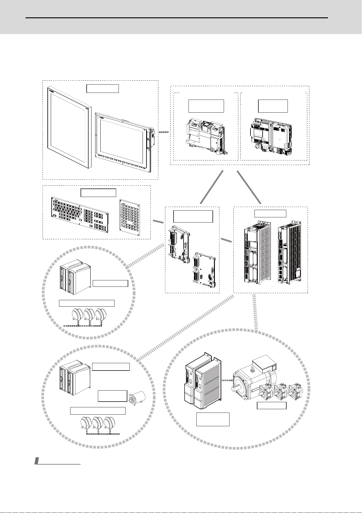
1.1 System Basic Configuration Drawing
For M800W/M80W
Display unit
Keyboard unit
Windows-based display non-Windows-based display
Personal
computer unit
Operation panel
I/O unit
Grahpic
control unit
Control unit
Remote I/O unit
Manual pulse penerator
Remote I/O unit
Synchronous
feed encoder
Manual pulse generator
M800W M80W
Motor group
Servo/Spindle
drive unit
Note
(1) For the drive unit configuration, refer to the drive unit's manual.
IB-1501273-F
2
Page 30
M800/M80/E80 Series Maintenance Manual
1 System Basic Configuration
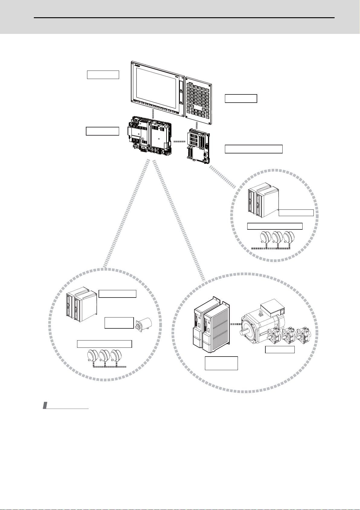
For M800S/M80/E80
Display unit
(Control unit is added onto
back of display unit.)
Control unit
Keyboard unit
(Operation panel I/O unit is added
onto back of keyboard unit.)
Operation panel I/O unit
Remote I/O unit
Manual pulse penerator
Remote I/O unit
Synchronous
feed encoder
Manual pulse generator
Note
(1) For the drive unit configuration, refer to the drive unit's manual.
Motor group
Servo/Spindle
drive unit
3
IB-1501273-F
Page 31

M800/M80/E80 Series Maintenance Manual
1 System Basic Configuration
SIO
1ch:J030
2ch:J031
2ch
RS232C
SKIP
RIO2
SD
RIO3
GDI
LAN
J303
Network
FCU8-EX56x
J100
SD
FCU8-DX2xx/DX6xx
/DX4xx
RIO1
DCIN
J070/071
(EcoMonitor)
OPTH1
OPTH2
J395/J396
J395/J396
EMG
J120
Max. 8 points
J070/071
J070/071
J210
DI:CJ31/33
DO:CJ32/34
RIO1
DCIN
RIO2
DI:CJ31/33
DO:CJ32/34
RIO1
DCIN
RIO2
J350/351
J350/351
J070/071
J070/071
J210
DI:CJ31/33
DO:CJ32/34
RIO1
DCIN
RIO2
DI:CJ31/33
DO:CJ32/34
RIO1
DCIN
RIO2
J350/351
J350/351
(R2-TM)
(R2-TM)
FG
5V:J023/J024/J025
12V:J020/J021/J022
L1 L2
L3
(NFB)
DCOUT
FG
ACIN
CP
MC
ON OFF
MC
MC
J350/351
J350/351
J350/351
J350/351
FCU8-EX54x
EXT1
EXT3
G430
device
Skip signal input
Communication
expansion unit
Control unit
Max. 32 units for each port
Remote I/O unit
Remote I/O unit
Remote I/O unit
Remote I/O unit
24VDC
Energy measuring units
Drive units
Stored in control unit
To the next
remote I/O or
terminator
connector
To the next
remote I/O or
terminator
connector
Emergency
stop switch
SD
memory
card
24VDC24VDC
24VDC24VDC
Machine
control
relay/contact
Machine
control
relay/contact
24VDC
Manual pulse
generator (5V/12V)
Machine operation
panel made by the
machine tool builder
Dotted lines indicate the sections prepared by the machine tool builder.
<> Angle brackets indicates attached cable of unit.
No-fuse breaker
24VDC stabilized
power supply
Function
expansion unit
(Note 1)
Handy terminal
FCU8-EX56x
FCU8-EX54x
FCU8-MA041/MU042
MA041:M850W
MU042:M830W
RIO8
AIO
J026/J027
J220
EXT2
EXT4
RIO4
RIO6
RIO7
RIO5
Communication
expansion unit
Function
expansion unit
Analog input : 4 points
Analog output : 2 points
Manual pulse
generator (5V)
J120
ON/OFF
CFAST
CFast
LVDS1
USB2-1
USB2-2
FCU8-PC231
LAN
J303
MENUKEY
RIO3EXT
ON
OFF
G170
MPG
INV
RS232C
USB-RS232C
GDI
KEYUSB
RIO3
J303
NCKB
KEYUSB
J210
J291
J210
LVDS2
SD
DCIN
J070/071
EMG
USB
USB3-2
USB3-1
USB2-4
USB2-3
USB2-6
USB2-5
FCU8-DX2xx/DX6xx/DX4xx
CJ71
FCU8-CF001-001
DCIN
J070/071
Network
CG31
CG32
FCU8-DX830/837
CG33
CG34
SDI
Max. 8 points
DI:CJ31/33
DO:CJ32/34
RIO1
DCIN
RIO2
J350/351
J350/351
(R2-TM)
J210
FCU8-KB92x
FCU8-KB941/KB931
<G460>
24VDC
MITSUBISHI CNC Machine Operation Panel
Emergency
stop switch
Personal computer unit
device
conversion
24VDC
USB memory
24VDC
Remote I/O unit
24VDC
Operation panel I/O unit
Safety signal input
DX830:
No safety signal input
DX837:
With safety signal input
Stored in
personal computer unit
CFast unit
(Safety signal input is
DX837 only.)
To the next remote I/O
or terminator connector
Added onto back of
display unit
SD
memory
card
24VDC
Machine
control
relay/contact
Backlight
I/F PCB
FCU8-KB04x/KB083
<G402>
<J09x>
USB
SD
<J292>
<J190>
<J290>
<J081>
<J420>
Keyboard unit
(Note 2)
15-type LCD
with touch panel
Display unit
Menukey
FCU8-DU181-34
1.2 General Connection Diagram
1.2.1 General Connection Diagram [M800W]
Windows-based display (15-type)
(Note 1) For information on how to connect the drive unit, refer to the drive unit's manual.
(Note 2) When using a keyboard unit, install the operation panel I/O unit on the back of the keyboard unit.
Note
(1) For the connection of MITSUBISHI CNC machine operation panel, refer to "M800W/M80W Series Connection and Set-
up Manual".
IB-1501273-F
4
Page 32

M800/M80/E80 Series Maintenance Manual
1 System Basic Configuration
SIO
1ch:J030
2ch:J031
2ch
RS232C
SKIP
RIO2
SD
RIO3
GDI
LAN
J303
Network
FCU8-EX56x
J100
SD
FCU8-DX2xx/DX6xx
/DX4xx
RIO1
DCIN
J070/071
(EcoMonitor)
OPTH1
OPTH2
J395/J396
J395/J396
EMG
J120
Max. 8 points
J070/071
J070/071
J210
DI:CJ31/33
DO:CJ32/34
RIO1
DCIN
RIO2
DI:CJ31/33
DO:CJ32/34
RIO1
DCIN
RIO2
J350/351
J350/351
J070/071
J070/071
J210
DI:CJ31/33
DO:CJ32/34
RIO1
DCIN
RIO2
DI:CJ31/33
DO:CJ32/34
RIO1
DCIN
RIO2
J350/351
J350/351
(R2-TM)
(R2-TM)
FG
5V:J023/J024/J025
12V:J020/J021/J022
L1 L2
L3
(NFB)
DCOUT
FG
ACIN
CP
MC
ON OFF
MC
MC
J350/351
J350/351
J350/351
J350/351
FCU8-EX54x
EXT1
EXT3
G430
device
Skip signal input
Communication
expansion unit
Control unit
Max. 32 units for each port
Remote I/O unit
Remote I/O unit
Remote I/O unit
Remote I/O unit
24VDC
Energy measuring units
Drive units
Stored in control unit
To the next
remote I/O or
terminator
connector
To the next
remote I/O or
terminator
connector
Emergency
stop switch
SD
memory
card
24VDC24VDC
24VDC24VDC
Machine
control
relay/contact
Machine
control
relay/contact
24VDC
Manual pulse
generator (5V/12V)
Machine operation
panel made by the
machine tool builder
Dotted lines indicate the sections prepared by the machine tool builder.
<> Angle brackets indicates attached cable of unit.
No-fuse breaker
24VDC stabilized
power supply
Function
expansion unit
(Note 1)
Handy terminal
FCU8-EX56x
FCU8-EX54x
FCU8-MA041/MU042
MA041:M850W
MU042:M830W
RIO8
AIO
J026/J027
J220
EXT2
EXT4
RIO4
RIO6
RIO7
RIO5
Communication
expansion unit
Function
expansion unit
Analog input : 4 points
Analog output : 2 points
Manual pulse
generator (5V)
J120
ON/OFF
CFAST
CFast
LVDS1
USB2-1
USB2-2
FCU8-PC231
LAN
J303
MENUKEY
RIO3EXT
ON
OFF
G170
MPG
INV
RS232C
USB-RS232C
GDI
KEYUSB
RIO3
J303
NCKB
KEYUSB
J210
J291
J210
LVDS2
SD
DCIN
J070/071
EMG
USB
USB3-2
USB3-1
USB2-4
USB2-3
USB2-6
USB2-5
FCU8-DX2xx/DX6xx/DX4xx
CJ71
FCU8-CF001-001
DCIN
J070/071
Network
CG31
CG32
FCU8-DX830/837
CG33
CG34
SDI
Max. 8 points
DI:CJ31/33
DO:CJ32/34
RIO1
DCIN
RIO2
J350/351
J350/351
(R2-TM)
J210
FCU8-KB92x
FCU8-KB941/KB931
<G460>
24VDC
MITSUBISHI CNC Machine Operation Panel
Emergency
stop switch
Personal computer unit
device
conversion
24VDC
USB memory
24VDC
Remote I/O unit
24VDC
Operation panel I/O unit
Safety signal input
DX830:
No safety signal input
DX837:
With safety signal input
Stored in
personal computer unit
CFast unit
(Safety signal input is
DX837 only.)
To the next remote I/O
or terminator connector
Added onto back of
display unit
SD
memory
card
24VDC
Machine
control
relay/contact
Backlight
I/F PCB
<J09x>
<J292>
<J190>
<J290>
<G195>
<J420>
FCU8-EP201-2
USB
SD
PCUSB
19-type LCD
Side memory I/F unit
wth touch panel
Display unit
FCU8-DU191-75
FCU8-DU192-75
Windows-based display (19-type)
(Note 1) For information on how to connect the drive unit, refer to the drive unit's manual.
(1) For the connection of MITSUBISHI CNC machine operation panel, refer to "M800W/M80W Series Connection and Set-
Note
up Manual".
5
IB-1501273-F
Page 33

M800/M80/E80 Series Maintenance Manual
1 System Basic Configuration
SIO
1ch:J030
2ch:J031
2ch
RS232C
SKIP
RIO2
SD
RIO3
GDI
LAN
J303
Network
FCU8-EX56x
J100
SD
FCU8-DX2xx/DX6xx
/DX4xx
RIO1
DCIN
J070/071
(EcoMonitor)
OPTH1
OPTH2
J395/J396
J395/J396
EMG
J120
Max. 8 points
J070/071
J070/071
J210
DI:CJ31/33
DO:CJ32/34
RIO1
DCIN
RIO2
DI:CJ31/33
DO:CJ32/34
RIO1
DCIN
RIO2
J350/351
J350/351
J070/071
J070/071
J210
DI:CJ31/33
DO:CJ32/34
RIO1
DCIN
RIO2
DI:CJ31/33
DO:CJ32/34
RIO1
DCIN
RIO2
J350/351
J350/351
(R2-TM)
(R2-TM)
FG
5V:J023/J024/J025
12V:J020/J021/J022
L1 L2
L3
(NFB)
DCOUT
FG
ACIN
CP
MC
ON OFF
MC
MC
J350/351
J350/351
J350/351
J350/351
FCU8-EX54x
EXT1
EXT3
G430
device
Skip signal input
Communication
expansion unit
Control unit
Max. 32 units for each port
Remote I/O unit
Remote I/O unit
Remote I/O unit
Remote I/O unit
24VDC
Energy measuring units
Drive units
Stored in control unit
To the next
remote I/O or
terminator
connector
To the next
remote I/O or
terminator
connector
Emergency
stop switch
SD
memory
card
24VDC24VDC
24VDC24VDC
Machine
control
relay/contact
Machine
control
relay/contact
24VDC
Manual pulse
generator (5V/12V)
Machine operation
panel made by the
machine tool builder
Dotted lines indicate the sections prepared by the machine tool builder.
<> Angle brackets indicates attached cable of unit.
No-fuse breaker
24VDC stabilized
power supply
Function
expansion unit
(Note 1)
Handy terminal
FCU8-EX56x
FCU8-EX54x
FCU8-MA041/MU042
MA041:M850W
MU042:M830W
RIO8
AIO
J026/J027
J220
EXT2
EXT4
RIO4
RIO6
RIO7
RIO5
Communication
expansion unit
Function
expansion unit
Analog input : 4 points
Analog output : 2 points
Manual pulse
generator (5V)
J070/071
DI:CJ31/33
DO:CJ32/34
RIO1
DCIN
RIO2
<J09x>
USB_F
SDC_F
USB_B
SDC_B
<J08x>
FCU8-GC211
RIO3EXT
RS232C
CJ71
FCU8-DX730
CG31
MPG
CG32
NCKB
CG33
CG34
LAN1
J303
Network
LAN2
J303
J210
G402
J210
EMG
DCIN
J070/071
LCD
MENUKEY
TP
BL
FRONT
ENC
ON
OFF
CJ71
J010
SIO
FCU8-DX2xx/DX6xx/DX4xx
max. 29 units
J170
<J421>
RIO1
J210
FCU8-KB92x
FCU8-KB941/KB931
<G460>
24VDC
MITSUBISHI CNC Machine Operation Panel
24VDC
Remote I/O unit
(Note 2)
Emergency
stop switch
Graphic control unit
device
24VDC
24VDC
Operation panel I/O unit
Menu key
Display unit
Memory mediums
Front memory I/F card
Keyboard unit
(Note 3)
FCU8-KB04x/083
<J421>
10.4-type:FCU8-DU141-31
15-type:FCU8-DU181-31
Non-Windows-based display (10.4-type/15-type)
I/O unit.
(Note 1) For information on how to connect the drive unit, refer to the drive unit's manual.
(Note 2) When connecting a remote I/O unit to the 3rd RIO channel, insert it between the control unit and operation panel
(Note 3) There is no need to connect a terminator R2-TM to the graphic control unit.
Note
(1) For the connection of MITSUBISHI CNC machine operation panel, refer to "M800W/M80W Series Connection and Set-
IB-1501273-F
up Manual".
6
Page 34

M800/M80/E80 Series Maintenance Manual
1 System Basic Configuration
SIO
1ch:J030
2ch:J031
2ch
RS232C
SKIP
RIO2
SD
RIO3
GDI
LAN
J303
Network
FCU8-EX56x
J100
SD
FCU8-DX2xx/DX6xx
/DX4xx
RIO1
DCIN
J070/071
(EcoMonitor)
OPTH1
OPTH2
J395/J396
J395/J396
EMG
J120
Max. 8 points
J070/071
J070/071
J210
DI:CJ31/33
DO:CJ32/34
RIO1
DCIN
RIO2
DI:CJ31/33
DO:CJ32/34
RIO1
DCIN
RIO2
J350/351
J350/351
J070/071
J070/071
J210
DI:CJ31/33
DO:CJ32/34
RIO1
DCIN
RIO2
DI:CJ31/33
DO:CJ32/34
RIO1
DCIN
RIO2
J350/351
J350/351
(R2-TM)
(R2-TM)
FG
5V:J023/J024/J025
12V:J020/J021/J022
L1 L2
L3
(NFB)
DCOUT
FG
ACIN
CP
MC
ON OFF
MC
MC
J350/351
J350/351
J350/351
J350/351
FCU8-EX54x
EXT1
EXT3
G430
device
Skip signal input
Communication
expansion unit
Control unit
Max. 32 units for each port
Remote I/O unit
Remote I/O unit
Remote I/O unit
Remote I/O unit
24VDC
Energy measuring units
Drive units
Stored in control unit
To the next
remote I/O or
terminator
connector
To the next
remote I/O or
terminator
connector
Emergency
stop switch
SD
memory
card
24VDC24VDC
24VDC24VDC
Machine
control
relay/contact
Machine
control
relay/contact
24VDC
Manual pulse
generator (5V/12V)
Machine operation
panel made by the
machine tool builder
Dotted lines indicate the sections prepared by the machine tool builder.
<> Angle brackets indicates attached cable of unit.
No-fuse breaker
24VDC stabilized
power supply
Function
expansion unit
(Note 1)
Handy terminal
FCU8-MU044
RIO4/M
BTBOX
J120
ON/OFF
CFAST
CFast
LVDS1
USB2-1
USB2-2
FCU8-PC231
LAN
J303
MENUKEY
RIO3EXT
ON
OFF
G170
MPG
INV
RS232C
USB-RS232C
GDI
KEYUSB
RIO3
J303
NCKB
KEYUSB
J210
J291
J210
LVDS2
SD
DCIN
J070/071
EMG
USB
USB3-2
USB3-1
USB2-4
USB2-3
USB2-6
USB2-5
FCU8-DX2xx/DX6xx/DX4xx
CJ71
FCU8-CF001-001
DCIN
J070/071
Network
CG31
CG32
FCU8-DX830/837
CG33
CG34
SDI
Max. 8 points
DI:CJ31/33
DO:CJ32/34
RIO1
DCIN
RIO2
J350/351
J350/351
(R2-TM)
J210
FCU8-KB92x
FCU8-KB941/KB931
<G460>
24VDC
MITSUBISHI CNC Machine Operation Panel
Emergency
stop switch
Personal computer unit
device
conversion
24VDC
USB memory
24VDC
Remote I/O unit
24VDC
Operation panel I/O unit
Safety signal input
DX830:
No safety signal input
DX837:
With safety signal input
Stored in
personal computer unit
CFast unit
(Safety signal input is
DX837 only.)
To the next remote I/O
or terminator connector
Added onto back of
display unit
SD
memory
card
24VDC
Machine
control
relay/contact
Backlight
I/F PCB
FCU8-KB04x/KB083
<G402>
<J09x>
USB
SD
<J292>
<J190>
<J290>
<J081>
<J420>
Keyboard unit
(Note 2)
15-type LCD
with touch panel
Display unit
Menukey
FCU8-DU181-36
1.2.2 General Connection Diagram [M80W]
Windows-based display (15-type)
(Note 1) For information on how to connect the drive unit, refer to the drive unit's manual.
(Note 2) When using a keyboard unit, install the operation panel I/O unit on the back of the keyboard unit.
(1) For the connection of MITSUBISHI CNC machine operation panel, refer to "M800W/M80W Series Connection and Set-
(2) When the handle of handy terminal is used, connect ENC connector of G430 cable to MPG connector of the operation
Note
up Manual".
panel I/O unit.
Because the pin assignment of ENC connector of G430 is different from that of MPG connector of the operation panel
I/O unit, conversion is required.
The conversion cable needs to be prepared by the MTB.
7
IB-1501273-F
Page 35

M800/M80/E80 Series Maintenance Manual
1 System Basic Configuration
SIO
1ch:J030
2ch:J031
2ch
RS232C
SKIP
RIO2
SD
RIO3
GDI
LAN
J303
Network
FCU8-EX56x
J100
SD
FCU8-DX2xx/DX6xx
/DX4xx
RIO1
DCIN
J070/071
(EcoMonitor)
OPTH1
OPTH2
J395/J396
J395/J396
EMG
J120
Max. 8 points
J070/071
J070/071
J210
DI:CJ31/33
DO:CJ32/34
RIO1
DCIN
RIO2
DI:CJ31/33
DO:CJ32/34
RIO1
DCIN
RIO2
J350/351
J350/351
J070/071
J070/071
J210
DI:CJ31/33
DO:CJ32/34
RIO1
DCIN
RIO2
DI:CJ31/33
DO:CJ32/34
RIO1
DCIN
RIO2
J350/351
J350/351
(R2-TM)
(R2-TM)
FG
5V:J023/J024/J025
12V:J020/J021/J022
L1 L2
L3
(NFB)
DCOUT
FG
ACIN
CP
MC
ON OFF
MC
MC
J350/351
J350/351
J350/351
J350/351
FCU8-EX54x
EXT1
EXT3
G430
device
Skip signal input
Communication
expansion unit
Control unit
Max. 32 units for each port
Remote I/O unit
Remote I/O unit
Remote I/O unit
Remote I/O unit
24VDC
Energy measuring units
Drive units
Stored in control unit
To the next
remote I/O or
terminator
connector
To the next
remote I/O or
terminator
connector
Emergency
stop switch
SD
memory
card
24VDC24VDC
24VDC24VDC
Machine
control
relay/contact
Machine
control
relay/contact
24VDC
Manual pulse
generator (5V/12V)
Machine operation
panel made by the
machine tool builder
Dotted lines indicate the sections prepared by the machine tool builder.
<> Angle brackets indicates attached cable of unit.
No-fuse breaker
24VDC stabilized
power supply
Function
expansion unit
(Note 1)
Handy terminal
FCU8-MU044
RIO4/M
BTBOX
J120
ON/OFF
CFAST
CFast
LVDS1
USB2-1
USB2-2
FCU8-PC231
LAN
J303
MENUKEY
RIO3EXT
ON
OFF
G170
MPG
INV
RS232C
USB-RS232C
GDI
KEYUSB
RIO3
J303
NCKB
KEYUSB
J210
J291
J210
LVDS2
SD
DCIN
J070/071
EMG
USB
USB3-2
USB3-1
USB2-4
USB2-3
USB2-6
USB2-5
FCU8-DX2xx/DX6xx/DX4xx
CJ71
FCU8-CF001-001
DCIN
J070/071
Network
CG31
CG32
FCU8-DX830/837
CG33
CG34
SDI
Max. 8 points
DI:CJ31/33
DO:CJ32/34
RIO1
DCIN
RIO2
J350/351
J350/351
(R2-TM)
J210
FCU8-KB92x
FCU8-KB941/KB931
<G460>
24VDC
MITSUBISHI CNC Machine Operation Panel
Emergency
stop switch
Personal computer unit
device
conversion
24VDC
USB memory
24VDC
Remote I/O unit
24VDC
Operation panel I/O unit
Safety signal input
DX830:
No safety signal input
DX837:
With safety signal input
Stored in
personal computer unit
CFast unit
(Safety signal input is
DX837 only.)
To the next remote I/O
or terminator connector
Added onto back of
display unit
SD
memory
card
24VDC
Machine
control
relay/contact
Backlight
I/F PCB
<J09x>
<J292>
<J190>
<J290>
<G195>
<J420>
FCU8-EP201-2
USB
SD
PCUSB
19-type LCD
Side memory I/F unit
wth touch panel
Display unit
FCU8-DU191-77
FCU8-DU192-77
Windows-based display (19-type)
(Note 1) For information on how to connect the drive unit, refer to the drive unit's manual.
Note
(1) For the connection of MITSUBISHI CNC machine operation panel, refer to "M800W/M80W Series Connection and Set-
up Manual".
(2) When the handle of handy terminal is used, connect ENC connector of G430 cable to MPG connector of the operation
panel I/O unit.
Because the pin assignment of ENC connector of G430 is different from that of MPG connector of the operation panel
I/O unit, conversion is required.
The conversion cable needs to be prepared by the MTB.
IB-1501273-F
8
Page 36

M800/M80/E80 Series Maintenance Manual
1 System Basic Configuration
Non-Windows-based display (8.4-type/10.4-type/15-type)
Dotted lines indicate the sections prepared by the machine tool builder.
<> Angle brackets indicates attached cable of unit.
Graphic control unit
L1 L2
L3
No-fuse breaker
(NFB)
ON OFF
MC
MC
MC
CP
24VDC stabilized
power supply
DCOUT
ACIN
FG
RS232C
device
Network
24VDC
FG
J170
ON
OFF
J303
J303
Emergency
stop switch
J070/071
24VDC
FCU8-DX2xx/DX6xx/DX4xx
max. 29 units
Remote I/O unit
24VDC
DCIN
J070/071
DO:CJ32/34
RIO1
(Note 2)
ENC
SIO
LAN1
LAN2
EMG
DCIN
DI:CJ31/33
RIO2
FCU8-GC211
LCD
BL
TP
MENUKEY
(Note 3)
CJ71
J010
J210
J210
24VDC
FRONT
RIO1
Operation panel I/O unit
FCU8-DX730
CJ71
RIO3EXT
MITSUBISHI CNC Machine Operation Panel
FCU8-KB92x
<J09x>
<J08x>
<J421>
Front memory I/F card
USB_F
SDC_F
USB_B
SDC_B
NCKB
MPG
J350/351
CG31
J350/351
CG32
J350/351
CG33
J350/351
CG34
FCU8-KB941/KB931
<G460>
(Note 4)
Memory mediums
G402
5V:J023/J024/J025
12V:J020/J021/J022
Machine operation
panel made by the
machine tool builder
Display unit
8.4-type:FCU8-DU121-12
10.4-type:FCU8-DU141-32
15-type:FCU8-DU181-32
Menu key
Keyboard unit
FCU8-KB02x/04x/083
Manual pulse
generator (5V/12V)
24VDC
J210
Control unit
FCU8-MU044
Drive units
Handy terminal
(Note 1)
G430
Network
Skip signal input
Max. 8 points
RS232C
device
2ch
Emergency
stop switch
J395/J396
J395/J396
24VDC
SD
memory
card
J303
J100
1ch:J030
2ch:J031
J120
J070/071
SD
RIO3
GDI
LAN
OPTH1
OPTH2
SKIP
SIO
EMG
DCIN
SD
BTBOX
RIO1
RIO2
RIO4/M
EXT1
EXT3
Remote I/O unit
DCIN
J070/071
J210
RIO1
Remote I/O unit
DCIN
J070/071
J210
RIO1
FCU8-DX2xx/DX6xx
Function
expansion unit
FCU8-EX54x
Communication
expansion unit
FCU8-EX56x
DI:CJ31/33
J070/071
DO:CJ32/34
RIO2
DI:CJ31/33
J070/071
DO:CJ32/34
RIO2
/DX4xx
Stored in control unit
Remote I/O unit
24VDC24VDC
DI:CJ31/33
DCIN
DO:CJ32/34
RIO1
Remote I/O unit
24VDC24VDC
DI:CJ31/33
DCIN
DO:CJ32/34
RIO1
Max. 32 units for each port
Energy measuring units
J350/351
J350/351
RIO2
J350/351
J350/351
RIO2
(EcoMonitor)
Machine
control
relay/contact
To the next
remote I/O or
terminator
connector
(R2-TM)
Machine
control
relay/contact
To the next
remote I/O or
terminator
connector
(R2-TM)
(Note 1) For information on how to connect the drive unit, refer to the drive unit's manual.
(Note 2) When connecting a remote I/O unit to the 3rd RIO channel, insert it between the control unit and operation panel I/O unit.
(Note 3) There is no need to connect a terminator R2-TM to the graphic control unit.
(Note 4) For the 8.4-type display unit, TP connector is not used.
Note
(1) For the connection of MITSUBISHI CNC machine operation panel, refer to "M800W/M80W Series Connection and Set-
up Manual".
(2) When the handle of handy terminal is used, connect ENC connector of G430 cable to MPG connector of the operation
panel I/O unit.
Because the pin assignment of ENC connector of G430 is different from that of MPG connector of the operation panel
I/O unit, conversion is required.
The conversion cable needs to be prepared by the MTB.
9
IB-1501273-F
Page 37

M800/M80/E80 Series Maintenance Manual
1 System Basic Configuration
1.2.3 General Connection Diagram [M800S]
Dotted lines indicate the sections prepared by the machine tool builder.
L1 L2
<> Angle brackets indicates attached cable of unit.
L3
No-fuse breaker
ON OFF
MC
MC
MC
CP/NFB
Circuit protector (CP)
CP/NFB
AC reactor
D-AL
MC
(NFB)
24VDC stabilized
power supply
DCOUT
ACIN
FG
Skip signal inputs
Manual pulse
generator (5V)
EMG
Ethernet device
Ethernet device
RS-232C
device
FG
Handy terminal
Skip signal input
Max. 8 points
ENC
J026(1ch)
J027(2ch)
Field Network
J120
J303
J303
J070/071
1ch: J030
2ch: J031
24VDC
G430
J100
J395/J396/G380
Drive unit
(Note 1)
J395/J396/G380
Drive unit
Synchronous feed encoder
FCU8-MU54x/FCU8-MA54x
EMG
LAN1
LAN2
DCIN
Add-on
CPU card
SIO
OPTH1 OPTH2
SKIP
1ch
FCUA-R050/054
Control unit
FCU8-EX70x
Option
Relay Unit
Communication
expansion unit
FCU8-EX56x
RIO2ENC CJ71
RIO1
J210
Front memory I/F card
USB_F
FRONT
LCD
BL
TP
MENUKEY
FCU8-DX731/DX750/DX760/DX761
J010
SDC_F
USB_B
SDC_B
Operation panel I/O unit
CJ71
DI : CJ37/39
DO : CJ38/40
RIO3EXT
5V : J023(1ch)/024(2ch)/025(3ch)
12V : J020(1ch)/021(2ch)/022(3ch)
J210
J210
24VDC
Remote I/O unit
24VDC
J070/071
J210
24VDC
J070/071
DI:CJ31/33
DCIN
DO:CJ32/34
RIO1
Remote I/O unit
DI:CJ31/33
DCIN
DO:CJ32/34
RIO1
RIO2
FCU8-DX2xx/DX6xx/DX4xx
Memory mediums
< J09x>
< J08x>
< J421>
NCKB
MPG
24VDC
<G402>
J460/461
J350/351
3ch
Remote I/O unit
DCIN
RIO1
DO:CJ32/34
Display unit
10.4-type:FCU8-DU141-31
15-type:FCU8-DU181-31
Machine operation
panel made by the
machine tool builder
RIO2
J350/351
J350/351
DI:CJ31/33
Menu key
Keyboard unit
FCU8-KB04x
FCU8-KB083
MITSUBISHI CNC Machine Operation Panel
FCU8-KB92x FCU8-KB941/KB931
<G460>
Remote I/O unit
RIO2
24VDC
J070/071
24VDC
J070/071
DI:CJ31/33
DCIN
DO:CJ32/34
RIO1
Remote I/O unit
DI:CJ31/33
DCIN
DO:CJ32/34
RIO1
RIO2
RIO2
J350/351
J350/351
J350/351
J350/351
Manual pulse
generator (5V/12V)
Machine
control
relay/contact
To the next remote I/O
or terminator connector
(R2-TM)
Machine
control
relay/contact
To the next remote I/O
or terminator connector
(R2-TM)
Machine
control
relay/contact
To the next remote I/O
or terminator connector
(R2-TM)
(Note 1) For information on how to connect the drive unit, refer to the drive unit's manual.
Note
(1) For the connection of MITSUBISHI CNC machine operation panel, refer to "M800S/M80/E80 Series Connection and
Setup Manual".
IB-1501273-F
10
Page 38

M800/M80/E80 Series Maintenance Manual
1 System Basic Configuration
J395/J396/G380
FCUA-R050/054
1ch
ENC
Field Network
J026(1ch)
J027(2ch)
L1 L2
L3
Skip signal inputs
D-AL
MC
DCOUT
FG
ACIN
CP/NFB
MC
ON OFF
MC
MC
CP/NFB
FG
Max. 8 points
EMG
J120
J303
J070/071
J303
J100
1ch: J030
2ch: J031
EMG
LAN1
SKIP
DCIN
SIO
LAN2
FCU8-EX56x
FCU8-EX70x
FRONT
RIO2ENC CJ71
BL
< J09x>
RIO1
USB_F
SDC_F
USB_B
SDC_B
< J08x>
NCKB
3ch
J010
CJ71
<G402>
J210
RIO3EXT
MPG
J070/071
J070/071
5V : J023(1ch)/024(2ch)/025(3ch)
12V : J020(1ch)/021(2ch)/022(3ch)
FCU8-DX731/DX750/DX760/DX761
DI : CJ37/39
DO : CJ38/40
J460/461
J350/351
J210
J210
LCD
MENUKEY
DI:CJ31/33
DO:CJ32/34
RIO1
DCIN
RIO2
J350/351
J350/351
J070/071
DI:CJ31/33
DO:CJ32/34
RIO1
DCIN
RIO2
DI:CJ31/33
DO:CJ32/34
RIO1
DCIN
RIO2
J350/351
J350/351
J070/071
DI:CJ31/33
DO:CJ32/34
RIO1
DCIN
RIO2
DI:CJ31/33
DO:CJ32/34
RIO1
DCIN
RIO2
J350/351
J350/351
(R2-TM)
(R2-TM)
(R2-TM)
G430
J210
FCU8-KB92x FCU8-KB941/KB931
<G460>
24VDC
MITSUBISHI CNC Machine Operation Panel
(Note 1)
Drive unit
Control unit
Synchronous feed encoder
No-fuse breaker
(NFB)
AC reactor
Circuit protector (CP)
Ethernet device
Ethernet device
24VDC
RS-232C
device
Communication
expansion unit
Menu key
Display unit
Memory mediums
Front memory I/F card
Operation panel I/O unit
Machine
control
relay/contact
Remote I/O unit
24VDC
Remote I/O unit
24VDC
Remote I/O unit
24VDC
Remote I/O unit
24VDC
Remote I/O unit
24VDC
Keyboard unit
To the next remote I/O
or terminator connector
Machine operation
panel made by the
machine tool builder
Skip signal input
24VDC stabilized
power supply
To the next remote I/O
or terminator connector
To the next remote I/O
or terminator connector
Manual pulse
generator (5V/12V)
Manual pulse
generator (5V)
Dotted lines indicate the sections prepared by the machine tool builder.
<> Angle brackets indicates attached cable of unit.
Option
Relay Unit
Machine
control
relay/contact
Machine
control
relay/contact
Handy terminal
TP
< J421>
FCU8-KB04x
FCU8-KB083
FCU8-KB026/KB028/KB029
OPTH1
FCU8-MU5x1/FCU8-MU5x2
FCU8-DX2xx/
DX4xx
8.4-type:FCU8-DU121-12
10.4-type:FCU8-DU141-32
15-type:FCU8-DU181-32
(Note 2)
1.2.4 General Connection Diagram [M80]
Without smart safety observation
(Note 1) For information on how to connect the drive unit, refer to the drive unit's manual.
(Note 2) For the 8.4-type display unit, TP connector is not used.
(1) For the connection of MITSUBISHI CNC machine operation panel, refer to "M800S/M80/E80 Series Connection and
Note
Setup Manual".
11
IB-1501273-F
Page 39

M800/M80/E80 Series Maintenance Manual
1 System Basic Configuration
J395/J396/G380
FCUA-R050/054
1ch
ENC
Field Network
J026(1ch)
J027(2ch)
L1 L2
L3
Skip signal inputs
D-AL
MC
DCOUT
FG
ACIN
CP/NFB
MC
ON OFF
MC
MC
CP/NFB
FG
Max. 8 points
EMG
J120
J303
J070/071
J303
J100
1ch: J030
2ch: J031
EMG
LAN1
SKIP
DCIN
SIO
LAN2
FCU8-EX56x
FCU8-EX70x
FRONT
RIO2ENC CJ71
BL
< J09x>
RIO1
USB_F
SDC_F
USB_B
SDC_B
< J08x>
NCKB
3ch
J010
CJ71
<G402>
J210
RIO3EXT
MPG
J070/071
J070/071
5V : J023(1ch)/024(2ch)/025(3ch)
12V : J020(1ch)/021(2ch)/022(3ch)
FCU8-DX731/DX750/DX760/DX761
DI : CJ37/39
DO : CJ38/40
J460/461
J350/351
J210
J210
LCD
MENUKEY
DI:CJ31/33
DO:CJ32/34
RIO1
DCIN
RIO2
J350/351
J350/351
J070/071
DI:CJ31/33
DO:CJ32/34
RIO1
DCIN
RIO2
DI:CJ31/33
DO:CJ32/34
RIO1
DCIN
RIO2
J350/351
J350/351
J070/071
DI:CJ31/33
DO:CJ32/34
RIO1
DCIN
RIO2
DI:CJ31/33
DO:CJ32/34
RIO1
DCIN
RIO2
J350/351
J350/351
(R2-TM)
(R2-TM)
(R2-TM)
G430
J210
FCU8-KB92x FCU8-KB941/KB931
<G460>
24VDC
MITSUBISHI CNC Machine Operation Panel
(Note 1)
Drive unit
Control unit
Synchronous feed encoder
No-fuse breaker
(NFB)
AC reactor
Circuit protector (CP)
Ethernet device
Ethernet device
24VDC
RS-232C
device
Communication
expansion unit
Menu key
Display unit
Memory mediums
Front memory I/F card
Operation panel I/O unit
Machine
control
relay/contact
Remote I/O unit
24VDC
Remote I/O unit
24VDC
Remote I/O unit
24VDC
Remote I/O unit
24VDC
Remote I/O unit
24VDC
Keyboard unit
To the next remote I/O
or terminator connector
Machine operation
panel made by the
machine tool builder
Skip signal input
24VDC stabilized
power supply
To the next remote I/O
or terminator connector
To the next remote I/O
or terminator connector
Manual pulse
generator (5V/12V)
Manual pulse
generator (5V)
Dotted lines indicate the sections prepared by the machine tool builder.
<> Angle brackets indicates attached cable of unit.
Option
Relay Unit
Machine
control
relay/contact
Machine
control
relay/contact
Handy terminal
FCU8-KB04x
FCU8-KB083
TP
< J421>
FCU8-DX2xx/DX6xx
/DX4xx
FCU8-KB026/KB028/KB029
OPTH1
FCU8-MU511/FCU8-MU512
FCU8-EX133
8.4-type:FCU8-DU121-12
10.4-type:FCU8-DU141-32
15-type:FCU8-DU181-32
(Note 2)
Functional
safety
expansion unit
(Note 3)
With smart safety observation
12
(Note 1) For information on how to connect the drive unit, refer to the drive unit's manual.
(Note 2) For the 8.4-type display unit, TP connector is not used.
(Note 3) The safety remote I/O unit is available only when the functional safety expansion unit is mounted.
Note
(1) For the connection of MITSUBISHI CNC machine operation panel, refer to "M800S/M80/E80 Series Connection and
Setup Manual".
IB-1501273-F
Page 40

M800/M80/E80 Series Maintenance Manual
1 System Basic Configuration
J395/J396/G380
FCUA-R050/054
1ch
ENC
Field Network
J026(1ch)
J027(2ch)
L1 L2
L3
Skip signal inputs
D-AL
MC
DCOUT
FG
ACIN
CP/NFB
MC
ON OFF
MC
MC
CP/NFB
FG
Max. 8 points
EMG
J120
J303
J070/071
J303
J100
1ch: J030
2ch: J031
EMG
LAN1
SKIP
DCIN
SIO
LAN2
FCU8-EX56x
FCU8-EX70x
FRONT
RIO2ENC CJ71
BL
< J09x>
RIO1
USB_F
SDC_F
USB_B
SDC_B
< J08x>
NCKB
3ch
J010
CJ71
<G402>
J210
RIO3EXT
MPG
J070/071
J070/071
5V : J023(1ch)/024(2ch)/025(3ch)
12V : J020(1ch)/021(2ch)/022(3ch)
FCU8-DX731/DX750/DX760/DX761
DI : CJ37/39
DO : CJ38/40
J460/461
J350/351
J210
J210
LCD
MENUKEY
DI:CJ31/33
DO:CJ32/34
RIO1
DCIN
RIO2
J350/351
J350/351
J070/071
DI:CJ31/33
DO:CJ32/34
RIO1
DCIN
RIO2
DI:CJ31/33
DO:CJ32/34
RIO1
DCIN
RIO2
J350/351
J350/351
J070/071
DI:CJ31/33
DO:CJ32/34
RIO1
DCIN
RIO2
DI:CJ31/33
DO:CJ32/34
RIO1
DCIN
RIO2
J350/351
J350/351
(R2-TM)
(R2-TM)
(R2-TM)
G430
J210
FCU8-KB92x FCU8-KB941/KB931
<G460>
24VDC
MITSUBISHI CNC Machine Operation Panel
(Note 1)
Drive unit
Control unit
Synchronous feed encoder
No-fuse breaker
(NFB)
AC reactor
Circuit protector (CP)
Ethernet device
Ethernet device
24VDC
RS-232C
device
Communication
expansion unit
Menu key
Display unit
Memory mediums
Front memory I/F card
Operation panel I/O unit
Machine
control
relay/contact
Remote I/O unit
24VDC
Remote I/O unit
24VDC
Remote I/O unit
24VDC
Remote I/O unit
24VDC
Remote I/O unit
24VDC
Keyboard unit
To the next remote I/O
or terminator connector
Machine operation
panel made by the
machine tool builder
Skip signal input
24VDC stabilized
power supply
To the next remote I/O
or terminator connector
To the next remote I/O
or terminator connector
Manual pulse
generator (5V/12V)
Manual pulse
generator (5V)
Dotted lines indicate the sections prepared by the machine tool builder.
<> Angle brackets indicates attached cable of unit.
Option
Relay Unit
Machine
control
relay/contact
Machine
control
relay/contact
Handy terminal
FCU8-KB024/KB025
OPTH1
FCU8-MU513/FCU8-MU514
FCU8-DX2xx/
DX4xx
8.4-type:FCU8-DU121-13
1.2.5 General Connection Diagram [E80]
(Note 1) For information on how to connect the drive unit, refer to the drive unit's manual.
Note
(1) For the connection of MITSUBISHI CNC machine operation panel, refer to "M800S/M80/E80 Series Connection and
Setup Manual".
13
IB-1501273-F
Page 41

M800/M80/E80 Series Maintenance Manual
1 System Basic Configuration
1.3 How to Check the System Configuration
(1) (2)
(4)
(3)
1.3.1 System Configuration Screen
Diagn
Select the menu [Config] on the diagnosis (Diagn) screen to display the hardware configuration (card name and sub-number), software configuration (software number and sub-number), and PLC program configuration (file name, file label, and
execution type).
Software configuration
Hardware configuration
IB-1501273-F
14
Page 42

M800/M80/E80 Series Maintenance Manual
1 System Basic Configuration
PLC program configuration
(6) - a
(5)
(6) - b
(6) - c
(6) - d
Display items
Display items Details Remarks
(1) Software list This displays a list of the software being used.
Use / keys to change the pages and refer it.
(2) Installed lang This displays a list of installed languages.
<ENG>: English <SWE>: Swedish
<JPN>: Japanese <HUN>: Hungarian
<DEU>: German <POL>: Polish
<FRA>: French <CHI1>: Simplified Chinese
<ITA>: Italian <RUS>: Russian
<SPA>: Spanish <TUR>: Turkish
<CHI2>: Traditional Chinese <CZE>: Czech
<KOR>: Korean
<POR>: Portuguese
<DUT>: Dutch
(3) NC serial No. This displays the NC model name, serial No, system type, and unit type.
NC TYPE: NC type
MODEL NAME: System type name
SERIAL NO.: Serial No.
UNIT NAME: Unit type
(6)
15
IB-1501273-F
Page 43

M800/M80/E80 Series Maintenance Manual
1 System Basic Configuration
Display items Details Remarks
(4) Hardware list The hardware names are displayed.
Use / keys to change the pages and refer it.
The following display is an example.
CNC :WN111 Main card A single unit of CNC unit
:WN891 Back panel card
:WN091 7SEG-RSW card
Existing cards are displayed from
is formed with a maximum of 4 PCBs. All of
these cards are connected by bus.
the top in the above order.
ATT CARD :WN521
Front-side SD IF card
:
EXT :WN561 CC-Link expansion unit The extension unit is a
:WN563 PROFIBUS-DP expansion unit
:WN564
:WN511
CC-Link IE Field unit or EtherNet/IP unit
(WN564 and WN511 are one set.)
<Note>
hardware additional
specification.
The back panel and maximum of 5 cards are displayed.
For the expansion unit type, refer to
the description of expansion unit.
Existing expansion units are dis-
played from the top in the above order.
DISPLAY :DU191 Display unit The unit type varies by
model.
KEYBOARD :KB046 Keyboard unit The unit type varies by
the keyboard unit being
connected.
ECOMON1
to
ECOMON16
:EMU4-BD1
:EMU4-HD1
EcoMonitorLight unit The unit type varies de-
pending on the connected
EcoMonitor Light unit.
The status for up to 16
part systems is displayed.
RIO1[n] :WN301 Remote IO unit 1 (n = 1 to 64) The unit type varies by
RIO2[n] :WN301 Remote IO unit 2 (n = 1 to 64)
RIO3[n] :WN301 Remote IO unit 3 (n = 1 to 64)
(5) Project The list of project Nos. is displayed.
If the selected project is switched with [↑] or [↓] key, the list of ladder
files that belong to the project is displayed.
the remote I/O unit being
connected. Maximum of 3
channels are displayed.
Maximum of 10 singlebyte alphanumeric characters for the label
IB-1501273-F
16
Page 44

M800/M80/E80 Series Maintenance Manual
1 System Basic Configuration
Display items Details Remarks
Ladder
config
(6) PLC ladder file
list
This displays the file name, file label, execution type for each PLC ladder program.
Use / keys to change the pages and refer it.
(a) Registration No. This displays the registration No. of
each PLC program file.
(b) File name This displays the file name of PLC pro-
gram file.
(data of GX Developer/GX Woks2)
(c) File label This displays this file label of PLC pro-
gram file.
(data of GX Developer/GX Woks2)
(d) Execution type This displays the execution type of
PLC program.
HIGH: High-speed PLC program
MIDDLE: Middle-speed PLC program
INTIAL: Initial state of PLC program
WAIT: Standby PLC program
LOW: Low-speed PLC program
(blank): Not the target of the execution.
The total number of registration size and target file
to be executed for all projects is as follows:
M800W/M800S: 120
M80W/M80/E80: 60
Max. 8 characters
Max. 32 characters
Menus
Menus Details
S/W
config
H/W
config
This displays the software list.
This displays the hardware list.
This displays the PLC program list (file name, file label, and execution type).
1.3.2 Option Display Screen
Diagn
Select the menu [Option] on the diagnosis (Diagn) screen to display the contents of the additional specifications registered
in the NC.
The additional specification items are displayed by name. If all of the additional specifications cannot be seen in one screen,
the rest of items can be displayed by pressing the page up/down keys.
Display items
Display items Details
(1) Option items The list of currently usable additional specifications is displayed.
As for the currently usable items, the background color is displayed in blue.
The items set when the power supply was turned ON can be currently used.
17
IB-1501273-F
Page 45

M800/M80/E80 Series Maintenance Manual
1 System Basic Configuration
1.4 Each Unit Status Display
(1)
(2)
(5)
(4)
(3)
Cover opened
Each unit status can be confirmed by checking the LED mounted on each unit.
1.4.1 Control Unit
FCU8-MU042/FCU8-MA041 (M800W)
[LED]
No. Name Lamp state Details
(1) 24VDCIN Lit (Green) 24V power is being supplied from the external power supply.
Not lit
(2) DCOUT Lit (Green) The followings are all successfully output: 5V and 3.3V generated from
Not lit
(3) READY Lit (Green) Servo ON (or ready ON) state.
(4) ERR Lit (Red)
(5) SDACC Flashing (Green) Accessing to front-side SD card.
Not lit Servo OFF (or ready OFF) state.
Not lit H/W is operating properly.
Not lit Not accessing to front-side SD card.
The followings may have caused an error:
No 24V-power supply from the external power supply.
Disconnection of fuse near DCIN connector.
Failure of LED.
24V; 2.5V,1.8V,1.5V,1.15V, and 1.1V on the main card.
The followings may have caused an error:
No 24V-power supply from the external power supply.
Failure in any of the power output circuits.
Failure of LED or IC which helps turn the LED ON.
H/W is not operating properly. The followings may have caused an error:
Occurrence of NC watchdog error.
Failure of main CPU card.
IB-1501273-F
18
Page 46

M800/M80/E80 Series Maintenance Manual
1 System Basic Configuration
FCU8-MU044 (M80W)
(1)
(2)
(5)
(4)
(3)
Cover opened
[LED]
No. Name Lamp state Details
(1) 24VDCIN Lit (Green) 24V power is being supplied from the external power supply.
Not lit
The followings may have caused an error:
No 24V-power supply from the external power supply.
Disconnection of fuse near DCIN connector.
Failure of LED.
(2) DCOUT Lit (Green) The followings are all successfully output: 5V and 3.3V generated from
24V; 2.5V,1.8V,1.5V,1.15V, and 1.1V on the main card.
Not lit
The followings may have caused an error:
No 24V-power supply from the external power supply.
Failure in any of the power output circuits.
Failure of LED or IC which helps turn the LED ON.
(3) READY Lit (Green) Servo ON (or ready ON) state.
Not lit Servo OFF (or ready OFF) state.
(4) ERR Lit (Red)
H/W is not operating properly. The followings may have caused an error:
Occurrence of NC watchdog error.
Failure of main CPU card.
Not lit H/W is operating properly.
(5) SDACC Flashing (Green) Accessing to front-side SD card.
Not lit Not accessing to front-side SD card.
19
IB-1501273-F
Page 47

M800/M80/E80 Series Maintenance Manual
1 System Basic Configuration
FCU8-MU542 / FCU8-MA542 / FCU8-MU541 / FCU8-MA541(M800S)
(1)
(2)
(5)
(4)
(3)
FCU8-MU511 / FCU8-MU512 / FCU8-MU501 / FCU8-MU502(M80)
FCU8-MU513 / FCU8-MU514(E80)
[LED]
No. Name Lamp state Details
(1) 24VIN Lit (Green) 24VDC power is being supplied from the external power supply.
Not lit
The followings may have caused an error:
No 24VDC-power supply from the external power supply.
Disconnection of fuse near DCIN connector.
Failure of LED.
(2) DCOUT Lit (Green) Internal voltage is normally output.
Not lit
The followings may have caused an error:
No 24V-power supply from the external power supply.
Failure in any of the power output circuits.
Failure of LED or IC which helps turn the LED ON.
(3) LCDON Lit (Green) 12VDC for the backlight of display unit is normally output.
Not lit
The followings may have caused an error:
Failure of 12VDC output in control unit.
24VDC input voltage is +20V or less.
(4) READY Lit (Green) Ready ON state.
Not lit
(5) ERR Lit (Red)
Ready OFF state.
H/W is not operating properly. The followings may have caused an error:
Occurrence of NC watchdog error.
Failure of main CPU card.
Not lit H/W is operating properly.
IB-1501273-F
20
Page 48

M800/M80/E80 Series Maintenance Manual
1 System Basic Configuration
1.4.2 Personal Computer Unit
FCU8-PC231 (M800W)
[LED]
(5)(1) (2) (4)(3)
No. Name Function Color State
Normal At fault
(1) DCIN 24VDC input observation Green Lit Not lit
(2) DCOUT DC internal power supply output obser-
vation
(3) 12V 12VDC output observation Green Lit Not lit
(4) 5V 5VDC output observation Green Lit Not lit
(5) 3.3V 3.3VDC output observation Green Lit Not lit
Green Lit Not lit
21
IB-1501273-F
Page 49

M800/M80/E80 Series Maintenance Manual
1 System Basic Configuration
1.4.3 Operation Panel I/O Unit
(1)
(2)
(3)
(8)
(5)
(4)
(7)
(6)
(9)
(11)
(10)
FCU8-DX830/FCU8-DX837/FCU8-DX730 (M800W/M80W)
[LED]
FCU8-DX830/FCU8-DX837 FCU8-DX730
(1)
(2)
(7)
(5)
(6)
(8)
(9)
No. Name Function Color State Supplement
Normal At fault
(1) FUSE Fuse status Green Lit Not lit Not lit when a fuse has been
blown out.
(2) DOCOM Energization status of DC24V input
Green Lit Not lit Lit when a current is applied.
(DOCOM) of CG32/CG34 connector
(3) EMG Emergency stop input status Red Not lit Lit Lit when an emergency stop
has occurred.
(4) 24VDCIN Energization status of 24VDC input of
Green Lit Not lit Lit when a current is applied.
DCIN connector
(5) 5VIN 5V power supply circuit status Green Lit Not lit Lit when the circuit is normally
operated.
(6) 3VIN 3.3V power supply circuit status Green Lit Not lit Lit when the circuit is normally
operated.
(7) 12VON 12V power supply circuit status Green Lit Not lit Lit when the circuit is normally
operated.
(8) ALM1 RIO communication error Red Not lit Lit Lit when RIO communication
error has occurred.
(9) ALM2 RIO communication error Red Not lit Lit Lit when RIO communication
error has occurred.
(10) ALM3 RIO communication error Red Not lit Lit Lit when RIO communication
(11) ALM4 RIO communication error Red Not lit Lit Lit when RIO communication
error has occurred.
error has occurred.
IB-1501273-F
22
Page 50

M800/M80/E80 Series Maintenance Manual
1 System Basic Configuration
FCU8-DX731/DX750/FCU8-DX760/FCU8-DX761 (M800S/M80/E80)
(1)
(2)
(4)
(3)
(5)
(6)
(1)
(2)
(4)
(3)
(5)
(7)
(6)
(8)
(1)
(2)
(4)
(3)
(5)
(7)
(6)
(8)
(9)
(11)
(10)
(1)
(2)
(4)
(3)
(5)
(7)
(6)
(8)
(9)
[LED]
FCU8-DX731 FCU8-DX750
FCU8-DX760 FCU8-DX761
No. Name Function Color State Supplement
Normal At fault
(1) FUSE Fuse status Green Lit Not lit Not lit when a fuse has been
blown out.
(2) DOCOM Energization status of DC24V input
Green Lit Not lit Lit when a current is applied.
(DOCOM) of CG32/CG36/CJ38/CJ40
connector
(3) 12VON 12V power supply circuit status Green Lit Not lit Lit when the circuit is normally
operated.
(4) 5VIN 5V power supply circuit status Green Lit Not lit Lit when the circuit is normally
operated.
(5) 3VIN 3.3V power supply circuit status Green Lit Not lit Lit when the circuit is normally
(6) ALM1 RIO communication error Red Not lit Lit Lit when RIO communication
(7) ALM2 RIO communication error Red Not lit Lit Lit when RIO communication
(8) ALM3 RIO communication error Red Not lit Lit Lit when RIO communication
23
operated.
error has occurred.
error has occurred.
error has occurred.
IB-1501273-F
Page 51

M800/M80/E80 Series Maintenance Manual
1 System Basic Configuration
No. Name Function Color State Supplement
Normal At fault
(9) ALM4 RIO communication error Red Not lit Lit Lit when RIO communication
error has occurred.
(10) FUSE2 Fuse status Green Lit Not lit Not lit when a fuse has been
blown out.
(11) DOCOM2 Energization status of 24VDC input
Green Lit Not lit Lit when a current is applied.
(DOCOM) of CJ42 connector
IB-1501273-F
24
Page 52

M800/M80/E80 Series Maintenance Manual
1 System Basic Configuration
1.4.4 Remote I/O Unit
(3)
(4)
(2)
(1)
(4)
(2)
(1)
FCU8-DX220/FCU8-DX230/FCU8-DX231/FCU8-DX202/FCU8-DX213/FCU8-DX213-1/FCU8-DX654/FCU8-DX654-1/
FCU8-DX651/FCU8-DX408/FCU8-DX409
[LED: FCU8-DX220/FCU8-DX230/FCU8-DX231/FCU8-DX202/FCU8-DX213/FCU8-DX213-1/FCU8-DX654/
FCU8-DX654-1/FCU8-DX408/FCU8-DX409]
FCU8-DX220/FCU8-DX230/FCU8-DX231/
FCU8-DX213/FCU8-DX213-1/
FCU8-DX654/FCU8-DX654-1
FCU8-DX202 FCU8-DX408 FCU8-DX409
(1)
(2)
(4)
No. Name Function Color State Supplement
Normal At fault
(1) RIOVER RIO communication status Green Lit during RIO 2.0
communication
Not lit during RIO 1.0
communication
(2) ALM RIO communication error Red Not lit Lit Lit when RIO communication
error has occurred.
(3) FUSE Fuse status Green Lit Not lit Not lit when a fuse has been
blown out.
(4) 24VDCIN Energization status of 24VDC input of
DCIN connector
Green Lit Not lit Lit when a current is applied.
(2)
(1)
(4)
25
IB-1501273-F
Page 53

M800/M80/E80 Series Maintenance Manual
1 System Basic Configuration
[LED: FCU8-DX651]
(2)
(4)(3)
(1)
No. Name Function Color State Supplement
Normal At fault
(1) H1 Safety relay output SYR00 status Green Lit Not lit Not lit when a relay has been
blown out.
H2 Safety relay output SYR01 status Green Lit Not lit Not lit when a relay has been
blown out.
H3 Safety relay output SYR02 status Green Lit Not lit Not lit when a relay has been
blown out.
H4 Safety relay output SYR03 status Green Lit Not lit Not lit when a relay has been
blown out.
(2) ALM RIO communication error Red Not lit Lit Lit when RIO communication
error has occurred.
(3) DCIN Energization status of 24VDC input of
Green Lit Not lit Lit when a current is applied.
DCIN connector
(4) FUSE Fuse status Green Lit Not lit Not lit when a fuse has been
blown out.
IB-1501273-F
26
Page 54

M800/M80/E80 Series Maintenance Manual
1 System Basic Configuration
1.4.5 Communication Expansion Unit
(1)
(2)
(5)
(4)
(3)
(6)
1.4.5.1 CC-Link Expansion Unit
FCU8-EX561
[LED]
No. Name Color State Details
(1) RUN Green Lit CC-Link module in the normal state
Not lit Watchdog timer error
(2) LRUN Green Lit Data link in process of execution
(3) SD Green Lit During data transmission
(4) RD Green Lit During data reception
(5) ERR Red Lit Switch setting error (LERR is also lit), overlapping of mas-
ter, parameter error, communication error
Flashing Other station data link error (when it is master station.)
(6) LERR Red Lit Data link communication error
Flashing Station and mode change during operation
Note
(1) All LED (RUN, LRUN, SD, RD, ERR, LERR) are lit during resetting of the CC-Link module.
27
IB-1501273-F
Page 55

M800/M80/E80 Series Maintenance Manual
1 System Basic Configuration
1.4.5.2 PROFIBUS-DP Expansion Unit
(1)
(2)
(3)
(4)
FCU8-EX563
[LED]
Name Color State Details
(1) RUN (Green) Green Lit Lit when PROFIBUS-DP module is normally operated.
(2) RDY (Yellow) Green/yellow Flashing Boot standby
(Module status) Yellow Lit Boot error
- Lit No power supply, module failure
(3) STA (Green) Green Lit regularly Configuration successful, communication unestablished
(4) ERR (Red) Green Lit randomly Configuration failure, stuck error
(Communication status) Green Lit Communicating with slave(s)
Red Flashing Communication is interrupted with at least one slave.
Red Lit Communication is interrupted with all the slaves.
Note
(1) All LED (RUN, RDY, STA and ERR) are lit during the reset of PROFIBUS-DP module.
(2) The status of PROFIBUS-DP module is displayed by the combination of RUN/RDY.
(3) The status of PROFIBUS-DP communication is displayed by the combination of STA/ERR.
IB-1501273-F
28
Page 56

M800/M80/E80 Series Maintenance Manual
1 System Basic Configuration
1.4.5.3 CC-Link IE Field
(1)
(2)
(3)
(4)
(5)
(6)
(7)
(8)
FCU8-EX564
[LED]
No. Name Color State Details
(1) L ERR Red Not lit Normal data received and loopback not performed
Lit Abnormal data received or loopback being performed
(2) SD/RD Green Lit Data being sent or received
Not lit Data not sent nor received
(3) D LINK Green Lit Data link (cyclic transmission being performed)
Flashing Data link (cyclic transmission stopped)
Not lit Data link not performed (disconnected)
(4) MST Green Lit Operating as master station
Not lit Operating as local station
(5) ERR Red Not lit Normal operation
Flashing
(500 ms interval)
Flashing
(200 ms interval)
Lit Error in all stations detected or occurring
(6) RUN Green Lit Hardware running normally
Not lit Hardware error occurring
(7) LINK Green Lit Link-up
Not lit Link-down
(8) L ER Red Lit Normal data received and loopback not performed
Not lit Abnormal data received or loopback being performed
A data link faulty station detected
Failure occurring
29
IB-1501273-F
Page 57

M800/M80/E80 Series Maintenance Manual
1 System Basic Configuration
1.4.5.4 EtherNet/IP
(1)
(2)
(1) (2)
FCU8-EX565
[LED]
Name Greed LED Red LED Details
(1) MS (Green/Red) Flashing Flashing In self-test
(Module status) Flashing Not lit Waiting for initialization
Lit Not lit Normal operation
Not lit Flashing Recoverable failure
Not lit Lit Unrecoverable failure (The hardware needs to be re-
placed.)
(2) NS (Green/Red) Flashing green/red(alternately) In self-diagnosis
(Communication status) Not lit Not lit No IP address
Flashing Not lit No connection
Lit Not lit Normal operation
Not lit Flashing Connection time out
Not lit Lit IP address duplication
Note
(1) Ignore LED which is not written in the table above.
IB-1501273-F
30
Page 58

M800/M80/E80 Series Maintenance Manual
1 System Basic Configuration
1.4.6 7-segment LEDs on the Control Unit
The 7-segment LEDs mounted on the control unit can display NC status.
When alarms occur, an alarm with the highest priority within each part system is displayed.
1.4.6.1 Normal State Display
In normal state, the 7-segment LEDs display in flashing.
1.4.6.2 Error Display at NC Startup
If an error occurs at NC start up, the 7-segment LEDs change as follows.
The state of sub CPU (NCLD2) is displayed on the left and that of the main CPU (NCLD1) is displayed on the right by two
7-segment LEDs.
Take a note of the displayed contents and contact the Service Center.
NCLD2 NCLD1
Main CPU
Sub CPU
LED display Cause
E Undefined interruption occurred
F Bus error, address error or interrupt exception (ASIC)
d Memory test error in DRAM
U Unsupported H/W
A CRC check error occurred (Boot ROM, FROM entry, OS, EEPROM)
C Sequence error occurred at OS startup
G Initialization error in graphic controller
. (Period) No correct boot data in flash ROM
(cf) In case of SRAM clear, the 7-segment LEDs change as follows. (RSW2: "C")
LED display Cause
y Memory test pass in SRAM
c Memory test error in SRAM
31
IB-1501273-F
Page 59

M800/M80/E80 Series Maintenance Manual
1 System Basic Configuration
1.4.6.3 Display when an Alarm Occurs
WhenAlarm(Stopcode)occurs
flashes three times
- Flashes when an alarm occurs in the 1st part system
-
Flashes when an alarm occurs in the 2nd part system
When an alarm doesn't occur
in the 1st part system
This means that indicated alarm
belongs to the 1st part system.
Alarmcodeisshowninthree
steps.
Example
)
M01
H/Wstrokeendaxisexists
0006 XYZ
When an alarm doesn't occur
in the 2nd part system
This means that indicated alarm
belongs to the 2nd part system.
Alarmcodeisshowninthree
steps.
Example)
P232No.programNo.
If an alarm occurs, these LEDs show both the occurrence and the meaning of the alarm in two stages.
At first, flashes three times. In case of stop code, is shown instead.
Then, the meaning of the alarm is indicated in three different stages.
[Transition of 7-segment LED display]
Innormalstate WhenAlarm(Stopcode)occurs
flashes three times
Alarmcodeisshowninthreedifferentstages.
Example)Z53CNCoverheat0003
[Example of alarm display for 2-part systems]
IB-1501273-F
32
Page 60

M800/M80/E80 Series Maintenance Manual
1 System Basic Configuration
Note
(1) When only any of the following alarms occur, LED shows the normal indication.
Emergency stop EXIN
Emergency stop WAIT
M01 Cutting block start interlock 0110
M01 In synchronous correction mode 0120
[Display of the 7-segment LEDs and their meanings]
Alarm code for the first time
Left side LED
Alarm/warning
Operation error
Stop code
Emergency stop
Program error
System alarm/waring
MCP alarm/waring
Servo alarm/waring
33
IB-1501273-F
Page 61

M800/M80/E80 Series Maintenance Manual
1 System Basic Configuration
Example of alarm display (Operation error)
Note
Alarm/Warning code
M01 H/W stroke end axis exists 0006 XYZ
1L 1R 2L 2R 3L 3R
Operation error Error # (lower 3 digits) Axis bit
M01 No operation mode 0101
1L 1R 2L 2R 3L 3R
Operation error Error # (lower 3 digits) No meaning
M00 Aux ax R ret invld at ini 0025 0004
1L 1R 2L 2R 3L 3R
Auxiliary axis
operation error
M01 Aux ax handle ratio too large 0060 0002
1L 1R 2L 2R 3L 3R
Auxiliary axis
operation error
M90 Parameter set mode
1L 1R 2L 2R 3L 3R
Parameter can be set No meaning
M50 Multiple key inputs invalid 5002 0001
1L 1R 2L 2R 3L 3R
Operation error Error # (lower 3 digits) Key code (e.g.)
Error # (lower 3 digits) Axis bit
Error # (lower 3 digits) Axis bit
Displays of 7-segment LEDs (transition)
1L 1R 2L 2R 3L 3R
(1) Axis bit of the spindle in which the operation error has occurred is not displayed.
(2) Since the following alarms are displayed in the same state by the LEDs, it is difficult to distinguish them. Check the
details for each alarm on the diagnosis screen.
"0001 to 0099" and "1000 to 1099" of [M01 Operation error]
"0100 to 0199" and "1100 to 1199" of [M01 Operation error]
[M01 Operation error], [M00 Auxiliary axis operation error] and [M01 Auxiliary axis operation error]
"0002" of [M01 Operation error] and "5002" of [M50 Operation warning]
IB-1501273-F
34
Page 62

M800/M80/E80 Series Maintenance Manual
1 System Basic Configuration
Example of alarm display (Stop code)
Alarm/Warning code
T01 H/W stroke end axis exists 0105
1L 1R 2L 2R 3L 3R
Stop code Error # (lower 2 digits) No meaning
T02 S/W stroke end axis exists 0202
1L 1R 2L 2R 3L 3R
Stop code Error # (lower 2 digits) No meaning
T03 Single block stop signal ON 0301
1L 1R 2L 2R 3L 3R
Stop code Error # (lower 2 digits) No meaning
T04 Collation stop 0401
1L 1R 2L 2R 3L 3R
Stop code Error # (lower 2 digits) No meaning
T10 Fin wait 0001
1L 1R 2L 2R 3L 3R
Stop code Error # (lower 2 digits) No meaning
Note
Displays of 7-segment LEDs (transition)
1L 1R 2L 2R 3L 3R
(1) Among the causes of [T10 Fin wait], "In dwell execution" and "Unclamp signal wait" is not
indicated.
Example of alarm display (Emergency stop)
Alarm/Warning code
EMG Emergency stop STOP
1L 1R 2L 2R 3L 3R
Emergency stop R69 (upper 2 digits) R69 (lower 2 dig-
its)
Example of alarm display (Program error)
Alarm/Warning code
P273 Macro call nesting over
1L 1R 2L 2R 3L 3R
Program error Error # No meaning
Displays of 7-segment LED (transition)
1L 1R 2L 2R 3L 3R
Displays of 7-segment LED (transition)
1L 1R 2L 2R 3L 3R
35
IB-1501273-F
Page 63

M800/M80/E80 Series Maintenance Manual
1 System Basic Configuration
Example of alarm display (System alarm)
Note
Alarm/Warning code
Z70 Abs posn base set incomplete 0001 X
1L 1R 2L 2R 3L 3R
Absolute position data er-
ror
Z71 Abs encoder failure 0002 X
1L 1R 2L 2R 3L 3R
Encoder failure Error # Axis bit
Z72 Position check error 0001 Z
1L 1R 2L 2R 3L 3R
Position check error Error # Axis bit
Z73 Absolute position data warning 0003 XYZ
1L 1R 2L 2R 3L 3R
Absolute position data
warning
Z70 Aux ax abs position error 0001 0001
1L 1R 2L 2R 3L 3R
Auxiliary axis absolute
position error
Z71 Aux ax drop voltage 0001 0001
1L 1R 2L 2R 3L 3R
Auxiliary axis voltage
drop
Z73 Aux ax system warning 0001 0001
1L 1R 2L 2R 3L 3R
Auxiliary axis system
warning
Z40 Format mismatch
1L 1R 2L 2R 3L 3R
Format mismatch No meaning
Error # Axis bit
Error # Axis bit
Error # Axis bit
Error # Axis bit
Error # Axis bit
Displays of 7-segment LED (transition)
1L 1R 2L 2R 3L 3R
(1) Since the following alarms are displayed in the same state by the LEDs, it is difficult to distinguish them. Check the
details for each alarm on the diagnosis screen.
"0001" and "0101" of [Z70 Abs data error]
IB-1501273-F
36
Page 64

M800/M80/E80 Series Maintenance Manual
1 System Basic Configuration
Example of alarm display (System warning)
Note
Alarm/Warning code
Z51 E2PROM error 0011
1L 1R 2L 2R 3L 3R
System warning Warning code Type
Z52 Battery fault 0001
1L 1R 2L 2R 3L 3R
System warning Warning code No meaning
Z53 CNC overheat 0003
1L 1R 2L 2R 3L 3R
System warning Warning code Unit bit
Z55 RIO communication stop 0007
1L 1R 2L 2R 3L 3R
System warning Warning code Unit bit
Z57 System warning 0010
1L 1R 2L 2R 3L 3R
System warning Warning code Type
Z58 ROM write not completed
1L 1R 2L 2R 3L 3R
System warning Warning code No meaning
Displays of 7-segment LED (transition)
1L 1R 2L 2R 3L 3R
Z59 Acc/dec time cnst too large
1L 1R 2L 2R 3L 3R
System warning Warning code No meaning
(1) Remote I/O 2nd part system and Remote I/O 3rd part system is not displayed in the case of [Z55 RIO communication
stop].
37
IB-1501273-F
Page 65

M800/M80/E80 Series Maintenance Manual
1 System Basic Configuration
Example of alarm display (MCP alarm)
Note
Note
Alarm/Warning code
Y02 SV commu er 0051 0004
1L 1R 2L 2R 3L 3R
System alarm Error # (lower 2
digits)
Y03 Drive unit unequipped XYZS
1L 1R 2L 2R 3L 3R
Drive unit unequipped Axis bit No meaning
Y05 Initial parameter error 1039
1L 1R 2L 2R 3L 3R
Initial parameter error Parameter #
(lower 2 digits)
Y06 mcp_no setting error
1L 1R 2L 2R 3L 3R
mcp_no setting error No meaning No meaning
Y02 Aux ax system alarm 0051 0004
1L 1R 2L 2R 3L 3R
mcp_no setting error No meaning No meaning
Y03 Aux ax drive unit unequipped 0001
1L 1R 2L 2R 3L 3R
mcp_no setting error No meaning No meaning
Error code
No meaning
Displays of 7-segment LEDs (transition)
1L 1R 2L 2R 3L 3R
(1) Axis bit of the spindle in which the operation error has occurred is not displayed.
(2) The data ID error or the axis No. of the received frame No. error for [Y02 System alarm 0051] or [Y02 Aux ax system
alarm 0051] is not displayed.
Example of alarm display (MCP warning)
Alarm/Warning code
Y51 Parameter stapt1-4 illegal 0012 Z
1L 1R 2L 2R 3L 3R
Parameter error Error # (lower 2 digits) Axis bit
Y90 No spindle signal 0003
1L 1R 2L 2R 3L 3R
No spindle signal Open-phase bit No meaning
(1) Axis bit of the spindle in which the operation error has occurred is not displayed.
Displays of 7-segment LED (transition)
1L 1R 2L 2R 3L 3R
IB-1501273-F
38
Page 66

M800/M80/E80 Series Maintenance Manual
1 System Basic Configuration
Example of alarm display (Servo alarm)
Alarm/Warning code
S01 Servo alarm: PR 0031 X
1L 1R 2L 2R 3L 3R
Servo alarm: PR Error # (lower 2
digits)
S02 Initial parameter error 3225 S
1L 1R 2L 2R 3L 3R
Initial parameter error Error # (lower 2
digits)
S03 Servo alarm: NR 0052 Y
1L 1R 2L 2R 3L 3R
Servo alarm: NR Error # (lower 2
digits)
S04 Servo alarm: AR 006F Y
1L 1R 2L 2R 3L 3R
Servo alarm: AR Error # (lower 2
digits)
S01 Aux ax servo alarm 0016 0004
1L 1R 2L 2R 3L 3R
Auxiliary axis servo alarm Error # (lower 2
digits)
S02 Aux ax servo alarm 0020 0001
1L 1R 2L 2R 3L 3R
Auxiliary axis servo alarm Error # (lower 2
digits)
S02 Aux ax servo alarm 0031 0002
1L 1R 2L 2R 3L 3R
Servo alarm: NR Error # (lower 2
digits)
Axis bit
Axis bit
Axis bit
Axis bit
Axis bit
Axis bit
Axis bit
Displays of 7-segment LED (transition)
1L 1R 2L 2R 3L 3R
Note
(1) Axis bit of the spindle in which the operation error has occurred is not displayed.
39
IB-1501273-F
Page 67

M800/M80/E80 Series Maintenance Manual
1 System Basic Configuration
Example of alarm display (Servo warning)
Note
Alarm/Warning code
S51 Parameter error 2205 Z
1L 1R 2L 2R 3L 3R
Parameter error Error # (lower 2
digits)
S52 Servo warning E0 X
1L 1R 2L 2R 3L 3R
Servo warning Error # Axis bit
S52 Aux ax servo warning 0092 0001
1L 1R 2L 2R 3L 3R
Servo warning Error # Axis bit
(1) Axis bit of the spindle in which the operation error has occurred is not displayed.
(2) Only the lower 2 digits of the parameter number are shown for [S51 Parameter error].
(3) Since the following alarms are displayed in the same state by the LEDs, it is difficult to distinguish them. Check the
details for each alarm on the diagnosis screen.
[S52 Servo warning] and [S52 Aux ax servo warning]
Axis bit
Displays of 7-segment LED (transition)
1L 1R 2L 2R 3L 3R
IB-1501273-F
40
Page 68

2
41
IB-1501273-F
Daily Maintenance and Periodic
Maintenance
Page 69

M800/M80/E80 Series Maintenance Manual
2 Daily Maintenance and Periodic Maintenance
2Daily Maintenance and Periodic Maintenance
Maintenance is categorized into daily maintenance items (items to be carried at set intervals) and periodic maintenance
items (replacement of parts when life is reached).
Some parts may not function in a hardware manner when the life is reached, so these should be replaced before the life is
reached.
For details of the inspection and maintenance of the drive section, refer to the instruction manuals for each drive unit.
Class Name Life Inspection/replacement
Daily maintenance Touchscreen Accordingly (when poor sensitive or dirty)
Escutcheon
(display unit area,
keyboard etc.)
Periodic maintenance Battery
(lithium battery)
Cumulative data
holding time:
45,000 hours
Note
(1) Replace the battery within one month after the alarm "Z52 Battery fault 0001" appears on the NC screen.
(2) The internal data may have been damaged if the alarm "Z52 Battery fault 0003" appears.
Once/two months
(Accordingly when dirty)
When battery voltage drop caution alarm occurs
(Guideline: approx. 5 years)
IB-1501273-F
42
Page 70

M800/M80/E80 Series Maintenance Manual
2 Daily Maintenance and Periodic Maintenance
2.1 Daily Maintenance
2.1.1 Touchscreen
CAUTION
Always keep the touchscreen surface clean. When it gets dirty, remove the dirt immediately. Do not perform any
operation on the dirty touchscreen.
(1) Cleaning the touchscreen
When metal powder or sand dust is on the touchscreen, remove it to prevent the scratches.
Wipe the screen gently with a soft and clean cloth.
(2) Precautions for use
The touchscreen may become poor sensitive or even may not react when it gets dirty.
Operate the touchscreen with fingers. The touchscreen does not react with nails.
The use of gloves, work gloves, etc. has effects such as the deterioration of the operation feeling depending on the
material and thickness of the gloves.
The polarizing plate (display surface) of the touchscreen surface can be easily scratched, so be careful during han-
dling.
Glass is used in the touchscreen. Be careful not to drop the touchscreen or allow it to hit hard objects, as the glass
may chip or break.
The polarizing plate may be stained or discolored if drops of water, etc., adhere to it for long periods, so be sure to wipe
off any moisture immediately.
Wipe off any dirt, dust, etc., on the polarizing plate using absorbent cotton or other soft cloth.
Electronic parts are used in the touchscreen, so be careful of static electricity when handling.
Never disassemble the Touchscreen. Doing so will damage the panel.
(3) Precautions for storage
Do not store the card in locations having a high temperature or humidity. (Store within the storage temperature range.)
When storing the touchscreen as an individual unit, be sure that other objects do not touch or hit the polarizing plate
(display surface).
When storing the touchscreen for long periods, be sure to store in a dark place away from exposure to direct sunlight
or fluorescent light.
2.1.2 Escutcheon
Cleaning the escutcheon
(1) Prepare the rear side of the escutcheon to clean.
(2) Wipe the escutcheon with a soft, clean, dry cloth. If cleaning is still required, put some neutral detergent on a cloth
and wipe. Do not use alcohol, thinner, etc.
43
IB-1501273-F
Page 71

M800/M80/E80 Series Maintenance Manual
2 Daily Maintenance and Periodic Maintenance
2.2 Periodic Maintenance
2.2.1 List of Durable Parts
Durable parts Part type
Battery for control unit Q6BAT BKO-C10811H03
Personal computer unit cooling fan 109P0424H3013
(*) Contact the Service Center, Sales Office or dealer for repairs or part replacement.
2.2.2 List of Replacing Parts
Replacing parts Part type Manufacturer
Protection fuse for operation panel I/O LM50 Daito Communication
Apparatus Co., Ltd.
Protection fuse for FCU8-DX220/230/231/651 LM50 Daito Communication
Apparatus Co., Ltd.
Protection fuse for FCU8-DX213/654/213-1/654-1 MP63 Daito Communication
Apparatus Co., Ltd.
Pair of SD/USB covers for display unit N031C089G51 -
(*) Refer to "2.2.4 Replacing Fuse" to replace the fuse.
Note
(1) Fuse for remote I/O unit (FCU8-DX651) cannot be replaced.
IB-1501273-F
44
Page 72

M800/M80/E80 Series Maintenance Manual
2 Daily Maintenance and Periodic Maintenance
2.2.3 Durable Parts Replacement
2.2.3.1 Control Unit Battery
A lithium battery in the control unit battery holder retains parameter settings, machining programs and the like, which requires to be backed up at the power OFF.
Battery Q6BAT
Battery cumulative data holding time 45,000 hours (At 0 to 45°C; The life becomes shorter if the temperature
is high.)
Battery life Approx. 5 years (from date of battery manufacture)
Precautions for handling battery
(1) Do not disassemble the battery.
(2) Do not place the battery in flames or water.
(3) Do not pressurize and deform the battery.
(4) This is a primary battery so do not charge it.
CAUTION
Do not short-circuit, charge, overheat, incinerate or disassemble the battery.
Replacement procedures
(1) Check that the machine power is turned OFF. (If the power is not OFF, turn it OFF.)
(2) Confirm that the control unit LED, 7-segment display, etc., are all OFF.
(3) Open the front cover of the control unit.
(4) Remove the connector from the control unit BAT connector.
(5) Replace the old battery with the new battery in the battery holder.
(6) Insert the connector connected to the new battery into the BAT connector. Pay attention to the connector orientation:
do not insert backwards.
(7) Close the front cover of the control unit. At this time, confirm that the cover is closed by listening for the "click" sound
when the latch catches.
45
IB-1501273-F
Page 73

M800/M80/E80 Series Maintenance Manual
2 Daily Maintenance and Periodic Maintenance
[M800W/M80W]
Front cover
Battery holder
Battery
Battery
connector
BAT connector
Front cover
Battery holder
Battery
BAT connector
[M800S]
BAT connector
[M80/E80]
Front cover
Battery
Battery holder
IB-1501273-F
46
Page 74

M800/M80/E80 Series Maintenance Manual
2 Daily Maintenance and Periodic Maintenance
2.2.3.2 Personal Computer Unit Cooling Fan
Note
Blowing direction
Type 109P0424H3013
Life 60,000 hours (When the rotary speed decreased 30% less than the initial values)
(1) The life is estimated on the assumption that it is used under 60°C environment. Note that the value above is not a guar-
anteed value.
Replacement procedures
Always replace the personal computer unit cooling fan with the machine power turned OFF.
(1) Check that the machine power is turned OFF. (If the power is not OFF, turn it OFF.)
(2) Open the electric cabinet door.
(3) Remove the fan cover on the personal computer unit.
(Remove the fan cover by holding down the tab on the left side surface.)
(4) Disconnect the cooling fan connector.
(5) Remove the cooling fan from the personal computer unit cooling fan housing.
(6) Replace the cooling fan with a new one. Insert the connector from the new cooling fan into the personal computer unit.
(7) Install the fan cover taking care not to pinch the cooling fan wiring with the fan cover.
(8) Confirm that all the cables are correctly connected and close the electric cabinet door.
[FCU8-PC231] (M800W)
CAUTION
1. Do not replace the cooling fan while the power is ON.
2. Dispose the spent cooling fan according to the local laws.
47
IB-1501273-F
Page 75

M800/M80/E80 Series Maintenance Manual
2 Daily Maintenance and Periodic Maintenance
2.2.4 Replacing Fuse
FUSE : Not lit
DOCOM : Lit
FUSE : Not lit
DOCOM : Lit
FUSE : Not lit
DOCOM : Lit
How to check for fuse blowout
Operation panel I/O unit
When FUSE LED is not lit and DOCOMLED is lit (*1), the fuse is blown out.
FCU8-DX750/760/761 FCU8-DX730/830/837
FCU8-DX731
(*1) When DOCOM LED is not lit, it is considered that the power is not supplied.
Confirm that the power is correctly supplied.
IB-1501273-F
48
Page 76

M800/M80/E80 Series Maintenance Manual
2 Daily Maintenance and Periodic Maintenance
Remote I/O unit (FCU8-DX220/230/231)
FUSE : Not lit
24VDCIN : Lit
6A3
MP63
Indication Window :
White
When FUSE LED is not lit and 24VDCIN LED is lit (*2), the fuse is blown out.
FCU8-DX220/230/231
(*2) When 24VDCIN LED is not lit, it is considered that the power is not supplied.
Confirm that the power is correctly supplied.
Remote I/O unit (FCU8-DX213/213-1/654/654-1)
When the indication window of the fuse becomes white, the fuse is blown out.
FCU8-DX213/213-1/654/654-1
49
IB-1501273-F
Page 77

M800/M80/E80 Series Maintenance Manual
2 Daily Maintenance and Periodic Maintenance
Replacement procedures for fuse
LM50
LM50
LM50
LM50
MP63
(1) Turn OFF the machine.
(2) Remove the fuse using tweezers, etc. and then replace it with a new fuse.
FCU8-DX750/760/761 FCU8-DX730/830/837
FCU8-DX731 FCU8-DX220/230/231 FCU8-DX213/213-1/654/654-1
IB-1501273-F
50
Page 78

3
51
IB-1501273-F
Maintenance of the Drive Unit
Page 79

M800/M80/E80 Series Maintenance Manual
3 Maintenance of the Drive Unit
3Maintenance of the Drive Unit
WARNING
1. Before starting maintenance or inspections, turn the main circuit power and control power both OFF. Wait at least
fifteen minutes until the CHARGE lamp turns OFF, and then confirm that the input and output voltage are zero
using a tester, etc. Failure to observe this could lead to electric shocks.
2. Inspections must be carried out by a qualified technician. Failure to observe this could lead to electric shocks.
Contact your nearest Mitsubishi branch or dealer for repairs and part replacement.
CAUTION
1. Never perform a megger test (measure the insulation resistance) of the drive unit. Failure to observe this could
lead to faults.
2. The user must never disassemble or modify this product.
3.1 Periodic Inspections
The following periodic inspections are recommended to be done.
(1) Check that any of the screws on the terminal block is not loose. When there is a loose screw, tighten it.
(2) Check that any abnormal noise is not heard from the servo motor bearings or brake section.
(3) Check that any of the cables is not damaged or cracked. Inspect the cables periodically according to the working con-
dition, especially when the cables move along with the machine.
(4) Check the load coupling shaft for misalignment.
IB-1501273-F
52
Page 80

M800/M80/E80 Series Maintenance Manual
3 Maintenance of the Drive Unit
3.2 Durable Parts
A guide to the part replacement cycle is shown below. Note that these will differ according to the working conditions or environmental conditions, so replace the parts if any abnormality is found. Contact Mitsubishi branch or your dealer for repairs
or part replacements.
[MDS-E/EH Series]
Part name Standard replacement time Remarks
Servo drive unit Smoothing capacitor 10 years The standard replacement time is
Cooling fan 10,000 to 30,000 hours (2 to 3 years)
Battery 10,000 hours (for MDS-BAT6V1SET,
MDSBTBOX-LR2060)
Servo motor Bearings 20,000 to 30,000 hours
Encoder 20,000 to 30,000 hours
Oil seal, V-ring 5,000 hours
[MDS-EJ/EJH Series]
Part name Standard replacement time Remarks
Servo drive unit Smoothing capacitor 10 years The standard replacement time is
Cooling fan 10,000 to 30,000 hours (2 to 3 years)
Battery 10,000 hours (for MR-BAT6V1SET)
Servo motor Bearings 20,000 to 30,000 hours
Encoder 20,000 to 30,000 hours
Oil seal, V-ring 5,000 hours
a reference. Even if the standard
replacement time is not reached,
the part must be replaced if any abnormality is found.
a reference. Even if the standard
replacement time is not reached,
the part must be replaced if any abnormality is found.
[MDS-EM/EMH Series]
Part name Standard replacement time Remarks
Servo drive unit Smoothing capacitor 10 years The standard replacement time is
Cooling fan 10,000 to 30,000 hours (2 to 3 years)
Battery 10,000 hours (for MR-BAT6V1SET,
MDSBTBOX-LR2060)
Servo motor Bearings 20,000 to 30,000 hours
Encoder 20,000 to 30,000 hours
Oil seal, V-ring 5,000 hours
(1) Power smoothing capacitor:
The characteristics of the power smoothing capacitor will deteriorate due to the effect of ripple currents, etc. The capacitor life is greatly affected by the ambient temperature and working conditions. However, when used continuously
in a normal air-conditioned environment, (ambient temperature is an average of 40°C or less) the service life will be ten
years.
(2) Relays:
Contact faults will occur due to contact wear caused by the switching current. The service life will be reached after
100,000 cumulative switches (switching life) although this will differ according to the power capacity.
(3) Servo motor bearings:
The motor bearings should be replaced after 20,000 to 30,000 hours of rated load operation at the rated speed. This
will be affected by the operation state, but the bearings must be replaced when any abnormal noise or vibration is found
in the inspections.
(4) Servo motor oil seal, V-ring:
These parts should be replaced after 5,000 hours of operation at the rated speed. This will be affected by the operation
state, but these parts must be replaced if oil leaks, etc., are found in the inspections.
a reference. Even if the standard
replacement time is not reached,
the part must be replaced if any abnormality is found.
53
IB-1501273-F
Page 81

M800/M80/E80 Series Maintenance Manual
3 Maintenance of the Drive Unit
3.3 Adding and Replacing Units and Parts
CAUTION
1. Correctly transport the product according to its weight. Failure to observe this could result in injury.
2. Do not stack the product above the indicated limit.
3. Installation directly on or near combustible materials could result in fires.
4. Install the unit in a place which can withstand its weight.
5. Do not get on or place heavy objects on the unit. Failure to observe this could result in injury.
6. Always use the unit within the designated environment condition range.
7. Do not allow conductive foreign matter such as screws or metal chips, or combustible foreign matter such as oil
enter the servo drive or servo motor.
8. Do not block the intake or exhaust ports of the servo drive of servo motor. Failure to observe this could result in
faults.
9. The servo drive and servo motor are precision devices. Do not drop them or apply strong impacts.
10. Do not install or operate a servo drive or servo motor which is damaged or missing parts.
11. When the unit has been stored for a long time, contact the Service Center.
12. Connect the encoder (CN2/CN3) immediately after the installation of the servo drive unit. In addition, when a battery box is used, immediately connect to the BTA/BTB connector. (prevention of absolute position data lost)
3.3.1 MDS-E/EH Series
3.3.1.1 Replacing the Drive Unit
Arrangement of replacing parts
Contact Mitsubishi branch or your dealer for an order or a replacement of the drive unit.
Place an order for the same type of a drive unit as the one to be replaced.
Replacement procedure
Replace the drive unit with the following procedures.
Procedures
(1) Turn the breaker for the input power OFF. Make sure the CHARGE lamp of the power supply unit is turned OFF.
(2) Disconnect all the connectors and the wires connected to the drive unit.
(3) Remove the two (four) screws fixing the drive unit onto the control panel. Remove the drive unit from the control panel.
(4) Make a same setting for the rotary switch and the dip switch of the new drive unit as those of the uninstalled drive unit.
(5) Install a new drive unit by following the removal procedure in reverse.
Restoration
Data backup and restoration is not required before replacing drive units because drive units’ data such as parameters are
stored in the controller. However, carry out a backup of the whole system before replacement as a precautionary measure.
The power for keeping the encoder’s position data of an absolute position system is supplied from the battery connected
to the drive unit. Keep the power ON once for 30 minutes or more if possible, and make sure to complete the replacement
within 60 minutes after charging the encoder’s capacitor.
IB-1501273-F
54
Page 82

M800/M80/E80 Series Maintenance Manual
3 Maintenance of the Drive Unit
3.3.1.2 Replacing the Unit Fan
Replacing parts
<MDS-E Series>
Servo drive unit Spindle drive unit Power supply unit
Type
MDS-E-
V1-20 9WF0424H603 40SQ. SP-20 9WF0424H603 40SQ. CV-37 - -
V1-40 SP-40 CV-75 - -
V1-80 SP-80 CV-110 9WF0624H604 60SQ.
V1-160 SP-160 9WF0624H604 60SQ. CV-185
V1-160W 9WF0624H604 60SQ. SP-200 9WF0924H206 90SQ. CV-300 9WF0924H206 90SQ.
V1-320 9WF0924H206 90SQ. SP-240 CV-370
V1-320W SP-320 CV-450
V2-20 9WF0424H603 40SQ. SP-400 9WF0924H403 90SQ. CV-550 9WF1224H105 120SQ.
V2-40 SP-640 9WF1224H105 120SQ.
V2-80 SP2-20 9WF0424H603 40SQ.
V2-160 9WF0624H604 60SQ. SP2-40
V2-160W 9WF0924H206 90SQ. SP2-80 9WF0624H604 60SQ.
V3-20 9WF0424H603 40SQ. SP2-16080
V3-40
Fan type Size
[mm]
Type
MDS-E-
Fan type Size
[mm]
Type
MDS-E-
Fan type Size
[mm]
<MDS-EH Series>
Servo drive unit Spindle drive unit Power supply unit
Type
MDS-EH-
V1-10 - - SP-20 9WF0424H603 40SQ. CV-37 9WF0624H604 60SQ.
V1-20 9WF0424H603 40SQ. SP-40 CV-75
V1-40 SP-80 9WF0624H604 60SQ. CV-110
V1-80 SP-100 9WF0924H206 90SQ. CV-185
V1-80W 9WF0624H604 60SQ. SP-160 CV-300 9WF0924H206 90SQ.
V1-160 9WF0924H206 90SQ. SP-200 9WF0924H403 90SQ. CV-370
V1-160W SP-320 CV-450
V1-200 9WF0924H403 90SQ. SP-480 9WF1224H105 120SQ. CV-550 9WF1224H105 120SQ.
V2-10 - - SP600 CV-750
V2-20 9WF0424H603 40SQ.
V2-40
V2-80 9WF0624H604 60SQ.
V2-80W 9WF0924H206 90SQ.
Fan type Size
[mm]
Type
MDS-EH-
Fan type Size
[mm]
Type
MDS-EH-
Fan type Size
[mm]
55
IB-1501273-F
Page 83

M800/M80/E80 Series Maintenance Manual
3 Maintenance of the Drive Unit
POINT
When the drive unit of E/EH Series which uses two cooling fans is in a n emerg e ncy st op or a l arm, o n e of fa ns (up p er
one in the case of vertical layout, or either one in the case of horizontal layout) is stopped and power-saving operation is performed. If the suspended fan is restarted by canceling the emergency stop, it is not a problem with the
fan.
Replacement procedure
Replace the unit fan with the following procedures.
<MDS-E/EH-V1/V2/V3/SP/SP2 Series>
(1) Turn the breaker for the input power OFF, and wait for the CHARGE lamp on the power supply unit to turn OFF before
removing the unit.
(2) Remove the fan guard from the back of the drive unit, and remove the two fan mounting screws.
(3) Remove the fan power cable.
(4) Disconnect the connection connector, and replace the fan.
Remove the two screws.
IB-1501273-F
56
Pull out the connection
connector and disconnect
the connector.
Page 84

M800/M80/E80 Series Maintenance Manual
3 Maintenance of the Drive Unit
3.3.1.3 Replacing the Battery
Replacing parts
<Replacing a battery equipped with the spindle/servo drive unit or the battery unit, MDSBTBOX-LR2060>
When the battery voltage is low (warning 9F), place an order for the same type of a battery as the one currently equipped
with the unit.
Battery type LR20 is commercially available as a size-D alkaline battery. The battery may be purchased and replaced by
the user.
Type Battery equipped unit
MDS-BAT6V1SET Servo drive unit
LR20 (size-D alkaline battery) Battery unit, MDSBTBOX-LR2060
Note
(1) Four LR20 size-D alkaline batteries are needed for per battery unit, MDSBTBOX-LR2060.
CAUTION
1. When the battery voltage is low (warning 9F), do not shut OFF the power of the drive unit until replacement of the
battery to protect the data.
2. Replace the MDSBTBOX-LR2060 battery with new batteries (LR20) that i s with in the r ecomm e nded s ervic e perio d.
57
IB-1501273-F
Page 85

M800/M80/E80 Series Maintenance Manual
3 Maintenance of the Drive Unit
Replacement procedure
112 2
BTI BTO
BTA BTB
Connect the battery box with BTI.
Battery connector connection part magnified figure
Battery attaching part
Battery unit
Replace the battery with the following procedures.
CAUTION
1. Replace the batteries with new ones immediately after the battery voltage drop alarm (9F) has been output.
2. Replace the batteries while applying the drive unit’s control power.
<Replacement procedure for the cell battery MDS-BAT6V1SET>
(1) Open the battery holder cover located at the front of the drive unit.
(2) Pull out the battery connector connected with the drive unit. Remove the battery.
(3) Install a new battery and connect a cable connector to the connector position where the old battery connector was pulled
out from in step (2).
(4) Cancel the warning 9F by executing an alarm reset (pushing the NC reset button).
1 2 1 2
IB-1501273-F
58
Page 86

M800/M80/E80 Series Maintenance Manual
3 Maintenance of the Drive Unit
<Replacement procedure for the battery unit MDSBTBOX-LR2060>
Possible backup period
Possible backup period is at most one year. Thus, make sure to exchange the batteries in the one-year cycle.
How to replace the battery
(1) Remove the battery box cover (four screws).
(2) Replace the batteries with new ones. Be careful not to mistake the polarity.
(3) Attach the cover, and fix it with the four screws.
Note
(1) Replace the batteries while applying control power to the servo drive unit.
(2) When replacing the battery, do not let foreign objects enter. If the terminal area gets dirty, clean there.
(3) If the cover is ill-set, mist or foreign objects enter through the interstices and enter into the panel. Tighten the screws.
(Tightening torque: 1N•m)
Alkaline dry batteries
LR20 × 4 pieces
CAUTION
1. Replace the batteries with new ones that are in their recommended use period. (Check the recommended use
period written on the batteries before using them.)
2. Replace the batteries with new ones immediately after the battery voltage drop alarm (9F) has been output.
3. Replace the batteries while applying the servo drive unit’s control power.
4. Wrong connection may cause liquid leakage, heat generation and/or explosion.
5. Do not mix new batteries with used ones or mix different types of batteries.
59
IB-1501273-F
Page 87

M800/M80/E80 Series Maintenance Manual
3 Maintenance of the Drive Unit
3.3.2 MDS-EJ/EJH Series
3.3.2.1 Replacing the Drive Unit
Arrangement of replacing parts
Contact Mitsubishi branch or your dealer for an order or a replacement of the drive unit.
Place an order for the same type of a drive unit as the one to be replaced.
Replacement procedure
Replace the drive unit with the following procedures.
Procedures
(1) Turn the breaker for the input power OFF. Make sure the CHARGE lamp of the power supply unit is turned OFF.
(2) Disconnect all the connectors and the wires connected to the drive unit.
(3) Remove the two (four) screws fixing the drive unit onto the control panel. Remove the drive unit from the control panel.
(4) Make a same setting for the rotary switch and the dip switch of the new drive unit as those of the uninstalled drive unit.
(5) Install a new drive unit by following the removal procedure in reverse.
Restoration
Data backup and restoration is not required before replacing drive units because drive units’ data such as parameters are
stored in the controller. However, carry out a backup of the whole system before replacement as a precautionary measure.
The power for keeping the encoder’s position data of an absolute position system is supplied from the battery connected
to the drive unit. Keep the power ON once for 30 minutes or more if possible, and make sure to complete the replacement
within 60 minutes after charging the encoder’s capacitor.
3.3.2.2 Replacing the Unit Fan
Replacing parts
Unit fan type
Drive unit type Fan type Size [mm]
MDS-EJ-V1-30 MMF-04C24DS BKO-CB0479H01 40SQ.
MDS-EJ-SP-20
MDS-EJ-V1-40/80/100 MMF-06F24ES-RP3 BKO-CB0500H01 60SQ.
MDS-EJ-SP-40/80
MDS-EJ-SP-100/120 MMF-08D24ES-RP1 BKO-CA1639H01 *M 80SQ.
MDS-EJ-SP-160 MMF-06F24ES-RP1 BKO-CA1638H01 *M×2 60SQ.
MDS-EJ-V2-30 MMF-06H24SS-CX1 BKO-CA2254H01 60SQ.
MDS-EJ-SP2-20
MDS-EJ-V2-40 MMF-08G24ES-CP1 BKO-CA1941H01 80SQ.
POINT
MDS-EJ-V1-10/15 does not have this unit fan.
IB-1501273-F
60
Page 88

M800/M80/E80 Series Maintenance Manual
3 Maintenance of the Drive Unit
Replacement procedure
CON3
Direction of
the fan wind
Remove the mounting screws.
Disconnect the connection connector
of the fan mounted
on the unit side face.
Direction of
the fan wind
Cooling fan
Make sure that the cooling fan lead wires are not stuck by the
cooling fan or the chassis. Also make sure not to apply any load
to the base of the cooling fan lead wires.
Wire the cooling fan lead wires
at the side of the cooling fan.
Replace the unit fan with the following procedures.
<MDS-EJ-V1-30, MDS-EJ-SP-20>
61
IB-1501273-F
Page 89

M800/M80/E80 Series Maintenance Manual
3 Maintenance of the Drive Unit
<MDS-EJ-V1-40/80/100, MDS-EJ-SP-40/80>
Direction of
the fan wind
Remove the mounting screws.
Disconnect the connection connector
of the fan mounted
on the unit side face.
Cooling fan
CON5
Direction of
the fan wind
Lead out the cooling fan lead wires from here
when installing the fan. Make sure that the
cooling fan lead wires are not stuck by the
cooling fan or the chassis.
IB-1501273-F
62
Page 90

M800/M80/E80 Series Maintenance Manual
3 Maintenance of the Drive Unit
<MDS-EJ-SP-100/120>
Cooling fan
lead wire
Cooling fan
Direction of
the fan wind
Direction of
the fan wind
Attach the harness
to the position
described in the
figure above.
Sleeve
Connector
Insert the connector so that it will reach
the end of the stopper when assembling.
Place the fan harness inside the chassis
using the positioning boss for the chassis.
Fold the harness to put it inside so that it will
not be stuck by the cooling fan.
Keep the clearance even.
63
IB-1501273-F
Page 91

M800/M80/E80 Series Maintenance Manual
3 Maintenance of the Drive Unit
<MDS-EJ-SP-160>
(1) Remove the mounting screws.
Insert the connector
so that it will reach
the end of the stopper
when installing.
(2) Disconnect the connection connector
of the fan mounted on the unit side face.
Direction of
the fan wind
Sleeve
Direction of
the fan wind
Sleeve
Connector
Installation procedure of tube for fan harness
Place the fan harness inside the chassis
using the positioning boss for the chassis.
Fold the harness to put it inside so that it
will not be stuck by the cooling fan.
IB-1501273-F
64
Page 92

M800/M80/E80 Series Maintenance Manual
3 Maintenance of the Drive Unit
<MDS-EJ-V2-30, MDS-EJ-SP2-20>
FAN㢼ྥ䛝
Disconnect the connection
connector of the fan mounted
on the unit side face.
Direction of
the fan wind
Remove the mounting screws.
Disconnect the connection
connector of the fan mounted
on the unit side face.
Direction of
the fan wind
Remove the mounting screws.
<MDS-EJ-V2-40>
65
IB-1501273-F
Page 93

M800/M80/E80 Series Maintenance Manual
3 Maintenance of the Drive Unit
3.3.2.3 Replacing the Battery
Insert the plug to BAT
after installing the battery.
Pull out the connector while
pushing the unlocking lever.
Slide the case of
MR-BAT6V1SET toward you
while pushing the unlocking lever.
Installation
Removal
Replacing parts
<Replacing a battery equipped with the servo drive unit or the battery unit, MDSBTBOX-LR2060>
When the battery voltage is low (warning 9F), place an order for the same type of a battery as the one currently equipped
with the unit.
Type Battery equipped unit
MR-BAT6V1SET Servo drive unit
LR20 (size-D alkaline battery) Battery unit, MDSBTBOX-LR2060
<Replacing the battery unit MR-BAT6V1SET>
The battery unit itself must be replaced because the battery is built into the unit.
When the battery voltage is low (warning 9F), place an order for the same type of the battery unit as the one to be replaced.
CAUTION
1. When the battery voltage is low (warning 9F), do not shut OFF the power of the drive unit until replacement of the
battery to protect the data.
2. Replace the MDSBTBOX-LR2060 battery with new batteries (LR20) that is within the recommended service period.
Replacement procedure
Replace the battery with the following procedures.
CAUTION
1. The power of the drive unit must be turned ON for 30min. or longer before replacing the battery.
2. Replace the batteries while applying the drive unit’s control power.
<Replacement procedure for the cell battery MR-BAT6V1SET>
(a) Installing and removing the cell battery
IB-1501273-F
66
Page 94

M800/M80/E80 Series Maintenance Manual
3 Maintenance of the Drive Unit
(b) Replacing the built-in battery
MR-BAT6V1SET that reached the end of the life can be reused
by replacing the MR-BAT6V1 battery.
Cover
MR-BAT6V1
Open the cover while pushing the locking part.
Locking part
Replace the built-in battery with a new battery
for MR-BAT6V1.
Close the cover by pushing until it is fixed
with the tab of the locking part.
Tab
Cancel the warning 9F by executing an alarm reset (pushing the NC reset button).
67
IB-1501273-F
Page 95

M800/M80/E80 Series Maintenance Manual
3 Maintenance of the Drive Unit
<Replacement procedure for the battery unit MDSBTBOX-LR2060>
Possible backup period
Possible backup period is at most one year. Thus, make sure to exchange the batteries in the one-year cycle.
How to replace the battery
(1) Remove the battery box cover (four screws).
(2) Replace the batteries with new ones. Be careful not to mistake the polarity.
(3) Attach the cover, and fix it with the four screws.
Note
(1) Replace the batteries while applying control power to the servo drive unit.
(2) When replacing the battery, do not let foreign objects enter. If the terminal area gets dirty, clean there.
(3) If the cover is ill-set, mist or foreign objects enter through the interstices and enter into the panel. Tighten the screws.
(Tightening torque: 1N•m)
Alkaline dry batteries
LR20 × 4 pieces
CAUTION
1. Replace the batteries with new ones that are in their recommended use period. (Check the recommended use
period written on the batteries before using them.)
2. Replace the batteries with new ones immediately after the battery voltage drop alarm (9F) has been output.
3. Replace the batteries while applying the servo drive unit’s control power.
4. Wrong connection may cause liquid leakage, heat generation and/or explosion.
5. Do not mix new batteries with used ones or mix different types of batteries.
IB-1501273-F
68
Page 96

M800/M80/E80 Series Maintenance Manual
3 Maintenance of the Drive Unit
3.3.3 MDS-EM/EMH Series
3.3.3.1 Replacing the Drive Unit
Arrangement of replacing parts
Contact Mitsubishi branch or your dealer for an order or a replacement of the drive unit.
Place an order for the same type of a drive unit as the one to be replaced.
Replacement procedure
Replace the drive unit with the following procedures.
Procedures
(1) Turn the breaker for the input power OFF. Make sure the CHARGE lamp of the power supply unit is turned OFF.
(2) Disconnect all the connectors and the wires connected to the drive unit.
(3) Remove the two (four) screws fixing the drive unit onto the control panel. Remove the drive unit from the control panel.
(4) Make a same setting for the rotary switch and the dip switch of the new drive unit as those of the uninstalled drive unit.
(5) Install a new drive unit by following the removal procedure in reverse.
Restoration
Data backup and restoration is not required before replacing drive units because drive units’ data such as parameters are
stored in the controller. However, carry out a backup of the whole system before replacement as a precautionary measure.
The power for keeping the encoder’s position data of an absolute position system is supplied from the battery connected
to the drive unit. Keep the power ON once for 30 minutes or more if possible, and make sure to complete the replacement
within 60 minutes after charging the encoder’s capacitor.
69
IB-1501273-F
Page 97

M800/M80/E80 Series Maintenance Manual
3 Maintenance of the Drive Unit
3.3.3.2 Replacing the Fan Unit
Mounting screw
Fan unit cover
Replacing parts
Drive unit type Fan type
MDS-EM-SPV3-16040S EM-FS-18
MDS-EM-SPV3-10040 to 200120
MDS-EMH-SPV3-8040 to 10060
MDS-EM-SPV3-320120 EM-FS-30
Replacement procedure
Replace the fan unit with the following procedures.
EM-FS-26
(1) Remove the mounting screws from the fan unit cover
(2) Remove the fan unit cover.
on the top of the drive unit.
(3) Remove the fixing screws from the fan unit. Disconnect the connector on the top and pull out the fan unit.
Fixing screw
Connector
IB-1501273-F
Fan unit
70
Page 98

M800/M80/E80 Series Maintenance Manual
3 Maintenance of the Drive Unit
(4) When installing the fan unit, insert the sheet metal of the fan unit into the fin rails.
Sheet metal
Fin rail *
* Although MDS-EM-SPV3-16040S and 320120 do not have fin rails, the installation of fan units is not affected.
3.3.3.3 Replacing the Battery
Replacing parts
<Replacing a battery equipped with the spindle/servo drive unit or the battery unit, MDSBTBOX-LR2060>
When the battery voltage is low (warning 9F), place an order for the same type of a battery as the one currently equipped
with the unit.
Battery type LR20 is commercially available as a size-D alkaline battery. The battery may be purchased and replaced by
the user.
Battery type
Type Battery equipped unit
MR-BAT6V1SET Multi axis drive unit
LR20 (size-D alkaline battery) Battery unit, MDSBTBOX-LR2060
Note
(1) Four LR20 size-D alkaline batteries are needed for per battery unit, MDSBTBOX-LR2060.
CAUTION
1. When the battery voltage is low (warning 9F), do not shut OFF the power of the drive unit until replacement of the
battery to protect the data.
2. Replace the MDSBTBOX-LR2060 battery with new batteries (LR20) that i s with in the r ecomm e nded s ervic e perio d.
71
IB-1501273-F
Page 99

M800/M80/E80 Series Maintenance Manual
3 Maintenance of the Drive Unit
Replacement procedure
Replace the battery with the following procedures.
CAUTION
1. Replace the batteries with new ones immediately after the battery voltage drop alarm (9F) has been output.
2. Replace the batteries while applying the drive unit’s control power.
<Replacement procedure for the cell battery MR-BAT6V1SET>
(1) Pull out the battery connector connected with the drive unit while pushing the unlocking lever.
(2) Remove the battery unit by sliding upward while pushing the unlocking lever.
(3) Install a new battery and connect a cable connector to the connector position where the old battery connector was pulled
out from in step (2).
(4) Cancel the warning 9F by executing an alarm reset (pushing the NC reset button).
MR-BAT6V1SET
Battery connector connection part
magnified figure
2
1
2
1
Connect the battery box with BTI.
BTI
IB-1501273-F
72
Page 100

M800/M80/E80 Series Maintenance Manual
3 Maintenance of the Drive Unit
<Replacement procedure for the battery unit MDSBTBOX-LR2060>
Possible backup period
Possible backup period is at most one year. Thus, make sure to exchange the batteries in the one-year cycle.
How to replace the battery
(1) Remove the battery box cover (four screws).
(2) Replace the batteries with new ones. Be careful not to mistake the polarity.
(3) Attach the cover, and fix it with the four screws.
Note
(1) Replace the batteries while applying control power to the servo drive unit.
(2) When replacing the battery, do not let foreign objects enter. If the terminal area gets dirty, clean there.
(3) If the cover is ill-set, mist or foreign objects enter through the interstices and enter into the panel. Tighten the screws.
(Tightening torque: 1N•m)
Alkaline dry batteries
LR20 × 4 pieces
CAUTION
1. Replace the batteries with new ones that are in their recommended use period. (Check the recommended use
period written on the batteries before using them.)
2. Replace the batteries with new ones immediately after the battery voltage drop alarm (9F) has been output.
3. Replace the batteries while applying the servo drive unit’s control power.
4. Wrong connection may cause liquid leakage, heat generation and/or explosion.
5. Do not mix new batteries with used ones or mix different types of batteries.
73
IB-1501273-F
 Loading...