


Introduction
This manual covers the items required for installing, connecting and setting up the MITSUBISHI CNC.
Supported models are as follows:
Supported models Abbreviations in this manual
M800S Series M800 Series, M800, M8
M80 Series M80 Series, M80, M8
Read this manual thoroughly and understand the product's functions and performance before starting to use.
This manual is written on the assumption that all optional functions are added, but the actually delivered device may
not have all functions.
The unit names, cable names and various specifications are subject to change without notice. Please confirm these
before placing an order.
Be sure to keep this manual always at hand.
This manual notes a reference chapter as "Chapter: Section: Paragraph".
(Example) For "4.1.1 Environment Conditions inside the Control Panel" :
"General Specifications: Environment Conditions: Environment Conditions inside the Operation"
("4.1.1 Environment Conditions inside the Operation" included in "4.1 Environment Conditions" of "4 General
Specifications")
Notes on Reading This Manual
(1) This book is configured as follows.
Refer to the following chapters as necessary.
Installation and connection: Chapter 1 to 15
Setup: Chapter 16 to 30
(2) This manual explains general parameters as viewed from the NC.
For information about each machine tool, refer to manuals issued from the machine tool builder.
If the descriptions relating to "restrictions" and "allowable conditions" conflict between this manual and the
machine tool builder's instruction manual, the later has priority over the former.
(3) This manual is intended to contain as much descriptions as possible even about special operations.
The operations to which no reference is made in this manual should be considered "impossible".
(4) This manual is for the machine tool builders who set up the NC system.
(5) Do not connect to the pin described as "NC" on the pin assignment table of the connector.

CAUTION
For items described as "Restrictions" or "Usable State" in this manual, the instruction manual issued by
the machine tool builder takes precedence over this manual.
Items that are not described in this manual must be interpreted as "not possible".
This manual is written on the assumption that all the applicable functions are included.
Some of them, however, may not be available for your NC system.
Refer to the specifications issued by the machine tool builder before use.
Refer to the Instruction Manual issued by each machine tool builder for details on each machine tool.
Some screens and functions may differ depending on each NC system (or version), and some functions
may not be possible. Please confirm the specifications before starting to use.
Refer to "Smart safety observation" (BNP-C3072-022) for details about the connection with safety
observing I/O device.
Do not connect NC system to the Internet-connected network.
To maintain the safety of the NC system against unauthorized access from external devices via the
network, take appropriate measures.
The numerical control unit is configured of the control unit, display unit, operation board (operation panel I/O unit),
servo drive unit, spindle drive unit, power supply unit + driver, servomotor, spindle motor, etc.
In this manual, the following items are generically called "controller".
- Control unit
- Display unit
- Operation board (operation panel I/O unit)
- Numerical control unit peripheral devices (input/output unit, safety unit)
In this manual, the following items are generically called "drive unit".
- Servo drive unit
- Spindle drive unit
- Power supply unit + driver
In this manual, the following items are generically called "motor".
- Servo motor
- Spindle motor
Also refer to the manuals on "Manual List" as necessary.


Manual List
Manuals related to M800/M80/C80 Series are listed as follows.
These manuals are written on the assumption that all optional functions are added to the targeted model.
Some functions or screens may not be available depending on the machine or specifications set by MTB. (Confirm the
specifications before use.)
The manuals issued by MTB take precedence over these manuals.
Manual IB No. Purpose and Contents
M800/M80 Series
Instruction Manual
C80 Series
Instruction Manual
M800/M80/C80 Series
Programming Manual
(Lathe System) (1/2)
M800/M80/C80 Series
Programming Manual
(Lathe System) (2/2)
M800/M80/C80 Series
Programming Manual
(Machining Center System) (1/2)
M800/M80/C80 Series
Programming Manual
(Machining Center System) (2/2)
M800/M80/C80 Series
Alarm/Parameter Manual
IB-1501274
IB-1501453
IB-1501275
IB-1501276
IB-1501277
IB-1501278
IB-1501279
- Operation guide for NC
- Explanation for screen operation, etc.
- Operation guide for NC
- Explanation for screen operation, etc.
- G code programming for lathe system
- Basic functions, etc.
- G code programming for lathe system
- Functions for multi-part system, high-accuracy function, etc.
- G code programming for machining center system
- Basic functions, etc.
- G code programming for machining center system
- Functions for multi-part system, high-accuracy function, etc.
- Alarms
- Parameters

Manuals for MTBs (NC)
Manual IB No. Purpose and Contents
M800/M80/C80 Series
Specifications Manual (Function)
M800/M80/C80 Series
Specifications Manual (Hardware)
M800W/M80W Series
Connection and Setup Manual
M800S/M80 Series
Connection and Setup Manual
C80 Series
Connection and Setup Manual
M800/M80 Series
PLC Development Manual
M800/M80 Series
PLC Programming Manual
M800/M80/C80 Series
PLC Interface Manual
M800/M80 Series
Maintenance Manual
C80 Series
Maintenance Manual
IB-1501505
IB-1501506
IB-1501268
IB-1501269
IB-1501452
IB-1501270
IB-1501271
IB-1501272
IB-1501273
IB-1501454
- Model selection
- Outline of various functions
- Model selection
- Specifications of hardware unit
- Detailed specifications of hardware unit
- Installation, connection, wiring, setup (startup/adjustment)
- Detailed specifications of hardware unit
- Installation, connection, wiring, setup (startup/adjustment)
- Detailed specifications of hardware unit
- Installation, connection, wiring, setup (startup/adjustment)
- Electrical design
- I/O relation (assignment, setting, connection), field network
- Development environment (PLC on-board, peripheral
development environment), etc.
- Electrical design
- Sequence programming
- PLC support functions, etc.
- Electrical design
- Interface signals between NC and PLC
- Cleaning and replacement for each unit
- Other items related to maintenance
- Cleaning and replacement for each unit
- Other items related to maintenance
Manuals for MTBs (drive section)
Manual IB No. Contents
MDS-E/EH Series
Specifications Manual
MDS-E/EH Series
Instruction Manual
MDS-EJ/EJH Series
Specifications Manual
MDS-EJ/EJH Series
Instruction Manual
MDS-EM/EMH Series
Specifications Manual
MDS-EM/EMH Series
Instruction Manual
DATA BOOK IB-1501252 - Specifications of servo drive unit, spindle drive unit, motor, etc.
IB-1501226 - Specifications for power supply regeneration type
IB-1501229 - Instruction for power supply regeneration type
IB-1501232 - Specifications for regenerative resistor type
IB-1501235 - Instruction for regenerative resistor type
IB-1501238 - Specifications for multi-hybrid, power supply regeneration type
IB-1501241 - Instruction for multi-hybrid, power supply regeneration type

Manuals for MTBs (Others)
Manual No. Purpose and Contents
GOT2000 Series User’s Manual
(Hardware)
GOT2000 Series User’s Manual
(Utility)
GOT2000 Series User’s Manual
(Monitor)
GOT2000 Series Connection
Manual (Mitsubishi Electric
Products)
GT Designer3 (GOT2000) Screen
Design Manual
■ For M800/M80 Series
Manual No. Purpose and Contents
GOT2000/GOT1000 Series CC-Link
Communication Unit User's Manual
GX Developer Version 8 Operating
Manual (Startup)
GX Developer Version 8 Operating
Manual
GX Converter Version 1 Operating
Manual
MELSEC-Q CC-Link System Master/
Local Module User’s Manual
GOT2000 Series Connection
Manual (Non-Mitsubishi Electric
Products 1)
GOT2000 Series Connection
Manual (Non-Mitsubishi Electric
Products 2)
GOT2000 Series Connection
Manual (Microcomputers, MODBUS/
Fieldbus Products, Peripherals)
GT SoftGOT2000 Version1
Operating Manual
SH-081194
SH-081195
SH-081196 - Outline of each monitor function of GOTs
SH-081197
SH-081220
IB-0800351
SH-080372E
SH-080373E
IB-0800004E
SH-080394E
SH-081198ENG
SH-081199ENG
SH-081200ENG
SH-081201ENG
- Outline of hardware such as part names, external dimensions,
installation, wiring, maintenance, etc. of GOTs
- Outline of utilities such as screen display setting, operation
method, etc. of GOTs
- Outline of connection types and connection method between
GOT and Mitsubishi Electric connection devices
- Outline of screen design method using screen creation
software GT Designer3
- Explanation for handling CC-Link communication unit (for
GOT2000 series/GOT1000 series)
- Explanation for system configuration, installation, etc. of PLC
development tool GX Developer
- Explanation for operations using PLC development tool GX
Developer
- Explanation for operations using data conversion tool GX
Converter
- Explanation for system configuration, installation, wiring, etc. of
master/local modules for CC-Link system
- Explanation for connection types and connection method
between GOT and other company's devices
- Explanation for connection types and connection method
between GOT and microcomputers, MODBUS/fieldbus
products, peripherals
- Explanation for system configuration, screen configuration and
operation method of monitoring software GT SoftGOT2000
■ For C80 Series
Manual No. Purpose and Contents
MELSEC iQ-R Module Configuration
Manual
MELSEC iQ-R CPU Module User’s
Manual (Startup)
MELSEC iQ-R CPU Module User’s
Manual (Application)
QCPU User’s Manual (Hardware
Design, Maintenance and
Inspection)
GX Works3 Operating Manual SH-081215 - Outline of functions, programming, etc.
SH-081262
SH-081263
-081264
SH
SH-080483
- Outline of system configuration, specifications, installation,
wiring, maintenance, etc.
- Outline of specifications, procedures before operation,
troubleshooting, etc. for CPU module
- Outline of memory, functions, devices, parameters, etc. for
CPU module
- Outline of specifications, necessary knowledge to configure
the system and maintenance-related descriptions for Q series
CPU module, etc.

Reference Manual for MTBs
Manual No. Purpose and Contents
M800/M80 Series Smart safety
observation Specification manual
C80 Series Smart safety observation
Specification manual
M800/M80 Series CC-Link (Master/
Local) Specification manual
M800/M80 Series Interactive cycle
insertion (Customization)
Specification manual
M800/M80 Series PROFIBUS-DP
Specification manual
BNP-C3072-022
- Explanation for smart safety observation function
BNP-C3077-022
BNP-C3072-089 - Explanation for CC-Link
BNP-C3072-121-
0003
BNP-C3072-118 - Explanation for PROFIBUS-DP communication function
- Explanation for interactive cycle insertion

Precautions for Safety
Always read this manual and enclosed documents before installation, operation, maintenance and inspection to
ensure correct usage. Thoroughly understand the basics, safety information and precautions of the devices before
using.
This manual classifies the safety precautions into "DANGER", "WARNING" and "CAUTION".
DANGER
When the user could be subject to imminent fatalities or serious injuries if handling is mistaken.
WARNING
When the user could be subject to fatalities or serious injuries if handling is mistaken.
CAUTION
When the user could be subject to injuries or the property could be damaged if handling is mistaken.
Note that the items under " CAUTION" could lead to serious consequences as well depending on the situation.
All the items are important and must always be observed.
The following sings indicate prohibition and compulsory.
This sign indicates prohibited behavior (must not do).
For example, indicates "Keep fire away".
This sign indicated a thing that is pompously (must do).
For example, indicates "it must be grounded".
The meaning of each pictorial sing is as follows.
CAUTION
Prohibited
CAUTION
rotated object
Disassembly is
prohibited
CAUTION HOT
KEEP FIRE AWAY
Danger
Electric shock risk
General instruction
Danger
explosive
Earth ground
For Safe Use
Mitsubishi CNC is designed and manufactured solely for applications to machine tools to be used for industrial
purposes.
Do not use this product in any applications other than those specified above, especially those which are
substantially influential on the public interest or which are expected to have significant influence on human lives or
properties.
1. Items related to prevention of electric shocks
Do not open or remove the front cover while the power is ON or during operation. The high voltage
terminals and charged sections will be exposed, and this could result in electric shocks.
Do not remove the front cover even when the power is OFF, except for the wiring works or periodic
inspections. The inside of the controller and drive unit are charged, and this could result in electric shocks.
Always wait at least 15 minutes after turning the power OFF. Then, check the voltage with a tester, etc.,
before wiring works, inspections or connecting with peripheral devices. Failure to observe this could result
in electric shocks.
Earth ground the controller, drive unit and motor according to the local laws. (In Japan, ground the 200V
Series input products with Class C or higher protective grounding and the 400V Series input with Class D
or higher protective grounding.)
All wiring works, maintenance and inspections must be carried out by a qualified technician. Failure to
observe this could result in electric shocks. Contact your nearby Service Center or Service Station for
replacing parts and servicing.
Wire the controller, drive unit and motor after installation. Failure to observe this could result in electric
shocks.
WARNING
Do not operate the switches with wet hands. Failure to observe this could result in electric shocks.
Do not damage, apply excessive stress, place heavy things on or sandwich the cables. Failure to observe
this could result in electric shocks.
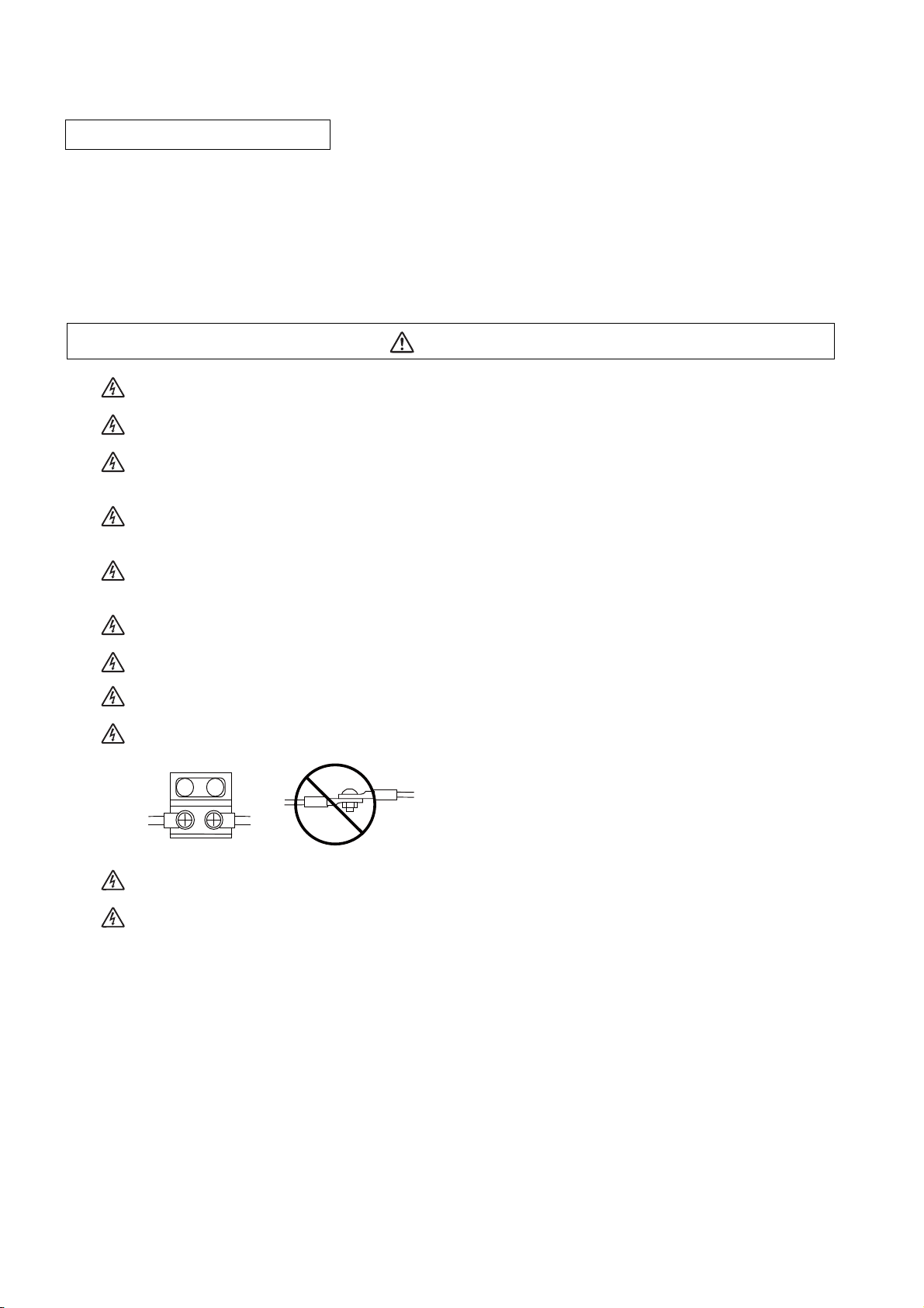
Insulate the power lead using a fixed terminal block. Failure to observe this could result in electric shocks.
Completely turn off the all lines of the power supply externally before wiring.
Not completely turning off all power could result in electric shock or damage to the product.
When turning on the power supply or operating the module after wiring, be sure that the module's terminal
covers are correctly attached.
Not attaching the terminal cover could result in electric shock.
2. Items related to prevention of fire
CAUTION
Install the controller, drive unit, motor and regenerative resistor on non-combustible material. Installation
directly on or near combustible materials could result in fires.
If any malfunction in the unit is observed, shut off the power at the unit’s power supply side. Continuous
flow of large current could result in fires.
Install an appropriate no fuse breaker (NFB) and contactor (MC) on the power input section of the drive unit
and configure the sequence that shuts the power off upon drive unit’s emergency stop or alarm.
When a breaker is shared for multiple power supply units, the breaker may not function upon short-circuit
failure in a small capacity unit. Do not share a breaker for multiple units as this is dangerous.
Incorrect wiring and connections could cause the devices to damage or burn.
3. Items related to prevention of bodily injury or property damage
DANGER
When transporting or installing a built-in IPM spindle or linear servomotor, be careful so that your hand or
property will not be trapped in the motors or other metal objects. Also keep the devices with low magnetic
tolerance away from the product.
CAUTION
Do not apply voltages to the connectors or terminals other than voltages indicated in the connection and
setup manual for the controller or specifications manual for the drive unit. Failure to observe this could
cause bursting, damage, etc.
Incorrect connections could cause the devices to rupture or damage, etc. Always connect the cables to the
indicated connectors or terminals.
Incorrect polarity (+ -) could cause the devices to rupture or damage, etc.
Persons wearing medical devices, such as pacemakers, must stay away from this unit. The
electromagnetic waves could adversely affect the medical devices.
Fins on the rear of the unit, regenerative resistor and motor, etc., will be hot during operation and for a while
after the power has been turned OFF. Do not touch or place the parts and cables, etc. close to these
sections. Failure to observe this could result in burns.
Do not enter the machine’s movable range during automatic operation. Keep your hands, feet or face away
from the spindle during rotation.
4. General precautions
Always follow the precautions below. Incorrect handling could result in faults, injuries or electric shocks, etc.
(1) Items related to product and manual
CAUTION
For items described as "Restrictions" or "Usable State" in this manual, the instruction manual issued by
the machine tool builder takes precedence over this manual.
Items that are not described in this manual must be interpreted as "not possible".
This manual is written on the assumption that all the applicable functions are included.
Some of them, however, may not be available for your NC system.
Refer to the specifications issued by the machine tool builder before use.
Refer to the Instruction Manual issued by each machine tool builder for details on each machine tool.
Some screens and functions may differ depending on each NC system (or version), and some functions
may not be possible. Please confirm the specifications before starting to use.
Refer to "Smart safety observation" (BNP-C3072-022) for details about the connection with safety
observing I/O device.
Do not connect NC system to the Internet-connected network.
To maintain the safety of the NC system against unauthorized access from external devices via the
network, take appropriate measures.
(2) Transportation and installation
CAUTION
Correctly transport the products according to the mass.
Use motor’s suspension bolts to transport the motor itself. Do not use it to transport the motor after
installation onto the machine.
Do not stack the products exceeding the indicated limit.
Do not hold the cables, shaft or detector when transporting the motor.
Do not transport the controller or drive unit by suspending or holding the connected wires or cables.
Do not hold the front cover when transporting the unit, or the front cover could come off, causing the unit
to drop.
Install on a non-combustible place where the unit’s or motor’s mass can be withstood according to the
instruction manual.
The motor does not have a complete water-proof (oil-proof) structure. Do not allow oil or water to contact
or enter the motor. Prevent the cutting chips from being accumulated on the motor as they easily soak up
oil.
When installing the motor facing upwards, take measures on the machine side so that gear oil, etc., will not
enter the motor shaft.
Do not remove the detector from the motor. (The detector installation screw is treated with sealing.)
Do not allow foreign matters, especially, conductive foreign matters such as screws or metal chips, or
combustible foreign matters such as oil, to enter the controller, drive unit or motor. Failure to observe this
could result in rupture or damage.
Do not get on the product or place heavy objects on it.
Provide prescribed distance between the controller/drive unit and inner surface of the control panel/other
devices.
Do not install or operate the controller, drive unit or motor that is damaged or has missing parts.
Take care not to cut hands, etc. with the heat radiating fins or metal edges.
CAUTION
Do not block the intake/outtake ports of the motor with the cooling fan.
Install the controller’s display section and operation board section on the spot where cutting oil will not
reach.
The controller, drive unit and motor are precision devices, so do not drop or apply thumping vibration and
strong impacts on them.
The controller and drive unit are precision devices, so do not drop or apply strong impacts on them.
Store and use the units according to the environment conditions indicated in each specifications manual.
When disinfectants or insecticides must be used to treat wood packaging materials, always use methods
other than fumigation (for example, apply heat treatment at the minimum wood core temperature of 56 °C
for a minimum duration of 30 minutes (ISPM No. 15 (2009))).
If products such as units are directly fumigated or packed with fumigated wooden materials, halogen
substances (including fluorine, chlorine, bromine and iodine) contained in fumes may contribute to the
erosion of the capacitors.
When exporting the products, make sure to comply with the laws and regulations of each country.
Do not use the products in conjunction with any components that contain halogenated flame retardants
(bromine, etc). Failure to observe this may cause the erosion of the capacitors.
Securely fix the motor to the machine. The motor could come off during operation if insecurely fixed.
Always install the motor with reduction gear in the designated direction. Failure to observe this could result
in oil leaks.
Always install a cover, etc., over the shaft so that the rotary section of the motor cannot be touched during
motor rotation.
When installing a coupling to the servomotor shaft end, do not apply impacts by hammering, etc. The
detector could be damaged.
Use a flexible coupling when connecting with a ball screw, etc., and keep the shaft core deviation smaller
than the tolerable radial load of the shaft.
Do not use a rigid coupling as an excessive bending load will be applied on the shaft and could cause the
shaft to break.
Do not apply a load exceeding the tolerable level onto the motor shaft. The shaft or bearing could be
damaged.
Before using this product after a long period of storage, please contact the Mitsubishi Service Station or
Service Center.
Following the UN recommendations, battery units and batteries should be transported based on the
international regulations such as those determined by International Civil Aviation Organization (ICAO),
International Air Transport Association (IATA), International Maritime Organization (IMO) and U.S.
Department of Transportation (DOT).
(3) Items related to wiring
RA
RA
COM COM
Control
output
signal
Drive unit
Control
output
signal
Drive unit
(24VDC) (24VDC)
CAUTION
Correctly wire this product. Failure to observe this could result in motor runaway, etc.
Incorrect terminal connections could cause the devices to rupture or damage, etc.
Do not install a phase advancing capacitor, surge absorber or radio noise filter on the output side of the
drive unit.
Correctly connect the output side (terminal U, V, W). The motor will not run properly if incorrectly
connected.
Always install an AC reactor per each power supply unit.
Always install an appropriate breaker per each power supply unit. A breaker cannot be shared for multiple
power supply units.
Do not directly connect a commercial power supply to the motor. Failure to observe this could result in
faults.
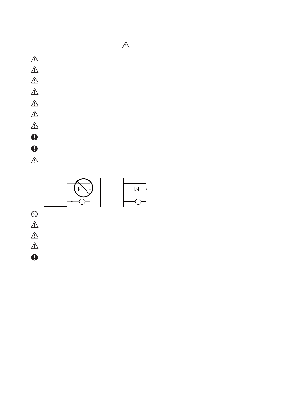
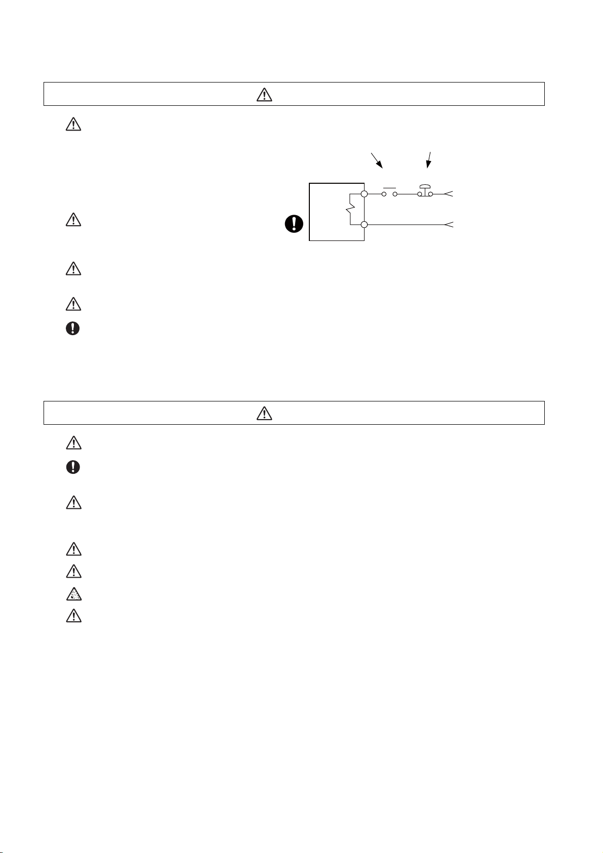
When using an inductive load such as relays, always connect a diode in parallel to the load as a noise
countermeasure.
When using a capacitive load such as a lamp, always connect a protective resistor serially to the load to
suppress rush currents.
Do not mistake the direction of the surge absorption diode to be installed on the DC relay for the control
output signal. If mistaken, the signal will not be output due to fault in the drive unit, and consequently the
protective circuit, such as emergency stop, could be disabled.
Do not connect or disconnect the cables between units while the power is ON.
Do not connect or disconnect the PCBs while the power is ON.
Do not pull the cables when connecting/disconnecting them.
Securely tighten the cable connector fixing screw or fixing mechanism. The motor could come off during
operation if insecurely fixed.
Always treat the shield cables indicated in the Connection Manual with grounding measures such as cable
clamps.
CAUTION
RS-232C
NC unit
Device
Switch
AC socket
Separate the signal wire from the drive line or power line when wiring.
Carry out wiring so that there is no possibility of short circuit between wires, nor of dangerous state.
Use wires and cables whose wire diameter, heat resistance level and bending capacity are compatible with
the system.
Ground the device according to the requirements of the country where the device is to be used.
Wire the heat radiating fins and wires so that they do not contact.
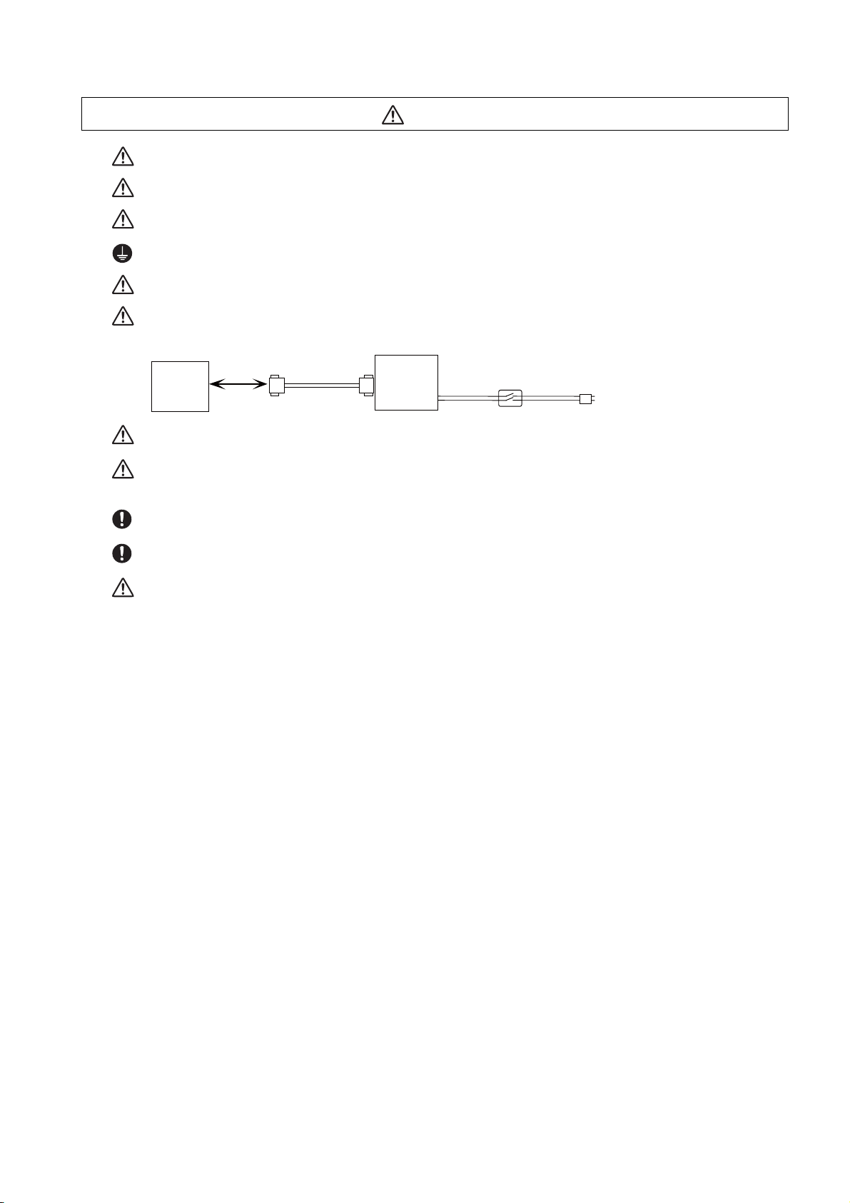
When using the RS-232C device as a peripheral device, caution must be paid for connector connection/
disconnection. Always use a double-OFF type AC power supply switch on the device side, and connect/
disconnect the connector with the AC power supply on the device side OFF.
Using a stabilized power supply without overcurrent protection may cause the unit's failure due to
miswiring of 24V.
12V, 5V, and 3.3V output from connectors are to supply the power for dedicated peripheral devices. Do not
use for other equipment to supply the power since we do not guarantee the NC operation by voltage down
or noise sneaking.
When using an inductive load such as a relay, always connect a diode in parallel to the load to prevent a
counter-electromotive force.
When the rush current exceeds the maximum output current, always connect a protective resistor serially
to the load to suppress rush currents.
The wires from the surge absorber should be connected without extensions.
(4) Set up
WARNING
Do not cancel the emergency stop before confirming the basic operation.
Always set the stroke end and stroke limit. Failure to set this could result in collision with the machine end.
CAUTION
If the descriptions relating to the "restrictions" and "allowable conditions" conflict between this manual
and the machine tool builder's instruction manual. the latter has priority over the former.
The operations to which no reference is made in this manual should be considered "impossible".
This manual is written on the assumption that all the applicable functions are included.
Some of them, however, may not be available for your NC system.
Refer to the specifications issued by the machine tool builder before use.
Some screens and functions may differ depending on each NC system (or version), and some functions
may not be possible. Please confirm the specifications before starting to use.
If the battery low warning is issued, save the machining programs, tool data and parameters in an input/
output device, and then replace the battery. When the battery alarm is issued, the machining programs,
tool data and parameters may have been destroyed. Replace the battery and then reload the data.
Do not adjust the spindle when possible risks associated with adjustment procedures are not thoroughly
taken into consideration.
Be careful when touching spindle's rotating section, or your hand may be caught in or cut.
(5) Operation and Adjustments
CAUTION
If the operation start position is set in a block which is in the middle of the program and the program is
started, the program before the set block is not executed. Please confirm that G and F modal and
coordinate values are appropriate. If there are coordinate system shift commands or M, S, T and B
commands before the block set as the start position, carry out the required commands using the MDI, etc.
If the program is run from the set block without carrying out these operations, there is a danger of
interference with the machine or of machine operation at an unexpected speed, which may result in
breakage of tools or machine tool or may cause damage to the operators.
Under the constant surface speed control (during G96 modal), if the axis targeted for the constant surface
speed control moves toward the spindle center, the spindle rotation speed will increase and may exceed
the allowable speed of the workpiece or chuck, etc. In this case, the workpiece, etc. may jump out during
machining, which may result in breakage of tools or machine tool or may cause damage to the operators.
Check and adjust programs and each parameter before starting operation. Failure to observe this could
result in unpredictable operations depending on the machine.
Do not make drastic adjustments or changes in the parameters as the operation could become unstable.
In the explanation on bits, set all bits not used, including blank bits, to "0".
(6) Usage
CAUTION
Use this product within the range of environmental condition described in this manual.
Using this product in an environment outside the range could result in electric shock, fire, operation failure,
or damage to or deterioration of the product.
Install an external emergency stop circuit so that the operation can be stopped and the power turns OFF
immediately when unforeseen situation occurs. A contactor, etc., is required in addition to the shutoff
function mounted in the controller.
Turn OFF the power immediately if any smoke, abnormal noise or odor is generated from the controller,
drive unit or motor.
Only a qualified technician may disassemble or repair this product.
Do not alter.
Use a noise filter, etc. to reduce the effect of electromagnetic disturbances in the case where
electromagnetic disturbances could adversely affect the electronic devices used near the drive unit.
Use the drive unit, motor and each regenerative resistor with the designated combination. Failure to
observe this could result in fires or faults.
The combination of the motor and drive unit that can be used is determined. Be sure to check the models
of motor and drive unit before test operation.
The brakes (electromagnetic brakes) mounted in the servomotor are used for the purpose of holding, and
must not be used for normal braking. Also, do not run the motor with the motor brake applied. Motor brake
is used for the purpose of holding.
For the system running via a timing belt, install a brake on the machine side so that safety can be ensured.
Be sure to confirm SERVO OFF (or READY OFF) when applying the electromagnetic brake. Also, be sure
to confirm SERVO ON prior to releasing the brake.
When using the DC OFF type electromagnetic brake, be sure to install a surge absorber on the brake
terminal.
Do not connect or disconnect the cannon plug while the electromagnetic brake’s power is ON. The cannon
plug pins could be damaged by sparks.
After changing programs/parameters, or after maintenance/inspection, always carry out a test operation
before starting actual operation.
Use the power that are complied with the power specification conditions (input voltage, input frequency,
tolerable instantaneous power failure time) indicated in each specifications manual.
When making detector cables, do not mistake connection. Failure to observe this could result in
malfunction, runaway or fire.
Surge absorber to be selected varies depending on input power voltage.
(7) Troubleshooting
MBR EMG
Motor
Electromagnetic
brake
Shut off with motor
brake control output
Shut off with CNC brake
control PLC output
24VDC
CAUTION
Use a motor with electromagnetic brakes or
establish an external brake mechanism for
the purpose of holding; this serves as
countermeasures for possible hazardous
situation caused by power failure or
product fault.
Use a double circuit structure for the
electromagnetic brake’s operation circuit
so that the brakes will activate even when
the external emergency stop signal is
issued.
The machine could suddenly restart when the power is restored after an instantaneous power failure, so
stay away from the machine. (Design the machine so that the operator safety can be ensured even if the
machine restarts.)
To secure the absolute position, do not shut off the servo drive unit’s control power supply when its battery
voltage drops (warning 9F) in the servo drive unit side.
If the battery voltage drop warning alarm occurs in the controller side, make sure to back up the machining
programs, tool data and parameters, etc. with the input/output device before replacing the battery.
Depending on the level of voltage drop, memory loss could have happened. In that case, reload all the data
backed up before the alarm occurrence.
(8) Maintenance, inspection and part replacement
CAUTION
Periodically back up the programs, tool data and parameters to avoid potential data loss. Also, back up
those data before maintenance and inspections.
When replacing the battery on the controller side, the machining programs, tool data and parameters
should be backed up with the input/output device beforehand. In case the memory is damaged in replacing
the batteries, reload all the data backed up before replacing the battery.
The electrolytic capacitor’s capacity will drop due to deterioration. To prevent secondary damage due to
capacitor’s faults, Mitsubishi recommends the electrolytic capacitor to be replaced approx. every five
years even when used in a normal environment. Contact the Service Center or Service Station for
replacements.
Do not perform a megger test (insulation resistance measurement) during inspection.
Do not replace parts or devices while the power is ON.
Do not short-circuit, charge, overheat, incinerate or disassemble the battery.
There may be a unit filled with substitute Freon in the heat radiating fins of the 37kW or smaller unit. Be
careful not to break the heat radiating fins during maintenance or replacement.

(9) Disposal
CAUTION
Take the batteries and backlights for LCD, etc., off from the controller, drive unit and motor, and dispose
of them as general industrial wastes.
Do not alter or disassemble controller, drive unit, or motor.
Collect and dispose of the spent batteries and the backlights for LCD according to the local laws.
(10) General precautions
To explain the details, drawings given in the instruction manual, etc., may show the unit with the cover
or safety partition removed. When operating the product, always place the cover or partitions back to
their original position, and operate as indicated in the instruction manual, etc.


Treatment of waste
The following two laws will apply when disposing of this product. Considerations must be made to each law.
The following laws are in effect in Japan. Thus, when using this product overseas, the local laws will have a
priority. If necessary, indicate or notify these laws to the final user of the product.
(1) Requirements for "Law for Promotion of Effective Utilization of Resources"
(a) Recycle as much of this product as possible when finished with use.
(b) When recycling, often parts are sorted into steel scraps and electric parts, etc., and sold to scrap
contractors. Mitsubishi recommends sorting the product and selling the members to appropriate
contractors.
(2) Requirements for "Law for Treatment of Waste and Cleaning"
(a) Mitsubishi recommends recycling and selling the pr oduct when n o longer needed a ccording to item
(1) above. The user should make an effort to reduce waste in this manner.
(b) When disposing a product that cannot be resold, it shall be treated as a waste product.
(c) The treatment of industrial waste must be commissioned to a licensed industrial waste treatment
contractor, and appropriate measures, including a manifest co ntrol, must be taken.
(d) Batteries correspond to "primary batteries", and must be disposed of according to local disposal
laws.


Disposal
(Note) This symbol mark is for EU countries only.
This symbol mark is according to the directive 2006/66/EC Article 20 Information for endusers and Annex II.
Your MITSUBISHI ELECTRIC product is designed and manufactured with high quality materials and
components which can be recycled and/or reused.
This symbol means that batteries and accumulators, at their end-of-life, should be disposed of
separately from your household waste.
If a chemical symbol is printed beneath the symbol shown above, this chemical symbol means that the
battery or accumulator contains a heavy metal at a certain concentration. This will be indicated as
follows:
Hg: mercury (0,0005%), Cd: cadmium (0,002%), Pb: lead (0,004%)
In the European Union there are separate collection systems for used batteries and accumulators.
Please, dispose of batteries and accumulators correctly at your local community waste collection/
recycling centre.
Please, help us to conserve the environment we live in!


Trademarks
MELDAS, MELSEC, EZSocket, EZMotion, iQ Platform, MELSEC iQ-R, MELSOFT, GOT, CC-Link, CC-Link/LT,
CC-Link IE, EcoMonitorLight and SLMP are either trademarks or registered trademarks of Mitsubishi Electric
Corporation in Japan and/or other countries.
Ethernet is a registered trademark of Xerox Corporation in the United States and/or other countries.
Microsoft®, Windows®, SQL Server® and Access® are either trademarks o r registe r ed trademarks of Microsoft
Corporation in the United States and/or other countries.
SD logo and SDHC logo are either registered trademarks or trademarks of LLC.
UNIX is a registered trademark of The Open Group in the United States and/or other countries.
Intel® and Pentium® are either trademarks or registered trademarks of Intel Corporation in the United States and/or
other countries.
MODBUS® is either a trademark or a registered trad emark of Schneider Electric USA, Inc. or the affiliated
companies in Japan and/or other countries.
EtherNet/IP is a trademark of Open DeviceNet Vendor Association,Inc.
PROFIBUS-DP and PROFINET are either trademarks of Profibus International.
Oracle® is a registered trademark of Oracle Corporation, the subsidiaries, or the affiliated companies in the United
States and /or other countries.
VNC is a registered trademark of RealVNC Ltd. in the United States and other countries.
Other company and product names that appear in this manual are trademarks or registered trademarks of the
respective companies.


本製品の取扱いについて
( 日本語 /Japanese)
本製品は工業用 ( クラス A) 電磁環境適合機器です。販売者あるいは使用者はこの点に注意し、住商業環境以外で
の使用をお願いいたします。
Handling of our product
(English)
This is a class A product. In a domestic environment this product may cause radio interference in which case the
user may be required to take adequate measures.
본 제품의 취급에 대해서
( 한국어 /Korean)
이 기기는 업무용 (A 급 ) 전자파적합기기로서 판매자 또는 사용자는 이 점을 주의하시기 바라며 가정외의 지역에
서 사용하는 것을 목적으로 합니다 .


Contents
1 System Basic Configuration ....................................................................................................................... 1
1.1 System Basic Configuration Drawing..................................................................................................... 2
2 General Connection Diagram...................................................................................................................... 3
2.1 General Connection Diagram [M800S] .................................................................................................. 4
2.2 General Connection Diagram [M80] ...................................................................................................... 5
3 List of Configuration.................................................................................................................................... 7
3.1 Control Unit [M800S].............................................................................................................................. 8
3.2 Control Unit [M80] .................................................................................................................................. 8
3.3 Display Unit [M800S] ............................................................................................................................. 8
3.4 Display Unit [M80].................................................................................................................................. 8
3.5 Keyboard Unit [M800S].......................................................................................................................... 9
3.6 Keyboard Unit [M80] .............................................................................................................................. 9
3.7 Operation Panel I/O Unit...................................................................................................................... 10
3.8 Remote I/O Unit ................................................................................................................................... 11
3.9 Function Expansion Unit [M80] ............................................................................................................ 11
3.10 Communication Expansion Unit......................................................................................................... 11
3.11 Manual Pulse Generator .................................................................................................................... 12
3.12 Synchronous Feed Encoder .............................................................................................................. 12
3.13 MITSUBISHI CNC Machine Operation Panel .................................................................................... 12
3.14 Handy Terminal.................................................................................................................................. 12
3.15 Cable Connector Sets........................................................................................................................ 12
3.16 Thermistor Sets.................................................................................................................................. 13
3.17 Genuine Memory Card....................................................................................................................... 13
3.18 Durable Parts ..................................................................................................................................... 13
3.19 Replacements .................................................................................................................................... 13
3.20 List of Cables ..................................................................................................................................... 14
4 General Specifications .............................................................................................................................. 17
4.1 Environment Conditions [M800S] ........................................................................................................ 18
4.1.1 Installation Environment Conditions............................................................................................. 18
4.1.2 24VDC Stabilized Power Supply Selecting Conditions................................................................ 20
4.2 Environment Conditions [M80]............................................................................................................. 21
4.2.1 Installation Environment Conditions............................................................................................. 21
4.2.2 24VDC Stabilized Power Supply Selecting Conditions................................................................ 23
4.3 Control Unit [M800S]............................................................................................................................ 24
4.3.1 FCU8-MU542 / FCU8-MA542 / FCU8-MU541 / FCU8-MA541.................................................... 24
4.4 Control Unit [M80] ................................................................................................................................ 36
4.4.1 FCU8-MU511 / FCU8-MU512 / FCU8-MU501 / FCU8-MU502 ................................................... 36
4.5 Display Unit [M800S] ........................................................................................................................... 39
4.5.1 10.4-type (FCU8-DU141-31)........................................................................................................ 39
4.5.2 15-type (FCU8-DU181-31)........................................................................................................... 41
4.5.3 Precautions.................................................................................................................................. 43
4.6 Display Unit [M80]................................................................................................................................ 44
4.6.1 8.4-type (FCU8-DU121-12).......................................................................................................... 44
4.6.2 10.4-type (FCU8-DU141-32)........................................................................................................ 46
4.6.3 15-type (FCU8-DU181-32)........................................................................................................... 48
4.6.4 Precautions................................................................................................................
4.7 Keyboard Unit ...................................................................................................................................... 51
4.7.1 Keyboard for 8.4-type Display Unit (FCU8-KB026) ..................................................................... 52
4.7.2 Keyboard for 8.4-type Display Unit (FCU8-KB028) ..................................................................... 53
4.7.3 Keyboard for 8.4-type Display Unit (FCU8-KB029) ..................................................................... 54
4.7.4 Keyboard for 10.4-type Display Unit (FCU8-KB041) ................................................................... 55
4.7.5 Keyboard for 10.4-type Display Unit (FCU8-KB046) ................................................................... 56
4.7.6 Keyboard for 10.4-type Display Unit (FCU8-KB047) ................................................................... 57
4.7.7 Keyboard for 10.4-type Display Unit (FCU8-KB048) ................................................................... 58
4.7.8 Keyboard for 15-type Display Unit (FCU8-KB083) ...................................................................... 59
.................. 50

4.8 Operation Panel I/O Unit ...................................................................................................................... 60
4.8.1 List of Units .................................................................................................................................. 60
4.8.2 FCU8-DX750/ FCU8-DX760 / FCU8-DX761 ............................................................................... 61
4.9 Remote I/O Unit ................................................................................................................................... 78
4.9.1 List of Units .................................................................................................................................. 78
4.9.2 FCU8-DX220 / FCU8-DX230 / FCU8-DX231 / FCU8-DX202 / FCU8-DX213 /
FCU8-DX213-1 / FCU8-DX654 / FCU8-DX654-1 / FCU8-DX651/ FCU8-DX408........................ 79
4.10 Function Expansion Unit .................................................................................................................. 113
4.10.1 Functional Safety Expansion Unit (FCU8-EX133) ................................................................... 113
4.11 Communication Expansion Unit ....................................................................................................... 114
4.11.1 CC-Link (FCU8-EX561) ........................................................................................................... 114
4.11.2 PROFIBUS-DP (FCU8-EX563)................................................................................................ 117
4.11.3 EtherNet/IP (FCU8-EX565)...................................................................................................... 120
4.11.4 Option Relay Unit (FCU8-EX702) ............................................................................................ 123
4.11.5 Option Relay Unit (FCU8-EX703) ............................................................................................ 124
4.12 Manual Pulse Generator .................................................................................................................. 125
4.12.1 5V Manual Pulse Generator (UFO-01-2Z9) ............................................................................. 125
4.12.2 Manual Pulse Generator (HD60C).......................................................................................... 126
4.13 Synchronous Feed Encoder............................................................................................................. 127
4.13.1 Synchronous Feed Encoder (OSE-1024-3-15-68)................................................................... 127
4.14 MITSUBISHI CNC Machine Operation Panel .................................................................................. 129
4.14.1 Main Panel A , B (FCU8-KB921 / FCU8-KB922 , FCU8-KB923 / FCU8-KB924) .................... 129
4.14.2 Sub Panel A (FCU8-KB931) .................................................................................................... 135
4.15 Handy Terminal................................................................................................................................ 140
4.16 Thermistor........................................................................................................................................ 144
4.16.1 Thermistor(PT3C-51F-M2)....................................................................................................... 144
4.17 Exclusive SD Cards for MITSUBISHI CNC...................................................................................... 145
4.18 Specifications and Precautions of USB/SD/LAN Interface .............................................................. 146
4.18.1 USB Interface (Memory I/F card) ............................................................................................. 146
4.18.2 SD Interface (Memory I/F card) ............................................................................................... 147
4.18.3 LAN Interface (Control Unit)..................................................................................................... 147
5 Installation ................................................................................................................................................ 149
5.1 Heat Radiation Countermeasures...................................................................................................... 150
5.2 Noise Countermeasures .................................................................................................................... 153
5.2.1 Connection of Frame Ground (FG) ............................................................................................ 153
5.2.2 Shield Clamping of Cables......................................................................................................... 154
5.2.3 Connecting Spark Killers............................................................................................................ 155
5.2.4 Lightning Surge Protection Countermeasure............................................................................. 156
5.3 Unit Installation................................................................................................................................... 157
5.3.1 Display Unit................................................................................................................................ 157
5.3.2 Keyboard Unit ............................................................................................................................ 160
5.3.3 Operation Panel I/O Unit............................................................................................................ 166
5.3.4 Remote I/O Unit ......................................................................................................................... 167
5.3.5 Functional Safety Expansion Unit .............................................................................................. 169
5.3.6 Communication Expansion Unit................................................................................................. 170
5.3.7 MITSUBISHI CNC Machine Operation Panel .......
6 Precautions for Connecting .................................................................................................................... 175
6.1 Precautions for Wiring........................................................................................................................ 176
6.1.1 Precautions when Connecting/Disconnecting Cables ............................................................... 176
6.1.2 Precautions for Using Optical Communication Cable ................................................................ 179
6.1.3 Precautions for Connecting 24V Power Supply ......................................................................... 180
6.2 Turning the Power ON/OFF ............................................................................................................... 181
7 Connection of Control Unit ..................................................................................................................... 183
7.1 Control Unit Connection System Drawing.......................................................................................... 184
7.2 Connecting with Power Supply .......................................................................................................... 185
7.3 Connecting with Emergency Stop Signal........................................................................................... 186
7.4 Connecting with Operation Panel I/O Unit ......................................................................................... 188
7.5 Connecting with Remote I/O Unit....................................................................................................... 189
..................................................................... 172

7.6 Connecting with Drive Unit................................................................................................................. 190
7.6.1 Connecting with Drive Unit MDS-E/EH Series........................................................................... 191
7.6.2 Connecting with Drive Unit MDS-EM/EMH Series..................................................................... 193
7.6.3 Connecting with Drive Unit MDS-EJ/EJH Series ....................................................................... 195
7.7 Connecting with RS-232C Device...................................................................................................... 196
7.8 Connecting with Skip Signal (Sensor)................................................................................................ 197
7.9 Connecting with Manual Pulse Generator ......................................................................................... 199
7.9.1 Handle Numbers ........................................................................................................................ 200
7.10 Connecting with Synchronous Feed Encoder.................................................................................. 201
7.11 Connecting I/O Device via Communication Expansion Unit ............................................................ 202
7.11.1 Connecting I/O Device via CC-Link ......................................................................................... 203
7.11.2 Connecting I/O Device via PROFIBUS-DP.............................................................................. 206
7.11.3 Connecting I/O Device via EtherNet/IP....................................................................................207
8 Connection of Keyboard Unit ................................................................................................................. 209
8.1 Keyboard Unit Connection System Drawing ...................................................................................... 210
8.2 Connecting with Operation Panel I/O Unit ......................................................................................... 210
9 Connection of Operation Panel I/O Unit................................................................................................. 211
9.1 Operation Panel I/O Unit Connection System Drawing ..................................................................... 212
9.2 Connecting with Frame Ground ......................................................................................................... 213
9.3 Connecting with Control Unit ............................................................................................................. 214
9.4 Connecting with Keyboard Unit.......................................................................................................... 214
9.5 Connecting with Remote I/O Unit....................................................................................................... 215
9.6 Connecting with Manual Pulse Generator (MPG).............................................................................. 216
9.6.1 Handle Numbers ........................................................................................................................ 218
9.7 Connecting with Machine Operation Panel........................................................................................ 219
9.7.1 Wiring for 24V Common Input.................................................................................................... 220
9.7.2 Wiring for 0V Common Input...................................................................................................... 221
9.7.3 Wiring for Source Type Output .................................................................................................. 222
9.7.4 Example of Wiring CJ42 (FCU8-DX760) ................................................................................... 223
9.8 Connecting with Analog I/O Signal (FCU8-DX761) ........................................................................... 224
10 Connection of Remote I/O Unit ............................................................................................................. 225
10.1 Remote I/O Unit Connection System Drawing................................................................................. 226
10.2 Connecting with Power Supply ........................................................................................................ 227
10.3 Connecting with Frame Ground ....................................................................................................... 229
10.4 Connecting with Control Unit ........................................................................................................... 230
10.5 Connecting with Operation Panel I/O Unit ....................................................................................... 231
10.6 Connecting with Machine Control Signal
(FCU8-DX220 / FCU8-DX230 / FCU8-DX231 / FCU8-DX651) ....................................................... 232
10.7 Connecting with Machine Control Signal
(FCU8-DX213 / FCU8-DX213-1 / FCU8-DX654 / FCU8-DX654-1) ................................................. 237
10.8 Connecting with Safety Machine Control Signal (FCU8-DX651) ..................................................... 245
10.9 Connecting with Analog I/O Signal (FCU8-DX202) ......................................................................... 247
10.10 Connecting with Thermistor (FCU8-DX408) .................................................................................. 249
11 Connection of Manual Pulse Generator............................................................................................... 253
11.1 Manual Pulse Generator Connection System Drawing.................................................................... 254
11.2 Connecting with Control Unit ........................................................................................................... 255
11.3 Connecting with Operation Panel I/O Unit ..................................................................................
12 Connection of
12.1 Synchronous Feed Encoder Connection System Drawing .............................................................. 258
12.2 Connecting with Control Unit ........................................................................................................... 258
13 Connection of MITSUBISHI CNC Machine Operation Panel .............................................................. 259
13.1 Machine Operation Panel Connection System Drawing .................................................................. 260
13.2 Connecting with Power Supply ........................................................................................................ 261
13.3 Connecting with Frame Ground ....................................................................................................... 262
Synchronous Feed Encoder ........................................................................................ 257
..... 255

13.4 Connecting with Operation Panel I/O Unit ....................................................................................... 262
13.5 Connecting Emergency Stop Switch................................................................................................ 263
13.6 Connecting with Sub Panel.............................................................................................................. 263
13.7 Software Interface............................................................................................................................ 266
14 Connection of Handy Terminal ............................................................................................................. 271
14.1 Handy Terminal Connection System Drawing ................................................................................. 272
14.2 Connecting with Control Unit............................................................................................................ 272
15 Cable ....................................................................................................................................................... 273
15.1 Symbols for Writing Cable Drawings................................................................................................ 274
15.2 Cable Relating to NC ....................................................................................................................... 275
15.2.1 FCUA-R050/R054 Cable ......................................................................................................... 275
15.2.2 G071 Cable.............................................................................................................................. 276
15.2.3 G123 Cable.............................................................................................................................. 277
15.2.4 G430 Cable.............................................................................................................................. 278
15.2.5 G460 Cable.............................................................................................................................. 279
15.2.6 J010 Cable............................................................................................................................... 280
15.2.7 J020/J021/J022 Cable ............................................................................................................. 281
15.2.8 J023/J024/J025 Cable ............................................................................................................. 282
15.2.9 J026/J027 Cable ...................................................................................................................... 283
15.2.10 J030/J031 Cable .................................................................................................................... 284
15.2.11 J070/J071 Cable .................................................................................................................... 285
15.2.12 J100 Cable............................................................................................................................. 286
15.2.13 J120 Cable............................................................................................................................. 287
15.2.14 J121 Cable............................................................................................................................. 288
15.2.15 J210 Cable............................................................................................................................. 289
15.2.16 J221 Cable............................................................................................................................. 290
15.2.17 J224 Cable............................................................................................................................. 291
15.2.18 J303 Cable............................................................................................................................. 292
15.2.19 J350 Cable............................................................................................................................. 293
15.2.20 J351 Cable............................................................................................................................. 294
15.2.21 J460 Cable............................................................................................................................. 295
15.2.22 J461 Cable............................................................................................................................. 296
15.2.23 R2-TM Terminator Connector ................................................................................................ 297
15.3 Cable Relating to Drive Unit............................................................................................................. 298
15.3.1 Cable Wire and Assembly........................................................................................................ 298
15.3.2 CNP2E-1 Cable ....................................................................................................................... 299
15.3.3 CNP3EZ-2P/CNP3EZ-3P Cable .............................................................................................. 300
15.3.4 CNV2E-8P/CNV2E-9P Cable .................................................................................................. 301
15.3.5 CNV2E-D Cable....................................................................................................................... 302
15.3.6 CNV2E-HP Cable .................................................................................................................... 303
15.3.7 DG30 Cable ............................................................................................................................. 304
15.3.8 G380 Cable.............................................................................................................................. 305
15.3.9 J395 Cable.................................................................................................................
15.3.10 J396 Cable............................................................................................................................. 307
15.3.11 MR-BKS1CBL-A1-H / MR-BKS1CBL-A2-H Cable ................................................................. 308
15.3.12 MR-BT6V2CBL Cable............................................................................................................ 308
15.3.13 MR-D05UDL3M-B Cable ....................................................................................................... 309
15.3.14 MR-PWS1CBL-A1-H / MR-PWS1CBL-A2-H Cable ............................................................... 309
15.3.15 SH21 Cable............................................................................................................................ 310
15.4 List of Cable Connector Sets ........................................................................................................... 311
.............. 306
16 Setup Outline.......................................................................................................................................... 313
16.1 Hardware Configuration ................................................................................................................... 314
16.2 Flow of Initial Setup.......................................................................................................................... 316
17 Setting the Hardware ............................................................................................................................. 317
17.1 Setting Drive Unit MDS-E/EH Series ............................................................................................... 318
17.1.1 Setting the Rotary Switch......................................................................................................... 318

17.1.2 Setting DIP Switch ................................................................................................................... 319
17.2 Setting Drive Unit MDS-EM/EMH Series ......................................................................................... 320
17.2.1 Setting the Rotary Switch......................................................................................................... 320
17.3 Setting Drive Unit MDS-EJ/EJH Series............................................................................................ 321
17.3.1 Setting the Rotary Switch......................................................................................................... 321
17.3.2 Setting the DIP Switch ............................................................................................................. 322
17.4 Setting Up without Connecting to the Motor/Drive Units at the Startup of Drive Unit ...................... 323
17.5 Connecting the Batteries.................................................................................................................. 324
17.5.1 Control Unit Battery.................................................................................................................. 324
17.5.2 Servo Drive Unit Battery .......................................................................................................... 326
17.6 Connecting and Setting the Remote I/O Unit ................................................................................... 329
17.6.1 Outline of the Remote I/O Unit................................................................................................. 329
17.6.2 Connection and Station No. Setting on Remote I/O Unit ......................................................... 331
17.6.3 Station No. Setting when Using Multiple Remote I/O Units ..................................................... 334
17.6.4 PLC Device Assignment of Digital Signal (DI/DO)................................................................... 337
17.6.4.1 Fixed Device Assignment ................................................................................................338
17.6.4.2 Arbitrary Device Assignment ........................................................................................... 339
17.6.5 Thermistor Input Interface........................................................................................................ 343
17.7 Initializing the NC Internal Data (SRAM).......................................................................................... 344
18 Setting Up with M80/M800S SETUP INSTALLER ................................................................................ 347
18.1 Activate M80/M800S SETUP INSTALLER ...................................................................................... 349
18.2 Install Custom Screen...................................................................................................................... 351
18.3 Install Start-up Screen ..................................................................................................................... 352
18.4 Install APLC C Language Module.................................................................................................... 353
18.5 Install User Cycle ............................................................................................................................. 354
19 Setting the Parameters and Date/Time ................................................................................................ 355
19.1 Selecting the NC System Type and Displayed Language ............................................................... 356
19.2 Setting the Parameters for the System Specifications ..................................................................... 357
19.3 Setting the Parameters for the Machine Specifications ................................................................... 358
19.4 Setting Date and Time ..................................................................................................................... 360
20 PLC Program Writing............................................................................................................................. 361
20.1 Writing PLC Program using the SD Card......................................................................................... 362
20.2 Setting the Ethernet Communication ............................................................................................... 362
20.2.1 Confirming the IP Address for CNC ......................................................................................... 362
20.2.2 Setting the IP Address for PC Side.......................................................................................... 362
20.3 Connecting the Control Unit and a Personal Computer ................................................................... 364
20.4 Setting the Communication with GX Developer............................................................................... 365
20.5 Setting the Parameters on GX Developer........................................................................................ 366
20.5.1 Parameter Setting Screen........................................................................................................ 366
20.5.2 Setting the Number of Device Points ....................................................................................... 367
20.5.3 Setting the Number of Common Pointer Points ....................................................................... 368
20.5.4 Setting the Program Execution Order ......................................................................................369
20.6 Writing a PLC Program with GX Developer ..................................................................................... 370
20.7 Writing a PLC Program to ROM with GX Developer........................................................................ 371
20.8 Setting the PLC Parameters ................................................................................................
Confirming the Basic Operation........................................................................................................... 373
21
21.1 Checking Inputs/Outputs and Alarms .............................................................................................. 374
21.2 Confirming Manual Operation .......................................................................................................... 375
21.2.1 Using the Manual Pulse Generator.......................................................................................... 375
21.2.2 Using JOG Feed ...................................................................................................................... 375
21.3 Servo Simplified Adjustment ............................................................................................................ 376
21.3.1 First Measure Against Vibration............................................................................................... 376
21.3.2 NC Analyzer2........................................................................................................................... 377
............ 372
22 Setting the Position Detection System ................................................................................................ 379
22.1 Adjusting the Absolute Position Detection System .......................................................................... 380

22.1.1 Basic Position Alignment Method I .......................................................................................... 381
22.1.2 Basic Position Alignment Method II ......................................................................................... 384
22.1.3 Machine End Stopper Method: Automatic Initialization............................................................ 386
22.1.4 Machine End Stopper Method: Manual Initialization................................................................ 390
22.1.5 Dog-type .................................................................................................................................. 393
22.1.6 Setting the Grid Interval and the Reference Encoder for Grid Interval .................................... 394
22.1.7 Precautions Common for the Initilization Operation................................................................. 394
22.1.8 Precautions Common for the Dogless-type Absolute Position Detector .................................. 395
22.2 Adjustment of Reference Position Return in Relative Position Detection System ........................... 396
22.2.1 Dog-type Reference Position Return Operation ..................................................................... 396
22.2.2 Dog-type Reference Position Return Adjustment Procedures................................................. 397
23 Setting the Tool Entry Prohibited Range ........................................................................................... 403
23.1 Stroke End (H/W OT)....................................................................................................................... 404
23.2 Stored Stroke Limit (S/W OT) .......................................................................................................... 405
23.2.1 Outline...................................................................................................................................... 405
23.2.2 Stored Stroke Limit I ................................................................................................................ 408
23.2.3 Stored Stroke Limit II ............................................................................................................... 409
23.2.4 Stored Stroke Limit IB .............................................................................................................. 411
23.2.5 Stored Stroke Limit IC.............................................................................................................. 412
23.2.6 Movable Range during Inclined Axis Control ........................................................................... 413
23.2.7 Stored Stroke Limit for Rotation Axis ....................................................................................... 414
23.2.8 Changing the Area for the Stored Stroke Limit I ...................................................................... 414
23.2.9 Precautions .............................................................................................................................. 415
24 Confirming the Spindle Operation........................................................................................................ 417
24.1 In Manual Operation (with Manual Numerical Command) ............................................................... 418
24.2 In MDI Operation.............................................................................................................................. 419
24.3 Confirming the Rotation Speed........................................................................................................ 419
25 Setting the Handy Terminal................................................................................................................... 421
25.1 Inputting the Data from a Personal Computer.................................................................................. 422
25.2 Inputting the Data from NC .............................................................................................................. 425
26 Setting the Deceleration Check ............................................................................................................ 427
26.1 Function ........................................................................................................................................... 428
26.2 Deceleration Check Method............................................................................................................. 430
26.3 Deceleration Check for Opposite Direction Movement Reversal ..................................................... 432
26.4 Parameter ........................................................................................................................................ 433
26.5 Relation with Other Functions .......................................................................................................... 435
26.6 Precautions ...................................................................................................................................... 436
27 Adjust S-analog Screen......................................................................................................................... 437
27.1 Adjustment Preparations.................................................................................................................. 439
27.2 Performing Automatic Adjustments.................................................................................................. 439
27.3 Performing Manual Adjustments..............................................................................................
28 Device Open Parameter Screen............................................................................................................ 443
........ 440
29 SRAM Open Parameter Screen............................................................................................................. 449
30 Data Backup and Restoration ............................................................................................................... 455
30.1 All Backup ........................................................................................................................................ 457
30.2 All Restoration.................................................................................................................................. 459
31 Appx.1: Setting the System Lock ......................................................................................................... 461
31.1 Setting the Encryption Key............................................................................................................... 462
31.2 Setting of Expiration Date ................................................................................................................ 463
31.3 Display of Time Limit Warning and Alarm Notification ..................................................................... 464
31.4 Caution............................................................................................................................................. 464

32 Appx.2: Protection Setting .................................................................................................................... 465
32.1 Protect Setting Screen ..................................................................................................................... 466
32.2 Returning the Password to the Non-input State (Operation level 0 to 3) ......................................... 469
32.3 Changing the Operation Level to One of 4 to 6 ............................................................................... 469
32.4 Changing the Password................................................................................................................... 470
32.5 Clearing the Password..................................................................................................................... 471
32.6 Changing the Protection Level......................................................................................................... 472
32.7 Saving the Protection Level Setting ................................................................................................. 472
33 Appx.3: Displaying Original Logo On Standard Screen..................................................................... 473
34 Appx.4: EMC Installation Guidelines.................................................................................................... 475
34.1 Introduction ...................................................................................................................................... 476
34.2 EMC Directives ................................................................................................................................ 476
34.3 EMC Measures ................................................................................................................................ 477
34.4 Panel Structure ................................................................................................................................ 477
34.4.1 Measures for Control Panel Body ............................................................................................ 477
34.4.2 Measures for Door ................................................................................................................... 478
34.4.3 Measures for Power Supply..................................................................................................... 478
34.5 Measures for Wiring in Panel........................................................................................................... 479
34.5.1 Precautions for Wiring in Panel................................................................................................ 479
34.5.2 Shield Treatment of Cables ..................................................................................................... 480
34.6 EMC Countermeasure Parts............................................................................................................ 481
34.6.1 Shield Clamp Fitting................................................................................................................. 481
34.6.2 Ferrite Core.............................................................................................................................. 482
34.6.3 Surge Absorber........................................................................................................................ 483
34.6.4 Selection of Stabilized Power Supply ...................................................................................... 485
35 Appx.5: Restrictions for Lithium Batteries.......................................................................................... 487
35.1 Restriction for Packing ..................................................................................................................... 488
35.1.1 Target Products ....................................................................................................................... 488
35.1.2 Handling by User ..................................................................................................................... 489
35.1.3 Reference ................................................................................................................................ 489
35.2 Products Information Data Sheet (ER Battery) ................................................................................ 490
35.3 Forbiddance of Transporting Lithium Battery
by Passenger Aircraft Provided in the Code of Federal Regulation................................................. 492
35.4 California Code of Regulation "Best Management Practices for Perchlorate Materials" ................. 492
35.5 Restriction Related to EU Battery Directive ..................................................................................... 493
35.5.1 Important Notes ....................................................................................................................... 493
35.5.2 Information for End-user .......................................................................................................... 493
36 Appx.6: Precautions for Compliance to UL/c-UL Standards ............................................................. 495


1
IB-1501269-F
1
System Basic Configuration

M800S/M80 Series Connection and Setup Manual
1 System Basic Configuration
1.1 System Basic Configuration Drawing
(Control unit is added onto
back of display unit.)
Motor group
Servo/Spindle
drive unit
Manual pulse generator
Manual pulse penerator
Remote I/O unit
Remote I/O unit
Display unit
Operation panel I/O unit
Control unit
(Operation panel I/O unit is added
onto back of keyboard unit.)
Keyboard unit
Synchronous
feed encoder
(Note) For the drive unit configuration, refer to the Instruction Manual of the drive unit you use.
IB-1501269-F
2

3
IB-1501269-F
2
General Connection Diagram

M800S/M80 Series Connection and Setup Manual
2 General Connection Diagram
J395/J396/G380
FCUA-R050/054
1ch
ENC
Field Network
J026(1ch)
J027(2ch)
L1 L2
L3
Skip signal inputs
D-AL
MC
DCOUT
FG
ACIN
CP/NFB
MC
ON OFF
MC
MC
CP/NFB
FG
Max. 8 points
EMG
J120
J303
J070/071
J303
J100
1ch: J030
2ch: J031
EMG
LAN1
SKIP
DCIN
SIO
LAN2
FCU8-EX56x
FCU8-EX70x
FRONT
RIO2ENC CJ71
BL
< J09x>
RIO1
USB_F
SDC_F
USB_B
SDC_B
< J08x>
TP
< J421>
NCKB
3ch
J010
CJ71
<G402>
J210
RIO3EXT
MPG
J070/071
J070/071
5V : J023(1ch)/024(2ch)/025(3ch)
12V : J020(1ch)/021(2ch)/022(3ch)
FCU8-KB04x
FCU8-KB083
FCU8-DX750/DX760/DX761
DI : CJ37/39
DO : CJ38/40
J460/461
J350/351
J210
J210
LCD
MENUKEY
DI:CJ31/33
DO:CJ32/34
RIO1
DCIN
RIO2
J350/351
J350/351
J070/071
DI:CJ31/33
DO:CJ32/34
RIO1
DCIN
RIO2
DI:CJ31/33
DO:CJ32/34
RIO1
DCIN
RIO2
J350/351
J350/351
J070/071
DI:CJ31/33
DO:CJ32/34
RIO1
DCIN
RIO2
DI:CJ31/33
DO:CJ32/34
RIO1
DCIN
RIO2
J350/351
J350/351
(R2-TM)
(R2-TM)
(R2-TM)
G430
(Note 1)
Drive unit
Control unit
Synchronous feed encoder
No-fuse breaker
(NFB)
AC reactor
Circuit protector (CP)
Ethernet device
Ethernet device
24VDC
RS-232C
device
Communication
expansion unit
Menu key
Display unit
Memory mediums
Front memory I/F card
Operation panel I/O unit
Machine
control
relay/contact
Remote I/O unit
24VDC
Remote I/O unit
24VDC
Remote I/O unit
24VDC
Remote I/O unit
24VDC
Remote I/O unit
24VDC
Keyboard unit
To the next remote I/O
or terminator connector
Machine operation
panel made by the
machine tool builder
Skip signal input
24VDC stabilized
power supply
To the next remote I/O
or terminator connector
To the next remote I/O
or terminator connector
Manual pulse
generator (5V/12V)
Manual pulse
generator (5V)
Dotted lines indicate the sections prepared by the machine tool builder.
<> Angle brackets indicates attached cable of unit.
Option
Relay Unit
Machine
control
relay/contact
Machine
control
relay/contact
Handy terminal
FCU8-DX2xx/DX6xx
/DX4xx
OPTH1 OPTH2
J395/J396/G380
FCU8-MU54x/FCU8-MA54x
10.4-type:FCU8-DU141-31
15-type:FCU8-DU181-31
Add-on
CPU card
Drive unit
2.1 General Connection Diagram [M800S]
(Note 1) For information on how to connect the drive unit, refer to the drive unit's manual.
(Note 2) For the connection of MITSUBISHI CNC machine operation panel, refer to the chapter "Connection of
MITSUBISHI CNC Machine Operation Panel".
IB-1501269-F
4

M800S/M80 Series Connection and Setup Manual
2 General Connection Diagram
J395/J396/G380
FCUA-R050/054
1ch
ENC
Field Network
J026(1ch)
J027(2ch)
L1 L2
L3
Skip signal inputs
D-AL
MC
DCOUT
FG
ACIN
CP/NFB
MC
ON OFF
MC
MC
CP/NFB
FG
Max. 8 points
EMG
J120
J303
J070/071
J303
J100
1ch: J030
2ch: J031
EMG
LAN1
SKIP
DCIN
SIO
LAN2
FCU8-EX56x
FCU8-EX70x
FRONT
RIO2ENC CJ71
BL
< J09x>
RIO1
USB_F
SDC_F
USB_B
SDC_B
< J08x>
TP
< J421>
NCKB
3ch
J010
CJ71
<G402>
J210
RIO3EXT
MPG
J070/071
J070/071
5V : J023(1ch)/024(2ch)/025(3ch)
12V : J020(1ch)/021(2ch)/022(3ch)
FCU8-KB04x
FCU8-KB083
FCU8-DX750/DX760/DX761
DI : CJ37/39
DO : CJ38/40
J460/461
J350/351
J210
J210
LCD
MENUKEY
DI:CJ31/33
DO:CJ32/34
RIO1
DCIN
RIO2
J350/351
J350/351
J070/071
DI:CJ31/33
DO:CJ32/34
RIO1
DCIN
RIO2
DI:CJ31/33
DO:CJ32/34
RIO1
DCIN
RIO2
J350/351
J350/351
J070/071
DI:CJ31/33
DO:CJ32/34
RIO1
DCIN
RIO2
DI:CJ31/33
DO:CJ32/34
RIO1
DCIN
RIO2
J350/351
J350/351
(R2-TM)
(R2-TM)
(R2-TM)
G430
(Note 1)
Drive unit
Control unit
Synchronous feed encoder
No-fuse breaker
(NFB)
AC reactor
Circuit protector (CP)
Ethernet device
Ethernet device
24VDC
RS-232C
device
Communication
expansion unit
Menu key
Display unit
Memory mediums
Front memory I/F card
Operation panel I/O unit
Machine
control
relay/contact
Remote I/O unit
24VDC
Remote I/O unit
24VDC
Remote I/O unit
24VDC
Remote I/O unit
24VDC
Remote I/O unit
24VDC
Keyboard unit
To the next remote I/O
or terminator connector
Machine operation
panel made by the
machine tool builder
Skip signal input
24VDC stabilized
power supply
To the next remote I/O
or terminator connector
To the next remote I/O
or terminator connector
Manual pulse
generator (5V/12V)
Manual pulse
generator (5V)
Dotted lines indicate the sections prepared by the machine tool builder.
<> Angle brackets indicates attached cable of unit.
Option
Relay Unit
Machine
control
relay/contact
Machine
control
relay/contact
Handy terminal
FCU8-KB02x
OPTH1
FCU8-MU5x1/FCU8-MU5x2
FCU8-DX2xx/
DX4xx
8.4-type:FCU8-DU121-12
10.4-type:FCU8-DU141-32
15-type:FCU8-DU181-32
(Note 2)
2.2 General Connection Diagram [M80]
(1) Without smart safety observation
(Note 1) For information on how to connect the drive unit, refer to the drive unit's manual.
(Note 2) For the 8.4-type display unit, TP connector is not used.
(Note 3) For the connection of MITSUBISHI CNC machine operation panel, refer to the chapter "Connection of
MITSUBISHI CNC Machine Operation Panel".
5
IB-1501269-F

M800S/M80 Series Connection and Setup Manual
2 General Connection Diagram
J395/J396/G380
FCUA-R050/054
1ch
ENC
Field Network
J026(1ch)
J027(2ch)
L1 L2
L3
Skip signal inputs
D-AL
MC
DCOUT
FG
ACIN
CP/NFB
MC
ON OFF
MC
MC
CP/NFB
FG
Max. 8 points
EMG
J120
J303
J070/071
J303
J100
1ch: J030
2ch: J031
EMG
LAN1
SKIP
DCIN
SIO
LAN2
FCU8-EX56x
FCU8-EX70x
FRONT
RIO2ENC CJ71
BL
< J09x>
RIO1
USB_F
SDC_F
USB_B
SDC_B
< J08x>
TP
< J421>
NCKB
3ch
J010
CJ71
<G402>
J210
RIO3EXT
MPG
J070/071
J070/071
5V : J023(1ch)/024(2ch)/025(3ch)
12V : J020(1ch)/021(2ch)/022(3ch)
FCU8-KB04x
FCU8-KB083
FCU8-DX750/DX760/DX761
DI : CJ37/39
DO : CJ38/40
J460/461
J350/351
J210
J210
LCD
MENUKEY
DI:CJ31/33
DO:CJ32/34
RIO1
DCIN
RIO2
J350/351
J350/351
J070/071
DI:CJ31/33
DO:CJ32/34
RIO1
DCIN
RIO2
DI:CJ31/33
DO:CJ32/34
RIO1
DCIN
RIO2
J350/351
J350/351
J070/071
DI:CJ31/33
DO:CJ32/34
RIO1
DCIN
RIO2
DI:CJ31/33
DO:CJ32/34
RIO1
DCIN
RIO2
J350/351
J350/351
(R2-TM)
(R2-TM)
(R2-TM)
G430
(Note 1)
Drive unit
Control unit
Synchronous feed encoder
No-fuse breaker
(NFB)
AC reactor
Circuit protector (CP)
Ethernet device
Ethernet device
24VDC
RS-232C
device
Communication
expansion unit
Menu key
Display unit
Memory mediums
Front memory I/F card
Operation panel I/O unit
Machine
control
relay/contact
Remote I/O unit
24VDC
Remote I/O unit
24VDC
Remote I/O unit
24VDC
Remote I/O unit
24VDC
Remote I/O unit
24VDC
Keyboard unit
To the next remote I/O
or terminator connector
Machine operation
panel made by the
machine tool builder
Skip signal input
24VDC stabilized
power supply
To the next remote I/O
or terminator connector
To the next remote I/O
or terminator connector
Manual pulse
generator (5V/12V)
Manual pulse
generator (5V)
Dotted lines indicate the sections prepared by the machine tool builder.
<> Angle brackets indicates attached cable of unit.
Option
Relay Unit
Machine
control
relay/contact
Machine
control
relay/contact
Handy terminal
FCU8-DX2xx/DX6xx
/DX4xx
FCU8-KB02x
OPTH1
FCU8-MU511/FCU8-MU512
FCU8-EX133
8.4-type:FCU8-DU121-12
10.4-type:FCU8-DU141-32
15-type:FCU8-DU181-32
(Note 2)
Functional
safety
expansion unit
(Note 3)
(2) With smart safety observation
(Note 1) For information on how to connect the drive unit, refer to the drive unit's manual.
(Note 2) For the 8.4-type display unit, TP connector is not used.
(Note 3) The safety remote I/O unit is available only when the functional safety expansion unit is mounted.
(Note 4) For the connection of MITSUBISHI CNC machine operation panel, refer to the chapter "Connection of
MITSUBISHI CNC Machine Operation Panel".
IB-1501269-F
6

7
IB-1501269-F
3
List of Configuration

M800S/M80 Series Connection and Setup Manual
3 List of Configuration
3.1 Control Unit [M800S]
NC functions
and display controller
For M830S
NC functions
and display controller
For M850S
NC functions
and display controller
For M830S
NC functions
and display controller
For M850S
Classification Type Components Remarks
FCU8-MU542
FCU8-MA542
FCU8-MU541
FCU8-MA541
3.2 Control Unit [M80]
NC functions
and display controller
For M80 Type B
NC functions
and display controller
For M80 Type A
NC functions
and display controller
For M80 Type B
NC functions
and display controller
For M80 Type A
Classification Type Components Remarks
FCU8-MU511
FCU8-MU512
FCU8-MU501
FCU8-MU502
Base control card
Add-on CPU card
Front-side memory I/F card
Base control card
Add-on CPU card
Front-side memory I/F card
Base control card
Add-on CPU card
Front-side memory I/F card
Base control card
Add-on CPU card
Front-side memory I/F card
Base control card
Front-side memory I/F card
Base control card
Front-side memory I/F card
Base control card
Front-side memory I/F card
Base control card
Front-side memory I/F card
Export Trade Control Order noncompliant unit and
Foreign Exchange Order noncompliant unit
Export Trade Control Order noncompliant unit and
Foreign Exchange Order compliant unit
Export Trade Control Order noncompliant unit and
Foreign Exchange Order noncompliant unit
Export Trade Control Order noncompliant unit and
Foreign Exchange Order compliant unit
Export Trade Control Order noncompliant unit and
Foreign Exchange Order noncompliant unit
Export Trade Control Order noncompliant unit and
Foreign Exchange Order noncompliant unit
Export Trade Control Order noncompliant unit and
Foreign Exchange Order noncompliant unit
Export Trade Control Order noncompliant unit and
Foreign Exchange Order noncompliant unit
3.3 Display Unit [M800S]
Classification Type Components Remarks
10.4-type color TFT touch panel
(VGA:640*480)
15-type color TFT touch panel
(XGA:1024*768)
FCU8-DU141-31
FCU8-DU181-31
3.4 Display Unit [M80]
Classification Type Components Remarks
8.4-type color TFT
(VGA:640*480)
10.4-type color TFT touch panel
(VGA:640*480)
15-type color TFT touch panel
(XGA:1024*768)
FCU8-DU121-12
FCU8-DU141-32
FCU8-DU181-32
LCD panel
Menu keys
Escutcheon
Base metal plate
Cable
Screw cap set
LCD panel
Menu keys
Escutcheon
Base metal plate
Cable
Screw cap set
LCD panel
Menu keys
Escutcheon
Base metal plate
Cable
Screw cap set
LCD panel
Menu keys
Escutcheon
Base metal plate
Cable
Screw cap set
LCD panel
Menu keys
Escutcheon
Base metal plate
Cable
Screw cap set
Front side memory I/F is normally equipped with
the control unit
Front side memory I/F is normally equipped with
the control unit
Front side memory I/F is normally equipped with
the control unit
Front side memory I/F is normally equipped with
the control unit
Front side memory I/F is normally equipped with
the control unit
IB-1501269-F
8

M800S/M80 Series Connection and Setup Manual
3 List of Configuration
3.5 Keyboard Unit [M800S]
Classification Type Components Remarks
Keyboard for 10.4-type display unit
Clear keys
Keyboard for 10.4-type display unit
Clear keys
Keyboard for 10.4-type display unit
Clear keys
Keyboard for 10.4-type display unit
Clear keys
Keyboard for 15-type display unit
Clear keys
FCU8-KB041
FCU8-KB046
FCU8-KB047
FCU8-KB048
FCU8-KB083
3.6 Keyboard Unit [M80]
Classification Type Components Remarks
Keyboard for 8.4-type display unit
Clear keys
Keyboard for 8.4-type display unit
Clear keys
Keyboard for 8.4-type display unit
Clear keys
Keyboard for 10.4-type display unit
Clear keys
Keyboard for 10.4-type display unit
Clear keys
Keyboard for 10.4-type display unit
Clear keys
Keyboard for 10.4-type display unit
Clear keys
Keyboard for 15-type display unit
Clear keys
FCU8-KB026
FCU8-KB028
FCU8-KB029
FCU8-KB041
FCU8-KB046
FCU8-KB047
FCU8-KB048
FCU8-KB083
Escutcheon, key switch
G402 cable
Screw cap set
Escutcheon, key switch
G402 cable
Screw cap set
Escutcheon, key switch
G402 cable
Screw cap set
Escutcheon, key switch
G402 cable
Screw cap set
Escutcheon, key switch
G402 cable
Screw cap set
Escutcheon, key switch
G402 cable
Screw cap set
Escutcheon, key switch
G402 cable
Screw cap set
Escutcheon, key switch
G402 cable
Screw cap set
Escutcheon, key switch
G402 cable
Screw cap set
Escutcheon, key switch
G402 cable
Screw cap set
Escutcheon, key switch
G402 cable
Screw cap set
Escutcheon, key switch
G402 cable
Screw cap set
Escutcheon, key switch
G402 cable
Screw cap set
ONG layout (for L system, XZF)
ONG layout (for M system/L system, XYZ)
Full keyboard (for M system/L system) (in tandem)
ABC layout (for M system/L system)
Full keyboard (for M system/L system) (in tandem)
ONG layout (for M system/L system, XYZ)
ONG layout (for L system, XZF)
ONG layout (for M system/L system) (in tandem)
ONG layout (for L system, XZF)
ONG layout (for M system/L system, XYZ)
Full keyboard (for M system/L system) (in tandem)
ABC layout (for M system/L system)
Full keyboard (for M system/L system) (in tandem)
9
IB-1501269-F

M800S/M80 Series Connection and Setup Manual
3 List of Configuration
3.7 Operation Panel I/O Unit
Classification Type Components Remarks
DI 24V/0V common input [96 points]
DO Source output [64 points]
DI 24V/0V common input [96 points]
DO Source output [96 points]
DI 24V/0V common input [96 points]
DO Source output [64 points]
AI Analog input [1 point]
AO Analog output [1 point]
FCU8-DX750
FCU8-DX760
FCU8-DX761
Base card
RIO 2.0 terminator connector (R2-TM)
Base card
Add-on card
RIO 2.0 terminator connector (R2-TM)
Base card
Add-on card
RIO 2.0 terminator connector (R2-TM)
(Note) DI: Digital input signals, DO: Digital output signals
DI: 96-points 24V/0V common type
DO: 64-points source type (200mA/point)
Manual pulse generator input: 3ch
Control unit I/F
Keyboard unit I/F
Remote I/O 2.0 I/F
RIO occupied stations (fixed):
1 to 3, 7 to 12
RIO extensible stations:
4 to 6, 13 to 64
DI: 96-points 24V/0V common type
DO: 96-points source type (200mA/point)
Manual pulse generator input: 3ch
Control unit I/F
Keyboard unit I/F
Remote I/O 2.0 I/F
RIO occupied stations (fixed):
1 to 4, 7 to 12
RIO extensible stations:
5, 6, 13 to 64
DI: 96-points 24V/0V common type
DO: 64-points source type (200mA/point)
AI: 1 point
AO: 1 point
Manual pulse generator input: 3ch
Control unit I/F
Keyboard unit I/F
Remote I/O 2.0 I/F
RIO occupied stations (fixed):
1 to 5, 7 to 12
RIO extensible stations:
6, 13 to 64
IB-1501269-F
10

M800S/M80 Series Connection and Setup Manual
3 List of Configuration
3.8 Remote I/O Unit
Classification Type Components Remarks
DI 24V/0V common input [32 points]
DO Source output [32 points]
DI 24V/0V common input [64 points]
DO Source output [48 points]
DI 24V/0V common input
DO Source output [48 points]
AO Analog output [1 point]
AI Analog input [4 points]
AO Analog output [1 point]
DI 0V common input [16 points]
DO Source output (large capacity) [8
points]
DI 0V common input [16 points]
DO Source output (large capacity) [8
points]
Safety DI 0V common input [8 points]
Safety DO Source output (large capacity)
[4 points]
Safety DI 0V common input [8 points]
Safety DO Source output (large capacity)
[4 points]
DI 24V/0V common input [32points]
DO Source output [32 points]
Safety DI 0V common input [8 points]
(Note 1)
Safety relay output [4 points] (Note 2)
Thermistor input [12 points] FCU8-DX408
FCU8-DX220
FCU8-DX230
FCU8-DX231
FCU8-DX202
FCU8-DX213
FCU8-DX213-1
FCU8-DX654
FCU8-DX654-1
FCU8-DX651
Base card
RIO 2.0 connector set
Base card
RIO 2.0 connector set
Base card
RIO 2.0 connector set
Base card
RIO 2.0 connector set
Base card
RIO 2.0 connector set
Base card
RIO 2.0 connector set
Base card
RIO 2.0 connector set
Base card
RIO 2.0 connector set
Base card
Add-on card
RIO 2.0 connector set
Base card
RIO 2.0 connector set
DI: 32-points 24V/0V common type
Do: 32-points source type (200mA/point)
Number of occupied stations: 1
DI: 64-points 24V/0V common type
DO: 48-points source type (200mA/point)
Number of occupied stations: 2
DI: 64-points 24V/0V common type
DO: 48-points source type (200mA/point)
AO: 1 point
Number of occupied stations: 2
AI : 4 points
AO: 1 point
Number of occupied stations: 1
DI: 16-points 0V common type (3mA/point)
DO: 8-points source type (2A/point)
Number of occupied stations: 1
DI: 16-points 0V common type (9mA/point)
DO: 8-points source type (2A/point)
Number of occupied stations: 1
Safety DI: 8-points 0V common type (3mA/point)
Safety DO: 4-points source type (2A/point)
Number of occupied stations: 2
Safety DI: 8-points 0V common type (9mA/point)
Safety DO: 4-points source type (2A/point)
Number of occupied stations: 2
DI: 32-points 24V/0V common type
Do: 32-points source type (200mA/point)
Safety DI: 8-points 0V common type
Safety relay: 4-points (non-voltage contact)
Relay contact welding detection
Number of occupied stations: 3
(Note 1) Safety DI uses 16 points of terminal
because of the duplication wiring.
(Note 2) Safety relay output uses 8 points of
terminal because of the duplication wiring.
Thermistor input: 12 points
Number of occupied stations: 3
(Note) DI: Digital input signals, DO: Digital output signals, AI: Analog input signals, AO: Analog output signals
3.9 Function Expansion Unit [M80]
Functional safety expansion unit FCU8-EX133 Add-on card Smart safety observation
Classification Type Components Remarks
3.10 Communication Expansion Unit
CC-Link expansion unit FCU8-EX561 CC-Link I/F PCB CC-Link 1ch
PROFIBUS-DP master unit FCU8-EX563 PROFIBUS-DP I/F PCB PROFIBUS-DP 1ch
EtherNet/IP
Scanner/adapter unit
Option Relay Unit FCU8-EX702 Relay PCB Communication expansion unit for 1ch
Option Relay Unit FCU8-EX703 Relay PCB Communication expansion unit for 2ch
Classification Type Components Remarks
FCU8-EX565
Classification Type Components Remarks
Base card
Add-on card
EtherNet/IP 1ch
(Only LAN1, LAN2 cannot be used)
(Note) To use the communication expansion unit, the option relay unit (FCU8-EX70x) is required.
11
IB-1501269-F

M800S/M80 Series Connection and Setup Manual
3 List of Configuration
3.11 Manual Pulse Generator
Classification Type Components Remarks
5V Manual Pulse Generator UFO-01-2Z9
12V Manual Pulse Generator HD60C HD60C
UFO-01-2Z9
(Produced by NIDEC NEMICON)
3.12 Synchronous Feed Encoder
Classification Type Components Remarks
Synchronous feed encoder OSE1024-3-15-68 OSE1024-3-15-68
Synchronous feed encoder OSE1024-3-15-68-8 OSE1024-3-15-68-8
Synchronous feed encoder OSE1024-3-15-160 OSE1024-3-15-160
3.13 MITSUBISHI CNC Machine Operation Panel
Classification Type Components Remarks
Main panel A
(For 8.4-type/15-type display unit)
Main panel A
(For 8.4-type/15-type display unit)
Main panel B
(For 10.4-type display unit)
Main panel B
(For 10.4-type display unit)
Sub panel A
(Common for all display units)
Clear key top set
Set of labels for M7 standard key layout N939A169G51
FCU8-KB921
FCU8-KB922
FCU8-KB923
FCU8-KB924
FCU8-KB931
N030C975G51 /
N030C975G55
Escutcheon, key switch
control card
G054 cable, Screw cap set
Escutcheon, key switch
control card
G054 cable, Screw cap set
Escutcheon, key switch
control card
G054 cable, Screw cap set
Escutcheon, key switch
control card
G054 cable, Screw cap set
Escutcheon
Emergency stop switch, Override switch
ON/OFF switch, Screw cap set
Clear key top cover (20 pcs/60 pcs)
Labels for M7 standard key layout (1
sheet)
Input 5VDC
100pulse/rev
Input 12VDC
25pulse/rev
Input 5VDC
1024pulse/rev
6000r/min, 68-square flange
Input 5VDC
1024pulse/rev
8000r/min ,68-square flange
Input 5VDC
1024pulse/rev
6000r/min, 160-square flange
MITSUBISHI standard key layout (55 keys)
Custom specification key layout (55 keys)
(Clear key top cover sold separately)
MITSUBISHI standard key layout (55 keys)
Custom specification key layout (55 keys)
(Clear key top cover sold separately)
3.14 Handy Terminal
Classification Type Components Remarks
Handy Terminal
HG1T-SB12UHMK1346-L5
3.15 Cable Connector Sets
General I/O units
(For SKIP,SIO,MPG,AIO)
Emergency stop connector
(For EMG)
Connector kit for RIO 2.0 unit RIO2 CON
24VDC power supply connector
(For DCIN)
DO connector
(For operation panel I/O unit)
DI/DO connector
(For remote I/O unit)
DI connector
(For operation panel I/O unit)
Connector for CJ71
THERMISTOR connector 37104-2165-000FL 10P Connector (37104-2165-000FL,10pcs.)
IB-1501269-F
Classification Type Components Remarks
FCUA-CS000
50-57-9403
0016020103 x 3 pcs.
FCUA-CN220
7940-6500SC x 4pcs.
3448-7940 x 4pcs.
7950-6500SC x 2pcs.
3448-7950 x 2pcs.
2-1318119-4
1318107-1 x 8pcs.
Connector (10120-3000PE,2pcs),
Shell kit (10320-52F0-008,2pcs)
Connector (50-57-9403),
Contact (0016020103,3pcs.)
Connector (1-1318119-3,2pcs.),
Contact (1318107-1,8pcs.),
Connector (2-178288-3),
Contact (1-175218-5,3pcs)
Connector (2-178288-3),
Contact (1-175218-5,3pcs)
Connector (7940-6500SC,4pcs.),
Strain relief (3448-7940,4pcs.)
Connector (7950-6500SC,2pcs.),
Strain relief (3448-7950,2pcs.)
Connector (2-1318119-4),
Contact (1318107-1,8pcs.)
12

M800S/M80 Series Connection and Setup Manual
3 List of Configuration
3.16 Thermistor Sets
Thermistor PT3C-51F-M2 10P Thermistor (PT3C-51F-M2,10pcs.)
Classification Type Components Remarks
3.17 Genuine Memory Card
Exclusive SD cards for MITSUBISHI CNC
1GB
Exclusive SD cards for MITSUBISHI CNC
4GB
Classification Type Components Remarks
FCU8-SD001G FCU8-SD001G 1GB capacity
FCU8-SD004G FCU8-SD004G 4GB capacity
3.18 Durable Parts
Battery for control unit Q6BAT
(Note) Contact the Service Center, Service Station, Sales Office or delayer for repairs or part replacement.
Durable parts Part type
3.19 Replacements
Protection fuse for control unit LM40 Daito Communication Apparatus Co., Ltd.
Protection fuse for operation panel I/O LM50 Daito Communication Apparatus Co., Ltd.
Protection fuse for FCU8-DX220/230/231/651 LM50 Daito Communication Apparatus Co., Ltd.
Protection fuse for FCU8-DX213/654/213-1/654-1 MP63 Daito Communication Apparatus Co., Ltd.
Replacements Part type Manufacturer
13
IB-1501269-F

M800S/M80 Series Connection and Setup Manual
3 List of Configuration
3.20 List of Cables
[Cable relating to NC]
Type Application Available cable length (m)
FCUA-R050-xM Synchronous encoder - control unit (straight, with connector) 5 30m
FCUA-R054-xM Synchronous encoder - control unit (right angle, with connector) 3, 5, 10, 15, 20 30m
G071 LxM 24VDC relay cable for MITSUBISHI CNC machine operation panel 0.12, 0.5, 1 1m
G123 Cable for emergency stop release - G430 LxM Cable for connection to handy terminal 3, 5, 10 10m
G460 LxM
J010 LxM Operation panel I/O interface cable 0.5, 1 1m
J020 LxM Manual pulse generator cable (12V): 1ch 1, 2, 3, 5, 7, 10, 15, 20, 30 50m
J021 LxM Manual pulse generator cable (12V): 2ch 1, 2, 3, 5, 7, 10, 15, 20, 30 50m
J022 LxM Manual pulse generator cable (12V): 3ch 1, 2, 3, 5, 7, 10, 15, 20, 30 50m
J023 LxM Manual pulse generator cable (5V): 1ch 1, 2, 3, 5, 7, 10, 15, 20 20m
J024 LxM Manual pulse generator cable (5V): 2ch 1, 2, 3, 5, 7, 10, 15, 20 20m
J025 LxM Manual pulse generator cable (5V): 3ch 1, 2, 3, 5, 7, 10, 15, 20 20m
J026 LxM
J027 LxM
J030 LxM RS-232C I/F cable: 1ch 1, 2, 3, 5, 7, 10 15m (*)
J031 LxM RS-232C I/F cable: 2ch 1, 2, 3, 5, 7, 10 15m (*)
J070 LxM 24VDC power cable 1, 2, 3, 5, 7, 10, 15 15m
J071 LxM 24VDC power cable (for long distance) 20 20m
J100 LxM SKIP input cable 1, 2, 3, 5, 7, 10, 15, 20 20m
J120 LxM Emergency stop cable 1, 2, 3, 5, 7, 10, 15, 20, 30 30m
J121 LxM Emergency stop cable for MITSUBISHI CNC machine operation panel 1, 2, 3, 5, 7, 10, 15, 20, 30 30m
J210 LxM Remote I/O 2.0 communication cable 0.3, 1, 2, 3, 5, 7, 10, 15, 20, 30 50m (*)
J221 LxM Analog input/output cable (for remote I/O unit) 2, 3, 7 30m
J224 LxM Analog input/output cable (for operation panel I/O unit) 1, 2, 3, 5, 7, 10, 15, 20 30m
J303 LxM LAN straight cable 1, 2, 3, 5, 7, 10, 15, 20, 30 50m
J350 LxM DI/DO cable (connectors at both ends) 1, 2, 3, 5 50m
J351 LxM DI/DO cable (connector at one end) 3 50m
J460 LxM DI/DO cable (connectors at both ends) 1, 2, 3, 5 50m
J461 LxM DI/DO cable (connector at one end) 3 50m
R2-TM Terminator for remote I/O interface - -
Cable for MITSUBISHI CNC machine operation panel
(Cable between main panel and sub panel)
Manual pulse generator cable (5V): 1ch
(for connection to control unit)
Manual pulse generator cable (5V): 2ch
(for connection to control unit)
0.5 0.5m
1, 2, 3, 5, 7, 10, 15, 20 20m (*)
1, 2, 3, 5, 7, 10, 15, 20 20m (*)
Max. cable
length
(Note 1) "x" in type columns indicate cable length (unit: m).
(Note 2) Lengths indicated with an asterisk (*) in the max. cable length column indicate the maximum cable length
when connecting via other unit.
IB-1501269-F
14

M800S/M80 Series Connection and Setup Manual
3 List of Configuration
[Cable Relating to Drive Unit]
Type Application Available cable length (m)
CNP2E-1-xM
CNP3EZ-2P-xM
CNP3EZ-3P-xM
CNV2E-8P-xM For HG/HG-H,HQ/HQ-H Motor side detector cable (for D48/D51/D74) 2, 3, 4, 5, 7, 10, 15, 20, 25, 30 30m
CNV2E-9P-xM For HG/HG-H,HQ/HQ-H Motor side detector cable (for D48/D51/D74) 2, 3, 4, 5, 7, 10, 15, 20, 25, 30 30m
CNV2E-D-xM MDS-B-SD unit cable 2, 3, 4, 5, 7, 10, 15, 20, 25, 30 30m
CNV2E-HP-xM MDS-B-HR unit cable 2, 3, 4, 5, 7, 10, 15, 20, 25, 30 30m
DG30-xM
G380 LxM
J395 LxM
J396 LxM
MRBKS1CBLxMA1-H
MRBKS1CBLxMA2-H
MR-BT6V2CBL
LxM
MR-D05UDL3M-B STO cable 3 3m
MRPWS1CBLxMA1-H
MRPWS1CBLxMA2-H
SH21 LxM
Motor side PLG cable
Spindle side accuracy detector
TS5690 cable
Spindle side detector cable
OSE-1024 cable
Spindle side detector cable
OSE-1024 cable
Battery cable
(For drive unit - Battery box,
For drive unit - drive unit)
Optical communication cable
For wiring between drive units (outside panel)
Optical communication cable
For wiring between drive units (outside panel)
For wiring between NC-drive units
Optical communication cable
For wiring between drive units (inside panel)
<200V Series>
Brake cable for HG96
Lead out in direction of motor shaft
<200V Series>
Brake cable for HG96
Lead out in opposite direction of motor shaft
Battery cable (MDS-EJ/EJH)
(For drive unit - drive unit)
<200V Series>
Power cable for HG96
Lead out in direction of motor shaft
<200V Series>
Power cable for HG96
Lead out in opposite direction of motor shaft
Power supply communication cable
Power backup unit communication cable
2, 3, 4, 5, 7, 10, 15, 20, 25, 30 30m
2, 3, 4, 5, 7, 10, 15, 20, 25, 30 30m
2, 3, 4, 5, 7, 10, 15, 20, 25, 30 30m
0.3, 0.5, 1, 2, 3, 5, 7, 10 10m
5, 10, 12, 15, 20, 25, 30 30m
3, 5, 7, 10 10m
0.2, 0.3, 0.5, 1, 2, 3, 5 10m
2, 3, 5, 7, 10 10m
2, 3, 5, 7, 10 10m
0.3, 1 1m
2, 3, 5, 7, 10 10m
2, 3, 5, 7, 10 10m
0.35, 0.5, 1, 2, 3 30m
Max. cable
length
(Note 1) "x" in type columns indicate cable length (unit: m).
(Note 2) Lengths indicated with an asterisk (*) in the max. cable length column indicate the maximum cable length
when connecting via other unit.
15
IB-1501269-F

M800S/M80 Series Connection and Setup Manual
3 List of Configuration
IB-1501269-F
16

17
IB-1501269-F
4
General Specifications

M800S/M80 Series Connection and Setup Manual
4 General Specifications
4.1 Environment Conditions [M800S]
4.1.1 Installation Environment Conditions
Unit name Control unit Display unit
Item
General
Specifications
Type
During
Ambient
temperature
Ambient
humidity
Vibration resistance
Shock resistance
Working atmosphere No corrosive gases, dust or oil mist
Altitude
Power supply voltage 24VDC
Current consumption 24V 2.5A - (Note 2)
Heating
value
Mass (kg) 1.1
Outline
dimension
W×H×D
or
W×H
operation
During
storage
Long term 10 to 75% RH (with no dew condensation)
Short term 10 to 95% RH (with no dew condensation) (Note 1)
(max) 16W
(mm) 239.1×173.4×75
FCU8-MU542/MA542
FCU8-MU541/MA541
Operation/Storage: 1000 meters or less above sea level,
FCU8-DU141-31 : (10.4-type)
FCU8-DU181-31 : (15-type)
0 to 58°C
-20 to 60°C
2
or less
4.9m/s
2
29.4m/s
Transportation: 13000 meters or less above sea level
or less
FCU8-DU141-31 : 12VDC/5VDC/3.3VDC
FCU8-DU181-31 : 12VDC/5VDC/3.3VDC
(Supply from Control Unit)
FCU8-DU141-31 : 10W
FCU8-DU181-31 : 14W
FCU8-DU141-31 : 1.7
FCU8-DU181-31 : 4
FCU8-DU141-31 : 290×220
FCU8-DU181-31 : 400×320
(Note 1) "Short term" means roughly within one month.
(Note 2) The current consumption of the display unit is included in that of the control unit.
(Note 3) For the whole NC system, consider the characteristics of the drive units when the altitude is more than 1000
meters above sea level. Refer to the manual of drive unit for details.
(Note 4) When the display unit is mounted on an incline, the inclination angle to place the unit should be 30 degrees or
less from the vertical direction.
IB-1501269-F
18

M800S/M80 Series Connection and Setup Manual
4 General Specifications
Item
General
Specifications
Unit name Keyboard unit Operation panel I/O unit Machine operation panel
FCU8-KB041/KB046 : (10.4-type)
FCU8-KB047 : (10.4-type/vertical
Type
FCU8-KB083 : (15-type/vertical
During
Ambient
temperature
Ambient
humidity
Vibration resistance
Shock resistance
Working atmosphere No corrosive gases, dust or oil mist
Altitude
Power supply voltage
Current consumption - (Note 2) 0.3A (Note 5)
Heating
value
Mass (kg)
Outline
dimension
W×H
operation
During
storage
Long term 10 to 75% RH (with no dew condensation)
Short term 10 to 95% RH (with no dew condensation) (Note 1)
(max) 1W 4W (Note 3) 7.2W
FCU8-KB041/KB046 : 140×220
(mm)
arrangement)
FCU8-KB048 : (10.4-type)
arrangement)
Operation/Storage: 1000 meters or less above sea level,
Transportation: 13000 meters or less above sea level
5VDC 5VDC/3.3VDC
(Supply from Control Unit)
FCU8-KB041/KB046 : 0.8
FCU8-KB047 : 1.3
FCU8-KB048 : 1.4
FCU8-KB083 : 1.5
FCU8-KB047 : 290×160
FCU8-KB048 : 230×220
FCU8-KB083 : 400×140
FCU8-DX750
FCU8-DX760
FCU8-DX761
0 to 58°C
-20 to 60°C
2
or less
4.9m/s
2
29.4m/s
or less
FCU8-DX750 : 0.4
FCU8-DX760 : 0.5
FCU8-DX761 : 0.5
116×179
FCU8-KB921
FCU8-KB922
FCU8-KB923
FCU8-KB924
FCU8-KB931
24VDC (Note 5)
FCU8-KB921/KB922 : 1.1
FCU8-KB923/KB924 : 1.2
FCU8-KB931 : 0.5
FCU8-KB921/KB922 :
260×140
FCU8-KB923/KB924 :
290×140
FCU8-KB931 : 140×140
(Note 1) "Short term" means roughly within one month.
(Note 2) The current consumption of the keyboard unit and the operation panel I/O unit (control section) are included in
that of the control unit. Current consumption for the I/O circuit needs to be separately calculated based on the
number of points used and its load.
(Note 3) For the heating value of the I/O circuit, calculate with the number of points used.
(Note 4) For the whole NC system, consider the characteristics of the drive units when the altitude is more than 1000
meters above sea level. Refer to the manual of drive unit for details.
(Note 5) 24V power input is not required for FCU8-KB931.
19
IB-1501269-F

M800S/M80 Series Connection and Setup Manual
4 General Specifications
Item
General
Specifications
Unit name Remote I/O unit
Type
During
Ambient
temperature
Ambient
humidity
Vibration resistance
Shock resistance
Working atmosphere No corrosive gases, dust or oil mist
Altitude
Power supply voltage 24VDC
Current consumption 3.5A (Note 2) 0.3A 0.3A (Note 3) 0.1A 3.7A (Note 2)
Heating value (max) 8W (Note 4)
Mass (kg) 0.4 0.2 0.8
Outline
dimension
W×H×D
operation
During
storage
Long term 10 to 75% RH (with no dew condensation)
Short term
(mm) 40×175×133 40×175×119 40×175×130 40×175×109 172×100×115
FCU8-DX220/
DX230/
DX231
FCU8-DX202
(with no dew condensation)
Operation/Storage: 1000 meters or less above sea level,
Transportation: 13000 meters or less above sea level
FCU8-DX213/
DX213-1/
DX654/
DX654-1
10 to 95% RH
(Note 1)
0 to 58°C
-20 to 60°C
4.9m/s
29.4m/s
FCU8-DX408 FCU8-DX651
10 to 85% RH
(with no dew condensation)
(Note 1)
2
or less
2
or less
(Note 1) "Short term" means roughly within one month.
(Note 2) This value includes the maximum value of DO external load current (3.2A).
(Note 3) This value does not include DO external load current.
(Note 4) For the heating value of the I/O circuit, calculate with the number of points used.
(Note 5) For the whole NC system, consider the characteristics of the drive units when the altitude is more than 1000
meters above sea level. Refer to the manual of drive unit for details.
4.1.2 24VDC Stabilized Power Supply Selecting Conditions
Consider the following characteristics for the stabilized power supply, and select the power supply that complies with
laws, regulations, or safety standards of the country where the machine will be installed.
Item Specifications Remarks
When the stabilized power supply and 24VDC input unit are distant, select
Output
Voltage 24VDC
Voltage fluctuation ±5%
Current -
Ripple noise 0.2V (P-P)
Output holding time min 20ms
Overcurrent output
shutoff function
- Use a power supply having the overcurrent output shutoff function.
the stabilized power supply which is possible to set output voltage 24VDC or
more allowing for the influence of voltage down by the cable.
Calculate the current value as a reference of maximum current consumption
for the unit which uses the power supply.
Output holding time is decided by loading ratio; however, the stabilized power
supply which complies with the specification on the left must be selected
during maximum loading.
CAUTION
1. Using a stabilized power supply without overcurrent protection may cause the unit's failure due to miswiring of
24V.
IB-1501269-F
20

M800S/M80 Series Connection and Setup Manual
4 General Specifications
4.2 Environment Conditions [M80]
4.2.1 Installation Environment Conditions
Unit name Control unit Display unit
Item
General
Specifications
Type
During
Ambient
temperature
Ambient
humidity
Vibration resistance
Shock resistance
Working atmosphere No corrosive gases, dust or oil mist
Altitude
Power supply voltage 24VDC
Current consumption 24V 2.5A - (Note 2)
Heating
value
Mass (kg) 1.1
Outline
dimension
W×H×D
or
W×H
operation
During
storage
Long term 10 to 75% RH (with no dew condensation)
Short term 10 to 95% RH (with no dew condensation) (Note 1)
(max) 12W
(mm) 239.1×173.4×75
FCU8-MU511/MU512
FCU8-MU501/MU502
FCU8-DU121-12 : (8.4-type)
FCU8-DU141-32 : (10.4-type)
FCU8-DU181-32 : (15-type)
0 to 58°C
-20 to 60°C
2
4.9m/s
or less
2
29.4m/s
Operation/Storage: 1000 meters or less above sea level,
Transportation: 13000 meters or less above sea level
or less
FCU8-DU121-12 : 12VDC/3.3VDC
FCU8-DU141-32 : 12VDC/5VDC/3.3VDC
FCU8-DU181-32 : 12VDC/5VDC/3.3VDC
(Supply from Control Unit)
FCU8-DU121-12 : 6W
FCU8-DU141-32 : 10W
FCU8-DU181-32 : 14W
FCU8-DU121-12 : 1.2
FCU8-DU141-32 : 1.7
FCU8-DU181-32 : 4
FCU8-DU121-12 : 260×200
FCU8-DU141-32 : 290×220
FCU8-DU181-32 : 400×320
(Note 1) "Short term" means roughly within one month.
(Note 2) The current consumption of the display unit is included in that of the control unit.
(Note 3) For the whole NC system, consider the characteristics of the drive units when the altitude is more than 1000
meters above sea level. Refer to the manual of drive unit for details.
(Note 4) When the display unit is mounted on an incline, the inclination angle to place the unit should be 30 degrees or
less from the vertical direction.
21
IB-1501269-F

M800S/M80 Series Connection and Setup Manual
4 General Specifications
Item
General
Specifications
Unit name Keyboard unit Operation panel I/O unit Machine operation panel
FCU8-KB026/KB028 : (8.4-type)
FCU8-KB029 : (8.4-type/vertical
FCU8-KB041/KB046 : (10.4-type)
Type
During
Ambient
temperature
Ambient
humidity
Vibration resistance
Shock resistance
Working atmosphere No corrosive gases, dust or oil mist
Altitude
Power supply voltage
Current consumption - (Note 2) 0.3A (Note 5)
Heating
value
Mass (kg)
Outline
dimension
W×H
operation
During
storage
Long term 10 to 75% RH (with no dew condensation)
Short term 10 to 95% RH (with no dew condensation) (Note 1)
(max) 1W 4W (Note 3) 7.2W
(mm)
FCU8-KB047 : (10.4-type/vertical
FCU8-KB083 : (15-type/vertical
FCU8-KB026/KB028 : 140×200
FCU8-KB041/KB046 : 140×220
arrangement)
arrangement)
FCU8-KB048 : (10.4-type)
arrangement)
Operation/Storage: 1000 meters or less above sea level,
Transportation: 13000 meters or less above sea level
5VDC 5VDC/3.3VDC
(Supply from Control Unit)
FCU8-KB026/KB028 : 0.75
FCU8-KB029 :1.0
FCU8-KB041/KB046 : 0.8
FCU8-KB047 : 1.3
FCU8-KB048 : 1.4
FCU8-KB083 : 1.5
FCU8-KB029 : 260×140
FCU8-KB047 : 290×160
FCU8-KB048 : 230×220
FCU8-KB083 : 400×140
FCU8-DX750
FCU8-DX760
FCU8-DX761
0 to 58°C
-20 to 60°C
2
or less
4.9m/s
2
29.4m/s
or less
FCU8-DX750 : 0.4
FCU8-DX760 : 0.5
FCU8-DX761 : 0.5
116×179
FCU8-KB921
FCU8-KB922
FCU8-KB923
FCU8-KB924
FCU8-KB931
24VDC (Note 5)
FCU8-KB921/KB922 : 1.1
FCU8-KB923/KB924 : 1.2
FCU8-KB931 : 0.5
FCU8-KB921/KB922 :
260×140
FCU8-KB923/KB924 :
290×140
FCU8-KB931 : 140×140
(Note 1) "Short term" means roughly within one month.
(Note 2) The current consumption of the keyboard unit and the operation panel I/O unit (control section) are included in
that of the control unit. Current consumption for the I/O circuit needs to be separately calculated based on the
number of points used and its load.
(Note 3) For the heating value of the I/O circuit, calculate with the number of points used.
(Note 4) For the whole NC system, consider the characteristics of the drive units when the altitude is more than 1000
meters above sea level. Refer to the manual of drive unit for details.
(Note 5) 24V power input is not required for FCU8-KB931.
IB-1501269-F
22

M800S/M80 Series Connection and Setup Manual
4 General Specifications
Item
General
Specifications
Unit name Remote I/O unit
Type
During
Ambient
temperature
Ambient
humidity
Vibration resistance
Shock resistance
Working atmosphere No corrosive gases, dust or oil mist
Altitude
Power supply voltage 24VDC
Current consumption 3.5A (Note 2) 0.3A 0.3A (Note 3) 0.1A 3.7A (Note 2)
Heating value (max) 8W (Note 4)
Mass (kg) 0.4 0.2 0.8
Outline
dimension
W×H×D
operation
During
storage
Long term 10 to 75% RH (with no dew condensation)
Short term
(mm) 40×175×133 40×175×119 40×175×130 40×175×109 172×100×115
FCU8-DX220/
DX230/
DX231
FCU8-DX202
(with no dew condensation)
Operation/Storage: 1000 meters or less above sea level,
Transportation: 13000 meters or less above sea level
FCU8-DX213/
DX213-1/
DX654/
DX654-1
10 to 95% RH
(Note 1)
0 to 58°C
-20 to 60°C
4.9m/s
29.4m/s
FCU8-DX408 FCU8-DX651
10 to 85% RH
(with no dew condensation)
(Note 1)
2
or less
2
or less
(Note 1) "Short term" means roughly within one month.
(Note 2) This value includes the maximum value of DO external load current (3.2A).
(Note 3) This value does not include DO external load current.
(Note 4) For the heating value of the I/O circuit, calculate with the number of points used.
(Note 5) For the whole NC system, consider the characteristics of the drive units when the altitude is more than 1000
meters above sea level. Refer to the manual of drive unit for details.
4.2.2 24VDC Stabilized Power Supply Selecting Conditions
Consider the following characteristics for the stabilized power supply, and select the power supply that complies with
laws, regulations, or safety standards of the country where the machine will be installed.
Item Specifications Remarks
When the stabilized power supply and 24VDC input unit are distant, select
Output
Voltage 24VDC
Voltage fluctuation ±5%
Current -
Ripple noise 0.2V (P-P)
Output holding time min 20ms
Overcurrent output
shutoff function
- Use a power supply having the overcurrent output shutoff function.
the stabilized power supply which is possible to set output voltage 24VDC or
more allowing for the influence of voltage down by the cable.
Calculate the current value as a reference of maximum current consumption
for the unit which uses the power supply.
Output holding time is decided by loading ratio; however, the stabilized power
supply which complies with the specification on the left must be selected
during maximum loading.
CAUTION
1. Using a stabilized power supply without overcurrent protection may cause the unit's failure due to miswiring of
24V.
23
IB-1501269-F

M800S/M80 Series Connection and Setup Manual
4 General Specifications
4.3 Control Unit [M800S]
[mm]
47
156
172.4
173.4
90
28
214.5
239.1
208
11
6
6
4.3.1 FCU8-MU542 / FCU8-MA542 / FCU8-MU541 / FCU8-MA541
[Outline dimension]
IB-1501269-F
24

M800S/M80 Series Connection and Setup Manual
4 General Specifications
[Connector]
(1)
(2)
(3)
(8)
(5)
(4)
(7)(6)
(9) (13)(11)
(12) (14)
(15) (16) (18)(17) (19) (20)
(21)
(22)
(10)
ArrowA
[Cover opened]
A
(23)
No.
Connector
name
Function No.
Connector
name
Function
(1) USB_F Front-side USB memory I/F (13) RIO2 Remote I/O 2.0 communication
(2) USB_B (14) MENUKEY Menu key I/F
Encoder input 1ch
(3) BL Display unit backlight I/F (15) ENC
(5V manual pulse generator input
2ch)
(4) SDC_F Front-side SD card I/F (16) SKIP SKIP input 8 points
(5) SDC_B Back-side SD card I/F (17) SIO RS-232C communication 2ch
High-speed optical servo
communication
High-speed optical servo
communication
(20) FG FG terminal
(21) LCD Display unit signal I/F
(6) DCIN 24VDC input (18) LAN1 Ethernet communication
(7) EMG External emergency stop input (19) LAN2 Ethernet communication
(8) OPTH1
(9) OPTH2
(10) BAT Battery I/F (22) EXT_P Communication expansion unit I/F
(11) CJ71 Operation panel I/O unit I/F (23) TP Touch panel I/F
(12) RIO1 Remote I/O 2.0 communication
25
IB-1501269-F

M800S/M80 Series Connection and Setup Manual
4 General Specifications
CAUTION
Do not apply any voltage to the connectors other than voltage specified in this manual. Failure to observe this
could cause bursting, damage, etc.
Connect the cables to the designated connectors. Incorrect connections could damage the device.
12V, 5V, and 3.3V output from connectors are to supply the power for dedicated peripheral devices. Do not
use for other equipment to supply the power since we do not guarantee the NC operation by voltage down or
noise sneaking.
(1) USB_F (Front-side USB memory I/F)
(2) USB_B
(3) BL (Display unit backlight I/F)
(4) SDC_F (Front-side SD card I/F)
(5) SDC_B (Back-side SD card I/F)
IB-1501269-F
26

M800S/M80 Series Connection and Setup Manual
4 General Specifications
(6) DCIN (24VDC input)
13
1 I +24V
2 0V
3 FG
<Cable side connector type>
Connector : 2-178288-3
Contact : 1-175218-5
Recommended manufacturer : Tyco Electronics
(a) Specifications of power supply
Consider the following characteristics when selecting the stabilized power supply (prepared by machine
tool builder). Use a power supply that complies with CE Marking or that follows the safety standards given
below.
[Stabilized power supply selection items]
Output Voltage fluctuation ±5% or less of 24VDC
Power capacity
Output holding time 20ms
Overcurrent protection Required
Item Standard setting
Ripple noise 200mV (P-P)
Calculate the current value as a reference of maximum current consumption for the
unit which uses the power supply.
[Standards]
Safety Standards: UL1950, CSA C22.2 No. 234 approved, IEC950 compliant
Noise Terminal Voltage: FCC Class A, VCCI-Class A
High Harmonics Current Restrictions: IEC61000-3-2
(Note) 24VDC voltage may drop instantaneously due to rush current at the beginning of 24V power
supply to the control unit.
The level of voltage drop depends on the capacity of the power supply. Do not share the power
supply with the devices that have alarms to warn the voltage drop.
CAUTION
1. Using a stabilized power supply without overcurrent protection may cause the unit's failure due to miswiring of
24V.
27
IB-1501269-F

M800S/M80 Series Connection and Setup Manual
4 General Specifications
(7) EMG (External emergency stop input)
123
1234
B
A
1 FG
2 I EMG IN
3 O+24V
<Cable side connector type>
Connector : 50-57-9403
Contact : 0016020103
Recommended manufacturer : MOLEX
(Note) Use this when installing an emergency stop switch in the electric cabinet. Connect a terminator (G123
cable) when not using this connector.
(8) OPTH1 (High-speed optical servo communication 1st ch)
(9) OPTH2 (High-speed optical servo communication 2nd ch)
<Cable side connector type>
Connector : LGP-Z0007K
Recommended manufacturer : HONDA TSUSHIN KOGYO
(10) BAT (Battery I/F)
(11) CJ71 (Operation panel I/O unit I/F)
A1 I/O TXRXD B1 I/O TXRXD*
A2 - +5V B2 - +3.3V
A3 -- B3 -0V
A4 - FG B4 - 0V
<Cable side connector type>
Connector : 2-1318119-4
Contact : 1318107-1
Recommended manufacturer : Tyco Electronics
IB-1501269-F
28

M800S/M80 Series Connection and Setup Manual
4 General Specifications
(12) RIO1 (Remote I/O 2.0 communication 1st channel)
1 2 3
B
A
X
10 1
20 11
(13) RIO2 (Remote I/O 2.0 communication 2nd channel)
Up to 64 remote I/O stations can be connected.
AB
1 I/O TXRXD 1 I/O TXRXD*
2 NC 2 0V
3 FG 3 NC
<Cable side connector type>
Connector : 1-1318119-3
Contact : 1318107-1
Recommended manufacturer : Tyco Electronics
(14) MENUKY (Menu key I/F)
(15) ENC (Encoder input 1ch, 5V manual pulse generator input 2ch)
Synchronous feed encoder or 5V manual pulse generator can be connected to this connector.
1 0V 11 0V
2 I ENC1Z 12 IENC1Z*
3 I ENC1B 13 IENC1B*
4 I ENC1A 14 IENC1A*
5 0V 15 0V
6 O+5V 16 O+5V
7 IHA2A 17 IHA2B
8 IHA1A 18 IHA1B
9 NC 19 NC
10 O+5V 20 O+5V
- Connect connector case with FG pattern.
<Cable side connector type>
Plug : 10120-3000PE
Shell : 10320-52F0-008
Recommended manufacturer : 3M
(Note) When using the jackscrew M2.6-type 10320-52A0-008 for the shell, do not fasten the screws
too tightly otherwise the connector and the PCB may be damaged.
(Manufacturer recommended tightening torque: 0.20±0.05N·m)
29
IB-1501269-F

M800S/M80 Series Connection and Setup Manual
4 General Specifications
(a) Input for synchronous feed encoder
A
A*
B
B*
Z
Z*
abcde
T
phase
phase
phase
phase
phase
phase
T
b da c e
A(B) phase
B(A) phase
Specification of input part
Number of pulse phases
Signal output of the encoder Line driver output
Signal
voltage
Power supply voltage 5VDC±10%
Current consumption 200mA or less
Number of pulses per rotation 1024 pulse/rev
Input frequency (rotation speed) 136kHz or less (8000r/min or less)
Cable length 50m or less
Input voltage range 0V to 5.25V
Differential-input voltage VIT+ 0.2V to 5.25V
Differential-input voltage VIT- -5.25V to -0.2V
Three phases (A phase, B phase, a phase difference 90 degrees,
Z phase) (Refer to the waveform below.)
a.b.c.d.e: A phase or B phase rising edge (falling edge) phase difference = T/4 ± T/10
(b) Input for 5V manual pulse generator
Specification of input part
Number of pulse phases
Signal output of manual pulse generator Voltage output, open collector output
Signal voltage
Power supply voltage 5VDC±10%
Current consumption 100mA or less
Number of pulses per rotation 25 pulse/rev, 100 pulse/rev
Input frequency (rotation speed)
Cable length 20m or less
Two phases (A phase, B phase, a phase difference 90 degrees)
(Refer to the waveform below.)
H level 3.5V to 5.25V
L level 0V to 0.5V
1kHz or less
(2400r/min or less for 25pluse/rev, 600r/min or less for 100pluse/
rev)
a.b.c.d.e: A phase or B phase rising edge (falling edge) phase difference = T/4 ± T/10
T: A or B phase cycle
IB-1501269-F
30

M800S/M80 Series Connection and Setup Manual
4 General Specifications
Input/output circuit
0V
+5V
8
7
18
17
10
20
1
11
0V
+5V
+5V
+5V
0V
0V
0V
HA1A
HA2A
HA1B
HA2B
R
C
R
R
C
R
Connector
pin No.
Control
circuit
Signal
input
Power
output
10 1
20 11
When using the synchronous feed encoder and the manual pulse generator at the same time, connect
the manual pulse generator to the operation panel I/O unit or use a distribution cable made by the
machine tool builder.
(16) SKIP (SKIP input 8 points)
1 COM GND 11 COM GND
2 I SKIP IN1 12 I SKIP IN2
3 I SKIP IN3 13 I SKIP IN4
4 NC 14 NC
5 COM GND 15 COM GND
6 NC 16 NC
7 I SKIP IN5 17 I SKIP IN6
8 I SKIP IN7 18 I SKIP IN8
9 NC 19 NC
10 NC 20 NC
- Connect connector case with FG pattern.
<Cable side connector type>
Plug : 10120-3000PE
Shell : 10320-52F0-008
Recommended manufacturer : 3M
(Note) When using the jackscrew M2.6-type 10320-52A0-008 for the shell, do not fasten the screws
too tightly otherwise the connector and the PCB may be damaged.
(Manufacturer recommended tightening torque: 0.20±0.05N·m)
31
IB-1501269-F

M800S/M80 Series Connection and Setup Manual
4 General Specifications
(a) Skip signal input conditions
Ton
0V
+24V
External signal
Connection to 24V common
0V(RG)
0V(RG)
0V(RG)
SKIP
SKIP
COM
COM
2.35kΩ
2.35kΩ
2.35kΩ
2.35kΩ
24VDC
(Machine side)
Control
circuit
Control
circuit
(Machine side)
Connection to 24V common Connection to 0V common
24VDC
Use the input signal within the following condition ranges.
24V common 0V common
1 Input voltage at external contact ON 6V or less 18V or more, 25.2V or less
2 Input current at external contact ON 6mA or more
3 Input voltage at external contact OFF 20V or more, 25.2V or less 4V or less
4 Input current at external contact OFF 2mA or less
5 Input resistance 2.35kΩ
6 Input signal holding time (Ton) 2ms or more
7 Internal response time 0.08ms or less
8 Machine side contact capacity +30V or more, 16mA or more
Connection to 0V common
Ton
+24V
External signal
0V
IB-1501269-F
32

M800S/M80 Series Connection and Setup Manual
4 General Specifications
(17) SIO (RS-232C communication 2ch)
10 1
20 11
1 0V 11 0V
2 I RD1(RXD1) 12 OSD1(TXD1)
3 ICS1(CTS1) 13 ORS1(RTS1)
4 I DR1(DSR1) 14 OER1(DTR1)
5 0V 15 0V
6 NC 16 NC
7 I RD2(RXD2) 17 OSD2(TXD2)
8 ICS2(CTS2) 18 ORS2(RTS2)
9 I DR2(DSR2) 19 OER2(DTR2)
10 NC 20 NC
- Connect connector case with FG pattern.
<Cable side connector type>
Plug : 10120-3000PE
Shell : 10320-52F0-008
Recommended manufacturer : 3M
(Note) When using the jackscrew M2.6-type 10320-52A0-008 for the shell, do not fasten the screws
too tightly otherwise the connector and the PCB may be damaged.
(Manufacturer recommended tightening torque: 0.20±0.05N·m)
33
IB-1501269-F

M800S/M80 Series Connection and Setup Manual
4 General Specifications
(18) LAN1 (Ethernet communication)
81
81
1 I/O TXRXD0+
2 I/O TXRXD0-
3 I/O TXRXD1+
4 I/O TXRXD2+
5 I/O TXRXD2-
6 I/O TXRXD1-
7 I/O TXRXD3+
8 I/O TXRXD3-
- Connect connector case with FG pattern.
- Use J303 cable when directly connecting a device such as a personal computer to the unit.
<Cable side connector type>
Connector : J00026A0165
Recommended manufacturer : Japan Telegärtner
(19) LAN2 (Ethernet communication)
1 I/O RD-
2 I/O RD+
3 I/O TD-
4 I/O TCT
5 I/O TCT
6 I/O TD+
7 I/O RCT
8 I/O RCT
- Connect connector case with FG pattern.
- Use J303 cable when directly connecting a device such as a personal computer to the unit.
<Cable side connector type>
Connector : J00026A0165
Recommended manufacturer : Japan Telegärtner
(20) FG (FG terminal)
(21) LCD (Display unit signal I/F)
(22) EXT_P (Communication expansion unit I/F)
(23) TP (Touch panel I/F)
IB-1501269-F
34

M800S/M80 Series Connection and Setup Manual
4 General Specifications
[LED]
(1)
(2)
(5)
(4)
(3)
No. Name Lamp state Details
Lit (Green) 24VDC power is being supplied from the external power supply.
The following may have caused an error:
(1) 24VIN
Not lit
- No 24VDC-power supply from the external power supply.
- Disconnection of fuse near DCIN connector.
- Failure of LED.
Lit (Green) Internal voltage is normally output.
The followings may have caused an error:
(2) DCOUT
Not lit
- No 24V-power supply from the external power supply.
- Failure in any of the power output circuits.
- Failure of LED or IC which helps turn the LED ON.
Lit (Green) 12VDC for the backlight of display unit is normally output.
(3) LCDON
Not lit
The followings may have caused an error:
- Failure of 12VDC output in control unit.
- 24VDC input voltage is +20V or less.
(4) READY
Lit (Green) Ready ON state.
Not lit Ready OFF state.
H/W is not operating properly. The followings may have caused an error:
(5) ERR
Lit (Red)
- Occurrence of NC watchdog error.
- Failure of main CPU card.
Not lit H/W is operating properly.
35
IB-1501269-F

M800S/M80 Series Connection and Setup Manual
4 General Specifications
4.4 Control Unit [M80]
[mm]
47
156
172.4
173.4
90
28
214.5
239.1
208
11
6
6
4.4.1 FCU8-MU511 / FCU8-MU512 / FCU8-MU501 / FCU8-MU502
[Outline dimension]
IB-1501269-F
36

M800S/M80 Series Connection and Setup Manual
4 General Specifications
[Connector]
(1)
(2)
(3)
(8)
(5)
(4)
(7)(6)
(10) (13)(11)
(12) (14)
(15) (16) (18)(17) (19) (20)
(21)
(22)
ArrowA
A
(23)
No.
Connector
name
Function No.
Connector
name
Function
(1) USB_F Front-side USB memory I/F (13) RIO2 Remote I/O 2.0 communication
(2) USB_B (14) MENUKEY Menu key I/F
Encoder input 1ch
(3) BL Display unit backlight I/F (15) ENC
(5V manual pulse generator input
2ch)
(4) SDC_F Front-side SD card I/F (16) SKIP SKIP input 8 points
(5) SDC_B Back-side SD card I/F (17) SIO RS-232C communication 2ch
(6) DCIN 24VDC input (18) LAN1 Ethernet communication
(7) EMG External emergency stop input (19) LAN2 Ethernet communication
(8) OPTH1
High-speed optical servo
communication
(20) FG FG terminal
(10) BAT Battery I/F (21) LCD Display unit signal I/F
(11) CJ71 Operation panel I/O unit I/F (22) EXT_P Communication expansion unit I/F
(12) RIO1 Remote I/O 2.0 communication (23) TP Touch panel I/F
Refer to "General Specifications: Control Unit [M800S]" for details on the connectors.
37
IB-1501269-F

M800S/M80 Series Connection and Setup Manual
4 General Specifications
[LED]
(1)
(2)
(5)
(4)
(3)
No. Name Lamp state Details
Lit (Green) 24VDC power is being supplied from the external power supply.
The following may have caused an error:
(1) 24VIN
Not lit
- No 24VDC-power supply from the external power supply.
- Disconnection of fuse near DCIN connector.
- Failure of LED.
Lit (Green) Internal voltage is normally output.
The followings may have caused an error:
(2) DCOUT
Not lit
- No 24V-power supply from the external power supply.
- Failure in any of the power output circuits.
- Failure of LED or IC which helps turn the LED ON.
Lit (Green) 12VDC for the backlight of display unit is normally output.
(3) LCDON
Not lit
The followings may have caused an error:
- Failure of 12VDC output in control unit.
- 24VDC input voltage is +20V or less.
(4) READY
Lit (Green) Ready ON state.
Not lit Ready OFF state.
H/W is not operating properly. The followings may have caused an error:
(5) ERR
Lit (Red)
- Occurrence of NC watchdog error.
- Failure of main CPU card.
Not lit H/W is operating properly.
IB-1501269-F
38

M800S/M80 Series Connection and Setup Manual
4 General Specifications
4.5 Display Unit [M800S]
4.5.1 10.4-type (FCU8-DU141-31)
[Outline dimension]
[mm]
220
A
(Space required for wiring)
290
Option relay unit
not mounted
9.5
(Space required for wiring)
Option relay unit,
FCU8-EX702 mounted
110 114
A
Option relay unit,
FCU8-EX703 mounted
39
IB-1501269-F

M800S/M80 Series Connection and Setup Manual
4 General Specifications
[Panel cut dimension]
0.5
192±0.3
206±0.3
276±0.3
2±0.2
(7) (7)
12
12
[mm]
290
277
207
220
272±0.3
7
7
(7)
(7)
7±0.2
4-C 2
4-M3
0.5
(Unit outline)
(Unit outline)
(Square hole dimension)
(Square hole dimension)
screw
4 - 4 holes
IB-1501269-F
40

M800S/M80 Series Connection and Setup Manual
4 General Specifications
4.5.2 15-type (FCU8-DU181-31)
400
320
9.5
[mm]
A
(Space required
for wiring)
[Outline dimension]
(Space required for wiring)
A
Option relay unit
not mounted
Option relay unit,
FCU8-EX702 mounted
110 114
Option relay unit,
FCU8-EX703 mounted
41
IB-1501269-F

M800S/M80 Series Connection and Setup Manual
4 General Specifications
[Panel cut dimension]
(7)
2±0.2
7±0.2
154±0.3
153±0.3
[mm]
(Unit outline)
400
7
a
(7)
b
10 - 4 holes
8-M3
screw
(7)
7
b
12-C 2
a
12
193±0.3
199±0.3 183±0.3
0.5
193.5
8±0.2
7
13
26
8±0.2
b
aa
(Square hole dimension)
387
193±0.3
302±0.3
(Unit outline)
320
153±0.3
(7)
138±0.3
5
b
18
a
(Square hole dimension)
307
12
a
bb
aa
b
a
a
b
IB-1501269-F
42

M800S/M80 Series Connection and Setup Manual
4 General Specifications
4.5.3 Precautions
[Precautions for handling touchscreen]
(1) Operate the touchscreen with fingers. The touchscreen does not react with nails.
(2) The use of gloves, work gloves, etc. will have effects such as the deterioration of the operation feeling
depending on the material and thickness of the gloves.
(3) The initialization process is performed for 3 seconds after the power is turned ON. Do not touch the
touchscreen with a finger, hold a palm over, put the conductive objects such as metals on, etc., during the
initialization.
(4) If the surface of the touchscreen gets dirt, wipe it off with soft cloth.
(5) Make sure to ground FG terminal of the personal computer unit at one ground point. (Refer to "Installation:
Connection of Frame Ground (FG)".) Otherwise, the reaction and operability of the touchscreen will
remarkably deteriorate.
[Spot defect of LCD]
The display inspection standard at the time of shipment from MITSUBISHI is as follows.
Spot defect
Item Reference value
Bright spot defect
Black spot defect
Total number of defects
N ≦ 3
N ≦ 3
N ≦ 5
43
IB-1501269-F

M800S/M80 Series Connection and Setup Manual
4 General Specifications
4.6 Display Unit [M80]
260
200
9.5
[mm]
A
(Space required for wiring)
4.6.1 8.4-type (FCU8-DU121-12)
[Outline dimension]
A
(Space required for wiring)
Option relay unit
not mounted
110 114
Option relay unit,
FCU8-EX702 mounted
(Note) The 8.4-type display unit is incompatible with the touchscreen.
Option relay unit,
FCU8-EX703 mounted
IB-1501269-F
44

M800S/M80 Series Connection and Setup Manual
4 General Specifications
[Panel cut dimension]
0.5
172±0.3
186±0.3
246±0.3
2±0.2
(7) (7)
12
12
[mm]
260
247
187
200
242±0.3
7
7
(7)(7)
7±0.2
4-C 2
4-M3
0.5
(Unit outline)
(Unit outline)
(Square hole dimension)
(Square hole dimension)
screw
4 - 4 holes
45
IB-1501269-F

M800S/M80 Series Connection and Setup Manual
4 General Specifications
4.6.2 10.4-type (FCU8-DU141-32)
290
220
9.5
[mm]
A
(Space required for wiring)
[Outline dimension]
A
(Space required for wiring)
Option relay unit
not mounted
Option relay unit,
FCU8-EX702 mounted
Option relay unit,
FCU8-EX703 mounted
110 114
IB-1501269-F
46

M800S/M80 Series Connection and Setup Manual
4 General Specifications
[Panel cut dimension]
(7)
7±0.2
192±0.3
206±0.3
(Unit outline)
220
(7)
(Unit outline)
290
(7) (7)
2±0.2
7
12
0.5
276±0.3
272±0.3
7
0.5
207
(Square hole dimension)
277
(Square hole dimension)
4-C 2
12
[mm]
screw
4-M3
4 - 4 holes
47
IB-1501269-F

M800S/M80 Series Connection and Setup Manual
4 General Specifications
4.6.3 15-type (FCU8-DU181-32)
400
320
9.5
[mm]
A
(Space required
for wiring)
[Outline dimension]
(Space required for wiring)
A
Option relay unit
not mounted
Option relay unit,
FCU8-EX702 mounted
110 114
Option relay unit,
FCU8-EX703 mounted
IB-1501269-F
48

M800S/M80 Series Connection and Setup Manual
4 General Specifications
[Panel cut dimension]
0.5
193±0.3
138±0.3
302±0.3
153±0.3
193±0.3
193.5
8±0.2
8±0.2
2±0.2
(7)
(7)
12
12
[mm]
a
a
aa
a
a
a
aa
a
b
bb
b
b
b
b
b
400
387
307
320
199±0.3 183±0.3
154±0.3
153±0.3
18
5
7
7
13
26
7
(7)
(7)
7±0.2
12-C 2
8-M3
(Unit outline)
(Unit outline)
(Square hole dimension)
(Square hole dimension)
10 - 4 holes
screw
49
IB-1501269-F

M800S/M80 Series Connection and Setup Manual
4 General Specifications
4.6.4 Precautions
[Precautions for handling touchscreen]
(1) Operate the touchscreen with fingers. The touchscreen does not react with nails.
(2) The use of gloves, work gloves, etc. will have effects such as the deterioration of the operation feeling
depending on the material and thickness of the gloves.
(3) The initialization process is performed for 3 seconds after the power is turned ON. Do not touch the
touchscreen with a finger, hold a palm over, put the conductive objects such as metals on, etc., during the
initialization.
(4) If the surface of the touchscreen gets dirt, wipe it off with soft cloth.
(5) Make sure to ground FG terminal of the personal computer unit at one ground point. (Refer to "Installation:
Connection of Frame Ground (FG)".) Otherwise, the reaction and operability of the touchscreen will
remarkably deteriorate.
[Spot defect of LCD]
The display inspection standard at the time of shipment from MITSUBISHI is as follows.
Spot defect
Item Reference value
Bright spot defect
Black spot defect
Total number of defects
N ≦ 3
N ≦ 3
N ≦ 5
IB-1501269-F
50

M800S/M80 Series Connection and Setup Manual
4 General Specifications
4.7 Keyboard Unit
(Note) Do not change the setting for the rotary switch mounted on the keyboard unit.
If the setting is changed, the keyboard will not work.
Type The initial value of the rotary switch
FCU8-KB026 1
FCU8-KB028 3
FCU8-KB029 0
FCU8-KB041 2
FCU8-KB046 0
FCU8-KB047 0
FCU8-KB048 0
FCU8-KB083 A
51
IB-1501269-F

M800S/M80 Series Connection and Setup Manual
4 General Specifications
4.7.1 Keyboard for 8.4-type Display Unit (FCU8-KB026)
140
200
9.5
[mm]
110
(Space required for wiring)
[Outline dimension]
(Note) The above side view shows the state with the operation panel I/O unit mounted.
[Panel cut dimension]
140
(Unit outline)
[mm]
128±0.3
(7)
6.5±0.2
9
(7)
13
1±0.2
3.5
126±0.3
0.5
(7)
3.5
(6.5)
4 - 4 holes
4-M3
screw
0.5
(6.5)
(Unit outline)
173±0.3
186±0.3
200
127
(Square hole
dimension)
187
13
9
(Square hole dimension)
(7)
IB-1501269-F
52

M800S/M80 Series Connection and Setup Manual
4 General Specifications
4.7.2 Keyboard for 8.4-type Display Unit (FCU8-KB028)
140
200
9.5
[mm]
110
(Space required for wiring)
[Outline dimension]
(Note) The above side view shows the state with the operation panel I/O unit mounted.
[Panel cut dimension]
140
(Unit outline)
[mm]
128±0.3
(7)
6.5±0.2
9
(7)
13
1±0.2
3.5
126±0.3
0.5
(7)
3.5
(6.5)
4 - 4 holes
4-M3
screw
0.5
(6.5)
(Unit outline)
200
173±0.3
186±0.3
127
(Square hole
dimension)
187
13
9
(Square hole dimension)
(7)
53
IB-1501269-F

M800S/M80 Series Connection and Setup Manual
4 General Specifications
4.7.3 Keyboard for 8.4-type Display Unit (FCU8-KB029)
[mm]
260
140
9.5
110
(Space required for wiring)
[Outline dimension]
(Note) The above side view shows the state with the operation panel I/O unit mounted.
[Panel cut dimension]
6.5±0.2
(Unit outline)
140
(6.5)
113±0.3
126±0.3
(7) (7)
13
13
(7)
9
9
1±0.2
0.5
260
0.5
247
(Square hole dimension)
(Unit outline)
248±0.3
246±0.3
(6.5)
127
(Square hole
dimension)
[mm]
screw
(7)
4-M3
3.53.5
4 - 4 holes
IB-1501269-F
54

M800S/M80 Series Connection and Setup Manual
4 General Specifications
4.7.4 Keyboard for 10.4-type Display Unit (FCU8-KB041)
140
220
9.5
[mm]
110
(Space required for wiring)
[mm]
128±0.3
140
127
126±0.3
0.5
207
193±0.3
206±0.3
(7)
(7)
(7)
(7)
9
13
9
13
(6.5)
3.5
3.5
0.5
(6.5)
6.5±0.2
1±0.2
4-M3
220
(Unit outline)
(Unit outline)
(Square hole
dimension)
(Square hole dimension)
screw
4 - 4 holes
[Outline dimension]
(Note) The above side view shows the state with the operation panel I/O unit mounted.
[Panel cut dimension]
55
IB-1501269-F

M800S/M80 Series Connection and Setup Manual
4 General Specifications
4.7.5 Keyboard for 10.4-type Display Unit (FCU8-KB046)
140
220
9.5
[mm]
110
(Space required for wiring)
[mm]
128±0.3
140
127
126±0.3
0.5
207
193±0.3
206±0.3
(7)
(7)
(7)
(7)
9
13
9
13
(6.5)
3.5
3.5
0.5
(6.5)
6.5±0.2
1±0.2
4-M3
220
(Unit outline)
(Unit outline)
(Square hole
dimension)
(Square hole dimension)
screw
4 - 4 holes
[Outline dimension]
(Note) The above side view shows the state with the operation panel I/O unit mounted.
[Panel cut dimension]
IB-1501269-F
56

M800S/M80 Series Connection and Setup Manual
4 General Specifications
4.7.6 Keyboard for 10.4-type Display Unit (FCU8-KB047)
290
160
9.5
[mm]
110
(Space required for wiring)
[Outline dimension]
(Note) The above side view shows the state with the operation panel I/O unit mounted.
[Panel cut dimension]
(7)
146±0.3
(Unit outline)
160
(7)
6.5±0.2
9
(6.5)
133±0.3
9
(7)
13
13
1±0.2
0.5
0.5
290
(6.5)
147
(Square hole
dimension)
(Unit outline)
278±0.3
276±0.3
(Square hole dimension)
277
[mm]
screw
(7)
3.53.5
4-M3
4 - 4 holes
57
IB-1501269-F

M800S/M80 Series Connection and Setup Manual
4 General Specifications
4.7.7 Keyboard for 10.4-type Display Unit (FCU8-KB048)
[mm]
230
220
9.5
110
(Space required for wiring)
[mm]
218±0.3
230
217
216±0.3
0.5
207
193±0.3
206±0.3
(7) (7)
(7)
(7)
9
13
9
13
(6.5)
3.53.5
0.5
(6.5)
6.5±0.2
1±0.2
4-M3
220
(Unit outline)
(Unit outline)
(Square hole dimension)
(Square hole
dimension)
screw
4 - 4 holes
[Outline dimension]
(Note) The above side view shows the state with the operation panel I/O unit mounted.
[Panel cut dimension]
IB-1501269-F
58

M800S/M80 Series Connection and Setup Manual
4 General Specifications
4.7.8 Keyboard for 15-type Display Unit (FCU8-KB083)
[mm]
200.5±0.3
400
387
193±0.3
193.5
127
113±0.3
126±0.3
(7) (7)
(7) (7)
9
13
9
13
(6.5)
3.53.5
0.5
(6.5)
6.5±0.2
6-M3
140
187.5±0.3
193±0.3
128±0.3
(6)
6.5±0.2 6.5±0.2
(6)
3.5
3.5
4
4
9
18
1±0.2
(Unit outline)
(Unit outline)
(Square hole dimension)
(Square hole
dimension)
screw
8 - 4 holes
[Outline dimension]
[mm]
400
140
(Note) The above side view shows the state with the operation panel I/O unit mounted.
[Panel cut dimension]
9.5
(Space required for wiring)
110
59
IB-1501269-F

M800S/M80 Series Connection and Setup Manual
4 General Specifications
4.8 Operation Panel I/O Unit
Characteristics of operation panel I/O unit are as follows.
(1) The followings can be connected to the operation panel I/O unit.
(a) Remote I/O interface ... 1ch
Input/output signals can be extended with Remote I/O units.
(b) Manual pulse generator ... 3ch
5V and 12V manual pulse generators can be connected.
(2) The operation panel I/O unit can be mounted on the back side of the keyboard unit.
This contributes to space saving inside the operation panel.
(3) DO output can output 200mA/point.
For FCU8-DX750/DX761, total output current of whole unit is 3.8A at the maximum.
For FCU8-DX760, total output current of whole unit is 5.7A at the maximum.
(Note 1) The maximum connectable number of remote I/O units is 32.
(Note 2) Set the number of DI points that are simultaneously turned ON to be less than half of the total points.
If many points are set to be simultaneously turned ON, operation panel I/O unit may be deteriorated due to the
heat.
4.8.1 List of Units
Classification Type Components Remarks
DI 24V/0V common input [96 points]
DO Source output [64 points]
DI 24V/0V common input [96 points]
DO Source output [96 points]
DI 24V/0V common input [96 points]
DO Source output [64 points]
AI Analog input [1 point]
AO Analog output [1 point]
FCU8-DX750
FCU8-DX760
FCU8-DX761
Base card
RIO 2.0 terminator connector (R2-TM)
Base card
Add-on card
RIO 2.0 terminator connector (R2-TM)
Base card
Add-on card
RIO 2.0 terminator connector (R2-TM)
DI: 96-points 24V/0V common type
DO: 64-points source type (200mA/point)
Manual pulse generator input 3ch
Control unit I/F
Keyboard unit I/F
Remote I/O 2.0 I/F
RIO occupied stations (fixed):
1 to 3, 7 to 12
RIO extensible stations:
4 to 6, 13 to 64
DI: 96-points 24V/0V common type
DO: 96-points source type (200mA/point)
Manual pulse generator input: 3ch
Control unit I/F
Keyboard unit I/F
Remote I/O 2.0 I/F
RIO occupied stations (fixed):
1 to 4, 7 to 12
RIO extensible stations:
5, 6, 13 to 64
DI: 96-points 24V/0V common type
DO: 64-points source type (200mA/point)
AI: 1 point
AO: 1 point
Manual pulse generator input: 3ch
Control unit I/F
Keyboard unit I/F
Remote I/O 2.0 I/F
RIO occupied stations (fixed):
1 to 5, 7 to 12
RIO extensible stations:
6, 13 to 64
IB-1501269-F
60

M800S/M80 Series Connection and Setup Manual
4 General Specifications
4.8.2 FCU8-DX750/ FCU8-DX760 / FCU8-DX761
[mm]
116
179
99 (Space required for wiring)
[Outline dimension : FCU8-DX750]
116
179
[mm]
99 (Space required for wiring)
[Outline dimension : FCU8-DX760]
61
IB-1501269-F

M800S/M80 Series Connection and Setup Manual
4 General Specifications
[Outline dimension : FCU8-DX761]
[mm]
116
179
99 (Space required for wiring)
IB-1501269-F
62

M800S/M80 Series Connection and Setup Manual
4 General Specifications
[Installation dimension: FCU8-DX750 / FCU8-DX760 / FCU8-DX761]
171±0.3
(5)
(4)
106±0.3
(4)
(5)
[mm]
4-M3 screw
116 (Unit outline)
179 (Unit outline)
(Note) The unit thickness of the fixed part with screws is 16.6mm.
Select the fixing screws having the length suitable for the thickness.
63
IB-1501269-F
 Loading...