

Page 1

Page 2

Page 3

MELDAS and MELSEC are registered trademarks of Mitsubishi Electric Corporation.
Microsoft®and Windows®are either registered trademarks or trademarks of Microsoft Corporation in the United
States and/or other countries.
Intel®, Pentium® and Celeron® are either trademarks or registered trademarks of Intel Corporation and its
subsidiaries in the United States and other countries.
Other company and product names that appear in this manual are trademarks or registered trademarks of the
respective company.
Page 4

Page 5

Introduction
CAUTION
This manual describes the specifications of MITSUBISHI CNC M700V Series.
To safely use this CNC unit, thoroughly study the "Precautions for Safety" on the next page before use.
Details described in this manual
At the beginning of each item, a table indicating it's specification according to the model.
○ : Standard
△ : Optional
□ : Selection
☆ : Planning
The items that are not described in this manual must be interpreted as "not possible".
This manual is written on the assumption that all option functions are added.
Some functions may differ or some functions may not be usable depending on the NC system (software)
version.
General precautions
(1) When the contents of this manual is updated, the version (A, B, ...) on the cover will be incremented.
Page 6

Page 7
Precautions for Safety
DANGER
WARNING
CAUTION
DANGER
WARNING
CAUTION
Always read this manual, related manuals and attached documents before installation, operation,
programming, maintenance or inspection to ensure correct use. Under stand all the conditions described in
this manual before using the unit. We rank the safety precautions into "DANGER", "WARNING" and
"CAUTION" for the manuals issued by Mitsubishi, including this manual.
When there is a great risk that the user could be subject to fatalities or serious injuries if handling
is mistaken.
When the user could be subject to fatalities or serious injuries if handling is mistaken.
When the user could be subject to injuries or when physical damage could occur if handling is
mistaken.
Note that even items ranked as " CAUTION", may lead to major results depending on the situation. In
any case, important information that must always be observed is described.
Not applicable in this manual.
Not applicable in this manual.
1. Items related to product and manual
The items that are not described in this manual must be interpreted as "not possible".
This manual is written on the assumption that all option functions are added.
Some functions may differ or some functions may not be usable depending on the NC system (software)
version.
2. Items related to start up and maintenance
Follow the power specifications (input voltage range, frequency range, momentary power failure time
range) described in this manual.
Follow the environment conditions (ambient temperature, humidity, vibration, atmosphere) described in
this manual.
Follow the remote type machine contact input/output interface described in this manual. (Connect a
diode in parallel with the inductive load or connect a protective resistor in serial with the capacitive load,
etc.)
If the parameter is used to set the temperature rise detection function to invalid, overheating may occur,
thereby disabling control and possibly resulting in the axes running out of control, which in turn may
result in machine damage and/or bodily injury or destruction of the unit. It is for this reason that the
detection function is normally left "valid" for operation.The parameter for the temperature rise detection
function will be validated forcibly when the NC unit is turned ON.
Page 8

Page 9

Disposal
(Note) This symbol mark is for EU countries only.
This symbol mark is according to the directive 2006/66/EC Article 20 Information for endusers and Annex II.
Your MITSUBISHI ELECTRIC product is designed and manufactured with high quality materials and
components which can be recycled and/or reused.
This symbol means that batteries and accumulators, at their end-of-life, should be disposed of
separately from your household waste.
If a chemical symbol is printed beneath the symbol shown above, this chemical symbol means that the
battery or accumulator contains a heavy metal at a certain concentration. This will be indicated as
follows:
Hg: mercury (0,0005%), Cd: cadmium (0,002%), Pb: lead (0,004%)
In the European Union there are separate collection systems for used batteries and accumulators.
Please, dispose of batteries and accumulators correctly at your local community waste collection/
recycling centre.
Please, help us to conserve the environment we live in!
Page 10

Page 11

CONTENTS
I General Specifications (M700VW Series)
1 System Basic Configuration Drawing.. ....................................... ... ... .... ...................................... .......... I - 1
2 General Connection Diagram................................................................................................................. I - 3
2.1 For 10.4-type Display Unit ....................................... ...................................... .... ... ... ..........................I - 4
2.2 For 15-type Display Unit .......................................... ...................................... .... ... ... ..........................I - 5
3 List of Configuration............................................................................................................................... I - 7
3.1 List of Units.............................................................. ... ... ... .... ... ... ... ....................................................I - 8
3.2 Durable Parts....................................................... .... ...................................... .... ... ... ........................I - 11
3.3 Replacements.......................................................... ... ....................................... ... ... ... .....................I - 11
3.4 List of Cables.......................... .... ...................................... .... ... ... ... .................................................. I - 12
4 Environment Conditions ...................................................................................................................... I - 15
5 Hardware Specifications ...................................................................................................................... I - 19
5.1 Control Unit.......................................................... .... ... ... ....................................... ... ........................I - 20
5.2 Display Unit............................. .... ... ... ... ....................................... ... .... ... ........................................... I - 34
5.3 Keyboard Unit............................. ... ... ... ....................................... ... .... ... ........................................... I - 44
5.4 Operation Panel I/O Unit...................... .... ... ... ... ....................................... ... ... .... .............................. I - 47
5.5 Hard Disk Unit.................................................................................................................................. I - 60
5.6 Remote I/O Unit............................. ... ....................................... ... ... .... ... ........................................... I - 63
5.7 Scan I/O Unit.............. ....................................... ... .... ... ....................................... ... ... ........................I - 69
5.8 External Power Supply Unit .............................................................................................................I - 80
5.9 Manual Pulse Generator..................................................................................................................I - 84
5.10 Synchronous Feed Encoder ..........................................................................................................I - 86
5.11 Expansion Unit and Expansion Card ............................................................................................. I - 87
5.11.1 Expansion unit ........... ... .... ... ... ....................................... ... ... .... ... ........................................... I - 87
5.11.2 Expansion card (PROFIBUS-DP)........................... .... ... ... ... ....................................... ... ... .... . I - 88
5.11.3 Expansion card (CC-Link). ... ... ... ....................................... ... .... ... ........................................... I - 89
5.12 Expansion I/O Card........................................................................................................................ I - 91
5.13 Handy Terminal.............................................................................................................................. I - 98
5.14 Precautions for Use of Commercially Available CF Cards..... ... ... ................................................I - 102
5.15 Precautions for Use of USB devices............................................................................................ I - 103
II General Specifications (M700VS Series)
1 System Basic Configuration Drawing.. ....................................... ... ... .... ...................................... ......... II - 1
2 General Connection Diagram................................................................................................................ II - 3
2.1 Without Touch Panel...................... ... ... .... ... ... ... ... ....................................... ... .... ... ............................II - 4
2.2 With Touch Panel.............................................................................................................................. II - 5
3 List of Configuration.............................................................................................................................. II - 7
3.1 List of Units.......................... ....................................... ... ... .... ............................................................II - 8
3.2 Durable Parts....................................................... .... ...................................... .... ... ... .......................II - 11
3.3 Replacements.......................................................... ... ....................................... ... ... ... ....................II - 11
3.4 List of Cables.......................... .... ...................................... .... ... ... ... ................................................. II - 12
4 Environment Conditions ..................................................................................................................... II - 15
5 Hardware Specifications ..................................................................................................................... II - 19
5.1 Control Unit.......................................................... .... ... ... ....................................... ... .......................II - 20
5.2 Display Unit............................. .... ... ... ... ....................................... ... .... ... .......................................... II - 31
5.3 Keyboard Unit............................. ... ... ... ....................................... ... .... ... .......................................... II - 34
5.4 Operation Panel I/O Unit...................... .... ... ... ... ....................................... ... ... .... ............................. II - 40
5.5 Remote I/O Unit............................. ... ....................................... ... ... .... ... .......................................... II - 51
5.6 Scan I/O Unit.............. ....................................... ... .... ... ....................................... ... ... .......................II - 57
5.7 External Power Supply Unit ............................................................................................................II - 68
5.8 Manual Pulse Generator.................................................................................................................II - 71
5.9 Synchronous Feed Encoder ........................................................................................................... II - 73
5.10 Precautions for Use of Commercially Available CF Cards............................................................II - 74
Page 12

III Functional Specifications
W
M720VS M730VS M750VS M720VS M730VS M750VS
1. Cont ro l axes III - 1
1.1 Cont rol axes III - 2
1.1.1 Number of basic control axes (NC axes)
○ 3○ 3○ 3○ 2○ 2○ 2○ 3○ 3○ 3○ 2○ 2○
2III - 2
1.1.2 Max. number of axes
(
)
12 16 16 12 16 16 12 16 16 12 16 16 III - 2
(
)
6 16 16 12 16 16 6 16 16 12 16 16 III - 2
1.1.2.2 Max. number of spindles 444466444466III - 2
1.1.2.3 Max. number of PLC axes 666666666666III - 2
1.1.3 Max. number of auxiliary axes 466466000000III - 3
1.1.4 Max. number of PLC indexing axes 466466466466III - 3
1.1.5 Number of simulta neous co ntouring
448448448448III - 3
1.1.6 Max. number of NC axes in a part system 688688688688III - 3
1.2 Cont rol part system III - 4
1.2.1 Standard number of part systems 111111111111III - 4
1.2.2 Max. number of part systems
○1○2○2○2○4○4○1○2○2○2○4○
4III - 4
1.3 Control axes and operation modes III - 4
1. 3. 1 T a pe (RS - 23 2C in pu t ) m o de
○○○○○○○○○○○○
III - 4
1.3.2 Memor y m ode
○○○○○○○○○○○○
III - 4
1.3.3 MDI mode
○○○○○○○○○○○○
III - 4
1.3.4 High - s peed progr am se r ver mode
(CF card in control unit)
III - 5
1.3.4. 1 CF Card in Contro l Unit
△△△△△△
――――――III - 5
1.3.5 Fron t IC ca r d mode
△△△△△△△△△△△△
III - 5
1.3.6 Hard disk mode
△△△△△△
――――――III - 6
2. Input co mmand III - 7
2.1 Data incremen t III - 8
2.1.1 Least command increment III - 8
2.1.1. 1 Least comman d inc r em ent 1µ m
○○○○○○○○○○○○
III - 8
2.1.1. 2 Least comman d inc r em ent 0.1µm
△△△△△△△△△△△△
III - 8
2.1.1. 3 Least comman d inc r em ent 0.01µm( 10nm) ―
△△
―
△△
―
△△
―
△△
III - 8
2.1.1. 4 Least comman d inc r em ent 0.001µm( 1nm) ―
△△
―
△△
―
△△
―
△△
III - 9
2.1.2 Least cont r ol increm ent III - 10
2.1.2. 1 Least control increm ent 0.01μm(10nm)
○○○○○○○○○○○○
III - 10
2.1.2. 2 Least control increm ent 0.001μm(1nm) ―
△△
―
△△
―
△△
―
△△
II
I - 10
2.1.3 Indexing increment
○○○○○○○○○○○○
III - 10
2.2 Unit system III - 11
2.2.1 Inch /Metric c hangeover
△△△△△△△△△△△△
III - 11
2.2.2 Input comma n d incr em ent tenfold
○○○
―――
○○○
―――III - 12
2.3 Prog ram for mat III - 13
2.3.1 Program f ormat III - 13
2.3.1. 1 For mat 1 f or Lathe ―――
○○○
―――
○○○
III - 13
2.3.1. 2 For mat 2 f or Lathe ―――
○○○
―――
○○○
III - 13
2.3.1. 3 Special for m at for lathe ―――
○○○
―――
○○○
III - 13
2.3.1. 4 For m at 1 for Ma c hining cent er
○○○
―――
○○○
―――III - 13
2.3.1. 5 For m at 2 for Ma c hining cent er (M2 form at)
○○○
―――
○○○
―――III - 13
2.3.1. 6 MITSUBISHI CNC special form at ―――
○○○
―――
○○○
III - 13
2.4 Com mand value III - 14
2.4.1 Decimal point input I,II
○○○○○○○○○○○○
III - 14
2.4.2 Absolute /I nc r eme ntal comm and
○○○○○○○○○○○○
III - 15
2. 4. 3 Dia m eter /R ad ius de s ign a t i on ―――
○○○
―――
○○○
III - 17
3. Posit ioni ng/I nterp olat i on III - 19
3.1 Posi t ioning III - 20
3.1.1 Positioning
○○○○○○○○○○○○
III - 20
3.1.2 Unidirectional positioning
△△△
―――
△△△
―――III - 21
3.2 Linear/Circular interpolation III - 23
3.2.1 Line ar i nterp ol atio n
○○○○○○○○○○○○
III - 23
(
)
○○○○○○○○○○○○
III - 24
3.2.3 Helical inter polati on
△△△△△△△△△△△△
III - 26
3.2.4 Spiral/C onical i nterpola tion
△△△
―――
△△△
―――III - 29
3.2.5 Cylindrical interpolation
△△△△△△△△△△△△
III - 32
3.2.6 Polar coordinate interpolation
△△△△△△△△△△△△
III - 34
3.2.7 Milling interpolati on ―――
△△△
―――
△△△
III - 35
3.2.8 Hypot heti c al a x is interpolation
△△△
―――
△△△
―――III - 36
3.3 Cur ve int erpolation III - 37
3.3.2 Exponential interpolation
△△△△△△△△△△△△
III - 37
3.3.3 Spline interpolation
△△△
―――
△△△
―――III - 39
3.3.4 NURBS interpolation ―
△△
――――
△△
―――III - 40
3.3.5 3-dimensional circular interpolation ―
△△
――――
△△
―――III - 41
○
: Standard △: Option ☆: Plan □: Sel ect ion
Class
M7 00V W Serie s M700V S Series
Page
M syst em L systemM system L system
MITSUBISHI CNC M700V Series Specifications List
M720VWM730VWM750VWM720VWM730VWM750V
NC axes + Spindles + PLC axes
1.1.2. 1 Ma x. numb er of NC axes
in tot al for all t h e part systems
control axes
3.2.2 Circular in terpo la tio n
Ce nter /Ra diu s de s ignation
Page 13

M720VWM730VWM750VWM720VWM730VWM750V
W
M720VS M730VS M750VS M720VS M730VS M750VS
4. Feed III - 43
4.1 Fee d rate III - 44
4.1.1 Rapi d traver s e r ate (m/min) 1000 1000 1000 1000 1000 1000 1000 1000 1000 1000 1000 1000 II I - 44
4.1.2 Cutting feed r ate (m/min) 1000 1000 1000 1000 1000 1000 1000 1000 1000 1000 1000 1000 III - 45
4.1.3 Manual feed r ate (m/min) 1000 1000 1000 1000 1000 1000 1000 1000 1000 1000 1000 1000 III - 47
4.1.4 Rotar y ax i s c om m and speed te nfold
○○○○○○○○○○○○
III - 47
4.2 Feed rate input methods III - 48
4.2.1 Feed per minute
○○○○○○○○○○○○
III - 48
4.2.2 Feed per r evolution
△△△○○○△△△○○○
III - 50
4.2. 3 In vers e ti me feed
△△△
―――
△△△
―――III - 51
4.2.4 F 1-di git feed
○○○○○○○○○○○○
III - 52
4.2.5 Manual speed comm and
△△△△△△△△△△△△
III - 53
4.3 Ov erride III - 54
4.3.1 Rapi d traver s e override
○○○○○○○○○○○○
III - 54
4.3.2 Cutting feed ov err ide
○○○○○○○○○○○○
III - 54
4.3.3 2nd cut ting feed over r ide
○○○○○○○○○○○○
III - 54
4.3.4 Override canc el
○○○○○○○○○○○○
III - 55
4.4 Acceleratio n/Deceler at ion III - 56
4.4.1 Automatic acceleration/deceleration
○○○○○○○○○○○○
III - 56
4.4.2 Rapi d traverse constan t inc lination
○○○○○○○○○○○○
III - 58
△△△
―――
△△△
―――III - 61
4.5 Thread cut t in g III - 63
4.5.1 Thread cutting
(
)
△△△○○○△△△○○○
III - 63
4.5.2 Variable lead th r ead cutt ing ―――
○○○
―――
○○○
III - 64
4.5.3 Sync hr onous tapping (w ith dig ital I/F sp indle) III - 66
4.5.3. 1 Synchr onous tapp ing cycle
△△△△△△△△△△△△
III - 66
4.5.3. 2 Pecking tap ping cy c le
△△△☆☆☆△△△☆☆☆
III - 68
4.5.3. 3 De ep-hole ta pping cy c le
△△△
―――
△△△
―――III - 70
4.5.4 Chamf er ing ―――
○○○
―――
○○○
III - 72
4.5.6 Circular thread cutting ―――
△△△
―――
△△△
III - 73
4.5.8 High - s peed synchronou s t apping
△△△△△△△△△△△△
III - 74
4.6 Manu al feed III - 75
4.6.1 Manual rapid traverse
○○○○○○○○○○○○
III - 75
4.6.2 Jog fe ed
○○○○○○○○○○○○
III - 76
4.6.3 Incremental feed
○○○○○○○○○○○○
III - 77
4.6.4 Hand le feed
○○○○○○○○○○○○
III - 78
4.6.5 Manual feed r ate B
○○○○○○○○○○○○
III - 79
4.6.6 Manual feed r ate B surfac e speed control
△△△
―――
△△△
―――III - 80
4.7 Dwell III - 81
4.7.1 Dwe ll (Time-based design ation)
○○○○○○○○○○○○
III - 81
5. Prog r am me mory/edit ing II I - 83
5.1 Memory ca pacity III - 84
5.1.1 Memor y c apacity (num ber of program s st or ed) III - 84
5.1.1. 1 15KB[40m ] (64 pr ogram s )
○○○○○○○○○○○○
III - 84
5.1.1. 2 30KB[80m ] (128 progr am s )
△△△△△△△△△△△△
III - 84
5.1.1. 3 60KB[160m] (200 pr ogr ams )
△△△△△△△△△△△△
III - 84
5.1.1. 4 125KB[320m] (200 pr ograms)
△△△△△△△△△△△△
III - 84
5.1.1. 5 230KB[600m] (400 pr ograms)
△△△△△△△△△△△△
III - 84
5.1.1. 6 500KB[1280m] (1000 programs ) ―
△△
―
△△
―
△△
―
△△
III - 84
5.1.1. 7 1000KB [2560 m ] (10 00 program s ) ―
△△
―
△△
―
△△
―
△△
II
I - 85
5.1.1. 8 2000KB [5120 m ] (10 00 program s ) ―
△△
―
△△
―
△△
―
△△
III - 85
5.2 Edi t in g III - 86
5.2.1 Progr am editi ng
○○○○○○○○○○○○
III - 86
5.2.2 Back gr ound editing
○○○○○○○○○○○○
III - 87
5.2.3 Buffer correction
○○○○○○○○○○○○
III - 88
○
: Standard △: Option ☆: Plan □: Sel ect ion
Class
M7 00V W Serie s M700V S Series
Page
M syst em L systemM system L system
after interpolation
acceleration/deceleration
4.4.3 Rapi d traverse constan t inc lination m ulti - s tep
acceleration/deceleration
Lead/ Thread number designation
Page 14
M720VWM730VWM750VWM720VWM730VWM750V
W
M720VS M730VS M750VS M720VS M730VS M750VS
6. Oper ation and dis pla y III - 89
6.1 Str uctur e of op eration/display panel III - 90
6.1.1 Color display(8.4-type LCD TFT) ――――――
□□□□□□
III - 90
6.1.2 Color display(10.4-type LCD TFT) ――――――
□□□□□□
III - 90
6.1.3 Color display(10.4-type LCD TFT/WindowsXPe)
□□□□□□
――――――III - 90
6.1.4 Color display(15-type LCD TFT/WindowsXPe)
□□□□□□
――――――III - 90
6.1.5 Color touch-panel display
(10.4-type LCD TFT/WindowsXPe)
□□□□□□
――――――III - 90
6.1.6 Color touch-panel display(10.4-type LCD TFT) ――――――
□□□□□□
III - 90
6.1.7 Color touch-panel display
)
□□□□□□
――――――III - 90
6.2 Operation methods and functions III - 91
6.2. 1 O p er ati on i npu t
○○○○○○○○○○○○
III - 91
6.2.2 Absolute value/Incremental value setting
○○○○○○○○○○○○
III - 91
6.2. 5 Dis p layed pa r t sys t e m sw itc h
○○○○○○○○○○○○
III - 92
6.2.6 Menu list
○○○○○○○○○○○○
III - 92
6.2.7 Display switch by operation mode
○○○○○○○○○○○○
III - 92
6.2.8 External signal display switch
○○○○○○○○○○○○
III - 92
6.2.10 Scr een saver, ba c k light OFF
○○○○○○○○○○○○
III - 93
6.2.11 Param eter/Operati on guidance
○○○○○○○○○○○○
III - 93
6.2.12 Alarm gu idance
△△△△△△△△△△△△
III - 93
6.2.13 Machining program in put mistake
g
△△△△△△△△△△△△
III - 94
6.2.15 Scr een Capture
------○○○○○○
III - 94
6.3 Dis pl ay methods an d contents III - 95
6.3.1 Status display
○○○○○○○○○○○○
III - 95
6.3.2 Clock display
○○○○○○○○○○○○
III - 95
6.3. 3 O p er ati on s c r e en dis pl ay
○○○○○○○○○○○○
III - 95
6.3.4 Prepar ati on s creen d is play
○○○○○○○○○○○○
III - 96
6.3. 5 E dit s c r e en di s pl ay
○○○○○○○○○○○○
III - 96
6.3.6 Diagnosis screen display
○○○○○○○○○○○○
III - 96
6.3. 7 M ain tena nce s c r een di s pla y
○○○○○○○○○○○○
III - 96
6.3.8 Additional languages III - 97
6.3.8. 1 J a panese
○○○○○○○○○○○○
III - 97
6.3.8. 2 Engli s h
○○○○○○○○○○○○
III - 97
6.3.8. 3 German
△/□△/□△/□△/□△/□△/□△/□△/□△/□△/□△/□△/□
III - 97
6.3.8. 4 Itali an
△/□△/□△/□△/□△/□△/□△/□△/□△/□△/□△/□△/□
III - 97
6.3.8. 5 Fr ench
△/□△/□△/□△/□△/□△/□△/□△/□△/□△/□△/□△/□
III
- 97
6.3.8. 6 Spani s h
△/□△/□△/□△/□△/□△/□△/□△/□△/□△/□△/□△/□
III - 97
6.3.8. 7 C hinese III - 97
6.3. 8.7.1 Tradit ional Chine s e c hara c ters
△/□△/□△/□△/□△/□△/□△/□△/□△/□△/□△/□△/□
III - 97
6.3. 8.7.2 S im plif ied Chinese char acters
△/□△/□△/□△/□△/□△/□△/□△/□△/□△/□△/□△/□
III - 97
6.3.8. 8 Korean
△/□△/□△/□△/□△/□△/□△/□△/□△/□△/□△/□△/□
III
- 98
6.3.8. 9 Portugu ese
△/□△/□△/□△/□△/□△/□△/□△/□△/□△/□△/□△/□
III - 98
6.3.8. 10 H ungarian
△/□△/□△/□△/□△/□△/□△/□△/□△/□△/□△/□△/□
III - 98
6.3.8. 11 D utch
△/□△/□△/□△/□△/□△/□△/□△/□△/□△/□△/□△/□
III
- 98
6.3.8.12 Swedish
△/□△/□△/□△/□△/□△/□△/□△/□△/□△/□△/□△/□
III - 98
6.3.8.13 Turkish
△/□△/□△/□△/□△/□△/□△/□△/□△/□△/□△/□△/□
III - 98
6.3.8.14 Polish
△/□△/□△/□△/□△/□△/□△/□△/□△/□△/□△/□△/□
III - 98
6.3.8. 15 R ussi an
△/□△/□△/□△/□△/□△/□△/□△/□△/□△/□△/□△/□
III
- 98
6.3.8. 16 C z ec h
△/□△/□△/□△/□△/□△/□△/□△/□△/□△/□△/□△/□
III - 98
7. Inpu t /Outpu t f un ct ions an d d evice s III - 99
7.1 Inpu t /Outpu t data III - 100
7.1.1 Machining program input/output
○○○○○○○○○○○○
III - 100
7.1.2 Tool offset data input/output
○○○○○○○○○○○○
III - 100
7.1.3 Common variable input/output
○○○○○○○○○○○○
III - 100
7.1.4 Parameter input/output
○○○○○○○○○○○○
III - 100
7.1.5 Hist or y data ou tput
○○○○○○○○○○○○
III - 100
7.1.7 System configuratio n d ata ou tput
○○○○○○○○○○○○
III - 100
7.2 Inpu t /Outpu t I/ F III - 101
7.2.1 RS-232C I/F
○○○○○○○○○○○○
III - 101
7.2.2 IC card I/F III - 101
7.2.2.1 I/F for IC car d in control unit
○○○○○○
――――――III - 101
7.2.2. 2 Fr ont IC c ar d I/ F
○○○○○○○○○○○○
III - 101
7.2.3 Ethernet I/F
○○○○○○○○○○○○
III - 102
7.2. 4 Har d dis k I /F
△△△△△△
――――――III - 102
7.2.5 Floppy Disk I/F
△△△△△△
――――――III - 102
7.2. 6 US B m em or y I/F [u p t o 2GB y te ]
△△△△△△○○○○○○
III - 102
7.3 Com pu t er link III - 103
7.3. 1 Com p uter l ink B
△△△△△△△△△△△△
III - 103
7.4 Others III - 104
7.4.1 Handy terminal connection
△△△△△△
――――――III - 104
○
: Sta
ndard △: Option ☆: Plan □: Selection
Class
M7 00V W Series M7 0 0V S S eries
Page
M syst em L systemM system L system
(15-type LCD TF T/ WindowsXP e
check warnin
Page 15

M720VWM730VWM750VWM720VWM730VWM750V
W
M720VS M730VS M750VS M720VS M730VS M750VS
8. Spin dle , Tool an d Mis cella ne ous func t io ns III - 105
8.1 Spi nd le funct ions (S ) III - 106
8. 1. 1 S pin dl e co ntrol function s III - 106
8.1.1. 1 Spindl e digit al I/F
○○○○○○○○○○○○
III - 107
8.1.1. 2 Spindl e analog I/F
○○○○○○○○○○○○
III - 107
8.1.1. 3 Co il switch
○○○○○○○○○○○○
III - 107
8.1.1.4 Autom atic c oil switch
○○○○○○○○○○○○
III - 107
8.1.1. 5 Encoder input I/F
△△△△△△△△△△△△
III - 108
8.1.2 S code output
○○○○○○○○○○○○
III - 110
8.1.3 Const ant surface speed con trol
△△△△△△△△△△△△
III - 111
8.1.4 Spindle override
○○○○○○○○○○○○
III - 113
8.1.5 Multiple-spindle control III - 114
8.1.5. 1 Mu ltiple-spindle cont r ol I ―――
△△△
―――
△△△
III - 115
8.1.5. 2 Mu ltiple-spindle cont r ol II
△△△△△△△△△△△△
III - 115
8.1.6 Spindle orientation
○○○○○○○○○○○○
III - 116
(Sp
)
△△△△△△△△△△△△
III - 118
8.1.8 Spindle sync hronization III - 119
8.1.8. 1 Spindl e s y nchr onization I ―――
△△△
―――
△△△
III - 119
8.1.8. 2 Spindl e s y nchr onization II ―――
△△△
―――
△△△
III - 120
8.1.9 Tool spindle synchronization I (Polygon) III - 121
8.1.9. 1 Tool spindle sync hr onizatio n I A
(Spindle-Spindle, Polygon)
―――
△△△
―――
△△△
III - 121
8.1.9. 2 Tool spindle sync hr onizatio n I B
(Spindle-Spindle, Polygon)
―――
△△△
―――
△△△
III - 122
8.1.9. 3 Tool spindle sync hr onizatio n I C
(Spindle-NC axis, Polygon)
―――
△△△
―――
△△△
III - 123
8.1.10 Tool spindl e syn c hr onizatio n II (H obbing) ―――
△△△
―――
△△△
III - 124
8. 2 Tool fun c ti ons (T) III - 126
8.2.1 Tool functi ons ( T comma n d)
○○○○○○○○○○○○
III - 126
8.3 Miscellaneou s f un ct ions (M ) III - 127
8.3.1 Misc ellaneous fu nctions
○○○○○○○○○○○○
III - 127
8.3.2 Multiple M codes in 1 block
○○○○○○○○○○○○
III - 127
8.3.3 M code independent output
○○○○○○○○○○○○
III - 128
8.3.4 Misc ellaneous fu nction finish
○○○○○○○○○○○○
III - 129
8.3.5 M code output during ax is trav eling ―――
△△△
―――
△△△
III - 130
8.4 2nd miscellaneous functions (B) III - 131
8.4.1 2nd misc ellaneous fun c tions
○○○○○○○○○○○○
III - 131
9. Tool compen sa t ion III - 133
9. 1 Tool lengt h/Tool posit ion III - 134
9.1.1 Tool length compensation
○○○○○○○○○○○○
III - 134
9. 1. 2 T o ol po s i t i on offs et
○○○
―――
○○○
―――III - 137
9.1.3 Tool compensation for additional axes ―――
○○○
―――
○○○
III - 137
9.2 Tool radius III - 138
9.2.1 Tool radius compensation
○○○
―――
○○○
―――III - 138
9.2.2 3-dimensional tool radius compensation
△△△
―――
△△△
―――III - 141
9.2.3 Tool nose radius compensation (G 40/41/42) ―――
○○○
―――
○○○
III - 143
9.2.4 Auto m atic decis ion of n os e r adius
)
―――
○○○
―――
○○○
III - 144
r
○○○○○○○○○○○○
III - 144
9. 3 Tool offs et amoun t III - 145
9.3.1 Number of tool offset sets III - 145
9.3.1. 1 20 sets ―――
○○○
―――
○○○
III - 145
9.3.1. 2 40 sets
○○○
―――
○○○
―――III - 145
9.3.1. 3 80 sets ―――
△△△
―――
△△△
III - 145
9.3.1. 4 200 sets
△△△
―――
△△△
―――III - 145
9.3.1. 5 400 sets
△△△
―――
△△△
―――III - 146
9.3.1. 6 999 sets ―
△△
――――
△△
―――III - 146
9.3.2 Offset memory III - 147
9.3.2. 1 Tool shape/ wear off se t amount
○○○○○○○○○○○○
III - 147
○
: Standard △: Option ☆: Plan □: Sel ect ion
Class
M7 00V W Serie s M700V S Series
Page
M syst em L systemM system L system
8.1.7 Spindle po s ition contro l
compens a t i on di r e c t i on (G46/40
9.2.5 Tool radius compensation diamete
designation
ind le/C ax i s c ontr o l
Page 16

M720VWM730VWM750VWM720VWM730VWM750V
W
M720VS M730VS M750VS M720VS M730VS M750VS
10. Co ordin at e system III - 151
10.1 Coordinate system type and setting III - 152
10.1.1 Machine coor dinate system
○○○○○○○○○○○○
III - 153
10.1.2 Coo r dinate system sett i ng
○○○○○○○○○○○○
III - 154
10.1.3 Aut om atic coor dinate system setting
○○○○○○○○○○○○
III - 156
10.1.4 Wor k piece coordi n ate sys tem selec tio n III - 157
(
)
○○○○○○○○○○○○
III - 157
10.1.4. 2 E x tende d work piece coordi nate sy s tem
selection (48 sets) G54.1P1 to P48
△△△△△△△△△△△△
III - 159
10.1.4. 3 E x tende d work piece coordi nate sy s tem
selection (96 sets) G54.1P1 to P96
―
△△
――――
△△
―――III - 159
10.1.5 External workpiece c oordinate offset
○○○○○○○○○○○○
III - 160
10.1.6 Wor k piece coordi n ate sys tem pres et (G9 2.1)
△△△△△△△△△△△△
III - 161
10.1.7 Local coordinat e s ystem
○○○○○○○○○○○○
III - 162
10.1.8 Coo r dinate sys tem for rotary ax is
○○○○○○○○○○○○
III - 164
10.1.9 Plane selectio n
○○○○○○○○○○○○
III - 165
10.1.10 Or igin set/Origin canc el
○○○○○○○○○○○○
III - 166
10.1.11 Co unter set
○○○○○○○○○○○○
III - 168
10.2 Return III - 169
10.2.1 Manual ref er ence p os iti on r eturn
○○○○○○○○○○○○
III - 169
10.2.2 Aut om atic 1st refe re n c e position re turn
○○○○○○○○○○○○
III - 170
10.2.3 2nd , 3rd, 4th r eference posi tion r eturn
○○○○○○○○○○○○
III - 172
10.2.4 Refer ence pos iti on c heck
○○○○○○○○○○○○
III - 174
10.2.5 Absolut e position detec tion
△△△△△△△△△△△△
III - 175
10.2.6 Tool ex c hange posit i on return
○○○○○○○○○○○○
III - 176
11. O perati on sup port functions III - 177
11.1 Prog ram control III - 178
11.1.1 Optiona l b lock skip
○○○○○○○○○○○○
III - 178
11.1.2 Optiona l b lock skip addition
△△△△△△△△△△△△
III - 178
11.1.3 Single block
○○○○○○○○○○○○
III - 179
11.2 Prog ram test III - 180
11.2.1 Dry r un
○○○○○○○○○○○○
III - 180
11.2.2 Machine lock
○○○○○○○○○○○○
III - 180
11.2.3 Misc ellaneou s func tio n loc k
○○○○○○○○○○○○
III - 181
11.2.4 Gra phic che c k III - 182
11.2.4. 1 Graphic check
△△△△△△△△△△△△
III - 182
11.2.4. 2 3D sol id pr ogram c hec k
△△△☆☆☆☆☆☆☆☆☆
III - 183
11.2.5 Gra phic trac e
△△△△△△△△△△△△
III - 183
11.2.6 Machining time co mputatio n
○○○○○○○○○○○○
III - 184
11.3 Program searc h/ st art/stop III - 185
11.3.1 Progr am sea r c h
○○○○○○○○○○○○
III - 185
11.3.2 Sequence number s e arch
○○○○○○○○○○○○
III - 185
11.3.3 Verific ati on stop
△
△△△△△△△△△△△
III - 186
11.3.4 Progr am rest ar t
△△△△△△△△△△△△
III - 187
11.3.5 Aut om atic operat ion start
○○○○○○○○○○○○
III - 188
11.3.6 NC reset
○○○○○○○○○○○○
III - 188
11.3.7 Feed hold
○○○○○○○○○○○○
III - 189
11.3.8 Searc h & Star t
○○○○○○○○○○○○
III - 189
11.4 Int erru pt op eration III - 190
11.4.1 Manual interruption
○○○○○○○○○○○○
III - 190
11.4.2 Aut om atic operat ion handle interruption
○○○○○○○○○○○○
III - 191
11.4.3 Manual absolute s witch
○○○○○○○○○○○○
III - 192
11.4.4 Thre ad cutt ing cycle ret ract ―――
△△△
―――
△△△
III - 194
11.4.5 Tapping retract
○○○○○○○○○○○○
III - 195
11.4.6 Manual numerical va lue com ma nd
○○○○○○○○○○○○
III - 196
11.4.7 Arbitrary r ev erse ru n
△△△
―――
△△△
―――III - 197
11.4.8 MDI interrup tion
○○○○○○○○○○○○
III - 198
○○○○○○○○○○○○
III - 199
11.4.10 Simult aneous operation of JOG and
○○○○○○○○○○○○
III - 200
11.4.11 Re ference position re tr act
○○○○○○○○○○○○
III - 200
11.4.12 Tool retrac t and retur n ―
△△
――――
△△
―――III - 201
11.4.13 Skip retrac t
△△△☆☆☆△△△☆☆☆
III - 202
11.4.14 PLC inter r uptio n
△△△△△△△△△△△△
III - 202
○
: Standard △: Option ☆: Plan □: Sel ect ion
Class
M7 00V W Series M7 00V S Series
Page
M sys t em L systemM system L system
10.1.4. 1 Workp iece c oor dinate system selection
11.4.9 Simulta neous oper ati on o f manual and
automatic modes
handle modes
6 sets
Page 17
M720VWM730VWM750VWM720VWM730VWM750V
W
M720VS M730VS M750VS M720VS M730VS M750VS
12. Program support functions III - 203
12.1 Machining method support functions III - 204
12.1.1 Progr am III - 204
12.1.1. 1 Subpr o gr am co ntrol
○
8 layers
○
III - 204
12.1.1. 2 Figure rota tion
△△△
―――
△△△
―――III - 206
12.1.1. 3 Scali ng
△△△
―
☆☆△△△
―
☆☆
III - 208
12.1.1.4 Axis nam e switch ―――
○○○
―――
○○○
III - 209
12.1.2 Macro program III - 210
12.1.2. 1 U s er m ac r o
△
y
III - 210
12.1.2. 2 M achin e tool builder m ac r o
△△△△△△△△△△△△
III - 213
12.1.2.3 Macr o inte r r uptio n
△△△△△△△△△△△△
III - 214
12.1.2. 4 Varia b le com m and III - 216
12 .1.2.4 .1 1 00 sets
○○○○○○○○○○○○
III - 217
12 .1.2.4 .2 2 00 sets
△△△△△△△△△△△△
III - 217
12 .1.2.4 .3 3 00 sets
△△△△△△△△△△△△
III - 217
12 .1.2.4 .4 6 00 sets
△△△△△△△△△△△△
III - 217
12 .1.2.4 .5 7 00 sets
△△△△△△△△△△△△
III - 217
12.1.2.4.6 (50 + 50× num ber of part sys tems) s ets ―
○○○○○
―
○○○○○
III - 217
12.1.2.4.7 (100+100×number of part systems) sets ―
△△△△△
―
△△△△△
III - 217
12.1.2.4.8 (200+100×number of part systems) sets ―
△△△△△
―
△△△△△
III - 217
12.1.2.4.9 (500+100×number of part systems) sets ―
△△△△△
―
△△△△△
III - 218
12.1.2.4.10 (6 00+ 100×number of part systems)
―
△△△△△
―
△△△△△
III - 218
12.1.3 Fix ed c y cle III - 219
12.1.3.1 Fix ed cycle for drilli ng
○○○○○○○○○○○○
III - 220
12.1.3. 2 Fixed cycle for drilli ng ( Type I I) ―――
○○○
―――
○○○
III - 225
12.1.3. 3 Special fix ed cycle
△△△
―――
△△△
―――III - 226
12.1.3. 4 Fixed cycle for tur ning mac hining ―――
○○○
―――
○○○
III - 230
12.1.3. 5 C ompound type fix ed c y c le for turnin g
g
―――
△△△
―――
△△△
III - 236
12.1.3. 6 C ompound type fix ed c y c le for turnin g
)
―――
△△△
―――
△△△
III - 246
12.1.3.7 Small-diameter deep-hole drillin g c y c le
△△△
―――
△△△
―――III - 247
12.1.4 Mirr or image III - 248
12.1.4. 1 M i rror image by param eter setting
○○○○○○○○○○○○
III - 248
12.1.4.2 Mirror im age by ex ternal in put
○○○○○○○○○○○○
III - 248
12.1.4. 3 M i rror image by G code
○○○
―――
○○○
―――III - 249
12.1.4. 4 M i rror image f or facing t ool posts ―――
△△△
―――
△△△
III - 250
12.1.4.5 T cod e m ir r or im age fo r facin g tool po s ts ―――
△△△
―――
△△△
III - 251
12.1.5 Coordin ate sy s tem operatio n III - 252
12.1.5. 1 C oordinat e r otation by pr ogr am
△△△
―――
△△△
―――III - 252
12.1.5. 2 C oordinat e r otation by par am eter
△△△
―――
△△△
―――III - 254
12.1.5. 3 3-di m ens ional coordinate con v er s ion
△△△
―――
△△△
―――III - 255
12.1.6 Dimension input III - 257
12.1.6. 1 C orner c ham fering/Cor ner R
△△△△△△△△△△△△
III - 257
12.1.6. 2 Linear angle com m and
△△△△△△△△△△△△
III - 263
12.1.6. 3 Geomet r i c c om m and
△△△○○○△△△○○○
III - 264
12.1.6. 4 Pola r coordinate c om m and
△△△
―――
△△△
―――III - 268
12.1.7 Axis control III - 269
12.1.7. 1 C hopping III - 269
12 .1.7.1 .1 C ho p pi n g
△△△△△△△△△△△△
III - 269
12.1.7.2 Normal line cont r ol
△△△
―――
△△△
―――III - 271
12.1.7. 3 C ircul ar c utting
△△△
―――
△△△
―――III - 272
12.1.8 Mult i-par t system cont r ol III - 273
p
―
○○○○○
―
○○○○○
III - 273
12.1.8. 2 Start point des ignat ion ti m ing
―
○○○○○
―
○○○○○
III - 274
12.1.8. 3 M i x ed sy nc hr onizatio n c o ntrol ―――
△△△
―――
△△△
III - 276
12.1.8. 5 C ontrol axis s y nc hronization ac r oss
―――
△△△
―――
△△△
III - 277
12.1.8. 6 Bala nc e c ut ―――
△△△
―――
△△△
III - 278
12.1.8. 7 C ommo n m em or y for part system s ―――
○○○
―――
○○○
III - 279
12.1.8. 8 2-pa rt s ystem synchr onous thread cut ting ―――
△△△
―――
△△△
III - 280
12.1.8. 9 M ul ti-part system program m anagement ―
○○○○○
―
○○○○○
III - 282
12.1.9 Dat a input by pr ogr am III - 284
12.1.9. 1 Parameter input by pr ogram
△△△△△△△△△△△△
III - 284
12.1.9. 2 C ompens ati on data input by program
△△△△△△△△△△△△
III - 285
12.1.10 Machining modal III - 287
12.1.10.1 Tapping mode
○○○○○○○○○○○○
III - 287
12.1 .10.2 C u tting mode
○○○○○○○○○○○○
III - 288
○
: Standard △: Option ☆: Plan □: Sel ect ion
Class
M7 00V W Series M7 00V S Series
Page
M sys t em L systemM system L system
8 layers○8 layers○8 layers○8 layers○8 layers○8 layers○8 layers○8 layers○8 layers○8 layers○8 layers
△
4 la
4 layers
sets
machinin
machining (Type II
12.1.8. 1 Timing synchronizat ion bet ween
art systems
synchronizat ion
part systems
ers△4 layers△4 layers△4 layers△4 layers△4 layers△4 layers△4 layers△4 layers△4 layers△4 layers
Page 18
M720VWM730VWM750VWM720VWM730VWM750V
W
M720VS M730VS M750VS M720VS M730VS M750VS
12.2 Machining accuracy sup po rt f unctions III - 289
12.2.1 Aut om atic cor ner ov er r ide
○○○○○○○○○○○○
III - 289
12.2.2 Deceleration c hec k III - 291
12.2.2.1 Exact stop check mode
○○○○○○○○○○○○
III - 292
12.2.2. 2 E x ac t stop ch ec k
○○○○○○○○○○○○
III - 292
12.2.2. 3 E r r or detect ion
○○○○○○○○○○○○
III - 293
12.2.2. 4 P r ogr amm able in-position ch ec k
○○○○○○○○○○○○
III - 293
12.3 Hi gh - spee d an d h ig h-accu racy fun ct ions III - 294
12.3.1 Hig h- s peed mac hining mode I (G5P1 )
△
16.8△16.8△16.8 ―――△16.8△16.8△16.8 ―――III - 294
12.3.2 Hig h- s peed mac hining mode II (G5P2)
△
67.5△151△151 ―――△67.5△151△151 ―――I II - 296
12.3.3 Hig h- s peed high-acc urac y control 1 (G5.1Q1)△16.8△33.7△33.7 ―――△16.8△33.7△33.7 ―――III - 298
12.3.4 Hig h- s peed high-acc urac y control 2
)
△
67.5△151△151 ―――△67.5△151△151 ―――I II - 299
12.3.5 Hig h- ac c urac y c ontrol1(G6 1.1/G08)
△△△
―――
△△△
―――III - 302
12.3.6 Hig h- ac c urac y s pline int er polation1(G61.2)
△△△
―――
△△△
―――III - 306
12.3.8 SSS con trol
△△△
―――
△△△
―――III - 307
12.3.9 Hig h- ac c urac y ac c eleration /decelerat ion
△△△
―――
△△△
―――III - 308
12.4 Programming support functions III - 309
12.4.1 Playback
△△△△△△△△△△△△
III - 309
12.4.3 Simple progr ammi ng
△△△△△△△△△△△△
III - 309
12.4.4 G cod e guidance
△△△△△△△△△△△△
III - 309
13. Machine accu racy compensat i on III - 311
13.1 Static accuracy compensa t io n III - 312
13.1.1 Back lash co m pensation
○○○○○○○○○○○○
III - 312
13.1.2 Memor y - type pitch error com pensat ion
△△△△△△△△△△△△
III - 313
13.1.3 Memory-type relative position error
△△△△△△△△△△△△
III - 314
p
△△△△△△△△△△△△
III - 315
13.1.5 Circular er r or r adius c om pensatio n
△△△△△△△△△△△△
III - 315
13.1.6 Ball scre w thermal expansion c om pensation
△△△△△△△△△△△△
III - 316
13.1.7 Machine rotation cent er error c om pensatio n ―
△△
――――
△△
―――III - 318
p
△△△△△△△△△△△△
III - 320
13.1.9 Two- way pitch err or c om pensation
△△△△△△△△△△△△
III - 321
13.2 Dynamic accuracy compensat ion III - 322
13.2.1 Smooth hig h- gain (S HG) control
○○○○○○○○○○○○
III - 322
13.2.2 Dua l feedb ac k
○○○○○○○○○○○○
III - 324
13.2.3 Lost mo tion compensati on
○○○○○○○○○○○○
III - 325
13.2.4 OMR II (Bac k lash with filter)
△△△△△△△△△△△△
III - 325
13.2.6 OMR - FF
△△△△△△△△△△△△
III - 326
13.2.7 Dist ance- c oded reference positio n detect ion
△△△△△△△△△△△△
III - 328
14. Automation support functions III - 329
14.1 Measur ement III - 330
14.1.1 Skip III - 330
14.1.1. 1 S k ip
△△△△△△△△△△△△
III - 330
14.1.1. 2 M u ltipl e-step skip
△△△△△△△△△△△△
III - 332
14.1.1. 4 P LC s k ip
△△△△△△△△△△△△
III - 333
14.1.1. 5 S peed change sk ip
△△△△△△△△△△△△
III - 333
14.1.2 Aut om atic to ol lengt h m eas urem ent
△△△△△△△△△△△△
III - 335
14.1.3 Manual tool lengt h m easur em ent 1
△△△△△△△△△△△△
III - 338
14.1.4 Manual tool lengt h m easur em ent 2
△△△△△△△△△△△△
III - 340
14.1.5 Wor k piece co or dinat e offse t measur em ent ―――
△△△
―――
△△△
III - 342
14.1.6 Wor k piece pos itio n m eas urem ent
△△△
―――
△△△
―――III - 343
14.1.7 Rotation me as ur ement
△△△
―――
△△△
―――III - 346
14.2 Tool life ma nagement III - 347
14.2.1 Tool life manage m ent I II - 347
14.2.1. 1 Tool li fe management I
△△△△△△△△△△△△
III - 347
14.2.1. 2 Tool li fe management II
△△△△△△△△△△△△
III - 347
14.2.2 Number of tool lif e m anagement set s III - 348
14.2.2. 1 80 sets ―――
△△△
―――
△△△
III - 349
14.2.2. 2 200 sets
△△△
―――
△△△
―――III - 349
14.2.2. 3 400 sets
△△△
―――
△△△
―――III - 349
14.2.2. 4 600 sets
△△△
―――
△△△
――
―III - 349
14.2.2. 5 800 sets
△△△
―――
△△△
―――III - 349
14.2.2. 6 1000 sets
△△△
―――
△△△
―――III - 349
14.3 Oth ers III - 350
14.3.1 Progr amma ble cur r ent limitation
△△△△△△△△△△△△
III - 350
14.3.2 Aut o power off
○○○○○○○○○○○○
III - 351
Page
M sys t em L systemM system L system
○
: Standard △: Option ☆: Plan □: Sel ect ion
Class
M7 00VW Seri es M700V S S eries
(G5P10000
time constant extension
compensation
13.1.4 External machine coord inate syst e m
com
13.1.8 Positio n- dependent gr adually incr easing-type
backlash com
ensation
ensation
Page 19
M720VWM730VWM750VWM720VWM730VWM750V
W
M720VS M730VS M750VS M720VS M730VS M750VS
15. Saf ety and mainte nance III - 353
15.1 Safety switches III - 354
15.1.1 Emer gency s top
○○○○○○○○○○○○
III - 354
15.1.2 Data pr otect ion key
○○○○○○○○○○○○
III - 354
15.2 Di splay f or ensuri ng safe t y III - 354
15.2.1 NC warning
○○○○○○○○○○○○
III - 354
15.2.2 NC al a rm
○○○○○○○○○○○○
III - 355
15.2.3 Operation stop cause
○○○○○○○○○○○○
III - 355
15.2.4 Emer gency s top cause
○○○○○○○○○○○○
III - 355
15.2.5 Thermal dete c ti on
○○○○○○○○○○○○
III - 356
15.2.6 Bat tery alar m /wa rnin g
○○○○○○○○○○○○
III - 357
15.3 Protection III - 358
15.3.1 Stroke end (Over trav el)
○○○○○○○○○○○○
III - 358
15.3.2 Sto r ed s troke li m it III - 358
15.3.2. 1 Stored strok e limit I /I I
○○○○○○○○○○○○
III - 359
15.3.2. 2 Stored strok e limit I B
△△△△△△△△△△△△
III - 361
15.3.2. 3 Stored strok e limit I IB
△△△△△△△△△△△△
III - 362
15.3.2. 4 Stored strok e limit I C
△△△△△△△△△△△△
III - 362
15.3.3 Stroke chec k before travel
△△△
―――
△△△
―――III - 363
15.3.4 Chuck/Tailstock bar r ier chec k ―――
○○○
―――
○○○
III - 364
15.3.5 Interlock
○○○○○○○○○○○○
III - 365
15.3.6 External decelerat ion
○○○○○○○○○○○○
III - 365
15.3.8 3D Machine I nterferen ce check ―
☆☆
―――――――――III - 366
15.3.9 Door inter lock III - 367
15.3.9. 1 D oor interlo c k I
○○○○○○○○○○○○
III - 367
15.3.9. 2 D oor interlo c k II
○○○○○○○○○○○○
III - 369
15.3.10 Parameter lock
○○○○○○○○○○○○
III - 370
15.3.11 Program pr o tecti on (Edi t lock B, C)
○○○○○○○○○○○○
III - 370
15.3.12 Program di s play lock
○○○○○○○○○○○○
III - 371
15.3.13 Saf ety observa tion
△△△△△△△△△△△△
III - 371
15.3.14 Vertical axis pull-up
○○○○○○○○○○○○
III - 372
15.4 Maintenance and troubleshooting III - 373
15.4.1 Oper atio n hi s tory
○○○○○○○○○○○○
III - 373
15.4.2 Data sam p ling
○○○
○○○○○○○○○
III - 373
15.4.3 NC da ta back up
○○○○○○○○○○○○
III - 374
15.4.4 MELDA SNET III - 374
15.4.4. 1 M achine tool builder netw or k s y s tem
△△△△△△△△△△△△
III - 374
15.4.4. 2 Anshi n- net serv ice
△△△△△△△△△△△△
III - 375
15.4.5 Serv o automatic tuning
)
○○○○○○○○○○○○
III - 376
15.4.6 Aut om atic back up
○○○○○○○○○○○○
III - 377
15.4.7 Sys tem setup
○○○○○○○○○○○○
III - 378
16. Drive system III - 379
16.1 Servo/Spindle III - 380
16.1.1 Feed ax is III - 380
16.1.1. 1 M D S - D- V 1/D - V 2 (200V) III - 380
16.1.1.1.1 Servo motor: HF**-A48 (260kp/rev)
□□□□□□□□□□□□
III - 380
16.1.1.1.2 Servo motor: HF**-A51 (1000kp/rev)
□□□□□□□□□□□□
III - 380
16.1.1.1.3 S ervo moto r: HF **- A 74 (16000kp/rev)
□□□□□□□□□□□□
III - 380
16.1.1.1.4 Servo motor: HP**-A51 ( 1000kp/rev)
□□□□□□□□□□□□
III - 380
16 .1.1.1 .5 Ser vo mot o r: H P**- A74 ( 1 60 0 0kp/r ev)
□□□□□□□□□□□□
III - 380
16.1.1. 2 M D S - DH-V 1/DH-V2 ( 400V) III - 380
16.1.1.2.1 Servo motor: HF**-A48 (260kp/rev)
□□□□□□□□□□□□
III - 380
16.1.1.2.2 Servo motor: HF-H**-A51 (1000kp/rev)
□□□□□□□□□□□□
III - 380
16.1.1.2.3 Servo motor: HF-H**-A74 (16000kp/rev)
□□□□□□□□□□□□
III - 381
16.1.1.2.4 Servo motor: HP-H**-A51 (1000kp/rev)
□□□□□□□□□□□□
III - 381
16.1.1.2.5 Servo motor: HP-H**-A74 (16000kp/rev)
□□□□□□□□□□□□
III - 381
16.1.1. 3 MDS-D- S V J 3 (200V) III - 381
16.1.1.3.1 Servo motor: HF**-A48(260kp/rev)
□□□□□□□□□□□□
III - 381
16.1.1.3.2 Servo motor: HF**-A51(1000kp/rev)
□□□□□□□□□□□□
III - 381
16.1.1.3.3 Servo motor: HF-KP**JW04(260kp/rev)
□□□□□□□□□□□□
III - 381
16.1.2 Spindle III - 382
16.1.2. 1 MDS-D- S P ( 200V)
□□□□□□□□□□□□
III - 382
16.1.2. 2 MDS-DH-S P (4 00V )
□□□□□□□□□□□□
III - 382
16.1.2. 3 MDS-D- S P J 3 (200V)
□□□□□□□□□□□□
III - 382
16.1.3 Auxiliary ax is III - 382
16.1.3. 1 Indexing /P os itioning ser vo:MR - J 2-CT
□□□□□□
――――――III - 382
16.1.3.1.1 Servo motor: HC-SF/HC-RF (16kp/rev)
□□□□□□
――――――III - 382
16.1.3.1.2 Servo motor: HA-FF/HC-MF (8kp/rev)
□□□□□□
――――――III - 382
16.1.4 Power supply III - 383
16.1.4.1 Power supply: MDS-D - CV (200V)
□□□□□□□□□□□□
III - 383
16.1.4. 2 Pow er s upply: MDS-D H- CV (400V )
□□□□□□□□□□□□
III - 383
16.1.4. 3 AC reactor f or power s upply
□□□□□□□□□□□□
III - 383
○
: Standard △: Option ☆: Plan □:
Select ion
Class
M7 00V W Serie s M700V S Series
Page
M syst em L systemM system L system
16.1.4.4 Gro und plat e
□□□□□□□□□□□□
III - 383
(Need separ ate PC S/W
Page 20
M720VWM730VWM750VWM720VWM730VWM750V
W
M720VS M730VS M750VS M720VS M730VS M750VS
17. Machine support functions III - 385
17.1 PLC III - 386
17.1.1 Built-i n PL C pr oc ess ing mode
○○○○○○○○○○○○
III - 386
17.1.2 PLC funct ions III - 387
17.1.2. 1 B uilt-in PLC basic functi on
○
*In d ex
qualifi-
cation is
available.
○
*Index
qualifi-
cation is
available.
○
*Index
qualifi-
cation is
available.
○
*Index
qualifi-
cation is
available.
○
*Index
qualifi-
cation is
available.
○
*Index
qualifi-
cation is
available.
○
*Index
qualifi-
cation is
available.
○
*Index
qualifi-
ca ti on is
available.
○
*Index
qualifi-
cation is
available.
○
*Index
qualifi-
cation is
available.
○
*Index
qualifi-
cation is
available.
○
*Index
qualifi-
cation is
available.
III - 387
17.1.2. 2 P LC ex clusive instr uc tion
○○○○○○○○○○○○
III - 388
17.1.3 PLC s upport func tions III - 393
17.1.3. 1 Alarm m es s age display
○○○○○○○○○○○○
III - 393
17.1.3. 2 Operator mes s age display
○○○○○○○○○○○○
III - 393
17.1.3. 3 M e m or y sw itch (PL C sw itch) III - 393
17 .1.3.3 .1 PLC switc h 3 2 -point
○○○○○○○○○○○○
III - 393
17 .1.3.3 .2 PLC switc h 6 4 -point
△△△△△△△△△△△△
III - 393
17.1.3. 4 Load m eter display
○○○○○○○○○○○○
III - 394
17.1.3. 5 Us er PLC version display
○○○○○○○○○○○○
III - 394
17.1.3. 6 M u lti-ladd er pr ogram regist er and
○○○○○○○○○○○○
III - 394
17.1.3. 7 Ladder pro gr am wr iti ng during RUN
○○○○○○○○○○○○
III - 394
17.1.3. 8 P LC protecti on
○○○○○○○○○○○○
III - 395
17.1.4 Built-i n PL C c apacity
○
42000○42000○42000○42000○42000○42000○42000○42000○42000○42000○42000○42000 III - 395
17.1.5 Machine contact i nput/output I/F
○○○○○○○○○○○○
III - 396
17.1.6 Lad der moni tor
○○○○○○○○○○○○
III - 402
17.1.7 PLC development III - 402
17.1.7. 1 On-board development
○○○○○○○○○○○○
III - 402
17.1.7. 2 M ELSEC development tool
)
○○○○○○○○○○○○
III - 402
17.1.8 PLC param eter III - 403
17.1.8. 1 P LC c onstant (15 0 point s )
○○○○○○○○○○○○
III - 403
17.1.8. 2 P LC c onstant extensi on (Up to 7 55 point s )
○○○○○○○○○○○○
III - 403
17.1.10 Pallet pr ogr am re gis trat ion
△△△
―――
△△△
―――III - 404
17.2 Machine construction III - 405
17.2.1 Serv o OFF
○○○○○○○○○○○○
III - 405
17.2.2 Axis detac hment
△△△△△△△△△△△△
III - 406
17.2.3 Sync hr onous contr ol
△△△△△△△△△△△△
III - 408
17.2.4 Inc lined axis contro l ―――
△△△
―――
△△△
III - 411
17.2.5 Positio n sw itch
○24○24○24○24○24○24○24○24○24○24○24○
24 I II - 412
17.2.7 Index tabl e ind exing
○○○○○○○○○○○○
III - 413
17.2.8 Auxiliary ax is co ntrol (J 2- CT)
△△△△△△
――――――III - 414
17.2.9 Tool length compensation along th e tool axis ―
△△
――
☆
―
△△
――
☆
III - 415
17.2.10 Tool handle fee d & interrupti on ―
△△
――
☆
―
△△
――
☆
III - 416
17.2.11 Tool cen ter coor dinat e dis play ――
△
――
☆
――
△
――
☆
III - 416
17.2.12 Tool cen ter point contr ol ――
△
――
☆
――
△
――
☆
II
I - 417
17.2.13 Inclined surface machining command ――
☆
――
☆
――
☆
――
☆
III - 419
17.3 PLC operation III - 420
17.3.1 Arbitrary feed in ma nual mode
○○○○○○○○○○○○
III - 420
17.3.2 Circ ular feed in ma nual mode
△△△△△△△△△△△△
III - 421
17.3.3 PLC ax is con tr ol
△△△△△△△△△△△△
III - 424
17.3.5 PLC ax is indexing
△△△△△△△△△△△△
III - 425
17.4 PLC interface III - 427
17.4.1 CNC co n trol signal
○○○○○○○○○○○○
III - 427
17.4.2 CNC status s ignal
○○○○○○○○○○○○
III - 428
17.4.3 PLC windo w
△△△△△△△△△△△△
III - 431
17.4.4 External searc h
△△△△△△△△△△△△
III - 432
17.5 Machine contact I/O III - 433
17.5.1 Additional DI/D O (DI :32/DO: 32)
□□□□□□□□□□□□
III - 433
17.5.2 Additional DI/D O (DI :64/DO: 64)
□□□□□□□□□□□□
III - 433
17.5.3 Remote I/O 32/32
□□□□□□□□□□□□
III - 433
17.5.4 Remote I/O 64/48
□□□□□□□□□□□□
III - 433
17.6 External PLC link III - 434
17.6.1 External PLC link II (Bus c onnection ) III - 434
17.6.1. 2 M ELSEC- Q series
☆☆☆☆☆☆□□□□□□
III - 434
17.6.3 CC-Link (M aster/Slav e)
☆☆☆☆☆☆□□□□□□
III - 434
17.6.4 PROFIBUS - DP ( M as ter)
☆☆☆☆☆☆
――――――III - 441
17.7 Installing S/W for machine tools III - 442
17.7.1 Cust om ization(NC Designer)
△△△△△△△△△△△△
III - 442
17.7.1. 1 Customization data storage capacit y
[MByte]
depending
on hard
disk
space
depending
on hard
disk
space
depending
on hard
disk
space
depending
on hard
disk
space
depending
on hard
disk
space
depending
on hard
disk
space
666666
III - 443
17.7.1. 2 Customization wor k piece d ata si ze
]
666666666666
III - 443
17.7.2 User - def ined key
○○○○○○○○○○○○
III - 444
○
: Standard △: Option ☆: Plan □: Selection
Class
M7 00V W Series M7 0 0V S S eries
Page
M syst em L systemM system L system
17.7.3 EZSocket I /F (Need se para te PC S/W)
○○○○○○○○○○○○
III - 444
17.7.4 APLC r elease ( Need s eparat e P C S /W )
△△△△△△△△△△△△
III - 444
17.7.5 Cust om A P I library ( Need separate PC S/W )
○○○○○○○○○○○○
III - 445
17.8 Others III - 446
17.8.1 Credit sys tem
△△△△△△△△△△△△
III - 446
17.8.2 CNC Remot e Operat ion Tool III - 446
17.8.2. 1 N C M ONITO R ( Need sepa rate PC S/W)
○○○○○○○○○○○○
III - 446
17.8.2. 2 N C E x plorer ( Need separate PC S/W )
○○○○○○○○○○○○
III - 446
execution
(GX Deve loper
[MByte
Page 21

I General Specifications
(M700VW Series)
Page 22

Page 23

I - 1
1
System Basic
Configuration Drawing
Page 24

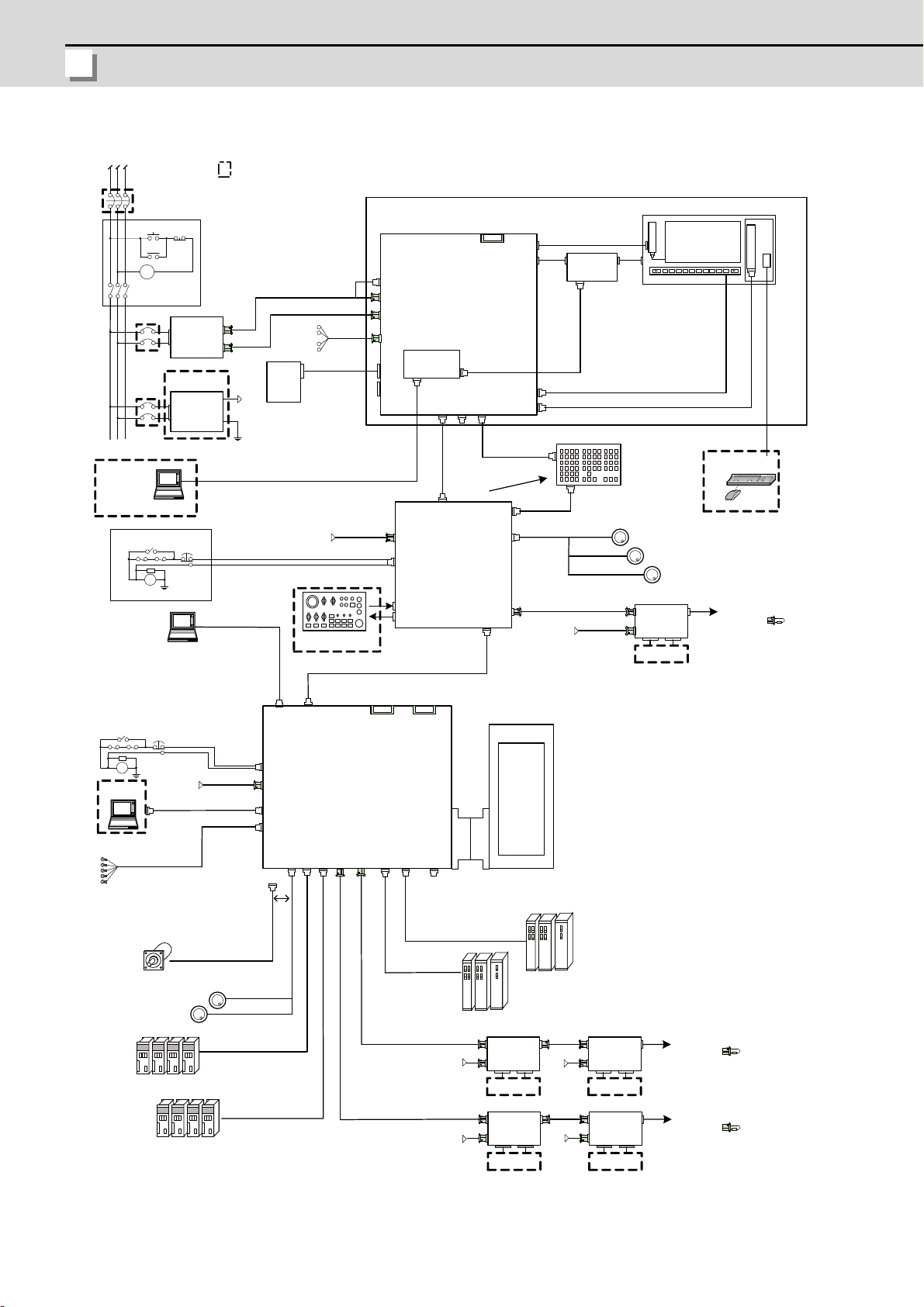
I General Specifications (M700VW Series)
MITSUBISHI CNC
Motor group
Auxiliary axis
Servo/Spindle
drive unit
MR-J2-CT/CT4 Series
Auxiliary axis Servo
drive unit
Manual pulse generator
Manual pulse penerator
Expansion unit
Control unit
Display unit
Keyboard unit
Remote I/O unit
Synchronous
feed encoder
Remote I/O unit
Operation panel
I/O unit
MDS-D/DH/DM Series
MDS-D-SVJ3/SPJ3 Series
Expansion card
Hard disk unit
(Note) For the drive unit configuration, refer to the Instruction Manual of the drive unit you use.
I - 2
Page 25

I - 3
2
General Connection
Diagram
Page 26
I General Specifications (M700VW Series)
MITSUBISHI CNC
2.1 For 10.4-type Display Unit
24Vdc
RIO1
DCIN
RIO2
FCUA-R211
/SH41
24Vdc
RIO1
DCIN
RIO2
SV1
LAN1
CF
OPT1
EXT-CON
SV2
SIO×2
RIO1
Slot1
OPI
LAN(user)
EMG
24Vdc
RIO1
DCIN
RIO2
FCUA-R211
/SH41
24Vdc
RIO1
DCIN
RIO2
MC
RST
ON OFF
MC
DCOUT
ON/OFF
ACIN
CP
PD2 7
DCOUT
FG
ACIN
DCIN
CF01
HDD
INV
LVDS
MC
24Vdc
F110
24Vdc
RA
FG
FG
EMG
F070
G171
DCIN
CF24
EMG
MENUKEY
MPG
RIO3
F020/F021/F022
Mouse
USB1USB2
FRONT_OUT
PC Keyboard
ON
G170
ON/OFF
F120
HDD
CF25
USB
HN273/274
RIO2
LAN
PCLAN
DX101
24Vdc
RIO1
DCIN
RIO2
Remote I/O unit
Machine I/O
24Vdc
F070
DCIN
F040/F041
MPG/
ENC
SIO
G018
FCU7-KB021/KB022/KB041/KB045
<G290>
<G291>
<G301>
SKIP
F023/F024
(Max: 20m)
(5V)
F034/F035
SH21
SH21
F120
(5V/12V )
F070
<G990>
F140
RA
FG
EMG
<G485>
FCU7-MU031/041
FCU7-MA041
FCU7-EX891
G395/G396/G380
OPT 2
FCUA-R211/SH41
FCUA-R211/SH41
FCU7-
DX670/671/770/771
CG3x
G031/G0 3 2
G020/G021/G022
NCRST
SDIO
FCUA -DX1xx
FCUA -DX1xx
FCUA -DX1xx
FCUA -DX1xx
G395/G396/G380
FCUA-R211/SH41
CP
HN012
SIO
USB
CF
FCU7-HD002-001
TPOUT
OFF
OPI
(NFB)
MDS-D/DH/SVJ3/SPJ3
MDS-D/DH/SVJ3/SPJ3
MDS-C/CH/SVJ2/SPJ2
MDS-C/CH/SVJ2/SPJ2
FCUA-R030
FCU7-DA646-11/31
Skip signal input
Machine I/O Machine I/O
RS232C
Remote I/O unit
Machine I/O Machine I/O
10.4-type LCD
24VDC stabilized
power supply
Backlight inverter
Machine operation
panel
OT release SW
RS232C
device
Dotted lines indicate the sections prepared by the machine tool builder.
PCMCIA slot
Keyboard unit
Can be added onto
back of keyboard
CNC control unit
Expansion Unit
Spindle/Servo drive units
Operation panel
I/O unit
Synchronous feed
encoder
Manual pulse
generator
10.4-type Display unit
Spindle/Servo drive units
Spindle/Servo drive units
Spindle/Servo drive units
Remote I/O unit
Remote I/O unit
Remote I/O unit
No-fuse breaker
The name with brackets <>
indicates the cable for the unit.
To the next remote I/O
or terminator
Menu key
PC Board
MI-CM15-M5A
HN273 : with touch panel function
HN274 : without touch panel function
Hard disk unit
Can be added onto
back of keyboard
To the next remote I/O
or terminator
device
To the next remote I/O
or terminator
Manual pulse
generator
OT release SW
I - 4
(Note) As for drive units, only the brief diagram is given here. Refer to the drive unit's manual for details.
Page 27

M700V Series Specifications Manual
2 General Connection Diagram
2.2 For 15-type Display Unit
24Vdc
RIO1
DCIN
RIO2
FCUA-R211
/SH41
24Vdc
RIO1
DCIN
RIO2
SV1
LAN1
CF
OPT1
EXT-CON
SV2
SIO×2
RIO1
Slot1
OPI
LAN(user)
EMG
24Vdc
RIO1
DCIN
RIO2
FCUA-R211
/SH41
24Vdc
RIO1
DCIN
RIO2
MC
RST
ON OFF
MC
DCOUT
ON/OFF
ACIN
CP
PD2 7
DCOUT
FG
ACIN
DCIN
CF01
HDD
INV
LVDS
MC
24Vdc
F110
24Vdc
RA
FG
FG
EMG
F070
G171
DCIN
CF24
EMG
MENUKEY
MPG
RIO3
F020/F021/F022
Mouse
USB1USB2
FRONT_OUT
PC Keyboard
ON
G170
ON/OFF
F120
HDD
CF25
USB
RIO2
LAN
PCLAN
DX101
24Vdc
RIO1
DCIN
RIO2
24Vdc
F070
DCIN
F040/F041
MPG/
ENC
SIO
G018
FCU7-KB021/KB022/KB041/KB045
<G290>
<G291>
<G301>
SKIP
F023/F024
(Max: 20m)
(5V)
F034/F035
SH21
SH21
F120
(5V/12V )
F070
F140
RA
FG
EMG
FCU7-MU031/041
FCU7-MA041
FCU7-EX891
G395/G396/G380
OPT 2
FCUA-R211/SH41
FCUA-R211/SH41
FCU7-
DX670/671/770/771
CG3x
G031/G0 3 2
G020/G021/G022
NCRST
SDIO
FCUA -DX1xx
FCUA -DX1xx
FCUA -DX1xx
FCUA -DX1xx
G395/G396/G380
FCUA-R211/SH41
CP
HN012
SIO
USB
CF
FCU7-HD002-001
TPOUT
OFF
OPI
(NFB)
MDS-D/DH/SVJ3/SPJ3
MDS-D/DH/SVJ3/SPJ3
MDS-C/CH/SVJ2/SPJ2
MDS-C/CH/SVJ2/SPJ2
FCUA-R030
LVDS I/F
SET
<G483>
<G092-A>
HN241
<G420>
MI-CM15-M5A
FCU7-DA636-11/31
Remote I/O unit
Machine I/O
Skip signal input
Machine I/O Machine I/O
RS232C
Remote I/O unit
Machine I/O Machine I/O
15-type LCD
24VDC stabilized
power supply
Backlight inverter
Machine operation
panel
OT release SW
RS232C
device
Dotted lines indicate the sections prepared by the machine tool builder.
PCMCIA slot
Keyboard unit
Can be added onto
back of display unit
CNC control unit
Expansion Unit
Spindle/Servo drive units
Operation panel
I/O unit
Synchronous feed
encoder
Manual pulse
generator
Spindle/Servo drive units
Spindle/Servo drive units
Spindle/Servo drive units
Remote I/O unit
Remote I/O unit
Remote I/O unit
No-fuse breaker
The name with brackets <>
indicates the cable for the unit.
To the next remote I/O
or terminator
Menu key
PC Board
Hard disk unit
Can be added onto
back of keyboard
To the next remote I/O
or terminator
device
To the next remote I/O
or terminator
Manual pulse
generator
OT release SW
15-type Display unit
HN241 : Touch panel I/F card
(Note) As for drive units, only the brief diagram is given here. Refer to the drive unit's manual for details.
I - 5
Page 28

I - 6
Page 29

I - 7
3
List of Configuration
Page 30
I General Specifications (M700VW Series)
MITSUBISHI CNC
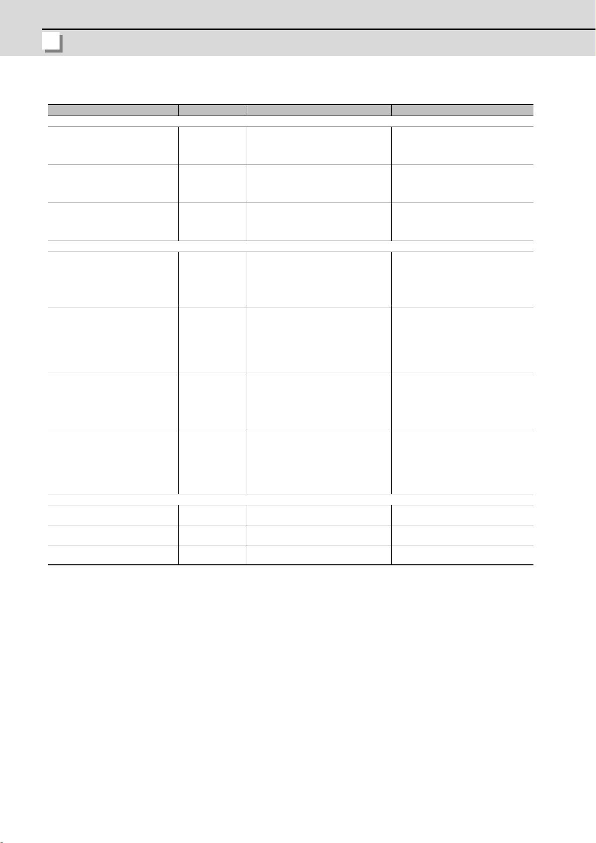
3.1 List of Units
Classification Type Components Remarks
[Control unit]
NC functions
For 720VW
NC functions
For 730VW
NC functions
For 750VW
[Display unit]
10.4-type color TFT
(VGA:640*480)
Panel computer
10.4-type color TFT touch panel
(VGA:640*480)
Panel computer
15-type color TFT
(XGA:1024*768)
Panel computer
15-type color TFT touch panel
(XGA:1024*768)
Panel computer
[Keyboard unit]
Keyboard Clear keys for 8.4-type display
unit
Keyboard Clear keys for 8.4-type display
unit
Keyboard Clear keys for 10.4-type
display unit
FCU7-MU031
FCU7-MU041
FCU7-MA041
FCU7-DA646-11
FCU7-DA646-31
FCU7-DA636-11
FCU7-DA636-31
FCU7-KB021
FCU7-KB022
FCU7-KB041
Main control card
Base card
Power supply card
LED card
Main control card
Base card
Power supply card
LED card
Main control card
Base card
Power supply card
LED card
LCD panel
Backlight inverter
Menu keys
Inverter cable
LCD cable
Backlight cable
LCD panel
Backlight inverter
Menu keys
Inverter cable
LCD cable
Backlight cable
Touch panel
LCD panel
Backlight inverter
Menu keys
Inverter cable
LCD cable
Backlight cable
LCD panel
Backlight inverter
Menu keys
Inverter cable
LCD cable
Backlight cable
Touch panel
Escutcheon, key switch
G290 cable
Escutcheon, key switch
G290 cable
Escutcheon, key switch
G290 cable
Export Trade Control Ordinance an d Foreign
Trade Ordinance noncompliant unit
Export Trade Control Ordinance an d Foreign
Trade Ordinance noncompliant unit
Export Trade Control Ordinance an d Foreign
Trade Ordinance compliant unit
PCMCIA II card I/F is normally equipped with
the display unit
PCMCIA II card I/F is normally equipped with
the display unit
PCMCIA II card I/F is normally equipped with
the display unit
PCMCIA II card I/F is normally equipped with
the display unit
ONG layout for machining center
ONG layout for lathe
ABC layout
I - 8
Page 31

M700V Series Specifications Manual
3 List of Configuration
Classification Type Components Remarks
[Operation panel I/O unit]
Base card
DI 24V/0V common input
DO Sink output
DI 24V/0V common input
DO Source output
DI 24V/0V common input
DO Sink output
DI 24V/0V common input
DO Source output
[Hard Disk Unit]
External memory device FCU7-HD002-1
[Remote I/O unit]
24V/0V common input + Sink output FCUA-DX100 RX311
24V/0V common input + Sink output FCUA-DX110 RX311+RX321-1
24V/0V common input + Sink output
+ Analog output
24V/0V common input + Sink output
+ Analog input/output
24V/0V common input + Source output FCUA-DX101 RX312
24V/0V common input + Source output FCUA-DX111 RX312+RX322-1
24V/0V common input + Source output +
Analog output
24V/0V common input + Source output +
Analog input/output
FCU7-DX670
FCU7-DX671
FCU7-DX770
FCU7-DX771
FCUA-DX120 RX311+RX321
FCUA-DX140 RX311+RX341
FCUA-DX121 RX312+RX322
FCUA-DX141 RX312+RX341
Mounting bracket
G301 cable
G310 cable
Terminator (R-TM)
Base card
Mounting bracket
G301 cable
G310 cable
Terminator (R-TM)
Base card
Add-on card
Mounting bracket
G301 cable
G310 cable
Terminator (R-TM)
Base card
Add-on card
Mounting bracket
G301 cable
G310 cable
Terminator (R-TM)
Hard disk
Mounting plate,
cushioning rubber
F140 cable (50cm)
DI: 32-points 24V/0V common type
DO: 32-points sink type (output 60mA)
Output insulation type
Display-main body relay I/F
MPG:3ch
Emergency stop input
Remote I/O 1ch (160 points/160 points)
DI: 32-points 24V/0V common type
DO: 32-points sink type (output 60mA)
Output insulation type
Display-main body relay I/F
MPG:3ch
Emergency stop input
Remote I/O 1ch (160 points/160 points)
DI: 64-points 24V/0V common type
DO: 64-points sink type (output 60mA)
Output insulation type
Display-main body relay I/F
MPG:3ch
Emergency stop input
Remote I/O 1ch (128 points/128 points)
DI: 64-points 24V/0V common type
DO: 64-points sink type (output 60mA)
Output insulation type
Display-main body relay I/F
MPG:3ch
Emergency stop input
Remote I/O 1ch (128 points/128 points)
DI: 32-points 24V/0V common type
(photo coupler insulation)
DO: 32-points sink type (non-insulation)
Number of occupied stations: 1
DI: 64-points 24V/0V common type
(photo coupler insulation)
DO: 48-points sink type (non-insulation)
Number of occupied stations: 2
DI: 64-points 24V/0V common type
(photo coupler insulation)
DO: 48-points sink type (non-insulation)
AO: 1 point
Number of occupied stations: 2
DI: 32-points 24V/0V common type
(photo coupler insulation)
DO: 32-points sink type (non-insulation)
AI: 4 points
AO: 1 point
Number of occupied stations: 2
DI: 32-points 24V/0V common type
(photo coupler insulation)
DO: 32-points source type (non-insulation)
Number of occupied stations: 1
DI: 64-points 24V/0V common type
(photo coupler insulation)
DO: 48-points source type (non-insulation)
Number of occupied stations: 2
DI: 64-points 24V/0V common type
(photo coupler insulation)
DO: 48-points source type (non-insulation)
AO: 1 point
Number of occupied stations: 2
DI: 32-points 24V/0V common type
(photo coupler insulation)
DO: 32-points source type (non-insulation)
AI: 4 points
AO: 1 point
Number of occupied stations: 2
I - 9
Page 32

I General Specifications (M700VW Series)
MITSUBISHI CNC
Classification Type Components Remarks
[Scan I/O card]
Sink type HR347 HR347
Source type HR357 HR357
[External power supply unit]
External power supply with power supply
ON/OFF function
External power supply with power supply
ON/OFF function
[Manual pulse generator]
5V Manual pulse generator UFO-01-2Z9
12V Manual pulse generator HD60 HD60
[Encoder]
Synchronous feed encoder OSE1024-3-15-68 OSE1024-3-15-68
[Expansion Unit]
Expansion unit x 1slot FCU7-EX891
[Expansion Card]
PROFIBUS-DP FCU7-HN571 HN571 PROFIBUS-DP x 1ch
CC-Link FCU7-HN576 HN576 CC-Link x 1ch
CC-Link FCU7-HN577 HN577 CC-Link x 2ch
PD25
PD27
Power supply card
Case set
Power supply card
Case set
UFO-01-2Z9
(Produced by NIDEC NEMICON)
HR891
Mounting plate, case set
Scan DI/DO = 64 points/64 points
DI/DO = 32 points/32 points
Scan DI/DO = 64 points/64 points
DI/DO = 32 points/32 points
Input 200VAC
Output 24VDC (3A)
Input 200 to 400VAC
Output 24VDC (8A)
Input 5VDC
100pulse/rev
Input 12VDC
25pulse/rev
Input 5VDC
1024pulse/rev
One expansion card HN5xx can be mounted
additionally.
(Note 1) Operation panel I/O unit can be mounted on the back side of the keyboard unit.
(Note 2) DI: Digital input signals, DO: Digital output signals, AI: Analog input signals, AO: Analog output
signals
I - 10
Page 33

M700V Series Specifications Manual
3 List of Configuration
3.2 Durable Parts
Battery for control unit and display unit Q6BAT
Backlight for FCU7-DA646-11/31 104LHS49
Backlight for FCU7-DA636-11/31 AA-L5902174G01
Touch panel protective sheet for FCU7-DA646-31 BN939B036G51
Touch panel protective sheet for FCU7-DA636-31 BN939B060G61
Control unit cooling fan 109P0412H731
Display unit cooling fan MMF-06G24DS-RP2
3.3 Replacements
Protection fuse LM40
Front memory interface card CF-700 USB-PC-CARD
Durable parts Part type
Replacements Part type
I - 11
Page 34

I General Specifications (M700VW Series)
MITSUBISHI CNC
3.4 List of Cables
Type Application
CNP2E-1-*M Motor side PLG cable 2, 3, 4, 5, 7, 10, 15, 20, 25, 30 30m
CNV2E-6P-*M
CNV2E-7P-*M
CNV2E-8P-*M
CNV2E-9P-*M
CNV2E-D-*M MDS-B-SD unit cable 2, 3, 4, 5, 7, 10, 15, 20, 25, 30 30m
CNV2E-HP-*M MDS-B-HR unit cable 2, 3, 4, 5, 7, 10, 15, 20, 25, 30 30m
CNV2E-K1P-*M Detector cable for HF-KP motor (load side angle) 2, 3, 5, 7, 10 10m
CNV2E-K2P-*M Detector cable for HF-KP motor (reverse load side angle) 2, 3, 5, 7, 10 10m
DG21-*M
DG22-*M
E-TM OPI connector terminator - F020
F021
F022
F034 L*M RS-232C I/F cable: 1ch 0.5, 1, 2, 3, 5, 8, 10 15m (*)
F035 L*M RS-232C I/F cable: 2ch 0.5, 1, 2, 3, 5, 8, 10 15m (*)
F070 L*M 24VDC power cable 0.5, 1.5, 3, 5, 8, 10, 15, 20 30m
F110 L*M 24VDC power cable for PD25/PD27 0.5, 1.5, 3, 5, 8, 10, 15 15m
F120 L*M Emergency stop cable 0.5, 1.5, 3, 5, 8, 10, 15, 20 30m
F140 HDD 0.5 0.5m
F170 L*M ON/OFF switch cable for PD25/PD27 0.5, 1.5, 3, 5, 8, 10, 15 15m
F320 L*M
F321 L*M
FCUA-R030-*M SKIP input 3, 7 20m
FCUA-R031-*M Analog input/output 2, 3, 7 30m
FCUA-R050-*M Encoder input (straight, with connector) 5 30m
FCUA-R054-*M Encoder input (right angle, with connector) 3, 5, 10, 15, 20 30m
FCUA-R211-*M Remote I/O (with terminal block) 0.3, 1, 2, 5, 8, 10, 15, 20 30m (*)
FCUA-R300
FCUA-R301-*M
G018
G020
G021
G022
G023 L*M
G024 L*M
G031 RS-232C I/F cable: 1ch 0.5, 1, 2, 3, 5, 7, 10, 15 15m (*)
Motor side detector cable (for A74/ A51)/
Ball screw side detector cable
Motor side detector cable (for A74/ A51)/
Ball screw side detector cable
Motor side detector cable (for A48)/
Ball screw side detector cable
Motor side detector cable (for A48)/
Ball screw side detector cable
Battery cable
(For drive unit - battery unit)
Battery cable
(For servo drive unit - servo drive unit)
* This cable is required to supply the power from the battery unit to
multiple drive units.
Manual pulse generator cable (12V): 1ch
(for connection to operation panel I/O unit)
Manual pulse generator cable (12V): 2ch
(for connection to operation panel I/O unit)
Manual pulse generator cable (12V): 3ch
(for connection to operation panel I/O unit)
Manual pulse generator cable (12V): 1ch
(for connection to operation panel I/O unit)
Manual pulse generator cable (12V): 2ch
(for connection to operation panel I/O unit)
DI/DO cable (one side connector)
(for remote I/O unit)
DI/DO cable (both side connectors)
(for remote I/O unit)
I/O interface
Connect between control unit and operation panel I/O unit.
Manual pulse generator cable (5V): 1ch
(for connection to operation panel I/O unit)
Manual pulse generator cable (5V): 2ch
(for connection to operation panel I/O unit)
Manual pulse generator cable (5V): 3ch
(for connection to operation panel I/O unit)
Manual pulse generator cable (5V): 1ch
(for connection to control unit)
Manual pulse generator cable (5V): 2ch
(for connection to control unit)
Length (m) of cables provided
by Mitsubishi
2, 3, 4, 5, 7, 10, 15, 20, 25, 30 30m
2, 3, 4, 5, 7, 10, 15, 20, 25, 30 30m
2, 3, 4, 5, 7, 10, 15, 20, 25, 30 30m
2, 3, 4, 5, 7, 10, 15, 20, 25, 30 30m
0.3, 0.5, 1, 5 5m
0.3, 0.5, 1, 5 5m
0.5, 1, 2, 3, 5, 7, 10, 20 50m
1, 2 50m
1, 2 50m
1, 2, 3, 5, 8, 10, 15, 20 50m
1, 2, 3, 5, 8, 10, 15, 20 50m
3 50m
1, 2, 3, 5 50m
1, 2, 3, 5, 7, 10, 15, 20 20m
2 20m
2 20m
2 20m
1, 2, 3, 5, 8, 10, 15, 20 20m (*)
1, 2, 3, 5, 8, 10, 15, 20 20m (*)
Max. cable
length
I - 12
Page 35

M700V Series Specifications Manual
3 List of Configuration
Type Application
G032 RS-232C I/F cable: 2ch 0.5, 1, 2, 3, 5, 7, 10, 15 15m (*)
G123 Emergency stop terminator - -
G170
G171
G290
G300 L*M
G301 L*M
G310 NC reset 15m 0.1m
G380 L*M
G395 L*M
G396 L*M
G430 For connection to handy terminal 3, 5, 10 10m
MR-BKS1CBL*MA1-H
MR-BKS1CBL*MA2-H
MR-PWS1CBL*MA1-H
MR-PWS1CBL*MA2-H
R-TM
SH21 Power supply communication cable
SH41
ON/OFF switch
Connect between ON/OFF switch and display unit.
Power supply ON/OFF
Connect between display unit and PD25/PD27 power supply unit.
USB cable
Enclosed with keyboard unit.
LAN cross cable
(Shielded cable is recommended when the length will be 1m or more)
LAN straight cable
(Shielded cable is recommended when the length will be 1m or more)
Optical communication cable (PCF type with reinforced sheath)
(for wiring outside of the panel)
Optical communication cable (POF type with reinforced sheath)
(for wiring outside of the panel)
Optical communication cable (POF type without reinforced sheath)
(for wiring inside of the panel)
Brake cable for HF-KP motor (load side angle) 2, 3, 5, 7, 10 10m
Brake cable for HF-KP motor (reverse load side angle) 2, 3, 5, 7, 10 10m
Power cable for HF-KP motor (load side angle) 2, 3, 5, 7, 10 10m
Power cable for HF-KP motor (reverse load side angle) 2, 3, 5, 7, 10 10m
Remote I/O
Interface terminator
Remote I/O
(between units in a panel)
Length (m) of cables provided
by Mitsubishi
0.35, 0.5, 1, 1.5, 2, 3, 5, 10, 15 15m
0.5, 1, 3, 5, 7, 10, 15 15m
0.7m 1m
1, 3, 5, 10 10m
11m
5, 10, 12, 15, 20 20m
1, 2, 3, 5, 10 10m
0.3, 0.5, 1, 2, 3, 5 10m
--
0.35, 0.5, 0.7, 1, 1.5, 2, 2.5, 3,
3.5, 4, 4.5, 5, 6, 7, 8, 9, 10, 15,
20, 30
0.3, 0.5, 0.7 1m (*)
Max. cable
length
30m
(Note 1) Asterisks "*" in type columns indicate cable length (unit: m).
(Note 2) Lengths indicated with an asterisk (*) in the max. cable length column indicate the maximum cable
length when connecting to the control unit via other unit.
I - 13
Page 36

I - 14
Page 37

I - 15
4
Environment Conditions
Page 38

I General Specifications (M700VW Series)
MITSUBISHI CNC
Item
General
Specificati
ons
Required
power
specificatio
ns
Others
Unit name Control unit Display unit Keyboard unit
Type
During
Ambient
temperature
Ambient
humidity
Vibration
resistance
Shock
resistance
Working
atmosphere
Power voltage
Power capacity 2.5A
Instantaneous
stop tolerance
time
Heating value (max) 16W
Mass (kg) 1.1
Outline
dimension
operatio
n
During
storage
Long
term
Short
term
(mm)
FCU7-MU031/041
FCU7-MA041
24VDC ± 5%
Ripple noise 200mV (P-
P)
76(width) x 168(height)
x 155(depth)
FCU7-DA646-*1/
636-*1
10 to 75% RH (with no dew condensation)
10 to 95% RH (with no dew condensation) (Note 1)
2
or less (during operation)
4.9m/s
2
29.4m/s
No corrosive gases, dust or oil mist
PD25 or PD27
(AC-24VDC power
supply unit)
3A(when using PD25)
8A(when using PD27)
20ms - 20ms
FCU7-DA646:48W
FCU7-DA636:54W
FCU7-DA646:4.0
FCU7-DA636:6.0
FCU7-DA646:
260(width) x 220(height)
FCU7-DA636:
400(width) x 320(height)
or less (during operation)
FCU7-KB021/022/041
0 to 55C°
-20 to 60C°
Provided by the display
FCU7-KB021/022:1.0
140(width) x 200(height)
230(width) x 220(height)
unit
-0.7A
-
FCU7-KB041:1.5
FCU7-KB021/022:
FCU7-KB041:
Operation panel
I/O unit
FCU7-DX670/671/770/
771
24VDC ± 5%
Ripple noise 200mV (P-
P)
Control section: 5.0W
(Note 3)
0.6
116(width) x 167(height)
I - 16
Page 39

M700V Series Specifications Manual
4 Environment Conditions
Item
General
Specificati
ons
Required
power
specificatio
ns
Others
Ambient
temperature
Ambient
humidity
Vibration resistance
Shock resistance
Working atmosphere No corrosive gases or dust
Input power voltage
Power capacity 24V 0.7A (Note 4) 24V 1.5A (Note 4) 24V 0.7A (Note 4)
Instantaneous stop
tolerance time
Heating value (max.) 25W (Note 5) 30W (Note 5) 30W (Note 5)
Mass 0.5kg 0.6kg 0.6kg 0.6kg
Unit name Remote I/O unit
Type FCUA-DX10* FCUA-DX11* FCUA-DX12* FCUA-DX14*
During
operation
During
storage
Long term 10 to 75% RH (with no dew condensation)
Short
term
10 to 95% RH (with no dew condensation) (Note 1)
4.9m/s
29.4m/s
24VDC ± 5% Ripple noise 200mV (P-P)
0 to 55C°
-20 to 60C°
2
or less (during operation)
2
or less (during operation)
-
(Note 1) "Short term" means within one month.
(Note 2) For the current value of the I/O circuit, calculate with the number of points used and load.
(Note 3) For the heating value of the I/O circu it, calculate with the number of points used.
(Note 4) Allows only the amount to be consumed by control circuit.
(Note 5) Differs according to the number of mac hin e input operation points and the load and number of
points connected to the machine output. The maximum value applies when all poin ts are ON.
(Note 6) MITSUBISHI CNC M700VW Series, which is an open equipment, must be installed within a sealed
metal control panel.
I - 17
Page 40

I - 18
Page 41

I - 19
5
Hardware Specifications
Page 42

I General Specifications (M700VW Series)
MITSUBISHI CNC
5.1 Control Unit
10
25
50 168
155 60
76
50
Control unit
(Space required for
cable insertion)
(Space required for wiring)
(Space required
above the unit)
(Space required for wiring)
(Under the front cover)
(10)
(9)
(8)
(11)
(15)
(16)
(14)
(5)
(4)
(3)
(12)
(13)
(1)
(2)
(6)
(7)
(17)
(19)
(18)
Dimension and names of parts
[FCU7-MU031 / FCU7-MU041 / FCU7-MA041]
Connector
No.
(1) SV1 Auxiliary axis communication I/F (11) SDIO Safety observing input/output I/F
(2) SV2 Auxiliary axis communication I/F (12) RIO1 Remote I/O unit I/F
(3) OPT1 Optical communication I/F (13) RIO2 Remote I/O unit I/F
(4) OPT2 Optical communication I/F (14) DCIN 24VDC input
(5) LAN1 Ethernet I/F (15) CF01 Power OFF input
(6) FG FG terminal (16) EMG External emergency stop input
(7) SKIP Skip input 8ch (17) USB USB I/F
(8) OPI Operation panel I/O unit I/F (18) CF CF card I/F
(9) SIO RS-232C communication I/F 2ch (19) BAT Battery (Q6BAT) I/F
(10) ENC
name
Encoder input 1ch
(5V manual pulse generator input 2ch)
Function No.
Connector
name
Function
I - 20
Page 43

M700V Series Specifications Manual
5 Hardware Specifications
[With expansion unit (FCU7-EX891)]
10
168 100
157 60
76 40
100
25
Control unit
Expansion unit
(Space required for wiring)
(Space required
for wiring)
(Space required
for cable insertion)
(Space required for wiring)
(10)
(9)
(8)
(11)
(15)
(16)
(14)
(5)
(4)
(3)
(12)
(13)
(1)
(2)
(6)
(7)
I - 21
Page 44

I General Specifications (M700VW Series)
MITSUBISHI CNC
<Installation dimension drawing>
3-M5
screw
10 1
20 11
Control unit only With expansion unit
3-M5
screw
6 156 (16)
(6) 64 6
Top
Bottom
(1) Auxiliary axis communication I/F (SV1)
Top
156 6 (16)
40
64 (6) 6
Bottom
1 GND 11 GND
2 O SVTXD1 12 O SVTXD1*
3 I SVALM1 13 I SVALM1*
4 I SVRXD1 14 I SVRXD1*
5 GND 15 GND
6 NC 16 NC
7 O SVEMG1 17 O SVEMG1*
8 NC 18 NC
9 NC 19 NC
10 NC 20 NC
* Connect connector case with FG pattern.
<Cable side connector type>
Plug: 10120-3000VE
Shell: 10320-52F0-008
Recommended manufacturer: Sumitomo 3M
I - 22
Page 45

M700V Series Specifications Manual
5 Hardware Specifications
(2) Auxiliary axis communication I/F (SV2)
10 1
20 11
1 GND 11 GND
2 O SVTXD2 12 O SVTXD2*
3 I SVALM2 13 I SVALM2*
4 I SVRXD2 14 I SVRXD2*
5 GND 15 GND
6 NC 16 NC
7 O SVEMG1 17 O SVEMG1*
8 NC 18 NC
9 NC 19 NC
10 NC 20 NC
* Connect connector case with FG pattern.
<Cable side connector type>
Plug: 10120-3000VE
Shell: 10320-52F0-008
Recommended manufacturer: Sumitomo 3M
(3) Optical communication I/F (OPT1)
(4) Optical communication I/F (OPT2)
<Cable side connector type>
(PCF type)
Connector: CF-2D101-S
Recommended manufacturer: Japan Aviation Electronics
(POF type)
Connector: PF-2D101
Recommended manufacturer: Japan Aviation Electronics
I - 23
Page 46

I General Specifications (M700VW Series)
MITSUBISHI CNC
(5) Ethernet I/F (LAN1)
81
10 1
20 11
1 OTD+
2 OTD-
3 I RD+
4
5
6 I RD-
7
8
* Connect connector case with FG pattern.
* Use cross cable (G300) when directly connecting a device such as a personal computer to
the unit.
<Cable side connector type>
Connector: 5-569550-3
Recommended manufacturer: Tyco Electronics AMP
(6) FG terminal (FG)
(7) Skip input 8ch (SKIP)
1 0V 11 0V
2 I SKIP0 12 I SKIP1
3 I SKIP2 13 I SKIP3
4 NC 14 NC
5 0V 15 0V
6 NC 16 NC
7 I SKIP4 17 I SKIP5
8 I SKIP6 18 I SKIP7
9 NC 19 NC
10 NC 20 NC
* Connect connector case with FG pattern.
I - 24
<Cable side connector type>
Plug: 10120-3000VE
Shell: 10320-52F0-008
Recommended manufacturer: Sumitomo 3M
Page 47

M700V Series Specifications Manual
5 Hardware Specifications
(a) Skip signal input conditions
0V
+24V
Ton
External signal
Internal signal
Connection to 24V common
0V
+24V
Ton
External signal
Internal signal
Connection to 0V common
0V(RG)
0V(RG)
0V(RG)
SKIP
SKIP
COM
COM
24VDC
(Machine side)
Control
circuit
Control
circuit
(Machine side)
Connection to 24V common
Connection to 0V common
24VDC
Use the input signal within the following condition ranges.
Input voltage at external contact ON 18V or more, 25.2V or less
Input current at external contact ON 6mA or more
Input voltage at external contact OFF 4V or less
Input current at external contact OFF 2mA or less
Input signal holding time (Ton) 2ms or more
Internal response time 0.08ms or less
Machine side contact capacity +30V or more, 16mA or more
(Note) "Input voltage at external contact ON" means the voltage between the external input
signal and the COM terminal.
I - 25
Page 48

I General Specifications (M700VW Series)
MITSUBISHI CNC
(8) Operation panel I/O unit I/F (OPI)
10 1
20 11
10 1
20 11
1 GND 11 GND
2 NC 12 NC
3 CMTT 13 CMTR
4 NC 14 NC
5 GND 15 GND
6 OPHYOUT 16 OPHYOUT*
7 IPHYIN 17 IPHYIN*
8 5V 18 NC
9 ORTXD3 19 ORTXD3*
10 I TMEMG 20 I TMEMG*
* Connect connector case with FG pattern.
<Cable side connector type>
Plug: 10120-3000VE
Shell: 10320-52F0-008
Recommended manufacturer: Sumitomo 3M
(Note) When not using OPI connector, connect the terminator connector E-TM (optional).
(9) Serial communication (RS-232C) I/F 2ch (SIO)
1 0V 11 0V
2 I RD1(RXD1) 12 OSD1(TXD1)
3 ICS1(CTS1) 13 ORS1(RTS1)
4 O DR1(DSR1) 14 IER1(DTR1)
5 0V 15 0V
6 NC 16 NC
7 I RD2(RXD2) 17 OSD2(TXD2)
8 ICS2(CTS2) 18 ORS2(RTS2)
9 O DR2(DSR2) 19 IER2(DTR2)
10 NC 20 NC
* Connect connector case with FG pattern.
I - 26
<Cable side connector type>
Plug: 10120-3000VE
Shell: 10320-52F0-008
Recommended manufacturer: Sumitomo 3M
Page 49

M700V Series Specifications Manual
5 Hardware Specifications
(10) Encoder input 1ch/ 5V manual pulse generator input 2ch (ENC)
10 1
20 11
T
b da c e
A(B) phase
B(A) phase
Z phase
1 0V 11 0V
2 I ENC1C 12 IENC1C*
3 I ENC1B 13 IENC1B*
4 I ENC1A 14 IENC1A*
5 0V 15 0V
6 O5V 16 O5V
7 IHA2A 17 IHA2B
8 IHA1A 18 IHA1B
9 NC 19 NC
10 O5V 20 O5V
* Connect connector case with FG pattern.
<Cable side connector type>
Plug: 10120-3000VE
Shell: 10320-52F0-008
Recommended manufacturer: Sumitomo 3M
(a) Synchronous feed encoder input conditions
Input pulse signal type
Input signal voltage
Voltage of encoder power supply
Current consumption 200mA or less
Number of pulses per rotation 1024 pulse/rev
Cable length 50m or less
A and B phases (with phase difference 90°), Z phase
(Refer to the waveform below.)
H level 3.5V to 5.25V
L level 0V to 0.5V
5VDC ± 10%
a.b.c.d.e: A phase or B phase rising edge (falling edge) phase difference = T/4 ± T/10
I - 27
Page 50

I General Specifications (M700VW Series)
MITSUBISHI CNC
(b) 5V manual pulse generator input conditions
T
b da c e
A(B) phase
B(A) phase
0V
+5V
4700pF
4
3
14
13
10
20
1
11
0V
+5V
4700pF
+5V
+5V
0V
0V
0V
HA1A
HA2A
HA1B
HA2B
Connector
pin No.
Control
circuit
Signal
input
Power
output
Input pulse signal type
Input signal voltage
A and B phases (with phase difference 90°)
(Refer to the waveform below.)
H level 3.5V to 5.25V
L level 0V to 0.5V
Max. input pulse frequency 100kHz
Pulse generators power supply voltage
5VDC ± 10%
Current consumption 100mA or less
Number of pulses per rotation 25 pulse/rev or 100 pulse/rev
Cable length 20m or less
a.b.c.d.e: A phase or B phase rising edge (falling edge) phase difference = T/4 ± T/10
T: A or B phase cycle (Min. 10μs)
(c) 5V manual pulse generator input/output circuit
I - 28
When using the synchronous feed encoder and the manual pulse generator at the same time,
connect the manual pulse generator to the operation panel I/O unit or use a distribution cable
made by the machine tool builder.
Page 51

M700V Series Specifications Manual
5 Hardware Specifications
(11) Safety observing input/output I/F (SDIO)
1A5A
1B5B
Pin I/O Function Pin I/O Function
1A COMMON terminal 1B GND(RG)
2A I SDI1 (Door 1 switch input) 2B I SDI2 (Door 2 switch input)
3A I
4A 24VDC 4B O
5A O
Pin
SDI1 to 2 Input
SDO1 to 3 Output 24V Max. 60mA
EMGIN1 (Emergency stop input for each part
system)
SDO2 (Contactor control output for each part
system)
Characteris
tic
Voltage Current Description
Refer to the
description
3B I
5B O
Sink input signal: 0V COM: 24V
Source input signal: 24V COM: 0V
Contactor shutoff signal output
(Note) The output voltage/current of the terminals SDO1 to 3 (with
24VDC/60mA) may not be sufficient to directly control the
contactor.
In such a case, use a relay and the like that operates under
24VDC/60mA between the control unit and the contactor.
EMGIN2 (Emergency stop input for each part
system)
SDO1 (Contactor control output for each part
system)
SDO3 (Contactor control output for each part
system)
<Cable side connector type>
Type: 51353-1000
Contact: 56134-9000
Recommended manufacturer: MOLEX
<Wire material>
Type: UL1061-2464 AWG22
Recommended manufacturer: Oki Electric Cable
Safety standards taken into consideration
(a) Machinery directive
98/37/EC Machinery directive
(b) Safety-related parts of control system Part1: General principles for design
EN954-1:1996 Safety of machine – Safety-related parts of control system Part1:
General principles for design
(c) Safety of machine
EN60204-1/1997 Safety of machine – Electrical equipment of machines; Part 1: General
requirements
I - 29
Page 52

I General Specifications (M700VW Series)
MITSUBISHI CNC
(12) Remote I/O unit I/F (RIO1)
13
13
Up to eight remote I/O stations can be connected.
1 I/O TXRX1
2 I/O TXRX1*
3 0V
<Cable side connector type>
Connector: 1-178288-3
Contact: 1-175218-2 x3
Recommended manufacturer: Tyco Electronics AMP
(13) Remote I/O unit I/F (RIO2)
Up to eight remote I/O stations can be connected.
1 I/O TXRX2
2 I/O TXRX2*
3 0V
<Cable side connector type>
Connector: 1-178288-3
Contact: 1-175218-2 x3
Recommended manufacturer: Tyco Electronics AMP
I - 30
Page 53

M700V Series Specifications Manual
5 Hardware Specifications
(14) 24VDC input (DCIN)
13
1 I +24V
2 0V
3 FG
<Cable side connector type>
Connector: 2-178288-3
Contact: 1-175218-5 x3
Recommended manufacturer: Tyco Electronics AMP
(a) Specifications of power supply
Consider the following characteristics when selecting the stabilized power supply (prepared by
machine tool builder). Use a power supply that complies with CE Marking or that follows the
safety standards given below.
[Stabilized power supply selection items]
Outpu t Voltage fluctuation
Power capacity 2.5A or more
Output holding time 20ms
Overcurrent protection Required
Item Standard setting
± 5% or less of
24VDC
Ripple noise 200mV (P-P)
CAUTION
[Standards]
Safety Standards: UL1950, CSA C22.2 No. 234 approved, IEC950 compliant
Noise Terminal Voltage: FCC Class A, VCCI-Class A
High Harmonics Current Restrictions: IEC61000-3- 2
(Note) 24VDC voltage may drop instantaneously due to rush current at the beginning of 24V
power supply to the control unit.
The level of voltage drop depends on the capacity of the power supply. Do not share
the power supply with the devices that have alarms to warn the voltage drop.
1. Using a stabilized power supply without overcurrent protection may cause the unit's failure due to
miswiring of 24V.
I - 31
Page 54

I General Specifications (M700VW Series)
MITSUBISHI CNC
(15) Power OFF input (CF01)
21
31
Use this when turning the control unit power OFF with an external source such as an ON/OFF switch.
Supply +24V to ACFAIL when using this connector.
1 IGND
2 IACFAIL
<Cable side connector type>
Connector: 51030-0330
Contact: 50084-8160 x2
Recommended manufacturer: MOLEX
(Note) Control unit can be used if this connector is not connected.
(16) External emergency stop input (EMG)
1 FG
2 I EMG IN
3 O+24V
<Cable side connector type>
Connector: 51030-0330
Contact: 50084-8160 x3
Recommended manufacturer: MOLEX
(Note) U se this when not using the operation panel I/O unit, or when installing an emergency stop
switch in the electric cabinet. Connect a terminator (G123 cable) when not using this
connector.
(17) USB I/F (USB)
(18) CF card I/F (CF)
Operation-guaranteed CF cards and SD memory cards ( SD-CF adapte r is required) ar e recommended .
(Refer to "General Specifications: Precautions for Use of Commercially Available CF cards".)
I - 32
(19) Battery (Q6BAT) I/F (BAT)
Page 55

M700V Series Specifications Manual
5 Hardware Specifications
(20) LED
Name Lamp state Details
Lit (Yellow green) 24V power is being supplied from the external power supply.
24VIN
DCOUT
PSEMG
BATALM
Not lit
Lit (Yellow green)
Not lit
Lit (Red)
Not lit
Lit (Red)
Not lit
24V power is not being supplied from the external power supply.
Check the other LEDs for another possible factor (failure) as follows:
- Disconnection of fuse
The followings are all successfully output; 5V and 3.3V generated from 24V; 1.2V, 1.3V,
1.5V, and 2.5V on the main control card or base card.
The followings may have caused an error:
- No 24V-power supply from the external power supply.
- Failure in any of the power output circuits.
- Failure in the 3.3V power output circuit.
- Failure of LED.
- Failure of the logic IC, which helps turn the LED on.
The followings may have caused an error:
- Pressing the emergency stop switch.
- Disconnection of the emergency stop cable.
- Disconnection of the G123 cable (when not used).
No emergency stop has occurred.
Check the other LEDs for another possible factor (failure) as follows:
- Failure in the 3.3V power output circuit.
- Failure of LED.
- Failure of the logic IC, which helps turn the LED on.
Battery voltage has dropped to 2.7V or less
Otherwise, the battery has not been mounted.
No battery alarm has occurred.
Check the other LEDs for another possible factor (failure) as follows:
- Failure in the 3.3V power output circuit.
- Failure of LED.
- Failure of the logic IC, which helps turn the LED on.
I - 33
Page 56

I General Specifications (M700VW Series)
MITSUBISHI CNC
5.2 Display Unit
220
290 20 110
(Space required for wiring)
Outline dimension
[FCU7-DA646-11 (10.4-type) ]
(Note) The space of 30mm or more should be provided above the display unit for maintenance.
<Panel cut dimension drawing>
Unit outline
220 ( )
290 (
Unit outline
280 ± 0.3
274
204
210 ± 0.3
4- M3
Screw
(Square hole)
)
I - 34
Page 57

M700V Series Specifications Manual
5 Hardware Specifications
[FCU7-DA646-31 (10.4-type with touch panel)]
290
220
20 110
(Space required for wiring)
290 (
)
280 ± 0.3
4- M3
220 ( )
210 ± 0.3
274
204
Unit outline
Screw
(Square hole)
Unit outline
(Note) The space of 30mm or more should be provided above the display unit for maintenance.
<Panel cut dimension drawing>
I - 35
Page 58

I General Specifications (M700VW Series)
MITSUBISHI CNC
[FCU7-DA636-11 (15-type)]
400
8 – M3
320
(unit outline)
screw
(unit outline)
320
400
20 110
(Space required for wiring)
(Note) The space of 30mm or more should be provided above the display unit for maintenance.
<Panel cut dimension drawing>
0.2
±
155
0.2
±
155
195
±
0.2
195
302
382
±
0.2
I - 36
Page 59

M700V Series Specifications Manual
5 Hardware Specifications
[FCU7-DA636-31 (15-type with touch panel)]
400
320
20 110
(Space required for wiring)
400
8 – M3
320
(unit outline)
screw
(unit outline)
(Note) The space of 30mm or more should be provided above the display unit for maintenance.
<Panel cut dimension drawing>
0.2
±
155
0.2
±
155
±
0.2
195
195
302
382
±
0.2
I - 37
Page 60

I General Specifications (M700VW Series)
MITSUBISHI CNC
Names of parts
10.5
15
5
168
220
(1)
(2)
(3)
(6) (7) (8) (11) (12)
(20)
(18)
(17)
(15)
(14)
(21)(22)
(4)
(10)(9)
(16)
(5)
(13)
(19)
[Unit rear view]
No.
(10) MENUKEY Menu key I/F (21) FAN2 CPU cooling FAN I/F
(11) BAT Battery (Q6BAT) I/F (22) FAN1 CPU cooling FAN I/F
(1) CF card I/F (CF)
Connector
name
(1) CF CF card I/F (12) HDD Hard disk I/F
(2) FRONT_OUT Front IC card I/F (13) SAVR (Not used)
(3) INV Backlight inverter I/F (14) LAN Ethernet I/F
(4) DCIN 24VDC input (15) LVDS Display unit signal I/F
(5) SIOPC
(6) CF01 ACFAIL input (17) USB1 USB I/F
(7) CF24 External ON/OFF switch I/F (18) USB2 USB I/F
(8) EMG External emergency stop input (19) FAN3 (Not used)
(9) USB-FDD (Not used) (20) ON/OFF PD25/PD27 ON/OFF signal input
Serial communication (RS-232C)
I/F 2ch
Operation-guaranteed CF cards and SD memory cards (SD-CF ada pter is required) are r ecommended.
(Refer to "General Specifications: Precautions for Use of Commercially Available CF cards".)
(2) Front IC card I/F (FRONT_OUT)
Function No.
Connector
name
(16) CRT (Not used)
Function
I - 38
Page 61

M700V Series Specifications Manual
5 Hardware Specifications
(3) Backlight inverter I/F (INV)
13
CAUTION
(4) 24VDC input (DCIN)
1 I +24V
2 0V
3 FG
<Cable side connector type>
Connector: 2-178288-3
Contact: 1-175218-5 x3
Recommended manufacturer: Tyco Electronics AMP
(a) Specifications of power supply
Consider the following characteristics when selecting the stabilized power supply (prepared by
machine tool builder). Use a power supply that complies with CE Marking or that follows the
safety standards given below.
[Stabilized power supply selection items]
Item Standard setting
Output Voltage fluctuation
Ripple noise 200mV (P-P)
Power capacity 2.5A or more
Output holding time 20ms
Overcurrent protection Required
± 5% or less of
24VDC
[Standards]
Safety Standards: UL1950, CSA C22.2 No.234 approved, IEC950 compliant
Noise Terminal Voltage: FCC Class A, VCCI-Class A
High Harmonics Current Restrictions: IEC61000-3- 2
(Note) 24VDC voltage may drop instantaneously due to rush current at the beginning of 24V
power supply to the display unit. The level of voltage drop depends on the capacity of
the power supply. Do not share the power supply with the devices that have alarms to
warn the voltage drop.
1. Using a stabilized power supply without overcurrent protection may cause the unit's failure due to
miswiring of 24V.
I - 39
Page 62

I General Specifications (M700VW Series)
MITSUBISHI CNC
(5) Serial communication (RS-232C) I/F 2ch (SIOPC)
10 1
20 11
21
1 0V 11 0V
2 I RD1(RXD1) 12 OSD1(TXD1)
3 ICS1(CTS1) 13 ORS1(RTS1)
4 I CD1(DCD1) 14 IER1(DTR1)
5 0V 15 0V
6 O DR1(DSR1) 16 I RI1(RI1)
7 I RD2(RXD2) 17 OSD2(TXD2)
8 ICS2(CTS2) 18 ORS2(RTS2)
9 I CD2(DCD2) 19 IER2(DTR2)
10 O DR2(DSR2) 20 I RI2(RI2)
* Connect connector case with FG pattern.
<Cable side connector type>
Plug: 10120-3000VE
Shell: 10320-52F0-008
Recommended manufacturer: Sumitomo 3M
(6) ACFAIL input (CF01)
1 IGND
2 IACFAIL
<Cable side connector type>
Connector: 51030-0330
Contact: 50084-8160 x2
Recommended manufacturer: MOLEX
I - 40
Page 63

M700V Series Specifications Manual
5 Hardware Specifications
(7) External ON/OFF switch I/F (CF24)
51
31
1 NC
2 IP-OFF
3 LG-OFF
4 LG-ON
5 IP-ON
* Use this to connect the power supply unit and display unit
<Cable side connector type>
Connector: 51030-0530
Contact: 50084-8160 x4
Recommended manufacturer: MOLEX
(8) External emergency stop input (EMG)
1 FG
2 I EMG IN
3 O +24V
<Cable side connector type>
Connector: 51030-0330
Contact: 50084-8160 x3
Recommended manufacturer: MOLEX
(Note) Connect a terminator (G123 cable) when not using.
(9) Not used (USB-FDD)
(10) Menu key I/F (MENUKEY)
(11) Battery (Q6BAT) I/F (BAT)
(12) Hard disk I/F (HDD)
(13) Not used (SAVR)
I - 41
Page 64

I General Specifications (M700VW Series)
MITSUBISHI CNC
(14) Ethernet I/F (LAN)
81
14
1 OTD+
2 OTD-
3 I RD+
4
5
6 I RD-
7
8
* Connect connector case with FG pattern.
* Use a straight cable (G301) for connection with the operation panel I/O unit.
<Cable side connector type>
Connector: 5-569550-3
Recommended manufacturer: Tyco Electronics AMP
(15) Display unit signal I/F (LVDS)
(16) Not used (CRT)
(17) USB I/F (USB1)
(18) USB I/F (USB2)
5V, max 500mA
1 OVcc
2 I/O -Data1/2
3 I/O +Data1/2
4 GND
* Connect connector case with FG pattern.
<Cable side connector type>
Connector: DUSB-APA42-A-C50
Contact: DUSB-PA1-100 (When AWG20 to 24)
Recommended manufacturer: DDK
I - 42
(19) Not used (FAN3)
Page 65

M700V Series Specifications Manual
5 Hardware Specifications
(20) PD25/PD27 ON/OFF signal input (ON/OFF)
41
1 GND
2 IPON
3 IPOFF
4 GND
<Cable side connector type>
Connector: 51030-0430
Contact: 50084-8160 x4
Recommended manufacturer: MOLEX
(21) CPU cooling FAN I/F (FAN2)
(22) CPU cooling FAN I/F (FAN1)
24V
I - 43
Page 66

I General Specifications (M700VW Series)
MITSUBISHI CNC
5.3 Keyboard Unit
(Space required for wiring)
Outline dimension
[FCU7-KB021]
(Note) The above side view shows the state with the operation panel I/O unit mounted.
<Panel cut dimension drawing>
140
(Unit outline)
0
0.3
(Square hole)
182
190 0.3
(Unit outline)
200
4-M3
122
Screw
I - 44
Page 67

M700V Series Specifications Manual
5 Hardware Specifications
[FCU7-KB022]
(Space required for wiring)
140
0
122
182
200
0.3
4-M3
190 0.3
Screw
(Unit outline)
(Unit outline)
(Square hole)
(Note) The above side view shows the state with the operation panel I/O unit mounted.
<Panel cut dimension drawing>
I - 45
Page 68

I General Specifications (M700VW Series)
MITSUBISHI CNC
[FCU7-KB041]
(Space required for wiring)
(Note) The above side view shows the state with the operation panel I/O unit mounted.
<Panel cut dimension drawing>
(Unit outline)
230
0.3
220
212
(Square hole)
210 0.3
202
4-M3
Screw
(Unit outline)
220
I - 46
Page 69

M700V Series Specifications Manual
5 Hardware Specifications
5.4 Operation Panel I/O Unit
Characteristics of operation panel I/O unit are as follows.
(1) Operation panel (display unit section) and electric cabinet (control unit section) can be wired with one
cable (G018).
This is effective to simplify the wiring between operation panel and electric cabinet, as well as to reduce
the cost of wiring.
G018 cable includes RI03, EMG and LAN.
(2) Number of DI/DO points that can be mounted on the machine operation pane l is 32/32 as standa rd and
64/64 at the maximum.
Both sink type and source type are available.
(3) Remote I/O interface --- 1ch
Remote I/O unit, card-sized I/O card, scan I/O card, etc. can be extended up to 5 channels.
Note that the following (a) and (b) will be applied if DI/DO mounted on the operation panel I/O unit is
used.
(a) When 32 points/32 points are used, up to 5 channels, or 160 points/160 points in total, are
available.
(b) When 64 points/64 points are used, up to 4 channels, or 128 points/128 points in total, are
available.
(4) Manual pulse generator --- 3ch
5V and 12V manual pulse generators can be connected.
(5) Emergency stop input --- 1ch
Emergency stop switch installed on the operation panel can be connected.
(6) LAN communication interface --- 1ch
Display unit can be connected.
(7) NC reset interface --- 1ch
NC can be reset by DI input. NC reset interface is connected to the keyb oa rd unit .
(8) Installation on the back side of the keyboard unit is possible.
Allows space saving inside the operation panel.
Classification Type Components Remarks
DI: 32-points 24V/0V common type
DO: 32-points sink type (output 60mA)
Output insulation type
Display-main body relay I/F
MPG:3ch
Emergency stop input
Remote I/O 1ch (160 points/160 points)
DI: 32-points 24V/0V common type
DO: 32-points sink type (output 60mA)
Output insulation type
Display-main body relay I/F
MPG:3ch
Emergency stop input
Remote I/O 1ch (160 points/160 points)
DI: 64-points 24V/0V common type
DO: 64-points sink type (output 60mA)
Output insulation type
Display-main body relay I/F
MPG:3ch
Emergency stop input
Remote I/O 1ch (128 points/128 points)
DI: 64-points 24V/0V common type
DO: 64-points sink type (output 60mA)
Output insulation type
Display-main body relay I/F
MPG:3ch
Emergency stop input
Remote I/O 1ch (128 points/128 points)
DI 24V/0V common input
DO Sink output
DI 24V/0V common input
DO Source output
DI 24V/0V common input
DO Sink output
DI 24V/0V common input
DO Source output
FCU7-DX670
FCU7-DX671
FCU7-DX770
FCU7-DX771
Base card
Mounting bracket
G301 cable
G310 cable
Terminator (R-TM)
Base card
Mounting bracket
G301 cable
G310 cable
Terminator (R-TM)
Base card
Add-on card
Mounting bracket
G301 cable
G310 cable
Terminator (R-TM)
Base card
Add-on card
Mounting bracket
G301 cable
G310 cable
Terminator (R-TM)
(Note) Operation panel I/O unit is attached to the back side of the keyboard unit when shipped. (This
applies only when purchasing operation pan el I/O unit and the keyboard unit together.)
I - 47
Page 70

I General Specifications (M700VW Series)
MITSUBISHI CNC
Dimension and names of parts
(
4-
(
)
M3
116
167
screw
(unit outline)
(unit outline)
[FCU7-DX670 / FCU7-DX671]
(1)
(2)
(3)
(4)
(5)
(6)
(11)
(9)
167
116
(7)
(8)
(Space required for wiring)
105
<Dimension drawing for installing on the panel> <Installation on the back side of the keyboard>
Operation panel I/O unit can be installed on the back side
5 )
of the keyboard.
5
148 ± 0.2
14
5
106 ± 0.2
(Note) Use M3x25 screws (with spring washer and plain washer) when mounting the operation pane l
I/O unit.
I - 48
Page 71

M700V Series Specifications Manual
5 Hardware Specifications
[FCU7-DX770 / FCU7-DX771]
116
167
105
(1)
(2)
(3)
(4)
(5)
(6)
(11)
(9)
(7)
(8)
(12)
(10)
(Space required for wiring)
(
4-
(
)
M3
116
167
screw
(unit outline)
(unit outline)
<Dimension drawing for installing on the panel> <Installation on the back side of the keyboard>
Operation panel I/O unit can be installed on the back side
5 )
of the keyboard.
5
5
148 ± 0.2
106 ± 0.2
14
(Note) Use M3x25 screws (with spring washer and plain washer) when mounting the operation panel
I/O unit.
I - 49
Page 72

I General Specifications (M700VW Series)
MITSUBISHI CNC
No.
41
Connector
name
(1) NCRST
(2) DCIN 24VDC input (8) MPG
(3) EMG
(4) OPI Control unit I/F (10) CG33 Machine input
(5) FG RIO3 cable clamp FG (11) CG32 Machine output
(6) RIO3 Remote I/O unit I/F (12) CG34 Machine output
NC keyboard - Control unit Reset
I/F
External emergency stop input for
operation panel
Function No.
Connector
name
(7) PCLAN Ethernet I/F
Manual pulse generator input
3ch(5V,12V)
(9) CG31 Machine input
(1) NC keyboard - Control unit Reset I/F (NCRST)
1 IRSTIN
2 NC
3 O 0V(GND)
4 NC
Function
<Cable side connector type>
Connector: 51030-0430
Contact: 50084-8160 x4
Recommended manufacturer: MOLEX
I - 50
Page 73

M700V Series Specifications Manual
5 Hardware Specifications
(2) 24VDC input (DCIN)
13
CAUTION
1 I +24V
2 0V
3 FG
<Cable side connector type>
Connector: 2-178288-3
Contact: 1-175218-5 x3
Recommended manufacturer: Tyco Electronics AMP
(a) Specifications of power supply
Consider the following characteristics when selecting the stabilized power supply (prepared by
machine tool builder). Use a power supply that complies with CE Marking or that follows the
safety standards given below.
[Stabilized power supply selection items]
Output Voltage fluctuation
Power capacity 2.5A or more
Output holding time 20ms
Overcurrent protection Required
Item Standard setting
± 5% or less of
24VDC
Ripple noise 200mV (P-P)
[Standards]
Safety Standards: UL1950, CSA C22.2 No.234 approved, IEC950 compliant
Noise Terminal Voltage: FCC Class A, VCCI-Class A
High Harmonics Current Restrictions: IEC61000-3- 2
(Note) 24VDC voltage may drop instantaneously due to rush current at the beginning of 24V
power supply to the operation panel I/O unit. The level of voltage drop depends on
the capacity of the power supply. Do not share the power supply with the devices that
have alarms to warn the voltage drop.
1. Using a stabilized power supply without overcurrent protection may cause the unit's failure due to
miswiring of 24V.
I - 51
Page 74

I General Specifications (M700VW Series)
MITSUBISHI CNC
(3) External emergency stop input for operation panel (EMG)
31
13
1 FG
2 I EMG IN
3 O+24V
* Be sure to connect EMG terminal cable (G123) to the connector when not used.
<Cable side connector type>
Connector: 51030-0330
Contact: 50084-8160 x3
Recommended manufacturer: MOLEX
(4) Control unit I/F (OPI)
(5) RIO3 cable clamp FG (FG)
(6) Remote I/O unit I/F (RIO3)
1 I/O TXRX3
2 I/O TXRX3*
3 0V(GND)
<Cable side connector type>
Connector: 1-178288-3
Contact: 1-175218-2 x3
Recommended manufacturer: Tyco Electronics AMP
Refer to the following chart for the maximum number of connecting stations and I/O points.
Operation panel I/O unit type
FCU7-DX670 5 stations 160 points/ 160 points
FCU7-DX671 5 stations 160 points/ 160 points
FCU7-DX770 4 stations 128 points/ 128 points
FCU7-DX771 4 stations 128 points/ 128 points
Max. number of stations (RIO3
connection)
Max. number of I/O points (RIO3
connection)
(Note) Refer to the section "General Specifications: Remote I/O Unit" for the number of occupying
stations and I/O points of remote I/O units.
I - 52
Page 75

M700V Series Specifications Manual
5 Hardware Specifications
(7) Ethernet I/F (PCLAN)
81
8
15
1 OTD+
2 OTD-
3 I RD+
4
5
6 I RD-
7
8
* Connect connector case with FG pattern.
* Use a straight cable (G301) for connection with the display unit.
<Cable side connector type>
Connector: 5-569550-3
Recommended manufacturer: Tyco Electronics AMP
(8) Manual pulse generator input 3ch (5V,12V) (MPG)
1
9
1 IHA1A 9 0V
2 IHA1B 10 O +12V
3 IHA2A 11 0V
4 IHA2B 12 O +12V
5 IHA3A 13 0V
6 IHA3B 14 O +12V
7 O+5V 15 NC
8 O+5V
* Connect connector case with FG pattern.
<Cable side connector type>
Connector: CDA-15P
Contact: CD-PC-111 x11 (5V power supply typ e) / CD-PC- 11 1 x1 2 (12V po we r su pp ly typ e)
Case: HDA-CTH
Recommended manufacturer: Hirose Electric
I - 53
Page 76

I General Specifications (M700VW Series)
MITSUBISHI CNC
<Input conditions>
T
b da c e
A(B) phase
B(A) phase
0V
+5V
1
3
2
4
7
8
0V
+5V
+5V
+5V
0V
0V
0V
10
12
+12V
+12V
5V
12V
5
6
14
+12V
0V
9
11
13
4700pF
4700pF
HA1A
HA2A
HA3A
HA1B
HA2B
HA3B
Connector
pin No.
Signal
input
Power
output
Power
output
Control
unit
Input pulse signal type
Input signal voltage
5V manual pulse generator input
conditions
A and B phases (with phase difference 90°) (Refer to the waveform below.)
H level 3.5V to 5.25V
L level 0V to 0.5V
12V manual pulse generator input
conditions
Max. input pulse frequency 100kHz
Pulse generators power supply
voltage
5VDC ± 10% 12VDC ± 10%
Current consumption 100mA or less
Number of pulses per rotation 25 pulse/rev or 100 pulse/rev
Cable length 20m or less 50m or less
a.b.c.d.e: A phase or B phase rising edge (falling edge) phase difference = T/4 ± T/10
T: A or B phase cycle (Min. 10μs)
<Input/output circuit>
I - 54
Page 77

M700V Series Specifications Manual
5 Hardware Specifications
(9) Machine input (CG31)
B1 B20
A1 A20
Digital input 32 points (1st station)
(10) Machine input (CG33)
Digital input 32 points (2nd station)
<Cable side connector type>
Connector: 7940-6500LC
Recommended manufacturer: Sumitomo 3M
CG31 CG33
BA BA
20 I X200 20 I X210 20 I X220 20 I X230
19 I X201 19 I X211 19 I X221 19 I X231
18 I X202 18 I X212 18 I X222 18 I X232
17 I X203 17 I X213 17 I X223 17 I X233
16 I X204 16 I X214 16 I X224 16 I X234
15 I X205 15 I X215 15 I X225 15 I X235
14 I X206 14 I X216 14 I X226 14 I X236
13 I X207 13 I X217 13 I X227 13 I X237
12 I X208 12 I X218 12 I X228 12 I X238
11 I X209 11 I X219 11 I X229 11 I X239
10 I X20A 10 I X21A 10 I X22A 10 I X23A
9 I X20B 9 I X21B 9 I X22B 9 I X23B
8 I X20C 8 I X21C 8 I
7 I X20D 7 I X21D 7 I X22D 7 I X23D
6 I X20E 6 I X21E 6 I X22E 6 I X23E
5 I X20F 5 I X21F 5 I X22F 5 I X23F
4 NC 4 NC 4 NC 4 NC
3 COM 3 COM 3 COM 3 COM
2 I +24V 2 0V 2 I +24V 2 0V
1 I +24V 1 0V 1 I +24V 1 0V
The input/output assignment differs according to the station No. setting switch. Refer to "PLC
Interface Manual" for details.
X22C 8 I X23C
I - 55
Page 78

I General Specifications (M700VW Series)
MITSUBISHI CNC
(a) Outline of digital signal input circuit
A
A
T1T1
T2
GND
+24V
T4T3
(E)
(I)
T1T1
T2
T4T3
GND
+24V
(E)
(I)
Both 24V common and 0V common connections are allowed in the digital signal input circuit.
Follow the wiring diagram below for each type.
Input circuit
24V common
External contact
Stabilized
power supply
24VDC(+)
0V
FG
(Machine side)
Input voltage
3,B3
CG31/CG33
Input resistor
R
COM
3.3k
Control
circuit
0V common
External contact
Stabilized
power supply
24VDC(+)
0V
FG
(Machine side)
Input voltage
3,B3
CG31/CG33
Input resistor
COM
R
3.3k
Control
circuit
Input conditions
The input signals must be used within the following condition ranges.
24V common 0V common
1 Input voltage at external contact ON 6V or less 18V or more, 25.2V or less
2 Input current at external contact ON 9mA or more
3 Input voltage at external contact OFF 20V or more, 25.2V or less 4V or less
4 Input current at external contact OFF 2mA or less
5 Input resistance Approx. 3.3kΩ
6 Tolerable chattering time (T1) 3ms
7 Input signal holding time (T2) 40ms or more (Note)
input circuit operation delay time
8
(T3 and T4)
3ms ≤ T3 ≒ T4 ≤ 16ms
9 Machine side contact capacity 30V or more, 16mA or more
(Note) Input signal holding time: The guide is 40ms or more. The input signal will not be
recognized unless it is held for the ladder processing cycle time or longer.
Connection to 24V common input Connection to 0V common input
(E) : External signal, (I):Internal signal
I - 56
Page 79

M700V Series Specifications Manual
5 Hardware Specifications
(11) Machine output (CG32)
B1 B20
A1 A20
Digital output 32 points (1st station)
(12) Machine output (CG34)
Digital output 32 points (2nd station)
<Cable side connector type>
Connector: 7940-6500LC
Recommended manufacturer: Sumitomo 3M
CG32 CG34
BA BA
20 O Y200 20 O Y210 20 O Y220 20 O Y230
19 O Y201 19 O Y211 19 O Y221 19 O Y231
18 O Y202 18 O Y212 18 O Y222 18 O Y232
17 O Y203 17 O Y213 17 O Y223 17 O Y233
16 O Y204 16 O Y214 16 O Y224 16 O Y234
15 O Y205 15 O Y215 15 O Y225 15 O Y235
14 O Y206 14 O Y216 14 O Y226 14 O Y236
13 O Y207 13 O Y217 13 O Y227 13 O Y237
12 O Y208 12 O Y218 12 O Y228 12 O Y238
11 O Y209 11 O Y219 11 O Y229 11 O Y239
10 O Y20A 10 O Y21A 10 O Y22A 10 O Y23A
9 O Y20B 9 O Y21B 9 O Y22B 9 O Y23B
8 O Y20C 8 O Y21C 8 O
7 O Y20D 7 O Y21D 7 O Y22D 7 O Y23D
6 O Y20E 6 O Y21E 6 O Y22E 6 O Y23E
5 O Y20F 5 O Y21F 5 O Y 22F 5 O Y23F
4 COM 4 COM 4 COM 4 COM
3 COM 3 COM 3 COM 3 COM
2 I +24V 2 0V 2 I +24V 2 0V
1 I +24V 1 0V 1 I +24V 1 0V
The input/output assignment differs according to the station No. setting switch. Refer to "PLC
Interface Manual" for details.
Y22C 8 O Y23C
I - 57
Page 80

I General Specifications (M700VW Series)
MITSUBISHI CNC
(a) Outline of digital signal output circuit
R
RA
PL
R
RA
PL
RA
PL
(DX67x)
(DX77x)
CG32/CG34
CG32/CG34
24VDC(+)
24VDC(+)
Sink type
Source type
Control
Circuit
(Macine side)
Control
Circuit
(Macine side)
: Relay
: Pilot lamp
CAUTION
The digital signal output circuit uses a sink type (DX67x) or source type (DX77x).
Use within the specification ranges shown below.
Output circuit
Output conditions
Insulation method Insulation
Rated load voltage 24VDC
Max. output current 60mA/point
Output delay time
40μs
(Note 1) When using an inductive load such as a relay, always connect a diode (voltage
resistance 100V or more, 100mA or more) in parallel to the load.
(Note 2) When using a capacitive load such as a lamp, always connect a protective resistor
(R=150Ω) serially to the load to suppress rush currents. (Make sure that the current
is less than the above tolerable current including the momentary current.)
1. When using an inductive load such as a relay, always connect a diode in parallel to the load.
2. When using a capacitive load such as a lamp, always connect a protective resistor serially to the
load to suppress rush currents.
I - 58
Page 81

M700V Series Specifications Manual
5 Hardware Specifications
(13) LED
Name Function Color
24VIN 24VDC input check Green Lit Not lit
PSEMG
RIO1
(two-color
LED)
RIO2
(two-color
LED)
RIO3
(two-color
LED)
Emergency stop switch
status
Communication status of the
ON
station designated by the
rotary switch CS1
Communication error with
ALM
the station designated by the
rotary switch CS1
Communication status of the
ON
7th station
Communication error with
ALM
the 7th station
Communication status of the
ON
8th station
Communication error with
ALM
the 8th station
Red Not lit Lit
Green Lit Not lit Lit during transmission.
Red Not lit Lit
Green Lit Not lit Lit during transmission.
Red Not lit Lit
Green Lit Not lit Lit during transmission.
Red Not lit Lit
Status
Normal At fault
Details
Lit when some voltage (V) is applied.
(This is not for checking the voltage level.)
Lit when an emergency stop has
occurred.
Lit when no communication has been
established for 7.28ms or longer.
Lit when no communication has been
established for 7.28ms or longer.
Lit when no communication has been
established for 7.28ms or longer.
I - 59
Page 82

I General Specifications (M700VW Series)
MITSUBISHI CNC
5.5 Hard Disk Unit
hole
Outline dimension
[FCU7-HD002-1]
The flat cable F140 is attached.
I - 60
Page 83

M700V Series Specifications Manual
5 Hardware Specifications
<Installation dimension drawing>
91
2-M4
124
(unit outline)
(unit outline)
screw hole
45.5
7.3 110 ± 0.2
(Note) Mount the hard disk unit so that the cable lead-o ut side is vertically straight up and the un it
does not incline over ±15° from the mounting surface.
15°
15°
I - 61
Page 84

I General Specifications (M700VW Series)
MITSUBISHI CNC
<Installation on the back of the keyboard>
Keyboard
Hard disk unit
M4 x10 (3 pcs.)
Fix the hard disk unit with three M4 screws as follows to install it on the back of the keyboard unit
(FCU7-KB041).
I - 62
Page 85

M700V Series Specifications Manual
5 Hardware Specifications
5.6 Remote I/O Unit
The following eight types of signals can be input/output from the remote I/O unit (FCUA-DX***) according to
the type and No. of contacts. Use serial link connections to connect the unit with the control unit or the
operation panel I/O unit.
Multiple remote I/O units can be used as long as the total number of occupied stations is eight or less.
Classification Type Components Remarks
DI: 32-points 24V/0V common type
24V/0V common input + Sink output FCUA-DX100 RX311
24V/0V common input + Sink output FCUA-DX110 RX311+RX321-1
24V/0V common input + Sink output
+ Analog output
24V/0V common input + Sink output
+ Analog input/output
24V/0V common input + Source output FCUA-DX101 RX312
24V/0V common input + Source output FCUA-DX111 RX312+RX322-1
24V/0V common input + Source output +
Analog output
24V/0V common input + Source output +
Analog input/output
FCUA-DX120 RX311+RX321
FCUA-DX140 RX311+RX341
FCUA-DX121 RX312+RX322
FCUA-DX141 RX312+RX341
(photo coupler insulation)
DO: 32-points sink type (non-insulation)
Number of occupied stations: 1
DI: 64-points 24V/0V common type
(photo coupler insulation)
DO: 48-points sink type (non-insulation)
Number of occupied stations: 2
DI: 64-points 24V/0V common type
(photo coupler insulation)
DO: 48-points sink type (non-insulation)
AO: 1 point
Number of occupied stations: 2
DI: 32-points 24V/0V common type
(photo coupler insulation)
DO: 32-points sink type (non-insulation)
AI: 4 points
AO: 1 point
Number of occupied stations: 2
DI: 32-points 24V/0V common type
(photo coupler insulation)
DO: 32-points source type (non-insulation)
Number of occupied stations: 1
DI: 64-points 24V/0V common type
(photo coupler insulation)
DO: 48-points source type (non-insulation)
Number of occupied stations: 2
DI: 64-points 24V/0V common type
(photo coupler insulation)
DO: 48-points source type (non-insulation)
AO: 1 point
Number of occupied stations: 2
DI: 32-points 24V/0V common type
(photo coupler insulation)
DO: 32-points source type (non-insulation)
AI: 4 points
AO: 1 point
Number of occupied stations: 2
I - 63
Page 86

I General Specifications (M700VW Series)
MITSUBISHI CNC
Dimension and names of parts
(2)
(4)
(5)
(8)
(9)
(10)
(1)
(6)
(7)
(3)
(7)
(7)
(1)
(6)
(7)
(3)
(1)
(6)
(7)
(3)
[Front view]
[Side view][Bottom view]
6
135
168
40
40 40
135
168
168
168
70
6
135
168150 100
634
156
6
6
2-M5 screw
Mounting hole
Bottom
Top
(Front)
(Rear)
<Installation dimension drawing>
I - 64
Page 87

M700V Series Specifications Manual
5 Hardware Specifications
(1) Machine input (DI-L)
A
A
R
0V
FG
COM
0V
FG
COM
R
DI-L / DI-R
2.2k
DI-L / DI-R
2.2k
24VDC(+)
Control
circuit
(Machine side)
Stabilized
power supply
External contact
Input voltage
Input resistor
24VDC(+)
Input voltage
24V common
0V common
Control
circuit
(Machine side)
Stabilized
power supply
External contact
Input resistor
(2) Machine input (DI-R)
Both 24V common and 0V common connections are allo we d in th e dig ita l signa l inp ut circuit .
Follow the wiring diagram below for each type.
Input circuit
3,B3
3,B3
Input conditions
The input signals must be used within the following condition ranges.
24V common 0V common
1 Input voltage at external contact ON 6V or less 18V or more, 25.2V or less
2 Input current at external contact ON 9mA or more
3 Input voltage at external contact OFF 20V or more, 25.2V or less 4V or less
4 Input current at external contact OFF 2mA or less
5 Input resistance
Approx. 2.2kΩ
6 Tolerable chattering time (T1) 3ms
7 Input signal holding time (T2) 40ms or more (Note)
input circuit operation delay time (T3
8
and T4)
3ms ≦ T3 ≒ T4 ≦ 16ms
9 Machine side contact capacity 30V or more, 16mA or more
(Note) Input signal holding time: The guide is 40ms or more. The input signal will not be
recognized unless it is held for the ladder processing cycle time or longer.
Connection to 24V common input Connection to 0V common input
(E)
+24V
T2
T1T1
(E)
+24V
T2
T1T1
GND
(I)
T4T3
(E) : External signal, (I):Internal signal
GND
(I)
T4T3
I - 65
Page 88

I General Specifications (M700VW Series)
MITSUBISHI CNC
(3) Machine output (DO-L)
R
RA
DO-L/DO-R
PL
R
DO-L/DO-R
RA
PL
Sink type
Source type
24VDC(+)
Control
circuit
(Machine side)
Control
circuit
(Machine side)
24VDC(+)
CAUTION
(4) Machine output (DO-R)
The digital signal output circuit uses a sink type (DX1*0) or source type (DX1*1).
Use within the specification ranges shown below.
Output circuit
I - 66
Output conditions
Insulation method Non-insulation
Rated load voltage 24VDC
Max. output current 60mA/point
Output delay time
40μs
(Note 1) When using an inductive load such as a relay, always connect a diode (voltage resistance
100V or more, 100mA or more) in parallel to the load.
(Note 2) When using a capacitive load such as a lamp, always connect a protective resistor (R=150Ω)
serially to the load to suppress rush currents. (Make sure that the current is less than the
above tolerable current including the momentary current.)
1. When using an inductive load such as a relay, always connect a diode in parallel to the load.
2. When using a capacitive load such as a lamp, always connect a protective resistor serially to the
load to suppress rush currents.
Page 89

M700V Series Specifications Manual
5 Hardware Specifications
(5) Analog signal input/output (AIO)
DAC
R
220
R
A0
A0*
OV(RG)
ADC
150
AI
AI*
OV(RG)
(a) Outline of analog signal output circuit
The analog signal output circuit can be used only for FCUA-DX120/DX121/DX140/DX141.
Output circuit
Output conditions
Output voltage
Resolution
Load conditions
Output impedance
(Note) n=(2
0
to 211)
0V to ± 10V ( ± 5%)
12bit ( ± 10V × n/4096) (Note)
10kΩ load resistance
220Ω
(b) Outline of analog signal input circuit
The analog signal input circuit can be used only for FCUA-DX140/DX141.
Input circuit
Input conditions
Max. input rating
Resolution 10V/2000 (5mV)
Precision
AD input sampling time 14.2ms(AI0)/ 42.6ms(AI1 to 3)
± 15V
Within ± 25mV
I - 67
Page 90

I General Specifications (M700VW Series)
MITSUBISHI CNC
(6) Transfer speed changeover switch (DS)
A
Selection of station No.
13
13
Not used
Not used
(7) Station No. changeover switch (CS)
4
3
5
2
6
1
7
0
8
F
9
E
D
B
C
(8) Remote I/O unit I/F #1 (RIO1)
(9) Remote I/O unit I/F #2 (RIO2)
1 I/O TXRX
2 I/O TXRX*
3 0V
<Cable side connector type>
Connector: 1-178288-3
Contact: 1-175218-2 x3
Recommended manufacturer: Tyco Electronics AMP
(10) 24VDC input (DCIN)
1 I+24V
2 0V
3 FG
<Cable side connector type>
Connector: 2-178288-3
Contact: 1-175218-5 x3
Recommended manufacturer: Tyco Electronics AMP
I - 68
Page 91

M700V Series Specifications Manual
5 Hardware Specifications
5.7 Scan I/O Unit
The HR347/357 card is the machine operation panel input/o utput card. It ha s a digital inp ut/output and scan
input/output, and is connected to the machine operation panel and other devices.
Item HR347 HR357
Number of points 64 points
Configuration
Input
Scan
Output
Input
Digital
Output
Rated voltage 5VDC
Max. current 80mA/point
Input cycle 1.46ms cycle, 11.68ms cycle
Input signal holding time 11.68ms or more (*1)
Number of points 64 points
Configuration
Rated load voltage 5VDC
Max. output current 200mA/point
Output cycle 1.46ms cycle, 5.84ms cycle
Number of points 32 points
Type 24V common/ 0V common
Input voltage at external contact ON 6V or less 18V or more, 25.2V or less
Input current at external contact ON 2mA or less 9mA or more
Input voltage at external contact OFF 20V or more, 25.2V or less 4V or less
Input current at external contact OFF 9mA or more 2mA or less
Tolerable chattering time 2.2ms or less
Input signal holding time 40ms or more
Input circuit operation delay time
Machine side contact capacity 30V or more, 16mA or more
Number of points 32 points
Rated load voltage 24VDC
Max. output current 60mA/point
Type Sink Source
4 common × 8 data + 4 common × 8 data matrix
(*1) Input signal holding time: The guide is 11.68ms or more. The input signal will not be recognized
unless it is held for the ladder processing cycle time or longer.
8 common × 8 data matrix
2.2ms ≦ T3 ≒ T4 ≦ 11ms
I - 69
Page 92

I General Specifications (M700VW Series)
MITSUBISHI CNC
Dimension and names of parts
A
B
25
1
CF35
(Scan DI/DO : 64/64)
ISP
81
DIO
SCAN2 SCAN1
RIO3 DCIN
BA
CF31
CF33
20
1
20
1
(DO : 32)
(DO : 32)
ALM3
24IN
ALM2
5OUT
ALM1
7
0.3
166
7
180
20
20
4.5
4-C2
150
0.3
110
(6)
(1) (2)
(3)
(7)
(8)
(4)
(5)
[HR347/ HR357]
I - 70
Page 93

M700V Series Specifications Manual
5 Hardware Specifications
(1) Scan type input/output (CF35)
B1 B25
A1 A25
CF35
BA
25 GND 25 G ND
24 O LC3B 24 O LC3A
23 O LC2B 23 O LC2A
22 O LC1B 22 O LC1A
21 O LC0B 21 O LC0A
20 I LD7B* 20 I LD7A*
19 I LD6B* 19 I LD6A*
18 I LD5B* 18 I LD5A*
17 I LD4B* 17 I LD4A*
16 I LD3B* 16 I LD3A*
15 I LD2B* 15 I LD2A*
14 I LD1B* 14 I LD1A*
13 I LD0B* 13 I LD0A*
12 GND 12
11 11
10 10
9 O KYC7* 9 O KYC6*
8 O KYC5* 8 O KYC4*
7 O KYC3* 7 O KYC2*
6 O KYC1* 6 O KYC0*
5 I KYD7* 5 I KYD6*
4 I KYD5* 4 I KYD4*
3 I KYD3* 3 I KYD2*
2 I KYD1* 2 I KYD0*
11GND
(Note) The GND pin is normally unused.
Do not connect the GND pin to the frame ground.
<Cable side connector type>
Connector: 7950-6500SC
Relief: 3448-7950
Recommended manufacturer: Sumitomo 3M
LCxA/B Common signals for scan DO
LDxA/B* Data signals for scan DO
KYCx* Common signals for scan DI
KYDx* Data signals for scan DI
* This is an example when SCAN1 is set to "0", SCAN2 to "1", and DIO to "2".
Refer to "PLC Interface Manual" for details.
I - 71
Page 94

I General Specifications (M700VW Series)
MITSUBISHI CNC
(a) Scan input
CF35
KYCO*
KYC1*
KYC2*
KYC3*
KYC4*
KYC5*
KYC6*
KYC7*
KYD7*
KYD6*
KYD5*
KYD4*
KYD3*
KYD2*
KYD1*
KYD0*
X07
X0F
X17
X1F
X27
X2F
X37
X3F
X06
X0E
X16
X1E
X26
X2E
X36
X3E
X05
X0D
X15
X1D
X25
X2D
X35
X3D
X04
X0C
X14
X1C
X24
X2C
X34
X3C
X03
X0B
X13
X1B
X23
X2B
X33
X3B
X02
X0A
X12
X1A
X22
X2A
X32
X3A
X01
X09
X11
X19
X21
X29
X31
X39
X00
X08
X10
X18
X20
X28
X30
X38
<Example of a circuit manufactured by the machine tool builder>
KYCO*
KYC7*
KYDO*
KYD7*
to
to
Sneak path
prevention diode
KYCO*
KYC1*
KYC2*
KYC3*
KYC4*
KYC5*
KYC6*
KYC7*
11.68ms
1.46ms
An example is shown of a scan input circuit manufac tu red by th e ma ch in e ma nu fa ct ur er .
I - 72
(Note) To scan input, connect a sneak path prevention diode as shown in the following
drawing. The unit may not be able to read the correct input signals without a sneak
path prevention diode installed.
The common signals are changed over with scan input as shown in the following drawing. Key
input data can be received when the common signal is LOW. T he common signal chan geover
cycle is 11.68ms, but the input signal will not be recognized unless it is held for the ladder
processing cycle time or longer. The scan input is a 5V system.
Page 95

M700V Series Specifications Manual
5 Hardware Specifications
(b) Scan output
HR3 7
5V
LCnA/B
LDnA/B*
330
0V(RG)
CF35
<Manufactured by the machine tool builder>Output circuit
An example is shown of a scan output circuit manufactured by the machine manufacturer.
CF35
LC3A
LC2A
LC1A
LC0A
LD0A*
LD1A*
LD2A*
LD3A*
LD4A*
LD5A*
LD6A*
LD7A*
Y00
Y01
Y02
Y03
Y04
Y05
Y06
Y07
Y08
Y09
Y0A
Y0B
Y0C
Y0D
Y0E
Y0F
Y10
Y11
Y12
Y13
Y14
Y15
Y16
Y17
Y18
Y19
Y1A
Y1B
Y1C
Y1D
Y1E
Y1F
<Example of a circuit manufactured
by the machine tool builder>
CF35
LC3B
LC2B
LC1B
LC0B
LD0B*
LD1B*
LD2B*
LD3B*
LD4B*
LD5B*
LD6B*
LD7B*
Y20
Y21
Y22
Y23
Y24
Y25
Y26
Y27
Y28
Y29
Y2A
Y2B
Y2C
Y2D
Y2E
Y2F
Y30
Y31
Y32
Y33
Y34
Y35
Y36
Y37
Y38
Y39
Y3A
Y3B
Y3C
Y3D
Y3E
Y3F
<Example of a circuit manufactured
by the machine tool builder>
The common signals are changed over with scan output as shown in the following drawing.
The LED outputs data, and lights only when the common signal is HIGH. The common signal
changes to 4 signals in succession, and light s once every 5.84ms for 1.46ms only. The scan
output is a 5V system.
LC3A
LC2A
LC1A
LC0A
1.46ms
5.84ms
LC3B
LC2B
LC1B
LC0B
1.46ms
5.84ms
I - 73
Page 96

I General Specifications (M700VW Series)
MITSUBISHI CNC
(2) LED
0
0
0
SCAN1 0
SCAN2 1
DIO 2
CF35
DI:32 DO:32
DO:32DI:32
X00
X1F
X20
X3F
Y00
Y1F
Y20
Y3F
CF31 CF33
DI:32
X40
X5F
DO:32
Y40
Y5F
SCAN1
SCAN2
DIO
Standard setting
[Address]
[Address]
[Address]
[Address]
[Address] [Address]
Scan Scan
ScanScan
Digital Digital
LED Function Color
24IN 24VDC input check Green Lit Not lit 24VDC voltage check
5OUT Internal output voltage check Green Lit Not lit Contact the MITSUBISHI service dept.
ALM1
ALM2
ALM3
Communication error of the station
designated by rotary switch "SCAN1"
Communication error of the station
designated by rotary switch "SCAN2"
Communication error of the station
designated by rotary switch "DIO"
Red Not lit Lit
Red Not lit Lit
Red Not lit Lit
Status
Normal At fault
Remedy
Check the station No. designation by the rotary
switch of the remote I/O unit.
Check the station No. designation by the rotary
switch of the remote I/O unit.
Check the station No. designation by the rotary
switch of the remote I/O unit.
(3) Rotary switch
Set the address (station No.) assignment in DI/DO: 32/32 point units. Set using SCAN1, SCAN 2 and
DIO rotary switches. The assignment address is changed with the rotary switch setting.
(Note) Set each different station Nos. for SCAN1, SCAN2 and DIO. Up to 8 stations can be used in a
I - 74
Rotary switch Descrip tio n
SCAN1 For scan input/output station No. setting 32points/32points (Normally set to "0")
SCAN2 For scan input/output station No. setting 32points/32points (Normally set to "1")
DIO For digital input/output station No. setting 32points/32points (Normally set to "2")
part system. Set the Nos. from 0 to 7.
Page 97

M700V Series Specifications Manual
5 Hardware Specifications
(4) Machine input (CF31)
24V 0V
0V(RG)
0V(RG)
0V(RG)
HR3 7
HR3
7
2.2k
2.2k
2.2k
2.2k
CF31
COM
COM
Control
circuit
Control
circuit
(Machine side)(Machine side)
common common
24VDC 24VDC
Digital input
B1 B20
A1 A20
20 I X40 20 I X50
19 I X41 19 I X51
18 I X42 18 I X52
17 I X43 17 I X53
16 I X44 16 I X54
15 I X45 15 I X55
14 I X46 14 I X56
13 I X47 13 I X57
12 I X48 12 I X58
11 I X49 11 I X59
10 I X4A 10 I X5A
9I X4B 9I X5B
8I X4C 8I X5C
7I X4D 7I X5D
6I X4E 6I X5E
5I X4F 5I X5F
44
3I COM 3I COM
2I24VDC 2 0V(RG)
1I24VDC 1 0V(RG)
CF31
BA
<Cable side connector type>
Connector: 7940-6500SC
Relief: 3448-7940
Recommended manufacturer: Sumitomo 3M
* This is an example when SCAN1 is set to "0", SCAN2 to "1", and DIO to "2".
Refer to "PLC Interface Manual" for details.
Both 24V common and 0V common connections are allo we d in th e dig ita l signa l inp ut circuit .
CF31
I - 75
Page 98

I General Specifications (M700VW Series)
MITSUBISHI CNC
Input conditions
R
0V
FG
COM
T1T1
T2
GND
+24V
T4T3
Control
circuit
(Machine side)
Stabilized
power supply
External contact
Input voltage
External signal
Internal signal
[Connection to 24V common input]
Input resistor
24VDC(+)
0V
FG
COM
R
T1T1
T2
T4T3
GND
+24V
Control
circuit
(Machine side)
Stabilized
power supply
External contact
Input voltage
External signal
Internal signal
[Connection to 0V common input]
Input resistor
24VDC(+)
The input signals must be used within the following condition ranges.
24V common 0V common
1 Input voltage at external contact ON 6V or less 18V or more, 25.2V or less
2 Input current at external contact ON 9mA or more
3 Input voltage at external contact OFF 20V or more, 25.2V or less 4V or less
4 Input current at external contact OFF 2mA or less
5 Input resistance
6 Tolerable chattering time (T1) 3ms
7 Input signal holding time (T2) 40ms or more (Note)
Input circuit operation delay time
8
(T3 and T4)
9 Machine side contact capacity 30V or more, 16mA or more
Approx. 2.2kΩ
3ms ≦ T3 ≒ T4 ≦ 16ms
(Note) Input signal holding time: The guide is 40ms or more. The input signal will not be
recognized unless it is held for the ladder processing cycle time or longer.
I - 76
Page 99

M700V Series Specifications Manual
5 Hardware Specifications
(5) Machine output (CF33)
B1 B20
A1 A20
Digital output
BA
20 O Y40 20 O Y50
19 O Y41 19 O Y51
18 O Y42 18 O Y52
17 O Y43 17 O Y53
16 O Y44 16 O Y54
15 O Y45 15 O Y55
14 O Y46 14 O Y56
13 O Y47 13 O Y57
12 O Y48 12 O Y58
11 O Y49 11 O Y59
10 O Y4A 10 O Y5A
9O Y4B 9 O Y5B
8O Y4C 8 O Y5C
7O Y4D 7 O Y5D
6O Y4E 6 O Y5E
5O Y4F 5 O Y5F
44
33
2I24VDC 2 0V(RG)
1I24VDC 1 0V(RG)
CF33
<Cable side connector type>
Connector: 7940-6500SC
Relief: 3448-7940
Recommended manufacturer: Sumitomo 3M
* This is an example when SCAN1 is set to "0", SCAN2 to "1", and DIO to "2".
Refer to "PLC Interface Manual" for details.
I - 77
Page 100

I General Specifications (M700VW Series)
MITSUBISHI CNC
The HR357 output circuit is a source type (source output).
RA
PL
R
0V(RG)
FCU6-HR3
7
CF33
(Machine side)
Control
circuit
Source type
24VDC
CAUTION
1. Do not apply any voltage to the connector other than that specified in this manual. Failure to
observe this could cause bursting, damage, etc.
Output conditions
Insulation method Non-insulation
Rated load voltage 24VDC
Max. output current 60mA/point
Saturation voltage 1.6V (standard)
Output delay time
40μs
(Note 1) When using an inductive load such as a relay, always connect a diode (voltage
resistance 100V or more, 100mA or more) in parallel to the load.
(Note 2) When using a capacitive load such as a lamp, always connect a protective resistor
(R=150Ω) serially to the load to suppress rush currents. (Make sure that the current
is less than the above tolerable current including the momentary current.)
I - 78
 Loading...