

TONE CONTROL/VOLUME CONTROL
DESCRIPTION
FEATURES
vol
vol
SW)
AUX
AUX
POWER AMP
SPEAKER
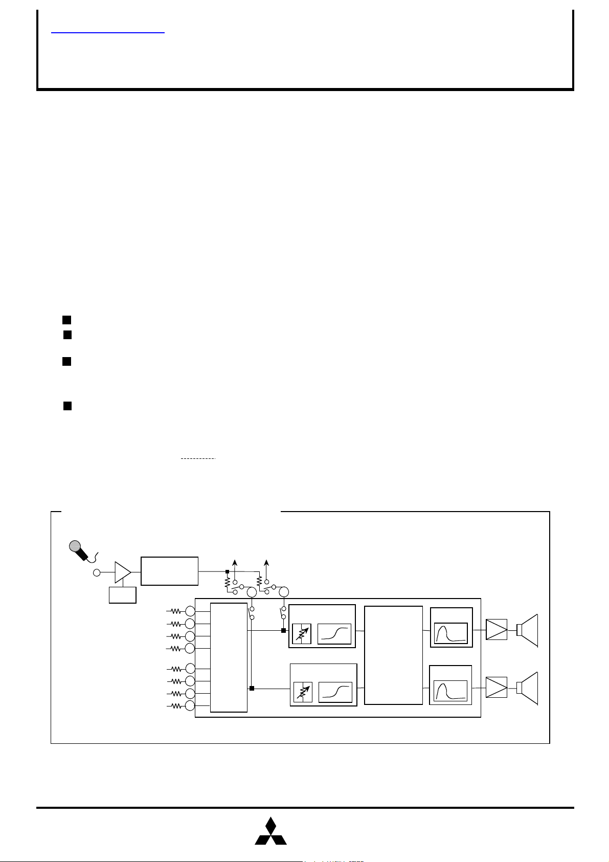
SYSTEM BLOCK DIAGRAM
查询M61515FP供应商
MITSUBISHI SOUND PROCESSORS ICs
PRELIMINARY
Notice : This is not a final specification.
some parametric limits are subject to change.
The M61515FP is the sound controller powered by "QSurround" system.
The "QSurround" system decodes and virtualizes multi-speaker surround
sound from various matrix surround encoded sources such as:
Dolby Surround, stereo downmixed AC-3, stereo downmixed DTS.
Produces normal and wide 3D sound expansion from any stereo
input signal.
(Note) This device is produced under license from QSound Lab,Inc.(Canada) .
Built-in "QSurround" sound technology
Electronic volume.
0 ~ -84dB, infinitesimal
2-band tone control
Bass(0 ~ +21dB/3dB STEP)
Treble(0 ~ +9dB/3dB STEP)
5 input selector(The fifth input can be used as REC OUT or MIC MIX.)
M61515FP
RECOMMENDED OPERATING CONDITIONS
Supply voltage range
MIC AMP
MIC
MIC
ALC
CH2 INPUT
CH1 INPUT
VOLUME
TAPE
TUNER
CD
TAPE
TUNER
CD
±2.25 ~ ±2.75V
REC OUT1
4-mode
selector
(stereo/
mono
REC OUT2
Electronic
Electronic
Treble
Treble
Bass
QSurround
Bass
MITSUBISHI
ELECTRIC
1
TONE CONTROL/VOLUME CONTROL
MITSUBISHI SOUND PROCESSORS ICs
PRELIMINARY
Notice : This is not a final specification.
some parametric limits are subject to change.
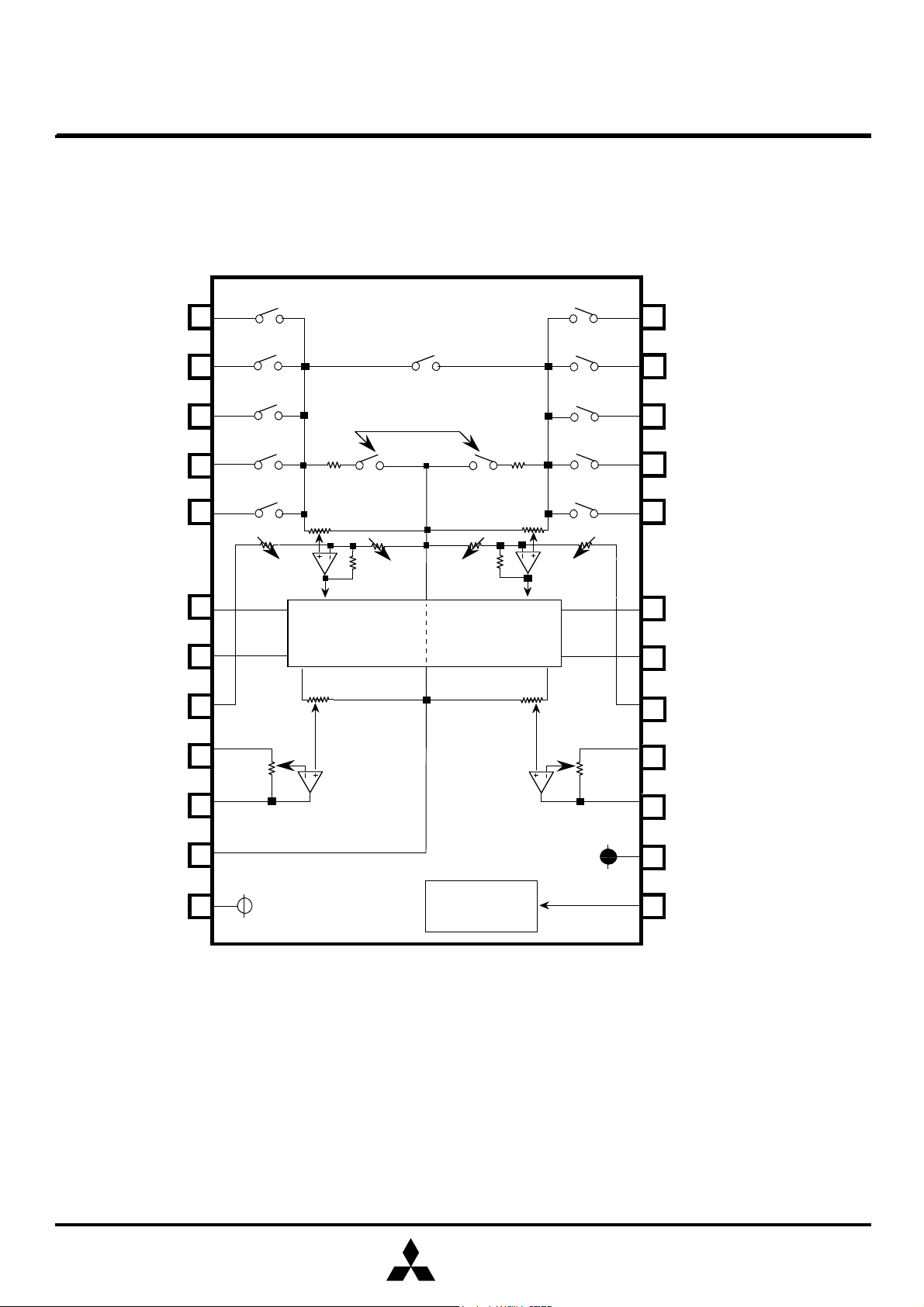
BLOCK DIAGRAM
INA1
INB1
INC1
IND1
INE1
1
Mono.SW
2
3
4
5
VOL
MUTE
VOL
24
23
22
21
20
M61515FP
INA2
INB2
INC2
IND2
INE2
QF1
QF2
TONEH1
TONEL1
OUT 1
GND
VDD
6
7
8
9
10
11
12
Treble
boost
QSurround
ATT ATT
Bass
boost
Control logic
Bass
boost
Treble
boost
19
18
17
16
15
14
13
QF4
QF3
TONEH2
TONEL2
OUT 2
VSS
CONT
MITSUBISHI
ELECTRIC
Units Resistance :Ω
Capacitance: F
2
TONE CONTROL/VOLUME CONTROL
MITSUBISHI SOUND PROCESSORS ICs
PRELIMINARY
Notice : This is not a final specification.
some parametric limits are subject to change.
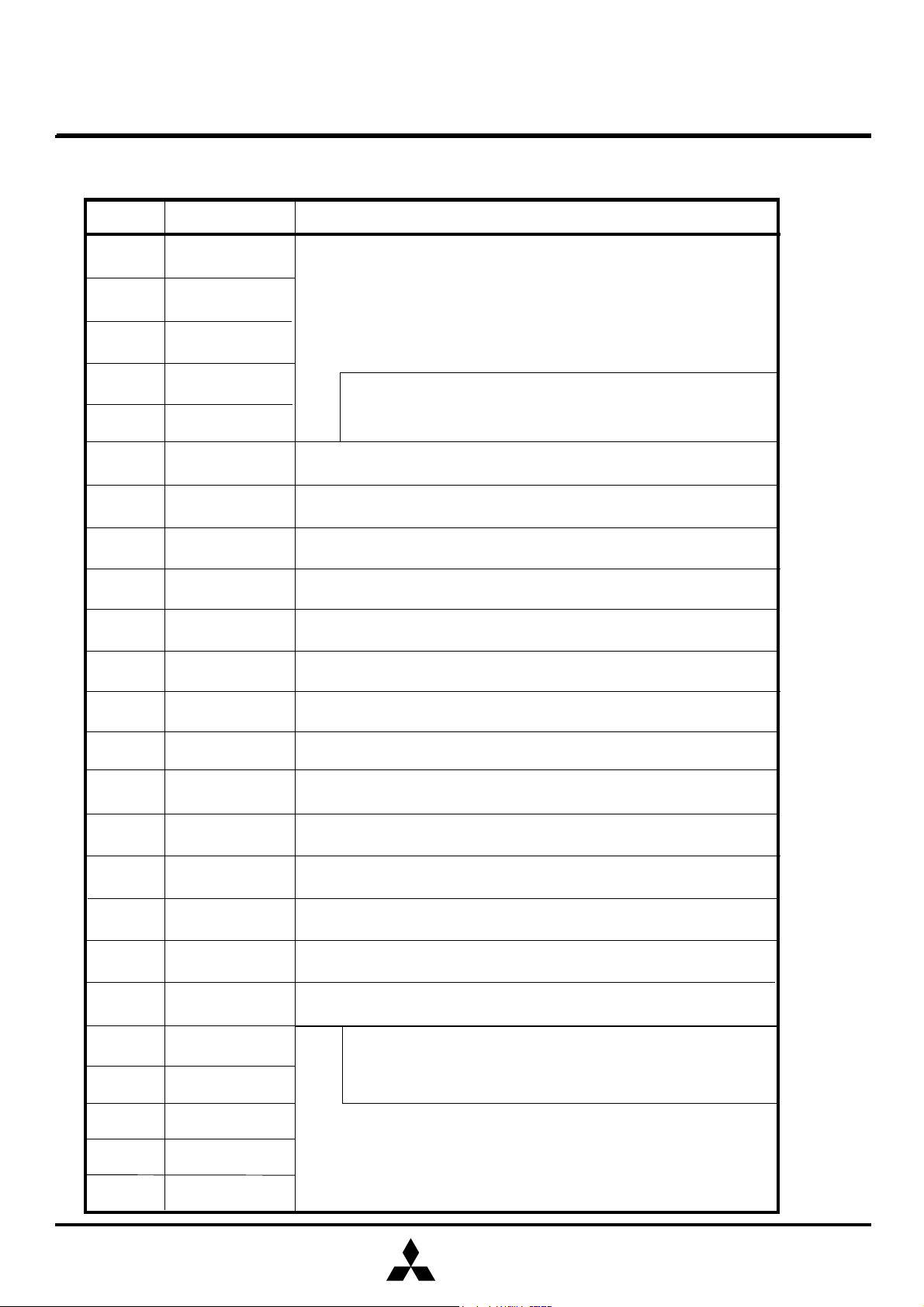
PIN DESCRIPTION
Pin No.
1
2
3
4
5
6
7
Name
IN A1
IN B1
IN C1
IN D1
IN E1
QF1
QF2
INPUTs of the channel 1
The switch of INE can be controlled independently.
Please set"ALL OFF"mode when the switch of E is only
ON.
QSurround filter 1
QSurround filter 2
M61515FP
Function
8
9
10
11
12
13
14
15
16
17
18
TONEH1
TONEL1
OUT1
GND
VDD
CONT
VSS
OUT2
TONEL2
TONEH2
QF3
Treble control adjustment of the channel 1
Bass control adjustment of the channel 1
OUTPUT of the channel 1
Ground
Supply voltage(+)
Control data input from a microcontroller
Supply voltage(-)
OUTPUT of the channel 2
Bass control adjustment of the channel 2
Treble control adjustment of the channel 2
QSurround filter 3
19
20
21
22
23
24
QF4
IN E2
IN D2
IN C2
IN B2
IN A2
QSurround filter 4
The switch of INE can be controlled independently.
Please set "ALL OFF" mode when the switch of E is only
ON.
INPUTs of the channel 2
MITSUBISHI
ELECTRIC
3
TONE CONTROL/VOLUME CONTROL
MITSUBISHI SOUND PROCESSORS ICs
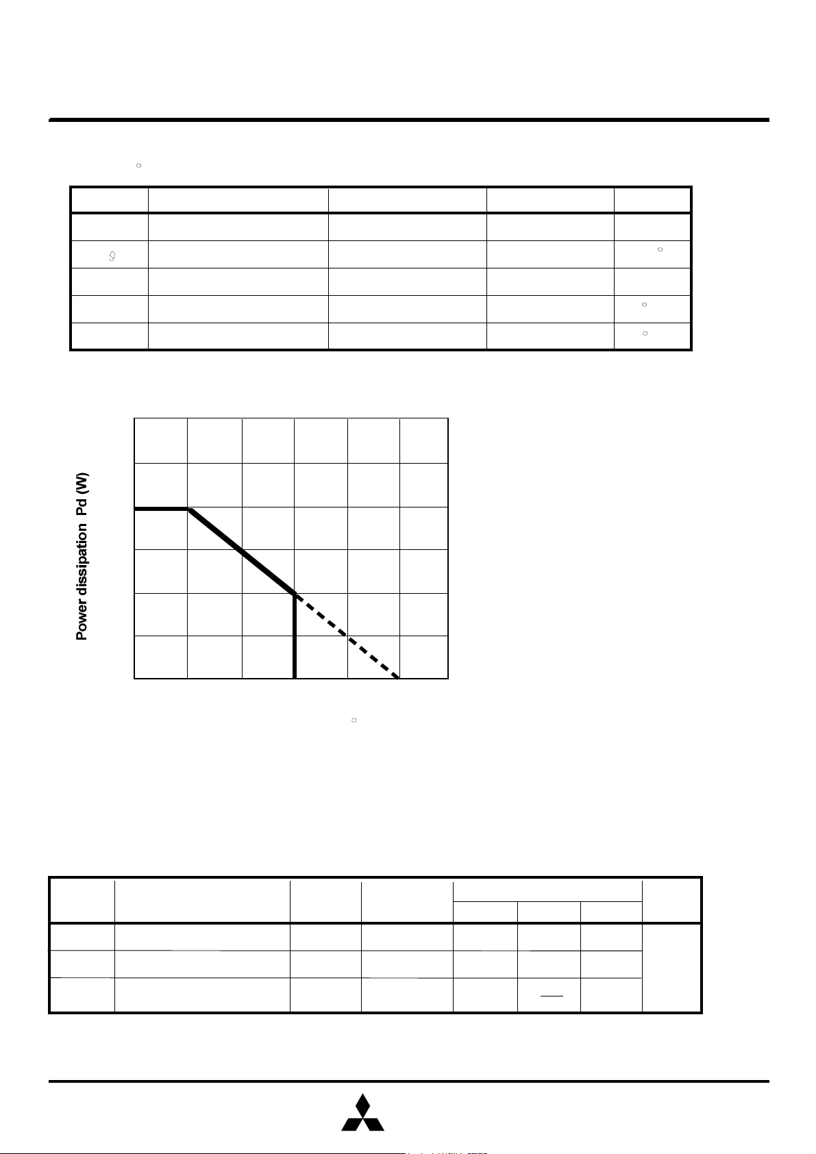
Recommended operating conditions
0
0.25
0.5
0.75
0255075100
125
150
(Ta=25 C,unless otherwise noted)
Ambient temperature Ta [
]
PRELIMINARY
Notice : This is not a final specification.
some parametric limits are subject to change.
ABSOLUTE MAXIMUM RATINGS
Symbol
VDD-VSS Supply voltage V
K
Pd
Topr
Tstg
Parameter
Thermal derating
Power dissipation
Operating temperature
Storage temperature
Test conditions
Note:1
Thermal derating(maximum rating)
Note.1 reference PC Board
Size :70mmX70mm
Thickness:1.6mm
Material :glass epoxy
Rating
6.0
5
500
-20 ~ 75
-40 ~ 125
M61515FP
Unit
mW/ C
mW
C
C
Symbol Parameter
Pin No.
C
Condition
Copper pattern dimension
Width :0.25mm
Length :25 ~ 30mm/lead
Thickness:18um
Limits
min.
typ.
max.
Unit
VDD Supply voltage(+)
VSS
CONT
Supply voltage(-)
Control data input voltage
12
14
13
-2.75
MITSUBISHI
ELECTRIC
2.25
GND
2.5
-2.5
2.75
-2.25
VDD
V
4

TONE CONTROL/VOLUME CONTROL
MITSUBISHI SOUND PROCESSORS ICs
ortWL
crWHWLCrf
STROBE)
(1) Wave form
L
WHtWH
(2) Voltage control signal
(3) Timing control signal
(4) Control signal example(Refer to page 6 on the control data)
WH
D02
D12
D22
D32
D42
D52
D62
D72
D82
D92
STROBE
D102
D112
D01
D11
D21
D31
D41
D51
D61
D71
D81
D91
STROBE
D101
D111
D121
D131
D122
D132
0V
2.5V
1.25V
PRELIMINARY
Notice : This is not a final specification.
some parametric limits are subject to change.
CONTROL SIGNALS SPECIFICATION
Threshold of the internal
DATA(H/L)
(CLOCK,
DATA,
H
M
0V
Threshold of
the internal CLOCK.
The internal DATA latch at the falling edges of this clock signal.
Digital input signal
Dn+0
DATA:L
Dn+1
1.25V
DATA:H
2.5V
Condition
Dn+10
Threshold of the internal
STROBE.
Dn+11
t
tr
tf
tr
Limits
min. typ. max.
M61515FP
t
tf
2.5V
t
tr
Unit
L signal
M signal
H signal
Symbol
t
t
t
t
t
Cycle time of digital signal
Pulse width of digital signal("H"level)
Pulse width of digital signal("L"level)
Rise time of digital signal
Fall time of digital signal
VDD=2.5V,VSS=-2.5V
L
VDD=2.5V,VSS=-2.5V
M
VDD=2.5V,VSS=-2.5V
H
Parameter
An example of the mode control
BYPASS/SURROUND SW:SURROUND
VOL/TREBLE SHARE AMP GAIN:20dB
INPUT :INA,
VOLUME :0dB
MUTE :OFF
max
0.4
0.4
0.4
1.5
VDD
Unit
µsec
GND
1.0
2.1
(VDD/2)
min
8
3.6
3.6
1.25
Limits
typ
SURROUND MODE:QSurround
SURROUND EFFECT:0dB
MODE:STEREO
BASS:18dB
TREBLE:6dB
RECOUT:ON(INE)
V
(MSB)
(GND)
MITSUBISHI
ELECTRIC
5

TONE CONTROL/VOLUME CONTROL
MITSUBISHI SOUND PROCESSORS ICs
(1) INPUT DATA
D61
D71
000
D81
D91
0
100010000
0
00100
101001110
0
00010
10010
0
101
011010001101011
0
011
1
111
100
00001
1
000
1
01001
11001
00101
10101
0110111
101
1
100000110000011
10011
010
1
1
11011
001111011
1
011111111
1
D101
CONTROL DATA FORMAT
(g)Treble amp gain
IN A to D all OFF
select(slot1)
Mode select
3:mono1+2
Treble(boost)
Bass(boost)
6:18dB, 7:21dB
CHIP/SLOT SELECT
MUTE
IN E
0:OFF
ON/OFF
ON/OFF
0:OFF
INPUT
3:IN D
Vol/Treble share amp
3:14dB
Surround mode
Surround effect
Bypass/
SW
(Valid in the surround mode.
Set 0dB at QSurround.)
CHIP/SLOT SELECT
select(slot1)
REAR Normal
surround
Normal surround
the infinitesimal
REAR Surround
PRELIMINARY
Notice : This is not a final specification.
some parametric limits are subject to change.
*It's necessary to set up the all control data after power on.
(MSB)
D01
Slot1
0
D02
Slot2
(a) Master volume
ATT
-0.0dB
-2.0dB
-4.0dB
-6.0dB
-8.0dB
-10.0dB
-12.0dB
-14.0dB
-16.0dB
-18.0dB
-20.0dB
-22.0dB
-24.0dB
-26.0dB
-28.0dB
-30.0dB
-32.0dB
-34.0dB
-36.0dB
-40.0dB
-44.0dB
-48.0dB
-52.0dB
-56.0dB
-60.0dB
-64.0dB
-68.0dB
-72.0dB
-76.0dB
-80.0dB
-84.0dB
SW
Gain SW
20dB
18dB
16dB
14dB
Input order
D11
Surround
D12 D42
D21 D31
gain SW
0:20dB
1:18dB
2:16dB
D22 D32
(h)Bypass/
Surround SW
D21 D31
0 0
0
1
0
1
1
1
Bypass/
Surround SW
Bypass
Surround
D41
D51
0:IN A
1:IN B
2:IN C
D52
0:stereo
1:mono1 only
2:mono2 only
D11
D61
D2 to D6:(a)Master volume
condition
D62
D71 D81 D91
D72 D82 D92
0:0dB, 1:3dB,
2:6dB, 3:9dB,
4:12dB, 5:15dB,
(b) Input select
Input select
IN A
IN B
IN C
IN D
IN A-D
select
*1) The input impedance is about 5k as input INE.
*2) INE can be controlled independently.
It can be used as Rec output.
(c)Mode control
Mode
stereo
mono1 only
mono2 only
mono1+2
(e)Bass control
Bass
0dB
3dB
6dB
9dB
12dB
15dB
18dB
21dB
(i)Surround mode
Mode
0
1
QSurround
0:0dB,1:3dB
2:6dB,3:9dB
IN E
off
IN E
on
D42
0 0
1
0
1
D62 D72
0 0
1
0
1
0
1
0
1 1
D02 D12
0 0
0
1
1
0
1
1
M61515FP
D101 D111
1:ON
(INPUT ALL
OFF)
D102 D112
1:ON
D41 D51
0
0
1
0
1
0
1
1
*
A: 0 0
B: 1 0
C: 0 1
D: 1 1
D52
*
(d)Treble control
Treble
0dB
0
1
1
3dB
6dB
9dB
(f)Chip/Slot control
D82
0
0
0
0
1
1
0
1
0
1
0
1
1
1
(j)Surround effect
Effect D22 D32
+3dB
0dB
-3dB
-6dB
D121 D131
0:select
1:no select
2:no select
3:no select
D122 D132
0:no select
1:no select
2:no select
3:select
D111
D112
0
1
0
Chip/Slot
no select
no select
0
1
*1
*2
1
D92 D102
0 0
0
1
0
1
1 1
D12* D13*
0 0
1
0
1
0 0
0
1
0
1
1
1
0
1
1
MITSUBISHI
ELECTRIC
6

TONE CONTROL/VOLUME CONTROL
MITSUBISHI SOUND PROCESSORS ICs
(2) NOTICE OF CONTROL DATA
VSS)<3.3V(TYP).
PRELIMINARY
Notice : This is not a final specification.
some parametric limits are subject to change.
1.Input only the control data at (1) INPUT DATA.
2.The interval of data transmission from the microcontroller is over
0.1 sec.This is waiting time for soft-switching to reduce the
shocknoise.
3.It's necessary to set up the all control data after power on,although the internal circuit is forced as below,when (VDD-
=
Parameter
Gain SW
Input select
Master volume
MUTE
Surround effect
Surround
Surround mode
Mode select
Bass
Treble
IN E
ON(Input ALLOFF)
M61515FP
Condition
18dB
ALL OFF
infinitesimal
- 6dB
OFF
QSurround
stereo
0dB
0dB
ON
MITSUBISHI
ELECTRIC
7

TONE CONTROL/VOLUME CONTROL
MITSUBISHI SOUND PROCESSORS ICs
Vrms
µVrms
µVrms
PRELIMINARY
M61515FP
Notice : This is not a final specification.
some parametric limits are subject to change.
ELECTRICAL CHARACTERISTICS
(VDD=2.5V,VSS=-2.5V,f=1kHz,Vi=100mV(rms),VOL=0dB,BASS=0dB,TREBLE=0dB,VOL/TREBLE
SHARE AMP=18dB,SURROUND=BYPASS,RL=10K,Ta=25 C,unless otherwise noted)
Limits
Symbol
IDD
ISS
Gv1
Gv2
Vomax
Parameter
Circuit current of
positive power supply
Circuit current of
negative power supply
Voltage gain
(selector)
Voltage gain
(tone control)
Maximum output voltage
Condition
Quiescent
Quiescent
Vol/Treble share amp gain=18dB
Bypass
Vol/Treble share amp gain=18dB
QSurround mode Vi=20mVrms
RL=10k,THD=1%
min.
25.5 29.5
1.2
typ.
30
-30
27.5
1.6
max.
45
-45
201816
Unit
mA
mA
dB
dB
THD
No1
No2
ATTmax
GB1
GB2
GB3
GB4
GB5
GB6
GB7
GT1
GT2
GT3
Total harmonic distortion
Output noise voltage
Maximum attenuation
Bass boost
Treble boost
BW=400 ~ 30kHz
JIS-A,Rg=5.1k,VOL=the infinitesimal
BYPASS
JIS-A,Rg=5.1k,VOL=
QSurround mode
Output referencelevel(Vo=1Vrms),
ATT=
the infinitesimal,JIS-A
3dB
6dB
9dB
12dB
15dB
18dB
21dB
3dB
6dB
9dB
f=1kHz,
Vo=80mVrms
f=1kHz,
Vo=80mVrms
the infinitesimal
0.02
11
-95 dB
1.5
4.5
7.5
10.5
13.5 16.5
1.5 4.5
12
15
1816.5 19.5
2119.5 22.5
0.08
6
3
6
9
3
64.5
9 10.57.5
15
30
-90
4.5
7.5
10.5
13.5
7.5
%
dB
MITSUBISHI
ELECTRIC
8

TONE CONTROL/VOLUME CONTROL
MITSUBISHI SOUND PROCESSORS ICs
(1) Equivalent circuit of the bass boost
(k)
Bass boost
Treble boost
Resistor
PRELIMINARY
Notice : This is not a final specification.
some parametric limits are subject to change.
FUNCTION DESCRIPTION
IN
R3
9,16
TONEL
C1
R2
10,15
OUT
C2
R1
Fo=
2
.
.
Q=
C1+C2
(C1=C2)
Gv=20log
R2,R3 (typical)
3dB 6dB 9dB
R2
15.4
1
R1(R2+R3)C1C2
1
C1C2R2
R1
R2+R3
R1
R3
R1
12dB
25.7
32.9
38.7
M61515FP
+2
(dB)
+2
15dB 18dB
41.6
44.2
(Hz)
21dB
(2) Equivalent circuit of the treble boost
IN
R3
R1
R2
8,17
TONEH
C1
OUT
R2 (typical)
R2 (k)
R3
30.6
.
.
Fc=
Gv=20log
Zc=
20.3
13.1
7.3
1
.
.
2 R2 C1
R1+ (R2+Zc)//R3
(R2+Zc)//R3
1
(ohm)
j C1
3dB 6dB 9dB
5.3 2.2
1.2
4.4
(Hz)
1.8460
(dB)
R1,R3 (typical)
Gain
R1 (k)
R3 (k)
MITSUBISHI
ELECTRIC
14dB
10.8813.6517.21
2.72 2.57
16dB
18dB
2.48
20dB
21.60
2.40
9

TONE CONTROL/VOLUME CONTROL
MITSUBISHI SOUND PROCESSORS ICs
OUT1
0.033u
0.033u
0.22u
0.22u
0.22u
PRELIMINARY
Notice : This is not a final specification.
some parametric limits are subject to change.
APPLICATION EXAMPLE
INA1
INB1
INC1
IND1
INE1
0.01u
1
2
3
4
5
Treble
boost
VOL
6
QSurround
7
Mono.SW
MUTE
VOL
Treble
boost
M61515FP
24
23
22
21
20
19
18
INA2
INB2
INC2
IND2
INE2
0.01u
2.2K
VDD=2.5V
10
11
12
8
ATT ATT
9
Bass
boost
Bass
boost
17
16
15
2.2K
0.22u
OUT2
14
VSS= -2.5V
Control logic
13
MITSUBISHI
ELECTRIC
Units
Resistor : Ω
Capacitor: F
10

TONE CONTROL/VOLUME CONTROL
MITSUBISHI SOUND PROCESSORS ICs
PRELIMINARY
Notice : This is not a final specification.
some parametric limits are subject to change.
OUTLINE
M61515FP
MITSUBISHI
ELECTRIC
11
 Loading...