

Mitsubishi Lancer Evolution X 2012 Owner's Manual
LANCER
EVOLUTION
OWNER’S MANUAL
LANCER EVOLUTION - ENGLISH - OGEE12E1
LANCER EVOLUTION - ENGLISH - OGEE12E1
Foreword
E09200104018
Thank you for selecting a LANCER EVOLUTION as your new vehicle.
This owner’s manual will add to your understanding and full enjoyment of
the many fine features of this vehicle.
It contains information prepared to acquaint you with the proper way to operate and maintain your vehicle for the utmost in driving pleasure.
MITSUBISHI MOTORS Europe B.V. reserves the right to make changes in
design and specifications and/or to make additions to or improvements in
this product without obligation to install them on products previously manufactured.
It is an absolute requirement for the driver to strictly observe all laws and regulations concerning vehicles.
This owner’s manual has been written in compliance with such laws and regulations, but some of the contents may become contradictory with later amendment of the laws and regulations.
Please leave this owner’s manual in this vehicle at time of resale. The next
owner will appreciate having access to the information contained in this owner’s manual.
Repairs to your vehicle:
Vehicles in the warranty period:
All warranty repairs must be carried out by a MITSUBISHI MOTORS Authorized Service Point.
Vehicles outside the warranty period:
Where the vehicle is repaired is at the discretion of the owner.
Throughout this owner’s manual the words WARNING and CAUTION ap-
pear.
These serve as reminders to be especially careful. Failure to follow instructions could result in personal injury or damage to your vehicle.
WARNING
indicates a strong possibility of severe personal injury or death if instructions are not followed.
CAUTION
means hazards or unsafe practices that could cause minor personal injury or damage to your vehicle.
You will see another important symbol:
NOTE: gives helpful information.
*: indicates optional equipment.
It may differ according to the sales classification; refer
to the sales catalogue.
Abbreviations used in this owner’s manual:
LHD: Left-Hand Drive
RHD: Right-Hand Drive
M/T: Manual Transmission
Information for station service
E09300101630
Fuel
Fuel tank capacity 55 litres
Fuel requirements
Unleaded petrol octane number (EN228) 98 RON or higher
Refer to the “General information” section for the fuel selection.
Engine oil Refer to the “Maintenance” section for the selection of engine oil.
Tyre inflation pressure Refer to the “Maintenance” section for the tyre inflation pressure.
© 2011 Mitsubishi Motors Corporation
12
OGEE12E1
BLC11.001029
Table of contents
OGEE12E1
Overview
General information
Locking and unlocking 1
Seat and seat belts 2
Instruments and controls 3
Starting and driving 4
For pleasant driving 5
For emergencies 6
Vehicle care 7
Maintenance 8
Specifications 9

LHD
1
2
3
4
6
5
7
8
9
10
11
12
13
14
15 16
Overview
OGEE12E1
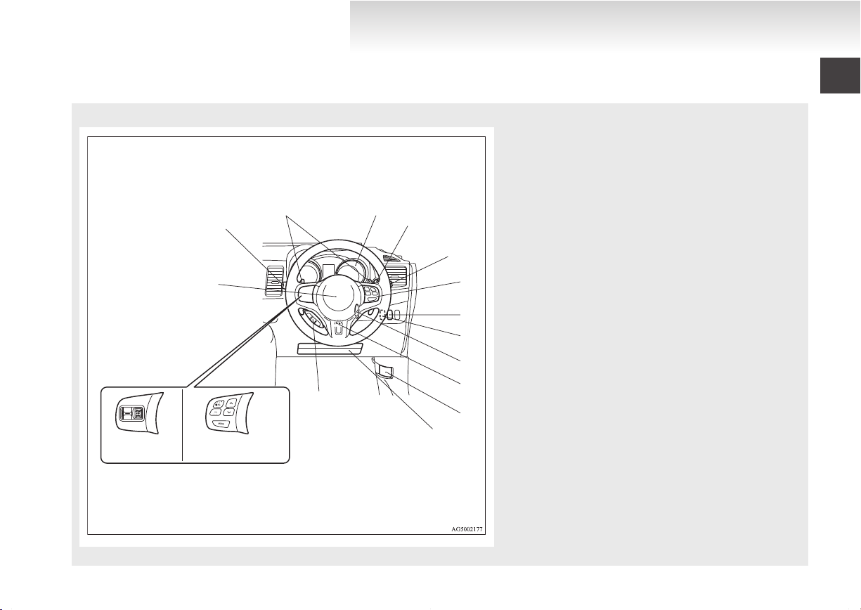
Instruments and Controls (Driver’s area)
1. Multi-information meter switch p. 3-05
2.
Instruments p. 3-02
3. Shift paddles* p. 4-21, 4-22
4. Wiper and washer switch p. 3-45
5. Cruise control switches* p. 4-38
6. Ignition switch p. 1-11, 1-16, 4-09
7. Supplemental restraint system - airbag (for driver’s seat) p. 2-18,
2-22
Horn switch p. 3-49
8. Steering wheel height adjustment lever p. 4-06
9. Supplemental restraint system - driver’s knee airbag p. 2-23
10. Bluetooth® 2.0 interface* p. 5-64
11. Bonnet release lever p. 8-03
12. Fuses p. 8-16
13. ASC OFF switch p. 4-34
14. Combination headlamps and dipper switch p. 3-37
Turn-signal lever p. 3-41
Front fog lamp switch p. 3-44
Rear fog lamp switch p. 3-44
Headlamp washer switch p. 3-48
15. AWC switch* p. 4-29
16. Steering wheel audio remote control switches* p. 5-53
E00100106425
1
RHD
2
3
4
5
6
7
8
9
10
11
12
1516
13
14
OGEE12E1
Overview
1. Shift paddles* p. 4-21, 4-22
2.
Instruments p. 3-02
3. Multi-information meter switch p. 3-05
4. Wiper and washer switch p. 3-45
5. Cruise control switches* p. 4-38
6. ASC OFF switch p. 4-34
7. Trunk lid opener switch p. 1-27
8. Ignition switch p. 1-11, 1-16, 4-09
9. Steering wheel height adjustment lever p. 4-06
10. Bonnet release lever p. 8-03
11. Supplemental restraint system - driver’s knee airbag p. 2-23
12. Bluetooth® 2.0 interface* p. 5-64
13. Supplemental restraint system - airbag (for driver’s seat) p. 2-18,
2-22
Horn switch p. 3-49
14. Combination headlamps and dipper switch p. 3-37
Turn-signal lever p. 3-41
Front fog lamp switch p. 3-44
Rear fog lamp switch p. 3-44
Headlamp washer switch p. 3-48
15. Steering wheel audio remote control switches* p. 5-53
16. AWC switch* p. 4-29
LHD
1
2
3
4
5
7
6
8
9
10
11
12
13
14
Overview
OGEE12E1
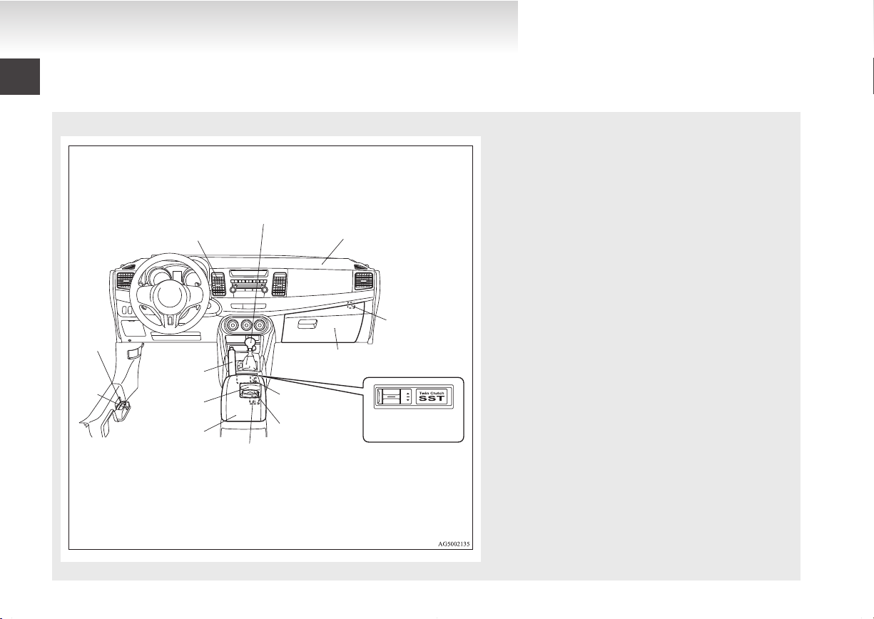
Instruments and Controls (Instrument panel)
E00100106438
1. Ventilators p. 5-02
2.
Gearshift lever p. 4-15, 4-17
3. Supplemental restraint system - airbag (for front passenger’s
seat) p. 2-18, 2-22
4. Front passenger’s airbag ON-OFF switch p. 2-18, 2-21
5. Glove box p. 5-87
USB input terminal* p. 5-80
6. Twin Clutch SST control mode switch* p. 4-20
7. AWC switch* p. 4-29
8. Moveable ashtray* p. 5-83
9. Heated seat switch* p. 2-04
10. Floor console box p. 5-88
11. Cup holder p. 5-88
12. Parking brake lever p. 4-04
13. Fuel tank filler door release lever p. 02
14. Trunk lid release lever p. 1-27
RHD
1
2
3
4
5
6
7
8
9
10
11
12
13
14
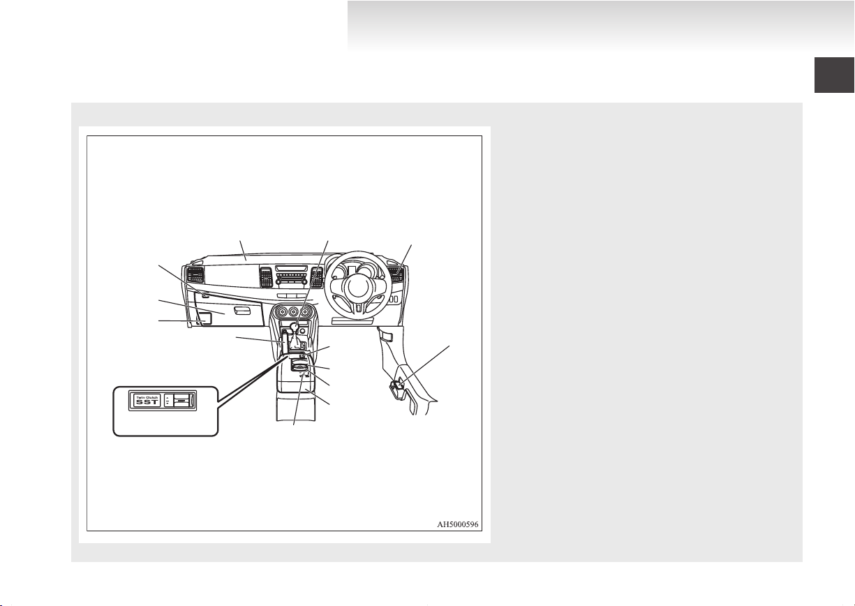
OGEE12E1
Overview
1. Supplemental restraint system - airbag (for front passenger’s
seat) p. 2-18, 2-22
2.
Gearshift lever p. 4-15, 4-17
3. Ventilators p. 5-02
4. Fuel tank filler door release lever p. 02
5. AWC switch* p. 4-29
6. Cup holder p. 5-88
7. Moveable ashtray* p. 5-83
8. Floor console box p. 5-88
9. Heated seat switch* p. 2-04
10. Twin Clutch SST control mode switch* p. 4-20
11. Parking brake lever p. 4-04
12. Fuses p. 8-16
13. Glove box p. 5-87
USB input terminal* p. 5-80
14. Front passenger’s airbag ON-OFF switch p. 2-18, 2-21
1
2
3
4
5
6
7
8
9
10
Overview
OGEE12E1
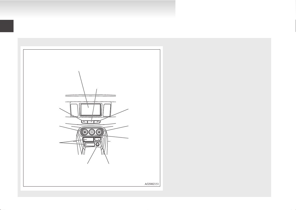
Centre panel
E00100600428
1. Audio* p. 5-09, 5-24
Digital clock*
p. 5-62
MITSUBISHI Multi-Communication System*
Refer to the separate “MITSUBISHI Multi-Communication System owner’s manual”
2. Hazard warning flasher switch p. 3-43
3. Front passenger seat belt warning lamp p. 2-08
4. Rear window demister switch (LHD vehicles) p. 3-48
5. Air conditioning p. 5-04
6. Auxiliary Audio connector (RCA)* p. 5-52
Auxiliary Video connector (RCA)* p. 5-52
7. Cigarette lighter* p. 5-83
Accessory socket* p. 5-84
8. Front console box p. 5-87
9. Rear window demister switch (RHD vehicles) p. 3-48
10. Front passenger’s airbag OFF indication lamp p. 2-18, 2-21

LHD
1
2
3
4
5
6
7
8
9
10
11
12
13
14
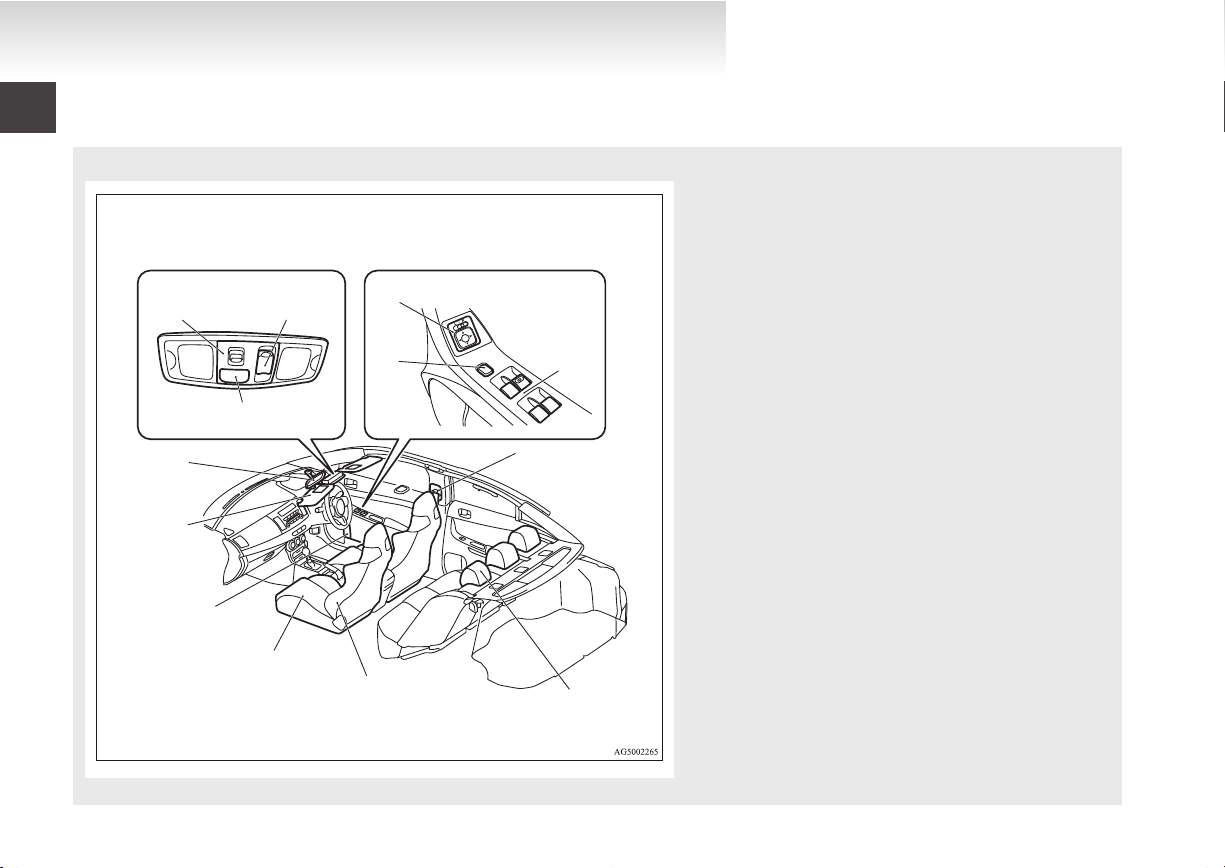
Overview
OGEE12E1
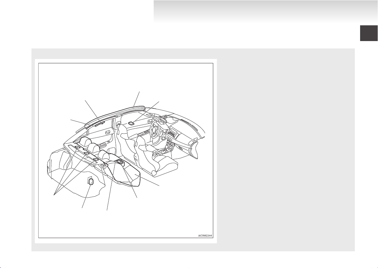
Interior
E00100204552
1. Adjustable seat belt anchor (front seats) p. 2-08
Seat belts p. 2-06
2.
Inside rear-view mirror p. 4-06, 4-46
3. Sun visors p. 5-82
Vanity mirror p. 5-82
Card holder p. 5-82
4. Bottle holder (for front seats) p. 5-89
5. Front seats p. 2-03
6. Supplemental restraint system - side airbag (for front
seats) p. 2-25
7. Head restraints p. 2-05
8. Electric window control switches p. 1-35
9. Lock switch p. 1-35
10. Electric remote-controlled outside rear-view mirrors
switch p. 4-07
11. Central door lock switch p. 1-23
12. Front room & map lamp p. 5-84, 8-22, 8-27
13. Sunroof switch* p. 1-37
14. Bluetooth® 2.0 interface* p. 5-64
RHD
1
2
3
4
5
6
7
8
9
10
11
12
13
OGEE12E1
Overview
1. Inside rear-view mirror p. 4-06, 4-46
2.
Adjustable seat belt anchor (front seats) p. 2-08
Seat belts p. 2-06
3. Head restraints p. 2-05
4. Supplemental restraint system - side airbag (for front
seats) p. 2-25
5. Front seats p. 2-03
6. Bottle holder (for front seats) p. 5-89
7. Sun visors p. 5-82
Vanity mirror p. 5-82
Card holder p. 5-82
8. Front room & map lamp p. 5-84, 8-22, 8-27
9. Sunroof switch* p. 1-37
10. Bluetooth® 2.0 interface* p. 5-64
11. Electric remote-controlled outside rear-view mirrors
switch p. 4-07
12. Electric window control switches p. 1-35
13. Lock switch p. 1-35
LHD
1
2
3
4
5
6
7
8
9
Overview
OGEE12E1
Interior
E00100204129
1. Assist grip p. 5-89
2.
Coat hook p. 5-90
3. Supplemental restraint system - curtain airbag p. 2-26
4. Rear room lamp* p. 5-85, 8-22, 8-28
5. Rear seat p. 2-05
6. Cup holder p. 5-89
7. Armrest p. 2-05
8. AWC control fluid tank p. 8-06, 9-11
9. Tether anchorages for child restraint system p. 2-16

RHD
1
2
3
4
5
6
7
8
9
OGEE12E1
Overview
1. Rear room lamp* p. 5-85, 8-22, 8-28
2.
Supplemental restraint system - curtain airbag p. 2-26
3. Coat hook p. 5-90
4. Assist grip p. 5-89
5. AWC control fluid tank p. 8-06, 9-11
6. Tether anchorages for child restraint system p. 2-16
7. Armrest p. 2-05
8. Cup holder p. 5-89
9. Rear seat p. 2-05
1 2
3
4
5
6
Overview
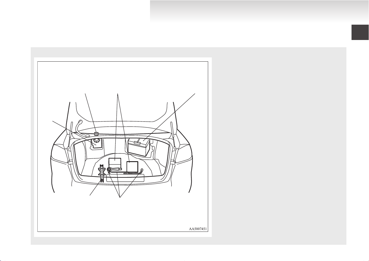
OGEE12E1
Trunk area (Except for vehicle with spare wheel)
1. Trunk room lamp p. 8-22, 8-29
2.
Tyre repair kit p. 6-05
3. Battery p. 6-02, 8-08
4. Tools p. 6-06
5. Jack p. 6-06
6. Front washer fluid reservoir p. 8-07
E00100300467
1
2
3
4
5
6
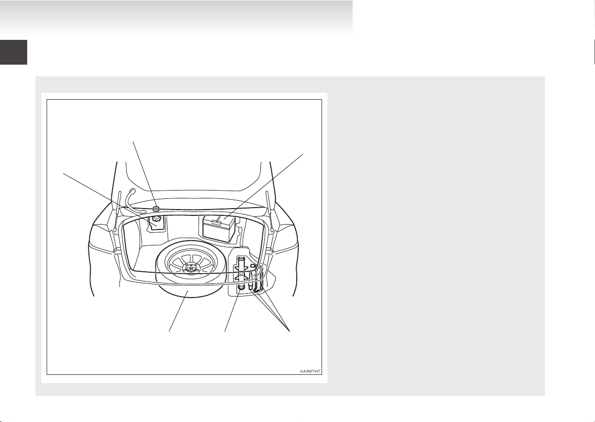
Overview
OGEE12E1
Trunk area (Vehicle with full size spare wheel)
E00100300470
1. Trunk room lamp p. 8-22, 8-29
2.
Battery p. 6-02, 8-08
3. Tools p. 6-06
4. Jack p. 6-06
5. Spare wheel p. 6-12, 6-13
6. Front washer fluid reservoir p. 8-07
1
2
3
4
5
6
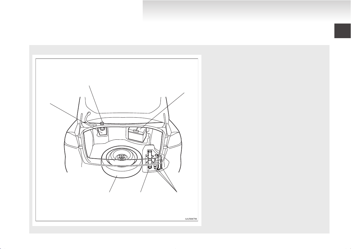
Overview
OGEE12E1
Trunk area (Vehicle with compact spare wheel)
E00100300483
1. Trunk room lamp p. 8-22, 8-29
2.
Battery p. 6-02, 8-08
3. Tools p. 6-06
4. Jack p. 6-06
5. Spare wheel p. 6-12, 6-13
6. Front washer fluid reservoir p. 8-07
1
2
3
4
5
6
7
8
9
Overview
OGEE12E1
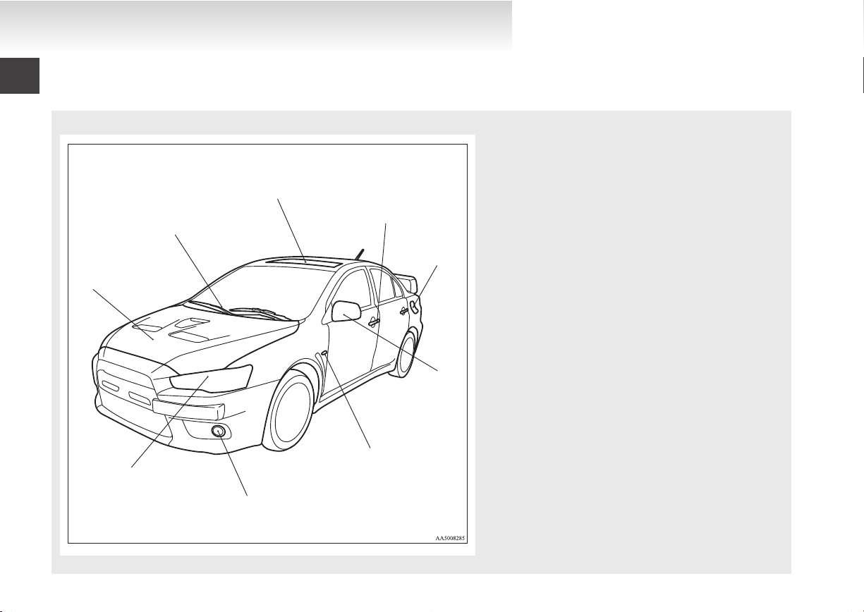
Outside (Front)
E00100504076
1. Bonnet p. 8-03
2.
Windscreen wipers and washer p. 3-45, 8-14
3. Sunroof* p. 1-37
4. Keyless entry system* p. 1-04
Keyless operation system* p. 1-07
Locking and unlocking p. 1-22
5. Fuel tank filler p. 02
6. Outside rear-view mirrors p. 4-07
7. Side turn-signal lamps p. 3-41, 8-22
8. Front fog lamps p. 3-44, 8-22, 8-25
9. Headlamps, high/low beam p. 3-37, 8-22, 8-22
Front turn-signal lamps p. 3-41, 8-22, 8-24
Position lamps p. 3-37, 8-22, 8-24
Bending lamps (Adaptive Front lighting System (AFS)) p. 3-42,
8-22, 8-23
1
2
3
4
5
6
7
8
9
10
11
Overview
OGEE12E1
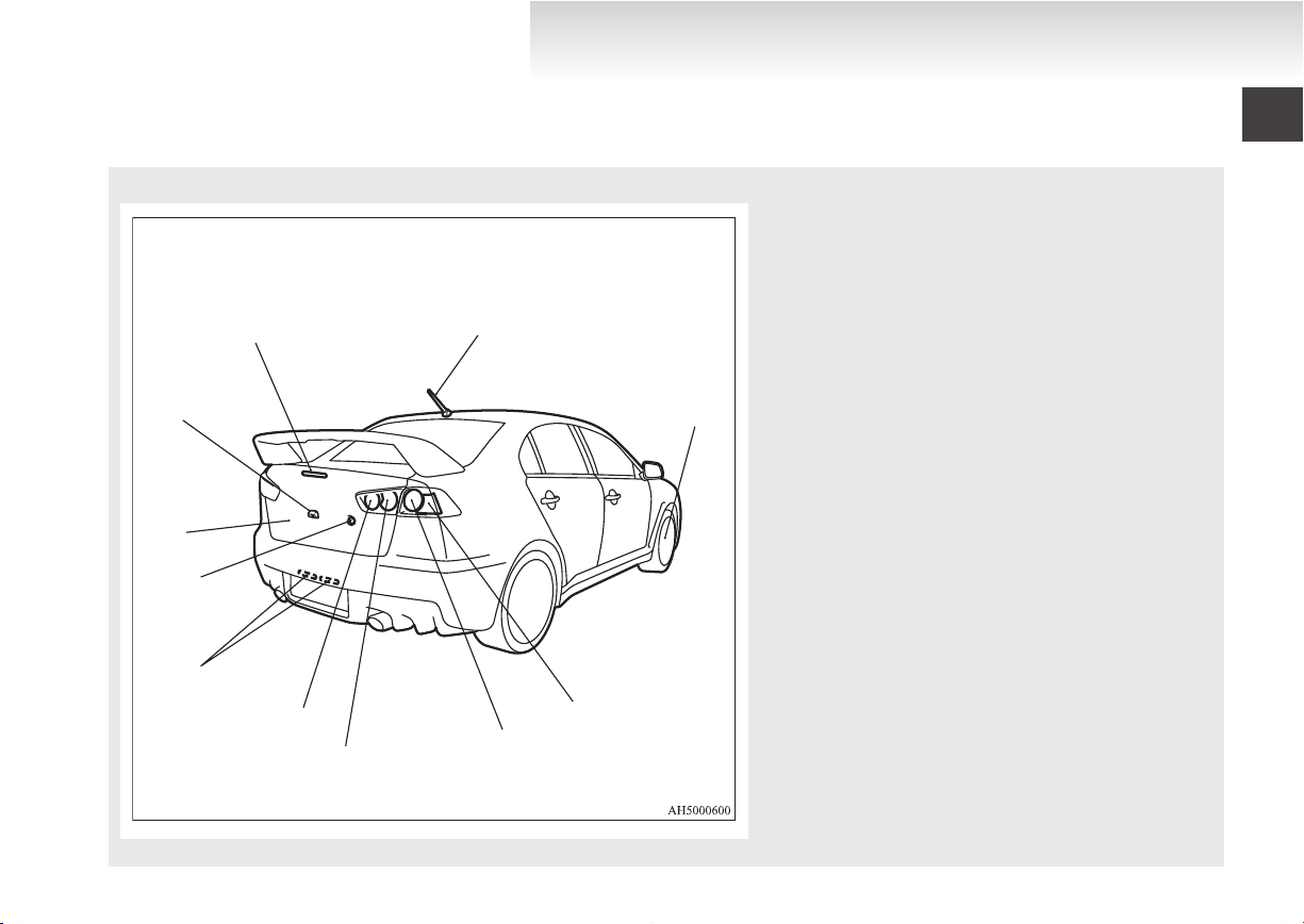
Outside (Rear)
1. Rear-view camera* p. 4-43
2.
High-mounted stop lamp p. 8-22
3. Antenna p. 5-61
4. Tyre inflation pressures p. 8-10
Changing tyres p. 6-12
Tyre rotation p. 8-11
Tyre chains p. 8-12
5. Rear turn-signal lamps p. 3-41, 8-22, 8-26
6. Tail and stop lamps p. 3-37, 8-22, 8-26
7. Tail lamps p. 3-37, 8-22, 8-26
8. Reversing lamp (Passenger’s side only) p. 8-22, 8-26
Rear fog lamp (Driver’s side only) p. 3-44, 8-22, 8-26
9. Licence plate lamps p. 3-37, 8-22, 8-27
10. Trunk lid OPEN switch* p. 1-09
11. Trunk lid p. 1-27
E00100505174

OGEE12E1

General information
OGEE12E1
Fuel selection...................................................................................02
Filling the fuel tank..........................................................................02
Installation of accessories................................................................04
Modification/alterations to the electrical or fuel systems................04
Genuine parts...................................................................................05
Used engine oils safety instructions and disposal infor-
mation..........................................................................................05
Disposal information for used batteries...........................................05

General information
OGEE12E1
Fuel selection
Recommended
fuel
Your engine is designed to provide satisfactory performance by using unleaded petrol octane number
98 RON or higher. In order to maintain engine performance and exhaust system durability, use unleaded petrol octane number 98 RON or higher.
Unleaded petrol octane number (EN228)
98 RON or higher
E00200102617
CAUTION
use of leaded fuel can result in seri-
The
l
ous damage to the engine and catalytic
converter. Do not use the leaded fuel.
NOTE
Your
vehicles have the knock control system
l
so that you can use unleaded petrol 95 RON
as an emergent measure in case unleaded petrol 98 RON or higher is not available on journey, etc. In such a case, you don’t need to adjust the engine specially.
In case of using unleaded petrol 95 RON, the
engine performance level is reduced.
Repeatedly
l
speeds can cause deposits to form in the fuel
system and engine, resulting in poor starting
and poor acceleration. If these problems occur, you are advised to add a detergent additive to the gasoline when you refuel the vehicle. The additive will remove the deposits,
thereby returning the engine to a normal condition. Be sure to use a genuine
MITSUBISHI FUEL SYSTEM CLEANER.
Using an unsuitable additive could make the
engine malfunction. For details, please contact your MITSUBISHI MOTORS Authorized Service Point.
Poor quality petrol can cause problems such
l
as hard starting, stalling, engine noise and hesitation. If your experience these problems,
try another brand and/or grade of petrol.
If the check engine warning lamp flashes,
have the system checked as soon as possible
at a MITSUBISHI MOTORS Authorized
Service Point.
E10 type petrol
The petrol engines are compatible with the E10
type
petrol (containing 10 % ethanol) conforming
to European standards EN 228.
driving short distance at low
E00203200019
CAUTION
Do not use more than
l
of ethanol (grain alcohol) by volume.
Use of more than 10 % concentration
may lead to damage to your vehicle fuel
system, engine, engine sensors and exhaust system.
10 % concentration
Filling the fuel tank
WARNING
handling fuel, comply with the safe-
When
l
ty regulations displayed by garages and
filling stations.
Before removing the fuel cap, be sure to
l
get rid of your body’s static electricity by
touching a metal part of either the car or
the fuel pump. Any static electricity on
your body could create a spark that ignites fuel vapour.
Perform the whole refueling process
l
(opening the fuel tank filler door, removing the fuel cap, etc.) by yourself. Do not
let any other person come near the fuel
tank filler. If you allowed a person to
help you and that person was carrying
static electricity, fuel vapour could be ignited.
Do not move away from the fuel tank fill-
l
er until refueling is finished. If you
moved away and did something else (for
example, cleaning your windscreen) partway through the refueling process, you
could pick up a fresh charge of static electricity.
If the tank cap must be replaced, use only
l
a MITSUBISHI MOTORS original part.
Fuel tank capacity
55 litres
Refueling
1.
Before filling with fuel, stop the engine.
E00200202100
02
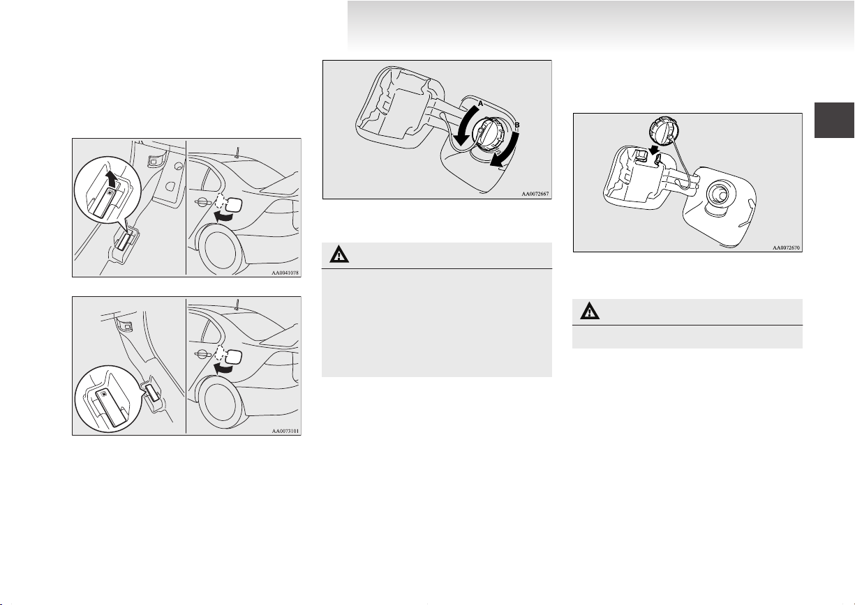
2. The fuel tank filler is located on the rear left
LHD
RHD
OGEE12E1
side of your vehicle.
Open the fuel tank filler door with the release lever located on the side of the driver’s
seat.
A- Remove
B- Close
CAUTION
the fuel system may be under pres-
Since
l
sure, remove the fuel tank filler tube cap
slowly. This relieves any pressure or vacuum that might have built up in the fuel
tank. If you hear a hissing sound, wait until it stops before removing the cap. Otherwise, fuel may spray out, injuring you
or others.
General information
4. While
5. Insert
filling with fuel, store the cap in the
capholder located on the inside of the fuel
tank filler door.
the gun in the tank port as far as it goes.
CAUTION
Do not tilt the gun.
l
6. When
the gun stops automatically, do not fill
with fuel any more.
7. To close, turn the fuel tank filler tube cap
slowly clockwise until you hear clicking
sounds, then gently push the fuel tank filler
door closed.
the fuel tank filler tube by slowly turn-
3. Open
ing the cap anticlockwise.
03
General information
OGEE12E1
Installation of accessories
recommend you to consult your MITSUBISHI
We
MOTORS Authorized Service Point.
The installation of accessories, optional
l
parts, should only be carried out within the
limits prescribed by law in your country, and
in accordance with the guidelines fitting instructions and warnings contained within the
documents accompanying the parts or accessories.
Improper installation of electrical compo-
l
nents may cause an electrical fire if incorrectly fitted. Please refer to the Modification/alteration to the electrical or fuel systems section within this owner’s manual.
Using a cellular phone or radio set inside the
l
vehicle without an external antenna may
cause electrical system interference, which
could lead to unsafe vehicle operation.
Tyres and wheels which do not meet specifi-
l
cations must not be used.
Refer to the “Specifications” section for information regarding wheel and tyre sizes.
E00200300703
Important points!
Due to large number of accessory and replacement
parts of different manufactures available in the market, it is not possible, not only for MITSUBISHI
MOTORS, but also a MITSUBISHI MOTORS Authorized Service Point, to check whether the attachment or installation of such parts affects the overall
safety of your MITSUBISHI-vehicle.
Even when such parts are officially authorized, for
example
praisal for the part) or through the execution of the
part in an officially approved manner of construction, or when a single operation permit following
the attachment or installation of such parts, it cannot be deduced from that alone, that the driving safety of your vehicles has not been affected.
Consider also that there basically exists no liability
on the part of the appraiser or the official. Only in
the case of parts (MITSUBISHI MOTORS original
replacement or exchange parts as well as
MITSUBISHI MOTORS genuine accessories) that
are recommended and released by a MITSUBISHI
MOTORS Authorized Service Point and that are attached or installed by a MITSUBISHI MOTORS
Authorized Service Point can you assume, that optimal safety has been provided. The same also pertains to modifications of MITSUBISHI vehicle
with respect to the production specifications. For
your own safety, in such cases, you should only undertake modifications according to the recommendations of a MITSUBISHI MOTORS Authorized
Service Point.
by a “general operators permit” (an ap-
Modification/alterations to the
electrical or fuel systems
MITSUBISHI MOTORS
safe, high quality vehicles. In order to maintain this
safety and quality, it is important that any accessory that is to be fitted, or any modifications carried
out which involve the electrical or fuel systems,
should be carried out in accordance with
MITSUBISHI MOTORS guidelines.
has always manufactured
E00200400195
CAUTION
the wiring interferes with any part of
If
l
the vehicle bodywork or improper installation methods are used, i.e. protective
fuses not installed, etc.), electronic devices may be adversely affected, possibly resulting in an electrical fire or other failures that may cause an accident.
04
General information
OGEE12E1
Genuine parts
MITSUBISHI MOTORS
to bring you a superbly crafted automobile offering
the highest quality and dependability.
Use MITSUBISHI MOTORS Genuine Parts, designed and manufactured to maintain your
MITSUBISHI MOTORS automobile at top performance. MITSUBISHI MOTORS Genuine Parts
are identified by this mark and are available at all
MITSUBISHI MOTORS Authorized Service
Points.
has gone to great lengths
E00200500545
Used engine oils safety
instructions and disposal
information
E00200600025
WARNING
Prolonged
l
cause serious skin disorders, including
dermatitis and cancer.
Avoid contact with the skin as far as pos-
l
sible and wash thoroughly after any contact.
Keep used engine oils out of reach of chil-
l
dren.
Protect the environment
It
is illegal to pollute drains, water courses and soil.
Use authorized waste collection facilities, including civic amenity sites and garages providing facilities for disposal of used oil and used oil filters. If in
doubt, contact your local authority for advice on disposal.
and repeated contact may
Disposal information for used
batteries
Your vehicle contains batteries
and/or accumulators.
Do
not be mixed with general
household waste.
For proper treatment, recovery
and recycling of used batteries,
please take them to applicable collection points, in accordance
with your national legislation
and the Directives 2006/66/EC.
By disposing of these batteries
correctly, you will help to save
valuable resources and prevent
any potential negative effects on
human health and the environment which could otherwise
arise from inappropriate waste
handling.
E00201300016
05

OGEE12E1

Locking and unlocking
OGEE12E1
Keys..............................................................................................1-02
Electronic immobilizer (Anti-theft starting system).....................1-03
Keyless entry system*..................................................................1-04
Keyless operation system*...........................................................1-07
Doors............................................................................................1-22
Central door locks.........................................................................1-23
Dead Lock System*......................................................................1-25
“Child-protection” rear doors.......................................................1-27
Trunk lid.......................................................................................1-27
Security alarm system...................................................................1-29
Electric window control
Sunroof*.......................................................................................1-37
................................................................1-35
1
Locking and unlocking
OGEE12E1
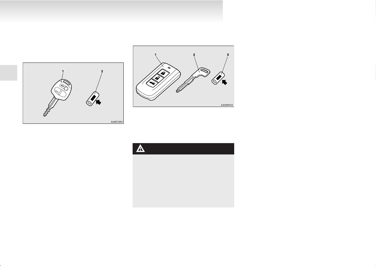
Type 1
The key fits all locks.
1
1- Keyless entry key `
2-
Keys
(with electronic immobilizer)
Key number tag
E00300102360
Type 2
The emergency key fits all locks.
1- Keyless operation key
electronic immobilizer and keyless en-
(with
try system function)
2- Emergency key
3- Key number tag
WARNING
carrying a key on flights, do not
When
l
press any switches on the key while on
the plane. If a switch is pressed on the
plane, the key emits electromagnetic
waves, which could adversely affect the
plane’s flight operation.
When carrying a key in a bag, be careful
that no switches on the key can be easily
pressed by mistake.
NOTE
The
key number is stamped on the tag as in-
l
dicated in the illustration.
Make a record of the key number and store
the key and key number tag in separate places, so that you can order a key in the event
the original keys are lost.
The key is a precision electronic device with
l
a built-in signal transmitter. Please observe
the following in order to prevent a malfunction.
• Do not leave anywhere that is exposed to
direct sunlight, for example on the dashboard.
• Do not dissemble or modify.
• Do not excessively bend the key or subject it to a strong impact.
• Do not expose to water.
• Keep away from magnetic key rings.
• Keep away from audio systems, personal
computers, TVs, and any other equipment that generates a magnetic field.
• Keep away from devices that emit strong
electromagnetic waves, such as cellular
phones, wireless devices and high frequency equipment (including medical devices).
• Do not wash with ultrasonic cleaners or
similar equipment.
• Do not leave the key where it may be exposed to high temperature or high humidity.
The engine is designed so that it will not
l
start if the ID code registered in the immobilizer computer and the key’s ID code do not
match. Refer to the section entitled “Electronic immobilizer” for details and key usage.
Pay attention to the following if the security
l
alarm is set to “Active”.
1-02
Refer to “Security alarm system” on page
OGEE12E1
1-29.
• If the security alarm system is in the system armed mode, the alarm will sound if
the doors are opened after being unlocked
with the key, the inside lock knob or the
central door lock switch (vehicles equipped with the central door lock switch).
• Even if the security alarm is set to “Active”, the system preparation mode is not
entered if the keyless entry system or the
keyless operation function was not used
to lock the vehicle.
Electronic immobilizer (Anti-
theft starting system)
vehicles equipped with the keyless operation
[For
system]
For information on operations for vehicles equipped with the keyless operation system, refer to
“Keyless operation system: Electronic immobilizer
(Anti-theft starting system)” on pages 1-11, 1-15.
[Except for vehicles equipped with the keyless operation system]
The electronic immobilizer is designed to reduce
significantly the possibility of vehicle theft. The purpose of the system is to immobilize the vehicle if
an invalid start is attempted. A valid start attempt
can only be achieved, using a key “registered” to
the immobilizer system.
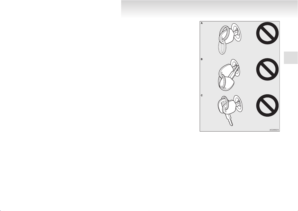
NOTE
In the following cases, the vehicle may not
l
be able to receive the registered ID code
from the registered key and the engine may
not start.
• When the key contacts a key ring or other
metallic or magnetic object (Type A)
• When the key grip contacts metal of another key (Type B)
• When the key contacts or is close to other
immobilizing keys (including keys of other vehicles) (Type C)
In cases like these, remove the object or
additional key from the vehicle key. Then
try again to start the engine. If the engine
does not start, we recommend you to contact your MITSUBISHI MOTORS Authorized Service Point.
E00300201898
Locking and unlocking
NOTE
If
you lose your key, contact your
l
MITSUBISHI MOTORS Authorized Service
Point as soon as possible.
To obtain a replacement or extra spare key,
take your vehicle and all remaining keys to
your MITSUBISHI MOTORS Authorized
Service Point. All the keys have to be re-registered in the immobilizer computer unit.
The immobilizer can register up to 8 different keys.
1
1-03
Locking and unlocking
OGEE12E1
1
CAUTION
Don’t make any alterations or additions
l
to the immobilizer system; alterations or
additions could cause failure of the immobilizer.
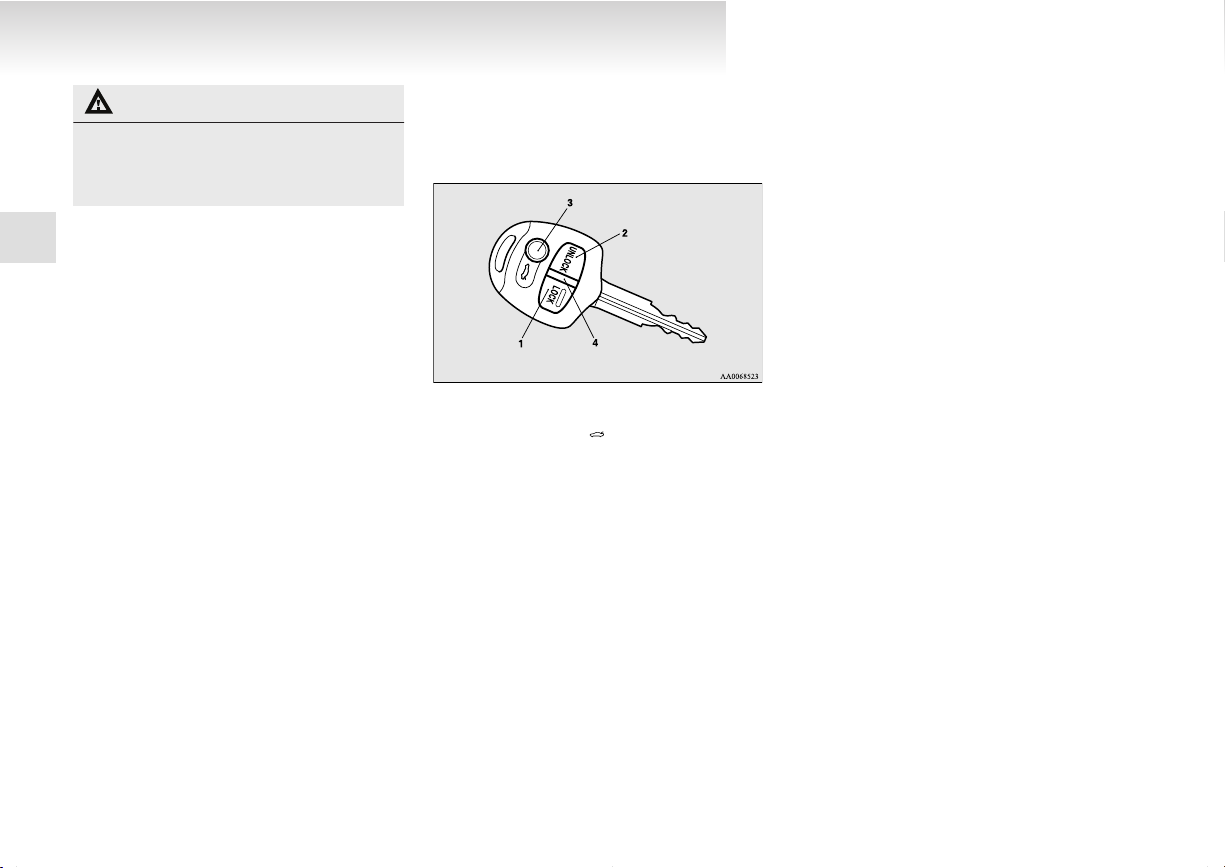
Keyless entry system*
Press
the remote control switch to lock or unlock
the doors and to open the trunk lid.
1- LOCK switch
UNLOCK switch
23-
Electric trunk lid (
Indication lamp
4-
) switch
E00300302405
To lock
Press the LOCK switch (1). All the doors will be
locked. The turn-signal lamps will blink once.
To unlock
Press the UNLOCK switch (2). All the doors will
be unlocked. If the front room lamp switch is in the
“DOOR” position or the rear room lamp switch (except in a vehicle with a sunroof) is in the middle (•)
position, the room lamp will come on for approximately 15 seconds and the turn-signal lamps will
blink twice.
The position and tail lamps will also turn on for
about 30 seconds.
Refer to “Welcome light” on page 3-40.
NOTE
On
vehicles equipped with the central door
l
lock switch, the door unlock function can be
set so that only the driver’s door unlocks
when the UNLOCK switch (2) is pressed once.
If the door unlock function is set to work as
described above, all the doors unlock when
the UNLOCK switch is pressed two times in
succession.
Refer to “Setting of door unlock function”
on page 1-05.
To open the trunk lid
Press the electric trunk lid switch (3) twice within
about 5 seconds and the trunk lid will be opened.
The trunk lid must be closed manually after it has
been opened.
NOTE
The indication lamp (4) comes on each time
l
a switch is pressed.
If the UNLOCK switch (2) is pressed and no
l
door is opened within approximately 30 seconds, relocking will automatically occur.
It is possible to modify functions as follows:
l
For further information, please contact your
MITSUBISHI MOTORS Authorized Service
Point.
On vehicles equipped with MITSUBISHI
Multi-Communication System (MMCS),
screen operations can be used to make the adjustment. Refer to the separate owner’s manual for details.
• The time for automatic relocking can be
changed.
1-04
• Activating the operation confirmation
OGEE12E1
function (blinking of the turn-signal
lamps) only during locking, or only during unlocking.
• The confirmation function (this indicates
locking or unlocking of the doors with
the blink of the turn-signal lamps) can be
deactivated.
• The number of times the turn-signal
lamps are blinked by the confirmation
function can be changed.
The keyless entry system does not operate in
l
the following conditions:
• The key is left in the ignition switch.
• The door is open.
The remote control switch will operate with-
l
in about 4 m from the vehicle. However, the
operating range of the remote control switch
may change if the vehicle is located near a
power station, or radio/TV broadcasting station.
If either of the following problems occurs,
l
the battery may be exhausted.
• The remote control switch is operated at
the correct distance from the vehicle, but
the doors are not locked/unlocked in response.
• The trunk lid cannot be opened.
• The indication lamp (4) is dim or does
not come on.
For further information, please consult
your MITSUBISHI MOTORS Authorized Service Point.
If you replace the battery yourself, refer
to “Procedure for replacing the remote
control switch battery” on page 1-05 .
your remote control switch is lost or dam-
If
l
aged, please contact your MITSUBISHI
MOTORS Authorized Service Point for a replacement remote control switch.
If you wish to add a remote control switch,
l
please contact your MITSUBISHI MOTORS
Authorized Service Point. A maximum of 8
remote control switches are available for
your vehicle.
Setting of door unlock function (vehicles equipped with the central door
lock switch)
The door unlock function can be set to the following two conditions.
Each
time the door unlock function is set, a chime
will sound to tell you the condition of the door unlock function.
Number of
chimes
One chime All doors unlock
Two chimes Driver’s door unlock only
1. Remove the key from the ignition switch.
the combination headlamps and dipper
2. Place
switch in the “OFF” position, and leave the
driver’s door open.
3. Press the LOCK switch (1) for 4 to 10 sec-
onds and press the UNLOCK switch (2) during this time.
4. Release in sequence the LOCK and UN-
LOCK switches within 10 seconds of pressing the LOCK switch in step 3.
Condition
E00310300198
Locking and unlocking
NOTE
On
vehicles equipped with MITSUBISHI
l
Multi-Communication System (MMCS),
screen operations can be used to make the adjustment. Refer to the separate owner’s manual for details.
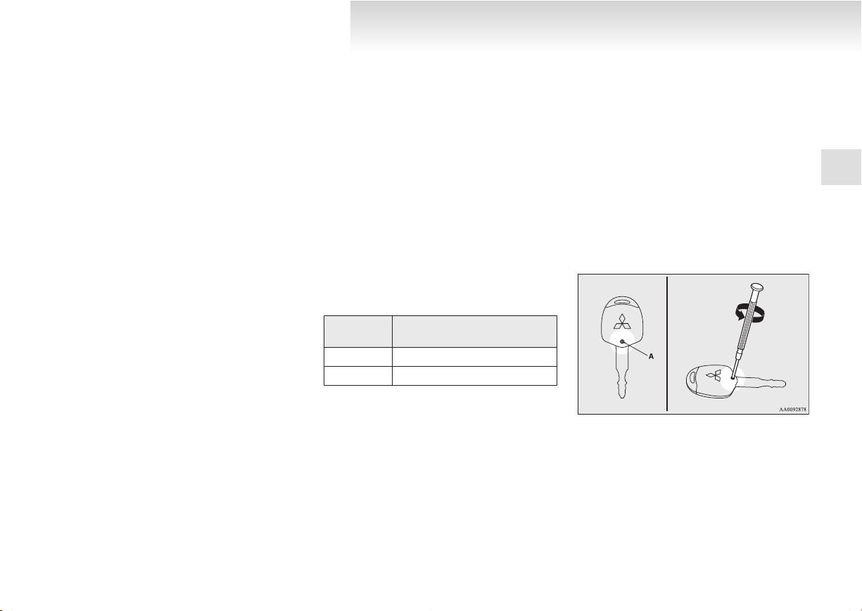
Procedure for replacing the remote control switch battery
1. Before
2. Remove the screw (A) from the remote con-
3. With
replacing the battery, remove static
electricity from your body by touching a metal grounded object.
trol switch.
the MITSUBISHI mark facing you, insert the clothcovered tip of a straight blade
(or minus) screwdriver into the notch in the
E00309500174
1
1-05
Coin type battery
CR1616
- side
+ side
Locking and unlocking
OGEE12E1
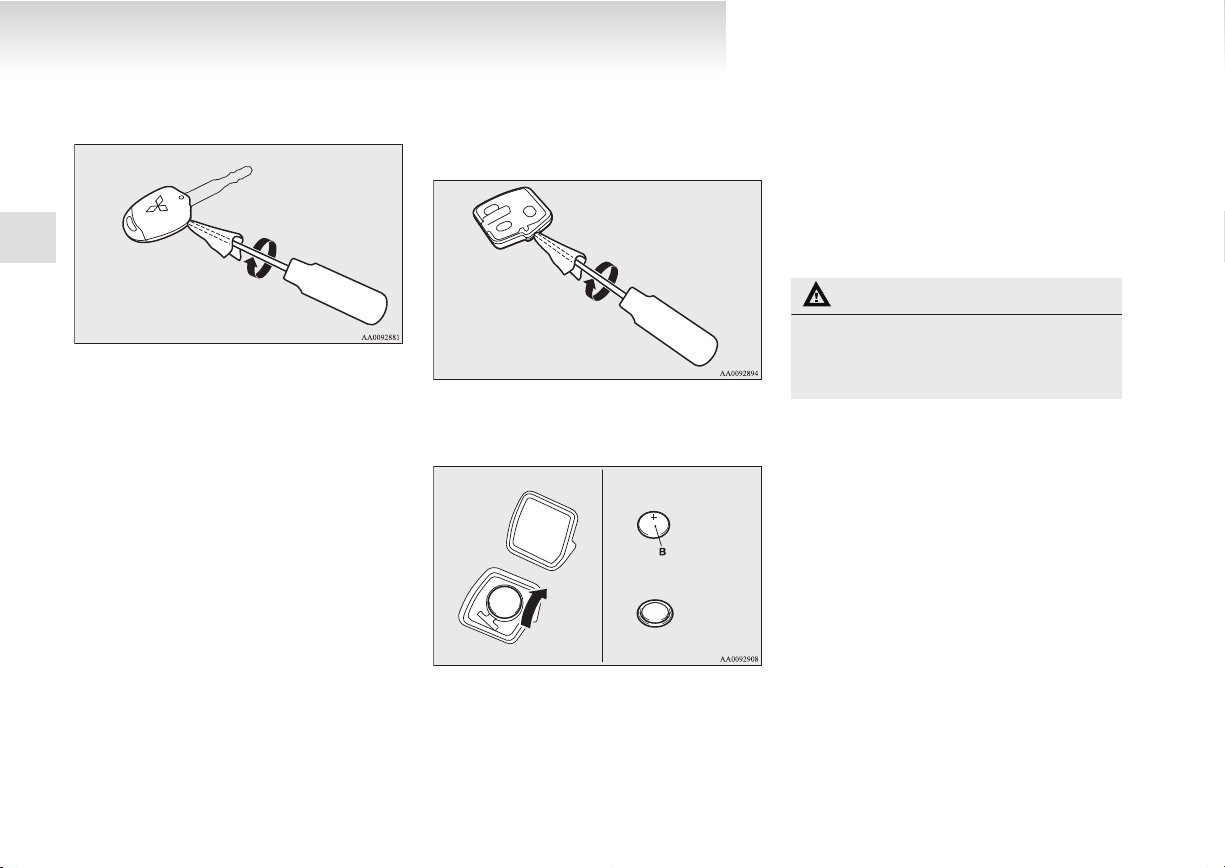
remote control switch case and use it to open
the case.
1
NOTE
Be
l
MITSUBISHI mark facing you. If the
MITSUBISHI mark is not facing you when
you open the remote control switch case, the
switches may come out.
sure to perform the procedure with the
4. Remove
the remote control switch case. Then, open
the remote control transmitter using the method described in step 3.
5. Remove the old battery.
6. Install
the remote control transmitter from
a new battery with the + side (B) down.
10. Check
the keyless entry system to see that it
works.
NOTE
You may purchase a replacement battery at
l
an electric appliance store.
A MITSUBISHI MOTORS Authorized Serv-
l
ice Point can replace the battery for you if
you prefer.
CAUTION
When
l
the remote control switch case is
opened, be careful to keep water, dust,
etc. out. Also, do not touch the internal
components.
1-06
7. Close the remote control transmitter firmly.
8.
Place the remote control transmitter in the remote control switch case, then securely close
the remote control switch case.
9. Attach the screw (A) removed in step 2.
 Loading...