

New Vehicle Manual
New Vehicle Manual
CONTENTS
LANCER
EVOLUTION VIII
MR
FOREWORD
This manual contains details of the main changes to
the 2004 model Lancer Evolution VIII MR. Only
differences to the current Lancer Evolution VIII are
included, so please use this manual in conjunction with
the related information specified on the next page.
This information relates to the current vehicle (February
2004). Since specifications will change, some of the
information contained here will inevitably be
superseded.
Note that SI units are used in this manual. Old units are
not shown alongside them.
(However, old units are used for some figures we have
taken from existing documents).
General..........................................
Engine ...........................................
Power Train...................................
Drive Control ................................
Body ..............................................
Exterior..........................................
Interior...........................................
0
1
2
3
4
5
6
Any opinions, requests, or questions concerning
this manual, should be written on the ‘Servicing
Comments Form’ at the end, and sent to us by
fax.
February 2004
MITSUBISHI MOT
OR CORPORATION
Equipment.....................................
Reference Materials .....................
There are no changes to the shaded chapter,
so it is not included at all in this manual.
7
8
This manual is printed on recycled paper
.

Title
No.
Issue
Date
Title
No.
Issue Date
Body Manuals (Service
Manual)
• Mirage, Lancer
(supplement)
• Lancer Cedia
• Lancer Cedia
(supplement)
• Lancer Evolution VII
(supplement)
• Lancer Cedia
(supplement)
• Lancer Evolution VIII MR
(supplement)
1036F52
1036K50
1036K51
1036K52
1036K53
1036K54
Aug 1996
May 2000
July 2000
May 2001
Oct 2001
Feb 2004
Electrical Wiring Diagrams
Service Manual
• Lancer Evolution VIII
• Lancer Evolution VIII MR
(supplement)
1036K77
1036K80
Jan 2003
Feb 2004
New Vehicle Manuals
• Mirage, Lancer
• Mirage, Lancer
• Mirage, Lancer
• Mirage, Lancer
• Lancer
• Mirage, Lancer
• Lancer
• Lancer
• Lancer Cedia
• Lancer Cedia
• Lancer Evolution VII
• Lancer Cedia
• Lancer Cedia
• Lancer Evolution VII
• Lancer Cedia
• Lancer Evolution VIII
• Lancer
• Lancer
1036F30
1036F31
1036F32
1036F33
1036F34
1036F35
1036F36
1036F37
1036K30
1036K31
1036K32
1036K33
1036K34
1036K35
1036K36
1036K37
1036K38
1036K39
Oct 1995
Jan 1996
Aug 1996
Jul 1997
Jan 1998
Oct 1998
Jan 1999
Dec 1999
May 2000
July 2000
Jan 2001
May 2001
May 2001
Jan 2002
May 2002
Jan 2003
Feb 2003
Dec 2003
Engine Service Manual
• 4G6 Engine
• 4G6 Engine
(supplement)
1039G46
1039G63
Jan 2001
Jan 2003
Service Manuals
• Lancer Cedia
• Lancer Cedia
(supplement)
• Lancer Evolution VII
(supplement)
• Lancer Cedia
(supplement)
• Lancer Cedia
(supplement)
• Lancer Evolution VII
(supplement)
• Lancer Cedia
(supplement)
• Lancer Evolution VIII
(supplement)
• Lancer (supplement)
• Lancer (supplement)
• Lancer Evolution VIII
MR (supplement)
1036K00
1036K01
1036K02
1036K03
1036K04
1036K05
1036K06
1036K07
1036K08
1036K09
1036K10
May 2000
July 2000
Jan 2001
May 2001
Oct 2001
Jan 2002
May 2002
Jan 2003
Feb 2003
Dec 2003
Feb 2004
Transmission Service
Manual
• W5M51 Manual
Transmission
• W5M51 Manual
Transmission
(supplement)
• W6MAA Manual
Transmission
1039M17
1039M22
1039M23
Jan 2001
Jan 2003
Jan 2003
Related information
GENERAL – TECHNICAL FEATURES
SECTION 0
GENERAL
CONTENTS
00-1
Vehicle Identification..............................0-1
Implementation Code .............................0-1
Development Aims .................................0-1
Overview of Lancer Evolution VIII MR. 0-2
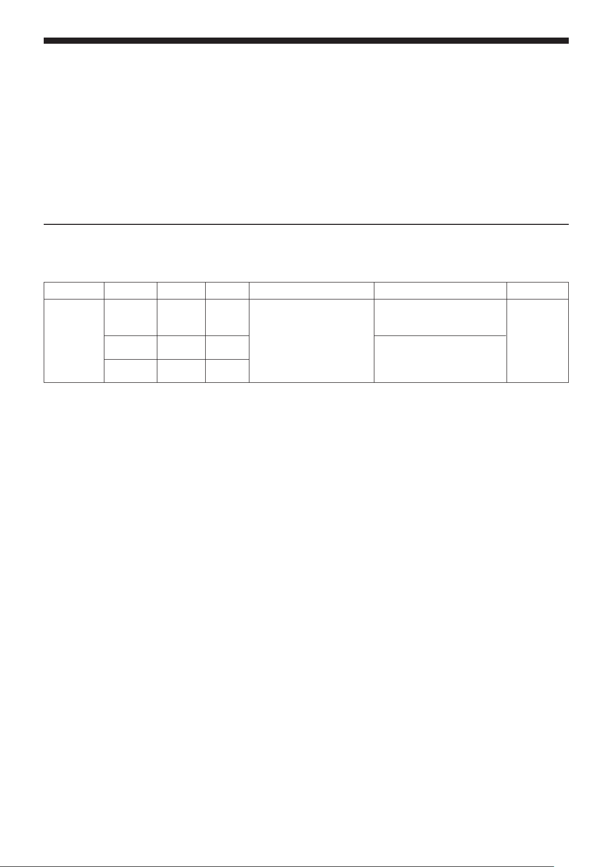
Model line-up
Model Version ’04 Model Grade Engine Model Transmission Fuel System
GH-CT9A SNDFZ
SJDFZ
SJGFZ
Note
¡ = Continued model
¡
¡
¡
RS
RS
GSR
4G63
(2 000 DOHC 16 valve
intercooler turbo)
W5M51 (4WD, 5M/T)
W6MAA (4WD, 6 M/T)
MPI
Applied vehicles
GH-CT9A: CT9A-0300001 ~
Development Aims
The launch of the Lancer Evolution VIII MR is the result of our pursuit of further advances and improvements based on the
Lancer Evolution VIII, with the aim of maintaining and strengthening the Mitsubishi Evolution brand.
0-2
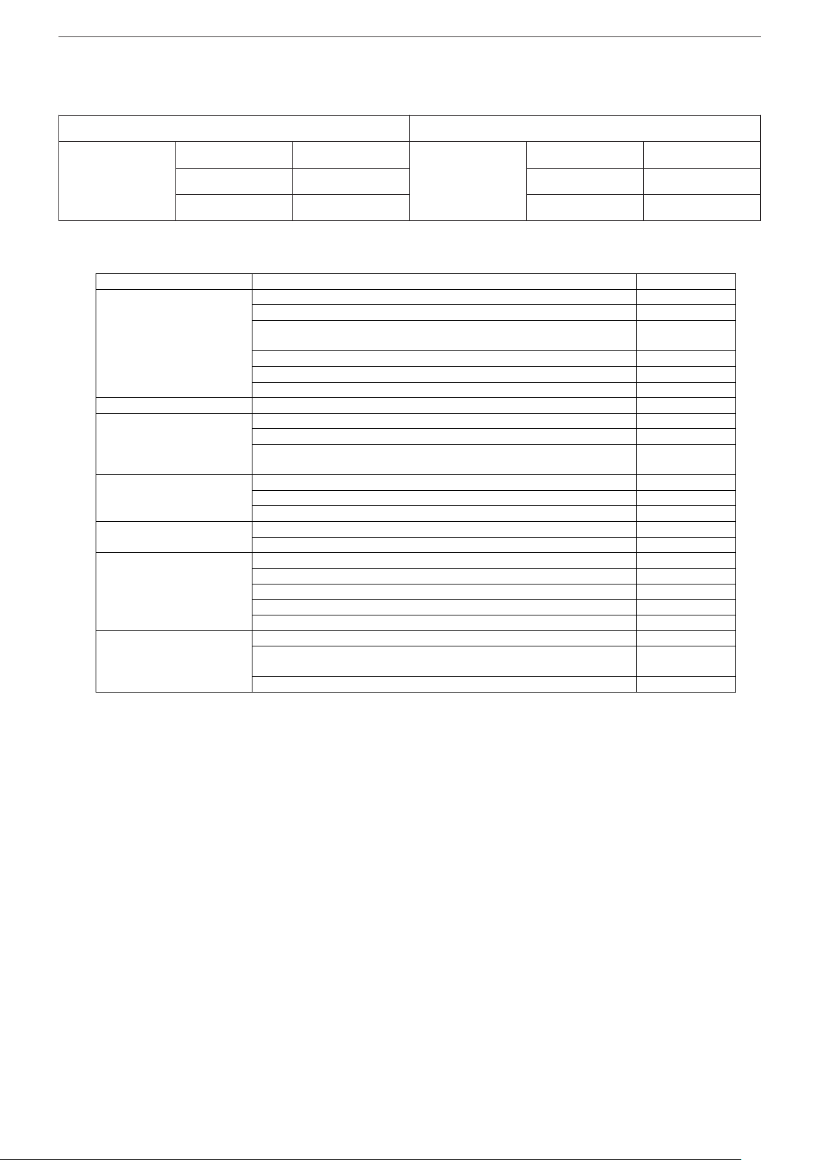
Section
Difference from Lancer Evolution VIII
Page
Change to cam profile (6 M/T)
1-5
Enlarged turbo nozzle diameter (6 M/T)
1-6
Adoption of tail pipe with built-in sound proofing in exhaust main
silencer (6 M/T)
1-7
Addition of wastegate solenoid valve (1 ‡ 2)
*1
1-8
Change to catalyst volume (2.0 l. ‡ 1.5 l.) (6 M/T)
-
Engine
Enlarged engine oil cooler
Power train
Change to super AYC differential
2-1
Installation of Bilstein shock absorbers
*2
3-1
Optional BBS 17-inch alloy wheels (new design)
3-1
Drive control
Black finish on spokes of Momo genuine leather steering wheel
(Type A) (GSR)
-
Aluminium used in roof panel and side door beams
4-1
Change to body colour
4-1
Body
Boot lid opener fitted as standard (RS)
Addition of Evolution MR logo
5-1
Exterior
Outer panel on rear spoiler and “Lancer” logo changed to dark grey
Ornamentation added to carbon finish instrument panel
Centre panel changed to black
Shift lever with special Lancer Evolution MR logo plate (6 M/T)
Door trim fabric changed
-
Interior
Recaro seat fabric changed to suede finish all-round (GSR)
Change to combination meter
7-1
Black outs on extensions of headlights (discharge) and rear
combination lamps
-
Equipment
Adoption of roof aerial (RS)
-
GENERAL – OVERVIEW OF THE LANCER EVOLUTION VIII MR
Overview of the Lancer Evolution VIII MR
Lancer Evolution VIII MR Lancer Evolution VIII
GH-CT9A SNDFZ RS (5M/T) GH-CT9A SNDFZ RS (5M/T)
SJDFZ RS (6M/T) SJDFZ RS (6M/T)
SJGFZ GSR SJGFZ GSR
Differences from the Lancer Evolution VIII
Notes:
*1
: The No.2 wastegate solenoid valve does not operate in vehicles with 5 M/T transmission.
*2
: Joint development of special shock absorbers for the Lancer Evolution VIII MR, with the German firm, Bilstein.
ENGINE (4G6) – GENERAL
SECTION 1
ENGINE (4G6)
CONTENTS
1-1
General ....................................................1-1
1. Major Specifications....................................1-1
2. Engine Performance Curve.........................1-2
Base Engine (6 M/T) ...............................1-2
1. Cylinder head gasket...................................1-2
2. Pistons..........................................................1-3
3. Piston rings (2nd) ........................................1-3
4. Oil rings ........................................................1-4
5. Counterbalance shaft .................................1-4
6. Camshaft.......................................................1-5
Intake / Exhaust System (6 M/T)............1-6
1. Exhaust system ...........................................1-6
Control system (6 M/T)...........................1-8
1. Supercharging pressure control..............1-10
General
The 4G63-T/C engine fitted in the Lancer Evolution VIII MR is basically the same as the 4G63-T/C engine used in the Lancer
Evolution VIII.
The basic structure is the same in both the 6M/T (6-speed) and 5M/T (5-speed) versions, but the following improvements have
been made to the 6M/T version, in order to achieve higher performance.
• Adoption of 5-ply cylinder head gasket
• Addition of V-shaped groove in piston , and modified shape in cooling channel
• Reduced oil consumption by increasing tension in piston rings and reducing end-to-end gap
• Extra durability and reduced oil consumption by using new treatment on outer surface of oil ring side rail, and altering
thickness
• Lighter counterbalance shaft
• Increased output at high engine speeds by modifying intake cams
Major Specifications
Item 6 M/T 5M/T
Total Displacement cc 1997
Combustion chamber Pentroof type
Bore x stroke (mm) 85.0 x 88.0
Compression ratio 8.8
Camshaft arrangement DOHC-4 valve
Fuel Premium unleaded
Max. output (kW/rpm) 206/6500
Max. torque (Nm/rpm) 400/3500 392/3500
Fuel system Electronic controlled multipoint fuel injection
Ignition system Electronic controlled two-coil
Lash adjuster Equipped
1-2
ENGINE (4G6) – GENERAL, BASE ENGINE (6 M/T)
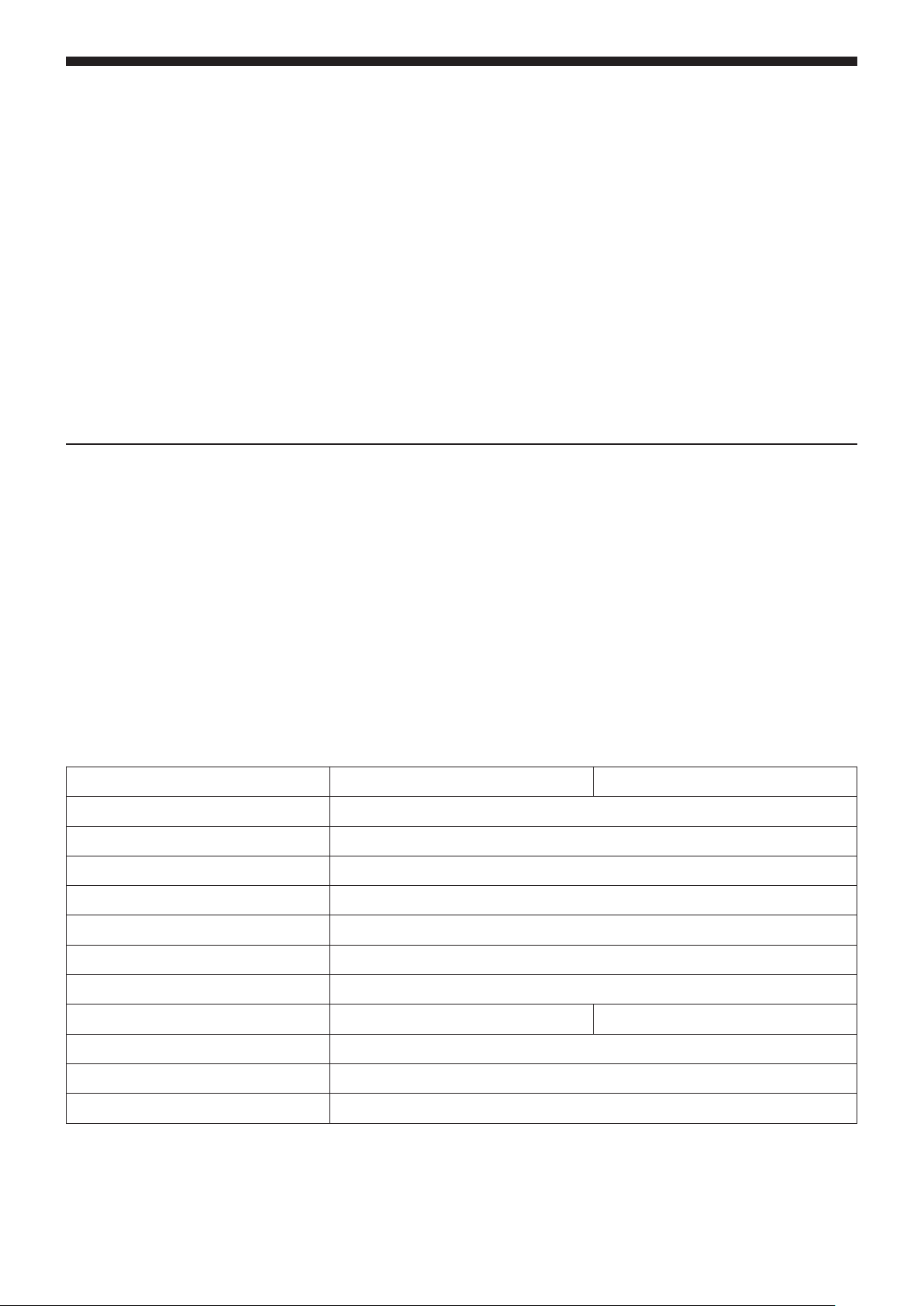
2. Engine performance curve (6 M/T)
Shaft output (kW)
Base Engine (6 M/T)
Shaft torque (N•m)
Engine r.p.m.
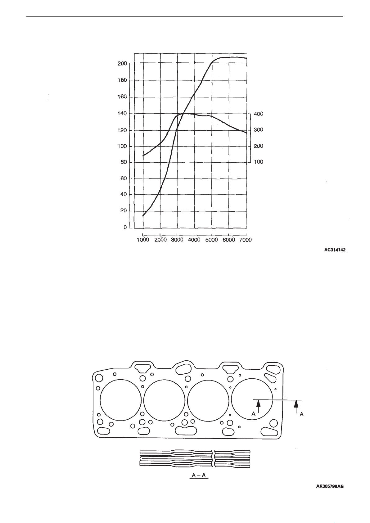
1. Cylinder head gasket
5-ply metal gasket has been introduced, in order to improve sealing properties.
A
ENGINE (4G6) – BASE ENGINE (6 M/T)
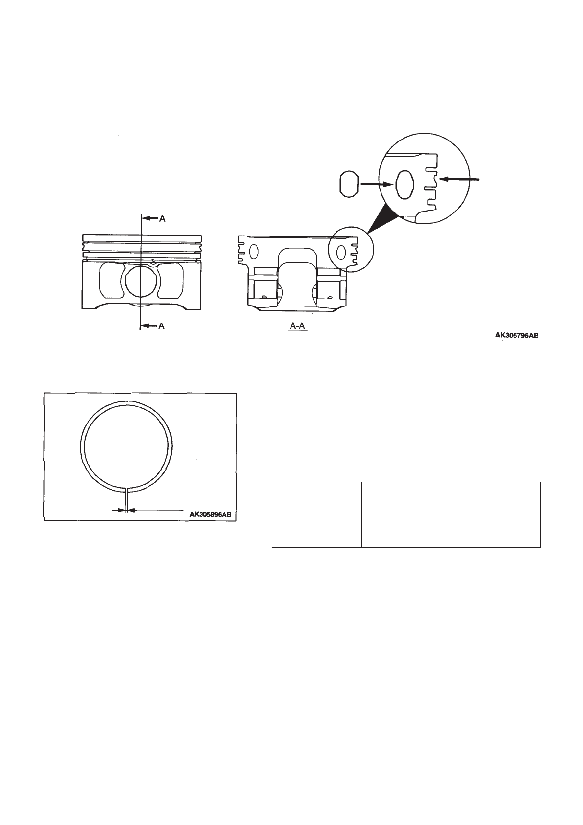
2. Pistons
• Addition of V-shaped groove.
A V-shaped groove has been formed in the second land, with a view to reducing oil consumption.
Modification of cooling channel.
•
The shape of the cooling channel, which recycles the oil, has been modified in order to improve recycling efficiency.
1-3
Modified shape of
cooling channel
V-shaped
groove added
3. Piston Rings (2nd)
To increase the tension in the piston rings, they have been changed
to ductile cast iron, from the standard cast iron used previously.
The end to end gap in the rings was also reduced.
These modifications are designed to reduce oil consumption.
End to end gap
Item Evolution VIII MR Evolution VIII
Tension 10.5 N 7.0 N
End to end gap 0.30 – 0.45 mm 0.35 – 0.50 mm
1-4
ENGINE (4G6) – BASE ENGINE (6 M/T)
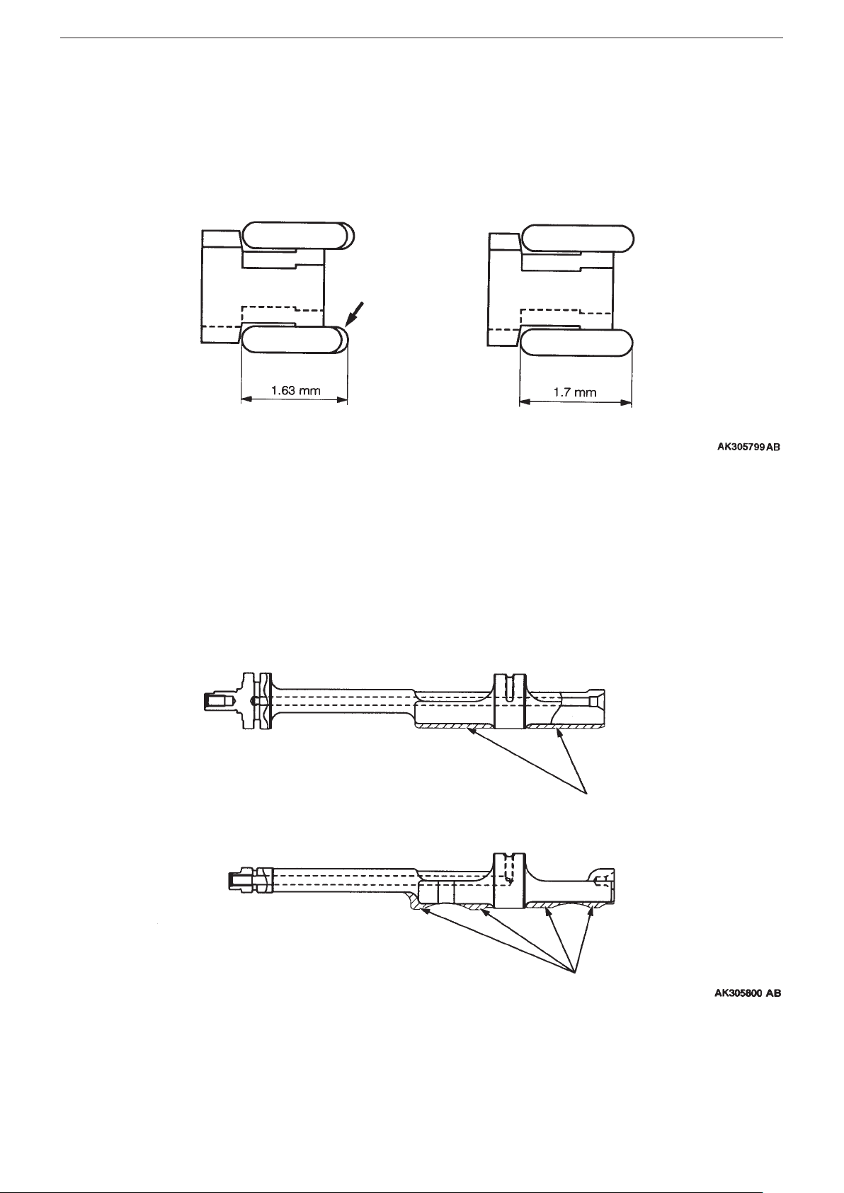
4. Oil Rings
The outer circumference of the side rail has been treated with chrome nitride. The thickness of the side rail has also been
reduced from 1.7 mm to 1.63 mm, with a view to increasing durability and reducing oil consumption.
(Evolution VII MR) (Evolution VIII)
Chrome nitride
5. Counterbalance shaft
The shape of the shaft was changed in order to reduce weight.
Counterbalance shaft (right)
Counterbalance shaft (left)
Thickness
reduced
Thickness
reduced

ENGINE (4G6) – BASE ENGINE (6 M/T)
1-5
6. Camshaft
Output at high engine speeds has been improved by altering the cam profile of the intake camshaft, and optimizing the valve
timing.
Evolution VIII MR Evolution VIII
Cam height mm 35.96 35.79
Evolution VIII MR Evolution VIII
T.D.C (top dead centre) T.D.C (top dead centre)
Intake valve open
Intake valve
closed
B.D.C (Bottom dead centre) B.D.C (Bottom dead centre)
Exhaust
valve closed
Exhaust
valve open
Intake valve open
Intake valve
closed
Exhaust
valve closed
Exhaust
valve open

1-6
ENGINE (4G6) – INTAKE / EXHAUST SYSTEM (6 M/T)
Intake / Exhaust System (6 M/T)
1. Exhaust system
1-1 Turbocharger
A large-nozzle 10.5T turbo has been adopted in order to improve mid to high-range torque. Optimum control of the
supercharging pressure has ensured good torque and response at medium engine speeds.
The positions of the turbine housing and the wastegate holes have also been changed to achieve smoother outflow and
increase low-speed torque. Along with these modifications, the wastegate valve has been changed from an oval to a circular
valve.
(Evolution VIII MR) (Evolution VIII)
Turbine housing
Wastegate holes
Turbine housing
Wastegate holes
Circular valve
Oval valve
ENGINE (4G6) – INT
AKE / EXHAUST SYSTEM (6 M/T)
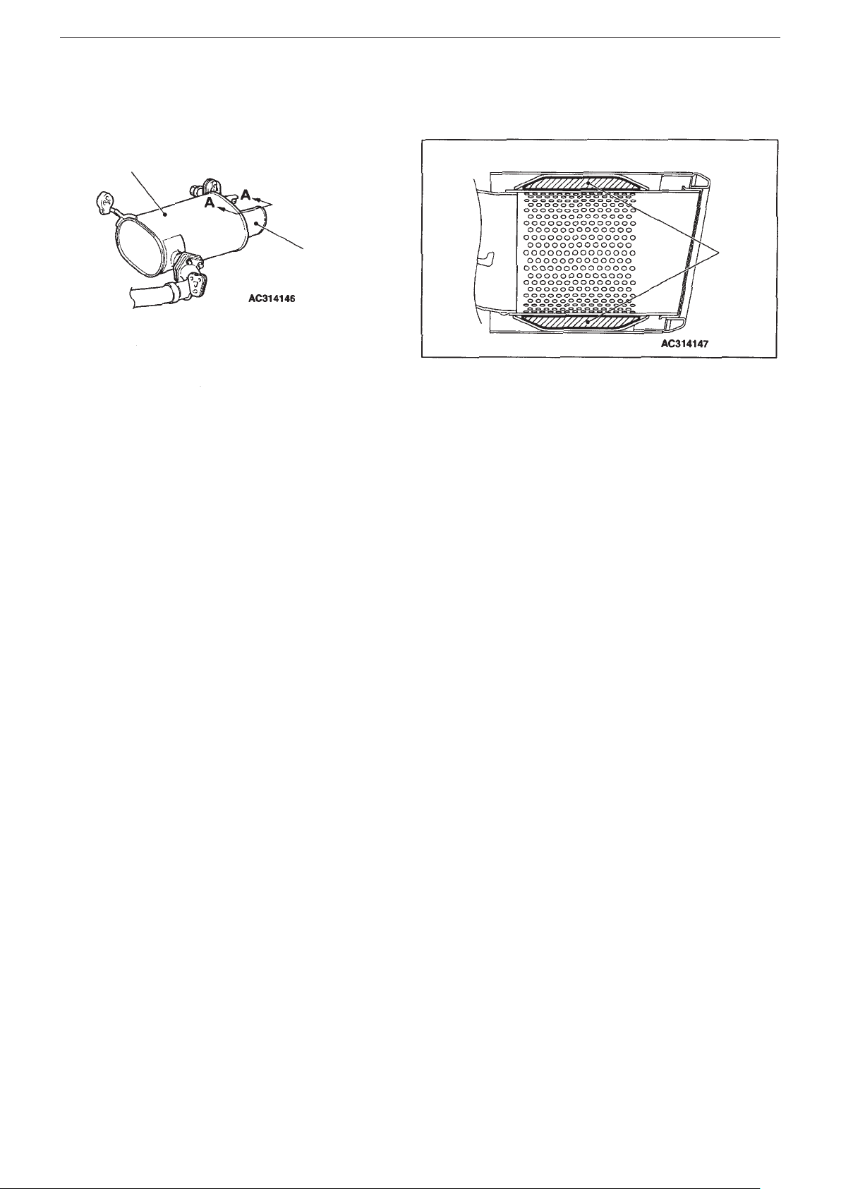
1-2 Exhaust silencer
A tailpipe with built-in sound-absorbing material has been adopted, in order to increase the silencing effect.
Structural diagram
1-7
Main exhaust
silencer
Tailpipe
(with built-in soundabsorbing material)
Cross-section
A–A
Soundabsorbing
material
1-8
ENGINE (4G6) – GENERAL, BASE ENGINE (6 M/T)
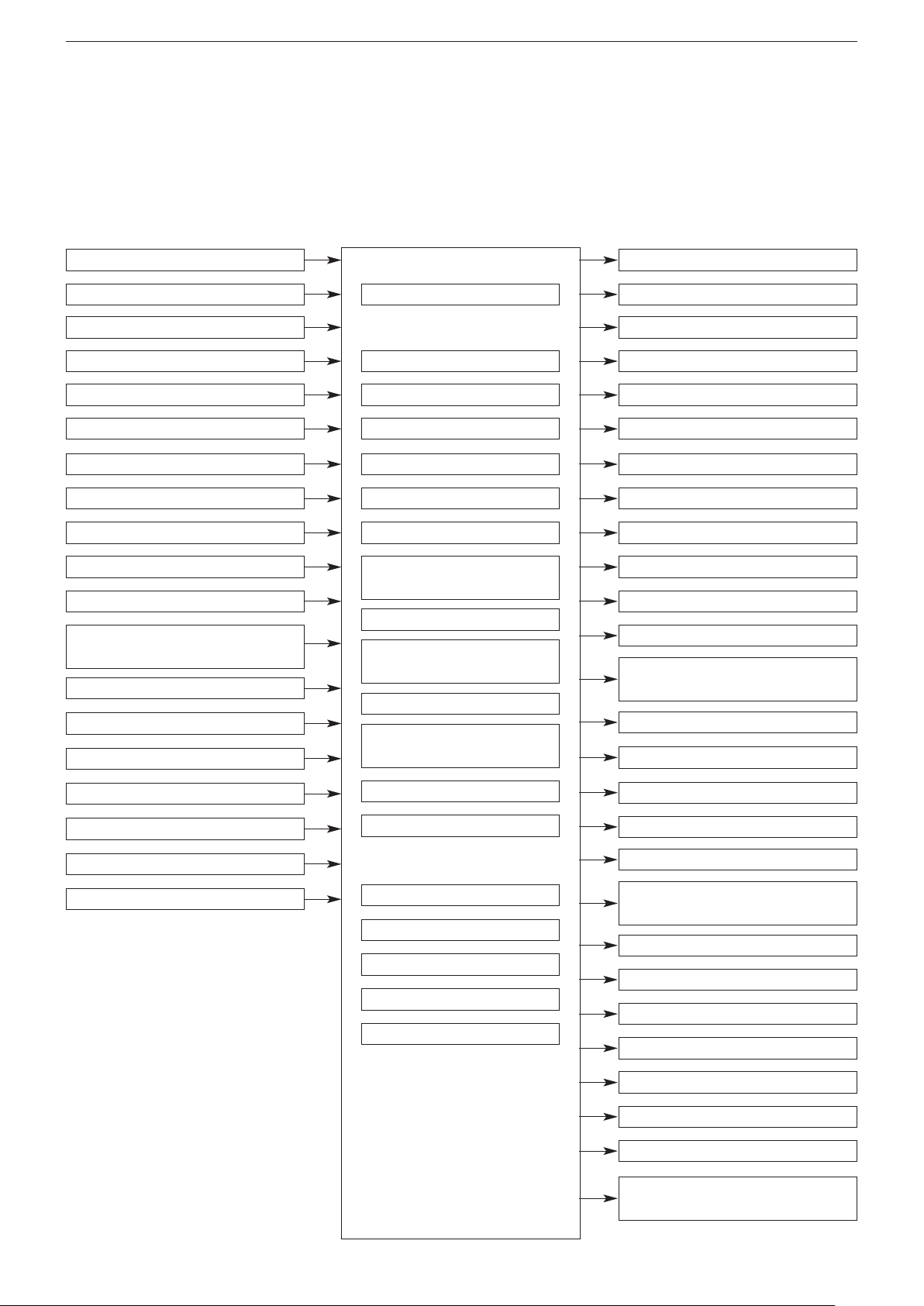
Control system (6M/T)
The following changes have been made, based on the control system in the 4G63-DOHC-T/C engine fitted in the current
Lancer Evolution VIII.
* Addition of wastegate solenoid valve (1 valve –> 2 valves)
System Block Diagram
Air flow sensor (AFS)
Air temperature sensor
Atmospheric pressure sensor
Water temperature sensor
Throttle position sensor (TPS)
A/C switch
A/C load signal
Cam position sensor
Crank angle sensor
Alternator FR terminal
Vehicle speed sensor
Power steering fluid pressure
switch
Knock sensor
Intercooler water spray (auto)
Intercooler water spray (manual)
Engine ECU
Fuel injection control
Idle speed control (ISC)
Ignition timing control
Engine control relay control
Fuel pump relay control
A/C relay control
Fan motor control (radiator)
Fan relay control (A/C
condenser)
Alternator control
Air flow sensor filter reset
control
Fuel pressure control
Supercharging pressure
control
No. 1 indicator
No. 2 indicator
No. 3 indicator
No. 4 indicator
ISC servo (stepper motor)
Ignition coil A (No.1 – No.4)
Ignition coil B (No.2 – No.3)
Engine control relay
Fuel pump relay 2
Fuel pump relay 3
A/C relay
Fan controller (radiator fan)
Fan motor relay (HI, LOW)
(A/C condenser)
Alternator G terminal
Air flow sensor
O
sensor
2
Ignition switch –IG
Ignition switch –ST
Power supply
Secondary air control
Intercooler water spay control
Engine warning light control
O
sensor heater control
2
Purge control
Diagnosis output
RAM data transmission
Fuel pressure control valve
No. 1 wastegate solenoid valve
No. 2 wastegate solenoid valve
Secondary air control solenoid
valve
Intercooler water spray relay
Intercooler water spray lamp
achometer
T
Engine warning lights
O
sensor heater
2
Purge control solenoid valve
Diagnosis output terminal
Diagnosis output terminal (for
-II)
MUT
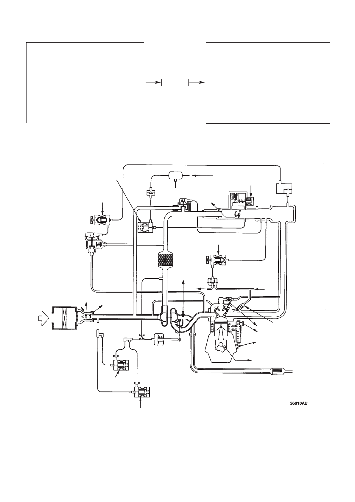
Control system diagram
ENGINE (4G6) – GENERAL, BASE ENGINE (6 M/T)
1-9
★1. O2 sensor
Air flow sensor
★2.
Air intake sensor
★3.
Throttle position
★4.
sensor
★5. Cam position sensor
★6. Crack angle sensor
Atmospheric pressure
★7.
sensor
ater temperature
★8. W
sensor
★9. Knock sensor
Power supply
•
Ignition switch IG
•
Ignition switch ST
•
Vehicle speed sensor
•
• A/C switch
A/C load signal
•
Power steering fluid
•
pressure switch
Alternator FR signal
•
Intercooler water spray
•
switch (auto)
Intercooler water spray
•
switch (manual)
✩6. Purge control
solenoid valve
✩7. Secondary air
control solenoid valve
Check
valve
Engine ECU
Canister
By-pass
valve
✩1. Injector
✩2. ISC servo (stepper
motor)
✩3. Fuel pressure control
solenoid valve
✩4. No.1 wastegate solenoid
valve
✩5. No.2 wastegate solenoid
valve
✩6. Purge control solenoid
valve
✩7. Secondary air control
solenoid valve
From fuel tank
✩2. ISC servo
Throttle
★4.
position
sensor
Engine control relay
•
Fuel pump relay 2, 3
•
A/C relay
•
Ignition coil
•
• Fan controller
Condenser fan relay (HI)
•
Condenser fan relay
•
(LOW)
Engine warning lamp
•
Diagnosis output
•
Alternator G terminal
•
Intercooler water spray
•
relay
Intercooler water spray
•
lamp
Vacuum
tank
Air
intake
Secondary
air valve
★2. Air flow sensor
Atmospheric pressure
★7.
sensor
★3.
sensor
✩4. No.1
wastegate
solenoid valve
Air intake
astegate actuator
W
★1. O
control solenoid valve
sensor
2
To fuel
tank
✩3. Fuel pressure
Fuel pressure
regulator
From fuel
pump
✩1. Injector
Cam position sensor
★5.
★8.Water temperature sensor
★9.Knock sensor
Crack angle sensor
Catalytic converter
✩5. No.2 wastegate
solenoid valve
Only operates on 6M/T

1-10
ENGINE (4G6) – CONTROL SYSTEM (6 M/T)
1. Supercharging pressure control
The maximum torque has been increased, compared to the 4G63-DOHC-T/C engine in the current Lancer Evolution VIII, by
installing an additional wastegate solenoid valve (increased from 1 to 2 valves).
Air flow
sensor
Crank angle
sensor
Knock
sensor
Battery
Secondary air
control solenoid
valve
Secondary
air valve
Ignition
switch
Air
intake
No. 1
wastegate
solenoid
valve
No. 2 wastegate
solenoid valve
Vacuum tank
Bypass valve
Intercooler
Turbocharger
Wastegate
actuator
Engine
ECU
By adding a parallel No.2 wastegate solenoid valve to the previous system, provides extra relief capacity for the pressure
applied to the wastegate actuator thus increasing the range of supercharging pressure..
The engine ECU raises the supercharging pressure even further, thus raising the maximum torque, by driving the No.2
wastegate solenoid valve when the engine approaches maximum torque.
The No.1 wastegate solenoid valve is essentially controlled in the same way as previously
.

Power Train – Differential
SECTION 2
POWER TRAIN
CONTENTS
Differential ..............................................2-1
Differential
2-1
The following changes have been made to the Super
• Reduced weight: The weight of the differential has been reduced by building the clutch case from aluminium, rather than
steel, and partially revising the thickness of the clutch discs.
• Improved strength and durability: Strength and durability have been raised by adopting special high-strength steel for the
hypoid gears (pinion gear and drive gear), instead of the cast steel used previously.
• Improved control when ABS is operating: Revisions to the communications with the ABS-ECU and the control procedure
during ABS operation, as well as active ACD/AYC control in high friction road surfaces, such as circuits, have led to
increased steerability and stability.
Structural Diagram
Hypoid gears
AYC differential.
Clutch case
Clutch discs

3-1
DRIVE CONTROL – Front suspension, Rear suspension, Wheels, Tyres
SECTION 3
DRIVE CONTROL
CONTENTS
Front suspension....................................3-1
Wheels and Tyres ...................................3-1
Rear suspension.....................................3-1
Front suspension
Road-holding has been improved by the adoption of Bilstein shock absorbers.
(GRS: Standard; RS: Optional)
Notes :
* Bilstein are one of the world’s leading manufacturers of shock absorbers, and their products are used in racing vehicles
worldwide.
Rear suspension
• Road-holding has been improved by the adoption of Bilstein shock absorbers.
(GRS: Standard; RS: Optional)
• The specifications of the coil springs have been changed. (GSR)
Specifications
Item Lancer Evolution VIII MR GSR Lancer Evolution VIII GSR
Wire diameter mm 12
verage diameter mm
A
Free length mm 277 287
88
←
←
Wheels and Tyres
BBS lightweight forged alloy wheels are provided as an option,
which reduces the unsprung weight. Fitting these BBS lightweight
wheels allows the Bilstein shock absorbers to display their full
range of performance.
Note:
See “Section 8 Main Equipment” for detailed specifications.

BODY – MAIN BODY
SECTION 4
BODY
CONTENTS
4-1
Main Body................................................4-1
Body Panels .....................................................4-1
Paintwork.................................................4-1
Body colour chart ............................................4-1
Main Body
Body Panels
Vehicle weight has been reduced by using aluminium for the roof panels and the side door beams, in addition to the bonnet
panel and front wing panels, as previously.
: Parts made from aluminium
Paintwork
Body colour chart
Colour name
(Former name)
Cool Silver Metallic CL A31 CMA10031 Aluminium M Kansai Paint
Medium Purplish Grey Mica ES A39 CMA10039 Aluminium +
Solid White (Scotia White) 2E W83 AC10983 –– S Kansai Paint
Solid Red (Palma Red) JW P85 AC11185 –– S Kansai Paint
Note :
• The maintenance code is only for the top coat. S = Solid; M = Metallic; 2P = 2-coat pearl
• The name of the paint manufacturer is the name of the manufacturer of the paint used at the time of production.
Colour
symbol
Colour
code
Colour (paint)
number
Coating ingredient Maintenance
symbol
2P Nippon Paint
interference mica
Name of paint
manufacturer

5-1
EXTERIOR – MARKINGS
SECTION 5
EXTERIOR
CONTENTS
Markings ..................................................5-3
Markings
An Evolution MR logo has been added.
Evolution MR logo

EQUIPMENT – COMBINATION METER
SECTION 7
EQUIPMENT
CONTENTS
Combination meter.................................7-1
Combination meter
7-1
The combination meter has been changed as illustrated below
(Lancer Evolution VIII MR) (Lancer Evolution VIII)
Marking changed
.

8-1
GH-CT9A
Item
SNDFZ
SJDFZ
SJGFZ
Classification No.È
079, 080, 085, 086,
091, 092, 097, 098
083, 084, 089,
090, 095, 096,
099~102
105, 106, 109,
110, 113, 114,
117, 118
119
Vehicle length mm
4490
Vehicle width mm
1770
Vehicle height mm
1450
Wheelbase mm
2625
Front
1500
1515
¨
¨
Dimensions
Track mm
Rear
1500
1515
¨
¨
Weight
See weight chart
Left
50˚
Performance
Max.
angle of
stability
Right
50˚
Wheel alignment
Front 2 drive – Rear 2 drive
Front
Other
Tyre
size
Rear
205/65R15 94H
235/45ZR17
¨
¨
REFERENCE MATERIAL – MAIN SPECIFICATIONS
SECTION 8
REFERENCE MATERIAL
CONTENTS
Main specifications.................................8-1
Detailed specifications...........................8-4
Main equipment ......................................8-6
Cold climate specifications ...................8-8
Main Specifications
These Main Specifications are based on submitted data, and may therefore differ from the actual equipment.
The ★ symbol indicates specifications which have changed from the previous model.
Vehicle name and model Mitsubishi GH-CT9A
Chassis name and type Mitsubishi CT9A
Manufacturer Mitsubishi Motor Corporation
Category Normal
Use Passenger
Body shape Saloon
Engine type 4G63
Capacity cc 1997
GH-CT9A
Note :
See Weight Chart for relationships between classification numbers and equipment.

Weight Chart
GH-CT9A
Item
SNDFZ
Classification No. È
079
080
(A)
083
(B,D,W)
084
(A,B,D,W)
085
086 (A)
Front axle
weight
800
810¨830
810
820
Rear axle
weight
510¨530¨510
¨
Vehicle
weight kg È
Total
1310
1320
1350
1360
1320
1330
Number of passengers
5
Front axle
weight
900
910¨930
910
920
Rear axle
weight
685¨705¨685
¨
Weight
Gross
vehicle
weight kg È
Total
1585
1595
1625
1635
1595
1605
GH-CT9A
Item
SNDFZ
Classification No. È
089
(B,D,W)
090
(A,B,D,W)
091
092
(A)
095
(B,D,W)
096
(A,B,D,W)
Front axle
weight
830
840
800
810¨830
Rear axle
weight
530¨520¨540
¨
Vehicle
weight kg È
Total
1360
1370
1320
1330
1360
1370
Number of passengers
5
Front axle
weight
930
940
900
910¨930
Rear axle
weight
705¨695¨715
¨
Weight
Gross
vehicle
weight kg È
Total
1635
1645
1595
1605
1635
1645
GH-CT9A
Item
SNDFZ
Classification No. È
097
098 (A)
099
(W)
100
(A,W)
101
(B,D,W)
102
(A,B,D,W)
Front axle
weight
810
820¨830¨840
Rear axle
weight
520¨530¨540
¨
Vehicle
weight kg È
Total
1330
1340
1350
1360
1370
1380
Number of passengers
5
Front axle
weight
910
920¨930¨940
Rear axle
weight
695¨705¨715
¨
Weight
Gross
vehicle
weight kg È
Total
1605
1615
1625
1635
1645
1655
REFERENCE MA
TERIAL – MAIN SPECIFICATIONS
8-2

8-3
GH-CT9A
Item
SJDFZ
Classification No. È
105
(B,D,W)
106
(A,B,D,W)
109
(B,D,W)
110
(A,B,D,W)
113
(B,D,W)
Front axle
weight
830
840¨850
830
Rear axle
weight
530
¨¨¨
540
Vehicle weight
kg
È
Total
1360
1370
¨
1380
1370
Number of passengers
5
Front axle
weight
930
940¨950
930
Rear axle
weight
705
¨¨¨
715
Weight
Gross vehicle
weight kg È
Total
1635
1645
¨
1655
1645
GH-CT9A
Item
SJDFZ
SJGFZ
Classification No. È
114
(A,B,D,W)
117 (B,D,W)
118
(A,B,D,W)
119
(A,B,D,W)
Front axle
weight
840¨850
860
Rear axle
weight
540
¨¨¨
Vehicle weight
kg È
Total
1380
¨
1390
1400
Number of passengers
5
Front axle
weight
940¨950
960
Rear axle
weight
715
¨
¨
715
Weight
Gross vehicle
weight kg È
Total
1655
¨
1665
1675
REFERENCE MATERIAL – MAIN SPECIFICATIONS
Notes :
The symbols after the Classification Numbers indicate the following equipment.
A: Air conditioning B: ABS D: ACD (Active Centre Differential) W: 17-inch wheels

REFERENCE MA
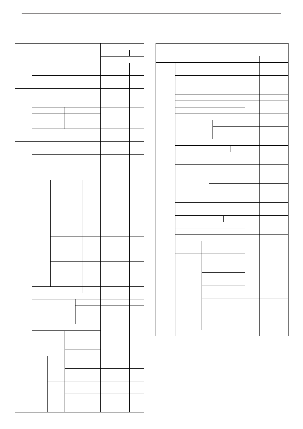
GH-CT9A
Item
SNDFZ
SJDFZ
SJGFZ
Minimum ground clearance m
0.140
¨
¨
Max. speed (estimated) km/h
180
¨
¨
Fuel consumption km/l (10/15 mode)
9.6
9.7
¨
Braking distance m (initial speed in
km/h) È
49 (100)
[Vehicle with
15-" brakes]
43 (100)
[Vehicle with
17" brakes]
¨
¨
Performance
Min. turning radius m
5.9
¨
¨
Bore x stroke mm
85.0 X 88.0
¨
¨
Compression ratio
8.8 (Unleaded
Premium)
¨
¨
Max. output net [k/W r.p.m.]
206 / 6500
(net)
¨
¨
Max. torque N•m/rpm.
392 / 3500
(net)
400 / 3500
(net) È
¨
Open
BTDC 21˚
BTDC 17˚
È
¨
Intake
Closed
ABDC 59˚
ABCD 63˚
È
¨
Open
BBDC 58˚
¨
¨
Engine
Valve or
port timing
Exhaust
Closed
ATDC 18˚
¨
¨
Fuel tank capacity (litres)
50
¨
55
Type and performance of ignition
equipment
Electronic:
-20˚~ 45˚
¨
¨
Type of spark plugs
IGR7A,
IGR7A-G,
S22PR-A7,
VW22PR-DA7
¨
¨
Battery capacity Ah
34 (5), 48 (5)
or 52 (5)
¨
¨
Electrical
Equipment
Alternator output V-A
12 – 58, 90,
100 or 105
¨
¨
TERIAL – MAIN SPECIFICATIONS / DETAILED SPECIFICATIONS
Detailed Specifications
8-4
These Detailed Specifications are based on submitted data, and may therefore dif
The
★ symbol indicates specifications which have changed from the previous model.
fer from the actual equipment.

8-5
GH-CT9A
Item
SNDFZ
SJDFZ
SJGFZ
1st2.785
2.909
¨
2nd1.950
1.944
¨
3rd1.444
1.434
¨
4th1.096
1.100
¨
5th0.825
0.868
¨
6th-
0.693
¨
Transmission
Gear ratio
Reverse
3.416
2.707
¨
Front
4.529
4.583
¨
Differential
Reduction
ratio
Rear
3.307
¨
¨
Power train
Transfer
Reduction
ratio
0.302
¨
¨
Main brake type
Hydraulic:
Front : Disc
Rear : Disc
¨
¨
Parking brake type
Mechanical
wheel brake
¨
¨
Front
MacPherson
¨
¨
Braking
system
Suspension
Rear
Multi-link
¨
¨
CO when
unloaded : %,
HC : ppm
CO: 0.1,
HC: 100
¨
¨
10/15 mode
g/km
CO: 0.67,
HC: 0.08,
NOx: 0.08
¨
¨
Emission
gas
suppression
equipment
Quantity or concentration
of exhaust gas
11 mode g/test
CO: 19.0,
HC: 2.20,
NOx: 1.40
¨
¨
REFERENCE MATERIAL – DETAILED SPECIFICATIONS
Main Equipment
4WD
RS
GSR
Equipment
5M/T
6M/T
Aluminium turbo
l
l
r
Intercooler water spray system
lll
W/out Intercooler water spray system
r
r
Engine
Engine oil cooler
lll
5-speed manual (short stroke, high gear
ratio)
l
6-speed manual (short stroke)
l
l
Gear lever
Leather
Front LSD
Helical
Rear LSD
Mechanical
lll
l
Active Centre Differential (ACD)
lll
Power
Train
Active Yaw Control Differential (AYC)
r
l
l
Bilstein shock absorbers
r
r
l
Front strut tower bars
lll
205/65R15 94H
l
Tyres
235/45ZR17
r
l
l
T125/70D16
l
Spare
tyre
T125/70D17
r
l
l
Steel (5-hole)
(Offset : 46 mm)
(PCD:
114.3mm)
15-inch
¥ 6.0JJ
silver
l
17-inch
¥ 8.0JJ
r
l
l
Steel (5-hole)
(Offset : 38 mm)
(PCD:
114.3mm)
17-inch
¥ 8.0JJ
(BBS)
rrr
Steel (5-hole)
(Offset : 40 mm)
(PCD:
114.3mm)
4.0T•
16-inch
l
Wheel
Steel (5-hole)
(Offset : 30 mm)
(PCD:
114.3mm)
4.0T•
17-inch
r
l
l
Centre cap
Black
l
Power steering
lll
MOMO
l
l
Steering wheel (leather
type ; 3-spoke; airbag)
MOMO
(black
spokes)
r
r
l
Tilt steering mechanism
Full cover
lll
Release switch
(gloss)
Parking brake
lever
Leather grip
l
15-inch ventilated
disc
l
Front
17-inch ventilated
disc (BREMBO)
r
l
l
15-inch ventilated
disc (drum in)
l
Drive
Control
Brake
Rear
16-inch ventilated
disc (drum in)
(BREMBO)
r
l
l
4WD
RS
GSR
Equipment
5M/T
6M/T
4 ABS (sports ABS)
r
l
l
Pressure control valve (PCV)
l
Drive
Control
Electronic Brake Force Distribution
System (EBD)
r
l
l
Central door locking
r
r
l
Boot lid opener
lll
Fuel filler flap opener
Child protection
lll
Multimode keyless entry
l
Black
l
l
Outer door handles
Body colour
l
Inside door handles
Coloured
lll
Power windows with safety mechanisms
r
r
l
Windscreen (laminated glass)
Green
Front door windows (UV absorbing
glass)
lll
Green
l
l
Green, with sun
shade
l
Rear window
glass (with
heating element)
Privacy glass
r
Green
lll
Rear door
windows
Privacy glass
r
Green
lll
Rear static
windows
Privacy glass
r
Bonnet
Aluminium
Air outlet
Wing
Aluminium
Roof
Aluminium
lll
Body
Rear end crossbar
l
l
Exclusive
front bumper
Body colour
Exclusive
rear bumper
Body colour
Windscreen
Rear window
Pillar, roof
Mouldings
(black)
Belt line
lll
Manual type (black)
l
l
Door mirror
Electric stowable
remote control door
mirror (body colour)
l
Front air dam
Exclusive
extension
Rear air dam
lll
Exterior
Rear spoiler (large size)
lll
REFERENCE MA
TERIAL – MAIN EQUIPMENT
8-6
The “●” symbol indicates standard equipment, and the “r” symbol indicates a manufacturer
’s option. The equipment may change, depending on the time of manufacture.
Note:
In the wheel columns, “PCD” is an abbreviation of “Pitch
Circle Diameter”, referring to the diameter of the pitch circle
of the installation holes.

8-7
4WD
RS
GSR
Equipment
5M/T
6M/T
Seat finish
Fabric
lll
Standard type
l
l
Recaro seat
r*1r
*1
l
Slide
Adjustment
mechanism
Reclining
lll
Front
Seat
Headrest
Low back bench seat (fixed)
l
l
High back bench seat (fixed)
Rear
Seat
Centre arm rest (with cup
holder)
l
2 ¥ 3-point with
ELR
With pre-tensioner
(driver’s seat &
front passenger
seat)
Front
Adjustable
seatbelt anchor
SRS
airbags
Rear
2 ¥ 3-point with
ELR / ALR + 1 ¥ 2-
point belt
lll
Driver’s seat
lll
SRS
airbags
Front passenger’s seat
r
r
l
Accessories box (1 DIN)
l
l
Parcel box (with lid)
l
Parcel
boxes
Coin box
Glove box
lll
Standard type
l
l
Large type
With lid
l
Shift boot ring
l
Front seat
lll
Ashtray
Rear seat
l
Floor
console
Cup holder (front seat)
lll
Centre panel (unique type)
l
l
2 DIN type
l
Headlining
Cloth
lll
Moulded type (soft)
Front door
trim
Door pocket (driver’s
seat, front passenger’s
seat)
Interior
Rear door
Moulded type (soft)
lll
4WD
RS
GSR
Equipment
5M/T
6M/T
Boot interior trim
Boot interior
floor carpet
Needle punch
l
¥ 1 (front passenger’s seat)
l
l
Retractable
assistance
straps
¥ 3 (front passenger’s seat,
rear seats)
l
Driver’s seat
lll
Front passenger’s seat
r
r
l
Ticket holder (driver’s seat)
lll
Sun
visors
Vanity mirror (with lid)
l
Internal
mirror
Day / night switchable
Interior
Foot rests
lll
44B20L
lll
Battery
55B24L
rrr
Halogen (low and
high beam)
l
l
Discharge (low
beam)
Halogen (high
beam)
Fog lamps
(halogen)
r
r
l
Position lights
lll
Automatic lights
l
Headlight levelling
r
r
l
Extension (black)
r
r
l
Rear combination
lights
(clear type *2)
lll
External
lights
Headlight
assembly
(Clear
type *2)
Extension (black)
r
r
l
High mount stop
light
Rear shelf mounting
(bulb type)
Front cabin lights (with map light)
lll
Rear cabin lights
lll
Interior
lights
Boot interior light
Combination meter
Special type
Electric type analogue
speedometer
Twin type trip meter
Tachometer
Water temperature
Meter
gauge
Fuel
lll
Fog lights
r
r
l
High beam
Turn signal and hazard lights
Equip-
ment
Indicator
lights
ACD
lll
Note :
*1
: 4-point seatbelt asymmetric type seat
*2
: Turn signal lamps coloured amber
REFERENCE MATERIAL – MAIN EQUIPMENT

REFERENCE MA
4WD
RS
GSR
Equipment
5/MT
6/MT
ABS
r
l
l
SRS airbags
Fuel level
Parking brake
Charge
Brake fluid
Engine check
Warning
lights
Door not properly closed
Lighting monitor warning
Buzzer
Ignition key reminder warning
l
l
l
Fixed time
intermittent
l
l
Variable
intermittent
(speed-
sensitive)
l
Windscre
en wipers
2 speed
Mist spray
Equip-
ment
Windscreen washer (synchronized with
wiper, 4-jet)
lll
4WD
RS
GSR
Equipment
5/MT
6/MT
Rear
window
wiper /
washer
Fixed time intermittent,
synchronized with (R) gear
position
l
AM/FM tuner radio + MD player
+ DVD-MMCS (DVD navigation
Mitsubishi Multi-Communication
System)
r
Roof aerial
lll
Roof and window aerial (diversity
aerial)
r
W/out audio
lll
Audio
parts
6 speakers (2 DIN compatible)
r
*3
Digital clock
Immobiliser system
lll
Manual heater
Air conditioning kit
l
l
Equip-
ment
Air
conditioning
Fully automatic air
conditioning
l
4WD
RS
GSR
Equipment
5M/T
6M/T
Battery
Weather strip silicon coating
Rear seat heater duct
Cold Climate Specification label
rrr
Door mirrors with heating elements
r
TERIAL – MAIN EQUIPMENT, COLD CLIMATE SPECIFICATIONS
8-8
Notes:
*3
: Brackets for an aerial and radio are installed as standard.
Cold Climate Specifications
 Loading...