

Page 1

GROUP 14
ENGINE COOLING
CONTENTS
14-1
GENERAL INFORMATION . . . . . . . . 14-2
SERVICE SPECIFICATIONS. . . . . . . 14-2
LUBRICANT. . . . . . . . . . . . . . . . . . . . 14-2
SEALANT. . . . . . . . . . . . . . . . . . . . . . 14-2
SPECIAL TOOLS. . . . . . . . . . . . . . . . 14-3
TROUBLESHOOTING . . . . . . . . . . . . 14-3
ON-VEHICLE SERVICE. . . . . . . . . . . 14-15
ENGINE COOLANT LEAK CHECK . . . . . . 14-15
RADIATOR CAP PRESSURE CHECK. . . . 14-15
ENGINE COOLANT REPLACEMENT . . . . 14-15
CONCENTRATION MEASUREMENT . . . . 14-16
FAN CONTROLLER CHECK . . . . . . . . . . . 14-16
FAN CONTROL RELAY CONTINUITY
CHECK . . . . . . . . . . . . . . . . . . . . . . . . . . . . 14-17
COOLING FAN MOTOR CHECK . . . . . . . . 14-17
THERMOSTAT . . . . . . . . . . . . . . . . . . 14-18
REMOVAL AND INSTALLATION . . . . . . . . 14-18
INSPECTION. . . . . . . . . . . . . . . . . . . . . . . . 14-19
WATER PUMP . . . . . . . . . . . . . . . . . . 14-20
REMOVAL AND INSTALLATION . . . . . . . . 14-20
WATER HOSE AND WATER PIPE . . 14-22
REMOVAL AND INSTALLATION . . . . . . . . 14-22
INSPECTION. . . . . . . . . . . . . . . . . . . . . . . . 14-23
RADIATOR . . . . . . . . . . . . . . . . . . . . . 14-24
REMOVAL AND INSTALLATION . . . . . . . . 14-24
Page 2
14-2
ENGINE COOLING
GENERAL INFORMATION
GENERAL INFORMATION
M1141000100456
The cooling system is designed to keep every part of
the engine at appropriate temperature in whatever
condition the engine may be operated. The cooling
method is of the water-cooled, pressure forced circu
lation type in which the water pump pressurizes coolant and circulates it throughout the engine. If the
engine coolant temperature exceeds the prescribed
temperature, the thermostat opens to circulate the
Item Specification
Radiator Performance kJ/h 216,700
coolant through the radiator as well so that the heat
absorbed by the coolant may be radiated into the air.
The water pump is of the centrifugal type and is
-
driven by the drive belt from the crankshaft. The radi
ator is the corrugated fin, down flow type. The cooling fan is controlled by the fan controller and
engine-ECU depend on driving conditions.
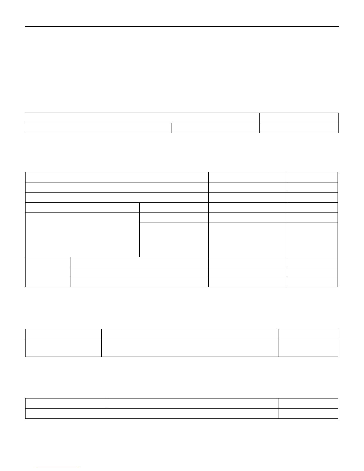
SERVICE SPECIFICATIONS
M1141000300483
Item Standard value Limit
Radiator cap pressure kPa 93 − 123 Minimum 83
Range of coolant antifreeze concentration of radiator % 30 − 60 -
Fan controller input voltage V Ignition switch: "ON" Battery positive voltage -
-
Fan controller output voltage V A/C switch: "OFF" 1 or less -
A/C switch: "ON" Repeat steps 1) and 2).
1) 8.2 ± 2.6
2) Battery positive voltage
± 2.6
Thermostat Valve opening temperature of thermostat °C 80 ± 1.5 -
Full-opening temperature of thermostat °C 93 -
Valve lift mm 9.5 or more -
-
LUBRICANT
M1141000400424
Item Specified lubricant Quantity L
Engine coolant (including
reserve tank)
DIA QUEEN SUPER LONG LIFE COOLANT or equivalent 6.0
SEALANT
M1141000500658
Item Specified sealant Remark
Cylinder block drain plug 3M Nut Locking Part No.4171 or equivalent Drying sealant
Page 3
ENGINE COOLING
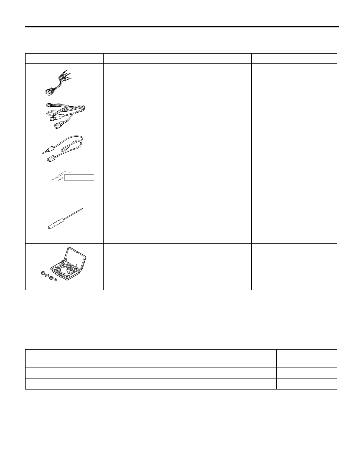
SPECIAL TOOLS
SPECIAL TOOLS
Tool Number Name Use
A
MB991223
A: MB991219
B: MB991220
C: MB991221
D: MB991222
B
C
Harness set
A: Check harness
B: LED harness
C: LED harness
adapter
D: Probe
Making voltage and
resistance measurement
during troubleshooting
A: Connector pin contact
B: Power circuit inspection
C: Power circuit inspection
D: Commercial tester
14-3
M1141000600592
pressure inspection
connection
D
DO NOT USE
MB991223
AZ
MB992006 Extra fine probe Making voltage and
MB992006
MB991871 LLC changer Coolant refilling
MB991871
TROUBLESHOOTING
INSPECTION CHART FOR TROUBLE
SYMPTOMS
Trouble symptom Inspection
Cooling fan does not operate 1
Cooling fan does not change speed or does not stop 2
M1141005600434
procedure No.
resistance measurement
during troubleshooting
Reference page
P.14-4
P.14-10
Page 4
14-4
ENGINE COOLING
TROUBLESHOOTING
INSPECTION PROCEDURE FOR
TROUBLE SYMPTOMS
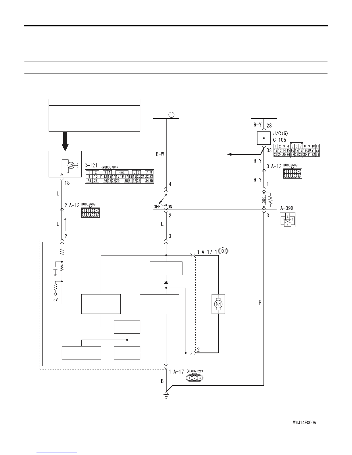
INSPECTION PROCEDURE 1: Cooling fan does not operate
Cooling fan drive circuit <L.H. drive vehicles>
INPUT SIGNAL
· A/C SWITCH
· ENGINE
COOLANT
TEMPERATURE
SENSOR
· VEHICLE SPEED
SENSOR
ENGINEECU
FUSIBLE
2
LINK
SMOOTHING
CIRCUIT
ENGINE
CONTROL
SYSTEM
ENGINE
CONTROL
RELAY
FAN
CONTROL
RELAY
INPUT SIGNAL
PROCESSING
TEMPERATURE
DETECTION
CURRENT
DETECTION
FAN CONTROLLER
Wire colour code
B : Black LG : Light green G : Green L : Blue W : White Y : Yellow SB : Sky blue
BR : Brown O : Orange GR : Grey R : Red P : Pink V : Violet PU : Purple
DRIVE
CIRCUIT
FIELD EFFECT
TRANSISTOR
CIRCUIT
RADIATOR
FAN
MOTOR
AC505138
AB
Page 5
ENGINE COOLING
TROUBLESHOOTING
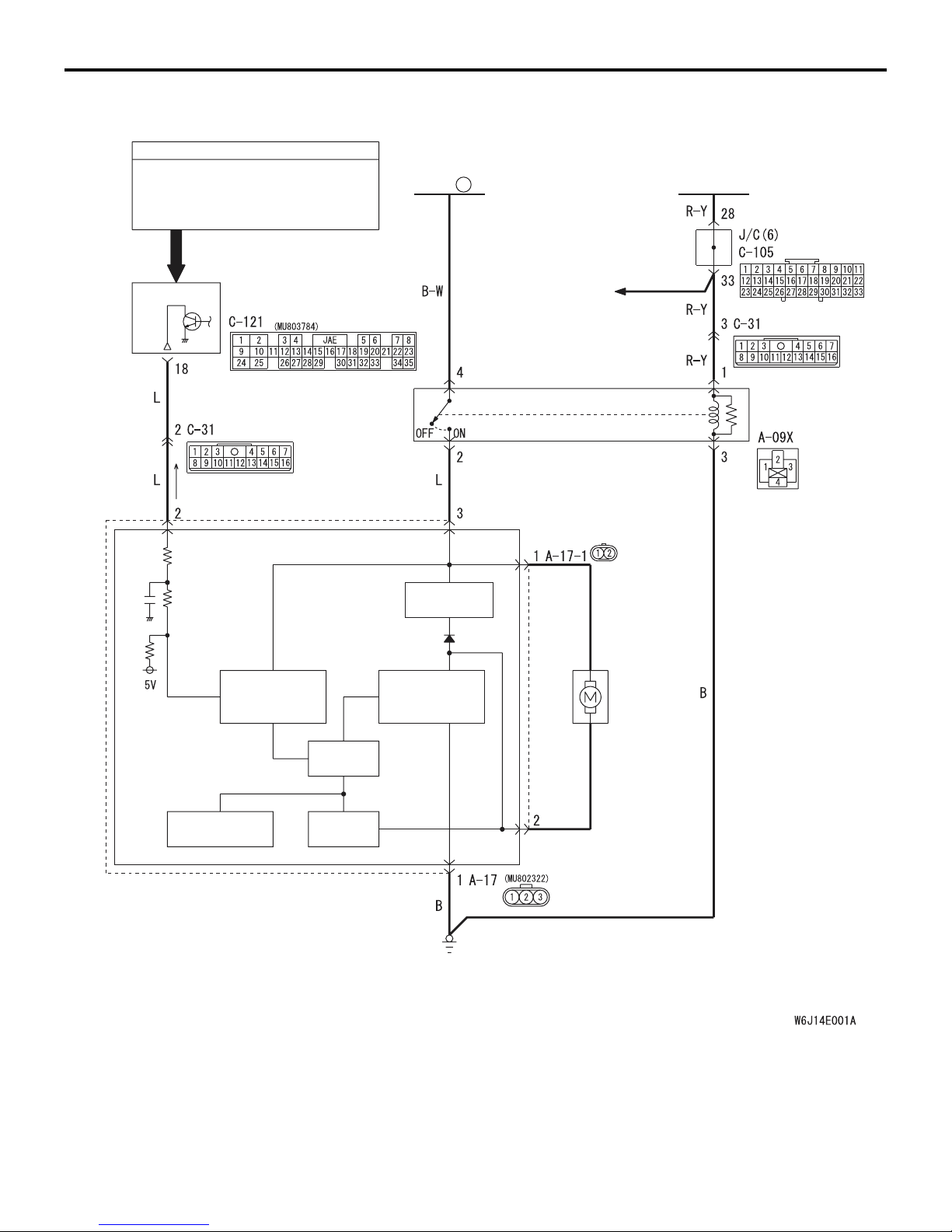
Cooling fan drive circuit <R.H. drive vehicles>
14-5
INPUT SIGNAL
· A/C SWITCH
· ENGINE
COOLANT
TEMPERATURE
SENSOR
· VEHICLE SPEED
SENSOR
ENGINEECU
FUSIBLE
2
LINK
SMOOTHING
CIRCUIT
ENGINE
CONTROL
SYSTEM
ENGINE
CONTROL
RELAY
FAN
CONTROL
RELAY
INPUT SIGNAL
PROCESSING
TEMPERATURE
DETECTION
DRIVE
CIRCUIT
CURRENT
DETECTION
FIELD EFFECT
TRANSISTOR
CIRCUIT
FAN CONTROLLER
Wire colour code
B : Black LG : Light green G : Green L : Blue W : White Y : Yellow SB : Sky blue
BR : Brown O : Orange GR : Grey R : Red P : Pink V : Violet PU : Purple
CIRCUIT OPERATION
• The fan controller is powered from fusible link
No.2.
RADIATOR
FAN
MOTOR
AC505139
AB
• The engine-ECU judges the required revolution
speed of cooling fan motor using the input signals
transmitted from A/C switch, vehicle speed sen
sor and engine coolant temperature sensor. The
engine-ECU activates the fan controller to drive
the cooling fan motor.
-
Page 6
14-6
ENGINE COOLING
TROUBLESHOOTING
TECHNICAL DESCRIPTION
• The cause could be a malfunction of the fan controller power supply or earth circuit.
• The cause could also be a malfunction of the fan
controller or the engine-ECU.
TROUBLESHOOTING HINTS
• Malfunction of fusible link
• Malfunction of fan control relay
• Malfunction of cooling fan motor
• Malfunction of fan controller
• Malfunction of engine-ECU
• Damaged wiring harness or connector
DIAGNOSIS
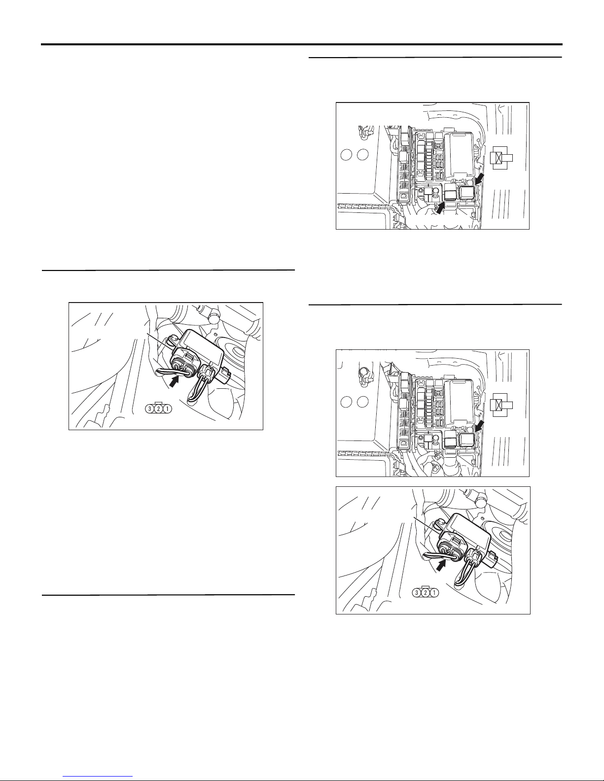
STEP 1. Check the circuit at fan controller
connector A-17 terminal 3.
Connector: A-17
Fan controller
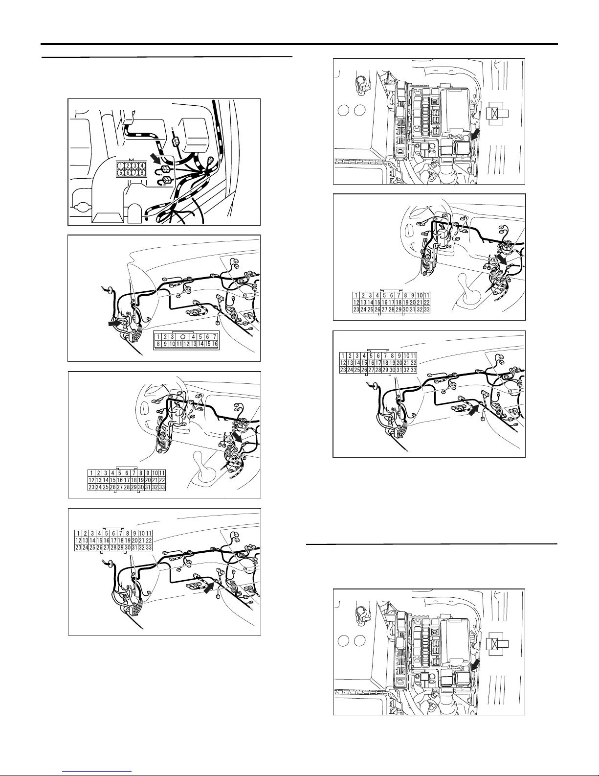
STEP 3. Check for harness damage between
fusible link No.2 and fan control relay connector
A-09X terminal 4.
Fusible link (2) And
Connector: A-09X
A-09X
3
2
4
1
Relay box
side
Fusible link (2)
AC310900
AC
Q: Are the harness wires between fusible link No.2
and fan control relay connector A-09X damaged?
YES : Repair or replace them, then go to Step 13.
NO : Go to Step 4.
STEP 4. Check for harness damage between fan
control relay connector A-09X terminal 2 and fan
controller connector A-17 terminal 3.
A-17 (GR)
Component side
AC210859
AD
(1) Disconnect fan controller connector A-17, and
measure at the harness side connector.
(2) Measure the voltage between terminal No.3 and
earth.
• When the ignition switch is turned to the "ON"
position, voltage should measure battery pos
itive voltage.
Q: Is the voltage battery positive voltage when the
ignition switch is turned to the "ON" position?
YES : Go to Step 7.
NO : Go to Step 2.
STEP 2. Check the fan control relay.
Refer to P.14-17.
Q: Is the fan control relay in good condition?
YES : Go to Step 3.
NO : Replace it, then go to Step 1.
Connector: A-09X
A-09X
3
4
1
Relay box
side
AC310900
Connector: A-17
-
Fan controller
A-17 (GR)
Component side
Q: Are the harness wires between fan control relay
connector A-09X terminal 2 and fan controller
connector A-17 terminal 3 damaged?
YES : Repair or replace them, then go to Step 13.
NO : Go to Step 5.
AC210859
2
AB
AD
Page 7
ENGINE COOLING
TROUBLESHOOTING
14-7
STEP 5. Check for harness damage between J/C
(6) C-105 and fan control relay connector A-09X.
NOTE:
Connector: A-13 <LHD>
A-13 (B)
AC210877
Connector: C-31 <RHD>
C-31
AC
Connector: A-09X
Connector: C-105 <LHD>
Connector: C-105 <RHD>
A-09X
4
Relay box
side
AC310900
C-105
AC310901
3
2
1
AB
AB
AC310903
AB
Connector: C-105 <LHD>
C-105
AC310901
AB
Connector: C-105 <RHD>
C-105
AC310902
AB
After inspecting intermediate connector A-13 <LHD>
terminal 3, intermediate connector C-31 <RHD> ter
minal 12 and J/C (6) C-105 terminal 28, 33 inspect
the wires. If intermediate connector A-13 <LHD>,
C-31<RHD> and J/C (6) C-105 are damaged, repair
or replace them. Refer to GROUP 00, How to Use
Troubleshooting/Inspection Service Points
P.00-5.
C-105
AC310902
AB
Q: Are the harness wires between J/C (6) C-105
terminal 28 and fan control relay connector A-09X
terminal 1 damaged?
YES : Repair or replace them, then go to Step 13.
NO : Go to Step 6.
STEP 6. Check for harness damage between fan
control relay connector A-09X terminal 3 and
earth.
Connector: A-09X
A-09X
3
2
4
1
Relay box
side
AC310900
AB
Page 8
14-8
ENGINE COOLING
TROUBLESHOOTING
Q: Are the harness wires between fan control relay
connector A-09X terminal 3 and earth damaged?
YES : Repair or replace them, then go to Step 13.
NO : Go to Step 7.
STEP 7. Check the cooling fan motor.
Refer to P.14-17.
Q: Is the cooling fan motor in good condition?
YES : Go to Step 8.
NO : Replace it, then go to Step 13.
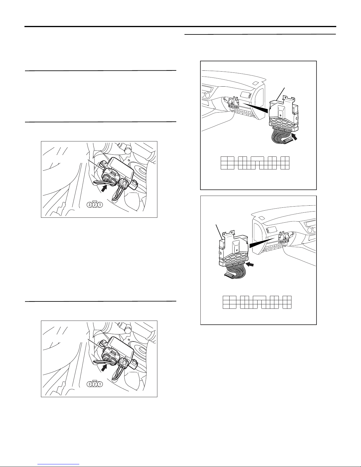
STEP 8. Check the circuit at fan controller
connector A-17 terminal 1.
Connector: A-17
Fan controller
A-17 (GR)
STEP 10. Measure the output circuit voltage at
engine-ECU connector C-121 terminal 18 by
backprobing.
Connector: C-121 <LHD>
Engine-ECU
C-121 (GR)
1924
10
11312
24
25
Connector: C-121 <RHD>
JAE
16
13
1415
26
1718
2829
27
3031
Harness side
6205
19 21
3332
8237
22
35
34
AC505254
AB
Component side
AC210859
AD
(1) Disconnect fan controller connector A-17, and
measure at the harness side connector.
(2) Measure the resistance between terminal No.1
and earth.
• The resistance should measure less than 2
ohms.
Q: Is the resistance less than 2 ohms?
YES : Go to Step 10.
NO : Go to Step 9.
STEP 9. Check the harness wire between fan
controller connector A-17 and earth.
Connector: A-17
Fan controller
A-17 (GR)
Engine-ECU
C-121 (GR)
1924
10
11312
24
25
JAE
16
13
1415
26
2829
27
1718
3031
6205
19 21
3332
8237
22
35
34
Harness side
AC505255
AB
(1) Do not disconnect engine-ECU connector C-121.
(2) Start the engine and allow it to idle.
(3) Turn the A/C switch to the "ON" position.
(4) Measure the voltage between terminal No.18 and
earth by backprobing.
• The voltage should measure 0.7 volt or more
when the cooling fan is operating.
Component side
Q: Are the harness wires between fan controller
connector A-17 and earth damaged?
YES : Repair or replace them, then go to Step 13.
NO : Go to Step 10.
AC210859
AD
Q: Is the voltage 0.7 volt or more when the cooling fan
is operating?
YES : Go to Step 12.
NO : Go to Step 11.
Page 9

ENGINE COOLING
TROUBLESHOOTING
14-9
STEP 11. Check the harness wire between
engine-ECU connector C-121 and fan controller
connector A-17.
NOTE:
Connector: A-13 <LHD>
A-13 (B)
AC210877
Connector: C-31 <RHD>
C-31
AC
Connector: C-121 <LHD>
56
3233 30
31
JAE
161819 1720
15
29
42
78
222123
34
35
Component side
Connector: C-121 <RHD>
Engine-ECU
Engine-ECU
3
11 10121314
24
262827 25
C-121 (GR)
1
9
AC505254
AC
AC310903
AB
If intermediate connector A-13 <LHD> terminal 2 and
intermediate connector C-31 <RHD> terminal 14 is
damaged, repair or replace it. Refer to GROUP 00,
How to Use Troubleshooting/Inspection Service
Points
P.00-5.
C-121 (GR)
6
3233 30
JAE
15
161819 1720
29
42
3
11 10121314
262827 25
1
9
24
5
31
78
222123
34
35
Component side
AC505255
AC
Connector: A-17
Fan controller
A-17 (GR)
Component side
AC210859
AD
Q: Are the harness wires between engine-ECU
connector C-121 terminal 18 and fan controller
connector A-17 terminal 2 damaged?
YES : Repair or replace them, then go to Step 13.
NO : Go to Step 12.
Page 10

14-10
ENGINE COOLING
TROUBLESHOOTING
STEP 12. Check the fan controller at engine-ECU
connector C-121.
Connector: C-121 <LHD>
Engine-ECU
C-121 (GR)
1924
10
11312
24
25
Connector: C-121 <RHD>
JAE
16
13
1415
26
1718
2829
27
3031
Harness side
6205
19 21
3332
8237
22
35
34
AC505254
AB
(2) Pull out terminal No.18.
(3) Turn the ignition switch to the "ON" position.
Q: Does the cooling fan motor operate?
YES : Replace the engine-ECU. Then go to Step
.
13
NO : Replace the fan controller. Then go to Step
.
13
STEP 13. Check the symptoms.
Q: Does the cooling fan operate correctly?
YES : The procedure is complete.
NO : Return to Step 1.
Engine-ECU
C-121 (GR)
1924
10
11312
24
25
JAE
16
13
1415
26
2829
27
1718
3031
6205
19 21
3332
8237
22
35
34
Harness side
AC505255
AB
(1) Do not disconnect engine-ECU connector C-121.
INSPECTION PROCEDURE 2: Cooling fan does not change speed or does not stop
NOTE: If the engine coolant temperature reaches 110°C or higher, the cooling fan control runs the cooling fan
for up to 5 minutes even after the ignition switch is turned to the "LOCK" (OFF) position (the fan stops its rota
tion when the engine coolant temperature decreases to 110°C or lower).
COOLING FAN DRIVE CIRCUIT
Refer to P.14-4.
CIRCUIT OPERATION
• The fan controller is powered from fusible link
No.2.
• The engine-ECU judges the required revolution
speed of cooling fan motor using the input signals
transmitted from A/C switch, vehicle speed sen
sor and engine coolant temperature sensor. The
engine-ECU activates the fan controller to drive
the cooling fan motor.
-
-
Page 11

ENGINE COOLING
TROUBLESHOOTING
14-11
TECHNICAL DESCRIPTION
• The fan controller has variable control of the cooling fan motor speed using signals transmitted
from the engine-ECU.
TROUBLESHOOTING HINTS
• Malfunction of fan control relay
• Malfunction of fan controller
• Malfunction of engine-ECU
DIAGNOSIS
STEP 1. Check the fan control relay.
Refer to P.14-17.
Q: Is the fan control relay in good condition?
YES : Go to Step 2.
NO : Replace the part, then go to Step 8.
STEP 2. Check the harness wire between fan
control relay connector A-09X terminal 2 and fan
controller connector A-17 terminal 3.
STEP 3. Measure the output circuit voltage at
engine-ECU connector C-121 terminal 18 by
backprobing.
Connector: C-121 <LHD>
Engine-ECU
C-121 (GR)
1924
10
11312
24
25
Connector: C-121 <RHD>
JAE
16
13
1415
26
1718
2829
27
3031
Harness side
6205
19 21
3332
8237
22
35
34
AC505254
AB
Connector: A-09X
A-09X
3
2
4
1
Relay box
side
AC310900
AB
Connector: A-17
Fan controller
A-17 (GR)
Component side
AC210859
AD
Q: Are the harness wire between fan control relay
connector A-09X and fan controller connector A-17
damaged?
YES : Repair or replace the part, then go to Step
6
.
NO : Go to Step 3.
Engine-ECU
C-121 (GR)
1924
10
11312
24
25
JAE
16
13
1415
26
2829
27
1718
3031
6205
19 21
3332
8237
22
35
34
Harness side
AC505255
AB
(1) Do not disconnect engine-ECU connector C-121.
(2) Start the engine and allow it to idle.
(3) Measure the voltage between terminal No.18 and
earth by backprobing.
• The voltage should measure less than 0.3 volt
when the cooling fan is not operating.
Q: Is the voltage less than 0.3 volt when the cooling
fan is not operating?
YES : Go to Step 6.
NO : Go to Step 4.
Page 12

14-12
ENGINE COOLING
TROUBLESHOOTING
STEP 4. Measure the output circuit voltage at
engine-ECU connector C-121 terminal 18 by
backprobing.
Connector: C-121 <LHD>
Engine-ECU
C-121 (GR)
1924
10
11312
24
25
Connector: C-121 <RHD>
JAE
16
13
1415
26
1718
2829
27
3031
Harness side
6205
19 21
3332
8237
22
35
34
AC505254
AB
(2) Start the engine and allow it to idle.
(3) Turn the A/C switch to the "ON" position.
(4) Measure the voltage between terminal No.18 and
earth by backprobing.
• The voltage should measure 0.7 volt or more
when the cooling fan is operating.
Q: Is the voltage 0.7 volt or more when the cooling fan
is operating?
YES : Go to Step 6.
NO : Go to Step 5.
Engine-ECU
C-121 (GR)
1924
10
11312
24
25
JAE
16
13
1415
26
2829
27
1718
3031
6205
19 21
3332
8237
22
35
34
Harness side
AC505255
AB
(1) Do not disconnect engine-ECU connector C-121.
Page 13

ENGINE COOLING
TROUBLESHOOTING
14-13
STEP 5. Check the harness wire between
engine-ECU connector C-121 and fan controller
connector A-17.
NOTE:
Connector: A-13 <LHD>
A-13 (B)
AC210877
Connector: C-31 <RHD>
C-31
AC
Connector: C-121 <LHD>
56
3233 30
31
JAE
161819 1720
15
29
42
78
222123
34
35
Component side
Connector: C-121 <RHD>
Engine-ECU
Engine-ECU
3
11 10121314
24
262827 25
C-121 (GR)
1
9
AC505254
AC
AC310903
AB
If intermediate connector A-13 <LHD> terminal 2 and
intermediate connector C-31 <RHD> terminal 14 is
damaged, repair or replace it. Refer to GROUP 00,
How to Use Troubleshooting/Inspection Service
Points
P.00-5.
C-121 (GR)
6
3233 30
JAE
15
161819 1720
29
42
3
11 10121314
262827 25
1
9
24
5
31
78
222123
34
35
Component side
AC505255
AC
Connector: A-17
Fan controller
A-17 (GR)
Component side
AC210859
AD
Q: Are the harness wires between engine-ECU
connector C-121 terminal 18 and fan controller
connector A-17 terminal 2 damaged?
YES : Repair or replace them, then go to Step 8.
NO : Go to Step 6.
Page 14

14-14
ENGINE COOLING
TROUBLESHOOTING
STEP 6. Check the fan controller at engine-ECU
connector C-121.
Connector: C-121 <LHD>
Engine-ECU
C-121 (GR)
1924
10
11312
24
25
Connector: C-121 <RHD>
JAE
16
13
1415
26
1718
2829
27
3031
Harness side
6205
19 21
3332
8237
22
35
34
AC505254
AB
STEP 7. Check the fan controller at engine-ECU
connector C-121.
Connector: C-121 <LHD>
Engine-ECU
C-121 (GR)
1924
10
11312
24
25
Connector: C-121 <RHD>
JAE
16
13
1415
26
1718
2829
27
3031
Harness side
6205
19 21
3332
8237
22
35
34
AC505254
AB
Engine-ECU
C-121 (GR)
1924
10
11312
24
25
JAE
16
13
1415
26
2829
27
1718
3031
6205
19 21
3332
8237
22
35
34
Harness side
AC505255
AB
(1) Do not disconnect engine-ECU connector C-121.
(2) Pull out terminal No.18.
(3) Turn the ignition switch to the "ON" position.
Q: Does the cooling fan motor operate?
YES : Replace the engine-ECU. Then go to Step
8
.
NO : Go to Step 7.
Engine-ECU
C-121 (GR)
1924
10
11312
24
25
JAE
16
13
1415
26
2829
27
1718
3031
6205
19 21
3332
8237
22
35
34
Harness side
AC505255
AB
(1) Disconnect engine-ECU connector C-121.
(2) Pull out terminal No.18.
(3) Connect terminal No.18 to the body earth.
(4) Turn the ignition switch to the "ON" position.
Q: Does the cooling fan motor stop running?
YES : Replace the engine-ECU. Then go to Step
.
8
NO : Replace the fan controller. Then go to Step
8
.
STEP 8. Check the symptoms.
Q: Does the cooling fan operate correctly?
YES : The procedure is complete.
NO : Return to Step 1.
Page 15

ENGINE COOLING
ON-VEHICLE SERVICE
ON-VEHICLE SERVICE
14-15
ENGINE COOLANT LEAK CHECK
M1141001000388
WARNING
When pressure testing the cooling system,
slowly release cooling system pressure to
avoid getting burned by hot coolant.
CAUTION
• Be sure to completely clean away any moisture from the places checked.
• When the tester is taken out, be careful not to
spill any coolant.
•
Be careful when installing and removing the
tester and when testing not to deform the
filler neck of the radiator.
Cap adapter
Adapter
Minimum limit: 83 kPa
Standard value: 93 − 123 kPa
3. Replace the radiator cap if the reading does not
remain at or above the minimum limit.
ENGINE COOLANT REPLACEMENT
M1141001200553
1. Remove the under cover (Refer to GROUP 51,
Front Bumper
WARNING
When removing the radiator cap, use care to
avoid contact with hot coolant or steam.
Place a shop towel over the cap and turn the
cap anti-clockwise a little to let the pressure
escape through the vinyl tube. After relieving
the steam pressure, remove the cap by
slowly turning it anti-clockwise.
2. Drain the water from the radiator, heater core and
engine after unplugging the radiator drain plug
and removing the radiator cap.
P.51-2).
ACX01844
AB
1. Check that the coolant level is up to the filler neck.
Install a radiator tester and apply 160 kPa
pressure, and then check for leakage from the
radiator hose or connections.
2. If there is leakage, repair or replace the
appropriate part.
RADIATOR CAP PRESSURE CHECK
M1141001300453
NOTE: Be sure that the cap is clean before testing.
Rust or other foreign material on the cap seal will
cause an improper reading.
Cap adapter
AC211643 AB
1. Use a cap adapter to attach the cap to the tester.
2. Increase the pressure until the indicator of the
gauge stops moving.
Water inlet pipe
44 ± 5 N·m
AC210639
AB
3. Drain the water in the water jacket by unplugging
the drain plug of the cylinder block.
4. Remove the reserve tank and drain the coolant.
5. Drain the cooling water then clean the path of the
cooling water by injecting water into the radiator
from the radiator cap area.
Page 16

14-16
ENGINE COOLING
ON-VEHICLE SERVICE
6. Apply the designated sealant to the screw area of
the cylinder block drain plug, and then tighten to
the standard torque.
Specified sealant: 3M Nut Locking Part
No.4171 or equivalent
Tightening torque: 44 ± 5 N⋅m
7. Securely tighten the drain plug of the radiator.
8. Assemble the reserve tank.
CAUTION
Do not use alcohol or methanol anti-freeze or any
engine coolants mixed with alcohol or methanol
anti-freeze. The use of an improper anti-freeze
can cause corrosion of the aluminium compo
-
nents.
MB991871
Air hose
AC210658
AB
9. By referring to the section on coolant, select an
appropriate concentration for safe operating
temperature within the range of 30 to 60 %. Use
special tool LLC changer (MB991871) to refill the
coolant. A convenient mixture is a 50 % water and
50 % antifreeze solution (freezing point:
−31°C).
Recommended antifreeze: DIA QUEEN SUPER
LONG LIFE COOLANT or equivalent
Quantity: 6.0 L
NOTE: For how to use the special tool, refer to its
manufacturer’s instructions.
10.Reinstall the radiator cap.
11.Start the engine and let it warm up until the
thermostat opens.
12.Repeatedly revving the engine up to 3,000 r/min
several times, then stop the engine.
13.Remove the radiator cap after the engine has
become cold, and pour in coolant up to the brim.
Reinstall the cap.
CAUTION
Do not overfill the reserve tank.
14.Add coolant to the reserve tank between the
"FULL" and "LOW" mark if necessary.
15.Install the under cover (Refer to GROUP 51,
Front Bumper
P.51-2).
CONCENTRATION MEASUREMENT
M1141001100448
Measure the temperature and specific gravity of the
engine coolant to check the antifreeze concentration.
Standard value: 30 − 60 % (allowable concen-
tration range)
Recommended antifreeze: DIA QUEEN SUPER
LONG LIFE COOLANT or equivalent
CAUTION
If the concentration of the anti-freeze is below 30
%, the anti-corrosion property will be adversely
affected. In addition, if the concentration is
above 60 %, both the anti-freezing and engine
cooling properties will decrease, affecting the
engine adversely. For these reasons, be sure to
maintain the concentration level within the speci
fied range.
FAN CONTROLLER CHECK
M1141006100238
1. Remove the centre under cover (Refer to GROUP
51, Front Bumper
Fan controller
connector:
Component
side
23 1
2. Disconnect the fan controller connector.
3. Turn the ignition switch to the "ON" position, and
measure the voltage between the harness-side
connector terminals.
Standard value: Battery positive voltage
4. Turn the ignition switch to the "LOCK" (OFF)
position, and connect the fan controller connector.
P.51-2).
Fan controller
AC210945
AB
-
Page 17

Fan controller
MB991222
Circuit tester
Cooling fan motor
connector:
Harness side
ENGINE COOLING
ON-VEHICLE SERVICE
FAN CONTROL RELAY CONTINUITY
CHECK
Battery
14-17
M1141006200354
AC210667
AB
5. Insert special tool probe (MB991222) at the back
of the cooling fan motor connector.
6. Connect the special tool to the circuit tester.
7. Ensure that the A/C switch is off, and start the
engine and run it at idle.
8. Measure the voltage between the cooling fan
motor connector terminals.
Standard value: 1V or less
9. Turn the A/C switch to the "ON" position.
WARNING
Stay clear of the fan when the fan starts running.
10. Measure the voltage between the cooling fan
motor connector terminals while the fan is
running. The voltage should repeat the values 1)
and 2) below.
Standard value:
1) 8.2 ± 2.6 V
2) Battery positive voltage ± 2.6 V
11.If the voltage does not repeatedly change as
indicated, replace the fan controller.
12.Install the centre under cover (Refer to GROUP
51, Front Bumper
P.51-2).
4
2
3
1
AC210672
Continuity test
results
AB
Battery
voltage
2
13
4
Terminal No.to
be connected to
tester
Not applied 4 − 2 Open circuit
• Connect
4 − 2 Less than 2 ohms
terminal
No.1 and
battery
(+)
terminal.
• Connect
terminal
No.3 and
battery
−)
(
terminal.
COOLING FAN MOTOR CHECK
M1141007100134
1. Remove the centre under cover (Refer to GROUP
51, Front Bumper
P.51-2).
Page 18

14-18
ENGINE COOLING
THERMOSTAT
Cooling fan
motor
connector:
Component side
Cooling fan motor
AC210668
AB
2. Remove the cooling fan motor connector.
THERMOSTAT
REMOVAL AND INSTALLATION
M1141002400884
Pre-removal Operation
• Under Cover Removal (Refer to GROUP 51, Front
Bumper
• Engine Coolant Draining (Refer to P.14-15).
• Intake Air Duct Removal (Refer to GROUP 15, Air
Cleaner
• Air Hose E, Air Pipe C and Air Hose D Removal (Refer to
GROUP 15, Intercooler
P.51-2).
P.15-5).
P.15-6).
WARNING
Stay clear of the fan when the fan starts running.
3. Check to see that the fan motor of the radiator
turns when applying battery power between the
connector terminals of the cooling fan motor. Also
check to see that there is no abnormal sound
coming from the cooling fan motor at this time.
4. If the cooling fan motor is defective, replace it.
5. Install the centre under cover (Refer to GROUP
51, Front Bumper
Post-installation Operation
• Air Hose E, Air Pipe C and Air Hose D Installation (Refer
to GROUP 15, Intercooler
• Intake Air Duct Installation (Refer to GROUP 15, Air
Cleaner
• Engine Coolant Refilling (Refer to P.14-15).
• Under Cover Installation (Refer to GROUP 51, Front
Bumper
P.15-5).
P.51-2).
P.51-2).
P.15-6).
10 ± 1 N·m
5
6
7
8
4
5.0 ± 1.0 N·m
11 ± 1 N·m
2
1
11 ± 1 N·m
3
Removal steps
1. Accelerator cable connection <LH
drive vehicles>
2. Control wiring harness connection
<<A>> >>B<<
AC504958
Removal steps (Continued)
3. Vacuum hose and pipe assembly
4. Radiator upper hose connection
5. Wiring harness clamp
AB
Page 19

ENGINE COOLING
THERMOSTAT
14-19
Removal steps (Continued)
6. Harness bracket
7. Water outlet fitting
>>A<<
8. Thermostat
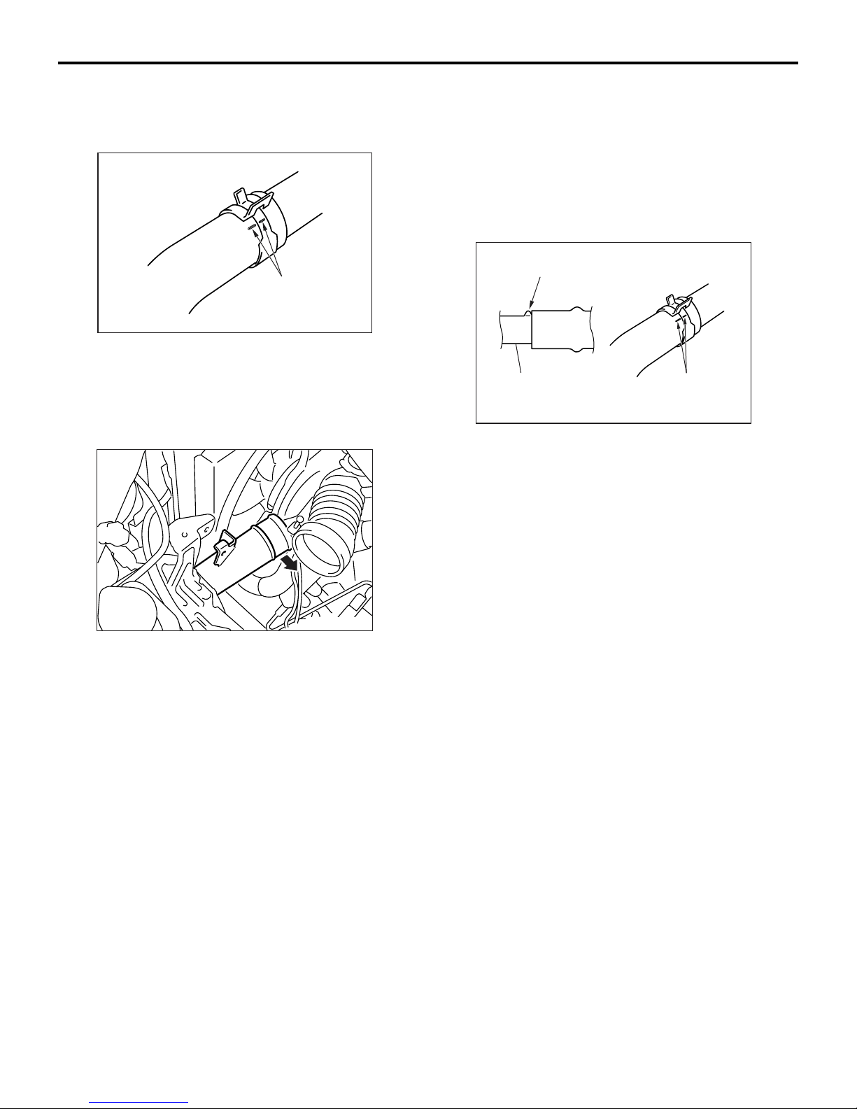
REMOVAL SERVICE POINT
<<A>> RADIATOR UPPER HOSE DISCON-
NECTION
Mating marks
AC200641AB
Make mating marks on the radiator hose and the
hose clamp. Disconnect the radiator hose.
INSTALLATION SERVICE POINTS
>>A<< THERMOSTAT INSTALLATION
1. Insert each hose as far as the projection of the
water outlet fitting.
2. Align the mating marks on the radiator hose and
hose clamp, and then connect the radiator hose.
INSPECTION
M1141002500494
THERMOSTAT CHECK
ACX00400
1. Immerse the thermostat in water, and heat the
water while stirring. Check the thermostat valve
opening temperature.
Standard value:
Valve opening temperature: 80 ± 1.5°C
CAUTION
Make absolutely sure that no oil is adhering to
the rubber ring of the thermostat. In addition, be
careful not to fold over or scratch the rubber ring
when inserting. If the rubber ring is damaged,
replace the thermostat.
Install the thermostat being careful not to fold over or
scratch the rubber ring.
>>B<< RADIATOR UPPER HOSE
CONNECTION
Projection
Water outlet fitting
Mating marks
AC200642
AB
Valve lift
ACX00401
AB
2. Check that the amount of valve lift is at the
standard value when the water is at the
full-opening temperature.
NOTE: Measure the valve height when the thermostat is fully closed, and use this measurement
to compare the valve height when the thermostat
is fully open.
Standard value:
Full-opening temperature: 93°C
Amount of valve lift: 9.5 mm or more
Page 20

14-20
ENGINE COOLING
WATER PUMP
WATER PUMP
REMOVAL AND INSTALLATION
M1141002701004
CAUTION
If the vehicle is equipped with the Brembo™ disc brake, during maintenance, take care not to contact
the caliper with tools or parts, because the caliper paint will be scratched.
Pre-removal Operation
• Under Cover Removal (Refer to GROUP 51, Front
Bumper
• Engine Coolant Draining (Refer to P.14-15).
• Timing Belt Tensioner Adjuster Removal (Refer to
GROUP 11A, Timing Belt
P.51-2).
24 ± 4 N·m
20 ± 2 N·m
P.11A-36).
22 ± 4 N·m
N
4
1
Post-installation Operation
• Timing Tensioner Adjuster Belt Installation (Refer to
GROUP 11A, Timing Belt
• Engine Coolant Refilling (Refer to P.14-15).
• Under Cover Installation (Refer to GROUP 51, Front
Bumper
P.51-2).
P.11A-36).
23 ± 3 N·m
14 ± 1 N·m
2
Removal steps
1. Alternator brace
2. Water pump
Bolt specifications
8 × 60
N
3
8 × 22
8 × 14
2
8 × 55
8 × 22
Nominal diameter × Nominal length mm
AC406755
>>A<<
AC504976
Removal steps (Continued)
3. Water pump gasket
4. O-ring
AB
Page 21

ENGINE COOLING
WATER PUMP
14-21
INSTALLATION SERVICE POINT
>>A<< O-RING INSTALLATION
CAUTION
Do not let the O-ring get contaminated with
grease or engine oil.
Water pump
O-ring
Water inlet pipe
AC103005
AC
Fit an O-ring into the O-ring groove located at the
end of the water inlet pipe and apply water to the
O-ring or the inside of the mounting surface of the
water pump for insertion.
Page 22

14-22
ENGINE COOLING
WATER HOSE AND WATER PIPE
WATER HOSE AND WATER PIPE
REMOVAL AND INSTALLATION
M1141003301076
Pre-removal Operation
• Under Cover Removal (Refer to GROUP 51, Front
Bumper
• Engine Coolant Draining (Refer to P.14-15).
• Battery and Battery Tray Removal
• Air Cleaner Assembly Removal (Refer to GROUP 15, Air
Cleaner
• Turbocharger Bypass Valve Assembly, Air By-pass Hose,
Air Hose E, Air Pipe C and Air Hose D Removal (Refer to
GROUP 15, Intercooler
• Thermostat Removal (Refer to P.14-18).
11
N
P.51-2).
P.15-5).
P.15-6).
12
13
13 ± 2 N·m
9
16
Post-installation Operation
• Thermostat Installation (Refer to P.14-18).
• Turbocharger Bypass Valve Assembly, Air By-pass Hose,
• Air Cleaner Assembly Installation (Refer to GROUP 15,
• Battery and Battery Tray Installation
• Engine Coolant Refilling (Refer to P.14-15).
• Under Cover Installation (Refer to GROUP 51, Front
N
10
5.0 ± 1.0 N·m
Air Hose E, Air Pipe C and Air Hose D Installation (Refer
to GROUP 15, Intercooler
Air Cleaner
Bumper
P.15-5).
P.51-2).
P.15-6).
11 ± 1 N·m
2
8
4
6
1
23 ± 4 N·m
3
<<A>> >>C<<
>>A<<
15
10 ± 1 N·m
Removal steps
1. Wiring harness clamp
2. Harness bracket
3. Engine coolant temperature gauge
unit connector
4. Engine coolant temperature
sensor connector
5. Water feed hose
6. Thermostat case assembly
7. Thermostat case gasket
8. Radiator lower hose connection
9. Detonation sensor connection
10. O-ring
11. Water feed hose
42 ± 7 N·m
19
20
N
>>B<<
>>A<<
7
N
14
5
10 ± 1 N·m
17
42 ± 7 N·m
N
18
AC504959
Removal steps (Continued)
12. Water return hose
13. Heater hose connection
14. Water return hose
15. Water inlet pipe
16. O-ring
17. Turbocharger water feed pipe
18. Gaskets
Turbocharger and exhaust fitting
•
assembly (Refer to GROUP 15,
Exhaust Manifold and
Turbocharger
19. Turbocharger water return pipe
20. Gaskets
P.15-10).
AB
Page 23

ENGINE COOLING
WATER HOSE AND WATER PIPE
14-23
REMOVAL SERVICE POINT
<<A>> RADIATOR LOWER HOSE DIS-
CONNECTION
Mating marks
AC200641AB
Make mating marks on the radiator hose and the
hose clamp. Disconnect the radiator hose.
INSTALLATION SERVICE POINTS
>>A<< O-RING INSTALLATION
CAUTION
Do not let the O-ring get contaminated with
grease or engine oil.
Water pump
>>B<< WATER INLET PIPE
INSTALLATION
Temporarily install the water inlet pipe. After installing
the water outlet fitting and thermostat case assembly,
tighten the mounting bolt of the water inlet pipe to the
specified torque.
Tightening torque
M6 bolt: 5.0 ± 1.0 N⋅m
M8 bolt: 13 ± 2 N⋅m
>>C<< RADIATOR LOWER
HOSE/RADIATOR UPPER HOSE
CONNECTION
Projection
Water inlet pipe or
water outlet fitting
Mating
marks
AC200642
AD
O-ring
Water inlet pipe
AC103005
AC
Fit an O-ring into the O-ring groove located at the
end of the water inlet pipe and apply water to the
O-ring or the inside of the mounting surface of the
water pump for insertion.
1. Insert each hose as far as the projection of the
water inlet pipe or water outlet fitting.
2. Align the mating marks on the radiator hose and
hose clamp, and then connect the radiator hose.
INSPECTION
M1141003400360
WATER PIPE AND HOSE CHECK
Check the water pipe and hose for cracks, damage
and clogs. Replace them if necessary.
Page 24

14-24
ENGINE COOLING
RADIATOR
RADIATOR
REMOVAL AND INSTALLATION
M1141001501193
Pre-removal Operation
• Under Cover Removal (Refer to GROUP 51, Front
Bumper
• Engine Coolant Draining (Refer to P.14-15).
• Battery and Battery Tray Removal
• Air Cleaner Assembly Removal (Refer to GROUP 15, Air
Cleaner
• Air Hose E, Air Pipe C and Air Hose D Removal (Refer to
GROUP 15, Intercooler
P.51-2).
P.15-5).
12 ± 2 N·m
11
P.15-6).
12 ± 2 N·m
3
13
Post-installation Operation
• Air Hose E, Air Pipe C and Air Hose D Installation (Refer
11
to GROUP 15, Intercooler
• Air Cleaner Assembly Installation (Refer to GROUP 15,
Air Cleaner
• Battery and Battery Tray Installation
• Engine Coolant Refilling (Refer to P.14-15).
• Under Cover Installation (Refer to GROUP 51, Front
Bumper
P.15-5).
P.51-2).
5.0 ± 1.0 N·m
4
P.15-6).
6
7
9
5
5.0 ± 1.0 N·m
N
2
1
5.0 ± 1.0 N·m
8
<<A>> >>A<<
<<A>> >>A<<
<<B>>
14
10
12 ± 2 N·m
12
Radiator removal steps
1. Radiator drain plug
2. O-ring
3. Radiator cap
4. Reserve tank hose
5. Reserve tank
6. Reserve tank cap
7. Reserve tank hose
8. Reserve tank bracket
9. Radiator upper hose
10. Radiator lower hose
11. Upper insulator
12. Air pipe B mounting bolt
13. Radiator assembly
14. Lower insulator
14
3.5 ± 0.4 N·m
20
4.5 ± 0.4 N·m
19
<<B>>
22
16
5.4 ± 0.5 N·m
21
17
18
15
AC210706
Radiator removal steps
15. Fan controller connector
16. Fan controller, cooling fan motor,
fan and shroud assembly
Fan controller and cooling fan
motor removal steps
12. Air pipe B mounting bolt
15. Fan controller connector
17. Cooling fan motor connector
18. Fan controller
19. Cooling fan motor, fan and shroud
assembly
20. Cooling fan
21. Cooling fan motor
22. Cooling fan shroud
AC
Page 25
ENGINE COOLING
RADIATOR
14-25
REMOVAL SERVICE POINTS
<<A>> RADIATOR UPPER HOSE/RADIA-
TOR LOWER HOSE DISCONNECTION
Mating marks
AC200641AB
Make mating marks on the radiator hose and the
hose clamp. Disconnect the radiator hose.
<<B>> AIR PIPE B MOUNTING BOLT
REMOVAL
After removing the bolt, position air pipe B out of the
way so that the pipe does not interfere with the radia
tor assembly or the cooling fan motor, the fan and
shroud assembly.
INSTALLATION SERVICE POINT
>>A<< RADIATOR LOWER HOSE/RADIA-
TOR UPPER HOSE CONNECTION
Projection
Water inlet pipe,
water outlet fitting
or radiator
1. Insert each hose as far as the projection of the
water inlet pipe, water outlet fitting or radiator.
2. Align the mating marks on the radiator hose and
hose clamp, and then connect the radiator hose.
Mating marks
AC200642
AC
-
AC210705
Page 26

NOTES
 Loading...