


WORKSHOP MANUAL
EVOLUTION-IV
EVOLUTION-V
Pub. No. S9806CNCP9

General . . . . . . . . . . . . . . . . . . . . . . . .
00
EVOLUTION-IV
EVOLUTION-V
WORKSHOP MANUAL
FOREWORD
This Workshop Manual contains procedures for
service mechanics, including removal, disassembly,
inspection, adjustment, reassembly and
installation. Figures taken from registration
documents are given in metric units only. All other
figures are given in SI units with metric units in
brackets. Use the following manuals in combination
with this manual as required.
Engine . . . . . . . . . . . . . . . . . . . . . . . . .
Engine Lubrication . . . . . . . . . . . . .
Fuel . . . . . . . . . . . . . . . . . . . . . . . . . . .
Engine Cooling . . . . . . . . . . . . . . . . .
Intake and Exhaust . . . . . . . . . . . .
Engine Electrical . . . . . . . . . . . . . . .
Engine and Emission Control . . . .
Clutch . . . . . . . . . . . . . . . . . . . . . . . . .
Manual Transmission . . . . . . . . . . .
Front Axle . . . . . . . . . . . . . . . . . . . . . .
Rear Axle . . . . . . . . . . . . . . . . . . . . . .
Power Plant Mount . . . . . . . . . . . . . .
11
12
13
14
15
16
17
21
22
26
27
32
TECHNICAL INFORMATION MANUAL
N9806CNCP9
All information, illustrations and product
descriptions contained in this manual are current
as at the time of publication. We, however, reserve
the right to make changes at any time without prior
notice or obligation.
July 1998
Front Suspension . . . . . . . . . . . . . . .
Rear Suspension . . . . . . . . . . . . . . .
Service Brakes . . . . . . . . . . . . . . . . .
Parking Brakes . . . . . . . . . . . . . . . . .
Steering . . . . . . . . . . . . . . . . . . . . . . . .
Body . . . . . . . . . . . . . . . . . . . . . . . . . . .
Exterior . . . . . . . . . . . . . . . . . . . . . . . .
Chassis Electrical . . . . . . . . . . . . . .
Electrical Wiring . . . . . . . . . . . . . . . .
33
34
35
36
37
42
51
54

ELECTRICAL
WIRING
CONTENTS
HOW TO READ THE WIRING DIAGRAMS A. . . . . . . . . . . . . . . . . . . . . .
ELECTRICAL WIRING (EVOLUTION-IV) B. . . . . . . . . . . . . . . . . . . . . . .
ELECTRICAL WIRING (EVOLUTION-V) C. . . . . . . . . . . . . . . . . . . . . . . .

NOTES

GENERAL
CONTENTS
MODELS 2. . . . . . . . . . . . . . . . . . . . . . . . . . . . . . . . . . . . . . . . . . . . . . . . . . .
00-1

00-2
16 valves-intercooler
(4WD-5M/T)
controlled fuel
16
(4WD-5M/T)
MODELS
<LANCER EVOLUTION-IV>
GENERAL – Models
Model
code
E-CN9A SNDF ’97 RS 4G63 (2,000-DOHC –-W5M51
Class
code
SRGF ’97 GSR
Model
year
Grade Engine model Transmission
model
turbo)
<LANCER EVOLUTION-V>
Model
code
GF-CP9A SNDF ’98 EVOLUTION-V RS 4G63 (2,000-DOHC –
Class
code
SNGF ’98 EVOLUTION-V
Model
year
Grade Engine model Transmission
GSR
model
W5M51
valves-intercooler
turbo)
Applicable serial numbers
E-CN9A: CN9A – 0000001 Y
GF-CP9A: CP9A – 0000001 Y
Fuel supply
system
Electronically
injection (MPI)
Fuel supply
system
MPI
f

ENGINE
CONTENTS
11-1
SERVICE SPECIFICATIONS 2. . . . . . . . . . . . . .
SEALANTS 2. . . . . . . . . . . . . . . . . . . . . . . . . . . . . .
SPECIAL TOOLS 2. . . . . . . . . . . . . . . . . . . . . . . .
ENGINE ADJUSTMENTS 4. . . . . . . . . . . . . . . . .
1. Drive Belt Tension Check 4. . . . . . . . . . . . . . .
2. Auto Tensioner Check 5. . . . . . . . . . . . . . . . . . .
3. Lash Adjuster Check 5. . . . . . . . . . . . . . . . . . . .
4. Lash Adjuster Replacement 7. . . . . . . . . . . . . .
5. Ignition Timing Check 7. . . . . . . . . . . . . . . . . . .
6. Idle Speed Check and Idle Mixture Check 7
7. Compression Pressure Check 7. . . . . . . . . . . .
8. Manifold Vacuum Check 8. . . . . . . . . . . . . . . . .
CRANKSHAFT PULLEY 9. . . . . . . . . . . . . . . . . .
CAMSHAFT AND CAMSHAFT
OIL SEAL 10. . . . . . . . . . . . . . . . . . . . . . . . . . . . .
OIL PAN 13. . . . . . . . . . . . . . . . . . . . . . . . . . . . . .
CRANKSHAFT OIL SEAL 15. . . . . . . . . . . . . .
CYLINDER HEAD GASKET 17. . . . . . . . . . . .
TIMING BELT . . . . . . . . . . . . . . 21. . . .
ENGINE ASSEMBLY 32. . . . . . . . . . . . . . . . . . .

11-2
ENGINE – Service Specifications / Sealants / Special Tools
SERVICE SPECIFICATIONS
Items Standard value Limit
Basic ignition timing 5_ BTDC ± 3_ –
Ignition timing (at idle) Approx. 5_ BTDC –
Idle speed rpm 850 ± 50 –
CO contents % 0.6 or less –
HC contents ppm 300 or less –
Compression pressure kg/cm2 – rpm 11.5 – 250 Min. 9.7 – 250
Compression pressure difference of all cylinders kg/cm
Intake manifold vacuum kPa {mmHg} – Min. 55 {410}
Cylinder head bolt shank length mm – 99.4
2
– Max. 1.0
SEALANTS
Items Specified sealants
Rocker cover Semi-drying sealant: THREEBOND 1207D [MZ 100168] (containing 150 g)
Oil pan Semi-drying sealant: THREEBOND 1207F [MZ 100191] (containing 150 g)
NOTE:
Given in [ ] are MITSUBISHI GENUINE PART numbers.
SPECIAL TOOLS
Tool Number Name Use
MD998782 Valve lifter set Replacing the lash adjuster
MB990767 End yoke holder D Holding the crankshaft pulley
D Holding the camshaft sprocket
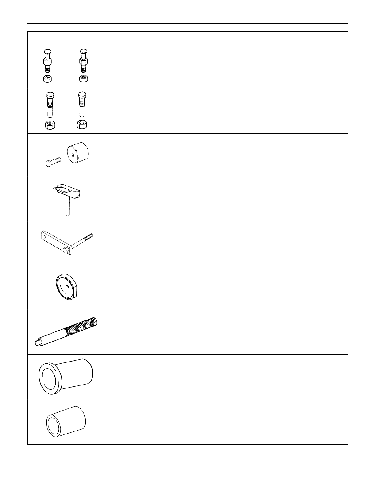
Tool UseNameNumber
ENGINE – Special Tools
11-3
MD998719 Crankshaft pulley
holder pin
MD998715 Pulley holder pin
MD998713 Camshaft oil seal
installer
MD998727 Oil pan remover Removing the oil pan
D Holding the crankshaft pulley
D Holding the camshaft sprocket
Pressfitting the camshaft oil seal
MD998781 Flywheel stopper Securing the flywheel or drive plate
MD998776 Crankshaft rear oil
seal installer
MB990938 Handle
MD998382 Crankshaft front oil
seal installer
Pressfitting the crankshaft rear oil seal
Installing the crankshaft front oil seal
MD998285 Crankshaft front oil
seal guide
11-4
Tool UseNameNumber
ENGINE – Special Tools / Engine Adjustments
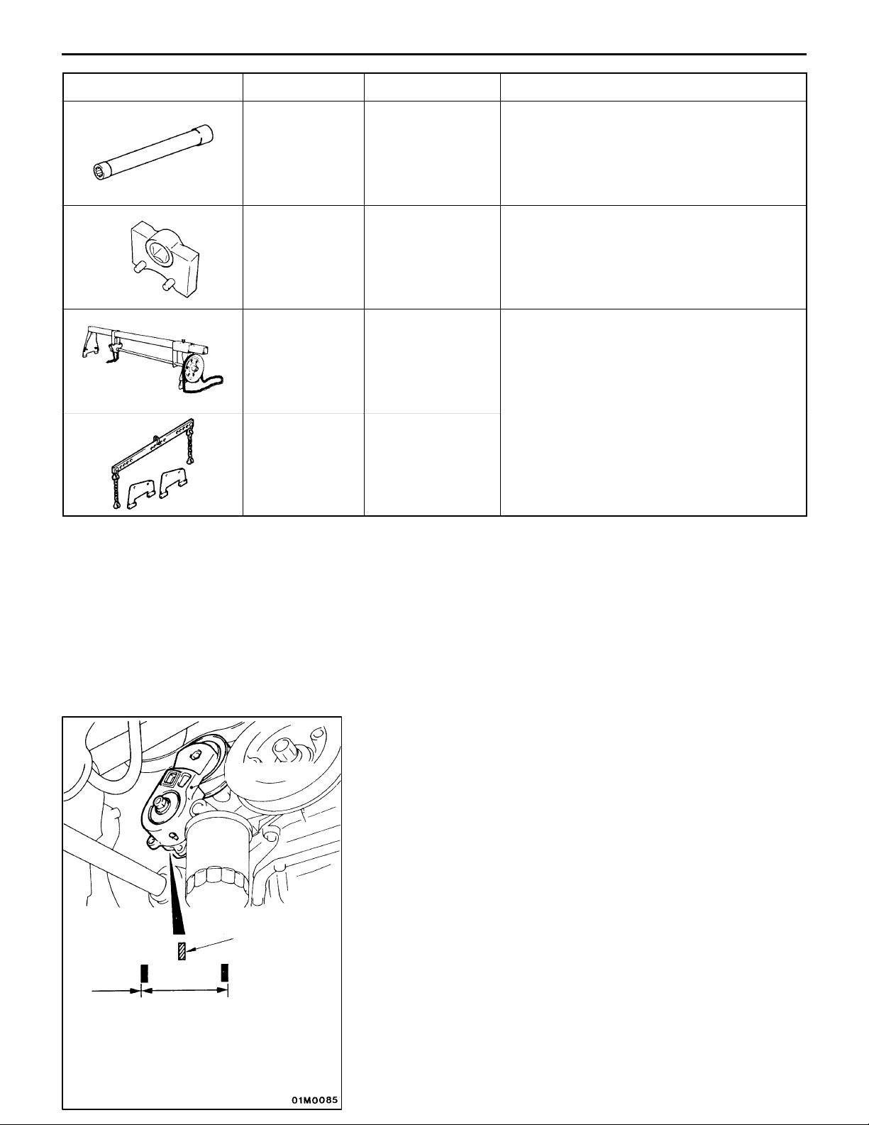
MB991654 Cylinder head bolt
wrench
MD998767 Tensioner pulley
socket wrench
Recommended
tool MZ203826
by Anzen
Jidosha or
MZ203827 by
Banzai
MD991453 Engine hanger
Engine lifter Supporting the engine assembly during
assembly
Removing and reinstalling the cylinder head
bolt
Timing belt tension adjustment
removal and installation of the transmission
ENGINE ADJUSTMENTS
Auto tensioner
Indicator mark
B
A
1. DRIVE BELT TENSION CHECK
NOTE
Use of the auto tensioner eliminates the need for belt tension
adjustment. Check that the indicator mark on the auto
tensioner is in the range of A shown.
If it is outside the specified range (i.e., in range of B shown),
replace the drive belt.
(For the removal and installation of the drive belt, refer to
P.11-9.)

Good
Tool mounting hole
MAX
MIN
High-pressure
chamber
ENGINE – Engine Adjustments
2. AUTO TENSIONER CHECK
(1) Stop the engine from the idle speed and check that the
belt rests within the auto tensioner pulley width.
(2) Remove the drive belt.
(For the removal of the drive belt, refer to P.11-9.)
(3) Fit a spinner handle or similar tool into the tool mounting
hole of the auto tensioner and turn the tensioner clockwise
and counterclockwise to ensure that it does not bind.
(4) If step (1) or (3), or both, have been checked abnormally,
replace the auto tensioner.
(5) Reinstall the drive belt.
3. LASH ADJUSTER CHECK
NOTE
If an unusual knocking noise can be heard immediately after
the engine has started or while it is running and if that is
probably attributable to the lash adjuster, make the following
checks.
(1) Check the engine oil and add or change oil as necessary.
NOTE
(1) If the engine oil level is low, air is taken in through
the oil screen, entering the oil passage.
(2) If the oil level is too high, the cranks agitate oil causing
oil to trap a large amount of air.
(3) Air does not easily separate from a deteriorated oil
that can contain an increased amount of air.
When air trapped in oil for these reasons gets into the
high-pressure chamber of the lash adjuster, the air in
the high-pressure chamber is compressed to shrink the
lash adjuster excessively while the valve is opening,
resulting in an unusual noise occurring. This is the same
symptom developing when the valve clearance is adjusted
to an excessive value.
The problem in this case is gone when air is released
from the lash adjuster.
(2) Start the engine and carry out several cycles (10 or less)
of mild racing*.
If the noise is gone after racing, it indicates that air has
been released from the high-pressure chamber of the
lash adjuster, restoring the lash adjuster to normal
operating conditions.
*: Gradually (extending over a 30-sec. period) increase
the engine speed from idle speed to 3,000 r/min and
then reduce it down to the idle speed gradually
(extending over a 30-sec. period).
11-5
NOTE
(1) If the vehicle is parked on a slope for a long time,
the amount of oil in the lash adjuster will decrease,
causing air to get into the high-pressure chamber
when the engine is started.
(2) After the vehicle has been parked for a long time,
oil drains out of the oil passage and it takes a long
time for the oil to reach the lash adjuster. This can
cause air to get into the high-pressure chamber.

11-6
ENGINE – Engine Adjustments
Timing belt side
AA B B
ABAB
(3) If the noise is not eliminated by racing, follow these steps
to check the lash adjuster.
a. Stop the engine.
b. Bring no. 1 cylinder to TDC on the compression stroke.
c. Push the rocker arms indicated by arrow A on the
left to see if they go down.
d. Slowly turn the crankshaft clockwise 360_.
e. Perform the same step as step c for rocker arms
indicated by arrow B.
f. Push the part of the rocker arm which contacts the
top of the lash adjuster. If the rocker arm can be
easily moved down to the bottom, the lash adjuster
is defective, requiring replacement.
When the lash adjuster is replaced, be sure first to
bleed the lash adjuster of air before installation. Then,
perform steps a through e to ensure that no abnormal
symptoms are noted.
NOTE
(1) The leak-down test is an effective means to
accurately determine if the lash adjuster is
operational or not.
(2) For the leak-down test and bleeding procedures,
refer to ENGINE WORKSHOP MANUAL.
If the rocker arm is felt binding and cannot be
pushed downward as you push it, the lash adjuster
is operational. Check for other possible causes
for the noise.
MD998782
MD998782
(4) Lash adjuster replacement
Caution
From the cylinder from which the lash adjuster is
to be removed, turn the crankshaft to lower the piston,
as the valve contacts the piston when pushed down.
A rocker arm cannot be removed if it is lifted by the
cam. If this is the case, turn the crankshaft so that
the arm is not lifted.
a. Using the special tool, push the valve downward to
remove the roller rocker arm.
b. Remove the lash adjuster from the cylinder head.
c. Mount a brandnew lash adjuster which has been bled
of air in the cylinder head.
d. Using the special tool, lower the valve and install
the roller rocker arm.
NOTE
To mount the roller rocker arm, first place the pivot
side of the rocker arm on the lash adjuster, then push
down the valve; next, place the slipper side of the
rocker arm on the valve system side.

ENGINE – Engine Adjustments
4. LASH ADJUSTER REPLACEMENT
Refer to (4) of the preceding paragraph.
5. IGNITION TIMING CHECK
Check that ignition timing is at the standard value.
Standard value: approx. 5_BTDC
NOTE
Ignition timing is variable within about ±7_, even under normal
operating.
11-7
Crank angle
sensor connector
6. IDLE SPEED CHECK AND IDLE MIXTURE CHECK
(1) Run the engine at 2,000 to 3,000 r/min for 2 minutes.
(2) Check the CO and HC contents at idle.
Standard value
CO contents: 0.6% or less
HC contents: 300 ppm or less
7. COMPRESSION PRESSURE CHECK
(1) Before inspection, check that the engine oil, starter and
battery are normal. In addition, set the vehicle to the
pre-inspection condition.
(2) Remove all of the spark plugs.
(3) Disconnect the crank angle sensor connector.
NOTE
Doing this will prevent the engine-ECU from carrying out
ignition and fuel injection.
(4) Cover the spark plug hole with a shop towel etc., and
after the engine has been cranked, check that no foreign
material is adhering to the shop towel.
Caution
(1) Keep away from the spark plug hole when
cranking.
(2) If compression is measured with water, oil, fuel,
etc., that has come from cracks inside the cylinder,
these materials will become heated and will gush
out from the spark plug hole, which is dangerous.

11-8
Compression gauge
ENGINE – Engine Adjustments
(5) Set compression gauge to one of the spark plug holes.
(6) Crank the engine with the throttle valve fully open and
measure the compression pressure.
Standard value
(at engine speed of 250 r/min): 11.5 kg/cm
Limit (at engine speed of 250 r/min): 9.7 kg/cm
2
2
(7) Measure the compression pressure for all the cylinders,
and check that the pressure differences of the cylinders
are below the limit.
Limit: Max. 1.0 kg/cm
2
(8) If there is a cylinder with compression or a compression
difference that is outside the limit, pour a small amount
of engine oil through the spark plug hole, and repeat
the operations in steps (5) through (7).
a. If the compression increases after oil is added, the
cause of the malfunction is a worn or damaged piston
ring and/or cylinder inner surface.
b. If the compression does not rise after oil is added,
the cause is a burnt or defective valve seat, or pressure
is leaking from the gasket.
(9) Connect the crank angle sensor connector.
(10)Install the spark plugs.
(11)Install the ignition coil and connect the ignition coil
connector.
(12)Erase the diagnosis codes by keeping the battery minus
(–) cable disconnected for more than 10 seconds.
NOTE
This will erase the diagnosis code resulting from the crank
angle sensor connector being disconnected.
Fuel pressure
regulator valve
Vacuum gauge
8. MANIFOLD VACUUM CHECK
(1) Before inspection, set the vehicle to the pre-inspection
condition.
(2) Connect a tachometer connector.
(3) Attach a three-way union to the vacuum hose between
the fuel pressure regulator valve and the intake manifold,
and connect a vacuum gauge.
(4) Start the engine and check that idle speed is within
standard value.
Standard value: 850 ± 50 r/min
5. Check the manifold vacuum at idling.
Limit: Min. 55 kPa {410 mmHg}

ENGINE – Crankshaft Pulley
CRANKSHAFT PULLEY
REMOVAL AND INSTALLATION
11-9
Pre-removal Operation
D Under Cover Removal
1
Post-installation Operation
D Drive Belt Tension Adjustment (Refer to P.11-4.)
D Under Cover Installation
25 {2.5}
2
Removal steps
AA" 1. Drive belt
2. Crankshaft pulley
Auto tensioner
Hole in arm
Hole in bracket
Unit: Nm {kgf@m}
REMOVAL SERVICE POINT
AA" DRIVE BELT REMOVAL
(1) Align the hole in the auto tensioner bracket with that
in the arm and insert a screwdriver into the holes.
(2) Remove the drive belt.
Phillips
screwdriver

11-10
ENGINE – Camshaft and Camshaft Oil Seal
CAMSHAFT AND CAMSHAFT OIL SEAL
REMOVAL AND INSTALLATION
Pre-removal and Post-installation Operation
(1) Engine Coolant Draining and Refilling
(2) Air Hose C Removal and Installation
(Refer to GROUP 15 – Intercooler.)
(3) Spark Plug Cable and Ignition Coil Assembly Removal
and Installation
4
6
2
10 {1.0}
14
15
(4) Air Pipe Removal and Installation
(Refer to GROUP 15 – Air Control Valve.)
(5) Timing Belt Removal and Installation
(Refer to P.11-21.)
9 {0.9}
1
5
3
3.4 {0.35}
20 {2.0}
7
22 {2.2}
8
12 – 15 {1.2 – 1.5}
9
10
Removal steps
1. Breather hose connection
2. PCV hose connection
3. Crank angle sensor bracket connection
4. Control harness connection
5. Rocker cover
6. Radiator upper hose connection
7. Cover
"EA 8. Cam position sensing cylinder
17 16
13
12
88 {9.0}
11
Unit: Nm {kgf@m}
9. Cam position sensor support
10. Semi-circular packing
AA""DA 11. Camshaft sprocket
"CA 12. Camshaft oil seal
"BA 13. Front cam cap
"BA 14. Rear cam cap
"BA 15. Cam cap
"AA 16. Camshaft (exhaust side)
"AA 17. Camshaft (intake side)

ENGINE – Camshaft and Camshaft Oil Seal
Grease and adhesive application points
11-11
26
10 mm
φ 3 mm
Semi-drying sealant:
THREEBOND 1207F
10 mm
Semi-drying sealant: THREEBOND 1207D
Semi-drying sealant: THREEBOND 1207D
10 mm
Timing belt side
Timing belt side
Lip
Engine oil
MB990767
MD998719
Camshaft sprocket side
Camshaft (exhaust side)
Slit
REMOVAL SERVICE POINT
AA" CAMSHAFT SPROCKET REMOVAL
INSTALLATION SERVICE POINTS
"AA CAMSHAFT INSTALLATION
(1) Apply engine oil to the cams and journals of the camshaft.
(2) Mount the camshaft on the cylinder head.
Caution
Make sure that the camshaft has a unique orientation
for installation, the intake side and exhaust side. The
exhaust camshaft has a slit in the rear end face.

11-12
Approx. 12_
Dowel pin
ENGINE – Camshaft and Camshaft Oil Seal
"BA CAM CAP / REAR CAP / FRONT CAM CAP
INSTALLATION
(1) Locate the camshaft dowel pins as illustrated.
Intake side
Exhaust side
(2) Temporarily tighten cam cap in two to three steps, then
torque it to specification.
Tightening torque: 20 Nm {2.0 kgf@m}
"CA CAMSHAFT OIL SEAL INSTALLATION
(1) Apply engine oil to the entire periphery of the oil seal
lip.
(2) Pressfit the oil seal as shown.
ID paint
MD998713
90_
Dowel pin
"DA CAMSHAFT SPROCKET INSTALLATION
As you did during removal, secure the camshaft sprocket
with the special tool and tighten bolt to specification.
Tightening torque: 88 Nm {9.0 kgf@m}
"EA CAM POSITION SENSING CYLINDER
Install the cam position sensing cylinder so that the ID paint
on the cam position sensing cylinder is 90_ with respect to
the camshaft dowel pin as shown.
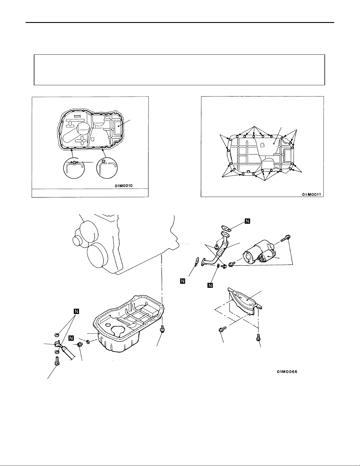
OIL PAN
REMOVAL AND INSTALLATION
Pre-removal and Post-installation Operation
(1) Under Cover Removal and Installation
(2) Front Exhaust Pipe Removal and Installation
(Refer to GROUP 15.)
ENGINE – Oil Pan
(3) Oil Level Gauge Removal and Installation
(4) Engine Oil Draining and Supplying
Identification of bolt location
11-13
8
φ 4 mm
Groove
Semi-drying sealant: THREEBOND 1207D
Bolt
hole
9 {0.9}
3
A
B
A: 6 × 8 mm
B: 6 × 10 mm
B
8
B
B
B
2
1
30 {3.1}
5
8
7
4
39 – 44 {4.0 – 4.5}
"BA 3. Oil return pipe gasket
6
39 {4.0}
Removal steps
1. Starter
2. Oil return pipe
4. Engine oil cooler return pipe
7 {0.7}
26 {2.6}
5. Bell housing cover
6. Drain plug
"AA 7. Drain plug gasket
AA" 8. Oil pan
Washer
assembled bolt
9 {0.9}
Flange bolt
10 {1.0}
Unit: Nm {kgf@m}

11-14
ENGINE – Oil Pan
MD998727
Drain plug gasket
MD998727
Printed portion
Oil pan side
REMOVAL SERVICE POINT
AA" OIL PAN REMOVAL
INSTALLATION SERVICE POINTS
"AA DRAIN PLUG GASKET INSTALLATION
Install the drain plug gasket in the direction so that it faces
as shown in the illustration.
"BA OIL RETURN PIPE GASKET INSTALLATION
Install the gasket with the printed portion toward the oil pan.
Gasket

ENGINE – Crankshaft Oil Seal
CRANKSHAFT OIL SEAL
REMOVAL AND INSTALLATION
11-15
4
127 – 137
{13.0 – 14.0}
5
3
2
1
Crankshaft front oil seal removal
steps
D Timing belt and timing belt B
(Refer to P.11-21.)
D Crank angle sensor
(Refer to GROUP 16.)
1. Crankshaft sprocket B
2. Key
"CA 3. Crankshaft front oil seal
3
Engine oil
Crankshaft rear oil seal removal
steps
D Transmission assembly
D Clutch cover and disc
AA""BA 4. Flywheel
"AA 5. Crankshaft rear oil seal
5
Unit: Nm {kgf@m}

11-16
ENGINE – Crankshaft Oil Seal
REMOVAL SERVICE POINT
AA" FLYWHEEL ASSEMBLY REMOVAL
Use the special tool to secure the flywheel assembly and
remove the bolts.
MD998781
Crankshaft
rear oil seal
MB990938
MB998776
Crankshaft
Oil seal
Crankshaft
INSTALLATION SERVICE POINTS
"AA CRANKSHAFT REAR OIL SEAL INSTALLATION
(1) Apply a small mount of engine oil to the entire
circumference of the oil seal lip.
(2) Install the oil seal with the special tool as far as the
chamfered position of the oil seal case as shown in the
illustration.
"BA FLYWHEEL ASSEMBLY INSTALLATION
Use the special tool to hold the flywheel in the same manner
as removal, and install the bolt. Tighten the bolts to the
specification.
Tightening torque: 127 – 137 Nm {13.0 – 14.0 kgf@m}
"CA CRANKSHAFT FRONT OIL SEAL INSTALLATION
Apply a small amount of engine oil to the entire circumference
of the oil seal lip.
Pressfit the oil seal until it is flush with the chamfered end
of the oil pump case.
MD998382
MD998285
(Lubricate outer
circumference with oil)

ENGINE – Cylinder Head Gasket
CYLINDER HEAD GASKET
REMOVAL AND INSTALLATION
11-17
Pre-removal Operation
(1) Fuel Discharge Prevention
(2) Engine Oil Removal
(3) Strut Tower Bar Removal
(4) Timing Belt Removal (Refer to P.11-21.)
(5) Thermostat Case Assembly Removal
(Refer to GROUP 14 – Water Hose Pipe.)
(6) Front Exhaust Pipe Removal (Refer to GROUP 15.)
Delivery pipe
19
15
18
O-ring
Engine oil
16
18
10
17
8
9
Post-installation Operation
(1) Front Exhaust Pipe Installation
(Refer to GROUP 15.)
(2) Thermostat Case Assembly Installation
(Refer to GROUP 14 – Water Hose Pipe.)
(3) Engine Oil Filling
(4) Timing Belt Installation (Refer to P.11-21.)
(5) Strut Tower Bar Installation
(6) Accelerator Cable Adjustment
10 {1.0}
3 {0.3}
4
1
14
3
2
5 {0.5}
9 {0.9}
6
5
3
8
11
8
7
Removal steps
1. Center cover
2. Accelerator cable connection
3. Ignition coil connector
4. Ignition coil
5. Crank angle sensor connector
6. Crank angle sensor bracket connection
7. Brake booster vacuum hose connection
8. Vacuum hose connection
9. TPS connector
10. ISC motor connector
13
12
12 – 15 {1.2 – 1.5}
20
Unit: Nm {kgf@m}
11. Water hose connection
12. Oxygen sensor connector
13. Injector connector
14. Cam position sensor connector
15. Coolant temperature sensor connector
16. Water temperature gauge unit connector
17. Control harness
"DA 18. Fuel pipe pressure hose connection
19. Fuel return hose connection
20. Oil level gauge guide assembly

11-18
ENGINE – Cylinder Head Gasket
78 → 0 → 20 → +90_ → +90_
{8.0 → 0 → 2.0 → +90_ → +90_}
31
29
23
22
3.4 {0.35}
27
32
33
28
25
24
30
22 {2.2}
21
26
9 {0.9}
10 mm
30 {3.1}
22
10 mm
10 mm
9 {0.9}
Removal steps
21. PCV hose connection
22. Rocker cover
23. Semi-circular packing
24. Starter
25. Oil return pipe
"CA 26. Oil return pipe gasket
27. Vacuum tank/solenoid valve/vacuum
hose assembly
30 {3.1}
10 mm10 mm
23
Semi-drying sealant:
THREEBOND 1207D
28. Intake manifold stay
29. Heater hose connection
30. Alternator brace stay mounting bolt
AA""BA 31. Cylinder head bolt
32. Cylinder head assembly
"AA 33. Cylinder head gasket
22
Unit: Nm {kgf@m}

MB991654
ENGINE – Cylinder Head Gasket
REMOVAL SERVICE POINT
AA" CYLINDER HEAD BOLT REMOVAL
Loosen the bolts in 2 or 3 steps in order of the numbers
shown in the illustration, and remove the cylinder head
assembly.
11-19
Intake side
Exhaust side
Washer
A
Cylinder
head
Front of engine
Cylinder head bolt
(Engine
oil)
INSTALLATION SERVICE POINTS
"AA CYLINDER HEAD GASKET INSTALLATION
(1) Wipe off all oil and grease from the gasket mounting
surface.
(2) Install so that the shapes of the cylinder head holes match
the shapes of the respective cylinder head gasket holes.
"BA CYLINDER HEAD BOLT INSTALLATION
(1) When installing the cylinder head bolts, the length below
the head of the bolts should be within the limit.
If it is outside the limit, replace the bolts.
Limit (A): 99.4 mm
(2) Apply a small amount of engine oil to the thread section
and the washer of the cylinder head bolt.

11-20
MB991654
Intake side
Exhaust side
Front of engine
ENGINE – Cylinder Head Gasket
(3) Tighten the bolts by the following procedure.
Step Operation
1 Tighten to 78 Nm {8.0 kgf@m} in the order shown in the
illustration.
2 Fully loosen in the reverse order of that shown in the
illustration.
3 Tighten to 20 Nm {2.0 kgf@m} in the order shown in the
illustration.
4 Mark the head of the cylinder head bolt and cylinder head
by paint, then tighten 90_ of a turn in the order shown in
the illustration.
5 Tighten 90_ of a turn in the order shown in the illustration.
Check that the painted mark of the head bolt is lined up
with that of the cylinder head.
Caution
(1) Always make a tightening angle just 90_. If it is less
than 90_, the head bolt will be loosened.
(2) If it is more than 90_, remove the head bolt and repeat
the procedure from step 1.
Step 4
90_
Painted mark
Gasket
Step 5
Painted mark
Printed portion
90_
"CA OIL RETURN PIPE GASKET INSTALLATION
Install the gasket with the printed portion toward the oil pan.
"DA HIGH-PRESSURE FUEL HOSE INSTALLATION
(1) Apply a small amount of new engine oil to the O-ring,
then fit the O-ring in the delivery pipe.
Caution
Do not let any engine oil get into the delivery pipe.
(2) Check that the high pressure hose turns smoothly.
If the hose does not turn smoothly, the O-ring is probably
being clamped. Disconnect the high-pressure fuel hose
and check the O-ring for damage. After this, re-install
the hose to the delivery pipe and check that the hose
turns smoothly.
(3) Tighten the mounting bolts to the specification.

TIMING BELT
REMOVAL AND INSTALLATION
ENGINE – Timing Belt
11-21
11 {1.1}
2
9 {0.9}
25
5
1
49 {5.0}
12
118 {12.0}
3
19 {1.9}
6
24 {2.4}
13
45 {4.6}
24 {2.4}
8
11 {1.1}
23
49 {5.0}
18
17
3.5 {0.35}
21
7
22
26
11 {1.1}
27
30 {3.1}
4
15
24
88 {9.0}
48 {4.9}
AA""LA 5. Timing belt
"KA 6. Tensioner pulley
"JA 8. Auto tensioner
AB""IA 11. Oil pump sprocket
AC""HA 12. Crankshaft bolt
AD" 13. Crankshaft sprocket
9
Removal steps
1. Front upper cover
2. Front center cover
3. Front lower cover
4. Bracket
7. Tensioner arm
9. Idle pulley
10. Crankshaft position sensor
14. Sensing blade
54 {5.5}
11
14
16
28
20
19
9 {0.9}
AE""GA 16. Timing belt B
AF""FA 17. Counterbalance shaft sprocket
AG" 19. Crankshaft sprocket B
AH""AA 24. Camshaft sprocket bolt
10
49 {5.0}
15. Tensioner B
"EA 18. Spacer
20. Crankshaft key
"DA 21. Rocker cover
"CA 22. Semi-circular packing
"BA 23. Engine support bracket
25. Camshaft sprocket
26. Timing belt rear right cover
27. Timing belt rear left upper cover
28. Timing belt rear left lower cover
Unit: Nm {kgf@m}

11-22
Timing mark
ENGINE – Timing Belt
REMOVAL SERVICE POINTS
AA" TIMING BELT REMOVAL
(1) If the timing belt is to be reused, chalk an arrow mark
on the back surface of the belt so that the belt can be
reinstalled in the same direction.
(2) Place the exhaust camshaft sprocket in a position where
the timing mark for No. 1 cylinder is positioned about
one tooth before the top dead center of the compression
stroke.
Caution
The camshaft sprocket on the exhaust side can turn
very easily because of the valve spring tension. Use
care not to allow your fingers to get caught by the
sprocket.
(3) Loosen the lock nut of the tensioner pulley, then remove
the timing belt.
AB" OIL PUMP SPROCKET REMOVAL
(1) Remove the plug on the left side of cylinder block.
(2) Insert a screwdriver (shank diameter 8 mm) to block the
counterbalance shaft.
(3) Loosen the flange bolt.
(4) Remove the oil pump sprocket.
AC" CRANKSHAFT BOLT LOOSENING
AD" CRANKSHAFT SPROCKET REMOVAL
If it is difficult to remove the sprocket, use the special tool.

ENGINE – Timing Belt
AE" TIMING BELT “B” REMOVAL
Make an arrow mark on the back of the timing belt indicating
the direction of rotation so it may be reassembled in the
same direction if it is to be reused.
6EN1322
AF" COUNTERBALANCE SHAFT SPROCKET
REMOVAL
11-23
AG" CRANKSHAFT SPROCKET “B” REMOVAL
If it is difficult to remove the sprocket, use the special tool.
AH" CAMSHAFT SPROCKET BOLT LOOSENING
Use a wrench to hold the hexagonal part of the camshaft,
and then remove the camshaft sprocket mounting bolt.
INSPECTION
TIMING BELT
Replace belt if any of the following conditions exist.
(1) Hardening of back rubber.
Back side is glossy without resilience and leaves no indent
when pressed with fingernail.

11-24
ENGINE – Timing Belt
Peeling of
canvas
Cracks on rib root
Cracks
Tooth missing
Cracks
Cracks
on sides
(2) Cracks on rubber back.
(3) Cracks of canvas.
(4) Cracks on rib root.
(5) Cracks on belt sides.
(6) Abnormal wear of belt sides.
NOTE
The sides are normal if they are sharp as if cut by a
knife.
(7) Abnormal wear on teeth.
Initial stage:
Canvas on load side tooth flank worn (Fluffy canvas
fibers, rubber gone and color changed to white, and
unclear canvas texture)
Final stage:
Canvas on load side tooth flank worn down and rubber
exposed (tooth width reduced)
(8) Missing tooth.
12 mm
98 to 196 N {10 to 20 kgf}
Movement
6EN1033
AUTO TENSIONER
(1) Check the auto tensioner for possible leaks and replace
as necessary.
(2) Check the rod end for wear or damage and replace as
necessary.
(3) Measure the rod protrusion. If it is out of specification,
replace the auto tensioner.
Standard value: 12 mm
(4) Press the rod with a force of 98 – 196 N {10 – 20 kgf}
and measure its protrusion. If it is out of specification,
replace the auto tensioner.
Standard value: 1 mm or less

ENGINE – Timing Belt
INSTALLATION SERVICE POINTS
"AA CAMSHAFT SPROCKET BOLT TIGHTENING
Using a wrench, hold the camshaft at its hexagon and tighten
the bolt to the specification.
Caution
Locking the camshaft sprocket with a tool damages the
sprocket.
11-25
Apply sealant
"BA ENGINE SUPPORT BRACKET LEFT
INSTALLATION
Coat the bolts illustrated with sealant before tightening.
Specified sealant: THREEBOND 1207F or equivalent
"CA SEALANT APPLICATION ON SEMI-CIRCULAR
PACKING
Apply sealant to the areas indicated in the illustration.
Specified sealant: THREEBOND 1212D or equivalent
10 mm
Semi-circular
packing
Apply
sealant
10 mm
Cylinder head

11-26
10 mm
ENGINE – Timing Belt
"DA SEALANT APPLICATION ON ROCKER COVER
Apply sealant to the areas indicated in the illustration.
Specified sealant: THREEBOND 1212D or equivalent
10 mm
Apply sealant
10 mm
Apply sealant
Spacer
Chamfer
10 mm
Oil seal
Apply sealant
"EA SPACER INSTALLATION
(1) Apply very thin coat of oil to the outer periphery of the
spacer (oil seal contacting surface).
(2) Install the spacer with the chamfered end toward the
oil seal. Mounting in the reverse direction can damage
the oil seal lip.
"FA COUNTERBALANCE SHAFT SPROCKET
INSTALLATION
Timing
marks
Timing
marks
"GA TIMING BELT “B” INSTALLATION
(1) Align timing marks on the crankshaft sprocket “B” and
counterbalance shaft sprocket with the marks on the front
case respectively.
(2) Install the timing belt “B” on the crankshaft sprocket “B”
and counterbalance shaft sprocket. There should be no
slack on the tension side.

ENGINE – Timing Belt
11-27
Tensioner “B”
Center of
tensioner
pulley
Center
of bolt
T ension side
of timing belt
Timing belt “B”
(3) Make sure that the relationship between the tensioner
pulley center and the bolt center is as shown in the
illustration.
(4) Move the tensioner “B” in the direction of arrow while
lifting with a finger to give a sufficient tension to the tension
side of timing belt. In this condition, tighten bolt to secure
tensioner “B”. When the bolt is tightened, use care to
prevent shaft from turning together. If shaft is turned
together, belt will be overtensioned.
"HA CRANKSHAFT BOLT TIGHTENING
"IA OIL PUMP SPROCKET INSTALLATION
(1) Block the counterbalance shaft in the same way as at
the disassembly to prevent it from turning.
(2) Install the oil pump sprocket.
(3) Apply a proper amount of engine oil to the bearing surfaces
of the flange nuts.
(4) Tighten the flange nuts to the specified torque.
6EN0564
"JA AUTO TENSIONER INSTALLATION
(1) If the auto tensioner rod is in its fully extended position,
reset it as follows.
B
A
a. Clamp the auto-tensioner in the vise with soft jaws.
b. Push in the rod little by little with the vise until the
set hole A in the rod is aligned with the hole B in
the cylinder.
6AE0049

11-28
Holes in
tensioner
pulley
ENGINE – Timing Belt
c. Insert a wire (1.4 mm in diameter) into the set holes.
d. Unclamp the auto tensioner from the vise.
(2) Install the auto tensioner. Leave the wire installed in the
auto tensioner until the timing belt is installed.
6AE0050
"KA TENSIONER PULLEY INSTALLATION
Install the tensioner pulley as shown in the illustration.
6EN1323
Timing marks
Timing marks
"LA TIMING BELT INSTALLATION
(1) Place the exhaust side camshaft sprocket in a position
where its timing mark is one tooth offset from the timing
mark on the rocker cover in the counterclockwise direction.
NOTE
Even if the timing marks on the sprocket and the rocker
cover are brought into alignment, the exhaust camshaft
is forced back by the valve spring tension. It is stabilized
at a position one tooth before the timing mark.
(2) Align the timing mark on the intake side camshaft sprocket
with that on the rocker cover.
NOTE
Even if the timing marks on the sprocket and the cover
are brought into alignment, the intake camshaft is forced
to turn one tooth in the clockwise direction by the valve
spring tension and stabilized there.
(3) Place the timing mark on the crankshaft sprocket one
tooth this side from the mated timing mark as in the case
of the camshaft sprocket.

Timing marks
Plug
Screwdriver
ENGINE – Timing Belt
(4) Align the timing mark on the oil pump sprocket with its
mating mark.
(5) Remove the plug on the left side of the cylinder block
and insert a Phillips screwdriver (shank diameter 8 mm)
through the hole.
If it can be inserted as deep as 60 mm or more, the
timing marks are correctly aligned. If the inserted depth
is only 20 – 25 mm, turn the oil pump sprocket one turn
and realign timing marks. Then check to ensure that the
screwdriver can be inserted 60 mm or more.
(6) Remove the Phillips screwdriver. Place the oil pump
sprocket in a position where its timing mark is one tooth
offset from the mated timing mark in the counterclockwise
direction.
11-29
6EN1327
(7) Fit the timing belt over the exhaust side camshaft sprocket,
and secure it at the illustrated position using a paper
clip.
(8) Turn the intake side camshaft sprocket as shown to a
position where its timing mark is one tooth offset from
the mated timing mark in the counterclockwise direction.
Then, fit the timing belt over the sprocket and secure
it with a paper clip.
NOTE
The intake camshaft will be turned a little clockwise by
the valve spring tension and stabilized in position even
if the belt is clipped at one tooth offset position.
Timing marks
(9) Check to ensure that the timing marks on the intake
camshaft sprocket side are in alignment when the exhaust
camshaft sprocket is turned clockwise to align the timing
marks.
NOTE
The timing belt span between the intake and exhaust
sprockets will have 17 cogs.

11-30
Camshaft
sprocket
Crankshaft
sprocket
ENGINE – Timing Belt
(10)Fit the timing belt over the idler pulley, oil pump sprocket
and crankshaft sprocket in this order.
NOTE
Be careful that the belt does not become slack.
Oil pump
sprocket
(11)Fit the timing belt over the tensioner pulley.
NOTE
When fitting the timing belt over the tensioner pulley,
turn the intake side camshaft sprocket a little
counterclockwise, as this will facilitate the work.
Crankshaft
sprocket
MD998767
(12)Turn the crankshaft pulley a little in the illustrated direction
to pull up the timing belt at the idler pulley side.
(13)Check to ensure that the timing marks on the crankshaft
sprocket, oil pump sprocket and exhaust camshaft
sprocket are all offset one tooth from the corresponding
timing marks in the counterclockwise direction.
(14)Using the special tool, turn the tensioner pulley in the
illustrated direction to strain the timing belt. Then, secure
the tensioner temporarily by tightening the retaining bolt
lightly.
NOTE
There must be no slack in the timing belt between the
intake and exhaust camshafts.
(15)Turn the crankshaft to align the timing mark with the mark
for No. 1 cylinder top dead center in the compression
stroke.
(16)Set the special tool as shown and screw it in up to the
position where the wire inserted in the auto-tensioner
when installing it can be moved lightly.
MD998738

ENGINE – Timing Belt
11-31
MD998767
(17)Loosen the retaining bolt of the tensioner pulley.
Caution
Loosening the retaining bolt can cause the intake
and exhaust camshafts to turn, resulting in slackened
timing belt. Use care that the timing belt does not
come off the sprockets at this time.
(18)Pull up the slack of the timing belt by turning the tensioner
in illustrated direction using the special tool and a torque
wrench (0 – 5 Nm {0 – 0.5 kgf@m}).
(19)From this position, turn back the tensioner until the torque
wrench reading becomes 3.5 Nm {0.36 kgf@m}, then
secure it by tightening the retaining bolt.
(20)Remove the special tool attached in step (16).
(21)Rotate the crankshaft clockwise 2 turns. Then, leave it
intact 15 minutes.
(22)Check to see that the wire inserted when installing the
auto-tensioner can be pulled out lightly. If it can be pulled
out lightly, the timing belt is being tensioned properly.
If so, remove the wire. In addition, check that the rod
protrusion from the auto-tensioner meets the standard
value, which is also an indication of properly tensioned
timing belt.
Standard value: 3.8 – 4.5 mm
(23)If the wire cannot be removed with a light force, repeat
steps (16) through (21) until the proper belt tensioner
is obtained.

ENGINE – Engine Assembly
ENGINE ASSEMBLY
REMOVAL AND INSTALLATION
11-32
Pre-removal Operation
(1) Fuel Discharge Prevention
(2) Hood Removal
(3) Strut Tower Bar Removal
(4) Air Hose C Removal
(Refer to GROUP 15 – Intercooler.)
(5) Radiator Assembly Removal (Refer to GROUP 14.)
(6) Under Cover Removal
(7) Front Exhaust Pipe Removal (Refer to GROUP 15.)
Delivery pipe
17
O-ring
Engine oil
10 – 12
{1.0 – 1.2}
15
14
16
17
13
Post-installation Operation
(1) Front Exhaust Pipe Installation
(Refer to GROUP 15.)
(2) Under Cover Installation
(3) Radiator Assembly Installation
(Refer to GROUP 14.)
(4) Accelerator Cable Adjustment
(5) Air Hose C Installation
(Refer to GROUP 15 – Intercooler.)
(6) Strut Tower Bar Installation
(7) Hood Installation
10 – 12
{1.0 – 1.2}
1
12
5 {0.5}
8
8
9
3 {0.3}
2
18
6
4
5
7
Removal steps
1. Center cover
2. Accelerator cable
3. Brake booster vacuum hose
connection
4. Vacuum hose connection
5. Throttle position sensor connector
6. Idle speed control motor connector
7. Heater hose connection
8. Ignition coil connector
9. Crank angle sensor connector
10. Oxygen sensor connector
11
10
3
Unit: Nm {kgf@m}
11. Injector connector
12. Cam position sensor connector
13. Coolant temperature sensor connector
14. Coolant temperature gauge unit
connector
15. Vacuum pipe/hose assembly
16. Control harness
"CA 17. High-pressure fuel hose connection
18. Fuel return hose connection

11-33
ENGINE – Engine Assembly
39 {4.0}
19
26
27
29
20
9 {0.9}
12 {1.2}
28
57 {5.8}
22
22
21
25
24
23
19. Solenoid valve connector
20. Vacuum tank/solenoid valve/vacuum
hose assembly
21. Oil pressure switch connector
22. Alternator connector
D Drive belt tension inspection
(Refer to P.11-4.)
AA" 23. Drive belt
AB" 24. A/C compressor
AC" 25. Power steering oil pump
D Transmission assembly
98 {10.0}*
Unit: Nm {kgf@m}
26. A/C relay box
27. A/C receiver bracket mounting bolt
28. Oil pressure hose mounting bolt
AC""BA 29. Engine mount bracket
AE""AA 30. Engine assembly
Caution
Mounting locations marked by * should be
provisionally tightened, and then fully tightened after
placing the vehicle horizontally and loading the full
weight of the engine on the vehicle body.

Hole in arm
Phillips
screwdriver
Auto tensioner
Hole in bracket
ENGINE – Engine Assembly
REMOVAL SERVICE POINTS
AA" DRIVE BELT REMOVAL
(1) Align the hole in the auto tensioner bracket with that
in the arm and insert a screwdriver into the holes.
(2) Remove the drive belt.
11-34
MZ203826 or MZ203827
MB991453
AB" POWER STEERING OIL PUMP REMOVAL
Remove the power steering oil pump from the bracket with
the hose attached.
NOTE
Place the removed power steering oil pump in a place where
it will not be a hindrance when removing and installing the
engine assembly, and tie it with a cord.
AC" A/C COMPRESSOR REMOVAL
Disconnect the A/C compressor connector and remove the
compressor from the compressor bracket with the hose still
attached.
NOTE
Place the removed A/C compressor where it will not be a
hindrance when removing and installing the engine assembly,
and tie it with a cord.
AD" ENGINE MOUNT BRACKET REMOVAL
(1) Support the engine with a garage jack.
(2) Remove the special tools which was attached when the
transmission assembly was removed.
(3) Hold the engine assembly with a chain block or similar
tool.
(4) Place a garage jack against the engine oil pan with a
piece of wood in between, jack up the engine so that
the weight of the engine is no longer being applied to
the engine mount bracket, and then remove the engine
mount bracket.

11-35
ENGINE – Engine Assembly
AE" ENGINE ASSEMBLY REMOVAL
After checking that all cables, hoses and harness connectors,
etc., are disconnected from the engine, lift the chain block
slowly to remove the engine assembly upward from the engine
compartment.
INSTALLATION SERVICE POINTS
"AA ENGINE ASSEMBLY INSTALLATION
Install the engine assembly, checking that the cables, hoses,
and harness connectors are not clamped.
MZ203826 or MZ203827
MB991453
"BA ENGINE MOUNT BRACKET INSTALLATION
(1) Place a garage jack against the engine oil pan with a
piece of wood in between, and install the engine mount
bracket while adjusting the position of the engine.
(2) Support the engine with the garage jack.
(3) Remove the chain block and support the engine assembly
with the special tools.
"CA HIGH-PRESSURE FUEL HOSE INSTALLATION
(1) Apply a small amount of new engine oil to the O-ring,
then fit the O-ring in the delivery pipe.
Caution
Do not let any engine oil get into the delivery pipe.
(2) Check that the high pressure hose turns smoothly.
If the hose does not turn smoothly, the O-ring is probably
being clamped. Disconnect the high-pressure fuel hose
and check the O-ring for damage. After this, re-install
the hose to the delivery pipe and check that the hose
turns smoothly.
(3) Tighten the mounting bolt to the specification.

ENGINE
LUBRICATION
CONTENTS
LUBRICANTS 2. . . . . . . . . . . . . . . . . . . . . . . . . . . . . . . . . . . . . . . . . . . . . . .
ENGINE OIL COOLER 2. . . . . . . . . . . . . . . . . . . . . . . . . . . . . . . . . . . . . . .
12-1

12-2
ENGINE LUBRICATION – Lubricants / Engine Oil Cooler
LUBRICANTS
Items Capacity dm3 {ȏ}
Engine oil Quantity in oil filter 0.3 {0.3}
Quantity in oil cooler 0.16 {0.16}
Total quantity 5.1 {5.1}
Brand DIA QUEEN MOTOR OIL (Grade SG or higher); or engine oil in
a can marked with ILSAC certification.
ENGINE OIL COOLER
REMOVAL AND INSTALLATION
Pre-removal and Post-installation Operation
(1) Engine Oil Removal and Refilling
(2) Front Bumper Removal and Installation
(Refer to GROUP 51.)
1
12 {1.2}
Removal steps
1. Engine oil cooler
"AA 2. Feed hose assembly
"AA 3. Return hose assembly
12 {1.2}
29 – 34
{3.0 – 3.5}
2
12 {1.2}
3
39 – 44
{4.0 – 4.5}
39 – 44
{4.0 – 4.5}
Unit: Nm {kgf@m}
INSTALLATION SERVICE POINT
"AA FEED HOSE ASSEMBLY / RETURN HOSE
Fit the hose joint positioning tab into the hole in oil cooler
to secure the hose assembly in position.
TSB Revision
ASSEMBLY INSTALLATION

FUEL
CONTENTS
13-1
MULTIPOINT INJECTION (MPI) 2. . . . . . .
GENERAL INFORMATION 2. . . . . . . . . . . . . . . .
SERVICE SPECIFICATIONS 3. . . . . . . . . . . . . .
SEALANT 3. . . . . . . . . . . . . . . . . . . . . . . . . . . . . . .
SPECIAL TOOLS 4. . . . . . . . . . . . . . . . . . . . . . . .
TROUBLESHOOTING 6. . . . . . . . . . . . . . . . . . . .
ON-VEHICLE SERVICE 30. . . . . . . . . . . . . . . .
1. Idle Position Switch and Throttle Position
Sensor (TPS) Adjustment 30. . . . . . . . . . . . .
2. Fixed SAS Adjustment 30. . . . . . . . . . . . . . . .
3. Basic Idle Speed Adjustment 30. . . . . . . . . .
4. Fuel Pressure Measurement 30. . . . . . . . . . .
5. MPI System Components Layout 31. . . . . .
6. Intake Air Temperature Sensor Check 32. .
7. Engine Coolant Temperature
Sensor Check 32. . . . . . . . . . . . . . . . . . . . . . . .
8. Oxygen Sensor Check 32. . . . . . . . . . . . . . . .
9. Injector Check 34. . . . . . . . . . . . . . . . . . . . . . .
10. Resistor Check 34. . . . . . . . . . . . . . . . . . . . . . .
11. Fuel Pump Relay No.2 Check 35. . . . . . . . .
12. Fuel Pump Resistor Check 35. . . . . . . . . . . .
INJECTOR 36. . . . . . . . . . . . . . . . . . . . . . . . . . . .
THROTTLE BODY 37. . . . . . . . . . . . . . . . . . . . .

13-2
MPI – General Information
MULTIPOINT INJECTION (MPI)
GENERAL INFORMATION
OMPI System Diagram
L1 Oxygen sensor
L2 Air flow sensor
L3 Intake air temperature sensor
L4 Throttle position sensor
L5 Idle switch
L6 Camshaft position sensor
L7 Crank angle sensor
L8 Barometric pressure sensor
L9 High temperature sensor
L10 Engine coolant temperature sensor
L11 Detonation sensor
D Power supply voltage
D Ignition switch-IG
D Ignition switch-ST
D Vehicle speed sensor
D A/C switch
D Power steering fluid pressure switch
D Alternator FR signal
l5 Secondary air
control solenoid
valve
Canister
Check valve
Engine ECU
From
fuel
tank
Throttle position
sensor (with a
built-in
idle
switch)
l1 Injector
l2 ISC servo
l3 Fuel pressure control valve
l4 Waste gate solenoid valve
l5 Secondary air control solenoid valve
D Control relay
D Fuel pump relay
D A/C relay
D Ignition coil
D Exhaust temperature warning lamp
D Engine warning lamp
D Diagnosis output
D Alternator G terminal
D Fan motor relay
D Tachometer
D Fuel pump relay No.2
l2 ISC servo
L4,
L5
Secondary
air valve
L8 Barometric
pressure sensor
L2 Air flow sensor
Air
L3
Intake air temperature sensor
l4 Waste gate
solenoid valve
L1 Oxygen sensor
Waste gate
actuator
To fuel
tank
Fuel
pressure
regulator
From
fuel
pump
L10 Coolant temperature sensor
L7 Crank angle sensor
L1 1 Detonation sensor
Catalytic converter
l3 Fuel pressure
control valve
L6 Camshaft position
sensor
l1 Injector
L9 High temperature
sensor
Given above is the MPI system diagram for EVOLUTION-IV. The MPI system for EVOLUTION-V is different
from this in the following point;
D Oxygen sensor with a heater is adopted.
D The diagnosis connector power supply circuit is different.
D The high temperature sensor is no longer used.

MPI – Service Specifications / Sealant
kPa {kgf/
2
}
SERVICE SPECIFICATIONS
Items Specifications
Basic ignition timing _BTDC 5 ± 3
Basic idle speed rpm 850 ± 50
Throttle position sensor adjusting voltage mV 400 – 1,000
Throttle position sensor resistance kΩ 3.5 – 6.5
ISC servo coil resistance (at 20_C) Ω 28 – 33
Intake air temperature sensor resistance kΩ At 20_C 2.3 – 3.0
At 80_C 0.30 – 0.42
Coolant temperature sensor resistance kΩ At 20_C 2.1 – 2.7
At 80_C 0.26 – 0.36
13-3
Fuel pressure
Injector coil resistance Ω 2 – 3
Amount of injector fuel leak drop/min 1 or less
Oxygen sensor output voltage 0.6 – 1.0
Fuel pressure control valve coil resistance (at 20_C) Ω 28 – 36
f
cm
2
When vacuum hose is connected 230 {2.35}
When vacuum hose is disconnected 289 – 309 {2.95 – 3.15}
SEALANT
Item Specified sealant
Coolant temperature sensor Drying sealant: HELMESEAL H-1M [0110513]
NOTE:
Given in [ ] are MITSUBISHI GENUINE PART numbers.

13-4
MPI – Special Tools
SPECIAL TOOLS
Tool Number Name Use
MB991348 Test harness set D Measurement of voltage during trouble-
shooting
D Inspection using an oscilloscope
MB991519 Alternator harness
connector
MB991536 TPS check
harness
MD998464 Test harness
(4-pin, square)
MD998463 Test harness
(6-pin, square)
Measurement of voltage during
troubleshooting
Adjustment of idle switch and throttle position
sensor (TPS)
Inspection of oxygen sensor
D Inspection of idle speed control servo
D Inspection using an oscilloscope
MD998478 Test harness
(3-pin, triangle)
MD998706 Injector test set Checking the spray condition of injectors
MD998741 Injector test
adaptor
MB991607 Injector test
harness
D Measurement of voltage during trouble-
shooting
D Inspection using an oscilloscope

Tool UseNameNumber
MD998746 Clip Checking the spray condition of injectors
MD998709 Adaptor hose Measurement of fuel pressure
MD998742 Hose adaptor
MB991637 Fuel pressure
MPI – Special Tools
gauge set
13-5
Red harness
White harness
MB991223 Inspection test
herness set
D Pin contact
pressure
inspection
harness
D Market tester
contact probe
(for general
connectors)
MB991529 Diagnostic trouble
code check harness
MB991709 Test harness D Measurement of voltage during trouble-
Measurement of terminal voltage
Reading of diagnosis codes
shooting
D Inspection using an oscilloscope

13-6
Engine warning lamp
(check engine lamp)
MPI – Troubleshooting
TROUBLESHOOTING
1. DIAGNOSIS FUNCTION
1-1 ENGINE WARNING LAMP (CHECK ENGINE LAMP)
If an abnormality occurs in any of the following items related
to the Multipoint Fuel Injection (MPI) system, the engine
warning lamp will illuminate.
If the lamp remains illuminated or if the lamp illuminates while
the engine is running, check the diagnosis code output.
Engine warning lamp inspection items
Engine-ECU
Air flow sensor (AFS)
Intake air temperature sensor
Throttle position sensor (TPS)
Engine coolant temperature sensor
Crank angle sensor
Camshaft position sensor
Barometric pressure sensor
Detonation sensor
Injector
Ignition coil, power transister
Misfire <Evolution-V only>
1-2 METHOD OF READING AND ERASING DIAGNOSIS
CODES
(1) Use the special tool to earth No.1 terminal (diagnosis
control terminal) of the diagnosis connector.
(2) To check ABS system, remove the valve relay.
NOTE
That is because the valve relay is off and the warning
lamp remains illuminated if there is a fault in the ABS
system.
(3) Turn off the ignition switch.
(4) Read out a diagnosis code by observing how the warning
lamp flashes.
Indication of diagnosis code by warning lamp
When the diagnosis code No.24 is output When no diagnosis code is output*
0.5 sec.
1.5 secs. 0.5 sec.
On
Off
Pause
time 3
secs.
Tens signal
Place
division
2 secs.
Units signal
On
Off
A03X0113
0.5 sec. <MPI, A/T>
0.25 sec. <ABS>
NOTE
*: Even if the ABS system is normal, removing the valve relay causes the diagnosis code No.52 to
be output.

MPI – Troubleshooting
13-7
1-3 ERASING DIAGNOSIS CODES
(1) Turn the ignition switch to OFF.
(2) After disconnecting the battery cable from the battery (–) terminal for 10 seconds or more, reconnect
the cable.
(3) After the engine has warmed up, run it at idle for about 15 minutes.
1-4 FAIL-SAFE FUNCTION REFERENCE TABLE
When the main sensor malfunctions are detected by the diagnosis function, the vehicle is controlled
by means of the pre-set control logic to maintain safe conditions for driving.
Malfunctioning item Control contents during malfunction
Air flow sensor (AFS) (1) Uses the throttle position sensor signal and engine speed signal (crank angle sensor
signal) to take reading of the basic injector drive time and basic ignition timing from
the pre-set mapping.
(2) Fixes the ISC servo in the appointed position so idle control is not performed.
Intake air temperature
sensor
Throttle position
sensor (TPS)
Engine coolant
temperature sensor
Camshaft position
sensor
Barometric pressure
sensor
Detonation sensor Switches the ignition timing from ignition timing for super petrol to ignition timing for standard
Ignition coil, power
transistor
Alternator FR terminal Does not control the output of the alternator according to an electrical load. (works as a
Misfire
(Evolution-V only)
Controls as if the intake air temperature is 25_C.
No increase in fuel injection amount during acceleration due to the throttle position sensor
signal.
Controls as if the engine coolant temperature is 80_C.
(This condition is maintained until the ignition switch is turned off even when the sensor signal
returns normal.)
(1) Injects fuel to all cylinders simultaneously for 4 seconds.
(However, after the ignition switch is turned to ON, the No. 1 cylinder top dead centre
is not detected at all.)
(2) Lets the fan motor (radiator and condensor) run at high speed.
Controls as if the barometric pressure is 101 kPa {760 mmHg}.
petrol.
Cuts off the fuel supply to cylinders with an abnormal ignition.
normal alternator)
Cuts off the fuel to the misfiring cylinder if a misfire that could damage the catalyst is detected.

13-8
MPI – Troubleshooting
2. INSPECTION CHART FOR DIAGNOSIS CODES
Code No. Diagnosis item Reference page
12 Air flow sensor (AFS) system 13-8
13 Intake air temperature sensor system 13-9
14 Throttle position sensor (TPS) system 13-9
21 Engine coolant temperature sensor system 13-10
22 Crank angle sensor system 13-11
23 Camshaft position sensor system 13-11
24 Vehicle speed sensor system 13-12
25 Barometric pressure sensor system 13-13
31 Detonation sensor system 13-14
41 Injector system 13-14
44 Ignition coil and power transistor unit system 13-15
64 Alternator FR terminal system 13-16
3. INSPECTION PROCEDURE FOR DIAGNOSIS CODES
Code No. 12 Air flow sensor (AFS) system Probable cause
Range of Check
D Engine speed is 500 r/min or more.
Set conditions
D Sensor output frequency is 3 Hz or less for 4 seconds.
Measure at the air flow sensor connector A-25.
D Connect the connector. (Use
the test harness: MB991709)
1. Voltage between 3 and earth
(Engine: Idling)
OK: 2.2–3.2 V
2. Voltage between 7 and earth
OK: 0–1 V (Engine: idling)
6–9 V (2,000 r/min)
OK
Replace the engine-ECU.
1. NG
Check the air flow sensor circuit.
2. NG
Measure at the engine-ECU con-
nector B-59.
D Connect the connector.
D Voltage between 19 and earth
(Ignition switch: ON)
OK: 6–9 V
Check the following connector:
B-59
Check trouble symptom.
NG
OK
NG
OK
NG
D Malfunction of the air flow sensor
D Improper connector contact, open circuit or
short-circuited harness wire of the air flow sensor
D Malfunction of the engine-ECU
Check the following connector:
A-25
OK
Check trouble symptom.
NG
Repair
Replace the air flow sensor.
NG
Repair
Replace the engine-ECU.

MPI – Troubleshooting
Code No. 13 Intake air temperature sensor system Probable cause
Range of Check
D Ignition switch: ON
D Excluding 60 seconds after the ignition switch is turned to ON or immediately
after the engine starts.
Set conditions
D Sensor output voltage is 4.6 V or more (corresponding to an intake air temperature
of –45_C or less) for 4 seconds.
or
D Sensor output voltage is 0.2V or less (corresponding to an intake air temperature
of 125_C or more) for 4 seconds.
D Malfunction of the intake air temperature sensor
D Improper connector contact, open circuit or
short-circuited harness wire of the intake air
temperature sensor circuit
D Malfunction of the engine-ECU
13-9
Check the intake air temperature sensor. (Refer to P.13-32.)
OK
Measure at the air flow sensor connector A-25.
D Disconnect the connector, and
measure at the harness side.
D Voltage between 6 and earth
(Ignition switch: ON)
OK: 4.5–4.9 V
D Continuity between 5 and earth
OK: Continuity
OK
Check the following connector:
A-25
OK
Check trouble symptom.
NG
NG
NG
NG
Replace air flow sensor.
Check the following connector:
C-62
OK
Check trouble symptom.
NG
Check the harness wire between the
engine-ECU and the intake air temperature sensor connector.
OK
Repair
Replace the engine-ECU.
NG
NG
Repair
Repair
Code No. 14 Throttle position sensor (TPS) system Probable cause
Range of Check
D Ignition switch: ON
D Excluding 60 seconds after the ignition switch is turned to ON or immediately
after the engine starts.
Set conditions
D The sensor output voltage is 0.2 V or less for 4 seconds.
D Malfunction of the throttle position sensor
D Improper connector contact, open circuit or
short-circuited harness wire of the throttle position
sensor circuit
D Improper “ON” state of idle position switch
D Short circuit of the idle position switch signal line
D Malfunction of the engine-ECU
Check the throttle position sensor.
OK
Measure at the throttle position sensor
connector A-16.
D Disconnect the connector, and
measure at the harness side.
D Voltage between 1 and earth
(Ignition switch: ON)
OK: 4.8–5.2 V
D Continuity between 4 and earth
OK: Continuity
OK
Check the throttle position sensor output circuit.
NG
NG
Replace
Check the following connector:
B-62
OK
Check trouble symptom.
NG
Check the harness wire between the
engine-ECU and the throttle position
sensor connector.
OK
Replace the engine-ECU.
NG
NG
Repair
Repair

13-10
MPI – Troubleshooting
Code No. 21 Engine coolant temperature sensor system Probable cause
Range of Check
D Ignition switch: ON
D Excluding 60 seconds after the ignition switch is turned to ON or immediately
after the engine starts.
Set conditions
D Sensor output voltage is 4.6 V or more (corresponding to an engine coolant
temperature of –45_C or less) for 4 seconds.
or
D Sensor output voltage is 0.1 V or less (corresponding to an engine coolant
temperature of 140_C or more) for 4 seconds.
Range of Check
D Ignition switch: ON
D Engine speed is approx. 50 r/min or more
Set conditions
D The sensor output voltage increases from 1.6 V or less (corresponding to an
engine coolant temperature of 40_C or more) to 1.6 V or more (corresponding
to an engine coolant temperature of 40_C or less).
D After this, the sensor output voltage is 1.6 V or more for 5 minutes.
D Malfunction of the engine coolant temperature sensor
D Improper connector contact, open circuit or
short-circuited harness wire of the engine coolant
temperature sensor circuit
D Malfunction of the engine-ECU
Check the engine coolant temperature
sensor. (Refer to P.13-32.)
OK
Measure at the engine coolant temperature sensor connector A-38.
D Disconnect the connector, and
measure at the harness side.
D Voltage between 1 and earth
(Ignition switch: ON)
OK: 4.5–4.9 V
D Continuity between 2 and earth
OK: Continuity
OK
Check the following connector:
A-38
OK
Check trouble symptom.
NG
NG
NG
NG
Replace
Check the following connector:
B-62
OK
Check trouble symptom.
NG
Check the harness wire between the
engine-ECU and the engine coolant
temperature sensor connector.
OK
Repair
Replace the engine-ECU.
NG
NG
Repair
Repair

MPI – Troubleshooting
Code No. 22 Crank angle sensor system Probable cause
Range of Check
D Engine is cranking.
Set conditions
D Sensor output voltage does not change for 4 seconds (no pulse signal input.)
D Malfunction of the crank angle sensor
D Improper connector contact, open circuit or
short-circuited harness wire of the crank angle sensor
D Malfunction of the engine-ECU
13-11
Measure at the crank angle sensor connector A-51.
D Connect the connector. (Use the test harness: MD998478.)
D Voltage between 2 (black clip) and earth (Engine: cranking)
OK: 0.4–4.0 V
D Voltage between 2 (black clip) and earth (Engine: idling)
OK: 1.5–2.5 V
NG
Measure at the crank angle sensor connector A-51.
D Disconnect the connector, and measure at the harness side.
1. Voltage between 3 and earth (Ignition switch: ON)
OK: System voltage
2. Voltage between 2 and earth (Ignition switch: ON)
OK: 4.8–5.2 V
3. Continuity between 1 and earth
OK: Continuity
OK
Check the following connector: A-51
OK
Check trouble symptom.
NG
Replace the crank angle sensor.
NG
Repair
OK
1. NG
2. NG
3. NG
Replace the engine-ECU.
Check the harness wire between the crank angle sensor and the
control relay connector, and repair if necessary.
Check the following connector: B-62
OK
Check trouble symptom.
NG
Check the harness wire
between the engine-ECU and
the crank angle sensor
connector.
OK
Replace the engine-ECU.
Check the harness wire between the crank angle sensor and the
earth, and repair if necessary.
NG
NG
Repair
Repair
Code No. 23 Camshaft position sensor system Probable cause
Range of Check
D Ignition switch: ON
D Engine speed is approx. 50 r/min or more.
Set conditions
D Sensor output voltage does not change for 4 seconds (no pulse signal input.)
Measure at the camshaft position sensor connector A-97.
D Connect the connector.
D Voltage between 2 and earth (Engine: cranking)
OK: 0.4–3.0 V
D Voltage between 2 and earth (Engine: idling)
OK: 0.5–2.0 V
NG
Measure at the camshaft position sensor connector A-97.
D Disconnect the connector, and measure at the harness side.
1. Voltage between 3 and earth (Ignition switch: ON)
OK: System voltage
2. Voltage between 2 and earth (Ignition switch: ON)
OK: 4.8–5.2 V
3. Continuity between 1 and earth
OK: Continuity
OK
Check the following connector: A-97
OK
Check trouble symptom.
NG
Replace the camshaft position sensor.
NG
Repair
OK
1. NG
2. NG
3. NG
D Malfunction of the camshaft position sensor
D Improper connector contact, open circuit or
short-circuited harness wire of the camshaft position
sensor circuit
D Malfunction of the engine-ECU
Replace the engine-ECU.
Check the harness wire between the camshaft position sensor
and the control relay connector, and repair if necessary.
Check the following connector: B-62
OK
Check trouble symptom.
NG
Check the harness wire
between the engine-ECU and
the camshaft position sensor
connector.
OK
Replace the engine-ECU.
NG
NG
Repair
Repair
Check the harness wire between the camshaft position sensor
and the earth, and repair if necessary.

13-12
MPI – Troubleshooting
Code No. 24 Vehicles speed sensor system Probable cause
Range of check
D Ignition switch: ON
D Excluding 60 seconds after the ignition switch is turned to ON or immediately
after the engine starts.
D Idle position switch: OFF
D Engine speed is 3,000 r/min or more.
D Driving under high engine load conditions.
Set conditions
D Sensor output voltage does not change for 4 seconds (no pulse signal input).
D Malfunction of the vehicle speed sensor
D Improper connector contact, open circuit or
short-circuited harness wire of the vehicle speed
sensor circuit
D Malfunction of the engine-ECU
Check the vehicle speed sensor. (Refer to GROUP 54 – Combination Meters.)
OK
Measure at the vehicle speed sensor connector A-19.
D Disconnect the connector, and measure at the harness side.
1. Voltage between 1 and earth (Ignition switch: ON)
OK: System voltage
2. Voltage between 3 and earth (Ignition switch: ON)
OK: 4.8 – 5.2 V
3. Continuity between 2 and earth
OK: Continuity
OK
Check the following
connectors:
A-19, B-62
OK
Check trouble symptom.
NG
Check the harness wire
between the engine-ECU
and the vehicle speed
sensor connector.
OK
Replace the engine-ECU.
NG
NG
Repair
Repair
NG
1. NG
2. NG
3. NG
Replace
Check the following
connectors:
B-64, B-74, B-76
OK
Check trouble symptom.
NG
Check the harness wire
between the vehicle
speed sensor and ignition
switch connector.
OK
Check the ignition switch. (Refer to GROUP 54 – Ignition Switch.)
Check the following
connector:
B-62
OK
Check trouble symptom.
NG
Check the harness wire
between the engine-ECU
and the vehicle speed
sensor connector.
OK
Replace the engine-ECU.
NG
NG
NG
NG
Repair
Repair
Repair
Repair
Check the harness wire between the vehicle speed sensor and
the earth, and repair if necessary.

MPI – Troubleshooting
Code No. 25 Barometric pressure sensor system Probable cause
Range of Check
D Ignition switch: ON
D Excluding 60 seconds after the ignition switch is turned to ON or immediately
after the engine starts.
Set conditions
D Sensor output voltage is 4.5 V or more (corresponding to a barometric pressure
of 114 kPa {855 mmHg} or more) for 4 seconds.
or
D Sensor output voltage is 0.2 V or less (corresponding to a barometric pressure
of 53 kPa {40 mmHg} or less) for 4 seconds.
D Malfunction of the barometric pressure sensor
D Improper connector contact, open circuit or
short-circuited harness wire of the barometric pressure
sensor circuit
D Malfunction of the engine-ECU
13-13
Measure at the air flow sensor connector A-25.
D Connect the connector. (Use
the test harness: MB991709)
D Voltage between 2 and earth
(Ignition switch: ON)
OK: 3.7–4.3 V (Altitude: 0 m)
3.2–3.8 V
(Altitude: 1,200 m)
OK
Measure at the engine-ECU connector B-62.
D Connect the connector.
D Voltage between 85 and earth
(Ignition switch: ON)
OK: 3.7–4.3 V (Altitude: 0 m)
3.2–3.8 V
(Altitude: 1,200 m)
OK
Check the following connectors:
A-25, B-62
OK
NG
NG
NG
Measure at the air flow sensor connector A-25.
D Disconnect the connector , and
measure at the harness side.
D Voltage between 1 and earth
(Ignition switch: ON)
OK: 4.8–5.2 V
D Continuity between 5 and earth
OK: Continuity
OK
Check the following connector:
A-25
OK
Check trouble symptom.
Check the harness wire between
the engine-ECU and the barometric pressure sensor connector, and
repair if necessary.
Repair
NG
NG
NG
Check the following connector:
B-62
OK
Check trouble symptom.
NG
Check the harness wire between
the engine-ECU and the barometric pressure sensor connector.
OK
Repair
Replace the engine-ECU.
Check the harness wire between
the engine-ECU and the barometric pressure sensor connector.
OK
Replace the air flow sensor.
NG
NG
NG
Repair
Repair
Repair
Check trouble symptom.
NG
Replace the engine-ECU.

13-14
MPI – Troubleshooting
Code No.31 Detonation sensor system Probable cause
Range of Check
D Ignition switch: ON
D Excluding 60 seconds after the ignition switch is turned to ON or immediately
after the engine starts.
D Engine speed is approx. 5,000 r/min or more
Set conditions
The change in the detonation sensor output voltage (detonation sensor peak voltage
at each 1/2 revolution of the crankshaft) is less than 0.06 V for 200 times in succession.
D Malfunction of the detonation sensor
D Improper connector contact, open circuit or
short-circuited harness wire of the detonation sensor
circuit
D Malfunction of the engine-ECU
Measure at the detonation sensor connector A-96.
D Disconnect the connector and
measure at the harness side.
D Continuity between 2 and earth
OK: Continuity
NG
Check the harness wire between the
detonation sensor and earth, and repair
if necessary.
OK
Check the following connector:
B-62
OK
Check trouble symptom.
NG
Check the harness wire between the
engine-ECU and the detonation sensor
connector.
NG
Repair
NG
OK
Repair
Replace the detonation sensor.
Check trouble symptom.
Replace the engine-ECU.
Code No. 41 Injector system Probable cause
Range of Check
D Engine speed is approx. 50 –1,000 r/min
D The throttle position sensor output voltage is 1.15 V or less.
Set conditions
D Surge voltage of injector coil is not detected for 4 seconds.
Check the injector. (Refer to P.13-34.)
Check the resistor. (Refer to P.13-34.)
OK
Measure at the resistor connector
A-125.
D Disconnect the connector, and
measure at the harness side.
D Voltage between 3 and earth
(Ignition switch: ON)
OK: System voltage
OK
Measure at the injector connectors
A-53, A-54, A-55, A-56.
D Disconnect the connector, and
measure at the harness side.
D Voltage between 1 and earth
(Ignition switch: ON)
OK: System voltage
OK
Check the injector control circuit.
NG
NG
NG
Replace
Check the harness wire between the
control relay and the resistor connector, and repair if necessary.
Check the following connector:
A-125
Check trouble symptom.
Check the harness wire between the
resistor and the injector connector , and
repair if necessary.
OK
NG
D Malfunction of the injector
D Improper connector contact, open circuit or
short-circuited harness wire of the injector circuit
D Malfunction of the engine-ECU
NG
Repair
NG
MPI – Troubleshooting
Code No. 44 Ignition coil and power transistor unit system Probable cause
Range of Check
D Engine speed is approx. 50 – 4,000 r/min.
D Engine is not being cranked.
Set conditions
D Abnormal engine speed is detected due to misfiring by crank angle sensor. (One
of two coils fails.)
D Malfunction of the ignition coil
D Improper connector contact, open circuit or
short-circuited harness wire of the ignition primary
circuit
D Malfunction of the engine-ECU.
13-15
Check the ignition coil. (Refer to Group 16 – Ignition System.)
OK
Measure at the ignition coil connectors A-110, A-111.
D Disconnect the connector, and measure at the harness.
1. Voltage between 1 and earth (Ignition switch: ON)
OK: System voltage
2. Voltage between 3 and earth (Engine: Cranking)
OK: 0.5 – 4.0 V
3. Continuity between 2 and earth
OK: Continuity
OK
Check the following
connectors:
A-110, A-111
OK
Check trouble symptom.
NG
Check the following items.
D Check the spark plugs and spark plug cables.
D Check the compression pressure.
NG
Repair
NG
1. NG
2. NG
3. NG
Replace
Check the following
connectors:
B-65, B-76
OK
Check trouble symptom.
NG
Check the harness wire between the ignition coil and ignition switch
connector, and repair if necessary.
Check the following
connector:
B-59
OK
Check trouble symptom.
NG
Check the harness wire
between the engine-ECU
and ignition coil connector.
OK
Replace the engine-ECU.
NG
NG
NG
Repair
Repair
Repair
Check the harness wire between the ignition coil connector and
earth, and repair if necessary.

13-16
MPI – Troubleshooting
Code No. 64 Alternator FR Terminal System Probable cause
Range of Check
D Engine speed is approximately 50 r/min or more.
Set conditions
D Input voltage at the alternator FR terminal is 4.5 V or more for 20 seconds.
D Open circuit in alternator FR terminal circuit
D Malfunction of the engine-ECU.
Measure at the alternator connector
D Connect the connector.
(Use test harness MB991519.)
D Voltage between 4 (blue clip)
and earth
(Engine: Idling)
(Radiator fan: Stopped)
(Headlamp: OFF → ON)
(Brake lamp: OFF → ON)
(Rear defogger switch: OFF
→ ON)
OK: Voltage drops by 0.2 to
3.5 V.
OK
Replace the engine-ECU.
NG
Measure at the alternator connector A-05.
D Disconnect the connector , and
measure at the harness side.
D Voltage between 4 and earth
(Ignition switch: ON)
OK: 4.8 – 5.2 V
OK
Check the following connector:
A-05
OK
Check trouble symptom.
NG
Check the harness wire between
the engine-ECU and alternator
connector.
OK
Replace the alternator.
NG
NG
NG
Check the following connectors:
B-60, A-88
OK
Check trouble symptom.
NG
Check the harness wire between
the engine-ECU and alternator
connector.
OK
Repair
Replace the engine-ECU.
Repair
NG
NG
Repair
Repair

MPI – Troubleshooting
13-17
4. PROBLEM SYMPTOMS TABLE
Items Symptom
Starting Won’t start The starter is used to crank the engine, but there is no combustion within the
cylinders, and the engine won’t start.
Fires up and dies There is combustion within the cylinders, but then the engine soon stalls.
Hard starting Engine starts after cranking a while.
Idling
stability
Rough idle
Hunting
Engine speed doesn’t remain constant and changes at idle.
Usually, a judgement can be based upon the movement of the tachometer
pointer, and the vibration transmitted to the steering wheel, shift lever , body , etc.
This is called rough idle or hunting.
Incorrect idle speed The engine doesn’t idle at the usual correct speed.
Engine stall
(Die out)
Engine stall
(Pass out)
The engine stalls when the accelerator pedal is released, regardless of whether
the vehicles is moving or not.
The engine stalls when the accelerator pedal is depressed or while it is being
used.
Driving Hesitation, Sag “Hesitation” is the delay in response of the vehicle speed (engine speed) that
occurs when the accelerator is depressed in order to accelerate from the speed
at which the vehicle is now traveling, or a temporary drop in vehicle speed
(engine speed) during such acceleration. Serious hesitation is called “sag”.
(Refer to Figure 1.)
Poor acceleration Poor acceleration is inability to obtain an acceleration corresponding to the
degree of throttle opening, even though acceleration is smooth, or the inability
to reach maximum speed.
Stumble Engine speed increase is delayed when the accelerator pedal is initially
depressed for acceleration. (Refer to Figure 2.)
Shock The feeling of a comparatively large impact or vibration when the engine is
accelerated or decelerated.
Surge This is repeated forward or rearward surging during constant speed travel or
Knocking A sharp sound like a hammer striking the cylinder walls during driving and which
Stopping Run on
(“Dieseling”)
(Figure 1)
Normal
Vehicle
speed
Initial accelerator pedal
depression
Hesitation
Time
during variable speed travel.
adversely affects driving.
The condition in which the engine continues to run after the ignition switch is
turned to OFF. Also called “Dieseling”.
(Figure 2)
Vehicle
speed
Initial accelerator pedal
depression
Sag
Idling
Normal
Stumble
Time

13-18
Air/fuel mixt
The oxygen sensor signal is used to
(Changes)
*
80
95_C
OFF
iti
g
5. SERVICE DATA LIST
<EVOLUTION-IV>
MPI – Troubleshooting
Item
No.
11 Oxygen
12 Air flow
13 Intake air
Inspection
item
sensor
*
sensor
temperature
sensor
Inspection contents Normal condition
Engine: After having been warmed
up
f
decelerating, and is made richer
when racing.
Engine: After having been warmed
The oxygen sensor signal is used to
check the air/fuel mixture ratio, and
control condition is also checked by
the ECU.
D Engine coolant temperature: _Engine is idling 17 – 43 Hz
D Lamps, electric cooling fan and
all accessories:
D Transmission: Neutral
Ignition switch: ON or with engine
running
ure is made leaner when
up
–
When at 4,000 r/min, engine is
suddenly decelerated
When engine is suddenly
raced
Engine is idling 400 mV or less
2,500 r/min
2,500 r/min 46 – 86 Hz
Engine is raced Frequency increases
When intake air temperature
is –20_C
When intake air temperature
is 0_C
200 mV or less
600 – 1,000 mV
(Changes)
600 – 1,000 mV
in response to racing
–20_C
0_C
When intake air temperature
is 20_C
When intake air temperature
is 40_C
When intake air temperature
is 80_C
14 Throttle
pos
on
sensor
16 Power
supply
voltage
18 Cranking
signal
(ignition
switch-ST)
NOTE
*: When the car is new (distance it travelled is less than 500 km), output frequency of the air flow sensor may
become about 10% higher.
Ignition switch: ON Set to idle position 300 – 1,000 mV
Gradually open Increases in proportion
Open fully 4,500 – 5,500 mV
Ignition switch: ON System voltage
Ignition switch: ON Engine: Stopped OFF
Engine: Cranking ON
20_C
40_C
80_C
to throttle opening
angle

MPI – Troubleshooting
t
tg
(when A/C switch is ON, A/C
13-19
Item
No.
21 Engine
22 Crank angle
Inspection
item
coolant
emperature
sensor
sensor
Inspection contents Normal condition
Ignition switch: ON or with engine
running
D Engine: Idling
D Idle position switch: ON
When engine coolant temperature is –20_C
When engine coolant temperature is 0_C
When engine coolant temperature is 20_C
When engine coolant temperature is 40_C
When engine coolant temperature is 80_C
When engine coolant temperature is –20_C
When engine coolant temperature is 0_C
When engine coolant temperature is 20_C
When engine coolant temperature is 40_C
–20_C
0_C
20_C
40_C
80_C
1,300 – 1,500 rpm
1,300 – 1,500 rpm
1,300 – 1,500 rpm
1,150 – 1,350 rpm
25 Barometric
pressure
sensor
26 Idle position
switch
27 Power
steering fluid
pressure
switch
28 A/C switch Engine: Idling
Ignition switch: ON At altitude of 0 m 101 kPa
Ignition switch: ON
(Check by operating accelerator
pedal repeatedly.)
Engine: Idling Steering wheel stationary OFF
compressor should be operating.)
When engine coolant temperature is 80_C
At altitude of 600 m 95 kPa
At altitude of 1,200 m 88 kPa
At altitude of 1,800 m 81 kPa
Throttle valve: Set to idle
position
Throttle valve: Slightly open OFF*
Steering wheel turning ON
A/C switch: OFF OFF
A/C switch: ON ON
750 – 950 rpm
ON
1

13-20
3
dri
*
3
80
95_C
OFF
D Timing lamp is set. (The timing
motor
D Lamps, electric cooling fan and
D Engine: Idling
MPI – Troubleshooting
Item
No.
41 Injector
44 Ignition
45 ISC
item
drive time*
Injector
ve time
advance
(stepper)
position *
Normal conditionInspection contentsInspection
Engine: Cranking When engine coolant temper-
2
D Engine coolant temperature: _Engine is idling 1.2 – 2.4 ms
*
D Lamps, electric cooling fan and
D Transmission: Neutral
D Engine: After having been
D Engine coolant temperature:
4
D Transmission: Neutral
D Idle position switch: ON
–
all accessories:
warmed up
lamp is set in order to check
actual ignition timing.)
80 – 90_C
f
all accessories: OFF
ature is 0_C (injection is
carried out for all cylinders
simultaneously)
When engine coolant temperature is 20_C
When engine coolant temperature is 80_C
2,500 r/min 1.0 – 2.2 ms
When engine is suddenly
raced
Engine is idling 3 – 13_BTDC
2,500 r/min 24 – 44_BTDC
A/C switch: OFF 2 – 25 steps
A/C switch: OFF → ON Increases by 10 – 70
27 – 41 ms
14 – 22 ms
3.9 – 5.9 ms
Increases
steps
(When A/C switch is ON, A/C
compressor should be operating.)
49 A/C relay Engine: After having been warmed
up/Engine is idling
NOTE
*1: The idle position switch normally turns off when the voltage of the throttle position sensor is 50 – 100 mV
higher than the voltage at the idle position. If the idle position switch turns back on after the throttle valve
is opened, the idle position switch and the throttle position sensor need to be adjusted.
*2: The injector drive time represents the time when the cranking speed is at 250 r/min or below when the power
supply voltage is 11 V.
*3: In a new vehicle [driven approximately 500 km or less], the injector drive time is sometimes 10% longer than
the standard time.
*4: In a new vehicle [driven approximately 500 km or less], the step of the stepper motor is sometimes 30 steps
greater than the standard value.
A/C switch: OFF Increases by 5 – 50
steps
A/C switch: OFF OFF (Compressor
clutch is not operating)
A/C switch: ON ON (Compressor
clutch is operating)

MPI – Troubleshooting
*180
95_C
OFF
3
dri
*
3
80
95_C
OFF
advance
warmed up
<EVOLUTION-V>
Descriptions other than those given below are the same as for the EVOLUTION-IV.
13-21
Item
No.
12 Air flow
41 Injector
44 Ignition
Inspection
item
sensor
drive time*
Injector
ve time
Inspection contents Normal condition
1
*
D Engine coolant temperature: _Engine is idling 12 – 38 Hz
–
D Lamps, electric cooling fan and
all accessories:
D Transmission: Neutral
Engine: Cranking*
2
D Engine coolant temperature: _Engine is idling 0.9 – 2.1 ms
*
D Lamps, electric cooling fan and
D Transmission: Neutral
D Engine: After having been
–
all accessories:
2
2,500 r/min 36 – 76 Hz
Engine is raced Frequency increases
in response to racing
When engine coolant temperature is 0_C
When engine coolant temperature is 20_C
When engine coolant temperature is 80_C
2,500 r/min 0.7 – 1.9 ms
When engine is suddenly
raced
Engine is idling 0 – 13_BTDC
27 – 40 ms
14.5 – 21.7 ms
3.8 – 5.6 ms
Increases
D Timing lamp is set.
NOTE
*1: In a new vehicle (driven approximately 500 km or less), the air flow sensor output frequency is sometimes
10 % higher than the standard frequency.
*2: The injector drive time represents the time when the cranking speed is at 250 r/min or below when the power
supply voltage is 11 V.
*3: In a new vehicle (driven approximately 500 km or less), the injector drive time is sometimes 10 % longer than
the standard time.
2,500 r/min 24 – 44_BTDC

13-22
htly f
f
f
V
l
6. ENGINE-ECU INSPECTION
6-1 TERMINAL VOLTAGES
Engine ECU connector
MPI – Troubleshooting
Terminal
No.
1 No.1 injector While engine is idling after having been warmed up,
14 No.2 injector
2 No.3 injector
15 No.4 injector
3 Fuel pressure control
4 Stepper motor coil (A1) Engine: Immediately after engine has been startedfChanges repeatedly
17 Stepper motor coil (A2)
5 Stepper motor coil (B1)
18 Stepper motor coil (B2)
6 Secondary air control
8 Fuel pump relay Ignition switch: ON Battery voltage
Check item Check condition (Engine condition) Normal condition
Momentarily drops
f
rom 11 – 14 V.
to battery voltage.
valve
solenoid valve
suddenly depress the accelerator pedal. slig
Ignition switch: ON Battery voltage
Engine: Cranking to idling (within about two minutes) 0 – 3 V to battery
voltage
or warming up
Ignition switch: ON Battery voltage
f
rom battery voltage to
0 – 6 V and from 0 – 6
Engine: Idling 0 – 3 V
10 Power transistor unit
(A)
23 Power transistor unit
(B)
11 Wastegate solenoid
valve
12 Power supply Ignition switch: ON Battery voltage
25
19 Air flow sensor reset
signa
20 Fan motor relay (HI) Fan not operating (coolant temperature: 90_C or
Engine speed: 3,000 r/min 0.3 – 3.0 V
Ignition switch: ON Battery voltage
Engine: At idle after having been warmed up (when
premium gasoline is used)
Engine: Idling 0 – 1 V
Engine speed: 3,000 r/min 6 – 9 V
below)
Fan at high speed (coolant temperature: 105_C or
above)
0 – 3 V
Battery voltage
0 – 3 V

MPI – Troubleshooting
(Evoluti
)
13-23
Terminal
No.
21 Fan motor relay (LOW) Fan not operating (coolant temperature: 90_C or
below)
Fan at low speed (coolant temperature: 90 – 100_C) 0 – 3 V
22 A/C relay D Engine: Idling
D A/C switch: OFF to ON (Compressor is being
driven.)
33 Alternator G terminal D Engine: Warm, idle (radiator fan: OFF)
D Headlamp: OFF to ON
D Brake lamp: OFF to ON
D Rear defogger switch: OFF to ON
36 Engine warning lamp Ignition switch: OFF → ON 0 – 3 V → Battery
37 Power steering fluid
pressure switch
Engine: Idling after
warming up
When steering wheel is
stationary
When steering wheel is
turned
Normal conditionCheck condition (Engine condition)Check item
Battery voltage
Battery voltage, or 6 V
or more instantaneously to 0 – 3 V
Voltage rises by 0.2 –
3.5 V.
voltage (After several
seconds have
elapsed)
Battery voltage
0 – 3 V
38 Control relay Ignition switch: OFF Battery voltage
Ignition switch: ON 0 – 3 V
39 Fuel pump relay No.2 While engine is idling, suddenly depress the
accelerator pedal.
40 Exhaust temperature
warning lamp
41 Alternator FR terminal D Engine: Warm, idle (radiator fan: OFF)
45 A/C switch Engine: Idle speed Turn the A/C switch OFF 0 – 3 V
60 Oxygen sensor heater
on-V only
71 Ignition switch-ST Engine: Cranking 8 V or more
Ignition switch: OFF to ON 0 – 3 V to battery
D Headlamp: OFF to ON
D Brake lamp: OFF to ON
D Rear defogger switch: OFF to ON
Turn the A/C switch ON
(A/C compressor is oper-
ating)
Engine: Idling 0 – 3 V
Engine speed: 5,000 r/min Battery voltage
Momentarily rises
slightly from 0 to 3 V.
voltage (After several
seconds have
elapsed)
Voltage drops by 0.2 –
3.5 V.
Battery voltage

13-24
MPI – Troubleshooting
Terminal
No.
72 Intake air temperature
sensor
76 Oxygen sensor Engine: Running at 2,000 r/min after having been
80 Backup power supply Ignition switch: OFF Battery voltage
81 Sensor impressed
voltage
82 Ignition switch-IG Ignition switch: ON Battery voltage
83 Engine coolant
temperature sensor
Ignition switch: ON When intake air tempera-
ture is 0_C
When intake air tempera-
ture is 20_C
When intake air tempera-
ture is 40_C
When intake air tempera-
ture is 80_C
warmed up (Check using a digital type voltmeter)
Ignition switch: ON 4.5 – 5.5 V
Ignition switch: ON When engine coolant
temperature is 0_C
Normal conditionCheck condition (Engine condition)Check item
3.2 – 3.8 V
2.3 – 2.9 V
1.5 – 2.1 V
0.4 – 1.0 V
0 ↔ 0.8 V
(Changes repeatedly)
3.2 – 3.8 V
When engine coolant
temperature is 20_C
When engine coolant
temperature is 40_C
When engine coolant
temperature is 80_C
84 Throttle position sensor Ignition switch: ON Set throttle valve to idle
position
Fully open throttle valve 4.5 – 5.5 V
85 Barometric pressure
sensor
86 Vehicle speed sensor D Ignition switch: ON
87 Idle position switch Ignition switch: ON Set throttle valve to idle
88 Camshaft position
sensor
Ignition switch: ON When altitude is 0 m 3.7 – 4.3 V
When altitude is 1,200 m 3.2 – 3.8 V
D Move the vehicle slowly forward
position
Slightly open throttle
valve
Engine: Cranking 0.4 – 3.0 V
Engine: Idle speed 0.5 – 2.0 V
2.3 – 2.9 V
1.3 – 1.9 V
0.3 – 0.9 V
0.3 – 1.0 V
0 ↔ 5 V
(Changes repeatedly)
0 – 1 V
4 V or more
89 Crank angle sensor Engine: Cranking 0.4 – 4.0 V
Engine: Idle speed 1.5 – 2.5 V
90 Air flow sensor Engine: Idle speed 2.2 – 3.2 V
Engine speed: 2,500 r/min

MPI – Troubleshooting
6-2 RESISTANCE AND CONTINUITY BETWEEN HARNESS SIDE CONNECTORS AND
TERMINALS
Engine-ECU Harness Side Connector Terminal Arrangement
Terminal No. Inspection item Normal condition (Check condition)
1 – 12 No.1 injector 2 – 3 Ω (At 20_C)
14 – 12 No.2 injector
2 – 12 No.3 injector
15 – 12 No.4 injector
3 – 12 Fuel pressure control valve 28 – 36 Ω (At 20_C)
13-25
4 – 12 Stepper motor coil (A1) 28 – 33 Ω (At 20_C)
17 – 12 Stepper motor coil (A2)
5 – 12 Stepper motor coil (B1)
18 – 12 Stepper motor coil (B2)
6 – 12 Secondary air control solenoid valve 28 – 36 Ω (At 20_C)
11 – 12 Wastegate solenoid valve 62 – 74 Ω (At 20_C)
13 – Body earth Engine-ECU earth Continuity established (0 Ω)
26 – Body earth
60 – 12 Oxygen sensor heater (EVOLUTION-V
only)
72 – 92 Intake air temperature sensor 5.3 – 6.7 kΩ (When intake air temperature is 0_C)
74 – 77 High temperature sensor 3 Ω or less
11 – 18 Ω (at 20_C)
2.3 – 3.0 kΩ (When intake air temperature is 20_C)
1.0 – 1.5 kΩ (When intake air temperature is 40_C)
0.30 – 0.42 kΩ (When intake air temperature is 80_C)
83 – 92 Engine coolant temperature sensor 5.1 – 6.5 kΩ (When coolant temperature is 0_C)
2.1 – 2.7 kΩ (When coolant temperature is 20_C)
0.9 – 1.3 kΩ (When coolant temperature is 40_C)
0.26 – 0.36 kΩ (When coolant temperature is 80_C)
87 – 92 Idle position switch Continuity established (when throttle valve is at idle
position)
No continuity (when throttle valve is slightly open)
91 – Body earth – Continuity established

13-26
MPI – Troubleshooting
7. INSPECTION PROCEDURE USING
OSCILLOSCOPE
7-1 AIR FLOW SENSOR (AFS)
Observing waveforms displayed on the oscilloscope allows
you to visually identify possible unusual disturbances in
waveform that could temporarily occur in the air flow sensor
output.
Oscilloscope
Oscilloscope
<Measurement procedure>
(1) Disconnect the air flow sensor connector and connect
the special tool (Test Harness: MB991709) to it. (Ensure
that all terminals are connected.)
(2) Connect the oscilloscope probe to terminal no. 3 of air
flow sensor connector.
NOTE
If the engine ECU connector is used, connect the
oscilloscope probe to terminal no. 90.
(3) Perform the same steps from here on as with the 4G9
engine.
7-2 CAMSHAFT POSITION SENSOR AND CRANK
ANGLE SENSOR
Perform the same steps as with the conventional 4G9 engine
for the inspection.
7-3 INJECTOR
Observing waveforms displayed on the oscilloscope allows
you to visually check the conditions of injector drive signals
actually output from the engine ECU.
Injector Control Signal (Oscilloscope 1)
<Measurement procedure>
(1) Disconnect the injector connector and connect the special
tool (Test Harness: MB991348) to the circuit. (Ensure
that the terminals on both the power supply and engine
ECU sides are connected.)
(2) Connect the oscilloscope probe to terminal no. 2 of injector
connector.
NOTE
If the engine ECU connector is used for the measurement,
take measurements at each of the following terminals.
Connect the oscilloscope probe to terminal no. 1 when
the waveform is observed with no. 1 cylinder, to terminal
no. 14 when the waveform is observed with no. 2 cylinder,
to terminal no. 2 when the waveform is observed with
no. 3 cylinder, and to terminal no. 15 when the waveform
is observed with no. 4 cylinder.

MPI – Troubleshooting
13-27
<Standard waveform>
Point B
Injector
drive time
Point A
Solenoid counter emf
(approx. 7 × 10 V)
Power supply voltage
Observation conditions
Probe selector switch × 10
AC-GND-DC DC
VOLTS/DIV. 1 V
TIME/DIV. 0.5 ms
Misc. –
Engine speed Idle
<Explanation on waveform>
The power supply voltage is being normally applied and, when a signal is received from the engine
ECU, the voltage drops to around 0 V for the period of time equivalent to its drive signal.
When the signal from the engine ECU turns OFF, the counter emf of the coil causes a voltage peak
to develop, thus resuming the power supply voltage.
Injector drive time:
The fuel injection time as determined by the engine ECU according to the output values of sensors
including AFS. Injector drive time = effective injection time + invalid injection time (Invalid injection
time: corrects operation time lag caused by a power supply voltage drop)
Solenoid coil counter emf:
When the signal from the engine ECU turns OFF, counter emf occurs in the injector coil (approx.
65 to 75 V).
Power supply voltage:
The power supply voltage is being applied in the absence of a signal from the engine ECU. If this
voltage is low, it extends the invalid injection time and, thus, the drive time.
<Waveform observation points>
Point A: Strength of solenoid coil counter emf
Solenoid coil counter emf is low or zero. Injector solenoid shorting
Point B: Injector drive time
When the engine is suddenly raced, the drive time temporarily
extends by a wide margin and soon returns to the normal
drive time corresponding to the engine speed.
At idle
During racing

13-28
MPI – Troubleshooting
Injector Power Supply Voltage (Oscilloscope 2)
<Measurement procedure>
(1) Disconnect the resistor connector and connect the special
tool (Harness Connector: MD998463) to the circuit.
(2) Connect the oscilloscope probe to resistor connector
terminal (1) (special tool red clip) when the waveform
is observed with no. 1 cylinder, to terminal (4) (black
clip) when the waveform is observed with no. 2 cylinder,
to terminal (5) (green clip) when the waveform is observed
with no. 3 cylinder, and to terminal (6) (yellow clip) when
the waveform is observed with no. 4 cylinder.
(3) For the power supply voltage, observe the waveform of
the injector control signal at the same time. (Refer to
P.13-26 for the injector control signal measurement
procedure.)
<Standard waveform>
Observation conditions
Injector power supply voltage waveform Injector control signal
Probe selector switch × 1 × 10
AC-GND-DC AC DC
VOLTS/DIV. 5 V 1 V
TIME/DIV. 0.5 ms
Misc. To be timed with injector control signal
Engine speed Idle (850 rpm)
Plunger in fully
opened position
Point B
Injector power supply
voltage waveform
(oscilloscope 2)
Point A
Injector control signal
waveform
(oscilloscope 1)
Fuel injection time
Time

MPI – Troubleshooting
13-29
<Explanation of waveform>
The injector power supply voltage waveform shows a voltage drop caused by resistance of the resistor.
As the amount of current increases, voltage gradually decreases and a spike occurs at the plunger fully
opened position due to counter emf.
<Waveform observation points>
Point A: Voltage drop during fuel injection time (Refer to abnormal waveform example 1.)
Difference from standard waveform Possible cause
Voltage drop during fuel injection time is small (there
should normally be a voltage drop of about 10 V).
Resistance of resistor is too small. Resistance of injector
is too large.
Point B: Spike when plunger is fully open (Refer to abnormal waveform example 2.)
Difference from standard waveform Possible cause
No spike when plunger is fully open Plunger inoperative
<Abnormal waveform examples>
D Example 1
Abnormal waveform
[Cause of problem]
Resistance of the resistor is too small.
[Waveform characteristics]
Normal waveform
Small voltage drop
D Example 2
[Cause of problem]
Plunger is inoperative.
[Waveform characteristics]
No spike when plunger is fully open.
7-4 IGNITION COIL
Perform the same steps as with the conventional 4G9 engine
for the inspection.

13-30
MPI – On-vehicle Service
ON-VEHICLE SERVICE
1. IDLE POSITION SWITCH AND THROTTLE POSITION SENSOR (TPS) ADJUSTMENT
The thickness of the feeler gauge inserted between the fixed
SAS and throttle lever should be 0.45 mm.
2. FIXED SAS ADJUSTMENT
<EVOLUTION-IV>
Turn down one turn after the fixed SAS has touched the
throttle lever.
<EVOLUTION-V>
Turn down 1-1/4 turns after the fixed SAS has touched the
throttle lever.
3. BASIC IDLE SPEED ADJUSTMENT
The basic idle speed should be 850 ± 50 rpm.
4. FUEL PRESSURE MEASUREMENT
The fuel pressure gauge should be installed at the location
shown on the left.

MPI – On-vehicle Service
13-31
5. MPI SYSTEM COMPONENTS LAYOUT
Name Symbol Name Symbol
A/C switch Q Exhaust temperature warning lamp S
A/C relay H Fuel pressure control valve A
Air flow sensor (with a built-in intake air temperature
sensor and barometric pressure sensor)
Camshaft position sensor M ISC servo D
Control relay and fuel pump relay P Oxygen sensor K
Coolant temperature sensor E Power steering fluid pressure switch I
Crank angle sensor J Secondary air control solenoid valve N
Detonation sensor C Throttle position sensor (with a built-in idle switch) D
Diagnosis connector R
Engine ECU O Vehicle speed sensor T
Engine warning lamp S Wastegate solenoid valve G
F Ignition coil and power transistor unit L
Injector B

13-32
MPI – On-vehicle Service
Equipment sideconnector
Air flow sensor
Intake air temperature sensor
6. INTAKE AIR TEMPERATURE SENSOR CHECK
1. Disconnect the air flow sensor connector.
2. Measure resistance between terminals 5 and 6.
Standard value:
2.3 – 3.0 kΩ (at 20_C)
0.30 – 0.42 kΩ (at 80_C)
3. Measure resistance while heating the sensor using a hair
drier.
Normal condition:
Temperature (_C) Resistance (kΩ)
Higher Smaller
4. If the value deviates from the standard value or the
resistance remains unchanged, replace the air flow sensor
assembly.
Engine coolant
temperature sensor
Oxygen sensor equipment side connector
Oxygen sensor connector
Oxygen sensor
7. ENGINE COOLANT TEMPERATURE SENSOR CHECK
The engine coolant temperature sensor is located as shown
on the left.
Standard value:
2.1 – 2.7 kΩ (at 20_C)
0.26 – 0.36 kΩ (at 80_C)
8. OXYGEN SENSOR CHECK
<EVOLUTION-IV>
The sensor connector is located as shown on the left.
<EVOLUTION-V>
(1) Disconnect the oxygen sensor connector and connect
the special tool (Test Harness: MD998464) to the oxygen
sensor connector.

White clip
Blue clip
Red clip
Black clip
MD998464
Red clip
MD998464
Blue clip
MPI – On-vehicle Service
(2) Check that there is continuity (11 to 18 Ω at 20_C) across
terminal no. 1 (special tool red clip) and terminal no. 3
(special tool blue clip) of the oxygen sensor connector.
(3) If there is no continuity, replace the oxygen sensor.
(4) Run the engine until the engine coolant temperature
exceeds 80_C.
(5) Using jumper wires, connect oxygen sensor terminal no.
1 (special tool red clip) and terminal no. 3 (special tool
blue clip) to battery (+) and (–) terminal, respectively.
Caution
Make sure of the correct connections: if a wrong
connection is made, a broken oxygen sensor results.
(6) Connect a digital voltmeter between terminal no. 2 (special
tool black clip) and terminal no. 4 (special tool white clip).
(7) Race the engine repeatedly to measure the oxygen sensor
output voltage.
Standard value:
13-33
Engine Oxygen sensor
output voltage
When
engine is
raced
0.6 – 1.0 V When engine racing is
NOTE
repeated to enrich air-fuel
ratio, an operational oxygen
sensor should output a voltage of 0.6 to 1.0 V.
NOTE
Use the same procedures to remove and install the oxygen
sensor.

13-34
5.5 to 6.5 (at 20_C)
MPI – On-vehicle Service
9. INJECTOR CHECK
Injection Condition Check
(1) Release the residual pressure from the fuel pipe line to
prevent fuel from flowing out.
(2) Remove the injector.
(3) Set up the special tools (Injector Test Set, Adapter, Fuel
Pressure Regulator, and Clip) as illustrated below.
(4) From here on, use the same procedure as with the
conventional 4G9 engine for the check.
Main hose
MB991607
Battery
MD998741
Return hose
Fuel Pressure Regulator: MD1 16395
MD998706
Clip: MD998746
Injector
Resistor
10. RESISTOR CHECK
(1) Disconnect the resistor connector.
(2) Measure resistance across terminals as detailed below.
Standard value
Measurement terminals Resistance (Ω)
1 – 3
4 – 3
_
5 – 3
6 – 3

Fuel pump relay No.2
MPI – On-vehicle Service
11. FUEL PUMP RELAY NO.2 CHECK
(1) Remove fuel pump relay No.2.
(2) Using jumper wires, connect fuel pump relay No.2 terminal
(3) to battery (+) terminal, and terminal (1) to battery
(–) terminal, respectively.
(3) Connecting and disconnecting the jumper wire on the
battery (–) terminal end, check for continuity across
terminal (2) and terminal (5), and across terminal (4) and
terminal (5), of fuel pump relay No.2.
13-35
Jumper wire Continuity across
terminals (2) and (5)
Connected No Yes
Disconnected Yes No
(4) If the continuity is checked abnormally, replace fuel pump
relay No.2.
Continuity across
terminals (4) and (5)
12. FUEL PUMP RESISTOR CHECK
(1) Disconnect the fuel pump resistor connector.
Fuel pump resistor
(2) Measure resistance across the terminals.
Standard value: 0.6 – 0.9 Ω
(3) If the measurement falls outside the specified range,
replace the fuel pump resistor.

13-36
INJECTOR
REMOVAL AND INSTALLATION
MPI – Injector
Pre-removal Operation
(1) Fuel Discharge Prevention
(2) Air Hose D Removal
(Refer to GROUP15 – Intercooler.)
3
4
7
10 – 13 {1.0 – 1.3}
4
Post-installation Operation
(1) Air Hose D Installation
(Refer to GROUP15 – Intercooler.)
(2) Fuel Leakage Check
3, 6
9
1
8
O-ring
8
11
5
12
11
10
6
O-ring
12
2
Removal steps
1. Injector connector
2. PCV hose connection
AA" 3. High-pressure fuel hose connection
4. Fuel return hose connection
5. Vacuum hose connector
AA" 6. Fuel pressure regulator
Engine oil
9 {0.9}
Unit: Nm {kgf@m}
7. Fuel return pipe
AA" 8. Delivery pipe
9. Insulator
10. Insulator
AA""AA 11. Injector
12. Grommet

THROTTLE BODY
REMOVAL AND INSTALLATION
MPI – Throttle Body
13-37
Pre-removal Operation
(1) Engine Coolant Draining
(2) Air Hose D Removal
(Refer to GROUP 15 – Intercooler.)
(3) Strut Tower Bar Removal
19 {1.9}
3
6
Post-installation Operation
(1) Strut Tower Bar Installation
(2) Air Hose D Installation
(Refer to GROUP 15 – Intercooler.)
(3) Engine Coolant Supplying
(4) Accelerator Cable Adjustment
5 {0.5}
2
4
1
7
Removal steps
1. Accelerator cable connection
2. Throttle position sensor connector
3. Idle speed control servo connector
4. Vacuum hose connection
Up
5
Unit: Nm {kgf@m}
5. Water hose connection
6. Throttle body
"AA 7. Throttle body gasket
INSTALLATION SERVICE POINT
"AA THROTTLE BODY GASKET INSTALLATION
Place the gasket so that the projecting part is positioned
as shown in the illustration, and then install it between the
intake manifold and the throttle body.
Towards front
of vehicle

ENGINE
COOLING
CONTENTS
14-1
SERVICE SPECIFICATIONS 2. . . . . . . . . . . . . .
LUBRICANT 2. . . . . . . . . . . . . . . . . . . . . . . . . . . . .
ON-VEHICLE SERVICE 2. . . . . . . . . . . . . . . . . .
Coolant Replacement 2. . . . . . . . . . . . . . . . . . . . . .
THERMOSTAT 3. . . . . . . . . . . . . . . . . . . . . . . . . . .
WATER PUMP 5. . . . . . . . . . . . . . . . . . . . . . . . . . .
WATER HOSE AND WATER PIPE 6. . . . . . . .
RADIATOR 7. . . . . . . . . . . . . . . . . . . . . . . . . . . . . .

14-2
ENGINE COOLING – Service Specifications / Lubricant / On-vehicle Service
SERVICE SPECIFICATIONS
Items Standard value
Thermostat valve opening temperature _C When open 76.5 ± 1.5
When fully open 90
Thermostat lift mm 8.5 or more
LUBRICANT
Items Brand Quantity dm3 {ȏ}
Coolant capacity (in condenser tank) MITSUBISHI GENUINE DIA QUEEN SUPER
LONG LIFE COOLANT
ON-VEHICLE SERVICE
COOLANT REPLACEMENT
CYLINDER BLOCK DRAIN PLUG
44 {4.5}
6 {6}
Drying sealant: HELMESEAL H-1M
RADIATOR CAP VALVE OPENING PRESSURE
CHECK
On EVOLUTION-V, the radiator cap valve opening pressure
must be as shown below.
Standard value: 93 – 123 kPa {0.95 – 1.25 kgf/cm2}
Limit: 83 kPa {0.85 kgf/cm
Unit: Nm {kgf@m}
2
}

ENGINE COOLING – Thermostat
THERMOSTAT
REMOVAL AND INSTALLATION
Pre-removal and Post-installation Operation
D Engine Coolant Draining and Supplying
(Refer to P.14-2.)
D Air Intake Hose Assembly Removal and Installation
(Refer to GROUP 15 – Intercooler.)
14-3
Removal steps
AA""BA 1. Radiator lower hose connection
2. Control wiring harness connection
3. Water inlet fitting
"AA 4. Thermostat
3
5
13 {1.3}
4
1
Unit: Nm {kgf@m}
REMOVAL SERVICE POINT
AA" RADIATOR LOWER HOSE DISCONNECTION
After making mating marks on the radiator hose and the hose
clamp, disconnect the radiator hose.

14-4
ENGINE COOLING – Thermostat
Rubber ring
Jiggle valve
INSTALLATION SERVICE POINTS
"AA THERMOSTAT INSTALLATION
(1) Install the thermostat so that the jiggle valve is facing
straight up.
Caution
Make absolutely sure that no oil is adhering to the
rubber ring of the thermostat. If the rubber ring is
damaged, replace the thermostat.
(2) When assembling the thermostat, be careful not to fold
over or scratch the rubber ring.
"BA RADIATOR LOWER HOSE CONNECTION
(1) Insert each hose as far as the projection of the water
inlet fitting.
(2) Align the mating marks on the radiator hose and hose
clamp, and then connect the radiator hose.
INSPECTION
THERMOSTAT CHECK
(1) Immerse the thermostat in water, and heat the water while
stirring. Check the thermostat valve opening temperature.
V alve lift
Standard value: 76.5 ± 1.5_C
(2) Check that the amount of valve lift is at the standard
value when the water is at the full-opening temperature.
Standard value:
Full-opening temperature: 90_C
Amount of valve lift: 8.5 mm or more
NOTE
Measure the valve height when the thermostat is fully
closed, calculate the valve lift by subtracting this
measurement from the valve height when the thermostat
is fully open.
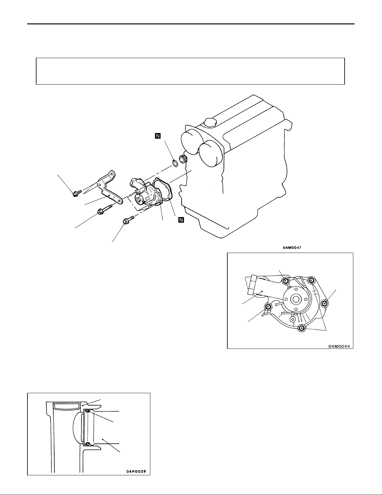
ENGINE COOLING – Water Pump
WATER PUMP
REMOVAL AND INSTALLATION
Pre-removal and Post-installation Operation
D Engine Coolant Draining and Supplying
(Refer to P.14-2.)
22 {2.2}
14-5
D Timing Belt and Timing Belt B Removal and Installation
(Refer to GROUP 11.)
4
1
24 {2.4}
12 – 15 {1.2 – 1.5}
Removal steps
1. Alternator brace
2. Water pump
3. Water pump gasket
"AA 4. O-ring
3
2
Unit: Nm {kgf@m}
Bolt specifications
8 × 70
8 × 14
2
8 × 24
8 × 22
Screw diameter × length mm
Water pump
O-ring
Water inlet pipe
INSTALLATION SERVICE POINT
"AA O-RING INSTALLATION
Fit the O-ring in the O-ring groove in the water inlet pipe,
and coat the outer circumference of the O-ring or the inside
surface of the water pump with water before inserting the
pipe.

14-6
ENGINE COOLING – Water Hose and Water Pipe
WATER HOSE AND WATER PIPE
REMOVAL AND INSTALLATION
Pre-removal and Post-installation Operation
(1) Coolant Draining and Refilling (Refer to P.14-2.)
(2) Air Hose C Removal and Installation
(Refer to GROUP 15 – INTERCOOLER.)
(3) Air Control Valve Bracket Removal and Installation
(Refer to GROUP 15 – AIR CONTROL VALVE.)
3
24 {2.4}
41 {4.2}
10 {1.0}
13 {1.3}
2
48 {4.9}
13
24 {2.4}
8
1
6
7
5
10
4
13 {1.3}
12
11
41 {4.2}
14
10 {1.0}
9
6
Removal steps
AA""CA 1. Radiator upper hose connection
AA""CA 2. Radiator lower hose connection
3. Water hose
4. Water hose
5. Water inlet fitting
"BA 6. Thermostat case assembly
7. Water hose
8. Water hose
Unit: Nm {kgf@m}
"AA 10. O-ring
"AA 12. O-ring
f3mm
Semi-drying sealant:
THREEBOND 1207F
9. Heater hose connection
11. Water inlet pipe
D Turbocharger (Refer to GROUP 15.)
13. Water pipe assembly A
14. Water pipe assembly B

ENGINE COOLING – Radiator
RADIATOR
REMOVAL AND INSTALLATION
Pre-removal and Post-installation Operation
D Engine Coolant Draining and Supplying (Refer to
P.14-2.)
12 {1.2}
14-7
12 {1.2}
2
6
6
3
11
10
13
12
4
6
8
12 {1.2}
5
1
9
9
7
Radiator removal steps
1. Drain plug
2. Radiator cap
3. Overflow hose
4. Reserve tank
5. Reserve tank bracket
AA""AA 6. Radiator upper hose
AA""AA 7. Radiator lower hose
8. Radiator assembly
9. Lower insulator
10. Radiator fan motor assembly
Unit: Nm {kgf@m}
Radiator fan motor removal steps
1. Drain plug
2. Radiator cap
AA""AA 6. Radiator upper hose
D Air intake hose
(Refer to GROUP15 – Intercooler.)
10. Radiator fan motor assembly
11. Fan
12. Radiator fan motor
13. Shroud

14-8
ENGINE COOLING – Radiator
REMOVAL SERVICE POINTS
AA" RADIATOR UPPER HOSE / RADIATOR LOWER
HOSE DISCONNECTION
After making mating marks on the radiator hose and the hose
clamp, disconnect the radiator hose.
INSTALLATION SERVICE POINT
"AA RADIATOR LOWER HOSE / RADIATOR UPPER
HOSE CONNECTION
(1) Insert each hose as far as the projection of the water
inlet or outlet fitting.
(2) Align the mating marks on the radiator hose and hose
clamp, and then connect the radiator hose.
Caution
Fit the clamp on the hose at the same position as
before.
Radiator fan motor relay LO
INSPECTION
1. RADIATOR FAN MOTOR CHECK
Apply the battery voltage across connector terminals 1 and
2, and terminals 3 and 4, of the radiator fan motor and check,
at that time, that the radiator fan turns.
2. POWER RELAY CONTINUITY CHECK
Battery voltage Terminal number
1 3 4 5
When deenergized
When energized

ENGINE COOLING – Radiator
14-9
Radiator fan motor relay HI
Battery voltage Terminal number
1 2 3 4
When deenergized
When energized

INTAKE AND
EXHAUST
CONTENTS
15-1
SERVICE SPECIFICATIONS 2. . . . . . . . . . . . . .
SPECIAL TOOL 2. . . . . . . . . . . . . . . . . . . . . . . . .
ON-VEHICLE SERVICE 2. . . . . . . . . . . . . . . . . .
1. Turbocharger Boost Pressure Check 2. . . .
2. Boost Pressure Control System Check 3. .
3. Wastegate Actuator Check 4. . . . . . . . . . . . .
4. Wastegate Solenoid Valve Check 4. . . . . . .
5. Air Bypass Valve Check 4. . . . . . . . . . . . . . .
6. Secondary Air Control System Check 5. . .
7. Secondary Air Control Solenoid Valve
Check 5. . . . . . . . . . . . . . . . . . . . . . . . . . . . . . . .
8. Secondary Air Valve Check 6. . . . . . . . . . . .
9. Vacuum Tank Check 6. . . . . . . . . . . . . . . . . . .
INTERCOOLER 7. . . . . . . . . . . . . . . . . . . . . . . . . .
AIR CONTROL VALVE 8. . . . . . . . . . . . . . . . . . .
INTAKE MANIFOLD 9. . . . . . . . . . . . . . . . . . . . . .
EXHAUST MANIFOLD AND
TURBOCHARGER 11. . . . . . . . . . . . . . . . . . . . . .
EXHAUST PIPE AND MUFFLER 14. . . . . . . .

15-2
INTAKE AND EXHAUST –
Service Specifications /
Special Tool / On-vehicle Service
SERVICE SPECIFICATIONS
Items Standard value Limit
Turbocharger boost pressure kPa {kg/cm2} 53 – 87 {0.54 – 0.89} –
Wastegate actuator activation pressure kPa {kg/cm2} Approx. 100 {1.02} –
Wastegate solenoid valve coil resistance (at 20_C) Ω 62 – 74 –
Air bypass valve activation pressure kPa {mmHg} Approx. 53 {400} –
Secondary air control solenoid valve coil resistance (at 20_C) Ω 28 – 36 –
Intake manifold and exhaust manifold mounting surface distortion
mm
Within 0.15 0.20
SPECIAL TOOL
Tool Number Name Application
MB998770 Oxygen sensor
wrench
Wastegate
solenoid valve
ON-VEHICLE SERVICE
1. TURBOCHARGER BOOST PRESSURE
Blank plug
CHECK
Removal and installation of oxygen sensor
Caution
Carry out driving tests in a location where full-throttle
acceleration is possible with utmost safety. Two persons
should be in the vehicle during the test, the assistant
in the front passenger seat reading the pressure gauge.
(1) Disconnect the hose (black) from the boost pressure
control solenoid valve and fit the pressure gauge to this
hose.
After the hose (black) has been disconnected, fit a blank
plug to the solenoid valve nipple.
(2) Drive at full-throttle acceleration in second gear and
measure the boost pressure when the engine speed
exceeds about 3,000 r/min.
Standard value:
53 – 87 kPa {0.54 – 0.89 kg/cm
59 – 84 kPa {0.61 – 0.86 kg/cm
2
} <EVOLUTION-IV>
2
} <EVOLUTION-V>

INTAKE AND EXHAUST – On-vehicle Service
(igniti
ON)
(3) If the boost pressure is lower than the standard value,
check for following which are probably the cause:
D Wastegate actuator inoperative
D Boost pressure leak
D Turbocharger defective
(4) If the boost pressure is higher than the standard value,
boost pressure control is probably faulty. Make the
following checks:
D Wastegate actuator inoperative
D Wastegate valve inoperative
D Wastegate actuator rubber hose disconnected or
cracked
15-3
Wastegate
solenoid valve
2. BOOST PRESSURE CONTROL SYSTEM CHECK
(1) Disconnect the hose (black) from the wastegate solenoid
valve and connect a three-way joint between the hose
and solenoid valve.
(2) Connect a hand vacuum pump to the three-way joint.
(3) Disconnect the hose (black) from the intake pipe nipple
connected to the turbocharger compressor housing and
fit a blank plug to this nipple.
(4) Disconnect the negative cable from the battery, keep it
disconnected for 10 sec. or more, and then reconnect
it back again.
(5) Block and unblock the end of the vacuum hose (black)
with a finger to apply vacuum and check for the vacuum
condition.
Engine condition Hose (black) end Normally
Stationary
on switch:
Unblocked Vacuum leaks.
Blocked Vacuum retained.
Idling after warmup Vacuum leaks.
NOTE
If the vacuum condition is faulty, the wastegate actuator,
wastegate solenoid valve, or hose is probably defective.

15-4
INTAKE AND EXHAUST – On-vehicle Service
3. WASTEGATE ACTUATOR CHECK
(1) Connect a hand pump (pressure type) to the nipple.
(2) Gradually increase the pressure being applied to check
for the pressure at which the wastegate actuator rod starts
moving (approx. 1 mm stroke).
Standard value: Approx. 100 kPa {1.02 kg/cm2}
Caution
Do not apply a pressure more than 120 kPa {1.23
kg/cm
damaged.
(3) If the pressure drastically deviates from the standard
value, check the actuator or wastegate valve and, if
necessary, replace the actuator or turbocharger assembly.
2
} to prevent the diaphragm from being
4. WASTEGATE SOLENOID VALVE CHECK
4-1 OPERATION CHECK
(1) Connect a hand vacuum pump to nipple A of the solenoid
valve.
(2) Using jumper wires, connect the solenoid valve terminal
to battery terminals.
(3) Disconnecting and reconnecting the jumper wire on the
(–) terminal side, apply vacuum to check for airtightness.
Jumper wire Nipple B condition Normally
Connected Open Vacuum leaks.
Plugged Vacuum retained.
Disconnected Open Vacuum retained.
4-2 COIL RESISTANCE CHECK
Measure the resistance across solenoid valve terminals.
Standard value: 62 – 74 Ω (at 20_C)
5. AIR BYPASS VALVE CHECK
(1) Remove the air bypass valve.
(2) Connect a hand vacuum pump to the air bypass valve
nipple.
(3) Apply a vacuum of approx. 45 kPa {340 mmHg} and
check that the valve is airtight.
(4) Increase the vacuum and check for valve operation.
Vacuum Valve operation
Approx. 53 kPa {400 mmHg} Starts moving

Secondary air control
solenoid valve
INTAKE AND EXHAUST – On-vehicle Service
6. SECONDARY AIR CONTROL SYSTEM CHECK
(1) Start the engine and let it run at idle speed.
(2) Short-circuit the no. 6 terminal of the engine ECU
connector using a jumper wire and check at this time
that the secondary air valve lifts.
At this time, the engine ECU connector should be
connected.
7. SECONDARY AIR CONTROL SOLENOID VALVE CHECK
7-1 OPERATION CHECK
(1) Disconnect the vacuum hose (white stripe, yellow stripe)
from the solenoid valve.
(2) Disconnect the harness connector.
15-5
Battery
(3) Connect a hand vacuum pump to nipple A of the solenoid
valve.
(4) Using jumper wires, connect the solenoid valve terminal
to battery terminals.
(5) Disconnecting and reconnecting the jumper wire on the
(–) terminal side, apply vacuum to check for airtightness.
Jumper wire Nipple B condition Normally
Connected Open Vacuum leaks.
Plugged Vacuum retained.
Disconnected Open Vacuum leaks.
7-2 COIL RESISTANCE CHECK
Measure the resistance across solenoid valve terminals.
Standard value: 28 – 36 Ω (at 20_C)

15-6
INTAKE AND EXHAUST – On-vehicle Service
8. SECONDARY AIR VALVE CHECK
(1) Remove the secondary air valve.
(2) Connect a hand vacuum pump to the secondary air valve
A
nipple.
(3) Apply a vacuum of 67 kPa {500 mmHg} and check that
the vacuum is retained.
(4) Blow air from side (A) and side (B) of the secondary
air valve to check for air passage.
B
Vacuum Air blowing direction Air passage
0 kPa
(vacuum not applied)
40 kPa {300 mmHg}
or more
(A) → (B) No
(A) → (B) Yes
(B) → (A) No
9. VACUUM TANK CHECK
(1) Connect a hand vacuum pump to nipple A of the vacuum
tank. Applying a vacuum of 67 kPa {500 mmHg}, check
that the vacuum is retained.
A
B
(2) Connect a hand vacuum pump to nipple B of the vacuum
tank.
(3) Apply a vacuum of 67 kPa {500 mmHg] with nipple A
plugged with a finger. Check that the vacuum leaks when
the finger is then released.

INTAKE AND EXHAUST – Intercooler
INTERCOOLER
REMOVAL AND INSTALLATION
Pre-removal and Post-installation Operation
D Front Bumper Removal and Installation
(Refer to GROUP 51.)
Hose clamp
tightening torque
6 {0.6}
15-7
7
6
8
10 – 13
{1.0 – 1.3}
11 10
12
Removal steps
1. Vacuum hose connection
2. Air bypass valve assembly
3. Breather hose connection
4. Vacuum hose connection
5. Air intake hose assembly
"AA 6. Air bypass hose
7. Air hose connection
"AA 8. Air hose D
10 – 13
{1.0 – 1.3}
13
9
14
10 – 13
{1.0 – 1.3}
"AA 9. Air hose C
"AA 10. Air hose A
"AA 12. Air hose B
"AA 14. Air hose B
1
15
16
Unit: Nm {kgf@m}
11. Air pipe A
13. Intercooler assembly
15. Air pipe B
16. Air pipe bracket
2
3
5
10 – 13
{1.0 – 1.3}
4
INSTALLATION SERVICE POINT
"AA AIR HOSE B / AIR HOSE A / AIR HOSE C / AIR
HOSE D / AIR BYPASS HOSE INSTALLATION
Align the alignment mark (white paint) on each hose with
the protrusion on each pipe.

15-8
INTAKE AND EXHAUST – Air Control Valve
AIR CONTROL VALVE
REMOVAL AND INSTALLATION
10 – 12
{1.0 – 1.2}
4 {0.4}
5
4 {0.4}
22 {2.2}
10 – 12 {1.0 – 1.2}
1
2
24 {2.4}
12 – 15 {1.2 – 1.5}
3
4
49 {5.0}
6
24 {2.4}
Removal steps
1. Control harness connection
2. Vacuum pipe hose assembly
3. Air pipe assembly
"AA 4. Gasket
7
22 {2.2}
8
35 {3.6}
Unit: Nm {kgf@m}
5. Air hose
6. Air control valve
7. Engine hanger
8. Air control valve bracket
Protrusion
INSTALLATION SERVICE POINT
"AA GASKET INSTALLATION
Install the gasket so that its protrusion is located as shown.

INTAKE AND EXHAUST – Intake Manifold
INTAKE MANIFOLD
REMOVAL AND INSTALLATION
15-9
Pre-removal Operation
(1) Fuel Discharge Prevention
(2) Throttle Body Removal (Refer to GROUP 13.)
(3) Front Exhaust Pipe Removal (Refer to P.15-14.)
(4) Air Control V alve Bracket Removal (Refer to P.15-8.)
(5) Strut Tower Bar Removal
10 – 13 {1.0 – 1.3}
13
7
14
5
17
15
16
6
7
19
Post-installation Operation
(1) Strut Tower Bar Installation
(2) Air Control Valve Bracket Installation
(Refer to P.15-8.)
(3) Front Exhaust Pipe Installation (Refer to P.15-14.)
(4) Throttle Body Installation (Refer to GROUP 13.)
1
3 {0.3}
2
3
4
10 – 12
{1.0 – 1.2}
12
35 {3.6}
7
10
8
20 {2.0}
9
9 {0.9}
Removal steps
1. Center cover
2. Ignition coil connector connection
3. Oxygen sensor connector connection
4. Crank angle sensor connector connection
5. Injector connector connection
6. PCV hose
7. Vacuum hose connection
8. Brake booster vacuum hose connection
9. Vacuum tank, solenoid valve, and
vacuum hose assembly
35 {3.6}
30 {3.1}
20
20 {2.0}
11
12 – 15 {1.2 – 1.5}
18
22 {2.2}
14
O-ring
Unit: Nm {kgf@m}
10. Intake manifold stay
11. Oil level gauge guide assembly
12. Vacuum hose and pipe mounting
bolt
13. Fuel return hose connection
"AA 14. Fuel high pressure hose connection
AA" 15. Delivery pipe, injector, and pres-
sure regulator assembly
16. Insulator
17. Insulator
18. Alternator brace stay
19. Intake manifold
20. Intake manifold gasket
Engine oil
15

15-10
High-pressure
fuel hose
Delivery pipe
O-ring
INTAKE AND EXHAUST – Intake Manifold
REMOVAL SERVICE POINT
AA" DELIVERY PIPE, INJECTOR AND PRESSURE
REGULATOR REMOVAL
Remove the delivery pipe with the injectors and pressure
regulator attached to it.
Caution
Care must be taken, when removing the delivery pipe,
not to drop the injector.
INSTALLATION SERVICE POINT
"AA HIGH-PRESSURE FUEL HOSE INSTALLATION
(1) When connecting the high-pressure fuel hose to the
delivery pipe, apply a small amount of new engine oil
to the O-ring and then insert the high-pressure fuel hose,
being careful not to damage the O-ring.
Caution
Be careful not to let any engine oil get into the delivery
pipe.
(2) Check to be sure that the high pressure hose turns
smoothly.
If it does not turn smoothly, the O-ring may be trapped.
Remove the high-pressure fuel hose to check for damaged
O-ring and then re-insert it into the delivery pipe and
check once again.
(3) Tighten the mounting bolts to the specification.
INSPECTION
INTAKE MANIFOLD CHECK
(1) Check the intake manifold for damage or cracking and
replace it if defective.
(2) Using a straight edge and feeler gauge, check for distortion
of the cylinder head installation surface.
Standard value: 0.15 mm or less
Limit: 0.2 mm

INTAKE AND EXHAUST – Exhaust Manifold and Turbocharger
EXHAUST MANIFOLD AND TURBOCHARGER
REMOVAL AND INSTALLATION
15-11
Pre-removal and Post-installation Operation
(1) Radiator Removal and Installation
(Refer to GROUP 14.)
(2) Air Intake Hose and Air Hose A Removal and
Installation (Refer to P.15-7.)
(3) Front Exhaust Pipe Removal and Installation
(Refer to P.15-14.)
12 – 15 {1.2 – 1.5}
49 {5.0}
29 {3.0}
1
3
2
49 – 59 {5.0 – 6.0}
17
14
16
13
15
(4) Air Pipe Assembly Removal and Installation
(Refer to P.15-8.)
(5) Engine Oil Removal and Refilling
54 – 64 {5.5 – 6.5}
20
19
49 {5.0}
27 – 32 {2.7 – 3.3}
17 {1.7}
10 – 12 {1.0 – 1.2}
4
6
10 {1.0}
54 – 64 {5.5 – 6.5}
Removal steps
1. Exhaust manifold heat protector
AA" 2. Oxygen sensor
3. Turbocharger heat protector
4. Water pipe assembly A connection
5. Water hose connection
AB" 6. Oil pipe
7. Starter
8. Oil return pipe
"CA 9. Oil return pipe gasket
10. Vacuum hose connection
8
9
9 {0.9}
10
12
11
17 – 20 {1.7 – 2.0}
"BA 12. Air outlet fitting gasket
"AA 15. Turbocharger
42 {4.2}
10
187
30 {3.1}
Unit: Nm {kgf@m}
11. Air outlet fitting
13. Turbocharger gasket
14. Turbocharger assembly
16. Exhaust fitting gasket
17. Exhaust fitting
18. Water pipe hose assembly
19. Exhaust manifold
20. Exhaust manifold gasket
5
10 {1.0}
 Loading...