

Mitsubishi MOTORS Lancer Evolution 2008 Repair Manual
2008
GROUP INDEX
MITSUBISHI
LANCER EVOLUTION
BODY
REPAIR MANUAL
FOREWORD
This manual has been prepared for the use of all
service mechanics engaged in the body repair service.
Body dimensions, welded panel replacement
procedures, body sealing application instructions, and
all the other information required to provide quick and
accurate body repair service are contained herein.
One especially important point is the welding method.
All of the vehicleís original strength and durability can
be maintained by following the welding procedures
contained in this manual.
Now that, in order to maximize the efficiency of the
repair work, first, both the extent of the damage and
the replacement parts that are needed must be
calculated accurately, and then the actual work must
be performed accurately and efficiently.
following also available, and should be used in
The
conjunction with this manual.
TECHNICAL INFORMATION MANUAL
MSSP-260B-2008
SERVICE MANUAL MSSP-206B-2008
PARTS CATALOG BUM6Y108A_
BODY CONSTRUCTION . . . . . . . . .
BODY DIMENSIONS . . . . . . . . . . . . .
WELDED PANEL REPLACEMENT. .
CORROSION PROTECTION . . . . . .
SYNTHETIC-RESIN PARTS . . . . . . .
BODY COLOR . . . . . . . . . . . . . . . . . .
BASE OF BODY REPAIR . . . . . . . . .
1
2
3
4
5
6
9
Mitsubishi Motors Corporation reserves the right to make changes in
design or to make additions to or improvements in its products without
imposing any obligations upon itself to install them on its products
previously manufactured.
©2007 Mitsubishi Motors Corporation
All Rights, Reserved
Printed in USA
MSSP-460B-2008

MANUAL DESCRIPTION
CONTENTS
The first page of this manual contains a table of contents which lists the name of vehicle models and groups
within each model.
TEXT
The vehicles to which the information in the text pertains are generally designated according to their body
classification. In some cases, other limiting designations such as model name, type of drive system, etc., are
given. If there are no such limiting designations, the information can be assumed to cover all models.
PAGE N U M BERS
Al pages are numbered consecutively within each model. The page number can be found on the upper left or
right of each page.
SECTION TITLES
The group titles and section titles can be found at the upper center of each page.
Page number
Group number
Group title
Section title

GROUP 1
BODY
CONSTRUCTION
CONTENTS
1-1
BODY COMPONENTS. . . . . . . . . . . . 1-2
BODY MAIN CROSS-SECTIONAL
VIEWS . . . . . . . . . . . . . . . . . . . . . . . . 1-4
MAINTENANCE, SERVICEABILITY . 1-6
BODY CONSTRUCTION
CHARACTERISTICS . . . . . . . . . . . . . 1-8
FRONT BODY. . . . . . . . . . . . . . . . . . . . . . . 1-8
SIDE BODY. . . . . . . . . . . . . . . . . . . . . . . . . 1-15
REAR BODY . . . . . . . . . . . . . . . . . . . . . . . . 1-17
ROOF . . . . . . . . . . . . . . . . . . . . . . . . . . . . . 1-18
UNDER BODY. . . . . . . . . . . . . . . . . . . . . . . 1-20
DOOR . . . . . . . . . . . . . . . . . . . . . . . . . . . . . 1-24
SILENCER APPLICATION
LOCATIONS . . . . . . . . . . . . . . . . . . . . 1-25
FOAMING MATERIAL USAGE
LOCATIONS . . . . . . . . . . . . . . . . . . . . 1-26
STIFFENER AND DAMP SHEET
APPLICATION LOCATIONS . . . . . . . 1-27
THEFT PROTECTION . . . . . . . . . . . . 1-28
1-2
BODY CONSTRUCTION
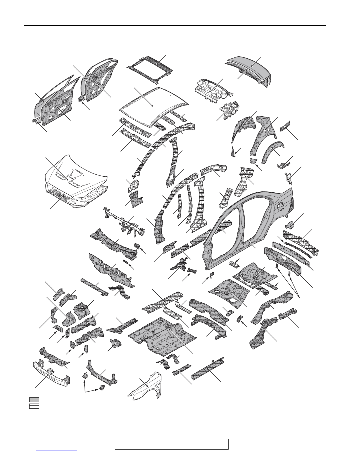
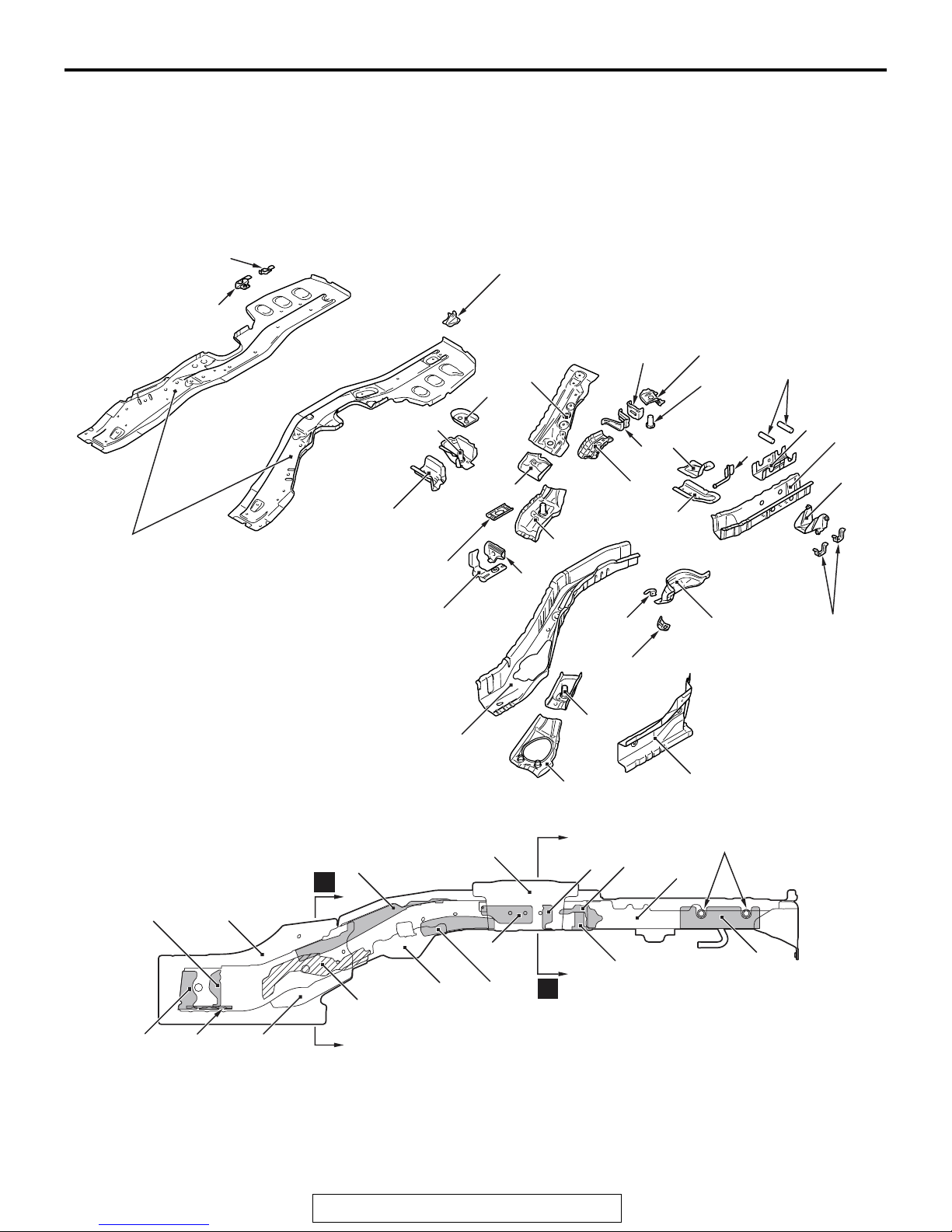
BODY COMPONENTS
27
24
25
30
26
28
BODY COMPONENTS
37
36
29
35
32
31
79
80
33*
*
81
97*
34
99*
*
98
82
92
93
38
39
84
91
83
40
87
86
88
M4010001001309
85
89
90
11
13
12
23
10
9*
14
15
16
8
78
22
18
77
20
21
76
96
95*
94
74**
75**
47
43
70
48
19
*
17
60
73
72
59
71
50
56
54
4*
61*
57*
55
49
51
41
42
44
45
46
52*
58*
5
7
6
2
3
68
66
67
65
62
53
1
: Anti-corrosion steel panels
: High-tensile steel panels (*: Indicates 590MPa-high-tensile steel panels.)
69
(**: Indicates 980MPa-ultra-high-tensile steel panels.)
TSB Revision
64
*
63**
AB700971
AB

BODY CONSTRUCTION
BODY COMPONENTS
1-3
1. Front bumper reinforcement
2. Headlight support panel upper
3. Front body frame to side sill brace
4. Front sidemember rear
5. Front inner sidemember
6. Headlight support panel
7. Front sidemember plate
8. Front outer sidemember
9. Front sidemember extension
10. Front fender gusset
11. Headlight support panel upper
12. Front fender shield
13. Fender shield frame upper outer
14. Fender shield frame upper inner
15. Spring house panel
16. Dash panel crossmember upper
17. Dash panel crossmember lower
18. Dash panel
19. Brake pedal support reinforcement
20. Cowl top panel
21. Brake pedal support bracket
22. Front deck crossmember
23. Hood panel inner
24. Hood panel outer
25. Front door side door beam
26. Front door panel inner
27. Front door panel outer
28. Rear door side door beam
29. Rear door panel inner
30. Rear door panel outer
31. Roof rail front lower
32. Roof rail front upper
33. Roof bow center lower <Vehicles without sunroof
(aluminum panel)>
34. Roof bow center upper <Vehicles without sunroof
(aluminum panel)>
35. Roof rail rear
36. Roof panel
37. Roof panel reinforcement <Vehicles with sunroof
(steel panel)>
38. Rear shelf panel
39. Trunk lid panel inner
40. Trunk lid panel outer
41. Fuel filler door panel (Left side)
42. Rear bumper reinforcement
43. Rear bumper reinforcement
44. Rear end panel outer
45. Rear end panel inner
46. Rear bumper side bracket
47. Rear seatback bracket lower
48. Rear floor
49. Rear floor rear end crossmember
50. Rear floor crossmember
51. Rear floor side panel
52. Rear floor sidemember extension
53. Rear floor sidemember lower
54. Rear seat under floor
55. Rear seat belt reinforcement (Left side)
56. Rear seat belt reinforcement (Right side)
57. Rear floor extension
58. Rear floor rear seat under crossmember
59. Front floor crossmember rear
60. Front floor backbone reinforcement
61. Front floor crossmember front
62. Front floor
63. Front floor side sill inner
64. Front floor sidemember
65. Front floor crossmember rear center
66. Front floor crossmember front
67. Front fender
68. Headlight support panel lower
69. Radiator bracket lower
70. Side outer panel
71. Front fender bracket
72. Upper frame to front pillar brace
73. Front deck frame upper outer
74. Side sill reinforcement outer front
75. Side sill reinforcement outer rear
76. Side sill inner support front
77. Front pillar lower reinforcement
78. Front pillar inner lower
79. Front pillar inner center
80. Front upper inner pillar
81. Roof side rail inner
82. Rear seatback brace
83. Rear wheel house panel inner
84. Rear wheel house panel front lower outer
85. Quarter panel lower inner (Left side)
86. Quarter panel inner
87. Quarter panel extension inner
88. Quarter panel extension lower outer
89. Quarter panel extension outer
90. Rear combination light housing panel
91. Rear pillar reinforcement
92. Roof side rail reinforcement rear
93. Rear pillar reinforcement lower
94. Center pillar reinforcement
95. Rear door hinge reinforcement
96. Rear door hinge reinforcement support
97. Roof side rail reinforcement
98. Center pillar inner lower
99. Center pillar inner upper
TSB Revision
1-4
BODY CONSTRUCTION
BODY MAIN CROSS-SECTIONAL VIEWS
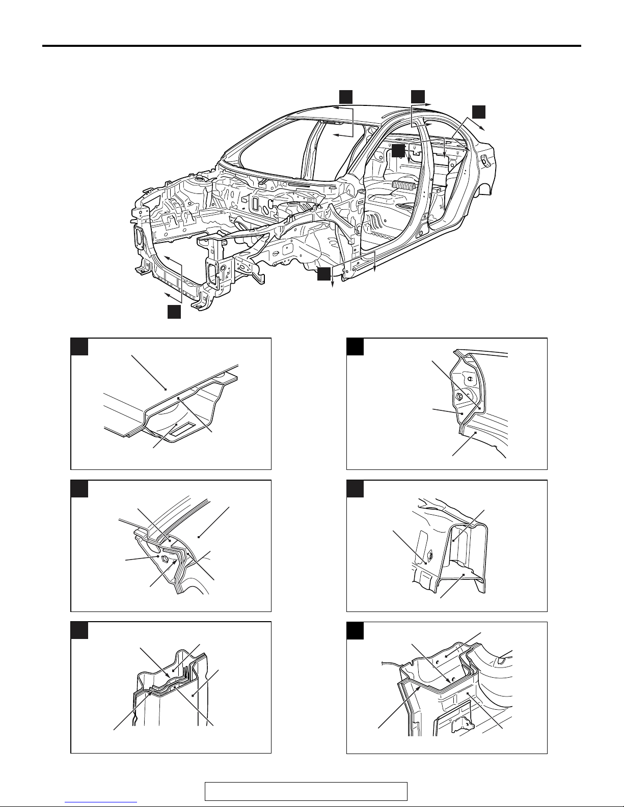
BODY MAIN CROSS-SECTIONAL VIEWS
M4010002001067
A
F
E
A
Roof panel
Roof side rail
D
reinforcement rear
B
D
C
AB700285
AB
B
Roof side
rail inner
Rear door hinge
C
reinforcement
support
Roof rail
front lower
Roof side rail
reinforcement
front
Roof side
rail support
Roof rail
front upper
AB601100
Side outer
panel
Center pillar
reinforcement
AB700969
Center pillar
inner upper
Side outer
panel
AC
AB
Roof side
rail inner
E
Front end
crossmember
upper
Front end
crossmember lower
Front door hinge
F
reinforcement lower
Side outer panel
AB700536
Front end
crossmember
bulkhead
AB601099
Front pillar
inner lower
AB
AC
Rear door hinge
reinforcement
Center pillar
reinforcement
AB601102
AC
TSB Revision
Front pillar
reinforcement lower
Side outer
panel
AB700537
AB
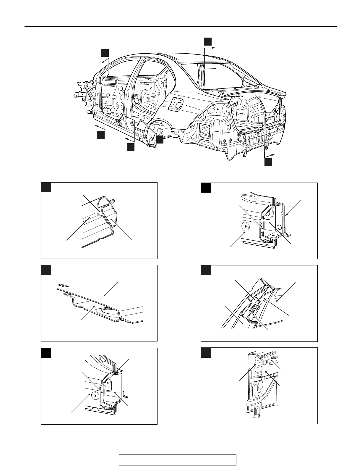
BODY CONSTRUCTION
BODY MAIN CROSS-SECTIONAL VIEWS
H
G
1-5
G
Side outer
panel
H
Roof side rail
reinforcement
front
Roof rail rear
I
Roof panel
J
Front upper
inner pillar
AB602354
AB601108
AC
AB
K
L
J
Side sill
AB700286
Rear floor
side sill
inner
AB
reinforcement
outer rear
Front floor
side sill
Side outer panel
Rear pillar
K
reinforcement
lower
inner
AB700539
AB
Rear wheel
house panel
inner
Side outer
panel
Quarter
inner
panel
Quarter panel extension
lower outer
AB700540
AB
I
Side sill
reinforcement
outer front
Side outer
panel
Front pillar
inner lower
Side sill inner
support front
AB700538
AB
TSB Revision
L
Rear end
panel inner
Rear bumper
reinforcement
Rear end
panel outer
AB601110
AC

1-6
BODY CONSTRUCTION
MAINTENANCE, SERVICEABILITY
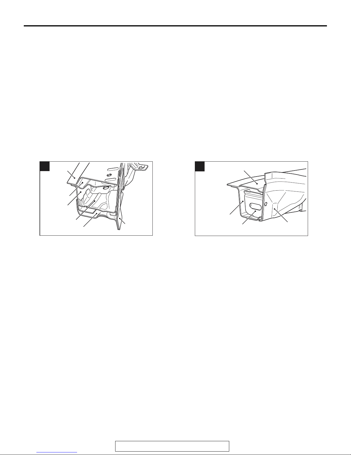
MAINTENANCE, SERVICEABILITY
FENDER SHIELD
A positioning hole, lug, and notch have been added
on the front end upper bar side, front upper frame
inner, upper frame extension inner, front side mem
ber brace upper and dash panel to improve assembling workability during panel replacement.
-
M4010003000948
TSB Revision
AB700964
AB
BODY CONSTRUCTION
MAINTENANCE, SERVICEABILITY
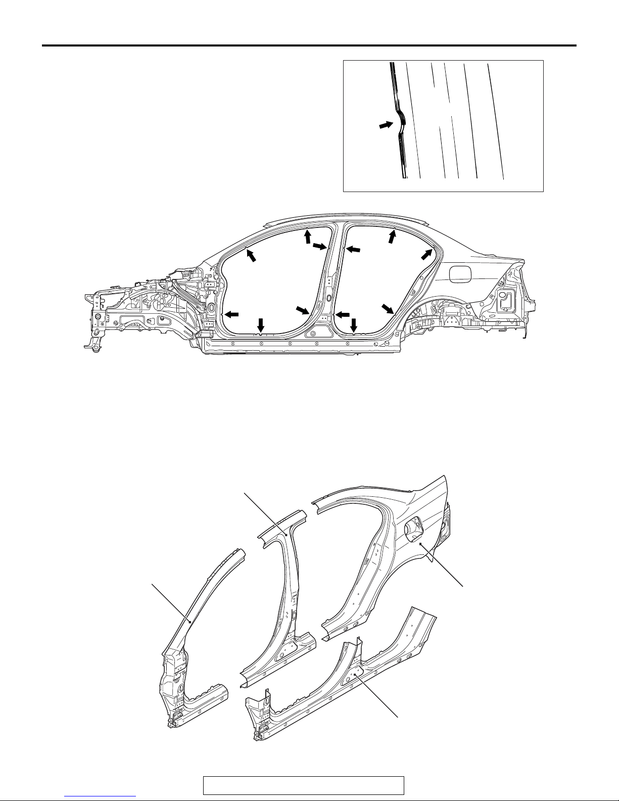
SIDE STRUCTURE
A panel positioning notch has been added on the
door opening to improve assembling workability
when replacing the panel.
1-7
SIDE OUTER PANEL
The extra parts are supplied in 4 different cut forms
as a result of employing the integrated side-frame
side outer panel.
Panel positioning notch
AB201388
AB700289
AB
AB
Front outer pillar
Center outer pillar
Quarter panel outer
Front floor side sill outer
AB700613
AB
TSB Revision
1-8
BODY CONSTRUCTION
BODY CONSTRUCTION CHARACTERISTICS
BODY CONSTRUCTION CHARACTERISTICS
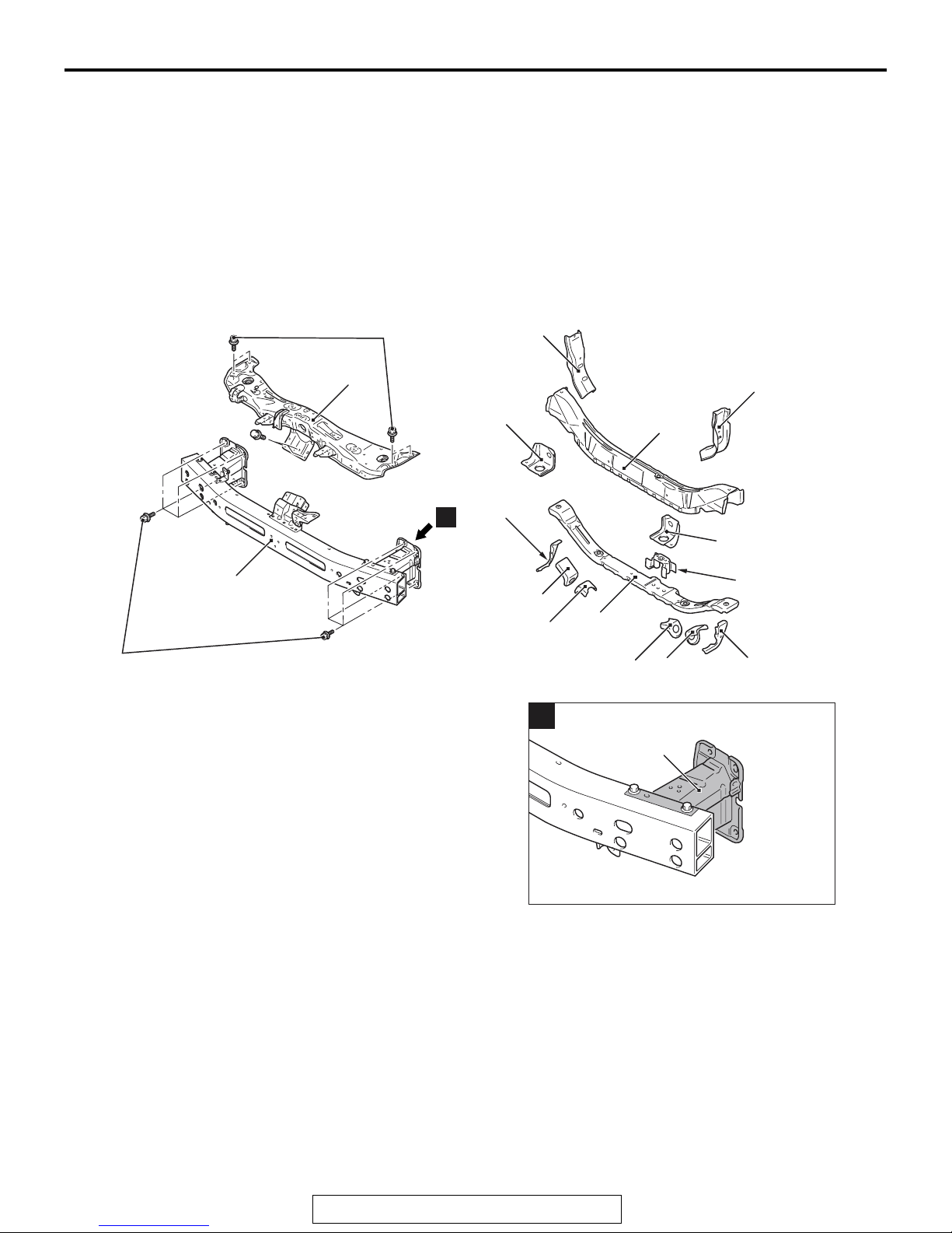
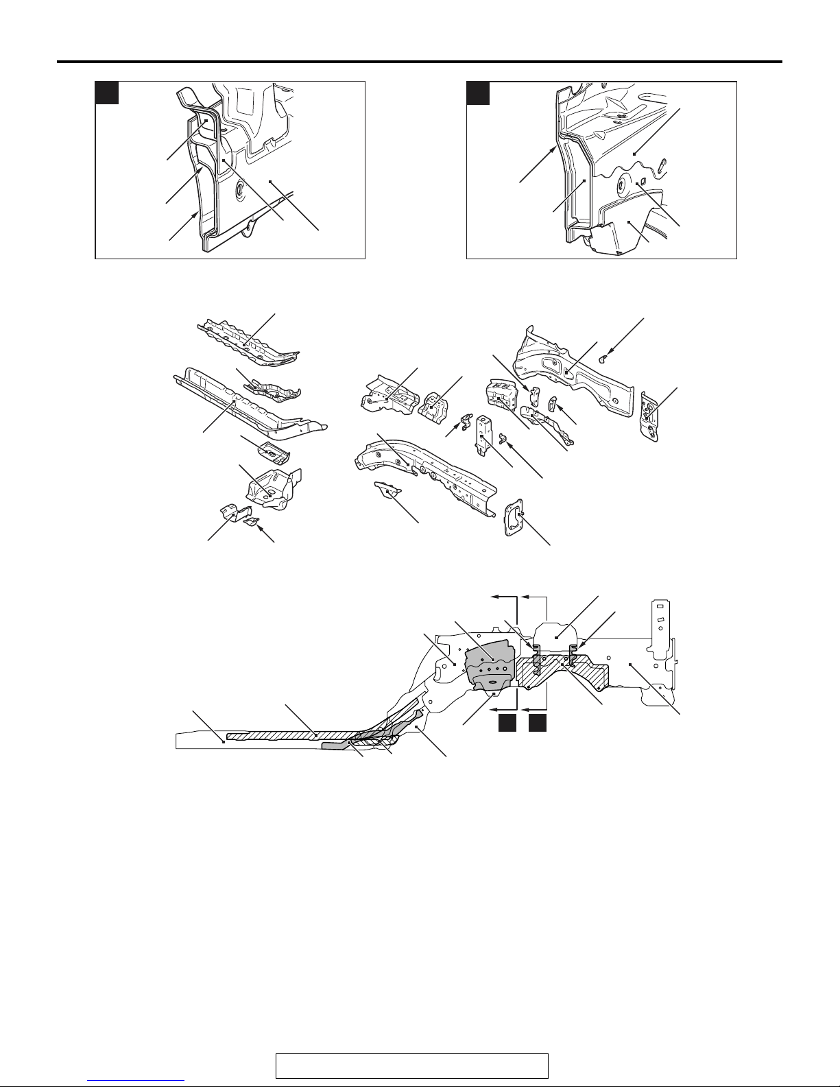
FRONT BODY
HEADLIGHT SUPPORT
• The crush box structure, which has an octagonal
cross-section at the front end of the front side
member, has been adopted. This structure can
effectively absorb energy upon frontal impact and
reduces the vehicle repair cost caused by a light
collision.
9.0 ± 2.0 N·m
80 ± 17 in-lb
2
M4010010001200
• The bolt-on headlight support panel upper is
used to improve maintainability.
-
• An aluminum front bumper reinforcement has
been adopted to improve the body rigidity, han
-
dling stability, and riding comfort.
3
3
5
A
7
4
5
1
20 ± 5 N·m
15 ± 3 ft-lb
1. Front bumper reinforcement
2. Headlight support panel upper
3. Front end crossmember gusset
4. Front end crossmember upper
5. Radiator bracket lower A
6. Front end crossmember bulkhead
7. Radiator bracket lower B
8. Shipping hook front
9. Shipping reinforcement front
10. Front end crossmember lower
6
8
10
9
8
9
A
Crush box
The crush box structure has been changed to
straight type with an octagon cross-section so that
the structure can effectively absorb energy from the
impact at the time of collision.
7
AB701123
AB700911
AB
AB
TSB Revision
BODY CONSTRUCTION
BODY CONSTRUCTION CHARACTERISTICS
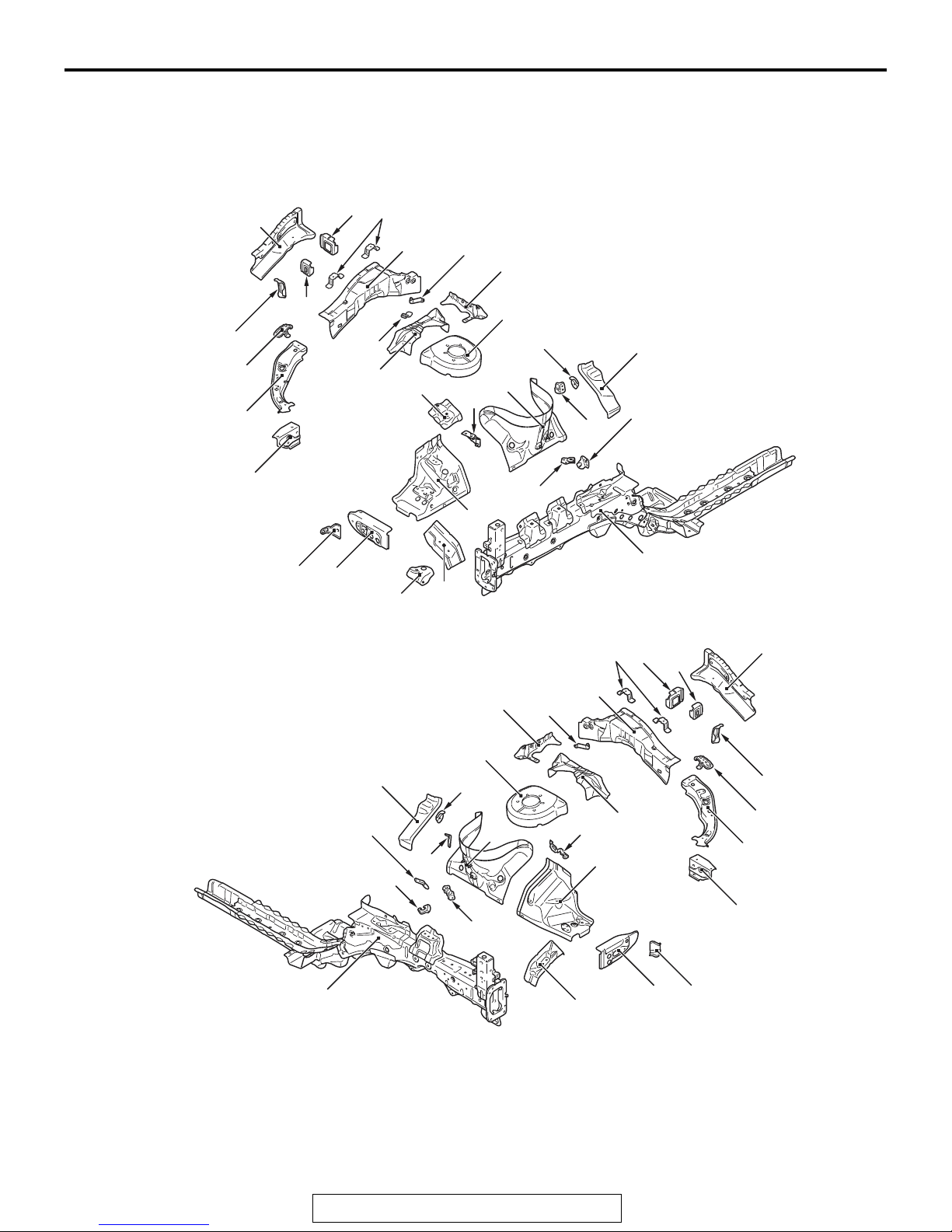
FENDER SHIELD
The padding structure of the front fender bracket has
been adopted to efficiently absorb energy upon
impact by the crushable structure and improve the
pedestrian protection capability.
7
(Right side)
5
8
9
1-9
10
12
(Left side)
6
4
3
11
13
22
2
21
14
20
16
15
18
17
1
19
23
28
27
26
24
25
12
10
8
7
6
9
5
AB700410
AB
14
15
16
4
28
31
32
30
TSB Revision
29
20
33
34
23
13
26
27
3
2
1
AB700409
AB

1-10
BODY CONSTRUCTION
BODY CONSTRUCTION CHARACTERISTICS
1. Upper side bar front
2. Front end upper bar side
3. Front fender bracket
4. Upper frame bulkhead front
5. Fender shield frame upper outer
6. Upper frame bulkhead center
7. Upper frame bulkhead rear
8. Front fender bracket
9. Front upper frame inner
10. Upper frame inner plate
11. Harness bracket
12. Spring house corner gusset
13. Spring house bracket reinforcement
14. Spring house bracket front
15. Spring house panel rear
16. Spring house reinforcement rear
17. Horn bracket
18. Spring house harness bracket
19. Suction hose bracket
20. Spring house panel
21. Power steering reservoir tank bracket
22. Engine mounting bracket upper
23. Front fender shield
24. Engine mounting gusset
25. Condense tank reinforcement
26. Fender gusset
27. Front fender bracket
28. Front sidemember
29. Engine control module bracket
30. Clutch tube bracket <M/T>
31. Harness bracket front
32. Harness bracket rear
33. Relay box bracket
34. Transaxle mounting gusset
TSB Revision
BODY CONSTRUCTION
BODY CONSTRUCTION CHARACTERISTICS
1-11
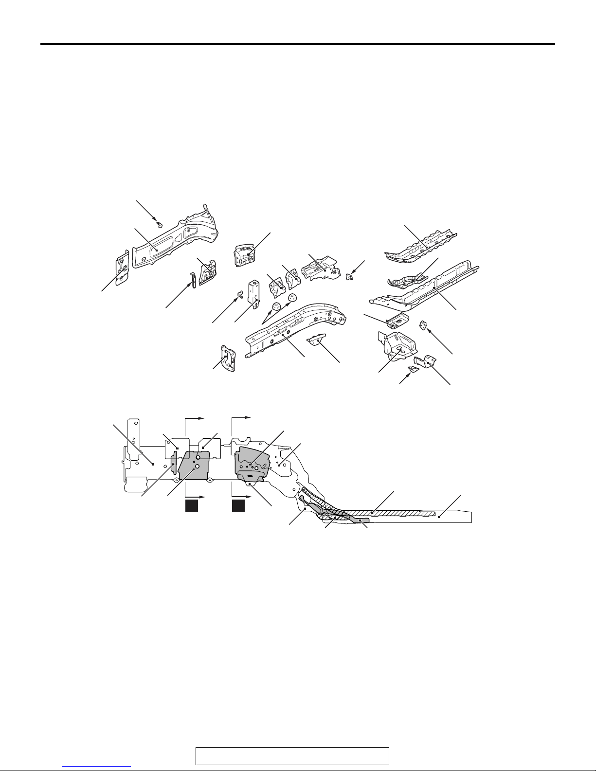
FRONT SIDEMEMBER REINFORCEMENT
• The front sidemember structure has been
changed to a straight frame structure with an
octagon cross section that efficiently absorbs
energy from the impact at the time of collision.
• The front sidemember is supported in three directions by the dash crossmember center, dash
crossmember lower and front sidemember rear in
order to improve the frontal collision characteris
tics, and increase the vehicle body rigidity.
(Right side)
1*
3
2
16
17
22
21
15
20
19
18
• The 590-MPa class high tensile strength steel
panels have been adopted for the front sidemem
ber extension, front sidemember rear bulkhead
and front sidemember rear to improve the body
rigidity.
-
4
23
11
24
5
*
*
6
-
14
*: Indicates 590MPa-high-tensile steel panels.
13
21
16
15
1. Front sidemember extension
2. Front sidemember outer
3. Front brake hose bracket
4. Front sidemember reinforcement rear lower
5. Front sidemember rear bulkhead
6. Front sidemember rear
7. Height sensor bracket
8. Dash crossmember extension lower
9. I plate bracket
10. Front body frame to side sill brace
11. Tie down reinforcement front
12. Front suspension crossmember bracket front
22
A
B
12
13
12
10
9
17
23
4
10
11
13. Front sidemember inner
14. Front sidemember plate
15. Front sidemember bulkhead front
16. Engine mounting bulkhead
17. Front suspension crossmember bulkhead
18. Headlight bracket lower
19. Headlight support panel
20. Engine mounting reinforcement
21. Engine mounting bracket front
22. Engine mounting bracket rear
23. Front sidemember brace upper
24. Front sidemember reinforcement rear
5
7
8
AB700925
AB
6
AB700929
AC
TSB Revision
1-12
BODY CONSTRUCTION
BODY CONSTRUCTION CHARACTERISTICS
A
(Left side)
20
16
2
B
23
2
21
7
13
AB602309
AD
17
12
9
13
AB602310
AD
8
20
6
*
4
5
*
13
3
14
16
15
17
19
18
22
21
10
*
2
*: Indicates 590MPa-high-tensile steel panels.
5
1. I plate bracket
2. Dash crossmember extension lower
3. Front body frame to side sill brace
4. Tie down reinforcement front
5. Front sidemember rear
6. Front sidemember rear bulkhead
7. Front sidemember reinforcement rear lower
8. Front sidemember outer
9. Front brake hose bracket
10. Front sidemember extension
11. Front sidemember plate
1
7
12
11
AB700920
AB
15
19
20
21
14
B
A
12
4
6
3
12. Front suspension crossmember bracket front
13. Front sidemember inner
14. Front sidemember brace upper
15. Transaxle mounting bracket
16. Connector bracket
17. Headlight support panel
18. Headlight bracket lower
19. Front suspension crossmember bulkhead
20. Transaxle mounting bulkhead rear
21. Transaxle mounting bulkhead front
22. Front sidemember reinforcement
22
13
AB700931
AC
TSB Revision
BODY CONSTRUCTION
BODY CONSTRUCTION CHARACTERISTICS
1-13
A
13
15
8
22
20
AB700583
AC
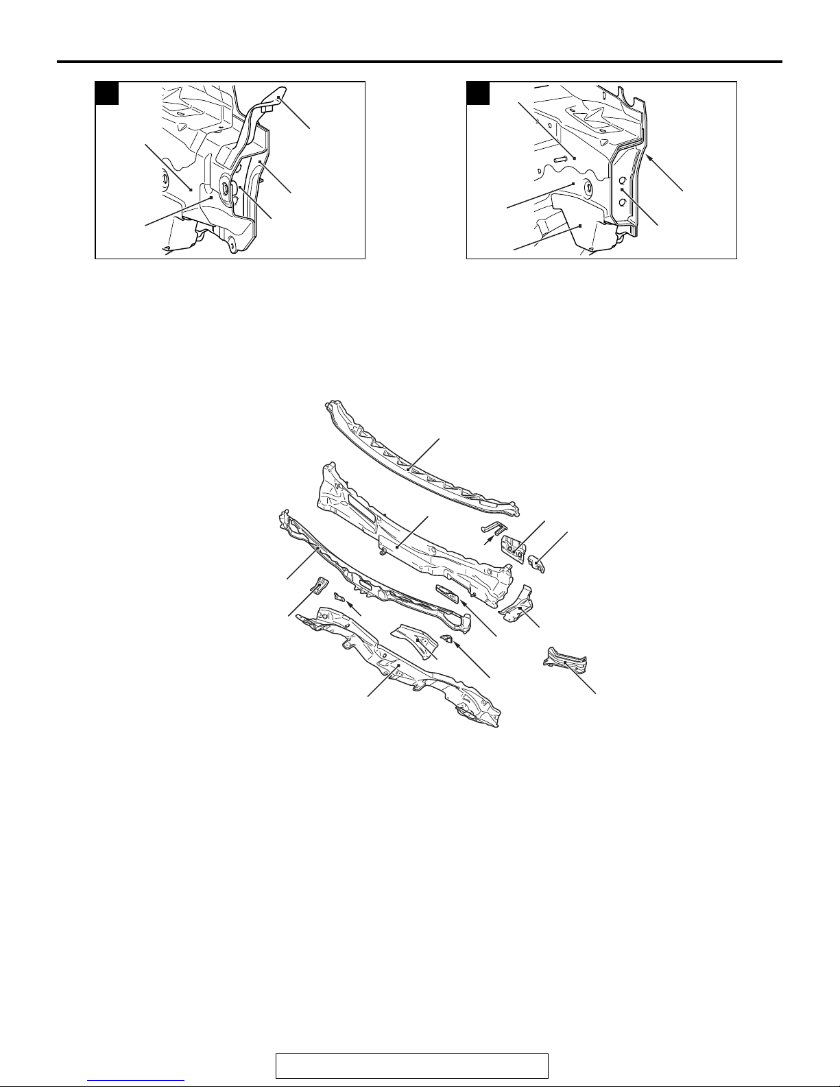
FRONT DECK
• The impact absorbing opening on the cowl top
outer reinforcement upper has been added to effi
ciently absorb energy upon impact and improve
the pedestrian protection capability.
B
14
13
8
19
12
• Rigidity was heightened and driving stability was
improved by bonding the fender shield frame
-
upper outer and front pillar by the upper frame to
front pillar brace.
AB700584
6
AC
4
3
1. Cowl top panel lower
2. Wiper B bracket
3. Cowl top stay bracket rear
4. Cowl top outer reinforcement upper
5. Cowl top panel inner
6. Cowl top panel outer
7. Deck crossmember stay bracket
5
8
9
7
2
10
11
13
12
1
8. Brake pedal support bracket
9. Clutch pedal support bracket <M/T>
10. Upper frame extension inner
11. Brake pedal support reinforcement
12. Front fender bracket
13. Cowl top outer reinforcement lower
14. Upper frame to front pillar brace
14
AB602289
AC
TSB Revision
1-14
BODY CONSTRUCTION CHARACTERISTICS
BODY CONSTRUCTION
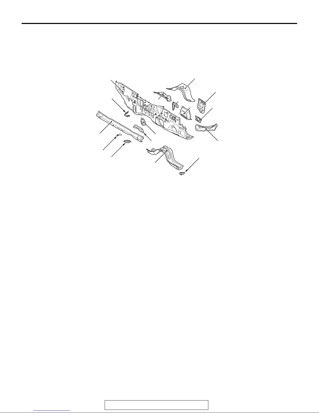
DASH PANEL
The 590-MPa class high tensile strength steel panels
have been adopted for the dash crossmember cen
ter, dash crossmember extension, dash panel reinforcement and dash crossmember side to improve
the body rigidity.
-
3*
2
*: Indicates 590MPa-high-tensile steel panels.
1. Brake tube bracket
2. Harness bracket
3. Dash crossmember center
4. Dash crossmember extension
5. Canister bracket
6. Dash heat protector bracket
7. Dash panel
8. Backbone reinforcement front
7
9
12*
6
8
10
11
13
5
4*
1
15
14*
16
AB700934
9. Dash panel lower
10. Accelerator pedal bracket
11. Steering shaft bracket
12. Dash panel reinforcement
13. Clutch pedal reinforcement lower <M/T>
14. Dash crossmember side
15. Dash crossmember lower bulkhead
16. Dash crossmember lower
AB
TSB Revision
BODY CONSTRUCTION
BODY CONSTRUCTION CHARACTERISTICS
1-15
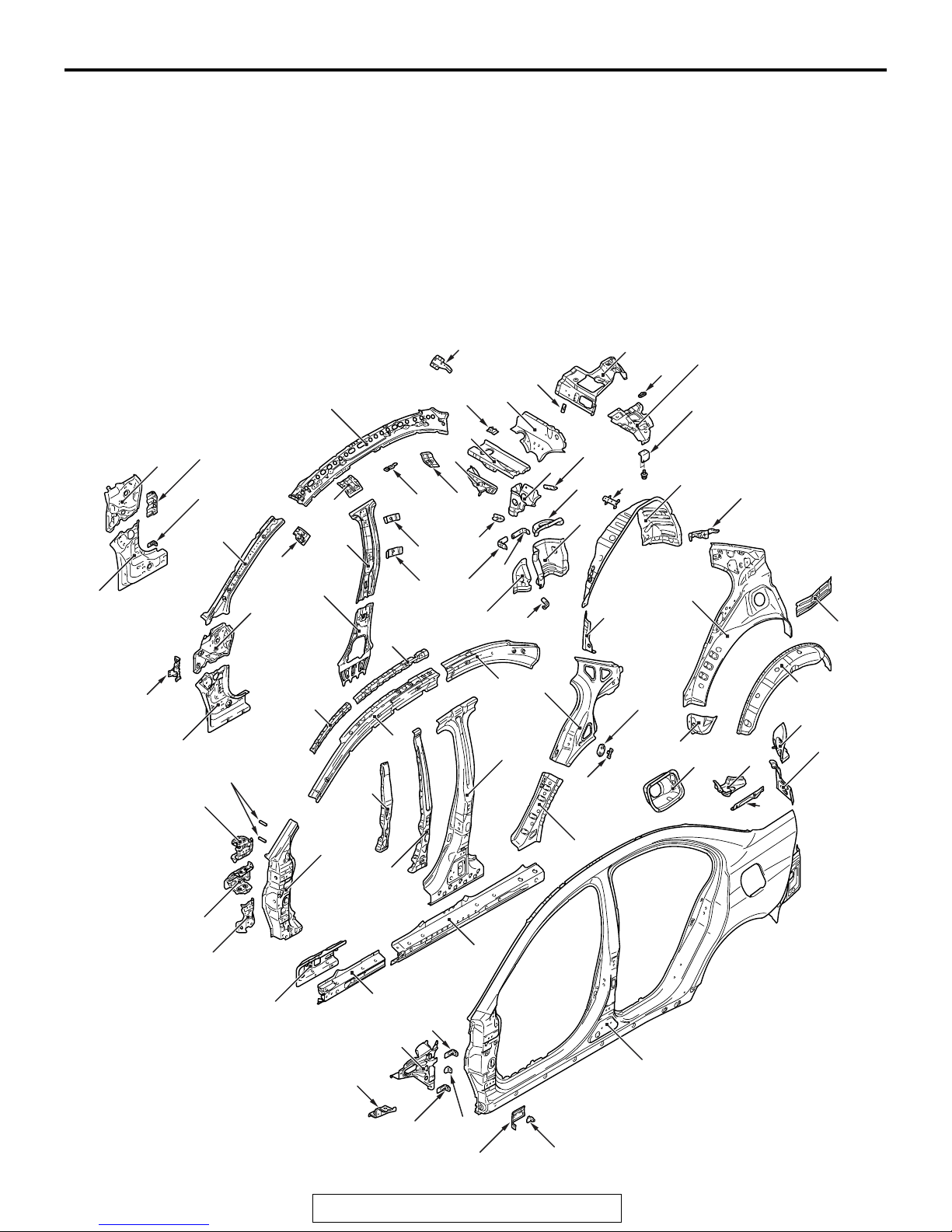
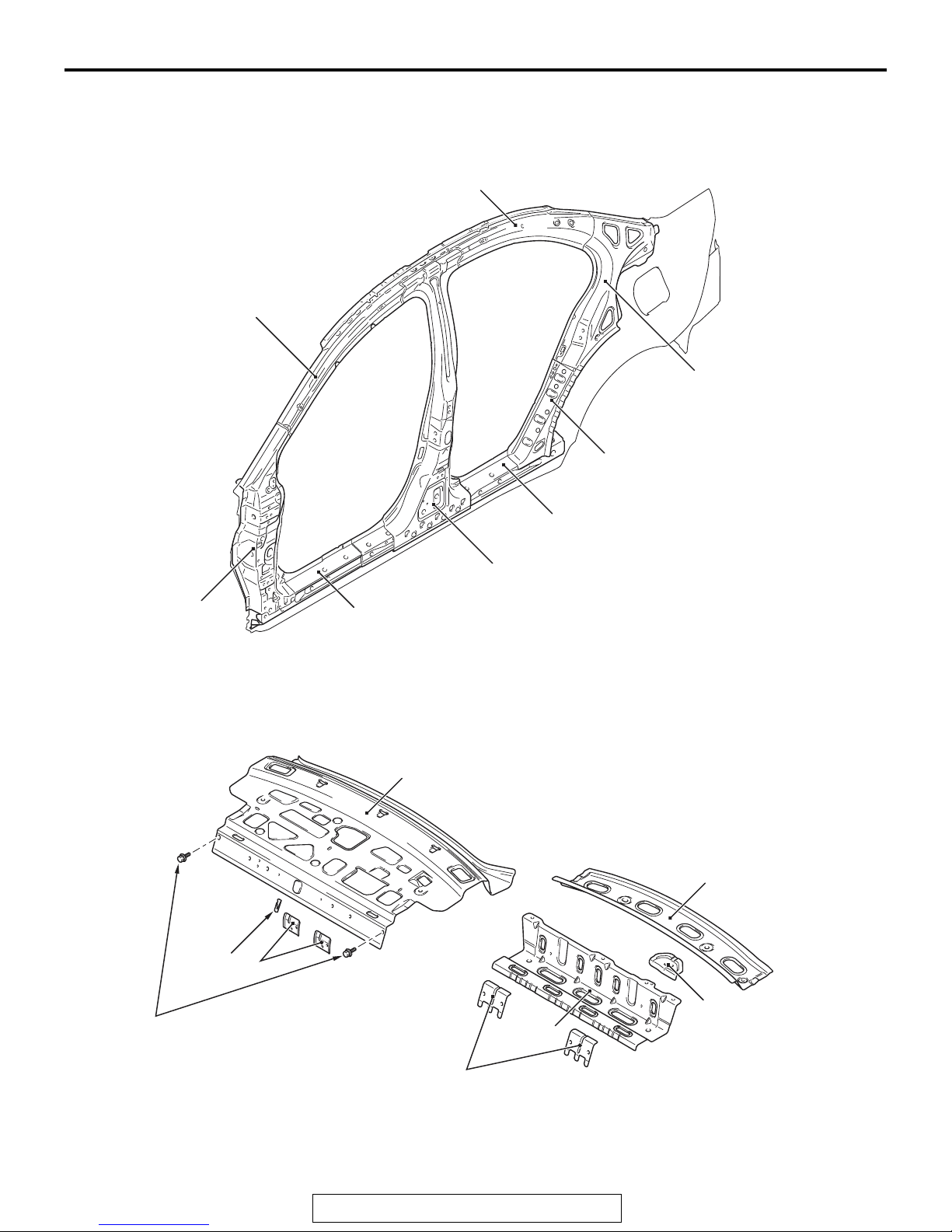
SIDE BODY
SIDE STRUCTURE
• The 590-MPa class high tensile strength steel
panels or 980-MPa class ultra high tensile
strength steel panels have been adopted for the
front pillar, center pillar, side sill, and roof side rail
to improve the body rigidity.
• Rigidity was heightened and driving stability was
improved by bonding the roof bow and roof rail
and the roof side rail inner by the roof rail exten
sion.
15*
5
2
4
12
6*
8*
11
1
2
7
13
10
9
64*
-
25
14
• A rear shelf lower brace is used to connect the
spring house middle panel and rear shelf upper
brace, so that the body rigidity, handling stability,
and riding comfort are improved.
• The number of the spot welding points at the door
opening has been increased to heighten the body
rigidity and to improve handling stability.
16
23
21
22
17
19
18
20
24
28
27
29
35
36
38
34
26
30
31
32
37
33
40
M4010011001087
39
3
63*
1
62
66
61
58
67*
60
59
57
56**
54
*: Indicates 590MPa-high-tensile steel panels.
**: Indicates 980MPa-ultra-high-tensile steel panels.
65*
53
52
52
51
55**
50
69
68
70
49
72
73
71
48
41
47
45
46
42
43
44
AB700954
AB
TSB Revision

1-16
BODY CONSTRUCTION
BODY CONSTRUCTION CHARACTERISTICS
1. Front pillar inner lower
2. Front pillar inner center
3. Hood opener bracket (Left side)
4. Cowl side trim bracket (Right side)
5. Deck crossmember bracket (Right side)
6. Front upper inner pillar
7. Center pillar inner lower
8. Center pillar inner upper
9. Center pillar seat belt reinforcement lower
10. Center pillar seat belt reinforcement upper
11. Roof rail front extension
12. Roof rail center extension <Vehicles without sunroof
(aluminum panel)>
13. Bracket C <Vehicles with sunroof (steel panel)>
14. Roof rail rear extension
15. Roof side rail inner
16. Harness bracket (Right side)
17. Rear shelf upper brace
18. Rear seat belt reinforcement
19. Nut plate <Vehicles with subwoofer>
20. Subwoofer upper bracket <Vehicles with subwoofer>
21. Rear seat hook A
22. Rear seatback brace rear
23. Rear seatback plate reinforcement
24. Rear seatback brace bulkhead
25. Rear seatback brace front
26. Rear spring house reinforcement upper front
27. Rear shelf lower brace
28. Rear spring house reinforcement upper rear
29. Rear spring house bracket
30. Trunk trim bracket
31. Washer tank center bracket (Left side)
32. Spring house middle front panel (Left side)
33. Filler pipe mounting bracket (Left side)
34. Spring house middle panel
35. Harness bracket (Left side)
36. Rear wheel house panel inner
37. Rear wheel house panel front lower outer
38. Curtain air bag bracket
39. Quarter panel lower inner (Left side)
40. Quarter inner panel
41. Quarter panel extension inner
42. Quarter panel extension lower outer
43. Rear combination light housing
44. Quarter corner panel
45. Quarter outer upper extension
46. Quarter outer upper side extension
47. Fuel filler neck bracket (Left side)
48. Side outer panel
49. Fender bracket
50. Fender bracket lower
51. Front fender bracket
52. Cowl side trim bracket
53. Front upper outer frame rear
54. Upper frame outer reinforcement
55. Side sill reinforcement outer rear
56. Side sill reinforcement outer front
57. Side sill inner support front
58. Front pillar reinforcement lower
59. Front door hinge reinforcement lower
60. Front pillar reinforcement center bulkhead
61. Front door hinge reinforcement upper
62. Deck support pipe (Left side)
63. Front pillar support
64. Roof side rail support
65. Roof side rail reinforcement front
66. Rear door hinge reinforcement support
67. Rear door hinge reinforcement
68. Center pillar reinforcement
69. Roof side rail reinforcement rear
70. Rear pillar reinforcement
71. Flap gate striker reinforcement
72. Nut plate
73. Rear pillar reinforcement lower
TSB Revision
BODY CONSTRUCTION
BODY CONSTRUCTION CHARACTERISTICS
SIDE STRUCTURE REINFORCEMENT
The ring structure of the side structure reinforcement
has been adopted to improve the collision characteristics and the rigidity of the whole vehicle.
Roof side rail reinforcement rear
Roof side rail reinforcement front
1-17
Rear pillar reinforcement
Rear pillar reinforcement lower
Front pillar
reinforcement lower
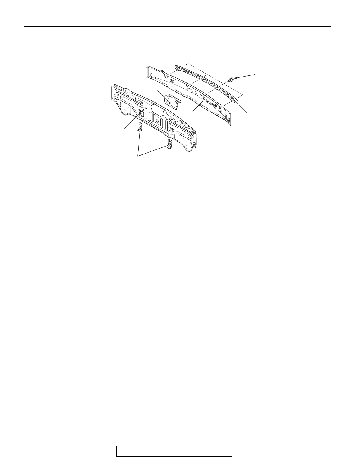
REAR BODY
REAR DECK
Side sill reinforcement outer rear
Center pillar reinforcement
Side sill reinforcement outer front
AB700608
M4010012000764
AB
3
4
2
1
18 ± 7 N·m
13 ± 5 ft-lb
1. Washer tank bracket upper
2. Rear seat hook A
3. Rear shelf panel
4. Rear shelf reinforcement
TSB Revision
6
7
5. Seat belt reinforcement center
6. Rear shelf extension
7. Rear seatback reinforcement
5
AB700406
AB
1-18
REAR END PANEL
BODY CONSTRUCTION
BODY CONSTRUCTION CHARACTERISTICS
5.0 ± 1.0 N·m
44 ± 9 in-lb
3
2
1
1. Rear bumper side bracket
2. Rear end panel inner
3. Trunk lid striker reinforcement
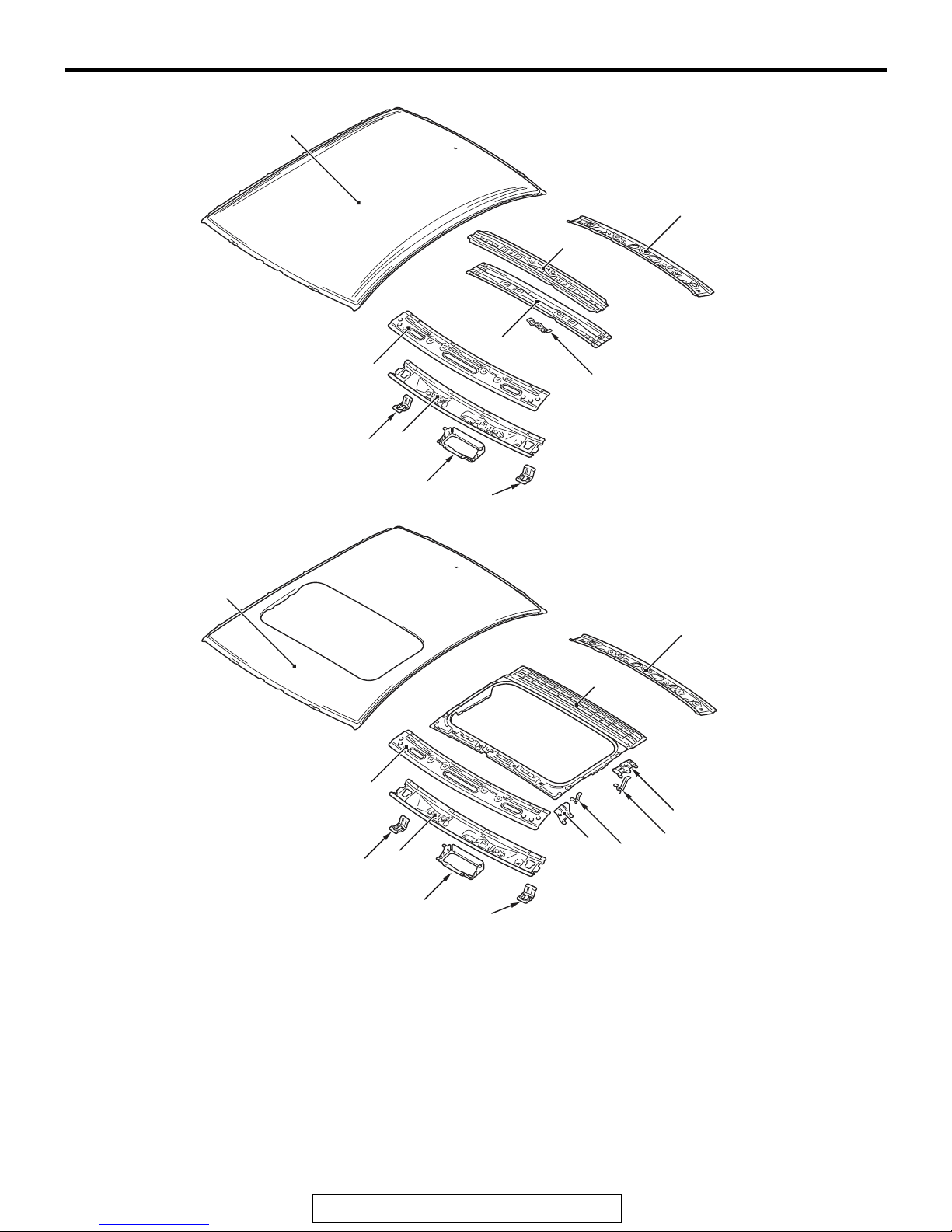
ROOF
• An aluminum roof panel has been adopted to
improve lightweightness for greater handling sta
bility. <Vehicles without sunroof (aluminum
panel)>
• The closed section structure has been adopted
for the roof rail front and the roof bow center to
heighten body rigidity, improve handling stability
and riding comfort, and to reduce vibration and
noise.
4
4. Rear end panel outer
5. Rear bumper reinforcement
5
• The 590-MPa class high tensile strength steel
-
panel has been adopted for the roof bow center
lower to improve the body rigidity. <Vehicles with
out sunroof (aluminum panel)>
AB700570
M4010013001306
AB
-
TSB Revision
BODY CONSTRUCTION CHARACTERISTICS
<Vehicles without sunroof (aluminum panel)>
5
1
BODY CONSTRUCTION
8*
4
3
1-19
6
7
9
*: Indicates 590MPa-high-tensile steel panels.
<Vehicles with sunroof (steel panel)>
5
1. Sunvisor bracket
2. Reading light bracket
3. Roof rail front lower
4. Roof rail front upper
5. Roof panel
6. Roof rail rear
7. Roof bow center upper
2
1
AB700936
AB
6
10
4
11
13
12
AB700863
AE
3
1
2
1
8. Roof bow center lower
9. Dome light bracket
10. Roof panel reinforcement
11. Set rear bracket
12. Bracket A
13. Bracket B
14. Set front bracket
14
TSB Revision
1-20
BODY CONSTRUCTION
BODY CONSTRUCTION CHARACTERISTICS
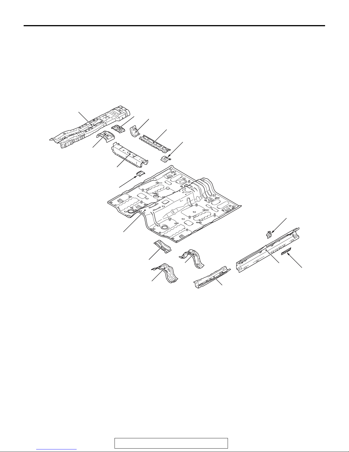
UNDER BODY
FRONT FLOOR
The 590-MPa class high tensile strength steel panels
have been adopted for the front floor crossmember
front and front floor sidemember, and the 980-MPa
class ultra high tensile strength steel panels for the
front floor side sill inner, to improve the body rigidity.
5
4
3
*
2
6
7
M4010014001202
8
9
1
16
*: Indicates 590MPa-high-tensile steel panels.
**: Indicates 980MPa-ultra-high-tensile steel panels.
1. Front floor
2. Front floor crossmember front reinforcement
3. Front floor crossmember front
4. Parking brake lever reinforcement
5. Backbone reinforcement
6. Parking brake cable reinforcement
7. Seat center bracket rear
8. Front floor crossmember rear
15
10
14
12
**
11
13
*
9. Seat side bracket rear
10. Seat belt reinforcement
11. Front floor side sill inner center reinforcement
12. Front floor side sill inner
13. Front floor sidemember
14. Front floor crossmember rear center
15. Front floor crossmember front
16. Front floor reinforcement lower (Right side)
AB700937
AB
TSB Revision

BODY CONSTRUCTION
BODY CONSTRUCTION CHARACTERISTICS
1-21
REAR FLOOR
• The 590-MPa class high tensile strength steel
panels have been adopted for the rear floor
extension and rear seat crossmember to improve
the body rigidity.
7
5
6
4
2
1*
• The rear floor rear end crossmember has been
straightened to heighten body rigidity, improve
handling stability and riding comfort, and to
reduce vibration and noise.
8
3
9
16
*: Indicates 590MPa-high-tensile steel panels.
1. Rear floor extension
2. Rear seat under floor
3. Rear floor pan rear
4. Rear seatback bracket lower
5. Rear floor crossmember upper
6. Battery bracket rear floor front
7. Battery bracket rear floor
8. Spare tire bracket
9. Rear floor rear end crossmember
15*
14
13
11
10
11
12
17
16
10. Rear floor crossmember front
11. Fuel tank rear bracket
12. Rear seat belt reinforcement (Left side)
13. Rear seat belt reinforcement (Right side)
14. Rear seat crossmember bulkhead inner
15. Rear seat crossmember
16. Sidemember front floor extension
17. Rear floor sidemember
AB700404
AB
TSB Revision
1-22
BODY CONSTRUCTION CHARACTERISTICS
BODY CONSTRUCTION
REAR FLOOR SIDEMEMBER
REINFORCEMENT
The 590-MPa class high tensile strength steel panels
have been adopted for the rear floor sidemember
reinforcement, rear floor sidemember extension, rear
floor side sill inner and rear floor sidemember bulk
head to improve the body rigidity.
-
33
2
32
29
6*
30
31
10
5
4
7
28
9
11
12*
13
16
27
8
15
14
26
3
1
23
25
24*
22
17
*: Indicates 590MPa-high-tensile steel panels.
A
23
18
20
24
22
6
25
19
21
15
28
27
19
20
18*
AB700942
AB
10
30
29
31
B
12
11
AB700587
AB700953
AC
TSB Revision
BODY CONSTRUCTION
BODY CONSTRUCTION CHARACTERISTICS
1-23
1. Rear floor side panel
2. Rear bumper beam reinforcement
3. Rear floor crossmember extension rear
4. Rear suspension bracket center
5. Rear suspension center reinforcement
6. Rear floor sidemember reinforcement
7. Rear floor crossmember extension rear upper
8. Rear floor crossmember extension rear
9. Muffler hanger rear
10. Shipping pipe
11. Shipping bracket reinforcement
12. Rear floor sidemember extension
13. Rear bumper support
14. Canister bracket (Left side)
15. Rear spring house panel lower
16. ABS sensor bracket
17. Brake hose bracket
A
1
6
18. Rear floor side sill inner
19. Rear suspension bracket front
20. Trailing arm bracket lower
21. Rear floor sidemember lower
22. Rear floor sidemember extension front
23. Rear tie down plate
24. Rear floor sidemember bulkhead
25. Trailing arm bracket
26. Trailing arm bulkhead
27. Rear floor sidemember rear reinforcement
28. Rear suspension center bulkhead
29. Rear floor sidemember bulkhead rear
30. Rear suspension bracket rear
31. Pipe nut
32. Hydraulic unit bracket front (Right side)
33. Hydraulic unit bracket rear (Right side)
B
1
21
25
20
18
AB700589
AC
21
29
15
AB700588
AB
TSB Revision
1-24
BODY CONSTRUCTION
BODY CONSTRUCTION CHARACTERISTICS
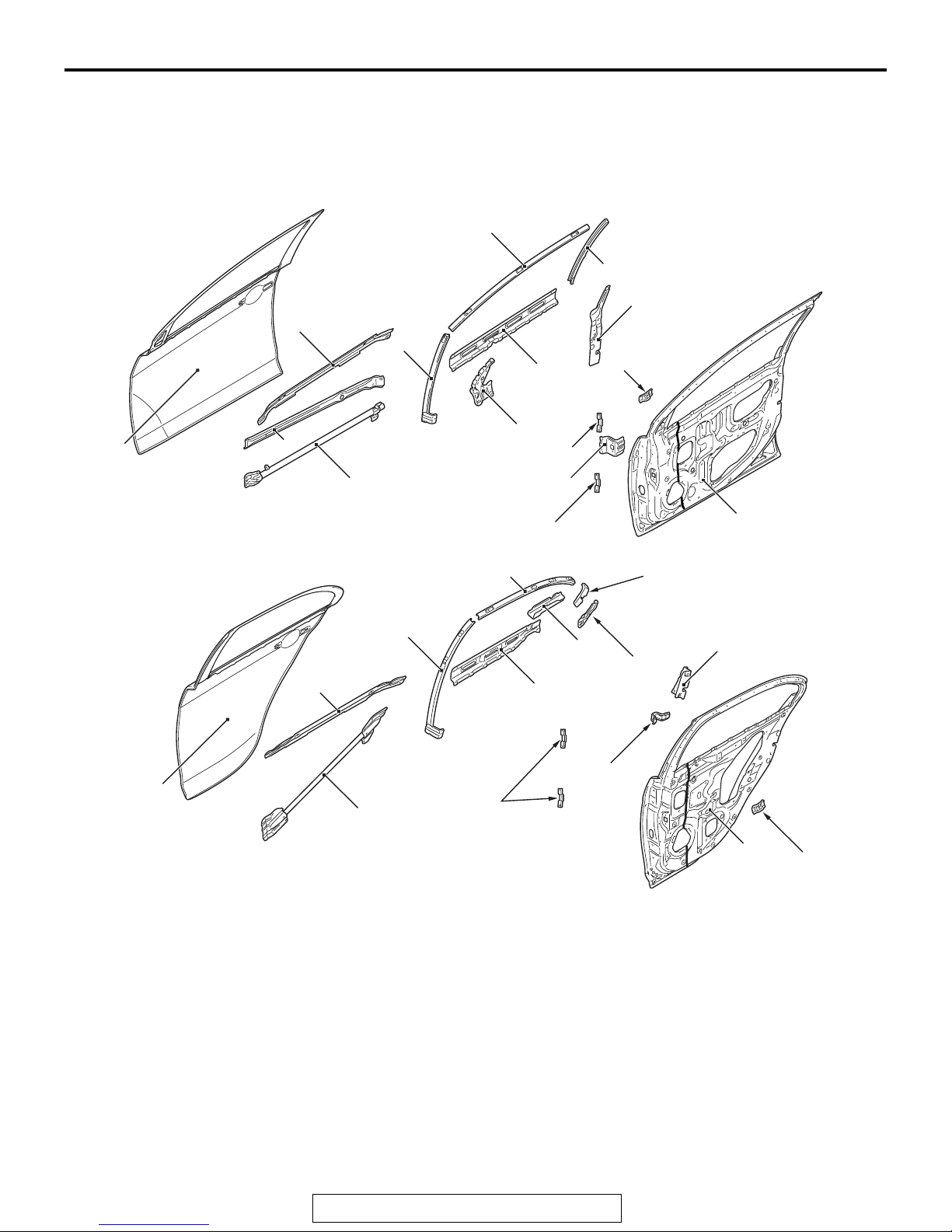
DOOR
An uneven thickness steel sheet* has been used for
the front and rear door panel inners to make the forward part of the vehicle thicker for reduction in vehicle weight and higher rigidity.
(Front door)
2
5
1
(Rear door)
3
4
M4010015000893
NOTE: *: A steel sheet of varying thickness that is
welded into one steel sheet.
6
7
8
9
11
10
12
13
14
AB602334
AB
19
12
23
16
15
1. Front door panel outer
2. Front door beltline outer reinforcement
3. Front door outer stiffener
4. Front door side door beam
5. Front door window front sash
6. Front door window upper sash
7. Front door window rear sash
8. Front door latch reinforcement
9. Front door beltline inner reinforcement
10. Front door mirror reinforcement
11. Front door inside handle bracket
12. Nut plate
13. Front door checker reinforcement
14. Front door panel inner
17
18
21
24
22
20
25
12
27
15. Rear door panel outer
16. Rear door beltline outer reinforcement
17. Rear door side door beam
18. Rear door window front sash
19. Rear door window upper sash
20. Rear door beltline inner reinforcement
21. Rear door beltline bracket
22. Rear door sash reinforcement
23. Rear door stat corner bracket
24. Rear door latch reinforcement
25. Rear door window sash lower bracket
26. Rear door inside handle bracket
27. Rear door panel inner
26
AB700413
AB
TSB Revision
BODY CONSTRUCTION
SILENCER APPLICATION LOCATIONS
1-25
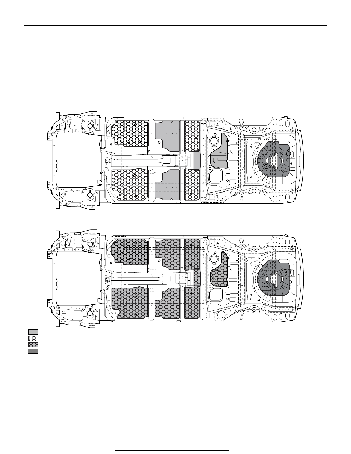
SILENCER APPLICATION LOCATIONS
A silencer (MD-12, RSS and melting sheet) has been
affixed on the upper surface of the floor for vibration
damping.
NOTE: .
•
MD-12 is a high performance sheet composed of
asphalt applied with mica and thermosetting resin
for improving anti-vibration performance.
<GSR>
M4010005001271
•
RSS (Rubber Special Sheet) is a product name
of Nihon Tokushu Toryo Co., Ltd. The product
features the same performance as a steel sheet
sandwich type and refers to a heat cured resin
sheet that is molded into a sheet with a uniform
thickness. It contains degenerating resin and filler
with asphalt and rubber as the main contents.
<MR>
: 1.6 mm (
: 1.6 mm (
: 3.2 mm (
: 1.6 mm (
[
Place three 1.6 mm (
0.063 in)
0.063 in)
0.126 in)
0.063 in)
thick melting sheet
thick MD-12 [Place a 1.6 mm (
thick MD-12 [Place two 1.6 mm (
thick melting sheet and 2.0 mm (
0.063 in)
melting sheet one on top of the next.
0.063 in)
0.063 in)
0.079 in)
NOTE: [ ] indicates the number of melting sheets that
are used for repair.
melting sheet.
melting sheet one on top of another.
thick RSS
]
]
AB700568
AB700568
]
AB700569
AB
AB
TSB Revision
1-26
BODY CONSTRUCTION
FOAMING MATERIAL USAGE LOCATIONS
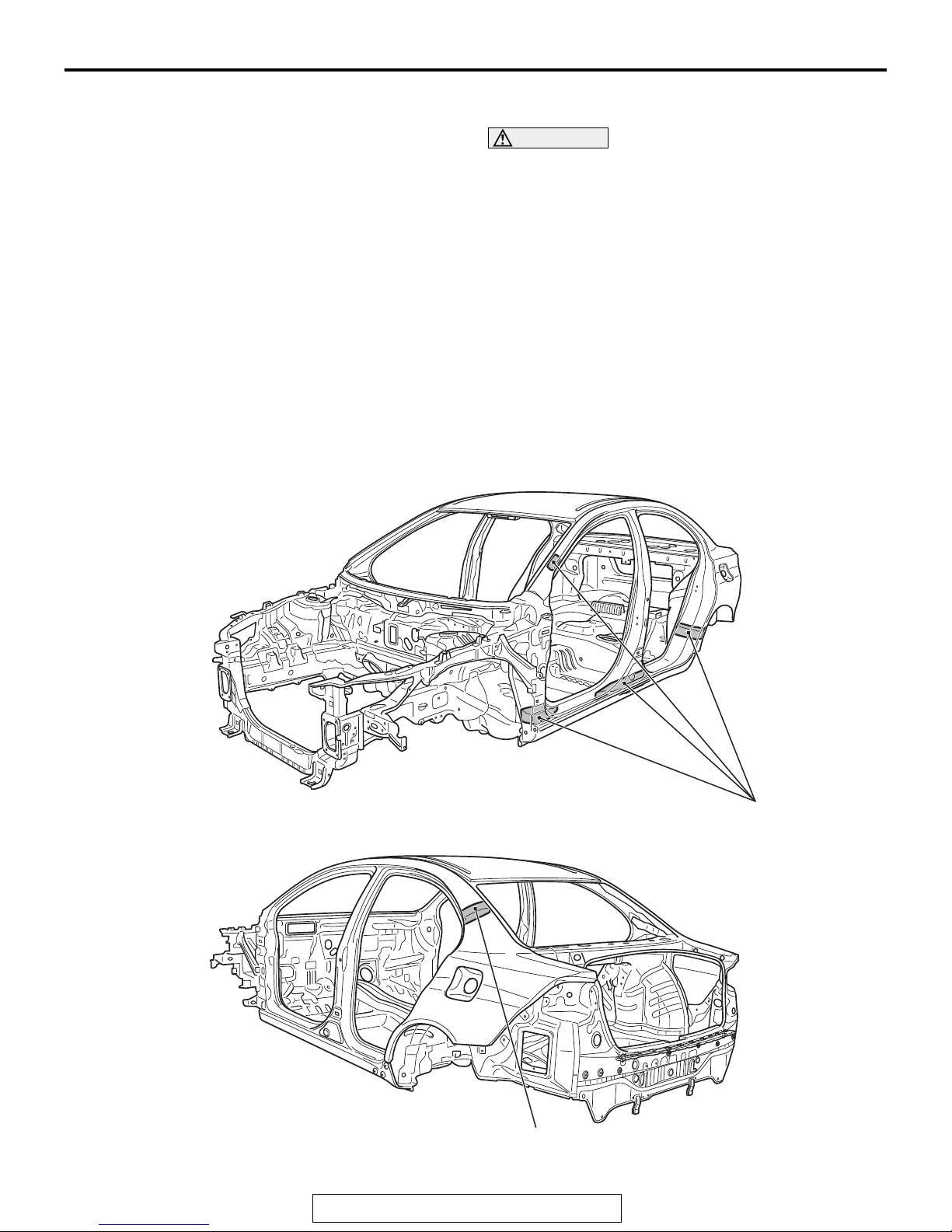
FOAMING MATERIAL USAGE LOCATIONS
The sound dampening foam material have been
adopted to the upper and lower sections of the front
pillar, center pillar lower section, rear pillar and wheel
house arch inside to shield from external noise.
M4010006000163
CAUTION
The sound dampening foam material may burn
when heated. Always observe the following
instructions:
• Never use a gas burner to burn the areas
where sound dampening foam material is
used.
• When cutting the parts which are provided
with sound dampening foam material, ensure
to use tools (air saw, etc.) that do not gener
ate fire.
• If there are residual sound dampening foam
material remaining on the cut section (body
side), remove the sound dampening foam
material from periphery of the welding area
before welding work.
-
TSB Revision
Sound dampening foam material
Sound dampening foam material
AB700801
AB
BODY CONSTRUCTION
STIFFENER AND DAMP SHEET APPLICATION LOCATIONS
1-27
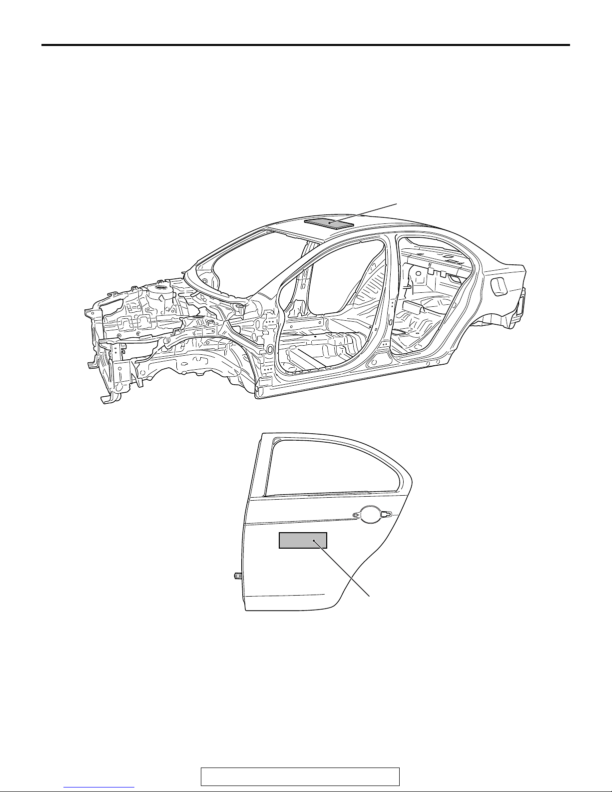
STIFFENER AND DAMP SHEET APPLICATION LOCATIONS
M4010001400263
A damp sheet (roof insulator) <Vehicles without sunroof (aluminum panel)> on the inner side of the roof
panel and a stiffener on the inner side of the rear
door panel outer have been adopted for higher sur
face rigidity.
-
NOTE: .
•
The main contents of a stiffener are epoxy resin.
It comes in a sheet form and contains a mixture
of glass fiber and filler, and cures (stiffens) when
heated.
•
No spare part of the stiffener for repair is available in the field. If the stiffener is damaged,
replace it together with the panel.
Damp sheet (roof insulator)
AB700461
(Rear door)
Stiffener
AB700893
AB700892
AB
AB
TSB Revision
1-28
BODY CONSTRUCTION
THEFT PROTECTION
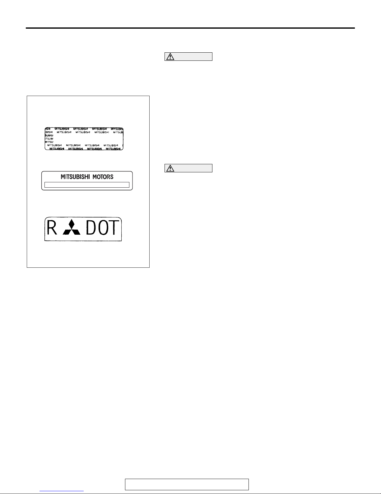
Theft protection plate and label
For original parts
For replacement parts
THEFT PROTECTION
CAUTION
When replacing a part that has the theft protection plate,
label or stamp on it, be sure that the part has either A or B
shown in the figure. It is illegal if both A and B are
attached, or neither A nor B is attached.
In order to protect against theft, a Vehicle Identification Number
(VIN) is attached as a plate or label to the following major parts
of the engine, transaxle and main outer panels: Engine cylinder
block, Transaxle housing, Front fender, Hood, Trunk lid,
Bumpers, Side outer panel, Doors. In addition, a theft-protec
tion label is attached to replacement parts for main outer panels. The same data is stamped into replacement parts for the
engine and the transaxle.
CAUTION
Cautions regarding panel repairs:
• When repainting original parts, do so after first masking
the theft-protection label. After painting, be sure to peel
off the masking tape.
• The theft-protection label for replacement parts is covered by masking tape, so such parts can be painted as
is. The masking tape should be removed after painting
is finished.
• The theft-protection label should not be removed from
original parts or replacement parts.
M4010017000145
-
AC704152
.
AB
TSB Revision
 Loading...