

Page 1
2003
Body Repair
Return to Main Menu
GROUP INDEX
MITSUBISHI
LANCER
EVOLUTION VIII
TECHNICAL
INFORMATION
MANUAL
FOREWORD
This manual has been prepared as an introduction to
the specifications, features, construction, functions,
and other areas of the new 2003 LANCER EVOLUTION VIII. It includes Technical Information and Body
Repair Service. The Body Repair sections immediately follow Group 55 - Heater, Air Conditioning and Ventilation.
Please read this manual carefully so that it will be of
assistance for your service and sales activities. Please
note the following service manuals are also available
and should be used in conjunction with this manual.
General . . . . . . . . . . . . . . . . . . . . . . .
Engine . . . . . . . . . . . . . . . . . . . . . . . .
Lubrication . . . . . . . . . . . . . . . . . . . .
Fuel . . . . . . . . . . . . . . . . . . . . . . . . . .
Engine Cooling . . . . . . . . . . . . . . . . .
Intake and Exhaust . . . . . . . . . . . . . .
Engine Electrical. . . . . . . . . . . . . . . .
Engine and Emission Control . . . . .
Clutch. . . . . . . . . . . . . . . . . . . . . . . . .
Manual Transaxle . . . . . . . . . . . . . . .
Propeller Shaft . . . . . . . . . . . . . . . . .
Front Axle . . . . . . . . . . . . . . . . . . . . .
00
11
12
13
14
15
16
17
21
22
25
26
SERVICE MANUAL MSSP-206B-2003
PARTS CATALOG BUM6K103A
No part of this publication may be reproduced, stored in any retrieval
system of transmitted, in any form or by any means, including but not
limited to electronic, mechanical photocopying, recording or otherwise,
without the prior written permission of Mitsubishi Motors Corporation.
!2003 Mitsubishi Motors Corporation
All Rights, Reserved
Printed in USA
MSSP-260B-2003
Rear Axle . . . . . . . . . . . . . . . . . . . . . .
Wheel and Tire . . . . . . . . . . . . . . . . .
Power Plant Mount . . . . . . . . . . . . . .
Front Suspension . . . . . . . . . . . . . . .
Rear Suspension . . . . . . . . . . . . . . .
Service Brakes . . . . . . . . . . . . . . . . .
Parking Brakes . . . . . . . . . . . . . . . . .
Steering . . . . . . . . . . . . . . . . . . . . . . .
Body. . . . . . . . . . . . . . . . . . . . . . . . . .
Exterior . . . . . . . . . . . . . . . . . . . . . . .
Interior and Supplemental
General . . . . . . . . . . . . . . . . . . . . . . .
Restraint System (SRS) . . . . . . . . . .
Chassis Electrical . . . . . . . . . . . . . . .
Heater, Air Conditioning
. . . . . . . . . . . . . . . . . . . . . . . . . . . . . . . . .
. . . . . . . . . . . . . . . . . . . . . . . . . . . . . . . . .
. . . . . . . . . . . . . . . . . . . . . . . . . . . . . . . . . . . . . . . . . . . . . . . . . . . . . . . . . . . . . . . . . .
and Ventilation . . . . . . . . . . . . . . . . .
27
31
32
33
34
35
36
37
42
51
52
54
55
Page 2

GROUP 52B
SUPPLEMENTAL
RESTRAINT
SYSTEM (SRS)
CONTENTS
52B-1
GENERAL DESCRIPTION. . . . . . . . . 52B-2
SYSTEM OPERATION. . . . . . . . . . . . 52B-7
SRS-ECU . . . . . . . . . . . . . . . . . . . . . . 52B-10
Page 3
52B-2
SUPPLEMENTAL RESTRAINT SYSTEM (SRS)
GENERAL DESCRIPTION
GENERAL DESCRIPTION
M2521000100132
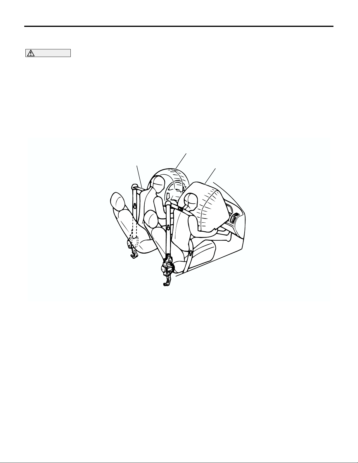
CAUTION
• Driver and front passenger air bags and seat belt pre-tensioners deploy and operate in all head-on
collisions that exceed the threshold to activate the SRS system.
• The specific value is the equivalent impact when a vehicle collides against a concrete (fixed) wall
at approximately 25 km/h (16 mph) or more.
• The SRS and pre-tensioner may not work under the following conditions:
• A head-on collision is less than the specific value.
• A vehicle collides on its rear end.
• A vehicle rolls over or is in a similar position.
DRIVER'S AIR BAG
SEAT BELT PRE-TENSIONER
PASSENGER'S
(FRONT) AIR BAG
Driverís and front passengerís air bags and seat
belts with pre-tensioner are standard, increasing the
passive safety level.
.
SUPPLEMENTAL RESTRAINT SYSTEM (SRS)
The SRS is designed to supplement the front seat
belts. It eliminates or reduces or injury to the front
passenger(s) by deploying air bag(s) in case of a
head-on collision.
.
AC211587
AB
SEAT BELT WITH PRE-TENSIONER
The seat belts with pre-tensioner work simultaneously with the SRS. The pre-tensioner takes up
seat belt slack immediately when a collision takes
place by that restraining the front passengers sooner
than the SRS. This prevents the passengers from
moving forwards.
Page 4
SUPPLEMENTAL RESTRAINT SYSTEM (SRS)
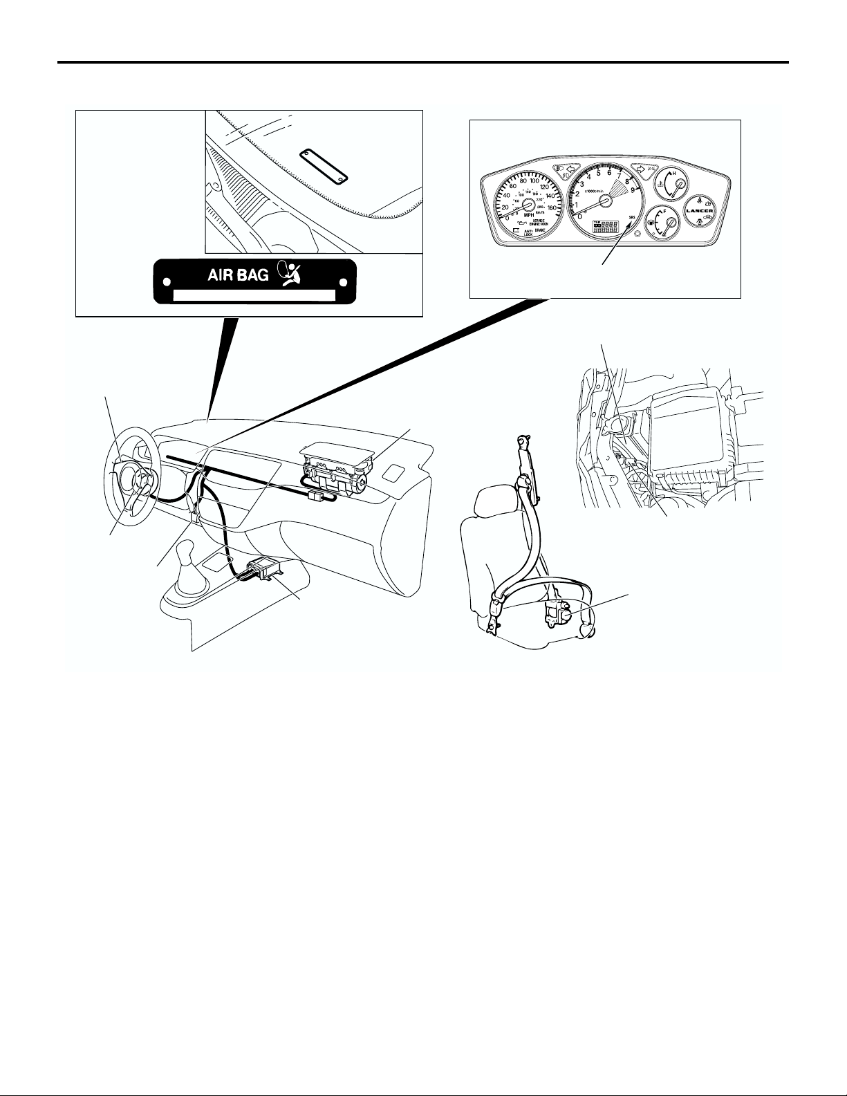
CONSTRUCTION DIAGRAM
VEHICLES
IDENTIFICATION
CODE CHART
PLATE
DRIVER'S AIR
BAG MODULE
GENERAL DESCRIPTION
PASSENGER'S (FRONT)
AIR BAG MODULE
52B-3
SRS WARNING LIGHT
RADIATOR
CLOCK SPRING
DATA LINK
CONNECTOR
(FOR SCAN
TOOL)
SRS-ECU
The SRS and seat belt tightening systems consist of
driverís/passenger air bag modules, SRS-ECU, two
front impact sensors, SRS warning light, clock
spring, and seat belt pre-tensioner. Air bags are
located in the center of the steering wheel and above
the glove box. Each air bag has a safing folded air
bag and an inflators the system and has a safing G
sensor and an analogue G sensor. On all air bag
modules, the inflator does not contain sodium azide.
The front impact sensor is assembled on the headlight support panel to monitor collision upon frontal
impact. The warning light on the instrument panel
indicates the operational status of the SRS. A clock
spring is installed in the steering column.
FRONT IMPACT SENSOR
SEAT BELT WITH
PRE-TENSIONER
AC211592
AB
The SRS-ECU detects the impact produced at the
time of a collision from the safing and analog G sensors and supplies squib ignition current to the air bag
modules.
The SRS-ECU has the following functions:
This triggers the air bag modules.
• Power supply backup function (backup condenser) that deploys or operates the air bag module and seat belt pretensioner within specific
period, in case of power failure upon impact.
• Voltage raising function (DC-DC converter circuit).
• Diagnostic test mode to improve safety and reliability.
Page 5
52B-4
SUPPLEMENTAL RESTRAINT SYSTEM (SRS)
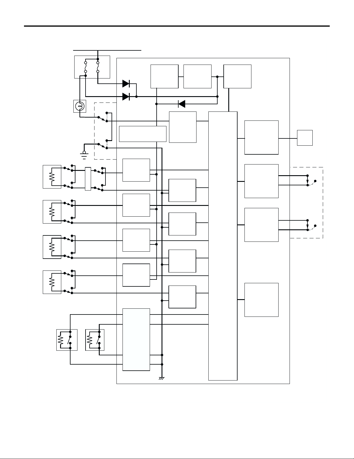
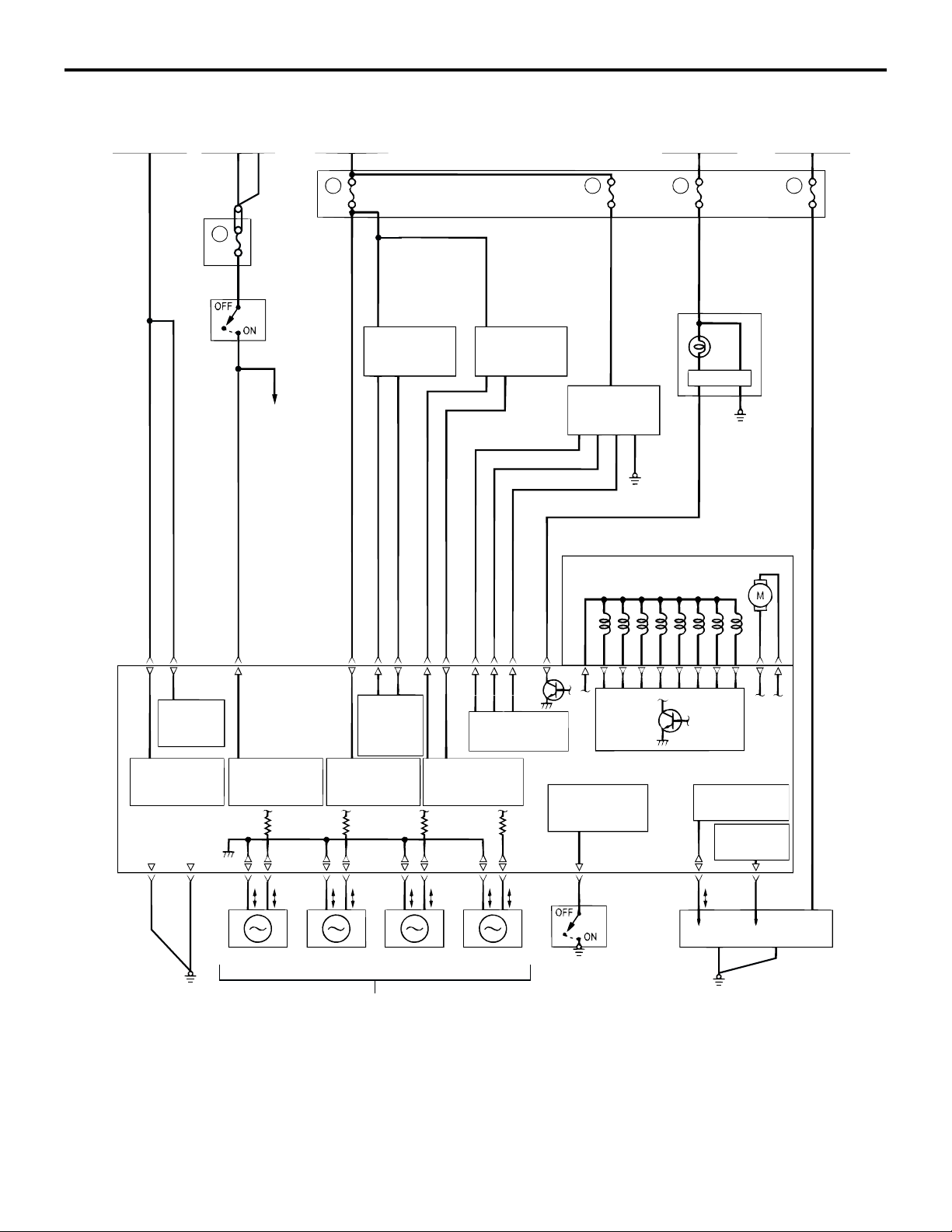
SRS SYSTEM CIRCUIT DIAGRAM
IGNITION SWITCH (IG1)
No.3
No.2
7.5A
7.5A
COMBINATION
METER (SRS
WARNING LIGHT)
CONNECTOR LOCK
SWITCH*
DRIVER'S
AIR BAG
MODULE
OFF
ON
OFF
PASSENGER'S
(FRONT) AIR BAG
MODULE
SEAT BELT
PRE-TENSIONER
(LH)
SEAT BELT
PRE-TENSIONER
(RH)
ON
OFF
ON
OFF
ON
OFF
ON
OFF
ON
OFF
ON
OFF
CONNCTOR LOCK
SWITCH*
CLOCK SPRING
CONNECTOR
LOCK SWITCH*
CONNECTOR
LOCK SWITCH*
CONNECTOR
LOCK SWITCH*
OFF
ON
OFF
ON
OFF
ON
OFF
ON
FRONT AIR BAG
SAFING
G-SENSOR
AIR BAG
DRIVE
CIRCUIT
AIR BAG
DRIVE
CIRCUIT
AIR BAG
DRIVE
CIRCUIT
AIR BAG
DRIVE
CIRCUIT
GENERAL DESCRIPTION
BACK UP
CAPACITOR
DC-DC
CONVERTER
WARNING
LIGHT
DRIVE
CIRCUIT
AIR BAG
DRIVE
CIRCUIT
AIR BAG
DRIVE
CIRCUIT
AIR BAG
DRIVE
CIRCUIT
AIR BAG
DRIVE
CIRCUIT
MICRO
PROCESSOR
POWER
SOURCE
CIRCUIT FOR
SIDE-AIRBAG
SCAN TOOL
INTERFACE
CIRCUIT
CONNECTOR
LOCK
DETECTION
CIRCUIT
CONNECTOR
LOCK
DETECTION
CIRCUIT
FRONT AIR
BAG
ANALOG
G-SENSOR
DATA LINK
CONNECTOR
(FOR SCAN
TOOL)
OFF
ON
OFF
ON
CONNECTOR
LOCK SWITCH*
(LH) (RH)
FRONT IMPACT
SENSOR
NOTE
*: CONNECTOR LOCKED: ON
CONNECTOR UNLOCKED: OFF
FRONT
IMPACT
SENSOR
INTERFACE
CIRCUIT
AC211582
AB
Page 6
SUPPLEMENTAL RESTRAINT SYSTEM (SRS)
GENERAL DESCRIPTION
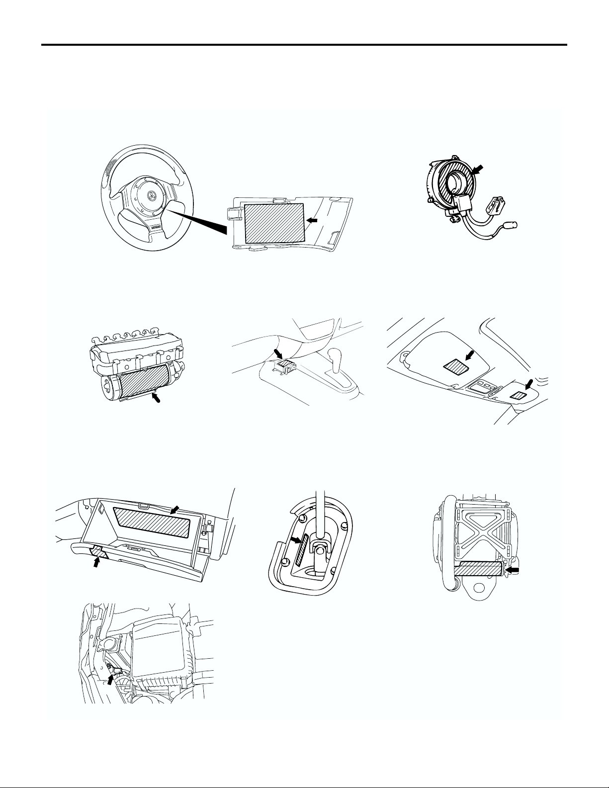
CAUTION LABELS
Labels to indicate cautions regarding the handling
and the services of SRS air bag air attached on the
position shown in the following illustration.
52B-5
PASSENGER'S (FRONT)
AIR BAG MODULE
C
COVER
D
A
SRS-ECU
CLOCK SPRING
B
SUN VISOR
E
E
GLOVE BOX
G
FRONT IMPACT SENSOR
J
SEAT BELT WITH
STEERING JOINT COVER
F
H
PRE-TENSIONER
(DRIVER'S AND FRONT
PASSENGER'S SEATBELT)
I
AC211604
AB
Page 7

52B-6
LABEL CONTENTS
AWARNING: SRS
BEFORE REPLACING STEERING WHEEL, READ SERVICE MANUAL. THIS AIR BAG
MODULE CANNOT BE REPAIRED.
DO NOT DISASSEMBLE OR TAMPER.
BCAUTION: SRS CLOCK SPRING
THIS IS NOT A REPAIRABLE PART. IF DEFECTIVE, REPLACE ENTIRE UNIT
ACCORDING TO THE SERVICE MANUAL INSTRUCTIONS. TO RE-CENTER: ROTATE
CLOCKWISE UNTIL TIGHT. THEN ROTATE IN OPPOSITE DIRECTION ROUGHLY 3
TURNS AND ALIGN ARROWS >><<.
CWARNING FLAMMABLE/EXPLOSIVE SRS AIR BAG MODULE
TO AVOID SERIOUS INJURY:
• DO NOT REPAIR, DISASSEMBLE OR TAMPER.
• AVOID C ONTA CT WIT H F LAM E OR ELECTRICITY.
• DO NOT DIAGNOSIS/USE NO TEST EQUIPMENT OR PROBES.
• STORE BELOW 200°F (93°C).
• BEFORE DOING ANY WORK INVOLVING MODULE, READ SERVICE MANUAL
FOR IMPORTANT FURTHER DATA.
DCAUTION:
DO NOT DISASSEMBLE OR DROP. IF DEFECT REFER TO SERVICE MANUAL.
SUPPLEMENTAL RESTRAINT SYSTEM (SRS)
GENERAL DESCRIPTION
EWARNING
DEATH or SERIOUS INJURY can occur
• Children 12 and under can be killed by the air bag.
• The BACK SEAT is the SAFEST place for children.
• NEVER put a rear-facing child seat in the front.
• Sit as far back as possible from the air bag.
• ALWAYS use SEAT BELTS and CHILD RESTRAINTS.
FAIR BAG SYSTEM INFORMATION
THIS VEHICLE HAS AN AIR BAG SYSTEM WHICH WILL SUPPLEMENT THE SEAT
BELT IN CERTAIN FRONTAL COLLISIONS. THE AIR BAG IS NOT A SUBSTITUTE FOR
THE SEAT BELT IN ANY TYPE OF COLLISION. THE DRIVER AND ALL OTHER
OCCUPANTS SHOULD WEAR SEAT BELTS AT ALL TIME.
WARNING!
IF THE "SRS" WARNING LIGHT DOES NOT ILLUMINATE FOR SEVERAL SECONDS
WHEN IGNITION KEY IS TURNED TO "ON" OR THE ENGINE IS STARTED, OR IF THE
WARNING LIGHT STAYS ON WHILE DRIVING, TAKE THE VEHICLE TO YOUR
NEAREST AUTHORIZED DEALER IMMEDIATELY. ALSO, IF VEHICLE'S FRONT END
IS DAMAGED OR IF THE AIR BAG HAS DEPLOYED, TAKE THE VEHICLE FOR
SERVICE IMMEDIATELY.
THE AIR BAG SYSTEM MUST BE INSPECTED BY AN AUTHORIZED DEALER TEN
YEARS AFTER THE VEHICLE MANUFACTURE DATE SHOWN ON THE
CERTIFICATION LABEL LOCATED ON THE LEFT FRONT DOOR-LATCH POST OR
DOOR FRAME.
READ THE "SRS" SECTION OF YOUR OWNER'S MANUAL BEFORE DRIVING FOR
IMPORTANT INFORMATION ABOUT OPERATION AND SERVICE OF THE AIR BAG
SYSTEM.
WHEN YOU ARE GOING TO DISCARD YOUR GAS GENERATOR OR VEHICLE,
PLEASE SEE YOUR DEALER.
Page 8
SUPPLEMENTAL RESTRAINT SYSTEM (SRS)
SYSTEM OPERATION
LABEL CONTENTS
GWARNING
CHILDREN CAN BE KILLED OR INJURED BY PASSENGER AIR BAG. THE BACK
SEAT IS THE SAFEST PLACE FOR CHILDREN 12 AND UNDER. MAKE SURE ALL
CHILDREN USE SEAT BELTS OR CHILD SEAT. NOT TO BE REMOVED EXCEPT BY
OWNER.
HCAUTION: SRS
FIX STRG. WHEEL AT TIRES STRAIGHT AHEAD BEFORE GEARBOX REMOVAL.
OTHERWISE, MAY DAMAGE SRS CLOCK SPRING MAKING SRS SYSTEM IN
OPERATIVE. RISKING SERIOUS DRIVER INJURY.
IDANGER SEAT BELT PRETENSIONER
CAUTION THIS ASSEMBLY CONTAINS AN EXPLOSIVE INITIATOR
FLAMMABLE MATERIAL
TO PREVENT PERSONAL INJURY
• DO NOT IMPACT, DISMANTLE OR INSTALL IT INTO ANOTHER VEHICLE.
• SERVICE OR DISPOSE OF IT AS DIRECTED IN THE REPAIR MANUAL.
JCAUTION:
DO NOT DISASSEMBLE OR DROP.
52B-7
SYSTEM OPERATION
A passengerís (front) air bag module and clock
spring are the same as OUTLANDER.
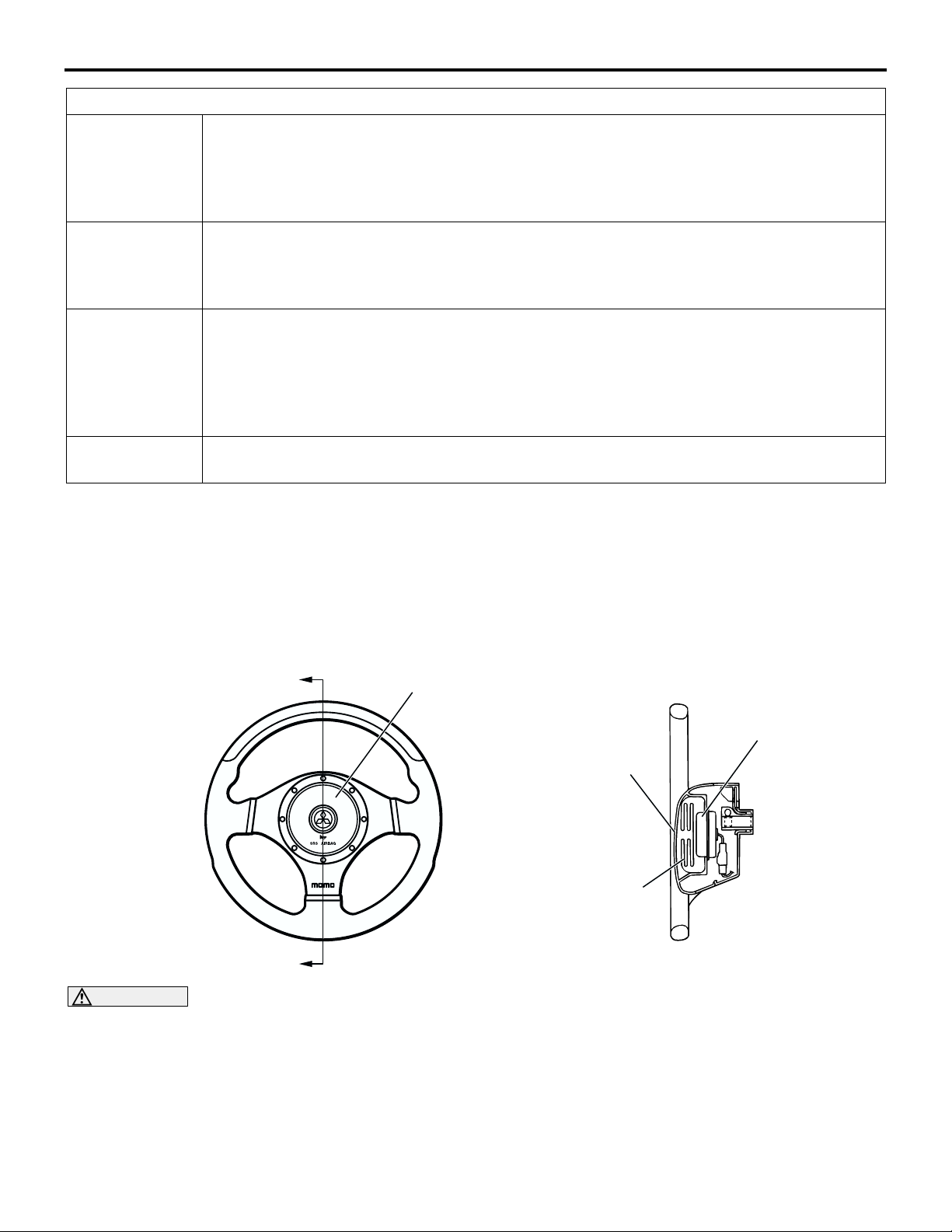
DRIVERíS AIR BAG MODULE
A
A
CAUTION
Never disassemble the air bag module.
The driverís air bag module is incorporated into the
3-spoke steering wheel. The driverís air bag module
is an assembly part consisting of air bag, module
cover, inflator, and its their fasteners. It is installed
into the steering wheel. The air bag is made from
AIR BAG MODULE
M2521001000116
SECTION A - A
INFLATOR
MODULE COVER
AIR BAG
AC211615
AB
nylon and inflates by the gas generating from the
inflator. As a driver is being pressed to the air bag, it
deflates discharging gas from two vents at the rear of
the air bag to reduce the shock from the impact. An
inflator that does not contain sodium azide is used.
Page 9
52B-8
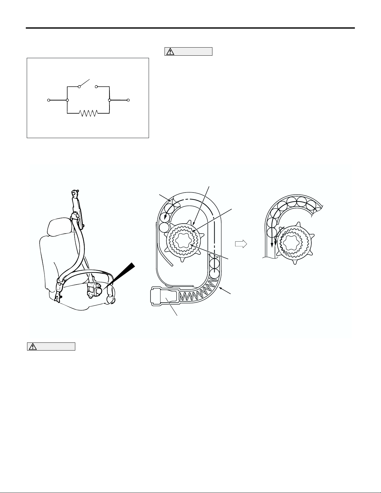
SENSOR INTERNAL CIRCUIT
SUPPLEMENTAL RESTRAINT SYSTEM (SRS)
SYSTEM OPERATION
FRONT IMPACT SENSOR
CAUTION
Never disassemble the front impact sensor.
The front impact sensor is installed in the radiator support
panel. In a collision, the contact in the front impact sensor turns
ON and an output signal is send to the SRS-ECU. A resistor is
connected to the front impact sensor in parallel with the contact
for fault diagnosis.
AC206958
AC
SEAT BELT WITH PRE-TENSIONER
BALL
RING GEAR
PINION
SPOOL
PIPE
GAS GENERANT
CAUTION
Never disassemble the seat belt with pre-tensioner.
The seatbelt incorporating the pretensioner automatically winds the seatbelt upon front impact to reduce
forward shifting of the passenger.
The seat belt pre-tensioner is built into the driver's
and passenger's front seat belt retractor.
AC101663
AE
Upon front impact the pretensioner ignites the gas
generator and emits gas with the SRS-ECU signal
when the front impact sensor, attached to the front of
the body, detects an impact that exceeds the permissible limit. The gas pressure shifts the ball in the pipe
and the balls comes in contact with the protrusion of
the ring gear, The ball is inserted in the ring gear and
then interlocked with the pinion. The ring gear rotation forces the pinion to turn the spool toward the belt
wind direction to wind the webbing.
Page 10
SUPPLEMENTAL RESTRAINT SYSTEM (SRS)
SYSTEM OPERATION
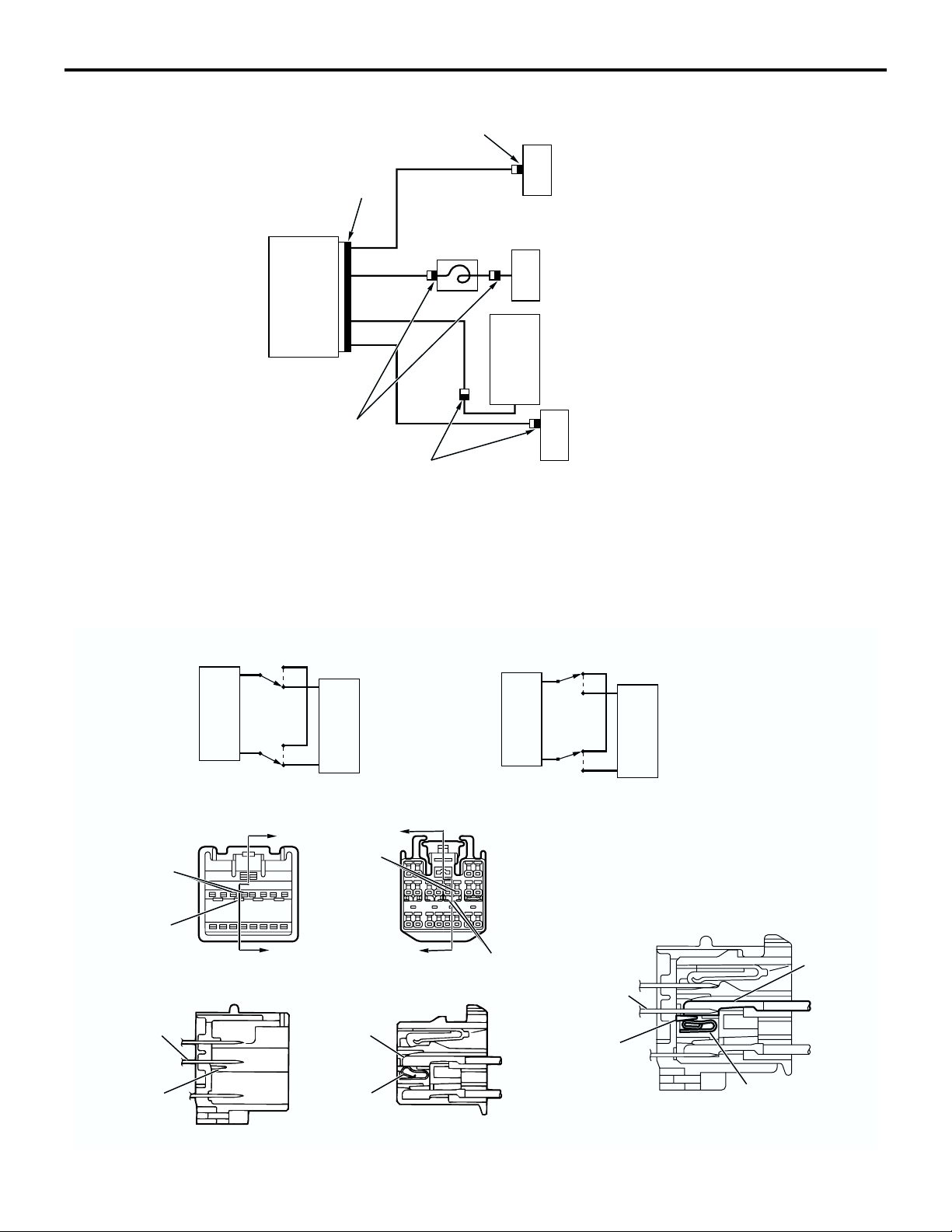
SRS AIR BAG SPECIAL CONNECTOR
A
CLOCK
SPRING
SRS-ECU
A
A
To en han ce th e Sys te mís r el iabi li ty, a c on nec to r lo ck
switch is integrated into the SRS-ECU connector, the
air bag module connectors, the clock spring connector, the seat belt pretensioner connectors (black connector "A" shown in the illustration above).
52B-9
A
SEAT BELT WITH
PRE-TENSIONER
(DRIVER'S SIDE)
DRIVER'S AIR BAG MODULE
PASSENGER'S (FRONT)
AIR BAG MODULE
SEAT BELT WITH
PRE-TENSIONER
(FRONT PASSENGER'S
SIDE)
AC103223
AF
SQUIB CIRCUIT CONNECTOR LOCK SWITCH
CONNECTOR CONNECTED
SQUIB
<CONNECTOR SHORTING MECHANISM (E.G. SRS-ECU CONNECTOR)>
ECU-SIDE CONNECTOR
TERMINAL
(MALE)
PARTITION
PANEL
SECTION A - A
TERMINAL
(MALE)
OFF
ON
OFF
ON
A
A
SRS-ECU
WIRING HARNESS-SIDE CONNECTOR
TERMINAL
(FEMALE)
TERMINAL
(FEMALE)
B
CONNECTOR DISCONNECTED
SQUIB
B
SECTION B - B
SHORT SPRING
OFF
ON
OFF
ON
TERMINAL
(MALE)
PARTITION
PANEL
SRS-ECU
CONNECTOR CONNECTED
TERMINAL
(FEMALE)
PARTITION
PANEL
SHORT
SPRING
SHORT SPRING
AC006197
AH
Page 11
52B-10
SUPPLEMENTAL RESTRAINT SYSTEM (SRS)
SRS-ECU
CAUTION
When the connector is disconnected, there will
be short circuit between the terminals. This is not
a fault.
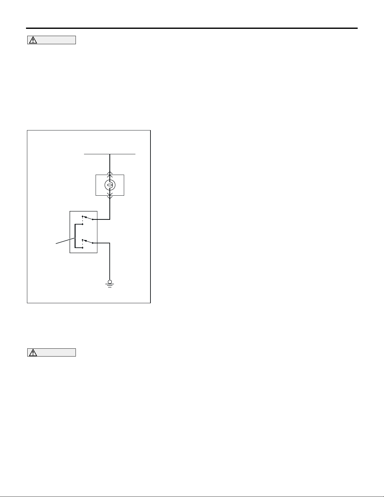
WARNING LIGHT CIRCUIT CONNECTOR LOCK
SWITCH
The switch is a mechanism that shorts the power supply termi-
IGNITION
SWITCH (IG1)
SRS WARNING
LIGHT
SRS-ECU HARNESS-SIDE
CONNECTOR
ON
nal to the ground terminal automatically in the warning light circuit, when the connector is disconnected. Its structure is similar
to the squib circuit connector shorting mechanism.
The switch is a mechanism that shorts the power
supply terminal to the ground terminal automatically
in the air bag squib circuit when the connector is disconnected. A "short" spring is integrated inside the
connector. This spring prevents static electricity from
flowing to the squib by shorting the power supply terminal to the ground terminal (i.e. there is no potential
difference between the two terminals).
CONNECTOR
LOCK SWITCH*
SHORT
SPRING
NOTE
*: CONNECTOR LOCKED: ON
CONNECTOR UNLOCKED: OFF
OFF
ON
OFF
AC006203
AB
SRS-ECU
CAUTION
Never disassemble the SRS-ECU.
The SRS-ECU incorporates an analog G-sensor and
safing G-sensor for frontal collisions and a safing Gsensor for side collisions. In frontal collisions, the
driverís and passengerís (front) air bags deploy and
the seat belt pre-tensioners are activated only when
both the analog and safing G-sensors detect simultaneously a collision-induced G of a level exceeding
the threshold as in the case with the conventional
system. In the case of side collisions, the side-airbag
on the side subjected to an impact deploys if the side
impact sensor and the SRS-ECUís safing G-sensor
detect simultaneously a lateral G of forces above the
predetermined level.
M2521007000095
The SRS-ECU is provided with the following capabilities:
• Backup power supply in case of power failure in
collisions
• Boosting function in case of battery voltage drop
• Self-diagnosis function to avoid systemís opera-
tion errors and improve its reliability
DIAGNOSTIC FUNCTION
The SRS-ECU has the following functions to make
system checking using the scan tool easy.
• Diagnostic trouble code output
• Service data output
Page 12

SUPPLEMENTAL RESTRAINT SYSTEM (SRS)
SRS-ECU
DIAGNOSTIC TROUBLE CODE OUTPUT
The SRS-ECU diagnoses the following items and
stores a diagnostic trouble code in the non-volatile
memory (EEPROM*
Therefore, the memory is not deleted after a battery
terminal is disconnected, (The diagnostic trouble
code memory can be deleted by the scan tool.)
CODE NO. MAJOR CONTENTS OF DIAGNOSTICS
1A Front impact sensor (LH) short-circuited
1B Front impact sensor (LH) open-circuited
1C Front impact sensor (LH) short-circuited to power supply
1D Front impact sensor (LH) short-circuited to ground
2A Front impact sensor (RH) short-circuited
2B Front impact sensor (RH) open-circuited
2C Front impact sensor (RH) short-circuited to power supply
2D Front impact sensor (RH) short-circuited to ground
14 Analog G-sensor malfunction
1
) when a problem is detected.
52B-11
15 Safing G-sensor short-circuited (for frontal collision)
16 Safing G-sensor open-circuited (for frontal collision)
21*
22*
24*
25*
26*
27*
28*
29*
3
3
3
3
3
3
3
3
Driver's air bag squib short-circuited
Driver's air bag squib open-circuited
Passenger's (front) air bag squib short-circuited
Passenger's (front) air bag squib open-circuited
Driver's pre-tensioner squib short-circuited
Driver's pre-tensioner squib open-circuited
Passenger's (front) pre-tensioner squib short-circuited
Passenger's (front) pre-tensioner squib open-circuited
31 SRS-ECU capacitor circuit voltage too high
32 SRS-ECU capacitor circuit voltage too low
34*
2
SRS-ECU connector lock out of order
35 Ignition of the air bag completed
39 Air bag deployed simultaneously
41*
42*
43*
44*
2
2
2
2
Power supply voltage (IG1 (A) voltage) drops a0bnormally.
Power supply voltage (IG1 (B) voltage) drops abnormally.
SRS warning light circuit open-circuited
SRS warning light circuit malfunction
45 SRS-ECU non-volatile memory (EEPROM) and A/D converter system
46*
2
Incorrect SRS-ECU
51 Driver's air bag squib activating circuit short-circuited
52 Driver's air bag squib activating circuit open-circuited
Page 13

52B-12
CODE NO. MAJOR CONTENTS OF DIAGNOSTICS
54 Passenger's (front) air bag squib activating circuit short-circuited
55 Passenger's (front) air bag squib activating circuit open-circuited
56 Driverís seat belt pre-tensioner (squib ignition drive circuit) system detected short
57 Driverís seat belt pre-tensioner (squib ignition drive circuit) system detected open
58 Passengerís seat belt pre-tensioner (squib ignition drive circuit) system detected
short
59 Passengerís seat belt pre-tensioner (squib ignition drive circuit) system detected
open
61 Driver's air bag squib drive circuit (power supply side) short-circuited
62 Driver's air bag squib drive circuit (ground side) short-circuited
64 Passenger's (front) air bag squib drive circuit (power supply side) short-circuited
65 Passenger's (front) air bag squib drive circuit (ground side) short-circuited
66 Driver's pre-tensioner squib (power supply side) short-circuited
67 Driver's pre-tensioner squib (ground side) short-circuited
68 Passenger's (front) pre-tensioner squib drive circuit (power supply side) short-
circuited
SUPPLEMENTAL RESTRAINT SYSTEM (SRS)
SRS-ECU
69 Passenger's (front) pre-tensioner squib drive circuit (ground side) short-circuited
NOTE: *1: Electrically Erasable Programmable ROM
2
: This diagnostic trouble code memory will be automatically cleared from the memory and the SRS warning
*
light will be switched off when the system returns to normal condition.
3
: The diagnostic trouble codes will remain in memory and the SRS warning light will be switched off if the
*
system returns to normal condition.
DATA LIST OUTPUT
When the SRS-ECU detects a problem, it stores a
diagnostic trouble code and the duration that the
problem has lasted in the non-voltage memory. In
addition, how often a diagnostic trouble code and
duration are cleared by the scan tool are stored in
the non-volatile memory as a reference for service
work. This data can be read by the scan tool.
No. DATA LIST ITEM APPLICABILITY
92 Number indicating how often the memory is cleared Maximum time to be stored: 250
days
93 How long a problem has lasted (How long from the
occurrence of the problem until the first air bag squib
ignition signal)
94 How long a problem has lasted (How long from the first
air bag squib igniting signal until now)
Maximum time to be stored: 9999
minutes (approximately seven
days)
Page 14

GROUP 36
PARKING BRAKE
CONTENTS
GENERAL INFORMATION . . . . . . . . 36-2
36-1
Page 15
36-2
PARK ING BR AKE
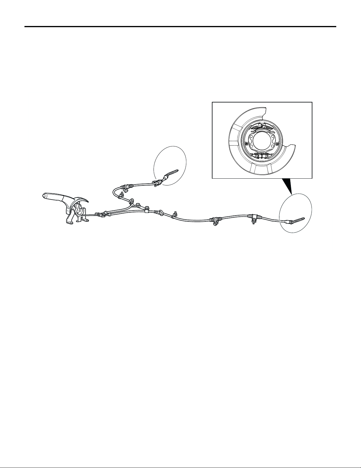
GENERAL INFORMATION
GENERAL INFORMATION
FEATURE
The parking brakes are a mechanical rear wheel
brake design and controlled by a lever.
CONSTRUCTION DIAGRAM
M2360000100173
AC211553
AB
Page 16

GROUP 35B
FOUR-WHEEL
ANTI-LOCK BRAKE
SYSTEM (4ABS)
CONTENTS
35B-1
GENERAL DESCRIPTION. . . . . . . . . 35B-2
SENSORS . . . . . . . . . . . . . . . . . . . . . 35B-6
ACTUATORS . . . . . . . . . . . . . . . . . . . 35B-8
BRAKE MODULATOR (ABS-ECU) . . 35B-9
SYSTEM OPERATION . . . . . . . . . . . . 35B-10
Page 17

35B-2
FOUR-WHEEL ANTI-LOCK BRAKE SYSTEM (4ABS)
GENERAL DESCRIPTION
GENERAL DESCRIPTION
Top comp on ents such as Bremb o! brakes, EBD and
sports ABS improve braking power and braking stability.
SPORTS ABS
• 4-wheel independent control optimizes the brake
force to each wheel to achieve a balance of
improved braking force and braking stability.
• A steering angular velocity sensor was added to
monitor the steering angle status. Braking force is
altered in response to the steering status to
improve the quality of steering when braking in
corners.
• The steering angular velocity sensor, lateral Gsensor and longitudinal G-sensor accurately
monitor driving conditions and optimize ABS control to match the specific driving conditions.
M2351000100186
EBD (Electronic Brake-force Distribution
system)
• Rear brake power is electronically controlled to
optimize performance in accordance with road
and load conditions and to ensure optimal distribution of braking force between the front and rear
brakes.
• Rear brake fluid pressure control employs a
brake modulator hydraulic unit solenoid valve that
made it possible to eliminate the pressure control
valves (proportioning valves).
• Effective use of rear wheel brake force reduces
temperature build-up in the front brakes under
hard braking conditions.
• Independent control of the left and right rear
brakes when braking during cornering achieves a
balance of improved vehicle stability and braking
force.
SPECIFICATIONS
ITEM LANCER EVOLUTION LANCER
ABS control method 4-sensor, 4-channel 4-sensor, 4-channel
No. of ABS rotor teeth Front 43 43
Rear 43 43
ABS sensor Type Magnet coil type Magnet coil type
Gap between sensor
and rotor mm (in)
Front 0.85 (0.033)
<Non-adjustable type>
Rear 0.60 (0.023)
<Non-adjustable type>
0.85 (0.033)
<Non-adjustable type>
0.89 (0.035)
<Non-adjustable type>
Page 18
FOUR-WHEEL ANTI-LOCK BRAKE SYSTEM (4ABS)
CONSTRUCTION DIAGRAM
GENERAL DESCRIPTION
6
4
35B-3
8
7, 10
9
AC209828
5
10067AU
2
3
1
1
AC211546
AB
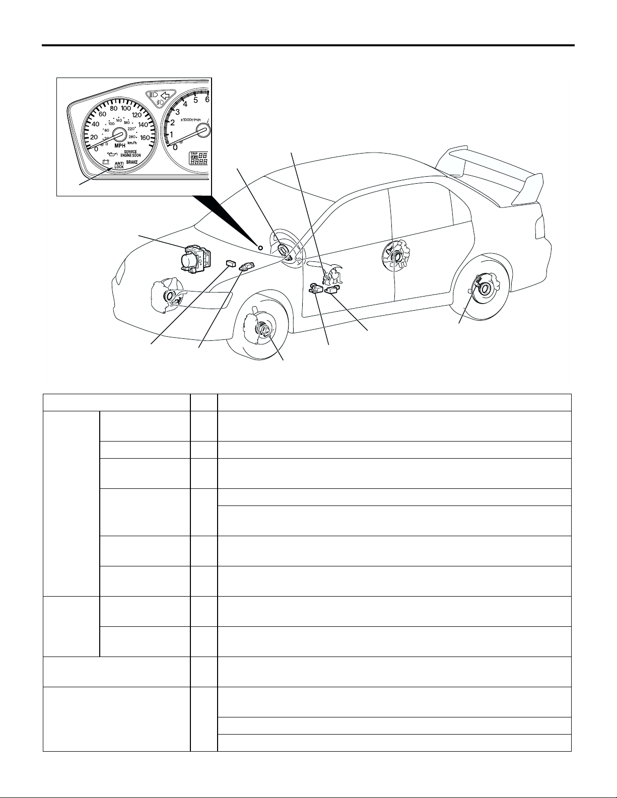
NAME OF PART NO. OUTLINE OF FUNCTION
Sensor ABS sensor 1 Sends alternating current signals at frequencies which are proportional
to the rotation speeds of each wheel to the ABS-ECU.
Lateral G-sensor 2 Sends data on vehicleís rate of lateral acceleration to the ABS-ECU.
Longitudinal Gsensor
Steering angular
velocity sensor
3Sends data on vehicleís rate of longitudinal acceleration to the ABS-
ECU.
4Sends data on steering wheel angle to the ABS-ECU.
Indicates the ABS-ECU when steering wheel is in straight-ahead
position.
Stoplight switch 5 Sends a signal to the ABS-ECU to indicate whether the brake pedal is
depressed or not.
Parking brake
switch
6Sends a signal to the ABS-ECU to indicate whether the parking brake
lever is pulled or not.
Actuator Hydraulic unit 7 Drives the solenoid valves according to signals from the ABS-ECU in
order to control the brake hydraulic pressure for each wheel.
ABS warning
light
8Illuminates in response to signals from the ABS-ECU when a problem
develops in the system.
Data link connector 9 Outputs the diagnostic trouble codes and allows communication with
the scan tool.
Brake modulator (ABS-ECU) 10 Controls actuators (described above) based on the signals coming from
each sensor.
Controls the self-diagnosis and fail-safe functions.
Controls the diagnostic function (scan tool compatible).
Page 19
35B-4
FOUR-WHEEL ANTI-LOCK BRAKE SYSTEM (4ABS)
GENERAL DESCRIPTION
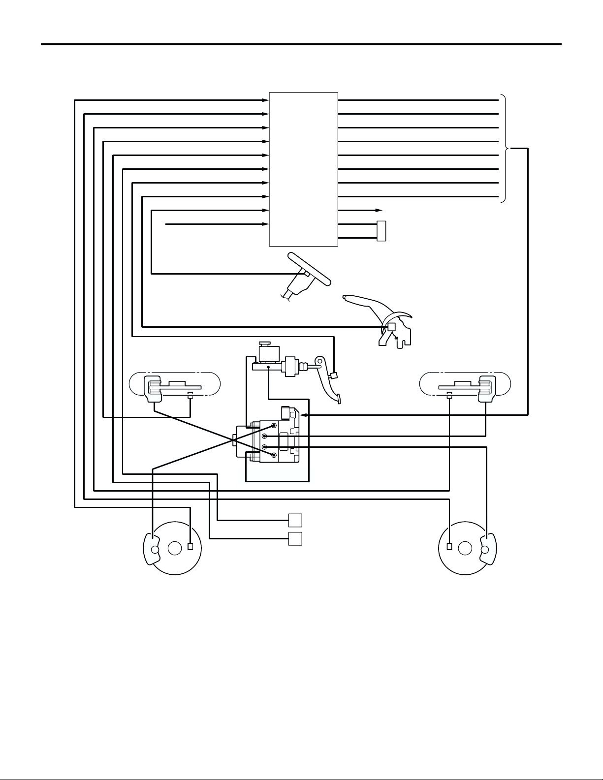
SYSTEM CONFIGURATION DIAGRAM
ABS SENSOR (FL)
ABS SENSOR (RL)
ABS SENSOR (RR)
ABS SENSOR (FR)
LONGITUDINAL G-SENSOR
LATERAL G-SENSOR
STOPLIGHT SWITCH
PARKING BRAKE SWITCH
STEERING ANGULAR VELOCITY SENSOR
ECU POWER SUPPLY
FRONT-RIGHT
WHEEL (FR)
ABS-ECU
FR SOLENOID VALVE (OUT)
FR SOLENOID VALVE (IN)
FL SOLENOID VALVE (OUT)
FL SOLENOID VALVE (IN)
RR SOLENOID VALVE (OUT)
RR SOLENOID VALVE (IN)
RL SOLENOID VALVE (OUT)
RL SOLENOID VALVE (IN)
ABS WARNING LIGHT
DATA LINK CONNECTOR
STEERING ANGULAR
VELOCITY SENSOR
PARKING
BRAKE
SWITCH
STOPLIGHT
SWITCH
REAR-RIGHT
WHEEL (RR)
FRONT-LEFT
WHEEL (FL)
ABS
SENSOR
ABS SENSOR
HYDRAULIC
UNIT
ABS SENSOR
LATERAL G-SENSOR
LONGITUDINAL G-SENSOR
ABS SENSOR
REAR-LEFT
WHEEL (RL)
10066AU
AC211547
AB
Page 20
FOUR-WHEEL ANTI-LOCK BRAKE SYSTEM (4ABS)
GENERAL DESCRIPTION
ABS ELECTRICAL CIRCUIT DIAGRAM
35B-5
FUSIBLE
LINK 3 BATTERY
10
15A
STOPLIGHT
IGNITION
SWITCH (IG2)
RELAY
BOX
STOPLIGHT
SWITCH
12
7.5A
LATERAL
G-SENSOR
JUNCTION BLOCK
LONGITUDINAL
G-SENSOR
IGNITION
SWITCH (IG1)
5
7.5A
STEERING
ANGULAR
VELOCITY
SENSOR
HYDRAULIC UNIT
SOLENOID VALVE
2
7.5A
COMBINATION
METER
ANTI
LOCK
MOTOR
FUSIBLE
LINK 1
15
15
15A
15A
ABS-ECU
MOTOR
POWER
SUPPLY
SOLENOID
VALVE POWER
SUPPLY
LATERAL
G-SENSOR
INPUT
STOPLIGHT
SWITCH
MONITOR
FL FR RL RR
(FL) (FR) (RL) (RR)
ECU
POWER
SUPPLY
STEERING ANGULAR
VELOCITY SENSOR
INPUT
ABS SENSOR
LATERAL
G-SENSOR
INPUT
PARKING BRAKE
SWITCH MONITOR
PARKING
BRAKE
SWITCH
COMMUNICATION
LINE
CONTROL
LINE
DATA LINK
CONNECTOR
AC211548
AB
Page 21
35B-6
FOUR-WHEEL ANTI-LOCK BRAKE SYSTEM (4ABS)
SENSORS
SENSORS
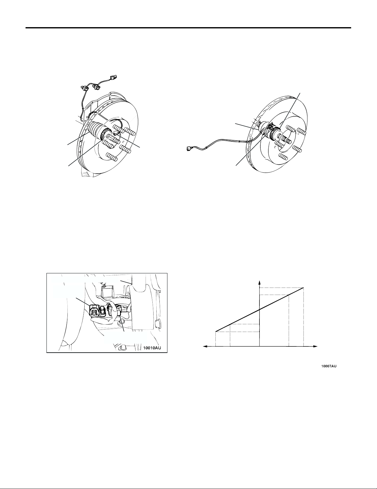
ABS SENSOR
FRONT
DRIVESHAFT
ABS SPEED
SENSOR
ABS ROTOR
The ABS sensors consist of fixed ABS speed sensors and the ABS rotors that rotate at the same
speed as the wheels, that output alternating current
signals at frequencies which are proportional to the
wheel speed.
M2351001000137
REAR
ABS ROTOR
DRIVESHAFT
ABS SPEED
SENSOR
AC211549
AB
• The ABS rotors (43 teeth) are installed to the
drive shafts, and the ABS speed sensors are
installed to knuckles.
• The gap between the ABS rotors and the ABS
speed sensors are non-adjustable at both the
front and rear to improve serviceability.
LATERAL G-SENSOR/LONGITUDINAL G-SENSOR
G-SENSOR OUTPUT CHARACTERISTICS
PARKING BRAKE LEVER
LATERAL
G-SENSOR
LONGITUDINAL
G-SENSOR
ACCELERATION
SPEED (G)
The longitudinal G-sensor detects the acceleration in
the lateral direction of the vehicle, and are basically
the same as those used conventionally. The lateral
G-sensor is used for detecting the acceleration along
the sides of the vehicle by changing the installing
direction by 90 degree angle. The same sensor as
the longitudinal G-sensor is used.
OUTPUT VOLTAGE (V)
4.0
3.5
2.5
1.5
1.0
0 1.01.0 1.51.5
DECELERATION
SPEED (G)
AC211550
AB
Page 22
FOUR-WHEEL ANTI-LOCK BRAKE SYSTEM (4ABS)
SENSORS
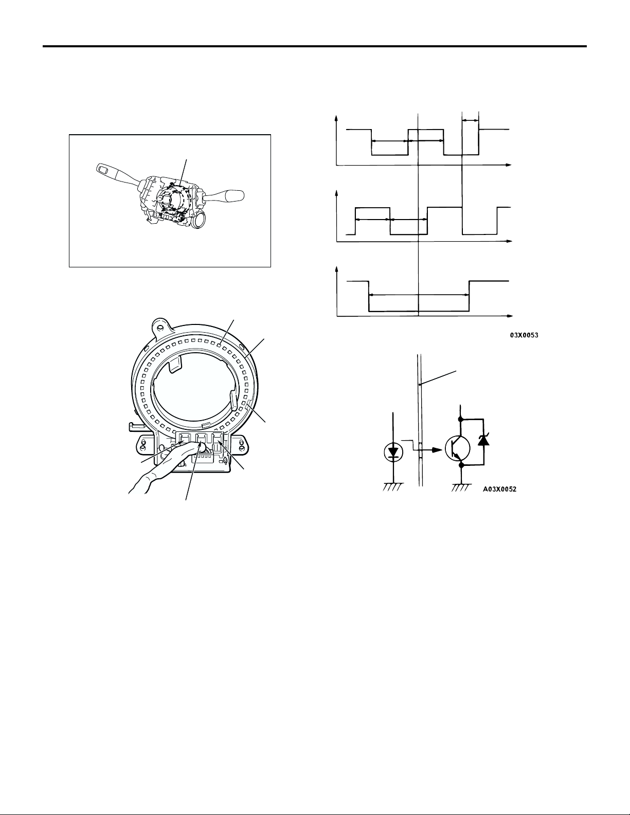
STEERING ANGULAR VELOCITY SENSOR
35B-7
OUTPUT WAVEFORM OF EACH PHOTOINTERRUPTOR
STEERING ANGULAR
VELOCITY SENSOR
Y2057AU
SLIT
SLIT PLATE
ST-1
ST-2
ST-N
V
HLHLH
L
V
H
L
V
H
L
4˚ 4˚4˚ 4˚
4˚ 4˚
11˚
2˚
θ
θθ
θ
SLIT PLATE
NEUTRAL POSITION
DETECTION SLIT
PHOTOINTERRUPTOR
(ST-2)
PHOTOINTERRUPTOR
(ST-1)
PHOTOINTERRUPTOR
(ST-N)
10091AU
The steering angular velocity sensor is installed at
the steering column, and is used to output steer
angles to the ABS-ECU as signals. It is composed of
the slit plate which rotates according to the movements of the steering wheel and a three-set photointerruptor. The slit plate and photointerruptors have a
sealed integrated structure to prevent the invasion of
foreign particles as well as misoperations by external
light. To detect malfunctions of the sensor output circuit, it is equipped with a zener diode for detecting
disconnections parallel to the photo-transistor. The
ZENER DIODE (FOR
DISCONNECTION
DETECTION)
LIGHT-EMITTING
DIODE
PHOTO-TRANSISTOR
AC211551
AB
ABS-ECU calculates the steering angle by reading
the signals of the steering angular velocity sensor
after every certain period of time and calculating the
total of the ST-1 signal and ST-2 signal. The steering
angle is obtained by taking the neutral position (ST-N
output is L center) as 0 degree angle, and if there are
changes, the steering angle is added with 2 degree
angle for right and -2 degree angle for left. The output of the photointerruptor becomes L (low) when
light passes through and H (high) when obstructed.
Page 23
35B-8
FOUR-WHEEL ANTI-LOCK BRAKE SYSTEM (4ABS)
ACTUATORS
STOPLIGHT SWITCH
This switch turns on when the brake pedal is
depressed, and turns off when the brake pedal is
released. The ABS-ECU detects whether the stoplight switch is on or off by means of fluctuations in
voltage (ON: system voltage; OFF: Approximately 0
V). This data is used for ABS control.
ACTUATORS
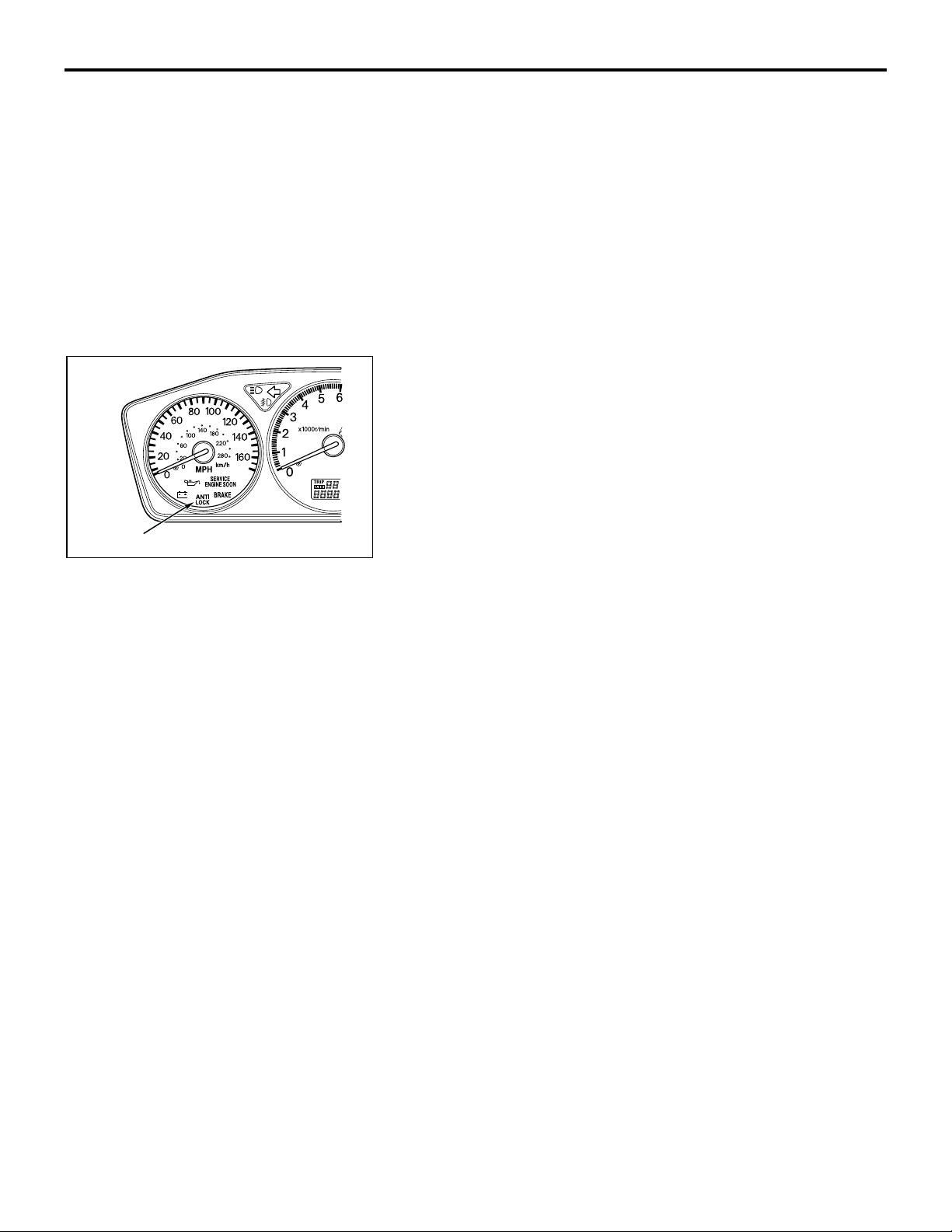
ABS WARNING LIGHT
The ABS-ECU controls the power transistor in ABS-ECU to
turn on and causes the ABS warning light to illuminate in the
following cases:
• During initial check when the ignition switch is at the "ON"
position (for approximately three seconds)
• When a problem develops in the ABS/EBD system
• Poor ABS-ECU connector connection
ABS WARNING LIGHT
AC211552
AB
PARKING BRAKE SWITCH
This switch turns on when the parking brake lever is
pulled, and turns off when the parking brake lever is
released. The ABS-ECU detects whether the parking
brake switch is on or off by means of fluctuations in
voltage (ON: less than 1 volt; OFF: system voltage).
This data is used for ABS control.
M2351002000099
HYDRAULIC UNIT
The hydraulic unit is basically the same as that of the LANCER.
Page 24

FOUR-WHEEL ANTI-LOCK BRAKE SYSTEM (4ABS)
BRAKE MODULATOR (ABS-ECU)
35B-9
BRAKE MODULATOR (ABS-ECU)
The ABS-ECU is basically the same as that of the
LANCER except the followings:
DIAGNOSTIC FUNCTIONS
.
DIAGNOSTIC TROUBLE CODE OUTPUT
DTC ITEM
11 Ope n cir cuit or shor t-ci rcuit in ABS senso r (F R)
12 Open circuit or short-circuit in ABS sensor (FL)
13 Open circuit or short-circuit in ABS sensor (RR)
14 Open circuit or short-circuit in ABS sensor (RL)
16 Abnormal drop or rise in ABS-ECU power supply voltage
21 ABS sensor (FR) system
22 ABS sensor (FL) system
23 ABS sensor (RR) system
24 ABS sensor (RL) system
32 Longitudinal G-sensor system
41 Solenoid valve (FR) system
M2351003000144
42 Solenoid valve (FL) system
43 Solenoid valve (RR) system
44 Solenoid valve (RL) system
51 Valve relay ON problem
52 Valve relay OFF problem
53 Motor relay OFF problem
54 Motor relay ON problem
55 Motor system
63 ABS-ECU abnormality
71 Lateral G-sensor system
81 Steering angular velocity sensor (ST-1) system
82 Steering angular velocity sensor (ST-2) system
83 Steering angular velocity sensor (ST-N) system
.
Page 25

35B-10
FOUR-WHEEL ANTI-LOCK BRAKE SYSTEM (4ABS)
SYSTEM OPERATION
SERVICE DATA OUTPUT
SCAN TOOL
DISPLAY
ITEM NO. CHECK ITEM DISPLAY TEXT
OR UNIT
FR SNSR 11 Front-right ABS sensor km/h or mph
FL SNSR 12 Front-left ABS sensor
RR SNSR 13 Rear-right ABS sensor
RL SNSR 14 Rear-left ABS sensor
BATT. VOLTAGE 21 ABS-ECU power supply voltage V
29 Parking brake switch ON/OFF
32 Longitudinal G-sensor V
STOPLIGHT SW 36 Stoplight switch ON/OFF
37 Steering angular velocity sensor straight ahead position
ON/OFF
memory
71 Lateral G-sensor V
74 Steering angular velocity sensor (ST-N) OFF/ON
75 Steering angular velocity sensor (ST-1)
76 Steering angular velocity sensor (ST-2)
86 Steering angle
° or OFF (when the
steering angle is
straight ahead
position)
.
ACTUATOR TEST
NO. ITEM PARTS TO BE ACTIVATED
01 Solenoid valve for front-left wheel Solenoid valves and pump motors in the hydraulic
02 Solenoid valve for front-right wheel
unit (simple inspection mode)
03 Solenoid valve for rear-left wheel
04 Solenoid valve for rear-right wheel
SYSTEM OPERATION
In terms of operation, the system is basically the
same as that of the LANCER.
M2351004000114
Page 26

GROUP 35
SERVICE BRAKES
CONTENTS
SERVICE BRAKES . . . . . . . . . . . . . . . . . . . . . . . . . . . . . . . . . . . 35A
FOUR-WHEEL ANTI-LOCK BRAKE SYSTEM (4ABS) . . . . . . . 35B
35-1
Page 27

NOTES
Page 28

GROUP 35A
SERVICE BRAKES
CONTENTS
35A-1
GENERAL DESCRIPTION. . . . . . . . . 35A-2
MASTER CYLINDER . . . . . . . . . . . . . 35A-4
BRAKE BOOSTER ASSEMBLY . . . . 35A-4
FRONT DISC BRAKE. . . . . . . . . . . . . 35A-5
REAR DISC BRAKE . . . . . . . . . . . . . . 35A-6
Page 29
35A-2
SERVICE BRAKES
GENERAL DESCRIPTION
GENERAL DESCRIPTION
Top comp on ents such as Bremb o! brakes, EBD and
sports ABS improve braking power and braking stability.
FEATURES
.
Improved braking performance
1. A 8+9-inch tandem vacuum booster is utilized to
provide high braking force with a small pedal
depression force.
2. Brembo! 17-inch 4-pot front ventilated disc
brakes and Brembo! 16-inch 2-pot rear ventilated disc brakes are adopted to provide stable
braking force and improved braking feel.
.
Improved stability
1. Sports ABS (4-wheel anti-lock braking system) is
used to prevent slipping caused by the vehicle
wheels locking up in order to maintain an appropriate braking distance, and also to maintain a
stable vehicle posture and steering performance.
M2350000100183
2. Adoption of an electronic brake-force distribution
(EBD) makes it possible to maintain the maximum amount of braking force even when the
vehicle's load is unevenly distributed.
3. Front- and rear-wheel X-type brake line layout is
used.
4. Ventilated discs improve anti-fading performance.
.
Improved serviceability
1. A diagnosis function has been adopted for the
ABS system in order to make inspection easier.
2. An outer disc method separated hub and rotor is
featured to make removal and installation easier.
3. The master cylinder reservoir tank cap is colored
white to make identification easier.
4. The ABS-ECU and hydraulic unit are integrated
to make them more compact and light weight.
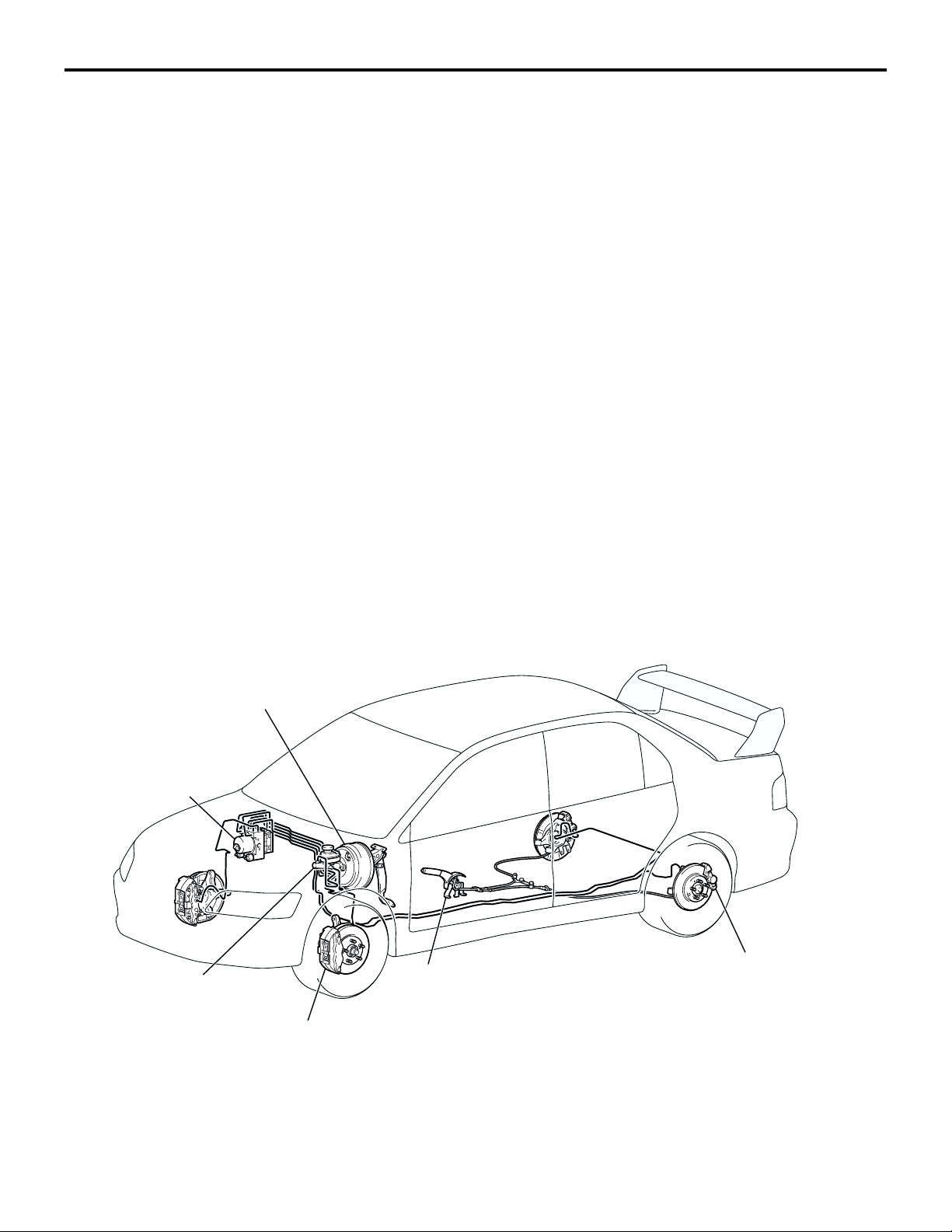
CONSTRUCTION DIAGRAM
BRAKE BOOSTER
ASSEMBLY
BRAKE MODULATOR
HYDRAULIC UNIT
(INTEGRATED WITH
THE ABS-ECU)
BRAKE MASTER
CYLINDER ASSEMBLY
FRONT DISC BRAKE
PARKING BRAKE
LEVER ASSEMBLY
10064AU
REAR DISC BRAKE
AC211387
AB
Page 30

SERVICE BRAKES
GENERAL DESCRIPTION
SPECIFICATIONS
ITEM SPECIFICATION
Master
cylinder
Type Tandem type
I.D. mm (in) 26.9 (1.06)
35A-3
Brake
booster
Rear wheel hydraulic control method Electronic brake-force distribution (EBD)
Front brakes Type 4-opposed piston, ventilated disc
Rear brakes Type 2-opposed piston, ventilated disc
Brake fluid DOT3 or DOT4
Type Vacuum type, tandem
Effective dia. of power cylinder
mm (in)
Boosting ratio 4.5 <Brake pedal depressing force: 230 N (51.7 lb)>
Disc effective dia × thickness
mm (in)
Wheel cylinder I.D. mm (in) 40.0 (1.58) × 2, 46.0 (1.81) × 2
Pad thickness mm (in) 10.0 (0.39)
Clearance adjustment Automatic
Disc effective dia × thickness
mm (in)
Wheel cylinder I.D. mm (in) 40.0 (1.58) × 2
Pad thickness mm (in) 9.0 (0.35)
Clearance adjustment Automatic
205 + 230 (8.07 + 9.06)
263 × 32 (10.4 × 1.3)
252 × 22 (9.9 × 0.9)
Page 31

35A-4
SERVICE BRAKES
MASTER CYLINDER
MASTER CYLINDER
MASTER CYLINDER BODY
SECONDARY PISTON ASSEMBLY
The master cylinder is a tandem-type, with a structure that emphasizes safety.
BRAKE FLUID RESERVOIR
PRIMARY PISTON ASSEMBLY
PISTON RETAINER
AE
AC005372
M2350001000145
BRAKE BOOSTER ASSEMBLY
FRONT DIAPHRAGM
PUSH ROD
DIAPHRAGM RETURN SPRING
A 8 + 9-inch tandem-type brake booster assembly
has been adopted.
REAR DIAPHRAGM
OPERATING ROD
ATMOSPHERIC CHAMBERS
M2350002000148
AC206215
AC
Page 32

SERVICE BRAKES
FRONT DISC BRAKE
35A-5
FRONT DISC BRAKE
FRONT OF VEHICLE
Brakes with the following specifications have been
adopted for the front brakes.
• Brembo! V7-Z4046 4-opposed-piston ventilated
discs
• An outer disc method in which the wheels and
discs are tightened together is used to improve
the ease of brake disc removal and installation.
DISC BRAKE NOMENCLATURE
M2350003000141
PADS
AC211388
AB
• The brake pads are equipped with mechanicaltype audible wear indicators to notify the driver
when the usage limit [2 mm (0.08 in)] is reached.
• Split fins adopted as the disc fins to improve cooling performance
NOTE: Brembo! is an italian brake component
maker whose name and products are well known in
the motorsports world.
V 7 – Z 40 46
2
1
34
AC211390
NO. ITEM CONTENT
1Brake disc type V: Ventilated
2Brake size
7: 17-inch
(Minimum applicable
disc wheel)
3No. of pistons Z: 4-piston (opposed
type)
4Piston size (rounded
to nearest integer)
40: φ40 mm (1.6 in)
46: φ46 mm (1.8 in)
Page 33

35A-6
SERVICE BRAKES
REAR DISC BRAKE
REAR DISC BRAKE
FRONT OF
VEHICLE
Brakes with the following specifications have been
adopted for the rear brakes.
• Brembo! V6-X40 2-opposed-piston ventilated
discs
• An outer disc method in which the wheels and
discs are tightened together is used to improve
the ease of brake disc removal and installation.
DISC BRAKE NOMENCLATURE
M2350004000155
PADS
AC211389
AB
• The brake pads are equipped with mechanicaltype audible wear indicators to notify the driver
when the usage limit [2 mm (0.08 in)] is reached.
• Split fins adopted as the disc fins to improve cooling performance
NOTE: Brembo! is an italian brake component
maker whose name and products are well known in
the motorsports world.
V6– X 40
2
1
34
AC211391
NO. ITEM CONTENT
1Brake disc type V: Ventilated
2Brake size
6: 16-inch
(Minimum applicable
disc wheel)
3No. of pistons X: 2-piston (opposed
type)
4Piston size (rounded
40: φ40 mm (1.6 in)
to nearest integer)
Page 34

GROUP 34
REAR SUSPENSION
CONTENTS
GENERAL DESCRIPTION. . . . . . . . . 34-2
34-1
Page 35

34-2
REAR SUSPENSION
GENERAL DESCRIPTION
GENERAL DESCRIPTION
A trailing arm type multi-link suspension is used for
the rear suspension. In contrast to the trailing arm
multi-link system used on the Lancer, the Lancer
Evolution uses a newly developed multi-link system
built on a double wishbone base to achieve superior
handling stability. Optimum design of the suspension
points and use of aluminum parts for the suspension
arms and crossmember reduces weight. In addition,
use of ball joints on the suspension arms reduce friction and creates a suspension system that exhibits
superior stroke characteristics that respond well
under all driving conditions.
STRUCTURE
1. The A-shape upper arm assembly mounted
inside the wheel combines with the three Ishaped arms including the trailing arm assembly
that runs in front-rear orientation with the vehicleís body, the lower arm assembly and the assist
link to support the knuckle.
2. Each arm uses a ball joint and pillow ball bushing
at the knuckle end and a pillow ball bushing at the
body end, and are mounted on the body via the
crossmember.
3. Alignment and suspension stroke, a wider track,
and optimization of roll center height improves
cornering response throughout the range from
initial response through to the cornering limit.
M2340000100137
COMPONENT CHARACTERISTICS
(COMPARED TO THE LANCER)
1. Suspension arm (made of forged aluminum)
• The trailing arm assembly, upper arm assembly, lower arm assembly and assist link are
made of forged aluminum to reduce weight
and increase rigidity.
• The knuckle mount and body-end mount for
the lower arm assembly use pillow ball bushings for high rigidity and reduce suspension
friction.
• The body-end mount for the assist link uses a
low-friction slide bushing.
2. Crossmember (made of forged aluminum)
• The crossmember is made of forged aluminum to reduce weight and increase rigidity.
3. Shock absorber, coil spring, stabilizer, bump rubber
• The shock absorber size was changed and
the rod diameter was increased to improve
stability during roll by increasing damping
response.
• Optimization of shock absorber damping,
spring rate, bump rubber characteristics and
bushing characteristics improves cornering
response throughout the range from initial
response through to the cornering limit.
Page 36

CONSTRUCTION DIAGRAM
COIL SPRING
REAR SUSPENSION
GENERAL DESCRIPTION
34-3
SHOCK ABSORBER
UPPER ARM ASSEMBLY
(FORGED ALUMINUM)
STABILIZER BAR LINK
ASSIST LINK
(FORGED ALUMINUM)
TRAILING ARM ASSEMBLY
(FORGED ALUMINUM)
ASSIST LINK
CONTROL BAR
CROSSMEMBER
(FORGED ALUMINUM)
DIFFERENTIAL SUPPORT
MEMBER
LOWER ARM ASSEMBLY
(FORGED ALUMINUM)
STABILIZER BAR
DIFFERENTIAL
SUPPORT ARM
AC211385
AB
SPECIFICATIONS
.
SUSPENSION SYSTEM
ITEM SPECIFICATION
Suspension method Trailing arm type multi-link
.
WHEEL ALIGNMENT
ITEM LANCER EVOLUTION LANCER
Camber
Toe -i n m m (in ) 3 (0 .12 ) 3 (0 .12 )
.
COIL SPRING
ITEM LANCER EVOLUTION LANCER
Wire diameter mm (in) 12 (0.5) 10 (0.4)
Average diameter mm (in) 88 (3.5) 90 (3.5)
Free length mm (in) 287 (11.3) 370 (14.6)
−1°00' −0°40'
Page 37

NOTES
Page 38

GROUP 33A
FRONT
SUSPENSION
CONTENTS
33A-1
GENERAL DESCRIPTION. . . . . . . . . 33A-2
LOWER ARM . . . . . . . . . . . . . . . . . . . 33A-4
STRUT ASSEMBLY . . . . . . . . . . . . . . 33A-5
Page 39

33A-2
FRONT SUSPENSION
GENERAL DESCRIPTION
GENERAL DESCRIPTION
A MacPherson strut independent suspension-type
suspension is used for the front suspension. Aggressive use of special components that include
Mitsubishi Motorís own inverted struts and forged
aluminum parts reduces weight to create a suspension that gives superior performance made with competition use in mind.
FEATURES (COMPARED TO THE
LANCER)
.
Inverted struts
Use of inverted struts ensures smooth shock
absorber action even during high speed cornering
that places high lateral G-force on the suspension.
.
Coil springs
The coil spring rate was optimized and highresponse spring material is used to achieve high
durability and reduce weight.
.
Lower arm assembly
Use of forged aluminum reduces load on the coil
springs and produces nimble suspension action. In
addition, outer casings and stoppers on the front
bushings (A-point) and pillow ball bushings in the
rear (G-point) improves the feeling of stiffness and
stroke. Increased size of the ball on the ball joints at
the knuckle connection (B-point) also improve reliability.
M2330000100147
.
Stabilizer
A change to pillow ball joints for the stabilizer link
improves stabilizer efficiency to deliver a high level of
stability.
.
Crossmember
A reinforcing bar (front axle crossmember bar) that
connects the left and right lower arm mounts (Apoints) increases lateral rigidity. This improves steering feel and adds extra stiffness when cornering.
.
Strut insulator
Input from the strut has been changed from a separation pattern to a unified one and the use of a metal
bearing achieves greater rigidity, durability, and lower
friction.
.
Alignment
A wider track and optimization of roll center height
improves cornering response throughout the range
from initial response through to the cornering limit.
Page 40

CONSTRUCTION DIAGRAM
STABILIZER LINK
(PILLOW BALL JOINT)
B-POINT
FRONT SUSPENSION
GENERAL DESCRIPTION
COIL SPRING
STABILIZER BAR
LOWER ARM BUSHING
(PILLOW BALL BUSHING)
33A-3
STRUT INSULATOR
STRUT
(INVERTED STRUT)
G-POINT
A-POINT
LOWER ARM ASSEMBLY
(FORGED ALUMINUM)
FRONT AXLE No.1
CROSSMEMBER
A-POINT
FRONT AXLE
CROSSMEMBER BAR
SPECIFICATIONS
.
SUSPENSION SYSTEM
ITEM SPECIFICATION
Suspension method MacPherson strut with coil springs
.
WHEEL ALIGNMENT
ITEM LANCER EVOLUTION LANCER
Camber -1°00' <Default factory setting>
(-2°00' adjustment possible)
Caster 3°55' 2°50'
Kingpin inclination 13°45' 12°35'
0°00'
AC211383
AB
Toe -i n m m (in ) 0 (0 ) 1 (0 .04 )
.
COIL SPRING
ITEM LANCER EVOLUTION LANCER (SPORT)
Wire diameter mm (in) 14 (0.6) 14 (0.6)
Average diameter mm (in) 155 (6.1) 160 (6.3)
Free length mm (in) 286 (11.3) 363 (14.3)
Page 41

33A-4
FRONT SUSPENSION
LOWER ARM
STOPPERS
FRONT OF VEHICLE
LOWER ARM
M2330002000050
LOWER ARM ASSEMBLY
PILLOW BALL BUSHING
ENLARGED BALL DIAMETER
Use of forged aluminum reduces load on the coil
springs and produces nimble suspension action. In
addition, outer casings and stoppers on the front
bushings and pillow ball bushings in the rear
improves the feeling of stiffness and stroke.
Increased size of the ball on the ball joints at the
knuckle connection also improve reliability.
AC211384
AB
Page 42

FRONT SUSPENSION
STRUT ASSEMBLY
33A-5
FRONT OF
VEHICLE
A
-1˚ CAMBER
SELECTED
STRUT ASSEMBLY
INVERTED
STRUT
KNUCKLE
ECCENTRIC BOLT
-1˚ CAMBER
SELECTED
A
-2˚ CAMBER
SELECTED
M2330001000079
SECTION A -A
-2˚ CAMBER
SELECTED
An inverted strut layout (with the cylinder at the top
and the piston at the bottom) is used. This layout
offers superior rigidity and consequently improved
camber stiffness. Further, either of two camber
angles can be selected in accordance with operating
conditions. The camber angle is determined by the
alignment of an eccentric bolt at the top of the joint
AC211392
AB
between the strut assembly and knuckle. Vehicles
leave the factory with a camber angle of -1 degree
angle selected. (An arrow on the eccentric bolt is
pointing toward the inside of the vehicle.) For a camber angle of -2 degree angle, the bolt must be positioned with its arrow pointing toward the outside of
the vehicle.
Page 43

NOTES
Page 44

GROUP 00
GENERAL
CONTENTS
00-1
HOW TO USE THIS MANUAL. . . . . . 00-2
TARGETS OF DEVELOPMENT . . . . 00-2
TECHNICAL FEATURES. . . . . . . . . . 00-3
EXTERIOR . . . . . . . . . . . . . . . . . . . . . . . . . 00-3
INTERIOR . . . . . . . . . . . . . . . . . . . . . . . . . . 00-4
BODY DIMENSIONS . . . . . . . . . . . . . . . . . 00-5
ENGINE . . . . . . . . . . . . . . . . . . . . . . . . . . . 00-6
TRANSAXLE. . . . . . . . . . . . . . . . . . . . . . . . 00-6
SUSPENSION . . . . . . . . . . . . . . . . . . . . . . . 00-7
ACTIVE SAFETY. . . . . . . . . . . . . . . . . . . . . 00-8
PASSIVE SAFETY . . . . . . . . . . . . . . . . . . . 00-9
ENVIRONMENTAL PROTECTION . . . . . . . 00-10
SERVICEABILITY AND RELIABILITY . . . . 00-11
VEHICLE IDENTIFICATION . . . . . . . . 00-12
GENERAL DATA AND
SPECIFICATIONS . . . . . . . . . . . . . . . 00-13
Page 45

00-2
GENERAL
HOW TO USE THIS MANUAL
HOW TO USE THIS MANUAL
ABBREVIATIONS
The following abbreviations are used in this manual
for classification of model types:
MFI: Indicates multiport fuel injection, or engines
equipped with the multiport injection.
TARGETS OF DEVELOPMENT
Since the modelís introduction in 1992, Mitsubishi
Motors has continually evolved the Lancer Evolution
series through developments that reflect direct feedback from actual competition in motor sports events
around the world. This is highlighted by entry in the
M2000029000093
M/T: Indicates manual transaxle, or models equipped
with the manual transaxle.
AWD: Indicates 4-wheel-drive vehicles.
A/C: Indicates air conditioning.
M2000004000182
premier event, the WRC (World Rally Championship). The Lancer Evolution series continues to
prove its trademark speed and high performance by
taking the winnerís trophy time and again, including
four WRC titles.
Page 46

GENERAL
TECHNICAL FEATURES
TECHNICAL FEATURES
00-3
EXTERIOR
DESIGN FEATURES
4
1
3
2
M2000017000160
AC205386
6
5
AC205387
8
.
1. Large Three Diamond Mark
.
2. Front Bumper with Integrated Grille
.
3. Front Air Dam
The design strikes a continuous line with the bumper
for an integrated look.
.
4. Aluminum Hood
To cl ear ly ex pr ess t he Mi tsubi sh i d es ign i den ti ty
while also improving cooling performance, a kick-up
was added to the hood and the outlet was made
larger.
.
5. Smoked Headlight Exterior
The turn signal lights are amber, but the exterior lens
has a smoked finish.
.
7
9
AC210723
6. Rear Spoiler
Placing top priority on weight reduction, the rear
spoiler made of carbon fiber is used as a standard.
The vertical struts give the impression of speedy performance and the outer surfaces alone are painted to
the color key.
.
7. Rear Bumper
The design achieves a balance with that of the front
bumper while it remains simple and does not appear
to protrude or stand out.
.
8. Lancer and Evolution Mark
.
9. Rear Combination Light
The expression is designed to match that of the
headlights. The outer lens is clear, the turn signal
lights are amber, and the exterior section is smoked.
(Note that regulations in North America require the
front and rear turn signals to be clear.)
AC
Page 47

00-4
GENERAL
TECHNICAL FEATURES
INTERIOR
DESIGN FEATURES
1. Steering wheel
A MOMO leather-wrapped 3-spoke steering
wheel is used.
2. Meter panel
The driver-oriented meter panel has been
designed for easy visibility.
3. Center/instrument panel
M2000018000152
1
2
3
4
5
AC211416
It is vertically angled toward the front.
4. Separated center panel and floor console
5. Seats
High-back sport type RECARO seats are used in
the front, and a high-back bench seat is used for
the rear.
AB
Page 48

GENERAL
TECHNICAL FEATURES
00-5
BODY DIMENSIONS
5
3
11
8
10
12
9
4
1
6
7
2
M2000019000133
AC102003
AB
NO. ITEM DIMENSION NO. ITEM DIMENSION
1Overall length mm (in)4,535 (178.5) 7 Tread mm (in) Front1,515 (59.6)
2Overall width mm (in)1,770 (69.7) Rear1,515 (59.6)
3Overall height mm (in)1,450 (57.1) 8 Front leg space mm (in)930 (36.6)
9Rear leg space mm (in)785 (30.9)
4Wheel base mm (in) 2,625 (103.3) 10Total leg space mm (in)1,715 (67.5)
5Front overhang mm (in)930 (36.6) 11Hip point height
6Rear overhang mm (in)980 (38.6) 12 Rear335 (13.2)
mm (in)
Front 245 (9.6)
STORAGE SPACE
4
1
NO. ITEM DIMENSION NO. ITEM DIMENSION
1Trunk width mm (in)
980 (38.6) 4 Trunk opening mm (in) 430 (16.9)
(Distance between rear
wheelhouses)
2Trunk length mm (in) 840 (33.1) 5Ground-to-trunk opening
3Trunk height mm (in) 470 (18.5)
distance mm (in)
2
3
5
AC101532
AB
725 (28.6)
The trunk is at 430 liters (454.4 quart) (VDA), thanks
to the smaller rear wheel housings, specially
designed trunk lid hinges that are less intrusive, and
a redesigned rear suspension layout. A trunk-
through feature enables stowage of longer items.
Numerous storage spaces are conveniently located
throughout the vehicle.
Page 49

00-6
GENERAL
TECHNICAL FEATURES
MINIMUM TURNING RADIUS
NO. ITEM DIMENSION
1
2
3
4
AC005234
AB
ENGINE
2.0-litre 16-valve DOHC engine
The 4G63 2.0-liter engine is available with MFI.
1Effective turning radius mm (in) 5,900 (232.3)
2Minimum turning radius mm (in) 5,600 (220.5)
3Front overhang mm (in) 930 (36.6)
4Wheelbase mm (in) 2,625 (103.3)
M2000020000104
TRANSAXLE
MANUAL TRANSAXLE
5-speed manual transaxle is provided.
M2000021000107
Page 50

GENERAL
TECHNICAL FEATURES
00-7
SUSPENSION
STABILIZER LINK
(PILLOW BALL JOINT)
ASSIST LINK
(FORGED ALUMINUM)
LOWER ARM ASSEMBLY
(FORGED ALUMINUM)
UPPER ARM ASSEMBLY
(FORGED ALUMINUM)
STABILIZER
BAR LINK
M2000023000095
LOWER ARM BUSHING
(PILLOW BALL BUSHING)
STRUT INSULATOR
COIL SPRING
STABILIZER BAR
STRUT
(INVERTED STRUT)
FRONT AXLE No.1
CROSSMEMBER
FRONT AXLE
CROSSMEMBER BAR
CROSSMEMBER
(FORGED ALUMINUM)
DIFFERENTIAL SUPPORT
MEMBER
COIL SPRING
DIFFERENTIAL
SUPPORT ARM
SHOCK
ABSORBER
ASSIST LINK
CONTROL BAR
LOWER ARM ASSEMBLY
(FORGED ALUMINUM)
A MacPherson strut independent suspension is used
in front. Aggressive use of special components that
include Mitsubishi Motorís own inverted struts and
forged aluminum parts reduces weight. A trailing arm
type multi-link suspension is used in rear. In contrast
to the trailing arm multi-link system used on the
Lancer, the Lancer Evolution uses a newly devel-
TRAILING ARM ASSEMBLY
(FORGED ALUMINUM)
AC211449
AB
oped multi-link system built on a double wishbone
base for superior handling stability. Optimum design
of the suspension points and use of aluminum parts
for the suspension arms and crossmember reduces
weight to the limit. In addition, ball joints on the suspension arms reduce friction for superior performance under all driving conditions.
Page 51

00-8
GENERAL
TECHNICAL FEATURES
ACTIVE SAFETY
BRAKING SYSTEM
STEERING ANGULAR
VELOCITY SENSOR
HYDRAULIC UNIT
{INTEGRATED IN BRAKE
MODULATOR (ABS-ECU)}
DATA LINK
CONNECTOR
STOPLIGHT SWITCH
PARKING BRAKE SWITCH
ABS SENSOR
LATERAL G-SENSOR
LONGITUDINAL G-SENSOR
10067AU
ABS SENSOR
M2000031000090
AC211719
AB
Top comp on ents such as Bremb o! brakes, EBD and
sports ABS aim to improve braking power and braking stability.
SPORTS ABS
• 4-wheel independent control optimizes the brake
force to each wheel to achieve a balance of
improved braking force and braking stability.
• A steering angular velocity sensor monitors the
steering angle status. Braking force is altered in
response to the steering status to improve the
quality of steering when braking during cornering.
• The steering angular velocity sensor, lateral Gsensor and longitudinal G-sensor monitor driving
conditions and optimize ABS control to match the
specific driving conditions.
EBD (Electronic Brake-force Distribution
system)
• Rear brake power is electronically controlled to
optimize performance in accordance with road
and load conditions and to ensure optimal distribution of braking force between the front and rear
brakes.
• Rear brake fluid pressure control employs a
brake modulator hydraulic unit solenoid valve that
made it possible to eliminate the pressure control
valves (proportioning valves).
• Effective use of rear wheel brake force reduces
temperature build-up in the front brakes under
hard braking conditions.
• Independent control of the left and right rear
brakes when braking during cornering achieves a
balance of improved vehicle stability and braking
force.
Page 52

GENERAL
TECHNICAL FEATURES
00-9
PASSIVE SAFETY
SRS AIR BAGS
SEAT BELT PRE-TENSIONER
M2000032000093
DRIVER'S AIR BAG
PASSENGER'S
(FRONT) AIR BAG
Driverís and front passengerís air bags and seat
belts with pre-tensioner are standard.
.
SUPPLEMENTAL RESTRAINT SYSTEM (SRS)
The SRS is designed to supplement the front seat
belts. It eliminates or reduces injury to the driver and
front passengers by deploying air bag(s) in a headon collision.
.
AC211587
AB
SEAT BELT WITH PRE-TENSIONER
The seat belts with pre-tensioner work simultaneously with the SRS. The pre-tensioner takes up
seat slack immediately in a collision by restraining
the person before the air bags deploy. This prevents
the passengers from moving forward.
Page 53

00-10
BODY CONSTRUCTION
SIDE DOOR BEAM
GENERAL
TECHNICAL FEATURES
ENLARGED CROSS-SECTION
OF ROOF BOW
REINFORCED FRONT
PILLAR
ENLARGED CROSSSECTION AND
EXTENDED FRONT
SIDE MEMBER
The Lancer Evolution-VIII safety-enhanced body
structure comprises front and rear crushable zones
that absorb the impact energy of front and rear collisions. A deformation-resistant, highly rigid cabin
structure features strategic reinforcements plus a
large side-door beam.
ENVIRONMENTAL PROTECTION
Mitsubishi has given careful consideration to protection of natural resources and the environment in the
vehicle. Environmentally friendly features are shown
below.
ENLARGED CROSS-SECTION
OF SIDE SILL
ENLARGED CROSS-SECTION AND
MINIMIZED VERTICAL OFFSET OF
FRONT FLOOR MEMBER
ADDED DASH CROSSMEMBER
OTHER SAFETY FEATURES
• 3-point ELR seatbelts
• Front fog lights
• Child-protection rear door locks
• Child restraint fitting
REINFORCED CENTER
PILLAR
AC211731
M2000027000138
AB
Page 54

GENERAL
TECHNICAL FEATURES
Items Dealing with Environmental Protection
00-11
PREVENTION OF
ATMOS PHERI C
POLLUTION
Recycling Air cleaner case Application of recycled polypropylene material that
Reduction of
hazardous
substances
Air pollution
prevention
Weight reduction
(improve fuel
economy)
PART NAME MAI N DETA IL
contains recycled paper makes effective use of
resources and reduces weight.
Hood weatherstripping Use of a thermoplastic elastomer olefin material makes
Engine control vacuum
hose
Glass ceramic print No lead compounds.
Intake valve sheet No lead used as a lubricant.
Electropaint Lead-free compound used.
Fuel tank No lead-tin alloy coating.
Cylinder head gasket The metal reduces sheet thickness, which reduces the
Rear spoiler Use of carbon fiber reduces weight by 35 percent and
recycling easier.
crevice volume of the combustion chamber and
decreases the production of unburned hydrocarbons
(HC).
increases strength, so the spoiler is thinner and
aerodynamics are improved.
MAT construction
aluminum wheel.
Aluminum retainer Change to aluminum reduces weight by 55 percent.
Weight is reduced by 10 percent.
SERVICEABILITY AND RELIABILITY
MUT-III (Multi Use Tester-III)
Comprehensive improvements have been made to
the MUT-II, a tester for diagnosing problems with the
electronic control system. For easier servicing, the
newly developed MUT-III has greatly improved functions and is much easier to use. The MUT-III
expands the functions of the MUT-II in the following
ways:
1. Interactive Error Diagnosis
• In response to the nature of the problem, the
corresponding troubleshooting page from the
maintenance manual is retrieved.
• Service data is displayed, and from the actuator test screen, the page of the maintenance
manual is retrieved for a list of inspection reference values.
M2000028000131
2. Service Manual Viewer
• The new model guide and maintenance manual can be displayed on a PC monitor.
ENHANCED DIAGNOSIS SYSTEM
Diagnosis functions have been included for the following systems, so that it is possible to use the scan
tool to read the diagnosis codes and service data
and to carry out actuator tests. It is also possible to
read the diagnosis codes by the flashing of the warning light in some systems.
• MFI
• 4ABS
• SRS air bag
• Simplified Wiring System (SWS)
Page 55

00-12
GENERAL
VEHICLE IDENTIFICATION
JA3AH86F13U000001
1 2 3 4 5 6 7 8 9 10 11
VEHICLE IDENTIFICATION
.
VEHICLE IDENTIFICATION NUMBER LOCATION
The vehicle identification number (VIN) is located on a plate
attached to the left top side of the instrument panel.
AC100836
12
AC211419
AB
VEHICLE IDENTIFICATION CODE CHART PLATE
All vehicle identification numbers contain 17 digits. The vehicle
number is a code which tells country, make, vehicle type, etc.
NO. ITEM CONTENT
1Country J: Japan
2Make A: Mitsubishi
3Vehicle type 3: Passenger car
4Others A: Driver and passenger air bags
5Line H: LANCER AWD
M2000001000280
6Price class 8: Sports
7Body 6: 4-door sedan
8Engine F: 2.0L
9Check digits* 0, 1, 2, 3, -----------9, X
10 Model year 3: 2003 year
11 Plant U: Mizus him a
12 Serial number 000001 to 999999
NOTE: *: Check digit means a single number or letter used to
verify the accuracy of transcription of vehicle identification number.
VEHICLE IDENTIFICATION NUMBER LIST
.
Note that vehicle is certified as a 50-state emissions.
VIN (EXCEPT SEQUENCE
BRAND ENGINE
NUMBER)
JA3AH86F_3U MITSUBISHI LANCER
EVOLUTION-VIII
MODEL CODE
DISPLACEMENT
2.0L CT9ASNGFZL2M
Page 56

GENERAL
GENERAL DATA AND SPECIFICATIONS
00-13
GENERAL DATA AND SPECIFICATIONS
.
GENERAL SPECIFICATIONS
5
2
ITEM CT9A SNGFZL 2M
Vehicle
Overall length 1 4,535 (178.5)
dimension mm
(in)
Overall width 2 1,770 (69.7)
Overall height
(unladen)
Wheelbase 4 2,625 (103.3)
9
7418
31,450 (57.1)
M2000030000116
3
6
AC211823
AB
Tread-front 5 1,515 (59.6)
Tread-rear 6 1,515 (59.6)
Front overhang 7 930 (36.6)
Rear overhang 8 980 (38.6)
Minimum running
9140 (5.5)
ground clearance
Vehicle weight
Curb weight 1,506 (3,320)
kg (lb)
Gross vehicle weight
1,915 (4,222)
rating
Gross axle weight
1,030 (2,271)
rating-front
Gross axle weight
905 (1,995)
rating-rear
Seating capacity 5
Engine Model No. 4G63 T/C I/C
Piston displacement 2.0L
Transaxle Model No. W5M51
Type 5-speed forward, 1-speed reverse constant mesh
Fuel system Fuel supply system Electronic controlled multiport fuel injection
Page 57

NOTES
Page 58

GROUP 31
WHEEL AND TIRE
CONTENTS
GENERAL INFORMATION . . . . . . . . 31-2
31-1
Page 59

31-2
WHEEL AND TIRE
GENERAL INFORMATION
GENERAL INFORMATION
The following wheel and tire specifications have
been established.
SPECIFICATIONS
.
ITEM SPECIFICATION
Wheel Type Aluminum type
Size 17 × 8JJ
Amount of wheel offset mm (in) 38 (1.5)
Pitch circle diameter (PCD) mm
(in)
Tire Size P235/45R17 93W
Spare wheel Type Steel type
Size 17 × 4T
Amount of wheel offset mm (in) 30 (1.2)
Pitch circle diameter (PCD) mm
(in)
Spare tire Size T125/70D17 98M
114. 3 (4 .50)
114. 3 (4 .50)
M2310000100178
NOTE: PCD (Pitch Circle Diameter) indicates the pitch circle diameter of the wheel installation holes.
Page 60

GROUP 21
CLUTCH
CONTENTS
GENERAL DESCRIPTION. . . . . . . . . 21-2
21-1
Page 61

21-2
CLUTCH
GENERAL DESCRIPTION
GENERAL DESCRIPTION
The clutch is a dry single-disc, diaphragm type using
hydraulic controls.
SPECIFICATIONS
ITEM SPECIFICATION
Engine model 4G63-DOHC-Intercooler Turbocharger
Clutch disc type Dry single plate type
Clutch disc facing diameter OD x ID mm (in) 240 × 160 (9.4 × 6.3)
Clutch cover type Diaphragm spring type
Clutch cover setting load N (lb) 9,320 ± 750 (2,095 ± 169)
Control system Hydraulic type
Release cylinder I.D. mm (in) 20.64 (0.81)
Master cylinder I.D. mm (in) 15.87 (5/8)
Clutch fluid Brake fluid DOT 3 or DOT 4
CONSTRUCTION DIAGRAM
RESERVOIR HOSE
CLUTCH PEDAL ASSEMBLY
M2210000100063
CLUTCH PIPE
CLUTCH RELEASE
CYLINDER
CLUTCH HOSE
CLUTCH MASTER
CYLINDER
STOPPER
AC211157
AB
Page 62

GROUP 37
POWER STEERING
CONTENTS
37-1
GENERAL DESCRIPTION. . . . . . . . . 37-2
STEERING WHEEL . . . . . . . . . . . . . . 37-3
STEERING SHAFT AND COLUMN. . 37-4
OIL PUMP . . . . . . . . . . . . . . . . . . . . . . 37-6
STEERING GEAR. . . . . . . . . . . . . . . . 37-7
OIL RESERVOIR . . . . . . . . . . . . . . . . 37-8
Page 63

37-2
POWER STEERING
GENERAL DESCRIPTION
GENERAL DESCRIPTION
M2370000100129
FEATURES
Power steering has been adopted in all vehicles to
make the steering easier.
• MOMO leather-wrapped 3-spoke steering wheel
is used.
• The steering column has a shock-absorbing
mechanism and a tilt steering mechanism.
SPECIFICATIONS
ITEM SPECIFICATION
Steering wheel Type MOMO leather-wrapped 3-
Outside diameter mm (in) 365 (14.4)
Maximum number of turns 2.1
Steering column Column mechanism Shock absorbing
Power steering type Integral type
Oil pump Type vane pump
Basic discharge amount cm
• A rack and pinion steering gear provides steering
that feels more direct and for ample handling performance.
• An oil pump responsive to engine RPM is used,
which, with tuning for a rigid gear box mount, provides stable steering at high speeds.
• The separate oil reservoir is rubber-mounted.
spoke type
mechanism and Tilt steering
mechanism
3
/rev. (cu in/rev)
9.6 (0.59)
Relief pressure MPa (psi) 8.3− 9.0 (1,204−1,305)
Reservoir type Separate type (plastic)
Pressure switch Equipped
Steering gear Type Rack and pinion
Stroke ratio (Rack stroke/Steering wheel
Maximum turning radius)
Rack stroke mm (in) 146 (5.7)
Steering angle Inner wheel 32°
Outer wheel 27°
Power steering fluid Specified lubricants GENUINE MITSUBISHI
Quantity dm
3
(qt)
68.61
POWER STEERING FLUID
Approximately 1.0 (1.1)
Page 64

CONSTRUCTION DIAGRAM
OIL RESERVOIR
RETURN
HOSE
POWER STEERING
STEERING WHEEL
STEERING COLUMN
SHAFT ASSEMBLY
37-3
STEERING
WHEEL
SUCTION
HOSE
COOLER TUBE
ASSEMBLY
OIL PUMP
ASSEMBLY
PRESSURE HOSE
STEERING GEAR
ASSEMBLY
STEERING WHEEL
The steering wheel has the following features:
• It has 3-spoke-type MOMO leather-wrapped steering.
• It incorporates an airbag module to protect the driver in the
event of a frontal collision.
• The airbag module is equipped with an inflator that does not
contain sodium azide.
AC211250
M2370001000147
AB
AC211251
Page 65

37-4
POWER STEERING
STEERING SHAFT AND COLUMN
STEERING SHAFT AND COLUMN
TILT BRACKET(A)
TILT LEVER
SECTION A-A
SECTION B-B
TILT BRACKET(B)
B
B
RIVET
A
A
M2370002000128
STEERING
SHAFT
ASSEMBLY
ONEWAY
CAPSULE
The steering column allows drivers to sit in their preferred driving position, and the tilt steering wheel
offers easy access. In case of an accident, the following mechanisms improve driver safety.
AC209414
AC
• A collapsible intermediary shaft prevents the
steering column from entering the passenger
compartment during initial impact.
• A system for energy absorption is provided by the
breakaway steering column which has a one-way
capsule.
Page 66

BEFORE COLLISION
AFTER COLLISION
COLLAPSE
DEVICE
POWER STEERING
STEERING SHAFT AND COLUMN
SHOCK ABSORBING MECHANISM
.
PRIMARY IMPACT
When the vehicle is in a collision and there is a force applied to
the steering column assembly from the steering gear, the collapse device is contracted to absorb the shock load. This prevents the steering column from moving into the passenger
compartment during the impact.
37-5
BEFORE COLLISION
TILT BRACKET (A)
AA
SECTION A - A
AFTER COLLISION
BB
AC211253
POLYACETAL RESIN
STEERING
COLUMN
MOUNTING
BOLT
STEERING
COLUMN
ASSEMBLY
IMPACT
LOAD
AB
.
SECONDARY IMPACT
1. When the driver's body falls against the deployed air bag,
the tilt bracket (A) moves forward by crushing the polyacetal
resin, causing the steering column assembly to move
towards the engine compartment.
SECTION B - B
AC005366
AB
Page 67

37-6
POWER STEERING
OIL PUMP
BEFORE COLLISION
RIVET
TILT BRAKET (B)
AFTER COLLISION
U-SECTION
GROOVE
TILT PLATE
STEERING COLUMN
ASSEMBLY
AC211257
AB
2. As the bracket breaks free, the rivet comes out of the Usection groove in the tilt plate, allowing the steering column
assembly to move towards the engine compartment.
OIL PUMP
The oil pump is a vane type with a fluid flow control
system. Steering wheel turning effort is reduced at
low engine speeds and is increased at higher
speeds.
M2370004000061
The oil pump is the conventional type.
Page 68

POWER STEERING
STEERING GEAR
37-7
HOLLOW
BUSHING
INNER PIPE
STEERING GEAR
M2370003000079
TIE-ROD END
GEAR HOUSING
VALVE HOUSING
TIE-ROD BELLOWS
GEAR HOUSING
CROSSMEMBER
CROSSMEMBER
• Using the following parts have contributed to
reduce weight: aluminium steering gear and linkage valve housing, plastic tie-rod bellows, and
hollow-type tie-rod stud.
AC211252
• The installation accuracy, rigidity and steering
stability have been improved by using an eye
bushing, which secures the steering gear to the
crossmember.
AB
Page 69

37-8
POWER STEERING
OIL RESERVOIR
VIEW A
OIL RESERVOIR
M2370005000064
An oil reservoir is rubber-mounted.
RUBBER
MOUNT
A
RUBBER
MOUNT
AC211259
AB
Page 70

27-1
GROUP 27
REAR AXLE
CONTENTS
REAR AXLE . . . . . . . . . . . . . . . . . . . 27-2 DIFFERENTIAL. . . . . . . . . . . . . . . . . . 27-3
Page 71

27-2
REAR AXLE
REAR AXLE
REAR AXLE
M2270003000083
The rear axle consists of rear wheel hub assembly,
knuckles and driveshafts, and has the following features:
• The wheel bearing incorporates a unit ball bearing (double-row angular contact ball bearing) for
reduced friction.
• The rear wheel hub assembly combines the hub,
wheel bearing, housing, and oil seal in a single
unit for fewer parts, better rigidity, improved
assembly precision, and better structural organization.
• The driveshaft on wheel side incorporates an EBJ
type constant velocity joint.
SPECIFICATIONS
ITEM SPECIFICATION
Wheel bearing Type Unit ball bearing (Double-row angular
Drive shaft Type Outer EBJ
Length (joint to joint) ×
diameter mm (in)
• The driveshaft on differential side incorporates a
TJ type constant velocity joint.
• ABS rotors for detecting the wheel speed are
press-fitted to the EBJ.
• For environmental protection, a lead-free grease
is used on the joints.
NOTE: .
•
EBJ: Eight Ball Fixed Joint; The use of the
smaller-sized eight balls inside the joint achieves
weight saving and compact size compare with BJ
(Birfield Joint).
•
TJ: Tripod Joint
contact ball bearing)
Inner TJ
Left 485.6 × 25 (19.1 × 1.0)
Right 575.5 × 25 (22.7 × 1.0)
NOTE: The wheel bearing is part of the hub, therefore its size is not listed here.
CONSTRUCTION DIAGRAM
DIFFERENTIAL
CARRIER
DRIVE SHAFT
TJ
EBJ
WHEEL
BEARING
REAR WHEEL
HUB ASSEMBLY
AC211190
AB
Page 72

REAR AXLE
DIFFERENTIAL
27-3
DIFFERENTIAL
A mechanical-type Limited Slip Differential is used.
The differential specifications are established as follows.
SPECIFICATIONS
ITEM SPECIFICATION
Reduction gear type Hypoid gear
Reduction ratio 3.307
Differential gear type (Type × number of
gears)
Number of teeth Drive gear 43
Bearing (Outside diameter × inside
diameter) mm (in)
Differential gear oil Type Hypoid gear oil MITSUBISHI
Side gear Straight bevel gear × 2
Pinion gear Straight bevel gear × 4
Drive pinion 13
Side 72.0 × 25.0 (2.83 × 1.0)
Front 62.0 × 25.0 (2.44 × 1.0)
Rear 72.0 × 25.0 (2.83 × 1.0)
Genuine Gear Oil Part
No.8149630EX or equivalent
Amount dm
3
(qt)
0.55 (0.58)
M2270001000087
Page 73

27-4
DIFFERENTIAL
DIFFERENTIAL MOUNT
The front of differential carrier is supported with the
differential support member via the differential mount
bracket with insulator. The rear is supported with the
differential support arm.
CONSTRUCTION DIAGRAM
TOE CONTROL
BAR
DIFFERENTIAL SUPPORT
MEMBER
REAR AXLE
DIFFERENTIAL SUPPORT
ARM
DIFFERENTIAL
MOUNTING
BRACKET (RH)
DIFFERENTIAL
CARRIER
INSULATOR
DIFFERENTIAL MOUNTING
BRACKET (LH)
AC211191
AB
Page 74

GROUP 54
CHASSIS
ELECTRICAL
CONTENTS
CHASSIS ELECTRICAL . . . . . . . . . . . . . . . . . . . . . . . . . . . . . . . 54A
54-1
SIMPLIFIED WIRING SYSTEM (SWS) . . . . . . . . . . . . . . . . . . . . 54B
Page 75

NOTES
Page 76

GROUP 54A
CHASSIS
ELECTRICAL
CONTENTS
54A-1
GENERAL DESCRIPTION. . . . . . . . . 54A-2
DIAGNOSIS SYSTEM . . . . . . . . . . . . 54A-2
BATTERY. . . . . . . . . . . . . . . . . . . . . . 54A-3
IMMOBILIZER SYSTEM . . . . . . . . . . 54A-4
LIGHTING . . . . . . . . . . . . . . . . . . . . . . 54A-5
COMBINATION METER . . . . . . . . . . . 54A-8
RADIO, CD PLAYER, SPEAKER,
ANTENNA . . . . . . . . . . . . . . . . . . . . . . 54A-8
Page 77

54A-2
CHASSIS ELECTRICAL
GENERAL DESCRIPTION
GENERAL DESCRIPTION
M2540000100142
FEATURES
.
1. Waterproof connectors are used in the engine
compartment.
2. A relay box is used.
6. A large combination meter with analog indicators
is used.
7. Position light indicator is used in the combination
meter.
8. An immobilizer system is provided.
3. Discharge headlights are used for the low-beam
headlights.
4. Fog lights are incorporated in to headlight assembly.
5. A high mount stop light is used.
.
Improvements in service quality
1. Data link connectors (2 pieces) for inspection with
MUT-II/III are provided.
DIAGNOSIS SYSTEM
M2540001000137
For improved serviceability, a data link connector for
inspection with MUT-II/III is built into the instrument
panel near the position of the driver's left foot.
DIAGNOSIS FUNCTION MFI ABS IMMOBILIZER SRS ETACS
DTC code sent
Service data sent
×× × ××
×× − ×−
Actuator test
DTC code sent by warning
light
Diagnosis record stored
Diagnosis deletion using
MUT-II/III
Pulse check using MUT-II/III
×× − −−
−×
−−−
(ABS warning light)
×× × ××
×× × ××
−− − −×
Page 78

DATA LINK CONNECTOR
CHASSIS ELECTRICAL
BATTERY
DATA LINK CONNECTOR (BLACK)
1Diagnosis control
54A-3
12-PIN CONNECTOR
(WHITE)
16-PIN CONNECTOR
(BLACK)
AC005418
AB
2, 3
−
4Grounding
5Grounding
6
−
7MFI, ABS, SRS
8
−
9ETACS-ECU
10
11
12
13
−
−
−
−
14 Simulated vehicle speed signal
15
−
16 Battery
DATA LINK CONNECTOR (WHITE)
21 − 25
−
26 MFI
27 − 32
−
BATTERY
A lightweight and compact battery is provided.
ITEM 75D23L
Voltage V 12
Capacity (5 hours average Ah) 53
Specific gravity of battery electrolyte (fully charged at 20 °C) 1.280
M2540002000129
Page 79

54A-4
CHASSIS ELECTRICAL
IMMOBILIZER SYSTEM
IMMOBILIZER SYSTEM
The engine immobilizer system prevents the engine
from starting and immobilizes the vehicle if a key
other than the key registered for that vehicle is used
in an attempt to start the engine after forced entry.
The engine immobilizer system consists of the ignition key, key ring antenna, immobilizer ECU, and
engine control module (ECM). It works in the following way and has these functions:
1. After the ignition is switched on, the engine control module sends a control signal and transponder read command signal to the immobilizer
ECU.
2. When the immobilizer ECU receives the control
signal from the engine control module through
the key ring antenna, the immobilizer ECU supplies a current and sends random number data to
the transponder in the ignition key.
3. The transponder uses the random number data
to derive an ID code, which is sent to the immobilizer ECU through the key ring antenna.
M2540003000069
4. The immobilizer ECU compares the ID code that
was sent with pre-registered ID codes, and if it
matches, a control signal approving ignition is
sent to the engine control module. If the ID code
does not match (in the case of counterfeit ignition
keys, for example), the immobilizer ECU sends a
control signal denying ignition to the engine control module, preventing the engine from starting.
5. The system is designed to be maintenance-free
because the power source for the transponder is
supplied by the immobilizer ECU. Two ignition
keys are provided, and up to four keys can be
registered to one vehicle (one receiver) as
needed. There are one million possible combinations for the registered ID codes. In addition, one
part of the code is changed each time the key is
switched on, which improves security by preventing theft using a copied ID code.
NOTE: If the immobilizer ECU is replaced or if the
ignition key is lost or additional keys are requested,
the MUT-II or III must be used to reset all transmitter
ID codes. During the resetting process, all transmitters must be re-registered because the registered ID
codes will be erased.
CONSTRUCTION DIAGRAM
POWER
(WIRELESS)
TRANSPONDER
ENCRYPTED
CODE (WIRELESS)
KEY RING
ANTENNA
IMMOBILIZER
ECU
CONTROL
SIGNAL
MUT-II/III
ENGINE
CONTROL
MODULE
AC210964
AB
Page 80

CHASSIS ELECTRICAL
LIGHTING
54A-5
LIGHTING
M2540004000192
EXTERIOR LIGHTS
HEADLIGHT ASSEMBLY
• A high intensity discharge (HID) headlight is provided for low-beam headlight, so that visibility is
greatly improved compared with usual halogen
headlight. In structure and operation, refer to .
• The front turn-signal light, position light and fog
light are integrated in a single unit for four bulb
type headlight.
.
ITEM SPECIFICATIONS
Headlight assembly W High-beam W (halogen bulb) 60 (HB3)
Low-beam W (discharge bulb) 35 (D2S)
Fog light W 51 (HB4)
Position light W 5
Front turn-signal light W 21
Side turn-signal light W 21
Rear combination light W Tail W 5
REAR COMBINATION LIGHT
• A rear combination light is exclusive for EVOLUTION.
HIGH MOUNT STOP LIGHT
• A high mount stop light is installed to the rear
shelf.
Ta il/ sto p W 5 /21
Turn-signal W 21
Back-up W 21
High mount stop light W 21
License plate light W x number 5 × 2
NOTE: The brackets ( ) show the bulb type.
.
CONSTRUCTION DIAGRAM
HEADLIGHT
(LOW-BEAM)
HEADLIGHT
(HIGH-BEAM)
HEADLIGHT
ASSEMBLY
FOG LIGHT
FRONT
TURN
SIGNAL
LIGHT
POSITION LIGHT
SIDE TURN
SIGNAL LIGHT
AC210961
AB
Page 81

54A-6
CHASSIS ELECTRICAL
LIGHTING
HIGH MOUNT STOP LIGHT
LICENSE PLATE LIGHT
BACK-UP LIGHT
REAR COMBINATION LIGHT
.
TAILLIGHT
STOP/TAIL LIGHT
TURN SIGNAL LIGHT
DESCRIPTION OF STRUCTURE AND OPERATION FOR HID HEADLIGHT
ELECTRODE (TUNGSTEN)
DISCHARGE BULB
MERCURY
METAL IODIDE
(SODIUM, SCANDIUM)
INCEPTIVE GAS (XENON)
ELECTRODE (TUNGSTEN)
AC210947
AC210962
AB
AB
The HID headlight consists of the discharge bulb and
controller that changes battery power supply into
high-voltage AC.
Page 82

CHASSIS ELECTRICAL
LIGHTING
INTERIOR LIGHTS
• A map light serving also as front dome light can
be used at both the driver's seat and passenger
seat..
.
SPECIFICATIONS
ITEM SPECIFICATIONS
Map light and front dome light Map light W × quantity 7.5 × 2
Front dome light W 7.5
Rear dome light W 8
Trunk light W 5
.
CONSTRUCTION DIAGRAM
• A rear dome light illuminates the back seat. A
trunk light immuminates the trunk.
54A-7
REAR DOME LIGHT
MAP LIGHT AND FRONT DOME LIGHT
TRUNK LIGHT
AC210999
AB
Page 83

54A-8
CHASSIS ELECTRICAL
COMBINATION METER
COMBINATION METER
The combination meter features large, clearly visible
analog gauges. The gauges are arranged with the
tachometer in the middle, the speedometer at left,
and the fuel and coolant temperature gauges and
indicator lamps at right.
• The speedometer is an electronic type speedometer which operates by the pulse signal generated by the speed sensor.
CONSTRUCTION DIAGRAM
SPEEDOMETER
POSITION LIGHT INDICATOR
M2540005000151
• A large, clear LCD type odo-tripmeter is provided.
The odometer continuously displays values while
the tripmeter has a twin-trip (trip A, trip B) function which is switched by a reset button.
• The fuel gauge has a triangular mark indicating
the location of the fuel filler door on the left side of
the vehicle.
• A position light indicator is provided to show
clearly the taillight lighting condition.
COOLANT TEMPERATURE
GAUGE
LCD TYPE
ODO-TRIPMETER
RESET BUTTON
FUEL GAUGE
RADIO, CD PLAYER, SPEAKER, ANTENNA
RADIO AND CD PLAYER
Two types of 1 DIN size integrated audio units are
provided for the radio and tape player.
ITEM AUDIO
AM/FM electronic tuning radio Equipped
CD player Equipped
CD auto-changer (6-disk pack player) Equipped (Option)
Power amplifier with radio 35 W × 4
SPEAKER
Six speakers (front door: 16 cm, rear shelf: 16 cm,
tweeter: 3.5 cm) are provided.
The speaker is a dual cone full range speaker.
ANTENNA
A roof whip antenna is provided.
AC209828
M2540006000143
AB
Page 84

RADIO, CD PLAYER, SPEAKER, ANTENNA
CONSTRUCTION DIAGRAM
.
ROOF ANTENNA
CHASSIS ELECTRICAL
54A-9
TWEETER*
FRONT SPEAKER*
CD PLAYER
CD CHANGER
REAR SPEAKER*
NOTE: The * indicates equipped on the left and right sides.
.
<RADIO AND CD CHANGER>
P000
PUSH
AUDIO
TUNE
SCAN
PWR
RPT
RDM
VOL
SEEK
TRACK
FM
AM
CD
AC210965
AB
AC211337
AB
Page 85

NOTES
Page 86

GROUP 51
EXTERIOR
CONTENTS
51-1
GENERAL INFORMATION . . . . . . . . 51-2
BUMPER . . . . . . . . . . . . . . . . . . . . . . 51-3
GENERAL INFORMATION. . . . . . . . . . . . . 51-3
AERO PARTS . . . . . . . . . . . . . . . . . . 51-4
GENERAL INFORMATION. . . . . . . . . . . . . 51-4
WINDSHIELD WIPER AND WASHER 51-5
GENERAL INFORMATION . . . . . . . . . . . . . 51-5
REAR WIPER AND WASHER . . . . . . 51-7
GENERAL INFORMATION . . . . . . . . . . . . . 51-7
OUTSIDE MIRROR . . . . . . . . . . . . . . . 51-8
GENERAL INFORMATION . . . . . . . . . . . . . 51-8
Page 87

51-2
EXTERIOR
GENERAL INFORMATION
GENERAL INFORMATION
The front mask carries on and further instills the new
Mitsubishi design identity while also achieving a balance of cooling and aerodynamic performance. Consideration was also given to production model
qualification, and the new model aims to demonstrate the evolution over its predecessor with a
dauntless and aggressive new look as well as the
appearance of higher quality.
DESIGN FEATURES
.
1. Large Three Diamond Mark
The three-dimensional mark creates the presence
that befits the carís identity.
.
2. Front Bumper with Integrated Grille
The front bumper expresses the brandís design
identity while satisfying cooling requirements.
.
3. Front Air Dam
The design strikes a continuous line with the
bumper for an integrated look.
.
M2510000100547
4. Rear Spoiler
Two ty pes of rear s poiler are available ( i.e. Type A
and B). Type A is made of carbon fiber. Type B is
equipped with high-mount stop light.
.
5. Rear Bumper
The design achieves a balance with that of the
front bumper while it remains simple and does not
appear to protrude or stand out.
.
6. Lancer and Evolution Mark
The layout of the marks is in keeping with the
brand strategy while it recreates in cool fashion the
technical image of the Evolution.
.
USER-FRIENDLINESS
7. Two-speed type windshield wipers.
8. The rear wiper has an initial continuous operation
and reverse gear-linked operation functions.
9. Electric remote-controlled outside mirror.
.
SUPPORT RECYCLING OF RESOURCES
Aggressively uses PP (polypropylene) materials that
are easy to recycle.
.
7
1
AC205386
4
3
2
6
8
9
AC205387
5
AC210723
AB
Page 88

EXTERIOR
BUMPER
BUMPER
51-3
GENERAL INFORMATION
A large front bumper integrated with radiator grill and
a rear bumper integrated with rear under spoiler
have been adopted for better aerodynamic performance. A cooling hole for the intercooler is in the
center of the front bumper. The front license plate
mount is offset from the center to the left side to
improve the cooling performance of the intercooler.
CONSTRUCTION DIAGRAM
M2510000100592
FRONT BUMPER REAR BUMPER
AC210166
AB
Page 89

51-4
EXTERIOR
AERO PARTS
AERO PARTS
GENERAL INFORMATION
• An under cover, a side air dam and a rear spoiler
have been adopted for better aerodynamic performance and an appealing look.
CONSTRUCTION DIAGRAM
FRONT BUMPER
M2510000100558
• The rear spoiler has two types. Type A is standard, and type B is optional equipment. The
model without a spoiler is offered as an option.
UNDER COVER
AC210652
AB
UNDER COVER
The large undercover with venturi ducts improve
downforce characteristics and drivetrain cooling performance.
TYPE A
TYPE B
HIGH MOUNTED
STOP LIGHT
REAR SPOILER
SIDE AIR DAM
AC212236
AB
REAR SPOILER
• For type A <standard>, the use of carbon fiber for
the rear spoiler makes the unit more rigid and
thinner for minimum drag that produces efficient
downforce.
• For type B <option>, a rear spoiler incorporating
high-mounted stop light has been adopted.
Page 90

EXTERIOR
WINDSHIELD WIPER AND WASHER
WINDSHIELD WIPER AND WASHER
51-5
GENERAL INFORMATION
CONSTRUCTION DIAGRAM
WIPER MOTOR
WIPER LINK ASSEMBLY
M2510000100569
WIPER BLADE
WIPER ARM
FRAME
AC210201
AB
Page 91

51-6
EXTERIOR
WINDSHIELD WIPER AND WASHER
TANK LID HINGE
WASHER TANK
WASHER HOSE
WASHER NOZZLE
Y1893AU
WASHER TANK
FRONT WASHER
MOTOR
• Two-speed type windshield wipers operate at low
or high speed.
• The intermittent wiper features a vehicle speed
sensitive intermittent time variable system.
• Higher rigidity of link assembly reduces incomplete cleaning, and provides smooth wiper operation and quiet wiper operation.
AC210194
AB
• The mist wiper function is activated by moving
the wiper switch in the opposite direction. The
wipers operate at high speed while the mist
switch remains on. When the mist switch is
returned to the OFF position for a moment, the
wipers operate once at low speed.
• The windshield washer system is 2-nozzle and 4jet type. The wipers wipe when the washer function has been activated.
Page 92

EXTERIOR
REAR WIPER AND WASHER
REAR WIPER AND WASHER
51-7
GENERAL INFORMATION
CONSTRUCTION DIAGRAM
M2510000100570
WASHER HOSE
WIPER BLADE
WIPER ARM
WASHER NOZZLE
WASHER TANK
WIPER MOTOR
FRONT WASHER
MOTOR
REAR WASHER
MOTOR
• The fixed interval type intermittent wiper has
been adopted.
• The initial continuous operation is; when the rear
wiper switch is turned on, the rear wiper operates
continuously through two or three cycles to wipe
away the rain from the glass and then it changes
to intermittent operation.
AC210174
AB
• Reverse-gear linked operation: when the selector
lever is moved to the reverse (R) position with the
rear wiper switch at the intermittent position,
there is a delay of approximately one second,
and then the wiper operates two or three times
continuously at low speed, and then it continues
operating in normal intermittent mode.
Page 93

51-8
EXTERIOR
OUTSIDE MIRROR
OUTSIDE MIRROR
GENERAL INFORMATION
Electric remote control outside mirror have been
adopted.
CONSTRUCTION DIAGRAM
OUTSIDE MIRROR
MIRROR SURFACE
Y0320AU
REMOTE CONTROL MIRROR SWITCH
M2510000100581
Y1043AU
AC210398
AB
Page 94

GROUP 26
FRONT AXLE
CONTENTS
GENERAL DESCRIPTION. . . . . . . . . 26-2
26-1
Page 95

26-2
FRONT AXLE
GENERAL DESCRIPTION
GENERAL DESCRIPTION
M2260000100132
The front axle consists of front wheel hub assembly,
knuckles and drive shafts, and has the following features:
• The wheel bearing incorporates a unit ball bearing (double-row angular contact ball bearing) for
reduced friction.
• The front wheel hub assembly combines the hub,
wheel bearing, housing, and oil seal in a single
unit for fewer parts, better rigidity, improved
assembly precision, and better structural organization.
• The drive shaft on wheel side incorporates an
EBJ type constant velocity joint.
SPECIFICATIONS
ITEM SPECIFICATION
Wheel bearing Type Unit ball bearing (Double-row
Driveshaft Joint type Outer EBJ
• The drive shaft on the differential side incorporates a TJ type constant velocity joint.
• ABS rotors for detecting the wheel speed are
press-fitted to the EBJ.
• For environmental protection, a lead-free grease
is used on the joints.
NOTE: .
•
EBJ: Eight Ball Fixed Joint; The use of the
smaller-sized eight balls inside the joint achieves
weight saving and compact size compared with a
BJ (Birfield Joint).
•
TJ: Tripod Joint
angular contact ball bearing)
Inner TJ
Length (joint to joint) ×
diameter mm (in)
NOTE: The wheel bearing is part of the hub, therefore its size is not listed here.
CONSTRUCTION DIAGRAM
STRUT ASSEMBLY
TJ (LH)
KNUCKLE
FRONT WHEEL
HUB ASSEMBLY
EBJ
Left 352.5 × 26 (13.9 × 1.0)
Right 429.5 × 26 (16.9 × 1.0)
OUTPUT SHAFT
DRIVE SHAFT
(RH)
TJ (RH)
DRIVE SHAFT
(LH)
OUTPUT SHAFT
WHEEL
BEARING
AC211166
AB
Page 96

GROUP 54B
SIMPLIFIED WIRING
SYSTEM (SWS)
CONTENTS
54B-1
GENERAL INFORMATION . . . . . . . . 54B-2
COMMUNICATION METHOD . . . . . . 54B-2
MULTI-DISTRIBUTION INPUT/OUTPUT
BY CIRCUIT . . . . . . . . . . . . . . . . . . . . 54B-3
DIAGNOSTIC TROUBLE CODE
SET . . . . . . . . . . . . . . . . . . . . . . . . . . . 54B-5
TONE ALARM. . . . . . . . . . . . . . . . . . . 54B-6
Page 97

54B-2
SIMPLIFIED WIRING SYSTEM (SWS)
GENERAL INFORMATION
GENERAL INFORMATION
SWS is a minimal line system which transmits
numerous signals using one wiring system.
To t ra nsm it num er ous s igna ls , the E TA CS
umn switch and front-ECU incorporate multi-distribution circuits to carry out communication between
control units.
CONSTRUCTION DIAGRAM
*
-ECU, col-
NOTE:
*
: ETACS (Electronic Time and Alarm Con-
trol System)
COLMUN SWITCH
M2541000100167
ETACS-ECU
FRONT-ECU
COMMUNICATION METHOD
The exclusive signal lines for transmitting the multidistribution data are connected as shown between
the ETACS-ECU, column switch (incorporated inside
the column ECU) and front-ECU for internal communication.
ETACS-ECU
COLUMN
SWITCH
FRONT-ECU
AC210681
: SINGLE-DIRECTION COMMUNICATION
: BIDIRECTIONAL COMMUNICATION
AB
M2541001000130
AC210115
AB
Page 98

SIMPLIFIED WIRING SYSTEM (SWS)
MULTI-DISTRIBUTION INPUT/OUTPUT BY CIRCUIT
54B-3
MULTI-DISTRIBUTION INPUT/OUTPUT BY CIRCUIT
Multi-distribution is employed by the following circuits. The relation of the input switches, sensors,
ECUs connected by multi-distribution lines, and outputs are also shown below.
TONE ALARM
• Light still ON reminder warning function
ECU AND SWITCH
INPUT SWITCH
• IGNITION SWITCH (IG1)
• DOOR SWITCH (FRONT: LH)
• KEY REMINDER SWITCH
CONNECTED BY
MULTI-DISTRIBUTION
COLUMN SWITCH
(LIGHTING SWITCH)
ETACS-ECU
M2541002000144
OUTPUT SIDE
TONE ALARM
(BUILT-IN ETACS-ECU)
AC210161
AB
WINDSHIELD WIPER AND WASHER
• Windshield mist wiper
• Vehicle speed-dependent variable windshield
intermittent wiper
ECUS AND SWITCH
INPUT SWITCH AND SENSOR
• VEHICLE SPEED SENSOR
• COLUMN SWITCH
(WINDSHIELD
INTERMITTENT WIPER
VOLUME)
IGNITION SWITCH (ACC)
CONNECTED BY
MULTI-DISTRIBUTION
COLUMN SWITCH
(WINDSHIELD WIPER
WASHER SWITCH)
• Windshield low speed wiper
• Windshield high speed wiper
• Windshield washer
ETACS-ECU
FRONT-ECU
OUTPUT SIDE
• WINDSHIELD WIPER
MOTOR
• WINDSHIELD WASHER
MOTOR
AC210162
AB
Page 99

54B-4
SIMPLIFIED WIRING SYSTEM (SWS)
MULTI-DISTRIBUTION INPUT/OUTPUT BY CIRCUIT
REAR WIPER AND WASHER
• Rear wiper • Rear washer
ECU AND SWITCH
INPUT SWITCH
CONNECTED BY
MULTI-DISTRIBUTION
COLUMN SWITCH
(REAR WIPER
WASHER SWITCH)
OUTPUT SIDE
• IGNITION SWITCH (ACC)
• BACKUP LIGHT SWITCH
ETACS-ECU
• REAR WIPER MOTOR
• REAR WASHER MOTOR
LIGHTING
• Headlight and tail light • Headlight automatic shutdown function
ECUS AND SWITCH
INPUT SWITCH
• IGNITION SWITCH (IG1)
• DOOR SWITCH (FRONT: LH)
CONNECTED BY
MULTI-DISTRIBUTION
ETACS-ECU
COLUMN SWITCH
(LIGHTING SWITCH)
OUTPUT SIDE
• COMBINATION METER
(HIGH BEAM INDICATOR)
• ILLUMINATION LIGHTS
AC210163
AB
IGNITION SWITCH (ACC)
FRONT-ECU
• HEADLIGHTS
• TAILLIGHTS
FLASHER
• Turn signal light • Headlight warning light
ECU AND SWITCH
INPUT SWITCH
• IGNITION SWITCH (IG1)
• HAZARD WARNING
SWITCH
CONNECTED BY
MULTI-DISTRIBUTION
ETACS-ECU
COLUMN SWITCH
(TURN SIGNAL LIGHT
SWITCH)
COMBINATION METER
(TURN SIGNAL INDICATOR)
TURN SIGNAL LIGHT
OUTPUT SIDE
AC210164
AC210165
AB
AB
Page 100

SIMPLIFIED WIRING SYSTEM (SWS)
DIAGNOSTIC FUNCTION
54B-5
DIAGNOSTIC FUNCTION
M2541003000136
DIAGNOSTIC TROUBLE CODE SET
The ETACS-ECU sends diagnostic trouble codes if
the communication line is faulty when the scan tool is
connected.
SWS INPUT SIGNAL CHECK BY SCAN TOOL
.
When the scan tool is connected to the data link connector, and switches input for the SWS are operated,
the tone alarm in the scan tool sounds, indicating
whether the operations of the switches are satisfactory or not.
INPUT SIGNALS THAT CAN BE CHECKED
INPUT SIGNAL CONDITIONS FOR SOUNDING TONE ALARM
Ignition switch (ACC) Turn from "LOCK" (OFF) to "ACC" position
Ignition switch (IG1) Turn from "ACC" to "ON" position
Key reminder switch Remove the ignition key from ignition key cylinder
Hazard light switch Turn from OFF to ON
NOTE: Refer to the Service Manual for details of the
diagnostic items.
.
(from inserted position)
Driverís seat belt switch Remove the seat belt tongue from the seat belt
buckle with the ignition key in the "ON" position
Driver's, passengerís or rear door switch Open the door
Driver's or passengerís door lock key cylinder switch Turn the key to the lock or unlock position
Driver's door lock actuator switch Move the door lock knob from lock position to
unlock position or vice versa
Door lock switch (incorporated in power window main
Press "LOCK" or "UNLOCK" side
switch and power window sub switch)
Backup light switch Move the shift lever to the "R" position
Vehicle speed sensor Speed changes from less than 10 km/h to more
than 10 km/h
Column
switch
Tai l ligh t swi tc h Li gh tin g sw it ch i s tur ne d to the t ail l ig ht po siti on
Headlight switch Lighting switch is turned to the headlight position
Dimmer switch Switch is turned from the OFF to the ON position
Passing switch
Turn signal light LH switch
Turn signal light RH switch
Windshield mist wiper switch
Windshield intermittent wiper switch
Windshield low speed wiper switch
Windshield high speed wiper switch
Windshield intermittent wiper interval
adjusting knob
Turned from FAST to SLOW (Output once near the
centre)
Windshield washer switch Switch is turned from the OFF to the ON position
Interior light loaded signal Interior lights illuminated
 Loading...