

Page 1
SERVICE MANUAL
ELECTRICAL WIRING DIAGRAMS
Supplement
Page 2

LANCER
EVOLUTION VIII
MR
FOREWARD
This manual contains information about the main
changes in the 2004 Lancer Evolution VIII MR.
It only covers those points that are different from the
previous model. Therefore, when inspecting or
repairing electrical parts, this manual should be used in
conjunction with the related documents listed on the
following pages, if necessary.
This manual contains various different types of wiring
diagrams and circuit diagrams, but it should be
remembered that these may not always coincide with
the exact specifications of each individual vehicle.
This manual is based on the vehicle specifications as of
February 2004.
Please note that future vehicles may not match the
contents of this manual completely, due to changes in
specifications, or the like.
The units shown in this manual are the standard
international SI units. Conventional units are not
included.
February 2004
MITSUBISHI MOTOR CORPORATION
General
Wiring Diagrams
Component Installation Positions
Circuit Diagrams
1
2
3
0
This manual is printed on recycled paper
Any opinions, requests, or questions concerning this
manual, should be written on the ‘Servicing Comments
Form’ at the end, and sent to us by fax.
CONTENTS
Page 3

Related documentation
Cautionary Note regarding servicing of vehicles fitted with SRS airbags and/or seatbelts with
pre-tensioner systems.
Warnings:
1. Incorrect inspection or servicing of a component part of the SRS airbag system or seatbelt pre-tensioner system, or
a part relating to these systems, may cause accidental operation (deployment) of the SRS airbag or seatbelt pretensioners, or may cause these systems to be disabled, leading in either case the risk of serious injury.
2. If parts may be affected by heat during painting operations, then those parts must be removed in advance. This
applies to the SRS-ECU, airbag modules (driver’s sear and front passenger’s seat), clock springs, front impact
sensors, side impact sensors, and pre-tensioner seatbelts.
• 93ºC or above : SRS-ECU, airbag modules (driver’s sear and front passenger’s seat), clock springs, front impact
sensors, side impact sensors
• 90ºC or above : Pre-tensioner seatbelts
3. The component parts of the SRS airbag system or seatbelt pre-tensioner system, and parts relating to these
systems, must always be inspected and serviced by a Mitsubishi dealer.
4. Service personnel must read the relevant service manuals (particularly, Section 52B – SRS Airbags) carefully and
thoroughly, before inspecting or servicing the component parts of the SRS airbag system or seatbelt pre-tensioner
system, and parts relating to these systems.
Title of Document No. Date of
Issue
New V ehicle Manuals
• Mirage, Lancer
• Mirage, Lancer
• Mirage, Lancer
• Mirage, Lancer
• Mirage
• Mirage, Lancer
• Lancer
• Lancer
• Lancer Cedia
• Lancer Cedia
• Lancer Evolution VII
• Lancer Cedia
• Lancer Cedia
• Lancer Evolution VII
• Lancer Cedia
• Lancer Evolution VIII
• Lancer
• Lancer
• Lancer Evolution VIII MR
Service Manuals
• Lancer Cedia
• Lancer Cedia (supplement)
• Lancer Evolution VII
(supplement)
• Lancer Cedia (supplement)
• Lancer Cedia (supplement)
• Lancer Evolution VII
(supplement)
• Lancer Cedia (supplement)
• Lancer Evolution VIII
(supplement)
• Lancer (supplement)
• Lancer (supplement)
• Lancer Evolution VIII MR
(supplement)
1036F30
1036F31
1036F32
1036F33
1036F34
1036F35
1036F36
1036F37
1036K30
1036K31
1036K32
1036K33
1036K34
1036K35
1036K36
1036K37
1036K38
1036K39
1036K40
1036K00
1036K01
1036K02
1036K03
1036K04
1036K05
1036K06
1036K07
1036K08
1036K09
1036K10
Oct 1995
Jan 1996
Aug 1996
Jul 1997
Jan 1998
Oct 1998
Jan 1999
Dec 1999
May 2000
July 2000
Jan 2001
May 2001
Oct 2001
Jan 2002
May 2002
Jan 2003
Feb 2003
Dec 2003
Feb 2004
May 2000
July 2000
Jan 2001
May 2001
Oct 2001
Jan 2002
May 2002
Jan 2003
Feb 2003
Dec 2003
Feb 2004
Title of Document No. Date of
Issue
Body Manuals (Service Manual)
• Mirage, Lancer (supplement)
• Lancer Cedia
• Lancer Cedia (supplement)
• Lancer Evolution VII
(supplement)
• Lancer Cedia (supplement)
• Lancer (supplement)
• Lancer Evolution VIII MR
(supplement)
Electrical Wiring Diagrams
Service Manual
• Lancer Evolution VIII 1036K77 Jan 2003
Engine Service Manual
• 4G6 Engine
• 4G6 Engine (supplement)
Transmission Service Manual
• W5M51 Manual T ransmission
• W5M51 Manual T ransmission
(supplement)
• W6MAA Manual T ransmission
1036F52
1036K50
1036K51
1036K52
1036K53
1036K54
1036K55
1039G46
1039G63
1039M17
1039M22
1039M23
Aug 1996
May 2000
July 2000
May 2001
Oct 2001
Feb 2003
Feb 2004
Jan 2001
Jan 2003
Jan 2001
Jan 2003
Jan 2003
Page 4

0-1
SECTION 0
GENERAL INFORMATION
CONTENTS
Vehicle Identification ..............................0-2
Implementation Code.............................0-2
Details of Changes .................................0-2
Wiring Diagrams ................................................0-2
Component Installation Positions ......................0-2
Circuit Diagrams ................................................0-3
List of Circuit Diagrams.........................0-5
Page 5

GENERAL INFORMATION - VEHICLE IDENTIFICATION
0-2
VEHICLE IDENTIFICATION
M3000000100845
Note: denotes a continued model
IMPLEMENTATION CODE
M3000001000584
GH-CT9A ; CT9A-0300001 ~
DETAILS OF CHANGES
Wiring diagrams
M3000003000159
Component installation positions
M3000004000141
Model
code
GH-CT9A SNDFZ
Class
code
SJDFZ
SJGFZ
2004
code
!
!
!
Grade Engine model Transmission
model
RS W5M51
RS
GSR
4G63 (2000
DOHC 16-valve
intercooler turbo)
(4WD, 5M/T)
W6MAA
(4WD, 6M/T)
Connector
Code
B Engine transmission p.1-2 • Due to changes in the engine control system, the
C Instrument panel p.1-4
F Boot interior p.1-6 • Spare connector (F-28) added.
Name Page Details of Change
name of the wastegate solenoid valve (B-30) has
been changed to “wastegate solenoid valve 1”, and
an additional wastegate solenoid valve 2 (B-32) has
been added.
• The 4WD-ECU (C-37, 38) has been moved from
the instrument panel harness to the control harness.
• With the removal of the DVD-MMCS, the following
connectors have been removed.
• Multi-centre display (C-11, 12)
• Navigation unit (C-47)
The immobiliser ECU (C-54) has also been removed,
due to changes in the engine immobiliser system.
• With the removal of the DVD-MMCS, the following
connectors have been removed.
• Audio unit (C-102)
• Hazard switch (C-105)
Fuel
supply
system
MPI
Changed part Page Details of change
ECU p.2-2 • With changes in the engine immobiliser system, the
installation position of the immobiliser ECU has been
changed.
Solenoid valve p.2-2 • With the addition of the wastegate solenoid valve 2, a
new installation point has been provided.
Page 6

GENERAL INFORMATION - DETAILS OF CHANGES
0-3
Circuit diagrams
M3000004500157
Main circuit Name of circuit Page Details of change
J/C - p.3-2 • Partial changes to circuit and
Power supply - p.3-10 • Partial changes to destination system
Engine control - p.3-16 • Rating of special fuse No.10 changed
Lighting Interior lights, boot interior
Signal
Door opening
control
Air
conditioning
visibility
destination system names in J/C(1) —
(6)
- • With the introduction of manual air
conditioning, the circuit used by the
fusible link No.2 has been changed.
• Wastegate solenoid valve 2 added to
load of special fuse No.3.
• Rating of special fuse No.10 changed
from 15A to 20A.
names.
• Earth No.13 added.
• Rating of special fuse No.10 changed
from 15A to 20A.
• Partial changes to circuit details, due
to removal of sunroof.
from 15A to 20A.
• Earth No.13 added.
• Some changes to circuit, due to
addition of wastegate solenoid valve
2 (B-32).
• Partial changes, due to removal of
DVD-MMCS
- • Change to terminal number in J/C(2)
light, ignition key cylinder
illumination light, door not
closed indicator light
Reversing lights - • Change to terminal number in J/C(2)
Stop lights p.3-24 • Spare connector (F-28) added, and
Meters / Gauges -Meters
Remaining fuel warning
light, oil pressure warning
light, brake warning light,
seatbelt warning light
Electric windows - • Change to terminal number in J/C(2)
Fully automatic air
conditioning
Manual air conditioning p.3-26 • With the adoption of manual air
Windscreen wipers and
washers
Electric retractable remote
control door mirrors
-
- • Change to terminal number in J/C(1)
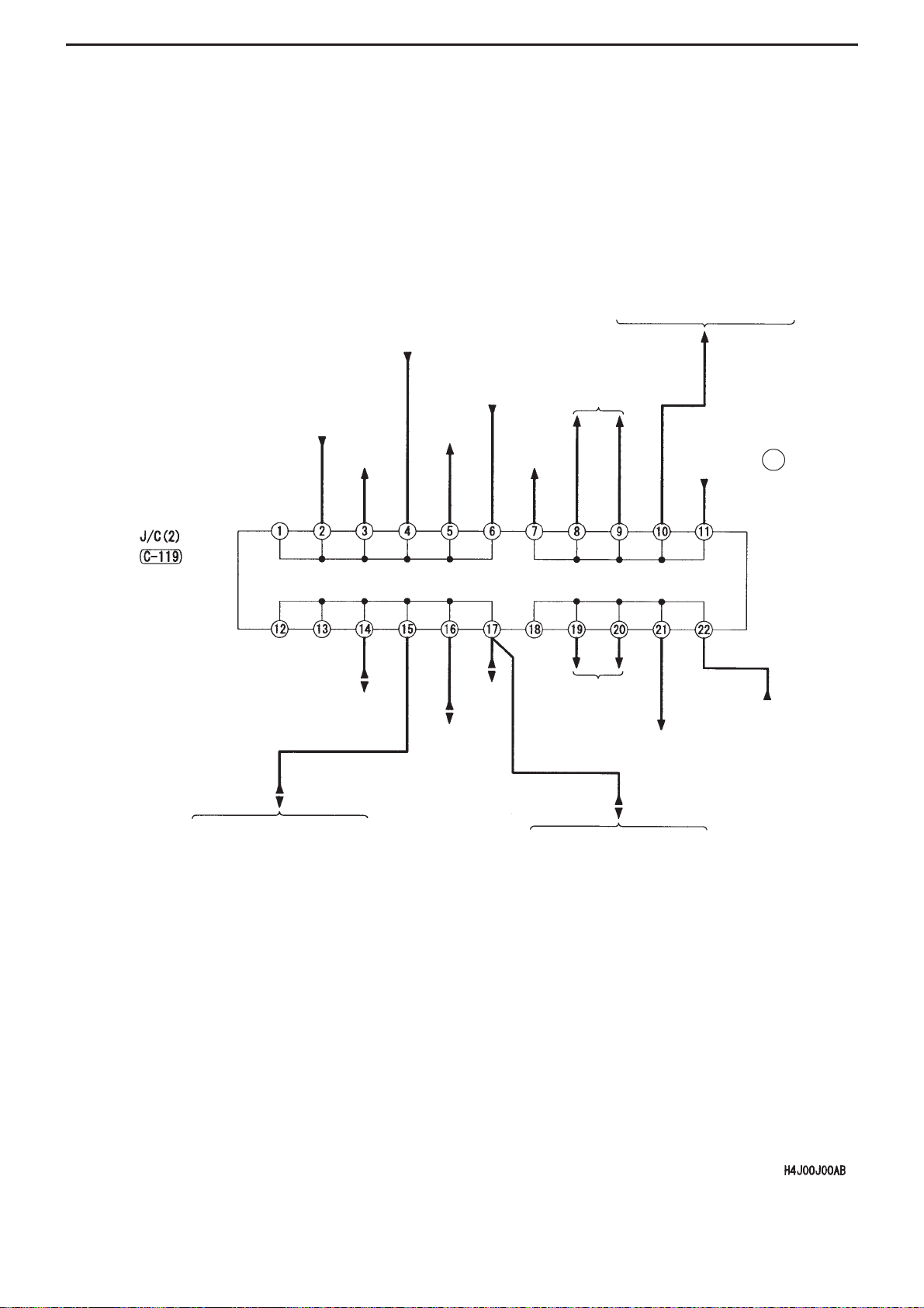
-Safety and
-
(C-119) on line linking ETACS and
diagnosis connector. (No.1 " No.5)
(C-119) on line linking reversing light
and rear combination light (LH).
(No.18 " No.19)
circuit partially changed.
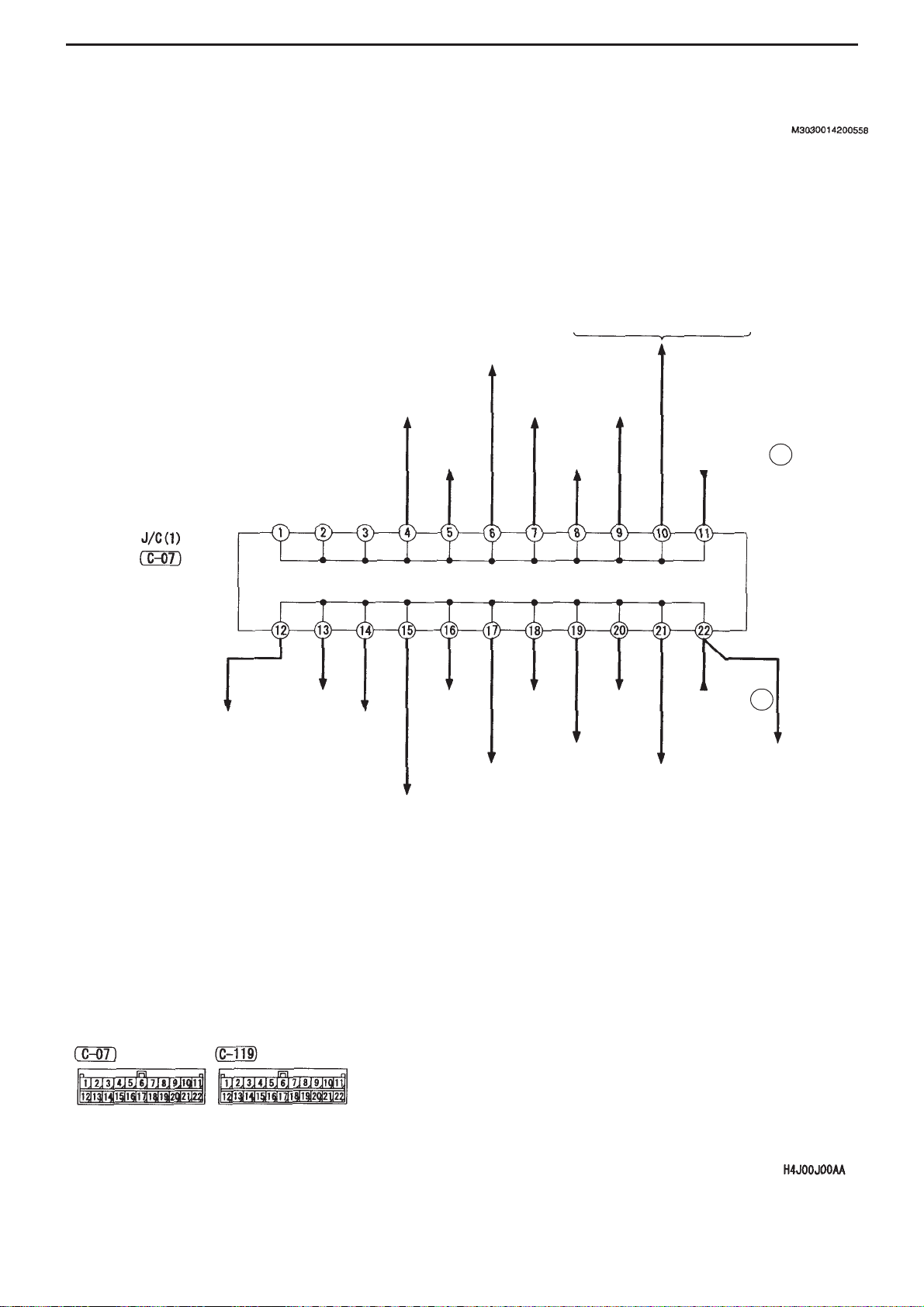
• Change to terminal number in J/C(1)
(C-07) on line inking J/B (general fuse
No.18) and combination meter. (No.4
" No.8)
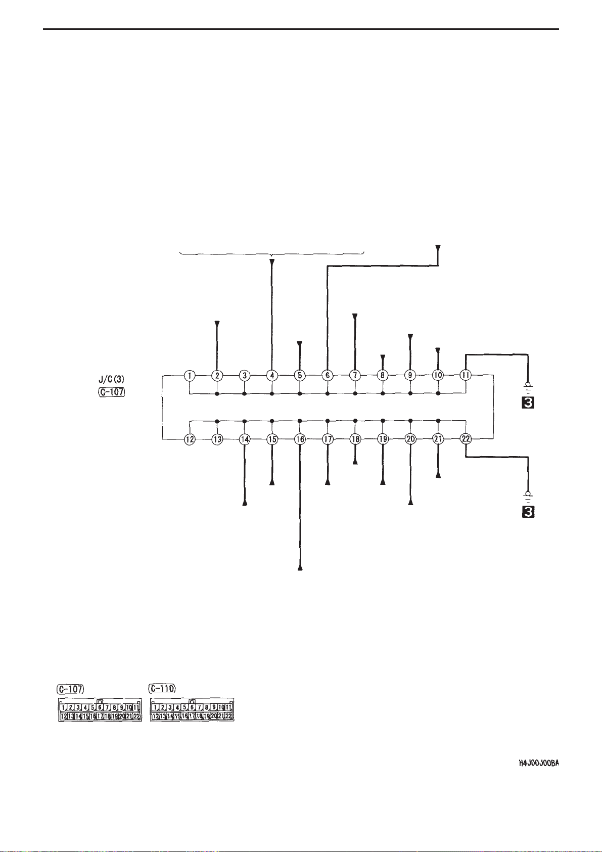
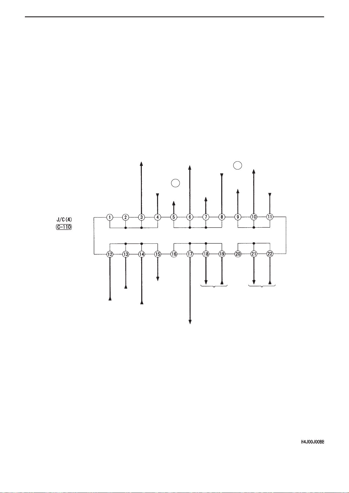
• Change to terminal number in J/C(4)
(C-110) on line linking combination
meter and fuel gauge unit (sub).
(No.20 " No.21)
(C-119) on line linking power window
main switch and diagnosis connector.
(No.12 " No.14)
(C-07) on line linking J/B (general
fuse No. 18) and A/C-ECU. (No.6 "
No.4)
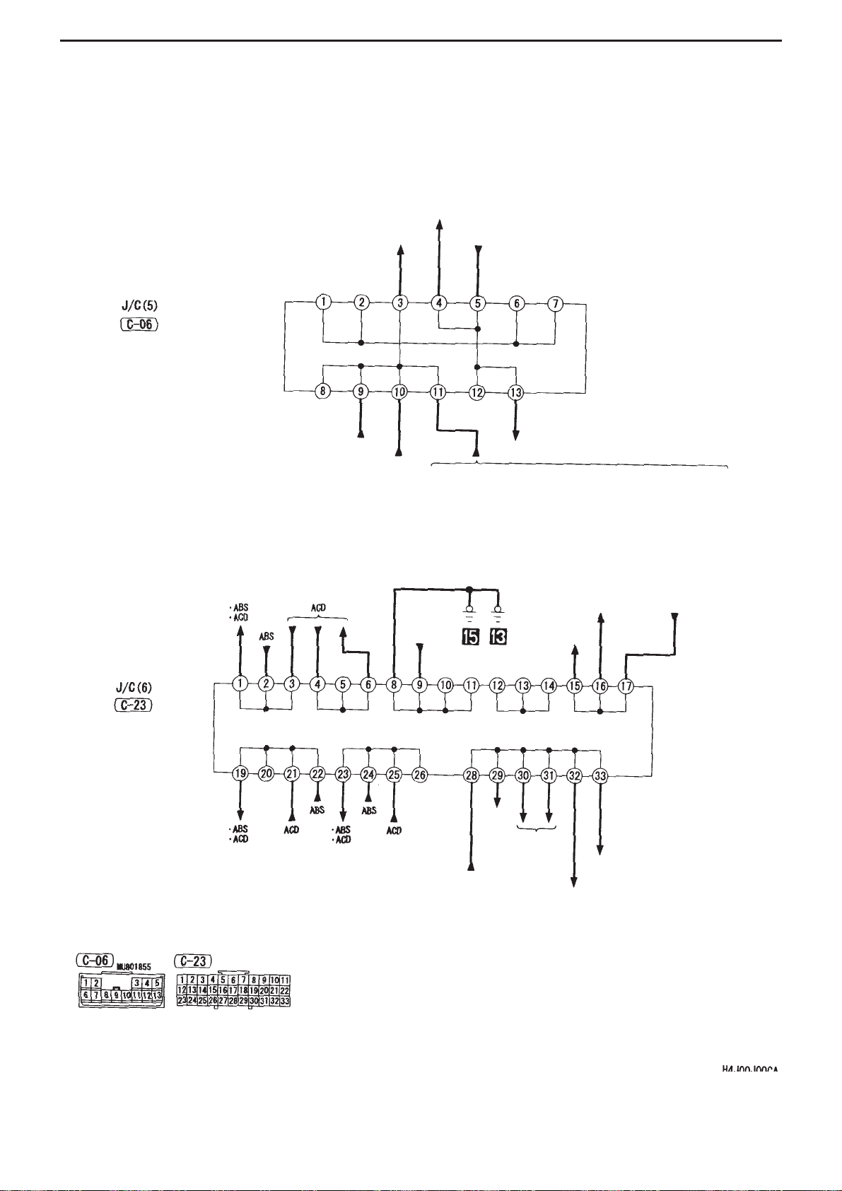
• Change to terminal number in J/C(5)
(C-06) on line linking A/C-ECU and
diagnosis connector. (No.8 " No.9)
conditioning, a new circuit has been
installed.
• Change to terminal number in J/C(2)
(C-119) on line linking ETACS and
diagnosis connector. (No.1 " No.5)
Page 7

GENERAL INFORMATION - DETAILS OF CHANGES
0-4
Main circuit Name of circuit Page Details of change
Accessories
Spare Audio connectors - • Change to terminal number in J/C(1)
(C-07) on line inking J/B (general fuse
No.18) and spare audio connector.
(No.3 " No.7)
Clock - • Change to terminal number in J/C(1)
(C-07) on line inking J/B (general fuse
No.18) and clock. (No.2 " No.6)
Special
Equipment
ABS p.3-32
• Circuit changed due to change in
branching point of connector for
4WD-ECU (C-37) (C-38) (from
instrument panel harness to control
ACD (Vehicles not fitted with
AYC)
p.3-40
harness).
• J/C(6) (C-23) added between ABS-
ECU and 7
connector (C-20) between instrument
panel harness and control harness.
• J/C(6) (C-23) added between ABS-
ECU and 22
connector (C-22) between instrument
panel harness and control harness.
ACD, A YC p.3-48 • Circuit changed due to change in
branching point of connector for
4WD-ECU (C-37) (C-38) (from
instrument panel harness to control
harness).
• Earth No.13 added
• J/C(6) (C-23) added between 4WD-
ECU and 7
connector (C-20) between instrument
panel harness and control harness.
• J/C(6) (C-23) added between 4WD-
ECU and 22
connector (C-22) between instrument
panel harness and control harness.
Intercooler water spray - • Change to terminal number in J/C(1)
(C-07). (No.12 " No.21).
Engine immobiliser system p.3-58 • Partial changes due to removal of
DVD-MMCS.
• Partial changes to circuit, due to
change in installation point of
immobiliser ECU.
Spare general connectors - • Change to terminal numbers in J/C(1)
(C-07) on line linking J/B (general
fuse No.18) / special fuse No.15, and
general spare connectors. (No.7 "
No.5), (No.21 " No.12).
th
terminal of junction
nd
terminal of junction
th
terminal of junction
nd
terminal of junction
Page 8
GENERAL INFORMATION - LIST OF CIRCUIT DIAGRAMS
0-5
List of Circuit Diagrams
M3000006000169
Notes:
1. This list of circuit diagrams indicates whether each circuit has been modified or added.
2. The “●” symbol indicates a circuit that has been modified or added. Diagrams for these circuits are included in
this supplement.
3. The “” symbol indicates a circuit that is unchanged. Details of these circuits can be found in the existing
Electrical Wiring Diagram manual (’03-1 No.1036K77).
4. The “X” symbol indicates a circuit that is unrelated to the vehicle referred to in this manual.
5. The “*1” symbol marks circuits whose names have been changed the previous names.
6. The “*2” symbol marks circuits whose J/C terminal numbers have changed. For more information, please refer
to the “Details of Changes” table above.
Main circuit Name of Circuit Circuit Diagram
J/B J/C Central junction Power supply Start up Ignition Charging Engine control Coolant Lighting
Signalling
Meters
Door opening control
Air conditioning
Headlights (excluding discharge type)
Headlight (discharge type)
Tail lights, side lights, licence plate lights, lighting monitor
warning buzzer
Cabin lights, boot interior light, ignition key cylinder
illumination light, door not closed indicator light *2
Fog lights
Headlight levelling system
Indicator lights, hazard warning lights
Reversing lights *2
Stop lights
Horn
Meters / Gauges *2
Remaining fuel warning light, oil pressure warning light,
brake warning light, seatbelt warning light *2
Electric windows *2
Central door locking (vehicle not fitted with keyless entry)
Central door locking (vehicle fitted with keyless entry)
Heater
Fully automatic air conditioning
Manual air conditioning
!
#
#
#
!
!
!
#
!
!
!
!
!
!
!
!
!
#
!
!
!
!
!
!
!
!
#
Page 9
GENERAL INFORMATION - LIST OF CIRCUIT DIAGRAMS
0-6
Main circuit Name of Circuit Circuit Diagram
Safety / Visibility
Accessories
Special Equipment
Windscreen wipers, washers *2
Rear wiper, washer
Demister (vehicle not fitted with fully automatic A/C)
Demister, door mirror heating elements (vehicle fitted with
fully automatic A/C)
Electric retractable remote control door mirrors *2
Spare Audio connectors *1,2
DVD-MMCS X
Clock *1,2
Cigar lighter, ashtray illumination light
ABS
ACD (vehicle not fitted with AYC)
ACD, A YC
SRS airbags, seatbelt pre-tensioners (vehicle not fitted
with side airbags)
SRS airbags, seatbelt pre-tensioners (vehicle fitted with
side airbags)
Sun roof X
Ignition key reminder buzzer
Intercooler water spray *2
Engine immobiliser system
Security alarm
Spare connectors for fog lights
Spare general connectors *2
!
!
!
!
!
!
!
!
#
#
#
!
!
!
!
#
!
!
!
Page 10

1-1
SECTION 1
WIRING DIAGRAMS
CONTENTS
Engine transmission ..............................1-2 Instrument panel .....................................1-4
Boot interior............................................1-6
Page 11
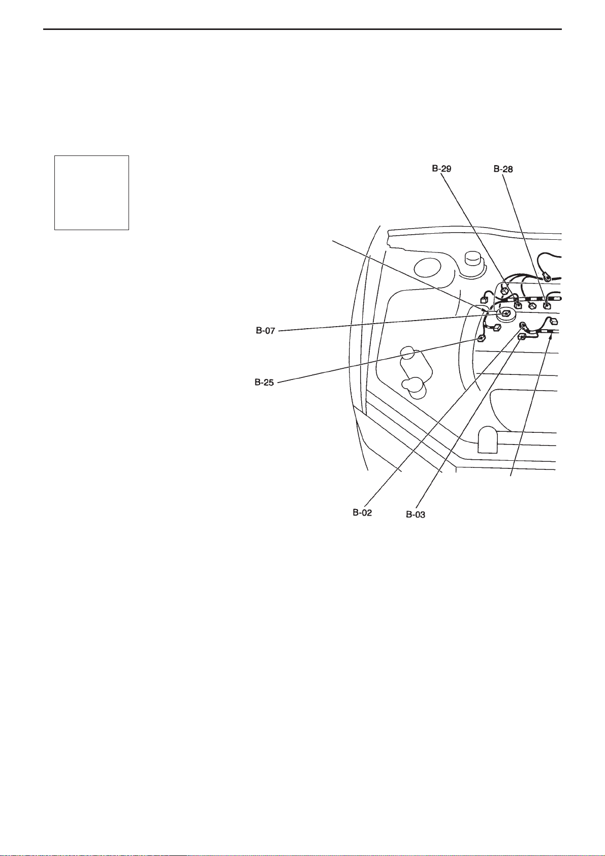
WIRING DIAGRAMS - ENGINE TRANSMISSION
1-2
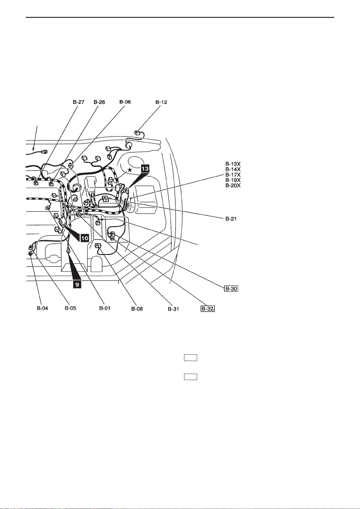
ENGINE TRANSMISSION
M3010000400494
B-01 (1-black) Engine oil pressure switch
B-02 (1) Alternator
B-03 (4-grey) Alternator
B-04 (1) Starter
B-05 (1-black) Starter
B-06 (4-black) Throttle position sensor
B-07 (2-black) Purge control solenoid valve
B-08 (7-black) Airflow sensor
B-12 (5-grey) Windscreen wiper motor
B-13X (1) Engine speed detection connector
B-14X (5) Starter relay
B-17X (4) Ignition coil relay
Connector
symbol -
B
-01
∫
-32
AC311230AB
Control harness
Battery harness
Page 12
WIRING DIAGRAMS - ENGINE TRANSMISSION
1-3
B-19X (4) Engine control relay
B-20X (4) A/C compressor relay
B-21 (10-black) Junction between control harness and
battery harness
B-25 (4-black) O
2
sensor
B-26 (2-black) Indicator 4
B-27 (2-black) Indicator 3
B-28 (2-black) Indicator 2
B-29 (2-black) Indicator 1
(2-grey) Wastegate solenoid valve 1
B-31 (6-black) Junction between control harness and
transmission harness
(2-grey) Wastegate solenoid valve 2
Note : Boxed connector numbers indicate
connectors with changed names, or new,
additional connectors.
B-32
B-32
Earth cable
Transmission harness
AC311231AB
Page 13
WIRING DIAGRAMS - INSTRUMENT PANEL
1-4
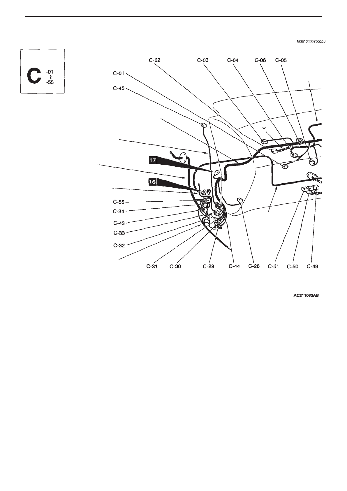
INSTRUMENT PANEL
C-01 (4) Register (vehicle not fitted with full auto
A/C)
C-02 (2-red) Front pass. seat airbag module (squib)
C-03 (7) Internal / external air changeover damper
motor
C-04 (7) Junction between instrument panel
harness and A/C harness (vehicle not
fitted with full auto A/C)
(13) Junction between instrument panel
harness and A/C harness (vehicle fitted
with full auto A/C)
C-05 (2) Air thermo sensor (vehicle fitted with full
auto A/C)
C-06 (13) J/C (5)
C-07 (22-grey) J/C (1)
C-08 (6) Air mix door motor and potentiometer
(vehicle with full auto A/C)
C-09 (2) Heater water temperature sensor (vehicle
with full auto A/C)
C-10 (5) Blower outlet changeover damper motor
& potentiometer (vehicle with full auto
A/C)
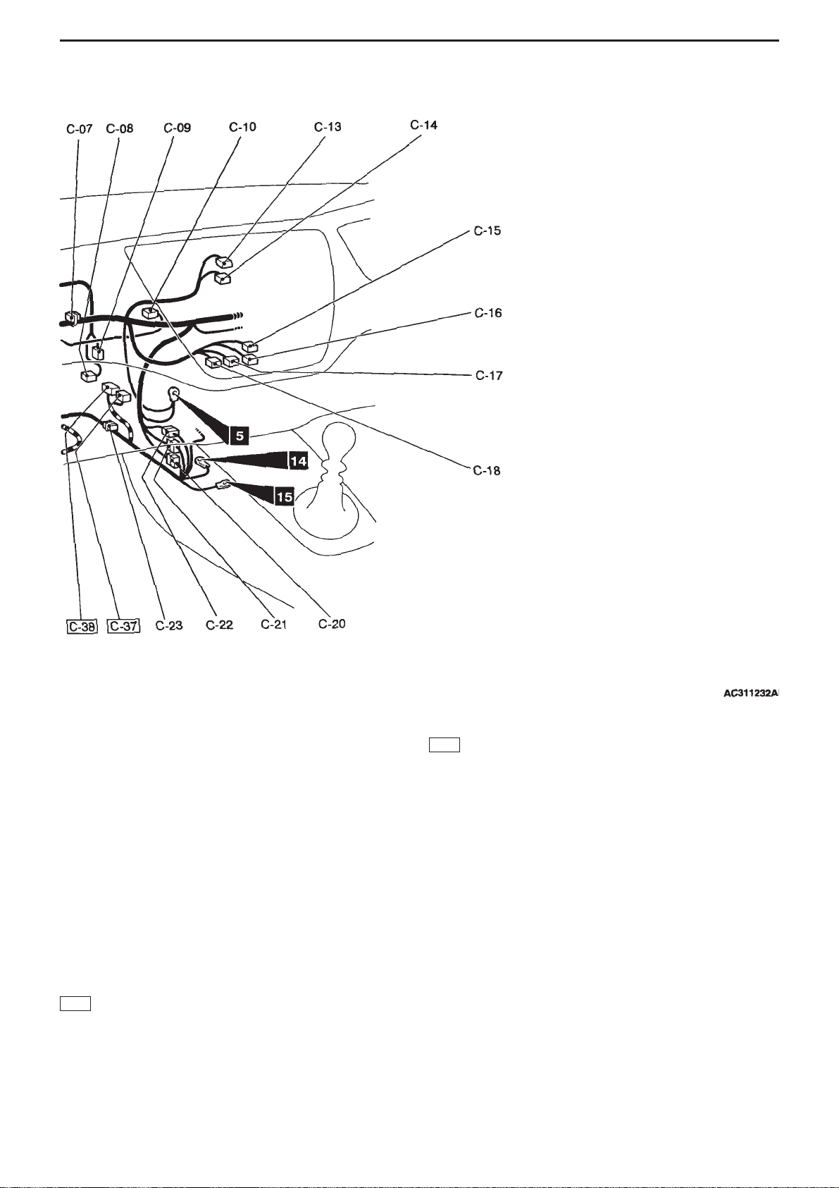
C-13 (4) Clock
C-14 (4) Hazard switch
C-15 (6) Blower switch
(vehicle not fitted with full auto A/C)
C-16 (12-black) Heater control unit
(vehicle with heater) or A/C-ECU
(vehicle with manual A/C)
C-17 (20-black) A/C-ECU (vehicle with full auto A/C)
C-18 (16-black) A/C-ECU (vehicle with full auto A/C)
C-20 (22-blue) Junction between instrument panel
harness and control harness
C-21 (10-grey) Junction between instrument panel
harness and control harness
C-22 (25) Junction between instrument panel
harness and control harness
Connector
symbol
Front passenger’s side
Instrument panel harness
Tweeter sub-harness
Front
harness (LH)
Front door
harness (LH)
Floor
harness (LH)
A/C harness
Control
harness
Page 14
WIRING DIAGRAMS - INSTRUMENT PANEL
1-5
C-23 (33) J/C (6)
C-28 (2) Blower motor
(Vehicle not fitted with full auto A/C)
(6) Blower pulse controller
(Vehicle fitted with full auto A/C)
C-29 (13) Junction between instrument panel
harness & floor harness (LH)
C-30 (11-grey*) Junction between instrument panel
harness & floor harness (LH)
C-31 (25) Junction between instrument panel
harness & front harness (LH)
C-32 (3) Junction between instrument panel
harness & front harness (LH)
C-33 (16) Junction between instrument panel
harness & front door harness (LH)
C-34 (16) Junction between control harness & front
harness (LH)
(22) 4WD-ECU
(26) 4WD-ECU
C-43 (1-grey) Junction between control harness and
floor harness (LH)
C-44 (2) Junction between instrument panel
harness and tweeter sub-harness
C-45 (2) Tweeter (LH)
C-49 (35-grey) Engine ECU
C-50 (28-grey) Engine ECU
C-51 (30-grey) Engine ECU
C-55 (2) Spare connector
Note :
• Aconnector colour marked * indicates the male connector.
The female connector is black.
• Boxed connector numbers indicate connectors in harness
routes that have been changed.
C-38
C-37
Page 15
WIRING DIAGRAMS - BOOT INTERIOR
1-6
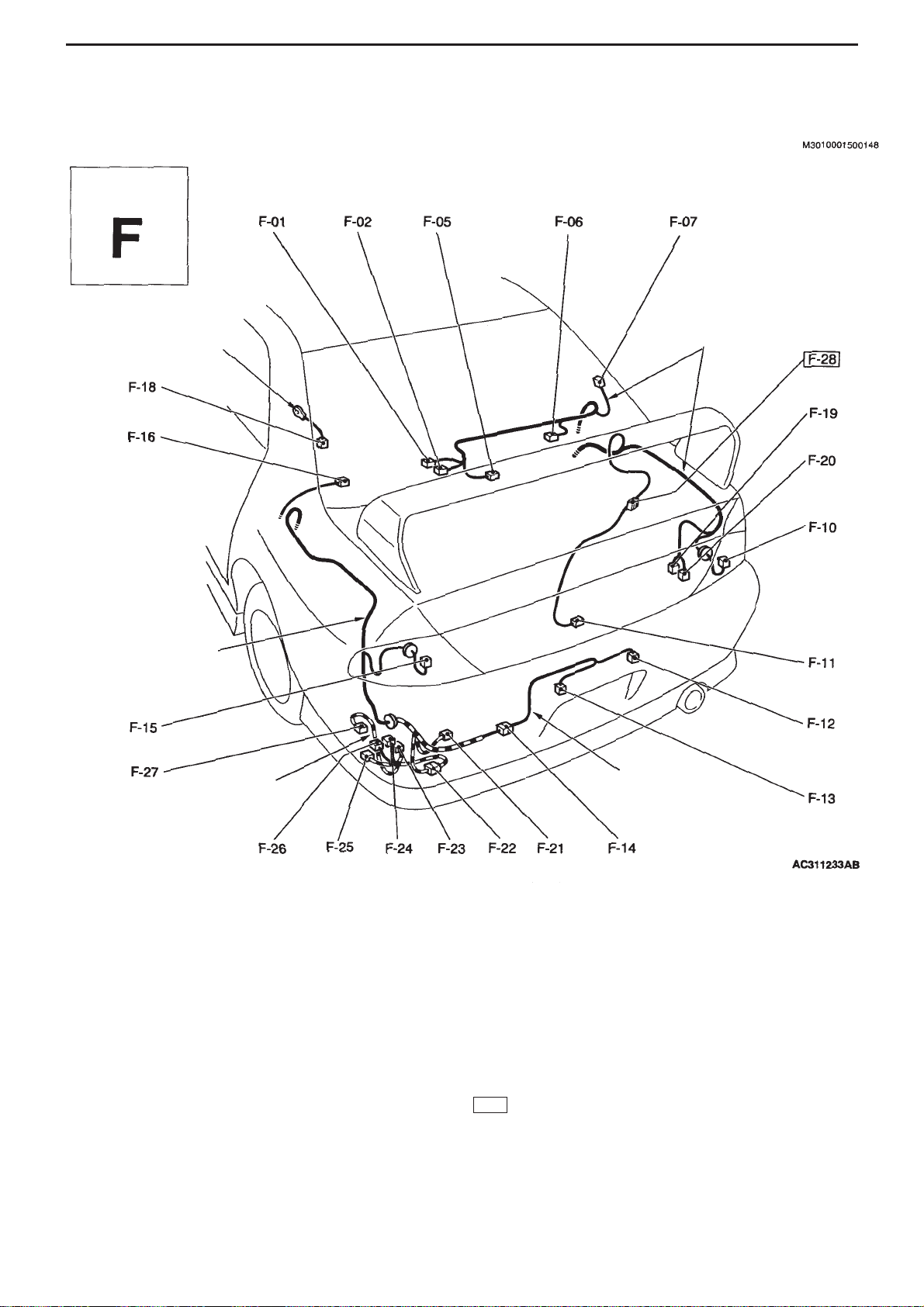
BOOT INTERIOR
F-01 (2) Boot interior light
F-02 (2-grey) High-mount stop light
F-05 (4) Rear wiper motor
F-06 (2) Rear speaker (RH)
F-07 (1) Demister (+)
F-10 (6-black) Rear combination light (RH)
F-11 (1) Book interior light switch
F-12 (2-grey) Licence plate light (RH)
F-13 (2-grey) Licence plate light (LH)
F-14 (2-grey) Junction between floor harness (LH) &
bumper harness
F-15 (6-black) Rear combination light (LH)
F-16 (2) Rear speaker (LH)
F-18 (1-black) Demister (-)
F-19 (2) Windscreen washer motor
F-20 (2-green) Rear washer motor
F-21 (2-black) Electrical pump
F-22 (8-grey) Junction between floor harness (LH) and
4WD harness (vehicle with AYC)
F-23 (2-black) Directional valve (left) (vehicle with AYC)
F-24 (2-black) Directional valve (right) (vehicle with AYC)
F-25 (3-black) Proportional valve (for ACD)
F-26 (3-black) Proportional valve (for AYC) (vehicle with
AYC)
F-27 (3-black) Pressure sensor
(2) Spare connector
• Boxed connector numbers indicate newly added connectors.
F-28
Demister earth
Floor
harness (LH)
4WD
harness
Bumper
harness
Floor harness
(RH)
Connector
symbol
Page 16

2-1
SECTION 2
COMPONENT INSTALLATION
POSITIONS
CONTENTS
ECU ..........................................................2-2 Solenoid Valves ......................................2-2
Page 17
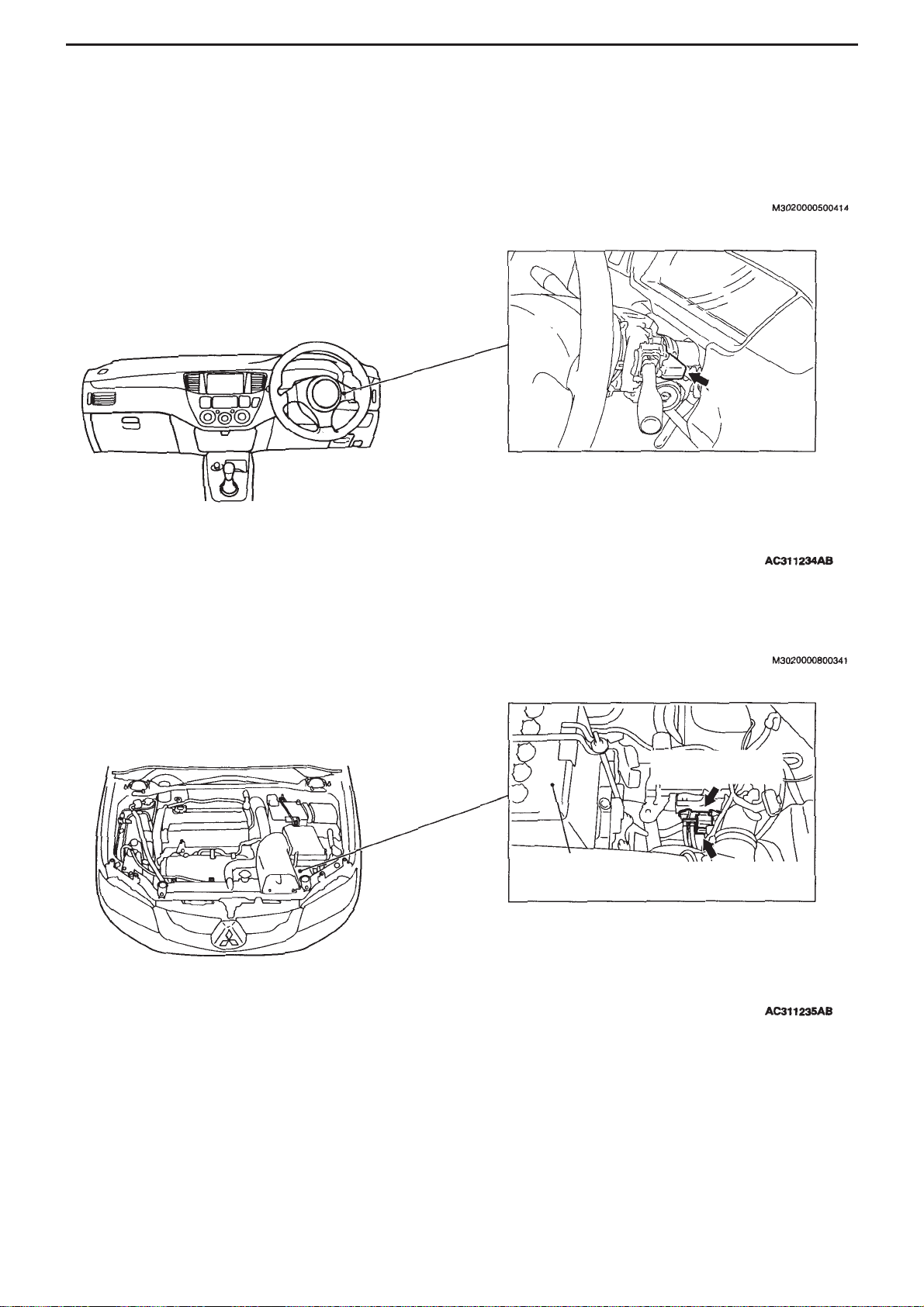
COMPONENT INSTALLATION POSITIONS - ECU
2-2
ECU
Immobiliser
ECU
Wastegate solenoid
valve 1
Battery
Wastegate solenoid valve 2
Page 18

3-1
SECTION 3
CIRCUIT DIAGRAMS
CONTENTS
J/C ............................................................3-2
Central Junction .....................................3-8
Power Supply........................................3-10
Engine Control......................................3-16
Signalling
Stop lights........................................................3-24
Air Conditioning
Manual A/C ......................................................3-26
Special Equipment
ABS..................................................................3-32
ACD (vehicle without AYC)..............................3-40
ACD, A YC........................................................3-48
Engine immobiliser system..............................3-58
Page 19
COMPONENT INSTALLATION POSITIONS - J/C
3-2
J/C
Note :
In an actual vehicle, any of the terminals connected in the J/C
may be used. Therefore, the terminal numbers given in the
circuit diagrams may not coincide with the terminal arrangement
in the actual vehicle.
• Windscreen wiper
& washer
• Indicator lights,
hazard warning
lights
• Tail lights, side
lights, licence
plate lights,
lightning monitor
warning buzzer
• Fog lights
• Headlights
• Headlight levelling
system
• Rear wiper /
washer
Full auto
A/C
General
spare
connector
Clock
Spare audio
connector
• Warning
lights
• Meter
gauge
• ACD
• Engine
control
J/B
General fuse
(
)
18
General
spare
connector
Fog light
Spare audio
connector
• Demister (Vehicle
w/out full auto A/C)
• Demister, door
mirror heating
element (vehicle
with full auto A/C)
• Heater
• Full auto A/C
• Manual A/C
Cigar lighter
Ashtray
illumination
light
Clock
ACD
Headlight
levelling
system
Indicator light
Hazard
warning lights
Intercooler
water spray
General fuse
15
• Meter gauge
• Tail lights, side
lights, licence
plate lights,
lighting monitor
warning buzzer
Page 20
COMPONENT INSTALLATION POSITIONS - J/C
3-3
•Windscreen wiper
& washer
•Indicator lights,
hazard warning
lights
•Tail lights, side
lights, licence
plate lights,
lighting monitor
warning buzzer
•Fog lights
•Full auto A/C
• Headlights
• Headlight levelling
system
•Manual A/C
• Cooling
•Windscreen wiper
& washer
•Electric retractable
remote control
door mirror
• Cabin lights, boot
interior light,
ignition key
cylinder
illumination light,
door not properly
closed indictor light
• Heater
• Full auto A/C
•Manual A/C
•ABS
• ACD
Meter
gauge
Diagnosis
meter
Vehicle
speed
sensor
General
spare
connector
Power
window
•Windscreen
wiper
& washer
•Indicator lights,
hazard warning
lights
•Tail lights, side
lights, licence
plate lights,
lighting monitor
warning buzzer
•Fog lights
• Headlights
•Ignition key
reminder buzzer
•Windscreen wiper
& washer
•Indicator lights,
hazard warning
lights
•Tail lights, side
lights, licence
plate lights,
lighting monitor
warning buzzer
•Electric windows
• Fog lights
• Headlights
•Rear wiper /
washer
•Windscreen
wiper &
washer
•Indicator
lights, hazard
warning lights
•Tail lights, side
lights, licence
plate lights,
lighting
monitor
warning
buzzer
• Fog lights
• Headlights
•Rear wiper /
washer
• Reversing light
•Rear wiper /
washer
Rear wiper /
washer
Reversing
light
Diagnosis
connector
J/B
General fuse
(
)
5
Page 21
CIRCUIT DIAGRAMS - J/C
3-4
J/C (cont’d)
•Ignition key
reminder buzzer
•Windscreen wiper
& washer
•Security alarm
• Central door
locking
•Indicator lights,
hazard warning
lights
•Tail lights, side
lights, licence
plate lights,
lighting monitor
warning buzzer
•Electric
retractable
remote control
door mirror
•Electric windows
• Heater
•Fog lights
• Full auto A/C
• Headlights
•Manual A/C
•Rear wiper /
washer
• Cabin lights, boot
interior light,
ignition key
cylinder
illumination light,
door not properly
closed indictor
light
• Ignition key reminder
buzzer
• Intercooler water
spray
• Security alarm
• Central door locking
(vehicle with keyless
entry)
• Cabin lights, boot
interior light, ignition
key cylinder
illumination light,
door not properly
closed indictor light
Fog lights
• Clock
•Indicator
lights,
hazard
warning
lights
•ABS
• ACD
Headlight
levelling
system
Electric
retractable
remote
control door
mirror
•Warning lights
•Starter
Headlight
levelling
system
Fog lights
Cigar lighter
Ashtray illumination light
• Demister
(vehicle
w/out full
auto A/C)
• Demister,
door
mirror
heating
element
(vehicle
with full
auto A/C)
•Heater
• Full auto
A/C
•Manual
A/C
ACD
Intercooler
water spray
Indicator
lights,
hazard
warning
lights
Meter gauge
Page 22
CIRCUIT DIAGRAMS - J/C
3-5
Electric retractable
remote control door
mirrors
J/B
General
fuse
(
)
11
J/B
General
fuse
(
)
13
General spare
connector
Spare
audio
connector
Clock
• Fog lights
• Spare
connector
for fog lights
Fog
lights
•Fog lights
• Spare
connector
for fog lights
SRS airbags,
seatbelt pre-
tensioners
• ABS
• ACD
Engine
immobiliser
system
Engine
control
Diagnosis
connector
Cabin lights,
boot interior
light, ignition
key cylinder
illumination
light, door not
properly closed
indicator light
• Central door
locking
(vehicle with
keyless entry)
• Cabin lights,
boot interior
light, ignition
key cylinder
illumination
light, door not
properly
closed
indicator light
•Warning lights
• Meter gauge
Page 23
CIRCUIT DIAGRAMS - J/C
3-6
J/C (cont’d)
Diagnosis
connector
Security
alarm
•Security alarm
•Horn
Full auto A/C
• ABS
• ACD
Horn
• Ignition key
reminder
buzzer
•Windscreen
wiper &
washer
• Security alarm
• Central door
locking
•Turn signal
lights, hazard
warning lights
•Tail lights,
position lights,
licence plate
lights, lighting
monitor
warning
buzzer
•Electric
stowable
remote control
door mirrors
• Power
windows
• Fog lamps
• Headlights
• Rear wiper /
washer
• Cabin lights,
boot interior
light, ignition
key cylinder
illumination
light, door not
properly
closed
indicator light
Engine
control
• Engine
control
• Ignition
Meter gauge
• Engine control
• Meter gauge
• Ignition
• Engine immobiliser
system
• Engine control
• Full auto A/C
• Cooling
Engine
control
• Engine
immobiliser
system
• Engine
control
• Full auto A/C
• Cooling
Engine
immobiliser
system
Page 24

CIRCUIT DIAGRAMS
3-7
(Notes)
Page 25

CIRCUIT DIAGRAMS - CENTRAL JUNCTION
3-8
Central Junction
M3030000300552
Fusible link (Relay box inside engine space)
No. Circuit Type Housing colour Rated current (A)
2 Full auto air conditioning;
manual air conditioning;
cooling
Connector type Red 50
Forward
direction of
vehicle
Page 26

CIRCUIT DIAGRAMS - CENTRAL JUNCTION
3-9
Fusible link (Relay box inside engine space)
Power supply circuit Fuse No. Rated
current (A)IDcolour
Applied loads
Battery / Alternator (fusible
link No. 6)
3 20 Yellow O2sensor, secondary are
control solenoid valve, idle
speed control servo, ignition
coil 1, ignition coil 2, waste
gate solenoid valve 1, waste
gate solenoid valve 2, air
flow sensor, engine ECU,
engine control relay, cam
position sensor, crank angle
sensor, purge control
solenoid valve, fuel pressure
solenoid valve, radiator fan
control relay, register (for
injector)
10 20 Yellow Fuel pump relay 3, fuel pump
register, fuel pump & fuel
gauge unit (main)
Forward
direction of
vehicle
Page 27

CIRCUIT DIAGRAMS - POWER SUPPLY
3-10
Power Supply
Battery
Fusible link
Special fuse
Starter
Charging
• Full auto A/C
•Manual A/C
• Cooling
• Full auto A/C
• Manual A/C
• Cooling
Engine
control
•Security alarm
• Central door
locking
(vehicles with
keyless entry)
•Turn signal
lights, hazard
warning lights
Charging
• Full auto
A/C
•Manual
A/C
• Cooling
• ABS
• ACD
•Stop
lights
• Heater
• Full auto
A/C
•Manual
A/C
Page 28

CIRCUIT DIAGRAMS - POWER SUPPLY
3-11
Note:
*1 : except discharge headlights
*2 : discharge headlights
Headlight
relay: LO
Headlight
relay : HI
Tail light
relay
Front ECU
• Engine
immobiliser
system
• Engine
control
• Ignition
• Security
alarm
• Horn
• Fog lamps
• Spare
connectors for
fog lamps
Headlights Headlights
Headlights
Headlights
Headlight levelling system
Tail lights, position
lights, licence
plate lights,
lighting monitoring
warning buzzer
• ACD
•Intercooler water spray
• Spare audio connector
• Clock
•Cigar lighter, ashtray
illumination light
• Meter gauge
•Turn signal lights,
hazard warning lights
•Tail lights, position
lights, licence plate
lights, lighting monitor
warning buzzer
•Demister (vehicle w/out
full auto A/C)
• Demister, door mirror
heating elements,
(vehicle with full auto
A/C)
• General spare
connector
• Heater
• Fog lamps
• Full auto A/C
• Headlight levelling
system
Page 29

CIRCUIT DIAGRAMS - POWER SUPPLY
3-12
Power supply (cont’d)
Fusible link
4
Ignition
switch
Special
fuse
Intercooler
water spray
• Engine control
•Starter
• ABS
• ACD
• SRS airbags, seat
pre-tensioners
• Ignition key reminder
buzzer
• Intercooler water
spray
•Windscreen wiper /
washer
•Warning lights
• Engine control
• Meter gauge
• Charging
•Security alarm
• Central door locking
•Turn signal lights,
hazard warning lights
•Tail lights, position
lights, licence plate
lights, lighting monitor
warning buzzer
•Electric stowable
remote control door
mirrors
• Power windows
• General spare
connectors
• Fog lamps
• Headlights
•Rear wiper / washer
• Cabin lights, boot
interior light, ignition
key cylinder
illumination light, door
not properly closed
indicator lamp
• SRS airbags, seatbelt
pre-tensioners
•Reversing lights
• Rear wiper / washer
Engine control
Ignition
Page 30

CIRCUIT DIAGRAMS - POWER SUPPLY
3-13
•ABS
• ACD
• Intercooler water spray
•Windscreen wiper /
washer
•Turn signal lights,
hazard warning lights
•Tail lights, position
lights, licence plate
lights, lighting monitor
warning buzzer
•Heater
• Fog lamps
• Full auto A/C
• Headlights
• Headlight levelling
system
•Manual A/C
• Cooling
• ABS
• ACD
Windscreen
wiper / washer
Cigar lighter,
ashtray
illumination lamp
Electric
stowable
remote
control door
mirrors
• Spare audio
connector
• Clock
• General spare
connector
•Cabin lights,
boot interior
light, ignition
key cylinder
illumination
light, door not
properly closed
indicator lamp
• Rear wiper/
washer
•Cabin lights,
boot interior
light, ignition
key cylinder
illumination
light, door
not properly
closed
indicator
lamp
Page 31

CIRCUIT DIAGRAMS - POWER SUPPLY
3-14
Power Supply (cont’d)
Fusible
link
1
Fusible
link
5
• ABS
• ACD
• SRS airbags, seat pretensioners
• Ignition key reminder
buzzer
•Windscreen wiper /
washer
• Engine immobiliser
system
• Engine control
•Security alarm
• Central door locking
•Turn signal lights,
hazard warning lights
•Tail lights, position
lights, licence plate
lights, lighting monitor
warning buzzer
•Electric stowable remote
control door mirrors
• Power windows
• Fog lamps
• Full auto A/C
• Headlights
• Rear wiper / washer
•Cabin lights, boot interior
light, ignition key cylinder
illumination light, door
not properly closed
indicator lamp
• ACD
• Ignition key reminder
buzzer
•Windscreen wiper /
washer
•Warning lights
• Engine control
• Spare audio connector
• Clock
• Meter gauge
•Security alarm
• Central door locking
•Turn signal lights,
hazard warning lights
•Tail lights, position lights,
licence plate lights,
lighting monitor warning
buzzer
•Electric stowable remote
control door mirrors
• Power windows
•General spare connector
• Fog lamps
•Full auto A/C
• Headlights
• Headlight levelling
system
• Rear wiper / washer
• Cabin lights, boot
interior light, ignition key
cylinder illumination
light, door not properly
closed indicator lamp
•Heater
•Full auto
A/C
•Manual A/C
Power
windows
J/B
General fuse
(
)
5
Demister relay
Demister, door mirror
thermal element (vehicle
with full auto A/C)
•Demister (vehicle
w/out full auto A/C)
• Demister, door mirror
thermal element
(vehicle with full auto
A/C)
•Demister (vehicle
w/out full auto
A/C)
• Demister, door
mirror thermal
element (vehicle
with full auto
A/C)
Page 32

CIRCUIT DIAGRAMS - POWER SUPPLY
3-15
(Notes)
Page 33

CIRCUIT DIAGRAMS - ENGINE CONTROL
3-16
ENGINE CONTROL
M3030000801516
Battery
Special fuse
Engine
control
relay
Engine
ECU
Page 34

CIRCUIT DIAGRAMS - ENGINE CONTROL
3-17
Ignition switch
Fuel
pump
relay
Fuel
pump
relay
Combination
meter
•Windscreen
washer/wiper
•Turn signal lights /
hazard warning
lights
•Tail lights, position
lights, licence
plate lights,
lighting monitor
warning buzzer
• Fog lights
• Headlights
• Rear
washer/wiper
Page 35

CIRCUIT DIAGRAMS - ENGINE CONTROL
3-18
Engine Control (cont’d.)
Engine control relay
Air
processor
Engine
ECU
Throttle position
sensor
Water temperature
sensor
Atmospheric
pressure sensor
Intake air
temperature
sensor
Cam shaft
position sensor
Page 36

CIRCUIT DIAGRAMS - ENGINE CONTROL
3-19
Engine control relay
J/C (6)
(Engine control relay)
Crank angle
sensor
Register (for
indictor)
Indicator
Indicator
Indicator
Indicator
Engine
control relay
Knock
sensor
O2sensor
Page 37

CIRCUIT DIAGRAMS - ENGINE CONTROL
3-20
Engine Control (cont’d.)
Ignition
switch (ST)
Engine control relay
Starter
relay
Idle speed
control
servo
Fuel
pressure
solenoid
valve
Waste
gate
solenoid
valve
Engine ECU
Engine speed
detection
connector
Power steering fluid
pressure switch
Page 38

CIRCUIT DIAGRAMS - ENGINE CONTROL
3-21
Engine control relay
Waste gate
solenoid
valve 2
Purge control
solenoid
valve
Secondary
air control
solenoid
valve
Intercooler water spray
• Full auto A/C
•Manual A/C
• Cooler
• Heater
• Full auto A/C
• Manual A/C
Page 39

CIRCUIT DIAGRAMS - ENGINE CONTROL
3-22
Engine Control (cont’d.)
J/B
Common
fuse
(
)
2
Fusible link
1
Engine ECU
Vehicle
speed
sensor
Engine
immobilizer
system
Diagnostics
connector
Diagnostics
connector
Front view
Front view
Page 40

CIRCUIT DIAGRAMS - ENGINE CONTROL
3-23
Remarks
* :
•Windscreen washer / wiper
• Meter gauges
•Electric retractable door mirrors
•Generic spare connectors
• Cabin lights, boot interior light,
ignition key cylinder
illumination light, door not
properly closed reminder light
J/B
(Fuel pump relay 2)
Fuel pump
relay 3
Fuel
pump
register
Fuel pump
& fuel gauge
unit (main)
Back-up
power supply
Engine ECU
Page 41

CIRCUIT DIAGRAMS - SIGNALLING
3-24
Signalling
Stop lights
Battery
General
fuse
Stop light
switch
Rear
combination
light (stop : LH)
Rear
combination
light (stop : RH)
High-mount
stop light
Spare
connector
Page 42

CIRCUIT DIAGRAMS
3-25
(Notes)
Page 43

CIRCUIT DIAGRAMS - AIR CONDITIONING
3-26
Air Conditioning
Manual Air Conditioning
Fusible
link
1
Ignition
switch (IG2)
Blower
relay
Blower
switch
Register
Blower
motor
Intercooler
water spray
Page 44

CIRCUIT DIAGRAMS - AIR CONDITIONING
3-27
J/B
(general fuse)
5
J/B (general
fuse)
5
Front ECU
(tail light relay)
Register
Air thermo sensor
Internal / external
changeover
damper motor
Special fuse
Tail lights, side lights,
licence plate lights,
lighting monitor
warning buzzer
• Meter gauge
•Tail lights, side
lights, licence plate
lights, lighting
monitor warning
buzzer
A/C switch, internal/external changeover damper motor, ILL
Demister
Page 45

CIRCUIT DIAGRAMS - AIR CONDITIONING
3-28
Manual Air Conditioning (cont’d)
Fusible link
2
Engine control relay
Radiator fan
control relay
Radiator fan controller
Input signal
processor
Temperature
detection
Drive circuit
Current
detection
Equalizing
circuit
Field effect
transistor circuit
Radiator fan
motor
Page 46

CIRCUIT DIAGRAMS - AIR CONDITIONING
3-29
General
fuse
Condenser
fan relay
(HI)
Condenser
fan motor
Battery
J/C (2)
(General fuse)
5
Engine ECU
•Windscreen wiper /
washer
•Indicator lights,
hazard warning lights
•Tail lights, side
lights, licence plate
lights, lighting
monitor warning
buzzer
• Fog lights
• Headlights
• Headlight levelling
system
Page 47

CIRCUIT DIAGRAMS - AIR CONDITIONING
3-30
Manual Air Conditioning (cont’d)
Battery
J/C(2)
(General fuse)
5
Radiator fan
controller
A/C
compressor
relay
General fuse
A/C
compressor
Cooling
temperature
switch
Magnetic
switch
Dual
pressure
switch
Low pressure side
ONOFF
: 196kPa
OFFON
: 221kPa
High pressure side
ONOFF
: 3138kPa
OFFON
: 2550kPa
Engine ECU
Page 48

CIRCUIT DIAGRAMS
3-31
(Notes)
Page 49

CIRCUIT DIAGRAMS - SPECIAL EQUIPMENT
3-32
Special Equipment
ABS
Fusible link
3
Ignition switch
(IG2)
Ignition switch
(IG1)
Battery
General
fuse
Combination
meter
Stop light switch
Stop lights
Solenoid valve
power supply
Motor power
supply
Power
supply
Page 50

CIRCUIT DIAGRAMS - SPECIAL EQUIPMENT
3-33
Note:
* :
•Windscreen wiper / washer
• Engine control
• Meter gauge
• Indicator lights, hazard warning
lights
•Tail lights, side lights, licence
plate lights, lighting monitor
warning buzzer
•Electric retractable remote
control door mirror
•General spare connector
•Fog lights
• Headlights
• Rear wiper / washer
• Cabin lights, boot interior light,
ignition key cylinder illumination
light, door not properly closed
indicator light
Motor power
supply
Motor
Hydraulic unit
Solenoid valve
Page 51

CIRCUIT DIAGRAMS - SPECIAL EQUIPMENT
3-34
ABS (cont’d)
Ignition switch (IG2)
Front / rear
G sensor
Lateral G
sensor
Page 52

CIRCUIT DIAGRAMS - SPECIAL EQUIPMENT
3-35
Brake
warning
light
Parking brake
switch
Page 53

CIRCUIT DIAGRAMS - SPECIAL EQUIPMENT
3-36
ABS (cont’d)
Ignition switch (IG2)
• Intercooler
water spray
•Heater
• Full auto A/C
• Manual A/C
Steering sensor
Page 54

CIRCUIT DIAGRAMS - SPECIAL EQUIPMENT
3-37
Front : LH
Front : RH
Rear : LH
Rear : RH
ABS sensors
Page 55

CIRCUIT DIAGRAMS - SPECIAL EQUIPMENT
3-38
ABS (cont’d)
Fusible link
1
Diagnosis
connector
Front view
Page 56

CIRCUIT DIAGRAMS
3-39
(Notes)
Page 57

CIRCUIT DIAGRAMS - SPECIAL EQUIPMENT
3-40
ACD (Vehicle not fitted with AYC)
Fusible link
1
Ignition switch
(IG2)
Battery
General fuse
Stop light
switch
Stop light
Back-up
power supply
Engine
control
Power
supply
Page 58

CIRCUIT DIAGRAMS - SPECIAL EQUIPMENT
3-41
Ignition switch (IG2)
Front / Rear
G sensor
Lateral G
sensor
Brake warning
light
Parking brake
switch
Page 59

CIRCUIT DIAGRAMS - SPECIAL EQUIPMENT
3-42
ACD (Vehicle not fitted with AYC) (cont’d)
Front ECU
(tail light relay)
Special
fuse
Tail lights, side
lights, licence
plate lights,
lighting monitoring
warning buzzer
• Meter gauges
•Tail lights, side
lights, licence plate
lights, lighting
monitoring warning
buzzer
ACD
mode
switch
Ignition switch
(IG1)
•Windscreen wiper /
washer
• Engine control
• Meter gauge
•Indicator light, hazard
lights
•Tail lights, side lights,
licence plate lights,
lighting monitoring
warning buzzer
•Electric retractable
remote control door
mirrors
•General spare
connectors
• Fog lights
• Headlights
• Rear wiper / washer
• Cabin lights, boot
interior light, ignition
key cylinder illumination
light, door not properly
closed indicator light
Combination
meter
Page 60

CIRCUIT DIAGRAMS - SPECIAL EQUIPMENT
3-43
Engine ECU
Throttle position
sensor
Page 61

CIRCUIT DIAGRAMS - SPECIAL EQUIPMENT
3-44
ACD (Vehicle not fitted with AYC) (cont’d)
Fusible link
7
Electric
pump
Electric pump
relay
Pressure
sensor
Proportional
valve (for
ACD)
Page 62

CIRCUIT DIAGRAMS - SPECIAL EQUIPMENT
3-45
Front : LH
Front : RH Rear : LH
Rear : RH
ABS sensors
Page 63

CIRCUIT DIAGRAMS - SPECIAL EQUIPMENT
3-46
ACD (Vehicle not fitted with AYC) (cont’d)
Ignition switch
(IG2)
• Intercooler water
spray
•Heater
• Full auto A/C
•Manual A/C
Steering sensor
Front view
Page 64

CIRCUIT DIAGRAMS - SPECIAL EQUIPMENT
3-47
Fusible link
1
Diagnosis
connector
Page 65

CIRCUIT DIAGRAMS - SPECIAL EQUIPMENT
3-48
ACD, A YC
Fusible link
1
Ignition switch
(IG2)
Battery
Engine
control
Back-up
power supply
Power
supply
Special
fuse
Stop light
switch
Stop lights
Page 66

CIRCUIT DIAGRAMS - SPECIAL EQUIPMENT
3-49
Ignition switch
(IG2)
Front /
Rear G
sensor
Lateral G sensor
Page 67

CIRCUIT DIAGRAMS - SPECIAL EQUIPMENT
3-50
ACD, A YC (cont’d)
Front ECU (tail
light relay)
Special
fuse
Tail lights, side
lights, licence plate
lights, lighting
monitor warning
buzzer
• Meter gauge
•Tail lights,
side lights,
licence plate
lights, lighting
monitor
warning
buzzer
ACD mode
switch
Ignition switch
(IG1)
•Windscreen wiper &
washer
• Engine control
• Meter gauge
•Indicator lights, hazard
warning lights
•Tail lights, side lights,
licence plate lights,
lighting monitor
warning buzzer
•Electric retractable
remote control door
mirrors
•General spare
connectors
•Fog lights
• Headlights
• Rear wiper / washer
• Cabin lights, boot
interior lights, ignition
key cylinder
illumination light,
door not properly
closed indicator light
Combination
meter
Drive circuit
Page 68

CIRCUIT DIAGRAMS - SPECIAL EQUIPMENT
3-51
Engine ECU
Throttle position sensor
Page 69

CIRCUIT DIAGRAMS - SPECIAL EQUIPMENT
3-52
ACD, A YC (cont’d)
Brake warning
light
Parking brake
switch
Page 70

CIRCUIT DIAGRAMS - SPECIAL EQUIPMENT
3-53
(Front : LH)
(Front : RH)
(Rear : LH)
(Rear : RH)
ABS sensors
Page 71

CIRCUIT DIAGRAMS - SPECIAL EQUIPMENT
3-54
ACD, A YC (cont’d)
Fusible link
7
Electric
pump
Electric pump
relay
Pressure sensor
Page 72

CIRCUIT DIAGRAMS - SPECIAL EQUIPMENT
3-55
Proportional
valve (for
ACD)
Proportional
valve (for
AYC)
Directional
valve (left)
Directional
valve (right)
Page 73

CIRCUIT DIAGRAMS - SPECIAL EQUIPMENT
3-56
ACD, A YC (cont’d)
Ignition switch
(IG2)
• Intercooler water
spray
•Heater
• Full auto A/C
•Manual A/C
Steering sensor
Front view
Page 74

CIRCUIT DIAGRAMS - SPECIAL EQUIPMENT
3-57
Fusible link 1
Diagnosis
connector
Page 75

CIRCUIT DIAGRAMS - SPECIAL EQUIPMENT
3-58
Engine Immobiliser System
Front view
Battery
Special
fuse
Engine
control
relay
Engine control
Power
supply
Power
supply
Engine
ECU
Page 76

CIRCUIT DIAGRAMS - SPECIAL EQUIPMENT
3-59
Fusible link
1
Engine ECU
Immobiliser ECU
Ignition key ring
antenna
ID
card
T
r
a
n
s
p
o
n
d
e
r
Diagnosis
connector
Diagnosis
connector
Front view
High-frequency circuit
 Loading...