

Page 1

C-1
ELECTRICAL
WIRING
(R.H. DRIVE VEHICLES)
CONTENTS
GENERAL 3. . . . . . . . . . . . . . . . . . . . . . . . . .
WIRING HARNESS CONFIGURATION
DIAGRAMS 4. . . . . . . . . . . . . . . . . . . . . . . . .
ENGINE COMPARTMENT 4. . . . . . . . . . . . . . . .
DASH PANEL 8. . . . . . . . . . . . . . . . . . . . . . . . . . .
FLOOR AND ROOF 12. . . . . . . . . . . . . . . . . . .
LUGGAGE COMPARTMENT 14. . . . . . . . . . . .
SINGLE PART INSTALLATION
POSITION 16. . . . . . . . . . . . . . . . . . . . . . . . .
RELAY 16. . . . . . . . . . . . . . . . . . . . . . . . . . . . . . . .
ECU 17. . . . . . . . . . . . . . . . . . . . . . . . . . . . . . . . . .
SENSOR 17. . . . . . . . . . . . . . . . . . . . . . . . . . . . . .
SOLENOID AND SOLENOID VALVE 19. . . .
INSPECTION CONNECTOR 20. . . . . . . . . . . .
FUSIBLE LINK AND FUSE 20. . . . . . . . . . . . .
EARTH CABLE 21. . . . . . . . . . . . . . . . . . . . . . . .
CIRCUIT DIAGRAM 23. . . . . . . . . . . . . . . .
CENTRALIZED JUNCTION 23. . . . . . . . . . . . .
POWER DISTRIBUTION SYSTEM 24. . . . . .
STARTING SYSTEM 29. . . . . . . . . . . . . . . . . . .
IGNITION SYSTEM 30. . . . . . . . . . . . . . . . . . . .
CHARGING SYSTEM 31. . . . . . . . . . . . . . . . . .
MPI SYSTEM 32. . . . . . . . . . . . . . . . . . . . . . . . . .
COOLING SYSTEM 38. . . . . . . . . . . . . . . . . . . .
HEADLAMP 40. . . . . . . . . . . . . . . . . . . . . . . . . . .
TAIL LAMP, POSITION LAMP, LICENCE
PLATE LAMP AND LIGHTING MONITOR
BUZZER 42. . . . . . . . . . . . . . . . . . . . . . . . . . . . . .
ROOM LAMP AND LUGGAGE
COMPARTMENT LAMP 45. . . . . . . . . . . . . . . .
IGNITION KEY CYLINDER ILLUMINATION
LAMP 46. . . . . . . . . . . . . . . . . . . . . . . . . . . . . . . . .
TURN-SIGNAL LAMP AND
HAZARD WARNING LAMP 48. . . . . . . . . . . . .
EARTH 21. . . . . . . . . . . . . . . . . . . . . . . . . . . . . . . .
CONTINUED ON NEXT PAGE
Page 2

C-2
STOP LAMP 51. . . . . . . . . . . . . . . . . . . . . . . . . .
BACK-UP LAMP 52. . . . . . . . . . . . . . . . . . . . . . .
METER AND GAUGE 54. . . . . . . . . . . . . . . . . .
FUEL WARNING LAMP 56. . . . . . . . . . . . . . . .
BRAKE WARNING LAMP 56. . . . . . . . . . . . . .
OIL PRESSURE WARNING LAMP 57. . . . . .
SEAT BELT WARNING LAMP 57. . . . . . . . . .
CENTRAL DOOR LOCKING SYSTEM 58. .
Without Keyless Entry System 58. . . . . . . . . . . .
With Keyless Entry System 60. . . . . . . . . . . . . . .
HEATER AND AIR CONDITIONER 64. . . . . .
FULL-AUTO AIR CONDITIONER 70. . . . . . . .
WINDSHIELD WIPER AND WASHER 78. .
REAR WIPER AND WASHER 79. . . . . . . . . .
DEFOGGER AND DOOR MIRROR
HEATER 80. . . . . . . . . . . . . . . . . . . . . . . . . . . . . .
Without Full-Auto Air Conditioner 80. . . . . . . . . .
With Full-Auto Air Conditioner 82. . . . . . . . . . . . .
RADIO 84. . . . . . . . . . . . . . . . . . . . . . . . . . . . . . . .
Radio Spare Circuit 84. . . . . . . . . . . . . . . . . . . . . .
4 Speaker, 6 Speaker 86. . . . . . . . . . . . . . . . . . . .
KEY REMINDER BUZZER 89. . . . . . . . . . . . . .
ANTI-SKID BRAKING SYSTEM (ABS) 90. .
SUPPLEMENTAL RESTRAINT SYSTEM
(SRS) 96. . . . . . . . . . . . . . . . . . . . . . . . . . . . . . . . .
ACTIVE YAW CONTROL SYSTEM (AYC) 98
INTERCOOLER AND RADIATOR WATER
SPRAY SYSTEM 104. . . . . . . . . . . . . . . . . . . . .
With Intermittent Wiper 78. . . . . . . . . . . . . . . . . . .
Page 3

GENERAL
GENERAL
Only sections which have been changed in contents of R.H. drive vehicles are carred.
C-3
Page 4
C-4
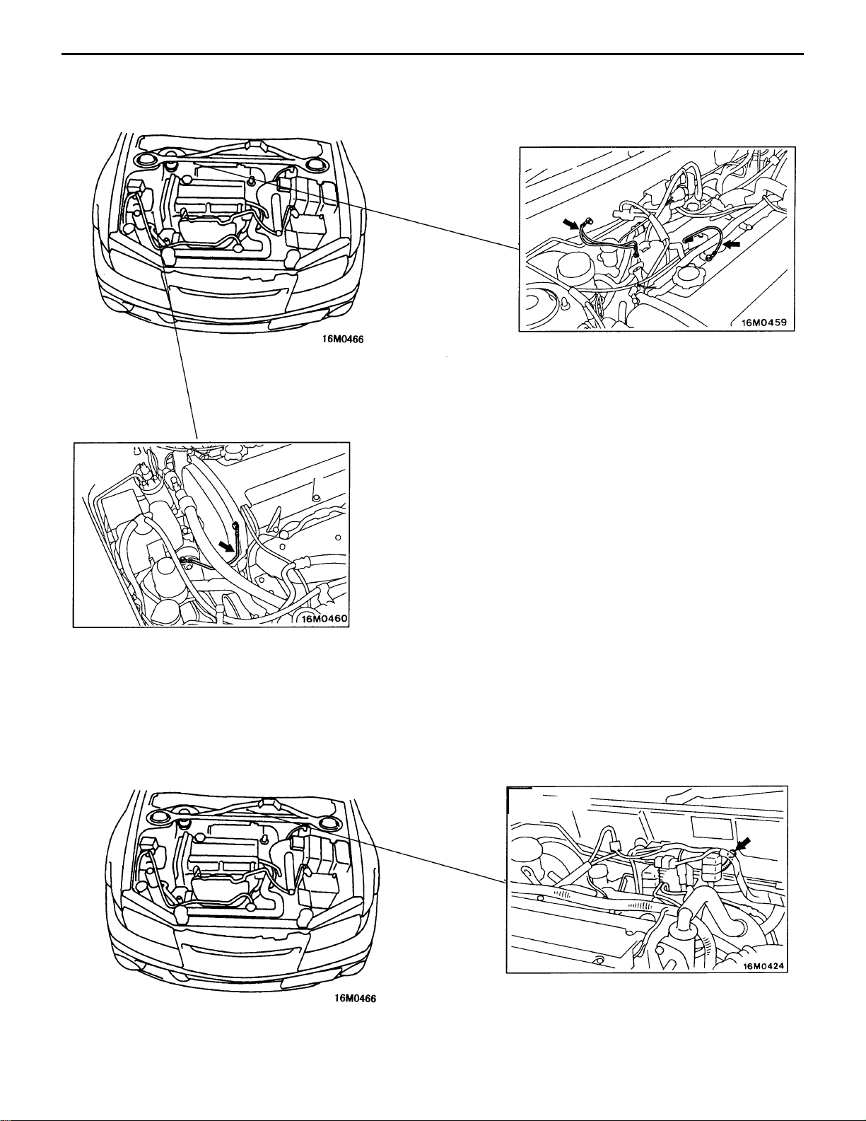
WIRING HARNESS CONFIGURATION DIAGRAMS
– Engine Compartment
WIRING HARNESS CONFIGURATION DIAGRAMS
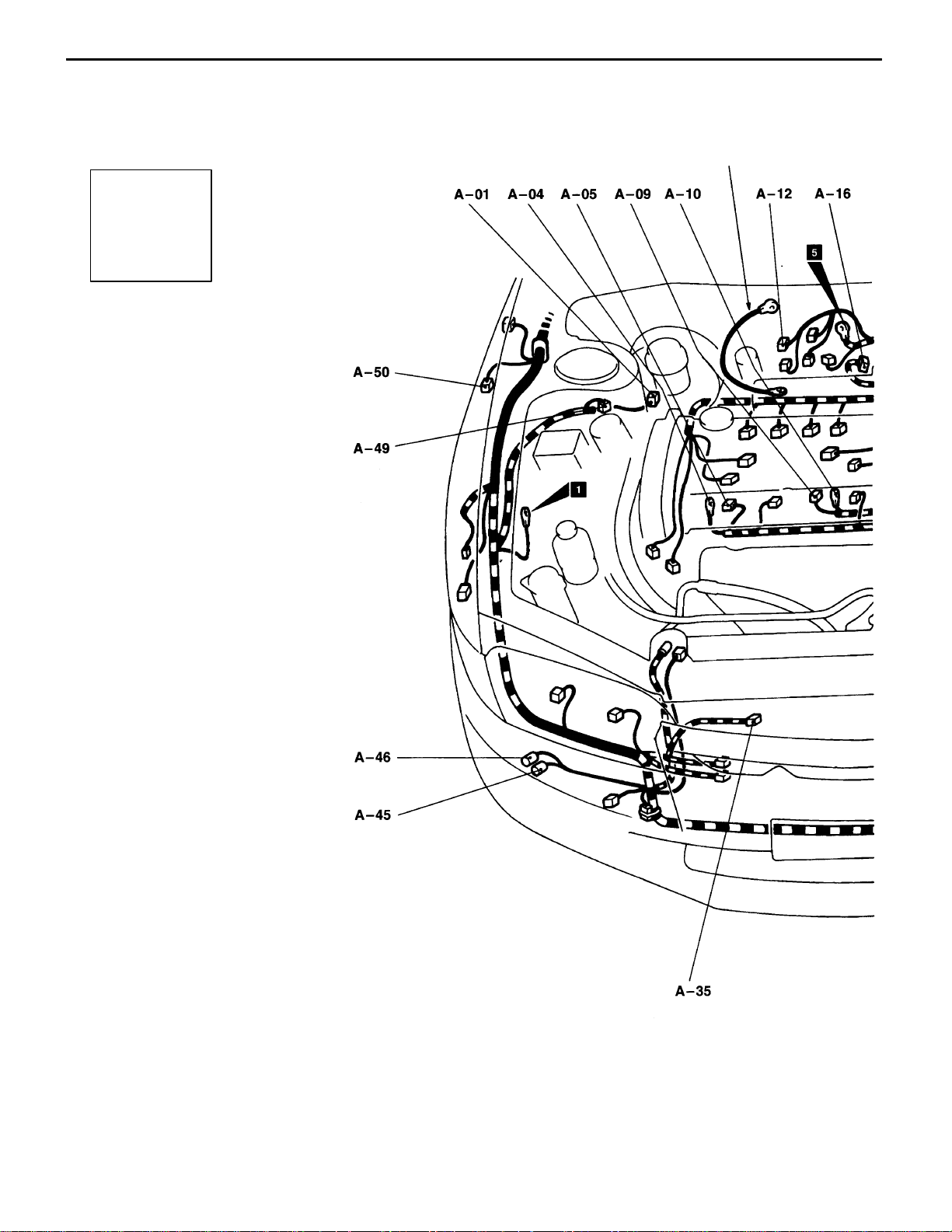
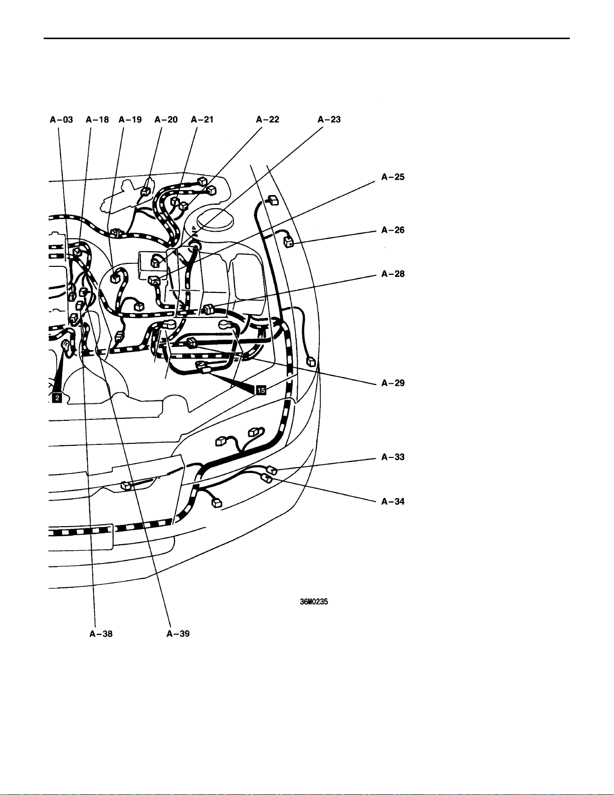
ENGINE COMPARTMENT
Connector
symbol
–01
A
thru
–50
Earth cable
A-01 (2-B) Brake fluid level switch
A-03 (1-B) Noise condenser
A-04 (1) Alternator
A-05 (4-GR) Alternator
A-09 (1-B) Starter
A-10 (1) Starter
A-12 (2-B) Fuel pressure solenoid valve
A-16 (4-B) Throttle position sensor
A-18 (6-B) Idle speed control servo
A-19 (3-B) Vehicle speed sensor
A-20 (4-B) Windshield wiper motor
A-21 (8-B) Hydraulic unit <vehicles with ABS>
A-22 (2-B) Hydraulic unit <vehicles with ABS>
A-23 (2-B) Waste gate solenoid valve
A-25 (7-B) Air flow sensor
A-26 (2-B) Front speed sensor (LH) <vehicles with
ABS>
A-28 (10-B) Control harness and front harness
combination
Page 5
WIRING HARNESS
CONFIGURATION DIAGRAMS
– Engine Compartment
C-5
A-29 (2-B) Front harness and battery harness
combination
A-33 (1) Horn (LH)
A-34 (1) Horn (LH)
A-35 (2-BR) Outside air temperature sensor <vehicles
with fully automatic air conditioner>
A-38 (2-B) Engine coolant temperature sensor
A-39 (1-B) Engine coolant temperature gauge unit
A-45 (1) Horn (RH)
A-46 (1) Horn (RH)
A-49 (2-BR) Dual pressure switch
A-50 (2-B) Front speed sensor (RH) <vehicles with
ABS>
Page 6
C-6
WIRING HARNESS
CONFIGURATION DIAGRAMS
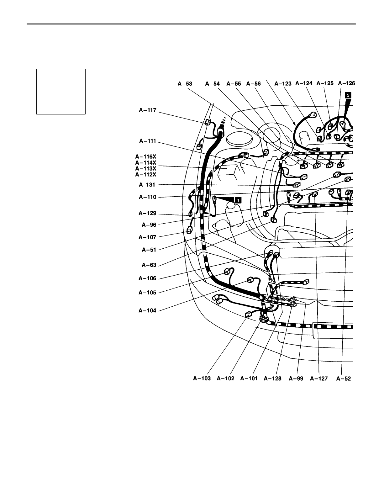
ENGINE COMPARTMENT
– Engine Compartment
Connector
symbol
–51
A
thru
–131
Earth cable
A-51 (3-B) Crank angle sensor
A-52 (1-B) Oil pressure switch
A-53 (2-B) Injector (No.1)
A-54 (2-B) Injector (No.2)
A-55 (2-B) Injector (No.3)
A-56 (2-B) Injector (No.4)
A-63 (4-B) O2 sensor
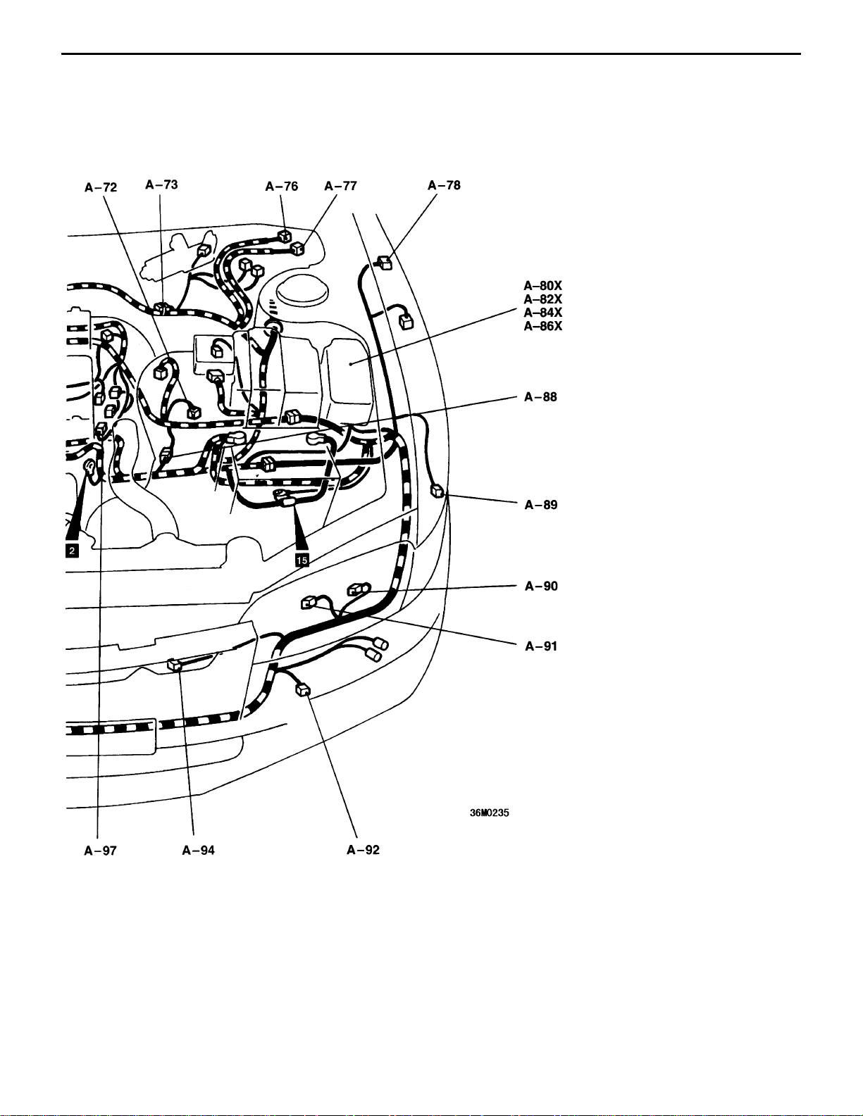
A-72 (2-B) Back-up lamp switch
A-73 (1-L) Engine speed detection connector
A-76 (6) Valve relay <vehicles with ABS>
A-77 (5) Motor relay <vehicles with ABS>
A-78 (2-GR) Side turn signal lamp (LH)
A-80X (5) Horn relay <vehicles with SRS air bag>
A-82X (5) Radiator fan relay (LO)
A-84X (5) Headlamp relay
A-86X (4) Alternator relay
A-88 (6-B) Control harness and battery harness
combination
A-89 (2-BR) Front turn signal lamp (LH)
A-90 (3-B) Headlamp (LH)
A-91 (2) Position lamp (LH)
A-92 (2-B) Fog lamp (LH)
Page 7
WIRING HARNESS
CONFIGURATION DIAGRAMS
– Engine Compartment
C-7
A-94 (4-GR) Radiator fan motor
A-96 (2-GR) Knock sensor
A-97 (3-B) Camshaft position sensor
A-99 (2-B) Condenser fan motor
A-101 (1) Power steering oil pressure switch
A-102 (1) Spare connector for fog lamp
A-103 (2-B) Fog lamp (RH)
A-104 (2) Position lamp (RH)
A-105 (3-B) Headlamp (RH)
A-106 (1-B) A/C compressor assembly
A-107 (2-BR) Front turn signal lamp (RH)
A-1 10 (3-GR) Ignition coil 1
A-1 11 (3-GR) Ignition coil 2
A-112X (4) Radiator fan relay (HI)
A-113X (4) Condenser fan relay (LO)
A-114X (4) Condenser fan relay (HI)
A-116X (4) A/C compressor relay
A-117 (2-GR) Side turn signal lamp (RH)
A-123 (5-B) Fuel pump relay No.2
A-124 (2-B) Fuel pump resistor
A-125 (6-B) Resistor (for injector)
A-126 (5-B) AYC relay
A-127 (2-B) Secondary air control solenoid valve
A-128 (2-GR) Condenser fan motor
A-129 (2-B) Water spray motor
A-131 (1-B) Noise condenser
Page 8
C-8
DASH PANEL
Connector
symbol
B
WIRING HARNESS
CONFIGURATION DIAGRAMS
– Dash Panel
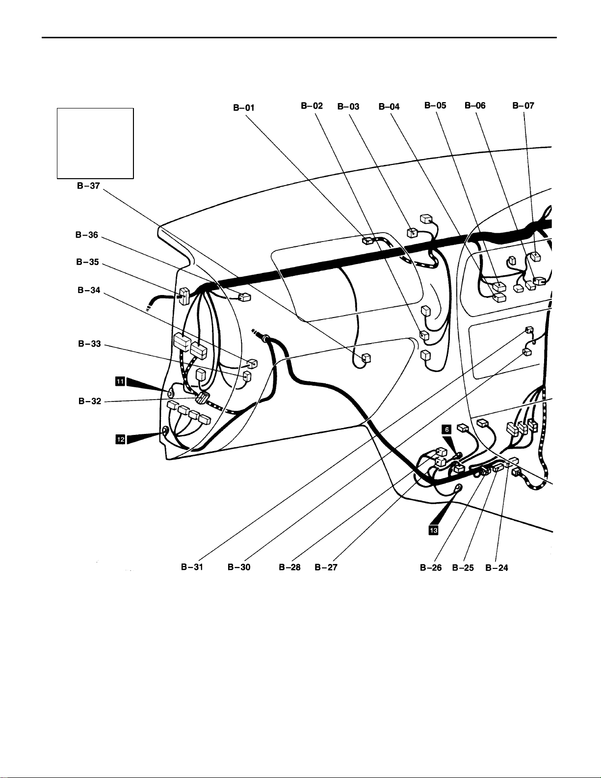
B-01 (2-R) Passenger seat air bag module (squib)
B-02 (2) Heater water temperature sensor <ve-
hicles with fully automatic air conditioner>
B-03 (2-B) Air thermo sensor <vehicles with fully
automatic air conditioner>
B-04 (20-B) A/C-ECU <vehicles with fully automatic
air conditioner>
B-05 (16-B) A/C-ECU <vehicles with fully automatic
air conditioner>
B-06 (6) Air outlet change-over damper motor and
potentiometer <vehicles with fully automatic air conditioner>
B-07 (8) Blower switch <vehicles with manual air
conditioner>
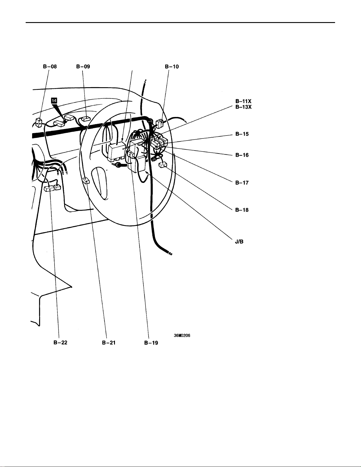
B-08 (25) Meter and gauge
B-09 (25) Meter and gauge
B-10 (22) Body harness and front door harness
(driver’s side) combination
B-11X (8) Rear intermittent wiper relay
B-13X (5) Power window relay
B-15 (20) Front harness and body harness
combination
B-16 (6) Front harness and body harness
combination
B-17 (14) Front harness and body harness
combination <ABS>
B-18 (19) J/C (1)
B-19 (22) Body harness and instrument panel
harness combination
Page 9
WIRING HARNESS
CONFIGURATION DIAGRAMS
Interior relay box
– Dash Panel
C-9
B-21 (2) Stop lamp switch
B-22 (16-B) Diagnosis connector
B-24 (26-Y) ABS-ECU
B-25 (22-Y) ABS-ECU
B-26 (2-B) Diode (for ABS circuit)
B-27 (4) Engine control relay
B-28 (4) Fuel pump relay
B-30 (14) Radio or spare connector for radio
B-31 (1) Glass antenna amplifier
B-32 (19-B) J/C (5)
B-33 (2) Blower motor <vehicles with fully auto-
matic air conditioner>
B-34 (4) Blower high speed relay <vehicles with
fully automatic air conditioner>
B-35 (22) Body harness and front door harness
(passenger’s side) combination
B-36 (2) Inside and outside air change-over
damper motor <vehicles with fully
automatic air conditioner>
B-37 (4) Power transistor <vehicles with fully
automatic air conditioner> or resistor
<vehicles with heater or manual air
conditioner>
Page 10
C-10
DASH PANEL
Connector
symbol
B
WIRING HARNESS
CONFIGURATION DIAGRAMS
– Dash Panel
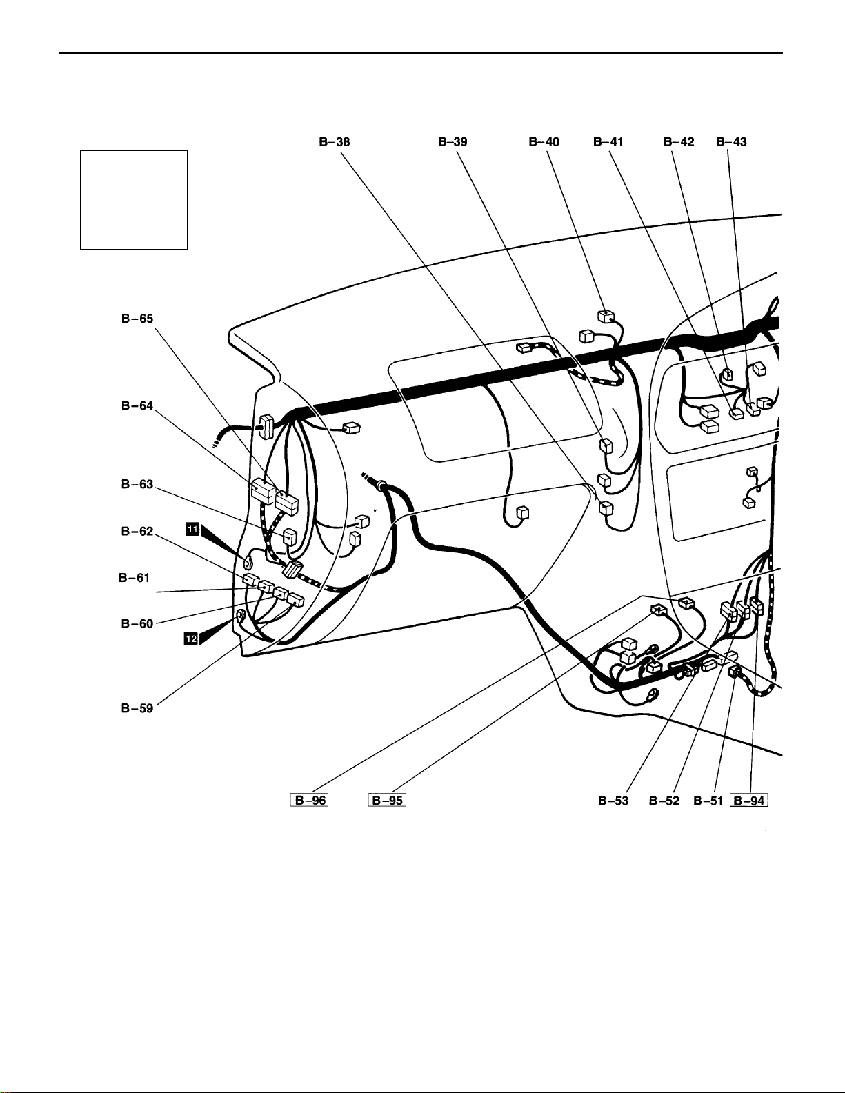
B-38 (2) Sunlight sensor <vehicles with fully
automatic air conditioner>
B-39 (6) Air mix damper motor and potentiometer
<vehicles with fully automatic air conditioner>
B-40 (3) Automatic compressor ECU
<vehicles with manual air conditioner>
B-41 (8) A/C switch
<vehicles with manual air conditioner>
B-42 (2) Blower switch illumination lamp <vehicles
with heater or manual air conditioner>
B-43 (6-B) Defogger switch <vehicles with heater or
manual air conditioner>
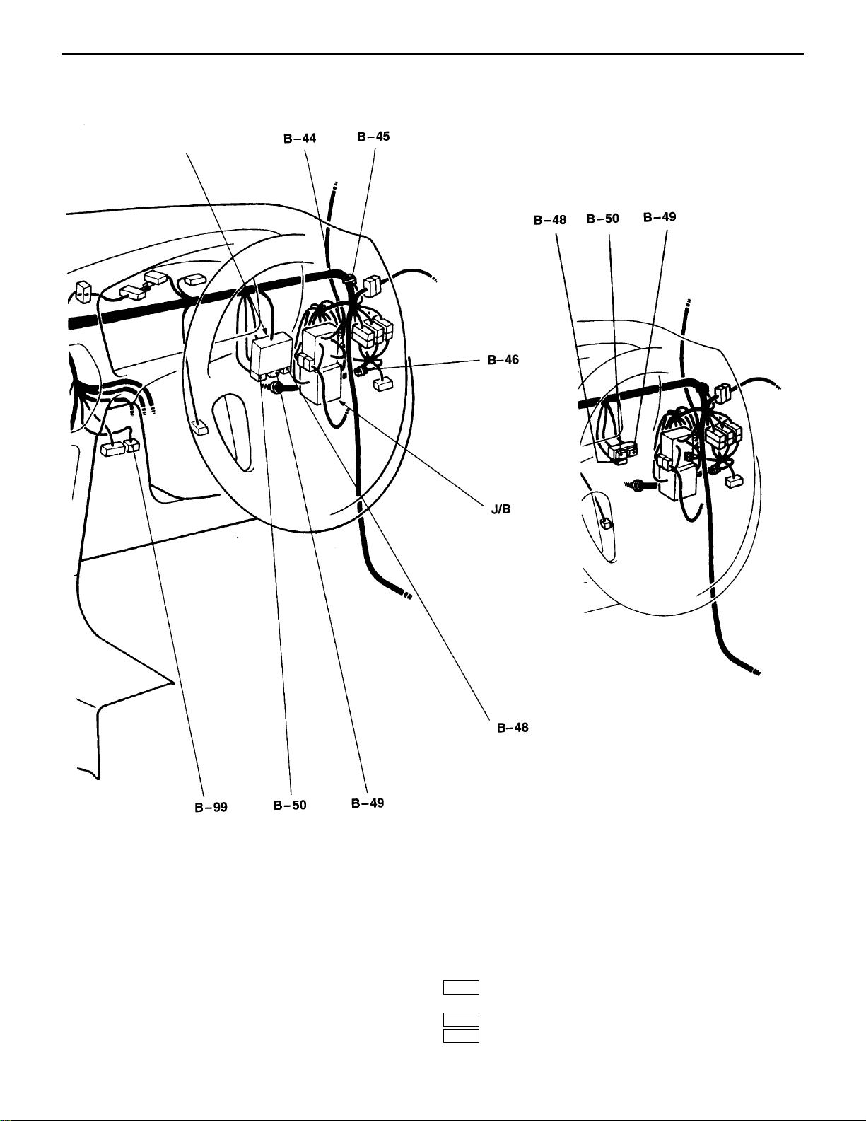
B-44 (6) Body harness and roof harness combina-
tion <vehicles with sunroof>
B-45 (2-B) Diode (for keyless entry system circuit)
B-46 (2) Spare connector for fog lamp switch
<vehicles without fog lamp>
B-48 (14) J/C (2)
B-49 (14) J/C (3)
B-50 (14-L) J/C (4)
B-51 (21-Y) SRS-ECU
B-52 (16-B) Control harness and body harness
combination <vehicles with ABS>
Page 11
WIRING HARNESS
CONFIGURATION DIAGRAMS
– Dash Panel
C-11
Interior relay box
<Vehicles without interior relay box>
B-59 (26-Y) Engine-ECU
B-60 (16-Y) Engine-ECU
B-61 (12-Y) Engine-ECU
B-62 (22-Y) Engine-ECU
B-63 (2) Blower motor <vehicles with heater or
manual air conditioner>
B-64 (13) Control harness and body harness
combination
NOTE
The connectors with framed
number are newly introduced.
B-65 (16-B) Control harness and body harness
combination
B-94 (13) Control harness and body harness
combination <vehicles with AYC-ECU>
B-95 (26) AYC-ECU
B-96 (16) AYC-ECU
B-99 (12) Diagnosis connector
Page 12
C-12
WIRING HARNESS
CONFIGURATION DIAGRAMS
FLOOR AND ROOF
Connector
symbol
D
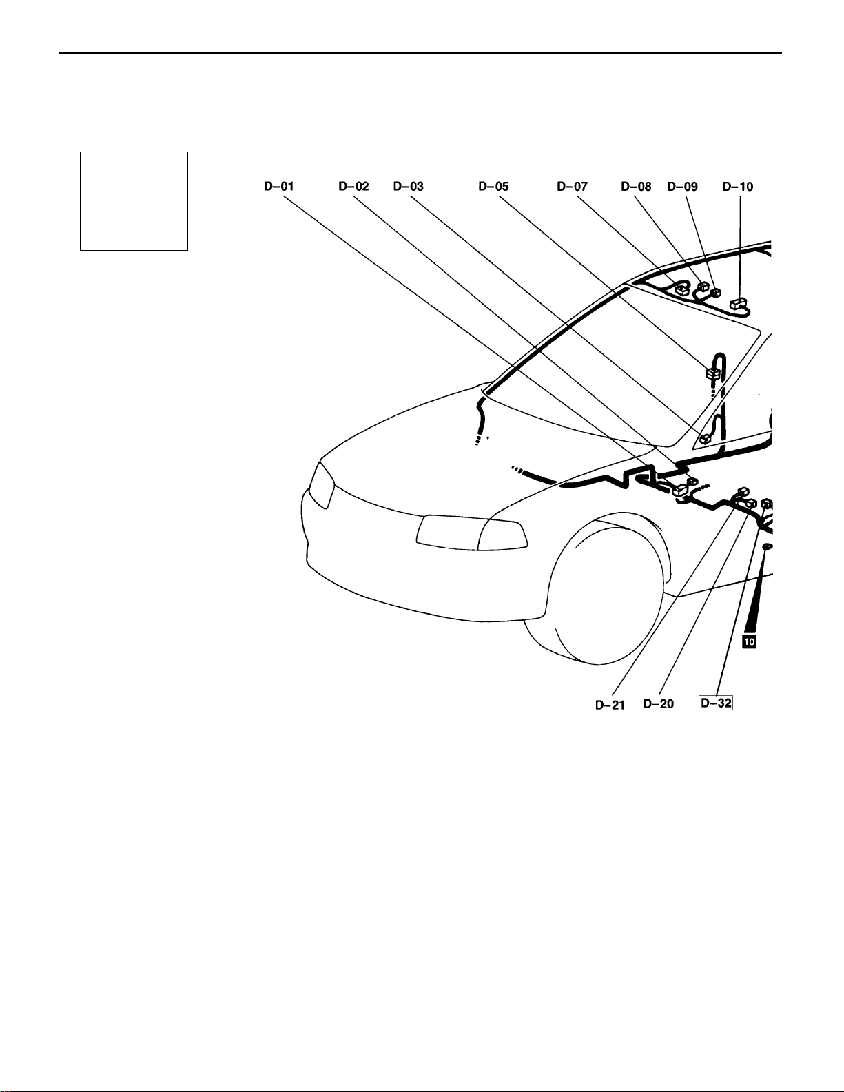
– Floor and Roof
D-01 (20) Receiver
<vehicles with keyless entry system>
D-02 (2) Seat belt switch
D-03 (2) Front door switch (driver’s side)
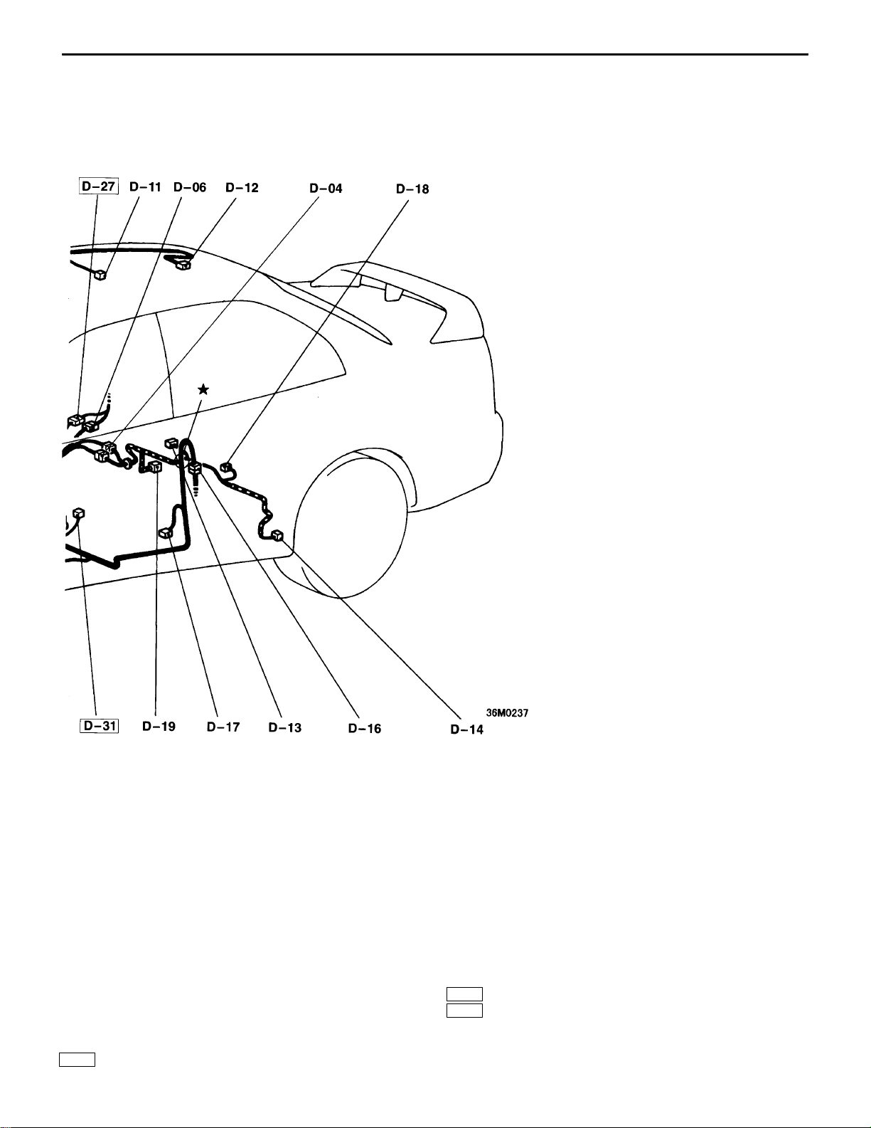
D-04 (10) Body harness and fuel harness combina-
tion
D-05 (6) Body harness and rear door harness
(RH) combination
D-06 (18) Body harness and rear harness combina-
tion
D-07 (6) Sunroof switch
D-08 (2) Room lamp <vehicles with sunroof>
D-09 (1) Map lamp
D-10 (18) Sunroof ECU
D-11 (2-GR) Room lamp <vehicles without sunroof>
D-12 (8) Sunroof motor
D-13 (3-B) Fuel gauge unit (sub)
D-14 (2-B) Rear speed sensor (LH)
<vehicles with ABS>
D-16 (6) Body harness and rear door harness (LH)
combination
D-17 (2) Front door switch (passenger’s side)
D-18 (6) Fuel gauge unit (main)
Page 13
WIRING HARNESS
CONFIGURATION DIAGRAMS
– Floor and Roof
C-13
D-19 (2-B) Rear speed sensor (RH)
<vehicles with ABS>
D-20 (3-B) Acceleration sensor <vehicles with ABS>
D-21 (1-B) Parking brake switch
D-27 (2) Body harness and rear harness combina-
tion <vehicles with AYC>
NOTE
The connectors with framed
number are newly introduced.
D-31 (2) Water spray switch
D-32 (3-B) Acceleration sensor (lateral)
<vehicles with AYC>
Page 14
C-14
WIRING HARNESS
CONFIGURATION DIAGRAMS
LUGGAGE COMPARTMENT
Connector
symbol
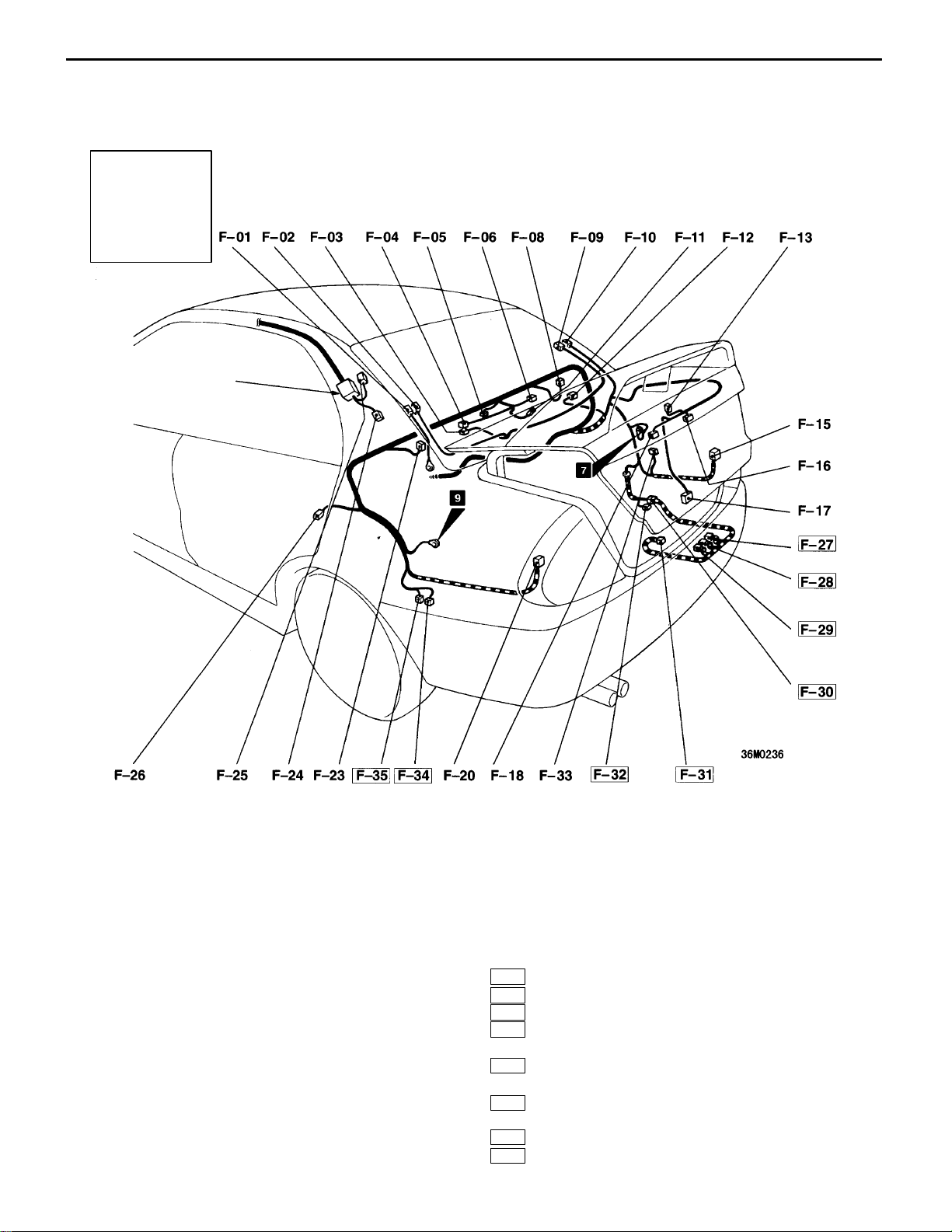
F
Glass
antenna
amplifier
– Luggage Compartment
NOTE
The connectors with framed
number are newly introduced.
F-01 (1-B) Defogger (–) <vehicles without choke coil>
F-02 (1-B) Defogger (–) <vehicles with choke coil>
F-03 (2) Choke coil
F-04 (3) Choke coil
F-05 (2) Trunk room lamp
F-06 (2) Vacant connector or high mounted stop
lamp (installed on rear shelf)
F-08 (2-B) Rear speaker (RH)
F-09 (1-B) Defogger (+) <vehicles with choke coil>
F-10 (1-B) Defogger (+) <vehicles without choke coil>
F-11 (3) Rear wiper motor
F-12 (1-B) Rear door switch (RH)
F-13 (2) High mounted stop lamp (installed on rear
spoiler)
F-15 (6) Rear combination lamp (RH)
F-16 (2-GR) Licence plate lamp (RH)
F-17 (1-B) Trunk room lamp switch
F-18 (2-GR) Licence plate lamp (LH)
F-20 (6) Rear combination lamp (LH)
F-23 (2-B) Rear speaker (LH)
F-24 (1) Glass antenna
<vehicles with diversity glass antenna>
F-25 (1) Glass antenna
F-26 (1-B) Rear door switch (LH)
F-27 (3-B) Proportioning valve <vehicles with AYC>
F-28 (2-B) Direction valve (LH) <vehicles with AYC>
F-29 (2-B) Direction valve (RH) <vehicles with A YC>
F-30 (8-B) Rear harness and A YC harness combina-
tion
F-31 (2-B) Accumulator pressure switch
<vehicles with AYC>
F-32 (2-B) AYC motor
F-33 (6) CD changer
F-34 (2) Rear window washer
F-35 (2) Windshield washer motor
Page 15
C-16
SINGLE PART INSTALLATION POSITION – Relay
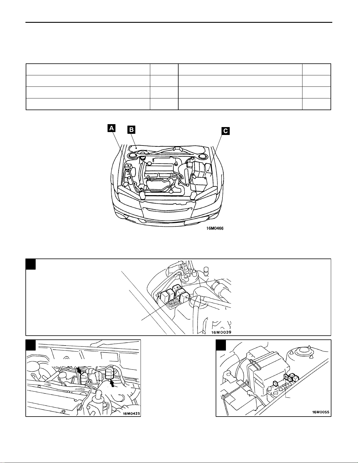
SINGLE PART INSTALLATION POSITION
RELAY
Name Symbol Name Symbol
AYC relay B Fuel pump relay No.2 B
Condenser fan motor relay (HI) A Radiator fan motor relay (HI) A
Condenser fan motor relay (LO) A Radiator fan motor relay (LO) C
A
Condenser fan motor
relay (LO)
B
Fuel pump relay No.2
A YC relay
Condenser fan motor
relay (HI)
Radiator fan motor
relay (HI)
C
Radiator fan
motor relay (LO)
Page 16
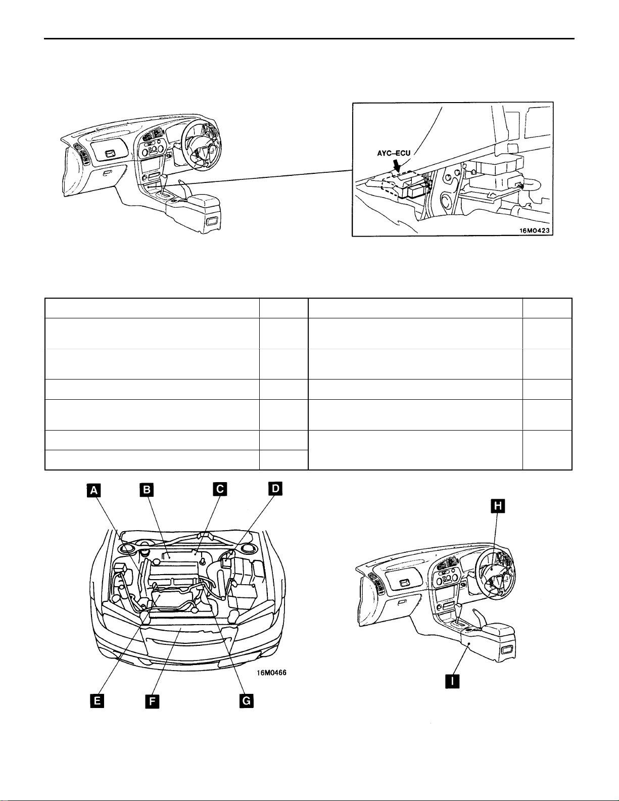
SINGLE PART INSTALLATION POSITION – ECU / Sensor
C-17
ECU
B21A066
SENSOR
Name Symbol Name Symbol
Acceleration sensor (lateral) <vehicles with
AYC>
Acceleration sensor (longitudinal) <vehicles
with ABS and AYC>
Air flow sensor D O2 sensor E
Camshaft position sensor G Steering angle sensor (lateral) <vehicles with
Crank angle sensor A Throttle position sensor C
Engine coolant temperature sensor G
I Knock sensor B
I Outside air temperature sensor <vehicles with
fully automatic air conditioner>
AYC>
F
H
B21A066
Page 17
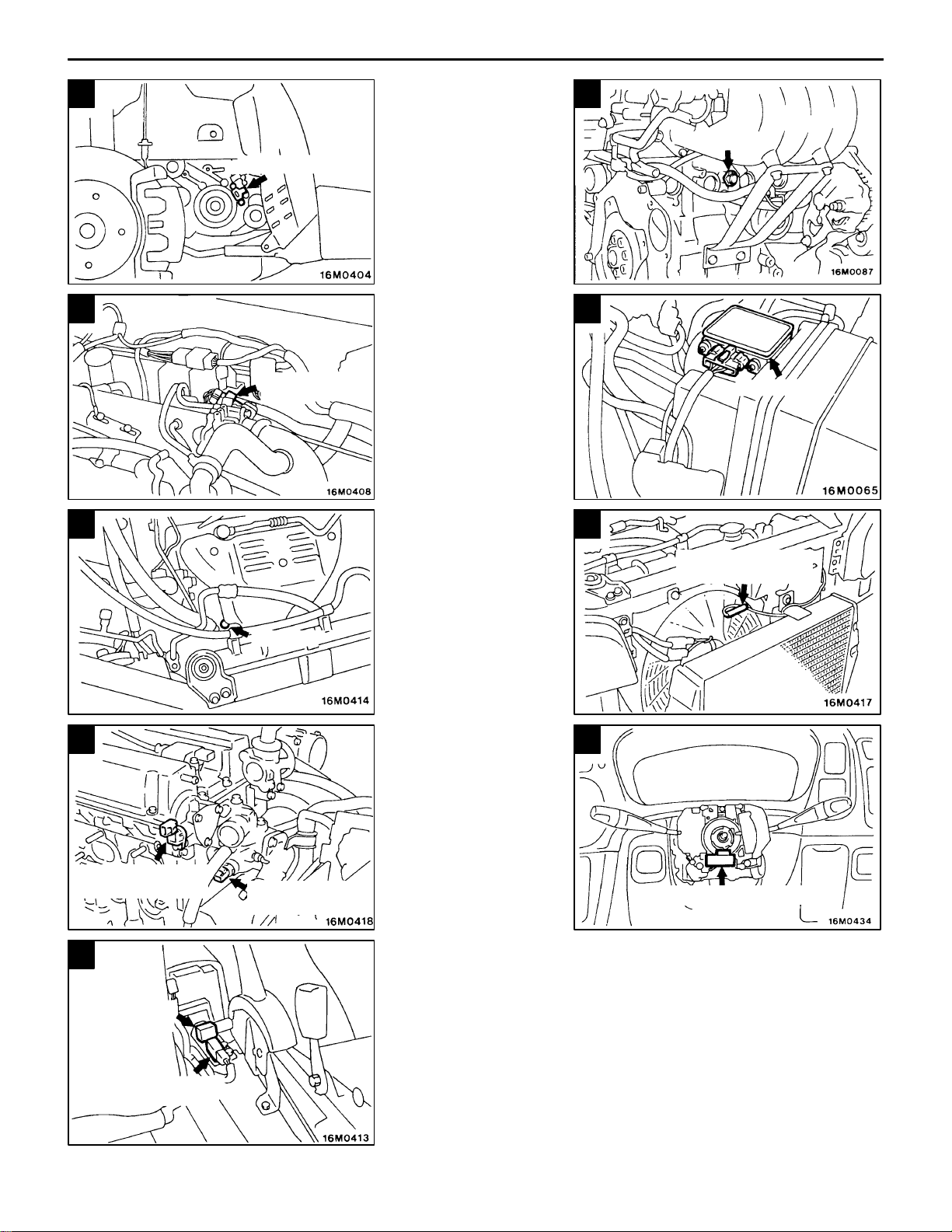
C-18
SINGLE PART INSTALLATION POSITION – Sensor
A
Crank angle sensor
C
Throttle position
sensor
E
B
Knock sensor
D
Air flow sensor
F
G
Camshaft position
sensor
I
Acceleration
sensor
(longitudinal)
O2 sensor
Engine coolant
temperature sensor
Outside air
temperature sensor
H
Steering angle sensor
Acceleration sensor
(lateral)
Page 18
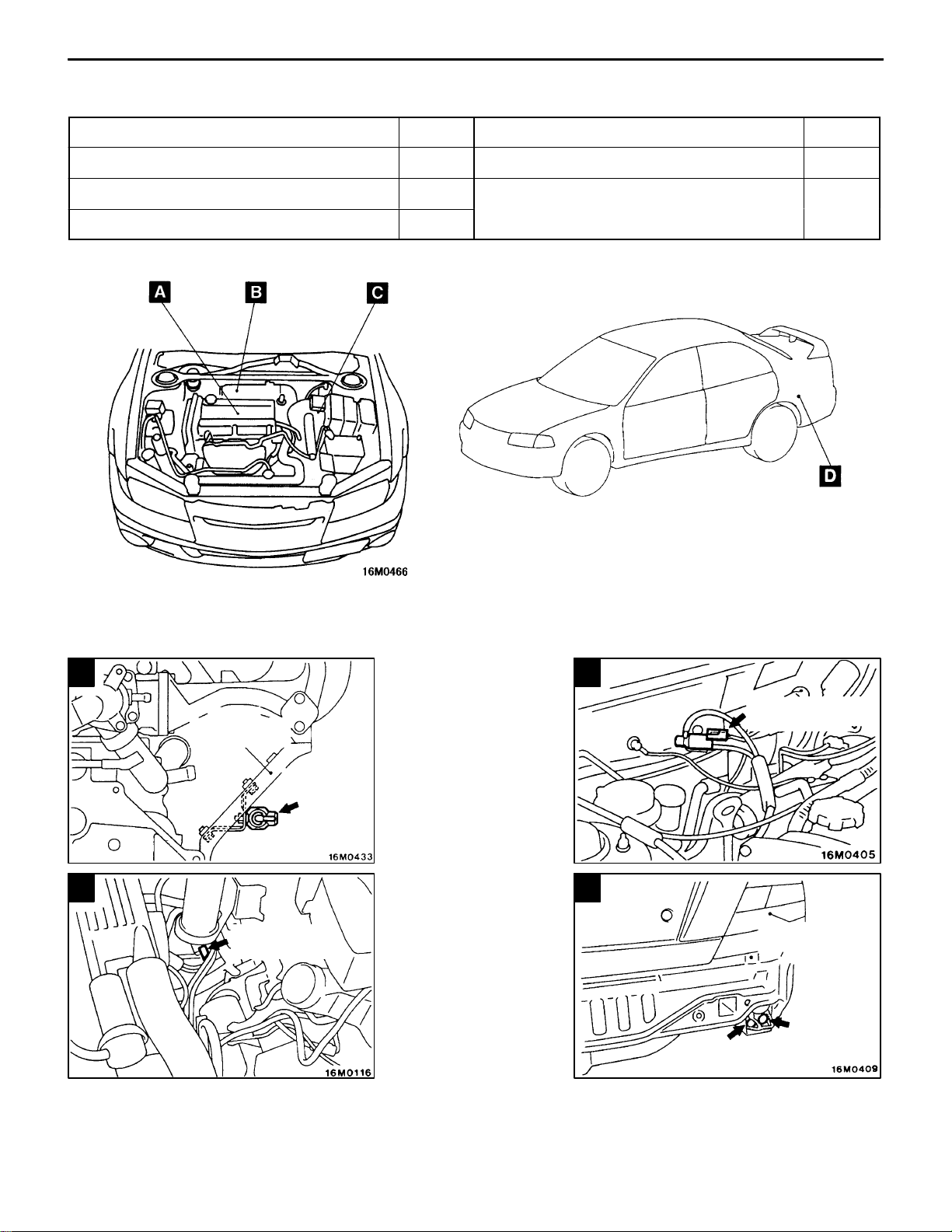
SINGLE PART INSTALLATION POSITION – Solenoid and Solenoid Valve
C-19
SOLENOID AND SOLENOID VALVE
Name Symbol Name Symbol
Direction valve <vehicles with AYC> D Secondary air control solenoid valve A
Fuel pressure solenoid valve B Waste gate solenoid valve C
Proportioning valve <vehicles with AYC> D
DOM0011
A
Intake manifold
stay
Secondary
air control
solenoid
valve
C
Waste gate
solenoid valve
B
Fuel pressure
solenoid valve
D
Rear combination
lamp (RH)
Direction valve
Proportioning
valve
Page 19
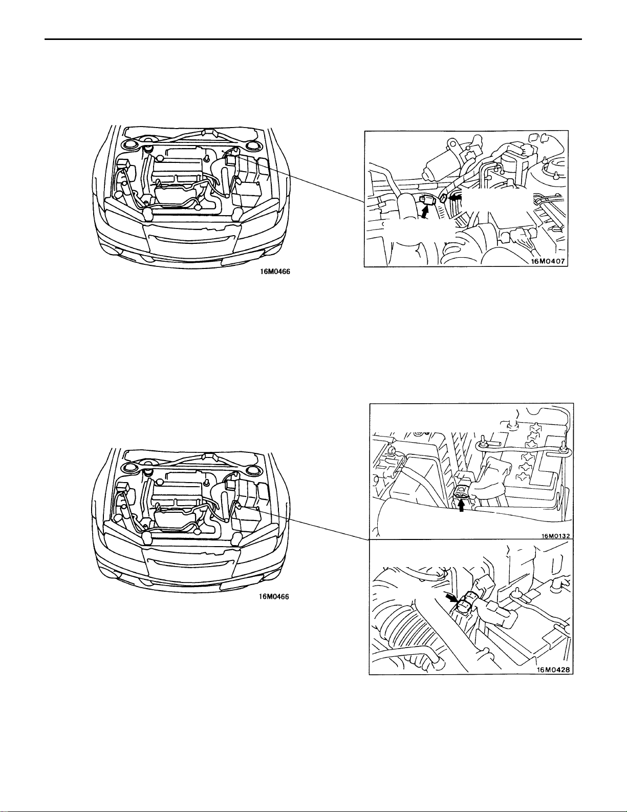
C-20
SINGLE PART
INSTALLATION POSITION
INSPECTION CONNECTOR
Inspection Connector / Fusible Link and
–
Fuse
Engine speed
check connector
Fuel pump
check connector
FUSIBLE LINK AND FUSE
<Vehicles with AYC
(vehicles without ABS)>
Fusible link
<Vehicles with AYC
(vehicles with ABS)>
Fusible link
Page 20
SINGLE PART INSTALLATION POSITION – Earth Cable / Earth
EARTH CABLE
C-21
EARTH
Page 21
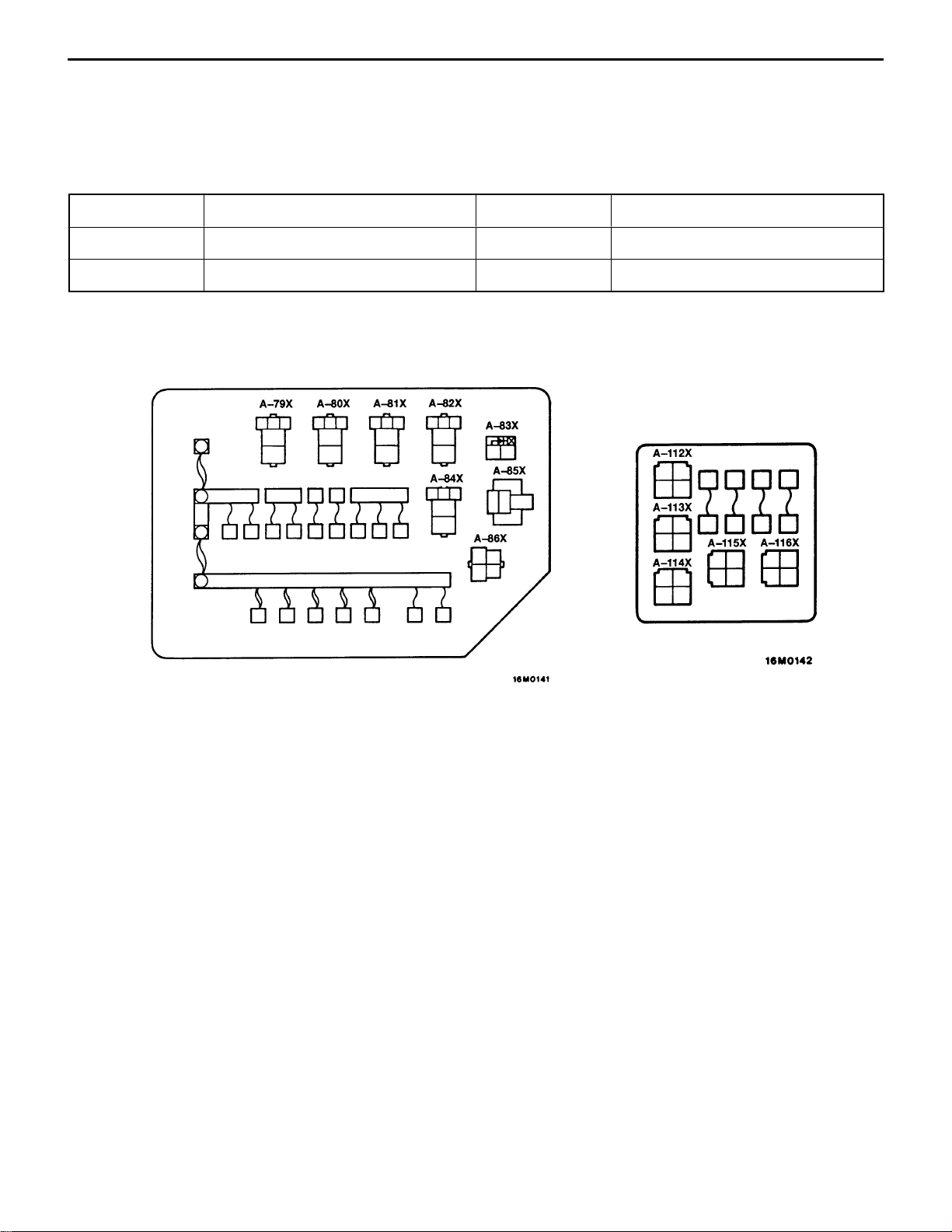
CIRCUIT DIAGRAM – Centralized Junction
CIRCUIT DIAGRAM
CENTRALIZED JUNCTION
CENTRALIZED RELAY
Connector No. Name Connector No. Name
A-82X Radiator fan motor relay (LO) A-113X Condenser fan motor relay (LO)
A-112X Radiator fan motor relay (HI) A-114X Condenser fan motor relay (HI)
Relay box in engine compartment
(A/C relay box)
C-23
Page 22

C-24
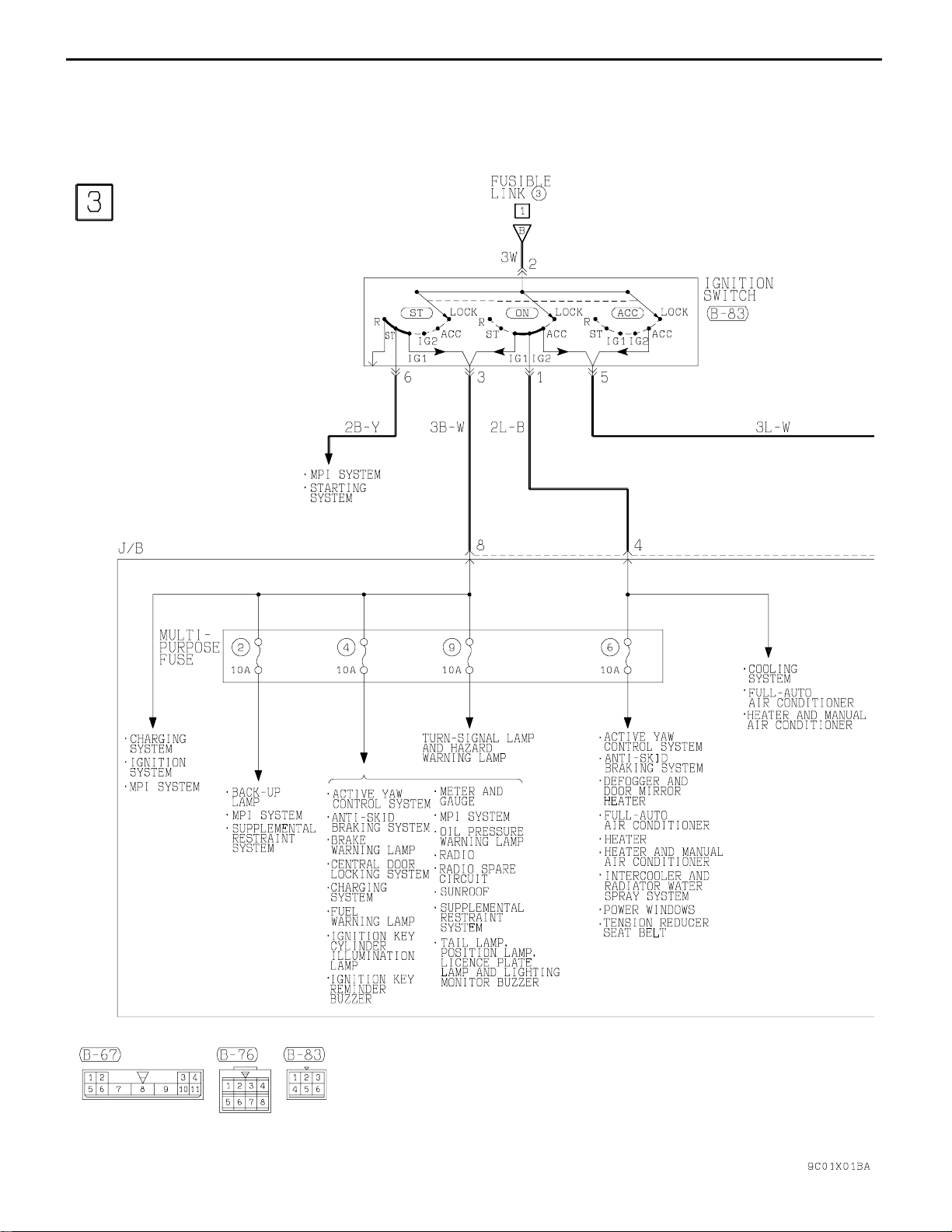
CIRCUIT DIAGRAM – Power Distribution System
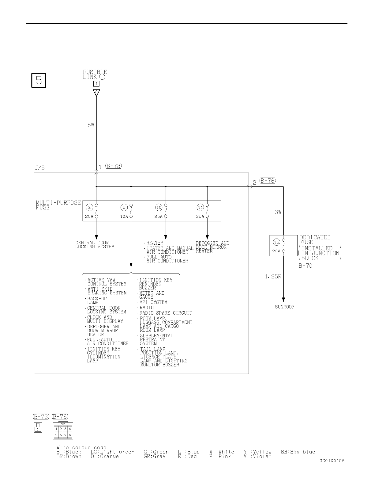
POWER DISTRIBUTION SYSTEM
Page 23

CIRCUIT DIAGRAM – Power Distribution System
C-25
Page 24
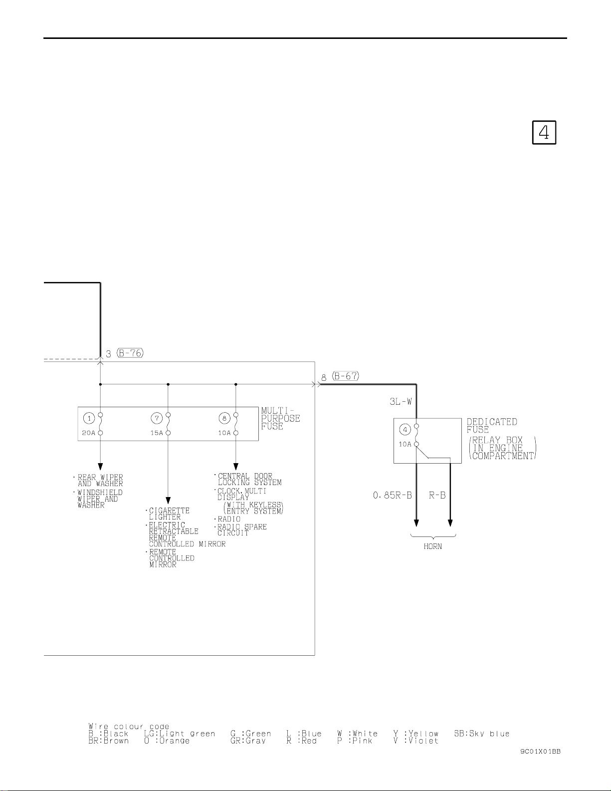
C-26
POWER DISTRIBUTION SYSTEM (CONTINUED)
CIRCUIT DIAGRAM – Power Distribution System
Page 25
CIRCUIT DIAGRAM – Power Distribution System
C-27
Page 26
C-28
POWER DISTRIBUTION SYSTEM (CONTINUED)
CIRCUIT DIAGRAM – Power Distribution System
Page 27
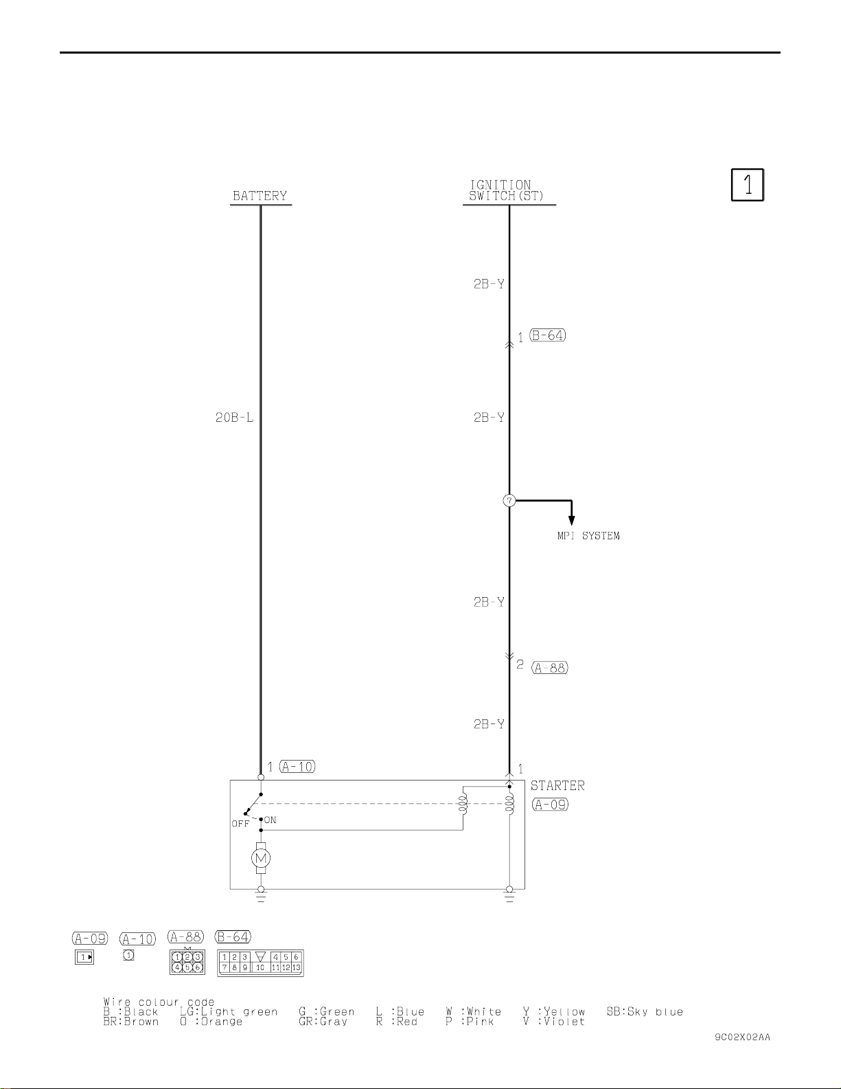
CIRCUIT DIAGRAM – Starting System
STARTING SYSTEM
C-29
Page 28
C-30
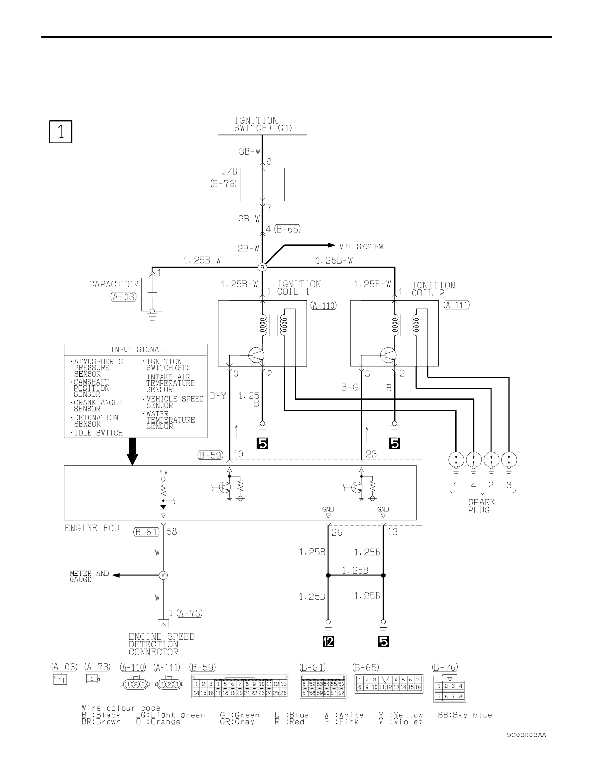
IGNITION SYSTEM
CIRCUIT DIAGRAM – Ignition System
Page 29
CIRCUIT DIAGRAM – Charging System
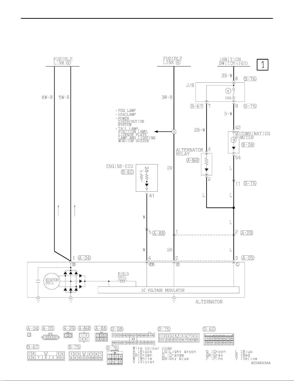
CHARGING SYSTEM
C-31
Page 30

C-32
MPI SYSTEM
CIRCUIT DIAGRAM – MPI System
Page 31

CIRCUIT DIAGRAM – MPI System
C-33
Page 32

C-34
MPI SYSTEM (CONTINUED)
CIRCUIT DIAGRAM – MPI System
Page 33

CIRCUIT DIAGRAM – MPI System
C-35
Page 34

C-36
MPI SYSTEM (CONTINUED)
CIRCUIT DIAGRAM – MPI System
Page 35

CIRCUIT DIAGRAM – MPI System
C-37
Page 36

C-38
COOLING SYSTEM
CIRCUIT DIAGRAM – Cooling System
Page 37

CIRCUIT DIAGRAM – Cooling System
C-39
Page 38

C-40
HEADLAMP
CIRCUIT DIAGRAM – Headlamp
Page 39

C-42
CIRCUIT DIAGRAMS –
Tail lamp, Position Lamp, Licence Plate Lamp and Lighting Monitor Buzzer
TAIL LAMP, POSITION LAMP, LICENCE PLATE LAMP AND LIGHTING
MONITOR BUZZER
Page 40

CIRCUIT DIAGRAMS –
Tail lamp, Position Lamp, Licence Plate
Lamp and Lighting Monitor Buzzer
C-43
Page 41

C-44
CIRCUIT DIAGRAMS –
Tail lamp, Position Lamp, Licence Plate
Lamp and Lighting Monitor Buzzer
TAIL LAMP, POSITION LAMP, LICENCE PLATE LAMP AND LIGHTING MONITOR
BUZZER (CONTINUED)
Page 42

Room Lamp and Luggage
CIRCUIT DIAGRAMS –
Compartment Lamp
ROOM LAMP AND LUGGAGE COMPARTMENT LAMP
C-45
Page 43

C-46
CIRCUIT DIAGRAM – Ignition Key Cylinder Illumination Lamp
IGNITION KEY CYLINDER ILLUMINATION LAMP
Page 44

C-48
CIRCUIT DIAGRAMS –
Turn-Signal Lamp and Hazard Warning Lamp
TURN-SIGNAL LAMP AND HAZARD WARNING LAMP
Page 45

CIRCUIT DIAGRAMS –
Turn-Signal Lamp and Hazard
Warning Lamp
C-49
Page 46

C-50
CIRCUIT DIAGRAMS –
Turn-Signal Lamp and Hazard
Warning Lamp
TURN-SIGNAL LAMP AND HAZARD WARNING LAMP (CONTINUED)
Page 47

STOP LAMP
CIRCUIT DIAGRAM – Stop Lamp
C-51
Page 48

C-52
BACK-UP LAMP
CIRCUIT DIAGRAM – Back-up Lamp
Page 49

C-54
CIRCUIT DIAGRAM – Meter and Gauge
METER AND GAUGE
Page 50

CIRCUIT DIAGRAM – Meter and Gauge
C-55
Page 51

C-56
CIRCUIT DIAGRAMS –
Fuel Warning Lamp and Brake
Warning Lamp
FUEL WARNING LAMP AND BRAKE WARNING LAMP
Page 52

CIRCUIT DIAGRAMS –
Oil Pressure Warning Lamp and
Seat Belt Warning Lamp
C-57
OIL PRESSURE WARNING LAMP AND SEAT BELT WARNING LAMP
Page 53

C-58
CIRCUIT DIAGRAMS –
CENTRAL DOOR LOCKING SYSTEM
<WITHOUT KEYLESS ENTRY SYSTEM>
Central Door Locking System
<Without Keyless Entry System>
Page 54

CIRCUIT DIAGRAMS –
Central Door Locking System
<Without Keyless Entry System>
C-59
Page 55

C-60
CIRCUIT DIAGRAMS –
CENTRAL DOOR LOCKING SYSTEM
<WITH KEYLESS ENTRY SYSTEM>
Central Door Locking System
<With Keyless Entry System>
Page 56

CIRCUIT DIAGRAMS –
Central Door Locking System
<With Keyless Entry System>
C-61
Page 57

C-62
CIRCUIT DIAGRAMS –
Central Door Locking System
<With Keyless Entry System>
CENTRAL DOOR LOCKING SYSTEM <WITH KEYLESS ENTRY SYSTEM>
(CONTINUED)
Page 58

CIRCUIT DIAGRAMS –
Central Door Locking System
<With Keyless Entry System>
C-63
Page 59

C-64
CIRCUIT DIAGRAM – Heater and Air Conditioner
HEATER AND AIR CONDITIONER
Page 60

CIRCUIT DIAGRAM – Heater and Air Conditioner
C-65
Page 61

C-66
HEATER AND AIR CONDITIONER (CONTINUED)
CIRCUIT DIAGRAM – Heater and Air Conditioner
Page 62

CIRCUIT DIAGRAM – Heater and Air Conditioner
C-67
Page 63

C-68
HEATER AND AIR CONDITIONER (CONTINUED)
CIRCUIT DIAGRAM – Heater and Air Conditioner
Page 64

C-70
CIRCUIT DIAGRAM – Full-auto Air Conditioner
FULL-AUTO AIR CONDITIONER
Page 65

CIRCUIT DIAGRAM – Full-auto Air Conditioner
C-71
Page 66

C-72
FULL-AUTO AIR CONDITIONER (CONTINUED)
CIRCUIT DIAGRAM – Full-auto Air Conditioner
Page 67

CIRCUIT DIAGRAM – Full-auto Air Conditioner
C-73
Page 68

C-74
FULL-AUTO AIR CONDITIONER (CONTINUED)
CIRCUIT DIAGRAM – Full-auto Air Conditioner
Page 69

CIRCUIT DIAGRAM – Full-auto Air Conditioner
C-75
Page 70

C-76
FULL-AUTO AIR CONDITIONER (CONTINUED)
CIRCUIT DIAGRAM – Full-auto Air Conditioner
Page 71

C-78
CIRCUIT DIAGRAM – Windshield Wiper and Washer <With Intermittent Wiper>
WINDSHIELD WIPER AND WASHER <WITH INTERMITTENT WIPER>
Page 72

CIRCUIT DIAGRAM – Rear Wiper and Washer
REAR WIPER AND WASHER
C-79
Page 73

C-80
CIRCUIT DIAGRAMS –
Defogger and Door Mirror Heater
<Without Full-auto Air Conditioner>
DEFOGGER AND DOOR MIRROR HEATER <WITHOUT FULL-AUTO
AIR CONDITIONER>
Page 74

CIRCUIT DIAGRAMS –
Defogger and Door Mirror Heater
<Without Full-auto Air Conditioner>
C-81
Page 75

C-82
CIRCUIT DIAGRAMS –
Defogger and Door Mirror Heater
<With Full-auto Air Conditioner>
DEFOGGER AND DOOR MIRROR HEATER <WITH FULL-AUTO AIR
CONDITIONER>
Page 76

CIRCUIT DIAGRAMS –
Defogger and Door Mirror Heater
<With Full-auto Air Conditioner>
C-83
Page 77

C-84
CIRCUIT DIAGRAM – Radio <Radio Spare Circuit>
RADIO <RADIO SPARE CIRCUIT>
Page 78

CIRCUIT DIAGRAM – Radio <Radio Spare Circuit>
C-85
Page 79

C-86
CIRCUIT DIAGRAM – Radio <4 Speaker, 6 Speaker>
RADIO <4 SPEAKER, 6 SPEAKER>
Page 80

CIRCUIT DIAGRAM – Radio <4 Speaker, 6 Speaker>
C-87
Page 81

C-88
RADIO <4 SPEAKER, 6 SPEAKER> (CONTINUED)
CIRCUIT DIAGRAM – Radio <4 Speaker, 6 Speaker>
Page 82

CIRCUIT DIAGRAM – Key Reminder Buzzer
KEY REMINDER BUZZER
C-89
Page 83

C-90
CIRCUIT DIAGRAM – Anti-skid Braking System (ABS)
ANTI-SKID BRAKING SYSTEM (ABS)
Page 84

CIRCUIT DIAGRAM – Anti-skid Braking System (ABS)
C-91
Page 85

C-92
ANTI-SKID BRAKING SYSTEM (ABS) (CONTINUED)
CIRCUIT DIAGRAM – Anti-skid Braking System (ABS)
Page 86

CIRCUIT DIAGRAM – Anti-skid Braking System (ABS)
C-93
Page 87

C-94
ANTI-SKID BRAKING SYSTEM (ABS) (CONTINUED)
CIRCUIT DIAGRAM – Anti-skid Braking System (ABS)
Page 88

C-96
CIRCUIT DIAGRAM – Supplemental Restraint System (SRS)
SUPPLEMENTAL RESTRAINT SYSTEM (SRS)
Page 89

CIRCUIT DIAGRAM – Supplemental Restraint System (SRS)
C-97
Page 90

C-98
CIRCUIT DIAGRAM – Active Yaw Control System (AYC)
ACTIVE YAW CONTROL SYSTEM (AYC)
Page 91

CIRCUIT DIAGRAM – Active Yaw Control System (AYC)
C-99
Page 92

C-100
ACTIVE YAW CONTROL SYSTEM (AYC) (CONTINUED)
CIRCUIT DIAGRAM – Active Yaw Control System (AYC)
Page 93

CIRCUIT DIAGRAM – Active Yaw Control System (AYC)
C-101
Page 94

C-102
ACTIVE YAW CONTROL SYSTEM (AYC) (CONTINUED)
CIRCUIT DIAGRAM – Active Yaw Control System (AYC)
Page 95

CIRCUIT DIAGRAM – Active Yaw Control System (AYC)
C-103
Page 96

C-104
CIRCUIT DIAGRAM – Intercooler and Radiator Water Spray System
INTERCOOLER AND RADIATOR WATER SPRAY SYSTEM
RJHY903002-720
 Loading...