

Page 1

GROUP 80
CONFIGURATION
DIAGRAMS
CONTENTS
80-1
OVERALL CONFIGURATION
DIAGRAM. . . . . . . . . . . . . . . . . . . . . . 80-2
OVERALL WIRING DIAGRAM
<SEDAN (LHD) > . . . . . . . . . . . . . . . . . . . . 80-2
OVERALL WIRING DIAGRAM
<SEDAN (RHD) > . . . . . . . . . . . . . . . . . . . . 80-3
OVERALL WIRING DIAGRAM
<WAGON (LHD) > . . . . . . . . . . . . . . . . . . . 80-4
OVERALL WIRING DIAGRAM
<WAGON (RHD) > . . . . . . . . . . . . . . . . . . . 80-5
ENGINE COMPARTMENT. . . . . . . . . 80-6
ENGINE COMPARTMENT <LHD> . . . . . . . 80-6
ENGINE COMPARTMENT <RHD> . . . . . . 80-7
ENGINE AND TRANSMISSION. . . . . 80-8
ENGINE AND TRANSMISSION
<4G1-MPI (LHD) > . . . . . . . . . . . . . . . . . . . 80-8
ENGINE AND TRANSMISSION
<4G1-MPI (RHD) > . . . . . . . . . . . . . . . . . . . 80-10
ENGINE AND TRANSMISSION
<4G6-MPI (LHD) > . . . . . . . . . . . . . . . . . . . 80-12
ENGINE AND TRANSMISSION
<4G6-MPI (RHD) > . . . . . . . . . . . . . . . . . . . 80-14
DASH PANEL . . . . . . . . . . . . . . . . . . . 80-16
DASH PANEL <LHD> . . . . . . . . . . . . . . . . . 80-16
DASH PANEL <RHD> . . . . . . . . . . . . . . . . . 80-19
FLOOR AND ROOF . . . . . . . . . . . . . . 80-22
FLOOR AND ROOF <SEDAN (LHD) > . . . . 80-22
FLOOR AND ROOF <SEDAN (RHD) >. . . . 80-23
FLOOR AND ROOF <WAGON (LHD) > . . . 80-24
FLOOR AND ROOF <WAGON (RHD) > . . . 80-25
DOOR . . . . . . . . . . . . . . . . . . . . . . . . . 80-26
DOOR <LHD> . . . . . . . . . . . . . . . . . . . . . . . 80-26
DOOR <RHD> . . . . . . . . . . . . . . . . . . . . . . . 80-27
TRUNK
(LUGGAGE COMPARTMENT). . . . . . 80-28
TRUNK (LUGGAGE COMPARTMENT)
<SEDAN (LHD) > . . . . . . . . . . . . . . . . . . . . 80-28
TRUNK (LUGGAGE COMPARTMENT)
<SEDAN (RHD) > . . . . . . . . . . . . . . . . . . . . 80-29
TAILGATE. . . . . . . . . . . . . . . . . . . . . . 80-30
TAILGATE <WAGON (LHD) > . . . . . . . . . . 80-30
TAILGATE <WAGON (RHD) > . . . . . . . . . . 80-31
Page 2
80-2
CONFIGURATION DIAGRAMS
OVERALL CONFIGURATION DIAGRAM
OVERALL CONFIGURATION DIAGRAM
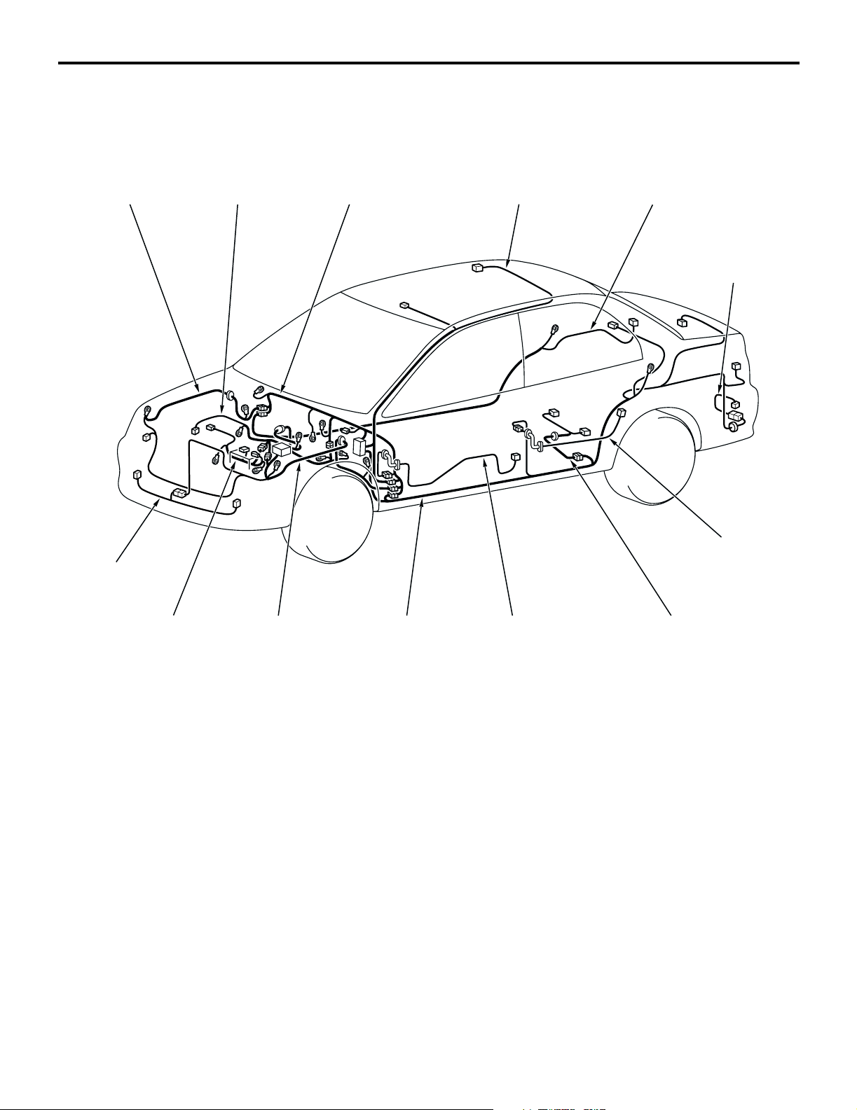
OVERALL WIRING DIAGRAM <SEDAN (LHD) >
Front wiring
harness (RH)
Control wiring
harness
Instrument panel
wiring harness
Roof wiring
harness
M1801000100569
Floor wiring
harness (RH)
Rear bumper
wiring harness
Front bumper
wiring harness
Battery wiring
harness
Front wiring
harness (LH)
Floor wiring
harness (LH)
NOTE: .
1. This illustration shows only major wiring harnesses.
2. *: also equipped at the right side.
Front door
wiring harness
Rear door
wiring harness
Fuel wiring
*
harness
AC301175
*
AB
Page 3
CONFIGURATION DIAGRAMS
OVERALL CONFIGURATION DIAGRAM
80-3
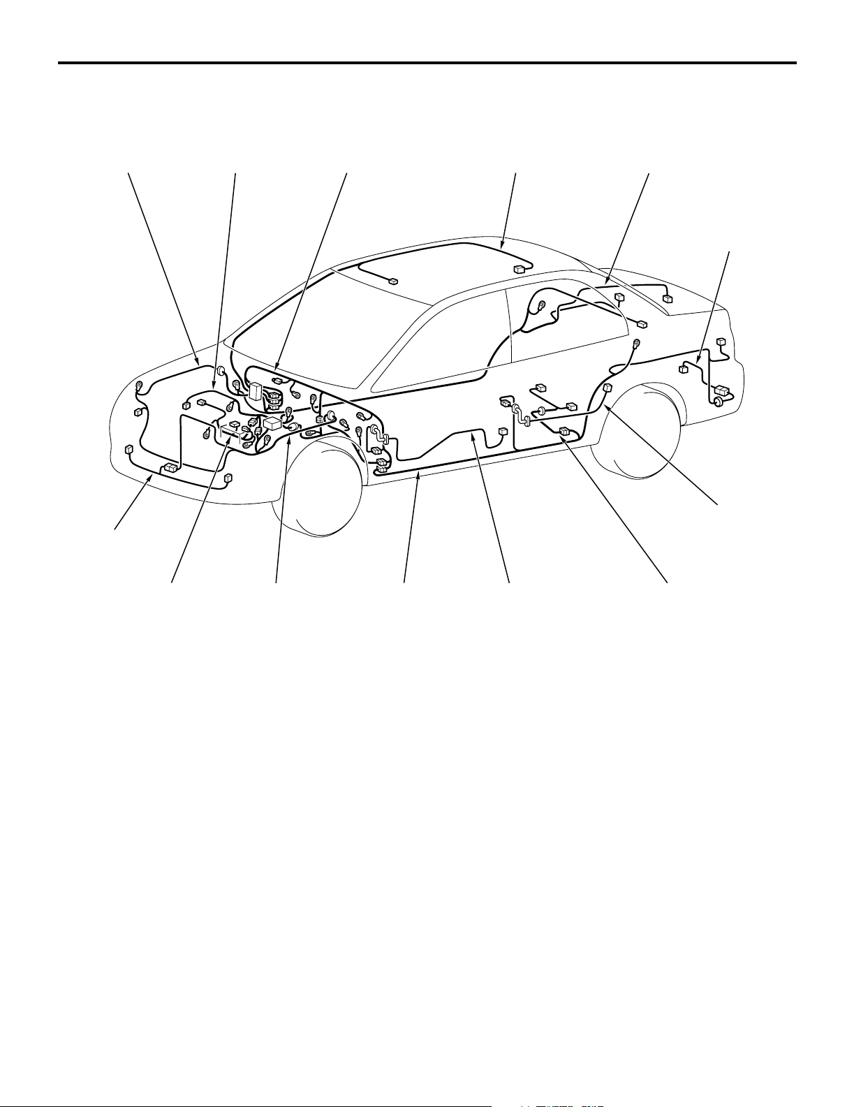
OVERALL WIRING DIAGRAM <SEDAN (RHD) >
Front wiring
harness (RH)
Control wiring
harness
Instrument panel
wiring harness
Roof wiring
harness
M1801000100581
Floor wiring
harness (RH)
Rear bumper
wiring harness
Front bumper
wiring harness
Battery wiring
harness
Front wiring
harness (LH)
Floor wiring
harness (LH)
NOTE: .
1. This illustration shows only major wiring harnesses.
2. *: also equipped at the right side.
Front door
wiring harness
Rear door
wiring harness
Fuel wiring
*
harness
AC301176
*
AB
Page 4
80-4
CONFIGURATION DIAGRAMS
OVERALL CONFIGURATION DIAGRAM
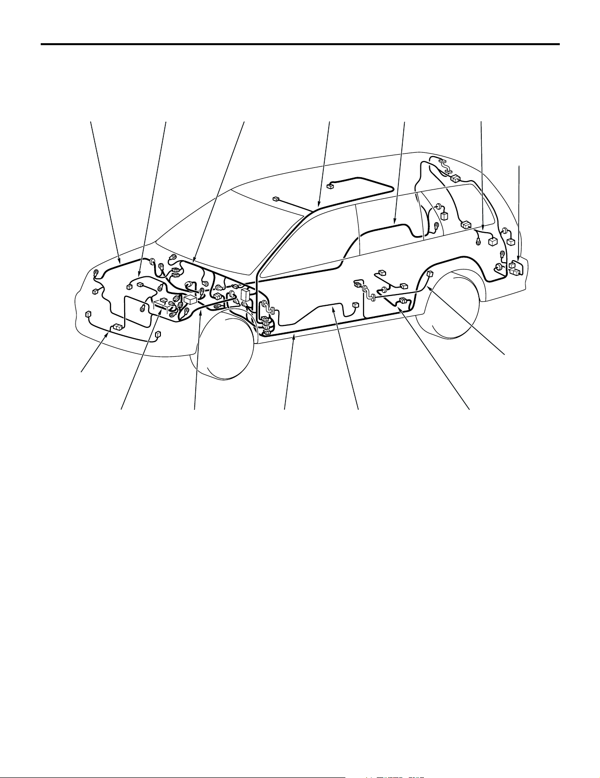
OVERALL WIRING DIAGRAM <WAGON (LHD) >
Front wiring
harness (RH)
Control wiring
harness
Instrument panel
wiring harness
Roof wiring
harness
Floor wiring
harness (RH)
M1801000100592
Tailgate wiring
harness
Rear bumper
wiring harness
Front bumper
wiring harness
Battery wiring
harness
Front wiring
harness (LH)
Floor wiring
harness (LH)
NOTE: .
1. This illustration shows only major wiring harnesses.
2. *: also equipped at the right side.
Front door
wiring harness
Rear door
wiring harness
Fuel wiring
*
harness
AC301177
*
AB
Page 5
CONFIGURATION DIAGRAMS
OVERALL CONFIGURATION DIAGRAM
80-5
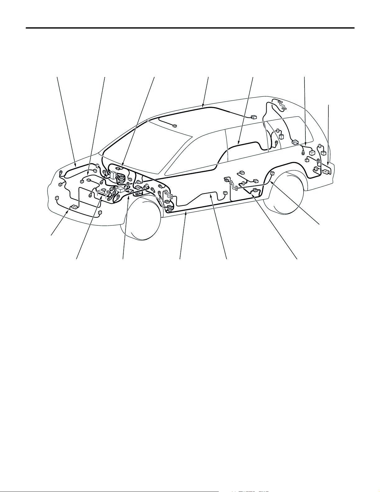
OVERALL WIRING DIAGRAM <WAGON (RHD) >
Front wiring
harness (RH)
Control wiring
harness
Instrument panel
wiring harness
Roof wiring
harness
Floor wiring
harness (RH)
M1801000100600
Tailgate wiring
harness
Rear bumper
wiring harness
Front bumper
wiring harness
Battery wiring
harness
Front wiring
harness (LH)
Floor wiring
harness (LH)
NOTE: .
1. This illustration shows only major wiring harnesses.
2. *: also equipped at the right side.
Front door
wiring harness
Rear door
wiring harness
Fuel wiring
*
harness
AC301178
*
AB
Page 6
80-6
CONFIGURATION DIAGRAMS
ENGINE COMPARTMENT
ENGINE COMPARTMENT
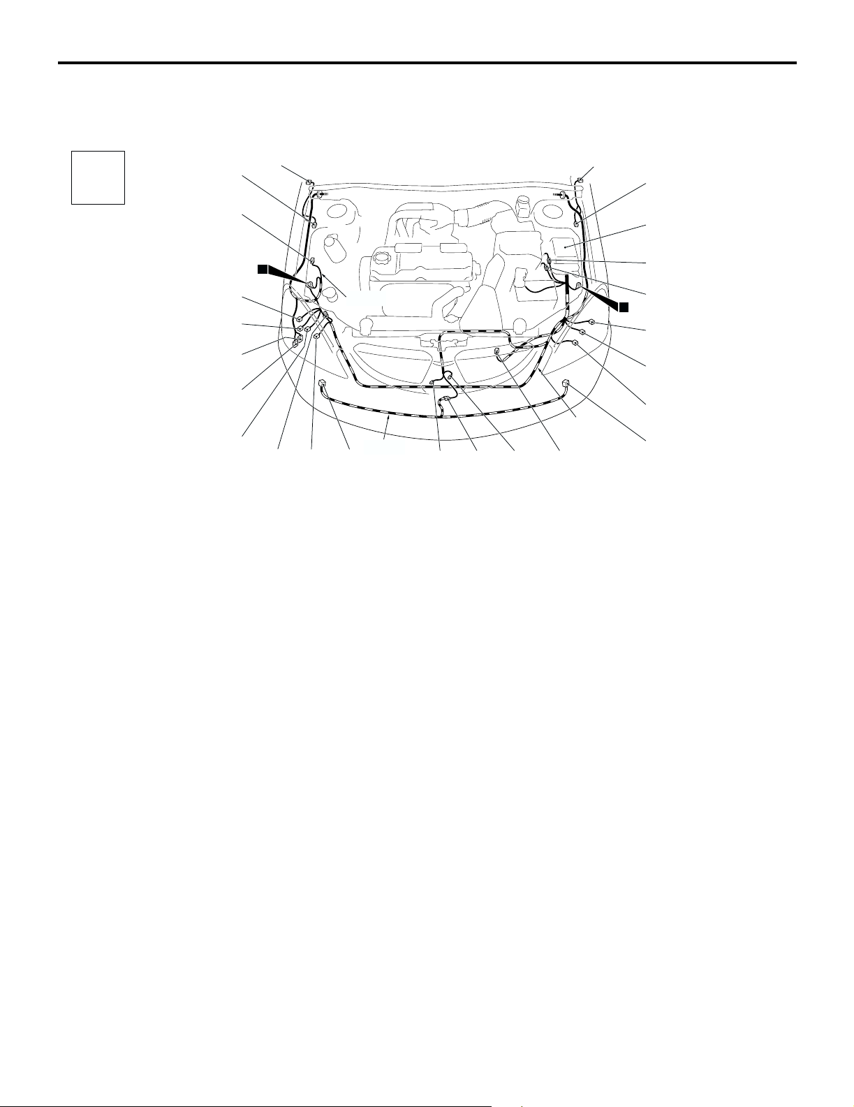
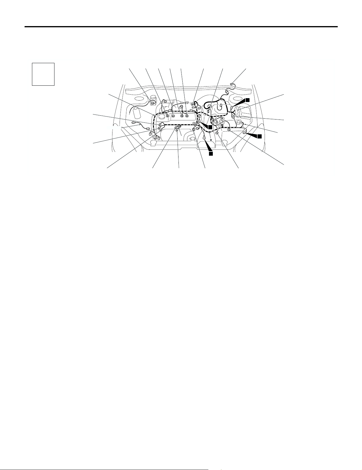
ENGINE COMPARTMENT <LHD>
M1801000301298
Connector
symbol
A-32
A-01
A
A-31
1
A-29
A-28
A-27
Connector colour
code
B : Black
BR : Brown
G : Green
GR : Gray
L : Blue
None : Milk white
O : Orange
R : Red
V : Violet
Y : Yellow
A-26
A-25
A-23A-24 A-22
A-01 (2-GR) Side turn signal lamp (RH)
A-02 (2-GR) Side turn signal lamp (LH)
A-03 (2-B) Wheel speed sensor (Front: LH)
A-04X (4) Front fog lamp relay or spare connector
(for front fog lamp)
A-05X (4) Horn relay
A-09X (4) Fan control relay
A-10X (11) Front-ECU
A-11X (11) Front-ECU
A-12 (2-B) Front wiring harness (LH) and control
wiring harness combination
A-13 (12-B) Front wiring harness (LH) and control
wiring harness combination
A-14 (3-B) Headlamp (LH)
A-15 (6-B) Front combination lamp (LH)
A-16 (2) Front turn signal lamp (LH)
Front wiring
harness (RH)
Front bumper
wiring harness
A-02
A-03
A-04X
A-05X
A-09X
A-10X
A-11X
A-12
A-13
12
A-14
A-15
A-16
Front wiring
harness (LH)
A-21
A-18A-19A-20
A-17
A-17 (2-B) Front fog lamp (LH)
A-18 (3-GR) Cooling fan motor drive control unit
A-19 (1-B) Horn (HI)
A-20 (2-B) Front wiring harness (LH) and front
bumper wiring harness combination
A-21 (1-B) Horn (LO)
A-22 (2-B) Front fog lamp (RH)
A-23 (2) Front turn signal lamp (RH)
A-24 (1) Spare connector (for front fog lamp)
A-25 (6-B) Front combination lamp (RH)
A-26 (2) Windshield washer motor
A-27 (2-G) Rear washer motor
A-28 (2-B) Headlamp washer motor
A-29 (3-B) Headlamp (RH)
A-31 (2-BR) Dual pressure switch
A-32 (2-B) Wheel speed sensor (Front: RH)
AC301122
AB
Page 7
CONFIGURATION DIAGRAMS
ENGINE COMPARTMENT
80-7
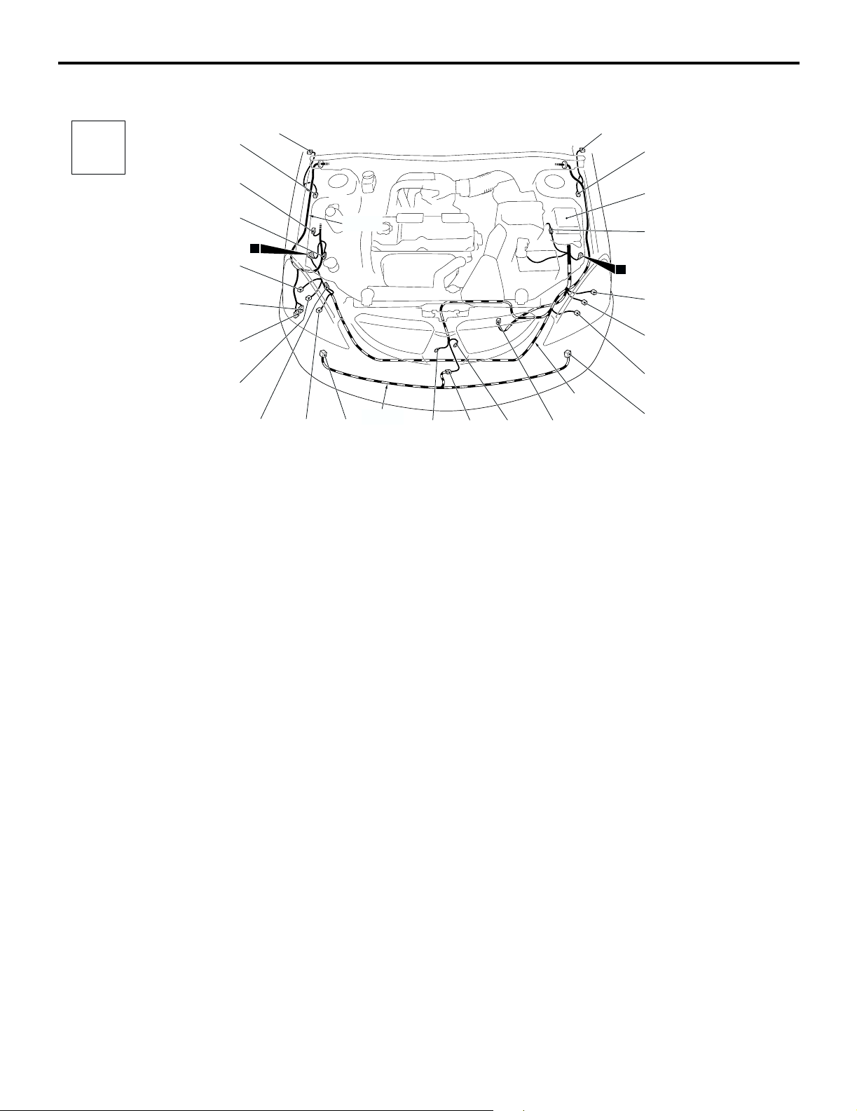
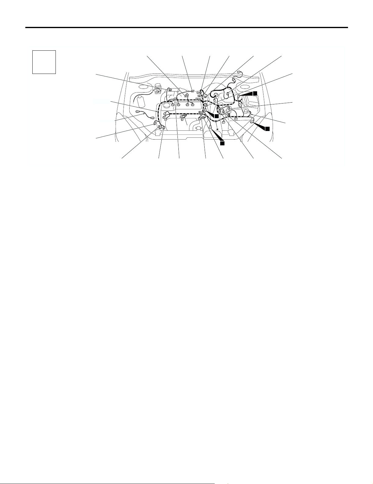
ENGINE COMPARTMENT <RHD>
M1801000301306
Connector
symbol
A-32
A-01
A
A-31
A-30
1
A-29
A-27
Connector colour
code
B : Black
BR : Brown
G : Green
GR : Gray
L : Blue
None : Milk white
O : Orange
R : Red
V : Violet
Y : Yellow
A-26
A-25
A-23A-24 A-22
A-01 (2-GR) Side turn signal lamp (RH)
A-02 (2-GR) Side turn signal lamp (LH)
A-03 (2-B) Wheel speed sensor (Front: LH)
A-04X (4) Front fog lamp relay or spare connector
(for front fog lamp)
A-05X (4) Horn relay
A-09X (4) Fan control relay
A-10X (11) Front-ECU
A-11X (11) Front-ECU
A-12 (2-B) Front wiring harness (LH) and control
wiring harness combination
A-14 (3-B) Headlamp (LH)
A-15 (6-B) Front combination lamp (LH)
A-16 (2) Front turn signal lamp (LH)
A-17 (2-B) Front fog lamp (LH)
Front wiring
harness (RH)
Front bumper
wiring harness
A-02
A-03
A-04X
A-05X
A-09X
A-10X
A-11X
A-12
12
A-14
A-15
A-16
Front wiring
A-21
harness (LH)
A-18A-19A-20
A-17
A-18 (3-GR) Cooling fan motor drive control unit
A-19 (1-B) Horn (HI)
A-20 (2-B) Front wiring harness (LH) and front
bumper wiring harness combination
A-21 (1-B) Horn (LO)
A-22 (2-B) Front fog lamp (RH)
A-23 (2) Front turn signal lamp (RH)
A-24 (1) Spare connector (for front fog lamp)
A-25 (6-B) Front combination lamp (RH)
A-26 (2) Windshield washer motor
A-27 (2-G) Rear washer motor
A-29 (3-B) Headlamp (RH)
A-30 (2-GR) No connection
A-31 (2-BR) Dual pressure switch
A-32 (2-B) Wheel speed sensor (Front: RH)
AC301125
AB
Page 8
80-8
CONFIGURATION DIAGRAMS
ENGINE AND TRANSMISSION
ENGINE AND TRANSMISSION
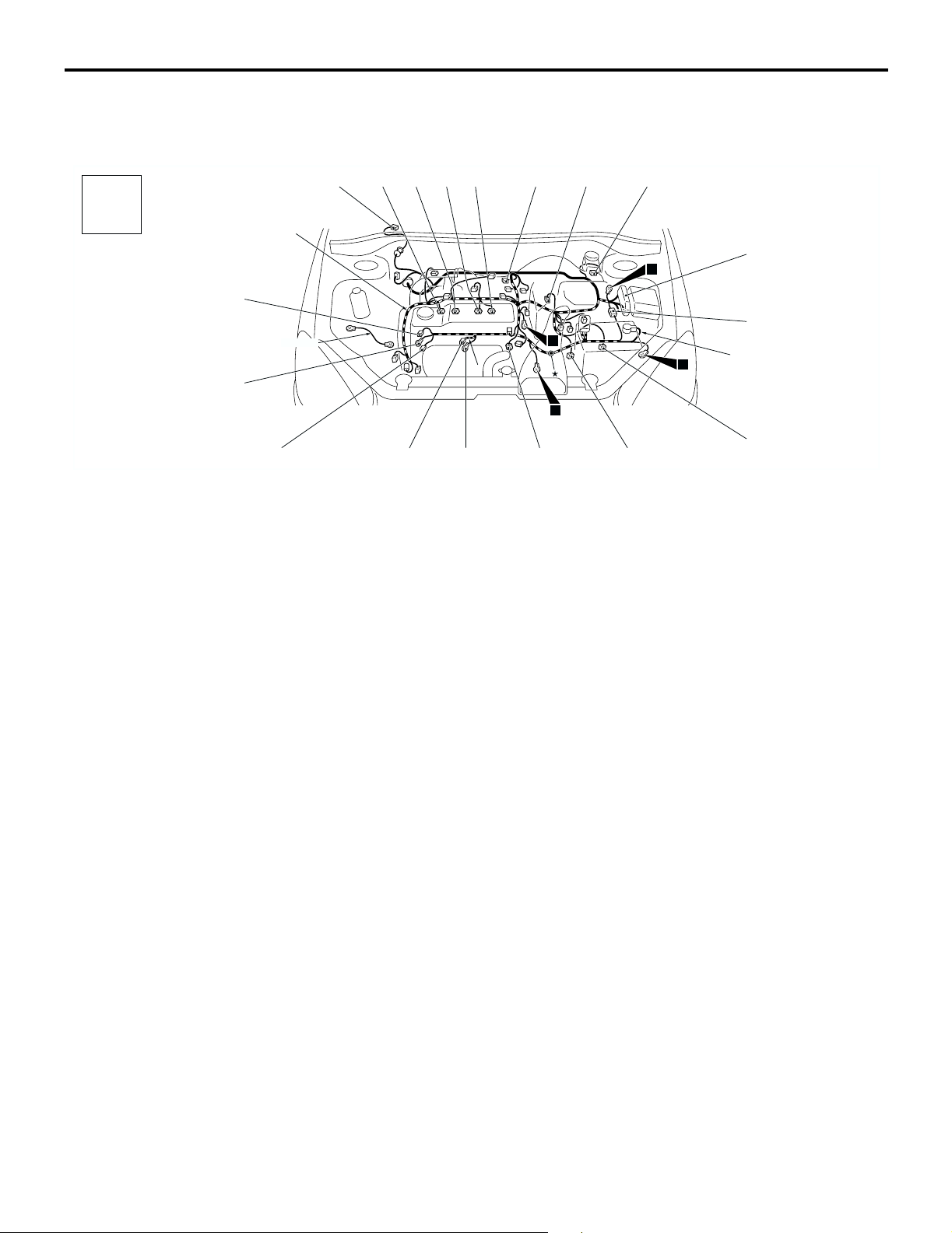
ENGINE AND TRANSMISSION <4G1-MPI (LHD) >
Connector
symbol
-01
thru
B
-26
Connector colour
code
B : Black
BR : Brown
G : Green
GR : Gray
L : Blue
None : Milk white
O : Orange
R : Red
V : Violet
Y : Yellow
B-26
B-25
Control wiring
harness
B-24
Earth cable
B-01 (5-GR) Windshield wiper motor
B-02 (2-GR) Fuel injector 1
B-03 (2-GR) Fuel injector 2
B-04 (2-GR) Fuel injector 3
B-05 (2-GR) Fuel injector 4
B-06 (3-GR) Throttle body throttle sensor
B-07 (3-B) Vehicle speed sensor <M/T>
B-09 (2-GR) Brake fluid level indicator switch
B-10X (1) Engine speed detection connector
B-15X (4) A/T control relay
B-16X (4) Engine control relay
B-17X (4) A/C compressor relay
B-18 (6-B) Control wiring harness and battery wiring
harness combination
B-19 (10-GR) A/T control solenoid valve assembly
B-01
B-02
B-23
B-03
B-04
B-05
*
B-22
B-20 (10-B) Inhibitor switch <A/T>
B-21 (4-B) Engine control oxygen sensor (Front)
B-22 (1) Starter
B-23 (1-B) Starter
B-24 (1-B) Engine oil pressure switch
B-25 (1) Alternator
B-26 (4-GR) Alternator
NOTE: On A/T only, the standard routing positions
for the corrugated tube and wiring harness are
marked by*.
B-06
B-21
M1801000400689
B-07
10
*
9
B-20
B-09
B-10X
B-15X
B-16X
13
11
B-17X
B-18
Battery wiring
harness
B-19
AC301128
AB
Page 9
CONFIGURATION DIAGRAMS
ENGINE AND TRANSMISSION
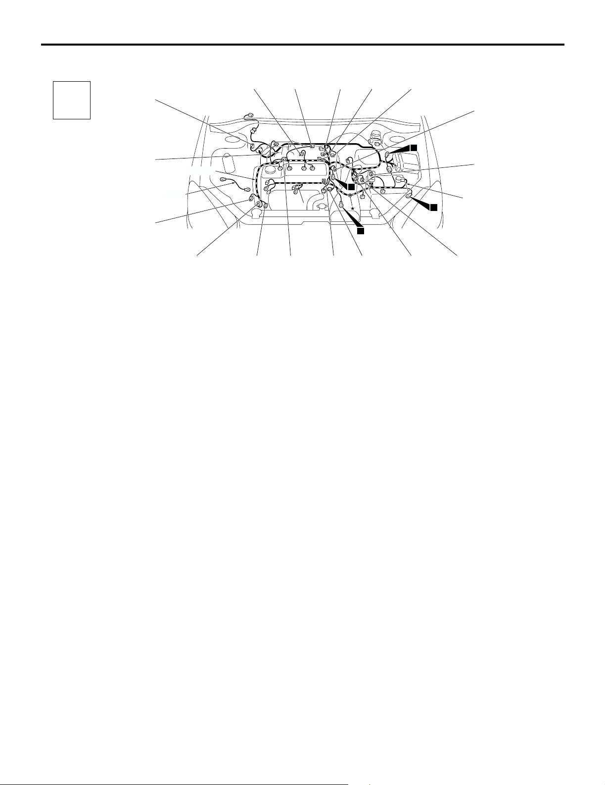
ENGINE AND TRANSMISSION <4G1-MPI (LHD) > (CONTINUED)
80-9
Connector
symbol
-101
thru
B
-118
Connector colour
code
B : Black
BR : Brown
G : Green
GR : Gray
L : Blue
None : Milk white
O : Orange
R : Red
V : Violet
Y : Yellow
B-118
B-117
B-116
Earth cable
Control wiring
harness
B-115
B-101 B-102
B-114
B-101 (2-BR) Emission solenoid valve (EGR system)
B-102 (4-GR) Inlet manifold absolute pressure sensor
B-103 (6-B) Throttle body idle speed control servo
B-104 (3-GR) Ignition coil 1
B-105 (2-B) Emission solenoid valve (Purge control
system)
B-107 (3-B) Camshaft position sensor
B-108 (3-GR) Output shaft speed sensor <A/T>
B-109 (3-B) Input shaft speed sensor <A/T>
B-110 (2-B) Back-up lamp switch <M/T>
B-111 (2-B) Water temperature sensor unit
B-112 (1-B) Water temperature gauge unit
B-105
B-110
B-107
13
B-108
Battery wiring
11
harness
B-109
B-113
B-103
*
B-112
B-104
10
*
9
B-111
B-113 (3-GR) Ignition coil 2
B-114 (1-B) A/C compressor
B-115 (1) Power steering fluid pressure switch
B-116 (3-B) Engine crank angle sensor
B-117 (2-GR) Engine control detonation sensor
B-118 (28-GR) ABS-ECU
NOTE: On A/T only, the standard routing positions
for the corrugated tube and wiring harness are
marked by*.
AC301128
AC
Page 10
80-10
ENGINE AND TRANSMISSION <4G1-MPI (RHD) >
CONFIGURATION DIAGRAMS
ENGINE AND TRANSMISSION
M1801000400690
Connector
symbol
-01
thru
B
-26
Connector colour
code
B : Black
BR : Brown
G : Green
GR : Gray
L : Blue
None : Milk white
O : Orange
R : Red
V : Violet
Y : Yellow
Control wiring
harness
B-26
B-25
Earth cable
B-24
B-09
B-02
B-23
B-03
B-04 B-05
B-01 (5-GR) Windshield wiper motor
B-02 (2-GR) Fuel injector 1
B-03 (2-GR) Fuel injector 2
B-04 (2-GR) Fuel injector 3
B-05 (2-GR) Fuel injector 4
B-06 (3-GR) Throttle body throttle sensor
B-07 (3-B) Vehicle speed sensor <M/T>
B-09 (2-GR) Brake fluid level indicator switch
B-10X (1) Engine speed detection connector
B-14X (4) Ignition coil relay
B-15X (4) A/T control relay
B-16X (4) Engine control relay
B-17X (4) A/C compressor relay
B-18 (6-B) Control wiring harness and battery wiring
harness combination
B-19 (10-GR) A/T control solenoid valve assembly
B-21
B-07
10
*
9
B-20
B-01
B-10X
B-14X
B-15X
B-16X
13
11
B-17X
B-18
Battery wiring
harness
B-19
B-06
*
B-22
B-20 (10-B) Inhibitor switch <A/T>
B-21 (4-B) Engine control oxygen sensor (Front)
B-22 (1) Starter
B-23 (1-B) Starter
B-24 (1-B) Engine oil pressure switch
B-25 (1) Alternator
B-26 (4-GR) Alternator
NOTE: On A/T only, the standard routing positions
for the corrugated tube and wiring harness are
marked by*.
AC301131
AB
Page 11
CONFIGURATION DIAGRAMS
ENGINE AND TRANSMISSION
ENGINE AND TRANSMISSION <4G1-MPI (RHD) > (CONTINUED)
80-11
Connector
symbol
-101
thru
B
-118
Connector colour
code
B : Black
BR : Brown
G : Green
GR : Gray
L : Blue
None : Milk white
O : Orange
R : Red
V : Violet
Y : Yellow
B-117
Control wiring
harness
B-116
Earth cable
B-115
B-101 B-102
B-114
B-101 (2-BR) Emission solenoid valve (EGR system)
B-102 (4-GR) Inlet manifold absolute pressure sensor
B-103 (6-B) Throttle body idle speed control servo
B-104 (3-GR) Ignition coil 1
B-105 (2-B) Emission solenoid valve (Purge control
system)
B-107 (3-B) Camshaft position sensor
B-108 (3-GR) Output shaft speed sensor <A/T>
B-109 (3-B) Input shaft speed sensor <A/T>
B-110 (2-B) Back-up lamp switch <M/T>
B-111 (2-B) Water temperature sensor unit
B-112 (1-B) Water temperature gauge unit
B-113
B-103
*
B-112
B-104
10
*
9
B-111
B-105
B-110
B-118
B-107
13
B-108
Battery wiring
11
harness
B-109
B-113 (3-GR) Ignition coil 2
B-114 (1-B) A/C compressor
B-115 (1) Power steering fluid pressure switch
B-116 (3-B) Engine crank angle sensor
B-117 (2-GR) Engine control detonation sensor
B-118 (28-GR) ABS-ECU
NOTE: On A/T only, the standard routing positions
for the corrugated tube and wiring harness are
marked by*.
AC301131
AC
Page 12

80-12
ENGINE AND TRANSMISSION <4G6-MPI (LHD) >
CONFIGURATION DIAGRAMS
ENGINE AND TRANSMISSION
M1801000400708
Connector
symbol
-01
thru
B
-26
Connector colour
code
B : Black
BR : Brown
G : Green
GR : Gray
L : Blue
None : Milk white
O : Orange
R : Red
V : Violet
Y : Yellow
B-26
B-25
Control wiring
harness
B-01
B-02
B-01 (5-GR) Windshield wiper motor
B-02 (2-GR) Fuel injector 1
B-03 (2-GR) Fuel injector 2
B-04 (2-GR) Fuel injector 3
B-05 (2-GR) Fuel injector 4
B-06 (4-B) Throttle body throttle sensor
B-07 (3-B) Vehicle speed sensor
B-08 (7-B) Air cleaner air flow sensor
B-09 (2-GR) Brake fluid level indicator switch
B-10X (1) Engine speed detection connector
B-03
B-04
Earth
cable
10
B-05
B-24
B-07
B-06
9
B-23
B-22
B-08
B-09
B-10X
B-16X
13
11
B-21
B-17X
B-18
Battery wiring
harness
AC301134
AB
B-16X (4) Engine control relay
B-17X (4) A/C compressor relay
B-18 (6-B) Control wiring harness and battery wiring
harness combination
B-21 (4-B) Engine control oxygen sensor (Front)
B-22 (1) Starter
B-23 (1-B) Starter
B-24 (1-B) Engine oil pressure switch
B-25 (1) Alternator
B-26 (4-GR) Alternator
Page 13

CONFIGURATION DIAGRAMS
ENGINE AND TRANSMISSION
ENGINE AND TRANSMISSION <4G6-MPI (LHD) > (CONTINUED)
80-13
Connector
symbol
-101
thru
B
-118
Connector colour
code
B : Black
BR : Brown
G : Green
GR : Gray
L : Blue
None : Milk white
O : Orange
R : Red
V : Violet
Y : Yellow
B-118
B-117
B-116
Control wiring
harness
B-115
B-105
B-114
B-101
B-113
B-101 (2-BR) Emission solenoid valve (EGR system)
B-103 (6-B) Throttle body idle speed control servo
B-104 (3-GR) Ignition coil 1
B-105 (2-B) Emission solenoid valve (Purge control
system)
B-106 (1-B) Capacitor
B-107 (3-B) Camshaft position sensor
B-110 (2-B) Back-up lamp switch
B-106
13
11
B-111
B-112
Battery wiring
harness
B-110
Earth cable
10
B-103
9
B-104
B-107
B-111 (2-B) Water temperature sensor unit
B-112 (1-B) Water temperature gauge unit
B-113 (3-GR) Ignition coil 2
B-114 (1-B) A/C compressor
B-115 (1-B) Power steering fluid pressure switch
B-116 (3-B) Engine crank angle sensor
B-117 (2-GR) Engine control detonation sensor
B-118 (28-GR) ABS-ECU
AC301134
AC
Page 14

80-14
ENGINE AND TRANSMISSION <4G6-MPI (RHD) >
Connector
symbol
B
-01
thru
-26
B-09
Control wiring
harness
CONFIGURATION DIAGRAMS
ENGINE AND TRANSMISSION
M1801000400719
B-04
B-02
B-03
Earth
cable
B-05
B-06
B-07
B-01
B-08
B-10X
13
B-14X
B-16X
B-17X
Connector colour
code
B : Black
BR : Brown
G : Green
GR : Gray
L : Blue
None : Milk white
O : Orange
R : Red
V : Violet
Y : Yellow
B-26
B-25
B-01 (5-GR) Windshield wiper motor
B-02 (2-GR) Fuel injector 1
B-03 (2-GR) Fuel injector 2
B-04 (2-GR) Fuel injector 3
B-05 (2-GR) Fuel injector 4
B-06 (4-B) Throttle body throttle sensor
B-07 (3-B) Vehicle speed sensor
B-08 (7-B) Air cleaner air flow sensor
B-09 (2-GR) Brake fluid level indicator switch
B-10X (1) Engine speed detection connector
B-14X (4) Ignition coil relay
B-21
B-18
Battery wiring
harness
AC301137
AB
10
B-24
9
11
B-23
B-22
B-16X (4) Engine control relay
B-17X (4) A/C compressor relay
B-18 (6-B) Control wiring harness and battery wiring
harness combination
B-21 (4-B) Engine control oxygen sensor (Front)
B-22 (1) Starter
B-23 (1-B) Starter
B-24 (1-B) Engine oil pressure switch
B-25 (1) Alternator
B-26 (4-GR) Alternator
Page 15

CONFIGURATION DIAGRAMS
ENGINE AND TRANSMISSION
ENGINE AND TRANSMISSION <4G6-MPI (RHD) > (CONTINUED)
80-15
Connector
symbol
-101
thru
B
-118
Connector colour
code
B : Black
BR : Brown
G : Green
GR : Gray
L : Blue
None : Milk white
O : Orange
R : Red
V : Violet
Y : Yellow
B-117
B-116
Control wiring
harness
B-115
B-105 B-101
B-114
B-113
B-101 (2-BR) Emission solenoid valve (EGR system)
B-103 (6-B) Throttle body idle speed control servo
B-104 (3-GR) Ignition coil 1
B-105 (2-B) Emission solenoid valve (Purge control
system)
B-106 (1-B) Capacitor
B-107 (3-B) Camshaft position sensor
B-110 (2-B) Back-up lamp switch
B-107
B-104
B-106
B-118
13
11
B-111
B-112
Battery wiring
harness
B-110
B-103
Earth cable
10
9
B-111 (2-B) Water temperature sensor unit
B-112 (1-B) Water temperature gauge unit
B-113 (3-GR) Ignition coil 2
B-114 (1-B) A/C compressor
B-115 (1-B) Power steering fluid pressure switch
B-116 (3-B) Engine crank angle sensor
B-117 (2-GR) Engine control detonation sensor
B-118 (28-GR) ABS-ECU
AC301137
AC
Page 16

80-16
CONFIGURATION DIAGRAMS
DASH PANEL
DASH PANEL
DASH PANEL <LHD>
M1801000601040
Connector
symbol
-01
thru
C
-36
Connector colour
code
B : Black
BR : Brown
G : Green
GR : Gray
L : Blue
None : Milk white
O : Orange
R : Red
V : Violet
Y : Yellow
C-01
C-36
C-35
C-34
C-33
C-32
C-31
C-29
C-27
C-25
C-02
16
C-24
C-01 (6) Fog lamp switch
C-02 (1) Spare connector (for front fog lamp
switch)
C-03 (22-B) J/C (5)
C-04 (21) Combination meter
C-05 (4) Stop lamp switch
C-06 (21-L) Combination meter
C-08 (1-B) Spare connector (for audio)
C-09 (14) Spare connector (for audio)
C-10 (1) Instrument panel wiring harness and
antenna feeder cable combination
C-11 (16-B) Diagnosis connector
C-12 (33) J/C (6)
C-13 (25) Instrument panel wiring harness and
control wiring harness combination
C-14 (10-GR) Instrument panel wiring harness and
control wiring harness combination
C-15 (22-L) Instrument panel wiring harness and
control wiring harness combination
C-19 (12) Diagnosis connector
C-21 (3) Front wiring harness (LH) and instrument
panel wiring harness combination
C-22
C-04C-03
C-05
J/B
C-21
C-06
6
Instrument panel
wiring harness
C-19
C-08
5
14
15
C-15
C-09
Control wiring
harness
C-14
C-10
C-11
C-12
C-13
C-22 (13) Instrument panel wiring harness and floor
wiring harness (LH) combination
C-24 (6-L) Instrument panel wiring harness and roof
wiring harness combination
C-25
(11-B
*
Instrument panel wiring harness and floor
)
wiring harness (LH) combination
C-27 (25) Front wiring harness (LH) and instrument
panel wiring harness combination
C-29 (20) Instrument panel wiring harness and front
door wiring harness (LH) combination
C-31 (6) Instrument panel wiring harness and roof
wiring harness combination <Wagon>
C-32 (22-B) J/C (4)
C-33 (6-L) Rheostat
C-34 (6-GR) Headlamp levelling switch
C-35 (22-L) J/C (2)
C-36 (11-B) Remote controlled mirror switch
NOTE: The connector colour marked by * is for the
female side. For the male side, the colour is grey for
Sedan, and milk white for Wagon.
AC301140
AB
Page 17

DASH PANEL <LHD> (CONTINUED)
CONFIGURATION DIAGRAMS
DASH PANEL
80-17
Connector
symbol
-101
thru
C
-140
Connector colour
code
B : Black
BR : Brown
G : Green
GR : Gray
L : Blue
None : Milk white
O : Orange
R : Red
V : Violet
Y : Yellow
C-140
C-139
C-133
Instrument panel
wiring harness
C-132
C-101
C-102
Y
C-131
C-103
4
C-130
C-101 (4) Hazard warning lamp switch
C-102 (4) Clock
C-103 (22-GR) J/C (1)
C-104 (22-GR) J/C (3)
C-106 (7) Instrument panel wiring harness and A/C
wiring harness combination
C-107 (7) Outside /Inside air selection damper
control motor
C-108 (2-R) Air bag module (squib) <Passenger’s
side>
C-109 (4) Resistor
C-110 (2) Blower motor
C-112 (16) Instrument panel wiring harness and front
door wiring harness (RH) combination
C-114 (25) Front wiring harness (RH) and instrument
panel wiring harness combination
C-116
(9-GR
*
Instrument panel wiring harness and floor
)
wiring harness (RH) combination
C-119 (13) Instrument panel wiring harness and floor
wiring harness (RH) combination
C-122 (35-GR) Engine-A/T-ECU <A/T>
C-104 C-106 C-107
Antenna
feeder
cable
C-108
A/C wiring
harness
C-109
3
C-128
C-129
C-126
C-127
Control wiring
harness
C-124
C-125
C-122
C-123
C-119
2
C-116
C-110
C-112
C-114
C-123 (26-Y) Engine-ECU <M/T>
C-124 (26-GR) Engine-A/T-ECU <A/T>
C-125 (16-Y) Engine-ECU <M/T>
C-126 (28-GR) Engine-A/T-ECU <A/T>
C-127 (12-Y) Engine-ECU <M/T>
C-128 (30-GR) Engine-A/T-ECU <A/T>
C-129 (22-Y) Engine-ECU <M/T>
C-130 (4) Engine control oxygen sensor (Rear)
C-131 (20-Y) SRS-ECU
C-132 (28-Y) SRS-ECU
C-133 (20-Y) SRS-ECU
C-139 (16-B) A/C-ECU or heater control unit
C-140 (6) Blower switch
NOTE: The connector colour marked by
*
is for the
female side.For the male side, the colour is grey for
Sedan, and milk white for Wagon.
AC301143
AB
Page 18

80-18
DASH PANEL <LHD> (CONTINUED)
CONFIGURATION DIAGRAMS
DASH PANEL
Connector
symbol
-201
thru
C
-227
STEERING COLUMN
Clock spring
Y
C-207
Instrument panel
wiring harness
C-206
C-201C-202C-203C-203C-204C-205
C-201 (6) Ignition switch
C-202 (7) Key reminder switch
C-203 (10) Column switch
C-204 (6) Clock spring
C-205 (4-Y) Clock spring
C-206 (1) Horn switch
C-207 (2) Air bag module (squib) <Driver’s side>
C-208 (13) Instrument panel wiring harness and J/B
combination
C-209 (14) Instrument panel wiring harness and J/B
combination
C-210 (6) Instrument panel wiring harness and J/B
combination
C-211 (1-B) Instrument panel wiring harness and J/B
combination
C-212 (28) Instrument panel wiring harness and J/B
combination
(Front view)
C-208 C-209 C-210 C-211
C-224
C-223
C-222
C-221
C-220
JUNCTION BLOCK
C-212
C-213
C-214
C-215
C-217C-218C-219
(Rear view)
C-225
C-226C-227
AC304413
C-213 (5) Rear window defogger relay
C-214 (5) Blower relay
C-215 (15) Floor wiring harness (LH) and J/B
combination
C-217 (3) Roof wiring harness and J/B combination
C-218 (4) Rear fog lamp relay
C-219 (4) Accessory socket relay
C-220 (4) Fuel pump relay (2)
C-221 (4) Heated seat relay
C-222 (4) Fuel pump relay (1)
C-223 (5) Power window relay
C-224 (2) No connection
C-225 (20) ETACS-ECU
C-226 (24) ETACS-ECU
C-227 (24-GR) ETACS-ECU
AB
Page 19

CONFIGURATION DIAGRAMS
DASH PANEL
80-19
DASH PANEL <RHD>
M1801000601051
Connector
symbol
-01
thru
C
-37
C-10
C-11
C-37
Connector colour
code
B : Black
BR : Brown
G : Green
GR : Gray
L : Blue
None : Milk white
O : Orange
R : Red
V : Violet
Y : Yellow
C-16
C-01 (6) Fog lamp switch
C-02 (1) Spare connector (for front fog lamp
switch)
C-04 (21) Combination meter
C-05 (4) Stop lamp switch
C-06 (21-L) Combination meter
C-07 (22-GR) J/C (3)
C-08 (1-B) Spare connector (for audio)
C-09 (14) Spare connector (for audio)
C-10 (1) Instrument panel wiring harness and
antenna feeder cable combination
C-11 (16-B) Diagnosis connector
C-16 (20-Y) SRS-ECU
C-17 (28-Y) SRS-ECU
C-18 (20-Y) SRS-ECU
C-19 (12) Diagnosis connector
C-20 (2) No connection
C-23 (13) Instrument panel wiring harness and floor
wiring harness (RH) combination
C-09 C-08
Control wiring
harness
C-17 C-18
Instrument panel
wiring harness
4
Y
C-19
C-04 C-07 C-06 C-05 C-02 C-01
C-36
6
2
J/B
C-35
C-23
C-32
C-34
C-33
C-31
C-30
C-28
C-26
C-24C-20
AC301149
AB
C-24 (6-L) Instrument panel wiring harness and roof
wiring harness combination
C-26 (9-GR) Instrument panel wiring harness and floor
wiring harness (RH) combination
C-28 (25) Front wiring harness (RH) and instrument
panel wiring harness combination
C-30 (20) Instrument panel wiring harness and front
door wiring harness (RH) combination
C-31 (6) Instrument panel wiring harness and roof
wiring harness combination <Wagon>
C-32 (22-B) J/C (4)
C-33 (6-L) Rheostat
C-34 (6-GR) Headlamp levelling switch
C-35 (22-L) J/C (2)
C-36 (11-B) Remote controlled mirror switch
C-37 (4) Engine control oxygen sensor (Rear)
Page 20

80-20
DASH PANEL <RHD> (CONTINUED)
CONFIGURATION DIAGRAMS
DASH PANEL
Connector
symbol
-101
thru
C
-140
Connector colour
code
B : Black
BR : Brown
G : Green
GR : Gray
L : Blue
None : Milk white
O : Orange
R : Red
V : Violet
Y : Yellow
C-109
Instrument panel
wiring harness
C-110
C-111
C-113
C-115
C-117
C-118
3
16
C-120
C-121
C-128
C-129
C-106C-107C-108
A/C wiring
harness
Control wiring
harness
C-126
C-127
C-124
C-125
C-101 (4) Hazard warning lamp switch
C-102 (4) Clock
C-103 (22-GR) J/C (1)
C-105 (13) J/C (5)
C-106 (7) Instrument panel wiring harness and A/C
wiring harness combination
C-107 (7) Outside /Inside air selection damper
control motor
C-108 (2-R) Air bag module (squib) <Passenger’s
side>
C-109 (4) Resistor
C-110 (2) Blower motor
C-111 (12) Front wiring harness (LH) and control
wiring harness combination
C-113 (16) Instrument panel wiring harness and front
door wiring harness (LH) combination
C-115 (25) Front wiring harness (LH) and instrument
panel wiring harness combination
C-117
(11-B
*
Instrument panel wiring harness and floor
)
wiring harness (LH) combination
C-118 (6-L) Instrument panel wiring harness and floor
wiring harness (LH) combination
C-120 (13) Instrument panel wiring harness and floor
wiring harness (LH) combination
C-134
C-103
14
C-102
15
C-135
C-101
C-139
C-140
C-138
C-137
C-136
Antenna
feeder
cable
Y
C-105
C-122
C-123
5
C-121 (3) Front wiring harness (LH) and instrument
panel wiring harness combination
C-122 (35-GR) Engine-A/T-ECU <A/T>
C-123 (26-Y) Engine-ECU <M/T>
C-124 (26-GR) Engine-A/T-ECU <A/T>
C-125 (16-Y) Engine-ECU <M/T>
C-126 (28-GR) Engine-A/T-ECU <A/T>
C-127 (12-Y) Engine-ECU <M/T>
C-128 (30-GR) Engine-A/T-ECU <A/T>
C-129 (22-Y) Engine-ECU <M/T>
C-134 (33) J/C (6)
C-135 (22-L) Instrument panel wiring harness and
control wiring harness combination
C-136 (10-GR) Instrument panel wiring harness and
control wiring harness combination
C-137 (25) Instrument panel wiring harness and
control wiring harness combination
C-138 (3) Instrument panel wiring harness and
Instrument panel wiring harness
combination
C-139 (12-B) A/C-ECU or heater control unit
C-140 (6) Blower switch
NOTE: The connector colour marked by
*
is for the
female side.For the male side, the colour is grey.
AC301146
AB
Page 21

DASH PANEL <RHD> (CONTINUED)
CONFIGURATION DIAGRAMS
DASH PANEL
80-21
Connector
symbol
-201
thru
C
-227
STEERING COLUMN
Clock spring
Instrument panel
wiring harness
Y
C-205C-204C-203C-203C-202C-201
C-207
C-206
C-201 (6) Ignition switch
C-202 (7) Key reminder switch
C-203 (10) Column switch
C-204 (6) Clock spring
C-205 (4-Y) Clock spring
C-206 (1) Horn switch
C-207 (2) Air bag module (squib) <Driver’s side>
C-208 (13) Instrument panel wiring harness and J/B
combination
C-209 (14) Instrument panel wiring harness and J/B
combination
C-210 (6) Instrument panel wiring harness and J/B
combination
C-211 (1-B) Instrument panel wiring harness and J/B
combination
C-212 (28) Instrument panel wiring harness and J/B
combination
(Front view)
C-208 C-209 C-210 C-211
C-224
C-223
C-222
C-221
C-220
JUNCTION BLOCK
C-212
C-213
C-214
C-216
C-217C-218C-219
(Rear view)
C-225
C-226C-227
AC304414
C-213 (5) Rear window defogger relay
C-214 (5) Blower relay
C-216 (15) Floor wiring harness (RH) and J/B
combination
C-217 (3) Roof wiring harness and J/B combination
C-218 (4) Rear fog lamp relay
C-219 (4) Accessory socket relay
C-220 (4) Fuel pump relay (2)
C-221 (4) No connection
C-222 (4) Fuel pump relay (1)
C-223 (5) Power window relay
C-224 (2) No connection
C-225 (20) ETACS-ECU
C-226 (24) ETACS-ECU
C-227 (24-GR) ETACS-ECU
AB
Page 22

80-22
CONFIGURATION DIAGRAMS
FLOOR AND ROOF
FLOOR AND ROOF
FLOOR AND ROOF <SEDAN (LHD) >
M1801000900844
Connector
symbol
D
Connector colour
code
B : Black
BR : Brown
G : Green
GR : Gray
L : Blue
None : Milk white
O : Orange
R : Red
V : Violet
Y : Yellow
D-35
D-34
D-33
D-32
D-31
D-30
D-29
D-28
Antenna
feeder cable
D-01 (2) Side impact sensor (Front: RH)
D-02 (3) Door switch (Front: RH)
D-03 (8) Floor wiring harness (RH) and rear door
wiring harness (RH) combination
D-04 (2) Front room lamp
D-05 (2-B) Wheel speed sensor (Rear: RH)
D-06 (2-GR) Rear room lamp
D-07 (3) Door switch (Rear: RH)
D-08 (2-Y) Side impact sensor (Rear: RH)
D-13 (3-B) Fuel tank gauge unit
D-14 (2-Y) Side impact sensor (Rear: LH)
D-15 (3) Door switch (Rear: LH)
D-16 (5-GR) Fuel tank pump
D-17 (2-B) Wheel speed sensor (Rear: LH)
D-18 (8) Floor wiring harness (LH) and fuel wiring
harness combination
D-19 (8) Floor wiring harness (LH) and rear door
wiring harness (LH) combination
D-20 (3) Door switch (Front: LH)
D-03D-02D-01
D-04
D-05
Floor wiring
harness (RH)
D-26
Y
D-25
Instrument panel
wiring harness
D-27 D-24
D-06
Y
Floor wiring
harness (LH)
Y
D-07
Roof wiring
harness
D-23
D-08
7
Y
Fuel wiring
harness
Y
Y
D-22
D-21
D-13
<Vehicles with curtain air bag>
D-04 D-36 D-06 D-37
17
D-14
Antenna
Y
D-19D-20
feeder cable
D-15
D-16
D-17
D-18
Y
Roof wiring
harness
Y
D-21 (2) Side impact sensor (Front: LH)
D-22 (2-B) Seat belt pre-tensioner (LH)
D-23 (2-R) Side air bag module (squib) (LH)
D-24 (3) Heated seat assembly (LH)
D-25 (9) Heated seat switch
D-26 (4) Instrument panel wiring harness and
console wiring harness combination
D-27 (6) Shift switch assembly
D-28 (1) Cigarette lighter
D-29 (1-B) Cigarette lighter
D-30 (2-B) Cigarette lighter illumination lamp
D-31 (2-B) Ashtray illumination lamp
D-32 (3) Heated seat assembly (RH)
D-33 (2-R) Side air bag module (squib) (RH)
D-34 (1-B) Parking brake switch
D-35 (2-B) Seat belt pre-tensioner (RH)
D-36 (2-B) Curtain air bag module (squib) (RH)
D-37 (2-B) Curtain air bag module (squib) (LH)
AC301155
AC
Page 23

CONFIGURATION DIAGRAMS
FLOOR AND ROOF
80-23
FLOOR AND ROOF <SEDAN (RHD) >
M1801000900855
Connector
symbol
D
Connector colour
code
B : Black
BR : Brown
G : Green
GR : Gray
L : Blue
None : Milk white
O : Orange
R : Red
V : Violet
Y : Yellow
D-35
D-34
D-33
D-31
D-30
D-29
Roof wiring
harness
Instrument panel
wiring harness
D-01 (2) Side impact sensor (Front: RH)
D-02 (3) Door switch (Front: RH)
D-03 (8) Floor wiring harness (RH) and rear door
wiring harness (RH) combination
D-04 (2) Front room lamp
D-05 (2-B) Wheel speed sensor (Rear: RH)
D-06 (2-GR) Rear room lamp
D-07 (3) Door switch (Rear: RH)
D-08 (2-Y) Side impact sensor (Rear: RH)
D-13 (3-B) Fuel tank gauge unit
D-14 (2-Y) Side impact sensor (Rear: LH)
D-15 (3) Door switch (Rear: LH)
D-16 (5-GR) Fuel tank pump
D-17 (2-B) Wheel speed sensor (Rear: LH)
D-18 (8) Floor wiring harness (LH) and fuel wiring
harness combination
D-19 (8) Floor wiring harness (LH) and rear door
wiring harness (LH) combination
D-28
D-03D-02D-01
Floor wiring
harness (RH)
Y
D-27
D-04
D-05
D-26
D-06
Y
Floor wiring
harness (LH)
Y
D-23
D-07
D-08
Antenna
feeder cable
7
Y
Fuel wiring
harness
Y
Y
D-22
D-21
D-13
<Vehicles with curtain air bag>
D-04 D-36 D-06 D-37
17
D-14
Y
D-15
D-16
D-17
D-18
D-19D-20
Y
Antenna
feeder cable
Roof wiring
harness
D-20 (3) Door switch (Front: LH)
D-21 (2) Side impact sensor (Front: LH)
D-22 (2-B) Seat belt pre-tensioner (LH)
D-23 (2-R) Side air bag module (squib) (LH)
D-26 (4) Instrument panel wiring harness and
console wiring harness combination
D-27 (6) Shift switch assembly
D-28 (1) Cigarette lighter
D-29 (1-B) Cigarette lighter
D-30 (2-B) Cigarette lighter illumination lamp
D-31 (2-B) Ashtray illumination lamp
D-33 (2-R) Side air bag module (squib) (RH)
D-34 (1-B) Parking brake switch
D-35 (2-B) Seat belt pre-tensioner (RH)
D-36 (2-B) Curtain air bag module (squib) (RH)
D-37 (2-B) Curtain air bag module (squib) (LH)
Y
AC301158
AB
Page 24

80-24
CONFIGURATION DIAGRAMS
FLOOR AND ROOF
FLOOR AND ROOF <WAGON (LHD) >
M1801000900866
Connector
symbol
D
Connector colour
code
B : Black
BR : Brown
G : Green
GR : Gray
L : Blue
None : Milk white
O : Orange
R : Red
V : Violet
Y : Yellow
D-01
D-35
D-34
D-33
D-32
D-27
D-31
D-30
D-29
D-28
D-01 (2) Side impact sensor (Front: RH)
D-02 (3) Door switch (Front: RH)
D-03 (8) Floor wiring harness (RH) and rear door
wiring harness (RH) combination
D-04 (2) Front room lamp
D-05 (2-B) Wheel speed sensor (Rear: RH)
D-06 (2-GR) Rear room lamp
D-07 (3) Door switch (Rear: RH)
D-08 (2-Y) Side impact sensor (Rear: RH)
D-09 (3) Rear personal lamp (RH)
D-10 (3) Luggage room lamp
D-11 (2-B) Diode (for luggage room lamp circuit)
D-12 (3) Rear personal lamp (LH)
D-13 (3-B) Fuel tank gauge unit
D-14 (2-Y) Side impact sensor (Rear: LH)
D-15 (3) Door switch (Rear: LH)
D-16 (5-GR) Fuel tank pump
D-17 (2-B) Wheel speed sensor (Rear: LH)
D-18 (8) Floor wiring harness (LH) and fuel wiring
harness combination
D-19 (8) Floor wiring harness (LH) and rear door
wiring harness (LH) combination
D-26
D-03D-02
D-25
D-04
Antenna
feeder
cable
Y
D-24
D-23
D-05
Roof wiring
harness
Y
D-20
D-07
Y
Instrument panel
wiring harness
D-21
D-08
Floor wiring
harness (RH)
Y
D-22
D-09
D-10
Y
Y
Floor wiring
harness (LH)
D-19
Fuel wiring
harness
D-11
D-12
<Vehicles with curtain air bag>
D-13
D-04 D-36 D-06 D-37
7
D-14
Y
D-17D-18
Antenna
feeder cable
17
D-15
D-16
Y
D-20 (3) Door switch (Front: LH)
D-21 (2) Side impact sensor (Front: LH)
D-22 (2-B) Seat belt pre-tensioner (LH)
D-23 (2-R) Side air bag module (squib) (LH)
D-24 (3) Heated seat assembly (LH)
D-25 (9) Heated seat switch
D-26 (4) Instrument panel wiring harness and
console wiring harness combination
D-27 (6) Shift switch assembly
D-28 (1) Cigarette lighter
D-29 (1-B) Cigarette lighter
D-30 (2-B) Cigarette lighter illumination lamp
D-31 (2-B) Ashtray illumination lamp
D-32 (3) Heated seat assembly (RH)
D-33 (2-R) Side air bag module (squib) (RH)
D-34 (1-B) Parking brake switch
D-35 (2-B) Seat belt pre-tensioner (RH)
D-36 (2-B) Curtain air bag module (squib) (RH)
D-37 (2-B) Curtain air bag module (squib) (LH)
Y
Roof wiring
harness
AC301161
AB
Page 25

CONFIGURATION DIAGRAMS
FLOOR AND ROOF
80-25
FLOOR AND ROOF <WAGON (RHD) >
M1801000900877
Connector
symbol
D-01
D-03D-02
D-04
D-05
D-07
D-08
D
D-35
Roof wiring
harness
Y
Y
D-23
Instrument panel
wiring harness
Y
D-20
Connector colour
code
B : Black
BR : Brown
G : Green
GR : Gray
L : Blue
None : Milk white
O : Orange
R : Red
V : Violet
Y : Yellow
D-34
D-33
D-31
D-30
D-29
D-28 D-19
D-27
D-26
D-01 (2) Side impact sensor (Front: RH)
D-02 (3) Door switch (Front: RH)
D-03 (8) Floor wiring harness (RH) and rear door
wiring harness (RH) combination
D-04 (2) Front room lamp
D-05 (2-B) Wheel speed sensor (Rear: RH)
D-06 (2-GR) Rear room lamp
D-07 (3) Door switch (Rear: RH)
D-08 (2-Y) Side impact sensor (Rear: RH)
D-09 (3) Rear personal lamp (RH)
D-10 (3) Luggage room lamp
D-11 (2-B) Diode (for luggage room lamp circuit)
D-12 (3) Rear personal lamp (LH)
D-13 (3-B) Fuel tank gauge unit
D-14 (2-Y) Side impact sensor (Rear: LH)
D-15 (3) Door switch (Rear: LH)
D-16 (5-GR) Fuel tank pump
D-17 (2-B) Wheel speed sensor (Rear: LH)
D-18 (8) Floor wiring harness (LH) and fuel wiring
harness combination
Antenna
feeder
cable
Floor wiring
harness (RH)
Y
D-22D-21
D-10
D-09
Y
Y
Floor wiring
harness (LH)
Fuel wiring
harness
D-11
Y
D-12
<Vehicles with curtain air bag>
D-13
7
D-14
17
D-15
D-16
D-17D-18
D-04 D-36 D-06 D-37
Y
Roof wiring
harness
Antenna
feeder cable
D-19 (8) Floor wiring harness (LH) and rear door
wiring harness (LH) combination
D-20 (3) Door switch (Front: LH)
D-21 (2) Side impact sensor (Front: LH)
D-22 (2-B) Seat belt pre-tensioner (LH)
D-23 (2-R) Side air bag module (squib) (LH)
D-26 (4) Instrument panel wiring harness and
console wiring harness combination
D-27 (6) Shift switch assembly
D-28 (1) Cigarette lighter
D-29 (1-B) Cigarette lighter
D-30 (2-B) Cigarette lighter illumination lamp
D-31 (2-B) Ashtray illumination lamp
D-33 (2-R) Side air bag module (squib) (RH)
D-34 (1-B) Parking brake switch
D-35 (2-B) Seat belt pre-tensioner (RH)
D-36 (2-B) Curtain air bag module (squib) (RH)
D-37 (2-B) Curtain air bag module (squib) (LH)
Y
AC301164
AB
Page 26

80-26
CONFIGURATION DIAGRAMS
DOOR
DOOR
DOOR <LHD>
M1801001400585
Connector
symbol
E
Front
Rear
E-01 (3) Remote controlled mirror (LH) <Vehicles
without door mirror heater>
E-02 (7) Remote controlled mirror (LH) <Vehicles
with door mirror heater>
E-03 (2) Front door speaker (LH)
E-04 (6-GR) Front power window motor (LH)
E-05 (14) Power window main switch
E-06 (6-B) Front door lock actuator (LH)
E-07 (6-GR) Rear power window motor (LH)
E-08 (8) Rear power window sub switch (LH)
E-09 (6-B) Rear door lock actuator (LH)
E-10 (3) Remote controlled mirror (RH) <Vehicles
without door mirror heater>
E-06
E-09
Driver's side
E-05
E-08
E-04
E-07
E-01
E-02
E-03
E-15
E-19
Passenger's side
E-14
E-18
E-13
E-17
E-12
Connector colour
code
B : Black
BR : Brown
G : Green
GR : Gray
L : Blue
None : Milk white
O : Orange
R : Red
V : Violet
Y : Yellow
AC304415
AB
Front
Rear
E-10
E-11
E-16
E-11 (7) Remote controlled mirror (RH) <Vehicles
with door mirror heater>
E-12 (3-B) Door lock key cylinder switch
E-13 (6-B) Front door lock actuator (RH)
E-14 (8) Front power window sub switch (RH)
E-15 (6-GR) Front power window motor (RH)
E-16 (2) Front door speaker (RH)
E-17 (6-B) Rear door lock actuator (RH)
E-18 (8) Rear power window sub switch (RH)
E-19 (6-GR) Rear power window motor (RH)
Page 27

CONFIGURATION DIAGRAMS
DOOR
80-27
DOOR <RHD>
M1801001400596
Connector
symbol
E-10
E-11
Driver's side
E
Front
E-13
E-17
Rear
E-16
E-15
E-19
E-05
E-18
E-01 (3) Remote controlled mirror (LH) <Vehicles
without door mirror heater>
E-02 (7) Remote controlled mirror (LH) <Vehicles
with door mirror heater>
E-03 (2) Front door speaker (LH)
E-04 (6-GR) Front power window motor (LH)
E-05 (14) Power window main switch
E-06 (6-B) Front door lock actuator (LH)
E-07 (6-GR) Rear power window motor (LH)
E-08 (8) Rear power window sub switch (LH)
E-09 (6-B) Rear door lock actuator (LH)
E-10 (3) Remote controlled mirror (RH) <Vehicles
without door mirror heater>
Front
Rear
E-12
E-06
E-09
Passenger's side
E-20
E-08
E-04
E-07
E-01
E-02
E-03
Connector colour
code
B : Black
BR : Brown
G : Green
GR : Gray
L : Blue
None : Milk white
O : Orange
R : Red
V : Violet
Y : Yellow
AC304416
AB
E-11 (7) Remote controlled mirror (RH) <Vehicles
with door mirror heater>
E-12 (3-B) Door lock key cylinder switch
E-13 (6-B) Front door lock actuator (RH)
E-15 (6-GR) Front power window motor (RH)
E-16 (2) Front door speaker (RH)
E-17 (6-B) Rear door lock actuator (RH)
E-18 (8) Rear power window sub switch (RH)
E-19 (6-GR) Rear power window motor (RH)
E-20 (8) Front power window sub switch (LH)
Page 28

80-28
CONFIGURATION DIAGRAMS
TRUNK (LUGGAGE COMPARTMENT)
TRUNK (LUGGAGE COMPARTMENT)
TRUNK (LUGGAGE COMPARTMENT) <SEDAN (LHD) >
Connector
symbol
F-01 F-04 F-05 F-06
M1801001500355
F-03
F
F-22
Floor wiring
harness (LH)
Antenna
feeder cable
Defogger
earth
F-08
Floor wiring
harness (RH)
F-10
F-11
Connector colour
code
B : Black
BR : Brown
G : Green
GR : Gray
L : Blue
None : Milk white
O : Orange
R : Red
V : Violet
Y : Yellow
F-01 (2) Rear speaker (LH)
F-03 (1) Roof antenna
F-04 (2) Luggage compartment lamp
F-05 (2-B) High mount stop lamp <Rear shelf>
F-06 (1-B) Rear window defogger (−)
F-08 (2) Rear speaker (RH)
F-10 (2) High mount stop lamp <Rear spoiler>
F-11 (6-B) Rear combination lamp (RH)
F-21
F-20
Rear bumper
wiring harness
F-18
F-15 (2-GR) Licence plate lamp (RH)
F-16 (1-B) Trunk lid latch switch
F-18 (2-GR) Licence plate lamp (LH)
F-19 (2-GR) Floor wiring harness (LH) and rear
F-20 (2) Rear fog lamp
F-21 (6-B) Rear combination lamp (LH)
F-22 (1) Rear window defogger (+)
F-16F-19
bumper wiring harness combination
F-15
AC301171
AB
Page 29

CONFIGURATION DIAGRAMS
TRUNK (LUGGAGE COMPARTMENT)
TRUNK (LUGGAGE COMPARTMENT) <SEDAN (RHD) >
M1801001500366
Connector
symbol
F-04 F-05 F-07 F-08 F-22
F-03
80-29
F
Defogger
earth
F-06
F-01
Floor wiring
harness (LH)
Connector colour
code
B : Black
BR : Brown
G : Green
GR : Gray
L : Blue
None : Milk white
O : Orange
R : Red
V : Violet
Y : Yellow
F-21
Antenna
feeder cable
F-01 (2) Rear speaker (LH)
F-03 (1) Roof antenna
F-04 (2) Luggage compartment lamp
F-05 (2-B) High mount stop lamp <Rear shelf>
F-06 (1-B) Rear window defogger (−)
F-07 (4) No connection
F-08 (2) Rear speaker (RH)
F-10 (2) High mount stop lamp <Rear spoiler>
F-11 (6-B) Rear combination lamp (RH)
F-10
Floor wiring
harness (RH)
F-11
F-14
Rear bumper
wiring harness
F-18
F-16F-19
F-15
AC301172
F-14 (2) Rear fog lamp
F-15 (2-GR) Licence plate lamp (RH)
F-16 (1-B) Trunk lid latch switch
F-18 (2-GR) Licence plate lamp (LH)
F-19 (2-GR) Floor wiring harness (LH) and rear
bumper wiring harness combination
F-21 (6-B) Rear combination lamp (LH)
F-22 (1) Rear window defogger (+)
AB
Page 30

80-30
CONFIGURATION DIAGRAMS
TAILGATE
TAILGATE
TAILGATE <WAGON (LHD) >
Connector
symbol
F-01 F-02
F-06
F
Floor wiring
harness (LH)
F-21
M1801001900223
Defogger
earth
F-03
Antenna
feeder cable
Floor wiring
harness (RH)
F-10
F-22
F-07
F-08
F-09
F-11
Tailgate wiring
harness
Connector colour
code
B : Black
BR : Brown
G : Green
GR : Gray
L : Blue
None : Milk white
O : Orange
R : Red
V : Violet
Y : Yellow
F-20
F-01 (2) Rear speaker (LH)
F-02 (6) Floor wiring harness (LH) and Floor
wiring harness (RH) combination
F-03 (1) Roof antenna
F-06 (1) Rear window defogger (−)
F-07 (4) Rear wiper motor
F-08 (2) Rear speaker (RH)
F-09 (2) Accessory socket
F-10 (2) High mount stop lamp <Rear spoiler>
F-11 (6-B) Rear combination lamp (RH)
F-12 (8) Floor wiring harness (RH) and tailgate
wiring harness combination
8
Rear bumper
wiring harness
F-18
F-17F-19
F-15
AC301173
F-13 (2-B) Tailgate lock actuator
F-15 (2-GR) Licence plate lamp (RH)
F-17 (1) Tailgate switch
F-18 (2-GR) Licence plate lamp (LH)
F-19 (4-GR) Floor wiring harness (LH) and rear
bumper wiring harness combination
F-20 (2) Rear fog lamp
F-21 (6-B) Rear combination lamp (LH)
F-22 (1) Rear window defogger (+)
F-12
F-13
AB
Page 31

CONFIGURATION DIAGRAMS
TAILGAT E
80-31
TAILGATE <WAGON (RHD) >
Connector
symbol
F-01
F-06
F
Floor wiring
harness (LH)
F-21
M1801001900234
F-03
Antenna
feeder cable
Defogger
earth
F-10
F-22
F-07
Floor wiring
harness (RH)
F-08
F-09
F-11
Tailgate wiring
harness
Rear bumper
wiring harness
Connector colour
code
B : Black
BR : Brown
G : Green
GR : Gray
L : Blue
None : Milk white
O : Orange
R : Red
V : Violet
Y : Yellow
F-19
F-01 (2) Rear speaker (LH)
F-03 (1) Roof antenna
F-06 (1) Rear window defogger (−)
F-07 (4) Rear wiper motor
F-08 (2) Rear speaker (RH)
F-09 (2) Accessory socket
F-10 (2) High mount stop lamp <Rear spoiler>
F-11 (6-B) Rear combination lamp (RH)
F-12 (8) Floor wiring harness (RH) and tailgate
wiring harness combination
F-18
F-17
F-15
F-13 (2-B) Tailgate lock actuator
F-14 (2) Rear fog lamp
F-15 (2-GR) Licence plate lamp (RH)
F-17 (1) Tailgate switch
F-18 (2-GR) Licence plate lamp (LH)
F-19 (4-GR) Floor wiring harness (LH) and rear
bumper wiring harness combination
F-21 (6-B) Rear combination lamp (LH)
F-22 (1) Rear window defogger (+)
8
F-12
F-13
F-14
AC301174
AB
Page 32

NOTES
 Loading...