

Page 1

GROUP 80
CONFIGURATION
DIAGRAMS
CONTENTS
80-1
OVERALL CONFIGURATION DIAGRAM
. . . . . . . . . . . . . . . . . . . . . . . . . . . . . . . . . 80-2
OVERALL WIRING DIAGRAM <LHD> . . . . 80-2
OVERALL WIRING DIAGRAM <RHD> . . . 80-3
ENGINE COMPARTMENT. . . . . . . . . 80-4
ENGINE COMPARTMENT <LHD>. . . . . . . 80-4
ENGINE COMPARTMENT <RHD> . . . . . . 80-5
ENGINE AND TRANSMISSION. . . . . 80-6
ENGINE AND TRANSMISSION <LHD> . . . 80-6
ENGINE AND TRANSMISSION <RHD> . . 80-7
DASH PANEL . . . . . . . . . . . . . . . . . . 80-9
DASH PANEL <LHD> . . . . . . . . . . . . . . . . . 80-9
DASH PANEL <RHD> . . . . . . . . . . . . . . . . . 80-13
FLOOR . . . . . . . . . . . . . . . . . . . . . . . . 80-17
FLOOR <LHD> . . . . . . . . . . . . . . . . . . . . . . 80-17
FLOOR <RHD> . . . . . . . . . . . . . . . . . . . . . . 80-18
ROOF . . . . . . . . . . . . . . . . . . . . . . . . . 80-19
ROOF <LHD> . . . . . . . . . . . . . . . . . . . . . . . 80-19
ROOF < RHD > . . . . . . . . . . . . . . . . . . . . . . 80-19
DOOR . . . . . . . . . . . . . . . . . . . . . . . . . 80-20
DOOR <LHD> . . . . . . . . . . . . . . . . . . . . . . . 80-20
DOOR <RHD> . . . . . . . . . . . . . . . . . . . . . . . 80-21
TAILGATE . . . . . . . . . . . . . . . . . . . . . 80-22
Page 2
80-2
CONFIGURATION DIAGRAMS
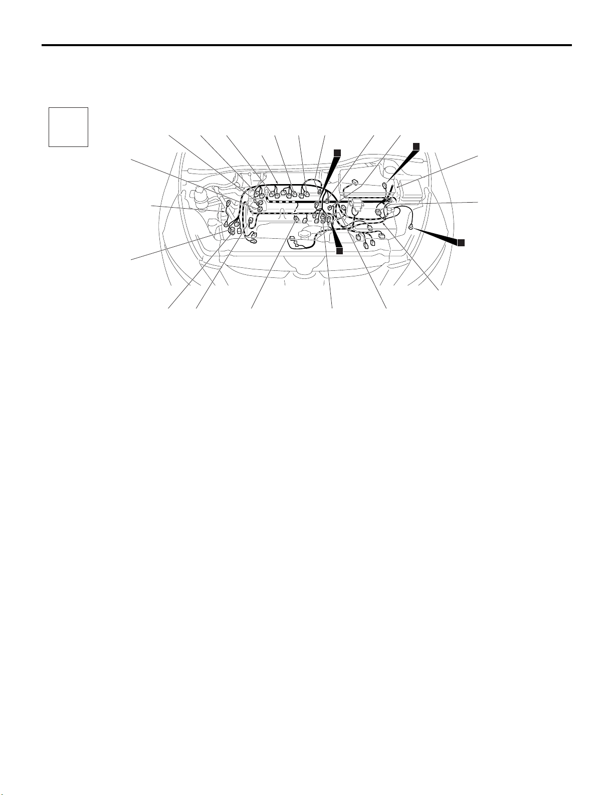
OVERALL CONFIGURATION DIAGRAM
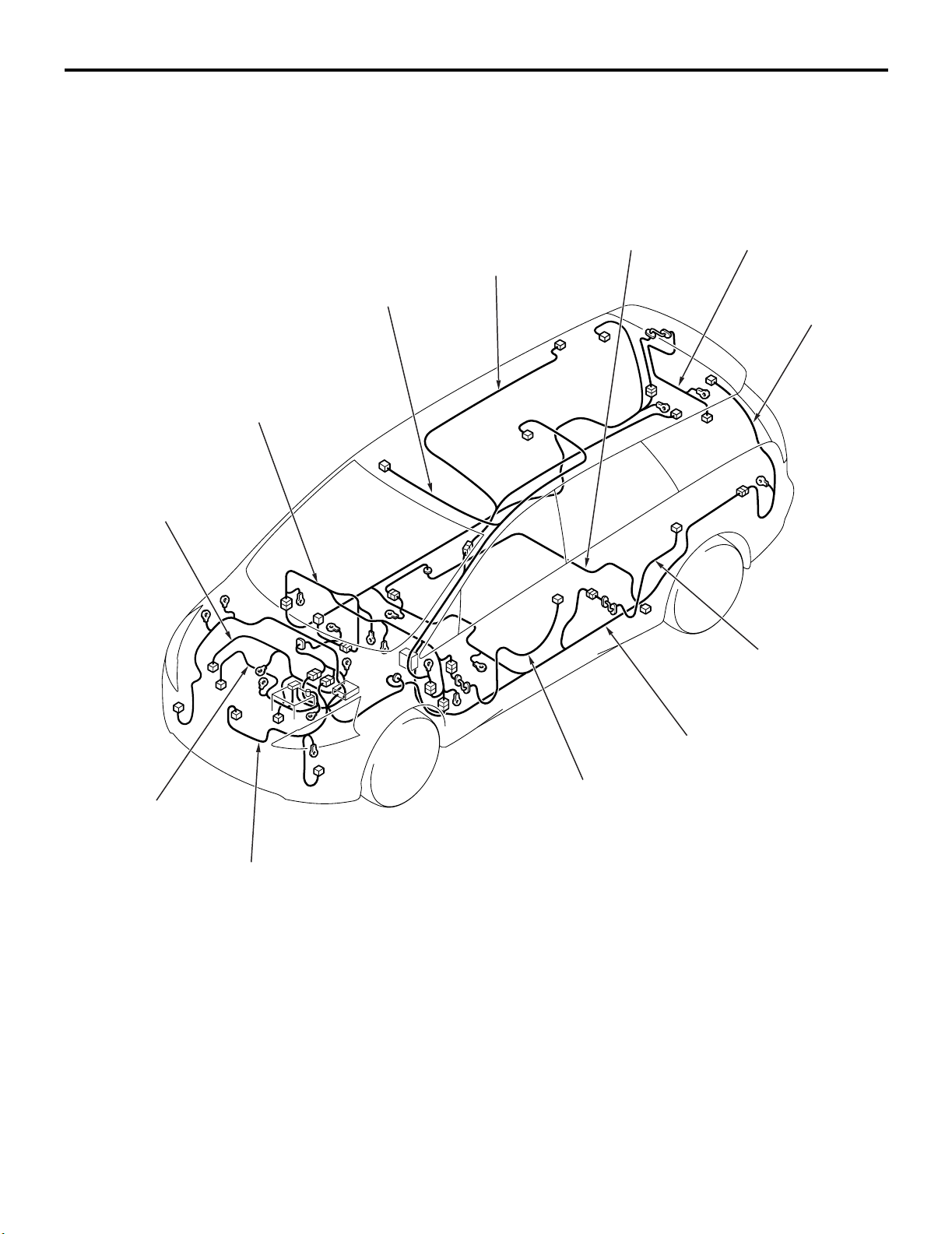
OVERALL CONFIGURATION DIAGRAM
OVERALL WIRING DIAGRAM <LHD>
M1801000100699
Roof wiring
harness
Instrument panel
wiring harness
Control wiring
harness
Room lamp
wiring harness
Fuel wiring
harness
Tailgate wiring
harness
Rear floor
wiring harness
Battery wiring
harness
Front wiring
harness
NOTE: .
1. This illustration shows only major wiring harnesses.
2. *: also equipped at the right side.
Front door
wiring harness
Floor wiring
harness
*
Rear door
wiring harness
AC310351
*
AB
Page 3
CONFIGURATION DIAGRAMS
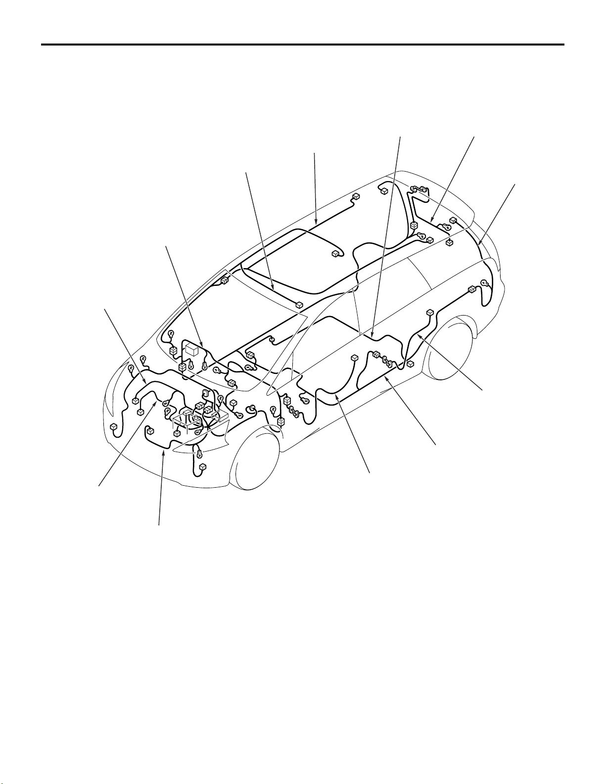
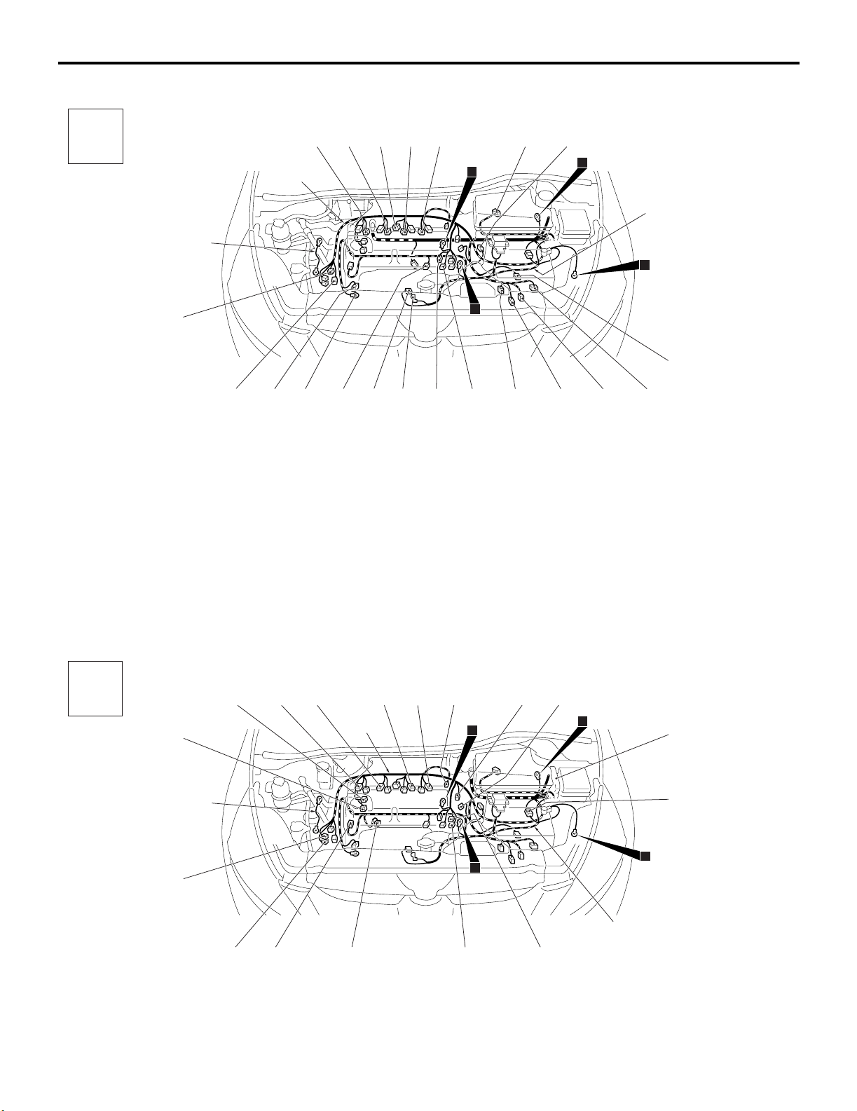
OVERALL CONFIGURATION DIAGRAM
80-3
OVERALL WIRING DIAGRAM <RHD>
M1801000100707
Roof wiring
harness
Instrument panel
wiring harness
Control wiring
harness
Room lamp
wiring harness
Fuel wiring
harness
Tailgate wiring
harness
Rear floor
wiring harness
Battery wiring
harness
Front wiring
harness
NOTE: .
1. This illustration shows only major wiring harnesses.
2. *: also equipped at the right side.
Front door
wiring harness
*
Floor wiring
harness
Rear door
wiring harness
*
AC310352
AB
Page 4
80-4
CONFIGURATION DIAGRAMS
ENGINE COMPARTMENT
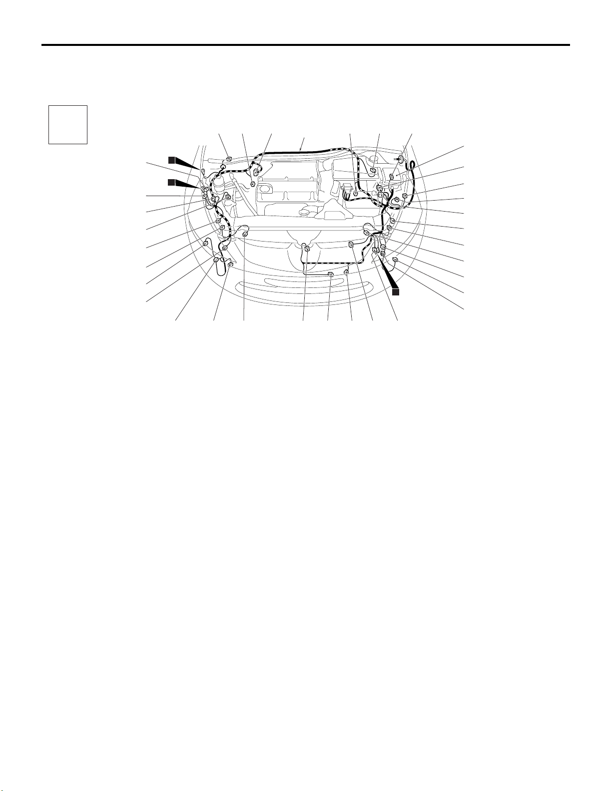
ENGINE COMPARTMENT
ENGINE COMPARTMENT <LHD>
M1801000301113
Connector
symbol
A-01
A-31
A-02
A-30
A
A-40
A-39
A-38
A-37
A-36
Connector colour code
B : Black
BR : Brown
G : Green
GR : Gray
L : Blue
None : Milk white
O : Orange
R : Red
V : Violet
Y : Yellow
A-35
A-34
A-33
A-01 (5-GR) Windshield wiper motor
A-02 (2-GR) Wheel speed sensor (Front: RH)
A-03 (26) ABS-ECU <Vehicles without ASC>
A-04 (47) ASC-ECU <Vehicles with ASC>
A-05 (2-GR) Wheel speed sensor (Front: LH)
A-06 (2-GR) Brake fluid level indicator switch
A-07 (6) J/C (CAN 1)
A-08X (4) Front fog lamp relay
A-09X (4) Horn relay
A-13X (4) Fan control relay
A-14X (11) Front-ECU
A-15X (11) Front-ECU
A-16 (12-B) Front wiring harness and control
wiring harness combination
A-17 (2-GR) Position lamp (LH)
A-18 (2-B) Headlamp (LO: LH)
A-19 (4-B) Front wiring harness and battery
wiring harness combination
A-20 (3-GR) Headlamp leveling unit (LH)
A-21 (2-GR) Headlamp (HI: LH)
2
1
A-32
A-03
A-04
Front wiring
harness
A-29
A-28
A-05
A-27
A-06
A-26
11
A-25
A-07
A-08X A-09X
A-13X A-14X
A-15X
A-16
A-17
A-18
A-19
A-20
A-21
A-22
A-23
A-24
A-41
A-22 (2-Y) Front impact sensor (LH)
A-23 (2-B) Front turn-signal lamp (LH)
A-24 (2-B) Front fog lamp (LH)
A-25 (6-GR) Earth
A-26 (3-GR) Fan controller
A-27 (1-B) Horn (LO)
A-28 (2-B) Ambient temperature sensor
A-29 (1-B) Horn (HI)
A-30 (2-Y) Front impact sensor (RH)
A-31 (2-GR) Headlamp washer motor
A-32 (2-B) Front fog lamp (RH)
A-33 (2-B) Front turn-signal lamp (RH)
A-34 (2-GR) Washer motor
A-35 (2-GR) Headlamp (HI: RH)
A-36 (3-GR) Headlamp leveling unit (RH)
A-37 (3-B) A/C pressure sensor
A-38 (2-B) Headlamp (LO: RH)
A-39 (2-GR) Position lamp (RH)
A-40 (6-GR) Earth
A-41 (4-B) Spare connector (For trailer)
AC310245
AB
Page 5
CONFIGURATION DIAGRAMS
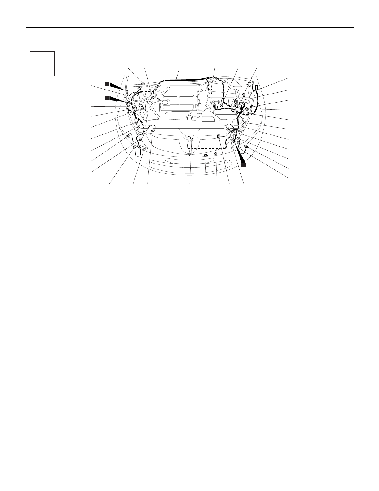
ENGINE COMPARTMENT
80-5
ENGINE COMPARTMENT <RHD>
M1801000301124
Connector
symbol
A-02
A-06
A
A-40
A-39
A-38
A-37
A-36
Connector colour code
B : Black
BR : Brown
G : Green
GR : Gray
L : Blue
None : Milk white
O : Orange
R : Red
V : Violet
Y : Yellow
A-35
A-34
A-33
A-01 (5-GR) Windshield wiper motor
A-02 (2-GR) Wheel speed sensor (Front: RH)
A-03 (26) ABS-ECU <Vehicles without ASC>
A-04 (47) ASC-ECU <Vehicles with ASC>
A-05 (2-GR) Wheel speed sensor (Front: LH)
A-06 (2-GR) Brake fluid level indicator switch
A-07 (6) J/C (CAN 1)
A-08X (4) Front fog lamp relay
A-09X (4) Horn relay
A-13X (4) Fan control relay
A-14X (11) Front-ECU
A-15X (11) Front-ECU
A-16 (12-B) Front wiring harness and control
wiring harness combination
A-17 (2-GR) Position lamp (LH)
A-18 (2-B) Headlamp (LO: LH)
A-19 (4-B) Front wiring harness and battery
wiring harness combination
A-20 (3-GR) Headlamp leveling unit (LH)
A-21 (2-GR) Headlamp (HI: LH)
2
1
A-32
A-01
A-31
A-30
Front wiring
harness
A-29
A-28
A-03
A-04
A-27
A-26
A-05
11
A-25
A-07
A-08X A-09X
A-13X A-14X
A-15X
A-16
A-17
A-18
A-19
A-20
A-21
A-22
A-23
A-24
A-41
A-22 (2-Y) Front impact sensor (LH)
A-23 (2-B) Front turn-signal lamp (LH)
A-24 (2-B) Front fog lamp (LH)
A-25 (6-GR) Earth
A-26 (3-GR) Fan controller
A-27 (1-B) Horn (LO)
A-28 (2-B) Ambient temperature sensor
A-29 (1-B) Horn (HI)
A-30 (2-Y) Front impact sensor (RH)
A-31 (2-GR) Headlamp washer motor
A-32 (2-B) Front fog lamp (RH)
A-33 (2-B) Front turn-signal lamp (RH)
A-34 (2-GR) Washer motor
A-35 (2-GR) Headlamp (HI: RH)
A-36 (3-GR) Headlamp leveling unit (RH)
A-37 (3-B) A/C pressure sensor
A-38 (2-B) Headlamp (LO: RH)
A-39 (2-GR) Position lamp (RH)
A-40 (6-GR) Earth
A-41 (4-B) Spare connector (For trailer)
AC310248
AB
Page 6
80-6
CONFIGURATION DIAGRAMS
ENGINE AND TRANSMISSION
ENGINE AND TRANSMISSION
ENGINE AND TRANSMISSION <LHD>
M1801000400935
Connector
symbol
-01
thru
B
-24
B-24
Earth cable
B-23
B-01 (2-B) Purge control solenoid valve
B-02 (3-GR) Ignition coil 1
B-03 (3-GR) Ignition coil 2
B-04 (3-GR) Ignition coil 3
B-05 (3-GR) Ignition coil 4
B-06 (6-B) Electronic-controlled throttle valve
B-07 (2-B) Engine oil control valve
B-08 (2-B) Engine coolant temperature sensor
B-12X (4) Throttle valve control servo relay
B-14X (4) A/T control relay
B-15X (4) Engine control relay
B-16X (4) A/C compressor relay
B-17 (8-B) Control wiring harness and battery
wiring harness combination
B-22
B-01
B-02
B-03
Control wiring
harness
B-20B-21
B-04
B-05
B-06
3
9
B-19
B-07
B-18
B-08
12
Battery wiring
harness
B-12X B-14X
B-15X B-16X
B-17
10
B-18 (4-B) Cylinder 2, 3 heated oxygen sensor
(Rear)
B-19 (4-GR) Cylinder 2, 3 heated oxygen sensor
(Front)
B-20 (3-B) Power steering fluid pressure sensor
B-21 (2-B) Engine oil pan oil level sensor
B-22 (4-GR) Cylinder 1, 4 heated oxygen sensor
(Front)
B-23 (4-B) Cylinder 1, 4 heated oxygen sensor
(Rear)
B-24 (2-GR) Detonation sensor
Connector colour code
B : Black
BR : Brown
G : Green
GR : Gray
L : Blue
None : Milk white
O : Orange
R : Red
V : Violet
Y : Yellow
AC310306
AB
Page 7
CONFIGURATION DIAGRAMS
ENGINE AND TRANSMISSION
ENGINE AND TRANSMISSION <LHD> (CONTINUED)
Connector
symbol
B
-101
thru
-121
Earth cable
B-101
Control wiring
harness
B-102
B-103
B-104
B-105
80-7
B-107
B-106
3
12
Battery wiring
harness
10
B-121
B-120
B-119
B-118
B-117
B-116
B-101 (2-GR) Injector 1
B-102 (2-GR) Injector 2
B-103 (6-GR) Exhaust gas recirculation valve
B-104 (2-GR) Injector 3
B-105 (2-GR) Injector 4
B-106 (4-GR) Air flow sensor
B-107 (3-B) Vehicle speed sensor <M/T>
B-108 (3-GR) Output shaft speed sensor <A/T>
B-109 (10-GR) A/T control solenoid valve assembly
B-110 (2-B) Back-up lamp switch <M/T>
B-111 (10-B) Inhibitor switch <A/T>
B-112 (3-B) Input shaft speed sensor <A/T>
Connector
symbol
-01
thru
B
-24
B-24
B-01
B-02
B-03
Control wiring
harness
B-04
B-115
9
B-108
B-114
B-113
B-112
B-111
B-110
B-109
B-113 (1-B) Capacitor
B-114 (3-B) Camshaft position sensor
B-115 (1) Starter
B-116 (1-B) Starter
B-117 (1-B) Engine oil pressure switch
B-118 (1) Alternator
B-119 (4-GR) Alternator
B-120 (1-B) A/C compressor assembly
B-121 (3-GR) Crank angle sensor
ENGINE AND TRANSMISSION <RHD>
B-06
B-05
3
B-07
B-08
12
B-12X B-14X
B-15X B-16X
Connector colour code
B : Black
BR : Brown
G : Green
GR : Gray
L : Blue
None : Milk white
O : Orange
R : Red
V : Violet
Y : Yellow
AC310306
M1801000400946
AC
Earth cable
B-23
B-22
B-01 (2-B) Purge control solenoid valve
B-02 (3-GR) Ignition coil 1
B-03 (3-GR) Ignition coil 2
B-04 (3-GR) Ignition coil 3
B-17
9
Battery wiring
harness
B-20B-21
B-19
B-18
10
Connector colour code
B : Black
BR : Brown
G : Green
GR : Gray
L : Blue
None : Milk white
O : Orange
R : Red
V : Violet
Y : Yellow
AC310309
AB
B-05 (3-GR) Ignition coil 4
B-06 (6-B) Electronic-controlled throttle valve
B-07 (2-B) Engine oil control valve
B-08 (2-B) Engine coolant temperature sensor
B-12X (4) Throttle valve control servo relay
Page 8

80-8
CONFIGURATION DIAGRAMS
ENGINE AND TRANSMISSION
B-14X (4) A/T control relay
B-15X (4) Engine control relay
B-16X (4) A/C compressor relay
B-17 (8-B) Control wiring harness and battery
wiring harness combination
B-18 (4-B) Cylinder 2, 3 heated oxygen sensor
(Rear)
B-19 (4-GR) Cylinder 2, 3 heated oxygen sensor
(Front)
B-20 (3-B) Power steering fluid pressure sensor
B-21 (2-B) Engine oil pan oil level sensor
B-22 (4-GR) Cylinder 1, 4 heated oxygen sensor
(Front)
B-23 (4-B) Cylinder 1, 4 heated oxygen sensor
(Rear)
B-24 (2-GR) Detonation sensor
ENGINE AND TRANSMISSION <RHD> (CONTINUED)
Connector
symbol
-101
thru
B
-121
Control wiring
harness
B-101
B-102
B-103
B-104
B-105
B-107
B-106
3
12
Earth cable
B-121
B-120
B-119
B-118
B-117
B-116
B-101 (2-GR) Injector 1
B-102 (2-GR) Injector 2
B-103 (6-GR) Exhaust gas recirculation valve
B-104 (2-GR) Injector 3
B-105 (2-GR) Injector 4
B-106 (4-GR) Air flow sensor
B-107 (3-B) Vehicle speed sensor <M/T>
B-108 (3-GR) Output shaft speed sensor <A/T>
B-109 (10-GR) A/T control solenoid valve assembly
B-110 (2-B) Back-up lamp switch <M/T>
B-111 (10-B) Inhibitor switch <A/T>
B-115
Battery wiring
harness
10
9
Connector colour code
B : Black
BR : Brown
G : Green
GR : Gray
L : Blue
None : Milk white
O : Orange
R : Red
V : Violet
Y : Yellow
B-114
B-113
B-112
B-111
B-110
B-108
B-109
B-112 (3-B) Input shaft speed sensor <A/T>
B-113 (1-B) Capacitor
B-114 (3-B) Camshaft position sensor
B-115 (1) Starter
B-116 (1-B) Starter
B-117 (1-B) Engine oil pressure switch
B-118 (1) Alternator
B-119 (4-GR) Alternator
B-120 (1-B) A/C compressor assembly
B-121 (3-GR) Crank angle sensor
AC310309
AC
Page 9

CONFIGURATION DIAGRAMS
DASH PANEL
DASH PANEL
80-9
DASH PANEL <LHD>
M1801000600887
Connector
symbol
C
-01
thru
-39
C-32
C-31
C-30
C-29
C-28
C-27
C-26
C-39
C-25
Roof wiring
harness
Floor wiring
harness
C-01 (33) J/C (6)
C-02 (40) Combination meter
C-03 (5) Photo sensor
C-04 (7-GR) Mode selection damper control motor
and potentiometer
C-05 (2) Air thermo sensor
C-06 (16-B) Centre display
C-07 (20-B) Centre display
C-08 (2) Glove box lamp
C-09 (22-GR) J/C (CAN 2)
C-10 (3) Outside/ inside air selection damper
control motor
C-11 (7) Front air mixing damper control motor
and potentiometer
C-12 (4) Front power transistor
C-13 (2) Front blower motor
C-14 (32) Instrument panel wiring harness and
front door wiring harness (RH)
combination
C-15 (38) Instrument panel wiring harness and
floor wiring harness combination
C-16 (43) Instrument panel wiring harness and
floor wiring harness combination
C-17 (18) Instrument panel wiring harness and
control wiring harness combination
C-01
C-02
15
C-23 C-22
C-24
C-03
C-04
C-05
14
13
C-21
C-20
C-06 C-07
C-19
C-37
C-38
C-18
C-08
C-09
Y
5
C-16 C-15
C-17
C-10
C-11
Instrument panel
wiring harness
4
C-12
Control wiring
harness
C-13
C-14
Connector colour code
B : Black
BR : Brown
G : Green
GR : Gray
L : Blue
None : Milk white
O : Orange
R : Red
V : Violet
Y : Yellow
AC310236
C-18 (10) Instrument panel wiring harness and
control wiring harness combination
C-19 (6-GR) Rear fan switch
C-20 (14) Radio and CD player
C-21 (2) Ashtray illumination lamp
C-22 (14) Radio and CD player
C-23 (1-B) Radio and CD player
C-24 (1) Glass antenna amp
C-25 (3) Passenger’s air bag off indicator lamp
C-26 (2) Interior temperature sensor
C-27 (32) Instrument panel wiring harness and
front door wiring harness (LH)
combination
C-28 (6-B) TCL off switch
C-29 (6-GR) Headlamp leveling switch
C-30 (6) PTC heater switch
C-31 (33) J/C (5)
C-32 (33) J/C (7)
C-37 (10) Jumper connector
C-38 (10) Spare connector (For navigation
system)
C-39 (4) Spare connector (For trailer)
AB
Page 10

80-10
DASH PANEL <LHD> (CONTINUED)
Connector
symbol
C
-101
thru
-131
Roof wiring
harness
C-101
C-102
CONFIGURATION DIAGRAMS
DASH PANEL
C-106
C-103
C-104
C-105
C-107
C-108
C-109
C-131
C-130
C-129
C-128
C-127
C-121
14
C-120
C-119
13
C-118
C-126
C-125
C-124
15
Floor wiring
harness
C-123
C-122
C-101 (2) Jumper connector <Vehicles with
DRL> or No connection <Vehicles
without DRL>
C-102 (6-B) Accelerator pedal position sensor
C-103 (4) PTC heater
C-104 (22) A/C-ECU
C-105 (16) A/C-ECU
C-106 (26) A/C-ECU
C-107 (4) Passenger’s air bag cut off switch
C-108 (4-Y) Air bag module (squib) <Passenger’s
side>
C-109 (6) Engine oil level relay
C-110 (27-GR) Engine-ECU <M/T> or
Engine-A/T-ECU <A/T>
C-111 (28-GR) Engine-ECU <M/T> or
Engine-A/T-ECU <A/T>
C-112 (29-GR) Engine-ECU <M/T> or
Engine-A/T-ECU <A/T>
C-113 (30-GR) Engine-ECU <M/T> or
Engine-A/T-ECU <A/T>
C-114 (26-GR) Engine-ECU <M/T> or
Engine-A/T-ECU <A/T>
Control wiring
harness
Instrument panel
wiring harness
4
C-110
C-111
C-112
C-113
C-114
Connector colour code
B : Black
BR : Brown
G : Green
GR : Gray
L : Blue
None : Milk white
O : Orange
R : Red
V : Violet
Y : Yellow
C-117
C-116
Y
5
C-115
C-115 (11) Earth
C-116 (33) J/C (4)
C-117 (6) G and yaw rate sensor
C-118 (20-Y) SRS-ECU
C-119 (28-Y) SRS-ECU
C-120 (20-Y) SRS-ECU
C-121 (6) Shift switch assembly
C-122 (2) A/T selector lever position illumination
lamp
C-123 (4) Hazard warning lamp switch
C-124 (43) Instrument panel wiring harness and
front wiring harness combination
C-125 (38) Instrument panel wiring harness and
front wiring harness combination
C-126 (16-B) Diagnosis connector
C-127 (4) Stop lamp switch
C-128 (25) Instrument panel wiring harness and
roof wiring harness combination
C-129 (11) Remote controlled mirror switch
C-130 (6) Fog lamp switch
C-131 (2) Clutch switch <Auto-cruise (M/T) >
AC310236
AC
Page 11

DASH PANEL <LHD> (CONTINUED)
Connector
symbol
C
-201
thru
-221
C-201
<J/B (Front view) >
C-202
CONFIGURATION DIAGRAMS
DASH PANEL
C-203
C-204
80-11
<J/B (Rear view) >
C-219
C-218
C-217
C-216
C-215
C-214
C-213
C-212
C-211
C-210
C-205
C-206
C-207
C-208
C-209
C-201 (13) Instrument panel wiring harness and
J/B combination
C-202 (6) Instrument panel wiring harness and
J/B combination
C-203 (14) Instrument panel wiring harness and
J/B combination
C-204 (1-B) Instrument panel wiring harness and
J/B combination
C-205 (28) Instrument panel wiring harness and
J/B combination
C-206 (5) PTC heater relay 1
C-207 (5) PTC heater relay 2
C-208 (5) Rear window defogger relay
C-209 (5) Front blower relay
C-221
C-220
C-210 (15) Floor wiring harness and J/B
combination
C-211 (3) Roof wiring harness and J/B
combination
C-212 (4) Heated seat relay
C-213 (4) Rear fog lamp relay
C-214 (4) Fuel pump relay 2
C-215 (4) Rear blower relay
C-216 (4) Fuel pump relay 1
C-217 (5) Power window relay
C-218 (2) No connection
C-219 (20) ETACS-ECU
C-220 (24) ETACS-ECU
C-221 (24-GR) ETACS-ECU
Connector colour
code
B : Black
BR : Brown
G : Green
GR : Gray
L : Blue
None : Milk white
O : Orange
R : Red
V : Violet
Y : Yellow
AC310815
AB
Page 12

80-12
DASH PANEL <LHD> (CONTINUED)
Connector
symbol
-301
C
thru
-311
CONFIGURATION DIAGRAMS
DASH PANEL
<Steering column>
Clock spring
C-301
C-302
C-303
C-304
C-305
C-306
Instrument panel
wiring harness
C-307
Y
Connector colour code
Black
B :
BR : Brown
G :
Green
Gray
GR :
L :
Blue
None : Milk white
O :
R :
V :
Y :
Orange
Red
Violet
Yellow
C-311
C-301 (10) Column switch
C-302 (1) Horn switch
C-303 (4-Y) Air bag module (squib) <Driver’s side>
C-304 (3-B) Clock spring sub wiring harness and
auto-cruise control switch sub wiring
harness combination
C-305 (3-Y) Auto-cruise control switch
C-310
C-309
C-308
AC309925
C-306 (5) Steering wheel sensor
C-307 (6) Ignition switch
C-308 (7) Key reminder switch
C-309 (4-Y) Clock spring
C-310 (6-B) Clock spring
C-311 (5) Clock spring and clock spring sub wiring
harness combination
AB
Page 13

CONFIGURATION DIAGRAMS
DASH PANEL
80-13
DASH PANEL <RHD>
M1801000600898
Connector
symbol
-01
thru
C
-39
C-13
Instrument panel
wiring harness
Front wiring
harness
C-27
C-39
Control wiring
harness
C-01 (33) J/C (6)
C-02 (40) Combination meter
C-03 (5) Photo sensor
C-04 (7-GR) Mode selection damper control motor
and potentiometer
C-05 (2) Air thermo sensor
C-06 (16-B) Centre display
C-07 (20-B) Centre display
C-08 (2) Glove box lamp
C-09 (22-GR) J/C (CAN 2)
C-10 (3) Outside/ inside air selection damper
control motor
C-11 (7) Front air mixing damper control motor
and potentiometer
C-12 (4) Front power transistor
C-13 (2) Front blower motor
C-14 (32) Instrument panel wiring harness and
front door wiring harness (RH)
combination
C-15 (38) Instrument panel wiring harness and
floor wiring harness combination
C-16 (43) Instrument panel wiring harness and
floor wiring harness combination
C-17 (18) Instrument panel wiring harness and
control wiring harness combination
C-12
C-11
C-09
C-08
C-10
15
C-17
C-38
Y
5
C-18
C-37
C-24
C-06
C-07
C-23
13
C-04
C-05
C-22 C-21
C-02 C-26
C-03
14
C-20
C-19
C-30
Roof wiring
harness
4
C-25
C-01
C-33
C-31
C-28
C-29
C-14
C-34
C-35
C-36
C-15
C-16
Connector colour code
B : Black
BR : Brown
G : Green
GR : Gray
L : Blue
None : Milk white
O : Orange
R : Red
V : Violet
Y : Yellow
C-18 (10) Instrument panel wiring harness and
control wiring harness combination
C-19 (6-GR) Rear fan switch
C-20 (14) Radio and CD player
C-21 (2) Ashtray illumination lamp
C-22 (14) Radio and CD player
C-23 (1-B) Radio and CD player
C-24 (1) Glass antenna amp
C-25 (3) Passenger’s air bag off indicator lamp
C-26 (2) Interior temperature sensor
C-27 (32) Instrument panel wiring harness and
front door wiring harness (LH)
combination
C-28 (6-B) TCL off switch
C-29 (6-GR) Headlamp leveling switch
C-30 (6) PTC heater switch
C-31 (33) J/C (5)
C-33 (22) J/C (7)
C-34 (1-B) Cigarette lighter
C-35 (1) Cigarette lighter
C-36 (2) Cigarette lighter illumination lamp
C-37 (10) Jumper connector
C-38 (10) Spare connector (For navigation
system)
C-39 (4) Spare connector (For trailer)
AC310239
AB
Page 14

80-14
DASH PANEL <RHD> (CONTINUED)
Connector
symbol
-102
thru
C
-131
C-109
CONFIGURATION DIAGRAMS
DASH PANEL
C-107
C-108
C-104
C-105
C-106
C-103
Roof wiring
harness
Instrument panel
wiring harness
Front wiring
harness
Control wiring
harness
C-125
15
C-124
C-110
C-111
C-112
C-113
5
C-115
C-102 (6-B) Accelerator pedal position sensor
C-103 (4) PTC heater
C-104 (22) A/C-ECU
C-105 (16) A/C-ECU
C-106 (26) A/C-ECU
C-107 (4) Passenger’s air bag cut off switch
C-108 (4-Y) Air bag module (squib) <Passenger’s
side>
C-109 (6) Engine oil level relay
C-110 (27-GR) Engine-ECU <M/T> or
Engine-A/T-ECU <A/T>
C-111 (28-GR) Engine-ECU <M/T> or
Engine-A/T-ECU <A/T>
C-112 (29-GR) Engine-ECU <M/T> or
Engine-A/T-ECU <A/T>
C-113 (30-GR) Engine-ECU <M/T> or
Engine-A/T-ECU <A/T>
C-114 (26-GR) Engine-ECU <M/T> or
Engine-A/T-ECU <A/T>
C-115 ( 11) Earth
Y
C-114
C-116
13
C-120
C-119
14
C-118
C-117
C-121
C-122
4
C-123
C-102
C-130
C-129
C-128
C-127
C-131
C-126
C-116 (33) J/C (4)
C-117 (6) G and yaw rate sensor
C-118 (20-Y) SRS-ECU
C-119 (28-Y) SRS-ECU
C-120 (20-Y) SRS-ECU
C-121 (6) Shift switch assembly
C-122 (2) A/T selector lever position illumination
lamp
C-123 (4) Hazard warning lamp switch
C-124 (43) Instrument panel wiring harness and
front wiring harness combination
C-125 (38) Instrument panel wiring harness and
front wiring harness combination
C-126 (16-B) Diagnosis connector
C-127 (4) Stop lamp switch
C-128 (25) Instrument panel wiring harness and
roof wiring harness combination
C-129 (11) Remote controlled mirror switch
C-130 (6) Fog lamp switch
C-131 (2) Clutch switch <Auto-cruise (M/T) >
Connector colour code
B : Black
BR : Brown
G : Green
GR : Gray
L : Blue
None : Milk white
O : Orange
R : Red
V : Violet
Y : Yellow
AC310239
AC
Page 15

DASH PANEL <RHD> (CONTINUED)
Connector
symbol
C
-201
thru
-221
C-213
C-214
<J/B (Front view) >
C-215
C-206
C-207
CONFIGURATION DIAGRAMS
DASH PANEL
C-216
C-218
80-15
<J/B (Rear view) >
C-212
C-211
C-210
C-204
C-217
C-209
C-208
C-205
C-203
C-201 (13) Instrument panel wiring harness and
J/B combination
C-202 (6) Instrument panel wiring harness and
J/B combination
C-203 (14) Instrument panel wiring harness and
J/B combination
C-204 (1-B) Instrument panel wiring harness and
J/B combination
C-205 (28) Instrument panel wiring harness and
J/B combination
C-206 (5) PTC heater relay 1
C-207 (5) PTC heater relay 2
C-208 (5) Rear window defogger relay
C-209 (5) Front blower relay
C-201
C-202
C-219
Connector colour code
B : Black
BR : Brown
G : Green
GR : Gray
C-221
C-220
L : Blue
None : Milk white
O : Orange
R : Red
V : Violet
Y : Yellow
C-210 (15) Floor wiring harness and J/B
combination
C-211 (3) Roof wiring harness and J/B
combination
C-212 (4) No connection
C-213 (4) Rear fog lamp relay
C-214 (4) Fuel pump relay 2
C-215 (4) Rear blower relay
C-216 (4) Fuel pump relay 1
C-217 (5) Power window relay
C-218 (2) No connection
C-219 (20) ETACS-ECU
C-220 (24) ETACS-ECU
C-221 (24-GR) ETACS-ECU
AC310816
AB
Page 16

80-16
DASH PANEL <RHD> (CONTINUED)
Connector
symbol
-301
C
thru
-311
CONFIGURATION DIAGRAMS
DASH PANEL
<Steering column>
C-302
Clock spring
C-301
Instrument panel
wiring harness
C-307
C-306
C-308
C-301 (10) Column switch
C-302 (1) Horn switch
C-303 (4-Y) Air bag module (squib) <Driver’s side>
C-304 (3-B) Clock spring sub wiring harness and
auto-cruise control switch sub wiring
harness combination
C-305 (3-Y) Auto-cruise control switch
Y
C-310
C-303
C-304
C-309
C-305
C-311
Connector colour
code
B : Black
BR : Brown
G : Green
GR : Gray
L : Blue
None : Milk white
O : Orange
R : Red
V : Violet
Y : Yellow
AC309928
C-306 (5) Steering wheel sensor
C-307 (6) Ignition switch
C-308 (7) Key reminder switch
C-309 (4-Y) Clock spring
C-310 (6-B) Clock spring
C-311 (5) Clock spring and clock spring sub wiring
harness combination
AB
Page 17

CONFIGURATION DIAGRAMS
FLOOR
FLOOR
80-17
FLOOR <LHD>
M1801003500016
Connector
symbol
D-01
D-02
D-03
D-04
D-05
D
D-32
D-31
D-30
D-25
D-24
Y
Y
6
D-23
D-29
D-28
D-34
D-27
D-26
D-01 (2-Y) Side impact sensor (Front: RH)
D-02 (3) Door switch (Front: RH)
D-03 (10-B) Floor wiring harness and rear door
wiring harness (RH) combination
D-04 (9) Heated seat switch
D-05 (2) Cigarette lighter illumination lamp
D-06 (2-B) Wheel speed sensor (Rear: RH)
D-07 (2) Fuel tank gauge unit
D-08 (3) Door switch (Rear: RH)
D-09 (2-Y) Side impact sensor (Rear: RH)
D-10 (2) Rear blower motor
D-11 (4) Rear power transistor
D-12 (2-Y) Side impact sensor (Rear: LH)
D-13 (3) Door switch (Rear: LH)
D-14 (2-B) Wheel speed sensor (Rear: LH)
D-15 (5-GR) Fuel tank pump and gauge unit
assembly
D-16 (10) Floor wiring harness and rear door
wiring harness (LH) combination
D-17 (3) Door switch (Front: LH)
D-06
D-08
D-07
Y
17
D-22
D-21
D-20
D-09
Fuel wiring
harness
Y
D-19
D-10
D-18
D-11
D-17
Floor wiring
harness
D-16
D-12
D-13
D-14
D-15
Connector colour code
B : Black
BR : Brown
G : Green
GR : Gray
L : Blue
None : Milk white
O : Orange
R : Red
V : Violet
Y : Yellow
AC309785
AB
D-18 (2-Y) Side impact sensor (Front: LH)
D-19 (2-B) Seat belt pre-tensioner (LH)
D-20 (3-B) Heated seat (LH)
D-21 (2-GR) Seat slide sensor (LH)
D-22 (2-R) Side air bag module (squib) (LH)
D-23 (2) Seat belt switch (LH)
D-24 (1-B) Parking brake switch
D-25 (10-GR) Floor wiring harness and console
wiring harness combination
D-26 (2) Seat belt switch (RH)
D-27 (3-B) Heated seat (RH)
D-28 (13) Floor wiring harness and fuel wiring
harness combination
D-29 (2-R) Side air bag module (squib) (RH)
D-30 (1) Cigarette lighter
D-31 (1-B) Cigarette lighter
D-32 (2-B) Seat belt pre-tensioner (RH)
D-34 (8-B) Spare connector (For navigation
system)
Page 18

80-18
CONFIGURATION DIAGRAMS
FLOOR
FLOOR <RHD>
M1801003500038
Connector
symbol
D-01
D-02
D-03
D-06
D
D-32
D-26
Y
Y
6
D-24
D-29
D-33
D-28
D-34
D-01 (2-Y) Side impact sensor (Front: RH)
D-02 (3) Door switch (Front: RH)
D-03 (10-B) Floor wiring harness and rear door
wiring harness (RH) combination
D-06 (2-B) Wheel speed sensor (Rear: RH)
D-07 (2) Fuel tank gauge unit
D-08 (3) Door switch (Rear: RH)
D-09 (2-Y) Side impact sensor (Rear: RH)
D-10 (2) Rear blower motor
D-11 (4) Rear power transistor
D-12 (2-Y) Side impact sensor (Rear: LH)
D-13 (3) Door switch (Rear: LH)
D-14 (2-B) Wheel speed sensor (Rear: LH)
D-15 (5-GR) Fuel tank pump and gauge unit
assembly
D-16 (10) Floor wiring harness and rear door
wiring harness (LH) combination
D-23
D-18
D-11
D-17
Floor wiring
harness
D-16
D-12
D-13
D-14
D-15
D-07
D-10
D-22
D-09
Fuel wiring
harness
Y
D-19
D-08
Y
17
D-17 (3) Door switch (Front: LH)
D-18 (2-Y) Side impact sensor (Front: LH)
D-19 (2-B) Seat belt pre-tensioner (LH)
D-22 (2-R) Side air bag module (squib) (LH)
D-23 (2) Seat belt switch (LH)
D-24 (1-B) Parking brake switch
D-26 (2) Seat belt switch (RH)
D-28 (13) Floor wiring harness and fuel wiring
harness combination
D-29 (2-R) Side air bag module (squib) (RH)
D-32 (2-B) Seat belt pre-tensioner (RH)
D-33 (2-GR) Seat slide sensor (RH)
D-34 (8-B) Spare connector (For navigation
system)
Connector colour code
B : Black
BR : Brown
G : Green
GR : Gray
L : Blue
None : Milk white
O : Orange
R : Red
V : Violet
Y : Yellow
AC309788
AB
Page 19

CONFIGURATION DIAGRAMS
ROOF
ROOF
80-19
ROOF <LHD>
M1801003600013
Connector
symbol
E
E-01
Connector colour code
B : Black
BR : Brown
G : Green
GR : Gray
L : Blue
None : Milk white
O : Orange
R : Red
V : Violet
Y : Yellow
E-01 (2) Vanity mirror lamp (RH)
E-02 (10) Room lamp
E-03 (20) Rear heater controller
E-04 (3) Rear personal lamp (for second seat:
RH)
E-05 (3) Sunroof switch
E-06 (3) Rear personal lamp (for third seat:
RH)
E-07 (10) Sunroof motor assembly
E-02
E-11
<Vehicles without sunroof>
E-03
E-04
16
E-10
E-06
Roof wiring
harness
E-09
E-08
Room lamp
wiring harness
<Vehicles with sunroof>
E-01 E-02
E-11
E-03
E-04
16
E-05
E-10
Roof wiring
harness
E-06
E-07
Room lamp
wiring harness
E-09
E-08
AC310817
E-08 (3) Rear personal lamp (for third seat: LH)
E-09 (3) Rear personal lamp (for second seat:
LH)
E-10 (2) Vanity mirror lamp (LH)
E-11 (6) Roof wiring harness and room lamp
wiring harness combination
ROOF < RHD >
M1801003600035
AB
Connector
symbol
E
Roof wiring
harness
Connector colour code
B : Black
BR : Brown
G : Green
GR : Gray
L : Blue
None : Milk white
O : Orange
R : Red
V : Violet
Y : Yellow
E-01
E-11
16
<Vehicles without sunroof>
E-02
E-04
E-03
E-10
E-06
E-09
E-08
Room lamp
wiring harness
E-01 (2) Vanity mirror lamp (RH)
E-02 (10) Room lamp
E-03 (20) Rear heater controller
E-04 (3) Rear personal lamp (for second seat:
RH)
<Vehicles with sunroof>
E-01 E-02
E-11
Roof wiring
harness
E-03
16
E-04
E-05
E-10
E-06
E-07
E-09
E-08
Room lamp
wiring harness
AC310818
E-05 (3) Sunroof switch
E-06 (3) Rear personal lamp (for third seat:
RH)
E-07 (10) Sunroof motor assembly
E-08 (3) Rear personal lamp (for third seat: LH)
AB
Page 20

80-20
CONFIGURATION DIAGRAMS
E-09 (3) Rear personal lamp (for second seat:
LH)
E-10 (2) Vanity mirror lamp (LH)
E-11 (6) Roof wiring harness and room lamp
wiring harness combination
DOOR
DOOR
DOOR <LHD>
M1801001400693
Connector
symbol
F
F-01
F-08
F-01 (6-B) Power window motor (Rear: LH)
F-02 (8-B) Power window sub switch (Rear: LH)
F-03 (2) Rear door speaker (LH)
F-04 (6-B) Door lock actuator (Front: LH)
F-05 (14-B) Power window main switch
F-06 (2) Tweeter (LH)
F-07 (10) Door mirror assembly (LH)
F-08 (6-B) Door lock actuator (Rear: LH)
F-09 (2) Door lamp (Rear: LH)
F-10 (6-B) Power window motor (Front: LH)
F-11 (2) Door lamp (Front: LH)
F-12 (2) Front door speaker (LH)
F-13 (10) Door mirror assembly (RH)
F-02
Rear door
wiring
harness (LH)
F-03
F-09
<Driver's side>
F-04
F-10
F-05
Front door
wiring
harness (LH)
F-06
F-11
F-12
<Passenger's side>
F-07
F-13
F-21
F-14
F-22
F-15
Front door
wiring
harness (RH)
F-16
F-23
F-17
F-24
F-18
F-25
F-19
Rear door
wiring
harness (RH)
F-14 (2) Tweeter (RH)
F-15 (8-B) Power window sub switch (Front: RH)
F-16 (6-B) Power window motor (Front: RH)
F-17 (6-B) Door lock actuator (Front: RH)
F-18 (8-B) Power window sub switch (Rear: RH)
F-19 (6-B) Power window motor (Rear: RH)
F-20 (6-B) Door lock actuator (Rear: RH)
F-21 (2) Front door speaker (RH)
F-22 (2) Door lamp (Front: RH)
F-23 (3-B) Door key switch
F-24 (2) Rear door speaker (RH)
F-25 (2) Door lamp (Rear: RH)
F-20
AC310819
AB
Page 21

CONFIGURATION DIAGRAMS
DOOR
80-21
DOOR <RHD>
M1801001400701
Connector
symbol
F
F-14
F-22
F-05
F-16
Front door
wiring
harness (RH)
F-13
F-21
F-01 (6-B) Power window motor (Rear: LH)
F-02 (8-B) Power window sub switch (Rear: LH)
F-03 (2) Rear door speaker (LH)
F-04 (6-B) Door lock actuator (Front: LH)
F-05 (14-B) Power window main switch
F-06 (2) Tweeter (LH)
F-07 (10) Door mirror assembly (LH)
F-08 (6-B) Door lock actuator (Rear: LH)
F-09 (2) Door lamp (Rear: LH)
F-10 (6-B) Power window motor (Front: LH)
F-11 (2) Door lamp (Front: LH)
F-12 (2) Front door speaker (LH)
F-13 (10) Door mirror assembly (RH)
<Driver's side>
F-17
F-24
F-18
F-25
F-19
Rear door
wiring
harness (RH)
F-20
<Passenger's side>
F-08
F-01
F-02
Rear door
wiring
harness (LH)
F-09
F-03
F-23
F-04
F-26
Front door
wiring
harness (LH)
F-10
F-06
F-11
F-07
F-12
AC310820
F-14 (2) Tweeter (RH)
F-16 (6-B) Power window motor (Front: RH)
F-17 (6-B) Door lock actuator (Front: RH)
F-18 (8-B) Power window sub switch (Rear: RH)
F-19 (6-B) Power window motor (Rear: RH)
F-20 (6-B) Door lock actuator (Rear: RH)
F-21 (2) Front door speaker (RH)
F-22 (2) Door lamp (Front: RH)
F-23 (3-B) Door key switch
F-24 (2) Rear door speaker (RH)
F-25 (2) Door lamp (Rear: RH)
F-26 (8-B) Power window sub switch (Front: LH)
AB
Page 22

80-22
CONFIGURATION DIAGRAMS
TAILGATE
Connector
symbol
G-01
G
Y
G-25
G-24
G-23
G-22
G-21
Connector colour code
B : Black
BR : Brown
G : Green
GR : Gray
L : Blue
None : Milk white
O : Orange
R : Red
V : Violet
Y : Yellow
G-01 (2-B) Curtain air bag module (squib) (LH)
G-02 (1-B) Rear window defogger (−)
G-03 (2) High-mounted stop lamp
G-04 (2-B) Curtain air bag module (squib) (RH)
G-05 (4) Rear wiper motor
G-06 (2) Tailgate lock release handle
G-07 (1-B) Rear window defogger (+)
G-08 (3) Tail/ stop lamp (RH)
G-09 (2-B) Rear turn-signal lamp (RH)
G-10 (2-GR) Back-up lamp <LHD>
G-11 (2-GR) Rear fog lamp <RHD>
G-12 (2) Luggage compartment lamp
G-13 (5) Rear air mixing damper control motor
and potentiometer
G-14 (14) Floor wiring harness and tailgate
wiring harness combination
G-20
Rear floor
wiring harness
18
TAILGATE
G-02
Rear window
defogger earth
M1801001900290
G-05
G-06
G-07
G-08
G-09
G-10
G-11
G-12
G-13
G-14
G-19
G-03
Tailgate wiring
harness
8
G-18 G-17
G-04
Y
Floor wiring
harness
G-16
7
G-15
G-15 (2) Licence plate lamp (RH)
G-16 (3) Tailgate key switch
G-17 (2-B) Tailgate lock actuator
G-18 (1-B) Tailgate switch
G-19 (2) Licence plate lamp (LH)
G-20 (3) Tail/ stop lamp (LH)
G-21 (10) Floor wiring harness and rear floor
wiring harness (LH) combination
G-22 (2-R) Floor wiring harness and rear floor
wiring harness (LH) combination
G-23 (2-GR) Rear fog lamp <LHD>
G-24 (2-GR) Back-up lamp <RHD>
G-25 (2-B) Rear turn-signal lamp (LH)
AC309797
AB
 Loading...