

Page 1

GRANDIS - ENGLISH - OXPE10E1
OWNER’ S MANUAL
GRANDIS
Page 2
Table of contents
Overview
General information
Locking and unlocking 1
Seat and seat belts 2
Instruments and controls 3
Starting and driving 4
For pleasant driving 5
For emergencies 6
Vehicle care 7
Maintenance 8
Specifications 9
Page 3

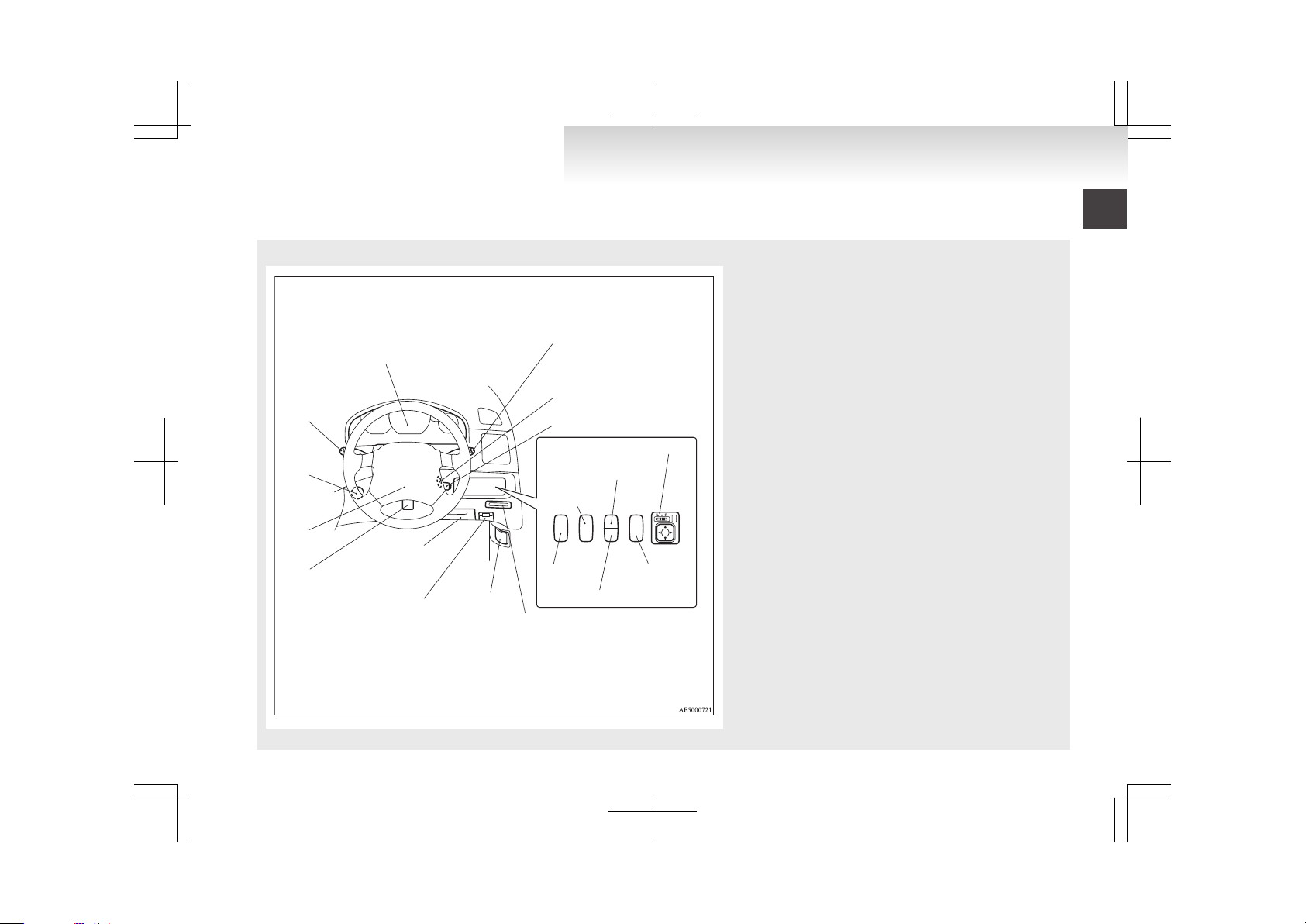
Instruments and Controls (Driver’s area)
E00100104900
LHD
1
2
3
4
5
6
7
8
9
10
11
12
13
14
17
16
15
1. Instruments p. 3-02
2. Windscreen wiper and washer switch p. 3-23
Rear window wiper and washer switch p. 3-24
3. Ignition switch p. 4-08
4. Auto-speed control lever* p. 4-25
5. Steering wheel height adjustment p. 4-06
6. Personal box p. 5-39
7. Fuel tank filler door release lever p. 03
8. Fuses p. 8-20
9. Bonnet release lever p. 8-03
10. Supplemental restraint system - airbag (for driver’s seat) p. 2-29
Horn switch p. 3-26
11. Combination headlamps and dipper switch p. 3-18
Turn signal lever p. 3-21
Headlamp washer switch* p. 3-25
12. Outside rear-view mirrors switch p. 4-07
13. Front fog lamp switch p. 3-22
14. SONAR switch* p. 4-30
15. TCL switch* p. 4-24
16. Rear fog lamp switch p. 3-22
17. Headlamp levelling switch* p. 3-19
Overview
Page 4
1
RHD
2
3
4
5
6
7
8
9
10
11
12
13
14
15
16
17
18
1. Instruments p. 3-02
2. Windscreen wiper and washer switch p. 3-23
Rear window wiper and washer switch p. 3-24
3. Ignition switch p. 4-08
4. Auto-speed control lever* p. 4-25
5. Card holder p. 5-42
6. Bonnet release lever p. 8-03
7. Fuel tank filler door release lever p. 03
8. Personal box p. 5-39
Fuses p. 8-20
9. Steering wheel height adjustment p. 4-06
10. Supplemental restraint system - airbag (for driver’s seat) p. 2-29
Horn switch p. 3-26
11. Cigarette lighter* p. 5-34
Accessory socket* p. 5-35
12. Combination headlamps and dipper switch p. 3-18
Turn signal lever p. 3-21
Headlamp washer switch* p. 3-25
13. SONAR switch* p. 4-30
14. Front fog lamp switch p. 3-22
15. Outside rear-view mirrors switch p. 4-07
16. Headlamp levelling switch* p. 3-19
17. Rear fog lamp switch p. 3-22
18. TCL switch* p. 4-24
Overview
Page 5
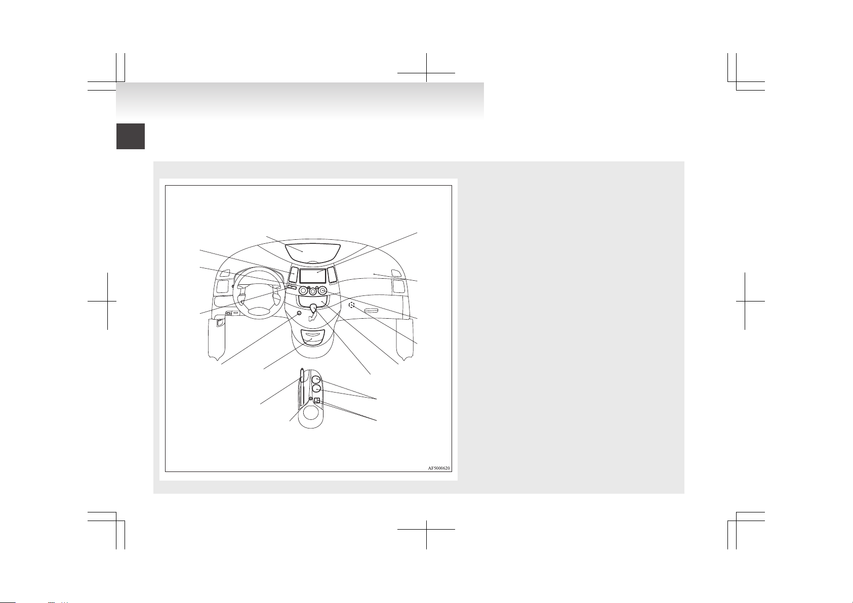
Instruments and Controls (Instrument panel)
E00100104913
LHD
1
2
3
4
5
6
7
8
9
10
11
12
13
14
15
16
1. Instrument panel upper box p. 5-39
2. Multi centre display* p. 3-09
Multi display station*
Refer to the separate “Multi display station owner’s manual”
3. Supplemental restraint system - airbag (for front passenger’s
seat) p. 2-29
4. Front automatic air conditioning p. 5-05
5. Front passenger’s airbag ON-OFF switch p. 2-33
6. Audio p. 5-13
7. Gearshift or selector lever p. 4-13, 4-15
8. Cup holder (for front seats) p. 5-40
9. Heated seat switch* p. 2-06
10. Cigarette lighter* p. 5-34
Accessory socket* p. 5-35
11. Parking brake lever p. 4-04
12. Ashtray (fixed position) p. 5-33
13. Hazard warning flasher switch p. 3-21
14. Front passenger’s airbag OFF indication lamp p. 2-34
15. Rear window demister switch p. 3-25
16. Ventilators p. 5-02
Overview
Page 6
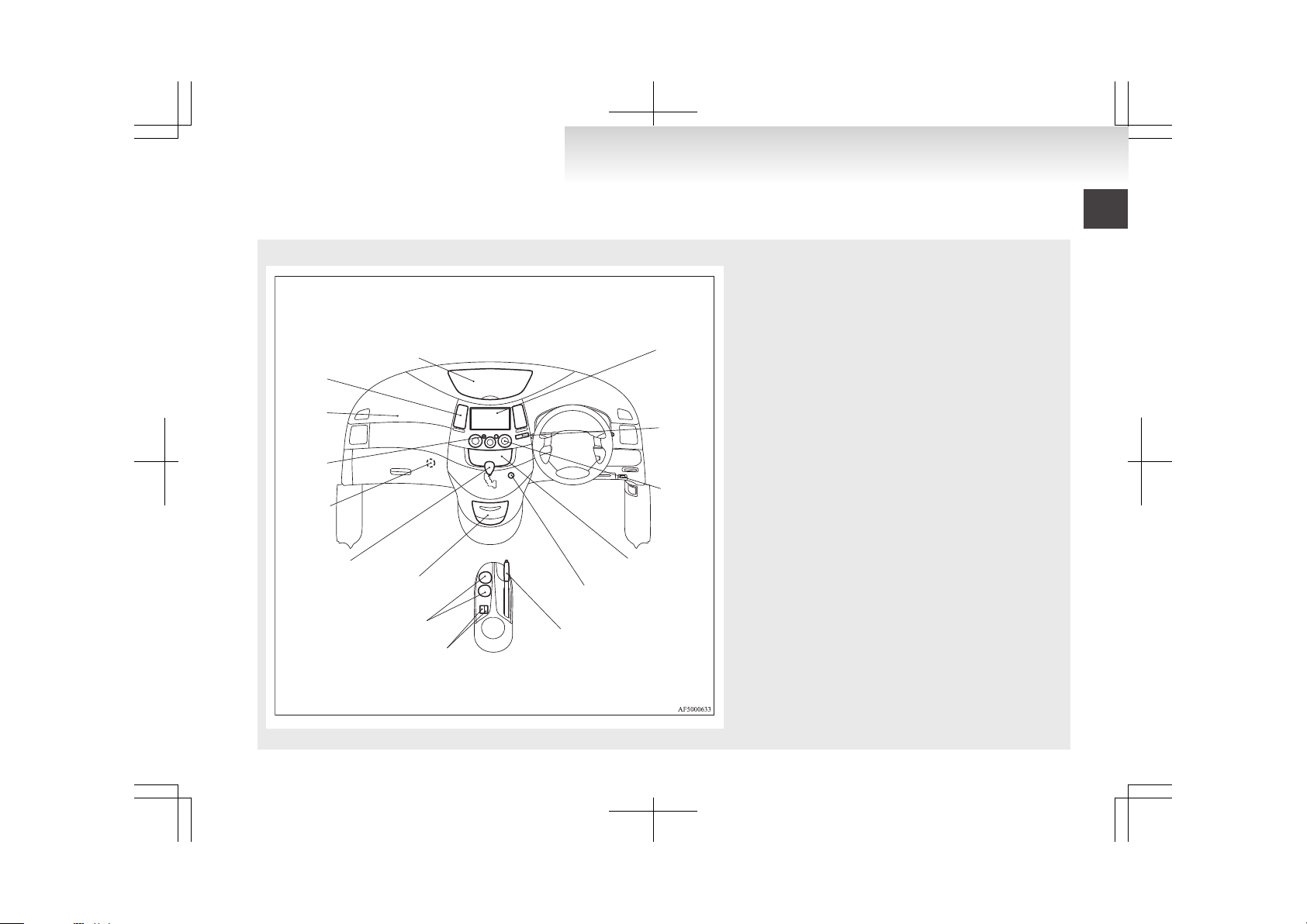
RHD
1
2
3
4
5
6
7
8
9
10
11
12
13
14
15
1. Instrument panel upper box p. 5-39
2. Multi centre display* p. 3-09
Multi display station*
Refer to the separate “Multi display station owner’s manual”
3. Front passenger’s airbag OFF indication lamp p. 2-34
4. Front automatic air conditioning p. 5-05
5. Audio p. 5-13
6. Hazard warning flasher switch p. 3-21
7. Parking brake lever p. 4-04
8. Heated seat switch* p. 2-06
9. Cup holder (for front seats) p. 5-40
10. Ashtray (fixed position) p. 5-33
11. Gearshift or selector lever p. 4-13, 4-15
12. Front passenger’s airbag ON-OFF switch p. 2-33
13. Rear window demister switch p. 3-25
14. Supplemental restraint system - airbag (for front passenger’s
seat) p. 2-29
15. Ventilators p. 5-02
Overview
Page 7
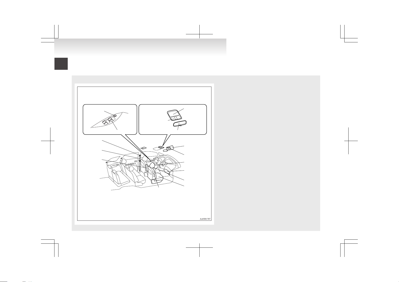
Interior (Front area)
E00100203539
LHD
1
2
3
4
5
6
7
8
9
10
11
12
13
14
15
1. Lock switch p. 1-12, 1-13
2. Electric window control switch p. 1-11
3. Room lamp & map lamps p. 5-35, 8-26, 8-30
4. Sunglasses pocket* p. 5-39
5. Inside rear-view mirror p. 4-06
6. Sun visors p. 5-32
7. Vanity mirror p. 5-32
8. Bottle holder (for front seats) p. 5-41
9. Glove box p. 5-38
10. Head restraints p. 2-11
11. Front seats p. 2-05
12. Supplemental restraint system - side airbag (for front
seats) p. 2-38
13. Armrest (for front seats)* p. 2-06
14. Seat belts p. 2-17
15. Adjustable seat belt anchor (front seats) p. 2-19
Overview
Page 8
1
2
3
4
5
6
7
8
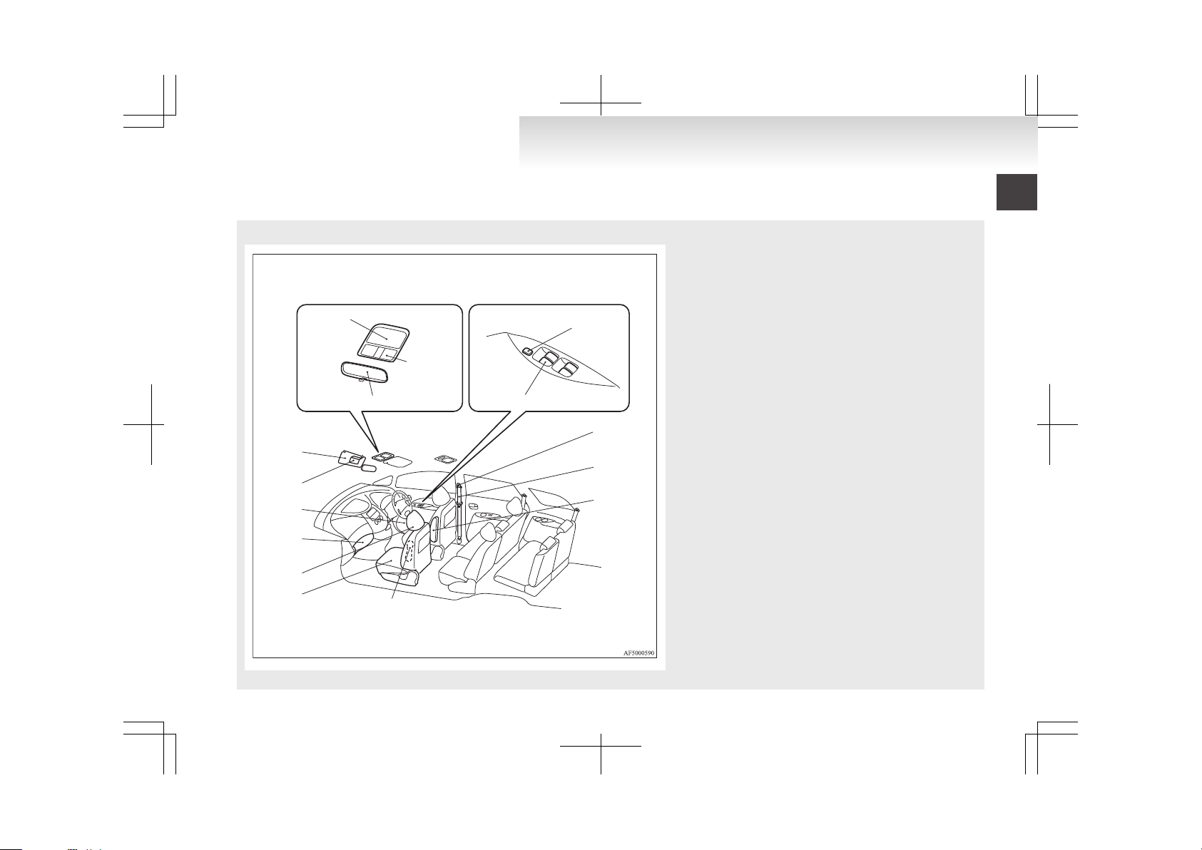
RHD
9
10
11
12
13
14
15
1. Sunglasses pocket* p. 5-39
2. Room lamp & map lamps p. 5-35, 8-26, 8-30
3. Inside rear-view mirror p. 4-06
4. Lock switch p. 1-12, 1-13
5. Electric window control switch p. 1-11
6. Adjustable seat belt anchor (front seats) p. 2-19
7. Seat belts p. 2-17
8. Armrest (for front seats) p. 2-06
9. Supplemental restraint system - side airbag (for front
seats) p. 2-38
10. Front seats p. 2-05
11. Head restraints p. 2-11
12. Glove box p. 5-38
13. Bottle holder (for front seats) p. 5-41
14. Vanity mirror p. 5-32
15. Sun visors p. 5-32
Overview
Page 9
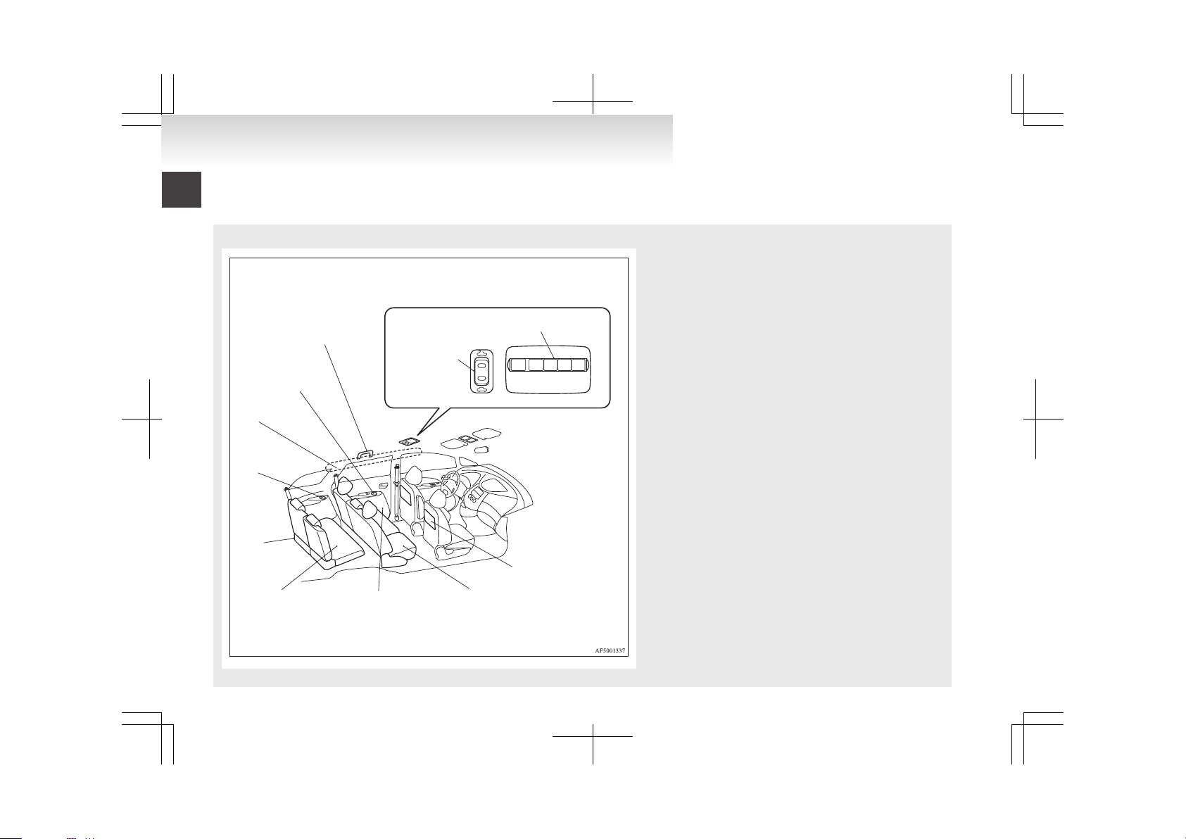
Interior (Rear area)
E00100203542
LHD
1
2
3
4
6
7
8
9
10
5
1. Sunroof switch* p. 1-13
2. Rear heater*/Rear cooler* p. 5-09
Rear automatic air conditioning* p. 5-09
3. Personal table (front seats only)* p. 5-42
4. Second seats p. 2-07
5. Bottle holder (for second seats) p. 5-41
6. Third seats* p. 2-10
7. Bottle holder (for third seats) p. 5-41
8. Supplemental restraint system - curtain airbag p. 2-39
9. Cup holder (for second seats) p. 5-40
10. Assist grip p. 5-44
Coat hooks p. 5-44
Overview
Page 10

RHD
1
2
3
4
5
6
7
8
9
10
1. Assist grip p. 5-44
Coat hooks p. 5-44
2. Cup holder (for second seats) p. 5-40
3. Supplemental restraint system - curtain airbag p. 2-39
4. Bottle holder (for third seats) p. 5-41
5. Third seats p. 2-10
6. Bottle holder (for second seats) p. 5-41
7. Second seats p. 2-07
8. Personal table (front seats only) p. 5-42
9. Sunroof switch* p. 1-13
10. Rear heater*/Rear cooler* p. 5-09
Rear automatic air conditioning* p. 5-09
Overview
Page 11

Luggage area
E00100400833
1
2
3
4
5
6
1. Luggage floor box p. 5-39
2. Warning triangle retaining bands p. 5-45
3. Spare wheel p. 6-08
4. Tools and jack p. 6-06
5. Luggage hooks p. 5-45
6. Rear side box p. 5-39
Overview
Page 12
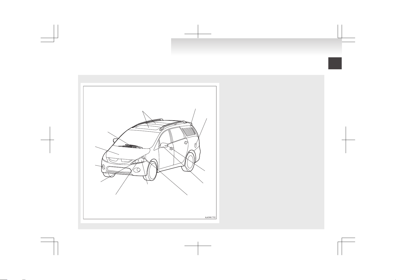
Exterior
E00100503558
1
2
3
4
5
6
8
7
9
10
11
12
1. Sunroof* p. 1-13
2. Antenna p. 5-31
3. Fuel tank filler p. 03
4. Side turn-signal lamps p. 3-21, 8-25
5. Outside rear-view mirrors p. 4-07
6. Position lamps p. 3-18, 8-25, 8-28
7. Headlamps, low beam p. 3-18, 8-25, 8-26
8. Headlamps, high-beam p. 3-18, 8-25, 8-26
9. Front turn-signal lamps p. 3-21, 8-25, 8-28
10. Front fog lamps p. 3-22, 8-25, 8-28
11. Bonnet p. 8-03
12. Windscreen wipers p. 3-23
Overview
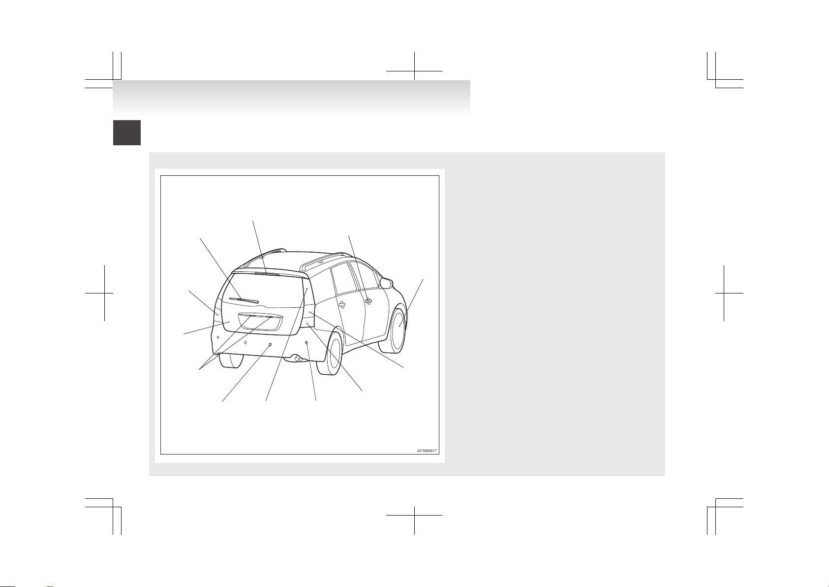
Page 13
1
2
3
4
5
6
7
8
9
10
11
12
1. High-mounted stop lamp p. 8-25
2. Locking and unlocking p. 1-06
Keyless entry system* p. 1-04
3. Tyre inflation pressures p. 8-12
Changing tyres p. 6-11
Tyre rotation p. 8-13
Tyre chains p. 8-14
Wheel covers* p. 6-13
4. Rear turn-signal lamps p. 3-21, 8-25, 8-29
5. Reversing lamp (LHD vehicles) p. 8-25, 8-29
Rear fog lamp (RHD vehicles) p. 3-22, 8-25, 8-29
6. Corner sensors* p. 4-29
7. Stop and tail lamps p. 3-18
8. Back sensors* p. 4-29
9. Licence plate lamps p. 3-18, 8-25, 8-30
10. Tailgate p. 1-08
11. Rear fog lamp (LHD vehicles) p. 3-22, 8-25, 8-29
Reversing lamp (RHD vehicles) p. 8-25, 8-29
12. Rear window wiper and washer p. 3-24
Overview
Page 14

Fuel selection...................................................................................02
Filling the fuel tank..........................................................................03
Installation of accessories................................................................04
Modification/alterations to the electrical or fuel systems................05
Genuine parts...................................................................................05
Used engine oils safety instructions and disposal infor-
mation..........................................................................................06
Disposal information for used batteries...........................................06
General information
Page 15

Fuel selection
E00200102343
Recommen-
ded fuel
Petrol-powered vehicles
Unleaded petrol octane number (EN228)
95 RON or higher
Diesel-powered vehicles
Cetane number (EN590)
51 or higher
CAUTION
l
For petrol-powered vehicles, the use of leaded fuel can result in serious damage to
the engine and catalytic converter. Do not
use leaded fuel.
l
Diesel-powered vehicles are designed to
use only diesel fuel that meets the EN 590
standard.
Use of any other type of diesel fuel would
adversely affect the engine’s performance
and durability.
NOTE
l
Due to the separation of paraffin, the fluidity
of the fuel decreases considerably as the temperature falls.
Because of this fact there are two kinds of
fuel: “summer” and “winter”.
This must be considered in winter use.
Select either of the two kinds of fuel in accordance with ambient temperature.
Above -5 °C: “Summer” diesel
Below -5 °C: “Winter” diesel
When travelling abroad, find out in advance
about the fuels served in local service stations.
l
Petrol-powered vehicles have the knock control system so that you can use unleaded petrol 90 RON as an emergency measure in
case unleaded petrol 95 RON or higher is not
available on journey, etc. In such a case, you
don’t need to adjust the engine specially.
In case of using unleaded petrol 90 RON, the
engine performance level is reduced.
l
Repeatedly driving short distance at low
speeds can cause deposits to form in the fuel
system and engine, resulting in poor starting
and poor acceleration. If these problems occur, you are advised to add a detergent additive to the petrol when you refuel the vehicle.
The additive will remove the deposits, thereby returning the engine to a normal condition. Be sure to use a genuine
MITSUBISHI FUEL SYSTEM CLEANER.
Using an unsuitable additive could make the
engine malfunction. For details, please contact your MITSUBISHI MOTORS Authorized Service Point.
l
Poor quality petrol can cause problems such
as difficult starting, stalling, engine noise
and hesitation. If you experience these problems, try another brand and/or grade of petrol.
If the check engine warning lamp flashes,
have the system checked as soon as possible
at a MITSUBISHI MOTORS Authorized
Service Point.
General information
02
Page 16

Filling the fuel tank
E00200202142
WARNING
l
Petrol is highly flammable and explosive.
You could be burned or seriously injured
when handling it. When refueling your vehicle, always turn the engine off and keep
away from flames, sparks, and smoking
materials. Always handle fuel in well-ventilated outdoor areas.
l
Before removing the fuel cap, be sure to
get rid of your body’s static electricity by
touching a metal part of the car or the
fuel pump. Any static electricity on your
body could create a spark that ignites
fuel vapour.
l
Perform the whole refueling process
(opening the fuel tank filler door, removing the fuel cap, etc.) by yourself. Do not
let any other person come near the fuel
tank filler. If you allowed a person to
help you and that person was carrying
static electricity, fuel vapour could be ignited.
l
Do not move away from the fuel tank filler until refueling is finished. If you
moved away and did something else (for
example, cleaning your windscreen) partway through the refueling process, you
could pick up a fresh charge of static electricity.
l
Be careful not to inhale fuel vapour. Fuel
contains toxic substances.
WARNING
l
Keep the doors and windows closed while
refueling the vehicle. If they were open,
fuel vapour could get into the cabin.
Fuel tank capacity
65 litres
Refueling
1. Before filling with fuel, stop the engine.
2. The fuel tank filler is located on the rear left
side of your vehicle.
The fuel tank filler door can be opened from
inside the vehicle with the fuel tank filler
door release lever located below the instrument panel.
LHD
RHD
3. Open the fuel tank filler tube by slowly turning the cap anticlockwise.
A- Remove
B- Close
General information
03
Page 17
CAUTION
l
Since the fuel system may be under pressure, remove the fuel tank filler tube cap
slowly. This relieves any pressure or vacuum that might have built up in the fuel
tank. If you hear a hissing sound, wait until it stops before removing the cap. Otherwise, fuel may spray out, injuring you
or others.
4. To fill with fuel correctly depends mainly on
correct handling of the fuel filler gun. Do not
tilt the gun. Insert the gun in the tank port as
far as it goes.
CAUTION
l
A label which reads “UNLEADED FUEL
ONLY” is attached to the fuel tank filler
lid of vehicles which can only operate using unleaded petrol. Serious engine and
catalytic converter damage will result if
leaded petrol is filled into these vehicles,
and consequently, this must never be attempted.
5. When the gun stops automatically, do not fill
with fuel any more.
CAUTION
l
To avoid fuel spillage and overfilling, do
not “top-off” the fuel tank.
6. To close, turn the fuel tank filler tube cap
slowly clockwise until you hear clicking
sounds, then gently push the fuel tank filler
door closed.
CAUTION
l
If you need to replace the fuel tank filler
tube cap, use only the cap specified for
your model vehicle.
Installation of accessories
E00200300745
We recommend you to consult your MITSUBISHI
MOTORS Authorized Service Point.
l
The installation of accessories, optional
parts, etc., should only be carried out within
the limits prescribed by law in your country,
and in accordance with the guidelines fitting
instructions and warnings contained within
the documents accompanying the parts or accessories.
l
Improper installation of electrical components may cause an electrical fire if incorrectly fitted. Please refer to the Modification/alteration to the electrical or fuel systems section within this owner’s manual.
l
Using a cellular phone or radio set inside the
vehicle without an external antenna may
cause electrical system interference, which
could lead to unsafe vehicle operation.
l
Tyres and wheels which do not meet specifications must not be used.
Refer to the “Specifications” section for information regarding wheel and tyre sizes.
Important points!
Due to the large number of accessory and replacement parts of different manufactures available in
the market, it is not possible, not only for
MITSUBISHI MOTORS, but also a MITSUBISHI
MOTORS Authorized Service Point, to check
whether the attachment or installation of such parts
affects thedriving safety of your MITSUBISHI-vehicle.
General information
04
Page 18

Even when such parts are officially authorized, for
example by a “general operators permit” (an appraisal for the part) or through the execution of the
part in an officially approved manner of construction, or when a single operation permit following
the attachment or installation of such parts, it cannot be deduced from that alone, that the driving safety of your vehicle has not been affected.
Consider also that there basically exists no liability
on the part of the appraiser or the official. Only in
the case of parts (MITSUBISHI MOTORS original
replacement or exchange parts as well as
MITSUBISHI MOTORS genuine accessories) that
are recommended and released by a MITSUBISHI
MOTORS Authorized Service Point and that are attached or installed by a MITSUBISHI MOTORS
Authorized Service Point can you assume, that optimal safety has been provided. The same also pertains to modifications of MITSUBISHI vehicles
with respect to the production specifications. For
your own safety, in such cases as well, you should
only undertake modifications according to the recommendations of a MITSUBISHI MOTORS Authorized Service Point.
Modification/alterations to the
electrical or fuel systems
E00200400238
MITSUBISHI MOTORS has always manufactured
safe, high quality vehicles. In order to maintain this
safety and quality, it is important that any accessory that is to be fitted, or any modifications carried
out which involve the electrical or fuel systems,
should be carried out in accordance with
MITSUBISHI MOTORS guidelines.
CAUTION
l
If the wiring interferes with any part of
the vehicle bodywork or improper installation methods are used, i.e. protective
fuses not installed, etc.), electronic devices may be adversely affected, possibly resulting in an electrical fire or other failures that may cause an accident.
Genuine parts
E00200500590
MITSUBISHI MOTORS has gone to great lengths
to bring you a superbly crafted automobile offering
the highest quality and dependability.
Use MITSUBISHI MOTORS genuine parts, designed and manufactured to maintain your
MITSUBISHI MOTORS automobile at top performance. MITSUBISHI MOTORS genuine parts
are identified by this mark and are available at all
MITSUBISHI MOTORS Authorized Service
Points.
General information
05
Page 19
Used engine oils safety
instructions and disposal
information
E00200600025
WARNING
l
Prolonged and repeated contact may
cause serious skin disorders, including
dermatitis and cancer.
l
Avoid contact with the skin as far as possible and wash thoroughly after any contact.
l
Keep used engine oils out of reach of children.
Protect the environment
It is illegal to pollute drains, water courses and soil.
Use authorized waste collection facilities, including civic amenity sites and garages providing facilities for disposal of used oil and used oil filters. If in
doubt, contact your local authority for advice on disposal.
Disposal information for used
batteries
E00201300016
Your vehicle contains batteries
and/or accumulators.
Do not mix with general household waste.
For proper treatment, recovery
and recycling of used batteries,
please take them to applicable collection points, in accordance
with your national legislation
and the Directives 2006/66/EC.
By disposing of these batteries
correctly, you will help to save
valuable resources and prevent
any potential negative effects on
human health and the environment which could otherwise
arise from inappropriate waste
handling.
General information
06
Page 20
Keys..............................................................................................1-02
Electronic immobilizer (Anti-theft starting system).....................1-03
Keyless entry system*..................................................................1-04
Doors............................................................................................1-06
Central door locks.........................................................................1-07
Child-protection rear doors...........................................................1-08
Tailgate.........................................................................................1-08
Inside tailgate release....................................................................1-10
Electric window control................................................................1-11
Sunroof*.......................................................................................1-13
Locking and unlocking
1
Page 21
Keys
E00300102096
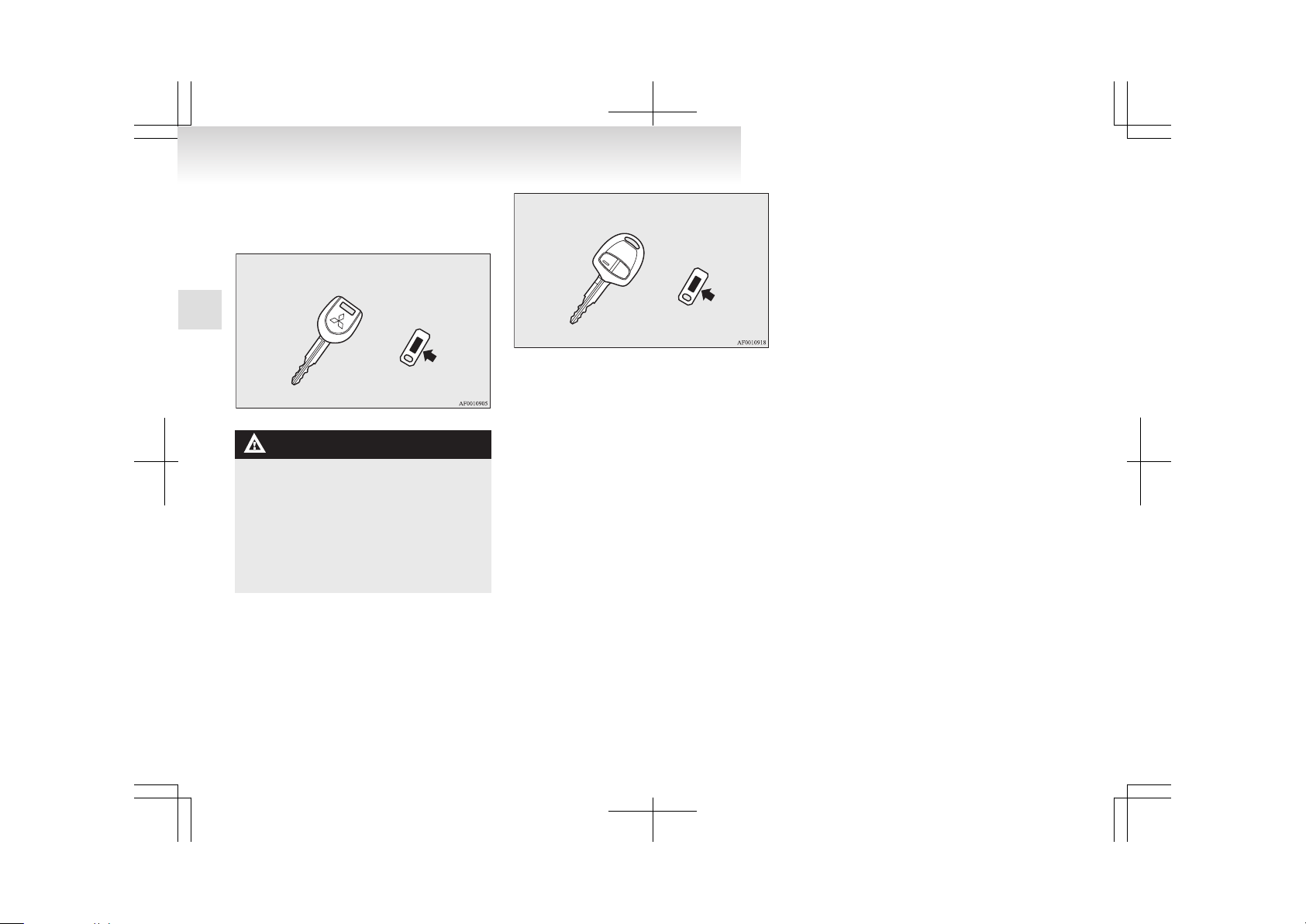
The key fits all locks.
Type 1
WARNING
l
When taking a key on flights, do not
press any switches on the key while on
the plane. If a switch is pressed on the
plane, the key emits electromagnetic
waves, which could adversely affect the
plane’s flight operation.
When carrying a key in a bag, be careful
that no switches on the key can be easily
pressed by mistake.
Type 2
NOTE
l
The key number is stamped on the tag as indicated in the illustration.
Make a record of the key number and store
the key and key number tag in separate places, so that you can order a key in the event
the original keys are lost.
l
The key is a precision electronic device with
a built-in signal transmitter. Please observe
the following in order to prevent a malfunction.
• Do not leave in a place that is exposed to
direct sunlight, for example on the dashboard.
• Do not disassemble or modify.
• Do not excessively bend the key or subject it to strong impacts.
• Do not expose to water.
• Keep away from magnetic key rings.
• Keep away from audio systems, personal
computers, TVs, and other equipment
that generates a magnetic field.
• Do not clean with ultrasonic cleaners or
similar equipment.
• Do not leave the key where it may be exposed to high temperature or high humidity.
l
The engine is designed so that it will not
start if the ID code registered in the immobilizer computer and the key’s ID code do not
match. Refer to the “Electronic immobilizer”
section for details and key usage.
Keys should never be placed in areas which
contain magnetic or metal objects as this
may interfere with the transponder.
Locking and unlocking
1-02
1
Page 22
Electronic immobilizer
(Anti-theft starting system)
E00300201553
The electronic immobilizer is designed to significantly reduce the possibility of vehicle theft. The
purpose of the system is to immobilize the vehicle
if an invalid start is attempted. A valid start attempt
can only be achieved (subject to certain conditions)
using a keyless operation system “registered” to
the immobilizer system.
NOTE
l
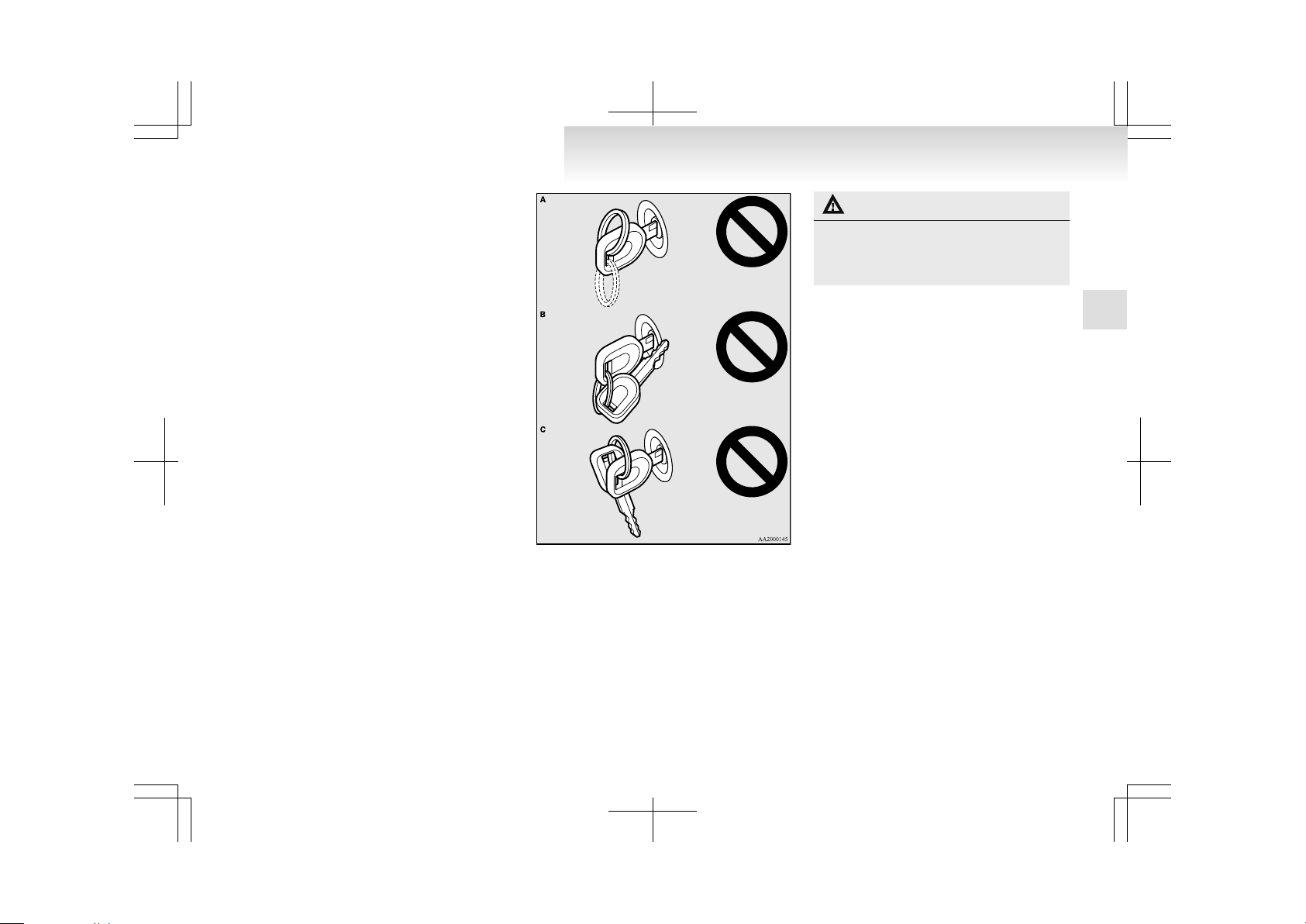
In the following cases, the vehicle may not
be able to receive the registered ID code
from the key. This means the engine will not
start even when the registered key is turned
to the “START” position.
• When the key contacts a key ring or other
metallic or magnetic object (Type A)
• When the key grip contacts metal of another key (Type B)
• When the key contacts or is close to other
immobilizing keys (including keys of other vehicles) (Type C)
In cases like these, remove the object or
additional key from the vehicle key and
turn the key back to the “ACC” or
“LOCK” position. Then try again to start
the engine. If the engine does not start,
we recommend you to contact your
MITSUBISHI MOTORS Authorized
Service Point.
NOTE
l
If you lose your key, order a key from your
MITSUBISHI MOTORS Authorized Service
Point as soon as possible.
To obtain a replacement or extra spare key,
take your vehicle and all remaining keys to
your MITSUBISHI MOTORS Authorized
Service Point. All the keys have to be re-registered in the immobilizer computer unit.
The immobilizer can register up to 8 different keys.
CAUTION
l
Don’t make any alterations or additions
to the immobilizer system; alterations or
additions could cause failure of the immobilizer.
Locking and unlocking
1-03
1
Page 23
Keyless entry system*
E00300302115
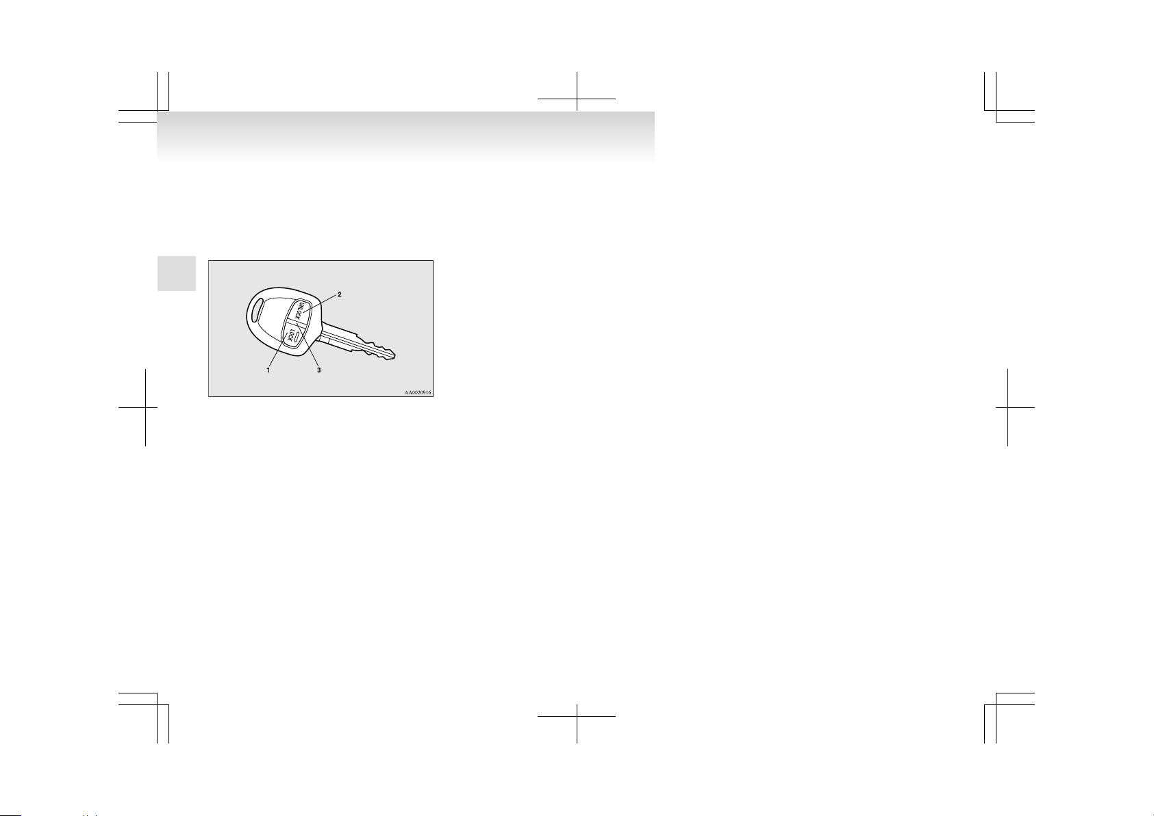
Press the remote control switch, and all doors and
the tailgate will be locked or unlocked as desired. It
is also possible to operate the outside rear-view mirrors.
1- LOCK switch
2- UNLOCK switch
3- Indication lamp
To lock
Press the LOCK switch (1). All the doors and the
tailgate will be locked. If the interior lamp switch
is in the middle position (DOOR) at this time, the
room lamp & map lamps, the rear personal lamps,
and the turn-signal lamps will blink once.
To unlock
Press the UNLOCK switch (2). All the doors and
the tailgate will be unlocked. If the interior lamp
switch is in the middle position (DOOR) at this
time, the room lamp & map lamps and the rear personal lamps will come on for approximately 15 seconds and the turn-signal lamps will blink twice.
NOTE
l
The indication lamp (3) comes on each time
a switch is pressed.
l
If the UNLOCK switch (2) is pressed and no
door or tailgate is opened within approximately 30 seconds: relocking will automatically
occur.
l
It is possible to modify functions as follows:
For further information, please contact your
MITSUBISHI MOTORS Authorized Service
Point.
On a vehicle equipped with a Multi Display
Station (MDS), the functions can be adjusted
on the screen. Refer to the separate operation
manual for details.
• The time from pressing the UNLOCK
switch (2) to the moment of automatic
locking can be changed.
• The confirmation function (flashing of
the turn-signal lamps) can be set to operate only when the doors and backdoor are
locked or only when the doors and backdoor are unlocked.
• The confirmation function (this indicates
locking or unlocking of the doors and tailgate with the flash of the turn-signal
lamps) can be deactivated.
• The number of times the turn-signal
lamps are flashed by the confirmation
function can be changed.
Operation of the outside rear-view mirrors
To fold
Within 30 seconds of locking the doors and tailgate
using the LOCK switch (1), press the LOCK
switch twice rapidly to fold the outside rear-view
mirrors.
To extend
Within 30 seconds of unlocking the doors and tailgate using the UNLOCK switch (2), press the UNLOCK switch twice rapidly to return the outside
rear-view mirrors to their extended positions.
NOTE
l
The keyless entry system does not operate in
the following conditions:
• The key is left in the key cylinder.
• The door or tailgate is open.
l
The remote control switch will operate within about 4 m from the vehicle. However, the
operating range of the remote control switch
may change if the vehicle is located near a
power station, or radio/TV broadcasting station.
l
If either of the following problems occurs,
the battery may be exhausted.
• The remote control switch is operated at
the correct distance from the vehicle, but
the doors and tailgate are not locked/unlocked in response.
• The indication lamp (3) is dim or does
not come on.
For further information, please contact
your MITSUBISHI MOTORS Authorized Service Point.
If you replace the battery yourself, refer
to “Procedure for replacing the remote
control switch battery” on page 1-05.
l
If your remote control switch is lost or damaged, please contact your MITSUBISHI
MOTORS Authorized Service Point for a replacement remote control switch.
Locking and unlocking
1-04
1
Page 24
l
If you wish to add a remote control switch,
we recommend you to contact your
MITSUBISHI MOTORS Authorized Service
Point.
A maximum of 4 remote control switches are
available for your vehicle.
Procedure for replacing the remote control switch battery
E00309500086
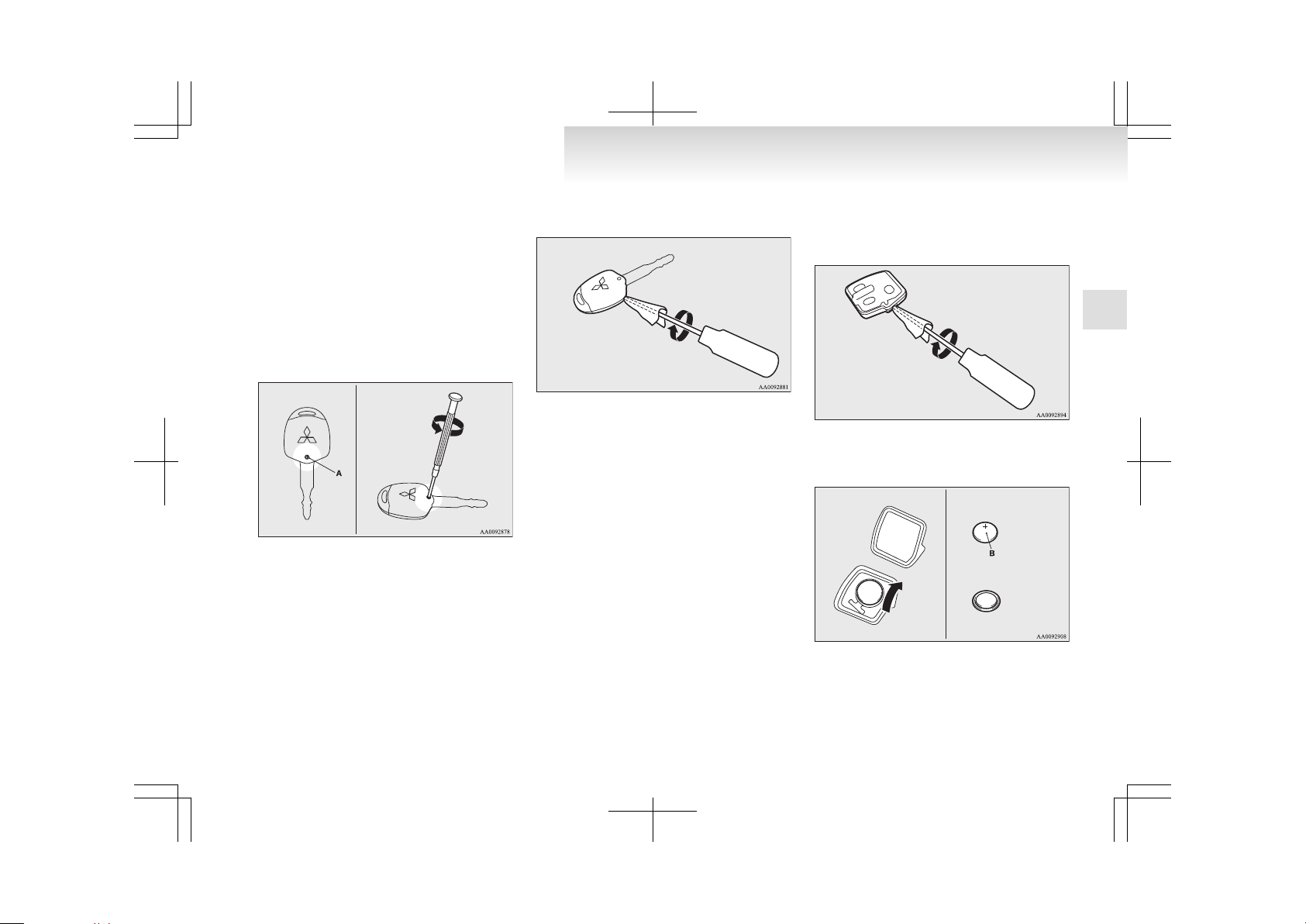
1. Remove the screw (A) from the remote control switch.
2.
With the MITSUBISHI mark facing you, insert the cloth covered tip of a straight blade
(or minus) screwdriver into the notch in the
remote control switch case and use it to open
the case.
NOTE
l
Be sure to perform the procedure with the
MITSUBISHI mark facing you. If the
MITSUBISHI mark is not facing you when
you open the remote control switch case, the
switches may come out.
3. Remove the remote control transmitter from
the remote control switch case. Then, open
the remote control transmitter using the method described in step 2.
4. Remove the old battery.
5. Install a new battery with the + side (B) down.
Coin type battery
CR1616
- side
+ side
6. Close the remote control transmitter firmly.
7. Place the remote control transmitter in the remote control switch case, then securely close
the remote control switch case.
8. Attach the screw (A) removed in step 1.
Locking and unlocking
1-05
1
Page 25
9. Check the keyless entry system to see that it
works.
NOTE
l
You may purchase a replacement battery at
an electric appliance store.
l
A MITSUBISHI MOTORS Authorized Service Point can replace the battery for you if
you prefer.
CAUTION
l
When the remote control switch case is
opened, be careful to keep water, dust,
etc. out. Also, do not touch the internal
components.
Doors
E00300401845
CAUTION
l
Make sure the doors are closed: driving
with doors not completely closed is dangerous.
l
Never leave children in the vehicle unattended.
l
Be careful not to lock the doors while the
key is inside the vehicle.
NOTE
l
To prevent the key from being locked inside
the vehicle, neither the lock knob on the driver’s door nor the key can be used to lock the
driver’s door when it is open.
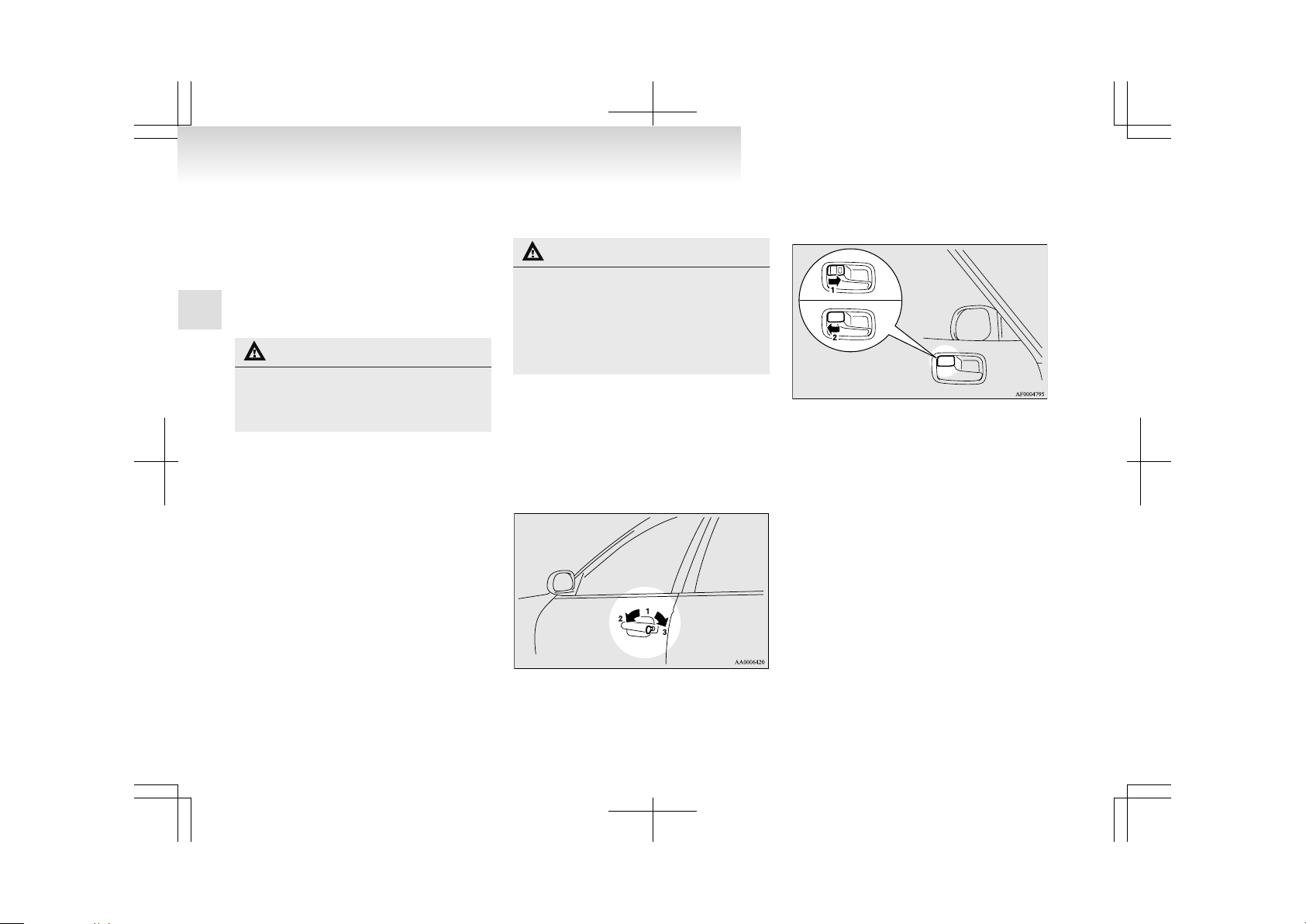
To lock or unlock with the key
1- Insert or remove the key
2- Lock
3- Unlock
To lock or unlock from inside the vehicle
1- Lock
2- Unlock
Pull the inside door handle towards you to open the
door.
NOTE
l
The driver’s door can be opened without using the lock knob by pulling on the inside
door handle.
All other doors and the tailgate are unlocked
at the same time.
Locking and unlocking
1-06
1
Page 26

To lock without using the key
Front passenger’s door, Rear door
Set the inside lock knob (1) to the locked position,
and close the door (2).
NOTE
l
The driver’s door cannot be locked using the
inside lock knob while the driver’s door is
opened.
Central door locks
E00300800897
NOTE
l
Each of the doors can be locked or unlocked
independently by using the inside lock knob.
l
Repeated continuous operation between lock
and unlock could activate the central door
locking systems built-in protection circuit
and prevent the system from operating. If
this occurs, wait about one minute before operating the inside lock knob or the key.
l
When the driver’s door is open, neither the
key nor the lock knob can be used to lock it.
All of the doors and the tailgate can be locked and
unlocked as described hereafter.
Driver’s door with key
Turn the key in the driver’s door towards the front
of the vehicle to lock the doors and the tailgate and
towards the rear of the vehicle to unlock the doors
and the tailgate.
1- Lock
2- Unlock
Driver’s door with inside lock knob
Set the inside lock knob on the driver’s door towards the front of the vehicle to lock the doors and
the tailgate. Set it towards the rear of the vehicle to
unlock the doors and the tailgate.
1- Lock
2- Unlock
Locking and unlocking
1-07
1
Page 27
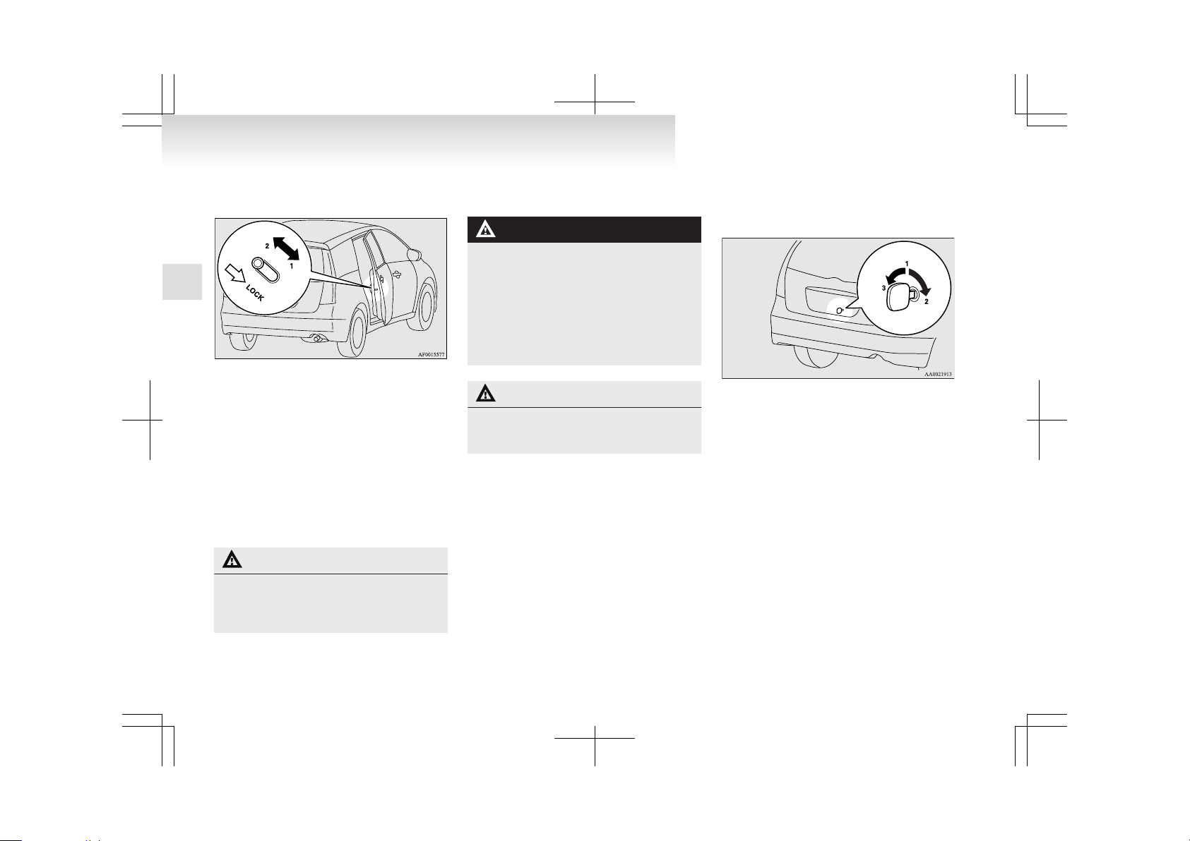
Child-protection rear doors
E00300900915
1- Lock
2- Unlock
Child protection helps prevent doors from being
opened accidentally, especially when small children are in the rear seat.
A lever is provided on each rear door.
If the lever is set to the locked position, the rear
door cannot be opened using the inside handle.
To open the rear door while the child protection is
in use, pull the outside door handle.
If the lever is set to the “Unlock” position, the
child protection mechanism does not function.
CAUTION
l
When driving with a child in the rear
seat, please use the child protection to prevent accidental door opening which may
cause an accident.
Tailgate
E00301400933
WARNING
l
It is dangerous to drive with the tailgate
open, since carbon monoxide (CO) gas
can enter the cabin.
You cannot see or smell CO. It can cause
unconsciousness and even death.
l
When opening and closing the tailgate,
make sure that there are no people nearby and be careful not to hit your head or
pinch your hands, neck, etc.
CAUTION
l
Do not stand behind the exhaust pipe
when loading and unloading luggage.
Heat from the exhaust could lead to burns.
NOTE
l
Locking/unlocking of the driver’s door by using the key, inside lock knob (driver side) or
keyless entry system (if so equipped) also
locks/unlocks the tailgate.
To lock or unlock from outside the vehicle (Except for vehicles with keyless
entry system)
1- Insert (or remove) the key
2- Lock
3- Unlock
Locking and unlocking
1-08
1
Page 28

To lock or unlock from inside the vehicle
The tailgate can be locked or unlocked by using the
inside lock knob (driver side), regardless of the position of the ignition key.
1- Lock
2- Unlock
If the tailgate is locked or unlocked by using the inside lock knob (driver side), it can still be locked or
unlocked with the key.
NOTE
l
Repeated continuous operating between lock
and unlock could cause the central door
lock’s built-in protection circuit to prevent
the system from operating. If this occurs,
wait about 1 minute before operating the inside lock knob.
To open
Pull the tailgate handle upward to open the tailgate.
CAUTION
l
Make sure there is no one standing nearby when opening the tailgate.
NOTE
l
If you do not open the tailgate immediately
after pulling the handle, the tailgate will automatically be relocked. If this happens, pull
the handle again and lift the tailgate with the
handle still pulled.
l
The tailgate cannot be opened when the battery is flat or disconnected.
To close
Pull the tailgate grip (A) downward as illustrated
and release it before the tailgate closes completely.
Gently shut the tailgate from the outside so that it
is completely closed.
CAUTION
l
To avoid injuring your hand or arm, do
not attempt to close the tailgate without
letting go off the tailgate grip.
l
Before driving, make sure that the tailgate is securely closed.
If the tailgate opens while driving the vehicle, objects stored in the luggage area
could fall out onto the road.
NOTE
l
Gas struts (B) are installed in the locations illustrated to support the tailgate. Please observe the following in order to prevent damage or faulty operation.
Locking and unlocking
1-09
1
Page 29
• Do not hold the gas struts when closing
the tailgate. Also, do not push or pull the
gas struts.
• Do not attach any plastic material, tape,
etc., to the gas struts.
• Do not tie string, etc., around the gas struts.
• Do not hang any object on the gas struts.
Inside tailgate release
E00303400041
The inside tailgate release is designed to provide a
way to open the tailgate in the case of a discharged
battery.
The tailgate release lever (see illustration) is mounted on the tailgate.
You and your family should familiarize yourselves
with the location and operation of the tailgate release lever.
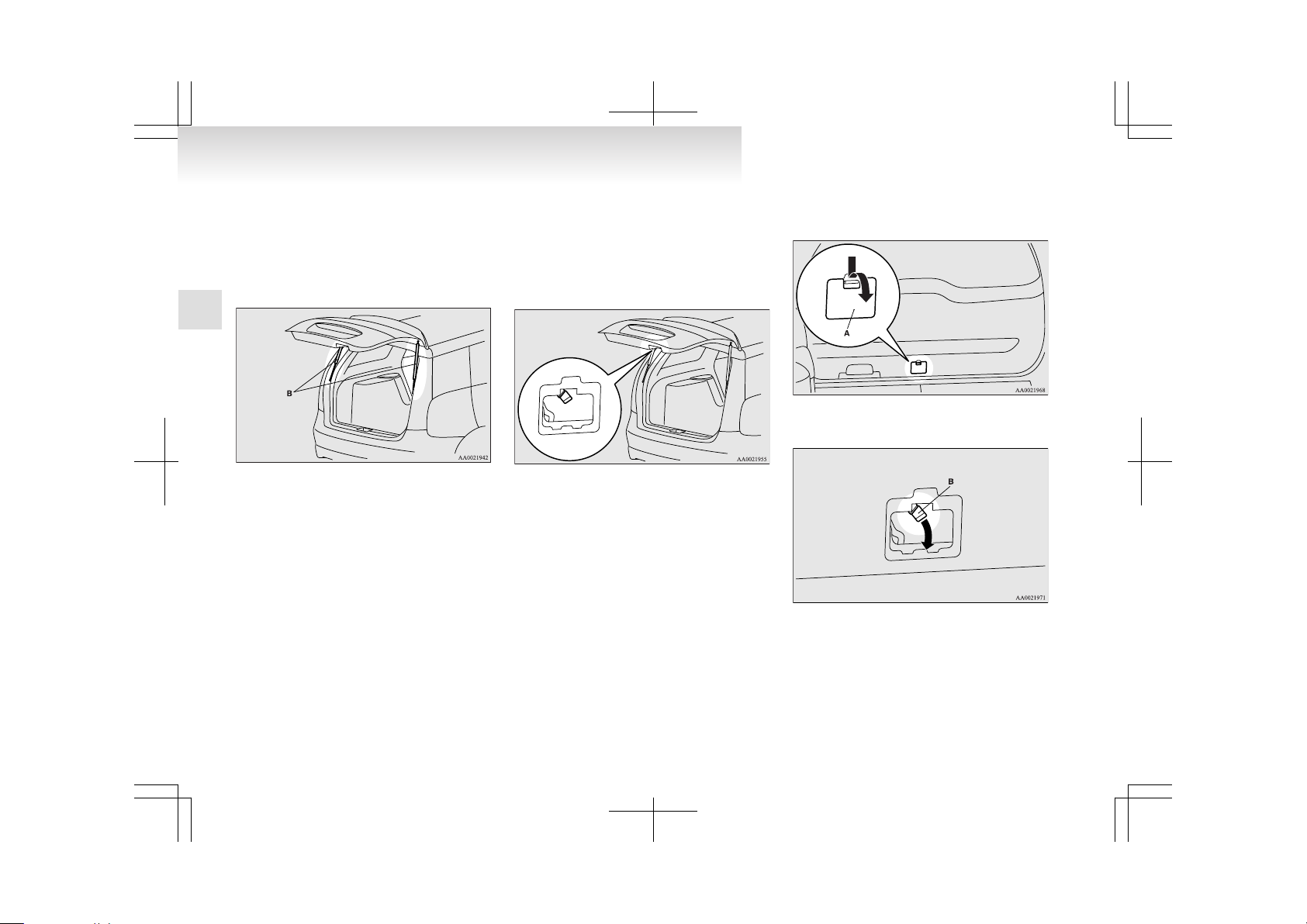
To open
1. Open the lid (A) inside of the tailgate.
2. Move the lever (B) to unlock the tailgate.
3. Push the tailgate to open the tailgate.
Locking and unlocking
1-10
1
Page 30
CAUTION
l
Always keep the release lever lid on tailgate closed when driving so that your luggage cannot accidentally bump against
the lever and open the tailgate.
Electric window control
E00302200042
The electric windows can only be operated with the
ignition switch in the “ON” position.
Electric window control switch
E00302300144
Each door window opens or closes while the corresponding switch is operated.
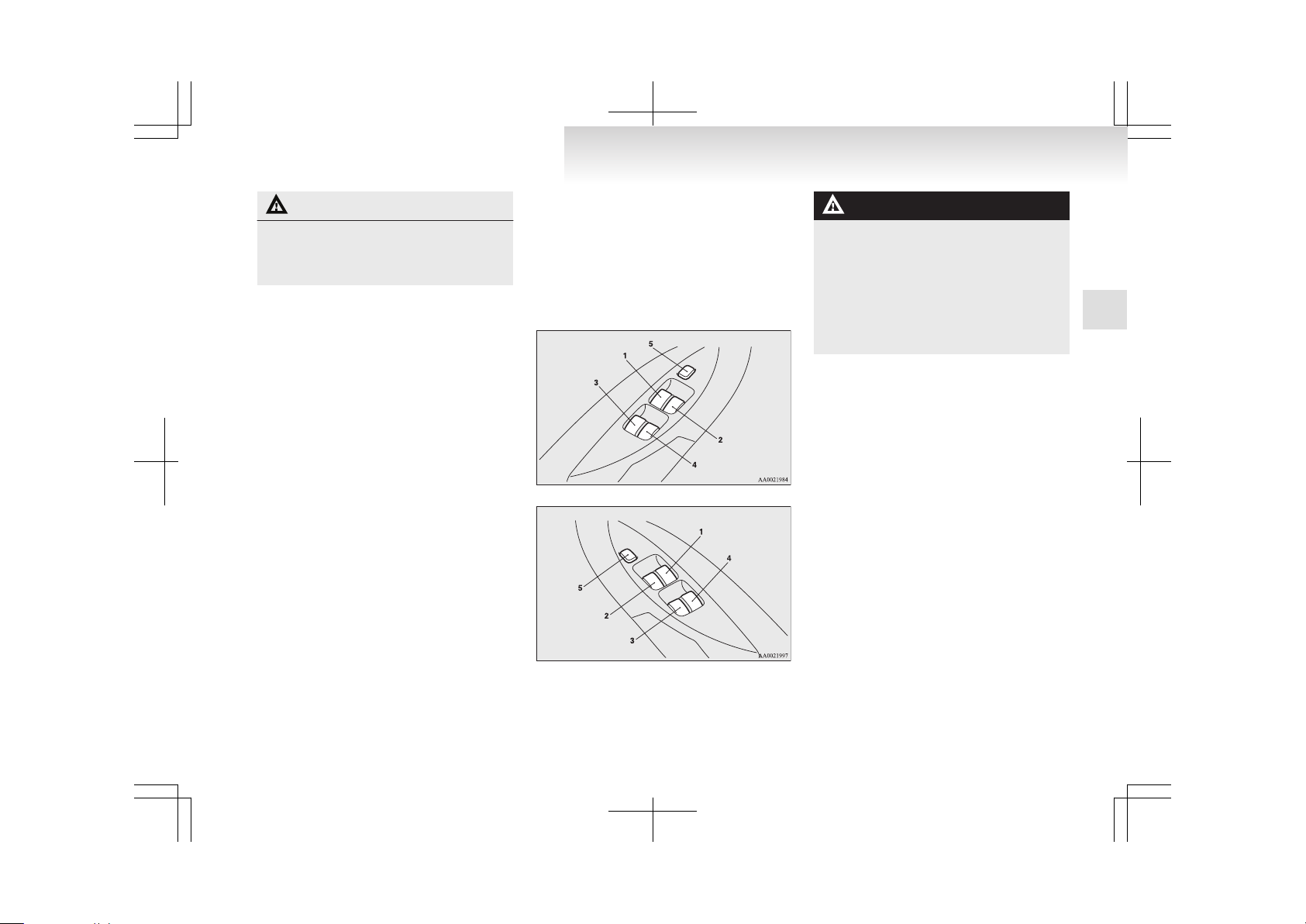
Driver’s switch (LHD)
Driver’s switch (RHD)
1- Driver’s door window
2- Front passenger’s door window
3- Rear left door window
4- Rear right door window
5- Lock switch
WARNING
l
Before operating the electric window control, make sure that nothing can get trapped (head, hand, finger, etc.).
l
Never leave the vehicle without removing
the key.
l
Never leave a child (or other person who
might not be capable of safe operation of
the electric window control) in the vehicle
alone.
NOTE
l
Repeated operation with the engine stopped
will run down the battery. Operate the window switches only while the engine is running.
Driver’s switches
The driver’s switches can be used to operate all
door windows. A window can be opened or closed
by operating the corresponding switch.
Press the switch down to open the window, and
pull up the switch to close it.
If the switch is fully pressed down/pulled up, the
door window automatically opens/closes completely.
If you want to stop the window movement, operate
the switch lightly in the reverse direction.
Passenger’s switches
The passenger’s switches can be used to operate
the corresponding passenger’s door windows.
Locking and unlocking
1-11
1
Page 31
Press the switch down for opening the window,
and pull up the switch for closing it.
Passenger’s switch
NOTE
l
The rear door windows only open halfway.
Lock switch
E00303100338
When this switch is operated, the passenger’s
switches cannot be used to open or close the door
windows.
To unlock, press it once again.
1- Lock
2- Unlock
NOTE
l
The driver’s switch can open or close any
door windows.
WARNING
l
A child may tamper with the switch at
the risk of its hands or head being trapped in the window. When driving with a
child in the vehicle, please press the window lock switch to disable the passenger’s switches.
NOTE
l
It is possible to prevent the driver’s door
switches from being used to open and close
the front passenger’s door window and rear
door windows while the lock switch is pressed in the “LOCK” position.
For details, we recommend you to consult a
MITSUBISHI MOTORS Authorized Service
Point.
Timer function
E00302400611
The door windows can be opened or closed for 30
seconds after the ignition switch is turned from the
“ON” position to the “ACC” or “LOCK” position.
If the driver’s door is opened during this period,
the door window can be opened or closed for another 30 seconds.
However, once the driver’s door is closed, the windows cannot be operated.
Safety mechanism
E00302500449
If a hand or head is trapped in the closing window,
it will lower automatically.
Nonetheless, make sure that nobody puts their head
or hand out of the window when closing a window.
The lowered window will become operational after
a few seconds.
WARNING
l
If the safety mechanism is activated three
or more times successively, the safety
mechanism will be temporarily cancelled.
If a hand or head got trapped, a serious
injury could result.
Locking and unlocking
1-12
1
Page 32
CAUTION
l
The safety mechanism is cancelled just before the window is fully closed. This allows the window to close completely.
Therefore be especially careful that no fingers are trapped in the window.
NOTE
l
The safety mechanism can be activated if the
driving conditions or other circumstances
cause the door windows to be subjected to a
physical shock similar to that caused by a trapped hand or head.
l
If the safety mechanism is activated three or
more times in a row, the safety mechanism
will be cancelled and the door window will
not close correctly.
In such a case, the following procedure
should be implemented to rectify this situation. If the window is open, repeatedly raise
the appropriate window switch until that window has been fully closed. Following this, release the switch, raise the switch once again
and hold it in this condition for at least 1 second, then release it. You should now be able
to operate all windows in the normal fashion.
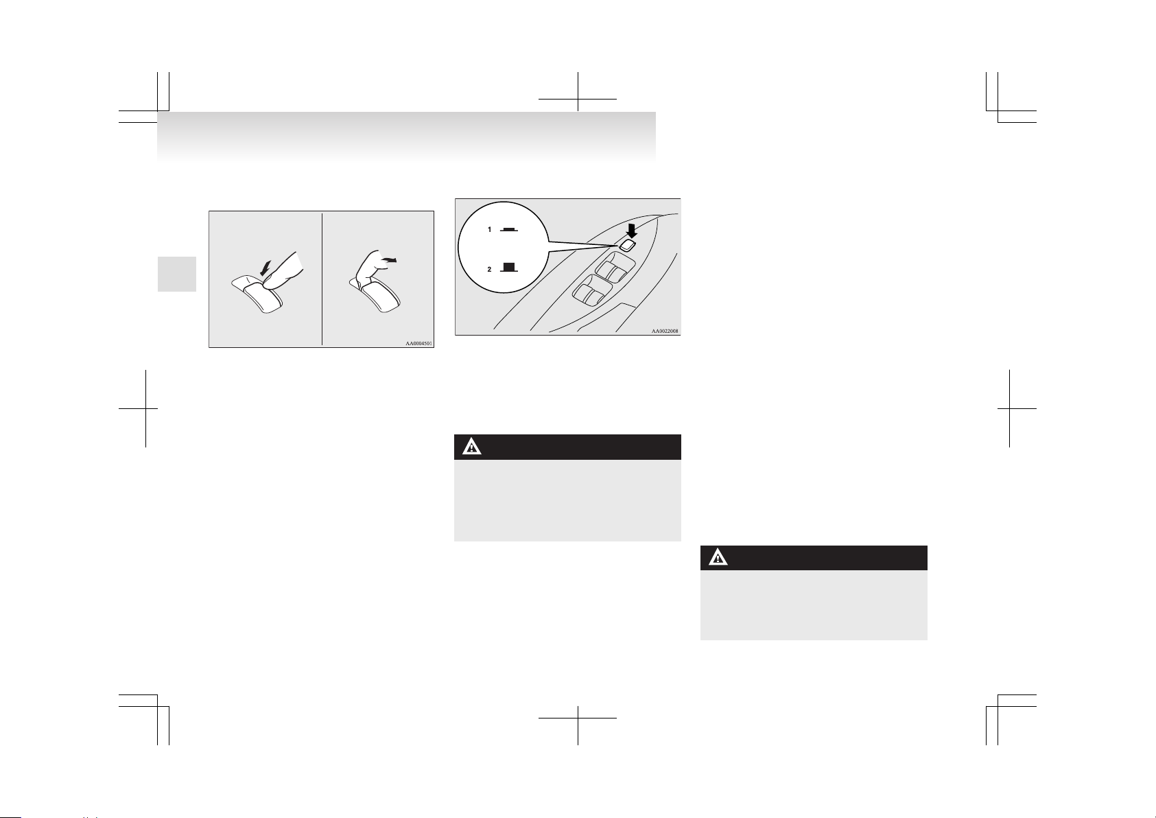
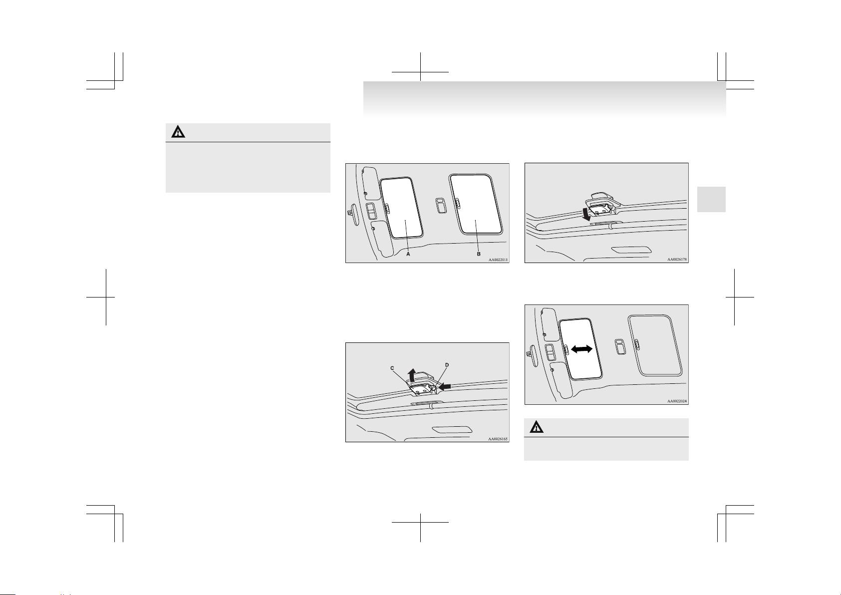
Sunroof*
E00302700496
There are two sunroofs.
A- Front sunroof
B- Rear sunroof
Front sunroof
To tilt up
Push the handle (C) while pressing the button (D).
To tilt down
Pull the handle, returning it to its original position
and securing it in place.
Sunshade
Slide the sunshade manually to open and close it.
CAUTION
l
Be careful that hands are not trapped
when closing the sunshade.
Locking and unlocking
1-13
1
Page 33
NOTE
l
Be sure to tilt down the sunroof before closing the sunshade.
l
The sunshade cannot be closed with the sunroof opened. Do not attempt to close the sunshade when the sunroof is opened.
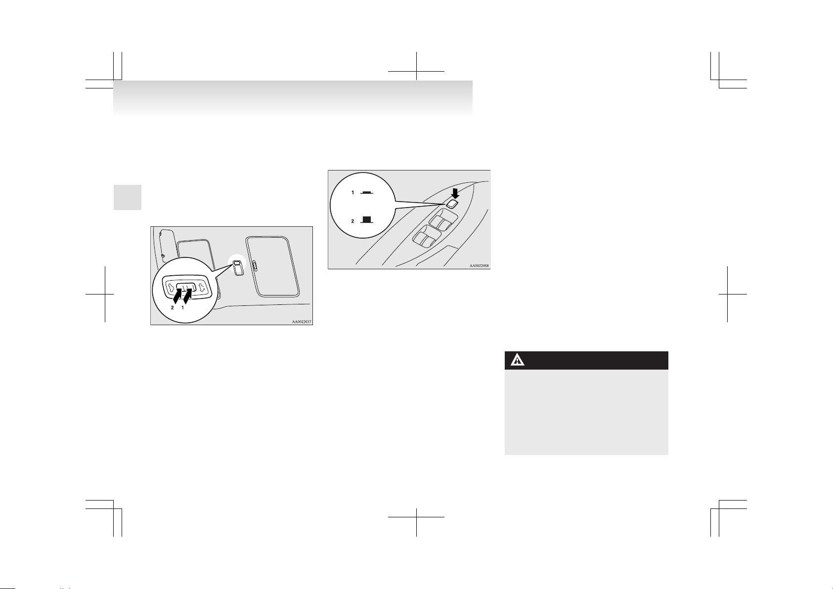
Rear sunroof
The rear sunroof can only be operated with the ignition switch in the “ON” position.
To open
The sunroof automatically opens if the switch (1) is
pressed. To stop the moving sunroof, press the
switch (2).
NOTE
l
The sunroof automatically stops just before
reaching the fully open position.
Press the switch again to fully open it.
To close
The sunroof automatically closes if the switch (2)
is pressed.
To stop the moving sunroof, press switch (1)
Lock switch
When this switch is operated, the sunroof switch
cannot be used to open or close the sunroof.
To unlock, press it once again.
1- Lock
2- Unlock
NOTE
l
If the sunroof switch is operated with the
lock switch pressed, a buzzer sounds to indicate the sunroof cannot be opened or closed.
l
With the lock switch pressed, operation of
the power windows with switches other than
the driver’s door switches is also prevented.
Safety mechanism
If a hand or head is trapped in the closing sunroof,
it will reopen automatically.
Nonetheless, make sure that nobody puts their head
or hand out of the sunroof when opening or closing.
The opened sunroof will become operational after
a few seconds.
If the safety mechanism should be activated 5 or
more times consecutively, normal closing of the sunroof will be aborted. In such an event, the following steps should be taken:
1. Press the switch (2) repeatedly to fully close
the sunroof and hold the switch (2) for a period of at least 3 seconds.
2. After pressing the switch (1) to perform full
opening, press the switch (2) to fully close
the sunroof.
NOTE
l
The safety mechanism can be activated if the
driving conditions or other circumstances
cause the sunroof to be subjected to a physical shock similar to that caused by a trapped
hand or head.
l
Avoid stopping the sunroof before it reaches
the opening or closing end during operations.
If this should accidentally happen, repeat the
process from step 1.
3. Following this action, it should be possible
to operate the sunroof in the normal manner.
WARNING
l
Do not put head, hands or anything else
out of the sunroof opening while driving
the vehicle.
l
Never leave a child (or other person who
might not be capable of safe operation of
the sunroof switch) in the vehicle alone.
l
Before operating the sunroof, make sure
that nothing is capable of being trapped
(head, hand, finger, etc.).
Locking and unlocking
1-14
1
Page 34
CAUTION
l
The safety mechanism is cancelled just before the sunroof is fully closed. This allows the sunroof to close completely.
Therefore be especially careful that no fingers are trapped in the sunroof.
NOTE
l
The sunroof stops just before reaching the
fully open position.
If the vehicle is driven with the sunroof in
this position, wind throb is lower than with
the sunroof fully open.
l
When leaving the vehicle unattended, make
sure you close the sunroof and remove the ignition key.
l
Do not try to operate the sunroof if it is frozen closed (after snow fall or during extreme
cold).
l
Do not sit or place heavy luggage on the sunroof or roof opening edge.
l
Release the switch as soon as the sunroof reaches the fully open or fully closed position.
l
If the sunroof does not operate when the sunroof switch is operated, release the switch
and check whether something is trapped by
the sunroof. If nothing is trapped, we recommend you to have the sunroof checked.
l
Depending on the model of ski carriers or
roof carriers, the sunroof may make contact
with the carrier when the sunroof is tilted up.
Be careful when tilting up the sunroof if such
a ski carrier or a roof carrier is installed.
l
Be sure to close the sunroof completely
when washing the vehicle or when leaving
the vehicle.
l
Be careful, not to put any wax on the weatherstrip (black rubber) around the sunroof
opening. If stained with wax, the weatherstrip cannot maintain a weatherproof seal
with the sunroof.
l
After washing the vehicle or after it has
rained, wipe off any water that is on the sunroof before operating it.
l
Operating the sunroof repeatedly with the engine stationary will run down the battery. Operate the sunroof while the engine is running.
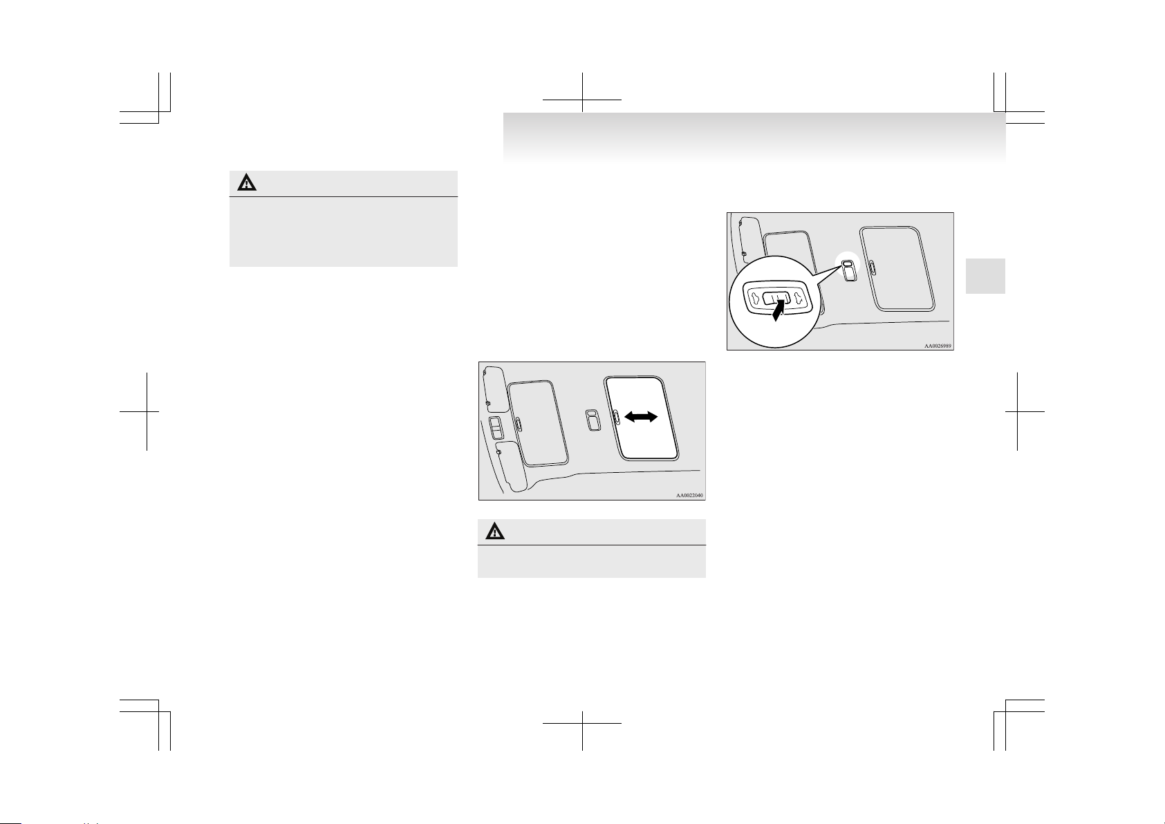
Sunshade
Slide the sunshade manually to open and close it.
CAUTION
l
Be careful that hands are not trapped
when closing the sunshade.
By the following operation, the sunshade will open
together with the sunroof.
To open
When the switch is pressed, the sunshade will open
together with the sunroof.
NOTE
l
The sunshade cannot be closed with the sunroof opened. Do not attempt to close the sunshade when the sunroof is opened.
Locking and unlocking
1-15
1
Page 35

Page 36
Seat...............................................................................................2-02
Seat arrangement..........................................................................2-03
Seat adjustment.............................................................................2-05
Front seat......................................................................................2-05
Second seat...................................................................................2-07
Third seat*....................................................................................2-10
Head restraints..............................................................................2-11
Making a luggage area..................................................................2-13
Making a flat seat.........................................................................2-14
Seat belts.......................................................................................2-17
Pregnant women restraint.............................................................2-20
Seat belt pretensioner system and force limiter system................2-20
Child restraint...............................................................................2-21
Seat belt inspection.......................................................................2-29
Supplemental restraint system (SRS) - airbag..............................2-29
Seat and seat belts
2
Page 37
Seat
E00400101449
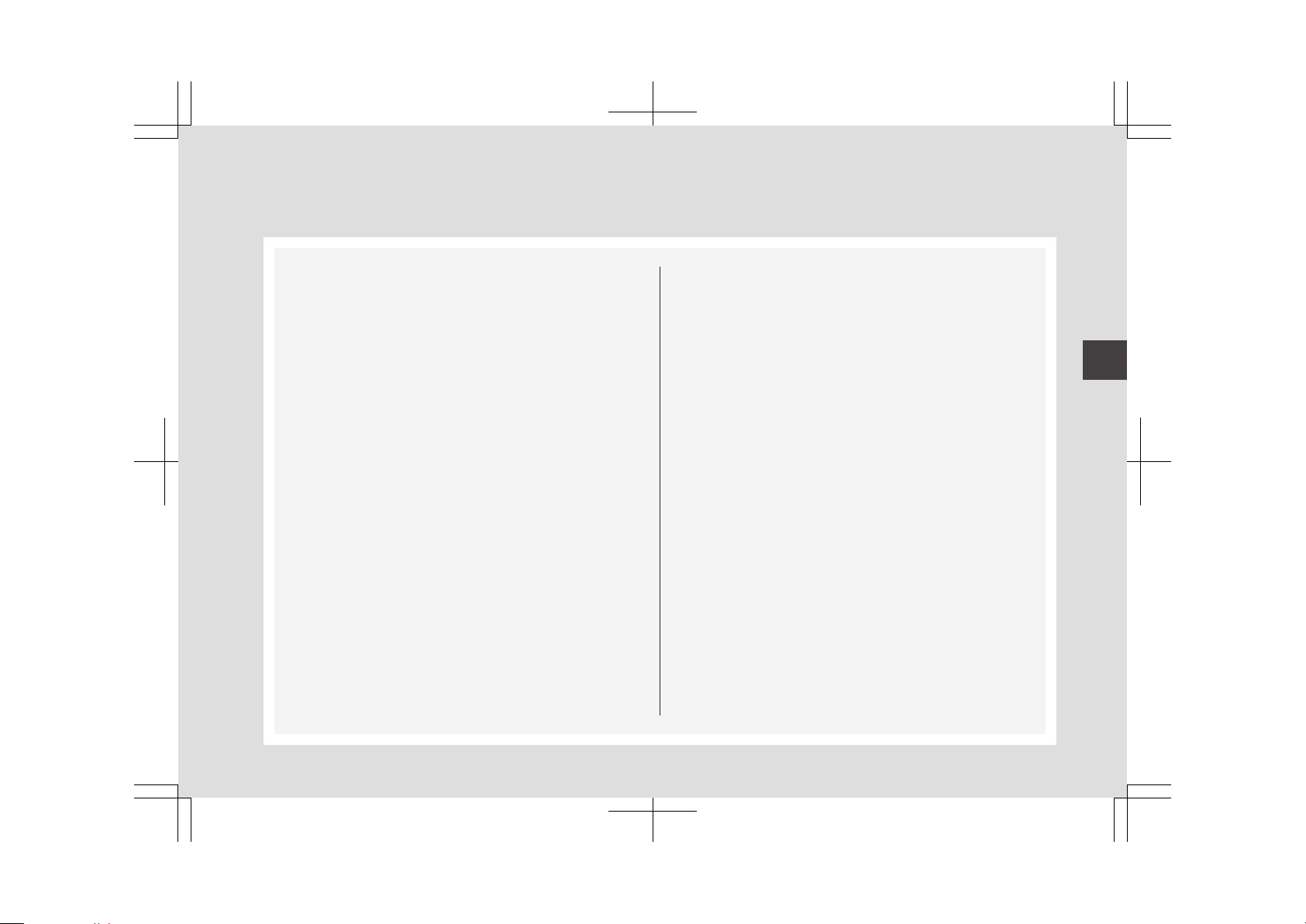
6-person seat 7-person seat
1-Front seat
l
To adjust forward or backward ® p. 2-05
l
To recline the seatback ® p. 2-06
l
To adjust seat cushion height ® p. 2-06
l
Armrest* ® p. 2-06
l
Heated seats* ® p. 2-06
2- Second seat
l
To adjust forward or backward ® p. 2-07
l
To recline the seatback ® p. 2-07
l
Armrest ® p. 2-08
l
To get in and out of the third seat ® p. 2-08
l
Folding up the seat cushion ® p. 2-09
3-Third seat*
l
To recline the seatback ® p. 2-10
l
Folding the seatbacks forward ® p. 2-11
l
Stowing the third seat ® p. 2-13
Seat and seat belts
2-02
2
Page 38

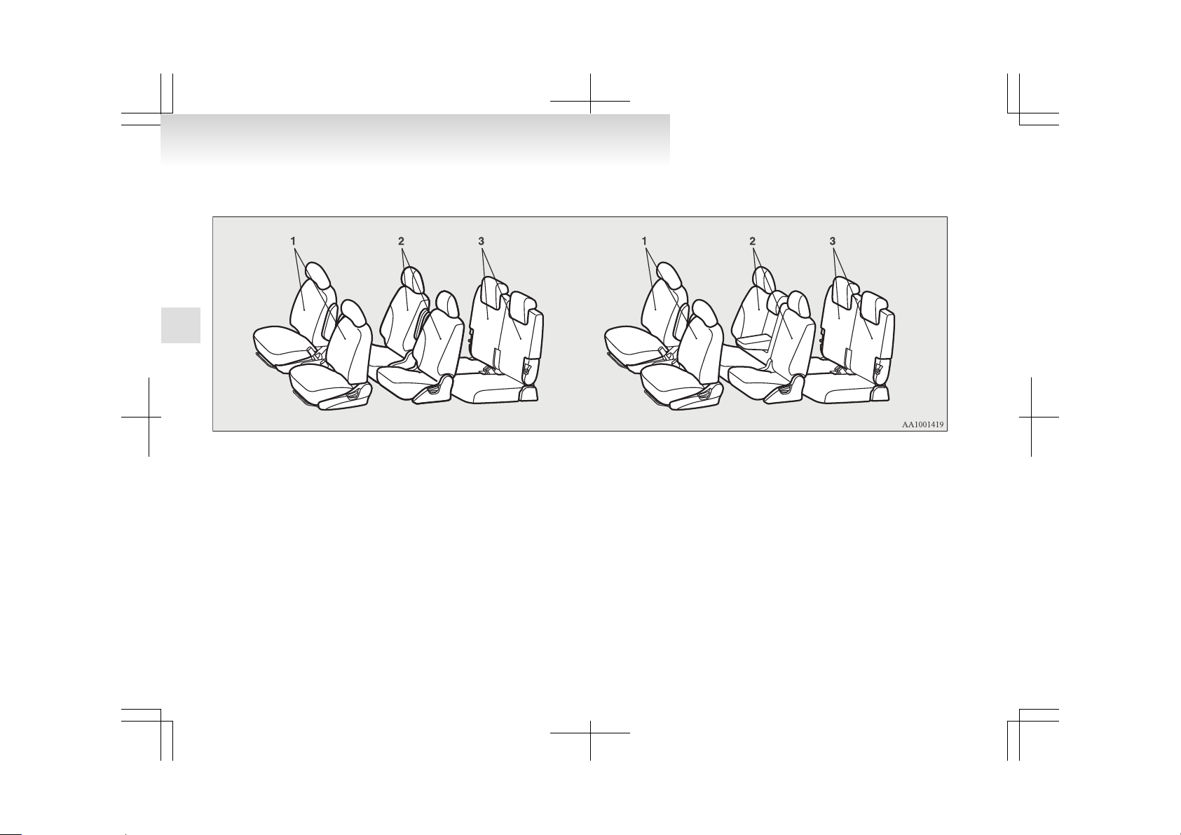
Seat arrangement
E00400200645
By operating the seats, select the desired seats arrangement.
6 - person seat 7 - person seat
Normal usage
Flat seat
With front and second seats ® p. 2-15
With second and third seats ® p. 2-16
Seat and seat belts
2-03
2
Page 39
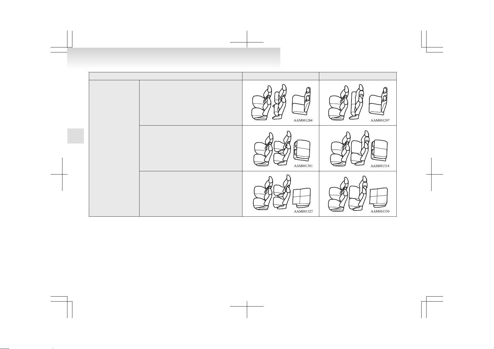
6 - person seat 7 - person seat
How to stow large articles
Folding up the second seat cushion ® p. 2-09
Folding the third seatbacks forward ® p. 2-11
Stowing the third seat ® p. 2-13
Seat and seat belts
2-04
2
Page 40
Seat adjustment
E00400300402
Adjust the driver’s seat so that you are comfortable
and that you can reach the pedals, steering wheel,
switches etc. while retaining a clear field of vision.
WARNING
l
Do not attempt to adjust the seat while
driving. This can cause loss of vehicle control and result in an accident. After adjustments are made, ensure the seating is
locked in position by attempting to move
the seat forward and rearward without using the adjusting mechanism.
l
It is extremely dangerous to ride in the
luggage area of a vehicle. Also, the luggage area and rear seats should never be
used as a play area by children. In a collision, people or children riding unrestrained in these areas are more likely to be seriously injured or killed.
Do not allow people or children to ride in
any area of your vehicle that is not equipped with seats and seat belts, and make
sure that everyone travelling in your vehicle is in a seat and wearing a seat belt, or
in the case of a child is strapped in a child
restraint.
WARNING
l
To minimize the risk of personal injury
in the event of a collision or sudden braking, the seatbacks should always be in the
almost upright position while the vehicle
is in motion. The protection provided by
the seat belts may be reduced significantly when the seatback is reclined. There is
greater risk that the passenger will slide
under the seat belt, resulting in serious injury, when the seatback is reclined.
CAUTION
l
Make sure the seat is adjusted by an
adult or with adult supervision for correct and safe operation.
l
Do not place a cushion or the like between your back and the seatback while
driving. The effectiveness of the head restraints will be reduced in the event of an
accident.
l
When sliding the seats, be careful not to
catch your hand or foot.
l
When sliding or reclining the seat rearward, pay careful attention to the rear
seat passengers.
Front seat
E00400400012
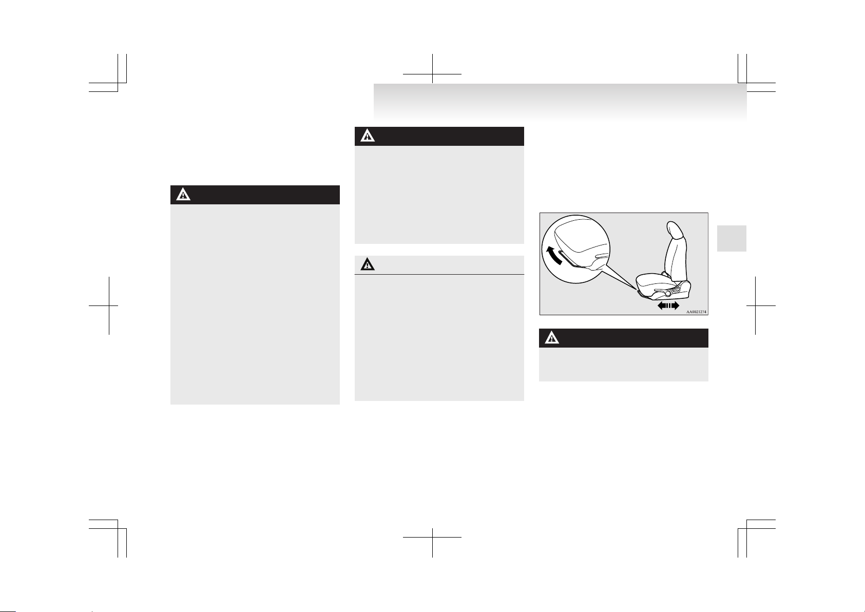
To adjust forward or backward
E00400500491
Pull the seat adjusting lever and adjust the seat forward or backward to the desired position. After adjustment, release theadjusting lever to lock the seat
in position.
WARNING
l
To ensure the seat is locked securely, try
to move the seat forward or backward
without using the adjusting lever.
Seat and seat belts
2-05
2
Page 41
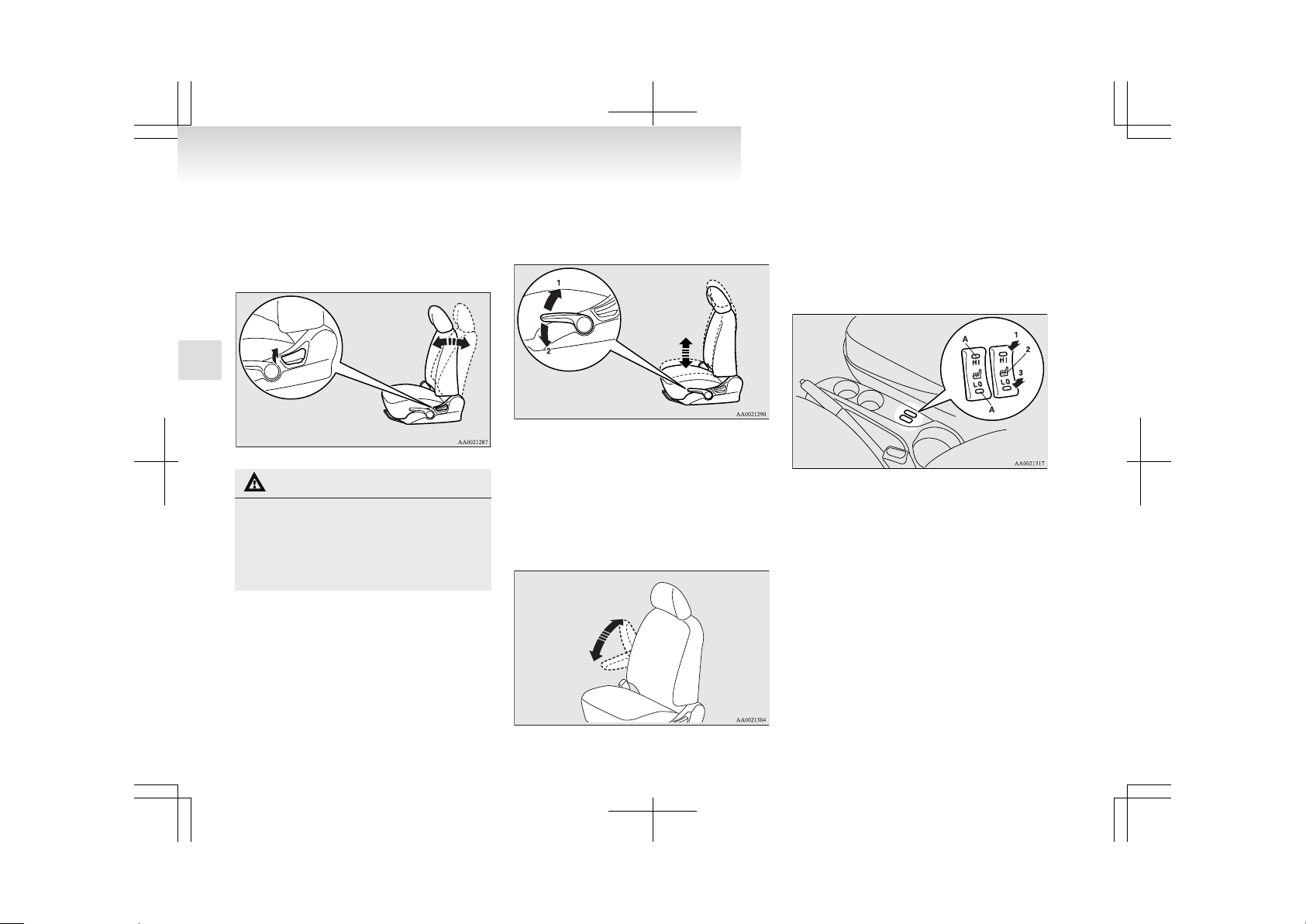
To recline the seatback
E00400600610
In order to recline the seatback, lean forward slightly, pull the seatback lock lever up, and then lean
backward to the desired position and release the lever. The seatback will lock in that position.
CAUTION
l
The reclining mechanism of the seatback
is spring loaded, causing it to return to
the vertical position when the lock lever
is operated. When using the lever, sit
close to the seatback or hold it with your
hand to control its return motion.
To adjust seat height
E00400700871
Adjust the seat cushion height by repeatedly operating the lever.
1- Raise
2- Lower
Armrest*
E00400900365
To adjust the armrest angle, tip the armrest forward
and then raise it to the desired position.
To return the armrest to its original position, raise
it backward.
NOTE
Do not stand or sit on the armrest. It could break.
Heated seats*
E00401100667
The heated seats can be operated with the ignition
switch in the “ON” position.
1-Heater high (for quick heating).
2-Heater off.
3-Heater low (to keep the seat warm).
The indication lamp (A) will illuminate while the
heater is on.
Seat and seat belts
2-06
2
Page 42

CAUTION
l
Operate in the high position for quick heating. Once the seat is warm, set the heater
to low to keep it warm. Slight variations
in seat temperature may be felt while using the heated seats. This is caused by the
operation of the heater’s internal thermostat and does not indicate a malfunction.
l
If the following types of persons use the
heated seats, they might become too hot
or receive minor burns (red skin, heat blisters, etc.):
• Children, elderly or ill people
• People with sensitive skin
• Excessively tired people
• People under the influence of alcohol
or sleep inducing medication (cold
medicine, etc.)
l
Do not use a blanket, cushion, or other material with high heat insulation properties
on the seat while using the heater; this
might cause the heater element to overheat
l
Turn the heater off immediately if it appears to be malfunctioning during use.
NOTE
l
Do not place heavy objects on the seat or
stick pins, needles, or other pointed objects
into it.
l
When cleaning the seat, do not use benzene,
kerosene, petrol, alcohol, or other organic solvents; these might damage the surface of the
seat and also the heater element.
l
If water or any other liquid is spilled on the
seat, allow it to dry thoroughly before attempting to use the heater.
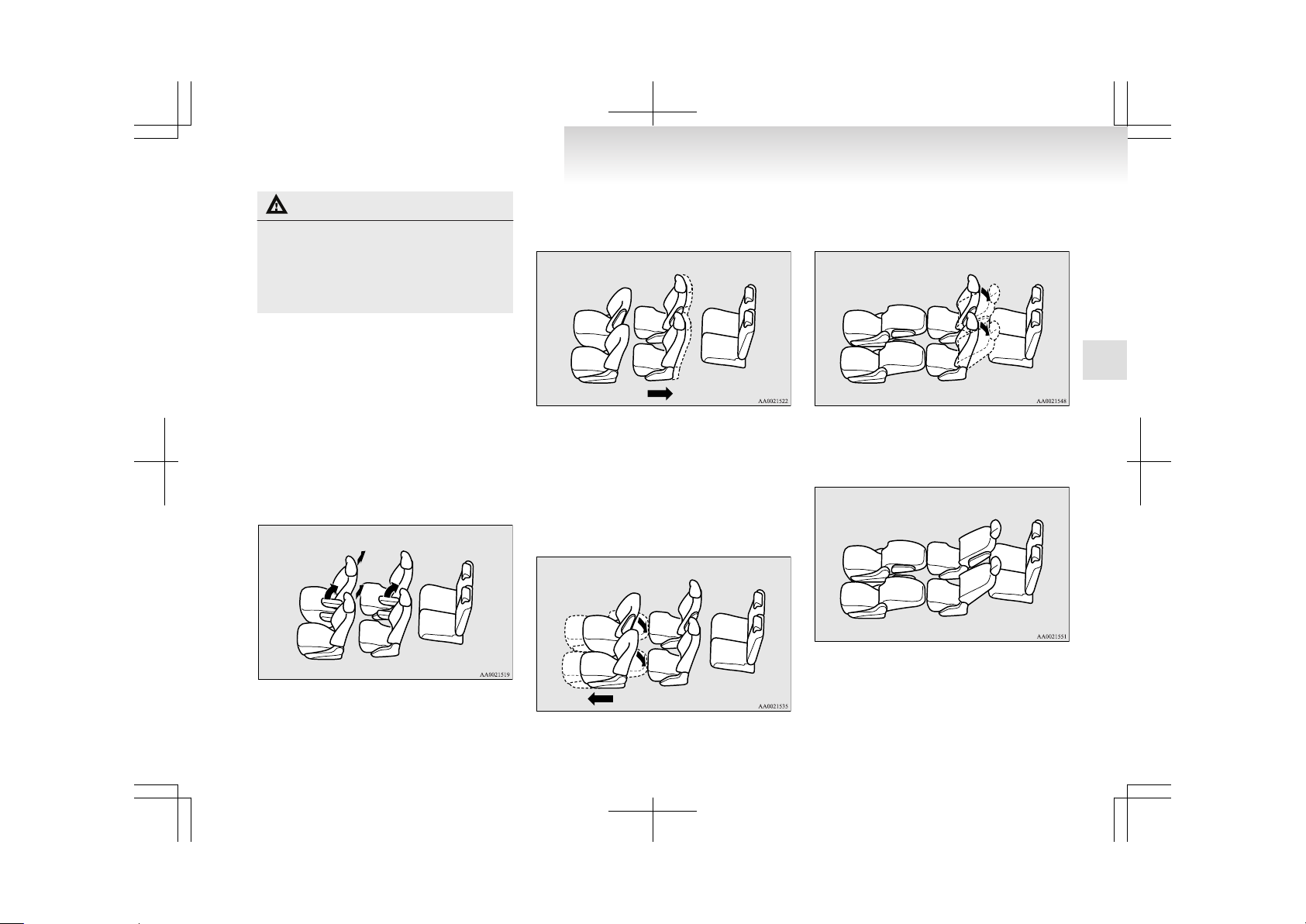
Second seat
E00402000227
When a person is sitting in the middle seating position of the second seat in a cabin with 7-person
seats, adjust the head restraints to heights at which
they lock in position. Refer to “Head restraints” on
page 2-11.
NOTE
l
It is possible to adjust each side of the second seats forward and backward independently of the other side, to adjust the seatback angle independently on each side, and to fold
up the seat cushion independently on each
side.
To adjust forward or backward
E00402100097
Pull the seat adjusting left- or right-hand lever and
adjust the seat forward or backward to the desired
position. After adjustment, release the adjusting lever to lock the seat in position.
6-person seat
7-person seat
WARNING
l
To ensure the seat is locked securely, try
to move the seat forward or backward
without using the adjusting lever.
To recline the seatback
E00402200186
In order to recline the seatback, lean forward slightly, pull the seatback lock lever up, and then lean
backward to the desired position and release the lever. The seatback will lock in that position.
6-person seat
Seat and seat belts
2-07
2
Page 43

7-person seat
WARNING
l
When a person is sitting in the middle seating position of the second seat in a cabin
with 7-person seats, the two sides of the
second seat must have the same forward/
backward position and the same seatback
angle. Otherwise, the seat belt for the middle seating position may not be adequately effective in the event of hard braking
or a collision.
CAUTION
l
The reclining mechanism of the seatback
is spring loaded, causing it to return to
the vertical position when the lock lever
is operated. When using the lever, sit
close to the seatback or hold it with your
hand to control its return motion.
Armrest
E00402400250
6 - person seat
To adjust the armrest angle, tip the armrest forward
and then raise it to the desired position.
To return the armrest to its original position, raise
it backward.
7 - person seat
To use the armrest, fold it down.
To return to the original position, push it backward
(into the seatback) until it is level with the seat.
NOTE
l
Do not stand or sit on the armrest. It could
break.
To get in and out of the third seat
E00402500222
The lever can be used to make getting in and out
easier.
1- 1- To get in or out
2- 2- To get out
Fold the seatback forward, then slide the entire seat
forward. To return the seat, slide the entire seat
fully backward to retain it and then raise the seatback.
After returning the seat, gently try to move it forward and backward to check that it is securely retained.
Seat and seat belts
2-08
2
Page 44

WARNING
l
Do not drive the vehicle with the seatback
folded forward. The seat is not retained
with the seatback in this position, so serious injuries could be suffered in the event
of hard braking or a collision.
CAUTION
l
The reclining mechanism of the seatback
is spring loaded, causing it to return to
the vertical position when the lock lever
is operated. When using the lever, sit
close to the seatback or hold it with your
hand to control its return motion.
l
Use a foot to operate the pedal (2).
Folding up the seat cushion
E00409700021
It is possible to create a luggage area by folding up
the seat cushion and moving the seat forward.
WARNING
l
Do not allow a passenger to sit on the seat
or a child to play on it with the seat cushion folded up.
Otherwise, serious injuries could be suffered in the event of hard braking.
CAUTION
l
Do not stack luggage above the seatback
height. Secure the luggage firmly.
Otherwise, serious accidents could result
due to restricted rear vision or unrestrained objects entering the passenger compartment during sudden braking.
To fold
1. If the seatback is reclined, raise it to the initial locked position. (Refer to “To recline the
seatback” on page 2-07.)
2. With the lever pulled on the side you wish to
fold, fold up the seat cushion.
6-person seat
7-person seat
To return
With the lever pulled, return the seat cushion to its
original position.
Then, check that the seat is securely retained.
NOTE
l
With the seat in its most forward position,
the seat cushion cannot be returned to its original position.
To adjust the seat forward or backward with the seat cushion folded up
Adjust the seat forward or backward with the lever
pulled.
Seat and seat belts
2-09
2
Page 45

After making the adjustment, gently try to move it
forward and backward to check that it is securely retained.
6-person seat
7-person seat
NOTE
l
The seat can slide further forward only when
the seat cushion is folded up.
To adjust the seat cushion angle
E00410300014
If, while raising the seat cushion, you release the
lever when the seat cushion reaches some desired
angle, the seat cushion will be held at that angle.
6-person seat
7-person seat
Third seat*
E00402700282
When sitting in the third seat, adjust the head restraints to heights at which they lock in position. Refer to “Head restraints” on page 2-11.
To recline the seatback
E00402800140
In order to recline the seatback, lean forward slightly, pull the seatback lock lever up, and then lean
backward to the desired position and release the lever. The seatback will lock in that position.
NOTE
l
It is possible to adjust the seatback angle independently on each side of the seats.
Seat and seat belts
2-10
2
Page 46
CAUTION
l
The reclining mechanism of the seatback
is spring loaded, causing it to return to
the vertical position when the lock lever
is operated. When using the lever, sit
close to the seatback or hold it with your
hand to control its return motion.
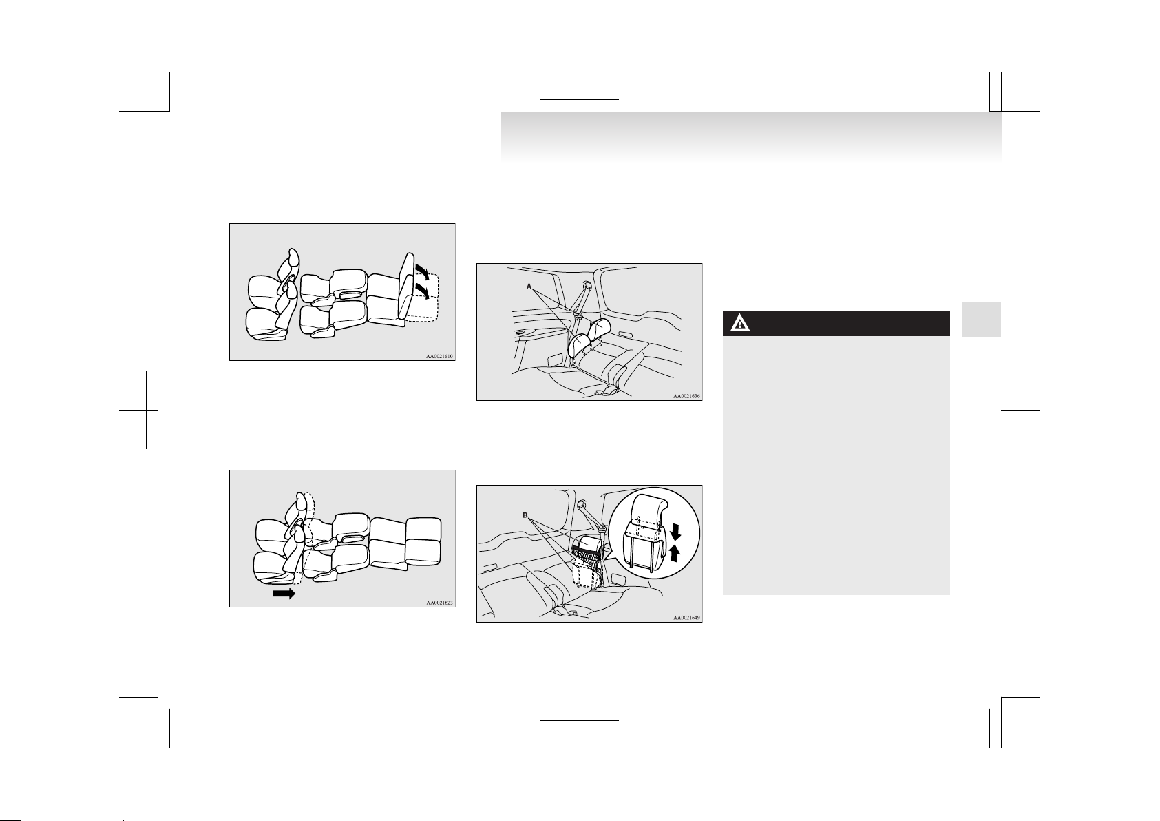
Folding the seatbacks forward
E00402900024
Larger objects can be loaded into the vehicle if a
seatback is folded forwards.
WARNING
l
The luggage compartment in the rear of
the vehicle should never be used as a play
area by children. Children should be seated with seat belts fastened when the vehicle is in motion. Be sure that the rear seatbacks are returned to their fully upright
position and locked in place.
CAUTION
l
Do not stack luggage above the seatback
height. Secure the luggage firmly.
Otherwise, serious accidents could result
due to restricted rear vision or unrestrained objects entering the passenger compartment during sudden braking.
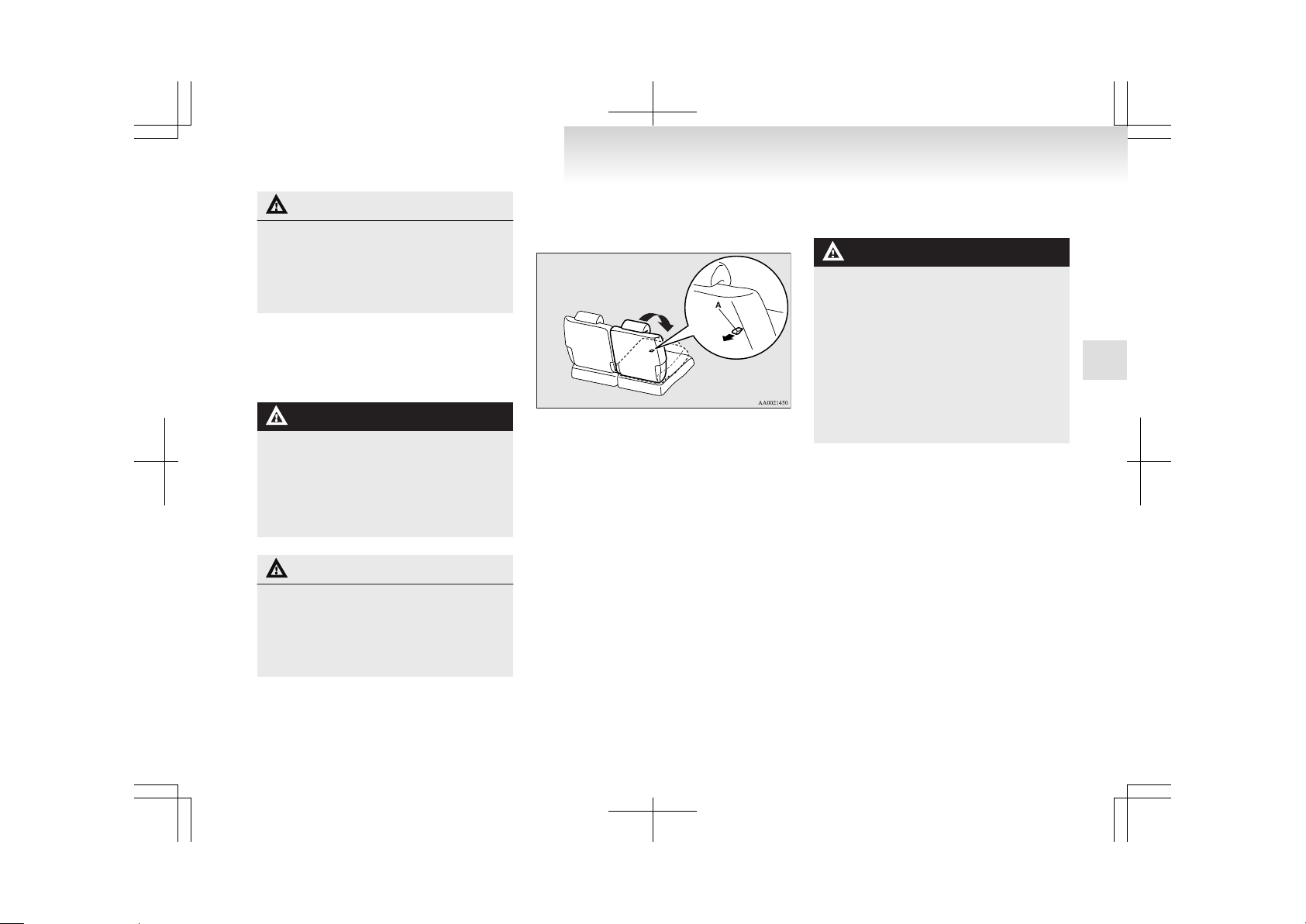
To fold
Pull the belt (A) behind the seatback that you wish
to fold, then tilt the seatback forwards until it locks.
To return
1. Pull the belt (A) behind the seatback which
is desired to be raised, then raise the seatback
until it locks securely into place.
2. Push lightly on the seatback to confirm that
it has actually been secured.
Head restraints
E00403301240
WARNING
l
Driving without the head restraints in
place can cause you and your passengers
serious injury or death in an accident. To
reduce the risk of injury in an accident, always make sure the head restraints are installed and properly positioned when the
seat is occupied.
l
Never place a cushion or similar device
on the seatback. This can adversely affect
head restraint performance by increasing
the distance between your head and the
restraint.
To adjust height
Adjust the head restraint height so that the centre
of the restraint is as close as possible to eye level to
reduce the chances of injury in the event of collision. Any person too tall for the restraint to reach
their seated eye level, should adjust the restraint as
high as possible.
Seat and seat belts
2-11
2
Page 47
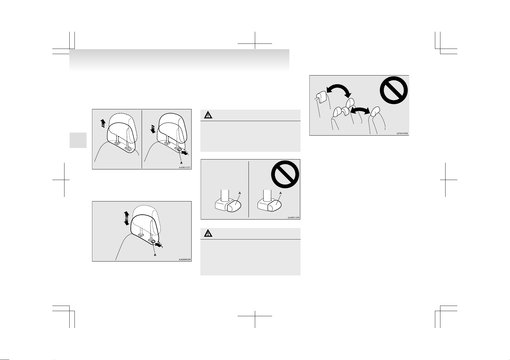
To raise the head restraint, move it upward. To lower the restraint, move it downward while pushing
the height adjusting knob (A) in the direction of the
arrow. After adjustment, push the head restraint
downward and make sure that it is locked.
To remove
Lift the head restraint with the height adjusting
knob (A) pushed in.
To install
Confirm that the head restraint is facing the correct
direction, and then insert it into the seatback while
pressing the height adjusting knob (A) in the direction indicated by the arrow.
CAUTION
l
Confirm that the height adjusting knob
(A) is correctly adjusted as shown in the
illustration, and also lift the head restraints to ensure that they do not come
out of the seatback.
CAUTION
l
The head restraints for the seats differ in
shape and size. When installing head restraints, make sure the head restraints
are fitted in their respective seats.
Failure to do so could cause serious injury if involved in an accident.
Seat and seat belts
2-12
2
Page 48

Making a luggage area
E00403400039
WARNING
l
If required, always operate the seating before the vehicle is in motion.
l
After seat operations are made, ensure
the seating is locked in position by attempting to move the seat and seatback forward and rearward without using the adjusting mechanism.
l
The luggage compartment in the rear of
the vehicle should never be used as a play
area by children. Children should be seated with seat belts fastened when the vehicle is in motion. Be sure that the rear seatbacks are returned to their fully upright
position and locked in place.
CAUTION
l
Do not stack luggage above the seatback
height.
Secure the luggage firmly.
Otherwise, serious accidents could result
due to restricted rear vision or unrestrained objects entering the passenger compartment during sudden braking.
l
Make sure that the seat is operated by an
adult. If it is operated by a child, an unexpected accident might occur.
l
When folding or storing the seat, be sure
not to catch your hand or leg.
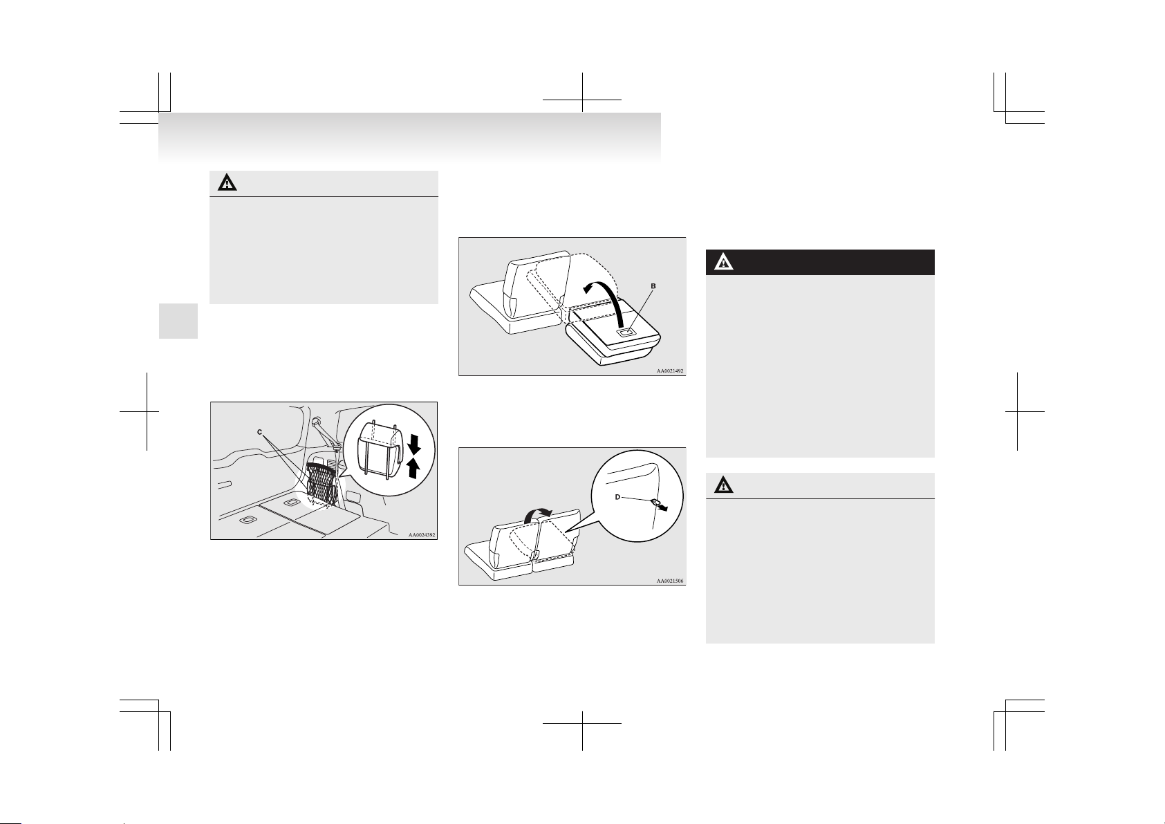
Stowing the third seat
E00404100020
The third seat can be stowed under the floor to create a luggage area.
NOTE
l
Each side of the third seats can be stowed independently of the other.
To stow
1. Remove the head restraints from the third
seats. (Refer to “Head restraints” on page
2-11.)
2. Fold the seatback forward and make sure it is
securely retained against the seat cushion.
(Refer to “Folding the seatbacks forward” on
page 2-11.)
NOTE
l
The seatback cannot be retained if any object
is trapped between the seatback and seat cushion.
l
If the seatback is not retained against the seat
cushion when the seat is stowed, it may get
caught on the floor and prevent the seat from
being returned to its original position.
3. Pull the belt (A) on the back of the seat cushion until it clicks.
4. Tip the entire seat backward. Hold the handle (B) on the back of the seat cushion and
lower the seat into the floor.
Seat and seat belts
2-13
2
Page 49
CAUTION
l
When stowing the seat, hold it with your
hands and lower it slowly. Unless you
hold the seat securely, it may suddenly tip
under its own weight, trapping your
hands.
l
Do not pull the belt while a person is sitting on the seat. The seat could tip backward, resulting in an accident.
NOTE
l
The removed third seat head restraints (C)
can be fitted together and stored in the cargo
net in the luggage area. (Refer to “Cargo net”
on page 5-45.)
To return
1. Use the handle (B) to lift the entire seat. Slowly tip the seat forward, then push it until it
locks securely in position.
2.
Pull the belt (D) on the back of the seatback.
With the belt pulled, raise the seatback to its
original position.
3. After raising the seatback to its original position, push lightly on it to confirm that it has
been secured.
4. Install the head restraints.
Making a flat seat
E00404300064
By removing the head restraints and fully reclining
the seatbacks of the seats, one large flat seat is achieved.
WARNING
l
Never drive with luggage or passengers
on the flat seat. This is highly dangerous.
In a collision, people or children riding unrestrained in these areas are more likely
to be seriously injured or killed.
Do not allow people or children to ride in
any area of your vehicle that is not equipped with seats and seat belts, and make
sure that everyone travelling in your vehicle is in a seat and wearing a seat belt, or
in the case of a child is strapped in a child
restraint.
In the interest of their safety, children
should not be allowed to adjust the seats.
CAUTION
l
To make a flat seat, stop the vehicle in a
safe place.
l
Make sure that the seat is adjusted by an
adult. If it is adjusted by a child, an unexpected accident might occur.
l
When sliding the seat, be sure not to
catch your hand or leg.
l
Do not walk around on top of the seats after they have been laid flat.
l
To ensure the seats are locked securely, attempt to move them back and forth.
Seat and seat belts
2-14
2
Page 50
CAUTION
l
Do not jump on, or impact the seatbacks
heavily.
l
To raise the seatback, sit on the seat and
put a hand on the seatback and raise slowly. Never have a child do this operation,
or an unexpected accident may result.
With front and second seats
E00404400023
NOTE
l
Retract the personal table to its original position before performing the following steps.
(Refer to “Personal table” on page 5-42.)
1. Remove the head restraints from the front
seats, and raise the armrest. (Refer to “Head
restraints” on pages 2-11. Also refer to “Armrest” on pages 2-06, 2-08.)
2. Slide the second seats to the fully backward
position. (Refer to “To adjust forward or backward” on page 2-07.)
3. Adjust the second seat cushions to the highest angle. (Refer to “To adjust the seat cushion angle” on page 2-10.)
4. Slide the front seats to the fully forward position, then tip their seatbacks backward. (Refer to “To adjust forward or backward” on
page 2-05 and “To recline the seatback” on
page 2-06.)
5. Tip the seatbacks of the second seats backwards. (Refer to “To recline the seatback” on
page 2-07.)
6. The flat seat configuration is now complete.
To return the seats to the normal position, reverse the procedure above.
Seat and seat belts
2-15
2
Page 51

NOTE
l
The removed head restraints (A) can be fitted
together and stored in the cargo net in the luggage area. (Refer to “Cargo net” on page
5-45.)
With second and third seats
E00404500024
NOTE
l
Retract the personal table to its original position before performing the following steps.
(Refer to “Personal table” on page 5-42.)
1. Remove the head restraints from the second
and third seats, and raise the armrest. (Refer
to “Head restraints” on page 2-11 and “Armrest” on page 2-08.)
2. Slide the front seats to the fully forward position. (Refer to “To adjust forward or backward” on page 2-05.)
3. Slide the second seats to the fully forward position. (Refer to “To adjust forward or backward” on page 2-07.)
4. Tip the seatbacks of the second seats backwards. (Refer to “To recline the seatback” on
page 2-07.)
Seat and seat belts
2-16
2
Page 52
5. Tip the seatbacks of the third seats backward. (Refer to “To recline the seatback” on
page 2-10.)
6. Move the front seats backward until they
touch the second seats. Lock them in that position. The flat seat configuration is now complete.
To return the seats to their normal positions,
reverse the above procedure.
NOTE
l
You can store the head restraints (A) removed from the second seat (except the middle seating position) by inserting their rods
between the tipped third seat and the wall of
the luggage area on the right side.
l
The head restraints (B) removed from the
third seat and the second seat (the middle seating position) can be fitted together and stored in the cargo net in the luggage area.
Seat belts
E00404800593
To protect you and your passengers in the event of
an accident, it is most important that the seat belts
be worn correctly while driving.
The front seat belts have a pretensioner system.
These belts are used the same way as a conventional seat belt.
Refer to “Seat belt pretensioner system and force
limiter system” on page 2-20 .
WARNING
l
Always place the shoulder belt over your
shoulder and across your chest. Never
put it behind you or under your arm.
l
One seat belt should be used by only one
person.
Doing otherwise can be dangerous.
l
The seat belt will provide its wearer with
maximum protection if the recliner seatback is placed in fully upright position.
When the seatback is reclined, there is
greater risk that the passenger will slide
under the belt, especially in a forward impact accident, and may be injured by the
belt or by striking the instrument panel
or seatbacks.
l
Seat belts should always be worn by every adult who drives or rides in this vehicle, and by all children who are tall
enough to wear seat belts properly.
l
Remove any twists when using the belt.
Seat and seat belts
2-17
2
Page 53
WARNING
l
No modifications or additions should be
made by the user which will either prevent the seat belt adjusting devices from
operating to remove slack, or prevent the
seat belt assembly from being adjusted to
remove slack.
l
To reduce risk of serious or fatal injury
in an accident, including the deploying
driver airbag, the driver should adjust
the driver’s seat to the rear most position
that still allows good visibility and good
control of the steering wheel, the brake
and accelerator, and vehicle controls.
l
Never hold a child in your arms or on
your lap when riding in this vehicle, even
if you are wearing your seat belt. To do
so risks severe or fatal injury to your
child in a collision or sudden stop.
l
Always adjust the belt to a snug fit.
3-point type seat belt (with emergency locking mechanism)
E00404900754
This type of belt requires no length adjustment.
Once worn, the belt adjusts itself to the movement
of the wearer, but in the event of a sudden or strong
shock, the belt automatically locks to hold the wearer’s body.
To fasten
1. Pull the seat belt out slowly while holding
the latch plate.
NOTE
l
When the seat belts cannot be pulled out in a
locked condition, pull the belts once forcefully and then return them. After that, pull the
belts out slowly once again.
2. Insert the latch plate into the buckle until a
“click” is heard.
WARNING
l
Never wear the lap portion of the belt
across your abdomen. During accidents it
can press sharply against the abdomen
and increase the risk of injury.
l
The seat belts must not be twisted when
worn.
3. Pull the belt slightly to adjust slackness as desired.
To unfasten
Hold the latch plate and push the button on the buckle.
NOTE
l
As the belt retracts automatically, keep holding the latch plate while retracting so that the
belt stows slowly. Failure to do this could
damage the vehicle.
Seat and seat belts
2-18
2
Page 54

Seat belt reminder/warning lamp
E00409800774
A tone and warning lamp are used to remind the
driver to fasten the seat belt.
NOTE
l
For the front passenger seat, the warning function works only while a person is sitting on
the seat.
When the ignition key is turned to the “ON” position, the warning lamp will illuminate and a tone
will sound for about 6 seconds. If the driver’s seat
belt remains unfastened for approximately
1 minute later, the warning lamp will flash and the
tone sound intermittently (each 12 times) when the
vehicle is driven. If the driver subsequently unfastens the seat belt while driving, the warning lamp
and tone will issue further warnings. And if the
seat belt remains unfastened, the warning lamp and
tone will issue further warnings each time the vehicle starts moving from a stop. When the seat belt is
fastened, the warnings will stop.
WARNING
l
In order to reduce the risk of serious or fatal injury in an accident, always wear
your own seat belt. Do not allow anyone
to ride in your vehicle unless he or she is
also seated and wearing a seat belt. Children should additionally be restrained in
a secure child restraint system.
NOTE
l
When luggage is placed on the front passenger seat, a sensor in the seat cushion may, depending on the weight and position of the luggage, cause the warning tone to sound and
the warning lamp to come on.
Adjustable seat belt anchor (front seats)
E00405000433
The seat belt anchor height can be adjusted.
Move the seat belt anchor (A) down with the lock
knob (B) depressed. To move the anchor up, slide
it without depressing the lock knob.
WARNING
l
When adjusting the seat belt anchor, set
it at a position that is sufficiently high so
that the belt will make full contact with
your shoulder but will not touch your neck.
l
Adjust the shoulder belt anchor only
when the vehicle is not in motion.
l
Make sure the anchor is securely locked
in position after adjusting it.
Rear seat belt storage
E00405300393
When the second (except centre) and third seat
belts are not in use, store them as shown in the illustrations.
The openings in the front and rear of the holders
(A) can be used for storage.
Seat and seat belts
2-19
2
Page 55
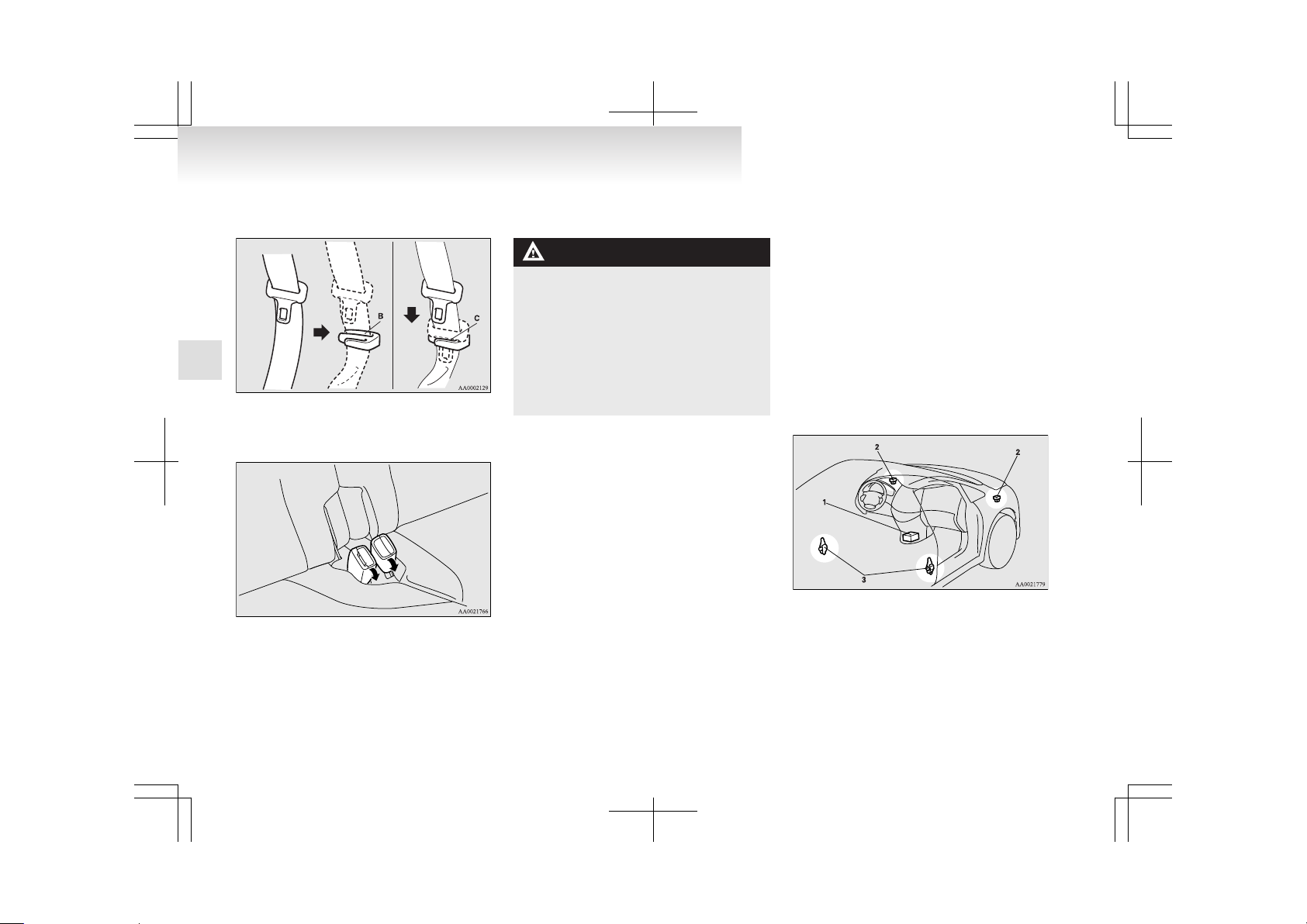
After passing the belt through the rear notch (B), insert the plate into the front notch (C).
Insert the third seat’s buckle into the pocket on the
seat cushion.
Pregnant women restraint
E00405600123
WARNING
l
Seat belts work for everyone, including
pregnant women. Pregnant women
should use the available seat belts. This
will reduce the likelihood of injury to
both the woman and the unborn child.
The lap belt should be worn across the
thighs and as snug against the hips as possible, but not across the waist. Consult
your doctor if you have any additional
questions or concerns.
Seat belt pretensioner system and
force limiter system
E00405700052
The driver’s seat and front passenger’s seat each
have a seat belt equipped with a pretensioner system.
Pretensioner system
E00405801034
The pretensioner system will retract their respective seat belts instantaneously, thus maximizing the
seat belt’s effectiveness, if there is a frontal impact
severe enough to injure the driver and/or front passenger and the ignition switch is in the “ON” or
“START” position.
The seat belt pretensioner includes the following
components:
1- Airbag control unit
2- Front impact sensors
3- Seat belt pretensioners
Seat and seat belts
2-20
2
Page 56
WARNING
l
To obtain the best results from your pretensioner seat belt, make sure you have adjusted your seat correctly and wear your
seat belt properly.
CAUTION
l
Installation of audio equipment or repairs in the vicinity of the pretensioner
seat belts or floor console must be performed in line with MITSUBISHI
MOTORS guidelines. It is important to
do so because the work could affect the
pretensioner systems.
l
If you need to scrap the vehicle, please consult a MITSUBISHI MOTORS Authorized Service Point. It is important to do
so because unexpected activation of the
pretensioner seat belts could cause injuries.
NOTE
l
The pretensioner seat belts will be activated
if the vehicle suffers a severe frontal impact,
even if the seat belts are not worn.
l
The pretensioner seat belts are designed to
work only once. After the pretensioner seat
belts have been activated, we recommend
you have it replaced by a MITSUBISHI
MOTORS Authorized Service Point.
SRS warning lamp
E00405900038
This warning lamp is shared by the SRS airbags
and the pretensioner seat belts. Refer to “SRS warning lamp” on page 2-42.
Force limiter system
E00406000023
In the event of a collision, each force limiter system will effectively absorb the load applied to the
seat belt to minimize the impact to the passenger.
Child restraint
E00406401532
When transporting children in your vehicle, some
type of child restraint system should always be
used according to the size of the child. This is required by law in most countries.
The regulations concerning driving with children in
the front seat may differ from country to country.
You are advised to comply with the relevant regulations.
WARNING
l
When possible, put children in the rear
seat. Accident statistics indicate that children of all sizes and ages are safer when
properly restrained in the rear seat rather than in the front seat.
l
Holding a child in your arms is no substitute for a restraint system. Failure to use
a proper restraint system can result in severe or fatal injury to your child.
l
Each child restraint device or fixing is to
be used only by one child.
l
When attaching a child restraint to the
rear seat, place the front seatbacks in the
upright position.
Otherwise, the child could be seriously injured in the event of hard braking or a collision.
Seat and seat belts
2-21
2
Page 57

Caution for installing the child restraint on vehicles with a front passenger airbag
The label shown here is attached on vehicles with a
front passenger airbag.
WARNING
l
Extreme Hazard!
Do not use a rearward facing child restraint on a seat protected by an airbag in
front of it!
l
A REARWARD FACING CHILD RESTRAINT must NOT be used in the front
passenger seat if the front passenger’s airbag has not been deactivated. The force
of an inflating airbag could kill or cause
serious injuries to the child. A rearward
facing child restraint should be used in
the rear seat.
Front passenger’s airbag ON
NOTE
l
If you have a rearward facing child restraint
system that cannot be fitted to any seat other
than the front passenger seat, be sure to turn
OFF the front passenger’s airbag ON-OFF
switch before using it. (Refer to “To turn an
airbag off” on page 2-33.)
Front passenger’s air bag OFF
WARNING
l
A FORWARD FACING CHILD RESTRAINT should be used in the rear seat
whenever possible; if used in the front
seat, adjust the seat to the most rearward
position.
Infants and small children
E00406600579
When transporting infants and small children in
your vehicle, follow the instructions given below.
Seat and seat belts
2-22
2
Page 58
Instructions:
l
For small infants, an infant carrier should be
used. For small children whose height when
seated allows the shoulder belt to lie in contact with the face or the throat, a child seat
should be used.
l
The child restraint system should be appropriate for your child’s weight and height and
properly fit in the vehicle. For a higher degree of safety: THE CHILD RESTRAINT
SYSTEM SHOULD BE INSTALLED IN
THE REAR SEAT.
WARNING
l
When installing a child restraint system,
refer to the instructions provided by the
manufacturer of the restraint system. Failure to do so can result in severe or fatal
injury to your child.
l
After installation, push and pull the child
restraint system back and forth, and side
to side, to see that it is properly secured.
If the child restraint system is not installed securely, it may cause injury to the
child or other occupants in the case of accident or sudden stops.
l
When the child restraint system is not in
use, keep your child or infant seat secured with the seat belt or remove it from
the vehicle in order to prevent injury to
your child.
NOTE
l
Before purchasing a child restraint system,
try installing it in the rear seat to make sure
there is a good fit. Because of the location of
the seat belt buckles and the shape of the seat
cushion, it may be difficult to securely install
some manufacturer’s child restraint systems.
If the child restraint system can be pulled forward or to either side easily on the seat cushion after the seat belt has been tightened,
choose another manufacturer’s child restraint
system.
Depending on the seating position in the vehicle and the child restraint system that you
have, the child restraint can be attached using one of the following 2 locations:
• To the lower anchorage in the rear seat,
ONLY if the child restraint has ISOFIX
mountings (See page 2-27).
• To the seat belt (See page 2-28).
Older children
E00406700192
Children who have outgrown the child restraint system should be seated in the rear seat and wear combination lap shoulder belt.
The lap portion of the belt should be snug and positioned low on the abdomen so that it is below the
top of the hip-bone. Otherwise, the belt could intrude into the child’s abdomen during an accident
and cause injury.
WARNING
l
Children who are not buckled up can be
thrown out of the vehicle in an accident.
l
Children who are not buckled up can
strike other people in the vehicle in an accident.
WARNING
l
A child should never be left unattended
in your vehicle. When you leave the vehicle, take the child with you.
Seat and seat belts
2-23
2
Page 59

Suitability for various seating positions
E00406800799
6 - person seat
Mass group
Seating position
Front passenger
Rear outboard
Intermediate Outboard
Activated airbag
Deactivated airbag*
1
Left side Right side
0 - Up to 10 kg (0-9 months) X X U U U
0+ - Up to 13 kg (0-2 years)
X
L*
2
U, L*
2
U, L*
2
U, L*
2
I - 9 to 18 kg (9 months - 4 years)
L*
3
L*
3
U, L*
3
U, L*
3
U, L*
3
II & III - 15 to 36 kg (4-12 years)
L*
4
L*
4
U, L*
4
U, L*
4
U, L*
4
*1: With front passenger’s airbag deactivated by means of front passenger’s airbag ON-OFF switch.
Key of letters to be inserted in the table above:
l
U- Suitable for “universal” category restraints approved for use in this mass group.
l
UF- Suitable for forward-facing “universal” category restraints approved for use in this mass group.
l
L- Suitable for particular child restraints (MITSUBISHI MOTORS genuine parts).
l
B- Built-in restraint approved for this mass group.
l
X- Seat position not suitable for children in this mass group.
L (Genuine part information)
Genuine parts No. ECE No.
*
2
MZ312807 E1-04301146
*
3
MZ312745 E1-04301136
MZ313045 E1-04301133
*
4
MZ312808 E1-04301148
Seat and seat belts
2-24
2
Page 60
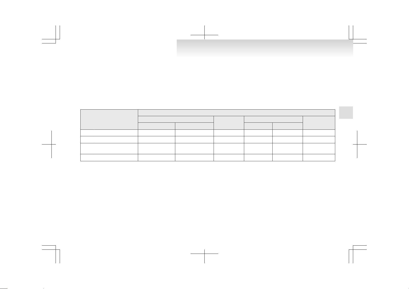
NOTE
l
The suitability table above applies to retention of child restraints using seat belts.
l
When MITSUBISHI MOTORS genuine part No. MZ313045 is used on the intermediate outboard seat, it can also be retained by means of ISOFIX child
restraint mountings.
l
There is no applicable MITSUBISHI MOTORS Genuine Parts to the Mass Group “0- Up to 10 kg (0-9 months)”.
MITSUBISHI MOTORS Europe B.V. reserves the right to changes without any prior announcement.
For further information, please contact your MITSUBISHI MOTORS Authorized Service Point.
7 - person seat
Mass group
Seating position
Front passenger
Rear outboard
Intermediate Outboard
Intermediate Cen-
tre
Activated airbag
Deactivated airbag*
1
Left side Right side
0 - Up to 10 kg (0-9 months) X X U U U X
0+ - Up to 13 kg (0-2 years)
X
L*
2
U, L*
2
U, L*
2
U, L*
2
L*
2
I - 9 to 18 kg (9 months - 4
years)
L*
3
L*
3
U, L*
3
U, L*
3
U, L*
3
L*
3
II & III - 15 to 36 kg (4-12 years)
L*
4
L*
4
U, L*
4
U, L*
4
U, L*
4
X
*1: With front passenger’s airbag deactivated by means of front passenger’s airbag ON-OFF switch.
Key of letters to be inserted in the table above:
l
U- Suitable for “universal” category restraints approved for use in this mass group.
l
UF- Suitable for forward-facing “universal” category restraints approved for use in this mass group.
l
L- Suitable for particular child restraints (MITSUBISHI MOTORS genuine parts).
l
B- Built-in restraint approved for this mass group.
l
X- Seat position not suitable for children in this mass group.
Seat and seat belts
2-25
2
Page 61

L (Genuine part information)
Genuine parts No. ECE No.
*
2
MZ312807 E1-04301146
*
3
MZ312745 E1-04301136
MZ313045 E1-04301133
*
4
MZ312808 E1-04301148
NOTE
l
The suitability table above applies to retention of child restraints using seat belts.
l
When MITSUBISHI MOTORS genuine part No. MZ313045 is used on the intermediate outboard seat, it can also be retained by means of ISOFIX child
restraint mountings.
l
There is no applicable MITSUBISHI MOTORS Genuine Parts to the Mass Group “0- Up to 10 kg (0-9 months)”.
MITSUBISHI MOTORS Europe B.V. reserves the right to changes without any prior announcement.
For further information, please contact your MITSUBISHI MOTORS Authorized Service Point.
Seat and seat belts
2-26
2
Page 62
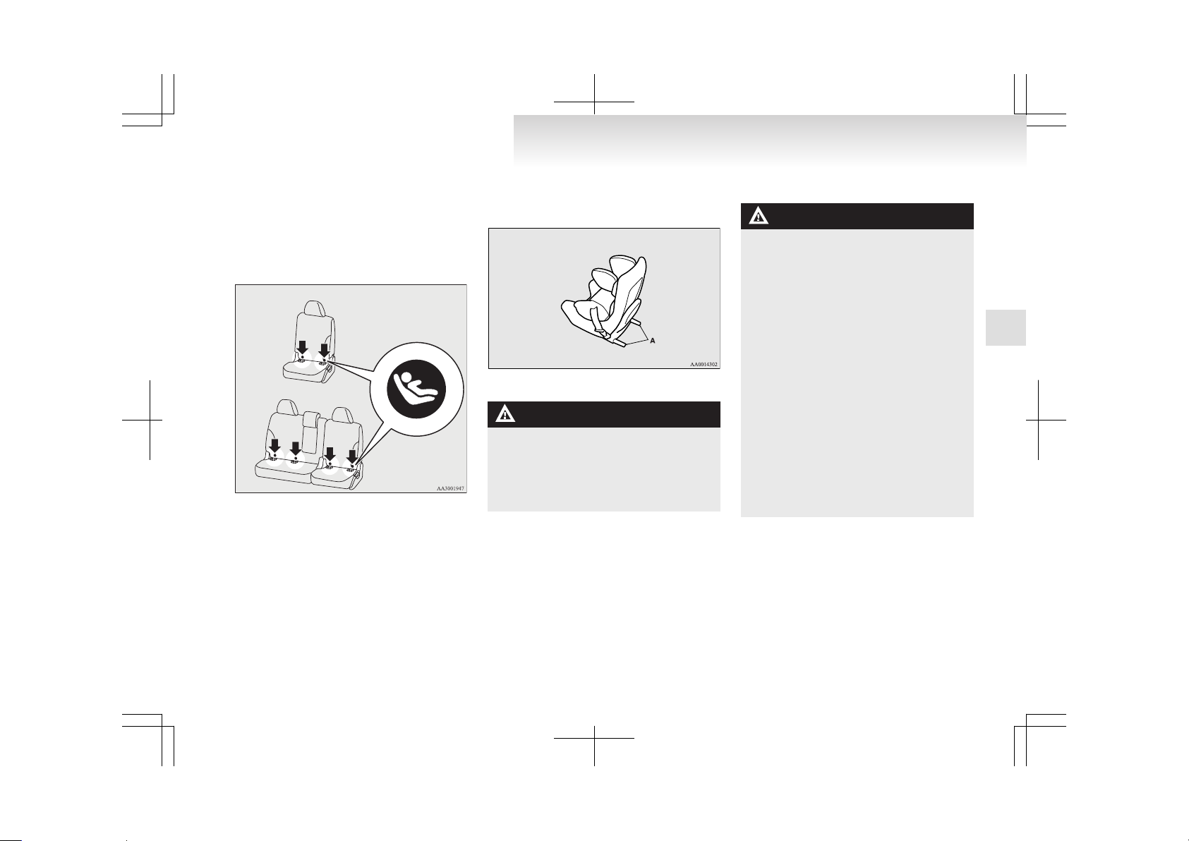
Installing a child restraint system to
the lower anchorage (ISOFIX child restraint mountings)
E00408900042
Your vehicle’s second seat is fitted with lower anchorages for attaching a child restraint system with
ISOFIX mountings.
6-person seat
7-person seat
Child restraint system with ISOFIX mountings
E00409000532
The child restraint system is designed only for
seats that incorporate lower anchorages. Retain the
child restraint system using the lower anchorages.
It is not necessary to retain the child restraint system using the vehicle’s seat belts. Only a
MITSUBISHI MOTORS genuine child restraint
system can be used.
Genuine parts No.: MZ313045
ECE No.: E1-04301133
A: Child restraint system connectors
WARNING
l
If a child restraint system other than a
MITSUBISHI MOTORS genuine one is
used, it may not be properly retained and
the child could be seriously injured as a
result. Use only a MITSUBISHI
MOTORS genuine child restraint system.
To install
WARNING
l
If there is any foreign material in or
around the connectors, remove it before
installing the child restraint system. Also,
make sure the seat belt is away from, not
looped through or otherwise interfering
with, the child restraint system. If foreign
matter is not removed and/or the seat
belt interferes with the child restraint system, the child restraint system will not be
secured properly and could move forward in the event of sudden braking or a
collision, seriously injuring the child and
possibly other vehicle occupants.
l
Use the top tether strap when fitting a
child restraint system with ISOFIX
mountings.
Otherwise, the child could be seriously injured in the event of hard braking or a collision.
l
When the vehicle is moving do not adjust
the seat where the child restraint system
is installed.
1. Slide the second seats to the fully backward
position. (Refer to “To adjust forward or backward” on page 2-07.)
Seat and seat belts
2-27
2
Page 63
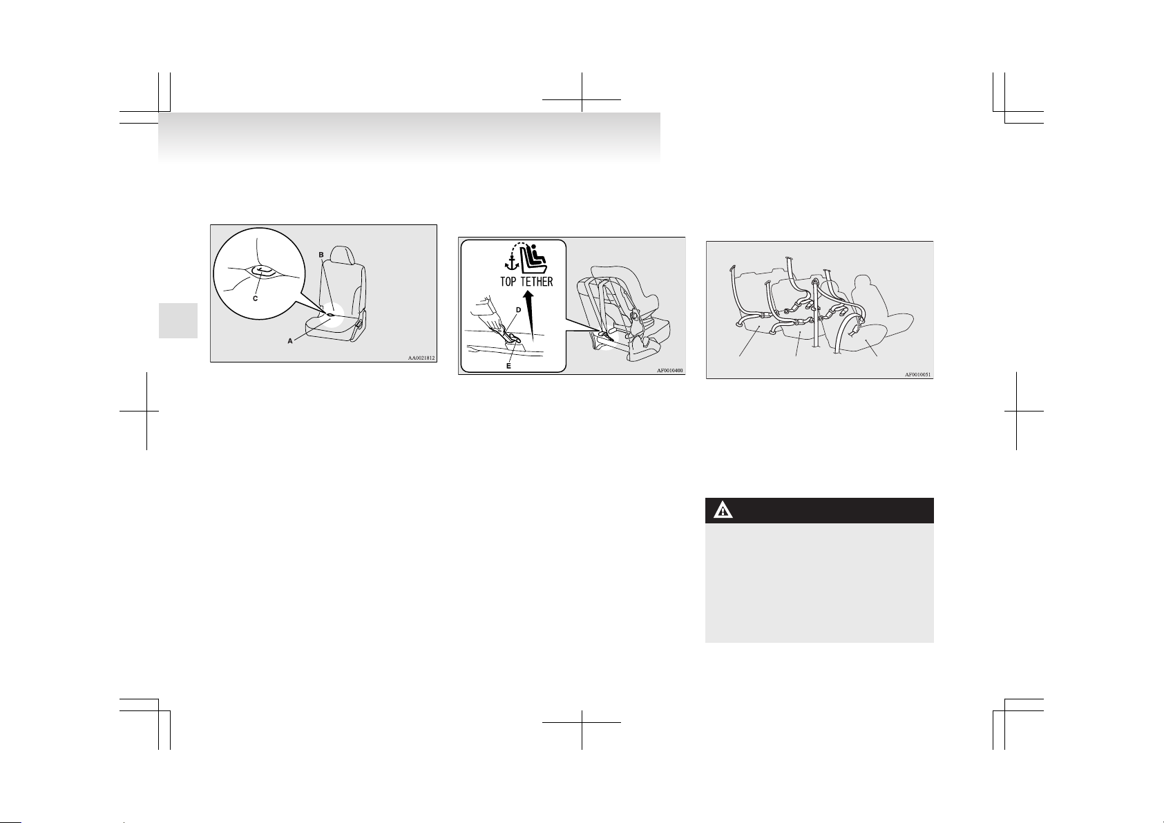
2. Open the gap a little between the seat cushion (A) and the seatback (B) with your hand
to locate the lower anchorages (C).
3. Push the child restraint system’s connectors
into the lower anchorages (C) in accordance
with the instructions provided by the child restraint system’s manufacturer.
4. Remove the head restraint from the location
in which you wish to install a child restraint.
5. Latch the tether strap hook (D) of the child
seat to the tether anchorage (E) and tighten
the top tether strap hook so it is securely fastened.
6. Push and pull the child restraint system in all
directions to be sure it is firmly secured.
To remove
Remove the child restraint in accordance with the
instructions provided by the child restraint system’s manufacturer.
Installing a child restraint system to a 3-point type seat belt (with emergency locking mechanism)
E00408700545
Third seat Second seat Front passenger seat
Installation:
1. Fasten the seat belt to secure the child restraint system. Make sure you hear a “click”
when you insert the latch plate in the buckle.
2. Remove all slack by using the locking clip.
3. Push and pull the child restraint in all directions to be sure it is secure.
WARNING
l
For some types of child restraint, the locking clip (A) should be used to help avoid
personal injury during a collision or sudden manoeuvre.
It must be fitted and used in accordance
with the child restraint manufacturer’s instructions.
The locking clip must be removed when
the child restraint is removed.
Seat and seat belts
2-28
2
Page 64
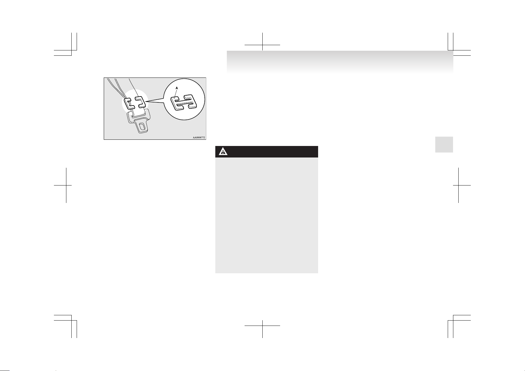
Seat belt inspection
E00406300550
l
Check the belts for cuts, worn or frayed webbing and for cracked or deformed metallic
parts. Replace the belt assembly if it is defective.
l
A dirty belt should be cleaned with neutral detergent in warm water. After rinsing in water,
let it dry in the shade. Do not attempt to
bleach or re-dye the belts because this will affect their characteristics.
WARNING
l
We recommend you have all seat belt assemblies including retractors and attaching hardware inspected after any collision. We recommend that seat belt assemblies in use during a collision be replaced
unless the collision was minor and the
belts show no damage and continue to operate properly.
l
Do not attempt to repair or replace any
part of the seat belt assemblies; we recommend you have this work done by a
MITSUBISHI MOTORS Authorized
Service Point. Incorrect repair or replacement could reduce the effectiveness of the
belts and could result in serious injury in
the event of a collision.
l
Once the pretensioner has been activated,
it cannot be re-used.
It must be replaced together with the retractor.
Supplemental restraint system
(SRS) - airbag
E00407201742
The information written in this Supplemental Restraint System (SRS) section contains important
points concerning the driver, front passenger, driver’s knee, side and curtain airbags.
The SRS driver and front passenger airbags are designed to supplement the primary protection of the
driver and front passenger side seat belt systems by
providing those occupants with protection against
head and chest injuries in certain moderate-to-severe frontal collisions.
The SRS driver and front passenger airbags employ a dual stage airbag system. The SRS driver
and front passenger airbag is controlled by the impact sensors (at the front of the vehicle and near the
center of the vehicle at floor level) and the driver’s
seat position sensor and the SRS front passenger airbag is controlled by the impact sensors.
The SRS side airbags are designed to supplement
properly worn seat belts and provide the driver and
front passenger with protection against chest and abdomen injuries in certain moderate-to-severe side
impact collisions.
The SRS curtain airbags are designed to supplement properly worn seat belts and provide the driver and passenger with protection against head injuries in certain moderate-to-severe side impact collisions.
Seat and seat belts
2-29
2
Page 65

The SRS is NOT a substitute for the seat belts; for
maximum protection in all types of crashes and accidents, seat belts should ALWAYS be worn by everyone who drives or rides in this vehicle. (With infants and small children in child restraints and older children buckled in the rear seat.)
WARNING
l
IT IS VERY IMPORTANT TO ALWAYS PROPERLY WEAR YOUR
SEAT BELT, EVEN WITH AN AIRBAG:
• Seat belts help keep the driver and passenger properly positioned, which reduces injury risk in all collisions, and
reduces the risk of serious or fatal injuries when the airbags inflate.
During sudden braking just before a
collision, an unrestrained or improperly restrained driver or passenger can
move forward into direct contact with
or within close proximity to the airbag
which may then deploy during the collision.
The initial stage of airbag inflation is
the most forceful which could cause serious or fatal injuries if the occupant
contacts it at this stage.
• Seat belts reduce the risk of injury in
roll-overs, rear impact collisions, and
in lower-speed frontal collisions, because driver’s and passenger’s airbags are not designed to inflate in
those situations.
• Seat belts reduce the risk of being
thrown from your vehicle in a collision or roll-over.
WARNING
l
IT IS VERY IMPORTANT TO BE PROPERLY SEATED.
A driver or front passenger too close to
the steering wheel or instrument panel
during airbag deployment can be killed
or seriously injured.
Airbags inflate very fast, and with great
force.
If the driver and front passenger are not
properly seated and restrained, the airbags may not protect you properly, and
could cause serious or fatal injuries when
it inflates.
• Before driving, adjust the driver’s
seat as far back as possible while still
maintaining complete control of the vehicle.
• Before driving, adjust the front passenger seat as far back as possible.
• Make sure all vehicle occupants are always properly restrained using the
available seat belts.
• With seat belts properly fastened, the
driver and passenger should sit well
back and upright without leaning
against the window or door.
l
Do not sit on the edge of the seat, or lean
head or chest close to the steering wheel
or instrument panel.
Do not put feet or legs on or against the
instrument panel.
WARNING
l
Place all infants and small children in the
rear seat and properly restrained using
an appropriate child restraint system.
The rear seat is the safest place for infants and children.
WARNING
l
Infants and small children should never
be unrestrained, stand up against the instrument panel or be held in your arms
or on your lap. They could be seriously injured or killed in a collision, including
when the airbag inflates. They should be
properly seated in the rear seat in an appropriate child restraint system. See the
“Child restraint” section in this owner’s
manual.
Seat and seat belts
2-30
2
Page 66
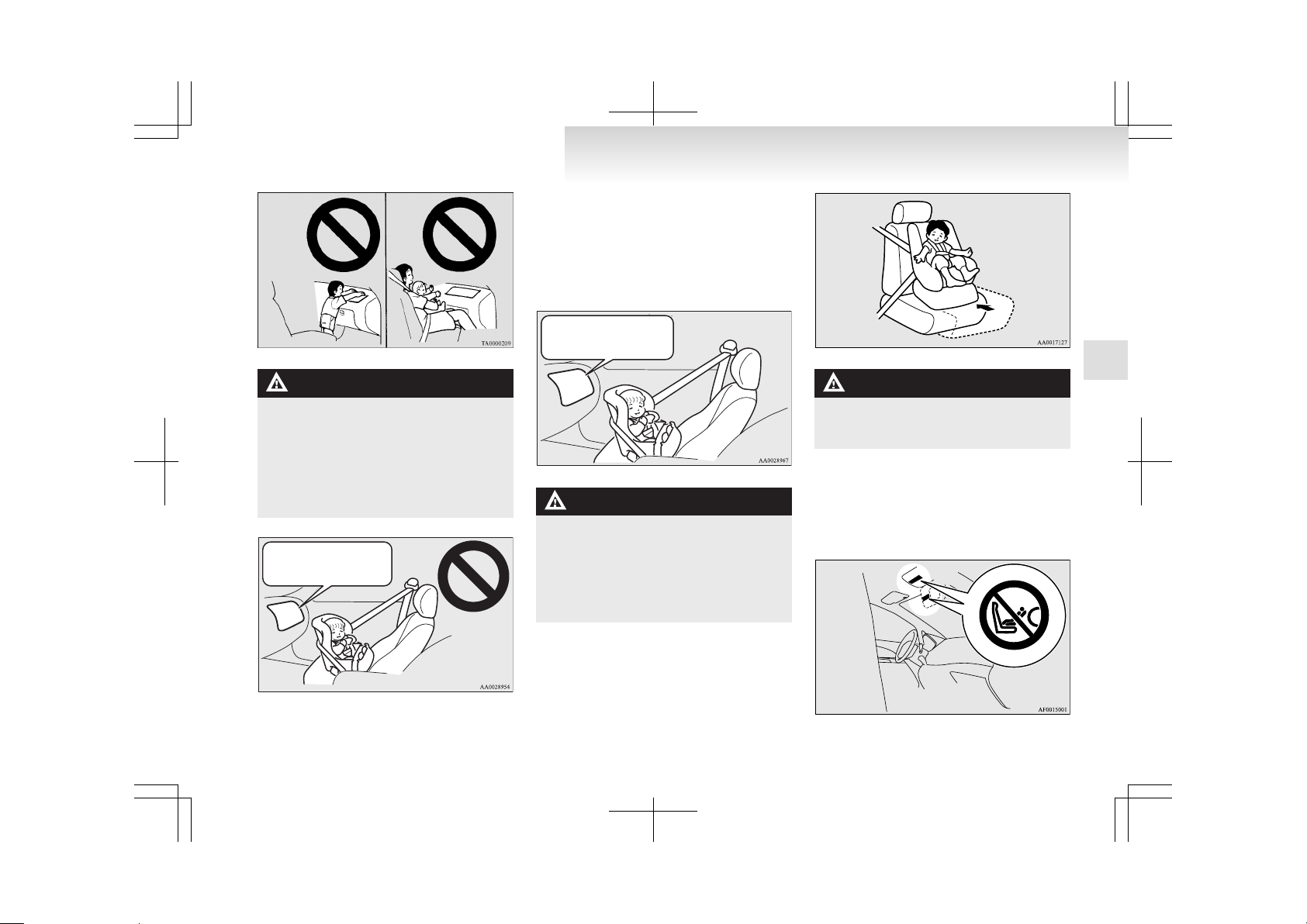
WARNING
l
A REARWARD FACING CHILD RESTRAINT must NOT be used in the front
passenger seat if the front passenger’s airbag has not been deactivated. The force
of an inflating airbag could kill or cause
serious injuries to the child. A rearward
facing child restraint should be used in
the rear seat.
Front passenger’s airbag ON
NOTE
l
If you have a rearward facing child restraint
system that cannot be fitted to any seat other
than the front passenger seat, be sure to turn
OFF the front passenger’s airbag ON-OFF
switch before using it. (Refer to “To turn an
airbag off” on page 2-33.)
Front passenger’s air bag OFF
WARNING
l
A FORWARD FACING CHILD RESTRAINT should be used in the rear seat
whenever possible; if it must be used in
the front passenger seat, adjust the seat
to the most rearward position. Failure to
do so could kill or cause serious injuries
to the child.
WARNING
l
Older children should be seated in the
rear seat, properly wearing the seat belt,
with an appropriate booster seat if needed.
Caution for installing the child restraint on vehicles with a front passenger airbag
The label shown here is attached on vehicles with a
front passenger airbag.
Seat and seat belts
2-31
2
Page 67

WARNING
l
Extreme Hazard!
Do not use a rearward facing child restraint on a seat protected by an airbag in
front of it!
How the Supplemental Restraint System works
E00407300935
The SRS includes the following components:
1. Airbag module (Driver)
2. Front passenger’s airbag OFF indication lamp
3. Airbag module (Passenger)
4. Front impact sensors
5. Driver’s seat position sensor
6. Airbag control unit
7. Front passenger’s airbag ON-OFF switch
8. Side airbag modules
9. Curtain airbag modules
10. Side impact sensors
The airbags will operate only when the ignition
switch is in the “ON” or “START” position.
When the impact sensors detect an impact of sufficient frontal or side force, an automated circuit ignites materials in the inflator to generate gas and inflate the airbags.
The airbags deployment produces a sudden, loud
noise, and releases some smoke and powder, but
these conditions are not injurious, and do not indicate a fire in the vehicle. People with respiratory
problems may feel some temporary irritation from
chemicals used to produce the deployment; open
the windows after airbag deployment, if safe to do
so.
The airbags deflate very rapidly after deployment,
so there is little danger of obscured vision.
The time required from the sensors detecting an impact to deflation of the airbags after deployment is
shorter than a blink of an eye.
CAUTION
l
Airbags inflate at an extremely rapid
speed. In certain situations, contact with
inflating airbags can result in abrasions,
light cuts, bruises, and the like.
Driver’s seat position sensor
E00409900166
In order to detect the fore-aft position of the driver’s seat, the driver’s seat position sensor is attached to the seat rail.
In the event of a problem in the driver’s seat position sensor, the SRS warning lamp comes on.
Seat and seat belts
2-32
2
Page 68
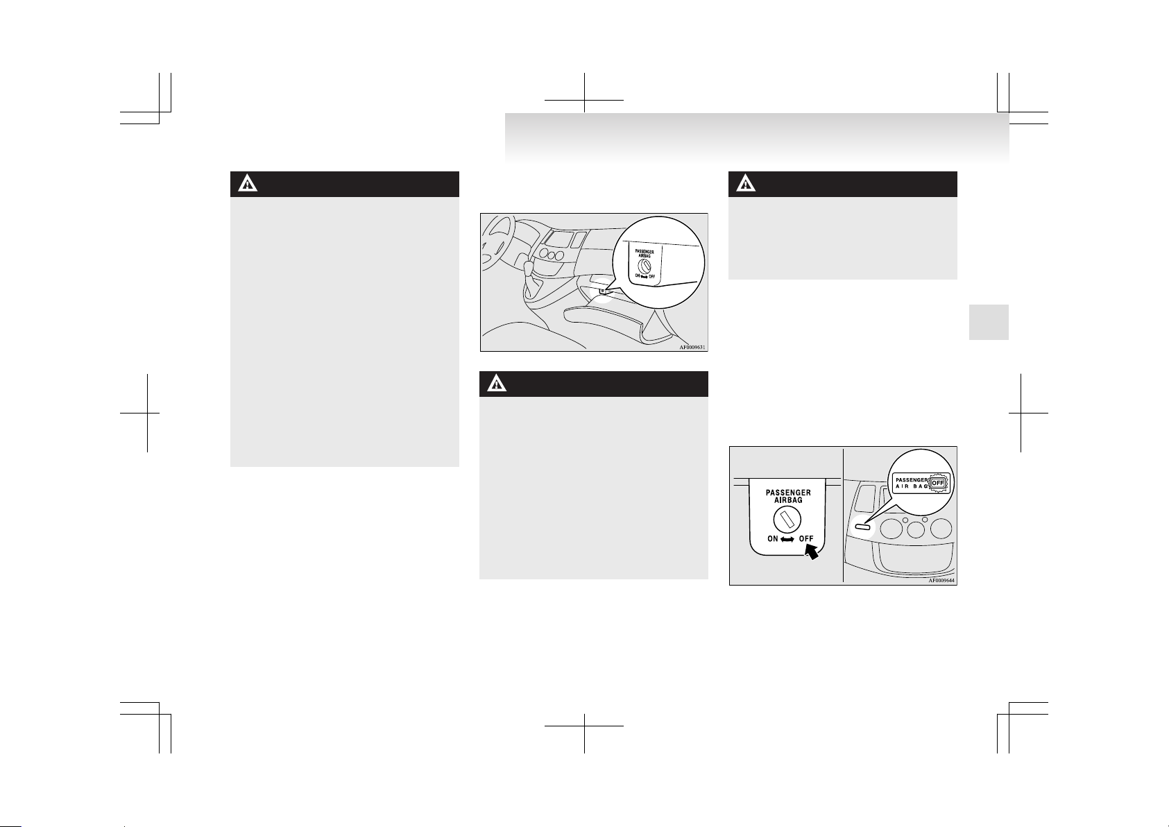
WARNING
l
If the SRS warning lamp comes on, we recommend you to have the vehicle inspected by a MITSUBISHI MOTORS Authorized Service Point as soon as possible.
l
Please observe the following instructions
to ensure that the driver’s seat position
sensor can sense the seat position correctly. Otherwise, the dual stage airbags may
not operate correctly.
• Adjust the seat to the correct position,
and sit correctly with your back
against the seatback.
Refer to “Front seat” on page 2-05.
• Do not have the seatback reclined
more than necessary when driving.
• Do not place metallic objects or luggage under the seat.
l
If the vehicle suffers a severe impact, we
recommend you to have the sensor inspected by a MITSUBISHI MOTORS Authorized Service Point as soon as possible.
Front passenger’s airbag ON-OFF switch
E00410100214
The front passenger’s airbag ON-OFF switch can
be used to disable the front passenger’s airbag. If
you have a rearward facing child restraint system
that cannot be fitted to any seat other than the front
passenger seat, be sure to turn OFF the front passenger’s airbag ON-OFF switch before using it. (Refer
to “To turn an airbag off” on page 2-33.)
The front passenger’s airbag ON-OFF switch is located in the glove box.
WARNING
l
To reduce risk of serious or fatal injury:
• Always remove the key from the ignition switch before operating a front
passenger’s airbag ON-OFF switch.
Failure to do so could adversely affect
the airbag performance.
• Wait at least 60 seconds to operate the
front passenger’s airbag ON-OFF
switch after turning the ignition
switch from “ON” position to
“LOCK” position.
The SRS airbag system is designed to
retain enough voltage to deploy the airbag.
WARNING
• Always remove the key from the front
passenger’s airbag ON-OFF switch after operating that switch. Failure to
do so could lead to improper position
of the front passenger’s airbag
ON-OFF switch.
To turn an airbag off
E00410600251
To turn an airbag off, follow these steps:
1. Insert the key into the key opening of the appropriate front passenger’s airbag ON-OFF
switch, and turn that airbag ON-OFF switch
to the “OFF” position.
2. Remove the key from the key opening of that
front passenger’s airbag ON-OFF switch.
3. Insert the key into the ignition switch, and
turn the ignition to the “ON” position.
Seat and seat belts
2-33
2
Page 69
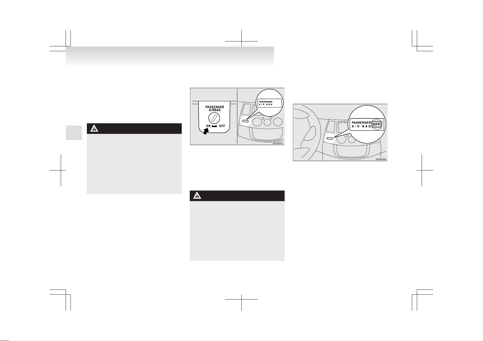
That airbag OFF indication lamp, with the word
“OFF” (depending upon which airbag has been
turned off) should illuminate. That will tell you
that airbag is OFF, and will NOT deploy. (Refer to
“Front passenger’s airbag OFF indication lamp” on
page 2-34.)
That airbag will remain OFF, and will NOT deploy, until it is turned ON again.
WARNING
l
To reduce risk of serious or fatal injury:
• If the indication lamp does not come
on when the front passenger’s airbag
ON-OFF switch is turned OFF, do not
fit a rearward facing child restraint
system to the front passenger seat.
• Do not turn OFF the front passenger’s airbag ON-OFF switch except
when a rearward facing child restraint system is fitted to the front passenger seat.
To turn an airbag on
E00410700122
To turn an airbag on, follow these steps:
1. Insert the key into the key opening of the appropriate front passenger’s airbag ON-OFF
switch, and turn that airbag ON-OFF switch
to “ON” position.
2. Remove the key from the key opening of that
front passenger’s airbag ON-OFF switch.
3. Insert the key into the ignition switch, and
turn the ignition to the “ON” position.
That airbag OFF indication lamp, with the word
“OFF” (depending upon which airbag has been
turned back on) should not illuminate.
That airbag will remain ON, and will be ready to
deploy, until it is again turned OFF.
WARNING
l
To reduce risk of serious or fatal injury:
• Turn ON the front passenger’s airbag
ON-OFF switch immediately after removing a rearward facing child restraint system from the front passenger seat.
• If the indication lamp remains on
when the front passenger’s airbag
ON-OFF switch is turned ON, do not
allow anyone to sit on the front passenger seat.
Front passenger’s airbag OFF indication lamp
E00410200228
The front passenger’s airbag OFF indication lamp
is located in the instrument panel.
The indication lamp normally comes on when the
ignition switch is turned to the “ON” position, and
goes off a few seconds later. When the front passenger’s airbag ON-OFF switch is turned OFF, the indication lamp will stay on to show that the front passenger’s airbag is not operational.
When the front passenger’s airbag ON-OFF switch
is turned ON, the indication lamp goes off to show
that the front passenger’s airbag is operational.
Seat and seat belts
2-34
2
Page 70
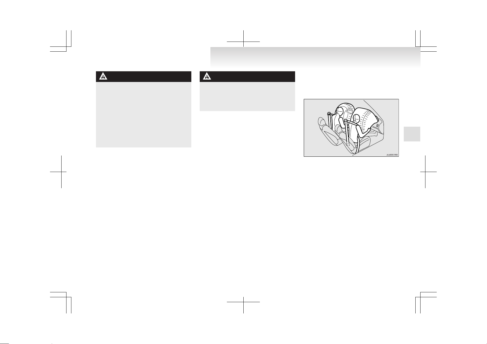
WARNING
l
If the indication lamp behaves in any of
the following ways, there may be a fault
in the airbag system. We recommend you
to have the vehicle inspected by a
MITSUBISHI MOTORS Authorized
Service Point as soon as possible.
• The indication lamp does not come on
when the front passenger’s airbag
ON-OFF switch is turned OFF.
• The indication lamp stays on when the
front passenger’s airbag ON-OFF
switch is turned ON.
WARNING
l
Do not fit any accessory that makes the indication lamp impossible to see, and do
not cover the indication lamp with a sticker. You would not be able to verify the status of the passenger airbag system.
Driver’s and passenger’s front airbag system
E00407400356
The driver’s airbag is located under the padded cover in the middle of the steering wheel. The front passenger’s airbag is contained in the instrument panel
above the glove box.
The driver’s airbag inflates at two different rates according to the fore-aft position of the driver’s seat
and the severity of the impact.
The front passenger’s airbag deploys at the same
time as the driver’s airbag, even if the passenger
seat is not occupied, and inflates at two different
rates according to the severity of the impact.
Deployment of front airbags
E00407501442
The front airbags ARE DESIGNED TO DEPLOY when…
Seat and seat belts
2-35
2
Page 71

Head-on collision with a solid wall at speed of
approximately 25 km/h (16 mph) or higher
Moderate to severe frontal impact within the shaded
area between the arrows
The front airbags are designed to deploy when the
vehicle suffers a moderate to severe frontal impact.
A typical condition is shown in the illustration.
The front airbags will deploy if the severity of impact is above the designed threshold level, comparable to an approximately 25 km/h (16 mph) collision when impacting straight into a solid wall that
does not move or deform. If the severity of the impact is below the above threshold level, the front airbags may not deploy. However, this threshold
speed will be considerably higher if the vehicle
strikes an object that absorbs the impact by either
deforming or moving (for example, another stationary vehicle, pole or a guard rail).
Because frontal collisions can easily move you out
of position, it is important to always properly wear
your seat belts. Your seat belts will help keep you
in a safe distance from the steering wheel and instrument panel during the initial stages of airbag deployment. The initial stage of airbag inflation is the
most forceful, and can possibly cause serious or fatal injuries. Moreover, the seat belts in your vehicle
are your primary means of protection in a collision.
The SRS airbags are designed to provide additional
protection. Therefore, for your safety and the safety of all occupants, be sure to always properly wear
your seat belts.
The front airbags MAY NOT DEPLOY when…
With certain types of frontal collisions, the vehicle’s body structure is designed to absorb the shock
to help protect the occupants from harm. (The vehicle body’s front area may deform significantly as it
absorbs the impact.) Under such circumstances, the
front airbags may not deploy irrespective of the deformation and damage to the vehicle body.
Examples of some typical conditions are shown in
the illustration.
Seat and seat belts
2-36
2
Page 72
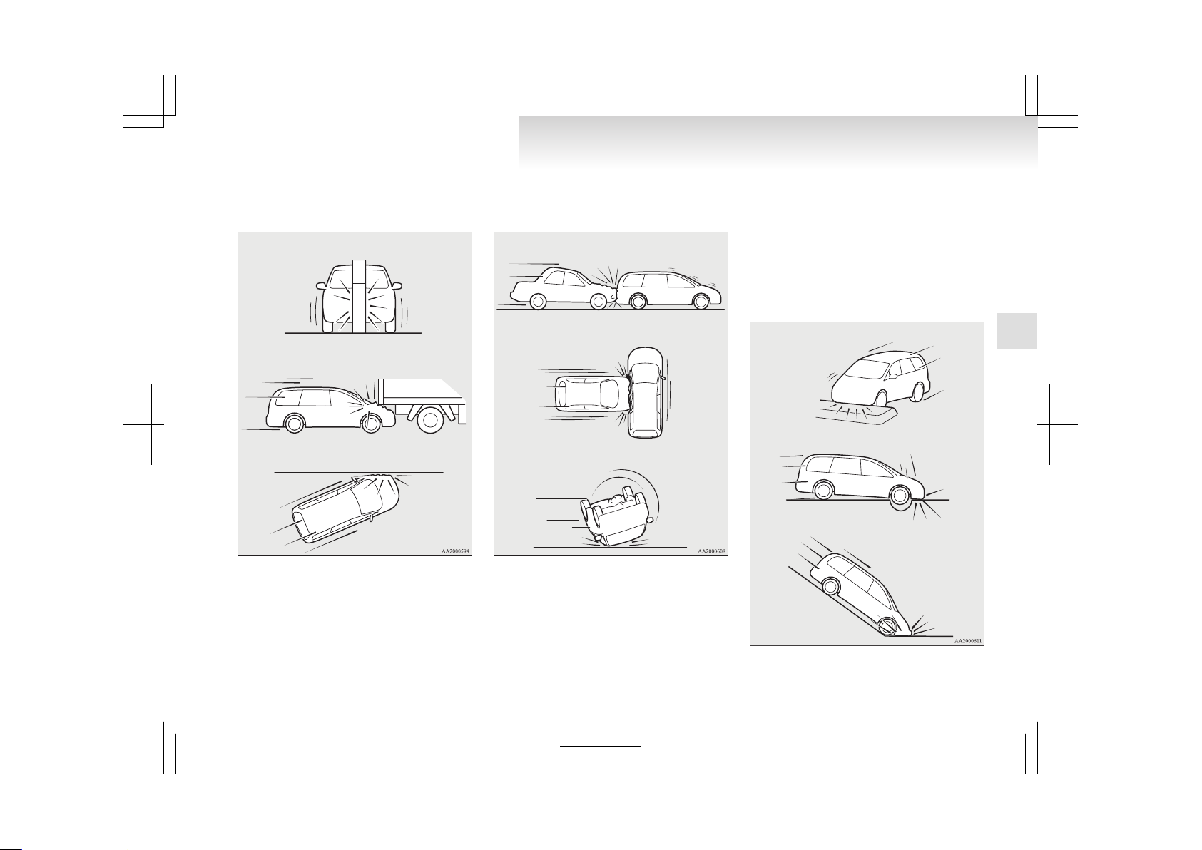
Because the front airbags do not protect the occupant in all types of frontal collisions, be sure to always properly wear your seat belts.
Collision with a utility pole, tree or other narrow objects
Vehicle slides under the rear body of a truck
Oblique frontal impacts
The front airbags ARE NOT DESIGNED TO DEPLOY when…
The front airbags are not designed to deploy in conditions where they cannot typically provide protection to the occupant. Such conditions are shown in
the illustration.
Because the front airbags do not protect the occupant in all types of collisions, be sure to always properly wear your seat belts.
Rear end collisions
Side collisions
Vehicle rolls onto its side or roof
The front airbags MAY DEPLOY when…
The front airbags may deploy if the bottom of the
vehicle suffers a moderate to severe impact (undercarriage damage).
Examples of some typical conditions are shown in
the illustration.
Because the front airbags may deploy in certain
types of unexpected impacts as shown in the illustration that can easily move you out of position, it
is important to always properly wear your seat
belts. Your seat belts will help keep you a safe distance from the steering wheel and instrument panel
during the initial stages of airbag deployment. The
initial stage of airbag inflation is the most forceful
and can possibly cause serious or fatal injuries if
you contact it at this stage.
Collision with an elevated median/island or kerb
Vehicle travels over a deep hole/pothole
Vehicle drives down a steep slope and hits the ground
Seat and seat belts
2-37
2
Page 73

WARNING
l
Do not attach anything to the steering
wheel padded cover, such as trim material, badges, etc. It might strike and injure
an occupant if the airbag inflates.
l
Do not set anything on, or attach anything to, the instrument panel above the
glove box. It might strike and injure an occupant if the airbag inflates.
WARNING
l
Do not attach accessories to, or put them
in front of, the windscreen. These objects
could restrict the airbag inflation, or
strike and injure an occupant if the airbags inflate.
l
Do not put packages, pets or other objects between the airbags and the driver
or front passenger. It could affect airbag
performance, or could cause injury when
the airbag inflates.
WARNING
l
Right after the airbag inflation, several
airbag system components will be hot. Do
not touch them; you could be burned.
l
The airbag system is designed to work only once. Once the airbags have deployed,
they will not work again. They must
promptly be replaced, and we recommend you to have the entire airbag system inspected by a MITSUBISHI
MOTORS Authorized Service Point.
Side airbag system
E00407600055
The side airbags (A) are contained in the driver and
front passenger seatbacks.
The side airbag is designed to inflate only on the
side of the vehicle that is impacted, even with no
passenger in the front seat.
The label shown here is attached to the seatbacks
with a side airbag.
Curtain airbag system
E00409100038
The curtain airbags are contained in the front pillars and roof side rail. The curtain airbag is designed to inflate only on the side of the vehicle that
is impacted, even with no passenger in the front
seat or second seat.
Seat and seat belts
2-38
2
Page 74

Deployment of side airbags and curtain airbags
E00407701082
The side airbags and curtain airbags ARE DESIGNED TO DEPLOY when…
The side airbags and curtain airbags are designed
to deploy when the vehicle suffers a moderate to severe side impact to the middle of the passenger compartment.
The typical condition is shown in the illustration.
The seat belts in your vehicle are your primary
means of protection in a collision. The SRS side airbags and curtain airbags are designed to provide additional protection. Therefore, for your safety and
the safety of all occupants, be sure to always properly wear your seat belts.
The side airbags and curtain airbags MAY NOT DEPLOY when…
With certain types of side collisions, the vehicle’s
body structure is designed to absorb the shock to
help protect the occupants from harm. (The vehicle
body’s side area may deform significantly as it absorbs the impact.) Under such circumstances, the
side airbags and curtain airbags may not deploy irrespective of the deformation and damage to the vehicle body. Also, depending on the location of the
impact, the side airbags and curtain airbags may
not deploy simultaneously.
Examples of some typical conditions are shown in
the illustration.
Because the side airbags and curtain airbags do not
protect the occupant in all types of side collisions,
be sure to always properly wear your seat belts.
Side impacts in an area away from the passenger
compartment
Motorcycle or other similar small vehicle collides with the
side of vehicle
Collision with a utility pole, tree or other narrow object
Seat and seat belts
2-39
2
Page 75

Oblique side impacts
Vehicle rolls onto its side or roof
The side airbags and curtain airbags ARE NOT DESIGNED TO DEPLOY when…
The side airbags and curtain airbags are not designed to deploy in conditions where they cannot
usually provide protection to the occupant. Typical
conditions are shown in the illustration.
Head-on collisions
Rear end collisions
Because the side airbags and curtain airbags do not
protect the occupant in all types of collisions, be
sure to always properly wear your seat belts.
WARNING
l
The side airbags and curtain airbags are
designed to supplement the driver and passenger seat belts in certain side impacts.
Seat belts should always be worn properly, and the driver and passenger should
sit well back and upright without leaning
against the window or door.
WARNING
l
The side airbag and curtain airbag inflate
with great force. The driver and passenger should not put their arms out of the
window, and should not lean against the
door, in order to reduce the risk of serious or possible fatal injury from the deploying side airbag and curtain airbag.
WARNING
l
Do not allow a child to kneel on the passenger seat facing the passenger’s side
door, since the side airbags and curtain
airbags inflate with great force.
Otherwise, the child may be killed or seriously injured.
Seat and seat belts
2-40
2
Page 76
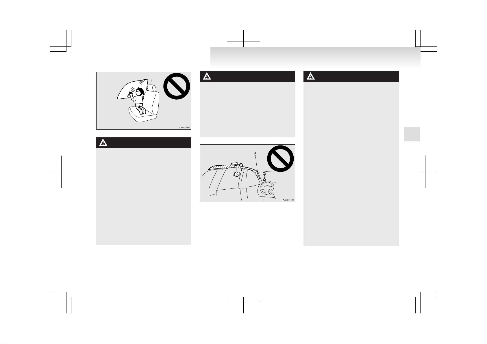
WARNING
l
Do not allow any second seat occupant to
hold onto the seatback of either front
seat, in order to reduce risk of injury
from the deploying side airbags. Special
care should be taken with children.
l
Do not place any objects near or in front
of the seatback of either front seat. They
could interfere with proper side airbag inflation, and also could cause injury if
thrown free by side airbag deployment.
l
Do not place stickers, labels or additional
trim on the seatback of either front seat.
They could interfere with proper side airbag inflation.
l
Do not install seat covers on seats with
side airbags. Do not re-cover the seats
with side airbags. They could interfere
with proper side airbag inflation.
WARNING
l
Do not attach a microphone (A) or any
other device or object around the part
where the curtain airbags activate such
as on the windscreen, side door glass,
front and rear pillars and roof side or assist grips. When the curtain airbags inflate, the microphone or other device or
object will be hurled with great force or
the curtain airbags may not activate correctly, resulting in death or serious injury.
WARNING
l
Do not put a hanger or any heavy or pointed object on the coat hook.
If the curtain airbag was activated, any
such item could be propelled away with
great force and could prevent the curtain
airbag from inflating correctly. Hang
clothes directly on the coat hook (without
using a hanger).
Make sure there are no heavy or sharp objects in the pockets of clothes that you
hang on the coat hook.
l
Do not allow a child to lean against or
close to the front door even if the child is
seated in a child restraint system.
The child’s head should also not be
leaned against or be close to the area
where the side airbags and curtain airbags are located. It is dangerous if the
side airbags and curtain airbags inflate.
Failure to follow all of these instructions
could lead to serious or fatal injury to the
child.
l
We recommend work around and on the
side airbags and curtain airbags system
to be done by a MITSUBISHI MOTORS
Authorized Service Point. Improper
work could result in inadvertent deployment of side airbags and curtain airbags,
or could render side airbags and curtain
airbags inoperative; either situation
could result in serious injury.
Seat and seat belts
2-41
2
Page 77

SRS warning lamp
E00407800653
There is a Supplemental Restraint System (“SRS”)
warning lamp on the instrument panel. The system
checks itself and the lamp tells you if there is a problem. When the ignition switch is turned to the
“ON” or “START” position, the warning lamp
should illuminate for several seconds and then
should go out. This means the system is ready. If
an SRS airbag or pretensioner seat belt is not operating properly, the warning lamp comes on and
stays on.
The SRS warning lamp is shared by the following:
l
Driver’s airbag
l
Front passenger’s airbag
l
Side airbags
l
Curtain airbags
l
Seat belt pretensioners
l
Driver’s seat position sensor
l
Front passenger’s airbag ON-OFF switch
WARNING
l
If any of the following conditions occur,
the SRS and/or seat belt pretensioners
are not working properly, and we recommend you to have it inspected by a
MITSUBISHI MOTORS Authorized
Service Point immediately.
• The SRS warning lamp does not illuminate when you start the vehicle.
• The SRS warning lamp does not go
out after several seconds.
• The SRS warning lamp illuminates
while driving.
SRS servicing
E00407900726
WARNING
l
We recommend any maintenance performed on or near the components of the
SRS to be performed by a MITSUBISHI
MOTORS Authorized Service Point.
Improper work on the SRS components
or wiring could result in inadvertent deployment of the airbags, or could render
the SRS inoperative; either situation
could result in serious injury.
l
Do not modify your steering wheel, seat
belt retractor or any other SRS components. For example, replacement of the
steering wheel, or modifications to the
front bumper or body structure can adversely affect SRS performance and lead
to possible injury.
WARNING
l
If your vehicle has sustained any damage,
we recommend you to have the SRS inspected to ensure it is in proper working
order.
l
Do not modify your front seats, centre pillar and centre console.
It can adversely affect SRS performance
and lead to possible injury.
Also, if you have found any tear or open
seam in the seat fabric at the portion near
the side airbag, we recommend you to
have the seat inspected.
l
If you have found any scratch, crack or
damage to the portion of the front and
rear pillars and roof side rail, you should
have the SRS inspected by a
MITSUBISHI MOTORS Authorized
Service Point.
NOTE
l
When you transfer ownership of the vehicle
to some other person, we urge you to alert
the new owner that it is equipped with the
SRS and refer the new owner to the applicable section in this owner’s manual.
l
If you junk or scrap the vehicle, we urge you
to first take the vehicle to a MITSUBISHI
MOTORS Authorized Service Point so that
the SRS can be rendered safe.
Seat and seat belts
2-42
2
Page 78

Instruments...................................................................................3-02
Indication and warning lamps.......................................................3-05
Indication lamps...........................................................................3-06
Warning lamps..............................................................................3-06
Multi centre display......................................................................3-09
Combination headlamps and dipper switch..................................3-18
Headlamp levelling.......................................................................3-19
Turn/Lane-change signals.............................................................3-21
Hazard warning flasher switch.....................................................3-21
Fog lamp switch............................................................................3-22
Wiper and washer switch..............................................................3-23
Headlamp washer switch*............................................................3-25
Rear window demister switch.......................................................3-25
Horn switch...................................................................................3-26
Instruments and controls
3
Page 79

Instruments
E00500100137
1- Tachometer
2- Speedometer
3- Water temperature gauge
4- Fuel gauge
5- Daytime dipper button
6- Odometer/Tripmeter
7- Tripmeter reset button
Speedometer
E00500200154
Indication for km/h
The speedometer indicates the vehicle’s speed in
kilometers per hour (km/h).
Indication for km/h and mph
The speedometer indicates the vehicle’s speed in
miles per hour (mph) and kilometers per hour (km/
h).
Tachometer
E00500300139
The tachometer indicates the engine speed (r/min).
The tachometer can help you obtain more economical driving and also warns you of excessive engine
speeds.
CAUTION
l
When driving, watch the tachometer to
make sure that the engine speed indication does not rise into the red zone (excessive engine rpm).
Instruments and controls
3-02
3
Page 80
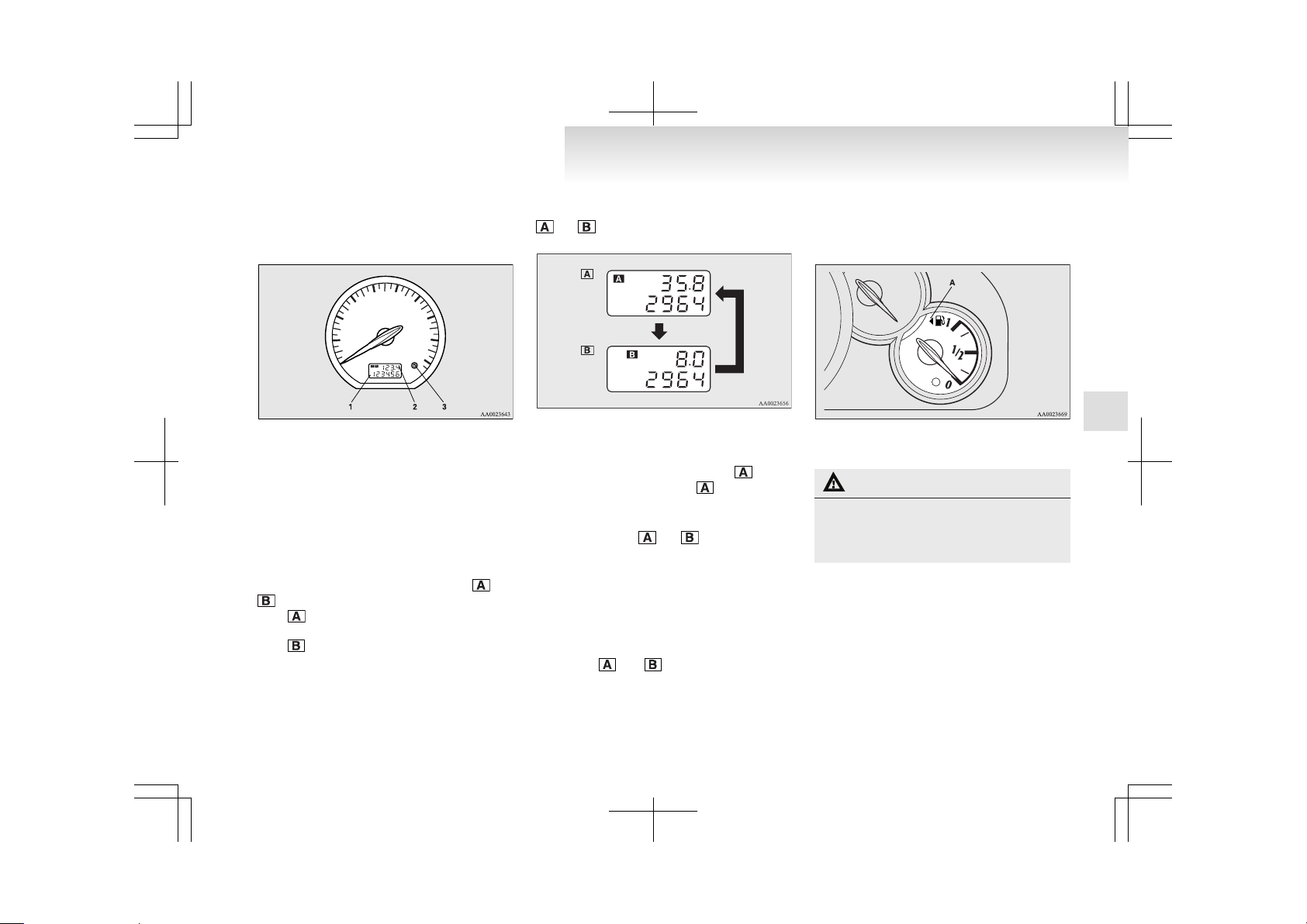
Odometer/Tripmeter
E00500600897
When the ignition key is turned to the “ON” position, odometer and tripmeter indications are given.
1- Odometer
2- Tripmeter
3- Reset button
Odometer
The odometer indicates the total distance the vehicle has travelled.
Tripmeter
The tripmeter indicates the distance travelled during a particular trip or period.
There are two tripmeter displays: TRIP
and
.
TRIP can be used to measure the distance travelled since the current trip began. At the same time,
TRIP can be used to measure the distance from
an intermediate location.
Every time the reset button (3) is pressed lightly
(less than 1 second), tripmeter indications (TRIP
and ) are changed.
TRIP
TRIP
To reset the tripmeter
To return the display to “0”, press the reset button
for more than 1 second. Only the currently dis-
played value will be reset. If TRIP is displayed, for example, only TRIP will be reset.
NOTE
l
Display TRIP
and each have a maxi-
mum distance of 999.9 km (999.9 miles).
l
Even when the ignition switch has been
turned to the “LOCK” position, pressing the
tripmeter reset button causes the odometer/
tripmeter indication to appear for approximately 30 seconds.
l
When disconnecting the battery terminal for
a long time, the memory of tripmeter display
TRIP and are cleared, and the display returns to “0”.
Fuel gauge
E00500700944
The fuel gauge indicates the fuel level in the fuel
tank when the ignition switch is in the “ON” position.
1- Full
0- Empty
CAUTION
l
For petrol-powered vehicles, do not drive
with an extremely low fuel level; running
out of fuel could cause damage to the catalytic converter.
Fuel lid mark
The fuel lid mark (A) indicates that the fuel tank filler door is located on the left side of the vehicle (Refer to “Filling the fuel tank” on page 03).
Instruments and controls
3-03
3
Page 81
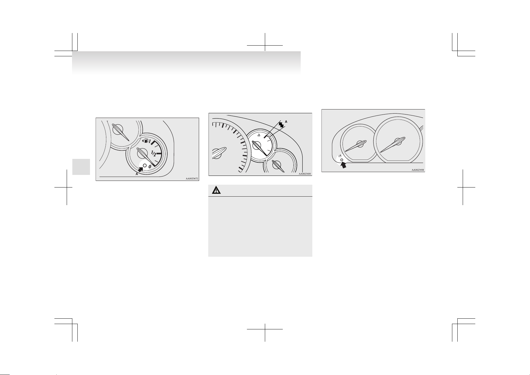
Low fuel warning lamp
E00508100638
The warning lamp (A) illuminates when the fuel level is getting low (approx. 10 litres) with the ignition switch in the “ON” position. Refuel as soon as
possible.
NOTE
l
On inclines or curves, due to the movement
of fuel in the tank, the low fuel warning lamp
may indicate incorrectly.
Water temperature gauge
E00500800495
The water temperature gauge indicates the engine
coolant temperature when the ignition switch is in
the “ON” position.
CAUTION
l
If the indication needle enters the zone
(A) while the engine is running, it indicates that the engine is possibly overheating. Immediately park your vehicle in a
safe place and make the necessary corrections. (Refer to “Engine overheating” on
page 6-04.)
While driving, care should always be taken to maintain the normal operating temperature.
Daytime dipper button
E00508800026
By pressing the daytime dipper button, you can
change the brightness of the backlighting in meters
and instrument panel.
NOTE
l
The brightness can be adjusted among 4 levels in accordance with the on/off condition of
the tail lamps.
NOTE
l
The meter brightness is memorized and maintained even if the ignition switch is turned to
the “LOCK” position.
Instruments and controls
3-04
3
Page 82

Indication and warning lamps
E00501501962
1-
CRUISE indication lamp* ® p. 4-26
2-
ASC indication lamp* ® p. 4-24
3-
Turn-signal indication lamps/Hazard warning indication lamps ® p. 3-06
4-
Rear fog lamp indication lamp ® p. 3-06
5-
Front fog lamp indication lamp ® p. 3-06
6-
High-beam indication lamp ® p. 3-06
7- Diesel particulate filter (DPF) warning lamp (diesel-powered vehi-
cles)* ® p. 4-12
8-
Position lamp indication lamp ® p. 3-06
9-
Automatic headlamp levelling warning lamp* ® p. 3-19
10-
Diesel preheat indication lamp (diesel-powered vehicles) ® p. 3-06
11-
Charge warning lamp ® p. 3-08
12-
Oil pressure warning lamp ® p. 3-08
13-
Check engine warning lamp ® p. 3-07, 3-08
14-
TCL OFF indication lamp* ® p. 4-24
15-
SONAR OFF indication lamp* ® p. 4-32
16-
Anti-lock brake system (ABS) warning lamp ® p. 4-21
17-
Brake warning lamp ® p. 3-06
18-
Seat belt reminder/warning lamp ® p. 2-19
19-
Sports mode indication lamp (vehicles with A/T) ® p. 4-18
20- Selector lever position indication lamps (vehicles with A/T, “N” indication
lamp is used also as A/T warning lamp) ® p. 4-16
21-
Supplemental restraint system (SRS) warning lamp ® p. 2-42
22-
Door ajar warning lamp ® p. 3-09
23-
Low fuel warning lamp ® p. 3-04
Instruments and controls
3-05
3
Page 83
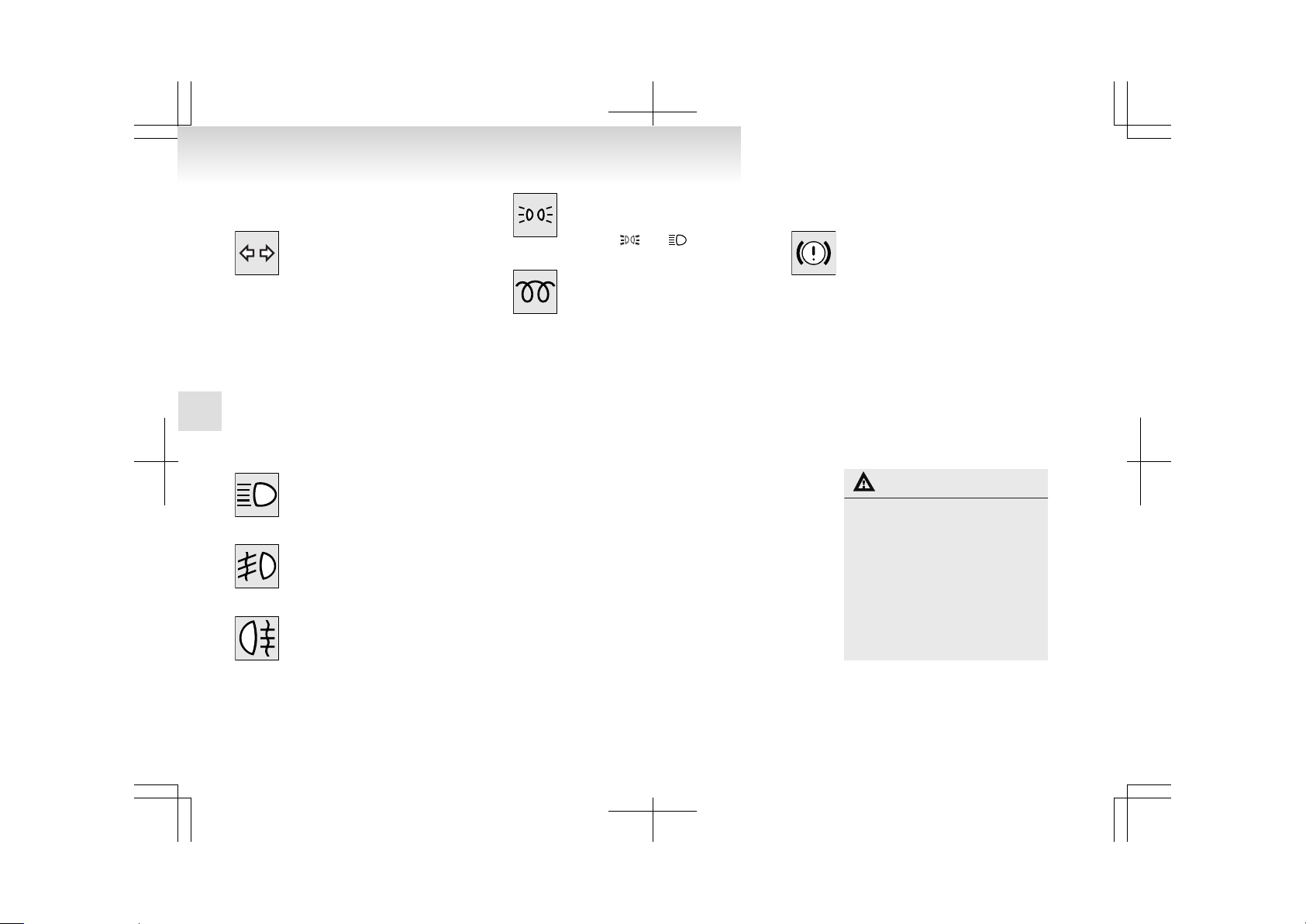
Indication lamps
E00501600012
Turn-signal indication lamps/ Hazard warning indication lamps
E00501700329
These indication lamps blink on and off
when a turn-signal lamp is operating.
NOTE
l
If the blinking is too fast, the
cause may be a blown lamp bulb
or a faulty turn-signal connection.
When the hazard warning lamp switch is
pressed, all turn-signal lamps will flash
on and off continuously.
High-beam indication lamp
E00501800160
This indication lamp illuminates when
the high-beam is used.
Front fog lamp indication lamp
E00501900321
This lamp illuminates while the front
fog lamps are on.
Rear fog lamp indication lamp
E00502000101
This lamp illuminates while the rear fog
lamp is on.
Position lamp indication lamp
E00508900102
This lamp illuminates with the lamp
switch at “ ” or “ ” position
Diesel preheat indication lamp (diesel-powered vehicles)
E00502300061
This indication lamp illuminates when
the ignition switch is placed in the “ON”
position. As the glow plug becomes hot,
the lamp goes out and the engine can be
started. If it does not go off after a few
seconds, we recommend you to have the
vehicle checked.
NOTE
l
If the engine is cold, the diesel preheat indication lamp is on for a longer time.
l
When the engine has not been started within about 5 seconds after
the diesel preheat indication lamp
went out, return the ignition
switch to the “LOCK” position.
Then, turn the switch to the “ON”
position to preheat the engine
again.
l
When the engine is warm, the diesel preheat indication lamp does
not come on even if the ignition
switch is placed in the “ON” position.
Warning lamps
E00502400017
Brake warning lamp
E00502501930
This lamp illuminates when the ignition
switch is turned to the “ON” position,
and the lamp goes off after a few seconds.
Always make sure that the lamp goes off
before driving.
With the ignition switch in the “ON” position, the brake warning lamp illuminates under the following conditions:
l
When the parking brake lever has
been engaged.
l
When the brake fluid level in the
reservoir falls to a low level.
l
When the brake force distribution
function is not operating correctly.
CAUTION
l
In the situations listed below,
brake performance may be compromised or the vehicle may become unstable if brakes are applied suddenly; consequently,
avoid driving at high speeds or
applying the brakes suddenly.
Furthermore, the vehicle
should be brought to a stop in a
safe location and to have it
checked.
Instruments and controls
3-06
3
Page 84
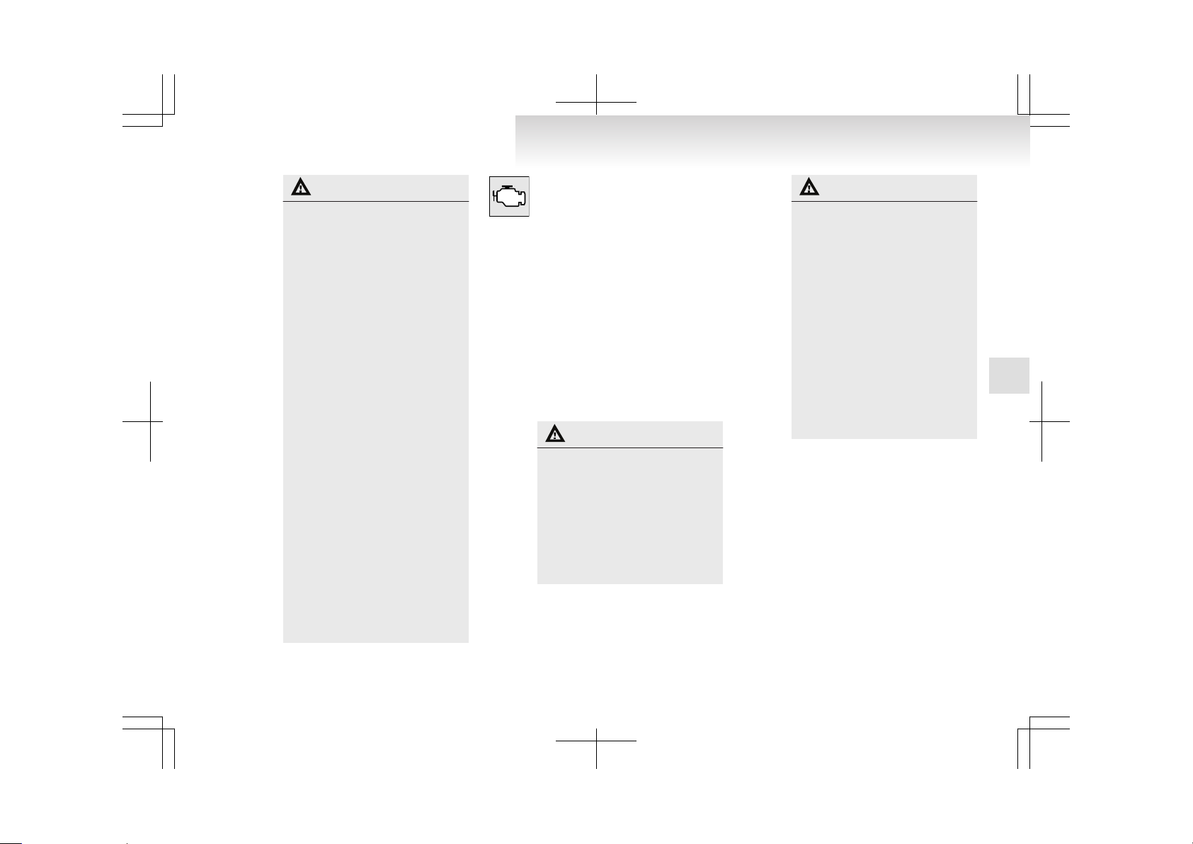
CAUTION
• The brake warning lamp
does not illuminate when
the parking brake is applied
or does not turn off when
the parking brake is released.
• The ABS warning lamp and
brake warning lamp illuminate at the same time.
For details, refer to “ABS
warning lamp” on page
4-21.
• The brake warning lamp remains illuminated during
driving.
l
The vehicle should be brought
to a halt in the following manner when brake performance
has deteriorated.
• Depress the brake pedal
harder than usual.
Even if the brake pedal
moves down to the very end
of its possible stroke, keep it
pressed down hard.
• Should the brakes fail, use
engine braking to reduce
your speed and carefully
pull the parking brake lever
to park your vehicle.
Depress the brake pedal to
operate the stop lamp
(brake lamp) to alert the vehicles behind you.
Check engine warning lamp (petrol-powered vehicles)
E00502601351
This lamp is a part of an onboard diagnostic system which monitors the emissions, engine and automatic transmission
control systems.
If a problem is detected in one of these
systems, this lamp illuminates.
Although your vehicle will usually be
drivable and not need towing, we recommend you to have the system checked as
soon as possible.
This lamp will also illuminate for a few
seconds when the ignition key is turned
to the “ON” position. If it does not go
off after a few seconds, we recommend
you to have the vehicle checked.
CAUTION
l
Prolonged driving with this
lamp on may cause further damage to the emission control system. It could also affect fuel
economy and drivability.
l
If the lamp does not illuminate
when the ignition key is turned
to the “ON” position, we recommend you to have the system
checked.
CAUTION
l
If the lamp illuminates while
the engine is running, avoid
driving at high speeds and we
recommend you to have the system checked.
During vehicle operation with
the lamp illuminated, the vehicle may not accelerate when
you depress the accelerator pedal.
When the vehicle is stationary
with the lamp illuminated, you
must depress the brake pedal
more firmly than usual since
the engine idling speed is higher than usual and the vehicle
with an A/T has a stronger tendency to creep forward.
NOTE
l
The engine electronic control module accommodating the onboard diagnostic system has various fault
data (especially about the exhaust
emission) stored.
This data will be erased if a battery cable is disconnected which
will make a rapid diagnosis difficult. Do not disconnect a battery
cable when the check engine warning lamp is ON.
Instruments and controls
3-07
3
Page 85

Check engine warning lamp (diesel-powered vehicles)
E00502600628
This lamp is a part of an onboard diagnostic system which monitors the emissions control systems.
If a problem is detected in one of these
systems, this lamp illuminates.
Although your vehicle will usually be
drivable and not need towing, we recommend you to have the system checked as
soon as possible.
This lamp will also illuminate for a few
seconds when the ignition key is turned
to the “ON” position. If it does not go
off after a few seconds, we recommend
you to have the vehicle checked.
CAUTION
l
Prolonged driving with this
lamp on may cause further damage to the emission control system. It could also affect fuel
economy and drivability.
l
If the lamp does not illuminate
when the ignition key is turned
to the “ON” position, we recommend you to have the system
checked.
CAUTION
l
If the lamp illuminates while
the engine is running, avoid
driving at high speeds and we
recommend you to have the system checked.
During vehicle operation with
the lamp illuminated, the vehicle may not accelerate when
you depress the accelerator pedal.
When the vehicle is stationary
with the lamp illuminated, you
must depress the brake pedal
more firmly than usual since
the engine idling speed is higher than usual.
NOTE
l
The engine electronic control module accommodating the onboard diagnostic system has various fault
data (especially about the exhaust
emission) stored.
This data will be erased if a battery cable is disconnected which
will make a rapid diagnosis difficult. Do not disconnect a battery
cable when the check engine warning lamp is ON.
Charge warning lamp
E00502700935
This lamp illuminates when the ignition
key is turned to the “ON” position, and
goes off after the engine has started.
CAUTION
l
If it illuminates while the engine is running, there is a problem in the charging system. In
this case, immediately park
your vehicle in a safe place and
we recommend you to have it
checked.
Oil pressure warning lamp
E00502800659
This lamp illuminates when the ignition
key is turned to the “ON” position, and
goes off after the engine has started. If it
illuminates while the engine is running,
the oil pressure is too low.
If the warning lamp illuminates while
the engine is running, turn the engine off
and have it inspected.
CAUTION
l
If this lamp illuminates when
the engine oil level is not low,
have it inspected.
l
This warning lamp does not indicate the amount of oil in the
crankcase.
This must be determined by
checking the oil level on the dipstick, while the engine is switched off.
Instruments and controls
3-08
3
Page 86
CAUTION
l
If you continue driving with
low engine oil level or with this
warning lamp illuminated, engine seizure may occur.
NOTE
l
The oil pressure warning lamp
should not be treated as an indication of the engine’s oil level. The
oil level must be checked using
the dipstick.
Door ajar warning lamp
E00503300765
This lamp illuminates when a door or
the tailgate is either open or incompletely closed.
If the vehicle speed reaches approximately 8 km/h (5 mph) with a door or the tailgate open or incompletely closed, the
warning lamp flashes 8 times and a buzzer simultaneously sounds 8 times as a
warning.
CAUTION
l
Before moving your vehicle,
check that the warning lamp is
OFF.
NOTE
l
On vehicles with keyless entry system, the lamp remains illuminated
for a certain period and then goes
out automatically. Refer to
“Lamps (room lamps, etc.) autocutout function” on page 5-37.
l
It is possible to change the buzzer
setting for either of the following
types of operation. For further information, we recommend you to
consult a MITSUBISHI
MOTORS Authorized Service
Point.
• No buzzer operation (buzzer
disabled)
• Continuous buzzer operation
Multi centre display
E00503600120
WARNING
l
When operating the system for a prolonged period, make sure the vehicle is
parked in a well ventilated area to avoid
the accumulation of toxic fumes inside
and outside of the passenger compartment.
CAUTION
l
The driver should not operate the display
while the vehicle is in motion.
l
When operating the system, stop the vehicle in a safe area.
When the ignition switch is in the “ACC” position,
the digital clock is displayed in the multi centre display. When the ignition switch is in the “ON” position, the momentary fuel consumption and outside
temperature are displayed besides digital clock.
Instruments and controls
3-09
3
Page 87

A-
Outside temperature ® p. 3-12
B-
Driving information ® p. 3-13
C-
Digital clock ® p. 3-10
NOTE
l
The display unit (ex. km or mile) and brightness can be changed as desired. (Refer to
“Display brightness adjustment” on page
3-16 and “Display unit selection” on page
3-16.) When the system cannot provide a definite value for momentary fuel consumption/
average fuel consumption/driving range/average speed, it is displayed as “---”.
l
The figure of the display varies according to
the conditions under which a vehicle is travelling (road conditions, the manner in which
the vehicle is being driven, etc.).
Observe display for reference because the figure of the display may differ from the actual
figure.
Digital clock
E00503700118
Following modes are available for digital clock adjustment:
l
For vehicles with MITSUBISHI MOTORS
genuine audio automatic mode and manual
mode
l
Except for vehicles with MITSUBISHI
MOTORS genuine audio manual mode only
Select the automatic mode or the manual mode by
performing the following operations:
1. Enter the function setup mode by pushing
the “MENU” button.
Instruments and controls
3-10
3
Page 88
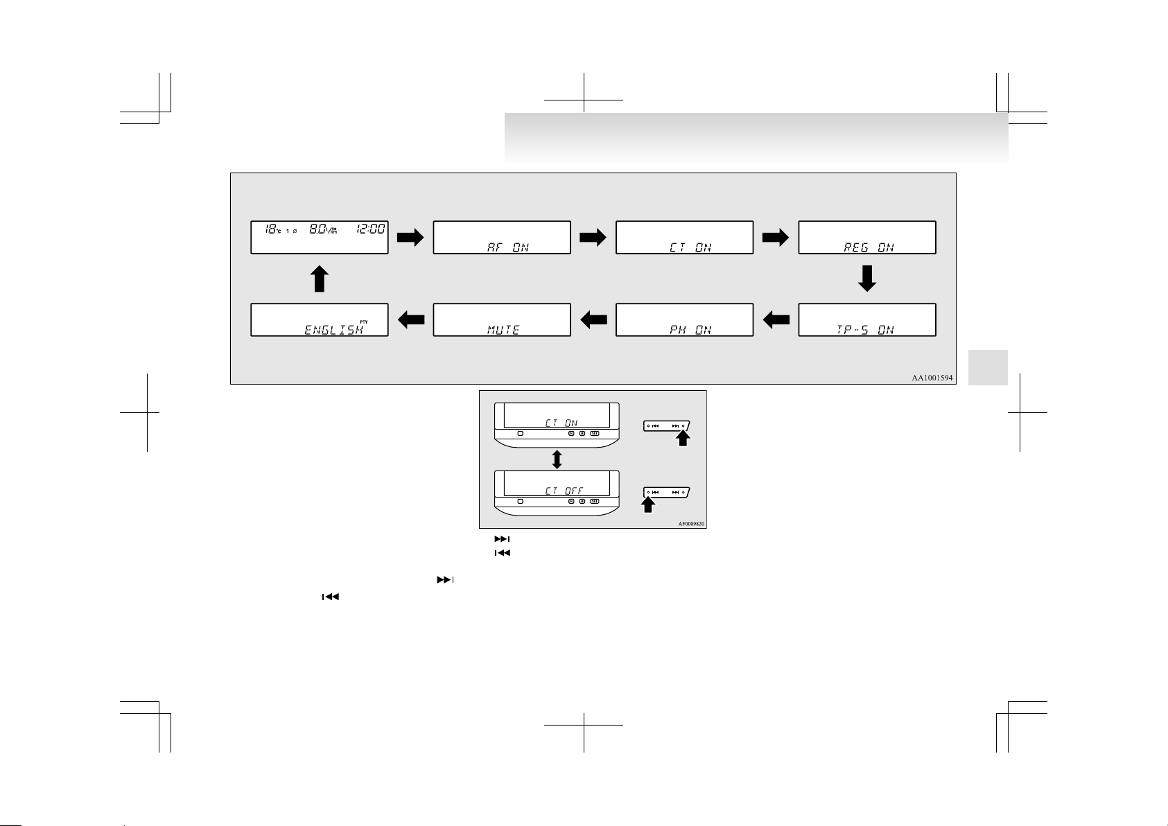
2. Press the “MENU” button repeatedly to select the CT (Clock Time) mode.
The order is: AF → CT → REG → TP-S →
PH → MUTE (With PH OFF, this mode is
not displayed.) → Language of PTY display
→ Function setup mode OFF
(Refer to “Function setup mode” on page
5-21.)
NOTE
l
Although “PH” and “MUTE” appear on the
display, the PH and MUTE functions are inoperative.
3.
Make your selection by pressing the “ ”
button or the “ ” button.
- CT ON (Automatic mode)
- CT OFF (Manual mode)
NOTE
l
After selecting a mode, you can leave the function setup mode by taking either of the following steps:
• Press the “MENU” button for at least 2
seconds.
• Make no entry for 7 seconds.
Instruments and controls
3-11
3
Page 89
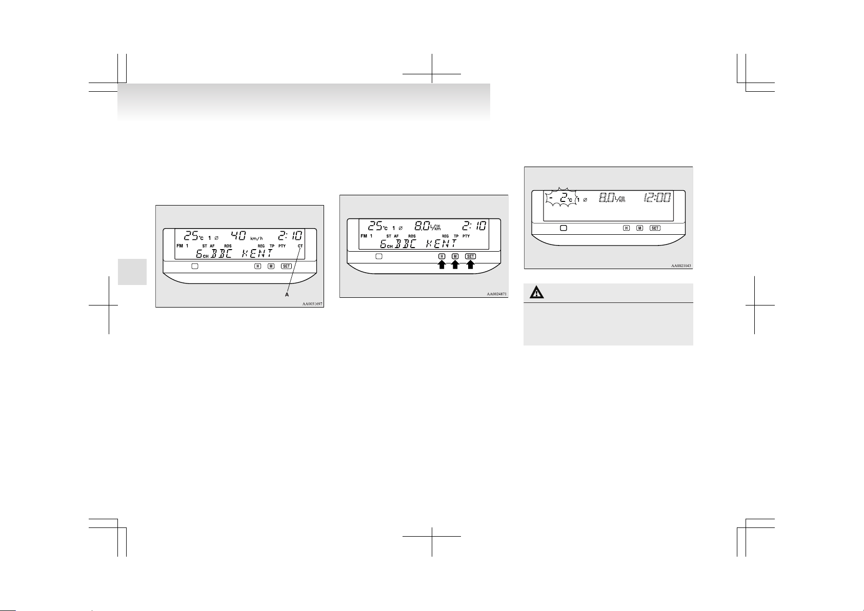
Automatic mode (For vehicles with MITSUBISHI MOTORS genuine audio)
The automatic adjustment mode can set the local
time automatically by using the signal from local
RDS stations. In this mode, CT (A) is shown in the
display. Refer to “Radio data system (RDS)” on
page 5-18.
Manual mode
The manual mode is also available in case the automatic mode shows the incorrect time when the adjacent local RDS stations are located in a different
time zone. Refer to “Radio data system (RDS)” on
page 5-18.
Set the time by pressing the various buttons as
described below.
H- To adjust the hour
M- To adjust the minutes
SET- To reset the minutes to zero
10:30-11:29…Changes to 11:00
11:30-12:29…Changes to 12:00
Outside temperature
E00503900019
This value shows the outside temperature of the vehicle.
If the outside air temperature drops below approx.
3 °C, the alarm sounds and the outside air temperature figure flashes for about 10 seconds.
CAUTION
l
There is a danger the road might be icy,
even when the outside air temperature figure is not flashing, so please take care
when driving.
NOTE
l
The outside temperature can be displayed
from -40 °C to 50 °C.
l
The outside temperature displayed may differ from the actual temperature on account of
surrounding conditions, driving conditions,
etc.
l
When the outside temperature is below
-40 °C or over 50 °C, the display will remain
-40 °C or 50 °C.
Instruments and controls
3-12
3
Page 90
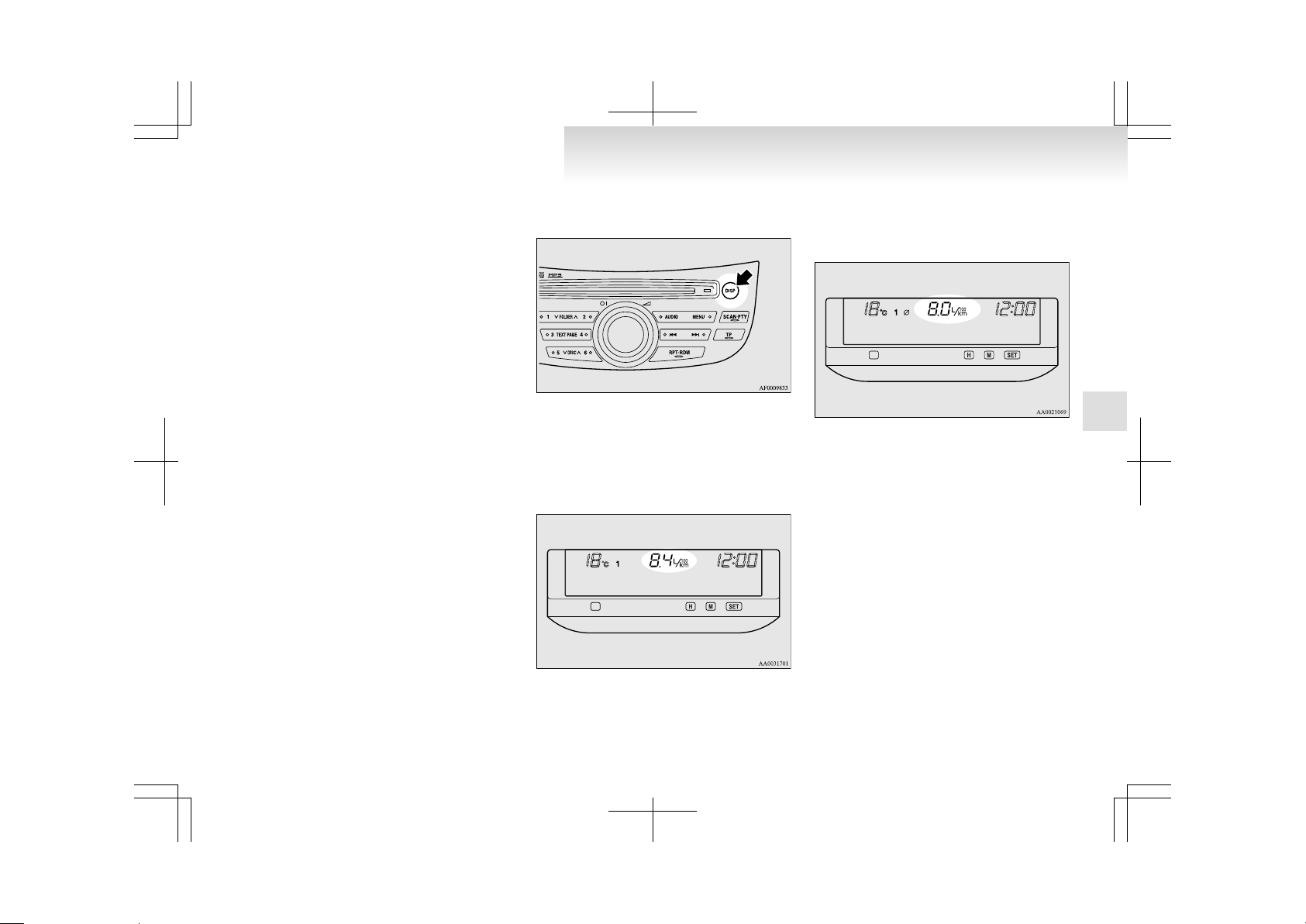
Driving information
E00509000067
For vehicles with MITSUBISHI MOTORS genuine audio
The momentary fuel consumption, average fuel consumption, driving range and average speed can be
displayed.
When the ignition switch is turned to the “ON” position, the display shows the 4 items sequentially
and returns to the original display that is shown before the ignition switch was last turned to the
“OFF” position.
NOTE
l
If the “DISP” button is pressed while the display is scrolling through the sequence mentioned above, the display stops scrolling and
shows the item that was shown before the ignition switch was last turned to the “OFF” position.
Except for vehicles with MITSUBISHI MOTORS genuine audio
Only the momentary fuel consumption can be displayed. Refer to “Momentary fuel consumption”
on page 3-13.
Change of driving information (For vehicles with MITSUBISHI MOTORS genuine audio)
E00509100068
Every time the “DISP” button is pressed lightly
(less than 5 seconds), the display can be changed.
Momentary fuel consumption → Average fuel consumption → Driving range → Average speed
Momentary fuel consumption
E00509200014
This value shows the momentary fuel consumption
(in L/100 km, km/L or mpg). Calculation and indication of the value begin when the vehicle speed
rises above 6 km/h (4 mph).
Average fuel consumption
E00509300073
This value shows the average fuel consumption (in
L/100 km, km/L or mpg).
NOTE
l
When the ignition switch is turned to the
“ON” position, the average fuel consumption
which was being displayed when the ignition
switch was previously turned off will be displayed once again.
l
Average fuel consumption varies according
to the conditions under which a vehicle is travelling (road conditions, the manner in which
the vehicle is being driven, etc.).
Observe this display for reference because
the fuel consumption display may differ
from the actual fuel consumption.
To reset the display
You can switch from the automatic reset mode to
the manual reset mode by performing the following
operations:
Instruments and controls
3-13
3
Page 91
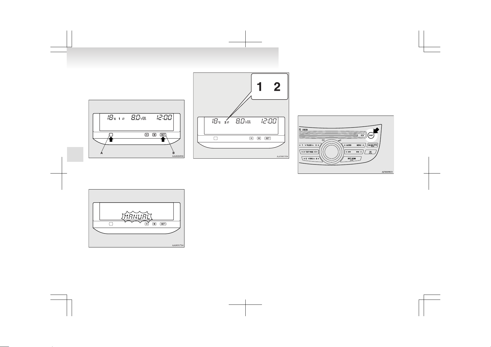
1. Press and hold down button (A), then press
the “SET” button (B) within 1 second, and a
buzzer will sound and the reset mode will be
changed.
2. The name of the newly selected mode will
flash, then the display will return to its original indications.
3. The status of the selected mode will be
shown on the display.
or
1- Automatic reset mode
2- Manual reset mode
l
Automatic reset mode
When 4 hours have passed after the ignition
switch is turned to the “OFF” or “ACC” position, the display is automatically reset. It
then shows “---”.
l
Manual reset mode
If you reset the display at the time when you
want to start the measurements, average fuel
consumption from that point of time can be
displayed.
Push the “DISP” button for more than 5 seconds.
NOTE
l
While the ignition switch is in the “ON” position, the automatic reset mode is permanently selected. If you wish to make continuous
measurements, select the manual mode.
Instruments and controls
3-14
3
Page 92

Driving range
E00509400016
This value shows the distance (in km or miles) that
can be driven on the fuel remaining in the fuel tank.
NOTE
l
If the driving range drops below 50 km
(30 miles) while the driving range is displayed, the display shows “---”. When this occurs, top up the fuel tank as soon as possible.
l
The driving range varies depending on road
conditions, the manner of driving and other
related factors. Consequently, the display
should be used only as a guide. It is recommended to add fuel as soon as the low fuel
warning lamp in the instrument cluster illuminates.
(Refer to “Low fuel warning lamp” on page
3-04.)
l
Refueling will update the driving range indication.
l
The driving range displayed is based on previous fuel consumption data. Disconnecting
the battery cable will result in the deletion of
existing fuel consumption data, which will affect the unit’s calculations.
l
The driving range figure can occasionally increase if the vehicle is stopped on an incline.
This is because the fuel has moved in the
tank because of the incline and is not considered as a fault.
Average speed
E00509500062
This value shows the average speed (in km/h or
mph) since the display was reset. Refer to “To reset
the display” on page 3-13.
l
Automatic reset mode
When 4 hours have passed after the ignition
switch is turned to the “OFF” or “ACC” position, the display is automatically reset. It
then shows “---”.
l
Manual reset mode
If you reset the display at the time when you
want to start the measurements, average
speed from that point of time can be displayed.
To reset the display, push the “DISP” button
for about 5 seconds or more.
NOTE
l
While the ignition switch is in the “ON” position, the automatic reset mode is permanently selected. If you wish to make continuous
measurements, select the manual mode.
Instruments and controls
3-15
3
Page 93
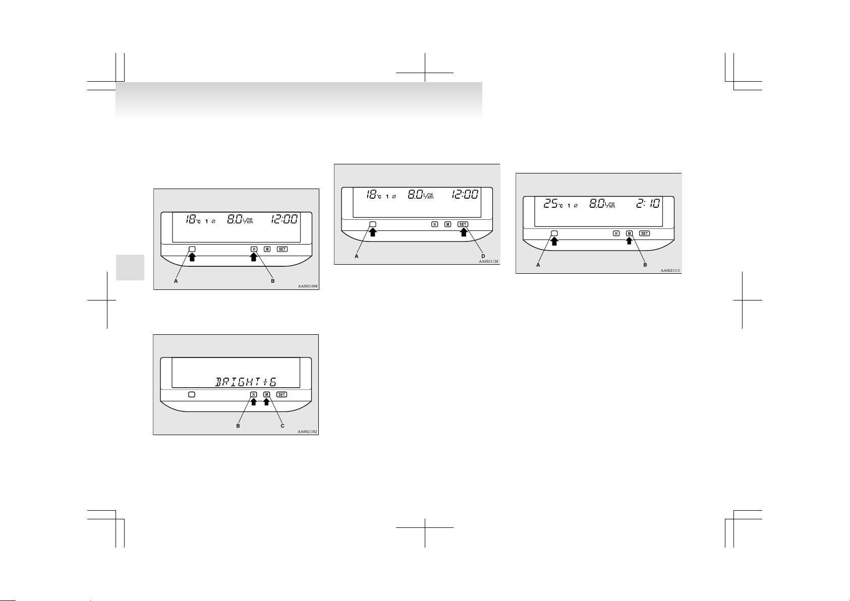
Display brightness adjustment
E00509600018
1. Press and hold down button (A), then press
the “H” button (B) within 1 second. A buzzer will sound, and the system will allow adjustment of the display brightness.
2.
Adjust the brightness by pressing the “H” button (B) or “M” button (C).
H- Decrease brightness
M- Increase brightness
3. Press the “SET” button (D) to determine the
setting. The display will return to the original
display item.
NOTE
l
To cancel the brightness adjusting procedure
before completion, press the button (A).
l
If the “SET” button (D) is not pressed for
about 15 seconds or longer in the middle of
the adjustment, the currently selected brightness is set automatically. The display will return to the original display item.
Display unit selection
E00509700051
It is possible to change the units in which distance,
fuel consumption, and time are displayed.
NOTE
l
Except for vehicles with MITSUBISHI
MOTORS genuine audio, only the unit of momentary fuel consumption can be changed to
km or miles.
1. Press and hold down button (A), then press
the “M” button (B) within 1 second. A buzzer will sound, and the system will allow
units to be changed.
2. Use the “H” button (C) or “M” button (B) to
select the desired speed unit, then press the
“SET” button (D) to enter the setting.
Instruments and controls
3-16
3
Page 94
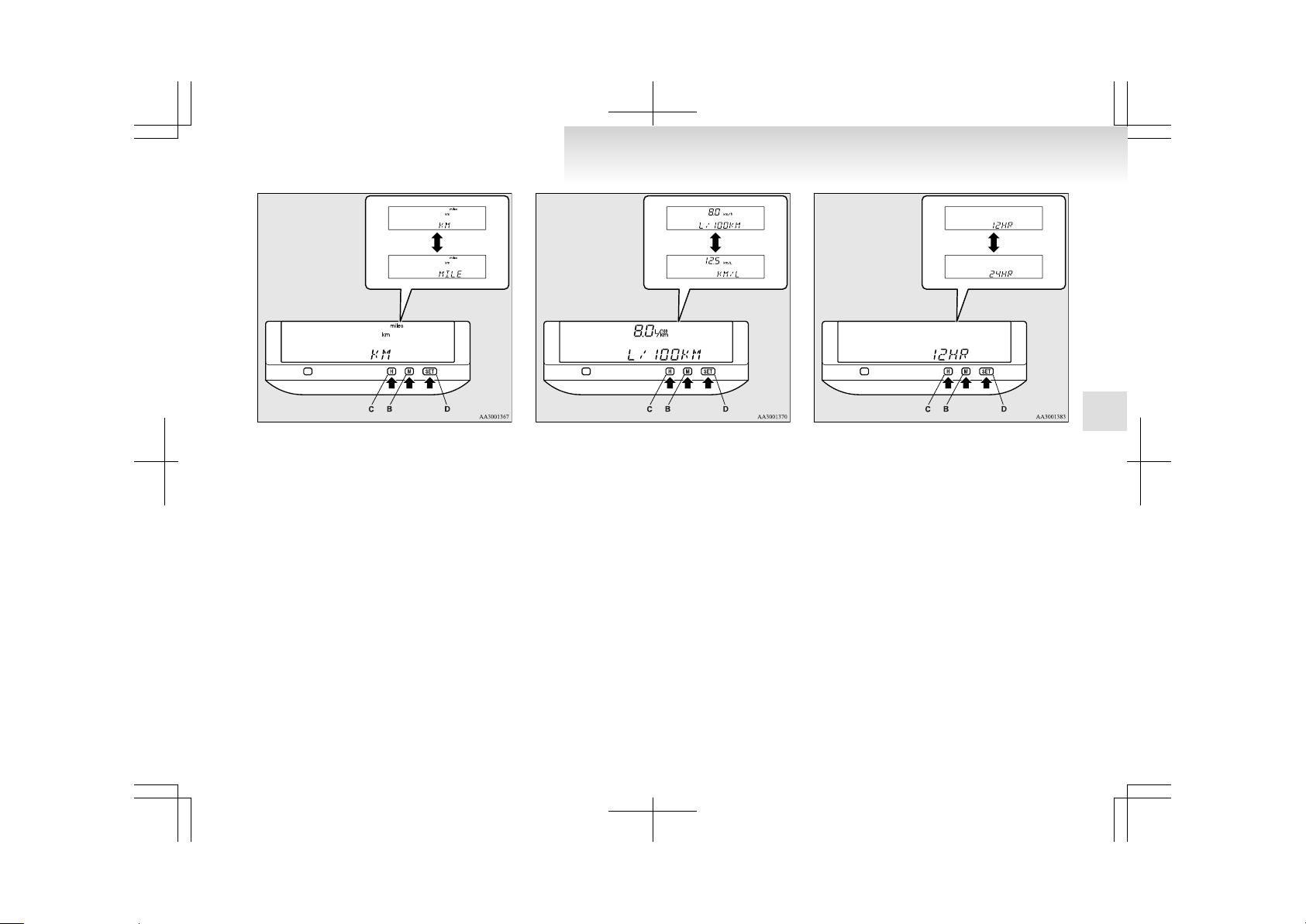
H - km
M - mile
3. If the km unit was selected in step 2, the fuel
consumption unit must be subsequently selected using the “H” button (C) or “M” button
(B).
Use the “H” button (C) or “M” button (B) to
select the desired fuel consumption unit, then
press the “SET” button (D) to enter the setting.
H - L/100 km
M - km/L
4. When you have finished setting the fuel consumption unit (or if you selected miles in
step 2), the system will require you to proceed to select, using the “H” button (C) or
“M” button (B), whether times should be displayed in the 12-hour format or in the
24-hour format. The currently selected format will be displayed.
Use the “H” button (C) or “M” button (B) to
choose your desired time display format, and
then press the “SET” button (D) to enter the
setting.
H - 12-hour format
M - 24-hour format
5. The display will return to the original display
item.
NOTE
l
If you selected the mile unit in step 2, the
speed and fuel consumption units will be as
follows.
• Speed: mph (miles per hour)
• Fuel consumption: mpg (miles per gallon)
Instruments and controls
3-17
3
Page 95
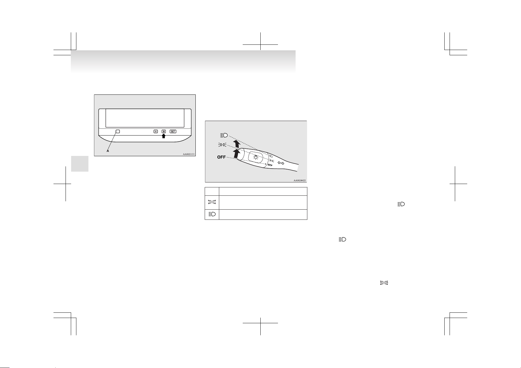
l
To cancel the unit setting procedure before
completion, press the button (A).
l
The outside temperature and digital clock are
not shown during the unit selecting procedure.
l
If the “SET” button is not pressed for about
15 seconds or longer in the middle of the selection, the currently selected unit is set automatically. The display will return to the original display item.
Combination headlamps and
dipper switch
E00506000776
Headlamps
Rotate the switch to turn on the lamps.
OFF All lamps off
Position, tail, licence plate and instrument
panel lamps on
Headlamps and other lamps go on
NOTE
l
Do not leave the headlamps and other lamps
on for a long while the engine is stationary.
A run-down battery could result.
l
When it rains or when the vehicle has been
washed, the inside of the lens sometimes becomes foggy. This is the same phenomenon
as when window glass mists up on a humid
day, and does not indicate a functional problem. When the lamp is switched on, the heat
will remove the fog. However, if water gathers inside the lamp, we recommend you to
have it checked.
[Vehicles with Daytime Running Lamp]
When the ignition switch is in the “ON” position
and the lamp switch is set to the “OFF” position,
the low beam of the headlamps, tail lamps, etc.,
will illuminate.
Lamps (headlamps, fog lamp, etc.) auto-cutout function
l
If the key is turned to the “LOCK” or
“ACC” position or removed from the ignition switch and the lamps will stay on for
about 3 minutes without opening the driver’s
door while the lamp switch in the “ ” position, automatically turn off.
l
If the key is turned to the “LOCK” or
“ACC” position or removed from the ignition switch and the driver’s door is opened
within 3 minutes while the lamp switch in
the “ ” position, a buzzer will sound to
warn the driver that the lamps have not been
turned off, and these lamps will automatically turn off.
NOTE
l
The lamp auto-cutout will not function when
the lamp switch is in the “
” position.
Instruments and controls
3-18
3
Page 96
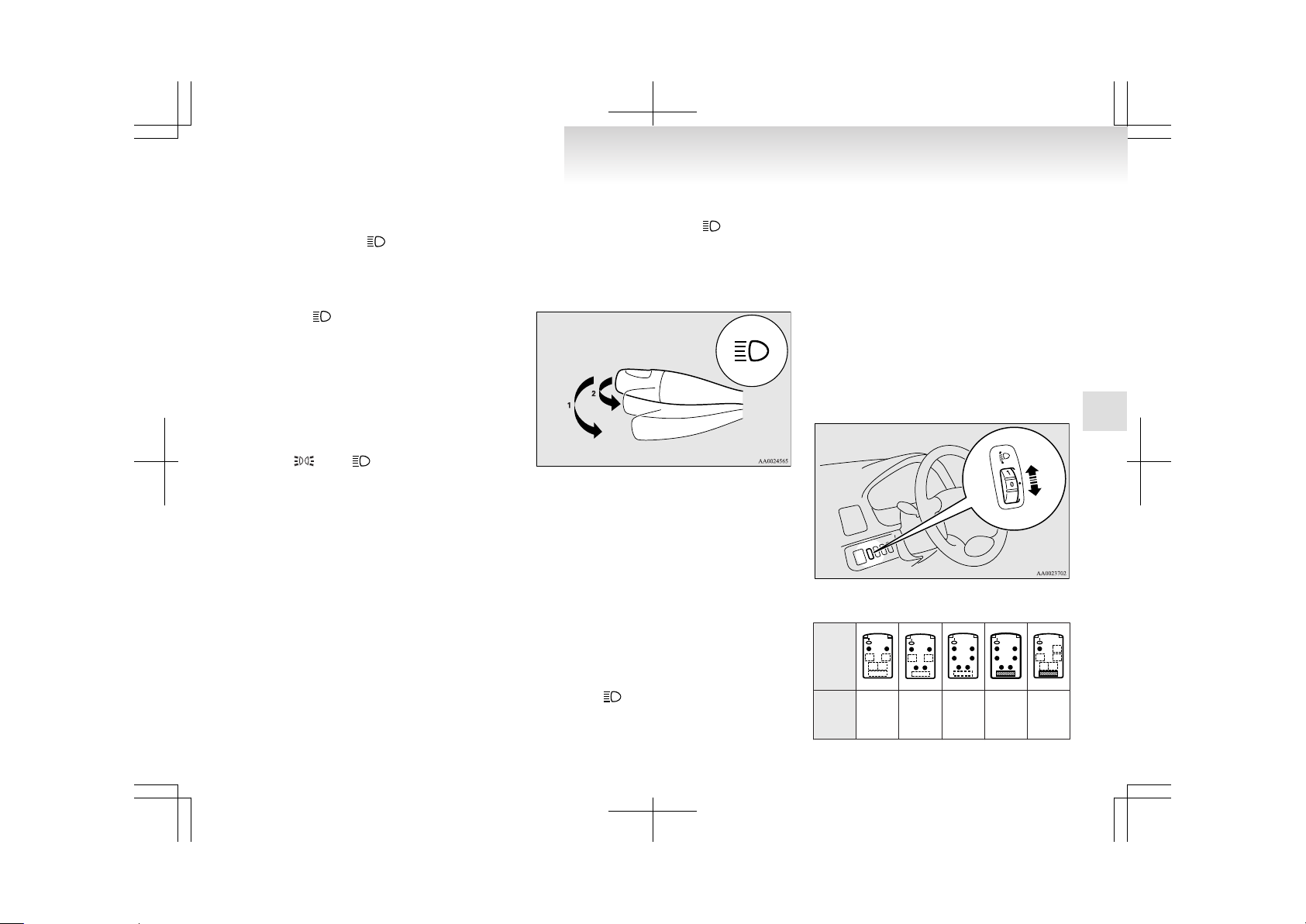
l
When the key has been turned to either the
“LOCK” or “ACC” position or removed
from the ignition switch with the lamp
switch in the “ ” position, and the lamp
switch is turned to the “OFF” position within
approximately 3 minutes, the auto-cutout
function will not be activated.
(Even if the lamp switch is again turned to
the “ ” position, the lamps will not go off
automatically; the lamps will remain on as
normal.)
When you want to keep the lamps on
l
Turn the switch in the “OFF” position to
switch off all lamps while the key is in the
“LOCK” or “ACC” position or remove the
key from the ignition switch.
l
Turn on the lamps with the switch in the
“
” or “ ” position again, then the
lamps will remain on.
NOTE
l
It is possible to disable the lamps auto-cutout
function. For further information, we recommend you to consult a MITSUBISHI
MOTORS Authorized Service Point.
Lamp monitor buzzer
E00506100012
If the driver’s door is opened when the key is in the
“LOCK” or “ACC” position or removed from the
ignition switch while the lamps are on, a buzzer
will sound to remind the driver to turn off the
lamps. When the lamp auto-cutout function acts,
the buzzer will stop automatically. When this function does not act, turn off the lamp switch to stop
the buzzer.
Dipper (High/Low beam change)
E00506200114
When the lamp switch is in the “ ” position, the
beam changes from high to low (or low to high)
each time the lever is pulled to (1). While the highbeam is on, the high-beam indication lamp in the instrument cluster will also illuminate.
Headlamp flasher
E00506300333
The high-beams flash when the lever is pulled slightly (2), and will go off when it is released.
When the high-beam is on, the high-beam indication lamp in the instrument cluster will illuminate.
NOTE
l
The high-beams can also flash when the
lamp switch is OFF.
l
If you turn the lamps off with the headlamps
set to high-beam illumination, the headlamps
are automatically returned to their low-beam
setting when the lamp switch is next turned
to the “
” position.
Headlamp levelling
E00506400767
Headlamp levelling switch*
Except for vehicles with discharge headlamps
The angle of the headlamp beam varies depending
on the load carried by the vehicle.
The headlamp levelling switch can be used to adjust the headlamp illumination distance (when the
lower beam is illuminated) so that the headlamps’
glare does not distract other drivers.
Set the switch (referring to the following table) to
the appropriate position according to the number of
people and the load in the vehicle.
<6-person seat>
Vehi-
cle
condi-
tion
Switch
posi-
tion
“0” “1” “2” “3” “4”
Instruments and controls
3-19
3
Page 97

●:1 person
:Full luggage loading
Switch position 0- Driver only/Driver + 1 front
passenger
Switch position 1- Driver + 1 front passenger +
2 third seat passengers
Switch position 2- All passengers
Switch position 3- All passengers + Full luggage
loading
Switch position 4- Driver + Full luggage loading
<7-person seat>
Vehi-
cle
condi-
tion
Switch
posi-
tion
“0” “1” “2” “3” “4”
●:1 person
:Full luggage loading
Switch position 0- Driver only/Driver + 1 front
passenger
Switch position 1- Driver + 1 front passenger +
2 third seat passengers
Switch position 2- All passengers
Switch position 3- All passengers + Full luggage
loading
Switch position 4- Driver + Full luggage loading
Automatic headlamp levelling*
Vehicles with discharge headlamps
This function automatically adjusts the illumination distance of the headlamps according to the number of people and the load in the vehicle.
When the ignition switch is in the “ON” position
and the lamp switch is in the “ ” position, the illumination distance of the headlamps is automatically adjusted when the vehicle is stopped or travelling at a constant speed.
Automatic headlamp levelling warning lamp
The automatic headlamp levelling warning lamp
should illuminate when the ignition switch is
turned to the “ON” position, and should go off in a
few seconds.
CAUTION
l
If the warning lamp stays on or does not
illuminate when the ignition switch is
turned to the “ON” position, it indicates
that the automatic headlamp levelling device is not functioning.
We recommend you to have your vehicle
inspected.
Instruments and controls
3-20
3
Page 98

Turn/Lane-change signals
E00506501156
The turn-signal lamps flash when the switch is operated (with the ignition switch in the “ON” position). At the same time, the turn signal indicator
flashes.
1- Turn-signals
When making a normal turn, use position
(1). The lever will return automatically when
cornering is completed.
There are times when the lever will not return after cornering. This occurs when the
steering wheel is turned only slightly.
In such cases, return the lever by hand.
2- Lane-change signals
When changing lanes, use position (2). It
will return to the neutral position when released.
NOTE
l
If the lamp flashes unusually quickly, the
bulb in a turn-signal lamp may have burned
out. We recommend you to have the vehicle
inspected.
l
It is possible to activate the following functions. For further information, we recommend you to consult a MITSUBISHI
MOTORS Authorized Service Point.
On a vehicle equipped with a Multi Display
Station (MDS), the functions can be adjusted
on the screen. Refer to the separate operation
manual for details.
• Sounding of a buzzer as the turn-signal
lamps flash.
• Flashing of the turn-signal lamps and the
indication lamp in the meter when the lever is operated with the ignition switch in
the “ACC” position.
Hazard warning flasher switch
E00506600567
Use the hazard warning flasher switch when the vehicle has to be parked on the road for any emergency.
The hazard warning flashers can always be operated, regardless of the position of the ignition key.
Push the switch to turn on the hazard warning flashers; push the switch again to turn them off.
When this switch is operated, all turn-signal lamps
flash continuously, as do the turn-signal indication
lamps in the instrument cluster.
NOTE
l
If the lamps are kept flashing for a long time,
the battery will be discharged, resulting in
hard engine starting or no start condition.
Instruments and controls
3-21
3
Page 99
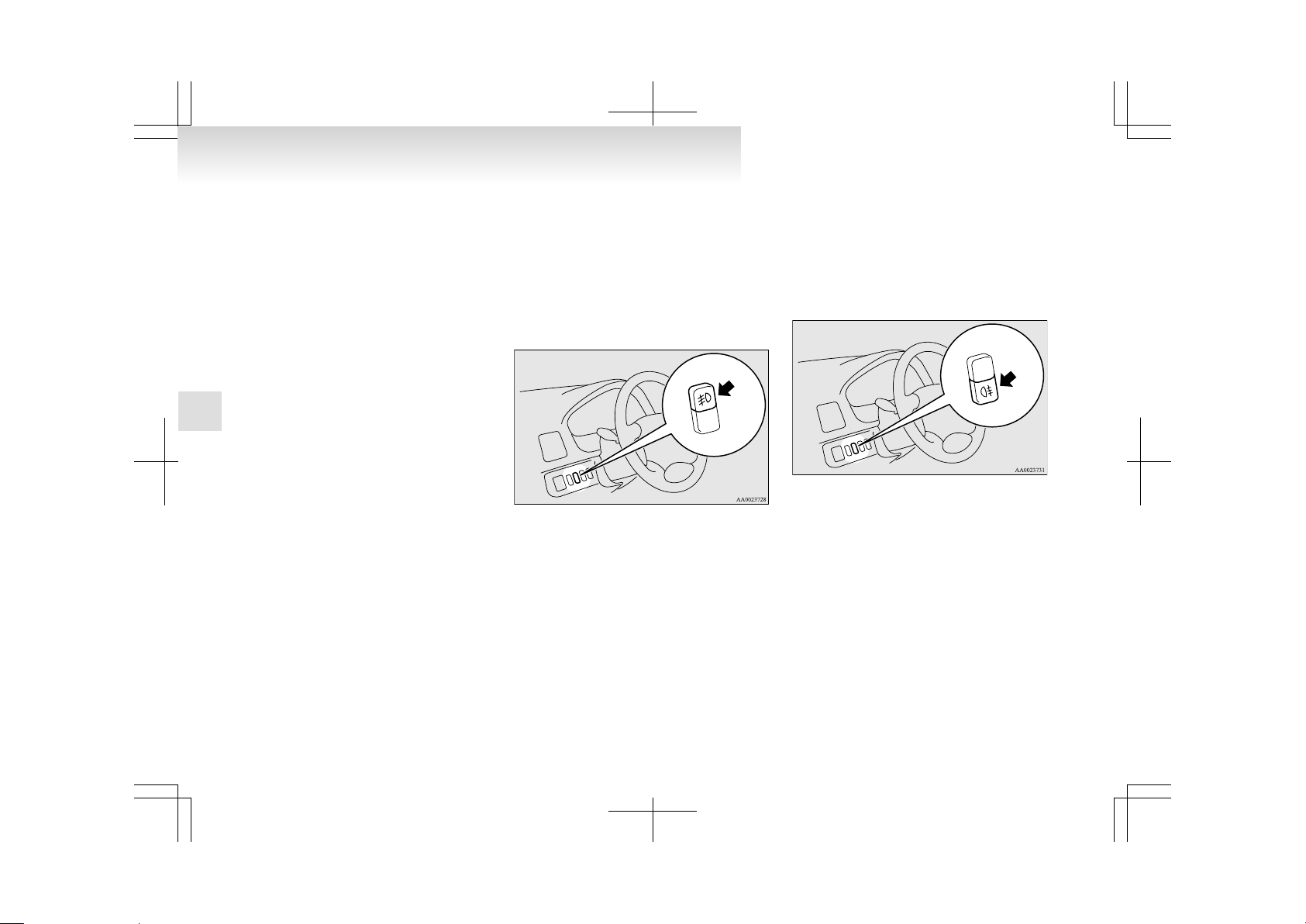
l
It is possible to cause a buzzer to sound in
time with flashing of the turn-signal lamps.
For further information, we recommend you
to consult a MITSUBISHI MOTORS Authorized Service Point.
On a vehicle equipped with a Multi Display
Station (MDS), the functions can be adjusted
on the screen. Refer to the separate operation
manual for details.
Fog lamp switch
E00506700018
Front fog lamp switch
E00508300050
The front fog lamp can be operated when the headlamps or tail lamps turn on. Push the switch to turn
on the front fog lamps, and push the switch again
to turn them off.
The indication lamp in the instrument cluster will
illuminate while the front fog lamps are on.
NOTE
l
The front fog lamps are automatically turned
off when the headlamps and tail lamps turn
off. To turn on the front fog lamps again,
push the switch again when the headlamps or
tail lamps turn on.
l
In case of vehicles with Daytime Running
Lamp, the front fog lamps can be operated
even if the lamp switch is set to the “OFF”
position, because the low beam of the headlamps, tail lamps, etc. illuminate when the ignition key is at the “ON” position.
Rear fog lamp switch
E00508400237
The rear fog lamp can be operated when the headlamps or front fog lamps are on. Push the switch to
turn on the rear fog lamp, and push the switch
again to turn it off.
The indication lamp in the instrument cluster will
illuminate while the rear fog lamp is on.
NOTE
l
The rear fog lamp is automatically turned off
when the headlamps and front fog lamps are
turned off. To turn on the rear fog lamp
again, push the switch again when the headlamps or front fog lamps are on.
l
In case of vehicles with Daytime Running
Lamp, the rear fog lamp can be operated
even if the lamp switch is set to the “OFF”
position, because the low beam of the headlamps, tail lamps, etc. illuminate when the ignition key is at the “ON” position.
Instruments and controls
3-22
3
Page 100
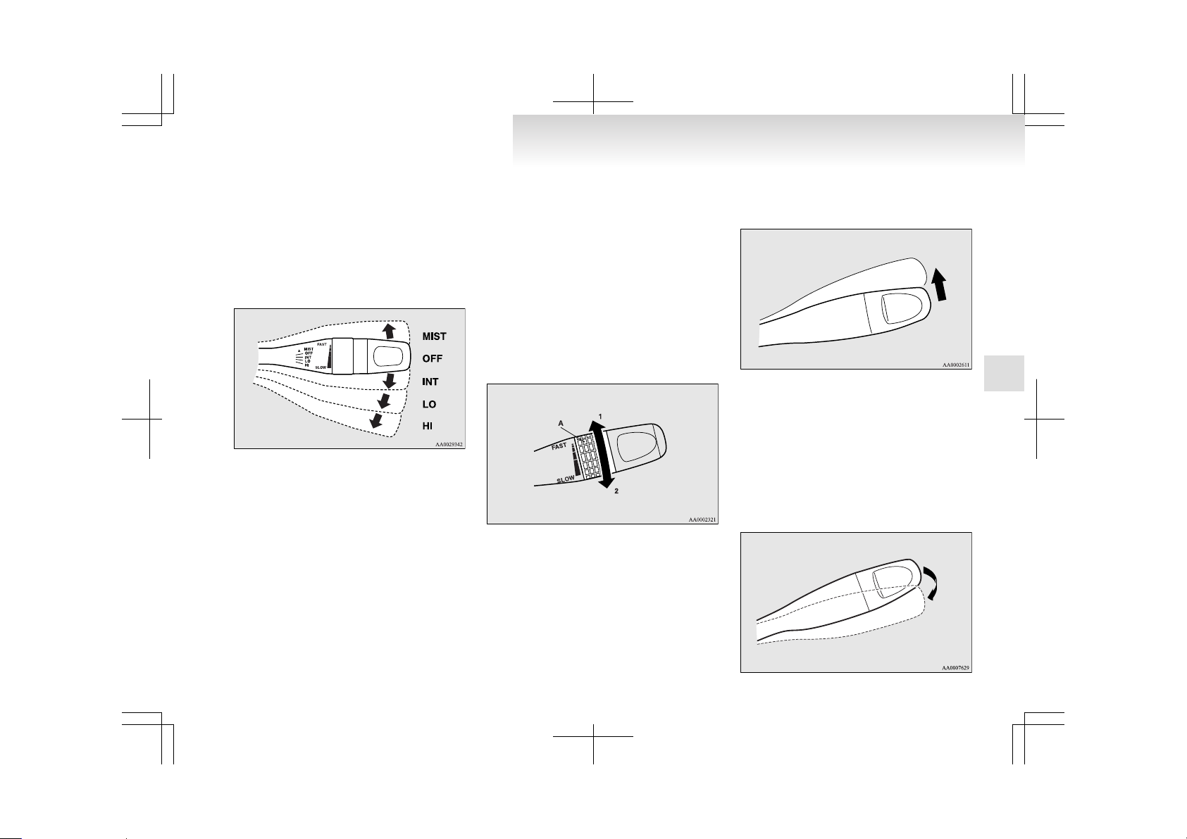
Wiper and washer switch
E00507101162
The windscreen wiper and washer can be operated
with the ignition switch in the “ON” or “ACC” position.
Move the switch to operate the windscreen wipers
or spray the washer fluid.
Windscreen wipers
MIST- Misting function
The wipers will operate once.
OFF- Off
INT- Speed sensitive intermittent operation
The intermittent intervals will change
with the speed of the vehicle.
LO- Slow
HI- Fast
NOTE
l
The speed-sensitive-operation function of the
windscreen wipers can be deactivated.
For further information, we recommend you
to consult a MITSUBISHI MOTORS Authorized Service Point.
On a vehicle equipped with a Multi Display
Station (MDS), the functions can be adjusted
on the screen. Refer to the separate operation
manual for details.
To adjust intermittent intervals
With the lever in the “INT” (speed-sensitive intermittent operation) position, the intermittent intervals can be adjusted by turning the knob (A).
1- Fast
2- Slow
Misting function
Move the lever in the direction of the arrow and release, to operate the wipers once.
Use this function when you are driving in mist or
drizzle.
If the lever is held in the upward position (MIST),
the wipers continue operating until the lever is released.
Windscreen washer
E00507200531
The washer fluid will be sprayed onto the windscreen by pulling the lever towards you. The wipers operate automatically several times while the
washer fluid is being sprayed.
On a vehicle equipped with a headlamp washer, the
headlamp washer operates together with the windscreen washer the first time the windscreen washer
is used if the headlamps are on.
Instruments and controls
3-23
3
 Loading...