

Page 1

MELSEC iQ-F
FX5 User's Manual (Application)
Page 2

Page 3

SAFETY PRECAUTIONS
WARNING
Indicates that incorrect handling may cause hazardous conditions, resulting in
death or severe injury.
CAUTION
Indicates that incorrect handling may cause hazardous conditions, resulting in
minor or moderate injury or property damage.
(Read these precautions before use.)
Before using this product, please read this manual and the relevant manuals introduced in this manual carefully and pay
attention to safety in order to handle the product correctly.
This manual classifies the safety precautions into two categories: [ WARNING] and [ CAUTION].
Depending on the circumstances, procedures indicated by [ CAUTION] may also cause severe injury.
It is important to follow all precautions for personal safety.
Store this manual in a safe place so that it can be read whenever necessary. Always forward it to the end user.
[DESIGN PRECAUTIONS]
WARNING
● Make sure to set up the following safety circuits outside the PLC to ensure safe system operation
even during external power supply problems or PLC failure. Otherwise, malfunctions may cause
serious accidents.
- Most importantly, set up the following: an emergency stop circuit, a protection circuit, an interlock
circuit for opposite movements (such as forward vs. reverse rotation), and an interlock circuit to
prevent damage to the equipment at the upper and lower positioning limits.
- Note that when the CPU module detects an error, such as a watchdog timer error, during self-
diagnosis, all outputs are turned off. Also, when an error that cannot be detected by the CPU
module occurs in an input/output control block, output control may be disabled. External circuits
and mechanisms should be designed to ensure safe machine operation in such a case.
- Note that the output current of the 24 V DC service power supply varies depending on the model
and the absence/presence of extension modules. If an overload occurs, the voltage automatically
drops, inputs in the PLC are disabled, and all outputs are turned off. External circuits and
mechanisms should be designed to ensure safe machine operation in such a case.
- Note that when an error occurs in a relay or transistor of an output circuit, the output might stay on
or off. For output signals that may lead to serious accidents, external circuits and mechanisms
should be designed to ensure safe machine operation.
● Construct an interlock circuit in the program to ensure safe operation for the whole system when
executing control (for data change) of the PLC in operation.
Read the manual thoroughly and ensure complete safety before executing other controls (for program
change, parameter change, forced output and operation status change) of the PLC in operation.
Otherwise, the machine may be damaged and accidents may occur due to erroneous operations.
● In an output circuit, when a load current exceeding the current rating or an overcurrent caused by a
load short-circuit flows for a long time, it may cause smoke and fire. To prevent this, configure an
external safety circuit, such as a fuse.
● For the operating status of each station after a communication failure of the network, refer to relevant
manuals for the network. Incorrect output or malfunction may result in an accident.
1
Page 4

[DESIGN PRECAUTIONS]
CAUTION
● After the CPU module is powered on or is reset, the time taken to enter the RUN status varies
depending on the system configuration, parameter settings, and/or program size.
Design circuits so that the entire system will always operate safely, regardless of this variation in time.
[INSTALLATION PRECAUTIONS]
CAUTION
● Connect the expansion board and expansion adapter securely to their designated connectors. Loose
connections may cause malfunctions.
● Connect the extension cables, peripheral device cables, input/output cables and battery connecting
cable securely to their designated connectors. Loose connections may cause malfunctions.
● When using an SD memory card, insert it into the SD memory card slot. Check that it is inserted
completely. Poor contact may cause malfunction.
● Turn off the power to the PLC before attaching or detaching the following devices. Failure to do so
may cause device failures or malfunctions.
- Peripheral devices, expansion board and expansion adapter
- Extension modules, bus conversion module and connector conversion module
- Battery
[WIRING PRECAUTIONS]
CAUTION
● Do not bundle the power line, control line and communication cables together with or lay them close to
the main circuit, high-voltage line, load line or power line. As a guideline, lay the power line, control
line and connection cables at least 100 mm (3.94") away from the main circuit, high-voltage line, load
line or power line. Noise may cause malfunctions.
2
Page 5

[STARTUP AND MAINTENANCE PRECAUTIONS]
WARNING
● Do not touch any terminal while the PLC's power is on. Doing so may cause electric shock or
malfunctions.
● Before modifying the program in mid-operation, forcing output, running or stopping the PLC, read this
manual and the associated manuals carefully and ensure complete safety. An operation error may
damage the machinery or cause accidents.
● Do not change the program in the PLC from two or more peripheral equipment devices (such as an
engineering tool and a GOT) at the same time. Doing so may cause destruction or malfunction of the
PLC program.
● Use the battery for memory backup in conformance to the FX5 User's Manual (Hardware).
- Use the battery for the specified purpose only.
- Connect the battery correctly.
- Do not charge, disassemble, heat, put in fire, short-circuit, connect reversely, weld, swallow or
burn the battery, or apply excessive force (vibration, impact, drop, etc.) to the battery.
- Do not store or use the battery at high temperatures or expose to direct sunlight.
- Do not expose to water, bring near fire or touch liquid leakage or other contents directly.
Incorrect handling of the battery may cause excessive heat, bursting, ignition, liquid leakage or
deformation, and lead to injury, fire or failures and malfunction of facilities and other equipment.
[PRECAUTIONS IN OPERATION]
CAUTION
● Construct an interlock circuit in the program to ensure safe operation for the whole system when
executing control (for data change) of the PLC in operation. Read the manual thoroughly and ensure
complete safety before executing other controls (for program change, parameter change, forced
output and operation status change) to the PLC in operation. Otherwise, the machine may be
damaged and accidents may occur by erroneous operations.
3
Page 6

INTRODUCTION
This manual contains text, diagrams and explanations which will guide the reader in the correct installation, safe use and
operation of the FX5 Programmable Controllers and should be read and understood before attempting to install or use the
module.
Always forward it to the end user.
Regarding use of this product
• This product has been manufactured as a general-purpose part for general industries, and has not been designed or
manufactured to be incorporated in a device or system used in purposes related to human life.
• Before using the product for special purposes such as nuclear power, electric power, aerospace, medicine or passenger
movement vehicles, consult Mitsubishi Electric.
• This product has been manufactured under strict quality control. However when installing the product where major
accidents or losses could occur if the product fails, install appropriate backup or failsafe functions in the system.
Note
• If in doubt at any stage during the installation of the product, always consult a professional electrical engineer who is
qualified and trained in the local and national standards. If in doubt about the operation or use, please consult the nearest
Mitsubishi Electric representative.
• Since the examples indicated by this manual, technical bulletin, catalog, etc. are used as a reference, please use it after
confirming the function and safety of the equipment and system. Mitsubishi Electric will accept no responsibility for actual
use of the product based on these illustrative examples.
• This manual content, specification etc. may be changed without a notice for improvement.
• The information in this manual has been carefully checked and is believed to be accurate; however, if you notice a doubtful
point, an error, etc., please contact the nearest Mitsubishi Electric representative. When doing so, please provide the
manual number given at the end of this manual.
4
Page 7

MEMO
5
Page 8

CONTENTS
SAFETY PRECAUTIONS . . . . . . . . . . . . . . . . . . . . . . . . . . . . . . . . . . . . . . . . . . . . . . . . . . . . . . . . . . . . . . . . . . . .1
INTRODUCTION. . . . . . . . . . . . . . . . . . . . . . . . . . . . . . . . . . . . . . . . . . . . . . . . . . . . . . . . . . . . . . . . . . . . . . . . . . .4
RELEVANT MANUALS . . . . . . . . . . . . . . . . . . . . . . . . . . . . . . . . . . . . . . . . . . . . . . . . . . . . . . . . . . . . . . . . . . . . .12
TERMS . . . . . . . . . . . . . . . . . . . . . . . . . . . . . . . . . . . . . . . . . . . . . . . . . . . . . . . . . . . . . . . . . . . . . . . . . . . . . . . . .12
PART 1 PROGRAMMING
CHAPTER 1 PROGRAM EXECUTION 16
1.1 Scan Configuration . . . . . . . . . . . . . . . . . . . . . . . . . . . . . . . . . . . . . . . . . . . . . . . . . . . . . . . . . . . . . . . . . . . . . . 16
Initial processing and initialization processing in RUN mode . . . . . . . . . . . . . . . . . . . . . . . . . . . . . . . . . . . . . . . 16
I/O refresh . . . . . . . . . . . . . . . . . . . . . . . . . . . . . . . . . . . . . . . . . . . . . . . . . . . . . . . . . . . . . . . . . . . . . . . . . . . . . . 17
Program operations . . . . . . . . . . . . . . . . . . . . . . . . . . . . . . . . . . . . . . . . . . . . . . . . . . . . . . . . . . . . . . . . . . . . . . . 17
END processing. . . . . . . . . . . . . . . . . . . . . . . . . . . . . . . . . . . . . . . . . . . . . . . . . . . . . . . . . . . . . . . . . . . . . . . . . . 17
1.2 Scan Time. . . . . . . . . . . . . . . . . . . . . . . . . . . . . . . . . . . . . . . . . . . . . . . . . . . . . . . . . . . . . . . . . . . . . . . . . . . . . . 18
Initial scan time . . . . . . . . . . . . . . . . . . . . . . . . . . . . . . . . . . . . . . . . . . . . . . . . . . . . . . . . . . . . . . . . . . . . . . . . . . 18
1.3 Program Execution Sequence . . . . . . . . . . . . . . . . . . . . . . . . . . . . . . . . . . . . . . . . . . . . . . . . . . . . . . . . . . . . . 19
1.4 Execution Type of Program . . . . . . . . . . . . . . . . . . . . . . . . . . . . . . . . . . . . . . . . . . . . . . . . . . . . . . . . . . . . . . . 20
Initial execution type program . . . . . . . . . . . . . . . . . . . . . . . . . . . . . . . . . . . . . . . . . . . . . . . . . . . . . . . . . . . . . . . 20
Scan execution type program . . . . . . . . . . . . . . . . . . . . . . . . . . . . . . . . . . . . . . . . . . . . . . . . . . . . . . . . . . . . . . . 21
Fixed scan execution type program. . . . . . . . . . . . . . . . . . . . . . . . . . . . . . . . . . . . . . . . . . . . . . . . . . . . . . . . . . . 21
Event execution type program . . . . . . . . . . . . . . . . . . . . . . . . . . . . . . . . . . . . . . . . . . . . . . . . . . . . . . . . . . . . . . . 25
Stand-by type program . . . . . . . . . . . . . . . . . . . . . . . . . . . . . . . . . . . . . . . . . . . . . . . . . . . . . . . . . . . . . . . . . . . . 28
1.5 Program Type. . . . . . . . . . . . . . . . . . . . . . . . . . . . . . . . . . . . . . . . . . . . . . . . . . . . . . . . . . . . . . . . . . . . . . . . . . . 29
Subroutine program . . . . . . . . . . . . . . . . . . . . . . . . . . . . . . . . . . . . . . . . . . . . . . . . . . . . . . . . . . . . . . . . . . . . . . . 29
Interrupt program. . . . . . . . . . . . . . . . . . . . . . . . . . . . . . . . . . . . . . . . . . . . . . . . . . . . . . . . . . . . . . . . . . . . . . . . . 30
CHAPTER 2 PROCESSING OF OPERATIONS ACCORDING TO CPU MODULE
OPERATI ON STATUS 35
CHAPTER 3 CPU MODULE MEMORY CONFIGURATION 37
3.1 Memory Configuration . . . . . . . . . . . . . . . . . . . . . . . . . . . . . . . . . . . . . . . . . . . . . . . . . . . . . . . . . . . . . . . . . . . 37
Memory configuration . . . . . . . . . . . . . . . . . . . . . . . . . . . . . . . . . . . . . . . . . . . . . . . . . . . . . . . . . . . . . . . . . . . . . 37
3.2 Files . . . . . . . . . . . . . . . . . . . . . . . . . . . . . . . . . . . . . . . . . . . . . . . . . . . . . . . . . . . . . . . . . . . . . . . . . . . . . . . . . . 39
File type and storage destination memory. . . . . . . . . . . . . . . . . . . . . . . . . . . . . . . . . . . . . . . . . . . . . . . . . . . . . . 39
Executable file operations . . . . . . . . . . . . . . . . . . . . . . . . . . . . . . . . . . . . . . . . . . . . . . . . . . . . . . . . . . . . . . . . . . 39
PART 2 FUNCTIONS
CHAPTER 4 FUNCTION LIST 42
CHAPTER 5 SCAN MONITORING FUNCTION 44
5.1 Scan time monitoring time setting. . . . . . . . . . . . . . . . . . . . . . . . . . . . . . . . . . . . . . . . . . . . . . . . . . . . . . . . . . 44
5.2 Resetting of the watchdog timer . . . . . . . . . . . . . . . . . . . . . . . . . . . . . . . . . . . . . . . . . . . . . . . . . . . . . . . . . . . 44
5.3 Precautions . . . . . . . . . . . . . . . . . . . . . . . . . . . . . . . . . . . . . . . . . . . . . . . . . . . . . . . . . . . . . . . . . . . . . . . . . . . . 44
Watchdog timer reset when executing a program repeatedly . . . . . . . . . . . . . . . . . . . . . . . . . . . . . . . . . . . . . . . 44
Scan time when the WDT instruction is used . . . . . . . . . . . . . . . . . . . . . . . . . . . . . . . . . . . . . . . . . . . . . . . . . . . 45
6
Page 9

CHAPTER 6 CLOCK FUNCTION 46
6.1 Time Setting . . . . . . . . . . . . . . . . . . . . . . . . . . . . . . . . . . . . . . . . . . . . . . . . . . . . . . . . . . . . . . . . . . . . . . . . . . . . 46
Clock data . . . . . . . . . . . . . . . . . . . . . . . . . . . . . . . . . . . . . . . . . . . . . . . . . . . . . . . . . . . . . . . . . . . . . . . . . . . . . . 46
Changing the clock data . . . . . . . . . . . . . . . . . . . . . . . . . . . . . . . . . . . . . . . . . . . . . . . . . . . . . . . . . . . . . . . . . . . 46
Reading clock data . . . . . . . . . . . . . . . . . . . . . . . . . . . . . . . . . . . . . . . . . . . . . . . . . . . . . . . . . . . . . . . . . . . . . . . 47
Precautions . . . . . . . . . . . . . . . . . . . . . . . . . . . . . . . . . . . . . . . . . . . . . . . . . . . . . . . . . . . . . . . . . . . . . . . . . . . . . 47
6.2 Setting Time Zone . . . . . . . . . . . . . . . . . . . . . . . . . . . . . . . . . . . . . . . . . . . . . . . . . . . . . . . . . . . . . . . . . . . . . . . 48
6.3 System clock . . . . . . . . . . . . . . . . . . . . . . . . . . . . . . . . . . . . . . . . . . . . . . . . . . . . . . . . . . . . . . . . . . . . . . . . . . . 49
Special relay used for system clock. . . . . . . . . . . . . . . . . . . . . . . . . . . . . . . . . . . . . . . . . . . . . . . . . . . . . . . . . . . 49
Special register used for system clock . . . . . . . . . . . . . . . . . . . . . . . . . . . . . . . . . . . . . . . . . . . . . . . . . . . . . . . . 49
CHAPTER 7 ONLINE CHANGE 50
7.1 Online Ladder Block Change . . . . . . . . . . . . . . . . . . . . . . . . . . . . . . . . . . . . . . . . . . . . . . . . . . . . . . . . . . . . . . 50
Editable contents . . . . . . . . . . . . . . . . . . . . . . . . . . . . . . . . . . . . . . . . . . . . . . . . . . . . . . . . . . . . . . . . . . . . . . . . . 50
Range changeable in a single session . . . . . . . . . . . . . . . . . . . . . . . . . . . . . . . . . . . . . . . . . . . . . . . . . . . . . . . . 50
Online ladder block change during the boot operation . . . . . . . . . . . . . . . . . . . . . . . . . . . . . . . . . . . . . . . . . . . . 50
Precautions . . . . . . . . . . . . . . . . . . . . . . . . . . . . . . . . . . . . . . . . . . . . . . . . . . . . . . . . . . . . . . . . . . . . . . . . . . . . . 50
CHAPTER 8 INTERRUPT FUNCTION 53
8.1 Multiple Interrupt Function . . . . . . . . . . . . . . . . . . . . . . . . . . . . . . . . . . . . . . . . . . . . . . . . . . . . . . . . . . . . . . . . 53
Interrupt priority . . . . . . . . . . . . . . . . . . . . . . . . . . . . . . . . . . . . . . . . . . . . . . . . . . . . . . . . . . . . . . . . . . . . . . . . . . 53
CONTENTS
CHAPTER 9 PID CONTROL FUNCTION 55
9.1 Outline of Function . . . . . . . . . . . . . . . . . . . . . . . . . . . . . . . . . . . . . . . . . . . . . . . . . . . . . . . . . . . . . . . . . . . . . . 55
9.2 Basic Operation Expressions in PID Instruction . . . . . . . . . . . . . . . . . . . . . . . . . . . . . . . . . . . . . . . . . . . . . . 55
Basic operation expression for PID control . . . . . . . . . . . . . . . . . . . . . . . . . . . . . . . . . . . . . . . . . . . . . . . . . . . . . 55
9.3 How to Use PID Instruction . . . . . . . . . . . . . . . . . . . . . . . . . . . . . . . . . . . . . . . . . . . . . . . . . . . . . . . . . . . . . . . 56
9.4 Relationship Between Parameter Setting and Auto-Tuning . . . . . . . . . . . . . . . . . . . . . . . . . . . . . . . . . . . . . 57
When auto-tuning is not executed (parameter setting) . . . . . . . . . . . . . . . . . . . . . . . . . . . . . . . . . . . . . . . . . . . . 57
When auto-tuning is executed. . . . . . . . . . . . . . . . . . . . . . . . . . . . . . . . . . . . . . . . . . . . . . . . . . . . . . . . . . . . . . . 57
9.5 Parameter . . . . . . . . . . . . . . . . . . . . . . . . . . . . . . . . . . . . . . . . . . . . . . . . . . . . . . . . . . . . . . . . . . . . . . . . . . . . . . 58
9.6 Details of Parameters . . . . . . . . . . . . . . . . . . . . . . . . . . . . . . . . . . . . . . . . . . . . . . . . . . . . . . . . . . . . . . . . . . . . 59
Sampling time (s3). . . . . . . . . . . . . . . . . . . . . . . . . . . . . . . . . . . . . . . . . . . . . . . . . . . . . . . . . . . . . . . . . . . . . . . . 59
Operation setting (S3)+1 . . . . . . . . . . . . . . . . . . . . . . . . . . . . . . . . . . . . . . . . . . . . . . . . . . . . . . . . . . . . . . . . . . . 59
Input filter constant (s3)+2 . . . . . . . . . . . . . . . . . . . . . . . . . . . . . . . . . . . . . . . . . . . . . . . . . . . . . . . . . . . . . . . . . . 61
Proportional gain (s3)+3 . . . . . . . . . . . . . . . . . . . . . . . . . . . . . . . . . . . . . . . . . . . . . . . . . . . . . . . . . . . . . . . . . . . 62
Integral time (s3)+4 . . . . . . . . . . . . . . . . . . . . . . . . . . . . . . . . . . . . . . . . . . . . . . . . . . . . . . . . . . . . . . . . . . . . . . . 63
Differential gain (s3)+5 . . . . . . . . . . . . . . . . . . . . . . . . . . . . . . . . . . . . . . . . . . . . . . . . . . . . . . . . . . . . . . . . . . . . 64
Differential time (s3)+6 . . . . . . . . . . . . . . . . . . . . . . . . . . . . . . . . . . . . . . . . . . . . . . . . . . . . . . . . . . . . . . . . . . . . 65
Alarm output (s3)+24 . . . . . . . . . . . . . . . . . . . . . . . . . . . . . . . . . . . . . . . . . . . . . . . . . . . . . . . . . . . . . . . . . . . . . . 67
9.7 Auto-Tuning . . . . . . . . . . . . . . . . . . . . . . . . . . . . . . . . . . . . . . . . . . . . . . . . . . . . . . . . . . . . . . . . . . . . . . . . . . . . 68
Limit Cycle Method . . . . . . . . . . . . . . . . . . . . . . . . . . . . . . . . . . . . . . . . . . . . . . . . . . . . . . . . . . . . . . . . . . . . . . . 68
Step Response Method . . . . . . . . . . . . . . . . . . . . . . . . . . . . . . . . . . . . . . . . . . . . . . . . . . . . . . . . . . . . . . . . . . . . 71
9.8 Examples of Program . . . . . . . . . . . . . . . . . . . . . . . . . . . . . . . . . . . . . . . . . . . . . . . . . . . . . . . . . . . . . . . . . . . . 73
System configuration example . . . . . . . . . . . . . . . . . . . . . . . . . . . . . . . . . . . . . . . . . . . . . . . . . . . . . . . . . . . . . . 73
Program example 1 . . . . . . . . . . . . . . . . . . . . . . . . . . . . . . . . . . . . . . . . . . . . . . . . . . . . . . . . . . . . . . . . . . . . . . . 74
Program example 2 . . . . . . . . . . . . . . . . . . . . . . . . . . . . . . . . . . . . . . . . . . . . . . . . . . . . . . . . . . . . . . . . . . . . . . . 76
Program example 3 . . . . . . . . . . . . . . . . . . . . . . . . . . . . . . . . . . . . . . . . . . . . . . . . . . . . . . . . . . . . . . . . . . . . . . . 78
Program example 4 . . . . . . . . . . . . . . . . . . . . . . . . . . . . . . . . . . . . . . . . . . . . . . . . . . . . . . . . . . . . . . . . . . . . . . . 80
Program example 5 . . . . . . . . . . . . . . . . . . . . . . . . . . . . . . . . . . . . . . . . . . . . . . . . . . . . . . . . . . . . . . . . . . . . . . . 82
7
Page 10

CHAPTER 10 CONSTANT SCAN 84
10.1 Constant scan settings . . . . . . . . . . . . . . . . . . . . . . . . . . . . . . . . . . . . . . . . . . . . . . . . . . . . . . . . . . . . . . . . . . . 84
CHAPTER 11 REMOTE OPERATION 86
11.1 Remote RUN/STOP . . . . . . . . . . . . . . . . . . . . . . . . . . . . . . . . . . . . . . . . . . . . . . . . . . . . . . . . . . . . . . . . . . . . . . 86
Applications of remote RUN/STOP . . . . . . . . . . . . . . . . . . . . . . . . . . . . . . . . . . . . . . . . . . . . . . . . . . . . . . . . . . . 86
Operation during remote RUN/STOP . . . . . . . . . . . . . . . . . . . . . . . . . . . . . . . . . . . . . . . . . . . . . . . . . . . . . . . . . 86
Method of execution of remote RUN/STOP . . . . . . . . . . . . . . . . . . . . . . . . . . . . . . . . . . . . . . . . . . . . . . . . . . . . 86
11.2 Remote PAUSE . . . . . . . . . . . . . . . . . . . . . . . . . . . . . . . . . . . . . . . . . . . . . . . . . . . . . . . . . . . . . . . . . . . . . . . . . 88
Application of remote PAUSE . . . . . . . . . . . . . . . . . . . . . . . . . . . . . . . . . . . . . . . . . . . . . . . . . . . . . . . . . . . . . . . 88
Method of execution of remote PAUSE. . . . . . . . . . . . . . . . . . . . . . . . . . . . . . . . . . . . . . . . . . . . . . . . . . . . . . . . 88
11.3 Remote RESET . . . . . . . . . . . . . . . . . . . . . . . . . . . . . . . . . . . . . . . . . . . . . . . . . . . . . . . . . . . . . . . . . . . . . . . . . 89
Application of remote RESET . . . . . . . . . . . . . . . . . . . . . . . . . . . . . . . . . . . . . . . . . . . . . . . . . . . . . . . . . . . . . . . 89
Enabling remote RESET . . . . . . . . . . . . . . . . . . . . . . . . . . . . . . . . . . . . . . . . . . . . . . . . . . . . . . . . . . . . . . . . . . . 89
Method of execution of remote RESET . . . . . . . . . . . . . . . . . . . . . . . . . . . . . . . . . . . . . . . . . . . . . . . . . . . . . . . . 90
11.4 Relationship Between Remote Operation and CPU Module . . . . . . . . . . . . . . . . . . . . . . . . . . . . . . . . . . . . .91
CHAPTER 12 DEVICE/LABEL MEMORY AREA SETTING 92
12.1 Default Capacity of Each Area . . . . . . . . . . . . . . . . . . . . . . . . . . . . . . . . . . . . . . . . . . . . . . . . . . . . . . . . . . . . . 92
12.2 The Setting Range of the Capacity of Each Area . . . . . . . . . . . . . . . . . . . . . . . . . . . . . . . . . . . . . . . . . . . . . . 93
12.3 Device/Label Memory Area Setting . . . . . . . . . . . . . . . . . . . . . . . . . . . . . . . . . . . . . . . . . . . . . . . . . . . . . . . . . 94
12.4 Device Setting . . . . . . . . . . . . . . . . . . . . . . . . . . . . . . . . . . . . . . . . . . . . . . . . . . . . . . . . . . . . . . . . . . . . . . . . . . 95
Range of use of device points . . . . . . . . . . . . . . . . . . . . . . . . . . . . . . . . . . . . . . . . . . . . . . . . . . . . . . . . . . . . . . . 96
CHAPTER 13 INITIAL DEVICE VALUE SETTING 97
13.1 Setting Initial Device Values . . . . . . . . . . . . . . . . . . . . . . . . . . . . . . . . . . . . . . . . . . . . . . . . . . . . . . . . . . . . . . . 97
Setting initial device values . . . . . . . . . . . . . . . . . . . . . . . . . . . . . . . . . . . . . . . . . . . . . . . . . . . . . . . . . . . . . . . . . 97
13.2 Applicable Devices . . . . . . . . . . . . . . . . . . . . . . . . . . . . . . . . . . . . . . . . . . . . . . . . . . . . . . . . . . . . . . . . . . . . . . 98
CHAPTER 14 LATCH FUNCTION 99
14.1 Types of Latch . . . . . . . . . . . . . . . . . . . . . . . . . . . . . . . . . . . . . . . . . . . . . . . . . . . . . . . . . . . . . . . . . . . . . . . . . . 99
14.2 Device/label that can be Latched . . . . . . . . . . . . . . . . . . . . . . . . . . . . . . . . . . . . . . . . . . . . . . . . . . . . . . . . . . . 99
14.3 Latch Settings . . . . . . . . . . . . . . . . . . . . . . . . . . . . . . . . . . . . . . . . . . . . . . . . . . . . . . . . . . . . . . . . . . . . . . . . . 100
Latch settings . . . . . . . . . . . . . . . . . . . . . . . . . . . . . . . . . . . . . . . . . . . . . . . . . . . . . . . . . . . . . . . . . . . . . . . . . . 100
Setting latch on labels . . . . . . . . . . . . . . . . . . . . . . . . . . . . . . . . . . . . . . . . . . . . . . . . . . . . . . . . . . . . . . . . . . . . 101
14.4 Clearing of Data of the Latch Range . . . . . . . . . . . . . . . . . . . . . . . . . . . . . . . . . . . . . . . . . . . . . . . . . . . . . . . 101
14.5 Precautions . . . . . . . . . . . . . . . . . . . . . . . . . . . . . . . . . . . . . . . . . . . . . . . . . . . . . . . . . . . . . . . . . . . . . . . . . . . 102
CHAPTER 15 MEMORY CARD FUNCTION 103
15.1 SD Memory Card Forced Stop . . . . . . . . . . . . . . . . . . . . . . . . . . . . . . . . . . . . . . . . . . . . . . . . . . . . . . . . . . . . 103
15.2 Boot Operation . . . . . . . . . . . . . . . . . . . . . . . . . . . . . . . . . . . . . . . . . . . . . . . . . . . . . . . . . . . . . . . . . . . . . . . . 104
CHAPTER 16 DEVICE/LABEL ACCESS SERVICE PROCESSING SETTING 107
CHAPTER 17 RAS FUNCTIONS 109
8
17.1 Self-Diagnostics Function . . . . . . . . . . . . . . . . . . . . . . . . . . . . . . . . . . . . . . . . . . . . . . . . . . . . . . . . . . . . . . . 109
Self-diagnostics timing. . . . . . . . . . . . . . . . . . . . . . . . . . . . . . . . . . . . . . . . . . . . . . . . . . . . . . . . . . . . . . . . . . . . 109
Check method of error. . . . . . . . . . . . . . . . . . . . . . . . . . . . . . . . . . . . . . . . . . . . . . . . . . . . . . . . . . . . . . . . . . . . 109
CPU Module Operation Upon Error Detection Setting . . . . . . . . . . . . . . . . . . . . . . . . . . . . . . . . . . . . . . . . . . . 110
Error Clear . . . . . . . . . . . . . . . . . . . . . . . . . . . . . . . . . . . . . . . . . . . . . . . . . . . . . . . . . . . . . . . . . . . . . . . . . . . . . 112
Page 11

CHAPTER 18 SECURITY FUNCTIONS 113
CHAPTER 19 BUILT-IN I/O FUNCTION 114
19.1 High-speed Counter Function . . . . . . . . . . . . . . . . . . . . . . . . . . . . . . . . . . . . . . . . . . . . . . . . . . . . . . . . . . . . 114
High-speed counter function overview . . . . . . . . . . . . . . . . . . . . . . . . . . . . . . . . . . . . . . . . . . . . . . . . . . . . . . . 114
High-speed counter function execution procedure . . . . . . . . . . . . . . . . . . . . . . . . . . . . . . . . . . . . . . . . . . . . . . 115
High-speed counter specifications. . . . . . . . . . . . . . . . . . . . . . . . . . . . . . . . . . . . . . . . . . . . . . . . . . . . . . . . . . . 115
Assignment for high-speed counters. . . . . . . . . . . . . . . . . . . . . . . . . . . . . . . . . . . . . . . . . . . . . . . . . . . . . . . . . 119
High-speed counter parameters . . . . . . . . . . . . . . . . . . . . . . . . . . . . . . . . . . . . . . . . . . . . . . . . . . . . . . . . . . . . 123
High-speed counter (normal mode). . . . . . . . . . . . . . . . . . . . . . . . . . . . . . . . . . . . . . . . . . . . . . . . . . . . . . . . . . 124
High-speed counter (pulse density measurement mode) . . . . . . . . . . . . . . . . . . . . . . . . . . . . . . . . . . . . . . . . . 126
High-speed counter (rotational speed measurement mode) . . . . . . . . . . . . . . . . . . . . . . . . . . . . . . . . . . . . . . . 129
High-speed comparison table . . . . . . . . . . . . . . . . . . . . . . . . . . . . . . . . . . . . . . . . . . . . . . . . . . . . . . . . . . . . . . 132
Multiple point output, high-speed comparison tables . . . . . . . . . . . . . . . . . . . . . . . . . . . . . . . . . . . . . . . . . . . . 134
Special relay list. . . . . . . . . . . . . . . . . . . . . . . . . . . . . . . . . . . . . . . . . . . . . . . . . . . . . . . . . . . . . . . . . . . . . . . . . 137
Special relay details. . . . . . . . . . . . . . . . . . . . . . . . . . . . . . . . . . . . . . . . . . . . . . . . . . . . . . . . . . . . . . . . . . . . . . 140
Special registers list. . . . . . . . . . . . . . . . . . . . . . . . . . . . . . . . . . . . . . . . . . . . . . . . . . . . . . . . . . . . . . . . . . . . . . 148
Special register details. . . . . . . . . . . . . . . . . . . . . . . . . . . . . . . . . . . . . . . . . . . . . . . . . . . . . . . . . . . . . . . . . . . . 152
Special relays/special registers capable of high-speed transfers with the HCMOV instruction. . . . . . . . . . . . . 161
Precautions when using high-speed counters. . . . . . . . . . . . . . . . . . . . . . . . . . . . . . . . . . . . . . . . . . . . . . . . . . 163
19.2 FX3-compatible high-speed counter function . . . . . . . . . . . . . . . . . . . . . . . . . . . . . . . . . . . . . . . . . . . . . . . 165
FX3-compatible high-speed counter function overview. . . . . . . . . . . . . . . . . . . . . . . . . . . . . . . . . . . . . . . . . . . 165
How to start/stop the high-speed counter using the LC device . . . . . . . . . . . . . . . . . . . . . . . . . . . . . . . . . . . . . 165
The elements of the composition of the LC device . . . . . . . . . . . . . . . . . . . . . . . . . . . . . . . . . . . . . . . . . . . . . . 166
The comparison between the UDCNTF instruction and HIOEN instruction . . . . . . . . . . . . . . . . . . . . . . . . . . . 166
Assignment for FX3-compatible high-speed counters. . . . . . . . . . . . . . . . . . . . . . . . . . . . . . . . . . . . . . . . . . . . 167
FX3-compatible high-speed counter setting . . . . . . . . . . . . . . . . . . . . . . . . . . . . . . . . . . . . . . . . . . . . . . . . . . . 169
FX3-compatible high-speed counter . . . . . . . . . . . . . . . . . . . . . . . . . . . . . . . . . . . . . . . . . . . . . . . . . . . . . . . . . 169
Special relay list. . . . . . . . . . . . . . . . . . . . . . . . . . . . . . . . . . . . . . . . . . . . . . . . . . . . . . . . . . . . . . . . . . . . . . . . . 171
Special relays/LC devices capable of high-speed transfers with the HCMOV instruction. . . . . . . . . . . . . . . . . 172
Precautions when using FX3-compatible high-speed counters. . . . . . . . . . . . . . . . . . . . . . . . . . . . . . . . . . . . . 173
19.3 Pulse Width Measurement Function . . . . . . . . . . . . . . . . . . . . . . . . . . . . . . . . . . . . . . . . . . . . . . . . . . . . . . . 174
Pulse width measurement function overview . . . . . . . . . . . . . . . . . . . . . . . . . . . . . . . . . . . . . . . . . . . . . . . . . . 174
Pulse width measurement specifications. . . . . . . . . . . . . . . . . . . . . . . . . . . . . . . . . . . . . . . . . . . . . . . . . . . . . . 174
Pulse measurement function execution procedure . . . . . . . . . . . . . . . . . . . . . . . . . . . . . . . . . . . . . . . . . . . . . . 175
Pulse width measurement parameters . . . . . . . . . . . . . . . . . . . . . . . . . . . . . . . . . . . . . . . . . . . . . . . . . . . . . . . 176
List of special relays/special registers . . . . . . . . . . . . . . . . . . . . . . . . . . . . . . . . . . . . . . . . . . . . . . . . . . . . . . . . 177
Details of special relays/special registers . . . . . . . . . . . . . . . . . . . . . . . . . . . . . . . . . . . . . . . . . . . . . . . . . . . . . 178
Cautions when using the pulse width measurement function . . . . . . . . . . . . . . . . . . . . . . . . . . . . . . . . . . . . . . 182
Examples of program . . . . . . . . . . . . . . . . . . . . . . . . . . . . . . . . . . . . . . . . . . . . . . . . . . . . . . . . . . . . . . . . . . . . 183
19.4 Pulse Catch Function . . . . . . . . . . . . . . . . . . . . . . . . . . . . . . . . . . . . . . . . . . . . . . . . . . . . . . . . . . . . . . . . . . . 184
Outline of pulse catch function . . . . . . . . . . . . . . . . . . . . . . . . . . . . . . . . . . . . . . . . . . . . . . . . . . . . . . . . . . . . . 184
Specifications of pulse catch function . . . . . . . . . . . . . . . . . . . . . . . . . . . . . . . . . . . . . . . . . . . . . . . . . . . . . . . . 184
Pulse catch function execution procedure. . . . . . . . . . . . . . . . . . . . . . . . . . . . . . . . . . . . . . . . . . . . . . . . . . . . . 184
Pulse catch parameters . . . . . . . . . . . . . . . . . . . . . . . . . . . . . . . . . . . . . . . . . . . . . . . . . . . . . . . . . . . . . . . . . . . 185
Operation of pulse catch function . . . . . . . . . . . . . . . . . . . . . . . . . . . . . . . . . . . . . . . . . . . . . . . . . . . . . . . . . . . 186
Cautions when using the pulse catch function . . . . . . . . . . . . . . . . . . . . . . . . . . . . . . . . . . . . . . . . . . . . . . . . . 187
19.5 FX3-Compatible Pulse Catch Function . . . . . . . . . . . . . . . . . . . . . . . . . . . . . . . . . . . . . . . . . . . . . . . . . . . . . 188
Outline of FX3-compatible pulse catch function . . . . . . . . . . . . . . . . . . . . . . . . . . . . . . . . . . . . . . . . . . . . . . . . 188
Specifications of FX3-compatible pulse catch function . . . . . . . . . . . . . . . . . . . . . . . . . . . . . . . . . . . . . . . . . . . 188
CONTENTS
9
Page 12

FX3-compatible pulse catch function execution procedure . . . . . . . . . . . . . . . . . . . . . . . . . . . . . . . . . . . . . . . . 189
FX3-compatible pulse catch parameters . . . . . . . . . . . . . . . . . . . . . . . . . . . . . . . . . . . . . . . . . . . . . . . . . . . . . . 189
Operation of FX3-compatible pulse catch function . . . . . . . . . . . . . . . . . . . . . . . . . . . . . . . . . . . . . . . . . . . . . . 190
Cautions when using the FX3-compatible pulse catch function . . . . . . . . . . . . . . . . . . . . . . . . . . . . . . . . . . . . 190
19.6 General-purpose Input Functions . . . . . . . . . . . . . . . . . . . . . . . . . . . . . . . . . . . . . . . . . . . . . . . . . . . . . . . . . 191
Outline of general-purpose input functions . . . . . . . . . . . . . . . . . . . . . . . . . . . . . . . . . . . . . . . . . . . . . . . . . . . . 191
Specifications of general-purpose inputs. . . . . . . . . . . . . . . . . . . . . . . . . . . . . . . . . . . . . . . . . . . . . . . . . . . . . . 191
General-purpose input function parameters . . . . . . . . . . . . . . . . . . . . . . . . . . . . . . . . . . . . . . . . . . . . . . . . . . . 192
19.7 PWM Function . . . . . . . . . . . . . . . . . . . . . . . . . . . . . . . . . . . . . . . . . . . . . . . . . . . . . . . . . . . . . . . . . . . . . . . . . 193
Outline of PWM output . . . . . . . . . . . . . . . . . . . . . . . . . . . . . . . . . . . . . . . . . . . . . . . . . . . . . . . . . . . . . . . . . . . 193
PWM output specifications . . . . . . . . . . . . . . . . . . . . . . . . . . . . . . . . . . . . . . . . . . . . . . . . . . . . . . . . . . . . . . . . 193
PWM output function execution procedure . . . . . . . . . . . . . . . . . . . . . . . . . . . . . . . . . . . . . . . . . . . . . . . . . . . . 194
PWM output parameters . . . . . . . . . . . . . . . . . . . . . . . . . . . . . . . . . . . . . . . . . . . . . . . . . . . . . . . . . . . . . . . . . . 195
List of Special relays/special registers. . . . . . . . . . . . . . . . . . . . . . . . . . . . . . . . . . . . . . . . . . . . . . . . . . . . . . . . 196
Details of special relays/special registers . . . . . . . . . . . . . . . . . . . . . . . . . . . . . . . . . . . . . . . . . . . . . . . . . . . . . 196
Cautions when using the PWM function . . . . . . . . . . . . . . . . . . . . . . . . . . . . . . . . . . . . . . . . . . . . . . . . . . . . . . 199
Examples of program . . . . . . . . . . . . . . . . . . . . . . . . . . . . . . . . . . . . . . . . . . . . . . . . . . . . . . . . . . . . . . . . . . . . 199
CHAPTER 20 BUILT-IN ANALOG FUNCTION 201
20.1 Function Outline . . . . . . . . . . . . . . . . . . . . . . . . . . . . . . . . . . . . . . . . . . . . . . . . . . . . . . . . . . . . . . . . . . . . . . . 201
20.2 Analog Input/Output Specifications . . . . . . . . . . . . . . . . . . . . . . . . . . . . . . . . . . . . . . . . . . . . . . . . . . . . . . . 201
Analog input specifications . . . . . . . . . . . . . . . . . . . . . . . . . . . . . . . . . . . . . . . . . . . . . . . . . . . . . . . . . . . . . . . . 201
Analog output specifications . . . . . . . . . . . . . . . . . . . . . . . . . . . . . . . . . . . . . . . . . . . . . . . . . . . . . . . . . . . . . . . 201
List of analog input functions . . . . . . . . . . . . . . . . . . . . . . . . . . . . . . . . . . . . . . . . . . . . . . . . . . . . . . . . . . . . . . . 202
List of analog output functions. . . . . . . . . . . . . . . . . . . . . . . . . . . . . . . . . . . . . . . . . . . . . . . . . . . . . . . . . . . . . . 202
PART 3 DEVICES/LABELS
CHAPTER 21 DEVICES 204
21.1 List of Devices . . . . . . . . . . . . . . . . . . . . . . . . . . . . . . . . . . . . . . . . . . . . . . . . . . . . . . . . . . . . . . . . . . . . . . . . . 204
21.2 User Devices . . . . . . . . . . . . . . . . . . . . . . . . . . . . . . . . . . . . . . . . . . . . . . . . . . . . . . . . . . . . . . . . . . . . . . . . . . 205
Input (X). . . . . . . . . . . . . . . . . . . . . . . . . . . . . . . . . . . . . . . . . . . . . . . . . . . . . . . . . . . . . . . . . . . . . . . . . . . . . . . 205
Output (Y) . . . . . . . . . . . . . . . . . . . . . . . . . . . . . . . . . . . . . . . . . . . . . . . . . . . . . . . . . . . . . . . . . . . . . . . . . . . . . 205
Internal relay (M) . . . . . . . . . . . . . . . . . . . . . . . . . . . . . . . . . . . . . . . . . . . . . . . . . . . . . . . . . . . . . . . . . . . . . . . . 206
Latch relay (L) . . . . . . . . . . . . . . . . . . . . . . . . . . . . . . . . . . . . . . . . . . . . . . . . . . . . . . . . . . . . . . . . . . . . . . . . . . 206
Link relay (B) . . . . . . . . . . . . . . . . . . . . . . . . . . . . . . . . . . . . . . . . . . . . . . . . . . . . . . . . . . . . . . . . . . . . . . . . . . . 206
Annunciator (F) . . . . . . . . . . . . . . . . . . . . . . . . . . . . . . . . . . . . . . . . . . . . . . . . . . . . . . . . . . . . . . . . . . . . . . . . . 206
Link special relay (SB) . . . . . . . . . . . . . . . . . . . . . . . . . . . . . . . . . . . . . . . . . . . . . . . . . . . . . . . . . . . . . . . . . . . . 208
Step relay (S). . . . . . . . . . . . . . . . . . . . . . . . . . . . . . . . . . . . . . . . . . . . . . . . . . . . . . . . . . . . . . . . . . . . . . . . . . . 208
Timer (T/ST) . . . . . . . . . . . . . . . . . . . . . . . . . . . . . . . . . . . . . . . . . . . . . . . . . . . . . . . . . . . . . . . . . . . . . . . . . . . 209
Counter (C/LC) . . . . . . . . . . . . . . . . . . . . . . . . . . . . . . . . . . . . . . . . . . . . . . . . . . . . . . . . . . . . . . . . . . . . . . . . . 212
Data register (D) . . . . . . . . . . . . . . . . . . . . . . . . . . . . . . . . . . . . . . . . . . . . . . . . . . . . . . . . . . . . . . . . . . . . . . . . 215
Link register (W) . . . . . . . . . . . . . . . . . . . . . . . . . . . . . . . . . . . . . . . . . . . . . . . . . . . . . . . . . . . . . . . . . . . . . . . . 215
Link special register (SW) . . . . . . . . . . . . . . . . . . . . . . . . . . . . . . . . . . . . . . . . . . . . . . . . . . . . . . . . . . . . . . . . . 215
21.3 System Devices . . . . . . . . . . . . . . . . . . . . . . . . . . . . . . . . . . . . . . . . . . . . . . . . . . . . . . . . . . . . . . . . . . . . . . . . 215
Special relay (SM) . . . . . . . . . . . . . . . . . . . . . . . . . . . . . . . . . . . . . . . . . . . . . . . . . . . . . . . . . . . . . . . . . . . . . . . 215
Special register (SD) . . . . . . . . . . . . . . . . . . . . . . . . . . . . . . . . . . . . . . . . . . . . . . . . . . . . . . . . . . . . . . . . . . . . . 215
21.4 Module Access Device . . . . . . . . . . . . . . . . . . . . . . . . . . . . . . . . . . . . . . . . . . . . . . . . . . . . . . . . . . . . . . . . . . 216
Specification method . . . . . . . . . . . . . . . . . . . . . . . . . . . . . . . . . . . . . . . . . . . . . . . . . . . . . . . . . . . . . . . . . . . . . 216
Processing speed . . . . . . . . . . . . . . . . . . . . . . . . . . . . . . . . . . . . . . . . . . . . . . . . . . . . . . . . . . . . . . . . . . . . . . . 216
10
Page 13

21.5 Index Registers (Z/LZ). . . . . . . . . . . . . . . . . . . . . . . . . . . . . . . . . . . . . . . . . . . . . . . . . . . . . . . . . . . . . . . . . . . 217
Types of index registers. . . . . . . . . . . . . . . . . . . . . . . . . . . . . . . . . . . . . . . . . . . . . . . . . . . . . . . . . . . . . . . . . . . 217
Index register setting . . . . . . . . . . . . . . . . . . . . . . . . . . . . . . . . . . . . . . . . . . . . . . . . . . . . . . . . . . . . . . . . . . . . . 217
21.6 File Register (R) . . . . . . . . . . . . . . . . . . . . . . . . . . . . . . . . . . . . . . . . . . . . . . . . . . . . . . . . . . . . . . . . . . . . . . . . 218
21.7 Nesting (N) . . . . . . . . . . . . . . . . . . . . . . . . . . . . . . . . . . . . . . . . . . . . . . . . . . . . . . . . . . . . . . . . . . . . . . . . . . . . 218
21.8 Pointer (P) . . . . . . . . . . . . . . . . . . . . . . . . . . . . . . . . . . . . . . . . . . . . . . . . . . . . . . . . . . . . . . . . . . . . . . . . . . . . 219
Global pointers . . . . . . . . . . . . . . . . . . . . . . . . . . . . . . . . . . . . . . . . . . . . . . . . . . . . . . . . . . . . . . . . . . . . . . . . . 219
Label assignment pointers. . . . . . . . . . . . . . . . . . . . . . . . . . . . . . . . . . . . . . . . . . . . . . . . . . . . . . . . . . . . . . . . . 219
21.9 Interrupt Pointer (I) . . . . . . . . . . . . . . . . . . . . . . . . . . . . . . . . . . . . . . . . . . . . . . . . . . . . . . . . . . . . . . . . . . . . . 219
Interrupt causes of the interrupt pointer numbers . . . . . . . . . . . . . . . . . . . . . . . . . . . . . . . . . . . . . . . . . . . . . . . 220
The priority for the interrupt pointer numbers and interrupt factors . . . . . . . . . . . . . . . . . . . . . . . . . . . . . . . . . . 220
21.10 Constant . . . . . . . . . . . . . . . . . . . . . . . . . . . . . . . . . . . . . . . . . . . . . . . . . . . . . . . . . . . . . . . . . . . . . . . . . . . . . . 221
Decimal constant (K) . . . . . . . . . . . . . . . . . . . . . . . . . . . . . . . . . . . . . . . . . . . . . . . . . . . . . . . . . . . . . . . . . . . . . 221
Hexadecimal constant (H) . . . . . . . . . . . . . . . . . . . . . . . . . . . . . . . . . . . . . . . . . . . . . . . . . . . . . . . . . . . . . . . . . 221
Real constant (E). . . . . . . . . . . . . . . . . . . . . . . . . . . . . . . . . . . . . . . . . . . . . . . . . . . . . . . . . . . . . . . . . . . . . . . . 221
Character string constant . . . . . . . . . . . . . . . . . . . . . . . . . . . . . . . . . . . . . . . . . . . . . . . . . . . . . . . . . . . . . . . . . 221
CHAPTER 22 LABELS 222
APPENDIX 224
Appendix 1 Special Relay List . . . . . . . . . . . . . . . . . . . . . . . . . . . . . . . . . . . . . . . . . . . . . . . . . . . . . . . . . . . . . . . . . 224
Appendix 2 Special Register List . . . . . . . . . . . . . . . . . . . . . . . . . . . . . . . . . . . . . . . . . . . . . . . . . . . . . . . . . . . . . . . 240
Appendix 3 Error Code . . . . . . . . . . . . . . . . . . . . . . . . . . . . . . . . . . . . . . . . . . . . . . . . . . . . . . . . . . . . . . . . . . . . . . . 274
Error code system . . . . . . . . . . . . . . . . . . . . . . . . . . . . . . . . . . . . . . . . . . . . . . . . . . . . . . . . . . . . . . . . . . . . . . . 274
Operation when an error occurs . . . . . . . . . . . . . . . . . . . . . . . . . . . . . . . . . . . . . . . . . . . . . . . . . . . . . . . . . . . . 274
How to clear errors . . . . . . . . . . . . . . . . . . . . . . . . . . . . . . . . . . . . . . . . . . . . . . . . . . . . . . . . . . . . . . . . . . . . . . 275
List of error codes . . . . . . . . . . . . . . . . . . . . . . . . . . . . . . . . . . . . . . . . . . . . . . . . . . . . . . . . . . . . . . . . . . . . . . . 275
Appendix 4 Parameter List . . . . . . . . . . . . . . . . . . . . . . . . . . . . . . . . . . . . . . . . . . . . . . . . . . . . . . . . . . . . . . . . . . . . 291
System parameters . . . . . . . . . . . . . . . . . . . . . . . . . . . . . . . . . . . . . . . . . . . . . . . . . . . . . . . . . . . . . . . . . . . . . . 291
CPU parameters . . . . . . . . . . . . . . . . . . . . . . . . . . . . . . . . . . . . . . . . . . . . . . . . . . . . . . . . . . . . . . . . . . . . . . . . 291
Module parameters . . . . . . . . . . . . . . . . . . . . . . . . . . . . . . . . . . . . . . . . . . . . . . . . . . . . . . . . . . . . . . . . . . . . . . 292
Memory card parameters . . . . . . . . . . . . . . . . . . . . . . . . . . . . . . . . . . . . . . . . . . . . . . . . . . . . . . . . . . . . . . . . . 297
CONTENTS
INDEX 298
REVISIONS. . . . . . . . . . . . . . . . . . . . . . . . . . . . . . . . . . . . . . . . . . . . . . . . . . . . . . . . . . . . . . . . . . . . . . . . . . . . .300
WARRANTY . . . . . . . . . . . . . . . . . . . . . . . . . . . . . . . . . . . . . . . . . . . . . . . . . . . . . . . . . . . . . . . . . . . . . . . . . . . .301
TRADEMARKS . . . . . . . . . . . . . . . . . . . . . . . . . . . . . . . . . . . . . . . . . . . . . . . . . . . . . . . . . . . . . . . . . . . . . . . . . .302
11
Page 14

RELEVANT MANUALS
User's manuals for the applicable modules
Manual name <manual number> Description
MELSEC iQ-F FX5 User's Manual (Startup)
<JY997D58201>
MELSEC iQ-F FX5U User's Manual (Hardware)
<JY997D55301>
MELSEC iQ-F FX5UC User's Manual (Hardware)
<JY997D61401>
MELSEC iQ-F FX5 User's Manual (Application)
<JY997D55401> (This manual)
MELSEC iQ-F FX5 Programming Manual (Program Design)
<JY997D55701>
MELSEC iQ-F FX5 Programming Manual (Instructions, Standard
Functions/Function Blocks)
<JY997D55801>
MELSEC iQ-F FX5 User's Manual (Serial Communication)
<JY997D55901>
MELSEC iQ-F FX5 User's Manual (MODBUS Communication)
<JY997D56101>
MELSEC iQ-F FX5 User's Manual (Ethernet Communication)
<JY997D56201>
MELSEC iQ-F FX5 User's Manual (SLMP)
<JY997D56001>
MELSEC iQ-F FX5 User's Manual (Positioning Control)
<JY997D56301>
MELSEC iQ-F FX5 User's Manual (Analog Control)
<JY997D60501>
GX Works3 Operating Manual
<SH-081215ENG>
Performance specifications, procedures before operation, and troubleshooting of the
CPU module.
Describes the details of hardware of the FX5U CPU module, including input/output
specifications, wiring, installation, and maintenance.
Describes the details of hardware of the FX5UC CPU module, including input/output
specifications, wiring, installation, and maintenance.
Describes basic knowledge required for program design, functions of the CPU
module, devices/labels, and parameters.
Describes specifications of ladders, ST, FBD/LD, and other programs and labels.
Describes specifications of instructions and functions that can be used in programs.
Describes N:N network, MELSEC Communication protocol, inverter communication,
non-protocol communication, and predefined protocol support.
Describes MODBUS serial communication.
Describes the functions of the built-in Ethernet port communication function.
Explains methods for the device that is communicating with the CPU module by
SLMP to read and write the data of the CPU module.
Describes the built-in positioning function.
Describes the analog function.
System configuration, parameter settings, and online operations of GX Works3.
TERMS
Unless otherwise specified, this manual uses the following terms.
• indicates a variable portion used to collectively call multiple models or versions.
(Example) FX5U-32MR/ES, FX5U-32MT/ES FX5U-32M/ES
• For details on the FX3 devices that can be connected with the FX5, refer to FX5 User’s Manual (Hardware).
Ter ms Description
■Devices
FX5 Generic term for FX5U and FX5UC PLCs
FX3 Generic term for FX3S, FX3G, FX3GC, FX3U, and FX3UC PLCs
FX5 CPU module Generic term for FX5U CPU module and FX5UC CPU module
FX5U CPU module Generic term for FX5U-32MR/ES, FX5U-32MT/ES, FX5U-32MT/ESS, FX5U-64MR/ES, FX5U-64MT/ES,
FX5UC CPU module Generic term for FX5UC-32MT/D and FX5UC-32MT/DSS
Extension module Generic term for FX5 extension modules and FX3 function modules
• FX5 extension module Generic term for I/O modules, FX5 extension power supply module, and FX5 intelligent function module
• FX3 extension module Generic term for FX3 extension power supply module and FX3 intelligent function module
Extension module (extension cable type) Input modules (extension cable type), Output modules (extension cable type), Bus conversion module
Extension module (extension connector type) Input modules (extension connector type), Output modules (extension connector type), Input/output
I/O module Generic term for input modules, output modules, Input/output modules, and powered input/output modules
Input module Generic term for Input modules (extension cable type) and Input modules (extension connector type)
• Input module (extension cable type) Generic term for FX5-8EX/ES and FX5-16EX/ES
FX5U-64MT/ESS, FX5U-80MR/ES, FX5U-80MT/ES, and FX5U-80MT/ESS
(extension cable type), and Intelligent function modules
modules, Bus conversion module (extension connector type), and Connector conversion module (extension
connector type)
12
Page 15

Term s Description
• Input module (extension connector type) Generic term for FX5-C32EX/D and FX5-C32EX/DS
Output module Generic term for output modules (extension cable type) and output modules (extension connector type)
• Output module (extension cable type) Generic term for FX5-8EYR/ES, FX5-8EYT/ES, FX5-8EYT/ESS, FX5-16EYR/ES, FX5-16EYT/ES, and
FX5-16EYT/ESS
• Output module (extension connector type) Generic term for FX5-C32EYT/D and FX5-C32EYT/DSS
Input/output modules Generic term for FX5-C32ET/D and FX5-C32ET/DSS
Powered input/output module Generic term for FX5-32ER/ES, FX5-32ET/ES, and FX5-32ET/ESS
Extension power supply module Generic term for FX5 extension power supply module and FX3 extension power supply module
• FX5 extension power supply module Different name for FX5-1PSU-5V
• FX3 extension power supply module Different name for FX3U-1PSU-5V
Intelligent module The abbreviation for intelligent function modules
Intelligent function module Generic term for FX5 intelligent function modules and FX3 intelligent function modules
• FX5 intelligent function module Generic term for FX5 intelligent function modules
• FX3 intelligent function module Different name for FX3 special function blocks
Simple motion module Different name for FX5-40SSC-S
Expansion board Generic term for board for FX5U CPU module
• Communication board Generic term for FX5-232-BD, FX5-485-BD, and FX5-422-BD-GOT
Expansion adapter Generic term for adapter for FX5 CPU module
• Communication adapter Generic term for FX5-232ADP and FX5-485ADP
• Analog adapter Generic term for FX5-4AD-ADP and FX5-4DA-ADP
Bus conversion module Generic term for Bus conversion module (extension cable type) and Bus conversion module (extension
connector type)
• Bus conversion module (extension cable
type)
• Bus conversion module (extension connector
type)
Battery Different name for FX3U-32BL
SD memory card Generic term for NZ1MEM-2GBSD, NZ1MEM-4GBSD, L1MEM-2GBSD and L1MEM-4GBSD SD memory
Peripheral device Generic term for engineering tools and GOTs
GOT Generic term for Mitsubishi Graphic Operation Terminal GOT1000 and GOT2000 series
■Software packages
Engineering tool The product name of the software package for the MELSEC programmable controllers
GX Works3 The product name of the software package, SWnDND-GXW3, for the MELSEC programmable controllers
■Manuals
User's manual Generic term for separate manuals
• User's manual (Startup) Abbreviation of MELSEC iQ-F FX5 User's Manual (Startup)
• FX5 User's manual (Hardware) Generic term for MELSEC iQ-F FX5U User's Manual (Hardware) and MELSEC iQ-F FX5UC User's Manual
• FX5U User's manual (Hardware) Abbreviation of MELSEC iQ-F FX5U User's Manual (Hardware)
• FX5UC User's manual (Hardware) Abbreviation of MELSEC iQ-F FX5UC User's Manual (Hardware)
• User's manual (Application) Abbreviation of MELSEC iQ-F FX5 User's Manual (Application)
Programming manual (Program Design) Abbreviation of MELSEC iQ-F FX5 Programming Manual (Program Design)
Programming manual (Instructions, Standard
Functions/Function Blocks)
Communication manual Generic term for MELSEC iQ-F FX5 User's Manual (Serial Communication), MELSEC iQ-F FX5 User's
• Serial communication manual Abbreviation of MELSEC iQ-F FX5 User's Manual (Serial Communication)
• MODBUS communication manual Abbreviation of MELSEC iQ-F FX5 User's Manual (MODBUS Communication)
• Ethernet communication manual Abbreviation of MELSEC iQ-F FX5 User's Manual (Ethernet Communication)
• SLMP manual Abbreviation of MELSEC iQ-F FX5 User's Manual (SLMP)
Positioning manual Abbreviation of MELSEC iQ-F FX5 User's Manual (Positioning Control)
Analog manual Abbreviation of MELSEC iQ-F FX5 User's Manual (Analog Control)
Different name for FX5-CNV-BUS
Different name for FX5-CNV-BUSC
cards
Abbreviation of Secure Digital Memory Card. Device that stores data using flash memory.
(The 'n' represents a version.)
(Hardware)
Abbreviation of MELSEC iQ-F FX5 Programming Manual (Instructions, Standard Functions/Function Blocks)
Manual (MODBUS Communication), MELSEC iQ-F FX5 User's Manual (Ethernet Communication), and
MELSEC iQ-F FX5 User's Manual (SLMP)
13
Page 16

MEMO
14
Page 17

PART 1 PROGRAMMING
This part consists of the following chapters.
1 PROGRAM EXECUTION
2 PROCESSING OF OPERATIONS ACCORDING TO CPU MODULE OPERATION STATUS
3 CPU MODULE MEMORY CONFIGURATION
PART 1
15
Page 18
1 PROGRAM EXECUTION
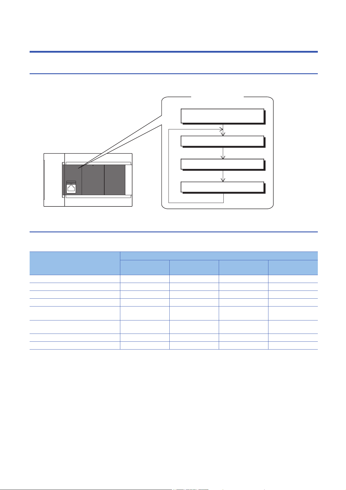
Inside the CPU module
Scan configuration
Program operations
END processing
Initial processing/RUN time
initialization processing
I/O refresh
1.1 Scan Configuration
The configuration of the scan of the CPU module is explained below.
Initial processing and initialization processing in RUN mode
Initial processing according to CPU module status and initialization processing in the RUN status are explained below.
: Execute, : Do not execute
Processing item CPU module status
At power ON At reset STOPRUN after
write to PLC
Initialization of input/output module
Boot from SD memory card
CPU parameter check
System parameter check
Initialization of device/label outside latch range
(bit device: OFF, word device: 0)
Assignment of I/O numbers of input/output
module
Setting of module parameters
Setting of device
*1 Indicates an instance of power OFFON or setting to RUN status without a reset after modifying parameters or program in STOP
status.
*1
At STOPRUN
16
1 PROGRAM EXECUTION
1.1 Scan Configuration
Page 19

I/O refresh
Execute I/O refresh before starting program operations.
• Input ON/OFF data input from input module/intelligent function module to CPU module
• Output ON/OFF data input from CPU module to output module/intelligent function module
When executing constant scan, I/O refresh is executed after the constant scan waiting time ends.
Program operations
Step 0 of each program up to the END/FEND instruction is executed according to program settings. This program is called the
"main routine." Main routine programs can be divided into subroutines. (Page 29 Subroutine program)
END processing
END processing involves the following processes:
• Refreshing of network modules
• Refreshing of intelligent function modules
• Instruction termination processing
• Device/label access service processing
• Resetting of the watchdog timer
• Self-diagnostic processing
• Setting of values to special relays/special registers (set timing: when END processing is executed)
1
1 PROGRAM EXECUTION
1.1 Scan Configuration
17
Page 20
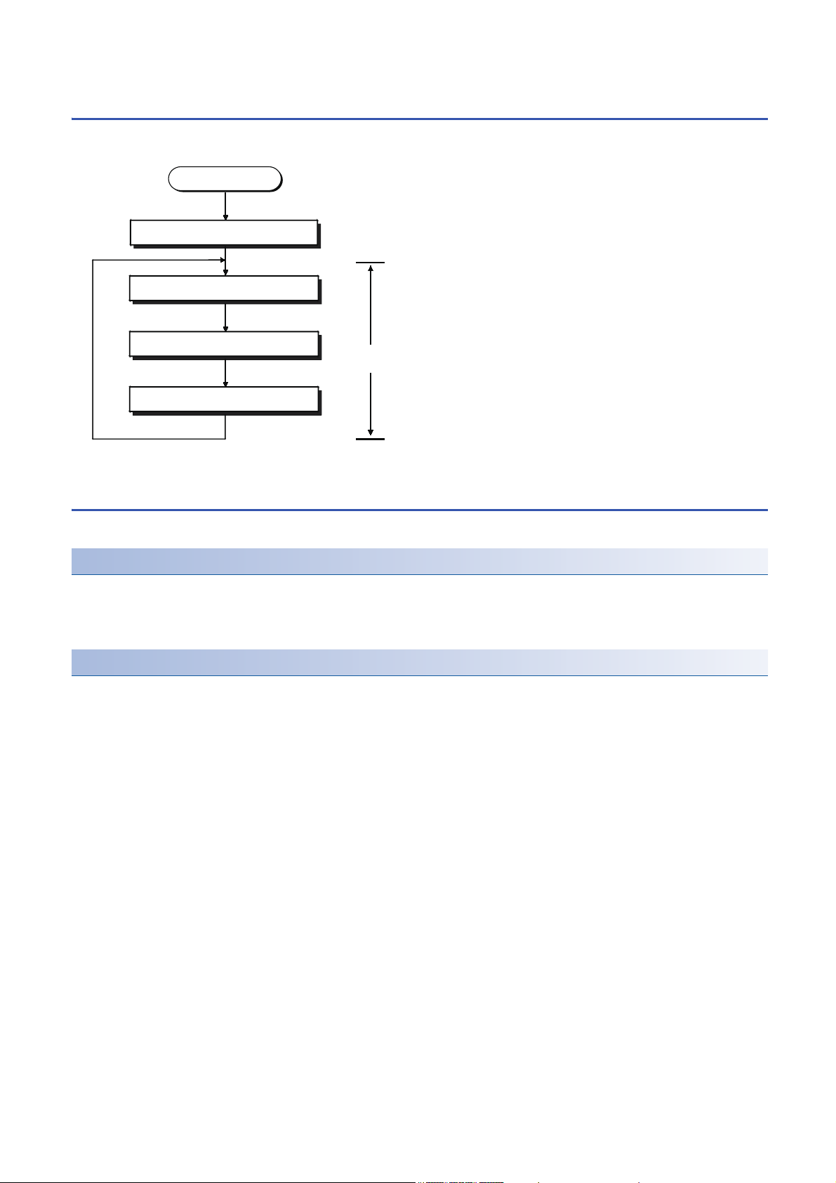
1.2 Scan Time
I/O refresh
Program operations
END processing
RUN time
Scan time
RUN time initialization processing*1
The CPU module repeats the following processing. The scan time is the sum total of each process and execution time.
*1 This process is included in the initial scan time.
Initial scan time
This refers to the initial scan time when the CPU module is in the RUN mode.
How to check the initial scan time
The initial scan time can be checked by the following information:
• Value stored in SD518 (initial scan time (ms)), SD519 (initial scan time (s))
• Program list monitor (GX Works3 Operating Manual)
Monitoring the initial scan time
The initial scan time is monitored by the initial scan time execution monitor time. (5 SCAN MONITORING FUNCTION)
■Initial scan time execution monitor time precautions
• Set an initial execution monitor time longer then the execution time of the initial scan time. An error occurs when the initial
scan time exceeds the set initial execution monitor time.
• The measurement error margin of the initial scan execution monitor time is 10 ms. For example, if the initial execution
monitor time (t) is set to 100 ms, an error occurs in the initial scan time in the range 100 ms < t < 110 ms range.
1 PROGRAM EXECUTION
18
1.2 Scan Time
Page 21
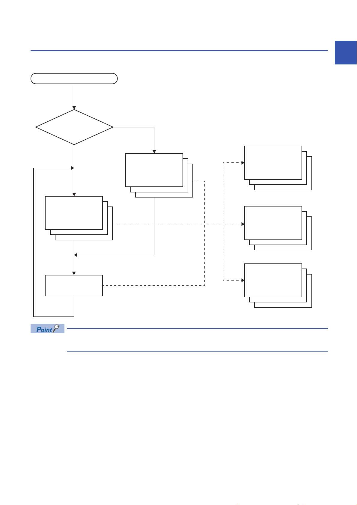
1.3 Program Execution Sequence
STOP/PAUSE→RUN
END processing
Initial execution
type program
Scan execution
type program
Event execution
type program
Fixed scan
execution type
program
Standby type
program
Exists
Does not exist
Does an initial
execution type
program exist?
When the CPU module enters the RUN status, the programs are executed successively according to the execution type of the
programs and execution order setting.
1
When the execution type of the programs is the same, the programs are executed in the order in which the
execution order was set.
1 PROGRAM EXECUTION
1.3 Program Execution Sequence
19
Page 22
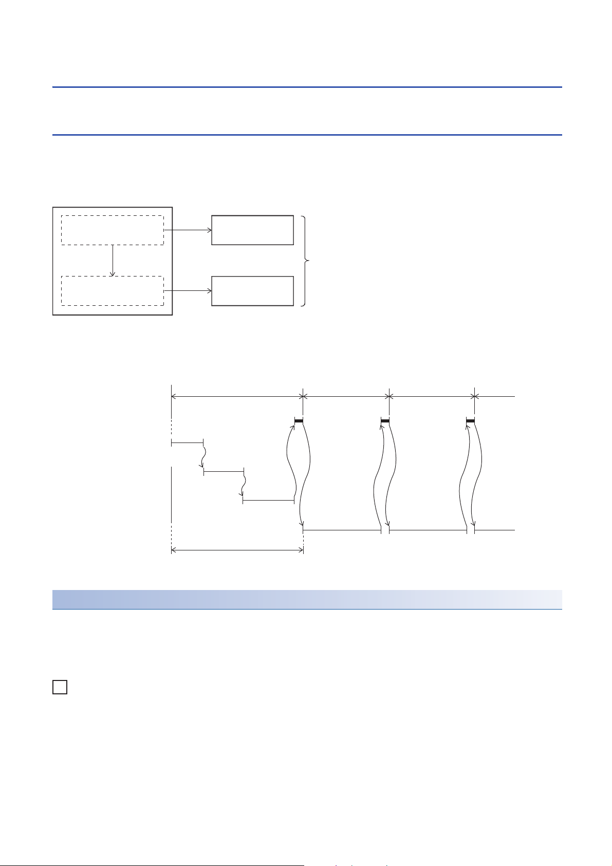
1.4 Execution Type of Program
Ex.
When an initial execution type program is used
Program A
Program B
Control by one program
Initial execution type program
Scan execution
type program
One program can be divided into initial execution
type and scan execution type program.
Processing performed
only once
Processing performed
in every scan
1st scan 2nd scan 3rd scan
STOP/PAUSE→RUN
END processing
Initial execution type program A
Initial execution type program B
Scan execution type program
Initial execution type program C
0 END
0 END
0
0
END
0END 0END
Initial scan time is the sum of the execution time of initial execution type programs
and the END processing time.
Set the program execution conditions.
Initial execution type program
This program type is executed only once when the CPU module changes from the STOP/PAUSE to the RUN status. This
program type is used for programs, that do not need to be executed from the next scan once they are executed, like initial
processing on an intelligent function module.
Also, the execution time of initial execution type programs is the same as the initial scan time.
When multiple initial execution type programs are executed, the execution time of the initial execution type programs
becomes the time until execution of all initial execution type programs is completed.
Precautions
The precautions for initial execution type programs are explained below.
■Restrictions in programming
With initial execution type programs, do not use instructions that require several scans to complete execution (instructions for
which completion devices exist).
e.g. RBFM and WBFM instructions
20
1 PROGRAM EXECUTION
1.4 Execution Type of Program
Page 23
Scan execution type program
1st scan 2nd scan 3rd scan 4th scan
STOP/PAUSE→RUN
END processing
Initial execution type program
Scan execution type program A
Scan execution type program C
Scan execution type program B
Scan time
0 END
0 END
0 END
0 END
0 END
END
0 END
0
Fixed scan interval
END processing
Scan execution type program
Fixed scan execution type program
Condition
established
Condition
established
This program type is executed only once per scan from the scan following the scan where an initial execution type program
was executed.
When multiple scan execution type programs are executed, the execution time of the scan execution type programs becomes
the time until execution of all scan execution type programs is completed. Note, however, that when an program/event
execution type program is executed before a scan execution type program is completed, the execution time of these
programs is included in the scan time.
1
Fixed scan execution type program
An interrupt program which is executed at a specified time interval. Different from the normal interrupt program, this type of
program does not require interrupt pointer (I) and IRET instruction to be written (pointer is assigned by parameter). Execution
is performed by program file basis.
You can use 4 files of fixed scan execution type programs at the maximum.
To execute a fixed scan execution type program, the EI instruction must be used to enable interrupts.
1 PROGRAM EXECUTION
1.4 Execution Type of Program
21
Page 24
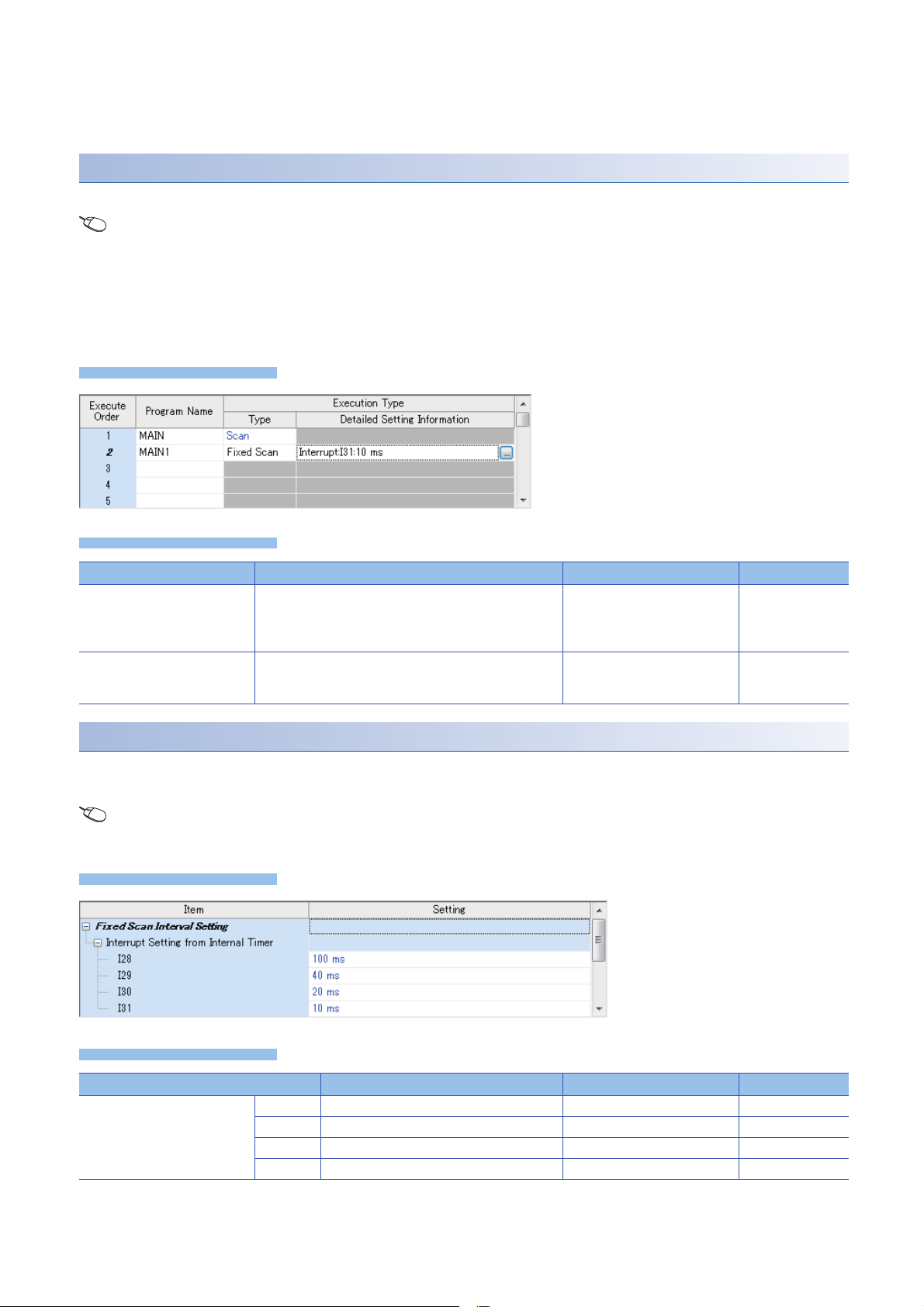
Make the following settings for fixed scan execution type program in CPU parameter.
Window
Displayed items
Window
Displayed items
• Interrupt pointer setting (Interrupt from internal timer: I28 to I31)
• Fixed scan interval setting
Interrupt pointer setting
The interrupt pointer (Interrupt from internal timer: I28 to I31) assigned to a fixed scan execution type program is set up.
Navigation window [Parameter] [FX5UCPU] [CPU Parameter] "Program Setting" "Program Setting"
"Detailed Setting" "Detailed Setting Information"
1. Open program setting screen.
2. Set type as fixed scan.
3. Specify interrupt pointer.
Item Description Setting range Default
Interrupt Pointer Set the interrupt pointer which is assigned to fixed scan
execution type program.
Specified Time Intervals Fixed scan interval setting value is displayed.
Setup is performed on another screen. (Page 22 Fixed
scan interval setting)
•I28
•I29
•I30
•I31
I31
Fixed scan interval setting
Sets the fixed scan interval setting of the fixed scan execution type program. (It is the same as setting for interrupt from
internal timer.)
Navigation window [Parameter] [FX5UCPU] [CPU Parameter] "Interrupt Settings" "Fixed Scan Interval
Setting"
Item Description Setting range Default
Interrupt Setting from Internal
Timer
22
1 PROGRAM EXECUTION
1.4 Execution Type of Program
I28 Sets the execution interval of I28. 1 to 60000 ms (1 ms units) 100 ms
I29 Sets the execution interval of I29. 1 to 60000 ms (1 ms units) 40 ms
I30 Sets the execution interval of I30. 1 to 60000 ms (1 ms units) 20 ms
I31 Sets the execution interval of I31. 1 to 60000 ms (1 ms units) 10 ms
Page 25
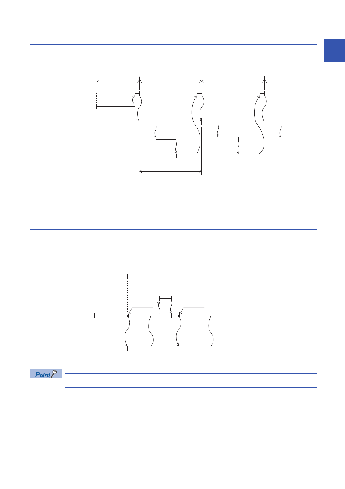
Action when the execution condition is satisfied
Fixed scan interval
END processing
Scan execution type program
Fixed scan execution type program
Condition
established
Constant scan
*1
Waiting time
Performs the following action.
■If the execution condition is satisfied before the interrupt is enabled by the EI instruction
The program enters the waiting status and is executed when the interrupt is enabled. Note that if the execution condition for
this fixed scan execution type program is satisfied more than once during the waiting status, the program is executed only
once when the interrupt is enabled.
■When there are two or more fixed scan execution type programs
When the specified time intervals expire in the same timing, the programs are executed in order according to the priority (I31
> I30 > I29 > I28) of the periodic interrupt pointer.
■If another or the same execution condition is satisfied while the fixed scan execution type
program is being executed
Operates according to the fixed scan execution mode setting.
■If the execution condition is satisfied while the interrupt is disabled by the system
Operates according to the fixed scan execution mode setting.
■When an interrupt is generated during a standby while executing constant scan
Executes the fixed scan execution type program.
1
*1 If processing does not finish during the waiting time, the scan time is extended.
■If another interrupt occurs while the fixed scan execution type program is being executed
If an interrupt program is triggered while the fixed scan execution type program is being executed, the program operates in
accordance with the interrupt priority.
Processing when the fixed scan execution type program starts
The same processing as when the interrupt program starts. (Page 34 Processing at startup of interrupt program)
Fixed scan execution mode
If execution condition for a fixed scan execution type program and fixed cycle interrupt (I28 to I31) based on the internal timer
of the CPU module is satisfied while interruption is disabled, the operation of the program execution after interruption
becomes allowed is specified. However, if execution condition is satisfied while interruption is set to be disabled because of a
DI instruction or the like, this is out of the scope of the fixed scan execution mode.
"Interrupts disabled" refers to the following:
• A program having an interrupt priority higher than or the same as the corresponding program is currently
being executed.
• The corresponding program is currently being executed.
• Program execution is currently at a part in which interrupts are disabled by the system.
1 PROGRAM EXECUTION
1.4 Execution Type of Program
23
Page 26
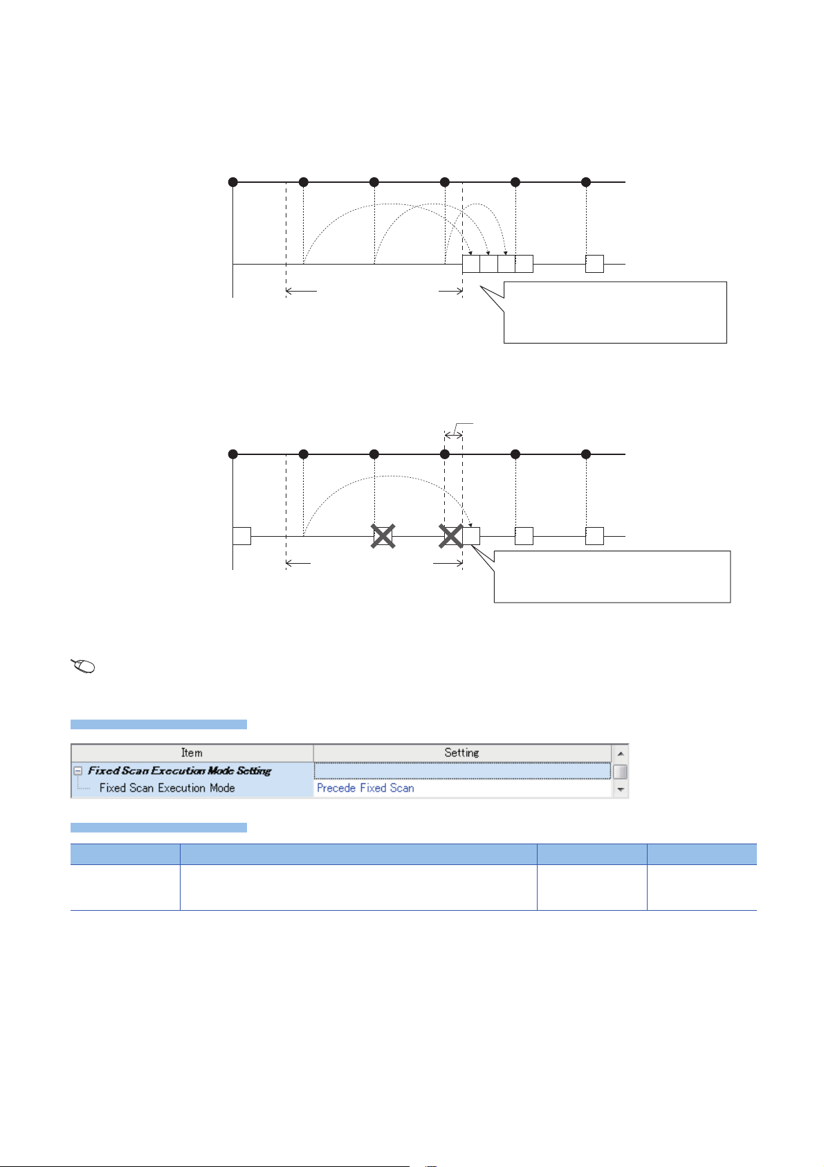
■Operation in the fixed scan execution mode
Window
Displayed items
[1]
Execution condition satisfied:
6 times
Cycle interval of TEISYU
"TEISYU"
(Fixed scan execution type program)
Number of executions:
6 times
All pending executions are executed and the
number of executions of the fixed scan is
guaranteed. (In the chart, three executions are
made immediately after interruption becomes
allowed [1]).
Section where interruptions
are disabled
Section where interruptions
are disabled
Execution condition satisfied:
6 times
Delay behind the cycle
Cycle interval of TEISYU
"TEISYU"
(Fixed scan execution type program)
Number of executions:
4 times
The program is executed once, and the fixed period
execution of the program is maintained. (Even if
execution condition was satisfied twice or more, only
one execution is made.)
This section describes the operation which can be performed in the fixed scan execution mode.
• Execution Count Takes Priority
The program is executed for all the pending number of executions so that it can be executed the same number of times as
execution condition was satisfied.
• Precede Fixed Scan
When the waiting for execution , one execution is made when interrupt becomes allowed. Even if execution condition was
satisfied twice or more, only one execution is performed.
■Fixed scan execution mode setting
Use the fixed scan execution mode setting.
Navigation window [Parameter] [FX5UCPU] [CPU Parameter] "Interrupt Settings" "Fixed Scan Execution
Mode Setting"
Item Description Setting range Default
Fixed Scan Execution
Mode
For Precede Fixed Scan, the periodicity of the program is maintained. For
Execution Count Takes Priority, the program is executed for all pending number
of executions.
• Precede Fixed Scan
• Execution Count
Takes Priority
Precede Fixed Scan
24
1 PROGRAM EXECUTION
1.4 Execution Type of Program
Page 27
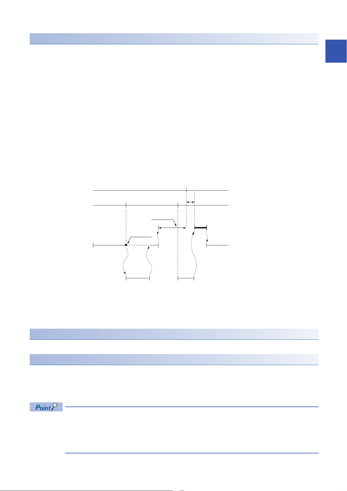
Event execution type program
Y50
M0
10 ms
*1
10 ms
*1
1st scan
I60 interrupt occurs
2nd scan 3rd scan 4th scan 5th scan
STOP/PAUSE→RUN
Scan execution type program A
END processing
Scan execution type program B
Execution order
Y50 turns ON
Event execution type program E
(Executed when 10 ms elapses)
Event execution type program D
(Executed when I60 interrupt occurs)
Event execution type program C
(Executed when Y50 turns ON)
(1)
1st scan
I60 interrupt occurs
2nd scan 3rd scan
STOP/PAUSE→RUN
Scan execution type program A
END processing
Scan execution type program B
Execution order
Event execution type program C
(Executed when I60 interrupt
occurs)
Execution of this program type is triggered by a user-specified event. (Page 25 Trigger type)
*1 Measurement of elapsed time is 10 ms or more because it is determined depending on the scan time.
Trigger type
Triggers for event execution type programs are explained below. (Page 27 Trigger setting)
■Generation of interrupt by interrupt pointer (I)
The program is executed once, immediately, when a specified interrupt cause is generated. An interrupt pointer label can be
appended by adding the FEND instruction to a different program, and the program description partitioned by the IRET
instruction can be turned into an exclusive program.
1
(1) Event execution type program C is executed immediately when the specified event is generated.
• Specifiable interrupt pointer (I)
Specifiable interrupt pointers are I0 to I15, I16 to I23, and I50 to I177.
Execution conditions for the event execution type program which is triggered by interrupt occurred by the
interrupt pointer (I) are the same as those for general interrupt programs. (Page 31 Operation when an
interrupt is generated)
1 PROGRAM EXECUTION
1.4 Execution Type of Program
25
Page 28
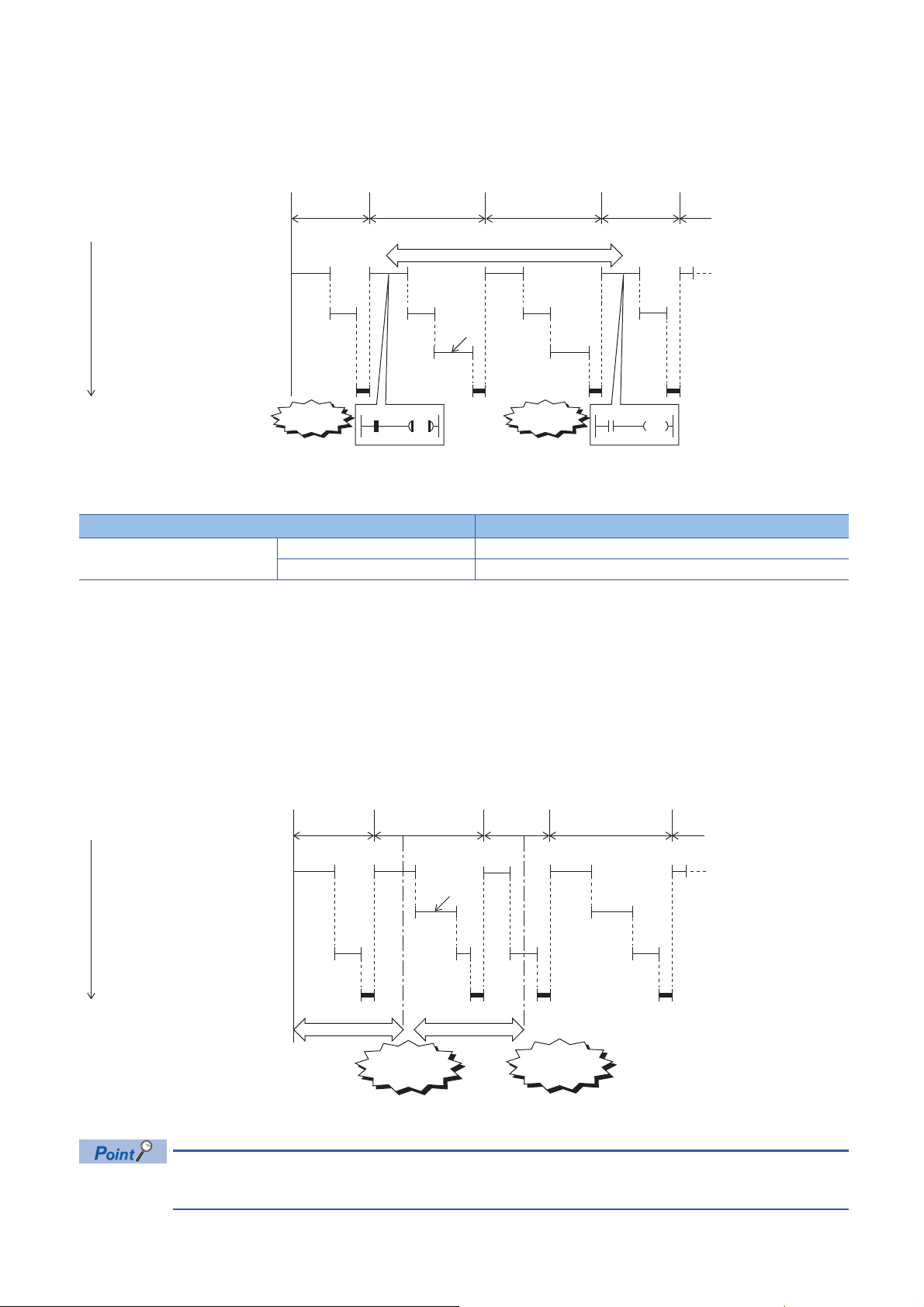
■Bit data ON (TRUE)
Y50
M0
Y50
M0
(1)
1st scan 2nd scan 3rd scan 4th scan
STOP/PAUSE→RUN
Scan execution type program A
END processing
Scan execution type program B
Execution order
Y50 is the ON interval
Y50 turns OFFY50 turns ON
Event execution type program C
(Executed when Y50 turns ON)
10 ms 10 ms
(1)
1st scan 2nd scan 3rd scan 4th scan
STOP/PAUSE→RUN
Scan execution type program A
END processing
Scan execution type program B
Execution order
Measurement interval
Event execution type program C
(Executed when 10 ms elapses)
Specified time 10
ms has passed
Specified time 10
ms has passed
When it is the turn of the corresponding program to be executed, the program is executed if the specified bit data is ON. This
eliminates the need for creating a program for monitoring triggers in a separate program.
(1) The program is executed if Y50 is ON when it is the turn of event execution type program C to be executed.
Applicable devices are as follows.
Item Description
*1
Device
Bit device X (DX), Y, M, L, F, SM, B, SB
Bit specification in word device D, SD, W, SW, R, U\G
*1 Indexed devices cannot be specified.
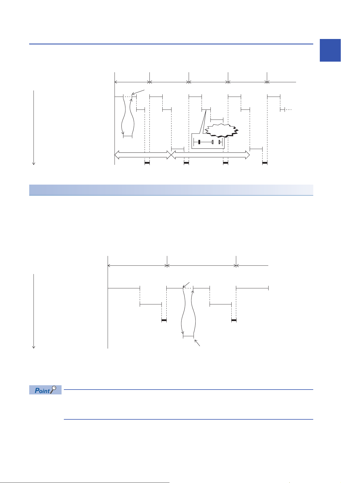
■Elapsed time
The program is executed once when it is the turn of the corresponding program to be executed first after the CPU module is
run and the specified time has elapsed. For second execution onwards, the time is re-calculated from the start of the previous
event execution type program. When it is the turn of the corresponding program to be executed first after specified time has
elapsed, program execution is repeated. Output (Y) currently used in the corresponding program and the current values of
timer (T) can be cleared at the next scan following execution of the corresponding program. This will not be always executing
an interrupt at a constant cycle but can be used when executing a specified program after a specified time has elapsed.
(1) When it is the turn of the first execution after the specified time has elapsed, event execution type program C is executed.
Output and timer current values are not cleared even when the program is set so that output and timer current
values are cleared, if the scan time is longer than the elapsed time set value.
26
1 PROGRAM EXECUTION
1.4 Execution Type of Program
Page 29
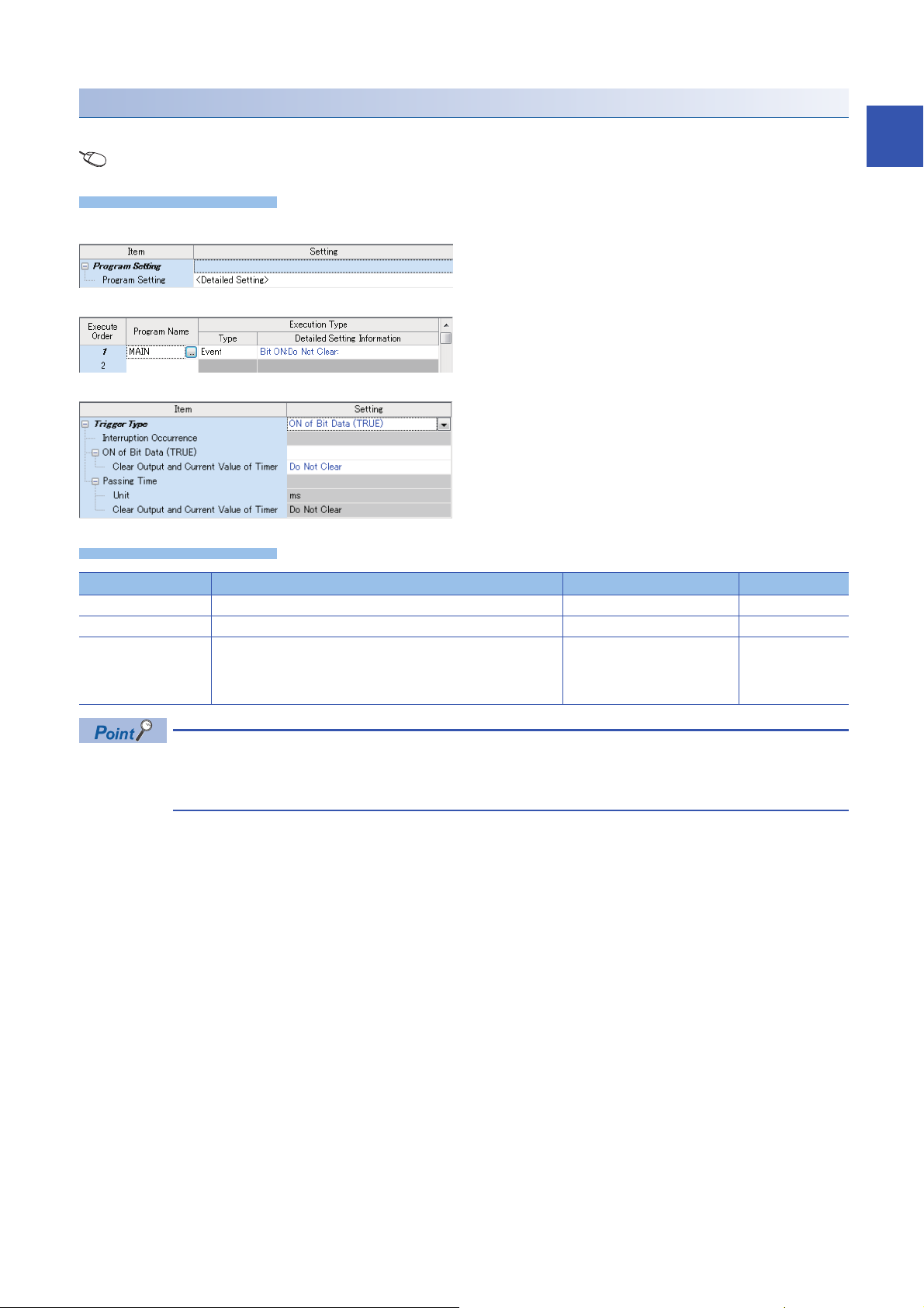
Trigger setting
Operating procedure
Displayed items
Use the event execution type detail setting.
Navigation window [Parameter] [FX5UCPU] [CPU Parameter] "Program Setting"
1
"Program Setting" window
"Detailed Setting" window
1. Click "Detailed Setting" on the Program Setting.
2. Select the program name and set the execution type to
"Event".
3. Click "Detailed Setting Information".
"Event Execution Type Detailed Setting" window
Item Description Setting range Default
Interruption Occurrence Sets the interrupt pointer used as the trigger. I0 to I23, I50 to I177
ON of Bit Data (TRUE) Sets the device used as the trigger. Page 26 Bit data ON (TRUE)
Passing Time Sets the elapsed time. • When "ms" is selected: 1 to
4. Set the trigger type to execute the event execution type
program.
65535 ms (in 1 ms units)
• When "s" is selected: 1 to
65535 s (in 1 s units)
When "Clear Output and Current Value of Timer" is enabled together with "ON of Bit Data (TRUE)" or
"Passing Time", the current values of the output (Y) and timer (T) of this program can be cleared at the first
execution turn of this program that comes after the trigger turns OFF.
1 PROGRAM EXECUTION
1.4 Execution Type of Program
27
Page 30

Stand-by type program
P100
I0
P100
I0
Scan execution type program Scan execution type program
Stand-by type program
Main routine
program
Subroutine
program
Interrupt
program
Main routine
program
Subroutine
program
Interrupt
program
This program is executed only when there is an execution request.
Saving programs in library
Subroutine programs or interrupt programs are saved as standby type programs so that they can be used when controlled
separately from the main routine program. Multiple subroutine programs and interrupt programs can be created in one
standby type program.
How to execute
Execute standby type programs as follows.
• Create sub-routine programs and interrupt programs in the standby type program which is called up by a pointer, etc. or
when an interrupt is generated.
28
1 PROGRAM EXECUTION
1.4 Execution Type of Program
Page 31

1.5 Program Type
RET
END
P1
RET
Y12
RET
Y11
P8
P0
FEND
Y10
Subroutine program 1
Subroutine program 2
Subroutine program 3
Pointer
Main routine program
Programs that use pointers (P) or interrupt pointers (I) are explained below.
Subroutine program
This is the program from pointer (P) up to the RET instruction. Subroutine programs are executed only when they are called
by the CALL instruction. Pointer type labels also can be used instead of pointers (P). The applications of subroutine programs
are as follows:
• By grouping programs that are executed multiple times in one scan into a single subroutine program, the number of steps
in the entire program can be reduced.
• A program that is executed only under certain conditions can be saved as a subroutine program which shortens the scan
time proportionately.
1
Precautions
The precautions when using subroutine programs are explained below.
• Do not use timers (T, ST). Note, however, that timers can be used when a timer coil (OUT T instruction) is always
executed only once in one scan.
• An error occurs when program execution returns to the call source program and the program is terminated without using
the RET instruction.
• An error occurs when there is no pointer (P) or pointer type global label in FB or FUN.
• Subroutine programs can also be managed as separate programs by turning them into standby type
programs. (Page 28 Stand-by type program)
• Pointers need not be programmed starting with the smallest number.
1 PROGRAM EXECUTION
1.5 Program Type
29
Page 32

Interrupt program
I0
I29
Main routine program
I0 interrupt program
I29 interrupt program
Indicates the end of the main routine program.
Interrupt pointer
IRET
IRET
END
FEND
El
Y13
Y12
Y11
Y10
Main routine program
I0 interrupt program
I29 interrupt program
Execution Execution
Execution
Execution
Execution
IRET
IRET
Interrupt
occurs for I0
Interrupt
occurs for I29
Time
This is the program from interrupt pointer (I) up to the IRET instruction.
When an interrupt is generated, the interrupt program corresponding to that interrupt pointer number is executed. Note,
however, that interrupt enabled status must be set with the EI instruction before executing the interrupt program.
• Only one interrupt program can be created with one interrupt pointer number.
• Interrupt pointers need not be programmed starting with the smallest number.
• Interrupt programs can also be managed as separate programs by turning them into standby type
programs. (Page 28 Stand-by type program)
30
1 PROGRAM EXECUTION
1.5 Program Type
Page 33

Operation when an interrupt is generated
Main routine program
Not executed because the interrupt program
execution is in disabled status (DI).
Executed as soon as the interrupt program
execution status changes to enabled.
Interrupt Program
Interrupt occurrence Enable Interrupt (EI)
Execution
Executed as soon as PAUSE → RUN and
the interrupt program execution status
changes to enabled.
Not executed because the CPU module
is in the STOP status.
Interrupt occurrence Enable Interrupt (EI)
Execution
Main routine program
Interrupt Program
PAUSE→ RUN
Main routine program
I0 interrupt program
Enable Interrupt (EI)
Simultaneous occurrence of
multiple interrupt factors
Execution
I10 interrupt program
Execution
Wait status
Wait status
I16 interrupt program
Priority
rank
IRET
IRET
IRET
I0 I10
I16
Execution
Higher
Lower
Operation when an interrupt is generated is explained below.
■If an interrupt cause occurs when interrupt is disabled (DI)
The interrupt that was generated is stored, and the stored interrupt program is executed the moment that the status changes
to interrupt enabled. An interrupt is stored only once even if the same interrupt is generated multiple times. Note, however,
that all interrupts cause are discarded when interrupt disable is specified by the IMASK and SIMASK instructions.
■When an interrupt cause is generated by a PAUSE status
The interrupt program is executed the moment that the CPU module changes to the RUN status and the status changes to
interrupt enabled. An interrupt is stored only once when the same interrupt is generated multiple times before the CPU
module changes to the RUN status.
1
■When multiple interrupts are generated at the same time while in an interrupt enabled status
Interrupt programs are executed in order starting from program having the highest priority. Interrupt programs also run in order
of priority rank when multiple interrupt programs having the same priority are generated simultaneously.
■When an interrupt is generated during standby while executing constant scan
The interrupt program for that interrupt is executed.
■When another interrupt is generated during execution of the interrupt program
If an interrupt such as a fixed scan execution type program (including an interrupt which triggers the event execution type
program) is triggered while an interrupt program is being executed, the program operates in accordance with the interrupt
priority.
1 PROGRAM EXECUTION
1.5 Program Type
31
Page 34

■If an interrupt cause with the same or a lower priority occurs while the interrupt program is
I0
Time
Main routine program
I0 interrupt program
I50 interrupt program
I80 interrupt program
I100 interrupt program
I100 I80 I50 I100 I80 I50
The second interruption cause and later causes
that occur during the execution of an interruption
are not memorized.
After the interruption being
executed is completed, the
interruptions are executed
from I0, which has higher
priority level. I50, which
has higher priority rank, is
executed ahead of I80,
which has the same
priority.
I80 is executed.
(I50 is not executed for
the second time.)
I100 is executed.
(I80 is not executed for
the second time.)
Higher
Lower
Priority
rank
I31
Time
Main routine program
Higher
Lower
I31 interrupt program
*
* The priority is the same.
I29 interrupt program
*
I28 interrupt program
*
I28 I29 I28
When "Execution Count
Takes Priority" is set
When "Precede Fixed
Scan" is set
B
A
I29
TO A
TO B
The second and following interruption causes,
which occur while an interruption is executed,
operate according to the setting of the fixed scan
execution mode.
After the interruption being
executed is completed,
I29, which has higher
priority, is executed.
The second
interruption is
not executed.
The second
interruption
is executed.
The second
interruption is
executed.
Priority
rank
being executed
• For I0 to I23 and I50 to I177
The occurred interrupt cause is memorized, and the interrupt program corresponding to the factor will be executed after the
running interrupt program finishes. Even if the same interrupt factor occurs multiple times, it will be memorized only once.
• For I28 to I31
The interrupt cause that occured is memorized, and the interrupt program corresponding to the cause will be executed after
the running interrupt program finishes. If the same interrupt cause occurs multiple times, it will be memorized once but
operation at the second and later occurrences depends on setting of the fixed scan execution mode. (Page 23 Fixed scan
execution mode)
When "Execution Count Takes Priority" is enabled, the interrupt program corresponding to the memorized interrupt causes will
be executed after the running interrupt program finishes. When "Precede Fixed Scan" is enabled, the second and later
occurrences will not be memorized.
32
1 PROGRAM EXECUTION
1.5 Program Type
Page 35

■If the same interrupt cause occurs while the interrupt program is being executed
Window
Displayed items
I0
Time
Main routine program
I0 interrupt program
I0 I0
The second and following interrupt causes, which
occur while an interruption executed, are not saved.
After the interruption being executed is completed,
the first interrupt program is executed.
I31
Time
Main routine program
I31 interrupt program
I31 I31
When "Execution Count
Takes Priority" is set
When "Precede Fixed Scan" is set
The second and following interruption causes, which occur while an interruption
is executed, operate according to the setting of the fixed scan execution mode.
The second interruption
is not executed.
The second interruption is executed.
• For I0 to I23 and I50 to I177
The interrupt cause that occured is memorized, and the interrupt program corresponding to the cause will be executed after
the running interrupt program finishes. Even if the same interrupt cause occurs multiple times, it will be memorized only once.
• For I28 to I31
The interrupt cause is memorized, and the interrupt program corresponding to the cause will be executed after the running
interrupt program finishes. If the same interrupt factor occurs multiple times, it will be memorized once but operation at the
second and later occurrences depends on setting of the fixed scan execution mode. (Page 23 Fixed scan execution
mode)
When "Execution Count Takes Priority" is enabled, the interrupt program corresponding to the memorized interrupt cause will
be executed after the running interrupt program finishes. When "Precede Fixed Scan" is enabled, the second and later
occurrences will not be memorized.
1
Setting the interrupt cycle
Set the interrupt cycle of interrupts I28 to I31 using the internal timer of the interrupt pointer.
Item Description Setting range Default
Interrupt Setting from Internal
Timer
Navigation window [Parameter] [FX5UCPU] [CPU Parameter] "Interrupt Settings" "Fixed Scan Interval
Setting"
I28 Sets the execution interval of I28. 1 to 60000 ms (1 ms units) 100 ms
I29 Sets the execution interval of I29. 1 to 60000 ms (1 ms units) 40 ms
I30 Sets the execution interval of I30. 1 to 60000 ms (1 ms units) 20 ms
I31 Sets the execution interval of I31. 1 to 60000 ms (1 ms units) 10 ms
1 PROGRAM EXECUTION
1.5 Program Type
33
Page 36

Processing at startup of interrupt program
Processing is as follows when an interrupt program is started up.
• Purge/restore of index registers (Z, LZ)
■Purge/restore of index registers (Z, LZ)
When an interrupt program is started up, the values of the index registers (Z, LZ) in the currently executing program are
purged, and those values are handed over to the interrupt program. Then, when an interrupt program is terminated, the
purged values are restored to the currently executing program.
Precautions
The precautions for interrupt programs are explained below.
■Restrictions in programming
• The PLS/PLF instructions execute OFF processing at the scan following instruction execution. ON devices remain ON until
the interrupt program runs again and the instruction is executed.
• Only a routine timer can be used in an interrupt program. Timers (T, ST) cannot be used.
■Splitting of data
Processing may be interrupted during instruction execution and an interrupt programs can be executed. Accordingly, splitting
of data might occur if the same devices are used by both the interrupt program and the program that is aborted by the
interrupt. Implement the following preventive measure.
• Set instructions that will result in inconsistencies if interrupted to "interrupt disabled" using the DI instruction.
• When using bit data, ensure that the same bit data is not used by both the interrupt program and the program that is
aborted by the interrupt.
■Interrupt precision is not improved
If interrupt precision is not improved, this might be remedied by implementing the following:
• Give higher priority to the interrupt that needs higher precision.
• Use an interrupt pointer with high interrupt priority order.
• Recheck the section of interruption disabled.
34
1 PROGRAM EXECUTION
1.5 Program Type
Page 37

2 PROCESSING OF OPERATIONS ACCORDING
TO CPU MODULE OPERATION STATUS
The CPU module has three operation statuses as follows:
• RUN status
• STOP status
• Paused
Processing of operations on the CPU module in each status is explained below.
Processing of operations in RUN status
In the RUN mode, operations in the sequence program are executed repeatedly in order step 0END (FEND)
instructionstep 0.
■Output when CPU module enters RUN mode
Operation results are output after the sequence program is executed for the duration of one scan.
The device memory other than the output (Y) holds the state immediately before the RUN state. However, if device initial
value is set up, this initial value is set.
■Processing time until start of operation
The processing time from the CPU module switching from STOPRUN up to start of execution of operations in the sequence
program fluctuates according to the system configuration and parameter settings. (Normally, this time is within one second.)
Processing of operations in STOP status
In the STOP status, execution of operations in the sequence program is stopped by the RUN/STOP/RESET switch or a
remote stop. The CPU module also enters the STOP status when a stop error occurs.
2
■Output when CPU module enters STOP status
When the CPU module enters the STOP status, all output points (Y) turn OFF. For device memory other than outputs (Y),
non-latch devices are cleared and latch devices are held.
However, when SM8033 is on and CPU module switches RUNSTOP, it is possible to hold an output state and the current
value of a device.
Processing of operations in paused status
In a paused status, execution of operations in the sequence program is stopped after one scan execution but with outputs and
device memory states held, by a remote pause.
2 PROCESSING OF OPERATIONS ACCORDING TO CPU MODULE OPERATION STATUS
35
Page 38

Processing of operations by the CPU module during switch operations
Processing of operations by the CPU module is as follows according to the RUN or STOP mode.
RUN/STOP status Processing of operations by CPU module
Processing of operations
in sequence program
RUNSTOP The program is executed up to
the END instruction and then
stops.
STOPRUN Program execution starts from
step 0.
The CPU module performs the following processing regardless of RUN or STOP status or paused status.
• Refreshing of input/output modules
• Automatic refreshing of intelligent function modules
• Self-diagnostic processing
• Device/label access service processing
• Setting of values to special relays/special registers (set timing: when END processing is executed)
For this reason, the following operations can be performed even in the STOP status or paused status:
• Monitoring of I/O or test operations by the engineering tool
• Reading/writing from external device using SLMP
• N:N Network
• MODBUS RTU slave
External output Device memory
Other than Y Y
All output points turn OFF. Latch devices are held, and
non-latch devices are cleared.
Operation results are output
after the PLC is run for the
duration of one scan.
The states of device memories
immediately before the CPU
module entered the RUN mode
are held.
Note, however, that when
device initial values are set, the
device initial values are set.
All output points turn OFF.
Operation results are output
after the PLC is run for the
duration of one scan.
36
2 PROCESSING OF OPERATIONS ACCORDING TO CPU MODULE OPERATION STATUS
Page 39

3 CPU MODULE MEMORY CONFIGURATION
3.1 Memory Configuration
CPU module memory is explained below.
Memory configuration
The configuration of CPU module memory is explained below.
Memory type Application
CPU built-in memory Data memory The following files are stored in this memory:
• Program files, FB files
• Restored information files
• Parameter files
• Files that contain device comments, etc.
Device/label memory Data areas for internal devices/labels, etc. are located in this memory.
SD memory card This is for storing files that contain device comments, etc. and folders and files that are created
by SD memory card functions.
Data memory
The following files are stored in data memory.
Category File type Max. number of files Storage area size Remarks
Program Program file 32 1 Mbytes
FB files 16 (Up to 15 for user)
Restored information Restored information files 48 1 Mbytes
Parameters Parameter files common to system 1 1 Mbytes
CPU parameter file 1
Module parameter file 1
Remote password 1
Global label setting file 1
Module extension parameter (for protocol setting) 2
Device initial values file 1
Comments Device comment file 1 2 Mbytes
3
Device/label memory
Device/label memory has the following areas.
Area Storage area size Application
Device/label memory (standard) 96 Kbytes R, W, SW, labels, and latch labels can be placed in this memory in variable lengths.
R and W can be backed up in the event of a power interruption only when the optional battery
is installed. Also, latch label capacity can be increased when the battery is installed.
Device/label memory (fast) 24 Kbytes Bit devices, T, ST, C, LC, D, Z, LZ, labels, and latch labels can be placed in this memory in
variable lengths.
For saving device/label memory 25 Kbytes This memory is for saving latch devices and devices in fast area that require a latch in the
event of a power interruption.
3 CPU MODULE MEMORY CONFIGURATION
3.1 Memory Configuration
37
Page 40

SD memory card
The following files are stored in SD memory card.
Category File type Max. number of files Storage area size Remarks
Program Program file 32 1 Mbytes
FB files 16 (Up to 15 for user)
Restored information Restored information files 48 1 Mbytes
Parameters Parameter files common to system 1 1 Mbytes
CPU parameter file 1
Module parameter file 1
Memory card parameter 1
Remote password 1
Global label setting file 1
Module extension parameter (for protocol setting) 2
Initial device value file 1
Comments Device comment file 1 2 Mbytes
38
3 CPU MODULE MEMORY CONFIGURATION
3.1 Memory Configuration
Page 41

3.2 Files
The CPU module files are explained below.
File type and storage destination memory
File types and their storage destination memory are explained below.
: Can be stored, : Cannot be stored
File type CPU built-in memory SD memory card File name (extension)
Data memory
Drive No.4 Drive No.2
Program Arbitrary.PRG
FB files Arbitrary.PFB
CPU parameters CPU.PRM
System parameters SYSTEM.PRM
Module parameters UNIT.PRM
Memory card parameter MEMCARD.PRM
Device comments Arbitrary.DCM
Device initial values Arbitrary.DID
Global label settings GLBLINF.IFG
Module extension parameter (for protocol setting) UEX3FF01.PPR
UEX3FF00.PPR
Restored information CallTreeInfo.CAB
SourceInfo.CAB
*1
*2
3
*1 For serial communications file.
*2 For Ethernet file.
Executable file operations
File operations that can be executed on each file are explained below. This operation is possible only when the operation
status of the CPU module is the STOP status.
: Can be executed, : No corresponding operation
File type Operation with engineering tool
Write Read Delete
Program
FB files
Parameters
Device comments
Device initial values
Global label setting file
Restored information
3 CPU MODULE MEMORY CONFIGURATION
3.2 Files
39
Page 42

MEMO
40
3 CPU MODULE MEMORY CONFIGURATION
3.2 Files
Page 43

PART 2 FUNCTIONS
This part consists of the following chapters.
4 FUNCTION LIST
5 SCAN MONITORING FUNCTION
6 CLOCK FUNCTION
7 ONLINE CHANGE
8 INTERRUPT FUNCTION
PART 2
9 PID CONTROL FUNCTION
10 CONSTANT SCAN
11 REMOTE OPERATION
12 DEVICE/LABEL MEMORY AREA SETTING
13 INITIAL DEVICE VALUE SETTING
14 LATCH FUNCTION
15 MEMORY CARD FUNCTION
16 DEVICE/LABEL ACCESS SERVICE PROCESSING SETTING
17 RAS FUNCTIONS
18 SECURITY FUNCTIONS
19 BUILT-IN I/O FUNCTION
20 BUILT-IN ANALOG FUNCTION
41
Page 44

4 FUNCTION LIST
The following table lists the functions of the CPU module.
Function Description Reference
Scan monitoring function
(Watchdog timer setting)
Clock function This function is used for the time management in the function which
Online change Changing ladder blocks
while online
Interrupt function Multiple interrupt function When an interrupt occurs while an interrupt program triggered by
PID control function Performs PID control by the PID control instruction. Page 55
Constant scan Keeps the scan time constant and executes program repeatedly. Page 84
Remote operation Remote RUN/STOP Changes the CPU module status to the RUN/STOP/PAUSE status
Remote PAUSE
Remote RESET Resets the CPU module externally while the CPU module is in the
Device/label memory area setting Sets the capacity of each area in the device/label memory. Page 92
Initial device value setting Sets the initial values of devices used in the program directly (not via
Latch function Holds the contents of the device and label of the CPU module when
Memory card function SD memory card forced
stop
Boot operation Transfers the file stored in the SD memory card to the transfer
Device/label access service processing setting Sets the number of execution times of the device/label access
RAS function Self-diagnostics function Self-diagnoses the CPU module to see whether an error exist or not. Page 109
Error clear Batch-clears all the continuation errors being detected.
Security function Protects resources stored in PCs and resources in the units in the
Built-in
input/
output
function
Built-in
analog
function
Built-in Ethernet function A function related to the Ethernet such as the connection with the
Serial communication function A function related to the serial communication such as N:N Network,
High-speed counter function Performs high-speed counter, pulse width measurement, input
Pulse width measurement function
Input interrupt function
Timer interrupt function
High-speed counter interrupt function
Built-in positioning function Executes positioning operation of up to 4 axes by using the
PWM output function Executes a PWM output by using the transistor output of the CPU
Analog input function Two analog inputs and one analog output are built in the FX5U CPU
Analog output function
Detects an error in the hardware and program of the CPU module by
monitoring the scan time.
the system operates such as the date of the error history.
Writes the part of a program edited on the ladder editor using the
engineering tool to the CPU module in units of ladder blocks. Edited
contents spanning multiple portions can be written to the CPU
module at once.
another cause is running, stops the program if its priority is lower
than that of the new interrupt, and runs the higher-priority program
whenever its execution condition is satisfied.
externally while the RUN/STOP/RESET switch of the CPU module is
in RUN status.
STOP status.
the program) to the devices.
the power is turned ON etc.
Makes the SD memory card unavailable without turning OFF the
power even when the function accessing the SD memory card is
executed.
destination memory judged automatically by the CPU module when
the power is turned ON or is reset.
service processing executed by END processing, with parameter.
system of the FX5 from illegal access by a third party such as theft,
alteration, accidental operation and unauthorized execution.
interruption, timer interruption, high-speed counter interruption, etc.
by using the input of the CPU module.
transistor output of the CPU module.
module.
module so that voltage input/voltage output can be performed.
MELSOFT products and GOTs, and socket communication.
MC protocol, inverter communication function and non-protocol
communication.
Page 44
Page 46
Page 50
Page 53
Page 86
Page 97
Page 99
Page 103
Page 107
Page 113
GX Works3 Operating
Manual
Page 114
MELSEC iQ-F FX5 User's
Manual (Positioning
Control)
Page 193
Page 201
MELSEC iQ-F FX5 User's
Manual (Analog Control)
MELSEC iQ-F FX5 User's
Manual (Ethernet
Communication)
MELSEC iQ-F FX5 User's
Manual (Serial
Communication)
42
4 FUNCTION LIST
Page 45

Function Description Reference
MODBUS RTU communication function Connection with the products which support MODBUS RTU is
available. The master and slave functions can be used.
MELSEC iQ-F FX5 User's
Manual (MODBUS
Communication)
4
4 FUNCTION LIST
43
Page 46

5 SCAN MONITORING FUNCTION
Window
Displayed items
FOR K1000
WDT
NEXT
Program repeatedly executed
Resetting of the
watchdog timer
Repeated 1,000 times
M0
This function detects CPU module hardware or program errors by monitoring the scan time. Using the watchdog timer, which
is an internal timer in the CPU module, the following scans are monitored.
• Initial scan (1st scan)
• 2nd scan and after
5.1 Scan time monitoring time setting
Sets the scan time monitoring time.
Navigation window [Parameter] [FX5UCPU] [CPU Parameter] "RAS Setting" "Scan Time Monitoring Time
(WDT) Setting"
Item Description Setting range Default
Initial Scan Sets the scan-time monitoring time (WDT) for the initial scan (first
scan).
After 2nd Scan Sets the scan-time monitoring time (WDT) for the second and later
scans.
10 to 2000 ms (10 ms units) 2000 ms
10 to 2000 ms (10 ms units) 200 ms
5.2 Resetting of the watchdog timer
Resets the watchdog timer when the END/FEND instruction is executed. When the CPU module operates normally and
executes the END/FEND instruction within the watchdog timer setting, the time of the watchdog timer will not time up. If the
END/FEND instruction cannot be executed within the watchdog timer setting due to increased program execution as a result
of hardware error or interrupt in the CPU module, the time of the watchdog timer will time up.
5.3 Precautions
The following precautions relate to the scan monitoring function.
Watchdog timer reset when executing a program repeatedly
The watchdog timer can be reset by executing the WDT instruction in a program. If the time of the watchdog timer is up while
executing a program repeatedly by the FOR instruction and NEXT instruction, use the WDT instruction to reset the watchdog
timer.
44
5 SCAN MONITORING FUNCTION
5.1 Scan time monitoring time setting
Page 47

Scan time when the WDT instruction is used
Internal
processing time
Program
Internal
processing time
Scan execution
program A
Scan execution
program B
WDT reset (CPU module
internal processing)
END
0 ENDWDT
Scan execution
program A
0
Scan time
Clear
WDT measurement time
WDT
measurement
time
Next scan time
Next WDT measurement
time
WDT reset (CPU module
internal processing)
Even though the watchdog timer is reset using the WDT instruction, the scan time value is not reset. The scan timer value is
the value measured up to the END instruction.
5
5 SCAN MONITORING FUNCTION
5.3 Precautions
45
Page 48

6 CLOCK FUNCTION
The CPU module has an internal clock and is used to manage time in functions performed by the system such as dates of the
error history.
6.1 Time Setting
Time operation continues with the large internal capacitor in the CPU module even though the power in the CPU module is
turned OFF or the power failure exceeds the allowable momentary power failure time.
If an optional battery is used, operation continues by the battery.
Clock data
The clock data handled in the CPU unit is described below.
Data name Description
Year 4 digits in calendar year (1980 to 2079)
Month 1 to 12
Day 1 to 31 (Leap year auto detect)
Hour 0 to 23 (24-hour system)
Minute 0 to 59
Second 0 to 59
Day-of-the-week 0: Sunday, 1: Monday, 2: Tuesday, 3: Wednesday, 4: Thursday, 5: Friday, 6: Saturday
Changing the clock data
The clock data can be changed using the following methods.
• Using engineering tools
• Using SM/SD
• Using instructions
Using the engineering tool
Clock data can be changed using Set Clock from the menu. (GX Works3 Operating Manual)
Using SM/SD
The values stored in SD210 (clock data) to SD216 (clock data) are written to the CPU module after END processing execution
of scan when SM210 (clock data set request) is changed from OFFON. If the data from SD210 to SD216 is out of the valid
range, SM211 (clock data set error) is turned ON, the values from SD210 to SD216 are not written in the CPU module.
Writes the SD210 to SD216 clock data to the CPU module.
If the SD210 to SD216 clock data is out of the range
SM210
SM211
ENDEND
ON
OFF
ON
OFF
Using instructions
Writes the clock data to the CPU module, using the TWR(P) instruction. (MELSEC iQ-F FX5 Programming Manual
(Instructions, Standard Functions/Function Blocks))
46
6 CLOCK FUNCTION
6.1 Time Setting
Page 49

Reading clock data
There are the following methods to read clock data.
• Using SM/SD
• Using instructions
Using SM/SD
Clock data is read to SD210 to SD216 when SM213 (clock data read request) is turned ON.
Using instructions
Clock data is read from the CPU module using the TRD(P) instruction. (MELSEC iQ-F FX5 Programming Manual
(Instructions, Standard Functions/Function Blocks))
Precautions
The following describes precautions when setting the time.
When setting the clock for the first time
The clock is not set when the product is shipped.
Correcting the clock data
Before correcting any part of the clock data, you must write all data into the CPU module again.
6
6 CLOCK FUNCTION
6.1 Time Setting
47
Page 50

6.2 Setting Time Zone
Window
Displayed items
The time zone used for the CPU module can be specified. Specifying the time zone enables the clock of the CPU module to
work in the local time zone.
Navigation window [Parameter] [FX5UCPU] [CPU Parameter] "Operation Related Setting" "Clock Related
Setting"
Item Description Setting range Default
Time Zone Sets the time zone used by the CPU module. • UTC+13
•UTC+12
•UTC+11
•UTC+10
•UTC+9:30
•UTC+9
•UTC+8
•UTC+7
•UTC+6:30
•UTC+6
•UTC+5:45
•UTC+5:30
•UTC+5
•UTC+4:30
•UTC+4
•UTC+3:30
•UTC+3
•UTC+2
•UTC+1
•UTC
•UTC-1
•UTC-2
•UTC-3
•UTC-3:30
•UTC-4
•UTC-4:30
•UTC-5
•UTC-6
•UTC-7
•UTC-8
•UTC-9
•UTC-10
•UTC-11
•UTC-12
Comment Enters a comment for the time zone (e.g., name of the city). 1 to 32 letters
UTC+9
48
6 CLOCK FUNCTION
6.2 Setting Time Zone
To reflect the time zone setting on the CPU module, the module must be restarted. If no parameter is set for
the CPU module (factory setting), it operates with "UTC+9".
Page 51

6.3 System clock
There are two types of system clocks, one is to execute ON/OFF by the system and the other is to execute ON/OFF in the
intervals specified by the user.
Special relay used for system clock
Special relays used for system clock are as follows.
Special relay Name
SM400, SM8000 Always ON
SM401, SM8001 Always OFF
SM402, SM8002 After RUN, ON for one scan only
SM403, SM8003 After RUN, OFF for one scan only
SM409, SM8011 0.01 second clock
SM410, SM8012 0.1 second clock
SM411 0.2 second clock
SM412, SM8013 1 second clock
SM413 2 second clock
SM414 2n second clock
SM415 2n ms clock
SM8014 1 min clock
SM420, SM8330 Timing clock output 1
SM421, SM8331 Timing clock output 2
SM422, SM8332 Timing clock output 3
SM423, SM8333 Timing clock output 4
SM424, SM8334 Timing clock output 5
6
Special register used for system clock
Special registers used for system clock are as follows.
Special register Name
SD412 One second counter
SD414 2n second clock setting
SD415 2n ms clock setting
SD420 Scan counter
SD8330 Counted number of scans for timing clock output 1
SD8331 Counted number of scans for timing clock output 2
SD8332 Counted number of scans for timing clock output 3
SD8333 Counted number of scans for timing clock output 4
SD8334 Counted number of scans for timing clock output 5
SM420 to SM424, SM8330 to SM8334, and SD8330 to SD8334 are used by the DUTY instruction.
For the DUTY instruction, refer to the following.
MELSEC iQ-F FX5 Programming Manual (Instructions, Standard Functions/Function Blocks)
6 CLOCK FUNCTION
6.3 System clock
49
Page 52

7 ONLINE CHANGE
This chapter describes online change.
7.1 Online Ladder Block Change
Writes the portion edited on the ladder edit window of the engineering tool to the CPU module in increments of ladders. Edited
contents spanning multiple files or multiple portions can be written to the CPU module at once.
For details on the operating procedure of online ladder block change on engineering tools, refer to the
following.
GX Works3 Operating Manual
Editable contents
Within a program block, instructions and pointers (P, I) can be added, changed, or deleted. Also, as POU unit, program blocks
can be added, changed, or deleted. However, when the program/FB file is not in agreement between engineering tool and a
CPU module, it cannot be added, changed, or deleted.
Range changeable in a single session
The following shows the number of steps and number of ladder blocks which can be changed in a single session.
• Number of ladder blocks in a file: 64 blocks or less (2048 steps or less)
• The total of the changed circuit block count in all files: 256 blocks or less
• The total capacity of the program file and the FB file after a change: 1 M byte or less
Online ladder block change during the boot operation
If online change of ladder block is executed from the SD memory card during boot operation, the corresponding file in the SD
memory card, which is the boot source, can be changed as well.
Precautions
This section describes the precautions on using online ladder block change.
Prohibited operation at online ladder block change
When an online change of ladder block, if the power is turned OFF or a reset is made, the process does not end normally.
Such operation is made, execute rewriting to the PLC.
When deleting OUT instruction which is on
When deleting an OUT instruction (coil) which is not necessary for control, be sure to check that the OUT instruction is off
before deleting it. If the OUT instruction is deleted without turning it off in advance, the output will be retained.
Program file not registered in program setting
A program file which is not registered in parameter setting cannot be written.
Initializing the last execution if the ladder at online ladder block change has an FB call
• If a subroutine type FB is called in a FB definition, the execution information of the previous time in the FB definition of the
subroutine type FB is not initialized.
• If a macro type FB is called in the FB definition of a subroutine type, the execution information of the previous time in the
part equivalent to the macro type FB is not initialized either.
50
7 ONLINE CHANGE
7.1 Online Ladder Block Change
Page 53

Instructions not compatible with online ladder block change
Online change completion
END
1 scan
END END00 0
OFF→OFF
ON
OFF
OFF
OFF
OFF
OFF
OFF
ON
ON
ON
ON
ON
ON→ON
Status of X0
X0
M0
X0
M0
X0
M0
(1)
[ PLS M0 ]
X0
A
A
OFF→ON
Do not execute online change to ladder block including the following instruction.
DSZR instruction, DVIT instruction, TBL instruction, DRVTBL instruction, PLSV instruction, DRVI instruction, DRVA
instruction, DRVMUL instruction, PLSY instruction, PWM instruction, SPD instruction, HIOEN instruction, UDCNTF LC
instruction, ABS instruction, ADPRW instruction, IVCK instruction, IVDR instruction, IVRD instruction, IVWR instruction,
IVBWR instruction, IVMC instruction, S.CPRTCL instruction, SP.CPRTCL instruction, RS2 instruction, SP.SOCOPEN
instruction, SP.SOCCLOSE instruction, SP.SOCSND instruction, SP.SOCRCV instruction, SP.ECPRTCL instruction, RBFM
instruction, WBFM instruction
The cautions at the time of repeatedly performing online change
When online change is performed repeatedly, RUN writing may not be able to be carried out due to insufficient memory in the
CPU module. Please set the CPU module to STOP and write the program.
The operation when a pulse type instruction is included in the range of an online ladder
block change
The operation when a pulse related instruction is included in the range of an online ladder block change is as follows.
Pulse type instruction Description
Rising instruction (PLS and P
instructions)
Falling instruction (PLF and F
instructions)
When a rising instruction exists within the range to be changed, the rising instruction will not be executed if the
execution condition (OFF to ON) is fulfilled at completion of online program change.
When a falling instruction exists within the range to be changed, the falling instruction will not be executed even if the
execution condition (ON to OFF) is fulfilled at completion of online program change.
7
■Rising instruction
When a rising instruction exists within the range to be changed, the rising instruction will not be executed if the execution
condition (OFF to ON) is fulfilled at completion of online program change.
(1) The rising instruction will not be executed even if the execution condition is
OFF to ON.
7 ONLINE CHANGE
7.1 Online Ladder Block Change
51
Page 54

■Falling instruction
Online change completion
END
1 scan
END END00 0
OFF→OFF
ON
OFF
OFF
OFF
OFF
ON
ON
ON
ON→
OFF
Status of X0
X0
M0
X0
M0
(1)
[ PLF M0 ]
X0
A
A
(2)
When a falling instruction exists within the range to be changed, the falling instruction will not be executed even if the
execution condition (ON to OFF) is fulfilled at completion of online program change.
(1) The falling instruction will not be executed even if the execution condition is
OFF to OFF.
(2) If online program change and transition of ON to OFF occur simultaneously,
the falling instruction will not be executed.
52
7 ONLINE CHANGE
7.1 Online Ladder Block Change
Page 55

8 INTERRUPT FUNCTION
• When the multiple interruption function is enabled
I10 interrupt program
I0 interrupt program
Main routine program
Time
(1)
• When not set (at default)
During interruption execution
During interruption stop
I10 interrupt program
I0 interrupt program
Main routine program
Time
(2)
[Priority]
• I10: High
• I0: Low
Interruption occurred
Program stops
Program restarts
This chapter describes the interrupt function.
8.1 Multiple Interrupt Function
When an interrupt occurs while an interrupt program triggered by another cause is running, stops the program if its priority is
lower than that of the new interrupt, and runs the higher-priority program whenever its execution condition is satisfied.
(1) A high-priority interrupt is executed by interrupting a low-priority interrupt.
(2) Even if a high-priority interrupt occurs, it enters the waiting status until the executing interrupt is completed.
Interrupt priority
If the interrupt priority of a program for which its execution condition has been satisfied is higher than that of the running
program, the programs are executed in accordance with their interrupt priority. If the interrupt priority of the new program is the
same or lower, it enters the waiting status until the running program finishes.
8
8 INTERRUPT FUNCTION
8.1 Multiple Interrupt Function
53
Page 56

Interrupt priority setting
Operating procedure
Displayed items
The interrupt priority (1 to 3) of interruptions from modules can be changed.
Navigation window [Parameter] [FX5UCPU] [CPU Parameter] "Interrupt Settings" "Interrupt Priority Setting
from Module"
"Interrupt Settings" window
"Detailed Setting" window
Item Description Setting range Default
Multiple Interrupt Sets whether or not to enable multiple interrupt. • Disable
Interrupt Priority Detailed Setting Sets the priority of the interrupt pointers I0 to I31. 1 to 3
*1 The lower the numerical value, the higher the interrupt priority.
1. Set Multiple Interrupt to "Enable" on the "Interrupt
Settings" window, and click "Detailed Setting".
2. Change the priority of each interrupt pointer.
Disable
• Enable
*1
2
Disabling/enabling interrupts with a specified or lower priority
Interrupts with a priority equal or lower than that specified by the DI or EI instruction can be disabled or enabled even when
multiple interrupts are present.
For details, refer to MELSEC iQ-F FX5 Programming Manual (Instructions, Standard Functions/Function Blocks).
Disabled interrupt priorities and the current interrupt priority can be checked in SD758 (Interrupt disabling for
each priority setting value) and SD757 (Current interrupt priority) respectively.
54
8 INTERRUPT FUNCTION
8.1 Multiple Interrupt Function
Page 57

9 PID CONTROL FUNCTION
CPU module
Target value (SV)
Measured value (PV)
Controlled object
Output value (MV)
PID instruction
ΔMV=KP{(EVn-EVn-1)+
EVn=PVnf-SV
Dn=
MVn=ΣΔMV
TS
TI
TD
TS+KD•TD
KD•TD
TS+KD•TD
EVn+Dn}
(-2PVnf-1+PVnf+PVnf-2)+ •Dn-1
ΔMV=KP{(EVn-EVn-1)+
EVn=SV-PVnf
Dn=
MVn=ΣΔMV
TS
TI
TD
TS+KD•TD
KD•TD
TS+KD•TD
EVn+Dn}
(2PVnf-1-PVnf-PVnf-2)+
•Dn-1
9.1 Outline of Function
PID control is performed by PID control instruction. The PID instruction requires the system to calculate the output (MV) value
from the measured (PV) value. Through combining the P (proportional) action, I (integral) action, and D (derivative) action the
target (SV) value can be obtained.
• Alarm output function
The alarm function can be set for input variation (measured value) or output variation (value).
• Setting limit values
The upper limit and lower limit can be set for the output value.
• Auto-tuning function
The proportional gain (KP), integral time (TI) and differential time (TD) can be set automatically for both the limit cycle method
and step response method.
• Operation method of the PID instruction
Both PID speed type operation and measured value differential type operation are executed.
9
9.2 Basic Operation Expressions in PID Instruction
The PID instruction executes using the speed type or measured value differential type operation expression. According to the
contents of (s3)+1, bit 0 (operation setting (ACT)) specified by (s3) in the PID control, either forward operation or backward
operation is executed. Each value required in the operation is specified by a corresponding parameter (s3) or later.
Basic operation expression for PID control
Operation
setting (ACT)
(s3+1: b0)
Forward operation
(OFF)
Backward operation
(ON)
Operation expression The meaning of the signs
EVn: Deviation in sampling at this time
EVn-1: Deviation in previous cycle
SV: Target value
PVnf: Measured value in sampling at this time
(after filter)
PVnf-1: Measured value in previous cycle
(after filter)
PVnf-2: Measured value in two cycles before
(after filter)
MV: Output variation
MVn: Operation quantity at this time
Dn: Differential term at this time
Dn-1: Differential term in previous cycle
TS: Sampling cycle
KP: Proportional gain
TI: Integral constant
TD: Differential constant
KD: Differential gain
9 PID CONTROL FUNCTION
9.1 Outline of Function
55
Page 58

Expression for calculating the measured value (after the filter) in sampling at this time
Setting data
Processing details
(s1) (s2) (s3) (d)
EN ENO
ds1
s2
s3
Command input
Target value (SV)
Measured value (PV)
Parameters
Output value (MV)
PID (s1) (s2) (s3) (d)
(PVnf)
The value "PVnf" is obtained from the following expression based on the read measured value.
Measured value after filter: PVnf = PVn+L (PVnf-1-PVn)
PVn: Measured value in sampling at this time
L: Filter coefficient
PVnf-1: Measured value in previous cycle (after filter)
9.3 How to Use PID Instruction
This instruction executes PID control which changes the output value according to the input variation.
For details on the PID instruction, refer to the following manual.
MELSEC iQ-F FX5 Programming Manual (Instructions, Standard Functions/Function Blocks)
Ladder diagram Structured text
ENO:=PID(EN,s1,s2,s3,d);
FBD/LD
■Descriptions, ranges, and data types
Operand Description Range Data type Data type (label)
(s1) Device number storing the target value (SV) -32768 to +32767 16-bit signed binary ANY16
(s2) Device number storing the measured value (PV) -32768 to +32767 16-bit signed binary ANY16
(s3) Device number storing PID parameters 1 to 32767 16-bit signed binary ANY16
(d) Device number storing the output value (MV) -32768 to +32767 16-bit signed binary ANY16
■Applicable devices
Operand Bit Word Double word Indirect
X, Y, M, L, SM,
F, B, SB, S
(s1) *1
(s2)
(s3)
(d)
*1 Only D, SD, R can be used.
U\G T, ST,
C, LC
T, ST, C, D,
W, SD, SW, R
*1
*1
*1
U\G Z LC LZ K, H E $
specification
• Once the target value (s1), measured value (s2) and PID parameters (s3) to (s3)+6 are set and the program is executed,
the operation result (MV) is transferred to the output value (d) at every sampling time. The sampling time is specified by
(s3)
Constant Others
56
9 PID CONTROL FUNCTION
9.3 How to Use PID Instruction
Page 59

■Set item
Set item Description Occupie
d points
(s1) Target value
(SV)
(s2) Measured value
(PV)
(s3) Parameter PID control
(d) Output value
(MV)
The target value (SV) is set.
The PID instruction does not change the settings.
[Caution on using the auto-tuning (limit cycle method)]
If the target value for auto-tuning is different from the target value in the PID control, it is necessary to set a value
to which a bias value is added, and then store the actual target value when the auto-tuning flag turns OFF.
This is the input value of the PID operation.
It is necessary to read a normal measurement data before the execution of the PID operation for the measurement
value of PID (PV). If an input value from an analog input is used for the PID operation, use caution to its conversion
time.
25 devices are occupied from the head device specified in (s3)
Auto-tuning: In the limit cycle (1)
29 devices are occupied from the head device specified in (s3)
Auto-tuning: In the step response method (2)
25 devices are occupied from the head device specified in (s3)
PID control (normal processing)
The user sets the initial output value before driving the instruction. After that, the operation result is stored.
Auto-tuning: In the limit cycle
The Upper Limit Value (ULV) or Lower Limit Value (LLV) value is automatically output during auto-tuning. The
specified MV value is output when auto-tuning is finished.
Auto-tuning: In the step response method
The user sets the step output value before driving the instruction. The MV value is not changed by PID instruction
during auto-tuning.
1 point
1 point
25 points
29 points
25 points
1 point
9
■Precautions for using the PID instruction
For the precautions for using the PID instruction, refer to the following manual.
MELSEC iQ-F FX5 Programming Manual (Instructions, Standard Functions/Function Blocks)
9.4 Relationship Between Parameter Setting and
Auto-Tuning
When auto-tuning is not executed (parameter setting)
It is necessary to write the set value of the parameters (s3) to (s3)+6 using MOV instruction in advance, etc. before starting
the PID operation when auto-tuning is not executed. If a device with a latch setting is specified, the setting data is retained
even after the power to the CPU module is turned OFF; therefore, the writing at the 2nd power ON is not required.
For details on parameters, refer to Page 58 Parameter.
When auto-tuning is executed
The proportional gain ((s3)+3), integral time ((s3)+4) and differential time ((s3)+6) are important constants for executing the
auto-tuning function described later and for optimizing the PID control. These constants can be set automatically.
For a detailed description of auto-tuning, refer to Page 68 Auto-Tuning.
9 PID CONTROL FUNCTION
9.4 Relationship Between Parameter Setting and Auto-Tuning
57
Page 60

9.5 Parameter
Set item Description/Setting range Remarks
(s3) Sampling time (TS) 1 to 32767 (ms) It cannot be shorter than operation cycle of the PLC.
(s3)+1 Operation setting
(ACT)
(s3)+2 Input filter constant () 0 to 99 [%] When "0" is set, input filter is not provided.
(s3)+3 Proportional gain (KP) 1 to 32767 [%]
(s3)+4 Integral time (TI) 0 to 32767 [100 ms] When "0" is set, it is handled as "" (no integration).
(s3)+5 Differential gain (KD) 0 to 100 [%] When "0" is set, differential gain is not provided.
(s3)+6 Differential time (TD) 0 to 32767 [10 ms] When "0" is set, differential is not executed.
(s3)+7 to
(s3)+19
(s3)+20
(s3)+21
(s3)+22
(s3)+23
(s3)+24
(s3)+25 PV value threshold
(s3)+26 Output value upper limit (ULV) Set maximum value (ULV) of output value (MV).
(s3)+27 Output value lower limit (LLV) Set minimum value (LLV) of output value (MV).
(s3)+28 Wait setting from end of tuning
These devices are occupied for internal processing of PID operation. Do not change data.
*1
Input variation (incremental)
alarm set value
*1
Input variation (decremental)
alarm set value
*1
Output variation (incremental)
alarm set value
Output upper limit set value -32768 to +32767 It is valid when operation setting (ACT) (b2 of (s3)+1) is
*1
Output variation (decremental)
alarm set value
Output lower limit set value -32768 to +32767 It is valid when operation setting (ACT) (b2 of (s3)+1) is
*1
Alarm output b0 0: Input variation (incremental) is not exceeded.
(hysteresis) width (SHPV)
cycle to start of PID control
(KW)
*1 (s3)+20 to +24 become used only if b1, b2, or b5 are set to "1" to determine the action (ACT) (s3) of +1.
b0 0: Forward operation
1: Backward operation
b1 0: Input variation alarm is invalid
1: Input variation alarm is valid
b2 0: Output variation alarm is invalid
1: Output variation alarm is valid
b3 Not used
b4 0: Auto-tuning is not executed.
1: Auto-tuning is executed
b5 0: Upper and lower limits of output value are not
valid
1: Upper and lower limits of output value are valid
b6 0: Step response method
1: Limit cycle method
b7 to b15 Not used
0 to 32767 It is valid when operation setting (ACT) (b1 of (s3)+1) is
0 to 32767 It is valid when operation setting (ACT) (b1 of (s3)+1) is
0 to 32767 It is valid when operation setting (ACT) (b2 of (s3)+1) is
0 to 32767 It is valid when operation setting (ACT) (b2 of (s3)+1) is
1: Input variation (incremental) is exceeded.
b1 0: Input variation (decremental) is not exceeded.
1: Input variation (decremental) is exceeded.
b2 0: Output variation (incremental) is not exceeded.
1: Output variation (incremental) is exceeded.
b3 0: Output variation (decremental) is not exceeded.
1: Output variation (decremental) is exceeded.
Set it according to measured value (PV)
fluctuation.
-50 to +32717 [%]
Operation direction
Do not set b2 and b5 to ON at the same time.
Do not set b2 and b5 to ON at the same time.
Select auto-tuning mode.
"1".
"1".
"1" and (ACT) (b5 of (s3)+1) is "0".
"0" and (ACT) (b5 of (s3)+1) is "1".
"1" and (ACT) (b5 of (s3)+1) is "0".
"0" and (ACT) (b5 of (s3)+1) is "1".
It is valid when operation setting (ACT) (b1 or b2 of
(s3)+1) is "1".
The setting below is required when the limit cycle method
is used (when the operation setting (ACT) b6 is set to
ON).
58
9 PID CONTROL FUNCTION
9.5 Parameter
Page 61

9.6 Details of Parameters
Temperature
Measured value (PV)
Time
Target value (SV)
This chapter describes the details of parameters.
Sampling time (s3)
Set the cycle time (ms) for the PID operation. Setting range: 1 to 32767 (ms)
• In PID control and auto-tuning (Limit cycle method)
Set the sampling time longer than the operation cycle of the PLC.
• In auto-tuning (Step response method)
Set the sampling time to 1000 ms (= 1 second) or more.
Maximum error
The maximum error of the sampling time (TS) is from "- (one operation cycle+1 ms)" to "+ (one operation cycle)."
• When the sampling time (TS) is a small value
Fluctuation of the maximum error described above may cause a problem. In such a case, execute the PID instruction in the
constant scan mode, or program it in a timer interrupt routine.
• When the sampling time (TS) is shorter than one operation cycle of the PLC
A PID operation error occurs, however when PID operation is executed, the sampling time (TS) is equal to the operation cycle
of the PLC. In such a case, use the PID instruction in a timer interrupt, and clear (s3)+7 just before executing the PID
instruction.
9
Operation setting (S3)+1
Forward operation/backward operation
Set the PID control direction (forward or backward).
• During auto-tuning for the limit cycle method
It is necessary to set the PID control direction (forward or backward) for auto-tuning.
• During auto-tuning for the step response method
The PID control direction (forward or backward) is not required, as the direction is automatically set when auto-tuning is
complete.
Operation setting (S3)+1: b0 Operation
Forward
operation
(b0=OFF)
Backward
operation
(b0=ON)
As the measured value (PV) becomes larger than the target value
(SV), the output (MV) increases.
For example, cooling is a forward operation.
As the measured value (PV) becomes smaller than the target value
(SV), the output (MV) increases.
For example, heating is a backward operation.
Temperature
Target value (SV)
Measured value (PV)
Time
9 PID CONTROL FUNCTION
9.6 Details of Parameters
59
Page 62

• Relationship between the forward/backward operation and the output (MV), measured value (PV) and target value (SV)
Measured value (PV)
Output value (MV)
Target value (SV)
Backward
operation
Forward
operation
The relationship is as follows.
Alarm setting (for input variation and output variation)
If b1 and b2 in (s3) +1 are turned ON, the input variation and the output variation can be checked. The check is executed by
following the values of (s3) +20 to (s3) +23.
These parameters can be set in (s3)+24.
For details on operation of alarm output, refer to Page 67 Alarm output (s3)+24.
• Input variation
If the input variation alarm is used, turn ON b1 in (s3) +1, and specify the input variation alarm set value.
Set item Setting description/Setting range
Operation setting (s3)+1: b1 Input variation alarm ON: Used
OFF: Not used
Input variation alarm set value (s3)+20 Input variation (incremental) alarm set value 0 to 32767
(s3)+21 Input variation (decremental) alarm set value 0 to 32767
• Output variation
If the output variation alarm is used, turn ON b1 in (s3) +1, and specify the output variation alarm set value.
When this function is used, make sure to turn OFF b5 of (s3) +1.
Set item Setting description/Setting range
Operation setting (s3)+1: b2 Output variation alarm ON: Used
OFF: Not used
(s3)+1: b5 Output value upper/lower limit setting Make sure to set it to OFF
Output variation alarm set value (s3)+22 Output variation (incremental) alarm set value 0 to 32767
(s3)+23 Output variation (decremental) alarm set value 0 to 32767
Variation means (Previous value) - (Current value)
60
9 PID CONTROL FUNCTION
9.6 Details of Parameters
Page 63

Upper and lower limits for output value
Output value upper limit
Output value lower limit
Time
(s3)+22
Output value (MV)
(s3)+23
These values are not output
These values are not output
When the upper limit and
lower limit of output value are set
When the upper limit and
lower limit of output value are not set
Measured value (PV) processed
by input filter
Input amplitude
Pulse input by noiseActual measured value (PV)
Time
Time
Time
Time
Input amplitude processed
by input filter
When the upper and lower limit settings of the output value are valid, the output value is as shown in the chart. The upper limit
and lower limit of the output value can moderate the increase of the integral item in the PID control.
When using the upper limit and lower limit of the output value, make sure to set (s3)+1, b2 to OFF.
Set item Setting description/Setting range
Operation setting (s3)+1: b2 Output variation alarm Make sure to set it to OFF
(s3)+1: b5 Output value upper/lower limit setting ON: Used
OFF: Not used
9
Input filter constant (s3)+2
The input filter () is a software filter to reduce the fluctuation of the measured value (PV) caused by noise. By setting this time
constant of the filter according to the control target characteristics and noise level, the effect of noise can be reduced. If the
input filter value is too small, the filter effect is small. If the input filter value is too large, the input response is bad. Setting
range: 0 to 99 (%).
Because the input filter () acts on the target value (SV), all of the proportional operation, integral operation and differential
operation are affected.
9 PID CONTROL FUNCTION
9.6 Details of Parameters
61
Page 64

Proportional gain (s3)+3
Ex.
Ex.
Output value (MV)
Temperature
Remaining deviation
Proportional gain
KP3>KP2>KP1
Proportional gain
Time
Time
Target value (SV)
Measured value (PV)
KP3>KP2>KP1
KP3 KP2 KP1
KP3 KP2 KP1
Output value (MV)
Temperature
Remaining deviation
Proportional gain
KP3>KP2>KP1
Proportional gain
Time
Time
Target value (SV)
Measured value (PV)
KP3>KP2>KP1
KP3 KP2 KP1
KP3 KP2 KP1
During the proportional operation, the output (MV) increases in proportion to the deviation (difference between the target
value (SV) and the measured value (PV)). This deviation is called proportional gain (Kp), and expressed in the following
relational expression:
Output (MV) = Proportional gain (KP) Deviation (EV)
The reciprocal of the proportional gain (KP) is called proportional band. As the proportional gain (KP) is larger (as shown in
the example below), the motion to let the measured value (PV) be nearer to the target value (SV) becomes stronger.
Setting range: 1 to 32767 (%)
Proportional operation (P operation) in backward operation (heating)
Proportional operation (P operation) in forward operation (cooling)
62
9 PID CONTROL FUNCTION
9.6 Details of Parameters
Page 65

Integral time (s3)+4
Ex.
Ex.
Output value (MV)
Temperature
Integral time (TI)
0<TI3<TI2<TI1
Integral time (TI)
Time
Time
Output in PI operation
Output in proportional operation
Measured value in PI operation
Measured value in proportional operation
0<TI3<TI2<TI1
TI3
TI2
TI1
TI3
TI2
TI1
Target
value
(SV)
Output value (MV)
Temperature
Integral time (TI)
0<TI3<TI2<TI1
Integral time (TI)
Time
Time
Output in PI operation
Output in proportional operation
Measured value in PI operation
Measured value in proportional operation
0<TI3<TI2<TI1
TI3
TI2
TI1
TI3
TI2
TI1
Target
value
(SV)
During the integral operation, the time after deviation is generated until the integral operation output becomes the proportional
operation output. This is called integral time and is expressed as "TI".
As TI becomes smaller, the integral operation becomes stronger.
Setting range: 0 to 32767 ( 100 ms). "0" is handled as "" (no integration).
PI operation in backward operation (heating)
9
PI operation in forward operation (cooling)
9 PID CONTROL FUNCTION
9.6 Details of Parameters
63
Page 66

The integral operation changes the output so that the continuously generated deviation is eliminated. As a
Deviation
Output (MV)
Deviation (EV)
Time
Time
Output of "proportional operation + integral operation"
Output of integral operation
Output of proportional operation
Proportional gain (KP) × Deviation (E)
Integral time (TI)
result, the remaining deviation generated in the proportional operation can be eliminated.
Differential gain (s3)+5
The filter is applied to the output at the differential operation. Setting range: 0 to 100 (%)
Only the differential operation is affected by the differential gain (KD).
• When the differential gain (KD) is small, the output is immediately given with regard to changes in the measured value (PV)
caused by disturbance, etc.
• When the differential gain (KD) is large, the output is given after a long time with respect to changes in the measured value
(PV) caused by disturbance, etc.
Set the differential gain (KD) to "0", and then adjust the operation using the input filter ().
If the output response is too close to the disturbance, increase the differential gain (KD).
64
9 PID CONTROL FUNCTION
9.6 Details of Parameters
Page 67

Differential time (s3)+6
Ex.
Output value (MV)
Deviation
Disturbance
Deviation (EV)
Time
Time
TD3>TD2>TD1
TD3 (PID operation)
TD1 (PID operation)
TD2 (PID operation)
TD3 (PID operation)
TD1 (PID operation)
TD2 (PID operation)
Output value (MV)
Temperature
Target value (SV)
Time
Time
TD3>TD2>TD1
TD3>TD2>TD1
TD3 (PID operation)
PI operation (without differential operation)
PI operation (without differential operation)
TD2 (PID operation)
TD3 (PID operation)
Changes in output caused by disturbance
Changes caused by disturbance
TD1 (PID operation)
TD1 (PID operation)
TD2 (PID operation)
Use the differential time (TD) to respond sensitively to fluctuations in the measured value (PV) caused by disturbance, etc.
and to minimize the fluctuations. Setting range: 0 to 32767 ( 10 ms)
• When the differential time (TD) is large, it prevent large fluctuation in the control target caused by disturbance, etc.
• It is not always necessary to use the differential time (when disturbance is small, for example).
PID operation in backward operation (heating)
9
9 PID CONTROL FUNCTION
9.6 Details of Parameters
65
Page 68

Ex.
PID operation in forward operation (cooling)
Output value (MV)
Temperature
Target value (SV)
Time
Time
TD3>TD2>TD1
TD3>TD2>TD1
TD3 (PID operation)
PI operation (without differential operation)
PI operation (without differential operation)
TD2 (PID operation)
TD3 (PID operation)
Changes in output caused by disturbance
Changes caused by disturbance
TD1 (PID operation)
TD1 (PID operation)
TD2 (PID operation)
66
9 PID CONTROL FUNCTION
9.6 Details of Parameters
Page 69

Alarm output (s3)+24
Measured value (PV)
Variation
Time
Sampling time (TS)
ON
ON
Alarm output
(s3)+24: b1
(s3)+24: b0
Output value (MV)
Variation
Variation
Time
Sampling time (TS)
ON
ON
Alarm output
(s3)+24: b3
(s3)+24: b2
If the input variation and the output variation specified with (s3) +20 to (s3) +23 are exceeded, each bit of (s3) +24 turns ON
as a warning output.
Item Description Remarks
Alarm output (s3)+24: b0 OFF: Input variation (incremental) is not exceeded.
ON: Input variation (incremental) is exceeded.
(s3)+24: b1 OFF: Input variation (incremental) is not exceeded.
ON: Input variation (incremental) is exceeded.
(s3)+24: b2 OFF: Output variation (incremental) is not exceeded.
ON: Output variation (incremental) is exceeded.
(s3)+24: b3 OFF: Output variation (incremental) is not exceeded.
ON: Output variation (incremental) is exceeded.
It is valid when operation setting (ACT) (b1 of
(s3)+1) is "1".
It is valid when operation setting (ACT) (b2 of
(s3)+1) is "1".
In the case of input variation
9
In the case of output variation
9 PID CONTROL FUNCTION
9.6 Details of Parameters
67
Page 70

9.7 Auto-Tuning
on
1-
33×on
on
1-
20×on
This chapter describes the auto-tuning function of PID instruction.
The auto-tuning function will automatically set the important constants, such as the proportional gain and the integral time, to
ensure optimum PID control. There are two auto-tuning methods: limit cycle method and step response method.
Limit Cycle Method
For acquiring satisfactory control results in PID control, it is necessary to obtain the optimal value of each constant
(parameter) suitable to the control target. This paragraph explains the limit cycle method to obtain the amplitude (a) and
vibration cycle (, on) of the input value, and then calculate the proportional gain (KP), integral time (TI) and differential time
(TD) based on the expressions shown in the table below.
What is the limit cycle method? Changes in the input value in two-position control (in which the output Upper Limit Value (ULV)
and output Lower Limit Value (LLV) are switched according to the deviation) are measured, and then three constants in the
PID control are obtained.
How to obtain three constants in PID control (Reference)
■Operation characteristics and three constants
Control type Proportional gain (KP) [%] Integral time (TI) [ 100 ms] Differential time (TD) [ 10 ms]
Only proportional control (P
operation)
PI control (PI operation)
1
(ULV-LLV)×100
a
0.9
(ULV-LLV)×100
a
PID control (PID operation)
1.2
(ULV-LLV)×100
a
50×on
on
1-
68
9 PID CONTROL FUNCTION
9.7 Auto-Tuning
Page 71

■Operation characteristics (in an example of backward operation)
Input value
Time (s)
Output value (MV)
a
on
SV (target value)
SV+SHPV
SV-SHPV
0
1
2
W
Time
SHPV: PV Input threshold (hysteresis)
Output lower
limit value (LLV)
Output upper
limit value (ULV)
During the "W" period after the tuning cycle is finished, the output value is held at the output Lower Limit Value (LLV), and
then normal PID control is started. The value "W" can be obtained by the expression "W = (50 + KW)/100 ( - on)", and
the wait setting parameter "KW" can be set in the parameter (s3)+28. (Setting range: Kw = -50 to +32717 [%]) (When the
abnormal range is specified, "W" is handled as "0")
9
9 PID CONTROL FUNCTION
9.7 Auto-Tuning
69
Page 72

Parameters set in limit cycle method
The parameters specified in the limit cycle method are shown below.
Parameter Setting position
Proportional gain (KP) (s3)+3
Integral time (TI) (s3)+4
Differential time (TD) (s3)+6
Auto-tuning procedure
1. Set forward or backward operation
Set the operation direction flag (b0) in the operation setting parameter (ACT) (s3)+1.
2. Select the auto-tuning method (limit cycle method)
Set the auto-tuning method to ON (b6) in the operation setting parameter (ACT) (s3)+1. (When bit 6 is set to OFF, the step
response method is selected.)
3. Set the auto-tuning execution flag to ON
Set the auto-tuning execution flag to ON (b4) in the operation setting parameter (ACT) (s3)+1.
4. Set the input filter
Set the input filter in the operation setting parameter (ACT) (s3)+2.
5. Set the sampling time
Set the sampling time (s3).
6. Set the Upper Limit Value (ULV)
Set the Upper Limit Value (ULV) of the output value (MV) in the operation setting parameter (ACT) (s3)+26.
7. Set the Lower Limit Value (LLV)
Set the Lower Limit Value (LLV) of the output value (MV) in the operation setting parameter (ACT) (s3)+27.
8. Set the threshold (hysteresis) (SHPV)
Set the threshold (hysteresis) width (SHPV) in the operation setting parameter (ACT) (s3)+25.
9. Set the target value (SV)
Set the target value (SV) in PID instruction.
10. Set the PID instruction command input ON to start auto-tuning
Auto-tuning is executed according to the measured value (PV).
When auto-tuning is completed, the auto-tuning flag (b4 and b6) turns OFF in the operation setting parameter (ACT) (s3)+1.
70
9 PID CONTROL FUNCTION
9.7 Auto-Tuning
Page 73

Step Response Method
RL
1
Output value
(MV)
× ×100
RL
0.9
Output value
(MV)
× ×100
RL
1.2
Output value
(MV)
× ×100
0 %
100 %
Output value (MV)
Output value (MV)
Time
Dead time (L) [s]
Time (s)
1 (s)
Maximum ramp (R)
Input value variation
For acquiring satisfactory control results during PID control, it is necessary to obtain the optimal value of each constant
(parameter) suitable for the control target. This paragraph explains the step response method to obtain three constants in the
PID control (proportional gain (KP), integral time (TI) and differential time (TD)).
In this method, by giving stepped output from 0 to 100 % to the control system, three constants in the PID control are obtained
from the operation characteristics (maximum ramp (R) and dead time (L)) and the input value variation. The stepped output
may be obtained from 0 to 75% or from 0 to 50 %.
How to obtain three constants in PID control (Reference)
■Operation characteristics and three constants
Control type Proportional gain (KP) [%] Integral time (TI) [ 100 ms] Differential time (TD) [ 10 ms]
Only proportional control (P
operation)
PI control (PI operation) 33L
PID control (PID operation) 20L 50L
■Operation characteristics
9
Parameters set in step response method
The parameters specified in the step response method are shown below.
Parameter Setting position
Operation setting (ACT) (s3)+3: b0 (operation direction)
Proportional gain (KP) (s3)+3
Integral time (TI) (s3)+4
Differential time (TD) (s3)+6
9 PID CONTROL FUNCTION
9.7 Auto-Tuning
71
Page 74

Auto-tuning procedure
1. Transferring the output value for auto-tuning to the output value (d)
Set the output value for auto-tuning to the maximum available output value multiplied by 0.5 to 1 for the output equipment.
2. Setting the parameter (s3), target value (SV), etc. that cannot be set in autotuning according to the system
3. Setting to ON b4 of (s3)+1 (operation setting ACT) to start auto-tuning
When the variation from the measured value at the start of auto-tuning to the target value reaches 1/3 or more, auto-tuning is
completed. And bit 4 of (s3)+1 (operation setting ACT) is automatically set to OFF.
Start auto-tuning while the system is stable.
If the system is unstable when auto-tuning is started, auto-tuning may not be executed normally.
Cautions on auto-tuning setting
Note that auto-tuning may not be executed normally if the cautions described below are not followed
• Difference between the target value (SV) and the measured value (PV)
If the difference between the target value (SV) and the measured value (PV) is less than 150 when autotuning is started, auto-
tuning is not executed normally. Accordingly, if the difference is less than 150, set the target value for auto-tuning. Set the
target value again when auto-tuning is completed.
• Sampling time (TS)
Make sure the sampling time is set for auto-tuning to 1 second (1000 ms) or more. It is recommended that the sampling time
is set to that it is considerably longer than the output change cycle.
Cautions on auto-tuning execution
■Program countermeasures when the input value (PV) does not change
When the input value (PV) does not change normally due to factors such as wire breakage in an analog input line, auto-tuning
is not finished. Detect and avoid such occurrences by introducing a sequence to monitor the input value or the elapsed time
from the start of auto-tuning.
72
9 PID CONTROL FUNCTION
9.7 Auto-Tuning
Page 75

9.8 Examples of Program
V1+
V2-ADV-
0V
COM0
Y0
Electric heater
Temperature chamber
Resistance temperature sensor
(Pt100 sensor)
X10: Auto-tuning command
X11: PID control command
Resistance temperature sensor
converter
M2RS-44-R/UL
10V
0V
145
Error indication
24 V DC
power supply
FX5U-32MT/ES
Y1
24V X10 X11
Power
supply
D502×1 ms <ON duration>
OFF
ON ON ON ON ON
2 sec (2000 ms)
<cycle>
2 sec (2000 ms) 2 sec (2000 ms)
1.8 sec (1800 ms) 1.8 sec (1800 ms) 1.8 sec (1800 ms)
2 sec (2000 ms) 2 sec (2000 ms) 2 sec (2000 ms)
System configuration example
An example of the system configuration when the PID control function is used is shown below.
System configuration
9
Operation of the electric heater
■During PID control
■During auto-tuning
Program examples
Program example Description Reference
Program example 1 This is an example of the sample program for PID control. Page 74
Program example 2 This is an example of the sample program for auto tuning (limit cycle method). Page 76
Program example 3 This is an example of the sample program for auto tuning (step response method). Page 78
Program example 4 This is an example of the sample program for auto tuning (limit cycle method) + PID
Program example 5 This is an example of the sample program for auto tuning (step response method) + PID
control.
control.
Page 80
Page 82
9 PID CONTROL FUNCTION
9.8 Examples of Program
73
Page 76

Program example 1
This is an example of the sample program for PID control.
Use device
The content of the devices used for the program is as follows.
Item Device Setting value
During auto-tuning During PID control
Target value (SV)
Measured value (PV)
Parameter Sampling time (TS)
Output value (MV)
*1
*1
*1
Operation setting
(ACT)
Input filter constant () (s3)+2 D512 Not used 0 (Input filter is not provided)
Proportional gain (KP)
Integral time (TI)
Differential gain (KD) (s3)+5 D515 Not used 0 (Differential gain is not
Differential time (TD)
Input variation (incremental) alarm set value (s3)+20 D530 Not used Not used
Input variation (decremental) alarm set value (s3)+21 D531 Not used Not used
Output variation (incremental) alarm set value
Output upper limit set value
Output variation (decremental) alarm set value
Output lower limit set value
Alarm output Input variation (incremental) is
PV value threshold (hysteresis) width (SHPV) (s3)+25 D535
Output value upper limit (ULV) (s3)+26 D536
Output value lower limit (LLV) (s3)+27 D537
Wait setting from end of tuning cycle to start of PID
control (KW)
*1
Operation direction
Input variation alarm (s3)+1 b1 D511.1 Not used 0 (Alarm is not provided)
Output variation alarm (s3)+1 b2 D511.2 Not used 0 (Alarm is not provided)
Auto-tuning (s3)+1 b4 D511.4 Not used 0 (AT is not provided)
Upper and lower limits of
output value
Select auto-tuning mode (s3)+1 b6 D511.6 Not used Not used
*1
*1
*1
exceeded
Input variation (decremental)
is exceeded
Output variation (incremental)
is exceeded
Output variation (decremental)
is exceeded
*1
(s1) D500 Not used 5000 (50.0)
(s2) SD6022 Not used According to input value
(s3) D510 Not used 500 (500 ms)
(s3)+1 b0 D511.0 Not used 1 (Backward operation)
(s3)+1 b5 D511.5 Not used 1 (Setting is provided)
(s3)+3 D513 Not used 3000 (3000 %)
(s3)+4 D514 Not used 2000 (2000100 ms)
(s3)+6 D516 Not used 5000 (500010 ms)
(s3)+22 D532 Not used 2000 (2 second)
(s3)+23 D533 Not used 0 (0 second)
(s3)+24 b0 D534.0 Not used Not used
(s3)+24 b1 D534.1 Not used Not used
(s3)+24 b2 D534.2 Not used Not used
(s3)+24 b3 D534.3 Not used Not used
(s3)+28 D538
(d) D502 Not used According to operation
*2
provided)
: This is an item not occupied.
*1 The setting is always necessary.
*2 When CH1 is used.
74
9 PID CONTROL FUNCTION
9.8 Examples of Program
Page 77

Program
OUTHS ST0 K2000
MOV
SM402
Initial pulse
SM402
Initial pulse
SM402
Initial pulse
X011
PID control
is started
M3
PID operation
is executed
ST0
Heater operation
cycle
M3
PID operation
is executed
M3
PID operation
is executed
ST0<D502
X011
PID control
is started
MOV
MOV
MOV
MOV
MOV
MOV
SD6022
K5000
K500
SET
SET
K2000
K0
K3000
K2000
K5000
RST
RST
D510PID
< ST0 D502
D500
RST
D500
The target value is
set to 50°C
The sampling time is
set to 500 ms
The operation direction
is set to backward
operation
The upper and lower
limits of output value
is set to valid
The output value upper
limit is set to ON for 2 sec.
PID instruction initial setting
Built-in analog monitor
CH1: SD6022
CH2: SD6062
0: Enable
1: Disable
Heater output control
The output value lower
limit is set to ON for 0 sec.
The proportional gain is
set to 3000 %
The integral time is set to
2000×100ms
The differential time is
set to 5000×100ms
The built-in analog is set to used CH.
CH1: SM6021
CH2: SM6061
The PID output is initialized
PID instruction
drive
PID operation is executed
The heater operation
cycle is set to 2 sec
Preset
Heater output
D510
D511.0
D511.5
D532
D533
D513
D514
D516
SM6021
D502
D502
M3
ST0
Y1
END
9
9 PID CONTROL FUNCTION
9.8 Examples of Program
75
Page 78

Program example 2
This is an example of the sample program for auto tuning (limit cycle method).
Use device
The content of the devices used for the program is as follows.
Item Device Setting value
During auto-tuning During PID control
Target value (SV)
Measured value (PV)
Parameter Sampling time (TS)
Output value (MV)
*1
*1
*1
Operation setting
(ACT)
Input filter constant () (s3)+2 D512 0 (Input filter is not
Proportional gain (KP)
Integral time (TI)
Differential gain (KD) (s3)+5 D515 0 (Differential gain is not
Differential time (TD)
Input variation (incremental) alarm set value (s3)+20 D530 Not used Not used
Input variation (decremental) alarm set value (s3)+21 D531 Not used Not used
Output variation (incremental) alarm set value
Output upper limit set value
Output variation (decremental) alarm set value
Output lower limit set value
Alarm output Input variation (incremental) is
PV value threshold (hysteresis) width (SHPV) (s3)+25 D535 500 (5.0) Not used
Output value upper limit (ULV) (s3)+26 D536 2000 (2 second) Not used
Output value lower limit (LLV) (s3)+27 D537 0 (0 second) Not used
Wait setting from end of tuning cycle to start of PID
control (KW)
*1
Operation direction
Input variation alarm (s3)+1 b1 D511.1 0 (Alarm is not provided) Not used
Output variation alarm (s3)+1 b2 D511.2 0 (Alarm is not provided) Not used
Auto-tuning (s3)+1 b4 D511.4 1 (AT is provided) Not used
Upper and lower limits of
output value
Select auto-tuning mode (s3)+1 b6 D511.6 1 (Limit cycle method) Not used
*1
*1
*1
exceeded
Input variation (decremental)
is exceeded
Output variation (incremental)
is exceeded
Output variation (decremental)
is exceeded
*1
(s1) D500 5000 (50.0) Not used
(s2) SD6022 According to input value Not used
(s3) D510 500 (500 ms) Not used
(s3)+1 b0 D511.0 1 (Backward operation) Not used
(s3)+1 b5 D511.5 0 (Setting is not provided) Not used
provided)
(s3)+3 D513 According to auto-tuning
result
(s3)+4 D514 According to auto-tuning
result
provided)
(s3)+6 D516 According to auto-tuning
result
(s3)+22 D532 Not used Not used
(s3)+23 D533 Not used Not used
(s3)+24 b0 D534.0 Not used Not used
(s3)+24 b1 D534.1 Not used Not used
(s3)+24 b2 D534.2 Not used Not used
(s3)+24 b3 D534.3 Not used Not used
(s3)+28 D538 -50 (Wait is not provided) Not used
(d) D502 According to operation Not used
*2
Not used
Not used
Not used
Not used
Not used
: This is an item not occupied.
*1 The setting is always necessary.
*2 When CH1 is used.
76
9 PID CONTROL FUNCTION
9.8 Examples of Program
Page 79

Program
OUTHS ST0 K2000
MOV
X010
Auto-tuning is started
SM402
Initial pulse
D511.4
Auto-tuning is executed
Auto-tuning is executed
Auto-tuning is executed
Auto-tuning is executed
X010
Auto-tuning is started
M4
ST0
Heater operation
cycle
M4
M4
Auto-tuning is executed
ST0<D502
D511.4
MOV
MOV
MOV
MOV
MOV
SD6022
K5000
K500
SET
SET
K500
K2000
K0
K-50
SET
RST
RST
D510PID
< ST0 D502
D500
RST
D500
The target value is set to 50°C
The sampling time is set to
500 ms
The operation direction is set to
backward operation
The auto-tuning mode is set to
limit cycle method
The PV value threshold
(hysteresis) width (SHPV) is
set to 5.0°C
PID instruction
initial setting
Built-in analog monitor
CH1: SD6022
CH2: SD6062
0: Enable
1: Disable
Heater output control
The output value upper limit
(ULV) is set to ON for 2 sec.
The output value lower limit
(LLV) is set to ON for 0 sec.
The wait setting parameter (kW)
from the end of tuning cycle to
PID control start is set to -50
(wait is not provided)
Auto-tuning is started
The built-in analog is set to used CH
CH1: SM6021
CH2: SM6061
The PID output is initialized
PID instruction
drive
Auto-tuning is executed
The heater operation
cycle is set to 2 sec.
Preset
Heater output
D510
D511.0
D511.6
D535
D536
D537
D538
D511.4
SM6021
D502
D502
M4
ST0
Y1
END
9
9 PID CONTROL FUNCTION
9.8 Examples of Program
77
Page 80

Program example 3
This is an example of the sample program for auto tuning (step response method).
Use device
The content of the devices used for the program is as follows.
Item Device Setting value
During auto-tuning During PID control
Target value (SV)
Measured value (PV)
Parameter Sampling time (TS)
Output value (MV)
*1
*1
*1
Operation setting
(ACT)
Input filter constant () (s3)+2 D512 0 (Input filter is not
Proportional gain (KP)
Integral time (TI)
Differential gain (KD) (s3)+5 D515 0 (Differential gain is not
Differential time (TD)
Input variation (incremental) alarm set value (s3)+20 D530 Not used Not used
Input variation (decremental) alarm set value (s3)+21 D531 Not used Not used
Output variation (incremental) alarm set value
Output upper limit set value
Output variation (decremental) alarm set value
Output lower limit set value
Alarm output Input variation (incremental) is
PV value threshold (hysteresis) width (SHPV) (s3)+25 D535 Not used
Output value upper limit (ULV) (s3)+26 D536 Not used
Output value lower limit (LLV) (s3)+27 D537 Not used
Wait setting from end of tuning cycle to start of PID
control (KW)
*1
Operation direction
Input variation alarm (s3)+1 b1 D511.1 0 (Alarm is not provided) Not used
Output variation alarm (s3)+1 b2 D511.2 0 (Alarm is not provided) Not used
Auto-tuning (s3)+1 b4 D511.4 1 (AT is provided) Not used
Upper and lower limits of
output value
Select auto-tuning mode (s3)+1 b6 D511.6 0 (Step response method) Not used
*1
*1
*1
exceeded
Input variation (decremental)
is exceeded
Output variation (incremental)
is exceeded
Output variation (decremental)
is exceeded
*1
(s1) D500 5000 (50.0) Not used
(s2) SD6022 According to input value Not used
(s3) D510 500 (500 ms) Not used
(s3)+1 b0 D511.0 According to auto-tuning
result
(s3)+1 b5 D511.5 0 (Setting is not provided) Not used
provided)
(s3)+3 D513 According to auto-tuning
result
(s3)+4 D514 According to auto-tuning
result
provided)
(s3)+6 D516 According to auto-tuning
result
(s3)+22 D532 Not used Not used
(s3)+23 D533 Not used Not used
(s3)+24 b0 D534.0 Not used Not used
(s3)+24 b1 D534.1 Not used Not used
(s3)+24 b2 D534.2 Not used Not used
(s3)+24 b3 D534.3 Not used Not used
(s3)+28 D538 Not used
(d) D502 1800 (1.8 second) Not used
*2
Not used
Not used
Not used
Not used
Not used
Not used
: This is an item not occupied.
*1 The setting is always necessary.
*2 When CH1 is used.
78
9 PID CONTROL FUNCTION
9.8 Examples of Program
Page 81

Program
OUTHS ST0 K2000
MOV
X010
Auto-tuning is started
SM402
Initial pulse
D511.4
Auto-tuning is executed
Auto-tuning is executed
Auto-tuning is executed
Auto-tuning is executed
X010
Auto-tuning is started
M4
ST0
Heater operation
cycle
M4
M4
Auto-tuning is executed
ST0<D502
D511.4
MOV
MOV
SD6022
K5000
K500
K1800
RST
SET
RST
RST
D510PID
< ST0 D502
D500
RST
D500
The target value is set to 50°C
The sampling time is set to
500 ms
The output of auto-tuning
is set to 1.8 sec.
PID instruction
initial setting
Built-in analog monitor
CH1: SD6022
CH2: SD6062
0: Enable
1: Disable
Heater output control
The auto-tuning mode is set to
step response method
Auto-tuning is started
The built-in analog is set to used CH
CH1: SM6021
CH2: SM6061
The PID output is initialized
PID instruction drive
Auto-tuning is executed
The heater operation
cycle is set to 2 sec.
Preset
Heater output
D510
D536
D511.6
D511.4
SM6021
D502
D502
M4
ST0
Y1
END
9
9 PID CONTROL FUNCTION
9.8 Examples of Program
79
Page 82

Program example 4
This is an example of the sample program for auto tuning (limit cycle method) + PID control.
Use device
The content of the devices used for the program is as follows.
Item Device Setting value
During auto-tuning During PID control
Target value (SV)
Measured value (PV)
Parameter Sampling time (TS)
Output value (MV)
*1
*1
*1
Operation setting
(ACT)
Input filter constant () (s3)+2 D512 0 (Input filter is not
Proportional gain (KP)
Integral time (TI)
Differential gain (KD) (s3)+5 D515 0 (Differential gain is not
Differential time (TD)
Input variation (incremental) alarm set value (s3)+20 D530 Not used Not used
Input variation (decremental) alarm set value (s3)+21 D531 Not used Not used
Output variation (incremental) alarm set value
Output upper limit set value
Output variation (decremental) alarm set value
Output lower limit set value
Alarm output Input variation (incremental) is
PV value threshold (hysteresis) width (SHPV) (s3)+25 D535 500 (5.0) Not used
Output value upper limit (ULV) (s3)+26 D536 2000 (2 second) Not used
Output value lower limit (LLV) (s3)+27 D537 0 (0 second) Not used
Wait setting from end of tuning cycle to start of PID
control (KW)
*1
Operation direction
Input variation alarm (s3)+1 b1 D511.1 0 (Alarm is not provided) 0 (Alarm is not provided)
Output variation alarm (s3)+1 b2 D511.2 0 (Alarm is not provided) 0 (Alarm is not provided)
Auto-tuning (s3)+1 b4 D511.4 1 (AT is provided) 1 (AT is provided)
Upper and lower limits of
output value
Select auto-tuning mode (s3)+1 b6 D511.6 1 (Limit cycle method) Not used
*1
*1
*1
exceeded
Input variation (decremental)
is exceeded
Output variation (incremental)
is exceeded
Output variation (decremental)
is exceeded
*1
(s1) D500 5000 (50.0) 5000 (50.0)
(s2) SD6022 According to input value According to input value
(s3) D510 500 (500 ms) 500 (500 ms)
(s3)+1 b0 D511.0 1 (Backward operation) 1 (Backward operation)
(s3)+1 b5 D511.5 0 (Setting is not provided) 1 (Setting is provided)
provided)
(s3)+3 D513 According to auto-tuning
result
(s3)+4 D514 According to auto-tuning
result
provided)
(s3)+6 D516 According to auto-tuning
result
(s3)+22 D532 Not used 2000 (2 second)
(s3)+23 D533 Not used 0 (0 second)
(s3)+24 b0 D534.0 Not used Not used
(s3)+24 b1 D534.1 Not used Not used
(s3)+24 b2 D534.2 Not used Not used
(s3)+24 b3 D534.3 Not used Not used
(s3)+28 D538 -50 (Wait is not provided) Not used
(d) D502 According to operation According to operation
*2
0 (Input filter is not provided)
According to auto-tuning
result
According to auto-tuning
result
0 (Differential gain is not
provided)
According to auto-tuning
result
: This is an item not occupied.
*1 The setting is always necessary.
*2 When CH1 is used.
80
9 PID CONTROL FUNCTION
9.8 Examples of Program
Page 83

Program
OUTHS ST0 K2000
MOV
SM402
Initial pulse
SM402
Initial pulse
Initial pulse
SM402
PID contr ol is started
after auto-tuning
PID is executed
PID is executed
X010
PID contr ol is started
after auto-tuning
X011
PID contr ol is started
(without auto-tuning)
M4
ST0
Heater operation
cycle
M4
PID contr ol is started
(without auto-tuning)
X011
M4
Auto-tuning is executed
ST0<D502
X010
MOV
SD6022
K5000
K500
SET
SET
K0MOV
RST
RST
D510PID
< ST0 D502
D500
RST
D500
The target value is set to 50C
The sampling time is set to
500 ms
The operation direction is set to
backward operation
PID instruction
initial setting
Built-in analog monitor
CH1: SD6022
CH2: SD6062
0: Enable
1: Disable
Heater output control
The upper and lower limits of
output value is set to valid
The output value lower limit
is set to ON for 0 sec.
The built-in analog is set to used CH
CH1: SM6021
CH2: SM6061
The PID output is initialized
PID instruction
drive
PID is executed
The heater operation
cycle is set to 2 sec.
Preset
Heater output
D510
D511.0
D511.5
K2000MOV
The output value upper limit
is set to ON for 2 sec.
D532
D533
SM6021
D502
D502
M4
ST0
Y1
END
X010
PID contr ol is started
after auto-tuning
MOV
SET
K500
K1800
K0MOV
SET
D511.6
The auto-tuning mode is set
to limit cycle method
The PV value threshold
(hysteresis) width (SHPV) is
set to 5.0°C
The output value upper limit
(ULV) is set to ON for 1.8 sec.
Auto-tuning
initial setting
The output value lower limit
(LLV) is set to ON for 0 sec.
Auto-tuning is started
D535
D536
D537
K-50MOV
The wait setting parameter
(kW) from the end of tuning
cycle to PID control start is
set to -50 (wait is not provided)
D538
D511.4
MOV
9
9 PID CONTROL FUNCTION
9.8 Examples of Program
81
Page 84

Program example 5
This is an example of the sample program for auto tuning (step response method) + PID control.
Use device
The content of the devices used for the program is as follows.
Item Device Setting value
During auto-tuning During PID control
Target value (SV)
Measured value (PV)
Parameter Sampling time (TS)
Output value (MV)
*1
*1
*1
Operation setting
(ACT)
Input filter constant () (s3)+2 D512 0 (Input filter is not
Proportional gain (KP)
Integral time (TI)
Differential gain (KD) (s3)+5 D515 0 (Differential gain is not
Differential time (TD)
Input variation (incremental) alarm set value (s3)+20 D530 Not used Not used
Input variation (decremental) alarm set value (s3)+21 D531 Not used Not used
Output variation (incremental) alarm set value
Output upper limit set value
Output variation (decremental) alarm set value
Output lower limit set value
Alarm output Input variation (incremental) is
PV value threshold (hysteresis) width (SHPV) (s3)+25 D535 Not used
Output value upper limit (ULV) (s3)+26 D536 Not used
Output value lower limit (LLV) (s3)+27 D537 Not used
Wait setting from end of tuning cycle to start of PID
control (KW)
*1
Operation direction
Input variation alarm (s3)+1 b1 D511.1 0 (Alarm is not provided) 0 (Alarm is not provided)
Output variation alarm (s3)+1 b2 D511.2 0 (Alarm is not provided) 0 (Alarm is not provided)
Auto-tuning (s3)+1 b4 D511.4 1 (AT is provided) 0 (AT is not provided)
Upper and lower limits of
output value
Select auto-tuning mode (s3)+1 b6 D511.6 0 (Step response method) Not used
*1
*1
*1
exceeded
Input variation (decremental)
is exceeded
Output variation (incremental)
is exceeded
Output variation (decremental)
is exceeded
*1
(s1) D500 5000 (50.0) 5000 (50.0)
(s2) SD6022 According to input value According to input value
(s3) D510 500 (500 ms) 500 (500 ms)
(s3)+1 b0 D511.0 According to auto-tuning
result
(s3)+1 b5 D511.5 0 (Setting is not provided) Not used
provided)
(s3)+3 D513 According to auto-tuning
result
(s3)+4 D514 According to auto-tuning
result
provided)
(s3)+6 D516 According to auto-tuning
result
(s3)+22 D532 Not used 2000 (2 second)
(s3)+23 D533 Not used 0 (0 second)
(s3)+24 b0 D534.0 Not used Not used
(s3)+24 b1 D534.1 Not used Not used
(s3)+24 b2 D534.2 Not used Not used
(s3)+24 b3 D534.3 Not used Not used
(s3)+28 D538 Not used
(d) D502 1800 (1.8 second) According to operation
*2
According to auto-tuning
result
0 (Input filter is not provided)
According to auto-tuning
result
According to auto-tuning
result
0 (Differential gain is not
provided)
According to auto-tuning
result
: This is an item not occupied.
*1 The setting is always necessary.
*2 When CH1 is used.
82
9 PID CONTROL FUNCTION
9.8 Examples of Program
Page 85

Program
OUTHS ST0 K2000
MOV
SM402
Initial pulse
SM402
Initial pulse
Initial pulse
SM402
PID contr ol is started
after auto-tuning
PID is executed
PID is executed
X010
PID contr ol is started
after auto-tuning
X011
PID contr ol is started
(without auto-tuning)
M4
ST0
Heater operation
cycle
M4
PID contr ol is started
(without auto-tuning)
X011
M4
Auto-tuning is executed
ST0<D502
X010
MOV
SD6022
K5000
K500
SET
SET
K0MOV
RST
RST
D510PID
< ST0 D502
D500
RST
D500
The target value is set to 50°C
The sampling time is set to
500 ms
The operation direction is
set to backward operation
PID instruction
initial setting
Built-in analog monitor
CH1: SD6022
CH2: SD6062
0: Enable
1: Disable
Heater output control
The upper and lower limits of
output value is set to valid
The output value lower limit
is set to ON for 0 sec.
The built-in analog is set to used CH
CH1: SM6021
CH2: SM6061
The PID output is initialized
PID instruction drive
PID is executed
The heater operation
cycle is set to 2 sec.
Preset
Heater output
D510
D511.0
D511.5
K2000MOV
The output value upper limit
is set to ON for 2 sec.
D532
D533
SM6021
D502
D502
M4
ST0
Y1
END
X010
PID contr ol is started
after auto-tuning
RST
K1800MOV
SET
D511.6
The auto-tuning is set to
step response method
The output of auto-tuning
is set to 1.8 sec.
Auto-tuning initial
setting
Auto-tuning is executed
D536
D511.4
9
9 PID CONTROL FUNCTION
9.8 Examples of Program
83
Page 86

10 CONSTANT SCAN
Window
Displayed items
END
1 ms
7 ms
2 ms 1 ms
8 ms
1 ms 2 ms
7 ms
10 ms10 ms10 ms
1 ms
END END END00 00
Program
Wait time
END processing
END
1 ms
7 ms
1 ms
8 ms
2 ms
7 ms
9 ms9 ms8 ms
END END00 0
Program
END processing
Since the processing time differs as per the execution/non-execution of command used in the program, the scan timer
changes with every scan. By setting the constant scan, because a program can be repeatedly executed while keeping scan
time at a specified amount of time, even when the execution time of the program changes, the I/O refresh interval can be
constant.
• When constant scan is set (Settings value=10 ms)
• When constant scan time is not set
10.1 Constant scan settings
Sets the constant scan setting.
Navigation window [Parameter] [FX5UCPU] [CPU Parameter] "RAS Setting" "Constant Scan Setting"
Item Description Setting range Default
Constant Scan Sets the constant scan time. 0.2 to 2000 ms (0.1 ms units)
84
10 CONSTANT SCAN
10.1 Constant scan settings
Page 87

Conditions of setting time
Ex.
END 0 END 0 END 0 END 0
1 ms
2 ms
1 ms 1 ms
2 ms
1 ms 1 ms
4 ms4 ms5.3 ms4 ms
0
1
2
Constant scan (4 ms)
3412345 12341234 ms
1 ms
2 ms
Scan where the constant scan setting is not applied
Set a value that meets the following relational equation for the setting time of the constant scan.
"WDT setting time" > "Constant scan setting time" > "Maximum scan time of the program"
When the maximum scan time of the program is longer than the setting time of the constant scan, it results in error. The
constant scan time is ignored and it is executed with the scan time of the program.
When the constant scan time is set to 4 ms
Wait time from the execution of END process until the beginning of the next scan
When there is a processing mentioned below requested during wait time, the processing of the program is interrupted and the
corresponding process is carried out.
• Interrupt program
• Event execution type program which triggers the generation of interruption
• Device/label access service processing
10
10 CONSTANT SCAN
10.1 Constant scan settings
85
Page 88

11 REMOTE OPERATION
A remote operation is an operation to externally change the operation status of the CPU module with the RUN/STOP/RESET
switch of the CPU module set to the RUN position.
The following items show the types of remote operation.
• Remote RUN/STOP
• Remote PAUSE
• Remote RESET
11.1 Remote RUN/STOP
This operation externally changes the CPU module to RUN/STOP status with the RUN/STOP/RESET switch of the CPU
module set to the RUN position. It is used to reach a CPU module in an inaccessible place or in case of changing the status of
the CPU module in the control box to RUN/STOP status with an external signal.
Applications of remote RUN/STOP
It is usable in the following cases.
• When the CPU module is in an inaccessible place
• When changing the status of the CPU module in the control box to RUN/STOP from outside
Operation during remote RUN/STOP
In case of remote RUN/STOP, the operation of the program is as shown below.
At remote STOP
A program is executed up-to END instruction and changes to STOP status.
At remote RUN
When remote RUN is executed in the STOP status, once again the CPU module turns to RUN status and the program is
executed from step 0.
Method of execution of remote RUN/STOP
The following are the methods of execution of remote RUN/STOP.
Contact method
Set the RUN contact in the parameter. The allowable device range is X0 to X17.
Execute remote RUN/STOP by contact ON/OFF. Set the correspondence of ON/OFF and RUN/STOP operation of the contact
in CPU parameters.
• When set to RUN at contact ON
When contact is set to OFF, the CPU module is in the STOP status.
When contact is set to ON, the CPU module is in the RUN status.
END
END ENDEND END/Step 0
END
RUN/STOP status
86
ON
RUN contact
OFF
RUN
STOP
RUN status
11 REMOTE OPERATION
11.1 Remote RUN/STOP
Page 89

• When set to STOP at contact ON
Step 0 ENDStep 0 END
ON
OFF
STOP
RUN
STOP status
RUN contact
RUN/STOP status
RUN
OFF
Step 0 ENDStep 0 END
ON
ON
OFF
STOP
STOP status
Remote RUN command
Remote STOP command
RUN/STOP status
External Device
When contact is set to OFF, the CPU module is in the RUN status.
When contact is set to ON, the CPU module is in the STOP status.
Engineering tool method
Refer to the following.
GX Works3 Operating Manual
Method using external devices that use SLMP
Execute by SLMP command. For details on commands, refer to the following manual.
MELSEC iQ-F FX5 User's Manual (SLMP)
11
11 REMOTE OPERATION
11.1 Remote RUN/STOP
87
Page 90

11.2 Remote PAUSE
RUNPAUSERUN
OFF
OFF
Step 0
Step 0 END
Step 0 END
Step 0 END
ON
ON
ON
OFF
PAUSED
Remote RUN command
Remote PAUSE command
RUN/PAUSE status
SM204
Turns ON when the PAUSE
conditions are established
With the RUN/STOP/RESET switch set to the RUN position of the CPU module, the operation status is changed to PAUSE
status from outside. The PAUSE status is a status in which operation of the CPU module is stopped by holding the ON/OFF
status of all output (Y).
Application of remote PAUSE
Remote PAUSE can be used to hold the output (Y) turned ON when the CPU module is in the RUN status, in the same ON
status, even when the CPU module is changed to STOP status.
Method of execution of remote PAUSE
The following are the methods of execution of remote PAUSE.
Engineering tool method
Refer to the following.
GX Works3 Operating Manual
Method using external devices that use SLMP
Execute by SLMP command. For details on commands, refer to the following manual.
MELSEC iQ-F FX5 User's Manual (SLMP)
• Turns ON the PAUSE contact (SM204) when executing the END process of the scan that has received the remote PAUSE
command. When a PAUSE contact is turned ON and the next scan is executed up-to the END process, the CPU module
enters the PAUSE status and operation is stopped.
• When a remote RUN command is received, once again an operation of the sequence program is executed from step 0.
88
11 REMOTE OPERATION
11.2 Remote PAUSE
Page 91

Precautions
■When keeping in forced ON or OFF status in advance
Window
Displayed items
SM204
M0
Y72
Turns ON in PAUSE status.
SM204X0
Y71
Turns OFF in PAUSE status.
M20
Y70
The ON/OFF status of Y70 is determined by
the ON/OFF status of M20 in PAUSE status.
When keeping in forced ON or OFF status in advance, interlock using the PAUSE contact (SM204).
11.3 Remote RESET
This is an operation to reset the CPU module by an external operation when the CPU module is in the STOP status. In
addition, even if the RUN/STOP/RESET switch of the CPU module is set to RUN position, reset is possible when the CPU
module has stopped due to occurrence of an error that can be detected by self-diagnosis function.
Application of remote RESET
When a CPU module is in an inaccessible place and an error has occurred, CPU module can be reset by a remote operation.
11
Enabling remote RESET
To remotely RESET, remote RESET must be enabled.
Navigation window [Parameter] [FX5UCPU] [CPU Parameter] "Operation Related Setting" "Remote Reset
Setting"
Item Description Setting range Default
Remote Reset Set whether or not to enable remote RESET. • Disable
• Enable
Disable
11 REMOTE OPERATION
11.3 Remote RESET
89
Page 92

Method of execution of remote RESET
Precautions
The following are the methods of execution of remote RESET.
Engineering tool method
Refer to the following.
GX Works3 Operating Manual
Method using external devices that use SLMP
Refer to the following.
MELSEC iQ-F FX5 User's Manual (SLMP)
When executing remote RESET, the settings that allow the remote reset of the CPU parameter must be
written to CPU module beforehand. In the case that they are not set, remote RESET will not be possible.
■Remote RESET in RUN status
When the CPU module is in RUN status, it cannot be reset by remote RESET. Change the CPU module to STOP status by
operations like remote STOP and then execute remote RESET.
■State after completion of the reset process
When the reset process is completed on a CPU module on which remote RESET was executed, the CPU module will change
to an operation status set by the RUN/STOP/RESET switch. Setting the RUN/STOP/RESET switch to the STOP position, will
change the status to STOP and setting the switch to the RUN position will change the status to RUN.
• Note that if a remote RESET is executed when the CPU module has stopped due to an error, the CPU
module will change to an operation status set by the RUN/STOP/RESET switch, by reset process
completion.
• If status of CPU module does not change even after executing remote RESET by engineering tool, check
the remote reset settings in the CPU parameter. If it is not set, even after completion of the remote process
of engineering tool, reset process of the CPU module will not be carried out.
■When an error occurs due to noise
When there an error due to noise, exercise caution as there is a possibility that PLC cannot be reset by remote RESET. When
reset by remote RESET is not possible, either execute reset by RUN/STOP/RESET switch or once again start up the power of
CPU module.
90
11 REMOTE OPERATION
11.3 Remote RESET
Page 93

11.4 Relationship Between Remote Operation and CPU
Module
Relationship between remote operation and RUN/STOP status of the CPU module
The following table shows operation status of the CPU module by the combination of remote operation and RUN/STOP status
of the CPU module.
Switch RUN/STOP status Remote operation
*1
RUN
RUN RUN STOP PAUSE Operation not possible
STOP STOP STOP STOP RESET
*1 When executing by the RUN contact, setting of RUN contact is required in the CPU parameter.
*2 Remote reset setting is required in the CPU parameter.
*3 When a CPU module is changed to STOP status by a remote operation, remote reset is possible.
*4 Includes even the cases where CPU module has stopped due to an error.
STOP PAUSE RESET
*2
*3
*4
11
11 REMOTE OPERATION
11.4 Relationship Between Remote Operation and CPU Module
91
Page 94

12 DEVICE/LABEL MEMORY AREA SETTING
(1)
(2)
The capacity of each area in device/label memory can be specified.
(1) The capacity of each area can be changed. (Page 94 Device/Label Memory Area Setting)
(2) The number of points of user devices can be changed. (Page 95 Device Setting)
12.1 Default Capacity of Each Area
The default capacity of each area is as follows.
Item Capacity
Device (high speed) Area Capacity 12 K words
Device (standard) Area Capacity 35 K words
Label Area Capacity 12 K words
Latch Label Area Capacity 1 K words
92
12 DEVICE/LABEL MEMORY AREA SETTING
12.1 Default Capacity of Each Area
Page 95

12.2 The Setting Range of the Capacity of Each Area
The setting range of the capacity of each area on the device/label memory is as follows.
Item Setting range of capacity of each area
Device (high speed) Area Capacity 0 to 12 K words
Device (standard) Area Capacity 0 to 48 K words
Label Area Capacity 0 to 48 K words
Latch Label Area Capacity 0 to 48 K words
Restriction of a label/latch label area capacity
■When device area setting using by label/latch label is standard area
Label Area Capacity + Latch Label Area Capacity + Device (standard) Area Capacity 48 K Word (1 K word unit)
■When device area setting using by label/latch label is high speed area
Label Area Capacity + Latch Label Area Capacity + Device (high speed) Area Capacity 12 K Word (1 K word unit)
■When FB is used
In using FB, it consumes the margin area for a label addition in addition to the label defined for FB.
The following capacities are consumed per FB instance.
Label area: 48 words
Latch area: 16 words
12
12 DEVICE/LABEL MEMORY AREA SETTING
12.2 The Setting Range of the Capacity of Each Area
93
Page 96

12.3 Device/Label Memory Area Setting
Operating procedure
Displayed items
The capacity of each data area allocated within the device/label memory can be changed.
Navigation window [Parameter] [FX5UCPU] [CPU Parameter] "Memory/Device Setting" "Device/Label
Memory Area Setting"
"Device/Label Memory Area Setting" window
1. In "Option Battery Setting", select whether or not to use
a option battery.
2. In "Device/Label Memory Area Capacity Setting", set
the capacity of each area.
Item Description Setting range Default
Option Battery Setting Set when using option battery.
The points which can be held can be increased by
this setup.
The latch device of standard area can be held with a
battery.
The latch area of latch label can be changed to
battery latch area from standard latch area
(nonvolatile memory).
Device/Label
Memory Area
Capacity Setting
Device Area Device (high speed)
Area Capacity
Device (standard)
Area Capacity
Label Area Label/Latch Label
Use Device Area
Setting
Label Area Capacity Sets the capacity of the label area to be used for
Latch Label Area
Capacity
Set the capacity of device (high speed) area. Page 93 The
Set the capacity of device (standard) area. Page 93 The
Select the used device area of label and latch label
from standard area and high speed area.
When device (high speed) area + label area + latch
label area is 12 K word or less, it is possible to set
label area/label latch area in high-speed area.
non-latched labels.
Sets the capacity of the latch label area to be used
for latch-type labels.
• Not Mounted
• Mounted
Setting Range of the
Capacity of Each Area
Setting Range of the
Capacity of Each Area
• Standard Area
• HighSpeed Area
Page 93 The
Setting Range of the
Capacity of Each Area
Page 93 The
Setting Range of the
Capacity of Each Area
Not Mounted
12 K word
35 K word
Standard
Area
12 K word
1 K word
94
12.3 Device/Label Memory Area Setting
12 DEVICE/LABEL MEMORY AREA SETTING
High-speed area: Area which can be accessed at high speed. Latch is always held by nonvolatile memory.
Standard area: Area which can be held when option battery is used. In addition, about a latched type label,
when a latch area is set as a standard latch area, latch type label is held by nonvolatile memory.
Page 97

12.4 Device Setting
Window
The number of points of each user device can be changed.
Navigation window [Parameter] [FX5UCPU] [CPU Parameter] "Memory/Device Setting" "Device/Label
Memory Area Setting" "Device/Label Memory Area Detailed Setting" "Device (high speed) Setting/Device
(standard) Setting"
"Device (high speed) Setting" details window
12
"Device (standard) Setting" details window
Specify each item so that the total number of points for each user device does not exceed the capacity of the
device area. (Page 94 Device/Label Memory Area Setting)
12 DEVICE/LABEL MEMORY AREA SETTING
12.4 Device Setting
95
Page 98

Range of use of device points
The following table lists the range of use of device points to be set in the device setting.
Device (high speed) Setting
Type Device name Symbol Range of use Increment of setting
Bit Input X X0 to X1777
Bit Output Y Y0 to Y1777
Bit Internal relay M M0 to M32767 64 points
Bit Link relay B B0 to B7FFF 64 points
Bit Link special relay SB SB0 to SB7FFF 64 points
Bit Annunciator F F0 to F32767 64 points
Bit Step relay S S0 to S4095
Word Timer T T0 to T1023 16 points
Word Retentive timer ST ST0 to ST1023 16 points
Word Counter C C0 to C1023 16 points
Word Long counter LC LC0 to LC1023 16 points
Word Data register D D0 to D7999 4 points
Bit Latch relay L L0 to L32767 64 points
Device (standard) Setting
Type Device name Symbol Range of use Increment of setting
Word File registers R R0 to R32767 4 points
Word Link register W W0 to W7FFF 4 points
Word Link special register SW SW0 to SW7FFF 4 points
96
12 DEVICE/LABEL MEMORY AREA SETTING
12.4 Device Setting
Page 99

13 INITIAL DEVICE VALUE SETTING
SM402
MOV H100 D0
MOV H2020 D0
(1)
CPU module
CPU module
Device initial value setting Device memory
Directly sets the initial value of a device used by the program (i.e., not via the program).
(1) If initial device values are used, a program to set data to the devices becomes unnecessary.
13
13.1 Setting Initial Device Values
This section describes the settings required to use initial device values.
Setting initial device values
This section describes the settings of initial device values.
Setting procedure
The procedure for using initial device values is as follows.
1. First, the user must create an initial device value file. To set initial values to a global device, create an initial device value
file (with any name) which sets these initial values, and specify the range of the values.
2. On the device memory, set up initial device value data within the range specified in the initial device value file.
GX Works3 Operating Manual
3. In the "Device Memory Register Diversion", select the device memory which was set up in Step 2. Setting "Device
Memory Register Diversion" enables data set up on the device memory to be used as initial device values for the device
which is specified in the initial device value file.
GX Works3 Operating Manual
4. Configure CPU parameters. (Page 98 Initial value setting)
5. Write the set initial device value file and the CPU parameters to the CPU module.
GX Works3 Operating Manual
6. The data in the specified initial device value file is automatically set to the specified device when the CPU module is
powered off and on, reset, or the status changes from STOP to RUN.
13 INITIAL DEVICE VALUE SETTING
13.1 Setting Initial Device Values
97
Page 100

Initial value setting
Window
Displayed items
Configure the initial value setting.
Navigation window [Parameter] [FX5UCPU] [CPU Parameter] "File Setting" "Initial Value Setting"
Item Description Setting range Default
Setting of Device Initial
Value Use Or Not
Target Memory Sets the storage memory for the initial device value file. • Memory card
Global Device Initial
Value File Name
*1 If nothing is specified, initial global device values are not applied.
Sets whether or not to use initial device values. • Not Use
•Use
• Data Memory
Sets the name of the initial global device value file.
*1
60 characters or less
Not Use
Data Memory
Number of initial device value settings and maximum range of one range
Up to 1000 ranges can be set in one initial device value file. Up to 8000 data points can be set in one range.
13.2 Applicable Devices
For details on devices to which initial device/label values can be set, refer to the following.
GX Works3 Operating Manual
98
13 INITIAL DEVICE VALUE SETTING
13.2 Applicable Devices
 Loading...