

Page 1
TRANSISTORIZED INVERTER
FR-C
500
INSTRUCTION MANUAL
INVERTER WITH BUILT-IN PLC FUNCTION
(plus COMMUNICATION COMPATIBILITY)
FR-C520-0.1K
to
3.7K
INSTALLATION AND
WIRING
OPERATION AND
CONTROL
INVERTER
FUNCTIONS
Chapter 1
Chapter 2
Chapter 3
PLC FUNCTION
CC-Link
COMMUNICATION
PROTECTIVE
FUNCTIONS
SPECIFICATIONS
Chapter 4
Chapter 5
Chapter 6
Chapter 7
Page 2
This instruction manual gives handling information and precautions for use of this
product.
Please forward this manual to the end user.
This section is specifically about safety matters
Do not attempt to install, operate, maintain or inspect the inverter until you have read
through this instruction manual and appended documents carefully and can use the
equipment correctly. Do not use the inverter until you have a full knowledge of the
equipment, safety information and instructions.
In this instruction manual, the safety instruction levels are classified into "WARNING"
and "CAUTION".
WARNING
CAUTION
Assumes that incorrect handling may cause hazardous
conditions, resulting in death or severe injury.
Assumes that incorrect handling may cause hazardous
conditions, resulting in medium or slight injury, or may cause
physical damage only.
Note that even the level may lead to a serious consequence
according to conditions. Please follow the instructions of both levels as they are
important to personnel safety.
1. Electric Shock Prevention
CAUTION
WARNING
While power is on or when the inverter is running, do not open the front cover. You
!!!!
may get an electric shock.
Do not run the inverter with the front cover removed. Otherwise, you may access
!!!!
the exposed high-voltage terminals or the charging part of the circuitry and get an
electric shock.
If power is off, do not remove the front cover except for wiring or periodic inspection.
!!!!
You may access the charged inverter circuits and get an electric shock.
Before starting wiring or inspection, switch power off, wait for more than at least 10
!!!!
minutes and check for the presence of any residual voltage with a meter, etc.
Earth (ground) the inverter in a class D or higher protective earthing (grounding)
!!!!
method.
Any person who is involved in the wiring or inspection of this equipment should be
!!!!
fully competent to do the work.
Always install the inverter before wiring. Otherwise, you may get an electric shock
!!!!
or be injured.
Operate the switches with dry hands to prevent an electric shock.
!!!!
Do not subject the cables to scratches, excessive stress, heavy loads or pinching.
!!!!
Otherwise, you may get an electric shock.
Do not change the cooling fan with power on. It is dangerous to c hange the cooling
!!!!
fan while power is on.
2. Fire Prevention
CAUTION
Mount the inverter on incombustible material. Mounting it to or near combustible
!!!!
material can cause a fire.
If the inverter has become faulty, switch off the inverter power. A continuous flow of
!!!!
large current could cause a fire.
Do not connect a resistor directly to the DC terminals P(+), N(+). This could cause a fire.
!!!!
A-1
Page 3
3. Injury Prevention
CAUTION
!
! Apply only the voltage specified in the instruction manual to each terminal to pre-
!!
vent damage, etc.
!
! Ensure that the cables are connected to the correct terminals. Otherwise, damage,
!!
etc. may occur.
!
! Always make sure that polarity is correct to prevent damage, etc.
!!
!
! While power is on or for some time after power-off, do not touch the inverter or
!!
brake resistor as they are hot and you may get burnt.
4. Additional instructions
Also note the following points to prevent an accidental failure, injury, electric shock, etc.:
(1) Transportation and installation
CAUTION
!
! When carrying products, use correct lifting gear to prevent injury.
!!
!
! Do not stack the inverter boxes higher than the number recommended.
!!
!
! Ensure that installation position and material can withstand the weight of the
!!
inverter. Install according to the information in the Instruction Manual.
!
! Do not operate if the inverter is damaged or has parts missing.
!!
!
! Do not hold the inverter by the front cover; it may fall off.
!!
!
! Do not stand or rest heavy objects on the inverter.
!!
!
! Check the inverter mounting orientation is correct.
!!
!
! Prevent screws, wire fragments or other conductive bodies, oil or other flammable
!!
substances from entering the inverter.
!
! Do not drop the inverter, or subject it to impact.
!!
!
! Use the inverter under the following environmental conditions:
!!
Ambient
temperature
Ambient
humidity
Storage
temperature
Ambience
Environment
Altitude,
vibration
*Temperatures applicable for a short time, e.g. in transit.
(2) Wiring
-10°C to +50°C (non-freezing)
90%RH or less (non-condensing)
-20°C to +65°C*
Indoors (free from corrosive gas, flammable gas, oil mist,
dust and dirt)
Max. 1000m above sea level
2
5.9m/s
{0.6G} or less (conforming to JIS C 0040)
CAUTION
!
! Do not fit capacitive equipment such as power factor correction capacitor, radio
!!
noise filter or surge suppressor to the output of the inverter.
!
! The connection orientation of the output cables U, V, W to the motor will affect the
!!
direction of rotation of the motor.
(3) Trial run
CAUTION
!
! Check all parameters, and ensure that the machine will not be damaged by a sud-
!!
den start-up.
A-2
Page 4
(4) Operation
WARNING
!
! The [STOP] key is valid only when the appropriate function setting has been made.
!!
Prepare an emergency stop switch separately.
!
! Make sure that the start signal is off before resetting the inverter alarm. A failure to
!!
do so may restart the motor suddenly.
!
! The load used should be a three-phase induction motor only. Connection of any
!!
other electrical equipment to the inverter output may damage the equipment.
!
! Do not modify the equipment.
!!
CAUTION
!
! The electronic overcurrent protection does not guarantee protection of the motor
!!
from overheating.
!
! Do not use a magnetic contactor on the inverter input for frequent starting/stopping
!!
of the inverter.
!
! Use a noise filter to reduce the effect of electromagnetic interference. Otherwise
!!
nearby electronic equipment may be affected.
!
! Take measures to suppress harmonics. Otherwise power harmonics from the
!!
inverter may heat/damage the power capacitor and generator.
!
! When parameter clear is performed, each parameter returns to the factory setting.
!!
Re-set the required parameters before starting operation.
!
! The inverter can be easily set for high-speed operation. Before changing its set-
!!
ting, fully examine the performances of the motor and machine.
!
! In addition to the inverter's holding function, install a holding device to ensure
!!
safety.
!
! Before running the inverter which had been stored for a long period, always per-
!!
form inspection and test operation.
(5) Emergency stop
CAUTION
!
! Provide a safety backup such as an emergency brake which will prevent the
!!
machine and equipment from hazardous conditions if the inverter fails.
(6) Maintenance, inspection and parts replacement
CAUTION
!
! Do not carry out a megger (insulation resistance) test on the control circuit of the
!!
inverter.
(7) Disposing of the inverter
CAUTION
!
! Treat as industrial waste.
!!
(8) General instructions
Many of the diagrams and drawings in this instruction manual show the inverter
without a cover, or partially open. Never operate the inverter in this status. Always
replace the cover and follow this instruction manual when operating the inverter.
A-3
Page 5

CONTENTS
1. INSTALLATION AND WIRING 1
1.1 Basic Config u ration............ .. ............................. ............... ...........2
1.2 Precautions for Use ....................................................................3
1.3 Installation of the Inverter............................................................3
1.4 Terminal Connection Diagram....................................................5
1.5 Wiring of the Power Supply and Motor........................................6
1.5.1 Description of the main circuit terminals....................................................... 6
1.5.2 Layout and wiring of the main circuit terminals............................................. 6
1.5.3 Cables, wiring lengths, crimping terminals, etc............................................. 6
1.6 Earthing (Grounding) Precautions...............................................7
1.7 Control Circuit .............................................................................8
1.7.1 Description of the control circuit terminals....................................................8
1.7.2 Layout and wiring of the control circuit terminals........................................ 10
1.7.3 Layout and wiring of the CC-Link terminals................................................ 11
1.7.4 Changing the control logic ..........................................................................12
1.7.5 RS-485 Connector......................................................................................14
1.7.6 Connection of the parameter unit (FR-PU04)............................................. 14
1.8 Input Terminals.........................................................................15
1.8.1 Run (start) and stop (STF, STR)................................................................. 15
1.8.2 External frequency selection (RH, RM, RL)................................................ 17
1.8.3 Control circuit common terminals (SD, SE) ................................................ 18
1.8.4 Signal inputs by contactless switches......................................................... 18
1.9 How to Use the Input Signals (Assigned Terminals RL, RM, RH,
STR, SQ) ..................................................................................19
1.9.1 Multi-speed setting (RL, RM, RH signals): Pr. 60 to Pr. 63, Pr. 65, Pr. 505
setting "0, 1, 2"............................................................................................19
1.9.2 Output shut-off (MRS signal): Pr. 60 to Pr. 63, Pr. 65, Pr. 505 setting "6".. 1 9
1.9.3 External thermal relay input: Pr. 60 to Pr. 63, Pr. 65, Pr. 505 setting "7".... 19
1.9.4 Reset signal: Pr. 60 to Pr. 63, Pr. 65, Pr. 505 setting "10".......................... 20
1.9.5 Start (forward rotation) signal: Pr. 65 setting "17".......................................20
1.9.6 Sequence start: Pr. 60 to Pr. 63, Pr. 65, Pr. 505 setting "50" ..................... 21
1.9.7 No function: Pr. 60 to Pr. 63, Pr. 65, Pr. 505 setting "9998" ....................... 21
1.9.8 Start (reverse rotation) signal: Pr. 63 setting "9999"...................................21
1.10 Peripheral Devices.............. .......................................... ............22
1.10.1 Peripheral device list................................................................................... 22
1.10.2 Leakage current and installation of earth (ground) leakage circuit breaker 22
1.10.3 Power-off and magnetic contactor (MC)..................................................... 26
1.10.4 Regarding the installation of the power factor improving reactor................ 27
1.10.5 Regarding noises and the installation of the noise filter..............................28
1.10.6 Power harmonics........................................................................................29
I
Page 6

1.10.7 Power harmonic suppression guideline.......................................................30
1.11 Connection of Stand-Alone Option Units...................................33
1.11.1 Connection of the conventional BU brake unit (option)...............................33
1.11.2 Connection of the FR-HC high power factor converter (option)..................33
1.11.3 Connection of the power regeneration common converter (FR-CV)...........34
1.12 Wiring of the Inverter and Personal Computer Using
GX Developer for RS-485 Communication ......................... ......35
1.13 Wiring fo r C C -L i n k C o m mu n i c a t io n ..... .. ... ............................ .....36
1.14 Wiring of the Inverter and Computer Using
RS-485 communication........................................................... ..38
1.15 Desi g n In f o rm a t io n ................... ................ ............................ .....40
2. OPERATION AND CONTROL 41
2.1 Parts Identification and Functions of the
Operation Panel ............................. ...........................................42
2.2 Operation Mode Switching........................................................42
2.3 Monitor Transition......................................................................43
2.4 Monitoring the Output Current...................................................43
2.5 Displaying the CC-Link Data (Station Number, Baudrate)........43
2.6 LED On/Off Operations .............................................................44
2.6.1 How to check the LED lamps for CC-Link
communication errors................................. ..... ...... ...... ................................45
CONTENTS
3. INVERTER FUNCTIONS 49
3.1 Function (Parameter) List..........................................................50
3.2 List of Parameters Classified by Purpose of Use......................55
3.3 Basic Functions.........................................................................56
3.3.1 Torque boost (Pr. 0)....................................................................................56
3.3.2 Maximum and minimum frequencies (Pr. 1, Pr. 2)......................................57
3.3.3 Base frequency (Pr. 3)................................................................................58
3.3.4 Multi-speed operation (Pr. 4, Pr. 5, Pr. 6)....................................................59
3.3.5 Acceleration/deceleration time (Pr. 7, Pr. 8)................................................60
3.3.6 Electronic thermal O/L relay (Pr. 9).............................................................61
3.3.7 DC injection brake (Pr. 10, Pr. 11, Pr. 12)...................................................61
3.3.8 Starting frequency (Pr. 13)..........................................................................62
3.3.9 key rotation direction selection (Pr. 17)...........................................63
3.3.10 Stall prevention function and current limit function
3.3.11 Start-time earth (ground) fault detection selection (Pr. 40) .........................66
3.4 Operation Panel Display Selection............................................67
RUN
(Pr. 21, Pr. 22).............................................................................................63
II
Page 7

3.4.1 Monitor display (Pr. 52)............................................... ...... ..... ..................... 67
3.5 I/O Terminal Function Selection................................................68
3.5.1 Input terminal function selection (Pr. 60, Pr. 61, Pr. 62,
Pr. 63, Pr. 65, Pr. 505)............................................................................... 68
3.5.2 Output terminal function selection (Pr. 64, Pr. 505)....................................69
3.6 Operation Selection Function Parameters................................70
3.6.1 Applied motor (Pr. 71).................................................................................70
3.6.2 PWM carrier frequency (Pr. 72).................................................................. 70
3.6.3 Reset selection/PU stop selection (Pr. 75) .................................................71
3.6.4 Cooling fan operation selection (Pr. 76)......................................................73
3.6.5 Parameter write disable selectio n (Pr. 77)........................ ..... ...... ...... ......... 74
3.6.6 Operation mode and command source (Pr. 79, Pr. 338,
Pr. 339, Pr. 340).......................................................................................... 75
3.7 Computer L in k Op e r a tio n S e tting.......................................... ....79
3.7.1 Communication settings (Pr. 331 to Pr. 337, Pr. 341)................................79
3.7.2 E2PROM write selection (Pr. 342).............................................................. 92
3.8 Parameter Unit (FR-PU04) Setting ...........................................93
3.8.1 Parameter display language selection (Pr. 145)......................................... 93
3.8.2 PU buzzer control (Pr. 990) ........................................................................93
3.8.3 PU contrast adjustment (Pr. 991)................................................................ 94
3.8.4 PU main display screen data selection (Pr. 992)........................................ 94
3.8.5 PU disconnection detection/PU setting lock (Pr. 993)................................95
4. PLC FUNCTION 97
4.1 System Configuration................................................................98
4.2 Prior to Sequence Program Creation................................. .. .....99
4.2.1 Precautions for sequence program creation............................................... 99
4.2.2 Usable main GX Developer functions......................................................... 99
4.2.3 Sequence program execution key ............................................................ 100
4.2.4 Sequence program write...........................................................................101
4.3 Function Block Diagram.............................. ...................... ......102
4.3.1 Setting list of built-in PLC function parameter........................................... 103
4.4 PLC Instructions......................................................................104
4.4.1 How to use the instruction list...................................................................104
4.4.2 PLC instruction list................................ ..... ...... .........................................106
4.5 Device Map ...... ... .. ............................ ............................. .........109
4.5.1 I/O device map..........................................................................................109
4.5.2 Internal relay (M) device map ...................................................................110
4.5.3 Data register (D) device map.................................................................... 110
4.5.4 Special relays....................... ..... ...... ...... ..... ............................................. ..112
4.5.5 Special registers........................................ ...... ..... ....................................112
4.6 Inputs/Outputs.........................................................................114
III
Page 8

4.6.1 Input (X) assignment........................................................ ...... ...... .............114
4.6.2 Output (Y) assignment..............................................................................116
4.7 Inverter Status Monitoring, Special Registers for Control .......117
4.7.1 Data that can be read at all times..............................................................117
4.7.2 Data that are read by controlling (OFF to ON) the read command...........119
4.7.3 How to write data by controlling (OFF to ON) the write
command..................................................................................................121
4.7.4 Inverter operation status control................................................................126
4.7.5 Inverter parameter access error (D9150)..................................................128
4.7.6 Inverter status (D9151)..............................................................................128
4.8 Inverter Paramet er Read/Write Method .............................. ....129
4.8.1 Reading the inverter parameters...............................................................130
4.8.2 Writing the inverter parameters.................................................................132
4.9 User Area Read/Writ e Method.................... ...................... ......135
4.9.1 User parameter read/write method............................................................135
4.10 Debugging Mode Specifications..............................................136
4.11 Regi s te r D is p lay ..................... ............................. ....................13 7
4.12 Inverter Operation Lock Mode Setting.....................................138
5. CC-Link COMMUNICATION 139
5.1 System Configuration ..............................................................140
5.1.1 System configuration example..................................................................140
5.1.2 Regarding CC-Link Ver. 1.10....................................................................140
5.1.3 Function block diagram.............................................................................141
5.2 CC-Link Para m e t e rs.... .. ............................. ............................ .143
5.2.1 Setting of station number and baudrate (Pr. 503, Pr. 504)........................143
5.2.2 Regarding the operation mode..................................................................143
5.2.3 Operation at CC-Link communication error occurrence............................144
5.3 CC-Link I/O Sp e c if ic a tio n s ......... .. ............................. ..............145
5.4 Buffer Memory.........................................................................148
5.4.1 Remote output signals (Master module to inverter)..................................148
5.4.2 Remote input signals (Inverter to master module) ....................................149
5.4.3 Remote registers (Master module to inverter)...........................................150
5.4.4 Remote registers (Inverter to master module)...........................................151
CONTENTS
6. PROTECTIVE FUNCTIONS 153
6.1 Errors (Alarms)........................................................................154
6.1.1 Error (alarm) definitions.............................................................................155
6.1.2 To know the operating status at the occurrence of alarm
(Only when FR-PU04 is used)..................................................................161
6.1.3 Correspondences between digital and actual characters..........................161
IV
Page 9

6.1.4 Resetting the inverter................................................................................ 161
6.2 Troubleshooting......................................................................162
6.2.1 Motor remains stopped ............................................................................. 162
6.2.2 Motor rotates in opposite direction............................................................ 162
6.2.3 Speed greatly differs from the setting.......................................................163
6.2.4 Acceleration/deceleration is not smooth...................................................163
6.2.5 Motor current is large................................................................................ 163
6.2.6 Speed does not increase..........................................................................163
6.2.7 Speed varies during operation.................................................................. 163
6.2.8 Operation mode is not changed properly..................................................164
6.2.9 Operation mode is not switched to CC-Link operation mode.................... 164
6.2.10 Inverter cannot be started in CC-Link operation mode ............................. 164
6.2.11 Operation panel display is not provided.................................................... 164
6.2.12 Parameter write cannot be performed................................... ...... ...... ..... ..164
6.2.13 Motor produces annoying sound............................................................... 164
6.3 Precautions for Maintenance and Inspection..........................165
6.3.1 Precautions for maintenance and inspection............................................ 165
6.3.2 Check items.............................................................................................. 165
6.3.3 Periodic inspection.................................................................................... 165
6.3.4 Insulation resistance test usin g megger........... ..... ...... ...... ........................ 166
6.3.5 Pressure test........................................................................................... ..166
6.3.6 Daily and periodic inspection....................................................................167
6.3.7 Replacement of parts................................................................................171
6.3.8 Measurement of main circuit voltages, currents and powers....................174
7. SPECIFICATIONS 177
7.1 Ratings....................................................................................178
7.2 Common Specifications ..........................................................179
7.3 PLC Function Specificat ions...................................................180
7.4 CC-Link Inte r fa c e Sp e c if ic a tio n s... .. ................ ............... .........180
7.5 Outline Drawings.....................................................................181
APPENDICES 183
Appendix 1 Parameter Data Codes for Computer Link
Operation U si n g R S -485 Commun ic a tion......... .. .........184
Appendix 2 Instructions for Compliance with
the European Standards..............................................187
Appendix 3 Instructions for compliance with U.S. and Canadian
Electrical Codes...........................................................189
V
Page 10

1. INSTALLATION AND WIRING
This chapter explains the "installation and wiring" for use of this
product.
Always read the instructions before use.
1.1 Basic Configuration ............................................. 2
1.2 Precautions for Use ............................................. 3
1.3 Installation of the Inverter ................................... 3
1.4 Terminal Connection Diagram............................. 5
1.5 Wiring of the Power Supply and Motor .............. 6
1.6 Earthing (Grounding) Precautions ..................... 7
1.7 Contr o l C ircuit ...... ................ ............... ................. 8
1.8 Input Terminals..................................................... 15
1.9 How to Use the Input Signals (Assigned
Terminals RL, RM, RH, STR, SQ)
1.10 Peripheral Devices.................... .. ......................... 22
1.11 Connection of Stand-Alone Option Units .......... 33
1.12 Wiring of the Inverter and Personal Computer
Using GX Developer for RS-485 Communication
1.13 Wiring for CC-Link Communication.................... 36
1.14 Wiring of the Inverter and Computer Using RS485 communication
1.15 Design Information............................................... 40
<Trademarks>
• CC-Link is a registered trademark of CC-Link Partner
Association.
• Other company and product names herein are the trademarks
or registered trademarks of their respective owners.
......................................................
............................
19
35
38
Chapter 1
Chapter 2
Chapter 3
Chapter 4
Chapter 5
Chapter 6
Chapter 7
1
Page 11
Basic Configuration
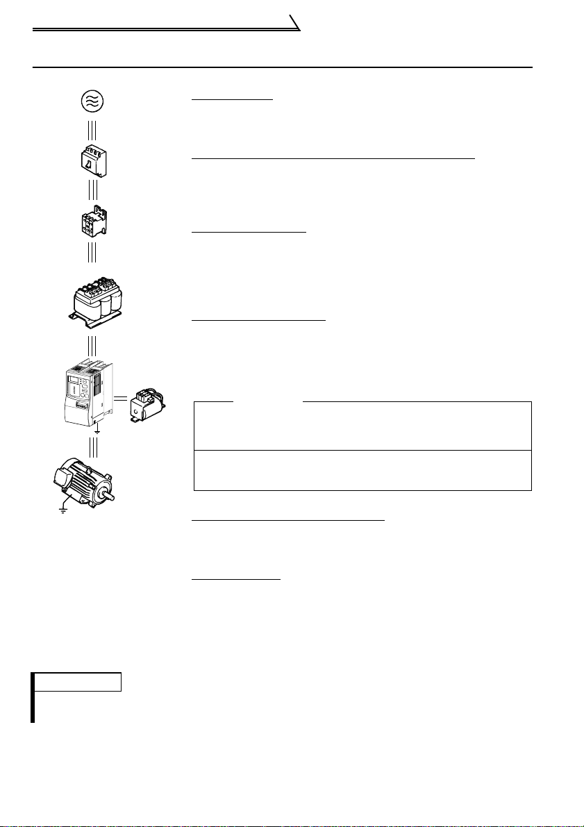
1.1 Basic Configuration
Power supply
Use within the permissible power supply specifications of the
inverter. (Refer to page 178.)
(NFB)
or
(ELB)
(MC)
AC reactor
(FR-BAL)
Earth
(Ground)
Earth (Ground)
DC reactor
(FR-BEL)
No-fuse breaker or earth leakage circuit breaker
The breaker must be selected carefully since an inrush current
flows in the inverter at power-on. (Refer to page 22.)
Magnetic contactor
Do not use this magn etic contacto r to start and stop th e inverter.
Doing so will cause the inverter life to be shorter. (Refer to page
22.)
Installation of reactors
The reactors must be used when the power factor is to be
improved or the inverter is installed near a large power supply
system (500kVA or more and w iring distance within 1 0m). Make
selection carefully. (Refer to page 22.)
Inverter
The inverter life is influenced by ambient temperature. The
ambient temperature should be as low as possible within the
permissible range. (Refer to page 4.)
Wrong wiring might lea d to damage of the inverter. The control
signal wires must be kept fully away from the main circuit to
protect them from noise. (Refer to page 5.)
Devices connected to the output
Do not connect a power factor correction capacitor, surge
suppressor or radio n oi se fi lter to the out put side.
Earth (Ground)
To prevent an electric shock, always earth (ground) the motor and
inverter.
For reduction of induction noise from the power line of the
inverter, it is recommended to wire the earth (ground) cable by
returning it to the earth (ground) terminal of the inverter.
(For details of noise reduction techniques, refer to pa ge 28.)
REMARKS
•When using t he P LC fu nc tion, refer to page 35 for wiring an d to page 98 for details.
•When using t he CC-Link function, refer to page 36 for wiring and to page 140 fo r de ta ils .
2
Page 12
Precautions for Use
1.2 Precautions for Use
Harmonic Suppression Guideline
The "harmonic suppression guideline for household appliances and general-purpose
products" issued by the Ministry of Economy, Trade and Industry (formerly Ministry of
International Trade and Industry) in September, 1994 applies to the FR-C500 series.
By installing the FR-BEL or FR-BAL power factor improving reactor, this product
complies with the "harmonic suppression techniques for transistorized inverters (input
current 20A or less)" established by the Japan Electrical Manufacturers' Association.
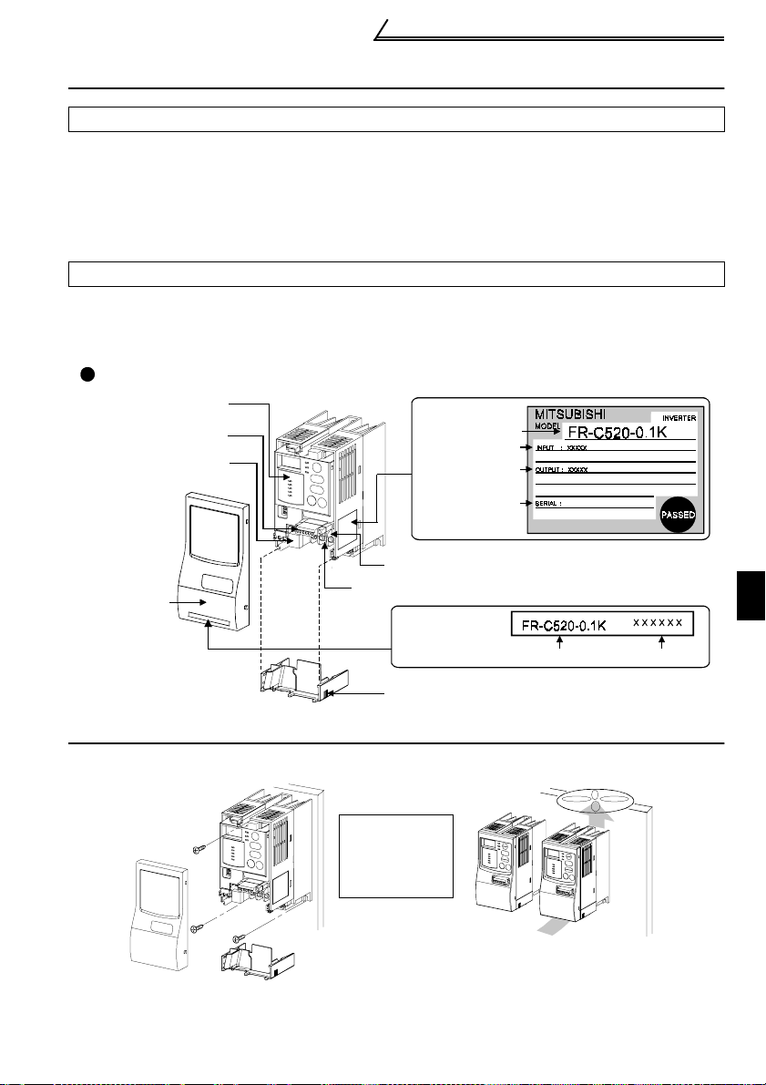
Product Checking and Parts Identification
Unpack the inverter and check the capacity plate on the front cover and the rating
plate on the inverter side face to ensure that the product agrees with your order and
the inverter is intact.
Part names and plates
Operation panel
CC-LINK connector
PU connector
(RS-485 connector)
Rating plate
Inverter type
Input rating
Output rating
Serial number
Control circuit terminal block
Front cover
Main circuit te rm inal block
Capacity plate
Wiring cove r
1.3 Installation of the Inverter
Enclosure surface mounting
Fix the front
cover and wiring
cover after
removing the m .
Leave enough clearances and
provide cooling measures.
3
Inverter type
Mounting inside enclosure
When containing two or more
inverters, ins tall them in parallel
and provide cooling measures.
Serial number
1
INSTALLATION AND WIRING
Page 13
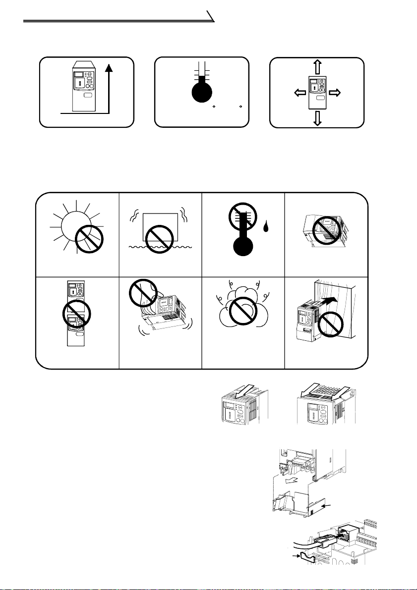
Installation of the Inverter
! Install the inverter under the following conditions:
Vertical mounting
Vertical
Ambient temperature and humidity
Temperature: -10 to 50
Humidity: 90%RH maximum
C C
Clearances
10cm or
more
1cm or
more
1cm or
more
10cm or
more
Clearances also necessary for
changing the cooling f an.
(1.5K or more)
! The inverter consists of precision mechanical and electronic parts. Never install or
handle it in any of the following conditions as doing so could cause an operation
fault or failure.
Direct sunlight
Vibration
(5.9m/s
2
max.)
High temperature,
high humidi ty
Oil mist,
Vertical mountin g (Wh en
mounted inside en closu re)
Transportation by
holding front cover
flammable gas,
corrosive gas,
fluff, dust, etc.
! Removal and reinstallation of the front
cover
Remove the front cover by pulling it
toward you in the direction of arrow.
To reinstall, match the cover to the inverter
front and in st all it straig ht.
FR-C520-0.1K to 0.75K FR-C520-1 .5K to 3.7K
! Removal and reinstallation of the wiring cover
The cover can be removed easily by pulling it toward
you.
To reinstall, fit the cover to th e in verter along the guides.
! Wiring of the RS-485 communication connector
When using the RS-485 connector to wire the cable, you
can cut off the lug of the wiring cover to wire it.
4
Horizontal placement
Mounting to
combustible material
Wiring
cover
Lug
Page 14
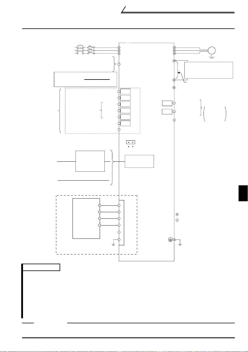
1.4 Terminal Connection Diagram
! Three-phase 200V power input
Three-phase AC
power supply
External transis tor common
24VDC power supply
Contact input common (source)
*2
Input terminals
Personal
computer
Parameter un it
(FR-PU04)
CC-Link co m m u nication signal s
NFB
MC
Be careful not to shor t
PC-SD.
Forward rotation start
Reverse rota tion start
Multi-speed
selection
Sequence start
High
Middle
Low
Contact input common
Control input signals
(No voltage input allowed)
*4
RS-232C
-RS-485
converter
R
S
T
PC
STF
STR
RH
RM
RL
SQ
SD
Inverter
*5
(X0)
(X1)
(X4)
(X3)
(X2)
(X5)
SINK
*1
SOURCE
PU connector
(RS-485)
(Y0)
(Y1)
Terminal Connection Diagram
U
V
W
P1
*5
RUN
ALM
SE
Power factor improving
DC reactor
(FR-BEL: Option)
P
N
Jumper: Remove
this jumper when
FR-BEL is connected.
Running
Alarm
output
Open
Output
terminals *3
collector
output common
Motor
IM
Earth
(Ground)
Open
collector
output
1
DA
DB
DG
SLD
DA
DB
DG
SLD
: Main circuit terminal
: Control circuit terminal
SLD
PLC CC-Link
FG
Earth (Ground)
master module
REMARKS
*1. You can change the control logic between sink and source logic. Refer to page 12 for details.
*2. The terminal functions cha nge with input terminal funct ion selection (Pr. 60 to Pr. 63, Pr.
65, Pr. 505). (Refer to page 68)
(RES, RL, RM, RH, MRS, OH, STR, STF, SQ signal, without function selection)
*3. The terminal functions change with out put terminal function selection (Pr. 64, Pr. 506).
(Refer to page 69.) (RUN, OL, ALM signal, without function selection)
*4. Only either the personal computer (e.g. GX Developer) or parameter unit can be
connected to the PU connector.
*5. For details of the I/O device, refer to page 109.
CAUTION
To prevent a malfunction due to noi se, keep the signal cables more t han 10cm away
from the power cables.
5
INSTALLATION AND WIRING
Page 15
Wiring of the Power Supply and Motor
1.5 Wiring of the Power Supply and Motor
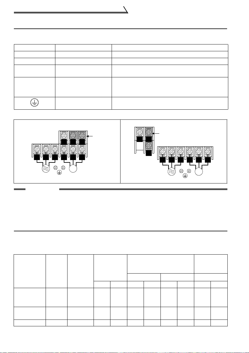
1.5.1 Description of the main circuit terminals
Symbol T erminal Name Description
R/L1, S/L2, T/L3 Power input
U, V, W Inverter output
N/- DC voltage common
Power factor
P/+, P1
improving DC
reactor connection
Earth (Ground)
1.5.2 Layout and wiring of the main circuit terminals
FR-C520-0.1K, 0.2K, 0.4K, 0.75K
!
Connect to the commercial power supply.
Connect a three-ph ase squirrel-cage motor.
DC voltage common terminal. Not isolated from the
power supply and inv erter output.
Disconnect the jumper from t er m inal s P- P1 and
connect the optional po w er fac t or impr oving DC
reactor (FR-BEL).
For earthing (groundi ng) th e inverter chassis. Must
be earthed (grounded) .
FR-C520-1.5K, 2.2K, 3.7K
!
Jumper
P/+
P1
R/L1 S/L2 T/L3
Power supply
U V W
IM
Motor
R/L1 S/L2 T/L3
Power supply
P1
N/- P/+
U V W
IM
Motor
Jumper
N/-
CAUTION
•Always connect the power supply cables to R/L1, S/L2 and T/L3. Never
connect them to U, V and W since it will damage the inverter. (The phase
sequence need not be matched.)
•Connect the motor to U, V and W. When the forward rotation switch (signal) is
turned on at this time, the motor rotates in the counterclockwise direction as
viewed from the load shaft.
1.5.3 Cables, wiring lengths, crimping terminals, etc.
The following selection example assumes the wiring length of 20m.
1) FR-C520-0.1K to 3.7K
PVC
mm
Cables
2
AWG
Applicable
Inverter Type
FR-C520-
0.1K to
0.75K
FR-C520-
1.5K, 2.2K
FRC520-3.7K M4 1.5 5.5-4 5.5-4 3.5 3.5 12 12 4 2.5
Terminal
Screw
Tightening
Torque
Size
M3.5 1.2 2-3.5 2-3.5 2 2 14 14 2.5 2.5
M4 1.5 2-4 2-4 2 2 14 14 2.5 2.5
N•m
Crimping
Terminals
R, S, T U, V , WR, S, T U, V, W R, S, T U, V, WR, S, T U, V, W
Insulated
Cables
2
mm
6
Page 16

Earthing (Grounding) Precautions
! Wiring length
100m maximum
CAUTION
•When the wiring length of the 0.1K or 0.2K is 30m or more, use the carrier
frequency at 1kHz.
•If the inverter-to-motor wiring distance is long, the motor torque will decrease
due to a voltage drop in the main circuit cables especially at low frequency
output. Use thick cables for wiring to make a voltage drop less than 2%.
1.6 Earthing (Grounding) Precautions
! Leakage currents flow in the inverter. To prevent an electric shock, the inverter and
motor must be earthed (grounded). (Class D earthing (grounding), earthing
maximum)
(grounding) resistance 100
! Use the dedicated earth (ground) terminal to earth (ground) the inverter. (Do not use
the screw in the casing, chassis, etc.)
Use a tin plated* crimping terminal to connect the earth (ground) cable. When
tightening the screw, be careful not to damage the threads.
*Plating should not include zinc.
! Use the thickest possible earth (ground) cable. Use the cable whose size is equal to
or greater than that indicated below, and minimize the cable length. The earthing
(grounding) point should be as near as possible to the inverter.
Motor Capacity
2.2kW or less 2(2.5)
3.7kW 3.5(4)
For use as a product compliant with the Low Voltage Directive, use PVC cable
whose size is indicated within parentheses.
! Earth (Ground) the motor on the inverter side using one cable of the 4-core cable.
Ω
2
(Unit: mm
Earth (Ground) Cable Size
200V class
)
1
CAUTION
If the inverter is run in the low acoustic noise mode, more leakage currents flow due to
fast switching operations than in the non-low acoustic noise mode. Always use the
inverter and motor after earthing (grounding) them. When earthing (grounding) the
inverter, always use its earth (ground) terminal.
7
INSTALLATION AND WIRING
Page 17

Control Circuit
1.7 Control Circuit
1.7.1 Description of the control circuit terminals
Symbol
STF
STR
RH
RM
RL
Contact input
SQ
SD
Input signals
(*1)
PC
(*1)
ALM
RUN
Open collector
Output signals
SE
Terminal
Name
Forward
rotation
start
Reverse
rotation
start
Multispeed
selection
Sequence
start
Contact
input
common
(sink)
External
transistor
common
24VDC
power
supply
Contact
input
common
(source)
Alarm
output
Inverter
running
Open
collector
common
Description
Turn on the STF signal
to start forward rotation
and turn it off to stop.
Turn on the STR signal
to start reverse rotation
and turn it off to stop.
You can select mu lti pl e speeds (three
speeds).
Turn on the SQ signal to execute the
built-in PLC function. (RUN state of
the PLC) Turn off the SQ signal to stop
the built-in PLC function. (S TOP stat e
of the PLC)
Common terminal for contact i nputs (terminals STF,
STR, RH, RM, RL, SQ).
Isolated from terminal SE .
When connecting the transistor output (open collector
output) of a programm able controller (PLC), etc.,
connect the positive external power supply for
transistor output to this terminal to prevent a
malfunction due to un desirable current.
It can be used as a 24V 0.1A DC power output across
PC-SD terminals.
Acts as the common terminal of the contact input
signals when sourc e l ogi c is selected.
Low when the inverte r prot ective
function is activated a nd H i gh wh en
the inverter is not in error. (*2)
Low when the inverte r ou tp ut
frequency is the starti ng f re quency or
higher (factory-set to 0. 5H z and
changeable), and H ig h du ring stop or
DC injection brake op eration. (*2)
Common terminal for inverter running terminal RUN.
Isolated from terminal SD.
A stop
command is
given if STF
and STR
signals turn
on at the
same time.
The terminal
functions
change with
input terminal
function
selection (Pr.
60 to Pr. 63,
Pr. 65, Pr.
505). (*3)
The terminal
functions
change with
output
terminal
function
selection (Pr.
64, Pr. 506).
(*4)
Rating
Specifications
Input resistance
4.7kΩ
Open-time
voltage
21 to 27VDC
Short-time
current
4 to 6mADC
Controll ed by
open collector
output or 0V
contact signal
—
Voltage range
18 to 26VDC
Permissible load
current
0.1A
Permissible load
24VDC 0.1A
Permissible load
24VDC 0.1A
—
8
Page 18

Control Circuit
Symbol
—
Terminal
Name
RS-485
connector
Description
• Compliant standard: EIA Sta nda rd RS-485
• Transmission form: Multidrop li nk system
• Communication speed: Maximum 19200bps
• Overall distance: 500m
Rating
Specifications
—
Communication
*1. D o not connect terminals SD and PC each other or to the ground.
For sink logic (fa ct or y setting), terminal SD acts as the commo n terminal of contact in put.
For source logic, terminal PC acts as the comm on terminal of contact input. (Refer to
page 12 for the way to switch between them.)
*2. Low indicates that the open collector ou tput transistor is on (conducts). High indicates
that the transistor is off (does not conduct).
*3. RL, RM, RH, MRS, OH , RES, STF, STR, SQ signal, without function sele ction (Refer to
page 68 for input terminal function selection.)
*4. R UN, OL, ALM signal, without function selection (Refer to page 69 for output ter minal
function selection .)
1
INSTALLATION AND WIRING
9
Page 19
Control Circuit
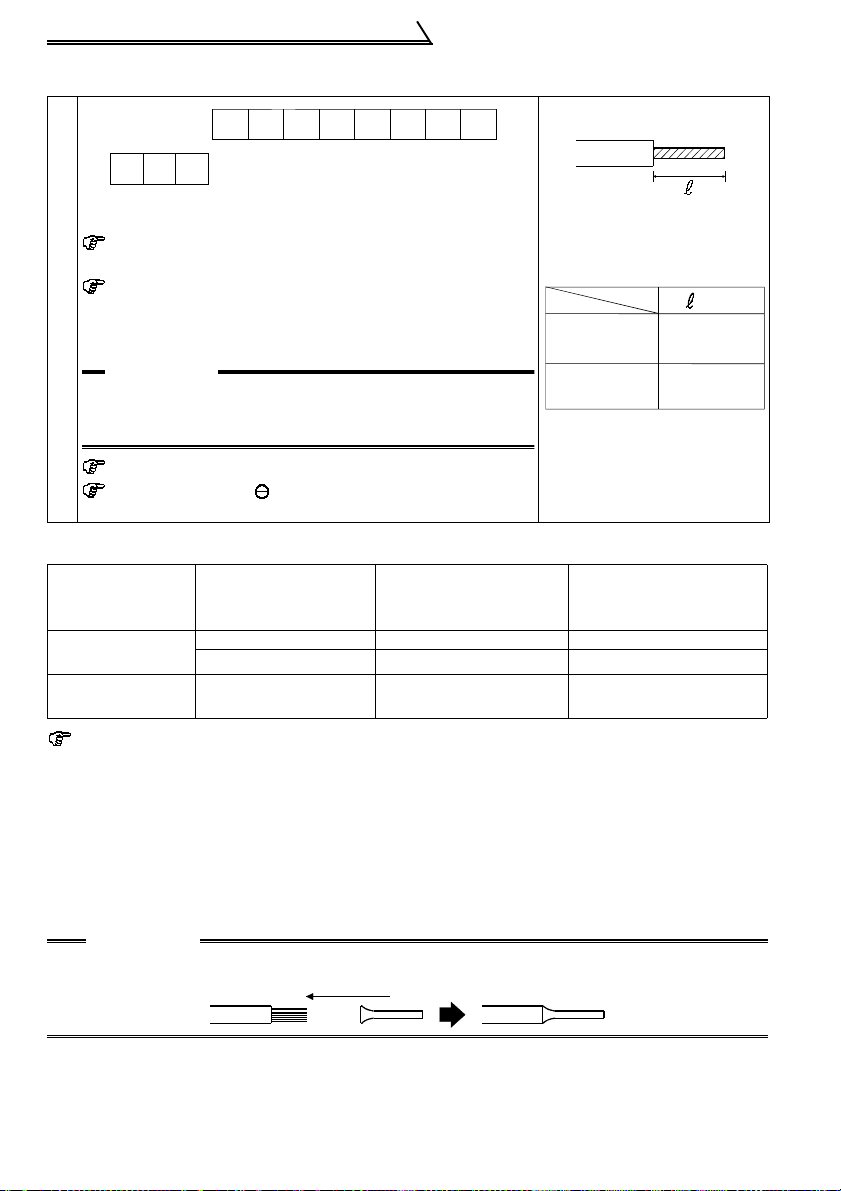
1.7.2 Layout and wiring of the control circuit terminals
STR RL RM RH SQ RUNALMSTF
SD PC
Loosen the terminal scr ew and insert the cable into the
terminal.
Sc re w size : M3 (SD, PC, S E te rmina ls ),
Tightening torque: 0.5N•m to 0.6N•m (SD, PC, SE
SE
M 2 (o the r th a n on th e left)
ter minals )
0.22N•m to 0.25N•m (other than the
above)
CAUTION
Undertightening can cause cable disconnection or
malfunction. Overtightening can ca use a short circuit
Control circuit terminal block
or malfunction due to damage to the screw or unit.
Cable size : 0. 3mm2 to 0.75mm
Screwdriver: Small screwdriver
*Information on bar te rmi nals
Introduced products (as of April, '02): Phoenix Contact Co., Ltd.
T erminal Screw
Size
M3 (SD, PC, SE
terminals)
M2 (other than
above)
Bar terminal crimping tool : CRI M PFO X ZA3 (Phoenix Contac t Co., Lt d.)
(Tip thickness: 0.4mm/tip width: 2.5mm)
Bar Terminal Model
(With insulating
sleeve)
Al 0.5-6WH A 0.5-6 0.3 to 0.5
Al 0.75-6GY A 0.75-6 0.5 to 0.75
Al 0.5-6WH A 0.5-6 0.3 to 0.5
2
Bar Terminal Model
(Without insulating
sleeve)
Cable stripping size
Wire the stripped cable after
twisting it to preven t it from
becoming loose.
In addition, do not solder it. *
(mm)
SD, PC, SE
terminals
Other than
the above
6
5
Wire Size (m m2)
1)Terminals SD and SE are common terminals of the I/O signals. Do not earth
(ground) these common terminals.
2)Use shielded o r twisted cables for conne ction to the control circuit te rminals and run
them away fr om the main and po wer ci rcuits (inclu ding t he 200V rela y seque nce ci rcuit ).
3)The input signals to the control circuit are micro currents. When contacts are
required, use two or more parallel micro signal contacts or a twin contact to prevent
a contact fault.
CAUTION
When using the bar terminal (wi thout insulating sleeve), use care so that the twisted
wires do not come out.
10
Page 20

1.7.3 Layout and wiring of the CC-Link terminals
The terminal block is laid out as shown below.
erminal screw size: M2.5
Control Circuit
Refer to page 36 for details.
DA DB DG
SLD
SLD FG
1
INSTALLATION AND WIRING
11
Page 21
Control Circuit
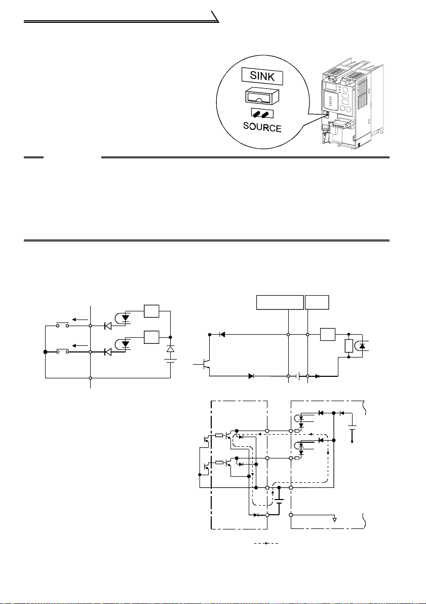
1.7.4 Changing the control logic
The input signals are set to sink logic.
To change the control logic, the jumper
connector must be moved to the other
position.
! Change the jumper connector position
using tweezers, a pair of long-nose pliers,
etc. Change the jumper connector position
before switching power on.
CAUTION
•Make sure that the front cover is installed securely.
•The front cover is fitted with the capacity plate and the inverter unit with the
rating plate. Since these plates have the same serial numbers, always replace
the removed cover onto the original inverter.
•The sink-source logic change-over connector must be fitted in only one of
those positions. If it is fitted in both p ositions at the same time, the inverter
may be damaged.
1) Sink logic type
•In this logic, a signal switches on when a current flows out of the corresponding
signal input terminal.
Terminal SD is common to the contact input signals. Terminal SE is common to the
open collector output signals.
Power
supply
STF
STR
R
Inverter
RUN
R
AX40
1
R
R
SD
•Connecting a positive external power
supply for transistor output to terminal
PC prevents a malfunction caused by
an undesirable current. (Do not
connect terminal SD of the inverter
with terminal 0V of the external power
supply. When using terminals PC-SD
as a 24VDC power supply, do not
install an external power supply in
parallel with the inverter. Doing so may
cause a malfunction in the inverter due
to an undesirable current.)
AY40 transistor
output module
12
1
2
9
9
10
SE
24VDC
STF
STR
24VDC
Current flow
9
Inverter
24VDC
(SD)
PC
SD
Page 22
Control Circuit
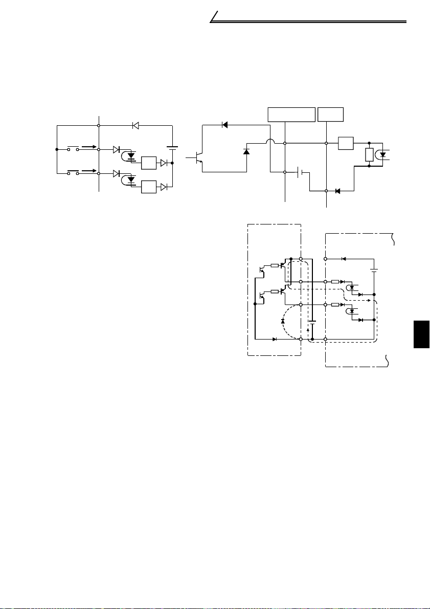
2) Source logic type
•In this logic, a signal switches on when a current flows into the corresponding signal
input terminal.
Terminal PC is common to the contact input signals. For the open collector output
signals, terminal SE is a positive external power supply terminal.
PC
Power
supply
STF
STR
R
R
•Connecting the 0V terminal of the external
power supply for transistor output to terminal
SD prevents a malfunction caused by an
undesirable current.
Inverter
RUN
SE
24VDC
AY80 transistor
output module
10
AX80
1
R
R
9
Inverter
9
1
2
24VDC
PC
STF
STR
SD
24VDC
(SD)
1
13
INSTALLATION AND WIRING
Page 23
Control Circuit
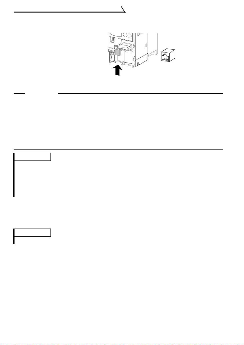
1.7.5 RS-485 Connector
<RS-485 connector pin layout>
View A of the inverter (receptacle
side)
8) to 1)
View A
CAUTION
1. Do not plug the connector to a computer LAN board, fax modem socket,
telephone modular connector, etc. As they are different in electrical
specifications, the inverter may be damaged.
2.Pins 2 and 8 (P5S) ar e provided for th e parameter unit power supply. Do not
use them for any other purpose or when making parallel connectio n by RS485 communication.
3.Refer to page 79 for the communication parameters.
REMARKS
•The PU connector (PS-485) automatically recognizes whether the FR-PU04 or RS-485
communication is connected.
•Refer to page 38 for wiring of the inverter and computer using user program for RS-485
communication.
•Refer to page 35 for wiring of the inverter and personal computer using GX Developer for RS485 communication.
View A
1) SG
2) P5S
3) RDA
4) SDB
5) SDA
6) RDB
7) SG
8) P5S
1.7.6 Connection of the parameter unit (FR- PU04 )
Use the FR-CB2 parameter unit connection cable.
REMARKS
Refer to page 93 for the pa ra m et er s re la te d to parameter unit setting.
""
14
Page 24
Input Terminal s
1.8 Input Terminals
1.8.1 Run (start) and stop (STF, STR)
To start and stop the motor, first switch on the input power supply of the inverter
(switch on the magnetic contactor, if any, in the input circuit during preparation for
operation), then start the motor with the forward or reverse rotation start signal.
POINT
With "1" factory-set in Pr. 507 "inverter operation lock mode setting", the start
signal is not enabled unless the SQ signal is on.
Set "0" in Pr. 507 when performing inverter operation only.
(Refer to page 138 for Pr. 507.)
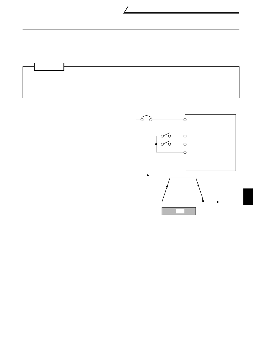
(1) STF, STR
A connection is shown on the right.
1) The forward/reverse rotation signal is
used as both the start and stop signals.
Switch on either of the forward and
reverse rotation signals to start the
motor in the corresponding direction.
Switch on both or switch off the start
signal during operation to decelerate
the inverter to a stop.
2) The frequency setting signal may be
given by setting the required values in
Pr. 4 to Pr. 6 "three-speed setting"
(high, middle, low speeds), by setting
using a sequence l adder, or by setting
from CC-Link. (For three-speed
operation, refer to page 1 7. )
3) After the start s ignal has been i nput, the inverter starts operatin g when the fre quency s etting
signal reaches or exce eds the "starting frequency " set in Pr. 13 (factory-set to 0.5 H z) .
If the motor load torque is large or the "torq ue boos t" set in Pr. 0 is small, the inverter may be
overloaded due to insu fficient t or que.
If the "minimum frequency" set in Pr. 2 (factory setting = 0Hz) is 6Hz, for example, merely
entering the start signal causes the running frequency to reach the minimum frequency of 6Hz
according to the "acceleration time" set in Pr. 7.
4) To stop the motor, operate the DC injection brake for the period of "DC injection brake
operation time" set in Pr. 11 (factory setting = 0.5s) at not more than the DC injectio n brake
operation frequenc y or at not mo re th an 0. 5Hz.
To disable the DC injection brake function, set 0 in either of Pr. 11 "DC injection brake
operation time" and Pr. 12 "DC injection brak e voltage".
In this case, the motor is coated to a stop at not more than the frequency set in Pr. 10 "DC
injection brake op eration frequency " (0 to 120Hz va riable) or at no t more than 0.5Hz (when
the DC injection brake is not operated).
5) If the reverse rot ation signal is i nput during forwar d rotation or the f orward rotation s ignal is
input during reverse rotation, the inverter is decel erated and then switched to the opposite
output polarity without going through the stop mode.
Power
supply
NFB
Forward
rotation star t
Reverse
rotation start
Output frequency
Across STF-SD
(STR)
Connection Example
15
Inverter
R,S,T
STF (Pr.65="17")
STR (Pr.63= " 99 99")
SD
ON
Time
1
INSTALLATION AND WIRING
Page 25
Input Termi na ls
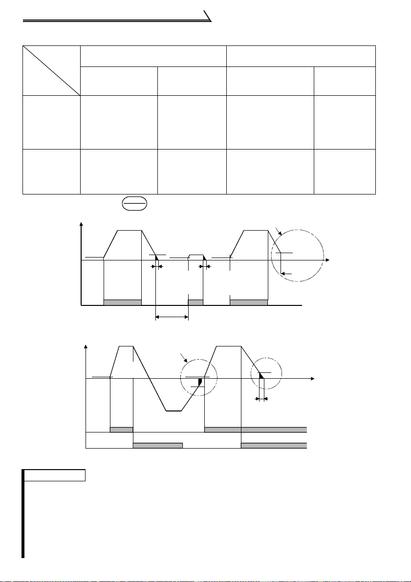
DC Injection Brake and Coasting to Stop
Operation
Mode
DC
Injection
Brake
disconnected (*1)
DC injection brake
DC injection
brake
enabled
operated at not
more than "DC
injection brake
operation frequ ency"
set in Pr. 10
Coasted to a sto p at
DC injection
brake
disabled
not more than "DC
injection brake
operation frequ ency"
set in Pr. 10
*1: Also stopped by the key. Refer to page 71.
Starting frequency
Pr. 13
(*1)
0.5Hz
Output frequency
Start
signal
terminal
Across STF-SD
Across STR-SD
Output frequency
Start
signal
terminal
Across
STF-SD
Across
STR-SD
Forward-Reverse Rotation Switch-Over Timing Chart
External Operation
Pr. 79= "0", "2", "3"
Te rmina ls STF
(STR)-SD
Set frequency
changed to 0Hz
DC injection brake
DC injection
brake operated at
0.5Hz or less.
operated at not more
than "DC injection
brake opera t ion
frequency" set in Pr. 10
Coasted to a stop at
Coasted to a stop
at 0.5Hz or less.
not more than "DC
injection brake
operation frequency"
set in Pr. 10
STOP
RESET
DC injection brake enabl e d DC injection brake d isabled
ON
DC injection brake
operation
frequency Pr. 10
3Hz
0.5Hz
0.5s
DC injection
brake operation
time Pr. 11 (*3)
ON
(*2)
0.5Hz
0.5s
DC injection
brake operation
time Pr. 11 (*3)
Start/Stop Timing Chart
Starting
frequency
Pr.13
(*1)
0.5Hz
Start signal switched on while
DC injection brake is being
operated
Forward
rotation
ON
ON ON
3Hz
Reverse
rotation
0.5Hz
ON
Forward
rotation
PU Operation
Pr. 79= "0", "1", "4"
Set frequency
Stop key
changed to
DC injection
brake operated
at 0.5Hz or less.
Coasted to a
stop at 0.5Hz or
less.
DC injection brake not operated
(*4)
3Hz
Coasted to
a stop
ON
DC injection brake operation
(*4)
frequency Pr. 10
DC injection brake
3Hz
enabled
Time
Time
0.5s
DC injection brake operation
time Pr. 11 (*3)
0Hz
REMARKS
*1. The "st ar ting frequency" in Pr. 13 (factory-set to 0.5Hz) may be set between 0 and 60Hz.
*2. If the nex t start signal is giv en durin g DC injec tio n brake operati on, the D C inject ion brake
is disabled and restart is made.
*3. The "DC injection brake operation time" i n Pr . 1 1 ( factory-set to 0.5s) may be set between 0 and 10s.
*4. The frequency at which the motor is coas ted to a stop is not more t han the "DC injection
brake operation frequency" set in Pr. 10 (factory setting = 3Hz; may be set b et w een 0 and
120Hz) or not more than 0.5Hz.
*5. The "starting frequency" in Pr. 13, "DC injection brake operation time" in Pr. 11 and "DC
injection brake operati on f re quency" in Pr. 10 are the factory-set values.
16
Page 26
Input Terminal s
S
M
s
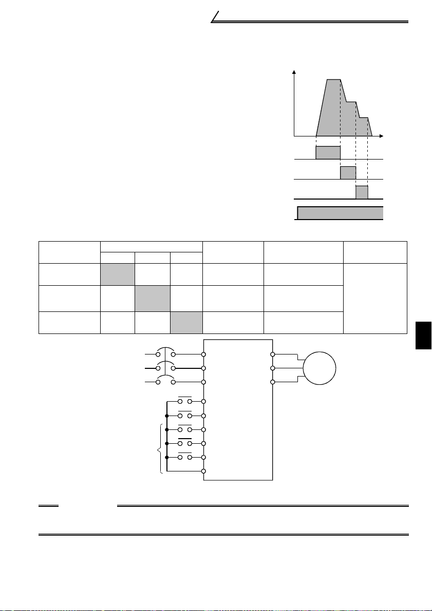
1.8.2 External frequency selection (RH, RM, RL)
Up to three speeds may be selected for an
external command start according to the
combination of connecting the multi-speed select
terminals RH, RM and RL-SD, and multi-speed
operation can be performed as shown on the
right by shorting the start signal terminal STF
(STR)-SD.
Output frequency (Hz)
Speeds (frequencies) may be specified as
desired as listed below using Pr. 4 to Pr. 6.
RH
RM
RL
TF(STR)
Multi-Speed Setting
Speed
Speed 1
(high speed)
Speed 2
(middle
Speed 3
(low speed)
Terminal Input
RH-SD RM-SD RL-SD
Parameter
ON OFF OFF Pr.4
OFF
OFF OFF
Power
supply
ON OFF Pr.5
Forward
rotation
Reverse
rotation
ulti-speed
election
ON Pr.6
R
S
T
STF
STR
RH
RM
RL
SD
Inverter
Set Frequency
0 to 120Hz
0 to 120Hz
0 to 120Hz
U
V
W
Multi-Speed Operation Connection Example
CAUTION
For three-speed setting, selection of two or more speeds sets the frequency of the lower
speed signal.
Range
Motor
Speed 1
(high speed)
Speed 2
(middle speed)
Speed 3
(low speed)
Time
ON
ON
ON
ON
Reference
Page
59
IM
1
INSTALLATION AND WIRING
17
Page 27
Input Termi na ls
1.8.3 Control circuit common terminals (SD, SE)
Terminals SD and SE are both common terminals (0V) for I/O terminals and are
isolated from each other.
Terminal SD is a common terminal for the contact input terminals (STF, STR, RH, RM,
RL, SQ).
Terminal SE is a common terminal for the open collector output terminals (RUN, ALM).
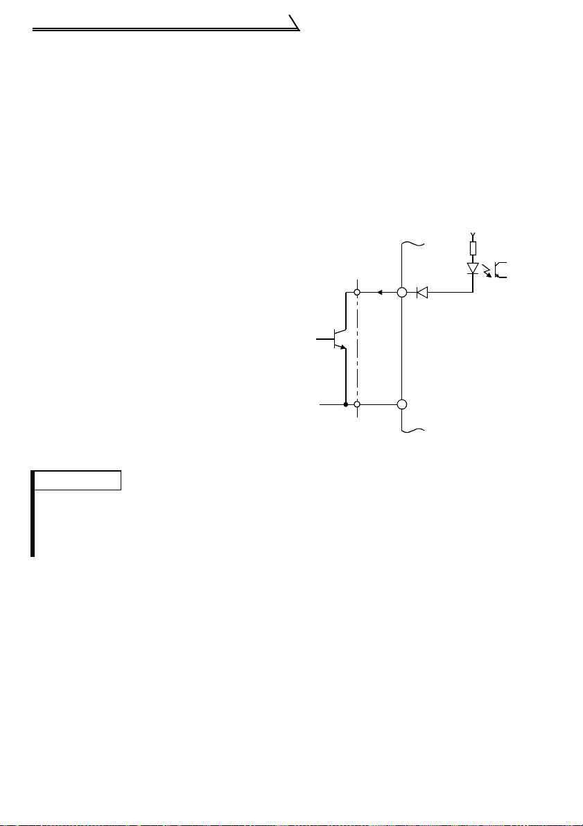
1.8.4 Signal inputs by contactless switches
If a transistor is used instead of a contacted
switch as shown on the right, the input
+24V
signals of the inverter can control terminals
STF, STR, RH, RM, RL, SQ.
STF, etc.
Inverter
SD
External Signal Input
by Transistor
REMARKS
•When using an external transistor connected with the external power supply, use terminal PC
to prevent a malfunction from occurring due to a leakage current. (Refer to page 12.)
•Note that an SSR (solid-state relay) has a relatively large leakage current at OFF time and it
may be accidentally input to the inverter.
18
Page 28
How to Use the Input Signals (Assigned Terminals
A
(
RL, RM, RH, STR, SQ)
1. 9 How to Use the Input Signals (Assigned T erminals RL, RM, RH, STR, SQ)
These terminals can be
changed in function by
setting Pr. 60 to Pr . 63, Pr . 65,
Pr. 505.
Pr. 60 "RL terminal function selection"
Pr. 61 "RM terminal function selection"
Pr. 62 "RH terminal function selection"
Pr. 63 "STR terminal function selection"
Page 68
Pr. 65 "STF terminal function selection"
Pr. 505 "SQ terminal function selection"
1.9.1 Multi-speed setting (RL, RM, RH signals):
Pr. 505 setting
"0, 1, 2"
Pr. 60 to Pr. 63, Pr. 65,
• By entering frequency commands into the RL, RM and RH signals and turning on/off
the corresponding signals, you can perform multi-speed operation (three speeds).
(For details, refer to page 17.)
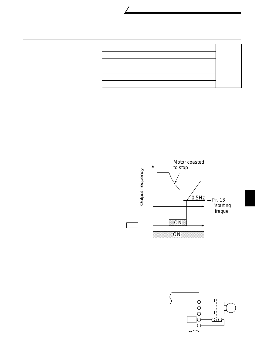
1.9.2 Output shut-off (MRS signal):
Pr. 60 to Pr. 63, Pr. 65, Pr. 505 setting
"6"
Short the output stop terminal MRS-SD during inverter output to cause the inverter to
immediately stop the output. Open terminals MRS-SD to resume operation in about
10ms. Terminal MRS may be used as described below:
(1) To stop the motor by
mechanical brake (e.g.
Motor coasted
to stop
electromagnetic brake)
Terminals MRS-SD must be
shorted when the mechanical
brake is operated and be opened
before motor restart.
(2) To provide interlock to disable
operation by the inverter
After MRS-SD have been shorted,
the inverter cannot be operated if
the start signal is given to the
inverter.
Across
MRS -SD
cross STF
STR)-SD
Output frequency
ON
ON
0.5Hz
Pr. 13
"starting
frequency"
(3) To coast the motor to stop
The motor is decelerated according to the preset deceleration time and is stopped
by operating the DC injection brake at 3Hz or less. By using terminal MRS, the
motor is coasted to a stop.
1.9.3 External thermal relay input:
Pr. 60 to Pr. 63, Pr. 65, Pr. 505 setting
"7"
1
INSTALLATION AND WIRING
When the external thermal relay or thermal relay built in
the motor (e.g. thermal protector) is actuated, the
inverter output is shut off and an alarm signal is given to
keep the motor stopped to protect the motor from
overheat. If the thermal relay contact is reset, the motor
is not restarted unless the reset terminal RES-SD are
shorted for more than 0.1s and then opened or power-on
reset is performed.
Inverter
OH
SD
U
V
W
Thermal relay
Motor
IM
The function may therefore be used as an external
emergency stop signal input.
19
Page 29
How to Use the Input Signals (Assigned Terminals
A
(
RL, RM, RH, STR, SQ)
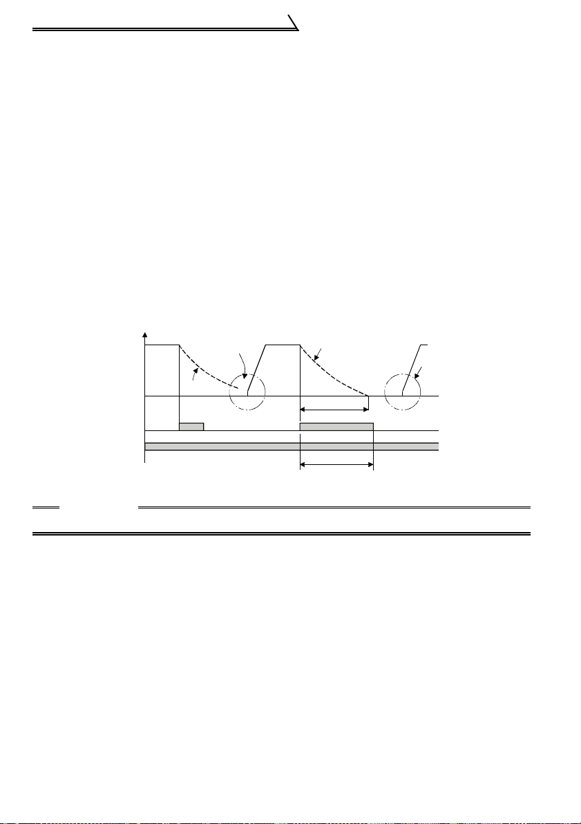
1.9.4 Reset signal:
Pr. 60 to Pr. 63, Pr. 65, Pr. 505 setting
"10"
Used to reset the alarm stop state established when the inverter's protective function
is activated. The reset signal immediately sets the control circuit to the initial (cold)
status, e.g. initializes the electronic overcurrent protection circuit. It shuts off the
inverter output at the same time. During reset, the inverter output is kept shut off. To
give this reset input, short terminals RES-SD for more than 0.1s. When the shorting
time is long, the operation panel or parameter unit displays the initial screen, which is
not a fault.
Operation is enabled after terminals RES-SD are opened (after about 1s).
The reset terminal is used to reset the inverter alarm stop state. If the reset terminal is
shorted, then opened while the inverter is running, the motor may be restarted during
coasting (refer to the timing chart below) and the output may be shut off due to
overcurrent or overvoltage.
Setting either of "1" and "15" in reset selection Pr. 75 allows the accidental input of the
reset signal during operation to be ignored.
(For details, refer to page 71.)
When motor is restarted
Across
RES-SD
cross STF
STR)-SD
during coasting, inverter
activates current limit to
start acceleration.
Coasting
Output frequency (Hz)
ON
ON
Coasting to stop
(Indicates motor speed)
Ordinary
acceleration
Coasting time
ON
T
T: Should be long er than the time
of coasting to stop.
CAUTION
Frequent resetting will make electronic overcurrent protection invalid.
1.9.5 Start (forward rotation) signal:
Pr. 65 set ting
Turn the signal on or off to bring the motor to a forward rotation start or stop.
(Refer to page 15 for details.)
20
"17"
Page 30

How to Use the Input Signals (Assigned Terminals
RL, RM, RH, STR, SQ)
1.9.6 Sequence s t art:
Pr. 60 to Pr. 63, Pr. 65, Pr. 505 setti ng
"50"
Used to execute/stop (RUN/STOP) the built-in PLC function.
Short SQ-SD to execute (RUN) and open SQ-SD to stop (STOP).
Refer to page 100 for details.
1.9.7 No function:
Pr. 60 to Pr. 63, Pr. 65, Pr. 505 setting
"9998"
Disables the input terminal functions.
REMARKS
Refer to page 127 for the no function setting of the external terminal inputs in device D9149
"inverter operation sta tu s co nt ro l en able/disable setting".
1.9.8 Start (reverse rotation) signal:
Pr. 63 setting
"9999"
Turn the signal on or off to bring the motor to a reverse rotation start or stop.
(Refer to page 15 for details.)
1
21
INSTALLATION AND WIRING
Page 31

Peripheral Devices
1.10 Peripheral Devices
1.10.1 Peripheral device list
Selection of peripheral devices (Selection changes depending on
the power input specifications of the inverter.)
! FR-C520-0.1K to 3.7K
No-Fuse
Breaker (NFB
Motor
Output
(kW)
0.1
0.2
0.4
0.75
1.5
2.2
3.7
Inverter
Model
FR-C520-0.1K 30AF/5A
FR-C520-0.2K 30AF/5A
FR-C520-0.4K 30AF/5A FR-BAL-0.4K FR-BEL-0.4K S-N10 2 2
FR-C520-
0.75K
FR-C520-1.5K 30AF/15A FR-BAL-1.5K FR-BEL-1.5K S-N10 2 2
FR-C520-2.2K 30AF/20A FR-BAL-2.2K FR-BEL-2.2K S-N10 2 2
FR-C520-3.7K 30AF/30A FR-BAL-3.7K FR-BEL-3.7K
*1) or Earth
Leakage
Circuit
Breaker (ELB)
(*4)
30AF/10A FR-BAL-0.75K FR-BEL-0.75K S-N10 2 2
Power Factor
Improving AC
Reactor
FR-BAL-0.4K
(*3)
FR-BAL-0.4K
(*3)
Power Factor
Improving DC
Reactor
FR-BEL-0.4K
(*3)
FR-BEL-0.4K
(*3)
Magnetic
Contactor
(MC)
S-N10 2 2
S-N10 2 2
S-N20,
S-N21
*1. Choose the NFB type that meets the power supply capacity.
*2. The sizes of the cables assume t hat the wiring length is 20m.
*3. The power factor may be slight ly le ss.
*4. For ins tal la tions in the United States or Canada, select the UL/cUL-l ist ed breaker.
Cables (mm2)
(*2)
R, S, T
U, V,
3.5 3.5
W
REMARKS
Secondary side measuring in struments
If the wiring length between the inverter and motor is long, the measuring instruments and CT
may generate heat due to line-to-line leakage currents. Therefore, select the devices that have
sufficient current ratings.
1.10.2 Leakage current and installation of earth (ground) leakage circuit breaker
Due to static capacitances existing in the inverter I/O wiring and motor, leakage
currents flow through them. Since their values depend on the static capacitances,
carrier frequency, etc., take the following countermeasures.
(1) To-earth (ground) leakage currents
Leakage currents may flow not only into the inverter's own line but also into the
other line through the earth (ground) cable, etc. These leakage currents may
operate earth (ground) leakage circuit breakers and earth (ground) leakage
relays unnecessarily.
22
Page 32

Peripheral Devices
! Countermeasures
• If the carrier frequency setting is high, decrease the carrier frequency (Pr. 72) of
the inverter.
Note that motor noise increases.
• Using earth leakage circuit breakers designed fo r harmonic and surge s uppression
in the inverter's own line and other line, operation can be performed with the
carrier frequency kept high (with low noise).
(2) Line-to-line leakage currents
Harmonics of leakage
currents flowing in
static capacities
between the inverter
output cables may
operate the external
thermal relay
unnecessarily.
Power
supply
NFB
Inverter
Thermal relay
Line static capacitances
Line-to-Line Leakage Current Path
Motor
IM
! Countermeasures
• Use the electronic overcurrent protection of the inverter.
• Decrease the carrier frequency. Note that motor noise increases.
To ensure that the motor is protected against line-to-line leakage currents, it is
recommended to use a temperature sensor to directly detect motor temperature.
! Installation and selection of no-fuse breaker
On the power receiving side, install a no-fuse breaker (NFB) to protect the primary
wiring of the inverter. Which NFB to choose depends on the power supply side
power factor (which changes with the power supply voltage, output frequency and
load) of the inverter. Especially as the completely electromagnetic type NFB
changes in operational characteristic with harmonic currents, you need to choose
the one of a little larger capacity. (Check the data of the corresponding breaker.) For
the earth leakage circuit breaker, use our product designed for harmonic and surge
suppression. (Refer to page 25 for the recommended models.)
CAUTION
•Choose the NFB type according to the power supply capacity.
•To protect the motor from overheat, t he inverter h as protective fun ction s with
electronic thermal relay. However, when operating two or more motors with a
single inverter or running a multi-pole motor, for example, provide an
overcurrent relay (OCR) between the inverter and m otor. In this case, set the
electronic thermal relay of the inverter for 0A, and set the overcurrent relay for
1.0 time the current value at 50Hz on the motor rating plate, or 1.1 times the
current value at 60Hz, plus the line-to-line leakage current.
1
INSTALLATION AND WIRING
23
Page 33

Peripheral Devices
(3) Selecting the rated sensitivity current for the earth (ground) leakage
breaker
CAUTION
•On the power receiving side, install a no-fuse breaker (NFB) to protect the
primary wiring of the inverter. Selection of NFB depends on the power supply
side power factor (which changes with the power supply voltage, output
frequency and load) of the inverter. Especially as the completely
electromagnetic type NFB changes in operational characteristic with
harmonic currents, you need to choose th e one of a little larger cap acity. For
the earth (ground) leakage circuit breaker, use our product designed for
harmonic and surge suppression.
When using the earth (ground) leakage breaker with the inverter circuit, select its rated
sensitivity current as follows, independently of the PWM carrier frequency.
• Products designed for harmonic and surge suppression
Rated sensitivity current
(lg1+Ign+lg2+lgm)
≥10×
In
• General products
Rated sensitivity current
In
{lg1+Ign+3×(lg2+lgm)}
≥10×
Ig1, Ig2: Leakage currents of cable path during commercial power supply operation
Ign*: Leakage current of noise filter on inverter input side
Igm: Leakage current of motor during commercial power supply operation
Example of leakage current per 1km
in cable path during commercial
power supply operation when the
CV cable is routed in metal conduit
(200V 60Hz)
120
100
80
60
40
20
Leakage current (mA)
0
23.5
8142230386080
5.5
Cable size (mm2)
100
Leakage current example of
3-phase induction motor during
commercial power supply
operation (200V 60Hz)
2.0
1.0
0.7
0.5
0.3
0.2
Leakage current (mA)
150
0.1
1.5 3.7
2.2
Motor capacity (kW)
7.5 152211373055
5.5 18.5
45
<Example>
2
5m 2mm
2mm
Noise filter
NV
Inverter
Ig1 Ign Ig2 Igm
24
2
70m
3
IM
200V1.5kW
Page 34

Peripheral Devices
CAUTION
•The earth (ground) leakage circuit breaker should be installed to the
primary (power supply) side of the inverter.
•In the connection neutral point grounding system, the sensitivity current
becomes worse for earth (ground) faults in the inverter secondary side.
Hence, the protective earthing (grounding) of the load equipment should be
10ΩΩΩΩ or less.
•When the breaker is installed in the secondary side of the inverter, it may
be unnecessarily operated by harmonics if the effective value is less than
the rating.
In this case, do not install the breaker since the eddy current and
hysteresis loss increase and the temperature rises.
•General products indicate the following models: BV-C1, BC-V, NVB, NV-L,
NV-G2N, NV-G3NA, NV-2F, earth (ground) leakage relay (except NV-ZH) , NV
with single-phase, three-wire neutral conductor/open-phase protection
The other models are designed for harmo nic and su rge sup pression:NV-C/
NV-S/MN series, NV30-FA, NV50-FA, BV-C2, earth leakage alarm breaker,
NV-ZH
* Note the leakage current value of the noise filter installed on the inverter input side.
Product designed for
harmonic and surge
General product
suppression
Leakage current Ig1 (mA) 20×
Leakage current Ign (mA) 0 (without noise filter)
Leakage current Ig2 (mA)
Motor leakage current Igm (mA) 0.14
Total leakage current (mA) 1.66 4.78
Rated sensitivity cur r ent (mA)
≥Ig × 10)
(
×
20
30 100
5m
1000m
70m
1000m
=0.10
=1.40
1
25
INSTALLATION AND WIRING
Page 35

Peripheral Devices
1.10.3 Power-off and magnetic contactor (MC)
(1) Inverter's primary side magnetic contactor (MC)
On the inverter's primary side, it is recommended to provide an MC for the following
purposes (refer to page 22 for selection):
1)To release the inverter from the power supply when the inverter's protective function
is activated or when the drive is not functioning (e.g. emergency stop operation).
2)When the external terminal (terminal STF or STR) is used for operation, provide an
MC in the primary side to prevent an accident caused by an automatic restart made
at power restoration after an instantaneous power failure, etc. and to ens ure safety
during maintenance work. When the parameter unit is used for operation, an MC
cannot be used to make a start since an automatic restart is not made after power
restoration. Though the inverter can be stopped with the primary side MC, it is
coasted to a stop.
3)To rest the inverter for a long time.
The control power supply for inverter is always running and consumes a little power.
When stopping the inverter for a long time, switching inverter power of f saves power
slightly.
4) To separate the inverter from the power supply to ensure safety of maintenance/
inspection work.
As the inverter's primary MC is used for the above purposes, select the one of class
JEM1038-AC3 for the inverter input side current when making an emergency stop
during normal operation.
CAUTION
Do not start and stop the inverter frequently using a magnetic contactor. Such
operation can cause the inverter to fail. (The switching life in the inverter input
circuit is about 100,000 times).
(2) Handling of the inverter's secondary side magnetic contactor
In principle, a magnetic contactor provided between the inverter and motor should
not be switched from OFF to ON during operation. Doing so may cause a large
inrush current to flow, leading to a stop due to overcurrent shutoff. If an MC is
provided for such purposes as switch-over to a commercial power supply, the MC
should be switched on/off after the inverter and motor have stopped.
26
Page 36

Peripheral Devices
1.10.4 Regarding the installation of the power factor improving reactor
When the inverter is installed near a large-capacity power transformer (500kVA or
more at the wiring length of 10m or less) or the power capacitor is to be switched, an
excessive peak current will flow in the power supply input circuit, damaging the
converter circuit. In such a case, always install the power factor improving reactor (FRBEL or FR-BAL).
X
Y
Inverter
R
U
S
V
W
T
PP1
FR-BEL (*)
1500
Power factor
improving
reactor
1000
installation range
500
ower supply equipment
apacity (kVA)
0
Wiring length
10
(m)
Power
supply
FR-BAL
NFB
R
S
TZ
REMARKS
* When connecting the FR-BEL, remove the jumper across terminals P<+>-P1.
The wiring length betwee n FR-BEL and inverter should be 5m maximum and as short as
possible.
Use the cables which ar e equal in size to those of the main cir cuit. (Refer to page 6)
CAUTION
•The power factor improving capacitor and surg e suppressor on the inverter
output side may be overheated or damaged by the harmonic com ponents of
the inverter output. Also, since an excessive current flows in the inverter to
activate overcurrent protection, do not insert a capacitor and surge
suppressor. Use a power factor improving reactor for power factor
improvement.
•If a surge voltage occurs in the power supply system, this surge energy may
flow into the inverter, causing the inverter to display OV1, OV2 or OV3 and
come to an alarm stop. In such a case, also install the optional FR-BEL or FRBAL power factor improving reactor.
1
27
INSTALLATION AND WIRING
Page 37

Peripheral Devices
C
p
1.10.5 Regarding noises and the installation of the noise filter
Some noises enter the inverter causing it to malfunction and others are generated by
the inverter causing peripheral devices to malfunction. Though the inverter is designed
to be insusceptible to noises, it handles low-level signals, so it requires the following
general countermeasures to be taken.
(1) General countermeasures
Do not run the power cables (I/O cables) and signal cables of the inverter in parallel
•
with each other and do not bundle them.
Use twisted shield cables for the detector connecting and control signal cables and
•
connect the sheathes of the shield cables to terminal SD.
• Earth (Ground) the inverter, motor, etc. at one point.
• Capacitances exist between the inverter's I/O wiring, other cables, earth (ground)
and motor, through which leakage currents flow to ca use the earth (ground) leakage
circuit breaker, earth (ground) leakage relay and external thermal relay to operate
unnecessarily. To prevent this, take appropriate measures, e.g. set the carrier
frequency in Pr. 72 to a low value, use an earth (ground) leakage circuit breaker
designed for suppression of harmonics and surges, and use the electronic
overcurrent protection built in the inverter.
• The input and output of the inverter main circuit include high-degree harmonics,
which may disturb communication devices (AM radios) and sensors used near the
inverter. In this case, disturbance can be reduced by mounting the FR-BIF radio
noise filter (for input side only) or FR-BSF01 line noise filter.
Noise reduction technique examples
Install filter (FR-BSF01)
on inverter's input side.
nverter
ower supply
Install filter FR-BLF on
inverter's input side.
Separate inverter and power
line more than 30cm (at least
10cm) from sensor circuit.
ontrol
ower supply
Do not earth (ground)
control box directly.
Do not earth (ground) control cable.
Control box
FR-
BSF01
FRBIF
Reduce carrier frequency.
Inverter
Power
supply
for sensor
FR-
BSF01
Use twisted pair shielded cable.
Do not earth (ground) shield but connect
it to signal common cable.
28
Install filter (F R - BS F 0 1)
on inverter's output side.
Motor
IM
Use 4-core cable for motor
power cable and use one
cable as earth (ground) cab le.
Sensor
Page 38

Peripheral Devices
1.10.6 Power harmonics
The inverter may generate power harmonics from its converter circuit to affect the
power generator, power capacitor, etc. Power harmonics are different from noise and
leakage currents in source, frequency band and transmission path. Take the following
suppression techniques.
!
!The following table indicates differences between harmonics and noise:
!!
Item Harmonics Noise
Normally 40th to 50th
Frequency
Environment
Quantitative
understanding
Generated
amount
Affected
equipment
immunity
Suppression
example
!
!Suppression technique
!!
degrees or less (up to 3kHz or
less)
To-electric channel, power
impedance
Theoretical calculation
possible
Nearly proportional to load
capacity
Specified in standard per
equipment
Provide reactor Increase distance
Harmonic currents produced on the
power supply side by the inverter
change with such conditions as
whether there are wiring impedances
and a power factor improving reactor
and the magnitudes of output
frequency and output current on the
load side.
For the output frequency and output
current, we understand that they
should be calculated in the conditions
under the rated load at the maximum
operating frequency.
CAUTION
The power factor improving capacitor and surge suppressor on the inverter
output side may be overheated or dama ged by t he ha r monic com ponents of the
inverter output. Also, sinc e an exces sive cu rrent flow s in the inv erter to acti vate
overcurrent protection, do not provid e a capa ci tor and sur ge suppr ess or o n the
inverter output side when the motor is driven by the inverter. To improve the
power factor, insert a power factor improving reactor in the inverter's primary
side or DC circuit. For more detailed information, refer to page 27.
High frequency (sever al 10kHz to 1GHz
order)
To-space, distance, w iring path
Random occurrence, quantitative grasping
difficult
Change with current variation ratio (larger as
switching speed incr eases)
Different depending on manufacturer's
equipment specifications
Power facto r
NFB
Power facto r
improving
AC reactor
improving
DC reactor
Inverter
Do not provide power
factor improving capacitor.
Motor
IM
1
INSTALLATION AND WIRING
29
Page 39

Peripheral Devices
1.10.7 Power harmonic suppression guideline
Harmonic currents flow from the inverter to a power receiving point via a power
transformer. The harmonic suppression guideline was established to protect other
consumers from these outgoing harmonics.
1)[Harmonic suppression guideline for household appliances and general-purpose
products]
The "harmonic suppression guideline for household appliances and generalpurpose products" issued by Ministry of Economy, Trade and Industry (formerly
Ministry of International Trade and Industries) in September, 1994 applies to the
FR-C500 series. By installing the FR-BEL or FR-BAL power factor improving
reactor, this product complies with the "harmonic suppression techniques for
transistorized inverters (input current 20A or less)" established by the Japan
Electrical Manufacturers' Association.
2)[Harmonic suppression guideline for specific consumers]
This guideline sets forth the maximum values of harmonic currents outgoing from a
high-voltage or specially high-voltage consumer who will install, add or renew
harmonic generating equipment. If any of the maximum values is exceeded, this
guideline requires that consumer to take certain suppression measures.
T abl e 1 Maxi mum V a lues of Outgo ing Harmoni c Curr ents per 1k W Cont ract Po wer
Received
Power
5th 7th 11th 13th 17th 19th 23rd
Voltage
6.6kV 3.5 2.5 1.6 1.3 1.0 0.9 0.76 0.70
22kV 1.8 1.3 0.82 0.69 0.53 0.47 0.39 0.36
33kV 1.2 0.86 0.55 0.46 0.35 0.32 0.26 0.24
Application of the harmonic suppression guideline for specific consumers
(1)
Over
23rd
New installation/addition/
renewal of equipment
Calculation of equivalent
capacity sum
Not more
than reference
capacity
Over reference capacity
equivalent capa cit i es
Calculation of outgoing
harmonic current
harmonic current equal to
or lower than maximum
Harmonic suppression
technique is not required.
Sum of
Is outgoing
value?
Not more than
maximum value
Over maximum value
Harmonic suppression
technique is required.
30
Page 40

Peripheral Devices
Table 2 Conversion Factors for FR-C
Class Circuit Type Conversion Factor Ki
Withou t reactor K31=3.4
3-phase bridge
3
(Capacitor-smoothed)
With reac tor (AC sid e ) K32=1.8
With reac tor (DC sid e ) K33=1.8
With rea c t o rs (AC, DC sides) K34= 1.4
500
Series
Table 3 Equivalent Capacity Limits
Received Power Voltage Reference Capacity
6.6kV 50kVA
22/33kV 300kVA
66kV or more 2000kVA
Table 4 Harmonic Content (Values at the fundamental current of 100%)
Reactor 5th 7th 11th 13th 17th 19th 23rd 25th
Not used 65 41 8.5 7.7 4.3 3.1 2.6 1.8
Used (AC side) 38 14.5 7.4 3.4 3.2 1.9 1.7 1.3
Used (DC side) 30 13 8.4 5.0 4.7 3.2 3.0 2.2
Used (AC, DC
sides)
28 9.1 7.2 4.1 3.2 2.4 1.6 1.4
1)Calculation of equivalent capacity P0 of harmonic generating equipment
The "equivalent capacity" is the capacity of a 6-pulse converter converted from the
capacity of consumer's harmonic generating equipment and is calculated with the
following equation. If the sum of equivalent capacities is higher than the limit in
Table 3, harmonics must be calculated with the following procedure:
P0=
(Ki×Pi) [kVA]
Σ
Ki: Conversion factor (refer to Table 2)
Pi: Rated capacity of harmonic generating
equipment* [kVA]
i: Number indicating the conversion
circuit type
*Rated capacity: Determined by the
capacity of the applied motor and
found in Table 5. It should be
noted that the rated capacity used
here is used to calculate
generated harmonic amount and
is different from the power supply
capacity required for actual
inverter drive.
1
INSTALLATION AND WIRING
2)Calculation of outgoing harmonic current
Outgoing harmonic current=fundamental wave current (value converted from
received power voltage)×operation ratio×harmonic content
• Operation ratio:Operation ratio=actual load factor×operation time ratio during 30
minutes
• Harmonic contents: Found in Table 4.
31
Page 41

Peripheral Devices
Table 5 Rated Capacities and Outgoing Harmonic Currents for Inverter Drive
Rated
Applie
Motor
Current
d
(kW)
0.4 0.81 49 0. 57 31.85 20.09 4.165 3.773 2.107 1.519 1.274 0 .882
0.75 1.37 83 0.97 53.95 34.03 7.055 6.391 3.569 2.573 2.158 1.494
1.5 2.75 167 1.95 108.6 68.47 14.20 12.86 7.181 5.177 4.342 3.006
2.2 3.96 240 2.81 156.0 98.40 20.40 18.48 10.32 7.440 6.240 4.320
3.7 6.50 394 4.61 257.1 161.5 33.49 30.34 16.94 12.21 10.24 7.092
[A]
400V 5th 7th 11th 13th 17th 19th 23rd 25th
6.6kV
Fundamental
Wave
Current
Converted
(mA)
Rated
Capacity
(kVA)
Outgoing Harmonic Current Converted from
6.6kV (mA) (No reactor, 100% operation ratio)
3)Harmonic suppression technique requirement
If the outgoing harmonic current is higher than; maximum value per 1kW contract
power×contract power, a harmonic suppression technique is required.
4)Harmonic suppression techniques
No. Item Description
Reactor installation
1
(ACL, DCL)
Installation of power
2
factor improving
capacitor
Transformer multi-phase
3
operation
4 AC filter
Passive filter
5
(Active filter)
Install a reactor (ACL) in the AC side of the inverter or a reactor
(DCL) in its DC side or both to su ppress outgoing harmonic
currents.
When used with a series re actor, the power factor improving
capacitor has an effect of absor bi ng harmonic currents.
Use two transformers with a phase angle difference of 30° as in
- , - comb i nation to provide an effect cor responding to
12 pulses, reducing low-degree harmonic currents.
A capacitor and a reactor are used together to reduce
impedances at specific frequencies, producing a great effect of
absorbing harmonic currents.
This filter detects the current of a circ ui t generating a harmonic
current and generates a harmonic current equivalent to a
difference between that current and a fundamental wave
current to suppress a harm onic current at a detection poi nt ,
providing a great effect of abso rb i ng harmonic currents.
32
Page 42

Connection of Stand-Alone Option Units
1.1 1 Connection of Stand-Alone Option Units
1.1 1.1 Connection of the conventional BU brake unit (option)
Connect the BU brake unit correctly as shown below . Incorrect connection will damage
the inverter.
NFB
Remove
jumpers.
MC
PC
ON
OFF
MC
HBHA TB
HC
OCR
MC
R
S
T
P
BU brake unit
Inverter
U
V
W
N
Discharge resistor
P
PR
Motor
IM
N
OCR
CAUTION
1. The wiring distance between the inverter, brake unit and discharge resistor
should be within 2m. If twisted wires a re used, the di stance sh ould b e within 5m.
2. If the tran sistors in the brake unit should fail, the resistor can be extremely
hot, causing a fire. Therefore, install a magnetic contactor on the inverter's
power supply side to shut off a current in case of failure.
1.11.2 C onnection of the FR-HC high power factor converter (option)
When connecting the high power factor converter (FR-HC) to suppress power
harmonics, wire securely as shown below. Incorrect connection will damage the high
power factor converter and inverter.
1
Power
supply
RST R4S4T4
NFB
MC1MC2
High power factor converter (FR-HC)
R4 S4 T4
From FR-HCL02
S3 T3
R3
MC2
External box
MC1
R2
S2
T2
FR-HCL01
R
S
T
NP
33
Y1orY2 RDY RSO SE
Inverter
R
S (Note 1)
T
SD
RES (Note 3)
MRS (Note 3)
N
P
INSTALLATION AND WIRING
Page 43

Connection of Stand-Alone Option Units
3
A
s
CAUTION
1. Always keep the power input terminals R, S and T open. Incorrect connection
will damage the inverter. Opposite polarity of terminals N/-, P/+ will damage the
inverter.
2. The voltag e phases of terminals R, S, T and terminals R4, S4, T4 must be
matched before connection.
3. Use Pr. 60 to Pr. 63, Pr. 65 and Pr. 505 (input terminal function selection) to
assign the terminals used for the MRS and RES signals.
4. When the FR-HC is connected , use sink logic (factory setting). For source
logic, the FR-HC cannot be connected.
1.11.3 Connection of the power regeneration common converter (FR-CV)
When connecting the FR-CV power regeneration common converter, connect the
inverter terminals (P/+, N/-) and FR-CV power regeneration common converter
terminals as shown below so that their symbols match with each other.
R
(Note 1)
S
T
-phase
C power
upply
NFB
MC1
Dedicated
stand-alone
reactor (FR-CVL)
R/L11
R2/L12
S2/L22
S/L21
T2/L32
T/L31
FR-CV power
regeneration
common converter
R2/L1
S2/L2
T2/L3
R/L11
S/L21
T/MC1
P/L+
N/LP24
SD
RDYA
RDYB
RSO
SE
Inverter
P
N
PC
SD
MRS(Note 3)
RES(Note 3)
CAUTION
1. Always keep R/L1, S/L2 and T/L3 of the inverter open. Incorrect connection
will damage the inverter. Opposite polarity of terminals N/-, P/+ will damag e
the inverter.
2. The volt age phases of terminals R/L11, S/L21, T/MC1 and terminals R2/L1,
S2/L2, T2/L3 must be matched before connection.
3. Use Pr. 60 to Pr. 63, Pr. 65 and Pr. 505 (input terminal function selection) to
assign the terminals used for the RES and MRS signals.
U
IM
V
W
34
Page 44

Wiring of the Inverter and Personal Computer Using
GX Developer for RS-485 Communication
1.12 Wiring of the Inverter and Personal Comp uter Using G X De v e lo p e r fo r R S - 4 85 Commun ic a tio n
Personal computer
GX Developer :
Programming tool
RS-232C
connector
Inverter
RS-485
connector
!Personal computer - inverter connection cable
Make connection after conversion between RS-232C and RS-485.
Examples of commercially available products (as of April, '02)
Type Maker
FA -T-RS40 (with connectors and cable)
*The telephone numbers are subject to change without notice.
"
Mitsubishi Electric Engineering Co. , Ltd .
REMARKS
When fabricating the cabl e on the user side, refer to page 39.
!
!Refer to page 98
!!
for details of the PLC function.
1
35
INSTALLATION AND WIRING
Page 45

Wiring for CC-Link Communication
1.13 Wiring for CC-Link Communi cati on
(1) Wiring method
Wiring of the inverter and CC-Link master module is shown below.
C-Link master module
Power
supply
DA
DB
DG
SLD
R
S
T
DA
DB
DG
SLD
FG
Inverter
U
V
W
Motor
(2) Connection of multiple inverters
Multiple inverters can be Factory-Automated by sharing a link system as one
remote device station of CC-Link and monitoring control with a PLC user
program.
Master module
erminat ing
esistor*
DA
DB
DG
SLD
FG
Shielded twiste d
cable
Inverter Inverter
DA
DB
DG
SLD
FG
Shielded twiste d
cable
DA
DB
DG
SLD
FG
Terminating
resistor*
*Use the terminating resistors supplied with the PLC.
1)Maximum number of inverters connected to one master station
42 inverters (when only inverters are connected)
When there are other modules, the following conditions must be satisfied
since the number of occupied stations changes depending on the modules.
{(1 a)+(2 b)+(3 c)+(4 d)} 64
a: Number of one-station occupying modules
b: Number of two-station occupying modules
{(16 A)+(54 B)+(88 C)} 2304
A: Number of remote I/O stations 64 stations
B: Number of remote device stations 42 stations
C: Number of local, standby master and intelligent device stations 26 stations
c: Number of three-station occupying modules
d: Number of four-station occupying modules
36
Page 46

Wiring for CC-Link Communication
C
(3) Wiring method
1) Use CC-Link dedicated cables and strip off their sheaths. A too long strip-off
length may cause a short circuit with the adjacent cable. A tool short strip-off
length may cause the cable to come off. Use the recommended cable. For
details, refer to the CC-Link catalog or visit the MELFANSweb home page of
Mitsubishi Electric FA Equipment Technology Information Service at http://
www.nagoya.melco.co.jp/. (Introduced in Product details (FA network) - CC-Link.)
Recommended tightening torque: 0.22N•m to 0.25N•m
Use a small screwdriver (tip thickness: 0.6mm/overall length: 3.5mm).
(4) Recommendation of bar terminal
6.5mm 0.5mm
For wiring of the CC-Link communication signals, two CC-Link dedicated cables
must be wired to one terminal block.
The following terminal and tool are recommended for use of bar terminals.
1)Recommended bar terminal, crimping tool
•Contact: Phoenix Contact Co., Ltd.…045-931-5602
•Bar terminal type: AI-TWIN2×0.5-8WH
•Crimping tool type: CRIMPFOX UD6, ZA3
2)Connection of terminating resistor
Connect a terminating resistor between terminals DA-DB of the inverter at a
termination.
Use the terminating resistor supplied with the PLC master module after working
on it.
Tube
ut here. Cut tube.
Note: If the resistor is not supplied with the
master module, use a 110Ω, 1/2W resistor
commercially available.
3)Connection of the shielded wires of the CC-Link dedicated cable
Connect the shielded wires of the CC-Link dedicated cable to terminal SLD after
twisting them.
Shielded wires
1
INSTALLATION AND WIRING
Shielded wires
Note: The two SLD terminals are connected inside the inverter.
!
!Refer to page 140 for details of CC-Link communication.
!!
37
Page 47

Wiring of the Inverter and Computer Using RS-485
comm unication
1.14 Wiring of the Inverter and Computer Using RS-485 communication
Refer to page 79 for the setting related to RS-485 communication operation.
<System configuration example>
(1) Connection of a computer to the inverter (one-to-one connection)
Station No.0
Inverter
RS-485
connector
RJ-45 connector 2)
10BASE-T cable 1)
RS-485
Interfase
terminal
Computer
Station No.0
Inverter
RS-485
connector
RJ-45
connector 2)
10BASE-T cable 1)
RS-232C
cable
RS-232C RS-485
Computer
RS-232C
connector
converter
Maximum
15m
!Computer - inverter connection cable
For a connection cable between the computer having RS-232C and the inverter
(RS-232C ⇔ RS-485 converter), refer to the table below.
Examples of commercially available products (as of July, '02)
Type Maker
FA-T-RS40 *
"
Mitsubishi Electric Engin eer ing
Co., Ltd
* You can not connect multiple inverters with a converter cable (a computer and an
inverter are one-to-one connection). As the RS-232C cable and the RS-485 cable
(10BASE-T+RJ-45 connector) are provided with a product, no need to prepare a
cable and a connector separately. Contact a maker for details of the product.
REMARKS
When fabricating th e cable on the user side, see belo w.
Examples of commercially av ai l able products (as of July, '02)
Product Type Maker
SGLPEV-T 0.5mm × 4P
1) 10BASE-T cable
2) RJ-45 connector 5-554720-3 Tyco Electronics Corporation
* Do not use No.2 and No.8 pin
(P5S).
38
Mitsubishi Cable Industries, Ltd.
Page 48

Wiring of the Inverter and Com puter Using RS -485
comm unication
(2) Connection of a computer to multiple inverters (one-to-n connection)
RS-485
Computer
Station No. 1
Inverter
RS-485
connector
Station No. 2
Inverter
RS-485
connector
Station No. n (u p to 32 )
Inverter
RS-485
connector
interface
terminal
Distributor
RS-232C
cable
Computer
RS-232C
connector
Maximum
Converter
10BASE-T cable 1)
Station No. 1
Inverter
RS-485
connector
15m
Distributor
10BASE-T cable
1)
RJ-45 connector
Station No. 2
Inverter
RS-485
connector
RJ-45 connector
2)
Station No. n
Inverter
RS-485
connector
2)
REMARKS
When fabricating the cable on the user side, see belo w.
Examples of commercially available products (as of July, '02)
Product Type Maker
1) 10BASE-T cable SGLPEV-T 0.5mm × 4P * Mitsubishi Cable Industries, Ltd.
2) RJ-45 connector 5-554720-3 Tyco Electronics Corporation
* Do not use No. 2 and No. 8 pin (P5S) of the 10 BASE-T cable.
Terminating
resistor
Terminating
resistor
1
39
INSTALLATION AND WIRING
Page 49

Design Information
1.15 Design Information
1) Provide electrical and mechanical interlocks for MC1 and MC2 which are used for
commercial power supply-inverter switch-over.
When there is a commercial power supply-inverter switch-over circuit as shown
below, the i nverter will be damaged by leakage current from the power supply due to
arcs generated at the time of switch-over or chattering caused by a sequence error.
2)If the machine must not be restarted when power is restored after a power failure,
provide a magnetic contactor in the inverter's primary circuit and also make up a
sequence which will not switch on the start signal.
If the start signal (start switch) remains on after a power failure, the inverter will
automatically restart as soon as the power is restored.
3)Since the input signals to the control circuit are on a low level, use two parallel micro
signal contacts or a twin contact for contact inputs to prevent a contact fault.
4)Do not apply a voltage to the contact input terminals (e.g. STF) of the control circuit.
5)Make sure that the specifications and rating match the system requirements.
1)Commercial power supply-inverter
switch-over
MC1
Interlock
R
Power
supply
U
V
S
W
T
Leakage current
MC2
IM
Inverter
6)For use in the following application where speed control is performed using a sensor
input-based conveyor program with the signals of sensors , and entered
into the STF, STR and RL terminals, respectively, and the built-in PLC function set
for terminal function disable (D9148), the built-in PLC function is not set for terminal
function disable but for STF, STR and RL terminal function enable in the factory
setting status (Pr. 507=0) when the built-in PLC function is in a STOP status or there
is no program, and the inverter operates if any of the sensors is blocked. (Refer to
page 138 for Pr. 507 "inverter operation lock mode setting".)
3)Low-level signal contacts
Low-level
ignal contacts
A
B C
Twin contact
A
Work
Conveyor
<Connection diagram>
B
C
IM
Inverter
Motor
A
Start sensor
Deceleration
B
sensor
C
Stop sensor
40
Inverter
U
R
S
T
STF
STR
RL
SD
W
A
B
C
IM
V
Page 50

2. OPERATION AND CONTROL
This chapter describes "operation and control" for use of this
product.
Always read the instructions before use.
2.1 Parts Identification and Functions of the
Operation P a ne l....... .. ............... ............................
2.2 Operation Mode Switching.................................. 42
2.3 Monitor Transition................................................ 43
2.4 Monitoring the Output Current............................ 43
2.5 Displaying the CC-Link Data (Station Number,
Baudrate)...............................................................
2.6 LED On/Off Operations ........................................ 44
42
43
Chapter 1
Chapter 2
41
Chapter 3
Chapter 4
Chapter 5
Chapter 6
Chapter 7
Page 51

Parts Identification and Functions of the Operation
Panel
2.1 Parts Identification and Functions of the Operation Panel
The operation panel cannot be removed from the inverter.
Used to switch between PU and
external operation modes. When
using external operation mode,
press this key to light up EXT
indication.
PU: PU operation mode
EXT: External operat ion mode
Run command forward rotation.
Set reverse rotation using Pr. 17.
Used to stop operation or reset
alarm.
Used to switch monitor or
display data.
Monitoring 3-digit LED
Displays frequency,
parameter number, et c.
CC-Link
RUN
PU
PU
EXT
EXT
RUN
STOP
P.RUN
RESET
L.RUN
SD
RD
L.ERR
MODE SET
Used to switch setting mode.
2.2 Operation Mode Switching
Using , switch between the "PU operation mode" and "external operation mode".
PU
EXT
External
operation mode
PU
EXT
PU
operation mode
The PU indication is lit in the PU operation mode.
The EXT indication is lit in the external operation mode.
REMARKS
Operation mode swit ching that can be perfo rmed usin g is disabled if the Pr. 79 setting is
other than 0 (factory sett ing) . (Ref er to page 75.)
42
PU
EXT
Page 52

2.3 Monitor Transition
Power on
Hold down key.
SET
Monitor Transition
Return
Frequency monitor
MODE
CC-Link
station number
MODE
Release key.
Press MODE key.
Hold down key.
Release key.
Press MODE key.
SET
SET
SET
Current monitor
CC-Link
baudrate
display
0:156kbps
1:625kbps
2:2.5Mbps
3:5Mbps
4:10Mbps
2.4 Monitoring the Output Current
POINT
Hold down the key in the monitor mode to switch from the output curren t
SET
to the frequency.
Operation
1.
Press the key to switch to
the output frequency monitor.
Whether the inverter is running, at a
2.
stop or in any operation mode,
holding down the key displays
the output current.
3.
Release the key to return to
the output frequency monitor mode.
MODE
SET
SET
SET
Hold down.
Display
(1.0A)
2.5 Displaying the CC-Link Data (Station Number, Baudrate)
2
POINT
Hold down the key in the CC-Link display mod e to switch from the station
SET
number to the baudrate.
Operation
Press the key to switch to the
1.
CC-Link station number display mode.
Whether the inver ter is running, at a
2.
stop or in any operation mode,
holding down the key displays
the baudrate.
Release the key to return to
3.
the CC-Link station number display.
MODE
SET
SET
SET
Hold down.
43
Display
OPERATION AND CONTROL
Page 53

LED On/Off Operations
2.6 LED On/Off Operations
LED Description
On: During forward rotat io n operation
RUN
PU
EXT
P.RUN
L.RUN On during CC-Link communication.
SD On during CC-Link data send.
RD On during CC-Link data receive.
L.ERR Turned on when a CC-Link communication error occurs.
CC-Link communicat i on
Slow flicker (1.4s intervals ): During reverse rotation operation
Fast flicker (0.2s intervals): Indicates that the inve rter is not operating but is
given the or start command.
On: PU operation mode
• In the CC-Link operation mode , the PU and EXT LEDs flicker slowly.
On: External operation mode
• In the CC-Link operation mode , the PU and EXT LEDs flicker slowly.
• On during PLC function operation. (Turned on when the SQ-SD
terminals are shorted. (Refer to page 100.))
• Flickers when a PLC self-diagnostic error occurs.
RUN
REMARKS
*When the FR-PU04 is connected, the LEDs (PU, EXT) are not lit.
44
Page 54

LED On/Off Operations
2.6.1 How to check the LED lamps for CC-Link
communication errors
(1) When one inverter is connected
The following table indicates the fault causes that can be determined from the inverter
LED states under the condition that the SW, M/S and PRM LEDs of the master module
are off (the master module has been set properly) in the system configuration where
one inverter is connected.
CPU
Master
module
Power supply
Station No. 1
Inverter
LED States
L.RUN SD RD L.ERR
!
!#
!#
!##
!#
!# #
!##
!###
#
##
##
###
##
## #
###
####
##
#
!
####
Normal communication is made but CRC error occurred due to
noise.
Normal communication
Hardware fault
Hardware fault
Receive data is in CRC error and response cannot be made.
Data addressed to the host does not arrive.
Hardware fault
Hardware fault
Polling response is made but refresh receive is in CRC error.
Hardware fault
Hardware fault
Hardware fault
Data addressed to th e ho st is in CRC error.
Data addressed to th e ho st does not exist or cannot be recei ved
due to noise.
Hardware fault
Data cannot be received due to cable breakage, etc.
Baudrate or station number setting illega l.
!
Baudrate or station number changed midway.
WDT error (hardware fault) , pow er off, power supply section fault
Cause
: On, # : Off, : Flicker
!
2
OPERATION AND CONTROL
45
Page 55

LED On/Off Operations
(2) When two or more inverters are connected
The following table indicates the fault causes and corrective actions that can be
determined from the inverter LED states under the condition that the SW, M/S and
PRM LEDs of the master module are off (the master module has been set properly) in
the following system configuration.
CPU
Master
module
Power supply
Station No. 1
Inverter A
Station No. 2
Inverter B
Station No. 3
Inverter C
LED States
Master
module
#
TIME
#
LINE
or
!
TIME
#
LINE
Station
No. 1
L.RUN
SD !
RD
L.ERR
L.RUN
SD
RD
L.ERR
L.RUN
SD
RD
L.ERR
L.RUN
SD *
RD *
L.ERR
L.RUN
SD *
RD *
L.ERR *
!
!
#
#
#
#
#
!
!
!
#
#
#
#
Inverters
Station
No. 2
L.RUN
SD !
RD
L.ERR
L.RUN !
SD
RD
L.ERR
L.RUN
SD *
RD *
L.ERR
L.RUN
SD *
RD *
L.ERR
L.RUN
SD *
RD *
L.ERR *
!
L.RUN
SD !
!
RD
#
L.ERR
L.RUN !
!
SD
!
RD
#
L.ERR
#
L.RUN
SD *
RD *
#
L.ERR
#
L.RUN
SD *
RD *
#
L.ERR
L.RUN
#
SD *
RD *
L.ERR *
: On,
!
Station
No. 3
####
!
Normal
!
#
Poor contact of the
!
inverter and CC-Link
!
connectors
#
Since the L. RUN L ED s
of station No . 2
inverters are off, cable
breakage occurred in
#
the transmission cable
between the remote
#
I/O modules A and B,
or the cable is
disconnected from the
terminal block.
#
The transmission cable
is shorted.
#
#
The transmission cable
is wired incorrectly.
: Off, : Flicker, *: Any of on, flicker and off
Cause Corrective Action
Check the connector s.
Refer to the LED on/off
states, search for the
position of cable
breakage, and repa ir.
Search for the shorte d
wires of the three wires
in the transmission
cable, and repair.
Check the wiring of the
inverter's terminal
block and remedy the
incorrectly wired
portion.
46
Page 56

LED On/Off Operations
(3) When communication stops during operation
Check that the CC-Link dedicated cables are connected properly.
•
(Check for poor contact, cable breakage, etc.)
Check that the PLC program is executed without fault.
•
• Check that data communication is made without interruption due to an
instantaneous power failure, etc.
LED States
Master
module
#
TIME
#
LINE
or
!
TIME
#
LINE
!
TIME
!
LINE
or
#
TIME
!
LINE
Station
No. 1
L.RUN
SD *
RD
L.ERR #
L.RUN
SD
RD
L.ERR
L.RUN
SD
RD
L.ERR
L.RUN
SD
RD
L.ERR
L.RUN
SD
RD
L.ERR
L.RUN
SD
RD
L.ERR
#
!
!
!
!
#
!
!
!
#
!
!
!
#
!
!
!
#
!
!
!
#
L.RUN
SD
RD
L.ERR
L.RUN
SD
RD
L.ERR
L.RUN
SD
RD
L.ERR
L.RUN
SD
RD
L.ERR
L.RUN
SD
RD
L.ERR
L.RUN
SD
RD
L.ERR
Inverters
Station
No. 2
Station
No. 3
!
L.RUN
SD *
!
RD
!
L.ERR #
#
#
L.RUN
#
SD
!
RD
#
L.ERR
!
L.RUN
!
SD
!
RD
#
L.ERR
!
L.RUN
!
SD
!
RD
!
L.ERR
!
L.RUN
!
SD
!
RD
!
L.ERR
!
L.RUN
!
SD
!
RD
#
L.ERR
: On, # : Off, : Flicker, *: Any of on, flicker and off
!
Since the L.RUN LEDs
#
of station No. 1 and 3
inverter s are off, the
station nu mbers of
!
station No. 1 and 3
inverter s are the same.
Since the L.RUN and
SD LEDs of station No.
!
2 inverter are off, the
!
transmission spee d
setting of station No. 2
!
inverter is incorrect
#
within the setting range
(0 to 4).
Since the L.ERR LED
of station No. 3 inverter
!
is flickering, the station
!
number (Pr. 503) of
!
station No. 3 inverter
was changed during
normal operation.
Since the L.ERR LED
of station No. 2 inverter
!
is on, station No. 1
!
inverter is affected by
!
noise.
#
(The L.RUN LED may
become off.)
Since the L.ERR LEDs
of station No. 2 and 3
!
inverter s are on, the
!
transmission cable
between these
!
inverter s i s affected by
!
noise. (The L.RUN LED
may become off.)
!
You forgot to fit the
!
terminating resistor.
(The L.RUN LED may
!
become off.)
!
Cause Corrective Action
Switch power on again
after assi gning di fferent
station nu mbers to the
inverters ha ving the
same station numbers.
Set correct
transmission speed
and power on the
inverter again.
Return the station
number (Pr. 503) of the
inverter to the original
value and power on the
inverter again.
Securely ea r th the FG
terminals of the
inverter s and master
module.
Check the connection
of SLD of the
transmission cable.
Also, run th e cable as
far away as pos sible
from the power line.
(More than 100mm)
Check whether the
terminating resistor is
fitted or not.
2
OPERATION AND CONTROL
47
Page 57

MEMO
48
Page 58

3. INVERTER FUNCTIONS
This chapter explains the inverter functions (inverter parameters).
For simple variable-speed operation of the inverter, the factory settings
of the parameters may be used as they are. Set the necessary
parameters to meet the load and operational specifications. Always
read the instructions before using the functions.
3.1 Function (Parameter) List.................................... 50
3.2 List of Parameters Classified by Purpose of
Use.........................................................................
3.3 Basic Functions.................................. .................. 56
3.4 Operation Panel Display Selection..................... 67
3.5 I/O Terminal Function S e le c tion......................... . 68
3.6 Operation Selection Function Parameters......... 70
3.7 Computer Link Operation Setting..................... .. 79
3.8 Parameter Unit (FR-PU04) Setting ...................... 93
55
CAUTION
As the contact input terminals RL, RM, RH, STF, STR and open
collector output terminals RUN, SQ, ALM can be changed in
functions by parameter setting, their signal names used for the
corresponding functions are used in this chapter (with the
exception of the wiring examples). Note that they are not
terminal names.
REMARKS
Using the parameter unit (FR-PU04), parameter copy allows the parameter
values to be copied to another inverter (only the FR-C500 series).
After batch-reading the parameters of the copy source inverter, you can
connect the parameter unit to the copy destination inverter and batch-write
the parameters.
For the operation procedu re, refer to the ins truction manual of the paramete r
unit (FR-PU04).
49
Chapter 1
Chapter 2
Chapter 3
Chapter 4
Chapter 5
Chapter 6
Chapter 7
Page 59

Function (Parameter) List
3.1 Function (Parameter) List
Parameter List
Func
tion
Basic
Display
Para-
meter
0 Torque boost 0 to 15% 0.1% 6% 56
1 Maximum frequency 0 to 120Hz 0.1Hz 60Hz 57
2 Minimum frequency 0 to 120Hz 0.1Hz 0Hz 57
3 B ase frequency 0 to 120Hz 0.1H z 60H z 58
Multi-speed setting
4*
(high speed)
Multi-speed setting
5*
(middle speed)
Multi-speed setting
6*
(low speed)
7 A cceleration time 0 to 999s 0.1s 5s 60
8 D eceleration time 0 to 999s 0.1s 5s 60
Electronic thermal
9
O/L rel ay
DC injection brake
10
operation frequency
DC injection brake
11
operation time
DC injection brake
12
voltage
13 Starting frequency 0 to 60Hz 0.1Hz 0.5Hz 62
RUN key rotation
17
direction sele ct i on
Stall prevention
21
function selection
Stall prevention
22*
operation level
Start-time ground fault
40
detection selection
Operation panel
52*
display data selecti on
Name Setting Range
0 to 120Hz 0.1Hz 60Hz 59
0 to 120Hz 0.1Hz 30Hz 59
0 to 120Hz 0.1Hz 10Hz 59
0 to 50A 0.1A
0 to 120Hz 0.1Hz 3Hz 61
0 to 10s 0.1s 0.5s 61
0 to 15% 0.1% 6% 61
0: Forward rotation,
1: Reverse rotation
0 to 31, 100 1 0 63
0 to 200% 1% 150% 65
0: Not de tected
1: Detected
0: Output frequency
1: Output current
100: Set frequency
during stop/
output frequency
during operation
Minimum
Setting
Increme
Factory
Setting
nts
Rated
output
current
1063
1066
1067
Refer
ence
Page
61
Custo
mer
Se tting
The parameters marked * can be changed in setting during operation if "0" (factory
•
setting) is set in Pr. 77 "parameter write disable selection". (Note that Pr. 72 may be
changed only during PU operation.)
indicates the terminal function parameters. Note them when clearing the parameters.
#
•
(Refer to pages 89, 125.)
50
Page 60

Function (Parameter) List
Func
Para-
meter
tion
RL terminal
60
function selection
RM terminal
61
function selection
RH terminal
62
function selection
STR terminal
63
function selection
RUN terminal
64
function selection
I/O terminal function selection
70 Parameter set by the manufacturer. Do not set.
Operation selection
STF terminal
65
function selection
71 Applied motor
PWM frequency
72*
seletion
Reset selection
75*
/PU stop selection
Cooling fan
76
operation selection
Name Setting Range
0:RL, 1:RM, 2: R H,
6:MRS, 7:OH, 10:RES,
50:SQ, 9998: No
function
0:RL, 1:RM, 2: R H,
6:MRS, 7:OH, 10:RES,
50:SQ,
9998: No function,
9999:STR
0:RUN, 3:OL,
99:ALM,
9998: No function
0:RL, 1:RM, 2: R H,
6:MRS, 7:OH, 10:RES,
17:STF, 50:SQ,
9998: No function
0: Thermal
characteristic for
standard motor
1: Thermal
characteristic for
Mitsubishi
constant-torque
motor
0 to 15 1 1 70
0: Reset normally
accepted/PU stop
key disabled
1: Accepted only at
reset alarm
occurrence/PU stop
key disabled
14:Reset normally
accepted/normally
decelerated to stop
15:Accepted only at
reset alarm
occurrence/
normally
decelerated to stop
0: Operation
performed with
power on
1: Cooling fan ON/OFF
control
Minimum
Setting
Increme
Factory
Setting
nts
1068
1168
1268
1 9999 68
1069
11768
1070
11471
1173
Refer
ence
Page
Custo
mer
Se tting
Parameter List
3
INVERTER FUNCTIONS
51
Page 61

Function (Parameter) List
Parameter List
Func
Para-
meter
tion
Parameter write
77*
disable selection
Operation mode
79
Operation selection
FR-PU04
Computer link
selection
PU display
145
language
selection
RS-485
communication
331
station number
setting
RS-485
332
communication speed
333 Stop bit length
Parity check
334
presence/absence
Number of
335
communication retries
Communication check
336
time interval
337 Waiting time setting 0 to 150ms, 9999 1 9999 79
Name Setting Range
0: Write enabled only
during stop
1: Write disabled
(except some)
2: Write enabled
during operation
0: PU/external
switchable
1: PU 2: External
3: External/PU
combined
4: External/PU
combined
0: Japanese
1: English
2: German
3: French
4: Spanish
5: Italian
6: Swedish
7: Finish
0 to 31: Specify the
station
number of the
inverter.
48:4800bps,
96:9600bps
192:19200bps
0: Data length 8,
stop bit 1
1: Data length 8,
stop bit 2
10: Data length 7,
stop bit 1
11: Data length 7,
stop bit 2
0: Absence
1: With odd parity
check
2: With even parity
check
0 to 10, 9999 1 1 79
0 to 999s, 9999 0.1s 9999 79
Minimum
Setting
Increme
nts
1074
1075
1093
1079
19679
1079
1179
Factory
Setting
Refer
ence
Page
Custo
mer
Se tting
indicates the communication paramet ers. Note them when clearing the parameters.
•
(Refer to pages 89, 125.)
52
Page 62

Function (Parameter) List
Func
Para-
meter
tion
Operation control
338
command source
(CC-Link)
Speed command
339
source
(CC-Link)
Link start up mode
340
Computer link
selection
(CC-Link)
341 CR/LF selection
2
PROM write
E
342
selection
CC-Link station
503
number sett ing
CC-Link
CC-Link baudrate
504
setting
SQ terminal
505
function selection
ALM terminal
506
function selection
Inverter operation lock
507
mode setting
Sequence
510
to
User parameters 1 0 135
529
530 Forced I/O selecti on
Name Setting Range
0: Command source
from CC-Link
1: Command source
from external
terminal
0: Command source
from CC-Link
1: Command source
from external
terminal
0: As set in Pr. 79
1: Started in CC-Link
operation mode
0: Witho ut CR/LF
1: With CR, without LF
2: With CR/LF
0: Write to RAM and
2
E
PROM
1: Write to RAM only
Set the stati on numbe r
for inverter/CC-Li nk
operation.
1 to 64
Set the baudrate for
CC-Link operation.
0:156kbps 1:625kb ps
2:2.5Mbps 3:5Mb ps
4:10Mbps
0:RL, 1:RM, 2: R H,
6:MRS, 7:OH, 10:RES,
50:SQ, 9998: No
function
0:RUN, 3:OL, 99:ALM,
9998: No function
0: STF and STR
commands are valid
regardless of RUN/
STOP of the
sequence.
1: STF and STR
commands are valid
only during RUN of
the sequence, and
invalid during STOP.
1: CC-Link remote input
2: CC-Link remote output
3: Control input
terminal (external)
4: Control output
terminal (external)
9999: Function invalid
53
Minimum
Setting
Increme
nts
Factory
Setting
Refer
ence
Page
1076
1076
1076
1179
1092
11143
10143
15068
19969
10138
1 9999 136
Custo
mer
Se tting
Parameter List
3
INVERTER FUNCTIONS
Page 63

Function (Parameter) List
Parameter List
Func
tion
Para-
meter
Name Setting Range
Minimum
Setting
Increme
nts
531 Forced I/O setting L 0 to 25 5, 9999 1 9999 136
532 Forced I/O setting H 0 to 255, 9999 1 9999 136
533 Internal address 0 to 65534 1 0 137
Sequence
990* PU buzzer co nt ro l
PU contrast
991*
adjustment
0: Without sound,
1: With sound
0 (Pale)
63 (Deep)
1193
15894
0: Selectable betwe en
output frequency
and output current
PU main display
992*
screen data
selection
FR-PU04
100:During stop:
Set frequency/
output current
During operation:
Output frequency/
1094
output current
0: Without PU
disconnection error
PU disconnection
993
detection/PU setting
lock
1: Error at PU
disconnection
10:Without PU
disconnection error
1095
(PU operation
invalid)
Factory
Setting
Refer
ence
Page
Custo
mer
Se tting
54
Page 64

List of Parameters Classified by Purpose of Use
3.2 List of Parameters Classified by Purpose of Use
Set the parameters according to the operating conditions. The following list
indicates purpose of use and corresponding parameters.
Purpose of Use
Operation mode selection Pr.79
Acceleration/deceler at io n time
adjustment
Selection of output charac t er is tic s
optimum for load characteristics
Output frequency restr ic tio n (li m it) Pr.1, Pr.2
Operation over 60Hz Pr.1
Motor output torque adjustment Pr.0
Relate d to operati o n
Brake operation adjustm ent Pr.10 to Pr.12
Multi-speed operation Pr.1, Pr.2, Pr.4 to Pr.6
Electrom agnetic brake op eration timing Pr.64, Pr.506
CC-Link communica tion Pr.338 to Pr.340, Pr.503, Pr.504
Parameter numbers that must be set
Pr.7, Pr.8
Pr.3, Pr.71
Parameter Numbers
Operation in communication with
operation
personal computer
Noise reduction Pr.72
Related to application
Display of monitor on operation panel or
parameter unit (FR-PU04)
Related to
monitoring
Inverter parameter rewri te prevention Pr.77
Motor stall prevention Pr.21, Pr.22
Related to incorrect
operation prevention
Input terminal function assig nment Pr.60 to Pr.63, Pr.65, Pr.505
Output terminal function assignment Pr.64, Pr.506
Increased cooling fan l ife Pr.76
Motor protection from ov er heat Pr.9, Pr.71
Other
Setting of ground fault overc ur re nt
protection
Inverter rese t selection P r.75
Pr.331 to Pr.337, Pr.341, Pr.342
Pr.52, Pr.992
Pr.40
55
3
INVERTER FUNCTIONS
Page 65

Basic Functions
3.3 Basic Functions
3.3.1 Torque boost (Pr. 0)
Increase this value for use when the
inverter-to-motor distance is long or
motor torque is insufficient in the low
speed range (stall prevention is
activated).
! Motor torque in the low-frequency
range can be adjusted to the load to
increase the starting motor torque.
r.0
Setting range
Output voltage
Output frequency (Hz)
0
Parame
ter
0 Torque boost 6% 0 to 15%
Name
Factory
Setting
Setting
Range
<Setting>
•Assuming that the base frequency voltage is 100%, set the 0Hz voltage in %.
! When using an inverter-dedicated motor (constant-torque motor), make setting as
indicated below:
•FR-C520-0.1K to 0.75K ... 6%, FR- C520-1.5K to 3.7K ...... 4%
If you leave the factory setting as it is and change the Pr. 71 value to the setting for
use of the constant-torque motor, the Pr. 0 setting changes to the above value.
CAUTION
•A too large setting may cause the motor to overheat or result in an
overcurrent trip. The guideline is about 10% at the greatest.
Related parameters
♦♦♦♦
• Constant-torque motor setting ⇒ Pr. 71 "applied motor" (refer to page 70)
♦♦♦♦
56
Page 66

Basic Functions
3.3.2 Maximum and minimum frequencies (Pr. 1, Pr. 2)
You can clamp the upper and
lower limits of the output
frequency.
Output frequency
(Hz)
Pr.1
Set frequency
Parame
ter
1 Maxim um f re quency 60H z 0 to 120Hz
2 Minimum frequency 0Hz 0 to 120Hz
Name
Factory
Setting
Setting
Pr.2
Range
0
Setting using sequence ladder
Setting using CC-Link
<Setting>
•Use Pr. 1 to set the upper limit of the output frequency. If the frequency of the
frequency command entered is higher than the setting, the output frequency is
clamped at the maximum frequency.
•Use Pr. 2 to set the lower limit of the output frequency.
REMARKS
Change the Pr. 1 value when performing ope ra tion over 60Hz.
CAUTION
When the Pr. 2 setting is higher than the Pr. 13 "starting frequency" value, note
that the motor will run at the set frequency by merely switching the start signal
on, without entering the command frequency.
3
Related parameters
♦♦♦♦
•
Starting frequency setting ⇒ Pr. 13 "starting frequency" (refer to page 62)
♦♦♦♦
57
INVERTER FUNCTIONS
Page 67

Basic Functions
3.3.3 Base frequency (Pr. 3)
Used to adjust the inverter output
(frequency) to the motor rating.
Output frequency
Pr.3
(Hz)
Parame
ter
3 Base frequency 60Hz 0 to 120Hz
Name
Factory
Setting
Power supply
Setting
Range
voltage
<Setting>
•In Pr. 3, set the base frequency (motor's rated frequency).
When running the standard motor, generally set the "base frequency" to the rated
frequency of the motor. When running the motor using commercial power supplyinverter switch-over operation, set the base frequency to the same value as the
power supply frequency.
When the frequency given on the motor's rating plate is only "50Hz", always set the
"base frequency" to "50Hz".
Leaving the base frequency unchanged from "60Hz" may make the voltage too low
and the torque insufficient, resulting in an overload trip.
CAUTION
Set 60Hz in Pr. 3 "base frequency" when using a Mi ts ubi shi constant-torque motor.
Related parameters
♦♦♦♦
• Motor setting ⇒ Pr. 71 "applied motor" (refer to page 70)
♦♦♦♦
58
Page 68

3.3.4 Multi-speed operation (Pr. 4, Pr. 5, Pr. 6)
Basic Functions
Used to switch between the predetermined
running speeds.
! Any speed can be selected by merely
switching on/off the corresponding contact
signals (RH, RM, RL, signals).
Speed 1
(high speed)
Speed 2
(middle speed)
Speed 3
(low speed)
! Using these functions with Pr. 1 "maximum
frequency" and Pr. 2 "minimum frequency",
up to five speeds can be set.
! Valid in the external operation mode.
Parame
ter
4 3-speed setting (h ig h speed) 60Hz 0 to 120Hz
5 3-speed setting (mi ddle speed) 30Hz 0 to 120Hz
6 3-speed setting (low speed) 10 H z 0 to 120Hz
Name
Factory
Setting
Output frequency (Hz)
ON
RH
RM
RL
Priority: RL > RM > RH
Setting
Range
Time
ON
ON
<Setting>
•Set the running frequencies in the corresponding parameters.
Each speed (frequency) can be set as desired between 0 and 120Hz during inverter
operation.
•Assign the terminals used for signals RH, RM and RL using Pr. 60 to Pr. 63, Pr. 65
and Pr. 505. (*)
CAUTION
1. The multi-speeds can also be set in the PU or external operation mode.
2. For 3-speed setting, if two or more speeds are simultaneously selected,
priority is given to the frequency setting of the lower signal.
3. The parameter values be changed during operation.
3
REMARKS
* When terminal assi gnm ent is chan ged usi ng Pr. 60 to Pr. 63, Pr. 65 and Pr. 505, the other
functions may be affected. Check the functions of the co rresponding terminals bef or e
making setting.
Related parameters
♦♦♦♦
•Maximum, minimum speed setting ⇒Pr. 1 "maximum frequency", Pr. 2 "minimum frequency"
•Assignment of signals RH, RM, RL to terminals ⇒Pr. 60 to Pr. 63, Pr. 65, Pr. 505
•External operation mode setting ⇒ Pr. 79 "operation mode selection" (Refer to page 75.)
•CC-Link mode ⇒ Pr. 79 "operation mode selection" (Refer to page 75.),
Pr. 340 "link start up mode selection" (Refer to page 75.)
•Speed command source ⇒ Pr. 339 "speed command source" (Refer to page 75.)
♦♦♦♦
(Refer to page 57.)
(input terminal function assignment)
(Refer to page 68.)
59
INVERTER FUNCTIONS
Page 69

Basic Functions
3.3.5 Acceleration/deceleration time (Pr. 7, Pr. 8)
Used to set motor acceleration/
deceleration time.
Set a larger value for a slower
speed increase/decrease or a
smaller value for a faster speed
increase/decrease.
60Hz
Con-
Accel-
stant
eration
speed
Pr.7 Pr.8
Output frequency (Hz)
Acceleration
time
Deceleration
Deceleration
time
Running
frequency
Time
Param
eter
7 Acceleration time 5s 0 t o 999s
8 Deceleration time 5s 0 to 999s
Name
Factory
Setting
Setting
Range
<Setting>
•Use Pr. 7 to set the acceleration time required to reach the set frequency of 60Hz
from 0Hz.
•Use Pr. 8 to set the deceleration time required to reach 0Hz from 60Hz.
CAUTION
1. If the Pr. 7/Pr. 8 setting is "0", the acceleration/deceleration time is 0.04s.
2. If the acceleration/d eceleration time is set to the shortest value, the actual
motor acceleration/deceleration time cannot be made shorter than the
shortest acceleration/deceleration time which is determined by the
mechanical system's J (moment of inertia) and motor torque.
60
Page 70

Basic Functions
D
i
b
v
3.3.6 Electronic thermal O/L relay (Pr. 9)
Set the current of the electronic overcurrent protection to protect the motor from
overheat. This feature provides the optimum protective characteristics, including
reduced motor cooling capability, at low speed.
Parameter Name Factory Setting Setting Range
9 Electronic thermal O/L relay
*0.1K to 0.75K are set to 85% of the rated inverter current.
<Setting>
•Set the rated current [A] of the motor.
(Normally set the rated current value at 50Hz if the motor has both 50Hz and 60Hz
rated currents.)
•Setting "0" in Pr. 9 disables the electronic thermal O/L relay (motor protective
function). (The protective function of the inverter is activated.)
•When using a Mitsubishi constant-torque motor, first set "1" in Pr. 71 "applied motor"
to choose the 100% continuous torque characteristic in the low-speed range. Then,
set the rated motor current in Pr. 9 "electronic thermal O/L relay".
CAUTION
When two or more motors are connected to the inverter, they cannot be
•
protected by the electronic overcurrent protection. Install an external thermal
relay to each motor.
When the difference between the inverter and motor capacities is large and
•
the setting is small, the protective characteristics of the electronic
overcurrent protection will be deteriorated. In this case, use an external
thermal relay.
A special motor cannot be protected by the electronic overcurrent protection.
•
Use an external thermal relay.
Rated output
current*
0 to 50A
Related parameters
♦♦♦♦
•When constant-torque motor is used ⇒ Pr. 71 "applied motor" (Refer to page 70.)
♦♦♦♦
3.3.7 DC injection brake (Pr. 10, Pr. 11, Pr. 12)
3
By setting the DC injection brake
voltage (torque), operation time
and operation starting
frequency, the stopping
accuracy of positioning
operation, etc. or the timing of
operating the DC injection brake
to stop the motor can be
adjusted according to the load.
C
njection
rake
oltage
61
Output frequency (Hz)
Pr.12
"Operation
voltage"
Pr.11 "Operation time"
Pr.10
"Operation
frequency"
Time
Time
INVERTER FUNCTIONS
Page 71

Basic Functions
Parame
ter
10 DC injection brake operation frequency 3Hz 0 to 120Hz
11 DC injection brake operation time 0.5s 0 to 10s
12 DC injection brake voltage 6% 0 to 15%
(When Pr. 11 is set to "0s" or Pr. 12 is set to "0%", DC injection brake is not ope ra te d. )
Name
Factory
Setting
Setting
Range
<Setting>
•Use Pr. 10 to set the frequency at which the DC injection brake application is started.
•Use Pr. 11 to set the period during when the brake is operated.
Use Pr. 12 to set the percentage to the power supply voltage.
•
•Set 4% in Pr. 12 when using the inverter-dedicated motor (constant-torque motor).
If the Pr. 12 value remains unchanged from the factory setting and Pr. 71 is changed
to the setting for use of a constant-torque motor, the Pr. 12 setting is automatically
changed to 4%.
CAUTION
Install a mechanical brake. No holding torque is provided.
3.3.8 Starting frequency (Pr. 13)
The starting frequency at which
the start signal is turned on can be
set in the range 0 to 60Hz.
Output
frequency
(Hz)
Setting range
Pr.13
Forward rotati on
60
0
Time
ON
Parame
ter
13 Starting fre quency 0.5Hz 0 to 60Hz
Name
Factory
Setting
Setting
Range
CAUTION
The inverter will not start if the frequ ency setting signal is less than the value
set in Pr. 13 "starting frequency".
For example, when 5Hz is set in Pr. 13, the inverter starts outputting when the
frequency setting reaches 5Hz.
CAUTION
Note that when Pr. 13 is set to any value lower than Pr. 2 "minimum
frequency", simply turning on the start signal will run the motor at the
preset frequency if the command frequency is not input.
Related par am e t e rs
♦♦♦♦
Minimum frequency setting ⇒ Pr. 2 "minimum frequency" (Refer to page 57.)
•
♦♦♦♦
62
Page 72

Basic Functions
3.3.9 key rotation direction selection (Pr. 17)
Used to choose the direction of rotation by operating the key of the
RUN
RUN
operation panel.
Parame
ter
17 RUN key rotation direction selection 0 0, 1
Name
Factory
Setting
Setting
Range
Remarks
0: Forward rotation
1: Reverse rotation
3.3.10 Stall prevention function and current limit function
(Pr. 21, Pr. 22)
You can make setting to disable stall prevention caused by overcurrent and to
prevent the inverter from resulting in an overcurrent trip if an excessive current
occurs due to sudden load variation or ON-OFF, etc. in the output side of the
running inverter.
• Stall prevention
If the current exceeds the limit value, the output frequency of the inverter is
automatically varied to reduce the current.
• Fast-response current limit
If the current exceeds the limit value, the output of the inverter is shut off to
prevent an overcurrent.
Parame
ter
21 Stall prevention functi on selection 0 0 to 31, 100
FastResponse
Current
Pr. 21
Setting
Limit
:
#
Activated
: Not
!!!!
activated
Name
Stall
Prevention
Operation
Selection
:
#
Activated
: Not
!!!!
activated
OL Signal
Output
:
#
Operation
continued
:
!!!!
Operation
not
continued
(*)
Factory
Setting
Pr. 21
Setting
Setting
Range
FastResponse
Current
Limit
:
#
Activated
: Not
!!!!
activated
Stall
Prevention
Operation
Selection
:
#
Activated
: Not
!!!!
activated
OL Signal
Output
:
#
Operation
continued
:
!!!!
Operation
not
continued
(*)
3
Acceleration
Constant
speed
0
1
2
3
4
5
6
7
# ### #
! ### #
#!###
!!###
##!##
!#!##
#!!##
!!!##
Deceleration
63
10
11
12
13
14
15
16
9
!##!#
#!#!#
!!#!#
##!!#
!#!!#
# !!! #
! !!! #
# ### !
Acceleration
Constant
speed
Deceleration
INVERTER FUNCTIONS
Page 73

Basic Functions
Pr. 21
Setting
8
18
19
20
21
22
23
24
Stall
Prevention
FastResponse
Current
Limit
:
#
Activated
: Not
!!!!
activated
Operation
Selection
:
#
Activated
: Not
!!!!
activated
Acceleration
Constant
speed
OL Signal
Output
#
Operation
continued
!!!!
Operation
not
continued
(*)
Deceleration
###!#
#!##!
!!##!
##!#!
!#!#!
#!!#!
!!!#!
###!!
Stall
Prevention
Fast-
17
25
26
27
28
29
30
31
Response
Current
Limit
:
#
Activated
: Not
!!!!
activated
:
Pr. 21
:
Setting
Operation
Selection
:
#
Activated
: Not
!!!!
activated
Acceleration
Constant
! ### !
!##! !
#!#! !
!!#!!
##!! !
!#!! !
# !!! !
! !!! !
speed
OL Signal
Output
:
#
Operation
continued
:
!!!!
Operation
not
continued
(*)
Deceleration
# ### #
Driving
100
! !!! #
64
Regenerative
Page 74

Basic Functions
Stall prevention (Pr. 22)
Set the output current level at which the output frequency will be adjusted to
prevent the inverter from stopping due to overcurrent, etc.
Parame
ter
22 Stall prevention operation l evel 150% 0 to 200%
Name
Factory
Setting
Setting
Range
<Setting>
•Generally, set 150% (factory setting) in Pr. 22 "stall prevention operation level".
Setting "0" in Pr. 22 disables stall prevention operation.
CAUTION
•* When "Operation not continued for OL signal output" is selected, the "OLT"
alarm code (stopped by stall prevention) is displayed and operation
stopped.
(Alarm stop display " ")
•If the load is heavy, the lift is predetermined, or the acceleration/deceleration
time is short, the stall prevention may be activated and the motor not stopped
in the preset acceleration/deceleration time. Therefore, set optimum values to
the Pr. 21 and stall prevention operation level.
•When the fast-response current limit has been set in Pr. 21 (factory setting),
torque will not be provided at the Pr. 22 setting of 170% or higher. At this time,
make setting so that the fast-response current limit is not activated.
•In vertical lift applications, make setting so that the fast-response current limit
is not activated. Torque may not be produced, causing a drop due to gravity.
CAUTION
Do not set a small value as the stall prevention operation current.
Otherwise, torque generated will reduce.
T est opera tion mus t be performed.
Stall prevention operation performed during acceleration may increase the
acceleration time.
Stall prevention operation performed during constant speed may cause
sudden speed changes.
Stall prevention operation performed during deceleration may increase the
deceleration time, increasing the deceleration distance.
65
3
INVERTER FUNCTIONS
Page 75

Basic Functions
3.3.11 Start-time earth (ground) fault detection selection (Pr. 40)
You can choose whether to make earth (ground) fault detection valid or invalid at
a start. Earth (Ground) fault detection is executed only right after the start signal
is input to the inverter.
If an earth (ground) fault occurs during operation, the protective function is not
activated.
Param
eter
40
Start-time earth
(ground) fault detection
selection
Name
CAUTION
1. If an earth (ground) fault is detected with "1" set in Pr. 40, alarm output " "
is detected and the output is shut off.
2. If the mo tor capacity is less than 0.1kW, earth (ground) fault protection may
not be provided.
REMARKS
•When an earth ( ground) f ault is detecte d with "1 " set in Pr. 40, an appro ximate 20ms d elay
occurs at every start.
Factory
Setting
Setting
Range
00, 1
Remarks
0: Earth (Ground) fault det ec t io n for
protection is not execu te d.
1: Earth (Ground) fault det ec t io n for
protection is execute d.
66
Page 76

Operation Panel Display Selection
3.4 Operation Panel Display Selection
3.4.1 Monitor display (Pr. 52)
You can choose the display of the operation panel "monitor/frequency setting
screen".
Parame
ter
52
Name
Operation panel display
data selection
Factory
Setting
0 0, 1, 100
Setting
Range
POINT
••••You can also use the key to change the display. (Refer to page 42 for the
SET
operation procedure.)
<Setting>
Signal Type Unit
Output frequency Hz 0/100
Output current A 1
When "100" is set in Pr. 52, the monitor value changes depending on whether the
inverter is during stop or running.
During running/stop During stop During running
Output frequency Output frequency Set frequency Output frequency
REMARKS
•During an err or, its definition appears.
•During reset, the values displayed are the same as during a stop.
•For selection of th e par am eter unit (FR-PU04) monito r display, refer to Pr. 992 "PU main
display screen data selection". (Page 94)
CAUTION
The unit displayed on the operation panel is only A and other units are not
displayed.
Parameter Setting
Operation panel LED
0 100
3
67
INVERTER FUNCTIONS
Page 77

I/O Terminal Function Selection
3.5 I/O Terminal Function Selection
3.5.1 Input terminal function selection (Pr. 60, Pr. 61, Pr. 62, Pr. 63, Pr. 65, Pr. 505)
Use these parameters to select/change the input terminal functions.
Param
eter
60 RL terminal function selection 0
62 RH terminal function selection 2
63 STR terminal function sel ection 9999 0 to 2, 6, 7, 10, 50, 99 98, 9999
65 STF terminal function selec tio n 17 0 to 2, 6, 7, 10, 17, 50, 9998
505 SQ terminal function selecti on 50 0 to 2, 6, 7, 10, 50, 9998
Name
<Setting>
Refer to the following table and set the parameters:
Setting
9998
9999 STR Reverse rotation start (can be assigned to STR terminal only)
* Actuated when the relay contact "open s".
Signal
Name
0 RL Low-speed operation command
2 RH High-speed operati on command
6 MRS Output shut-off stop
7OH
10 RES Reset 71
17 STF Forward rotation start (can be assigned to STF terminal only)
50 SQ Sequence start 100
External thermal relay input (*)
The inverter stops when the externally provided overheat protection
thermal relay, motor's embedded temperat ur e r el ay, etc. is actuated.
(Can be used as a general - pur pose input terminal using the PLC
Factory
Setting
Functions
No function
function.)
Setting Range
0 to 2, 6, 7, 10, 50, 999861 RM terminal function selection 1
Refer
ence
Page
591 RM Middle-speed operation comm and
REMARKS
•One function can be assigned to two or more terminals. In this case, the function is activated
when one of th e multiple terminals used for assignment turns on .
•Refer to p age 127 for the n o funct ion settin g of the externa l termin al inputs i n device D9149
"inverter operation status control en able/disable setting".
68
Page 78

I/O Terminal Function Selection
3.5.2 Output terminal function selection (Pr. 64, Pr. 505)
You can change the functions of the open collector and contact output terminals.
Param
eter
64 RUN terminal function selection 0
506 ALM terminal functio n selection 99
Name
Factory
Setting
Setting
Range
0, 3, 99, 9998
<Setting>
Setting
REMARKS
The same function may be set to more than one termin al .
Signal
Name
0 RUN Inverter running
3 OL Overload alarm Output while stall prevention fun c tion is activat ed. 63
99 ALM Alarm output
9998 No function
Function Operation
Output during operati on w hen the inverter output
frequency rises to or above the starting frequency.
Output when the inve rter's protective function is
activated to stop the output (major fault).
No function (Can be us ed as a general-purpose
input terminal using the PLC function.)
Referen
ce Page
58, 62
69
3
INVERTER FUNCTIONS
Page 79

Operation Selection Function Parameters
3.6 Operation Selection Function Parameters
3.6.1 Applied motor (Pr. 71)
Set the motor used.
POINT
When using the Mitsubishi constan t-to rqu e m ot or, set "1" in Pr. 71.
•
The electronic overcurre nt prot ec tion i s set to the thermal characterist ic of the
constant-torque motor.
When you selected the Mitsubishi cons tant-torque mot or, the values of the following
•
parameters are aut omatically changed. (For f act or y settings only)
Pr. 0 "torque boost", Pr. 12 "DC injection brake voltage"
Parame
ter
71 Applied motor 0 0, 1
Name
Factory
Setting
Setting
Range
<Setting>
Refer to the following list and set this parameter according to the motor used.
Pr. 71 Setting Thermal Characteristics of Electronic Overcurrent Protection
0 Thermal characteristics matching a standard motor
1 Thermal characteristics matching the Mitsubishi constant-torque motor
CAUTION
Set this parameter correctly according to the motor used. Incorrect setting may
cause the motor to overheat and burn.
3.6.2 PWM carrier frequency (Pr. 72)
You can change the motor sound.
Parame
ter
72 PWM frequency selection 1 0 to 15
Name
<Setting>
Parameter Number Setting Description
72 0 to 15
REMARKS
•An increas ed PWM frequenc y will decrease m otor noise but noi se and leakage c urrent will
increase. Take proper action. (Refer to page
•Metallic soun d m ay be generated from the motor at sudden deceleration but it is not a fau lt.
Factory
Setting
PWM carrier frequency can be changed.
The setting displayed is in [kHz].
Note that 0 indicates 0. 7kHz and 15 indicates 14.5kHz.
Setting
Range
28.)
70
Page 80

Operation Selection Function Parameters
3.6.3 Reset selection/PU stop selection (Pr. 75)
You can make reset input acceptance selection and choose the stop function
from the operation panel (PU).
! Reset selection : You can choose the reset function input (RES signal)
timing.
! PU stop selection: When an alarm, etc. occurs in any operation mode, you
can make a stop from the operation panel by pressing the
STOP
RESET
key.
Parameter Name Factory Setting Setting Range
75
<Setting>
Pr. 75
Setting
0 Reset input normall y en abled. The PU stop key is invalid.
1
14 Reset input normally enabled.
15
(1) How to make a restart after a stop by the key input from the
operation panel (Restarting method with shown)
Reset selection/
PU stop selection
14 0, 1, 14, 15
Reset Selection PU Stop Selection
Enabled onl y when the pr ote ct iv e
function is activated.
Enabled onl y when the pr ote ct iv e
function is activated.
Note that the key is valid in the PU
STOP
RESET
operation mode.
Pressing the key decelerates the inverter
STOP
RESET
to a stop i n any of the PU, ex ter nal , comm uni catio n
and PLC function operati on m odes.
STOP
RESET
1)After completion of
deceleration to a stop,
Speed
switch off the STF or STR
signal.
key
PU
EXT
key
2)Press the key to show
PU
...... ( canceled)
3)Press the key to
return to .
PU
EXT
PU
EXT
EXT
Operation
panel
STF ON
(STR) OFF
STOP
RESET
Stop and restart example for external operation
4)Switch on the STF or STR
signal.
REMARKS
•By entering t he r eset signal (RES) during operation, the inverter shuts off its output while it is
reset, the interna l thermal summ ation value of the electr onic overcurren t protection a nd the
number of retries are reset , and the motor coasts.
•The Pr. 75 value can be set any time. Also, if parameter clear is executed, this setting will not
return to the initial value.
•When the inverter is stopped by the PU stop function, the display alternates between and
. An alarm is not output.
71
Time
3
INVERTER FUNCTIONS
Page 81

Operation Selection Function Parameters
(2) How to make a restart when a stop is made by the key input from the PU
STOP
RESET
1)After completion of
deceleration to a stop,
Speed
switch off the STF or STR
signal.
2)Press the key.
EXT
.....( canceled)
3)Switch on the STF or STR
signal.
Operation
panel
STF ON
(STR) OFF
EXT
key
STOP
key
RESET
Stop and restart example for external operation
Time
Besides the above operations, a restart can be made by performing a power-on rest or
resetting the inverter with the inverter's reset terminal.
REMARKS
•By entering t he r eset signal (RES) during operation, the inverter shuts off its output while it is
reset, the data of the electron i c overcurrent protection are res e t, a nd t he m ot or coasts.
•To resume operation, reset the inverter after co nf i rmi ng that the PU is connected se curely.
•The Pr. 75 value can be set any time. Also, if parameter clear is exec ut ed, th is setting will not
return to the initial value.
•When the inverter is stopped by the PU stop function, PS is displayed but an alarm is not output.
CAUTION
Do not reset the inverter with the start signal on.
Otherwise, the motor will start instantly after resetting, leading to
potentially hazardous conditions.
72
Page 82

Operation Selection Function Parameters
3.6.4 Cooling fan operation selection (Pr. 76)
You can control the operation of the cooling fan built in the inverter. (Whether
there is a cooling fan or not depends on the model.)
Parame
ter
76 Cooling fan operation sel ect i on 1 0, 1
Name
Factory
Setting
Setting
Range
<Setting>
Setting Description
0
1
REMARKS
In either of the follow ing cases, fan operat ion is regarded as fau lty and is shown on the
operation panel.
Pr. 76 = "0"
•
When the fan come s to a st op w i t h power on.
Pr. 76 = "1"
•
When the inverte r is running and the fan stop s during fan ON command or the fan starts
during fan OFF command.
Operated at power on (ind ependent of whether the inverter is running or at a
stop).
Cooling fan ON/OFF cont r ol vali d
Always on during inverte r op eration
!
During stop (rest or error ), th e in verter status is monitored and the fan is
!
switched on/off accordin g to the te mperature.
• Heat sink temperature is less than 40°C ............ Cooling fan off
• Heat sink temperature is not less than 40°C ...... Cooling fan on
73
3
INVERTER FUNCTIONS
Page 83

Operation Selection Function Parameters
3.6.5 Parameter write disable selection (Pr. 77)
You can select between write-enable and disable for parameters. This function
is used to prevent parameter values from being rewritten by incorrect operation.
Parame
ter
77
Name
Parameter write disable
selection
Factory
Setting
00, 1, 2
Setting
Range
<Setting>
Pr. 77 Setting Function
0
1
2
CAUTION
•*The parameters * screened in the parameter list can be set at any time. N ote
that the Pr. 72 value may be changed during PU operation only.
REMARKS
The user parameters (Pr. 510 to Pr. 529) can be set any time independ ent l y of Pr. 77.
Parameter values may only be written during a stop in th e PU operation
mode.*
•Write disabled.
(Values of Pr. 22, Pr. 75, Pr. 77 and Pr. 79 can be written.)
•Parameter clear and all parameter clear are al s o in hi bi ted.
•Write enabled even during operation.
(Values of Pr. 17, Pr. 60 to Pr. 65, Pr. 71, Pr. 79, Pr. 505, Pr. 506 and Pr.
507 cannot be written during operation. These values can be changed only
during a stop.)
•Write enabled rega rd le ss of the operation mode.
74
Page 84

Operation Selection Function Parameters
3.6.6 Operation mode and command source (Pr. 79, Pr. 338, Pr. 339, Pr. 340)
Used to select the operation mode, operation command source and speed
command source of the inverter.
The inverter can be run from t he operat ion panel or para meter unit o r by RS-485
communication (PU operation), with external s ignals (external ope ration), and by
CC-Link communication (CC-Link operation).
The inverter is placed in the external operation mode at power-on (factory setting).
Parameter Name Factory Setting Setting Ra nge
79 O peration mode selectio n 0 0 to 4
338
339 Speed command source (CC- Link) 0 0, 1
340
In the following table, operation using the operation panel, parameter unit or RS-485
communication is abbreviated to PU operation.
Pr. 7 9 S etting Function
(Factory
setting)
REMARKS
A stop function (PU stop selection) by
made valid during oper at io n ot he r than the PU operation mode.
Operation command source
(CC-Link)
link start up mode selection (CCLink)
At power-on, the inverter is put in the external operation mode.
0
1
2
3
4
The operation mode can be changed between the PU and external operation
modes from the operation panel ( key) or parameter unit ( / key).
For each mode, refer to the columns of settings 1 and 2.
Operation mode Running frequency Start command
PU operation mode
External operation
mode
External/PU
combined operation
mode 1
External/PU
combined operation
mode 2
00, 1
00, 1
PU
EXT
•Digital setti ng of FR- P U04
•RS-485 c om m unication
•Sequenc e pr ogram
External RH, RM, RL signals
(Three-speed setting)
•Digital setti ng of FR- P U04
•RS-485 c om m unication
•Sequenc e pr ogram
• Exter nal RH, RM, RL signal s
External RH, RM, RL signals
(Three-speed setting)
STOP
RESET
key of the
operation panel or PU (FR- PU04) is
(Refer to page 71.)
PU
EXT
Operation panel
RUN
( key)
FR-PU04 (FWD/REV key)
RS-485 communication
External STF/STR signal
External STF/STR signal
Operation panel
RUN
( key)
FR-PU04 (FWD/REV key)
RS-485 communication
3
INVERTER FUNCTIONS
75
Page 85

Operation Selection Function Parameters
(1) Operation using the PLC function
The "P.RUN" LED that indicates the PLC function operation is lit when the SQ
signal is turned on. When the following setting is to be made in the sequence
program, the PU operation mode (Pr. 79 = 0, 1 or 3) must be selected.
Running frequency write
•
Inverter parameter rewrite
•
Inverter parameter clear or all clear
•
(2) Operation using CC-Link communication
CC-Link communication operation cannot be performed unless the "PU" and
"EXT" LEDs on the operation panel flicker slowly.
In either of the following two methods, light up the "L.RUN" LED.
POINT
Set "0" (factory setting) or "2" in Pr. 79 "operation mode selection".
<Method 1: Set "H0000" in device D9143 "oper ati on mode select ion writ e". >
• Create an operation mode setting program using GX Developer. (Refer to page 122.)
REMARKS
The operation mode ca n also be se t using a n RS- 485 co mm unica tion us er pro gram . (Re fer
to page 79.)
POINT
•Priority of X5 and X15 (SQ signal)
Always short X5-SD to execute (RUN) the built-in PLC of the inverter.
RUN/STOP of the built-in PLC can be controlled by turning on/off X15 via CCLink. To perform this control, the external input terminal X5-SD must be
shorted in advance. When the X5 terminal is off, the X15 command is
ignored.
Also note that when the built-in PLC is in a STOP status with Pr. 338
"operation command source" set for CC-Link (setting "0"), X5-SD shorted,
and X15 off, the sequence program will run as soon as Pr. 338 "operation
command source" is switched to external input (setting "1").
<Method 2: Set "1" in Pr. 340 "link start up mode selection".>
1)The parameter setting can be changed using the FR-PU04 (option).
POINT
Switch power on again. After power is restored, the inverter is placed in the
CC-Link operation mode, the "PU" and "EXT" LEDs flicker slowly, and the
operation and start commands using CC-Link communication are made
valid. (The setting is not made valid unless power is switched on again.)
2)Using GX Developer, change the setting of the inverter parameter (Pr. 340). (Refer
to page 131.)
REMARKS
The Pr. 340 setting can also be made using an RS-485 communication user program.
(Refer to page 79.)
76
Page 86

Relationships between Pr. 79 and Pr. 340
Pr. 340
Setting
0
(Factory
setting)
1
Pr. 79
Setting
0 External operation mode
1 PU operation mode Operation mode cannot be sw it ched.
2 External operation mode
3
4
0 CC - Li nk operation mode
1 PU operation mode Operation mode cannot be sw it ched.
2 CC - Li nk operation mode
3
4
Operation Mode at
Power On or Power
Restoration
External/PU combined
operation mode
External/PU combined
operation mode
External/PU combined
operation mode
External/PU combined
operation mode
Operation Selection Function Parameters
Remarks
Can be switched to the CC-Link operation
mode by CC-Link communication.
Can be switched to the CC-Link operation
mode by CC-Link communication.
Operation mode cannot be switched.
Can be switched to the external operation
mode by CC-Link communication.
Can be switched to the external operation
mode by CC-Link communication.
Operation mode cannot be switched.
77
3
INVERTER FUNCTIONS
Page 87

Operation Selection Function Parameters
!
! Setting of running frequency and start command source (Pr. 338,
!!
Pr. 339)
Set the following parameters when you want to give a running frequency or start
command using the signal connected to the external terminal in the CC-Link
operation mode.
(Refer to page 68 for Pr. 60 to Pr. 63, Pr. 65, Pr. 505 (input terminal function
selection).)
Operation
location
selection
Selection function
MRS selection
function
Pr. 338 "operation command
source"
Pr. 339 "speed command
source"
Low-speed operation
0
command (RL)
Middle-speed operation
1
command (RM)
High-speed operation
2
command (RH)
6 Output stop (MRS)
External thermal relay
7
input (OH)
10 Reset (RES)
Forward rotation
17
command (STF )
50 Sequence start (SQ)
Pr. 60 to Pr. 63, Pr. 65, Pr. 505 settings
Reverse rotation
9999
command (STR)
PU operation interlock
(MRS)
[Explanation of table]
External : Operation is valid only from external terminal signal.
CC-Link : Operation is valid from PLC via CC-Link.
Combined : Operation is valid from either of external terminal and CC-Link
communication.
External and CC-Link: Operation is valid under AND condition of external terminal
input and CC-Link input.
Related par am e t e rs
♦♦♦♦
•Pr. 75 "PU stop selection" (Refer to page 71.)
♦♦♦♦
0:
CC-Link
0:
CC-Link
CC-Link External CC-Link External
CC-Link External CC-Link External
CC-Link External CC-Link External
Combined Combined External External
External External External External
Combined Combined Combined Combined
CC-Link CC-Link External External
External
and
CC-Link
CC-Link CC-Link External External
External External External External
0:
CC-Link
1:
External
External
and
CC-Link
1:
External
0:
CC-Link
External External
1:
External
1:
External
Pr.145 Refer to page 93.
78
Page 88

Computer Link Operation Setting
3.7 Computer Link Operation Setting
You can perform computer link operation from the RS-485 connector of the
inverter by RS-485 communication (PU operation mode).
3.7.1 Communication settings (Pr. 331 to Pr. 337, Pr. 341)
POINT
•When performing operation or parameter write, set "1" (PU operation mode) in
Pr. 79 "operation mode selection", or if Pr. 79 = "0" (factory setting), switch to the
PU operation mode by RS-485 communication (refer to page 87) or switch to the
PU operation mode by pressing of the operation panel (re fer to page 42).
•When making communication, set any value other than 0 in Pr. 336
"communication check time interval".
!
!Communication-related parameters
!!
Parameter Name
331
332 Communication speed 48, 96, 192 96 After reset
333 Stop bit length 0, 1, 10, 11 0 After reset
334
335
336
337 Wait time setting
341 CR/LF selection 0, 1, 2 1 After reset
Refer to page 87 for th e i ns tr uction codes.
•
!
!Communication specifications
!!
Communication
station number
Parity check
presence/absence
Number of
communication retries
Communication check
time interval*
Item Computer
Conforming standa rd RS-485 Standard
Number of inverters connected 1:N (maximum 32)
Communication sp eed Selected between 19200, 9600 and 4800bps
Control protocol Asynchronous
Communication method Half-duplex
Character system ASCII (7 bits/8 bits) selectable
Stop bit length Selectable between 1 bit and 2 bits.
Terminator CR/LF (presence/absence selectable)
Check system
specifications
Communication
Wait time setting Selectable betw een presence and absence
Parity check Selectable between pr esence (even/odd) and abs ence
Sumcheck Presence
PU
EXT
Setting
Range
0 to 31 0 After reset
0, 1, 2 1 After reset
0 to 10, 9999 1 Immediately
0, 0.1 to 999s,
9999
0 to 150m s,
9999
Factory Setting
9999 Immediately
9999 After reset
Reflection
Timing
3
INVERTER FUNCTIONS
REMARKS
•For computer link operation, set 65520 (HFFF0) as the value "8888" and 65535 (HFFFF) as "9999".
•Refer to page 38 for wiring.
•For the data code s of the parameters, re fer to the "parameter data co des for computer link
operation using RS-485 communication" (page 184).
79
Page 89

Computer Link Operation Setting
<Setting>
To make communication between the personal computer and inverter, the
communication specifications must be set to the inverter initially. If initial setting is not
made or there is a setting fault, data transfer cannot be made.
* After making the initial setting of the parameters, always reset the inverter. After you
have changed the communication-related parameters, communication cannot be
made until the inverter is reset.
Param
eter
331
332
333
334
335
336
337 Wait time setting
341 CR/LF selection
Name Setting Description
Communication
station number
Communication
speed
Stop bit length/
data length
Parity check
presence/
absence
Number of
communication
retries
Communication
check time
interval
0 to 31
192 19200bps
0 to 10
9999
(65535)
0.1 to 999
9999 Communication check suspension
0 to 150
9999 Set with communication data.
Station number specified for RS-485 communication from
the PU connector.
Set the inverter station num bers when two or more
inverters are connected to one personal comput er.
48 4800bps
96 9600bps
0 S top bi t le ngt h 1 bit
1 S top bi t le ngt h 2 bits
10 Stop bit length 1 bit
11 Stop bit length 2 bits
0 A bsent
1 Odd parity present
2 E ven parity present
Set the permissible number of r etries at occurrence of a
data receive error .
If the number of consecuti ve errors exceeds the
permissible value, the inverter will come to an alarm stop
(E.PUE).
If a communication error occurs, the inverter will not
come to an alarm stop. At this tim e, th e inverter can be
coasted t o a stop by MRS or RES input.
0 N o communication
Set the communication check time [s] interval.
If a no-communication s ta te per sist s f or lo nge r t han th e
permissible time, the inverter will come to an alarm stop
(E.PUE).
Set the waiting time betwee n data transmission to the
inverter and response.
0 Without CR/LF
1 With CR, without LF
2 With CR/LF
Data length 8 bits
Data length 7 bits
80
Page 90

Computer Link Operation Setting
<Computer programming>
(1) Communication protocol
Data communication between the computer and inverter is performed using the
following procedure:
Computer
(Data flow)
Inverter
2)
Inverter
(Data flow)
*1
Computer
REMARKS
*1. If a data error is detected and a retry must be made, execute retry operation with the
user program. The invert er com es to an alarm stop (PUE) if the number of
consecutive retries exceeds the parameter setting.
*2. O n re ceipt of a data error occurrence, the inverter returns "rep ly dat a 3)" to the
computer again. The i nverter comes to an alarm stop if the num ber of consecutive
data errors reaches or exceeds the parameter set ting .
(2) Communication operation presence/absence and data format types
Communication operation presence/absence and data format types are as follows:
Run
No. Operation
Comma
nd
Communication request
is sent to the inverter in
1)
accordanc e wit h the us er
program in the compute r.
Inverter data processing
2)
time
Reply data
from the
inverter
3)
(Data 1) is
checked for
error)
Computer processing
4)
delay time
Answer from
computer in
response to
reply data 3)
5)
(Data 3) is
checked for
error)
* I n the communication re quest data from the comp uter to the inverter, 10ms or more is als o
required after "no data err or (ACK)". (Refer to page 83.)
No error*
(Request
accepted)
With error
(Request
rejected)
No error*
(No inverter
processing)
With error
(Inverter
outputs 3)
again)
A'
Present Present Present Absent Present Present
C C C Absent
D D D Absent F F
Absent Absent Absent Absent Absent Absent
Absent Absent Absent Absent
Absent Absent Absent Absent H H
Data read
*2
2)
Data write
Running
Frequency
A
(A") *1A(A") *2
3)
Paramet
er Write
5)4)
Inverter
Reset
ABB
Time
MonitoringParamet
er Read
E, E'
(E") *1E(E") *2
G
(Absent)G (Absent)
3
INVERTER FUNCTIONS
81
Page 91

Computer Link Operation Setting
[
[
(3) Data format
Data used is hexadecimal.
Data is automatically transferred in ASCII between the computer and inverter.
!Data format types
1) Communication request data from computer to inverter
[Data write]
Format A
Format A'
Format A"
[Data read]
Format B
Inverter
station
number
Inverter
station
number
Inverter
station
number
Instruction
code
Instruction
code
Instruction
code
Data
Waiting
time
Sum
check
*4
Number of chara cte rs
*5
Waiting
Waiting
time
time
Data
Sum
check
Data
*4
Number of chara cte rs
Sum
check
*3
ENQ
12345678910111213
*3
ENQ
1234567891011
*3
ENQ
123456789101112131415
Inverter
*3
ENQ
123456789
station
number
Instruction
code
Data
Waiting
*4
time
Number of chara cte rs
*4
Number of chara cte rs
2) Replay data from inverter to computer during data write
No data error de tected]
Format C
Inverter
*3
station
ACK
number
1234
[Data error detected]
*4
Number of
characters
Format D
Inverter
*3
station
NAK
number
1234
Error
code
*4
5
Number of
characters
3) Replay data from inverter to computer during data read
[No data error detected]
Inverter
*3
Format E
Format E'
Format E"
station
STX
number
1234567891011
Inverter
*3
station
STX
number
123456789
Inverter
*3
station
STX
number
12345678910 11 12 13
Read data
Read
data
Sum
*3
ETX
check
Read data
ETX
Sum
*3
check
*4
*3
ETX
[Data error detected]
*4
Format F
Number of
characters
Sum
*4
check
Inverter
NAK
*3
station
number
Error
code
1234 5
Number of characters
*4
4) Send data from computer to inverter during data read
No data error detected]
May be omitted)
Format G
Inverter
*3
station
ACK
number
1234
*4
[Data error detected]
Format H
Number of
characters
Inverter
*3
station
NAK
number
123 4
*4
Number of
characters
82
Page 92

Computer Link Operation Setting
REMARKS
•The inver ter station number s may be set betwee n H00 and H1F (st ations 0 and 31) in
hexadecimal.
•*3 indicat es t he control code.
•*4 indicat es t he CR or LF code.
When data is transmi tted from the comp uter to the inverter, codes CR (c arriage return)
and LF (line feed ) are a utomatica lly set a t the end of a da ta grou p on som e co mputers .
In this case, setting must also be made on the invert e r according to the computer.
Also, the presence and absence of the CR and LF co des can be selected using Pr. 341.
•At *5, when Pr. 337 "waiting time setting" is other than "9999", create the communication
request data without "waiting time" in the data format. (The number of characters is
decremented by 1.)
(4) Data definitions
1) Control codes
Signal ASCII Code Description
STX H02 Start of Text (Start of data)
ETX H03 End of Text (End of data)
ENQ H05 Enquiry (Communication request)
ACK H06 Acknowledge (No data error detected)
LF H0A Line Feed
CR H0D Carriage Return
NAK H15 Negative Acknowledg e (Data error detected)
2) Inverter station number
Specify the station number of the inverter which communicates with the computer.
3) Instruction code
Specify the processing request, e.g. operation, monitoring, given by the computer to
the inverter. Hence, the inverter can be run and monitored in various ways by
specifying the instruction code as appropriate. (Refer to page 87.)
4) Data
Indicates the data such as frequency and parameters transferred to and from the
inverter. The definitions and ranges of set data are determined in accordance with
the instruction codes. (Refer to page 184.)
5) Waiting time
Specify the waiting time between the receipt of data at the inverter from the
computer and the transmission of reply data. Set the waiting time in accordance
with the response time of the computer between 0 and 150ms in 10ms increments
(e.g. 1 = 10ms, 2 = 20ms).
Computer
Inverter
Inverter
Computer
Inverter data processing time
= waiting time + data check time
(setting 10ms)
(12ms)
3
REMARKS
When Pr. 337 "waiting time setting" ≠ "9999", create the communication request data
without "waiting time" in the data format. (The number of characters is decremented by 1.)
83
INVERTER FUNCTIONS
Page 93

Computer Link Operation Setting
6) Response time
Data sending time (Refer to the following calculation expression)
omputer
Inverter data processing time = waiting time + data check time
Inverter
Inverter
omputer
STX
ACK
10ms or more
required
Data sending time
(Refer to the following calculation expression)
Data sending time (Refer to the following calculation expression)
Computer
Inverter
Inverter
Computer
Inverter data processing time = waiting time + data check time
ENQ
10ms or more required
Data sending time (Refer to the following calculation expression)
(setting 10ms)
ENQ
10ms or more required
(setting 10ms)
(12ms)
(12ms)
[Data sending time calculation expressio n]
1
Communication speed
Communication specifications
Name
Stop bit length
Data length
Parity check
Number of Bits
Yes
No
Number of data characters
(bps)
1 bit
2 bits
7 bits
8 bits
1 bit
0
(Refer to page 82)
In addition to the bits in the left table,
1 bit is required for the start bit.
Minimum total number of bits ... 9 bits
Maximum total number of bits ... 12 bits
Communication specification
(Total number of bits)
(See below)
Data sending time (s)
=
7) Sum chck code
The sum check code is 2-digit ASCII (hexadecimal) representing the lower 1 byte (8
bits) of the sum (binary) derived from the checked ASCII data.
(Example 1)
Computer to inverter
ASCII code
Example 2)
Inverter to computer
ASCII code
E
N
number
code
Q
H05 H30 H31 H31H45 H31 H30 H37 H41 H44 H46 H34
H H H H H H H H H
30+31+45+31+31+30+37+41+44 = 1F4
S
Station
T
number
X
H02 H30 H31 H37H31 H37 H30H03
Read data
0 117 0
H H H H H H
30+31+31+37+37+30
Data
Waiting
time
10 1E1 07ADF4
E
T
X
7
=
Instruction
Station
Sum
check
code
30
H33 H30
H
130
Sum
check
code
H
Binary code
Sum
Binary code
Sum
84
Page 94

Computer Link Operation Setting
8) Error code
If any error is found in the data received by the inverter, its definition is sent back to
the computer together with the NAK code. (Refer to page 90.)
REMARKS
1.When the data from the computer has an error, the invert er will not accept that data.
2. Any data communication, e.g. run command, monitoring, is started when the computer gives a
communication request. Without the computer's command, the inverter does not return any data.
For monitoring, therefore, design the program to cause the computer to provide a data read request
as required.
(5) Programming instructions
1) When the data from the computer has an error, the inverter will not accept that data.
Hence, always insert a retry program for data error in the user program.
2) Any data communication, e.g. run command, monitoring, is started when the
computer gives a communication request. Without the computer's command, the
inverter does not return any data. For monitoring, therefore, design the program to
cause the computer to provide a data read request as required.
3) Program example
To change the operation mode to communication operation
85
3
INVERTER FUNCTIONS
Page 95

Computer Link Operation Setting
10 OPEN "COM1:9600,E,8,2,HD" AS #1
20 COMST1,1,1:COMST1,2,1
30 ON COM(1)GOSUB
*
REC
40 COM(1)ON
50 D$="01FB10002"
60 S=0
70 FOR I=1 TO LEN(D$)
80 A$=MID$(D$,I,1)
90 A=ASC(A$)
100 S=S+A
110 NEXTI
120 D$=CHR$(&H5)+D$+RIGHT$(HEX$(S),2)
130 PRINT#1,D$
140 GOTO 50
*
1000
REC
1010 IF LOC(1)=0 THEN RETURN
1020 PRINT "RECEIVE DATA"
1030 PRINT INPUT$(LOC(1),#1)
1040 RETURN
General sequence
Line number
10
to
40
I/O file
initial setting
Initial setting of I/O f ile
: Opening the communication file
: ON/OFF setting of circuit control signals (RS, ER)
: Interrupt definition for data receive
: Interrupt enable
End data setting
Sum code calculation
: Addition of control and sum codes
Data send
Interrupt da t a receive
: Interrupt occurrence during data receive
50
Send data processing
Data setting
to
Sum code calculation
Data send
140
Interrupt
1000
Receive data processing
Data import
to
Screen display
1040
86
Page 96

Computer Link Operation Setting
CAUTION
When the inverter's communication check time interval is not set,
interlocks are provided to disable operation to prevent hazardous
conditions. Always set the communication check time interval before
starting operation.
Data communication is not started automatically but is made only once
when the computer provides a communication request. If communication is
disabled during operation due to signal cable breakage, etc., the inverter
cannot be stopped. When the communication check time interval has
elapsed, the inverter will come to an alarm stop (PUE).
The inverter can be coasted to a stop by switching on its RES signal or by
switching power off.
If communication is broken due to signal cable breakage, com puter fault,
etc., the inverter does not detect such a fault. This should be fully noted.
<Setting items and set data>
After completion of parameter settings, set the instruction codes and data as indicated
below, and then start communication from the computer to allow various types of
operation control and monitoring.
No. Item
Operation
1
mode
Instruc
Code
Read
HFB
Write
tion
H0000: CC-Link op er at io n
H7B
H0001: External oper at ion
H0002: PU (RS-485 co m m unication)
H0000: CC-Link op er at io n
H0001: External oper at ion
H0002: PU (RS-485 co m m unication)
Description
Number
of Data
Digits
4 digits
87
3
INVERTER FUNCTIONS
Page 97

Computer Link Operation Setting
b
No. Item
Output
frequency
[speed]
Output
current
2
Monitoring
Alarm
definition
Run
3
command
Instruc
tion
Code
H6F
H70
Description
H0000 to HFFFF: Ou tput frequ en cy ( hexadecimal) in
H0000 to HFFFF: Output curre nt (hexadecimal) in
H0000 to HFFFF: Two most recent alarm definitions
Alarm definition display example (instruction code H74)
0.01Hz increments
0.01A increments
15
b8b7
b0
Number
of Data
Digits
4 digits
4 digits
001100 0 0 00000011
Previous alarm
(H30)
H74 to
HFA 2 digits
Alarm data
H75
Data Description Data Description
H00 No alarm H40 FIN
H10 OC1 H60 OLT
H11 OC2 H80 GF
H12 OC3 H90 OHT
H20 OV1 HB0 PE
H21 OV2 HB1 PUE
H22 OV3 HB2 RET
H30 THT HC0 CPU*
H31 THM
*Error code may not be returned.
b7
000000 01
(For example 1)
[Example 1]
H02 ... Forward rotation
[Example 2]
H00 ... Stop
Most recent alarm
(HA0)
b0
b0:
b1: Forward rotation(STF)
b2: Reverse rotation(STR)
b3:
b4:
b5:
b6:
b7:
4 digits
Inverter status
4
monitor
H7A
b7
000000 01
(For example 1)
[Example 1]
H02 ... During forwa rd ro ta tio n
[Example 2]
H80 ... Stop due to ala rm
b0
b0: Inverter running
(RUN)*
b1: Forward rotation
b2: Reverse rotat ion
(STR)
b3:
b4: Overload (OL)
b5:
b6:
2 digits
b7: Alarm occur renc e
(ALM)*
* Fun cti on change can be made using Pr. 64 and Pr.
506 (output terminal fun ct i on se l ect i on) .
88
Page 98

Computer Link Operation Setting
No. Item
Instruc
Code
Set frequency
read
(E2PROM)
Set frequency
read (RAM)
Set frequency
5
write (RAM
and
2
PROM)
E
Set frequency
write
(RAM only)
6 Inverter reset HFD
Alarm
7
definition
batch clear
All parameter
8
clear
tion
Description
of Data
Digits
Number
H6E
Reads the set frequency (RAM or E
H0000 to H2EE0: 0.01Hz increments (hexadecimal)
H6D
H0000 to H2EE0: 0.01Hz increments (hexadecimal) (0
HEE
To change the set frequ ency consecutively, write data
to the inverter RAM. (Instruction code: HED)
* The m in imu m setting increments are 0.01Hz but
HED
HF4 H9696: Alarm history batch clear 4 digits
setting may be made in 0. 1Hz increments only.
H9696: Resets the i nverter.
As the inverter is reset on start of communication by the
computer, the inverter cannot send reply data back to
the computer.
All parameters return to the factory settings.
Any of four different all clear operations is performed
according to the data.
to 120.00Hz)*
Parameters
Name
Parameter
clear
All parameter
clear
Parameter
clear
All parameter
HFC
clear
*1 Th e t er m in al fu nct i on parameters and Pr. 75 are not
cleared.
*2 Pr. 75 is not cleared.
Data
H9696
H9966
H5A5A
H55AA
2
PROM).
Communi
cation
Parameters
Other
Parameters
##
##
×
×
#
#
4 digits
4 digits
4 digits
*1
*2
*1
*2
4 digits
3
Parameter
9
write
Parameter
10
read
H80 to
HFD
H00 to
H7B
When parameter clear is executed for H9696 or H9966,
communication -rel at ed parameter settings also return
to the factory settings. When resuming operation, set
the parameters aga in.
REMARKS
Check the terminal fun ct ion parameters and
communication-related parameters in the parameter
list (page 51).
Refer to the parameter data codes for computer link
operation using RS-485 communication (pag e 184),
and write and/or read values as required.
89
INVERTER FUNCTIONS
4 digits
Page 99

Computer Link Operation Setting
No. Item
Link
parameter
11
expansion
setting
Instruc
tion
Code
Read
HFF
Write
Description
H00 to H6C and H80 to HEC parameter values are
changed.
H7F
H00: Pr. 0 to Pr. 99 values are accessi ble.
H01: Pr. 145 value is accessible.
H03: Pr. 331 to Pr. 342 values are a ccessible.
H05: Pr. 503 to Pr. 533 values are a ccessible.
H09: Pr. 990 to Pr. 993 values are a ccessible.
Number
of Data
Digits
2 digits
REMARKS
For the instruction code HFF, its set value is held once it is written, but changed to 0 when the
inverter is reset or all cle ar is pe rfor m ed.
<Error Code List>
The corresponding error code in the following list is displayed if an error is detected in
any communication request data from the computer.
Error
Code
H0
H1 Parity error
H2
H3 Protocol error
H4 Framing error
H5 Overrun error
H6 ——— ——— ———
H7 Character error
H8 ——— ——— ———
H9 ——— ——— ———
HA Mode error
HB
HC
Item Definition Inverter Operation
The number of errors consecu tively d etecte d in
Computer NAK
error
Sum check
error
Instruction c ode
error
Data range
error
communication request data from the
computer is greater than al low ed number of
retries.
The parity check result do es not match the
specified parity.
The sum check code in the c omputer does no t
match that of the data received by the inverter.
Data received by the inve rter is in wrong
protocol, data receive is not completed within
given time, or CR and LF are not as set in the
parameter.
The stop bit length is not as spe cif ie d by
initialization.
New data has been sent b y th e computer
before the inverter compl etes receiving the
preceding data.
The character received is invalid (other than 0
to 9, A to F, control code).
Parameter write was attempted in other than
the computer link opera tio n m ode or during
inverter operation.
The specified command does not exist.
Invalid data has been spe ci f ie d for parameter
write, frequency setting, etc.
90
Brought to an alarm
stop (PUE) i f e r ror
occurs continuously
more than the
allowable number of
retries.
Does not accept
received data but is not
brought to alarm stop.
Does not accept
received data but is not
brought to alarm stop.
Page 100

Computer Link Operation Setting
Error
Code
HD ——— ——— ———
HE ——— ——— ———
HF ——— ——— ———
Item Definition Inverter Operation
(6) Operation at alarm occurrence
Operation Mode
Fault Location Description
Communication
operation
(RS-485 connector)
Inverter fault
Communication error
(Communication from
PU connector)
*3 Can be sel ec te d usi ng the corresponding parameter (factory-set to stop).
Inverter operation Stop Stop
Communication PU connector Continued Continued
Inverter operation Stop/continued (*3) Continued
Communication PU connector Stop Stop
(7) Communication error
Fault Location Error Message (Operation Panel) Remarks
Communication error
(Communication from RS-485 connector)
PUE
Pr. 338 to Pr. 340 Refer to page 76.
External
operation
Error code is
E.PUE.
91
3
INVERTER FUNCTIONS
 Loading...