

Mitsubishi F930GOT-BWD-E Hardware Manual
F930GOT-BWD-E
FX or A
Series PC
Program
connector
F930GOT
main body
HARDWARE MANUAL
[Main Body Instruction Manual]
JY992D83301A
We appreciate it very much that you have purchased our GOT (graphic operation terminal).
Please read the manual of the programmable controller (PLC) main body and the F930GOT Users
Manual together with this manual, sufficiently understand the specifications of the F930GOT, then
correctly use the F930GOT.
Please see to it that this manual is delivered to the end user.
Cautions on Safety
(Make sure to read this paragraph before using the F930GOT.)
Thoroughly read this manual and all documents off ered together with the PLC connected to the F930GOT
and other related units before installing, operating and inspecting/maintaining the F930GOT, and correctly
use the F930GOT.
Sufficiently learn all of the knowledge of the units, the information on safety and cautions.
In this manual, cautions on safety are classified into two levels, "DANGER" and "CAUTION".
If the unit is incorrectly handled, the situation may become dangerous and the possibility of death
or serious injury is postulated.
If the unit is incorrectly handled, the situation may become dangerous, the possibility of medium or
slight injury is postulated, and generation of only physical damages is postulated.
Even an item classified as "CAUTION" may lead to a serious result depending on the situation.
Make sure to observe the contents classified into both "DANGER" and "CAUTION".
Make sure that instruction manuals offered together with the units are securely stored so that they can be
referred to at any time upon necessity, and that they are delivered to the end user.
Cautions on design
If a communication error (including dis connection of a cable) occurs while the F930GOT is
monitoring the operation status, communication between the F930GOT and the CPU in the PLC is
aborted and the F930GOT is disabled.
When constructing a system including the F930GOT, make sure that switches which actuate
significant operations in the system are provided in any unit other than the F930GOT so that a
communication error i n the F9 30GOT does n ot caus e pr oblems. If such switches are provided in
the F930GOT, accidents may be caused by erroneous output or malfunction.
• Never put control cables and communication cables near the main circuit.
Never bind such cables together with power cables. Keep such cables off the main circuit and
power cables by 100 mm or more. Otherwise, noise may cause malfunction.
• Make sure to use your hand to press touch switches on the screen. If an excessive force is
applied on touch switches or a hard or sharp object is used to press them, malfunction may be
caused.
1. Introduction
The F930GOT comes supplied with the following manuals.
• F930GOT Hardware Manual (this manual)
Describes the outline, installation, wiring, specifications, etc. of the F930GOT.
• F930GOT Users Manual (separate manual)
Describes the operating procedures, the display function, etc. of the F930GOT.
• FX-PCS-DU/WIN-E Operation Manual (separate manual)
Describes the operating procedures of the software to create screens.
•SWoD5C-GOTR-PACK-E Operation Manual
Describes the operating procedures of the software to create screens. (Refer to the HELP file of the
software.)
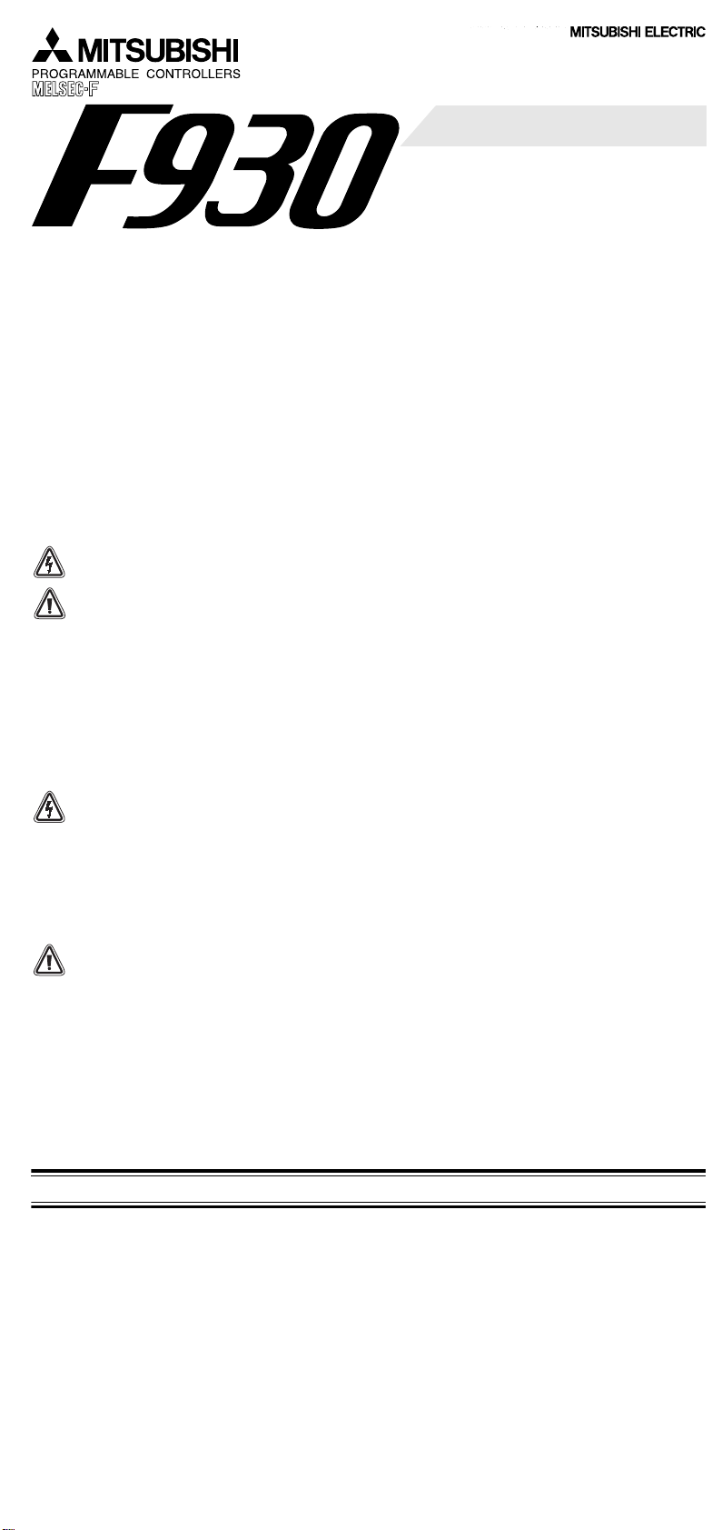
2. Outline
FX or A
Series PC
Program
connector
F930GOT
main body
The F930GOT is designed to be mou nted on the ou tside surface of a
control or operation panel and connected to the programming port of
an FX or A Series PLC (excluding A0J2 PLC) housed inside the panel.
The F930GOT can be directly connected to the CPU , a PLC other than
in the MELSEC Series or a micro computer board by means of a
computer link connection.
Monitoring and changing data devices in the PLC is possible using the
F930GOT.
Display screens can be created, using either of the following:
• Screen creation software for GOT-A and F900 Series
SWoD5C-GOTR-PACK-E (V er. H or later, manufactured in May,
1999 or later) ("o" indicates "1" or larger.)
• Screen creation software for DU and F900 Series
FX-PCS-DU/WIN-E (Ver. 2.20 or later, manufactured in October,
1999 or later)
3. Additional Products and Options
Options
Product name Model name Specifications
2NC
Battery FX
Backlight F9GT-30LTB Replacement backlight for F930GOT LC Display
Screen protec-
tion sheet
Connection cables
Product name Model name Cable length Specifications
Connection
cables:
F930GOT to
PLC
Data transfer
cable
F930GOT and
personal
computer
Software
Product name Model name Specifications
Screen
creation
software
-32BL To back up current time and alarm history
F9GT-30PSC
Transparent protectiv e sheet (for F930GOT, without logo),
five sheets in one set
FX-50DU-CAB0 3m
FX-50DU-CAB0-1M 1m
FX-50DU-CAB0-10M 10m
FX-50DU-CAB0-20M 20m
For direct connection between F930GOT
0S
and FX
/ FX0N / FX2N / FX
FX-50DU-CAB0-30M 30m
FX-40DU-CAB 3m
FX-40DU-CAB-10M 10m
FX-40DU-CAB-20M 20m
For direct connection between F930GOT
1
/ FX2 / FX2C PLC
and FX
FX-40DU-CAB-30M 30m
2
-232CAB-1 3m
F
FX-232CAB-1 3m
FX-232CAB-2 3m
SW1D5C-GOTR-PACK-E
FX-PCS-DU/WIN-E
CD-ROM Ver. H or later for Windows95 / Windows98 /
Windows NT 4.0
3.5-inch FD for system startup Ver. 2.20 or later for
Windows95 / Windows98 / Windows NT 4.0
D-Sub 9 pin female to D-Sub 25 pin female
D-Sub 9 pin female to D-Sub 9 pin female
D-Sub 9 pin female to Half pitch 14 pin
2NC
PLC
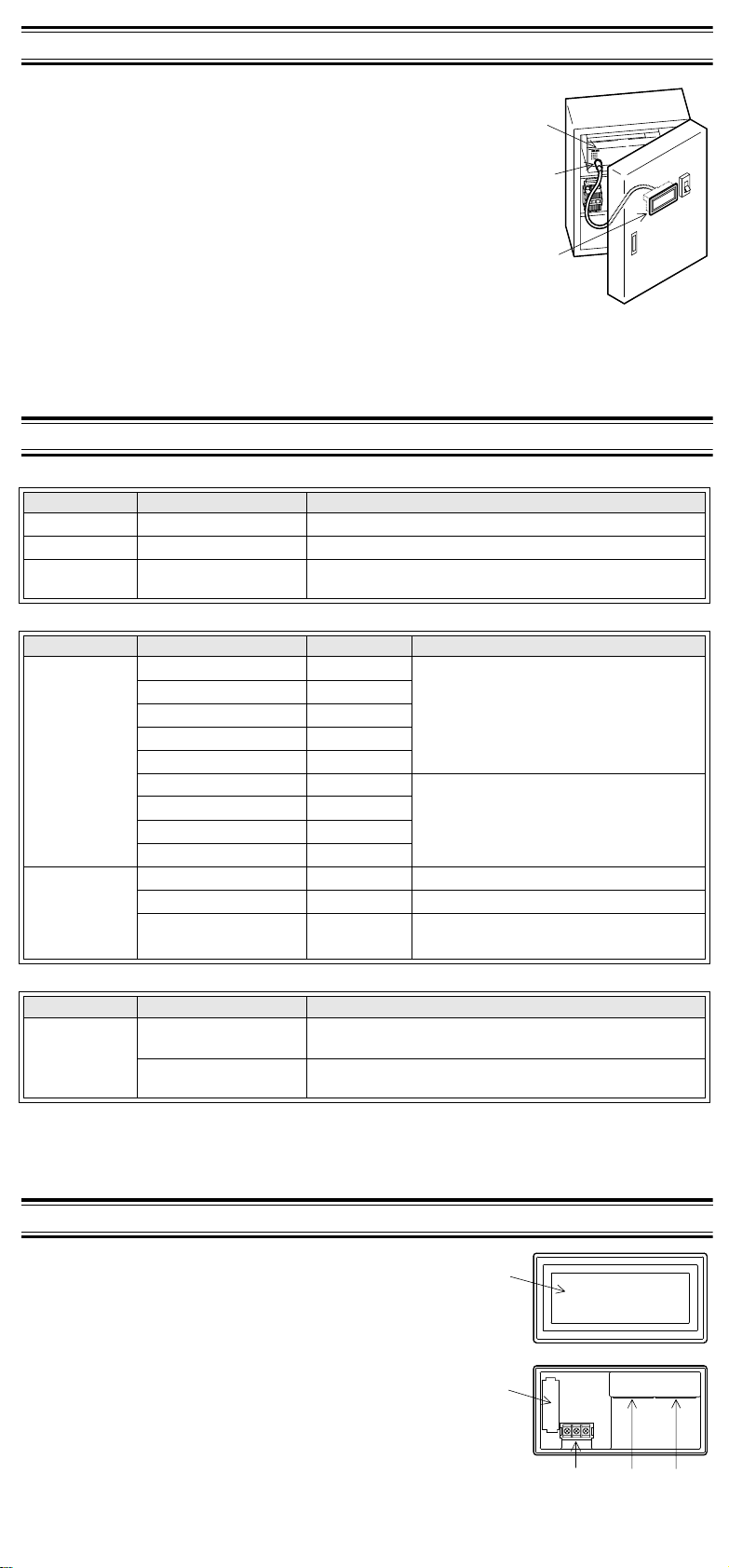
4. Component Names
The name of each component of the F930GOT is described below.
• Front panel
•
Display
For details, refer to "8. Specifications".
• Rear panel
‚
Battery FX
For details, refer to "7. Maintenance (Replacement of battery)".
ƒ
Power terminals: 24V DC, for grounding
„
RS-422 interface
D-sub, 9-pin, female connector
Used for communication with PLC
…
RS-232C interface
D-sub, 9-pin, male connector
Used to transfer screen data and for computer link connection
2NC
-32BL to back up alarm history and current time
5. Installation
Cautions on installation
• Do not mount the F930GOT in an environment that contains dust, soot corrosive or conducive
dust, corrosive or flammable gas, or expose the unit to high temperatures, de w condensation,
rain and wind or impact and vibration.
If the F930GOT is used in such a place, electrical shock, fire, malfunction, damages or
deterioration may be caused.
• Never drop cutting chips and electric wire chips into the ventilation window of the F930GOT
when drilling screw holes or performing wiring. Such chips may cause fire, failure or
malfunction.
• Make sure that the power is turned off, before securely connecting any cables. Poor
connection may cause malfunction.
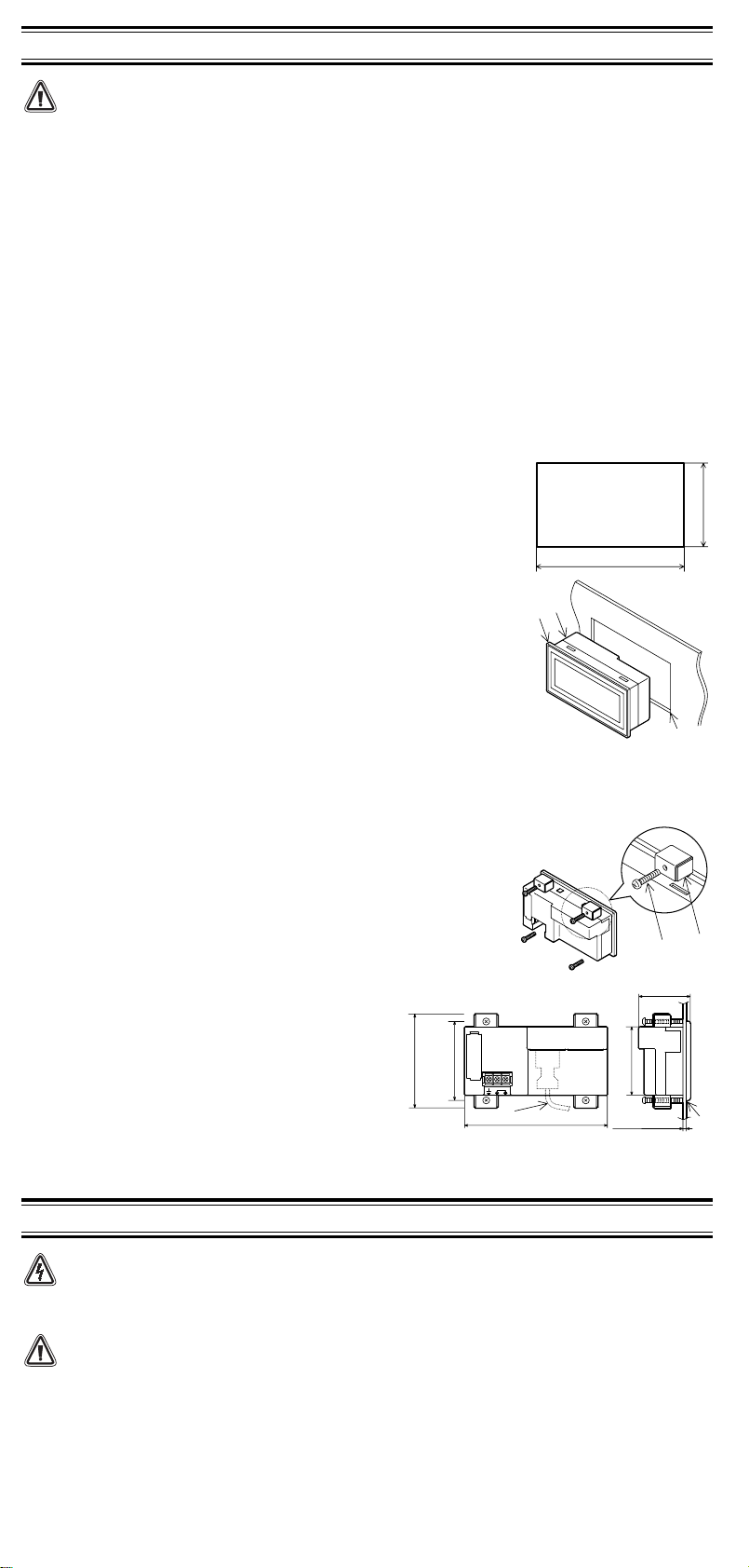
The F930GOT is designed to be mounted in a panel. Install it using the following procedure.
1) Preparing the panel surface.
On the panel surface, cut a rectangular mounting slot of the
dimensions shown on the right.
At this time, space of 10 mm is required at each of the top and the
bottom of the slot, inside the panel for metal fixtures as shown in "(4)
Dimensions required inside the panel for installation".
* Make sure that the thickness of the panel surface is no thicker than
5 mm.
2) Inserting the F930GOT into the panel surface
Attach the packing seal to the F930GOT, and insert the F930GOT
from the front face of the panel surface.
•
F930GOT
‚
Packing seal
ƒ
Mounting slot
Slot to be cut
on panel
137
+1
0
Unit: mm
+1
0
66
3) Fixing the F930GOT
Put hooks of the metal fix tures (s upplied) in to th e moun ting hook
holes in the F930GOT. Tighten mounting bolts (also supplied) until
the F930GOT is securely fixed.
Fix mounting bolts in all four positions, above and below the GOT.
•
Metal fixture
‚
Clamping bolt
* Make sure to tighten the clamping bolts with a torque of 0.3 to
0.5 N m.
4) Dimensions required inside the panel for
installation
When installing the F930GOT, make sure that the
inside dimensions shown on the right are
available.
•
PLC connection cable
‚
Packing seal
of metal fixture)
85(Outside dimension
between
75(Dimension
screw centers)
24VDC
136
6. Wiring
Cautions on wiring
• Make sure the unit is ‘powered down’ before starting installation or wiring.
Damage or personal injury may otherwise be caused
• Insure correct termination of DC power source, incorrect connection may result in unit failure
or the F930GOT being burnt.
• Attach a fuse of 2 A to the 24V DC power supply.
• Perf orm Class 3 grounding with an electric wire of at least 1.25 mm
Never perform common grounding of the F930GOT and a strong power system.
2
.
Enlarged view
49
65
5mm or less
 Loading...