

F920GOT-BBD5-K-E
PLC
Programming
port
GOT
35.5(1.40")
5(0.20")
106(4.17")
134(5.28")
a)
b)
d)
c)
Front panel
Rear panel (with mounting bracket and tightening bolt)
F920GOT-BBD-K-E
Installation Manual
JY997D02201G
This manual contains text, diagrams and explanations which will guide the reader in the correct installation, safe use and
operation of the F920GOT-BBD5-K-E, F920GOT-BBD-K-E and should be read and understood before attempting to
install or use the unit. Further information can be found in the associated manuals list below.
Specifications are subject to change without notice
Guidelines for the Safety of the User and Protection of the F920GOT-BBD5-K-E,
F920GOT-BBD-K-E
This manual has been written to be used by trained and competent personnel. The definition of such a person or persons
is as follows:
a) Any engineer using the product associated with this manual, should be of a competent nature, trained and
qualified to the local and national standards. These engineers should be fully aware of all aspects of safety with
regards to automated equipment.
b) Any commissioning or service engineer must be of a competent nature, trained and qualified to the local and
national standards.
c) All operators of the completed equipment (see note) should be trained to use that product in a safe manner in
compliance to established safety practices.
Note:
The term ‘completed equipment’ refers to a third party constructed device which contains or uses the product
associated with this manual.
Note’s on the Symbols Used in this Manual
At various times through out this manual certain symbols will be used to highlight points of information which are intended
to ensure the users personal safety and protect the integrity of equipment.
1) Indicates that the identified danger
WILL
cause physical and proper ty damage.
2) Indicates that the identified danger could
• Under no circumstances will Mitsubishi Electric be liable or responsible for any consequential damage that may arise
as a result of the installation or use of this equipment.
• All examples and diagrams shown in this manual are intended only as an aid to understanding the text, not to
guarantee operation. Mitsubishi Electric will accept no responsibility for actual use of the product based on these
illustrative examples.
• Please contact a Mitsubishi Electric distributor for more information concerning applications in life critical situations
or high reliability.
POSSIBLY
cause physical and proper ty damage.
Associated Manuals
Manual Name Manual Number Description
F920GOT-BBD5-K-E,
F920GOT-BBD-K-E
|
Installation Manual
GOT-F900
OPERATION MANUAL
~
(describes GT Designer2)
GOT-F900 Series
~
Operation Manual
GOT-F900 Series
Hardware Manual
~
(connection diagram)
SWD5C-GOTR-PACK
|
Operating Manual
GT Designer2 Version 1
|
Operating Manual
GT Designer2 Version 1
|
Reference Manual
FX-PCS-DU/WIN-E
|
SOFTWARE MANUAL
Necessary manual
~
Either manual is necessary.
|
Refer to the manual of the connected programmable controller for further details concerning that unit.
JY997D02201
(This manual)
JY997D09101
(separate volume)
JY992D94701
(separate volume)
JY992D94801
(separate volume)
(included with screen
creation software)
(PDF files on CD-ROM
included with screen
creation software)
(PDF files on CD-ROM
included with screen
creation software)
JY992D68301
(included with screen
creation software)
Describes the hardware such as specifications, wiring and
installation of the F920GOT-BBD5-K-E and F920GOT-BBDK-E.
Describes the operation and use of the GOT-F900 Series
graphic operation terminals and GT Designer2.
Describes the operation and use of the GOT-F900 Series
graphic operation terminals, GT Designer and FX-PCS-DU/
WIN-E.
Describes wiring and installation of the GOT-F900 Series
graphic operation terminals.
Describes the operating procedures of the screen creation
software. (See the HELP file in the software.)
Describes the operation method of GT Designer2
(SWD5C-GTD2-J), data transfer to the GOT-900 Series,
etc.
Describes the specifications, contents of setting, etc. of
each object function used in GT Designer2 (SWD5CGTD2-J).
Describes the operation of FX-PCS-DU/WIN-E screen
creation software.
1. Introduction
PLC
Programming
port
GOT
35.5(1.40")
5(0.20")
106(4.17")
134(5.28")
a)
b)
d)
c)
Front panel
Rear panel (with mounting bracket and tightening bolt)
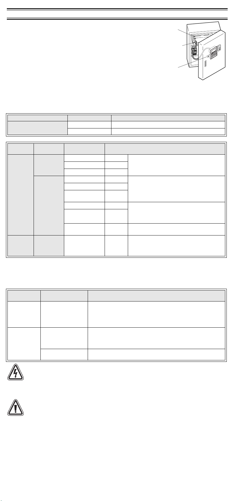
1) The F920GOT-BBD5-K-E and F920GOT-BBD-K-E (hereafter called “GOT”)
are to be mounted on the face of a control or operations panel, and
connected to the programming port (CPU port) of a PLC.
2) Various devices can be monitored and PLC data changed through the
screens in the GOT.
3) Using PLC programming software, FX Series PLC user programming can be
uploaded, downloaded and monitored via the GOT.
4) The F920GOT-BBD5-K-E is driven by 5V DC power supply (from the PLC
through a communication cable). The F920GOT-BBD-K-E is driven by a 24V
DC power supply.
5) The F920GOT-BBD5-K-E can be connected to the FX, A, QnA and Q Series
PLC.
The F920GOT-BBD-K-E can be connected to the FX, A, QnA and Q Series
PLC, PLC manufactured by another company and micro computer board.
For further details concerning applicable PLCs and connections to the PLC, refer to the GOT-F900 Series Hardware
Manual (Connection Diagram) offered as a separate volume.
1.1 Product Lists
GOT Main Unit
Product Name Model Name Specifications
Graphic Operation Terminal
Optional communication cable
Product
Name
Classification Model Name Specifications
F920GOTBBD5-K-E
PLC
connection
cable
F920GOTBBD-K-E
Screen data
transfer
cable
• In addition to the connections shown above, the F920GOT-BBD5-K-E can be connected to the A, QnA and Q Series
PLC, and the F920GOT-BBD-K-E can be connected to via computer link to a PLC manufactured by Mitsubishi, PLC
F920GOTBBD5-K-E
and F920GOTBBD-K-E
manufactured by another manufacturers and micro computer board.
For further details concerning connectable equipment and communication cables, refer to the GOT-F900 Series
Hardware Manual [Connection] offered as a separate volume.
Optional screen creation software
Product
Name
For F920GOTBBD5-K-E and
F920GOT-BBDK-E
GT Designer 2
SWD5C-GTD2-E (
indicates the version.)
GT Designer
SWD5C-GOTR-
F920GOT-BBD5K-E
PACKE ( indicates the
version .)
FX-PCS-DU/WIN-E
Caution
During abnormal communication (including cable breakage) when monitoring within the GOT,
communication between the GOT and programmable controller CPU is interrupted and it is impossible to
operate keys or devices in the PLC via the GOT.
Communication and operation resumes when the GOT system is correctly configured.
DO NOT configure the emergency stop or safety features through the GOT, and be sure that there will be
no adverse consequences in the event of a GOT - PLC communications malfunction.
Note
• Do not lay signal cables near high voltage power cables or allow them to share the same trunking duct.
Otherwise effects of noise or surge induction are likely to occur. Keep a safe distance of more than 100
mm away from these wires.
• Operate switches on the panel by hand.
DO NOT use excessive force, or attempt to operate them with hard or pointed objects.
The tip of a screw driver, pen or similar objects for example may break the screen.
Connectable PLC units differ for the F920GOT-BBD5-K-E and the F920GOT-BBD-K-E.
Further information can be found in GOT-F900 series Hardware Manual [Connection].
F920GOT-BBD5-K-E Graphic operation ter minal main unit
F920GOT-BBD-K-E Graphic operation terminal main unit
FX-50DU-CAB0 3m (9’10”) Communication cable (GOT ↔ CPU port in FX
FX-50DU-CAB0/EN 3m (9’10”)
FX-50DU-CAB0-1M 1m (3’3”)
, FX0N, FX1N, FX2N or FX
FX
1S
Cable length is 3m (9' 10").
Use FX-50DU-CAB0/EN for compliance to EC EMC.
series PLC)
2NC
FX-50DU-CAB0 3m (9’10”) Communication cable (GOT ↔ CPU port in FX
, FX0N, FX1N, FX2N or FX
FX
FX-50DU-CAB0/EN 3m (9’10”)
FX-50DU-CAB0-**M
Described
on right
FX-40U-CAB 3m (9’10”) Communication cable (GOT ↔ CPU port in A, QnA
FX-40DU-CAB0-**M
Described
on right
QC30R2 3m (9’10”)
FX-232CAB-1 3m (9’10”)
1S
(**M is cable length 1M:1m(3’3”), 10M:10m(32’9”),
20M:20m(65’7”), 30M:30m(98’5”).
Use FX-50DU-CAB0/EN for compliance to EC EMC.
series PLC)
(**M is cable length 10M:10m(32’9”),
20M:20m(65’7”), 30M:30m(98’5”).
Communication cable (GOT ↔ CPU port in Q series
PLC)
Data exchange cable (GOT ↔ Personal computer
<9-pin D-sub>)
series PLC)
2NC
Model Name Specifications
Software for GOT-F900 and GOT-A900 Series (for Windows)
In F920GOT-BBD5-K-E, SW1D5C-GTD2-E Version 1.00A or later is
available.
In F920GOT-BBD-K-E, SW1D5C-GTD2-E Version 1.02C or later is
available.
Software for GOT-F900 and GOT-A900 Series (for Windows)
SW5D5C-GOTR-PACK-E SW5-26C version (Version 5.26C) or later
Software for GOT-F900 Series (for Windows)
SW0PC-FXDU/WIN-E Version 2.70 or later
,
0S
,
0S
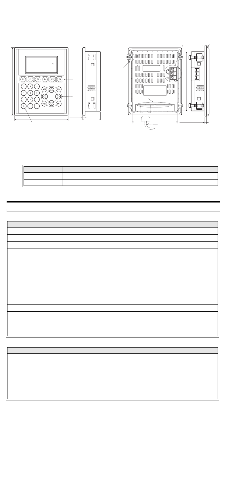
1.2 Dimensions and Each Part Name [Both F920GOT-BBD5-K-E and F920GOT-BBD-K-E
35.5(1.40")
5(0.20")
106(4.17")
134(5.28")
a)
b)
d)
c)
Front panel
Rear panel (with mounting bracket and tightening bolt)
(Power terminals is excluded).]
Dimensions: mm (inches) Mass (Weight): 0.3 kg (0.66 lbs)
Accessory: Mounting brackets, Tightening bolt (M4, 4 bolts), Packing seal for dust and water resistance
e)
g)
COM0 RS422
90(3.54")
1) Front panel
a) Display b) Function keys c) Cursor keys d) 0 to 9 keys
2) Rear panel
e) Mounting bracket and tightening bolt (accessory)
f) Power terminals (Not provided for the F920GOT-BBD5-K-E)
g) Communication ports
Port Description
COM0 RS-422 RS-422 port for connecting PLC (FX, A, QnA) <9-pin D-sub>
COM1 RS-232C RS-232C port for connecting a personal computer or PLC (Q) <9-pin D-sub>
h) Communication cable (optional)
i) Packing seal (accessory)
2. Specifications
2.1 General Specifications (F920GOT-BBD5-K-E and F920GOT-BBD-K-E)
Item Specifications
Operating Temperature 0 ~ 50 °C (32 ~ 122 °F)
Storage Temperature -20 ~ 60 °C (-4 ~ 140 °F)
Humidity 35 ~ 85% Relative Humidity, No condensation
Operating atmosphere
Vibration Resistance
- intermittent vibration
Vibration Resistance
- Continuous vibration
Shock Resistance
Noise Immunity 1000 Vp-p, 1µ second, 30 ~ 100 Hz, tested by noise simulator
Dielectric Withstand
Vo lt ag e
Insulation Resistance 5 MΩ > at 500 V DC, tested between power terminals and ground
Protection IP65f level (Front panel only)
2.2 Power Supply Specifications
Model Name Specifications
F920GOTBBD5-K-E
F920GOTBBD-K-E
Supply voltage : 5V DC ±5% (supplied from PLC through communication cable)
Current consumption : 220mA/5V DC while backlight is ON, 180mA/5V DC while backlight is OFF
Supply voltage : 24V DC+10%-15% (externally supplied through power terminals)
Power ripple : 220 mV or less
Current consumption : 80mA/24V DC while backlight is ON, 70mA/24V DC while backlight is OFF
Fuse : Built-in (It cannot be replaced.)
Allowable instantaneous power interr uption:
Grounding : Grounding resistance: 100Ω or less
Must be free of lamp black, corrosive gas, flammable gas, or excessive amount of
electroconductive dust par ticles and must be no direct sunlight. (Same as for saving)
10 ~ 57 Hz: 0.075 mm Half Amplitude
57 ~ 150 Hz: 9.8 m/s
2
Acceleration
Sweep Count for X, Y, Z: 10 times (80 min. in each direction)
10 ~ 57 Hz: 0.035 mm Half Amplitude
57 ~ 150 Hz: 4.9 m/s
2
Acceleration
Sweep Count for X, Y, Z: 10 times (80 min in each direction)
2
147m/s
Acceleration,
3 times in each direction X, Y, and Z
500 V AC > 1 min, tested between power terminals and ground
Less than 5 ms (Continuous operation is assured.)
COM1 RS232C
h)
f)
118(4.65")
5(0.20") or less
i)

HEAD OFFICE
HIMEJI WORKS
: TOKYO BUILDING, 2-7-3 MARUNOUCHI, CHIYODA-KU, TOKYO 100-8310, JAPAN
: 840, CHIYODA CHO, HIMEJI, JAPAN
2.3 Screen Hardware Specifications (F920GOT-BBD5-K-E and F920GOT-BBD-K-E)
Crimp-style
terminal
Terminal
screw
Terminal
C
i
l
T
i
l
E
F F F
FX-50DU-CAB0
110 (4.33")
GOT units
Programmable
Controller
Unit: mm (inches)
Items Specifications
Display Device STN monochrome liquid crystal display
Resolution 128 × 64 (dot), 16 characters × 4 lines
Dot Pitch 0.47 mm (0.019") Horizontal × 0.47 mm (0.019") Vertical.
Effective Display Size 60 mm (2.36") × 30 mm (1.18") 3(2.64" inch) type
Number of Colors 2 colors (White and Blue)
Life of liquid crystal display Approximately 50,000 hours (Operating temperature: 25 °C/77°F)
Backlight LED (White and Red)
Keypad 26 keys (0 to 9 keys, Cursor keys, Function keys, SET key, DEV key, ESC key, ENT key)
Interface
Number of Screens
RS-422 RS-422 (COM0)
RS-232C RS-232C (COM1)
User screen: 500 screens or less
System screen: Allocated screens No. 1001-1030.
User Memory Flash memory 128 KB (built-in)
• Bright dots (always lit) and dark dots (unlit) may appear on a liquid crystal display panel. It is
impossible to completely avoid this symptom, as the liquid crystal display comprises of a great
number of display elements.
Flickers may be observed depending on the display color.
Please note that these dots appear due to its characteristic and are not caused by product defect.
• When the same screen is displayed for a long time, an incidental color or partial discoloration is
generated on the screen due to heat damage, and it may not disappear.
3. Installation
Note
• Do not mount the GOT in an environment that contains dust, corrosive soot, conducive dust, corrosive
or flammable gas, or expose the unit to high temperatures, dew condensation, direct sunlight, rain and
wind or impact and vibration.
If the GOT is used in such a place, electrical shock, fire, malfunction, damages or deterioration may
occur.
• Never drop cutting chips or electric wire chips into the ventilation window of the GOT when drilling
screw holes or performing wir ing. Such chips may cause fire, failure or malfunction.
• Make sure that the power is turned off, before securely connecting any cables. Poor connection may
The GOT is designed to be mounted in a panel. Install it using the following procedure:
The installation method and the dimensions required inside the panel are identical for the F920GOT-BBD5-K-E and
F920GOT-BBD-K-E.
Illustrations of the F920GOT-BBD-K are used in the explanation for this manual.
1) Preparing the panel surface.
On the panel surface, cut a rectangular mounting slot with the dimensions shown below.
A space of 10 mm is required for the right and left sides of the slot and inside the panel for metal fixtures as shown in
“5) Inner panel installation dimensions”.
cause malfunction.
(See Figure A)
Note
Make sure that the thickness of the panel surface is no more than 5 mm (0.20").
2) Inserting the GOT into the panel surface
Attach the packing seal to the GOT, and insert the GOT from the front face of the panel surface.
(See Figure B)
a) Packing seal
b) GOT
c) Mounting slot
3) Fixing the GOT
(See Figure C)
Attach the hooks of the mounting brackets (supplied) in to the mounting holes of the GOT. Tighten mounting bolts
(also supplied) until the GOT is securely fixed.
Fix mounting bolts in all four positions, right and left of the GOT.
a) Clamping bolt
b) Mounting bracket
Note
Tighten the clamping bolts with a torque of 0.18 to 0.22 Nm.
4) Peeling of the protective sheet
Peel off the protective sheet on the surface of the product before use.
5) Inner panel installation dimensions
(See figure D)
.
When installing the GOT, make sure the inner dimensions shown below are available.
a) PLC connection cable
b) Packing seal
A
92(3.62")
Slot to be
cut on panel
+1(+0.04")
119(4.69")
+1(+0.04")
0
Unit: mm(inches)
B
b)
a)
0
c)
C
24VDC
b)
a)

HEAD OFFICE
HIMEJI WORKS
: TOKYO BUILDING, 2-7-3 MARUNOUCHI, CHIYODA-KU, TOKYO 100-8310, JAPAN
: 840, CHIYODA CHO, HIMEJI, JAPAN
D
Crimp-style
terminal
Terminal
screw
Terminal
Cri
T
l
E
F F F
FX-50DU-CAB0
110 (4.33")
GOT units
Programmable
Controller
Unit: mm (inches)
134(5.28")
7(0.28")
10(0.39")
86(3.39")
10(0.39")
109(4.29")
99(3.90")
COM0 RS422
COM1 RS232C
10(0.39")
24VDC
5(0.20")
10
(0.39")
86(3.39")
10
(0.39")
35.5(1.40")
5(0.20")
5(0.20")
70(2.76")
(cable)
5(0.20") or less
a)
7(0.28")
Unit: mm(inches)
b)
4. Power Supply Wiring (F920GOT-BBD-K-E)
Cautions
• Cut OFF all external phases of the power supply before installation or wiring to avoid electric shock or
serious damage to the product.
Note
• Wire the DC power supply to the dedicated terminals as descr ibed in this manual. Wiring an AC power
supply will cause serious damage to the product.
• Attach a 2A fuse to the 24V DC power supply. Correctly connect the + and - terminals of the DC power
supply as descried in this manual.
Reverse connection of the power supply may cause failure.
• Perform grounding (resistance: 100Ω or less) with an electric wire of 1.25 mm
terminal of the GOT.
Never perform common grounding of the GOT and a strong power system.
The power for the F920GOT-BBD-K-E is externally supplied through the power ter minals provided on the rear face.
(The power for the F920GOT-BBD5-K-E is supplied from the PLC through a communication cable.)
The power of the GOT is supplied from the PLC or an external power supply.
• Connection example
1) When supplying the power from the FX Series PLC
Connect the power terminals provided on the rear face
of the GOT to the 24V DC service power supply of the
PLC base or extension unit.
Grounding
resistance
Ω
100
or less
2) When supplying the power from an external power
supply
Connect the power terminals provided on the rear face
of the GOT to the 24V DC terminals of the external
power supply.
2A
Grounding
resistance
Ω
or less
100
2
or more to the ground
Grounding
resistance
100Ω or less
Externa l
power
supply
2A
24+ COM - +
PLC GOT
24V
DC
24+ COM - +
PLC GOT
24V
DC
Crimp-style terminal When wiring 1 wire per terminal When wiring 2 wires per terminal
6.2 mm(0.24")
or less
6.2 mm (0.24")
or less
3.2(0.13")
φ
3.2(0.13")
φ
ermina
screw
Terminal
mp-style
terminal
Cautions on connection
The current consumption of the GOT is 80mA/24V DC (while the backlight is ON). When supplying power from the 24V
DC service power supply of the FX Series PLC main unit or extension unit, consider the capacity of the service power
supply of the base or extension unit and the total current supplied to proximity switches, extension blocks and special
blocks. If the total current including the power supplied to the GOT exceeds the capacity of the service power supply,
supply the power to the GOT from the external power supply.
• Even if instantaneous power interruption of less than 5 ms occurs, the GOT continues to operate. When power
interruption for a considerable period of time or voltage drop occurs, the GOT stops its operation. However, when the
power supply is recovered, the GOT automatically restarts its operation. (The screen displayed just after recovery is
determined by the working environment originally set.)
2
• When wiring the power supply, use electric wires of 0.75 mm
or more to avoid voltage drop. Use crimp-style
terminals for M3, and securely tighten them with a tightening torque of 0.5 to 0.8 N·m to avoid troubles.
5. Maintenance
Cautions
Never disassemble or modify the GOT. Disassembly or modification may cause failure, malfunction or fire.
For repair, please, contact a service representative.
Note
Make sure to turn OFF the power, before connecting/disconnecting cables.
If you connect/disconnect cables while the power is turned on, failure or malfunction may be caused.
A backlight lithium battery is not supplied with the GOT. The Liquid Crystal Display has a service life of approximately
50,000 hours.
When repairing the Liquid Crystal Display, please, contact a service representative.

HEAD OFFICE
HIMEJI WORKS
: TOKYO BUILDING, 2-7-3 MARUNOUCHI, CHIYODA-KU, TOKYO 100-8310, JAPAN
: 840, CHIYODA CHO, HIMEJI, JAPAN
Notification of CE marking
E
F F F
FX-50DU-CAB0
110 (4.33")
GOT units
Programmable
Controller
Unit: mm (inches)
The following products have shown compliance through direct testing (to the identified standards) and design analysis
(forming a technical construction file) to the European Directive for Electromagnetic Compatibility (2004/108/EC) when
used as directed by the appropriate documentation.
• This product is designed for use in industrial applications.
• Manufactured by: Mitsubishi Electric Corporation
• Manufactured at: Mitsubishi Electric Corporation Himeji Works
• Authorized Representative in the European Community: Mitsubishi Electric Europe B.V.
Type : Programmable Controller (Open Type Equipment)
Models : MELSEC GOT series products, identified here, manufactured from
December 1st, 2009 F920GOT-BBD5-K-E
EN61131-2 : 2007
Programmable controllers
- Equipment, requirement and tests
For more details please contact the local Mitsubishi Electric sales site.
2-7-3 Marunouchi, Chiyoda-ku, Tokyo 100-8310 Japan
840 Chiyoda-machi, Himeji, Hyogo 670-8677 Japan
Gothaer Str. 8, 40880 Ratingen, Germany
F920GOT-BBD-K-E
Standard Remark
Compliance with all relevant aspects of the standard.
EMI
(Radiated Emissions)
Compliance with all relevant aspects of the standard.
EMS
(ESD, RF electromagnetic field, EFTB, Surge, RF conducted
disturbances and Power frequency magnetic field)
Notes Regarding the Use of GOT Units
General notes on the use of Communication Cables
Any device which utilizes a data communication function is susceptible to the wider effects of local EMC noise. Therefore,
when installing any communication cables care should always be taken with the routing and location of those cables. The
GOT units identified on the previous page are compliant with the EMC requirement when the following communication
cables are used:
GOT Units Existing Cables User Made Cables
F920GOT-BBD5-K-E
F920GOT-BBD-K-E
When using the FX-50DU-CAB0/EN cable the Earth Strap must be connected to a suitable earth point.
Ex. 1
E = Additional earth strap connected to the cables shield. Free end of the earth strap must be connected to an earth
point.
F = Ferrite core
Ex. Tokin - ESD-R-17S or similar
FX-50DU-CAB0/EN
FX-50DU-CAB0 modified as
shown in EX.1
and
This cable need to be independently tested by the
user to demonstrate EMC compatibility when they
are used with Mitsubishi GOT units and
Programmable Controllers.
Warranty
Mitsubishi will not be held liable for damage caused by factors found not to be the cause of Mitsubishi;
opportunity loss or lost profits caused by faults in the Mitsubishi products; damage, secondary damage,
accident compensation caused by special factors unpredictable by Mitsubishi; damages to products
other than Mitsubishi products; and to other duties.
For the detailed warranty, refer to the GOT-F900 Series HARDWARE MANUAL [CONNECTION].
Manual number: JY997D02201
Manual revision: G
Date : Aug. 2010

F920GOT-BBD5-K-E
PLC
Programming
port
GOT
35.5(1.40")
5(0.20")
106(4.17")
134(5.28")
a)
b)
d)
c)
Front panel
Rear panel (with mounting bracket and tightening bolt)
F920GOT-BBD-K-E
Installation Manual
JY997D02201G
This manual contains text, diagrams and explanations which will guide the reader in the correct installation, safe use and
operation of the F920GOT-BBD5-K-E, F920GOT-BBD-K-E and should be read and understood before attempting to
install or use the unit. Further information can be found in the associated manuals list below.
Specifications are subject to change without notice
Guidelines for the Safety of the User and Protection of the F920GOT-BBD5-K-E,
F920GOT-BBD-K-E
This manual has been written to be used by trained and competent personnel. The definition of such a person or persons
is as follows:
a) Any engineer using the product associated with this manual, should be of a competent nature, trained and
qualified to the local and national standards. These engineers should be fully aware of all aspects of safety with
regards to automated equipment.
b) Any commissioning or service engineer must be of a competent nature, trained and qualified to the local and
national standards.
c) All operators of the completed equipment (see note) should be trained to use that product in a safe manner in
compliance to established safety practices.
Note:
The term ‘completed equipment’ refers to a third party constructed device which contains or uses the product
associated with this manual.
Note’s on the Symbols Used in this Manual
At various times through out this manual certain symbols will be used to highlight points of information which are intended
to ensure the users personal safety and protect the integrity of equipment.
1) Indicates that the identified danger
2) Indicates that the identified danger could
• Under no circumstances will Mitsubishi Electric be liable or responsible for any consequential damage that may arise
as a result of the installation or use of this equipment.
• All examples and diagrams shown in this manual are intended only as an aid to understanding the text, not to
guarantee operation. Mitsubishi Electric will accept no responsibility for actual use of the product based on these
illustrative examples.
• Please contact a Mitsubishi Electric distributor for more information concerning applications in life critical situations
or high reliability.
Associated Manuals
Manual Name Manual Number Description
F920GOT-BBD5-K-E,
F920GOT-BBD-K-E
|
Installation Manual
GOT-F900
OPERATION MANUAL
~
(describes GT Designer2)
GOT-F900 Series
~
Operation Manual
GOT-F900 Series
Hardware Manual
~
(connection diagram)
SWD5C-GOTR-PACK
|
Operating Manual
GT Designer2 Version 1
|
Operating Manual
GT Designer2 Version 1
|
Reference Manual
FX-PCS-DU/WIN-E
|
SOFTWARE MANUAL
Necessary manual
~
Either manual is necessary.
|
Refer to the manual of the connected programmable controller for further details concerning that unit.
JY997D02201
(This manual)
JY997D09101
(separate volume)
JY992D94701
(separate volume)
JY992D94801
(separate volume)
(included with screen
creation software)
(PDF files on CD-ROM
included with screen
creation software)
(PDF files on CD-ROM
included with screen
creation software)
JY992D68301
(included with screen
creation software)
WILL
cause physical and proper ty damage.
POSSIBLY
cause physical and proper ty damage.
Describes the hardware such as specifications, wiring and
installation of the F920GOT-BBD5-K-E and F920GOT-BBDK-E.
Describes the operation and use of the GOT-F900 Series
graphic operation terminals and GT Designer2.
Describes the operation and use of the GOT-F900 Series
graphic operation terminals, GT Designer and FX-PCS-DU/
WIN-E.
Describes wiring and installation of the GOT-F900 Series
graphic operation terminals.
Describes the operating procedures of the screen creation
software. (See the HELP file in the software.)
Describes the operation method of GT Designer2
(SWD5C-GTD2-J), data transfer to the GOT-900 Series,
etc.
Describes the specifications, contents of setting, etc. of
each object function used in GT Designer2 (SWD5CGTD2-J).
Describes the operation of FX-PCS-DU/WIN-E screen
creation software.
1. Introduction
1) The F920GOT-BBD5-K-E and F920GOT-BBD-K-E (hereafter called “GOT”)
are to be mounted on the face of a control or operations panel, and
connected to the programming port (CPU port) of a PLC.
2) Various devices can be monitored and PLC data changed through the
screens in the GOT.
3) Using PLC programming software, FX Series PLC user programming can be
uploaded, downloaded and monitored via the GOT.
4) The F920GOT-BBD5-K-E is driven by 5V DC power supply (from the PLC
through a communication cable). The F920GOT-BBD-K-E is driven by a 24V
DC power supply.
5) The F920GOT-BBD5-K-E can be connected to the FX, A, QnA and Q Series
PLC.
The F920GOT-BBD-K-E can be connected to the FX, A, QnA and Q Series
PLC, PLC manufactured by another company and micro computer board.
For further details concerning applicable PLCs and connections to the PLC, refer to the GOT-F900 Series Hardware
Manual (Connection Diagram) offered as a separate volume.
1.1 Product Lists
GOT Main Unit
Product Name Model Name Specifications
Graphic Operation Terminal
Optional communication cable
Product
Name
Classification Model Name Specifications
F920GOTBBD5-K-E
PLC
connection
cable
F920GOTBBD-K-E
Screen data
transfer
cable
• In addition to the connections shown above, the F920GOT-BBD5-K-E can be connected to the A, QnA and Q Series
PLC, and the F920GOT-BBD-K-E can be connected to via computer link to a PLC manufactured by Mitsubishi, PLC
F920GOTBBD5-K-E
and F920GOTBBD-K-E
manufactured by another manufacturers and micro computer board.
For further details concerning connectable equipment and communication cables, refer to the GOT-F900 Series
Hardware Manual [Connection] offered as a separate volume.
Optional screen creation software
Product
Name
For F920GOTBBD5-K-E and
F920GOT-BBDK-E
GT Designer 2
SWD5C-GTD2-E (
indicates the version.)
GT Designer
SWD5C-GOTR-
F920GOT-BBD5K-E
PACKE ( indicates the
version .)
FX-PCS-DU/WIN-E
Caution
During abnormal communication (including cable breakage) when monitoring within the GOT,
communication between the GOT and programmable controller CPU is interrupted and it is impossible to
operate keys or devices in the PLC via the GOT.
Communication and operation resumes when the GOT system is correctly configured.
DO NOT configure the emergency stop or safety features through the GOT, and be sure that there will be
no adverse consequences in the event of a GOT - PLC communications malfunction.
Note
• Do not lay signal cables near high voltage power cables or allow them to share the same trunking duct.
Otherwise effects of noise or surge induction are likely to occur. Keep a safe distance of more than 100
mm away from these wires.
• Operate switches on the panel by hand.
DO NOT use excessive force, or attempt to operate them with hard or pointed objects.
The tip of a screw driver, pen or similar objects for example may break the screen.
Connectable PLC units differ for the F920GOT-BBD5-K-E and the F920GOT-BBD-K-E.
Further information can be found in GOT-F900 series Hardware Manual [Connection].
F920GOT-BBD5-K-E Graphic operation ter minal main unit
F920GOT-BBD-K-E Graphic operation terminal main unit
FX-50DU-CAB0 3m (9’10”) Communication cable (GOT ↔ CPU port in FX
FX-50DU-CAB0/EN 3m (9’10”)
FX-50DU-CAB0-1M 1m (3’3”)
, FX0N, FX1N, FX2N or FX
FX
1S
Cable length is 3m (9' 10").
Use FX-50DU-CAB0/EN for compliance to EC EMC.
series PLC)
2NC
FX-50DU-CAB0 3m (9’10”) Communication cable (GOT ↔ CPU port in FX
, FX0N, FX1N, FX2N or FX
FX
FX-50DU-CAB0/EN 3m (9’10”)
FX-50DU-CAB0-**M
Described
on right
FX-40U-CAB 3m (9’10”) Communication cable (GOT ↔ CPU port in A, QnA
FX-40DU-CAB0-**M
Described
on right
QC30R2 3m (9’10”)
FX-232CAB-1 3m (9’10”)
1S
(**M is cable length 1M:1m(3’3”), 10M:10m(32’9”),
20M:20m(65’7”), 30M:30m(98’5”).
Use FX-50DU-CAB0/EN for compliance to EC EMC.
series PLC)
(**M is cable length 10M:10m(32’9”),
20M:20m(65’7”), 30M:30m(98’5”).
Communication cable (GOT ↔ CPU port in Q series
PLC)
Data exchange cable (GOT ↔ Personal computer
<9-pin D-sub>)
series PLC)
2NC
Model Name Specifications
Software for GOT-F900 and GOT-A900 Series (for Windows)
In F920GOT-BBD5-K-E, SW1D5C-GTD2-E Version 1.00A or later is
available.
In F920GOT-BBD-K-E, SW1D5C-GTD2-E Version 1.02C or later is
available.
Software for GOT-F900 and GOT-A900 Series (for Windows)
SW5D5C-GOTR-PACK-E SW5-26C version (Version 5.26C) or later
Software for GOT-F900 Series (for Windows)
SW0PC-FXDU/WIN-E Version 2.70 or later
,
0S
,
0S
1.2 Dimensions and Each Part Name [Both F920GOT-BBD5-K-E and F920GOT-BBD-K-E
(Power terminals is excluded).]
Dimensions: mm (inches) Mass (Weight): 0.3 kg (0.66 lbs)
Accessory: Mounting brackets, Tightening bolt (M4, 4 bolts), Packing seal for dust and water resistance
f)
e)
118(4.65")
g)
COM0 RS422
COM1 RS232C
90(3.54")
h)
5(0.20") or less
1) Front panel
a) Display b) Function keys c) Cursor keys d) 0 to 9 keys
2) Rear panel
e) Mounting bracket and tightening bolt (accessory)
f) Power terminals (Not provided for the F920GOT-BBD5-K-E)
g) Communication ports
Port Description
COM0 RS-422 RS-422 port for connecting PLC (FX, A, QnA) <9-pin D-sub>
COM1 RS-232C RS-232C port for connecting a personal computer or PLC (Q) <9-pin D-sub>
h) Communication cable (optional)
i) Packing seal (accessory)
2. Specifications
2.1 General Specifications (F920GOT-BBD5-K-E and F920GOT-BBD-K-E)
Item Specifications
Operating Temperature 0 ~ 50 °C (32 ~ 122 °F)
Storage Temperature -20 ~ 60 °C (-4 ~ 140 °F)
Humidity 35 ~ 85% Relative Humidity, No condensation
Operating atmosphere
Vibration Resistance
- intermittent vibration
Vibration Resistance
- Continuous vibration
Shock Resistance
Noise Immunity 1000 Vp-p, 1µ second, 30 ~ 100 Hz, tested by noise simulator
Dielectric Withstand
Vo lt ag e
Insulation Resistance 5 MΩ > at 500 V DC, tested between power terminals and ground
Protection IP65f level (Front panel only)
2.2 Power Supply Specifications
Model Name Specifications
F920GOTBBD5-K-E
F920GOTBBD-K-E
Supply voltage : 5V DC ±5% (supplied from PLC through communication cable)
Current consumption : 220mA/5V DC while backlight is ON, 180mA/5V DC while backlight is OFF
Supply voltage : 24V DC+10%-15% (externally supplied through power terminals)
Power ripple : 220 mV or less
Current consumption : 80mA/24V DC while backlight is ON, 70mA/24V DC while backlight is OFF
Fuse : Built-in (It cannot be replaced.)
Allowable instantaneous power interr uption:
Grounding : Grounding resistance: 100Ω or less
Must be free of lamp black, corrosive gas, flammable gas, or excessive amount of
electroconductive dust par ticles and must be no direct sunlight. (Same as for saving)
10 ~ 57 Hz: 0.075 mm Half Amplitude
57 ~ 150 Hz: 9.8 m/s
2
Acceleration
Sweep Count for X, Y, Z: 10 times (80 min. in each direction)
10 ~ 57 Hz: 0.035 mm Half Amplitude
57 ~ 150 Hz: 4.9 m/s
2
Acceleration
Sweep Count for X, Y, Z: 10 times (80 min in each direction)
2
147m/s
Acceleration,
3 times in each direction X, Y, and Z
500 V AC > 1 min, tested between power terminals and ground
Less than 5 ms (Continuous operation is assured.)
i)

HEAD OFFICE
HIMEJI WORKS
: TOKYO BUILDING, 2-7-3 MARUNOUCHI, CHIYODA-KU, TOKYO 100-8310, JAPAN
: 840, CHIYODA CHO, HIMEJI, JAPAN
2.3 Screen Hardware Specifications (F920GOT-BBD5-K-E and F920GOT-BBD-K-E)
Crimp-style
terminal
Terminal
screw
Terminal
Cri
T
l
E
F F F
FX-50DU-CAB0
110 (4.33")
GOT units
Programmable
Controller
Unit: mm (inches)
Items Specifications
Display Device STN monochrome liquid crystal display
Resolution 128 × 64 (dot), 16 characters × 4 lines
Dot Pitch 0.47 mm (0.019") Horizontal × 0.47 mm (0.019") Vertical.
Effective Display Size 60 mm (2.36") × 30 mm (1.18") 3(2.64" inch) type
Number of Colors 2 colors (White and Blue)
Life of liquid crystal display Approximately 50,000 hours (Operating temperature: 25 °C/77°F)
Backlight LED (White and Red)
Keypad 26 keys (0 to 9 keys, Cursor keys, Function keys, SET key, DEV key, ESC key, ENT key)
Interface
Number of Screens
RS-422 RS-422 (COM0)
RS-232C RS-232C (COM1)
User screen: 500 screens or less
System screen: Allocated screens No. 1001-1030.
User Memory Flash memory 128 KB (built-in)
• Bright dots (always lit) and dark dots (unlit) may appear on a liquid crystal display panel. It is
impossible to completely avoid this symptom, as the liquid crystal display comprises of a great
number of display elements.
Flickers may be observed depending on the display color.
Please note that these dots appear due to its characteristic and are not caused by product defect.
• When the same screen is displayed for a long time, an incidental color or partial discoloration is
generated on the screen due to heat damage, and it may not disappear.
3. Installation
Note
• Do not mount the GOT in an environment that contains dust, corrosive soot, conducive dust, corrosive
or flammable gas, or expose the unit to high temperatures, dew condensation, direct sunlight, rain and
wind or impact and vibration.
If the GOT is used in such a place, electrical shock, fire, malfunction, damages or deterioration may
occur.
• Never drop cutting chips or electric wire chips into the ventilation window of the GOT when drilling
screw holes or performing wir ing. Such chips may cause fire, failure or malfunction.
• Make sure that the power is turned off, before securely connecting any cables. Poor connection may
The GOT is designed to be mounted in a panel. Install it using the following procedure:
The installation method and the dimensions required inside the panel are identical for the F920GOT-BBD5-K-E and
F920GOT-BBD-K-E.
Illustrations of the F920GOT-BBD-K are used in the explanation for this manual.
1) Preparing the panel surface.
On the panel surface, cut a rectangular mounting slot with the dimensions shown below.
A space of 10 mm is required for the right and left sides of the slot and inside the panel for metal fixtures as shown in
“5) Inner panel installation dimensions”.
2) Inserting the GOT into the panel surface
Attach the packing seal to the GOT, and insert the GOT from the front face of the panel surface.
a) Packing seal
b) GOT
c) Mounting slot
3) Fixing the GOT
Attach the hooks of the mounting brackets (supplied) in to the mounting holes of the GOT. Tighten mounting bolts
(also supplied) until the GOT is securely fixed.
Fix mounting bolts in all four positions, right and left of the GOT.
a) Clamping bolt
b) Mounting bracket
4) Peeling of the protective sheet
Peel off the protective sheet on the surface of the product before use.
5) Inner panel installation dimensions
When installing the GOT, make sure the inner dimensions shown below are available.
a) PLC connection cable
b) Packing seal
A
cause malfunction.
(See Figure A)
Note
Make sure that the thickness of the panel surface is no more than 5 mm (0.20").
(See Figure B)
(See Figure C)
Note
Tighten the clamping bolts with a torque of 0.18 to 0.22 Nm.
Slot to be
cut on panel
+1(+0.04")
92(3.62")
0
Unit: mm(inches)
+1(+0.04")
0
119(4.69")
(See figure D)
B
b)
a)
.
C
c)
24VDC
b)
a)
D
134(5.28")
7(0.28")
10(0.39")
86(3.39")
10(0.39")
5(0.20")
70(2.76")
(cable)
109(4.29")
99(3.90")
COM0 RS422
COM1 RS232C
a)
10(0.39")
24VDC
5(0.20")
10
(0.39")
86(3.39")
10
(0.39")
5(0.20") or less
7(0.28")
35.5(1.40")
5(0.20")
b)
Unit: mm(inches)
4. Power Supply Wiring (F920GOT-BBD-K-E)
Cautions
• Cut OFF all external phases of the power supply before installation or wiring to avoid electric shock or
serious damage to the product.
Note
• Wire the DC power supply to the dedicated terminals as descr ibed in this manual. Wiring an AC power
supply will cause serious damage to the product.
• Attach a 2A fuse to the 24V DC power supply. Correctly connect the + and - terminals of the DC power
supply as descried in this manual.
Reverse connection of the power supply may cause failure.
2
• Perform grounding (resistance: 100Ω or less) with an electric wire of 1.25 mm
or more to the ground
terminal of the GOT.
Never perform common grounding of the GOT and a strong power system.
The power for the F920GOT-BBD-K-E is externally supplied through the power ter minals provided on the rear face.
(The power for the F920GOT-BBD5-K-E is supplied from the PLC through a communication cable.)
The power of the GOT is supplied from the PLC or an external power supply.
• Connection example
1) When supplying the power from the FX Series PLC
Connect the power terminals provided on the rear face
of the GOT to the 24V DC service power supply of the
PLC base or extension unit.
24V
DC
2A
Grounding
resistance
Ω
100
or less
24+ COM - +
PLC GOT
2) When supplying the power from an external power
supply
Connect the power terminals provided on the rear face
of the GOT to the 24V DC terminals of the external
power supply.
Externa l
Grounding
resistance
Ω
or less
100
24+ COM - +
PLC GOT
Grounding
resistance
100Ω or less
power
supply
24V
DC
2A
Crimp-style terminal When wiring 1 wire per terminal When wiring 2 wires per terminal
6.2 mm(0.24")
or less
6.2 mm (0.24")
or less
3.2(0.13")
φ
3.2(0.13")
φ
ermina
screw
Terminal
mp-style
terminal
Cautions on connection
The current consumption of the GOT is 80mA/24V DC (while the backlight is ON). When supplying power from the 24V
DC service power supply of the FX Series PLC main unit or extension unit, consider the capacity of the service power
supply of the base or extension unit and the total current supplied to proximity switches, extension blocks and special
blocks. If the total current including the power supplied to the GOT exceeds the capacity of the service power supply,
supply the power to the GOT from the external power supply.
• Even if instantaneous power interruption of less than 5 ms occurs, the GOT continues to operate. When power
interruption for a considerable period of time or voltage drop occurs, the GOT stops its operation. However, when the
power supply is recovered, the GOT automatically restarts its operation. (The screen displayed just after recovery is
determined by the working environment originally set.)
2
• When wiring the power supply, use electric wires of 0.75 mm
or more to avoid voltage drop. Use crimp-style
terminals for M3, and securely tighten them with a tightening torque of 0.5 to 0.8 N·m to avoid troubles.
5. Maintenance
Cautions
Never disassemble or modify the GOT. Disassembly or modification may cause failure, malfunction or fire.
For repair, please, contact a service representative.
Note
Make sure to turn OFF the power, before connecting/disconnecting cables.
If you connect/disconnect cables while the power is turned on, failure or malfunction may be caused.
A backlight lithium battery is not supplied with the GOT. The Liquid Crystal Display has a service life of approximately
50,000 hours.
When repairing the Liquid Crystal Display, please, contact a service representative.
Notification of CE marking
The following products have shown compliance through direct testing (to the identified standards) and design analysis
(forming a technical construction file) to the European Directive for Electromagnetic Compatibility (2004/108/EC) when
used as directed by the appropriate documentation.
• This product is designed for use in industrial applications.
• Manufactured by: Mitsubishi Electric Corporation
• Manufactured at: Mitsubishi Electric Corporation Himeji Works
• Authorized Representative in the European Community: Mitsubishi Electric Europe B.V.
Type : Programmable Controller (Open Type Equipment)
Models : MELSEC GOT series products, identified here, manufactured from
December 1st, 2009 F920GOT-BBD5-K-E
EN61131-2 : 2007
Programmable controllers
- Equipment, requirement and tests
For more details please contact the local Mitsubishi Electric sales site.
Notes Regarding the Use of GOT Units
General notes on the use of Communication Cables
Any device which utilizes a data communication function is susceptible to the wider effects of local EMC noise. Therefore,
when installing any communication cables care should always be taken with the routing and location of those cables. The
GOT units identified on the previous page are compliant with the EMC requirement when the following communication
cables are used:
GOT Units Existing Cables User Made Cables
F920GOT-BBD5-K-E
F920GOT-BBD-K-E
When using the FX-50DU-CAB0/EN cable the Earth Strap must be connected to a suitable earth point.
Ex. 1
E = Additional earth strap connected to the cables shield. Free end of the earth strap must be connected to an earth
point.
F = Ferrite core
Ex. Tokin - ESD-R-17S or similar
Warranty
Mitsubishi will not be held liable for damage caused by factors found not to be the cause of Mitsubishi;
opportunity loss or lost profits caused by faults in the Mitsubishi products; damage, secondary damage,
accident compensation caused by special factors unpredictable by Mitsubishi; damages to products
other than Mitsubishi products; and to other duties.
For the detailed warranty, refer to the GOT-F900 Series HARDWARE MANUAL [CONNECTION].
2-7-3 Marunouchi, Chiyoda-ku, Tokyo 100-8310 Japan
840 Chiyoda-machi, Himeji, Hyogo 670-8677 Japan
Gothaer Str. 8, 40880 Ratingen, Germany
F920GOT-BBD-K-E
Standard Remark
Compliance with all relevant aspects of the standard.
EMI
(Radiated Emissions)
Compliance with all relevant aspects of the standard.
EMS
(ESD, RF electromagnetic field, EFTB, Surge, RF conducted
disturbances and Power frequency magnetic field)
FX-50DU-CAB0/EN
and
FX-50DU-CAB0 modified as
shown in EX.1
This cable need to be independently tested by the
user to demonstrate EMC compatibility when they
are used with Mitsubishi GOT units and
Programmable Controllers.
Manual number: JY997D02201
Manual revision: G
Date : Aug. 2010
 Loading...