

Page 1

22B-0-1
MANUAL
TRANSMISSION
F5M41, F5M42, W5M42
CONTENTS
GENERAL INFORMATION 22B-0-3. . . . . . . . . . . . . . . . . . . . . . . . . . . . . . . . . . . . . . . . . . .
1. SPECIFICATIONS 22B-1-1. . . . . . . . . . . . . . . . . . . . . . . . . . . . . . . . . . . . . . . . . . . . . . . . .
TRANSMISSION MODEL TABLE 22B-1-1. . . . . . . . . . . . . . . . . . . . . . . . . . . . . . .
GEAR RATIO TABLE 22B-1-2f. . . . . . . . . . . . . . . . . . . . . . . . . . . . . . . . . . . . . . . . . . .
SERVICE SPECIFICATIONS 22B-1-2f. . . . . . . . . . . . . . . . . . . . . . . . . . . . . . . . . . .
SEALANTS AND ADHESIVES 22B-1-2g. . . . . . . . . . . . . . . . . . . . . . . . . . . . . . .
LUBRICANTS 22B-1-3. . . . . . . . . . . . . . . . . . . . . . . . . . . . . . . . . . . . . . . . . . . . . . . . . . .
SNAP RINGS, SPACERS AND THRUST PLATE
ADJUSTMENT 22B-1-4
TORQUE SPECIFICATIONS 22B-1-9. . . . . . . . . . . . . . . . . . . . . . . . . . . . . . . . . . . .
2. SPECIAL TOOLS 22B-2-1. . . . . . . . . . . . . . . . . . . . . . . . . . . . . . . . . . . . . . . . . . . . . . . . . .
3. TRANSMISSION <F5M41> 22B-3-1. . . . . . . . . . . . . . . . . . . . . . . . . . . . . . . . . . . . . . . .
4. TRANSMISSION <F5M42, W5M42> 22B-4-1. . . . . . . . . . . . . . . . . . . . . . . . . . . . . .
5. INPUT SHAFT <F5M41> 22B-5-1. . . . . . . . . . . . . . . . . . . . . . . . . . . . . . . . . . . . . . . . . . .
6. INPUT SHAFT <F5M42, W5M42> 22B-6-1. . . . . . . . . . . . . . . . . . . . . . . . . . . . . . . . .
7. OUTPUT SHAFT <F5M41> 22B-7-1. . . . . . . . . . . . . . . . . . . . . . . . . . . . . . . . . . . . . . . .
8. OUTPUT SHAFT <F5M42, W5M42> 22B-8-1. . . . . . . . . . . . . . . . . . . . . . . . . . . . . .
9. REVERSE IDLER GEAR <F5M42, W5M42> 22B-9-1. . . . . . . . . . . . . . . . . . . . . .
10. SPEEDOMETER GEAR 22B-10-1. . . . . . . . . . . . . . . . . . . . . . . . . . . . . . . . . . . . . . . .
11. SELECT LEVER 22B-11-1. . . . . . . . . . . . . . . . . . . . . . . . . . . . . . . . . . . . . . . . . . . . . . . .
12. CONTROL HOUSING 22B-12-1. . . . . . . . . . . . . . . . . . . . . . . . . . . . . . . . . . . . . . . . . .
13. CLUTCH HOUSING 22B-13-1. . . . . . . . . . . . . . . . . . . . . . . . . . . . . . . . . . . . . . . . . . . .
14. TRANSMISSION CASE 22B-14-1. . . . . . . . . . . . . . . . . . . . . . . . . . . . . . . . . . . . . . . .
15. DIFFERENTIAL <F5M41, F5M42>,
FRONT DIFFERENTIAL <W5M42> 22B-15-1
16. CENTER DIFFERENTIAL <W5M42> 22B-16-1. . . . . . . . . . . . . . . . . . . . . . . . . .
17. TRANSFER <W5M42> 22B-17-1. . . . . . . . . . . . . . . . . . . . . . . . . . . . . . . . . . . . . . . . .
. . . . . . . . . . . . . . . . . . . . . . . . . . . . . . . . . . . . . . . . . . . . . . . . . . .
. . . . . . . . . . . . . . . . . . . . . . . . . . . .
E
Mar . 2002Mitsubishi Motors Corporation Revised
PWEE9508-I
Page 2

22B-0-2
NOTES
Page 3
MANUAL TRANSMISSION (E-W) -
General Information
GENERAL INFORMATION
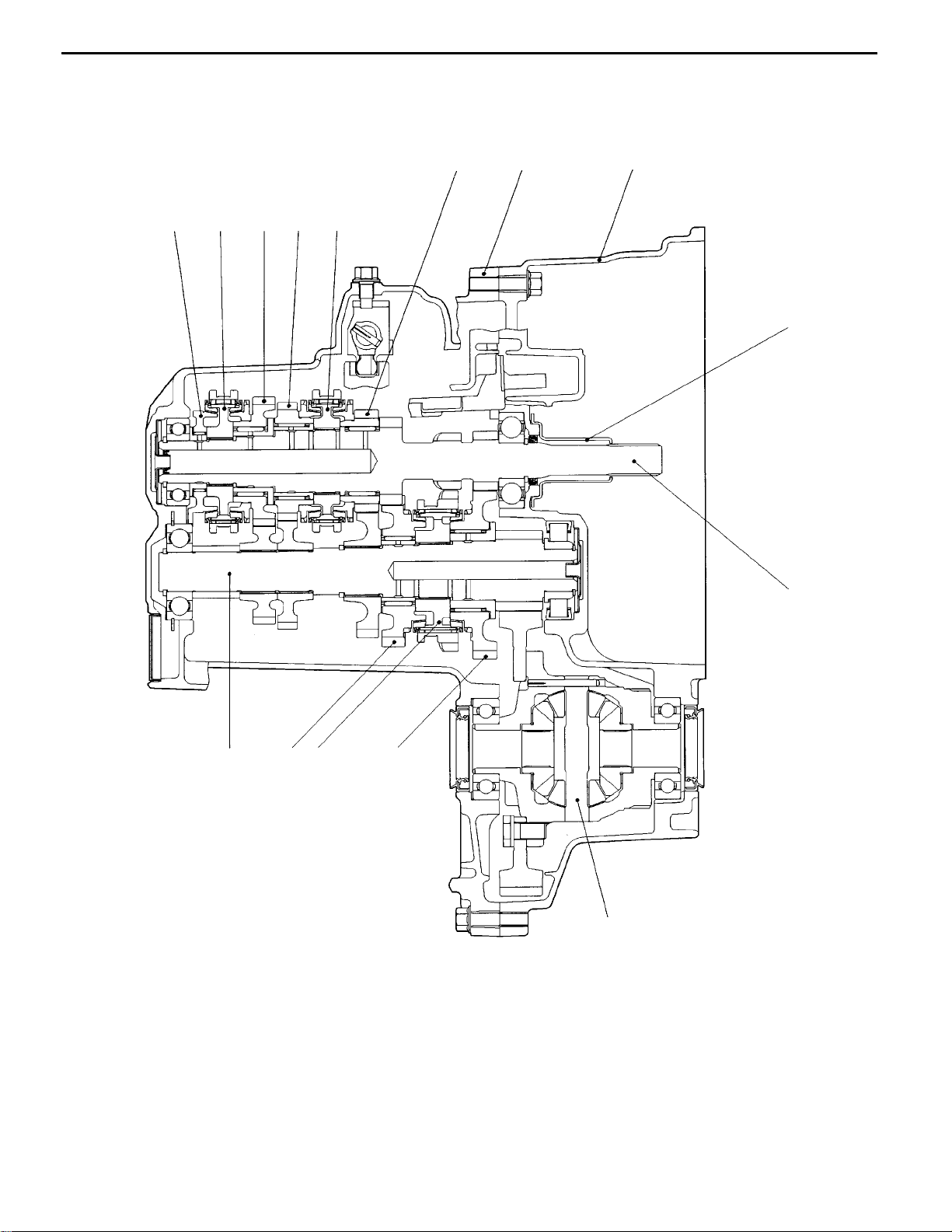
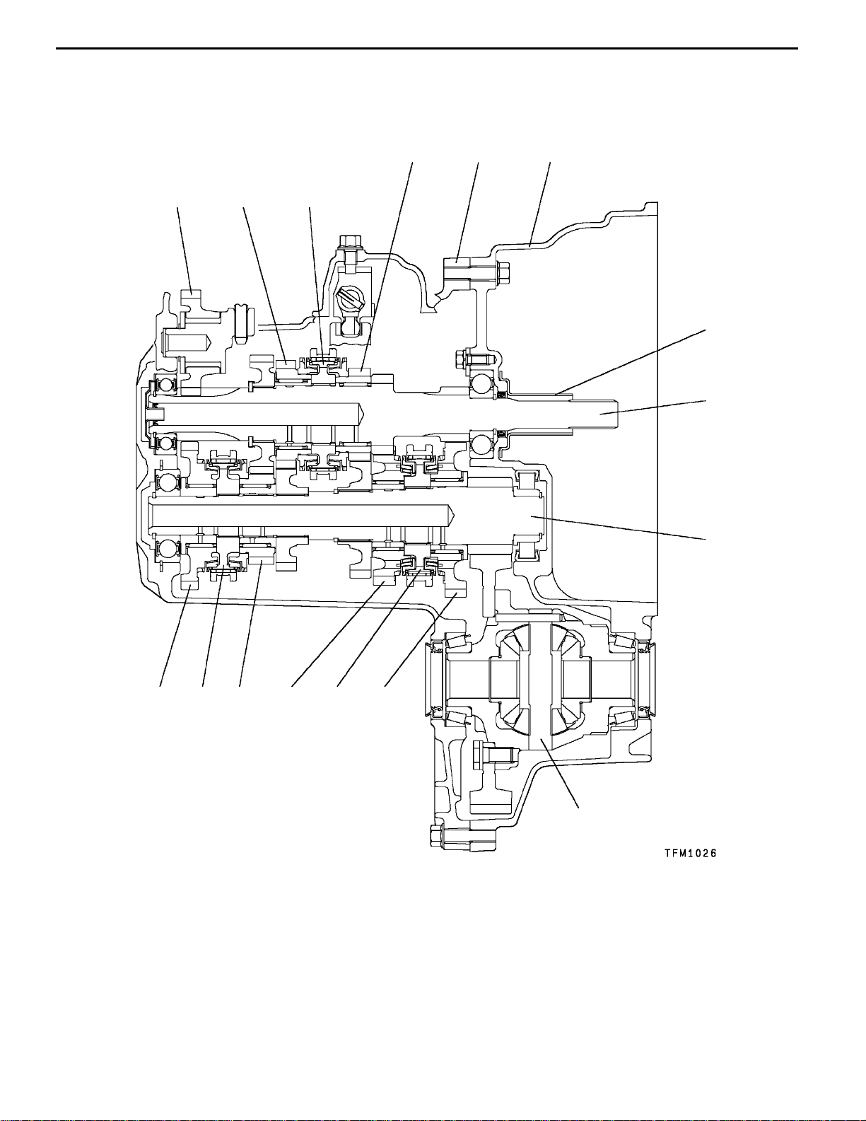
F5M41 <Types with single synchronizer ring for 2nd gear>
22B-0-3
67
2
1
3
5
4
8
9
10
15
1214 13
11
TFM0809
1. Reverse gear meshing noise prevention device
<Models with reverse brake>
2. 5th-reverse speed synchronizer hub
3. 5th speed gear
4. 4th speed gear
5. 3rd-4th speed synchronizer hub
6. 3rd speed gear
7. Transmission case
E
July 1999Mitsubishi Motors Corporation Revised
PWEE9508-F
8. Clutch housing
9. Release bearing retainer
10. Input shaft
11. Differential
12. 1st speed gear
13. 1st-2nd speed synchronizer hub
14. 2nd speed gear
15. Output shaft
Page 4
22B-0-4
MANUAL TRANSMISSION (E-W) -
General Information
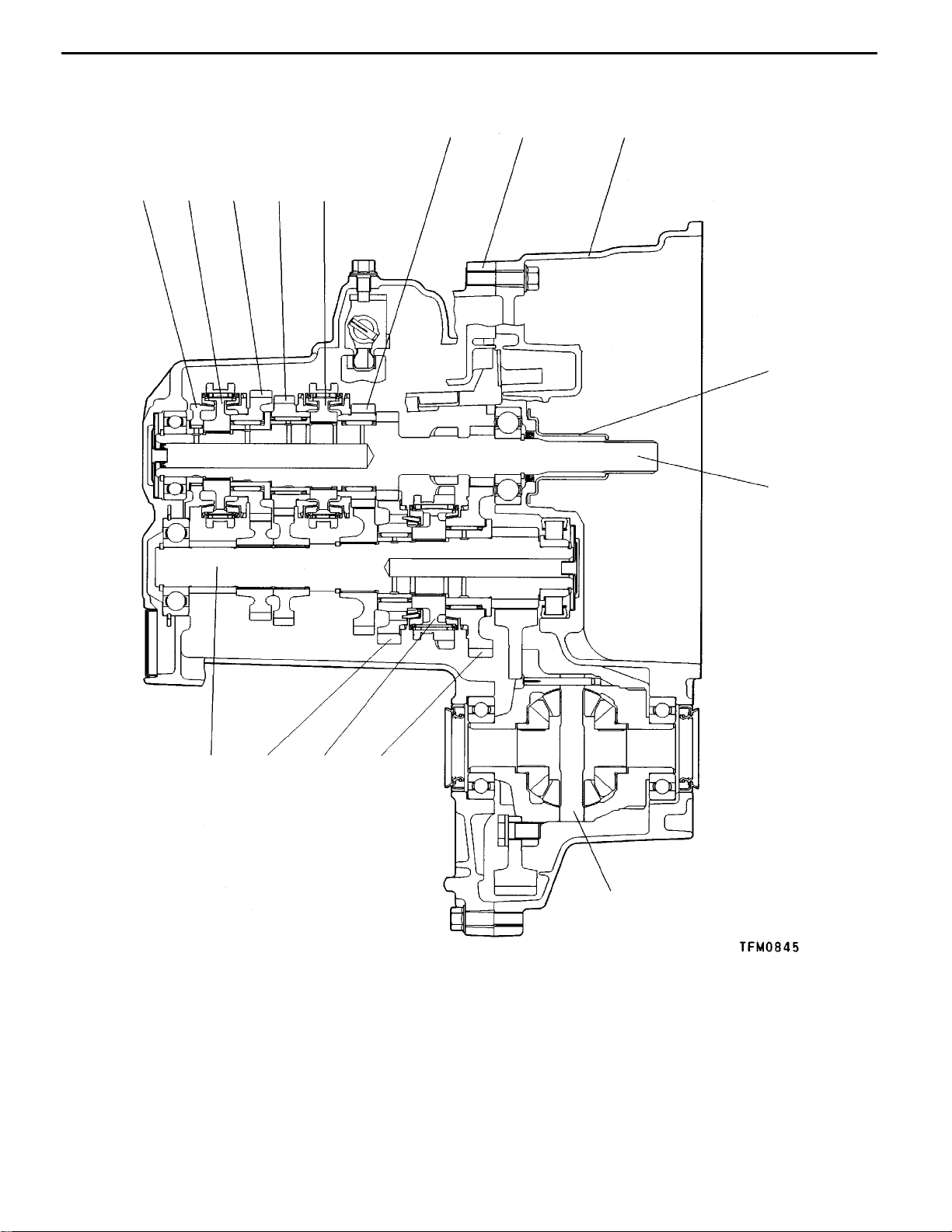
F5M41 <Types with double synchronizer ring for 2nd gear>
12
34
6
7
8
5
9
10
15
1214 13
11
1. Reverse gear meshing noise prevention device
2. 5th-reverse speed synchronizer hub
3. 5th speed gear
4. 4th speed gear
5. 3rd-4th speed synchronizer hub
6. 3rd speed gear
7. Transmission case
E
July 1999Mitsubishi Motors Corporation Revised
PWEE9508-F
8. Clutch housing
9. Release bearing retainer
10. Input shaft
11. Differential
12. 1st speed gear
13. 1st-2nd speed synchronizer hub
14. 2nd speed gear
15. Output shaft
Page 5
MANUAL TRANSMISSION (E–W) – General Information
22B-0-4a
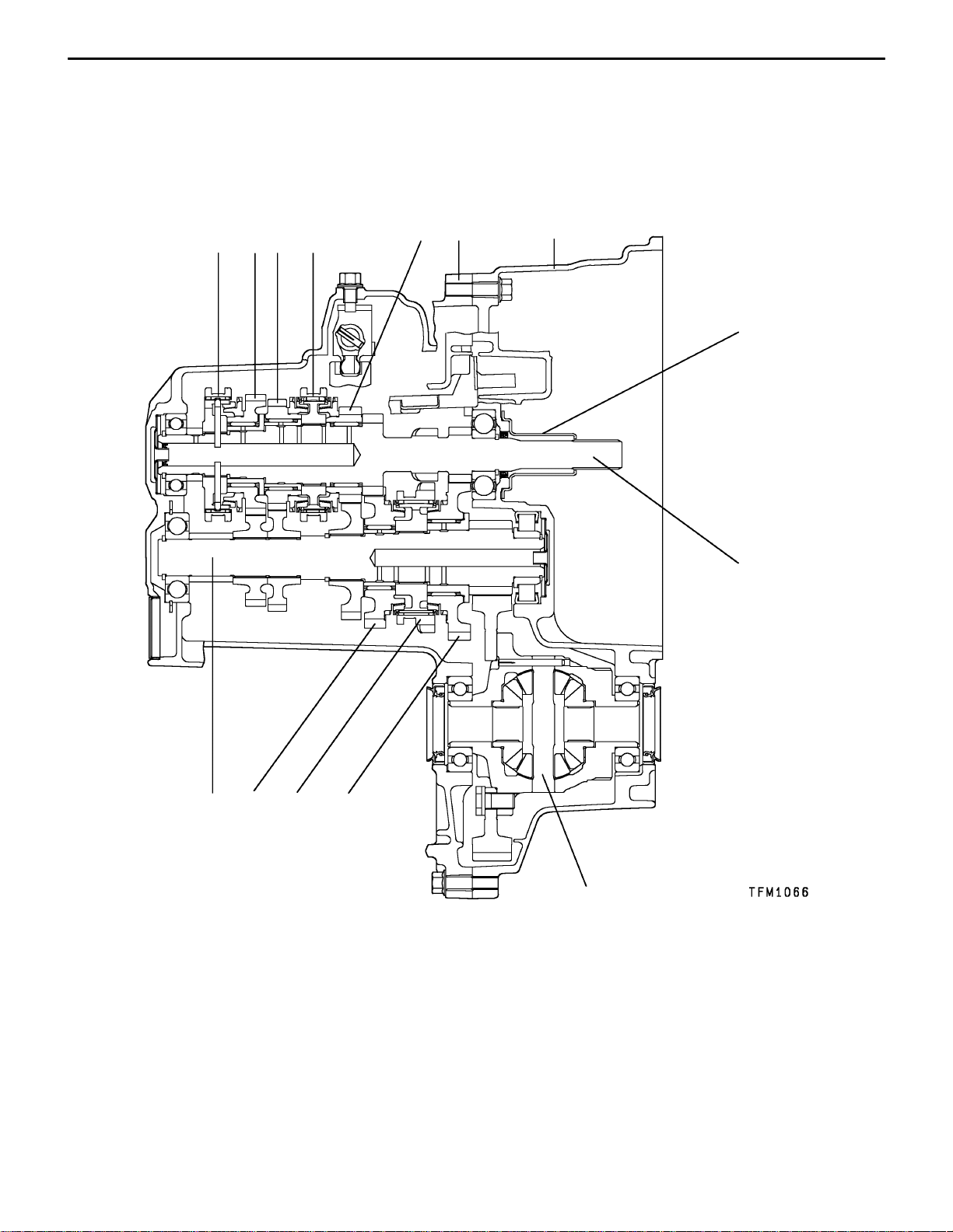
F5M41 <Types with single synchronizer ring for 2nd gear and synchronizer lever
for 5th gear>
1234
5
6
7
8
9
14
13
12
11
10
1. 5th-reverse speed synchronizer hub
2. 5th speed gear
3. 4th speed gear
4. 3rd-4th speed synchronizer hub
5. 3rd speed gear
6. Transmission case
7. Clutch housing
E
Dec. 2000Mitsubishi Motors Corporation Added
PWEE9508-H
8. Release bearing retainer
9. Input shaft
10. Differential
11. 1st speed gear
12. 1st-2nd speed synchronizer hub
13. 2nd speed gear
14. Output shaft
Page 6

22B-0-4b
MANUAL TRANSMISSION (E–W) – General Information
Intentionally blank
E
Dec. 2000Mitsubishi Motors Corporation Added
PWEE9508-H
Page 7
MANUAL TRANSMISSION (E-W) -
General Information
22B-0-5
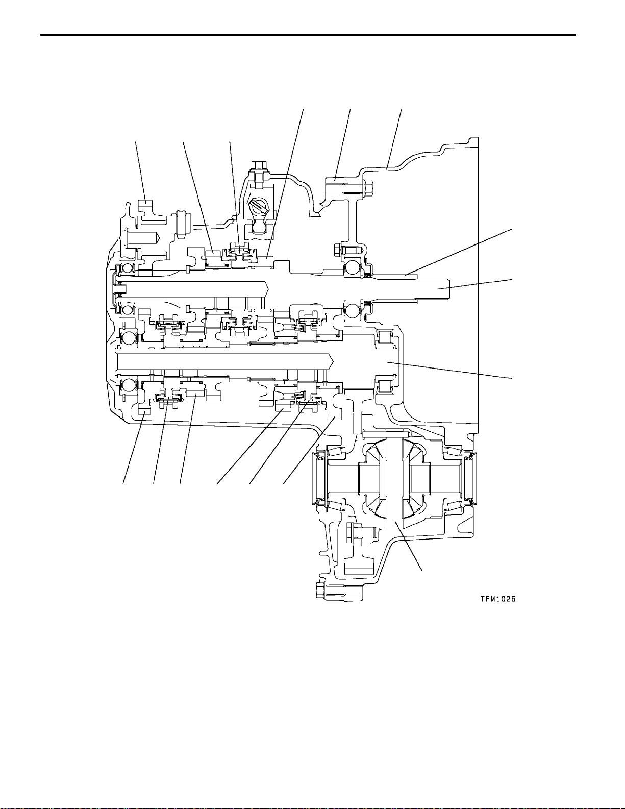
F5M42
<Types with single synchronizer ring for 1st gear and double synchronizer ring
for 2nd gear>
4
1
2
3
5
6
7
8
9
111214 131516
10
1. Reverse idler gear
2. 4th speed gear
3. 3rd-4th speed synchronizer hub
4. 3rd speed gear
5. Transmission case
6. Clutch housing
7. Release bearing retainer
8. Input shaft
E
July 1999Mitsubishi Motors Corporation Revised
PWEE9508-F
9. Output shaft
10. Differential
11. 1st speed gear
12. 1st-2nd speed synchronizer hub
13. 2nd speed gear
14. 5th speed gear
15. 5th-reverse speed synchronizer hub
16. Reverse gear
Page 8
22B-0-6
MANUAL TRANSMISSION (E-W) -
General Information
F5M42
<Types with double synchronizer ring for both 1st and 2nd gears, types with
double synchronizer ring for 1st gear and triple synchronizer ring for 2nd gear>
4
1
2
3
5
6
7
8
9
16
15
14
13
1112
10
1. Reverse idler gear
2. 4th speed gear
3. 3rd-4th speed synchronizer hub
4. 3rd speed gear
5. Transmission case
6. Clutch housing
7. Release bearing retainer
8. Input shaft
E
July 1999Mitsubishi Motors Corporation Revised
PWEE9508-F
9. Output shaft
10. Differential
11. 1st speed gear
12. 1st-2nd speed synchronizer hub
13. 2nd speed gear
14. 5th speed gear
15. 5th-reverse speed synchronizer hub
16. Reverse gear
Page 9
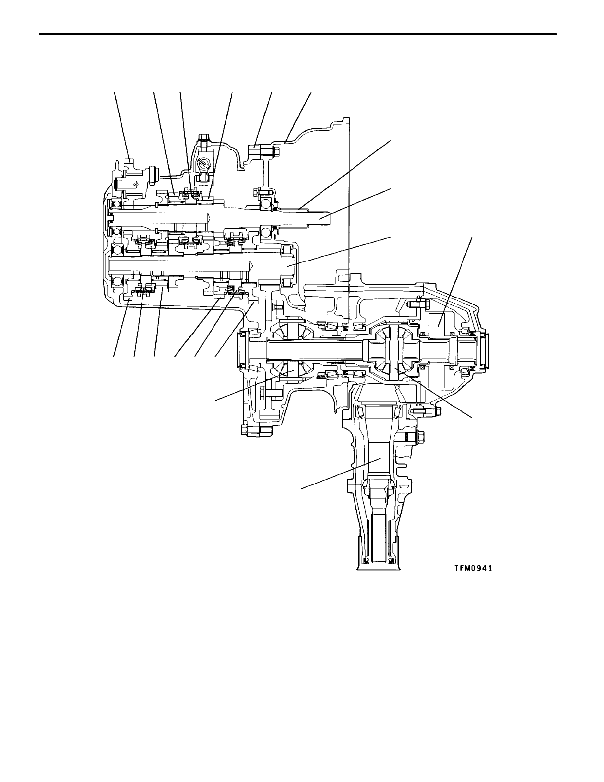
W5M42
MANUAL TRANSMISSION (E-W) -
General Information
22B-0-7
1
2
3
4
56
7
8
9
16
171819
15
14
10
13
1. Reverse idler gear
2. 4th speed gear
3. 3rd-4th speed synchronizer hub
4. 3rd speed gear
5. Transmission case
6. Clutch housing
7. Release bearing retainer
8. Input shaft
9. Output shaft
10. Viscous coupling
11
12
11. Front differential
12. Transfer driven gear
13. Center differential
14. 1st speed gear
15. 1st-2nd speed synchronizer hub
16. 2nd speed gear
17. 5th speed gear
18. 5th-reverse speed synchronizer hub
19. Reverse gear
E
Jun. 1998Mitsubishi Motors Corporation Added
PWEE9508-E
Page 10
MANUAL TRANSMISSION (E–W) – Specifications
1. SPECIFICATIONS
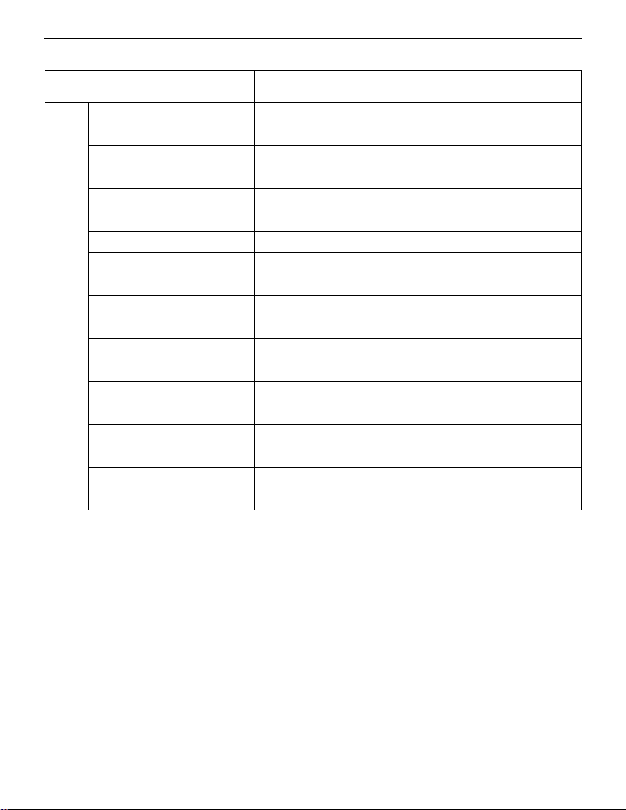
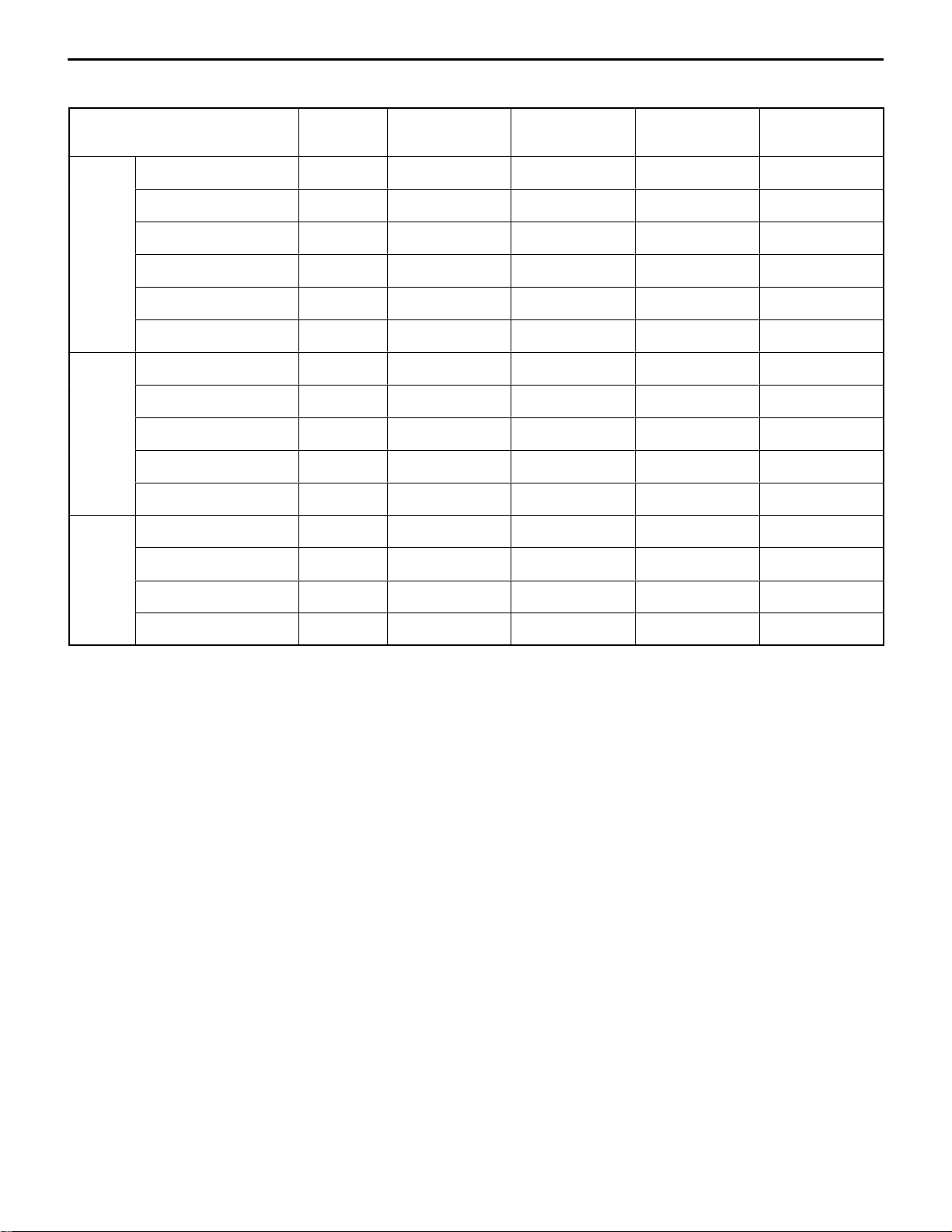
TRANSMISSION MODEL TABLE – MODEL 1996
22B-1-1
Transmission model Gear ratio Speedometer
gear ratio
EUR F5M41-1-B8A1 B 31/36 3.454 CJ4A 4G92-MVV
F5M41-1-F8A1 A 31/36 3.714 CJ4A, CK4A 4G92-MPI
F5M41-1-R8A A 31/36 4.052 CJ1A, CK1A 4G13
EXP F5M41-1-F8A1 A 31/36 3.714 CJ4A, CK4A 4G92-MPI
F5M41-1-R8A A 31/36 4.052 CJ1A, CK1A 4G13
F5M41-1-R8A A 31/36 4.052 CJ2A, CK2A 4G15
F5M42-1-Y8A C 31/36 4.625 CK4A 4G92-MIVEC
Final gear ratio Vehicle model Engine model
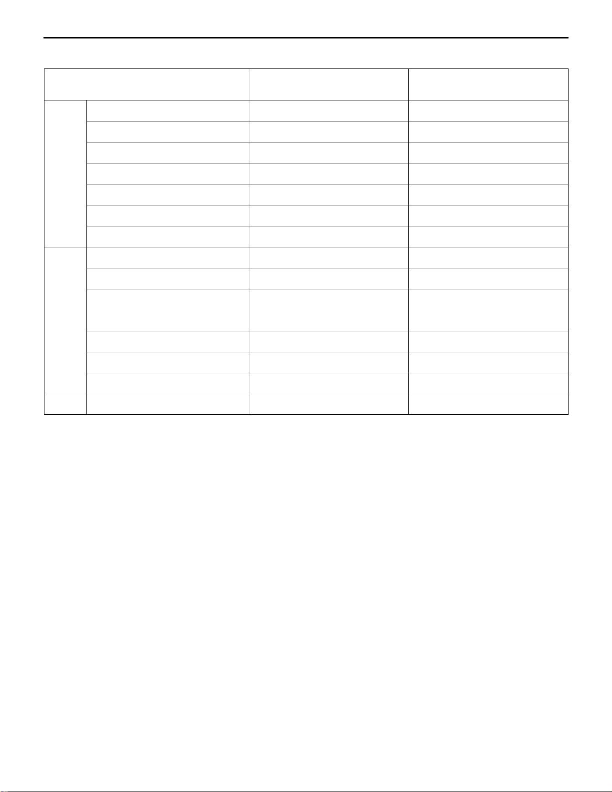
TRANSMISSION MODEL TABLE – MODEL 1997
Transmission model Gear ratio Speedometer
gear ratio
EUR F5M42-1-F7N D 30/36 3.722 EA2A, EA2W 4G63
F5M42-2-F6N2 F 29/36 3.722 EA5A, EA5W 6A13
F5M42-2-F6N5 E 29/36 3.722 EA6A, EA6W 4D68
Final gear ratio Vehicle model Engine model
EXP F5M42-1-F6N4 D 29/36 3.722 EA2A 4G63-MPI
F5M42-1-F7N D 30/36 3.722 EA2A 4G63-MPI
F5M42-1-R6N2 D 29/36 4.058 EA1A 4G93
F5M42-1-R6N3 D 29/36 4.058 EA2A 4G63-CARB
F5M42-2-F6N2 F 29/36 3.722 EA5A 6A13
F5M42-2-V6N D 29/36 4.312 EA4A 6A12
E
Dec. 2000Mitsubishi Motors Corporation Revised
PWEE9508-H
Page 11
22B-1-2
MANUAL TRANSMISSION (E–W) – Specifications
TRANSMISSION MODEL TABLE – MODEL 1998
Transmission model Gear ratio Speedometer
gear ratio
EUR F5M41-1-B8A2 B 31/36 3.454 CJ4A 4G92
F5M41-1-F8A5 A 31/36 3.714 CJ4A 4G92
F5M41-1-R8A1 A 31/36 4.052 CK1A, CJ1A 4G13
F5M42-2-F7N2 D 30/36 3.722 EA2A, EA2W 4G63
F5M42-1-F8A4 G 31/36 3.722 DA2A 4G93-GDI
F5M42-2-F6NA E 29/36 3.722 EA6A, EA6W 4D68
F5M42-2-F6N7 F 29/36 3.722 EA5A, EA5W 6A13
EXP F5M41-1-F8A5 A 31/36 3.714 CJ4A, CK4A 4G92
F5M41-1-R8A1 A 31/36 4.052 CJ1A, CK1A 4G13
F5M41-1-R8A1 A 31/36 4.052 CJ2A, CK2A 4G15
F5M42-1-R6N6 D 29/36 4.058 EA1A 4G93
F5M42-1–F6N9 D 29/36 3.722 EA2A 4G63
F5M42-2-R6N8 E 29/36 4.058 EA6A 4D68
Final gear ratio Vehicle model Engine model
E
Dec. 2000Mitsubishi Motors Corporation Revised
PWEE9508-H
Page 12
MANUAL TRANSMISSION (E–W) – Specifications
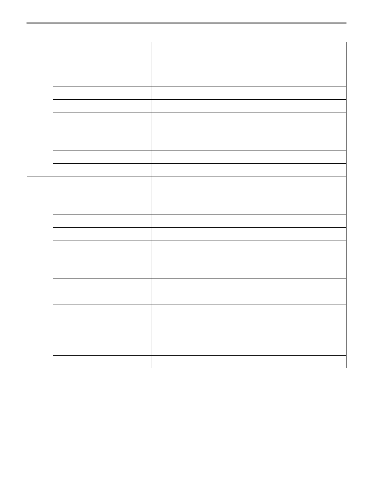
TRANSMISSION MODEL TABLE – MODEL 1999
22B-1-2a
Transmission model Gear ratio Speedometer
gear ratio
EUR F5M42-1-V5A4 D 28/36 4.312 N61W 4G93-GDI
F5M42-2-R5A3 G 28/36 4.058 N84W 4G64-GDI
W5M42-1-V5A1 H 28/36 4.352 N94W 4G64-GDI
F5M42-1-F8A4 G 31/36 3.722 DA2A 4G93-GDI
F5M42-2-F7N2 D 30/36 3.722 EA2A, EA2W 4G93
F5M42-2-F6NC G 29/36 3.722 EA3A, EA3W 4G64-GDI
F5M42-2-F6N7 F 29/36 3.722 EA5A, EA5W 6A13
F5M42-2-F6NA E 29/36 3.722 EA6A, EA6W 4D65
EXP F5M42-1-R6N6 D 29/36 4.058 EA1A 4G93
F5M42-1-R6N7 D 29/36 4.058 EA2A 4G63
F5M42-1-F6N9 D 29/36 3.722 EA2A 4G63
F5M42-1-F7N1 D 30/36 3.722 EA2A 4G63
F5M42-2-V6N1 D 29/36 4.312 EA4A 6A12-MIVEC
Final gear ratio Vehicle model Engine model
F5M42-2-F6N7 F 29/36 3.722 EA5A 6A13
F5M42-2-R6N8 E 29/36 4.058 EA6A 4D56
F5M42-2-R5A2 D 28/36 4.058 N84W 4G64
MMAL F5M41-1-F8A5 A 31/36 3.714 CJ2A, CK2A 4G15
F5M42-1-F8A7 F 31/36 3.722 CJ5A, CK5A 4G93
F5M42-2-R5A2 D 28/36 4.058 N84W 4G64
E
Dec. 2000Mitsubishi Motors Corporation Revised
PWEE9508-H
Page 13
22B-1-2b
MANUAL TRANSMISSION (E–W) – Specifications
TRANSMISSION MODEL TABLE – MODEL 2000
Transmission model Gear ratio Speedometer
gear ratio
EUR F5M41-1-R8A1 A 31/36 4.052 CJ1A 4G13
F5M41-1-F8A5 A 31/36 3.714 CJ4A 4G92
F5M41-1-B8A2 B 31/36 3.454 CJ4A 4G92-MVV
F5M42-1-R7A2 G 30/36 4.058 DA2A 4G93-GDI
F5M42-1-V5A4 D 28/36 4.312 N61W 4G93-GDI
F5M42-2-R5A3 G 28/36 4.058 N64W, N84W 4G64-GDI
W5M42-1-V5A1 H 28/36 4.352 N94W 4G64-GDI
EXP F5M41-1-R8A1 A 31/36 4.052 CJ1A, CK1A 4G13
F5M41-1-F8A5 A 31/36 3.714 CJ4A, CK4A 4G92
F5M42-1-R6N6 D 29/36 4.058 EA1A 4G93
F5M42-1-R6N7 D 29/36 4.058 EA2A 4G63
F5M42-1-F6N9 D 29/36 3.722 EA2A, EA2W 4G63
F5M42-2-F6N7 F 29/36 3.722 EA5A 6A13
Final gear ratio Vehicle model Engine model
F5M42-2-R5A2 D 28/36 4.058 N84W 4G64
MMAL F5M42-2-R5A2 D 28/36 4.058 N84W 4G64
E
Dec. 2000Mitsubishi Motors Corporation Revised
PWEE9508-H
Page 14
MANUAL TRANSMISSION (E–W) – Specifications
TRANSMISSION MODEL TABLE – MODEL 2001
22B-1-2c
Transmission model Gear ratio Speedometer
gear ratio
EUR F5M41-1-R8A1 A 31/36 4.052 CJ1A 4G13
F5M41-1-F8A5 A 31/36 3.714 CJ4A 4G92
F5M42-1-F8AC I 31/36 3.722 DG5A 4G93
F5M42-1-R7A2 G 30/36 4.058 DA2A 4G93
F5M42-2-F7N2 D 30/36 3.722 EA2A, W 4G63
F5M42-2-F6NC G 29/36 3.722 EA3A, W 4G64
F5M42-2-F6N7 F 29/36 3.722 EA5A, W 6A13
F5M42-2-V5A D 28/36 4.312 N63W 4G63
F5M42-2-R5A3 G 28/36 4.058 N64W 4G64
EXP F5M41-1-R8A1 A 31/36 4.052 CJ1A, CJ2A 4G13, 4G15
F5M41-1-R7B A 30/36 4.052 CS1A, CS3A 4G13, 4G18
F5M41-1-R8B A 31/36 4.052 CS1A, CS3A 4G13, 4G18
F5M41-1-F8A5 A 31/36 3.714 CJ4A 4G92
Final gear ratio Vehicle model Engine model
F5M42-1-F6N9 D 29/36 3.722 EA2W 4G63
F5M42-1-F7N1 D 30/36 3.722 EA2W 4G63
F5M42-1-R6N6 D 29/36 4.058 EA1A 4G93
F5M42-2-R6N7 D 29/36 4.058 EA2A 4G63
F5M42-1-F6N9 D 29/36 3.722 EA2A 4G63
F5M42-2-F6N7 F 29/36 3.722 EA5A 6A13
F5M42-2-R6N8 E 29/36 4.058 EA6A 4D68
F5M42-2-R5A2 D 28/36 4.058 N84W 4G64
MMAL F5M41-1-F8A5 A 31/36 3.714 CJ2A, CK2A 4G15
F5M42-1-F8A7 F 31/36 3.722 CJ5A, CK5A 4G93
F5M42-2-R5A2 D 28/36 4.058 N84W 4G64
E
Dec. 2000Mitsubishi Motors Corporation Revised
PWEE9508-H
Page 15
22B-1-2d
MANUAL TRANSMISSION (E–W) – Specifications
TRANSMISSION MODEL TABLE – MODEL 2002
Transmission model Gear ratio Speedometer
gear ratio
EUR F5M41-1-R8A1 A 31/36 4.052 CJ1A 4G13
F5M41-1-F8A5 A 31/36 3.714 CJ4A 4G92
F5M41-1-R8B A 31/36 4.052 CS3A 4G18
F5M42-1-F8AC I 31/36 3.722 DG5A 4G93
F5M42-1-R7A2 G 30/36 4.058 DA2A 4G93
F5M42-2-V5A D 28/36 4.312 N83W 4G63
F5M42-2-R5A3 G 28/36 4.058 N84W 4G64
W5M42-1-V5A1 H 28/36 4.352 N94W 4G64
EXP F5M41-1-F8A5 A 31/36 3.714 CJ4A 4G92
F5M41-1-R8A1 A 31/36 4.052 CJ1A, CJ2A 4G13, 4G15
F5M42-2-F6N7 F 29/36 3.722 EA5A 6A13
F5M42-1-R6N6 D 29/36 4.058 EA1A 4G93
F5M42-1-R6N7 D 29/36 4.058 EA2A 4G63
Final gear ratio Vehicle model Engine model
F5M42-1-F6N9 D 29/36 3.722 EA2A, W 4G63
F5M42-2-R6N8 E 29/36 4.058 EA6A 4D68
F5M41-1-R7B A 30/36 4.052 CS1A, CS3A 4G13, 4G18
F5M41-1-R8B A 31/36 4.052 CS1A, CS3A 4G13, 4G18
F5M41-1-V7B A 30/36 4.333 CS1A 4G13
F5M41-1-V8B1 A 31/36 4.333 CS1A 4G13
F5M42-1-R7A2 G 30/36 4.058 DA3A 4G93
F5M42-2-R5A2 D 28/36 4.058 N84W 4G64
MMAL F5M42-2-R5A2 D 28/36 4.058 N84W 4G64
F5M41-1-F8A5 A 31/36 3.714 CJ2A 4G15
F4M42-1-F8A7 F 31/36 3.722 CJ5A, CK5A 4G93
E
Mar . 2002Mitsubishi Motors Corporation Revised
PWEE9508-I
Page 16
MANUAL TRANSMISSION (E–W) – Specifications
TRANSMISSION MODEL TABLE – MODEL 2003
22B-1-2e
Transmission model Gear ratio Speedometer
gear ratio
EUR F5M41-1-F8A5 A 31/36 3.714 CJ4A 4G92
F5M41-1-R8A1 A 31/36 4.052 CJ1A 4G13
F5M42-2-V5A D 28/36 4.312 N83W 4G64
F5M42-2-R5A3 G 28/36 4.058 N84W 4G64
W5M42-1-V5A1 H 28/36 4.325 N94W 4G64
F5M42-1-R7A2 G 30/36 4.058 DA2A 4G93
EXP F5M41-1-F8A5 A 31/36 3.714 CJ4A 4G92
F5M41-1-R8A1 A 31/36 4.052 CJ1A, CJ2A 4G13, 4G15
F5M42-2-R5A2 D 28/36 4.058 N84W 4G64
F5M41-1-R7B1 A 30/36 4.052 CS1A, CS3A 4G13, 4G18
F5M41-1-R8B1 A 31/36 4.052 CS1A, CS3A 4G13, 4G18
MMAL F5M41-1-F8A5 A 31/36 3.714 CJ2A 4G15
F5M42-1-F8A7 F 31/36 3.722 CJ5A, CK5A 4G93
Final gear ratio Vehicle model Engine model
F5M42-2-R5A2 D 28/36 4.058 N84W 4G64
F5M42-1-F8B2 F 31/36 3.722 CS6A 4G93
E
Mar . 2002Mitsubishi Motors Corporation Revised
PWEE9508-I
Page 17

22B-1-2f
MANUAL TRANSMISSION (E–W) – Specifications
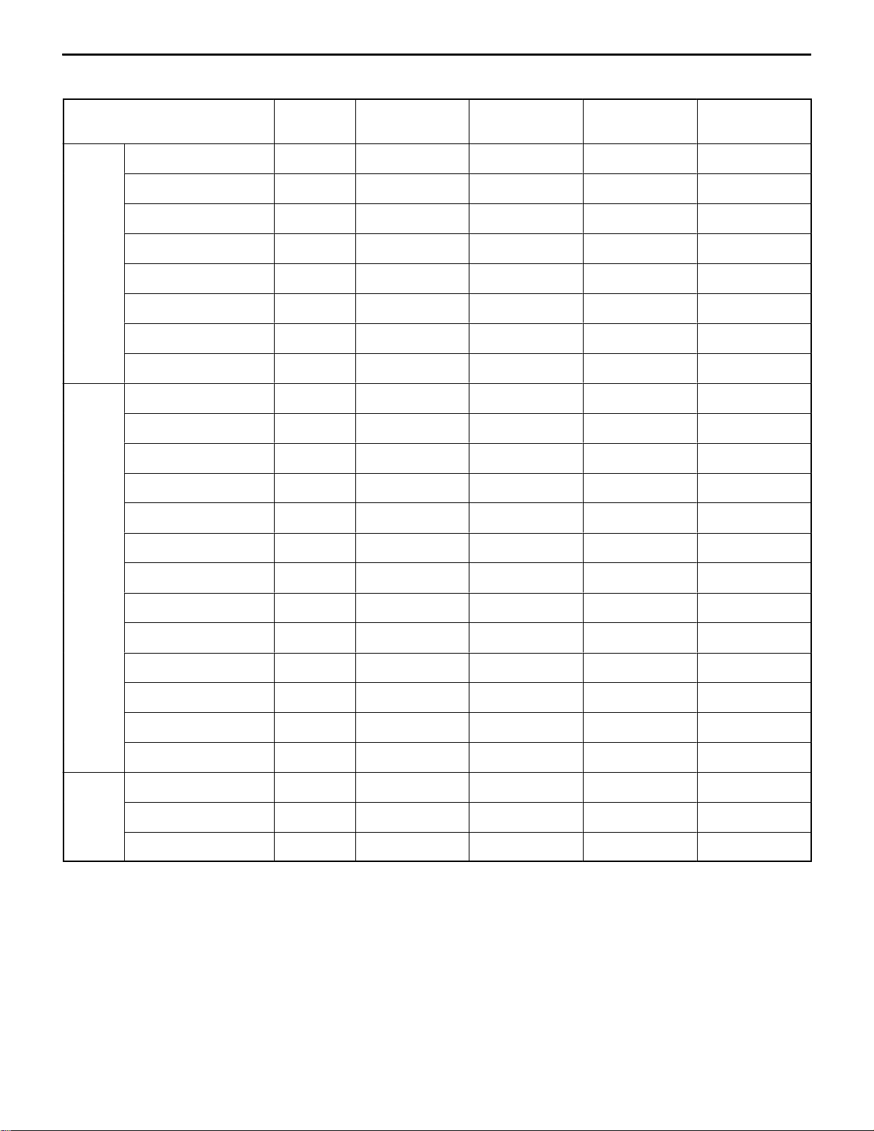
GEAR RATIO TABLE
A B C D E F G
1st 3.583 3.727 3.071 3.583 3.583 3.583 3.583
2nd 1.947 1.947 1.947 1.947 1.947 1.947 1.947
3rd 1.343 1.343 1.379 1.379 1.379 1.379 1.266
4th 0.976 0.976 1.030 1.030 1.030 1.030 0.970
5th 0.804 0.804 0.767 0.820 0.733 0.767 0.767
Reverse 3.416 3.416 3.363 3.363 3.363 3.363 3.363
H I
1st 3.583 3.583
2nd 1.947 1.947
3rd 1.266 1.266
4th 0.970 0.970
5th 0.767 0.820
Reverse 3.363 3.363
Transfer 0.3018 –
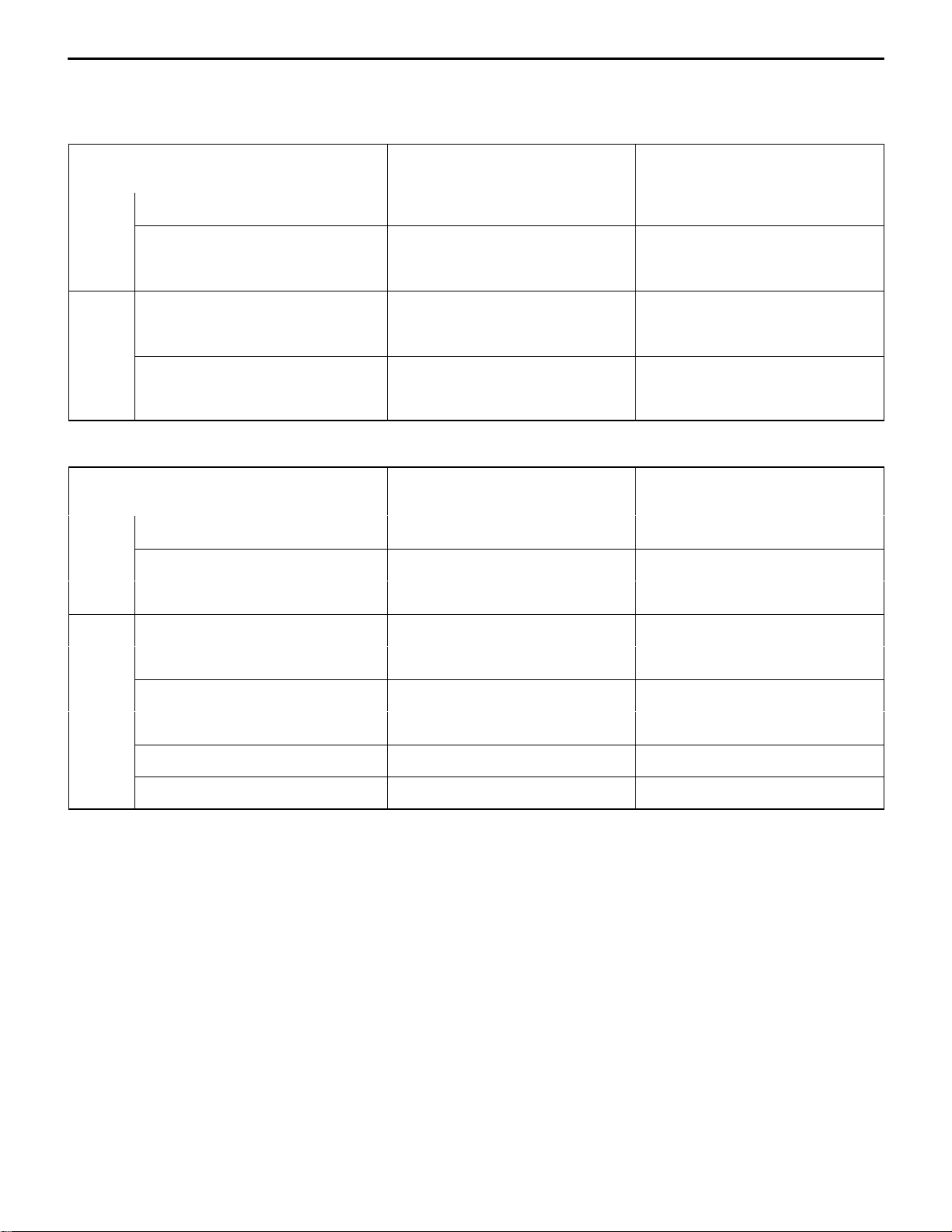
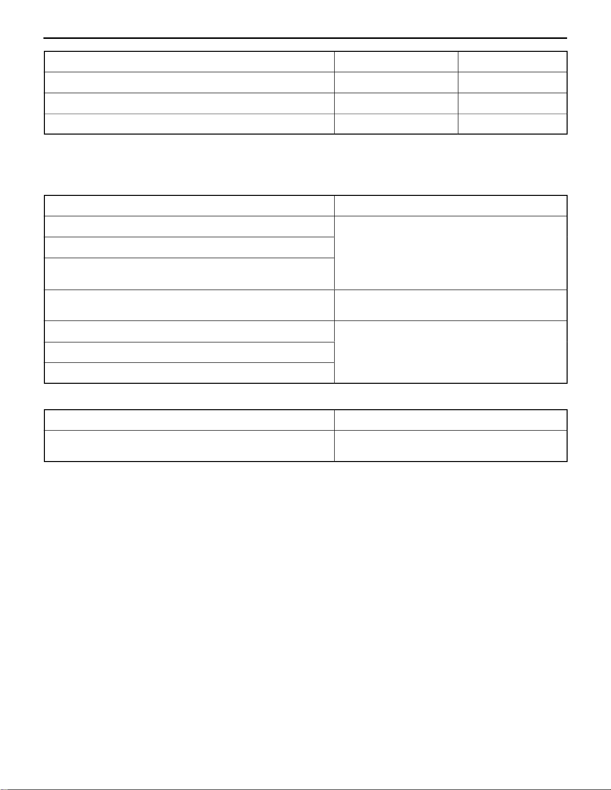
SERVICE SPECIFICATIONS
Items Allowable range Limit
Input shaft front bearing end play mm –0.01–0.12 –
Input shaft rear bearing end play <F5M41> mm –0.01–0.09 –
Input shaft rear bearing end play <F5M42, W5M42> mm –0.01–0.12 –
Input shaft 5th speed gear end play <F5M42, W5M42> mm –0.01–0.09 –
Output shaft front bearing end play mm –0.01–0.12 –
Output shaft rear bearing end play mm –0.01–0.09 –
Output shaft 3rd speed gear end play mm –0.01–0.09 –
Differential case end play <F5M41> mm 0.05–0.17 –
Differential case pinion backlash <F5M41, F5M42> mm 0–0.150 –
Differential case preload <F5M42> mm 0.05–0.11 –
NOTE: Standard play = 0 mm
E
Mar . 2002Mitsubishi Motors Corporation Revised
PWEE9508-I
Page 18
MANUAL TRANSMISSION (E–W) – Specifications
t
Items Allowable range Limit
Center differential case pinion backlash <W5M42> mm 0.025–0.150 –
Center differential case preload <W5M42> mm 0.05–0.11 –
Synchronizer ring back surface to gear clearance mm – 0.5
22B-1-2g
NOTE: Standard play = 0 mm
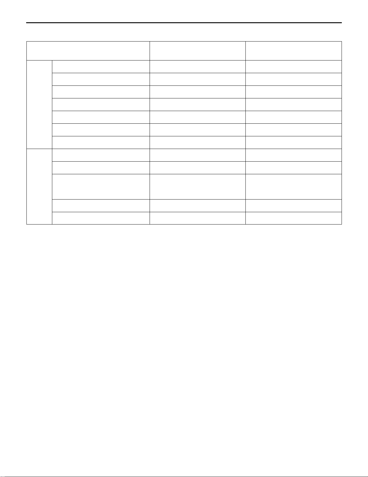
SEALANTS AND ADHESIVES
TRANSMISSION
Items Specified sealants and adhesives
Clutch housing–transmission case mating surface MITSUBISHI genuine sealant part No. MD997740
or equivalen
Control housing–transmission case mating surface
Under cover–transmission case mating surface
<F5M42, W5M42>
Air breather 3M SUPER WEATHERSTRIP No. 8001 or
equivalent
Differential drive gear bolt <F5M41, F5M42> 3M STUD Locking No. 4170 or equivalent
Center differential drive gear bolt <W5M42>
Front bearing retainer bolt (countersink head bolt) <F5M41>
TRANSFER
Item Specified sealant
Air breather 3M SUPER WEATHERSTRIP No. 8001 or
equivalent
E
Mar . 2002Mitsubishi Motors Corporation Added
PWEE9508-I
Page 19

22B-1-2h
MANUAL TRANSMISSION (E–W) – Specifications
Intentionally blank
E
Mar . 2002Mitsubishi Motors Corporation Added
PWEE9508-I
Page 20
MANUAL TRANSMISSION (E-W) -
Specifications
22B-1-3
FORM-IN-PLACE GASKET
The transmission has several areas where the form-in-place gasket (FIPG) is in use. To ensure that the
gasket fully serves its purpose, it is necessary to observe some precautions when applying the gasket.
Bead size, continuity and location are of paramount importance. Too thin a bead could cause leaks. Too
thick a bead, on the other hand, could be squeezed out of location, causing blocking or narrowing of
the fluid feed line. To eliminate the possibility of leaks from a joint, therefore, it is absolutely necessary
to apply the gasket evenly without a break, while observing the correct bead size.
Since the RTV hardens as it reacts with the moisture in the atmospheric air, it is normally used in the
metallic flange areas.
DISASSEMBLY
The parts assembled with the FIPG can be easily disassembled without use of a special method. In some
cases, however, the sealant between the joined surfaces may have to be broken by lightly striking with
a mallet or similar tool. A flat and thin gasket scraper may be lightly hammered in between the joined
surfaces. In this case, however, care must be taken to prevent damage to the joined surfaces.
Surface Preparation
Thoroughly remove all substances deposited on the gasket application surfaces, using a gasket scraper
or wire brush. Check to ensure that the surfaces to which the FIPG is to be applied is flat. Make sure
that there are no oils, greases and foreign substances deposited on the application surfaces. Do not forget
to remove the old sealant remaining in the bolt holes.
FORM-IN-PLACE GASKET APPLICATION
When assembling parts with the FIPG, you must observe some precautions, but the procedures is very
simple as in the case of a conventional precut gasket.
Applied FIPG bead should be of the specified size and without breaks. Also be sure to encircle the bolt
hole circumference with a completely continuous bead. The FIPG can be wiped away unless it is hardened.
While the FIPG is still moist (in less than 15 minutes), mount the parts in position. When the parts are
mounted, make sure that the gasket is applied to the required area only. In addition, do not apply any
oil or water to the sealing locations or start the engine until a sufficient amount of time (about one hour)
has passed after installation is completed.
The FIPG application procedure may vary on different areas. Observe the procedure described in the
text when applying the FIPG.
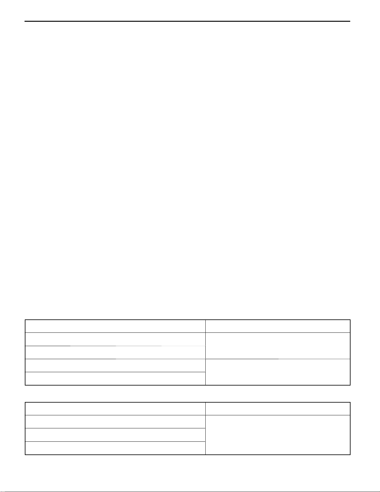
LUBRICANTS
TRANSMISSION
Items Specified lubricants
Drive shaft oil seal lip area Hypoid gear oil SAE 75W-85W conforming to API
classification GL-4 or higher
Control shaft oil seal lip area
Input shaft oil seal lip area MITSUBISHI genuine grease part No. 0101011 or
equivalent
Select lever shoe
TRANSFER
Items Specified lubricants
Drive shaft oil seal lip area Hypoid gear oil SAE 75W-85W conforming to API
classification GL-4 or higher
Front differential oil seal lip area
Each O-ring
E
Jun. 1998Mitsubishi Motors Corporation Revised
PWEE9508-E
Page 21
22B-1-4
(For adjustment o input sha t ront bearing end
(For adjustment o input sha t rear bearing end
(For adjustment of output shaft rear bearing end
(For adjustment o input sha t 5th speed gear
(For adjustment o output sha t ront bearing end
(For adjustment o input sha t rear bearing end
MANUAL TRANSMISSION (E–W) – Specifications
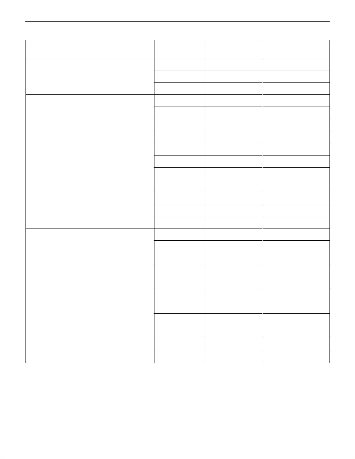
SNAP RINGS, SPACERS AND THRUST PLATE ADJUSTMENT
Part name Thickness mm Identification
symbol
Snap ring
f
play)
Snap ring
f
play ....F5M41)
f
play ....F5M42, W5M42)
f
f
f
f
2.24 None MD706537
2.31 Blue MD706538
2.38 Brown MD706539
2.31 Black (2) MD747149
2.35 None MD746561
2.39 Blue MD746562
2.43 Brown MD746563
2.47 Green MD746564
2.51 White MD746565
2.55 Yellow MD746566
2.59 Black MD746567
2.63 Orange MD746568
2.67 Blue MD746569
Part No.
2.71 Brown MD746570
Thrust plate: F5M42, W5M42
f
end play)
Snap ring
f
play)
f
play ....F5M42, W5M42) 1.59 Yellow (2) MD746710
f
f
f
f
2.82 0 MD748015
2.86 2 MD748016
2.90 3 MD748017
2.94 5 MD748018
2.98 6 MD748019
3.02 7 MD748020
3.06 8 MD748021
3.10 9 MD748022
1.43 Green (2) MD746708
1.51 White (2) MD746709
E
Dec. 2000Mitsubishi Motors Corporation Revised
PWEE9508-H
Page 22
MANUAL TRANSMISSION (E-W) -
Specifications
22B-1-5
Part name Part No.Identification
Snap ring: F5M41 2.31 Black (2) MD748800
(For adjustment of output shaft rear bearing end
play)
Snap ring: F5M41 2.81 Green MD748782
(For adjustment of output shaft 3rd speed gear
end play)
Thickness mm
symbol
2.35 None MD748801
2.39 Blue MD748802
2.43 Brown MD748803
2.47 Green MD748804
2.51 White MD748805
2.55 Yellow MD748806
2.59 Black MD748807
2.63 Orange MD748808
2.67 Blue MD748809
2.71 Brown MD748810
2.85 White MD748783
2.89 Yellow MD748784
2.93 Black MD748785
2.97 Orange MD748786
3.01 Red MD748787
3.05 Pink MD748788
3.09 Blue MD748789
Snap ring: F5M42, W5M42 2.81 Green MD745799
(For adjustment of output shaft 3rd speed gear
end play)
2.85 White MD745800
2.89 Yellow MD745801
2.93 Black MD745802
2.97 Orange MD745803
3.01 Red MD745804
3.05 Pink MD745805
3.09 Blue MD745806
E
July 1999Mitsubishi Motors Corporation Revised
PWEE9508-F
Page 23
22B-1-6
MANUAL TRANSMISSION (E-W) -
Specifications
Part name Part No.Identification
Spacer: F5M41 0.77 77 MD754476
(For adjustment of differential case end play)
Thickness mm
symbol
0.86 86 MD720938
0.95 95 MD720941
1.04 04 MD720944
1.13 D MD700270
1.22 G MD700271
1.31 E MD706574
1.40 None MD706573
1.49 C MD706572
1.58 B MD706571
1.67 A MD706570
1.76 F MD706575
E
July 1999Mitsubishi Motors Corporation Revised
PWEE9508-F
Page 24
MANUAL TRANSMISSION (E–W) – Specifications
(For adjustment o di erential case preload)
22B-1-7
Part name Thickness mm Identification
symbol
Spacer: F5M42
f
ff
0.71 71 MD754475
0.74 74 MD727660
0.77 77 MD754476
0.80 80 MD727661
0.83 83 MD720937
0.86 86 MD720938
0.89 89 MD720939
0.92 92 MD720940
0.95 95 MD720941
0.98 98 MD720942
1.01 01 MD720943
1.04 04 MD720944
1.07 07 MD720945
Part No.
1.10 J MD710454
1.13 D MD700270
1.16 K MD710455
1.19 L MD710456
1.22 G MD700271
1.25 M MD710457
E
Dec. 2000Mitsubishi Motors Corporation Revised
PWEE9508-H
Page 25
22B-1-8
(For adjustment o center di erential case
(For adjustment o di erential case backlash)
(For adjustment o center di erential case pinion
MANUAL TRANSMISSION (E–W) – Specifications
Part name Part No.Identification
Spacer: W5M42
f
preload)
ff
Thickness mm
symbol
0.74 74 MD727660
0.77 77 MD745476
0.80 80 MD727661
0.83 83 MD720937
0.86 86 MD720938
0.89 89 MD720939
0.92 92 MD720940
0.95 95 MD720941
0.98 98 MD720942
1.01 01 MD720943
1.04 04 MD720944
1.07 07 MD720945
1.10 J MD710454
Spacer: F5M41, F5M42
f
ff
1.13 D MD700270
1.16 K MD710455
1.19 L MD710456
1.22 G MD700271
1.25 M MD710457
1.28 N MD710458
1.31 E MD706574
0.72 – 0.79 – MA180862
0.85 – 0.90 – MA180861
0.94 – 0.98 – MA180860
1.02 – 1.06 – MA180875
1.06 – 1.10 – MR581570
1.12 – 1.16 – MA180876
1.16 – 1.20 – MR581571
Spacer: W5M42
f
backlash)
E
ff
Dec. 2000Mitsubishi Motors Corporation Revised
0.48 – 0.55 – MD744236
0.56 – 0.65 – MD744235
0.66 – 0.73 – MD744234
0.74 – 0.81 – MD744233
0.82 – 0.89 – MD744232
PWEE9508-H
Page 26
MANUAL TRANSMISSION (E–W) – Specifications
TORQUE SPECIFICATIONS
TRANSMISSION
Items Nm
Under cover mounting bolt <F5M42, W5M42> 6.9
Interlock plate bolt 30
Clutch housing–transmission case mounting bolt 44
Clutch release bearing retainer mounting bolt 9.8
Control housing mounting bolt 18
Shift cable bracket mounting bolt 18
Speedometer gear mounting bolt 3.9
Stopper bracket mounting bolt 19
Select lever mounting bolt 18
Select lever mounting nut 11
22B-1-9
Center differential flange mounting screw <W5M42> 3.9
Center differential drive gear mounting bolt <W5M42> 132
Differential drive gear mounting bolt <F5M41, F5M42> 132
Back-up lamp switch 32
Front bearing retainer mounting bolt 18
Poppet spring 32
Restrict ball <F5M41> 32
Reverse idler gear shaft mounting bolt 48
Reverse shift lever mounting bolt <F5M41> 18
Roll stopper bracket mounting bolt 70
Oil temperature sensor <For GDI engine only> 22
Connector bracket mounting bolt <For GDI engine except DA2A> 18
Clutch fluid line bracket mounting bolt <DA2A only> 18
TRANSFER
Items Nm
Transfer cover mounting bolt 23
Transmission – transfer mounting bolt 69
E
Dec. 2000Mitsubishi Motors Corporation Revised
PWEE9508-H
Page 27
MANUAL TRANSMISSION (E-W) -
2. SPECIAL TOOLS
TRANSMISSION
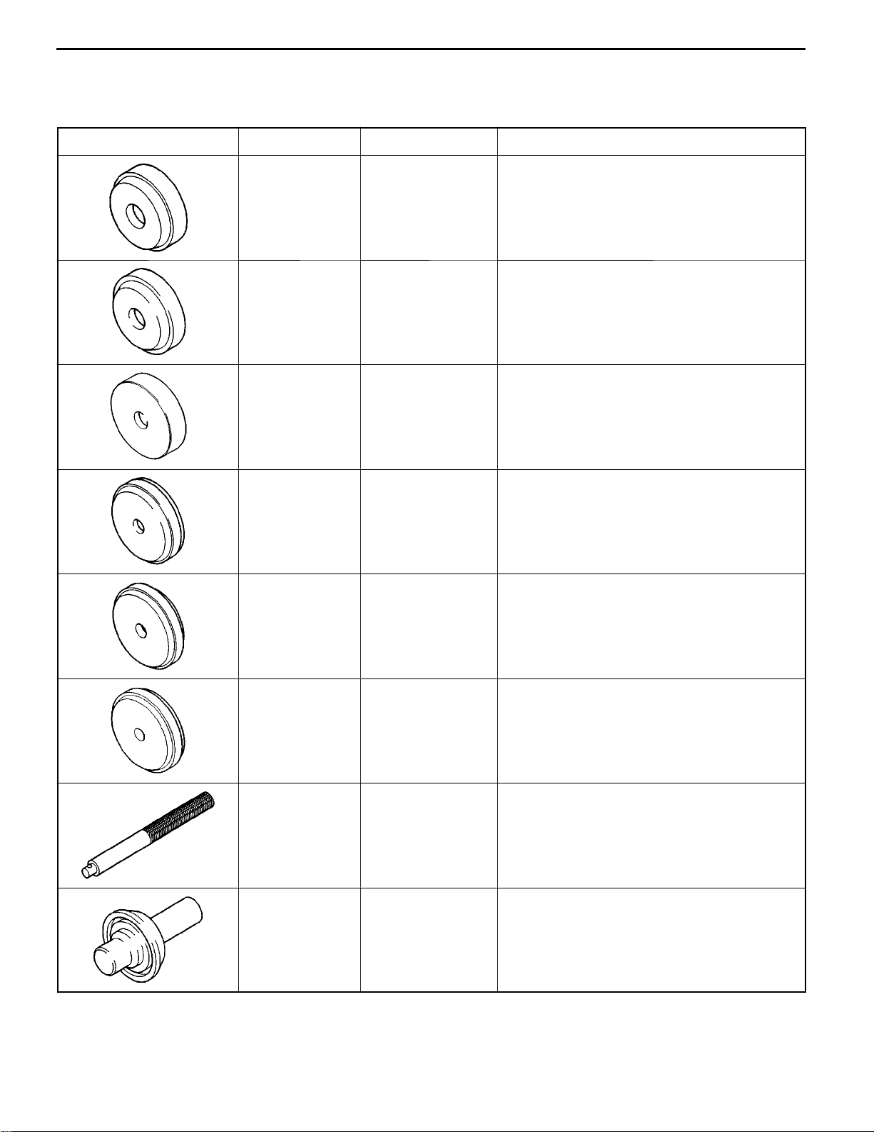
Tool Number Name Use
MB990926 Installer adapter Installation of clutch housing input shaft oil seal
MB990927 Installer adapter Installation of sealing cap
MB990930 Installer adapter Removal of center differential taper roller
Special Tools
bearing <W5M42>
22B-2-1
MB990934 Installer adapter Installation of roller bearing outer race
MB990935 Installer adapter Installation of differential case taper roller
bearing outer race
MB990937 Installer adapter Installation of center differential taper roller
bearing <W5M42>
MB990938 Handle Use with Installer adapter
MD998325 Differential oil seal
installer
E
Jun. 1998Mitsubishi Motors Corporation Revised
PWEE9508-E
Installation of differential oil seal
<F5M41, F5M42>
Page 28
22B-2-2
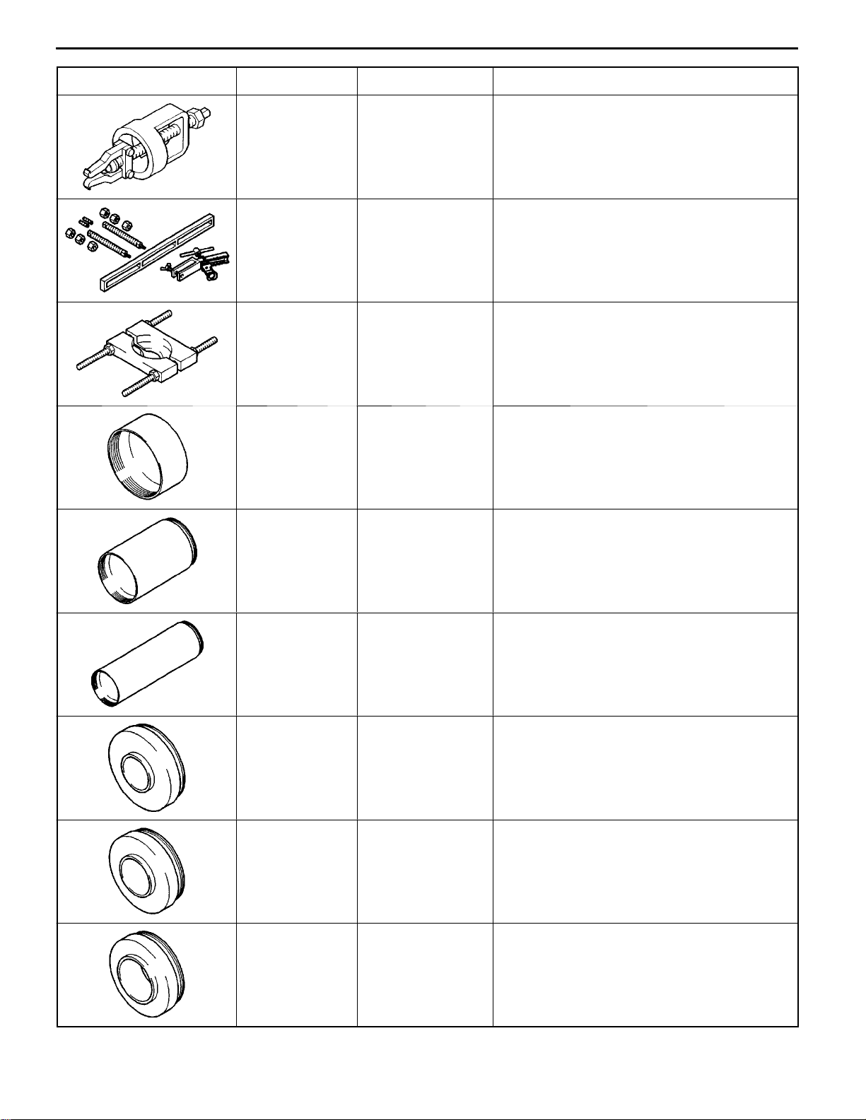
Tool UseNameNumber
MANUAL TRANSMISSION (E-W) -
Special Tools
MD998346 Bearing outer race
remover
MD998772 Valve spring com-
pressor
MD998801 Bearing remover Installation and removal of gears, bearings and
MD998812 Installer cap Use with Installer and Installer adapter
Removal of roller bearing outer race
Removal of roller bearing outer race
sleeves
MD998813 Installer-100 Use with Installer cap and Installer adapter
MD998814 Installer-200 Use with Installer cap and Installer adapter
MD998816 Installer adapter
(30)
MD998817 Installer adapter
(34)
Installation of input shaft front bearing
<F5M42, W5M42>
Installation of input shaft front bearing
<F5M41>, output shaft rear bearing <F5M42,
W5M42>
MD998818 Installer adapter
(38)
E
Jun. 1998Mitsubishi Motors Corporation Revised
PWEE9508-E
Installation of input shaft rear bearing, roller
bearing inner race, reverse gear, needle roller
bearing, reverse gear bearing sleeve <F5M42,
W5M42> and reverse bearing sleeve
<F5M41>
Page 29
MANUAL TRANSMISSION (E-W) -
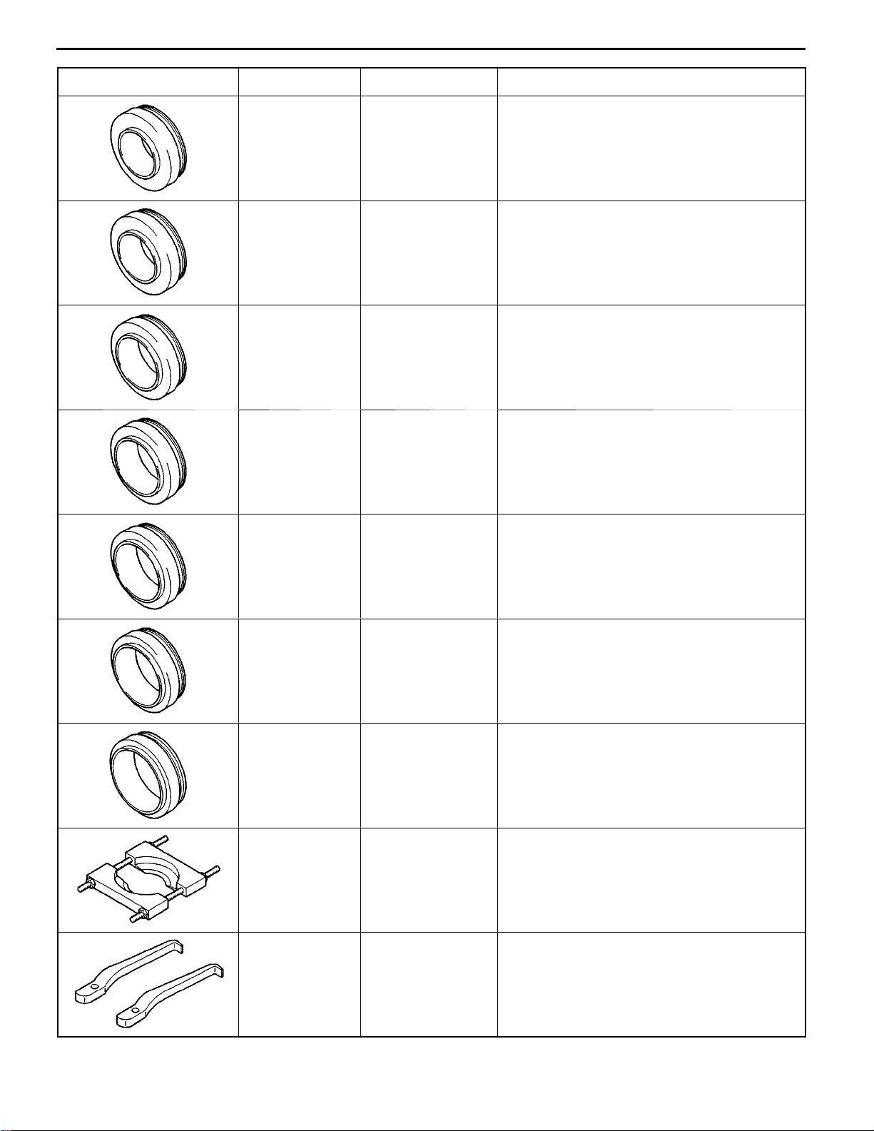
Tool UseNameNumber
Special Tools
22B-2-3
MD998819 Installer adapter
(40)
MD998820 Installer adapter
(42)
MD998822 Installer adapter
(46)
MD998823 Installer adapter
(48)
Installation of 5th-reverse speed synchronizer
hub, differential case bearing, 4th speed gear
and 5th speed gear sleeve <F5M42, W5M42>
Installation of 5th speed gear sleeve, 2nd
speed gear sleeve <F5M41>
Installation of 1st speed gear sleeve,1st-2nd
speed synchronizer hub <F5M41>, 2nd speed
gear sleeve and 3rd speed gear <F5M42,
W5M42>
Installation of differential case taper roller
bearing inner race <F5M42, W5M42>
MD998824 Installer adapter
(50)
MD998825 Installer adapter
(52)
MD998826 Installer adapter
(54)
MD998917 Bearing remover Installation and removal of gears, bearings and
Installation of 4th speed gear sleeve and 5th
speed gear <F5M42, W5M42>
Installation of 1st-2nd speed synchronizer hub,
3rd-4th speed synchronizer hub and 1st speed
gear sleeve <F5M42, W5M42>
Installation of 3rd-4th speed synchronizer hub
<F5M41>
sleeves
MD999566 Claw Removal of differentialcase taper roller bearing
outer race <F5M42, W5M42>
E
Jun. 1998Mitsubishi Motors Corporation Revised
PWEE9508-E
Page 30
22B-2-4
MANUAL TRANSMISSION (E-W) -
TRANSFER
Tool Number Name Use
Special Tools
MB990887 Arm bush remover
and installer ring
MB990891 Arm bush remover
and installer base
MB990933 Installer adapter Installation of transfer cover oil seal
MD998304 Oil seal installer Installation of transfer extension housing oil
Installation of transfer oil seal
Installation of transfer oil seal
seal
MD998800 Oil seal installer Installation of transfer cover oil seal
E
Jun. 1998Mitsubishi Motors Corporation Added
PWEE9508-E
Page 31

MANUAL TRANSMISSION (E–W) – Transmission <F5M41>
3. TRANSMISSION <F5M41>
DISASSEMBLY AND REASSEMBLY
18 Nm
22B-3-1
32 Nm
5
70 Nm
3
3.9 Nm
2
4
8
9
6
10
11
7
70 Nm
1
1
Disassembly steps
1. Roll stopper bracket
2. Insulator washer <some model>
3. Shift cable bracket
"MA 4. Select lever
"LA 5. Speedometer gear
6. Back-up lamp switch
7. Gasket
8. Restrict ball
9. Gasket
10. Poppet spring
11. Gasket
Nov. 1995Mitsubishi Motors Corporation Added
E
E
Dec. 2000Mitsubishi Motors Corporation Revised
PWEE9508-A
PWEE9508-H
Page 32

22B-3-2
MANUAL TRANSMISSION (E–W) – Transmission <F5M41>
Apply gear oil to all
moving parts before
installation.
24
18 Nm
27
44 Nm
25
26
14
18 Nm
15
30 Nm
12
13
18
19
17
16
48 Nm
Disassembly steps
12. Interlock plate bolt
13. Gasket
"KA 14. Control housing
15. Neutral return spring
"JA 16. Reverse idler gear shaft bolt
17. Gasket
AA""IA 18. Sealing cap
AB""HA 19. Transmission case
23
22
20
21
AC""GA 20. Reverse idler gear shaft
21. Reverse idler gear
22. Reverse shift lever shoe
23. Reverse shift lever
"FA 24. Oil guide
25. Magnet holder
26. Magnet
"EA 27. Spacer
TFM0719
E
E
Nov. 1995Mitsubishi Motors Corporation Added
Dec. 2000Mitsubishi Motors Corporation Revised
PWEE9508-A
PWEE9508-H
Page 33

MANUAL TRANSMISSION (E-W) -
Lubricate all internal
parts with gear oil during reassembly.
45
31
29
Transmission <F5M41>
30
32
41
22B-3-3
33
46
40
35
36
34
39
38
37
18 Nm
42
44
43
"DA
"DA
"DA
AD""CA
AD""CA
AD""CA
AD""CA
E
Disassembly steps
29. Spring pin
30. 1st-2nd speed shift rail
31. 1st-2nd speed shift fork
32. Spring pin
33. Spring pin
34. 5th speed shift rail
35. 5th speed shift fork
36. Reverse shift lug
37. Snap ring
Nov. 1995Mitsubishi Motors Corporation Added
AD""CA
AD""CA
AD""CA
AD""CA
AE""AA
AE""AA
PWEE9508-A
"BA
TFM0720
38. Reverse interlock rail
39. Steel ball
40. 3rd-4th speed shift rail
41. 3rd-4th speed shift fork
42. Front bearing retainer
43. Input shaft
44. Output shaft
45. Differential
46. Clutch housing
Page 34

22B-3-4
MANUAL TRANSMISSION (E-W) -
DISASSEMBLY SERVICE POINTS
Sealing cap
AA"
SEALING CAP REMOVAL
Transmission <F5M41>
Snap ring
3rd-4th speed synchronizer sleeve
Reverse shift lug
AB"
TRANSMISSION CASE REMOVAL
Expand the snap ring to remove it from the snap ring groove
of the ball bearing.
NOTE
Expansion of the snap ring causes the snap ring groove to
get out of position because of the output shaft’s own weight.
AC"
REVERSE IDLER GEAR SHAFT REMOVAL
Shift the 3rd-4th speed synchronizer sleeve toward the 4th
speed side.
AD"
3RD-4TH SPEED SHIFT RAIL / 3RD-4TH SPEED
SHIFT FORK / 5TH SPEED SHIFT FORK / SNAP
RING / REVERSE SHIFT LUG / 5TH SPEED
SHIFT RAIL / STEEL BALL / REVERSE
INTERLOCK RAIL REMOVAL
(1) While sliding the reverse shift lug in the direction shown,
remove the 5th speed shift fork, 5th speed shift rail, reverse
shift lug, snap ring, steel ball and reverse interlock rail.
E
3rd-4th
speed
shift rail
(2) While sliding the 3rd-4th speed shift rail in the direction
shown, remove it together with the shift fork.
Nov. 1995Mitsubishi Motors Corporation Added
PWEE9508-A
Page 35

Output shaft
MANUAL TRANSMISSION (E–W) – Transmission <F5M41>
AE" INPUT SHAFT / OUTPUT SHAFT REMOVAL
Remove the input and output shafts together.
Input shaft
22B-3-5
Solders
Detent
ADJUSTMENT BEFORE REASSEMBLY
SPACER SELECTION FOR DIFFERENTIAL CASE END
PLAY ADJUSTMENT
(1) Put solders (about 10 mm long, 1.6 mm in diameter) in
the illustrated positions of the transmission case and install
the differential.
(2) Install the clutch housing and tighten the bolts to the
specified torque.
(3) If the solders are not crushed, put larger diameter solders
and repeat Steps (1) and (2).
(4) Measure the thickness (T) of the crushed solder with a
micrometer and select a spacer according to the following
equation.
Spacer thickness:
(T – 0.05 mm) to (T – 0.17 mm)
REASSEMBLY SERVICE POINTS
"AA OUTPUT SHAFT / INPUT SHAFT INSTALLATION
<F5M41 with reverse brake>
While placing the reverse brake cone detent in the illustrated
position, install the input and output shafts together.
"BA FRONT BEARING RETAINER INSTALLATION
Apply a sealant to the front bearing retainer mounting bolts
(countersunk bolts only).
Specified sealant:
3M STUD Locking No. 4170 or equivalent
5 – 7 mm
2 – 3 mm
E
E
Nov. 1995Mitsubishi Motors Corporation Added
Dec. 2000Mitsubishi Motors Corporation Revised
PWEE9508-A
PWEE9508-H
Page 36

22B-3-6
MANUAL TRANSMISSION (E-W) -
Transmission <F5M41>
3rd-4th
speed
shift rail
5th
speed
shift rail
Reverse shift lug
Snap ring
3rd-4th
speed
shift
fork
5th speed shift fork
Reverse interlock
rail
Steel ball
(inside)
"CA
REVERSE INTERLOCK RAIL / STEEL BALL /
5TH SPEED SHIFT RAIL / REVERSE SHIFT LUG
/ SNAP RING / 5TH SPEED SHIFT FORK /
3RD-4TH SPEED SHIFT FORK / 3RD-4TH SPEED
SHIFT RAIL INSTALLATION
(1) Install the 3rd-4th shift rail and fork.
(2) Install the reverse interlock rail, steel ball, 5th speed shift
rail, 5th speed shift fork, reverse shift lug and snap ring
in the illustrated positions.
Reverse
shift lug
Snap ring
5th speed shift rail
Reverse
shift lug
Reverse
interlock rail
Steel ball
(3) While sliding the reverse shift lug in the direction shown,
install the 5th speed shift fork, 5th speed shift rail, reverse
shift lug, snap ring, steel ball and reverse interlock rail.
"DA
SPRING PIN INSTALLATION
E
Nov. 1995Mitsubishi Motors Corporation Added
PWEE9508-A
Page 37

MANUAL TRANSMISSION (E-W) -
Transmission <F5M41>
22B-3-7
Oil guide
"EA
SPACER INSTALLATION
Install the spacer selected in the section “ADJUSTMENT
BEFORE REASSEMBLY”.
"FA
"GA
OIL GUIDE INSTALLATION
REVERSE IDLER GEAR SHAFT INSTALLATION
(1) Shift the 3rd-4th speed synchronizer sleeve toward the
4th speed side.
3rd-4th speed synchronizer sleeve
Reverse
idler gear
shaft
(2) Face the threaded hole of the reverse idler gear shaft
toward the direction shown.
"HA
TRANSMISSION CASE INSTALLATION
(1) Apply a 1.5 mm bead of sealant to the illustrated positions
of the transmission case.
Specified sealant:
MITSUBISHI genuine sealant part No. MD997740
or equivalent
Caution
Squeeze out the sealant uniformly, while making sure
that it is not broken or excessively applied.
E
Nov. 1995Mitsubishi Motors Corporation Added
PWEE9508-A
Page 38

22B-3-8
Snap ring
MANUAL TRANSMISSION (E-W) -
(2) Install the transmission case and expand the snap ring.
(3) Tighten the transmission case mounting bolts to the
specified torque.
NOTE
Place the transmission upside down and let the snap ring
fit in the groove by taking advantage of the output shaft’s
own weight.
Transmission <F5M41>
MB990938
MB990927
Sealing cap
"IA
SEALING CAP INSTALLATION
Press-fit the sealingcap all the way up to the illustrated position.
"JA
REVERSE IDLER GEAR SHAFT BOLT
INSTALLATION
Using a screwdriver (8 mm in shaft diameter), center the bolt
hole.
"KA
CONTROL HOUSING INSTALLATION
Apply a 1.5 mm bead of sealant to the illustrated position
of the transmission case.
Specified sealant:
MITSUBISHI genuine sealant part No. MD997740 or
equivalent
Caution
Squeeze outthesealantuniformly, while making sure that
it is not broken or excessively applied.
E
Nov. 1995Mitsubishi Motors Corporation Added
PWEE9508-A
Page 39

MANUAL TRANSMISSION (E-W) -
Transmission <F5M41>
22B-3-9
O-ring
Control shaft
Select
lever
shoe
"LA
SPEEDOMETER GEAR INSTALLATION
Apply transmission oil to the O-ring of the speedometer gear.
Transmission oil:
Hypoid gear oil SAE 75W-85W conforming to API
classification GL-4 or higher
"MA
SELECT LEVER INSTALLATION
Apply grease to the control shaft sliding portion of the select
lever shoe.
Specified grease:
MITSUBISHI genuine grease part No. 0101011 or
equivalent
INSPECTION
BACK-UP LAMP SWITCH
Check for continuity between terminals.
Switch condition Continuity
Pressed Not exist
Released Exists
E
Nov. 1995Mitsubishi Motors Corporation Added
PWEE9508-A
Page 40

MANUAL TRANSMISSION (E–W) – Transmission <F5M42, W5M42>
4. TRANSMISSION <F5M42, W5M42>
DISASSEMBLY AND REASSEMBLY
18 Nm
22B-4-1
Apply gear oil to all
moving parts before
installation.
32 Nm
70 Nm
3
5
7
3.9 Nm
2
6
4
8
9
10
11
22 Nm
16
15
14
12
3
18 Nm
13
1
70 Nm
69 Nm
Disassembly steps
1. Transfer <W5M42>
2. O-ring <W5M42>
3. Roll stopper bracket
4. Insulator washer <some model>
5. Shift cable bracket
"KA 6. Select lever
"JA 7. Speedometer gear
8. Back-up lamp switch
9. Gasket
10. Poppet spring
11. Gasket
12. Connector bracket <For GDI engine except DA2A>
13. Clutch fluid line blacket <DA2A only>
14. Oil temperature sensor harness <For GDI engine only>
15. Oil temperature sensor <For GDI engine only>
16. Gasket <For GDI engine only>
E
Dec. 2000Mitsubishi Motors Corporation Revised
PWEE9508-H
TFM1069
Page 41

22B-4-2
Apply gear oil to all
moving parts before
installation.
MANUAL TRANSMISSION (E–W) – Transmission <F5M42, W5M42>
19
18 Nm
30 Nm
20
17
27
28
44 Nm
29
30
24
18
25
26
22
23
48 Nm
21
6.9 Nm
Disassembly steps
17. Interlock plate bolt
18. Gasket
"IA 19. Control housing
20. Neutral return spring
"HA 21. Under cover
22. Reverse idler gear shaft bolt
23. Gasket
24. Reverse idler gear
AA""GA 25. Sealing cap
AB""FA 26. Transmission case
"EA 27. Outer race
"DA 28. Spacer
29. Magnet holder
30. Magnet
E
Dec. 2000Mitsubishi Motors Corporation Revised
TFM0597
PWEE9508-H
Page 42

MANUAL TRANSMISSION (E-W) -
Apply gear oil to all
moving parts before
installation.
30
32
42
Transmission <F5M42, W5M42>
31
33
34
36
22B-4-3
38
43
35
41
39
37
18 Nm
40
Disassembly steps
"CA 30. Spring pin
31. 1st-2nd speed shift rail
32. 1st-2nd speed shift fork
"CA 33. Spring pin
"CA 34. Spring pin
AC""BA 35. 3rd-4th speed shift rail
AC""BA 36. 3rd-4th speed shift fork
AC""BA 37. 5th-reverse speed shift rail
AC""BA 38. 5th-reverse speed shift fork
39. Front bearing retainer
AD""AA 40. Input shaft
AD""AA 41. Output shaft
42. Differential
43. Clutch housing
E
Jun. 1998Mitsubishi Motors Corporation Revised
TFM0598
PWEE9508-E
Page 43

22B-4-4
MANUAL TRANSMISSION (E-W) -
DISASSEMBLY SERVICE POINTS
Sealing cap
AA"
Drive a screwdriver into the sealing cap at the center, then
pry off the sealing cap with the screwdriver.
SEALING CAP REMOVAL
Transmission <F5M42, W5M42>
Snap ring
5th-reverse
speed shift
fork
3rd-4th speed
shift rail
3rd-4th speed
shift fork
5th-reverse
speed shift rail
AB"
TRANSMISSION CASE REMOVAL
Expand the snap ring to remove it from the snap ring groove
of the ball bearing.
NOTE
Expansion of the snap ring causes the snap ring groove to
get out of position because of the output shaft’s own weight.
AC"
3RD-4TH SPEED SHIFT RAIL / 3RD-4TH SPEED
SHIFT FORK / 5TH-REVERSE SPEED SHIFT RAIL
/ 5TH-REVERSE SPEED SHIFT FORK REMOVAL
(1) Shift the 3rd-4th speed shift fork and 5th-reverse speed
shift fork in the direction shown.
(2) Slide the 3rd-4th speed shift rail and 5th-reverse speed
shift rail in the direction shown and remove them together
with the shift fork.
Output shaft
E
AD"
Input shaft
Jun. 1998Mitsubishi Motors Corporation Revised
Remove the input and output shafts together.
INPUT SHAFT / OUTPUT SHAFT REMOVAL
PWEE9508-E
Page 44

MANUAL TRANSMISSION (E-W) -
Transmission <F5M42, W5M42>
22B-4-5
Output shaft
Solders
Input shaft
ADJUSTMENT BEFORE REASSEMBLY
SPACER SELECTION FOR DIFFERENTIAL CASE
PRELOAD ADJUSTMENT
(1) Put solders (about 10 mm long, 1.6 mm in diameter) in
the illustrated positions of the transmission case and install
the bearing outer race and differential.
(2) Install the clutch housing and tighten the bolts to the
specified torque.
(3) If the solders are not crushed, put larger diameter solders
and repeat Steps (1) and (2).
(4) Measure the thickness (T) of the crushed solder with a
micrometer and select a spacer according to the following
equation.
Spacer thickness:
(T + 0.05 mm) to (T + 0.11 mm)
REASSEMBLY SERVICE POINTS
"AA
Install the input and output shafts together.
OUTPUT SHAFT / INPUT SHAFT INSTALLATION
5th-reverse
speed synchronizer sleeve
5th-reverse
speed shift
fork
E
3rd-4th
speed
synchronizer
sleeve
"BA
5TH-REVERSE SPEED SHIFT FORK /
5TH-REVERSE SPEED SHIFT RAIL / 3RD-4TH
SPEED SHIFT FORK / 3RD-4TH SPEED SHIFT
RAIL INSTALLATION
(1) Shift the 3rd-4th speed synchronizer sleeve and
5th-reverse speed synchronizer sleeve in the direction
shown.
(2) Install the 3rd-4th speed shift rail and fork and the
3rd-4th speed shift rail
3rd-4th speed shift fork
5th-reverse
speed shift rail
Jun. 1998Mitsubishi Motors Corporation Revised
5th-reverse speed shift rail and fork.
PWEE9508-E
Page 45

22B-4-6
3rd-4th speed
shift rail
MANUAL TRANSMISSION (E-W) -
(3) While fitting each shift fork in the sleeve, slide the shift
5th-reverse
speed shift rail
rails in the direction shown and install.
Transmission <F5M42, W5M42>
Shift rail
Spring pin
MB990938
Shift fork
Slit
2.5 mm
"CA
SPRING PIN INSTALLATION
Install the spring pin such that its slit may face in the axial
direction of the shift rail.
"DA
SPACER INSTALLATION
Install the spacer selected in the section “ADJUSTMENT
BEFORE REASSEMBLY”.
"EA
OUTER RACE INSTALLATION
Use th e special tools to install the outer race.
MB990935
E
"FA
TRANSMISSION CASE INSTALLATION
(1) Apply a 1.5 mm bead of sealant to the illustrated position
of the transmission case.
Specified sealant:
MITSUBISHI genuine sealant part No. MD997740
or equivalent
Caution
Squeeze out the sealant uniformly, while making sure
that it is not broken or excessively applied.
Jun. 1998Mitsubishi Motors Corporation Revised
PWEE9508-E
Page 46

Snap ring
MANUAL TRANSMISSION (E-W) -
(2) Install the transmission case and expand the snap ring.
(3) Tighten the transmission case to the specified torque.
NOTE
Place the transmission upside down a nd let the snap ring
fit in the groove by taking advantage of the output shaft’s
own weight.
Transmission <F5M42, W5M42>
22B-4-7
MB990938
MB990927
Sealing cap
"GA
SEALING CAP INSTALLATION
Press-fit the sealingcap all the way up to the illustrated position.
"HA
UNDER COVER INSTALLATION
Apply a 1.5 mm bead of sealant to the illustrated position
of the transmission case.
Specified sealant:
MITSUBISHI genuine sealant part No. MD997740 or
equivalent
Caution
Squeeze outthesealantuniformly, while making sure that
it is not broken or excessively applied.
"IA
CONTROL HOUSING INSTALLATION
Apply a 1.5 mm bead of sealant to the illustrated position
of the transmission case.
Specified sealant:
MITSUBISHI genuine sealant part No. MD997740 or
equivalent
Caution
Squeeze outthesealantuniformly, while making sure that
it is not broken or excessively applied.
E
Jun. 1998Mitsubishi Motors Corporation Revised
PWEE9508-E
Page 47

22B-4-8
MANUAL TRANSMISSION (E-W) -
Transmission <F5M42, W5M42>
O-ring
Control shaft
Select
lever shoe
"JA
SPEEDOMETER GEAR INSTALLATION
Apply transmission oil to the O-ring of the speedometer gear.
Transmission oil:
Hypoid gear oil SAE 75W-85W conforming to API
classification GL-4 or higher
"KA
SELECT LEVER INSTALLATION
Apply grease to the control shaft sliding portion of the select
lever shoe.
Specified grease:
MITSUBISHI genuine grease part No. 0101011 or
equivalent
Transmission oil
INSPECTION
BACK-UP LAMP SWITCH
(1) Check for continuity between terminals.
Switch condition Continuity
Pressed Not exist
Released Exists
(2) If the above requirements are not met, replace the back-up
lamp switch with a new one.
OIL TEMPERATURE SENSOR <For GDI engine only>
(1) Check for continuity between terminals.
Temperature (°C) Standard value (kW)
20 2.31 - 2.59
110 0.1451 - 0.1491
(2) If the standard value is not met, replace the oil temperature
sensor with a new one.
E
Jun. 1998Mitsubishi Motors Corporation Revised
PWEE9508-E
Page 48

MANUAL TRANSMISSION (E-W) -
Input Shaft <F5M41>
5. INPUT SHAFT <F5M41>
DISASSEMBLY AND REASSEMBLY <Models with reverse brake>
22B-5-1
Apply gear oil to all
moving parts before
installation.
27
25
29
13
28
24
22
23
21
20
15
17
19
16
18
1
2
4
5
6
7
3
25
26
14
13
Disassembly steps
"MA 1. Snap ring
AA""LA 2. Ball bearing
AB""KA 3. Reverse brake sleeve
4. Needle roller bearing
5. Reverse brake cone
6. Reverse brake ring
"DA 7. Synchronizer spring
"JA 8. Synchronizer sleeve
AC""IA 9. 5th-reverse speed synchronizer hub
10. Synchronizer ring
"DA 11. Synchronizer spring
12. 5th speed gear
13. Needle roller bearing
AD""HA 14. 5th speed gear sleeve
8
9
11
10
12
TFM0834
15. 4th speed gear
16. Needle roller bearing
AE""GA 17. 4th speed gear sleeve
18. Synchronizer ring
"DA 19. Synchronizer spring
"FA 20. Synchronizer sleeve
"EA 21. 3rd-4th speed synchronizer hub
22. Synchronizer ring
"DA 23. Synchronizer spring
24. 3rd speed gear
25. Needle roller bearing
"CA 26. Snap ring
AF""BA 27. Ball bearing
"AA 28. Oil seal
29. Input shaft
E
July 1999Mitsubishi Motors Corporation Revised
PWEE9508-F
Page 49

22B-5-2
MANUAL TRANSMISSION (E-W) -
Input Shaft <F5M41>
DISASSEMBLY AND REASSEMBLY <Except models with reverse brake>
14
Apply gear oil to all
moving parts before
installation.
17
19
18
20
21
15
16
22
23
13
12
21
11
25
10
2
24
9
5
7
1
3
4
6
8
9
Disassembly steps
"MA 1. Snap ring
AA""LA 2. Ball bearing
3. Collar
"JA 4. Synchronizer sleeve
AC""IA 5. 5th-reverse speed synchronizer hub
6. Synchronizer ring
"DA 7. Synchronizer spring
8. 5th speed gear
9. Needle roller bearing
AD""HA 10. 5th speed gear sleeve
11. 4th speed gear
12. Needle roller bearing
AE""GA 13. 4th speed gear sleeve
E
July 1999Mitsubishi Motors Corporation Revised
14. Synchronizer ring
"DA 15. Synchronizer spring
"FA 16. Synchronizer sleeve
"EA 17. 3rd-4th speed synchronizer hub
18. Synchronizer ring
"DA 19. Synchronizer spring
20. 3rd speed gear
21. Needle roller bearing
"CA 22. Snap ring
AF""BA 23. Ball bearing
"AA 24. Oil seal
25. Input shaft
PWEE9508-F
Page 50

MANUAL TRANSMISSION (E–W) – Input Shaft <F5M41>
DISASSEMBLY AND REASSEMBLY <Models with synchronizer lever>
14
Apply gear oil to all
moving parts before
installation.
17
19
18
20
21
15
16
22B-5-2a
22
23
13
12
21
11
25
10
2
24
5
9
7
1
3
4
6
8
9
Disassembly steps
"MA 1. Snap ring
AA""LA 2. Ball bearing
3. Collar
"JA 4. Synchronizer sleeve
AC""IA 5. 5th-reverse speed synchronizer hub
6. Synchronizer ring
7. Synchronizer lever
8. 5th speed gear
9. Needle roller bearing
AD""HA 10. 5th speed gear sleeve
11. 4th speed gear
12. Needle roller bearing
AE""GA 13. 4th speed gear sleeve
E
Dec. 2000Mitsubishi Motors Corporation Revised
14. Synchronizer ring
"DA 15. Synchronizer spring
"FA 16. Synchronizer sleeve
"EA 17. 3rd-4th speed synchronizer hub
18. Synchronizer ring
"DA 19. Synchronizer spring
20. 3rd speed gear
21. Needle roller bearing
"CA 22. Snap ring
AF""BA 23. Ball bearing
"AA 24. Oil seal
25. Input shaft
PWEE9508-H
Page 51

22B-5-2b
MD998801
MANUAL TRANSMISSION (E–W) – Input Shaft <F5M41>
DISASSEMBLY SERVICE POINTS
AA" BALL BEARING REMOVAL
MD998801
MD998917
MD998917
AB" REVERSE BRAKE SLEEVE REMOVAL
Mount a special tool on the 5th speed gear and remove the
reverse brake sleeve.
AC" 5TH-REVERSE SPEED SYNCHRONIZER HUB
REMOVAL
Mount a special tool on the 5th speed gear and remove the
5th-reverse synchronizer hub.
AD" 5TH SPEED GEAR SLEEVE REMOVAL
Mount a special tool on the 4th speed gear and remove the
5th speed gear sleeve.
E
MD998801
AE" 4TH SPEED GEAR SLEEVE REMOVAL
Mount a special tool on the 3rd speed gear and remove the
4th speed gear sleeve.
Dec. 2000Mitsubishi Motors Corporation Revised
PWEE9508-H
Page 52

MANUAL TRANSMISSION (E-W) -
Input Shaft <F5M41>
22B-5-3
MD998801
Oil seal
3.5 mm
MD998812
AF"
BALL BEARING REMOVAL
REASSEMBLY SERVICE POINTS
"AA
Drive in the oil seal all the way up to the illustrated dimension.
"BA
OIL SEAL INSTALLATION
BALL BEARING INSTALLATION
MD998801
Snap ring
MD998813
MD998817
"CA
SNAP RING INSTALLATION
Select and install a snap ring so that the input shaft front
bearing end play will have the standard value.
Standard value:
-0.01-0.12 mm
"DA
SYNCHRONIZER SPRING INSTALLATION
Install the synchronizer spring securely up to the illustrated
position of the synchronizer ring.
Synchronizer spring
E
Nov. 1995Mitsubishi Motors Corporation Added
PWEE9508-A
Page 53

22B-5-4
MANUAL TRANSMISSION (E-W) -
Input Shaft <F5M41>
Identification mark
MD998801
Identification
groove
Rear of
transmission
MD998812
MD998813
MD998826
"EA
3RD-4TH SPEED SYNCHRONIZER HUB
INSTALLATION
Install the 3rd-4th speed synchronizer hub in such a way that
it will be oriented in the direction shown.
Caution
Whenthe hubis installed,make surethat thesynchronizer
ring is not caught.
"FA
SYNCHRONIZER SLEEVE INSTALLATION
(1) Install the synchronizer sleeve in such a way that it will
be oriented in the direction shown.
MD998801
Synchronizer hub
Rear of
transmission
Synchronizer
sleeve
MD998812
MD998813
MD998824
(2) When the synchronizer sleeve is installed, make sure that
the deep groove portion of the synchronizer hub is aligned
with the projecting portion of the sleeve.
"GA
4TH SPEED GEAR SLEEVE INSTALLATION
E
Nov. 1995Mitsubishi Motors Corporation Added
PWEE9508-A
Page 54

MANUAL TRANSMISSION (E-W) -
Input Shaft <F5M41>
22B-5-5
MD998801
Identification mark
MD998812
MD998813
MD998820
Rear of
transmission
MD998812
MD998819
"HA
"IA
5TH SPEED GEAR SLEEVE INSTALLATION
5TH-REVERSE SPEED SYNCHRONIZER HUB
INSTALLATION
Install the 5th-reverse speed synchronizer hub in such a way
that it will be oriented in the direction shown.
Caution
Whenthe 5th-reverse speedsynchronizer hubis installed,
make sure that the synchronizer ring is not caught.
MD998801
Identification
groove
Rear of
transmission
Synchronizer
sleeve
"JA
SYNCHRONIZER SLEEVE INSTALLATION
(1) Install the synchronizer sleeve in such a way that it will
be oriented in the direction shown.
(2) When the synchronizer sleeve is installed, make sure that
the deep groove portion of the synchronizer hub is aligned
with the projecting portion of the sleeve.
Synchronizer hub
E
Nov. 1995Mitsubishi Motors Corporation Added
PWEE9508-A
Page 55

22B-5-6
MANUAL TRANSMISSION (E-W) -
Input Shaft <F5M41>
MD998801
MD998801
MD998812
MD998818
MD998812
MD998818
"KA
"LA
"MA
REVERSE BRAKE SLEEVE INSTALLATION
BALL BEARING INSTALLATION
SNAP RING INSTALLATION
Select and install a snap ring so that the input shaft rear
bearing end play will have the standard value.
Standard value:
-0.01-0.09 mm
INSPECTION
INPUT SHAFT
(1) Check theoutside diameter of theneedle bearingmounting
portion for damage, abnormal wear and seizure.
(2) Check the splines for damage and wear.
NEEDLE ROLLER BEARING
(1) Check to ensure that when the input shaft, sleeve and
gear are combined and made to rotate, they rotate
smoothly without noise.
(2) Check to ensure that the cage is not deformed.
E
Nov. 1995Mitsubishi Motors Corporation Added
PWEE9508-A
Page 56

MANUAL TRANSMISSION (E-W) -
SYNCHRONIZER RING
(1) Check to ensure that the clutch gear tooth surfaces are
not damaged and broken.
(2) Check to ensure that the cone inside diameter is not
damaged or worn and that the threads are not crushed.
Input Shaft <F5M41>
22B-5-7
A
Synchronizer ring Gear
(3) Press the synchronizer ring against the gear and check
clearance “A”. If “A” is less than the limit, replace.
Limit: 0.5 mm
SYNCHRONIZER SLEEVE AND HUB
(1) Check to ensure that when the synchronizer sleeve and
hub are combined and made to slide, they slide smoothly
without binding.
(2) Check to ensure that the front and rear ends of the sleeve
inside surface are not damaged.
SYNCHRONIZER SPRING
Check to ensure that the spring is not sagging, deformed
or broken.
SPEED GEARS
(1) Check to ensure that the helical and clutch gear tooth
surfaces are not damaged or worn.
(2) Check to ensure that the synchronizer cone surfaces are
not roughened, damaged or worn.
(3) Check to ensure that the gear inside diameter and front
and rear surfaces are not damaged and worn.
E
E
Nov. 1995Mitsubishi Motors Corporation Added
Jun. 2000Mitsubishi Motors Corporation Revised
PWEE9508-A
PWEE9508-G
Page 57

MANUAL TRANSMISSION (E-W) -
6. INPUT SHAFT <F5M42, W5M42>
DISASSEMBLY AND REASSEMBLY
Apply gear oil to all
moving parts before
installation.
15
16
Input Shaft <F5M42, W5M42>
9
10
11
12
14
13
22B-6-1
18
17
Disassembly steps
"LA 1. Snap ring
AA""KA 2. Ball bearing
"JA 3. Thrust plate stopper
"IA 4. Thrust plate
AB""HA 5. 5th speed gear
6. 4th speed gear
7. Needle roller bearing
AC""GA 8. 4th speed gear sleeve
9. Synchronizer ring
"DA 10. Synchronizer spring
16
20
19
6
7
8
"FA 11. Synchronizer sleeve
"EA 12. 3rd-4th speed synchronizer hub
13. Synchronizer ring
"DA 14. Synchronizer spring
15. 3rd speed gear
16. Needle roller bearing
"CA 17. Snap ring
AD""BA 18. Ball bearing
"AA 19. Oil seal
20. Input shaft
2
4
1
3
5
TFM0591
E
Jun. 1998Mitsubishi Motors Corporation Revised
PWEE9508-E
Page 58

22B-6-2
MANUAL TRANSMISSION (E-W) -
Input Shaft <F5M42, W5M42>
MD998801
MD998801
MD998801
DISASSEMBLY SERVICE POINTS
AA"
Use th e special tool to remove the ball bearing.
AB"
Use the special tool to remove the 5th speed gear.
AC"
Mount a special tool on the 3rd gear and remove the 4th
speed gear sleeve.
BALL BEARING REMOVAL
5TH SPEED GEAR REMOVAL
4TH SPEED GEAR SLEEVE REMOVAL
MD998801
E
Oil seal
AD"
BALL BEARING REMOVAL
Use th e special tool to remove the ball bearing.
REASSEMBLY SERVICE POINTS
3.5 mm
"AA
Drive in the oil seal all the way up to the illustrated dimension.
Jun. 1998Mitsubishi Motors Corporation Revised
OIL SEAL INSTALLATION
PWEE9508-E
Page 59

MANUAL TRANSMISSION (E-W) -
Input Shaft <F5M42, W5M42>
22B-6-3
MD998801
Snap ring
MD998812
MD998813
MD998816
"BA
BALL BEARING INSTALLATION
Use th e special tools to install the ball bearing.
"CA
SNAP RING INSTALLATION
Select and install a snap ring so that the input shaft front
bearing end play will have the standard value.
Standard value:
-0.01-0.12 mm
"DA
SYNCHRONIZER SPRING INSTALLATION
Install the synchronizer spring securely up to the illustrated
position of the synchronizer ring.
Synchronizer spring
Identification mark
MD998801
Rear of
transmission
MD998812
MD998813
MD998825
"EA
3RD-4TH SPEED SYNCHRONIZER HUB
INSTALLATION
Install the 3rd-4th speed synchronizer hub in such a way that
it will be oriented in the direction shown.
Caution
Whenthe hubis installed,make surethat thesynchronizer
ring is not caught.
E
Jun. 1998Mitsubishi Motors Corporation Revised
PWEE9508-E
Page 60

22B-6-4
MANUAL TRANSMISSION (E-W) -
Input Shaft <F5M42, W5M42>
Identification
groove
Synchronizer hub
Rear of transmission
Synchronizer sleeve
MD998812
"FA
SYNCHRONIZER SLEEVE INSTALLATION
(1) Install the synchronizer sleeve in such a way that it will
be oriented in the direction shown.
(2) When the synchronizer sleeve is installed, make sure that
the deep groove portion of the synchronizer hub is aligned
with the projecting portion of the sleeve.
"GA
4TH SPEED GEAR SLEEVE INSTALLATION
Use the special tools to install the 4th speed gear sleeve.
MD998801
MD998801
MD998813
MD998824
MD998812
MD998813
MD998824
"HA
5TH SPEED GEAR INSTALLATION
Use the special tools to install the 5th speed gear.
"IA
THRUST PLATE INSTALLATION
Select and install a thrust plate so that the input shaft 5th
speed gear end play will have the standard value.
Thrust plate
E
Standard value:
-0.01-0.09 mm
Jun. 1998Mitsubishi Motors Corporation Revised
PWEE9508-E
Page 61

MANUAL TRANSMISSION (E-W) -
Input Shaft <F5M42, W5M42>
22B-6-5
MD998801
Thrust plate stopper
Thrust plate
MD998812
MD998818
"JA
THRUST PLATE STOPPER INSTALLATION
When the thrust plate is installed, make sure that it is not
tilted.
"KA
BALL BEARING INSTALLATION
Use th e special tools to install the ball bearing.
"LA
SNAP RING INSTALLATION
Select and install a snap ring so that the input shaft rear
bearing end play will have the standard value.
Snap ring
Standard value:
-0.01-0.12 mm
INSPECTION
INPUT SHAFT
(1) Check theoutside diameter of theneedle bearingmounting
portion for damage, abnormal wear and seizure.
(2) Check the splines for damage and wear.
NEEDLE ROLLER BEARING
(1) Check to ensure that when the input shaft a n d gear are
combined and made to rotate, they rotate smoothly without
looseness and noise.
E
Jun. 1998Mitsubishi Motors Corporation Revised
PWEE9508-E
Page 62

22B-6-6
MANUAL TRANSMISSION (E-W) -
SYNCHRONIZER RING
(1) Check to ensure that the clutch gear tooth surfaces are
not damaged and broken.
(2) Check to ensure that the cone inside diameter is not
damaged or worn and that the threads are not crushed.
Input Shaft <F5M42, W5M42>
Synchronizer ring
A
(3) Press the synchronizer ring against the gear and check
clearance “A”. If “A” is less than the limit, replace.
Limit: 0.5 mm
Gear
SYNCHRONIZER SLEEVE AND HUB
(1) Check to ensure that when the synchronizer sleeve and
hub are combined and made to slide, they slide smoothly
without binding.
(2) Check to ensure that the front and rear ends of the sleeve
inside surface are not damaged.
SYNCHRONIZER SPRING
Check to ensure that the spring is not sagging, deformed
or broken.
SPEED GEARS
(1) Check to ensure that the helical and clutch gear tooth
surfaces are not damaged or worn.
(2) Check to ensure that the synchronizer cone surfaces are
not roughened, damaged or worn.
(3) Check to ensure that the gear inside diameter and front
and rear surfaces are not damaged and worn.
E
Jun. 2000Mitsubishi Motors Corporation Revised
PWEE9508-G
Page 63

MANUAL TRANSMISSION (E-W) -
Output Shaft <F5M41>
7. OUTPUT SHAFT <F5M41>
DISASSEMBLY AND REASSEMBLY
<Types with single synchronizer ring for 2nd gear>
Apply gear oil to all
moving parts before
installation.
19
22B-7-1
20
21
13
12
11
22
14
1
16
15
17
18
6
9
3
2
4
5
7
10
8
9
Disassembly steps
"JA 1. Snap ring
AA""IA 2. Ball bearing
3. Collar
4. 5th speed gear
5. 4th speed gear
"HA 6. Snap ring
7. 3rd speed gear
8. 2nd speed gear
9. Needle roller bearing
AB""GA 10. 2nd speed gear sleeve
11. Synchronizer ring
E
July 1999Mitsubishi Motors Corporation Revised
TFM0715
"DA 12. Synchronizer spring
"FA 13. Synchronizer sleeve
"EA 14. 1st-2nd speed synchronizer hub
15. Synchronizer ring
"DA 16. Synchronizer spring
17. 1st speed gear
18. Needle roller bearing
AC""CA 19. 1st speed gear sleeve
"BA 20. Snap ring
AD""AA 21. Roller bearing inner race
22. Output shaft
PWEE9508-F
Page 64

22B-7-2
MANUAL TRANSMISSION (E-W) -
Output Shaft <F5M41>
DISASSEMBLY AND REASSEMBLY
<Types with double synchronizer ring for 2nd gear>
Apply gear oil to all
moving parts before
installation.
21
22
15
23
13
11
12
24
16
1
18
17
19
20
6
9
3
2
4
5
7
10
8
9
14
Disassembly steps
"JA 1. Snap ring
AA""IA 2. Ball bearing
3. Collar
4. 5th speed gear
5. 4th speed gear
"HA 6. Snap ring
7. 3rd speed gear
8. 2nd speed gear
9. Needle roller bearing
AB""GA 10. 2nd speed gear sleeve
11. Inner synchronizer ring
12. Synchronizer cone
E
July 1999Mitsubishi Motors Corporation Revised
13. Outer synchronizer ring
"KA 14. Synchronizer spring
"FA 15. Synchronizer sleeve
"EA 16. 1st-2nd speed synchronizer hub
17. Synchronizer ring
"DA 18. Synchronizer spring
19. 1st speed gear
20. Needle roller bearing
AC""CA 21. 1st speed gear sleeve
"BA 22. Snap ring
AD""AA 23. Roller bearing inner race
24. Output shaft
PWEE9508-F
Page 65

MD998801
MANUAL TRANSMISSION (E-W) -
DISASSEMBLY SERVICE POINTS
AA"
BALL BEARING REMOVAL
Output Shaft <F5M41>
22B-7-2a
MD998917
MD998801
MD998917
Inner race
AB"
2ND SPEED GEAR SLEEVE REMOVAL
Mount a special tool on the synchronizer sleeve and remove
the 2nd speed gear sleeve.
AC"
AD"
1ST SPEED GEAR SLEEVE REMOVAL
ROLLER BEARING INNER RACE REMOVAL
E
MD998801
MD998812
MD998818
Inner
race
July 1999Mitsubishi Motors Corporation Added
REASSEMBLY SERVICE POINTS
"AA
ROLLER BEARING INNER RACE INSTALLATION
PWEE9508-F
Page 66

22B-7-2b
MANUAL TRANSMISSION (E-W) -
Output Shaft <F5M41>
Intentionally blank
E
July 1999Mitsubishi Motors Corporation Added
PWEE9508-F
Page 67

MANUAL TRANSMISSION (E-W) -
Output Shaft <F5M41>
22B-7-3
Snap ring
Sleeve
MD998812
MD998814
MD998822
"BA
SNAP RING INSTALLATION
Select and install a snap ring so that the output shaft front
bearing end play will have the standard value.
Standard value:
-0.01-0.12 mm
"CA
"DA
1ST SPEED GEAR SLEEVE INSTALLATION
SYNCHRONIZER SPRING INSTALLATION
Install the synchronizer spring securely up to the illustrated
position of the synchronizer ring.
Synchronizer spring
Identification mark
MD998812
MD998814
MD998822
Rear of transmission
"EA
1ST-2ND SPEED SYNCHRONIZER HUB
INSTALLATION
Install the 1st-2nd speed synchronizer hub in such a way
that it will be oriented in the direction shown.
Caution
Whenthe hubis installed,make surethat thesynchronizer
ring is not caught.
E
Nov. 1995Mitsubishi Motors Corporation Added
PWEE9508-A
Page 68

22B-7-4
MANUAL TRANSMISSION (E-W) -
Output Shaft <F5M41>
Rear of
transmission
Synchronizer sleeve
Synchronizer hub
MD998812
"FA
SYNCHRONIZER SLEEVE INSTALLATION
(1) Install the synchronizer sleeve in such a way that it will
be oriented in the direction shown.
(2) When the synchronizer sleeve is installed, make sure that
the deep groove portion of the synchronizer hub is aligned
with the projecting portion of the sleeve.
"GA
2ND SPEED GEAR SLEEVE INSTALLATION
Snap ring
MD998813
MD998812
MD998817
MD998820
"HA
SNAP RING INSTALLATION
Select and install a snap ring so that the output shaft 3rd
speed gear end play will have the standard value.
Standard value:
-0.01-0.09 mm
"IA
BALL BEARING INSTALLATION
E
Nov. 1995Mitsubishi Motors Corporation Added
PWEE9508-A
Page 69

MANUAL TRANSMISSION (E-W) -
Output Shaft <F5M41>
22B-7-5
Synchronizer
spring
"JA
SNAP RING INSTALLATION
Select and install a snap ring so that the output shaft rear
bearing end play will have the standard value.
Standard value:
-0.01-0.09 mm
"KA
SYNCHRONIZER SPRING INSTALLATION
Install the synchronizer spring securely inthe illustrated position
of t he outer synchronizer ring.
INSPECTION
OUTPUT SHAFT
Check the splines for damage and wear.
NEEDLE ROLLER BEARING
(1) Check to ensure that when the bearing sleeve and gear
are combined and made to rotate, they rotate smoothly
without looseness and noise.
(2) Check to ensure that the cage is not deformed.
SYNCHRONIZER RING
(1) Check to ensure that the clutch gear tooth surfaces are
not damaged and broken.
(2) Check to ensure that the cone inside diameter is not
damaged or worn and that the threads are not crushed.
E
E
Nov. 1995Mitsubishi Motors Corporation Added
July 1999Mitsubishi Motors Corporation Revised
PWEE9508-A
PWEE9508-F
Page 70

22B-7-6
MANUAL TRANSMISSION (E-W) -
Output Shaft <F5M41>
A
Synchronizer ring Gear
Gear
A
Outer ring
Cone
(3) Press the synchronizer ring against the gear and check
clearance “A”. If “A” is less than the limit, replace.
Limit: 0.5 mm
OUTER SYNCHRONIZER RING / INNER
SYNCHRONIZER RING / SYNCHRONIZER CONE
(1) Check to ensure that the clutch gear tooth surfaces and
cone surfaces are not damaged and broken.
(2) Install the outer ring, inner ring and cone, press them
against the gear, and check clearance “A”. If “A” is less
than the limit, replace.
Limit: 0.5 mm
Caution
When the outer ring, inner ring or cone has to be
replaced, make sure that the outer ring, inner ring
and cone are replaced as a set.
Inner ring
SYNCHRONIZER SLEEVE AND HUB
(1) Check to ensure that when the synchronizer sleeve and
hub are combined and made to slide, they slide smoothly
without binding.
(2) Check to ensure that the front and rear ends of the sleeve
inside surface are not damaged.
SYNCHRONIZER SPRING
Check to ensure that the spring is not sagging, deformed
or broken.
E
E
Nov. 1995Mitsubishi Motors Corporation Added
Jun. 2000Mitsubishi Motors Corporation Revised
PWEE9508-A
PWEE9508-G
Page 71

MANUAL TRANSMISSION (E-W) -
SPEED GEARS
(1) Check to ensure that the helical and clutch gear tooth
surfaces are not damaged or worn.
(2) Check to ensure that the synchronizer cone surfaces are
not roughened, damaged or worn.
(3) Check to ensure that the gear inside diameter and front
and rear surfaces are not damaged and worn.
Output Shaft <F5M41>
22B-7-7
E
E
Nov. 1995Mitsubishi Motors Corporation Added
July 1999Mitsubishi Motors Corporation Added
PWEE9508-A
PWEE9508-F
Page 72

MANUAL TRANSMISSION (E-W) -
Output Shaft <F5M42, W5M42>
22B-8-1
8. OUTPUT SHAFT <F5M42, W5M42>
DISASSEMBLY AND REASSEMBLY <Types with single synchronizer ring for 1st
gear and double synchronizer ring for 2nd gear>
18
Apply gear oil to all
moving parts before
installation.
31
30
29
21
22
23
24
25
26
28
27
19
20
4
34
33
32
12
15
17
16
Disassembly steps
"PA 1. Snap ring
AA""OA 2. Ball bearing
AB""NA 3. Reverse gear bearing sleeve
"NA 4. Needle roller bearing
"NA 5. Reverse gear
6. Synchronizer ring
"DA 7. Synchronizer spring
"FA 8. Synchronizer sleeve
AC""MA 9. 5th-reverse speed synchronizer hub
10. Synchronizer ring
"DA 11. Synchronizer spring
12. 5th speed gear
13. Needle roller bearing
"LA 14. 5th speed gear sleeve
"KA 15. 4th speed gear
"JA 16. Snap ring
AD""IA 17. 3rd speed gear
13
13
5
6
7
4
8
9
14
11
10
18. 2nd speed gear
19. Needle roller bearing
AE""HA 20. 2nd speed gear sleeve
21. Inner synchronizer ring
22. Synchronizer cone
23. Outer synchronizer ring
"GA 24. Synchronizer spring
"FA 25. Synchronizer sleeve
"EA 26. 1st-2nd speed synchronizer hub
27. Synchronizer ring
"DA 28. Synchronizer spring
29. 1st speed gear
30. Needle roller bearing
AF""CA 31. 1st speed gear sleeve
"BA 32. Snap ring
AG""AA 33. Roller bearing inner race
34. Output shaft
1
2
3
E
July 1999Mitsubishi Motors Corporation Revised
PWEE9508-F
Page 73

22B-8-2
MANUAL TRANSMISSION (E-W) -
Output Shaft <F5M42, W5M42>
DISASSEMBLY AND REASSEMBLY
<Types with double synchronizer ring for both 1st and 2nd gears, types with
double synchronizer ring for 1st gear and triple synchronizer ring for 2nd gear>
Apply gear oil to all
moving parts before
installation.
19
18
36
33
32
31
27
28
29
30
26
25
20
21
22
23
24
4
5
6
12
15
35
34
Disassembly steps
"PA 1. Snap ring
AA""OA 2. Ball bearing
AB""NA 3. Reverse gear bearing sleeve
"NA 4. Needle roller bearing
"NA 5. Reverse gear
6. Synchronizer ring
"DA 7. Synchronizer spring
"FA 8. Synchronizer sleeve
AC""MA 9. 5th-reverse speed synchronizer hub
10. Synchronizer ring
"DA 11. Synchronizer spring
12. 5th speed gear
13. Needle roller bearing
"LA 14. 5th speed gear sleeve
"KA 15. 4th speed gear
"JA 16. Snap ring
AD""IA 17. 3rd speed gear
17
16
13
14
7
4
8
9
11
10
13
18. 2nd speed gear
19. Needle roller bearing
AE""HA 20. 2nd speed gear sleeve
21. Inner synchronizer ring
22. Synchronizer cone
23. Outer synchronizer ring
"GA 24. Synchronizer spring
"FA 25. Synchronizer sleeve
"EA 26. 1st-2nd speed synchronizer hub
27. Inner synchronizer ring
28. Synchronizer cone
29. Outer synchronizer ring
"GA 30. Synchronizer spring
31. 1st speed gear
32. Needle roller bearing
AF""CA 33. 1st speed gear sleeve
"BA 34. Snap ring
AG""AA 35. Roller bearing inner race
36. Output shaft
1
2
3
E
July 1999Mitsubishi Motors Corporation Revised
PWEE9508-F
Page 74

MANUAL TRANSMISSION (E-W) -
Output Shaft <F5M42, W5M42>
22B-8-3
MD998917
MD998801
MD998801
Ball bearing
Sleeve
Synchronizer hub
DISASSEMBLY SERVICE POINTS
AA"
Use th e special tool to remove the ball bearing.
AB"
Mount a special tool on the reverse gear and remove the
reverse gear bearing sleeve.
AC"
Mount a special tool on the 4th speed gear and remove the
5th-reverse speed synchronizer hub.
BALL BEARING REMOVAL
REVERSE GEAR BEARING SLEEVE REMOVAL
5TH-REVERSE SPEED SYNCHRONIZER HUB
REMOVAL
MD998917
E
MD998917
AD"
3RD SPEED GEAR REMOVAL
Mount a special tool on the 2nd speed gear and remove the
3rd speed gear
3rd speed gear.
AE"
2ND SPEED GEAR SLEEVE REMOVAL
Mount a special tool on the 1st speed gear and remove the
2nd speed gear sleeve.
Sleeve
Jun. 1998Mitsubishi Motors Corporation Revised
PWEE9508-E
Page 75

22B-8-4
MANUAL TRANSMISSION (E-W) -
Output Shaft <F5M42, W5M42>
MD998801
MD998917
Sleeve
Inner race
AF"
1ST SPEED GEAR SLEEVE REMOVAL
Use the special tool to remove the 1st speed gear sleeve.
AG"
ROLLER BEARING INNER RACE REMOVAL
Use the special tool to remove the roller bearing inner race.
MD998801
Snap ring
MD998812
MD998818
Inner race
MD998812
REASSEMBLY SERVICE POINTS
"AA
Use the special tools to install the roller bearing inner race.
"BA
Select and install a snap ring so that the output shaft front
bearing end play will have the standard value.
Standard value:
"CA
Use the special tools to install the 1st speed gear sleeve.
ROLLER BEARING INNER RACE INSTALLATION
SNAP RING INSTALLATION
-0.01-0.12 mm
1ST SPEED GEAR SLEEVE INSTALLATION
MD998814
Sleeve
E
MD998825
Jun. 1998Mitsubishi Motors Corporation Revised
PWEE9508-E
Page 76

MANUAL TRANSMISSION (E-W) -
Output Shaft <F5M42, W5M42>
22B-8-5
Synchronizer spring
Identification mark
Rear of
transmission
MD998812
"DA
SYNCHRONIZER SPRING INSTALLATION
Install the synchronizer spring securely up to the illustrated
position of the synchronizer ring.
"EA
1ST-2ND SPEED SYNCHRONIZER HUB
INSTALLATION
Install the 1st-2nd speed synchronizer hub in such a way
that it will be oriented in the direction shown.
Caution
Whenthe hubis installed,make surethat thesynchronizer
ring is not caught.
Synchronizer hub
Identification
groove
MD998814
MD998825
Rear of transmission
Synchronizer sleeve
"FA
SYNCHRONIZER SLEEVE INSTALLATION
(1) Install the synchronizer sleeve in such a way that it will
be oriented in the direction shown.
(2) When the synchronizer sleeve is installed, make sure that
the deep groove portion of the synchronizer hub is aligned
with the projecting portion of the sleeve.
Synchronizer hub
E
Jun. 1998Mitsubishi Motors Corporation Revised
PWEE9508-E
Page 77

22B-8-6
MANUAL TRANSMISSION (E-W) -
Output Shaft <F5M42, W5M42>
Synchronizer spring
Sleeve
MD998812
MD998814
MD998822
MD998812
"GA
SYNCHRONIZER SPRING INSTALLATION
Install the synchronizer spring securely up to the illustrated
position of the synchronizer ring.
"HA
2ND SPEED GEAR SLEEVE INSTALLATION
Use the special tools to install the 2nd speed gear sleeve.
"IA
3RD SPEED GEAR INSTALLATION
Use the special tools to install the 3rd speed gear.
3rd speed gear
Snap ring
MD998814
MD998822
MD998812
MD998813
"JA
SNAP RING INSTALLATION
Select and install a snap ring so that the output shaft 3rd
speed gear end play will have the standard value.
Standard value:
-0.01-0.09 mm
"KA
4TH SPEED GEAR INSTALLATION
Use the special tools to install the 4th speed gear.
4th speed gear
E
MD998819
Jun. 1998Mitsubishi Motors Corporation Revised
PWEE9508-E
Page 78

MANUAL TRANSMISSION (E-W) -
Output Shaft <F5M42, W5M42>
22B-8-7
Sleeve
Identification mark
Synchronizer hub
MD998812
MD998813
MD998819
Rear of
transmission
MD998812
MD998813
MD998819
"LA
5TH SPEED GEAR SLEEVE INSTALLATION
Use the special tools to install the 5th speed gear sleeve.
"MA
5TH-REVERSE SPEED SYNCHRONIZER HUB
INSTALLATION
Install the 5th-reverse speed synchronizer hub in such a way
that it will be oriented in the direction shown.
Caution
Whenthe 5th-reverse speedsynchronizer hubis installed,
make sure that the synchronizer ring is not caught.
Reverse gear
Ball bearing
E
MD998812
"NA
MD998818
REVERSE GEAR / NEEDLE ROLLER BEARING /
REVERSE GEAR BEARING SLEEVE
INSTALLATION
Use the special tools to install the reverse gear, needle roller
Sleeve
MD998812
bearing and reverse gear bearing sleeve.
"OA
BALL BEARING INSTALLATION
Use th e special tools to install the ball bearing.
MD998818
Jun. 1998Mitsubishi Motors Corporation Revised
PWEE9508-E
Page 79

22B-8-8
MANUAL TRANSMISSION (E-W) -
Output Shaft <F5M42, W5M42>
Snap ring
"PA
SNAP RING INSTALLATION
Select and install a snap ring so that the output shaft rear
bearing end play will have the standard value.
Standard value:
-0.01-0.09 mm
INSPECTION
OUTPUT SHAFT
Check the splines for damage and wear.
NEEDLE ROLLER BEARING
(1) Check to ensure that when the bearing sleeve and gear
are combined and made to rotate, they rotate smoothly
without looseness and noise.
(2) Check to ensure that the cage is not deformed.
Synchronizer ring
E
SYNCHRONIZER RING
(1) Check to ensure that the clutch gear tooth surfaces are
not damaged and broken.
(2) Check to ensure that the cone inside diameter is not
damaged or worn and that the threads are not crushed.
A
(3) Press the synchronizer ring against the gear and check
clearance “A”. If “A” is less than the limit, replace.
Limit: 0.5 mm
Gear
Jun. 1998Mitsubishi Motors Corporation Revised
PWEE9508-E
Page 80

MANUAL TRANSMISSION (E-W) -
OUTER SYNCHRONIZER RING / INNER
SYNCHRONIZER RING / SYNCHRONIZER CONE
(1) Check to ensure that the clutch gear tooth surfaces and
cone surfaces are not damaged and broken.
F5M42-2-R5A3
only
Output Shaft <F5M42, W5M42>
22B-8-9
<Double synchronizer ring>
Gear
Inner ring
<Triple synchronizer ring>
Gear
Inner ring
A
Outer ring
Cone
A
Outer ring
Cone
(2) Install the outer ring, inner ring and cone, press them
against the gear, and check clearance “A”. If “A” is less
than the limit, replace.
Limit: 0.5 mm <Double synchronizer ring>
0.3 mm <Triple synchronizer ring>
Caution
When the outer ring, inner ring or cone has to be
replaced, make sure that the outer ring, inner ring
and cone are replaced as a set.
SYNCHRONIZER SLEEVE AND HUB
(1) Check to ensure that when the synchronizer sleeve and
hub are combined and made to slide, they slide smoothly
without binding.
(2) Check to ensure that the front and rear ends of the sleeve
inside surface are not damaged.
SYNCHRONIZER SPRING
Check to ensure that the spring is not sagging, deformed
or broken.
E
Jun. 2000Mitsubishi Motors Corporation Revised
PWEE9508-G
Page 81

22B-8-10
MANUAL TRANSMISSION (E-W) -
SPEED GEARS
(1) Check to ensure that the helical and clutch gear tooth
surfaces are not damaged or worn.
(2) Check to ensure that the synchronizer cone surfaces are
not roughened, damaged or worn.
(3) Check to ensure that the gear inside diameter and front
and rear surfaces are not damaged and worn.
Output Shaft <F5M42, W5M42>
E
Jun. 1998Mitsubishi Motors Corporation Added
PWEE9508-E
Page 82

MANUAL TRANSMISSION (E-W) -
Reverse Idler Gear <F5M42, W5M42>
9. REVERSE IDLER GEAR <F5M42, W5M42>
DISASSEMBLY AND REASSEMBLY
Apply gear oil to all
moving parts before
installation.
5
22B-9-1
1
2
Disassembly steps
1. Snap ring
2. Thrust washer
3. Reverse idler gear
4. Needle roller bearing
5. Reverse idler gear shaft
3
4
TFM0590
INSPECTION
NEEDLE ROLLER BEARING
(1) Check to ensure that whenthe shaft an d gear are combined
and made to rotate, they rotate smoothly without looseness
and noise.
(2) Check to ensure that the cage is not deformed.
E
Jun. 1998Mitsubishi Motors Corporation Revised
PWEE9508-E
Page 83

MANUAL TRANSMISSION (E-W) -
10. SPEEDOMETER GEAR
DISASSEMBLY AND REASSEMBLY
Lubricate all internal
parts with gear oil during reassembly.
2
Speedometer Gear
4
22B-10-1
Disassembly steps
1. e-clip
2. Speedometer driven gear
3. O-ring
4. Sleeve
3
1
TFM0593
E
Nov. 1995Mitsubishi Motors Corporation Added
PWEE9508-A
Page 84

MANUAL TRANSMISSION (E-W) -
11. SELECT LEVER
DISASSEMBLY AND REASSEMBLY
6
7
8
Select Lever
5
22B-11-1
1
11 Nm
2
"AA
9
10
Disassembly steps
1. Dust cover
2. Nut
3. Spring washer
4. Washer
5. Select lever bushing
"AA
3
4
TFM0589
6. Select lever shoe
7. Select lever
8. Select lever bushing
9. Dust cover
10. Select lever shaft
Dust cover
E
REASSEMBLY SERVICE POINT
"AA
Nov. 1995Mitsubishi Motors Corporation Added
DUST COVER INSTALLATION
PWEE9508-A
Page 85

MANUAL TRANSMISSION (E–W) – Control Housing
12. CONTROL HOUSING
DISASSEMBLY AND REASSEMBLY
12
15
14
13
16
17
22B-12-1
7
8
1
9
6
5
4
3
2
Disassembly steps
AA""FA 1. Lock pin
2. Interlock plate
3. Control finger
4. Pin
5. Return spring
6. Stopper plate
"EA 7. Spring pin
"DA 8. Spring pin
9. Stopper body
10. Neutral return spring
11. Spacer
20
11
10
19
18
19 Nm
TFM0916
12. Control shaft (Except up to MODEL
1998 of F5M42-1-F6N4, F7N,
R6N3, F5M42-2-F6N2, F6N5 and
MODEL 1999)
13. Control shaft (Up to MODEL 1998
of F5M42-1-F6N4, F7N, R6N3,
F5M42-2-F6N2, F6N5 and MODEL
1999)
"CA 14. Air breather
15. Control shaft boot
"BA 16. Oil seal
"AA 17. Needle bearing
18. Spring washer
19. Stopper bracket
20. Control housing
Nov. 1995Mitsubishi Motors Corporation Added
E
E
Dec. 2000Mitsubishi Motors Corporation Revised
PWEE9508-A
PWEE9508-H
Page 86

22B-12-2
Lock pin
Control housing
Model
number
stamped
side
2mm
MANUAL TRANSMISSION (E-W) -
DISASSEMBLY SERVICE POINT
AA"
Drive the lock pin out of position from the direction shown.
Control finger
LOCK PIN REMOVAL
REASSEMBLY SERVICE POINTS
Needle
bearing
"AA
Press fit the needle bearing up the illustrated dimension, while
making sure that the model number stamped side is oriented
in the direction shown.
NEEDLE BEARING INSTALLATION
Control Housing
TFM0859
"BA
OIL SEAL INSTALLATION
Apply transmission oil to the oil seal lip area.
Transmission oil:
Hypoid gear oil SAE 75W-85W conforming to API
classification GL-4 or higher
"CA
AIR BREATHER INSTALLATION
(1) Apply a sealant tothe outside circumference of theinserting
portion.
Specified sealant:
3MSUPER WEATHERSTRIPNo.8001orequivalent
(2) Make sure that the projecting portion is oriented in the
direction shown.
E
E
Nov. 1995Mitsubishi Motors Corporation Added
Jan. 1997Mitsubishi Motors Corporation Revised
PWEE9508-A
PWEE9508-C
Page 87

MANUAL TRANSMISSION (E-W) - Control Housing
22B-12-1
22B-12-2a
Control shaft
Spring pin
45
°
Lock pin
Stopper body
Installation
direction
Slit
TFM0860
Spring pin
TFM0861
"DA
"EA
"FA
SPRING PIN INSTALLATION
SPRING PIN INSTALLATION
LOCK PIN INSTALLATION
Drive in the lock pin in the direction shown in the illustration.
Control finger
E
E
Nov. 1995Mitsubishi Motors Corporation Added
Jan. 1997Mitsubishi Motors Corporation Added
PWEE9508-A
PWEE9508-C
Page 88

MANUAL TRANSMISSION (E-W) -
13. CLUTCH HOUSING
DISASSEMBLY AND REASSEMBLY
8
7*
Clutch Housing
4
22B-13-1
"EA
"DA
AA""CA
NOTE:
3
2
1
9.8 Nm
Disassembly steps
1. Clutch release bearing retainer
2. Oil seal
3. Oil seal <F5M41, F5M42>
4. Outer race <F5M42, W5M42>
AB""BA
"AA
5
6
TFM0759
5. Outer race
6. Oil guide <F5M41>
7. Bushing*
8. Clutch housing
Referring to INSTALLATION SERVICE POINTS is required only when the clutch housing is replaced.
DISASSEMBLY SERVICE POINTS
MD999566
Outer race
E
E
AA"
Use th e special tool to remove the outer race.
Nov. 1995Mitsubishi Motors Corporation Added
Jun. 1998Mitsubishi Motors Corporation Revised
OUTER RACE REMOVAL <F5M42, W5M42>
PWEE9508-A
PWEE9508-E
Page 89

22B-13-2
MANUAL TRANSMISSION (E-W) -
Clutch Housing
MD998772
Split ends
MD998346
Air purge groove
AB"
OUTER RACE REMOVAL
Use th e special tools to remove the outer race.
REASSEMBLY SERVICE POINTS
"AA
Press fit the bushing up to the illustrated position, while making
sure that the split ends of the bushing do not coincide with
the air purge groove.
BUSHING INSTALLATION
Model number
stamped side
1mm
MB990938
"BA
OUTER RACE INSTALLATION
(1) Install the outer race so that the model number stamped
side will be oriented in the direction shown.
(2) Use the special tools to install th e outer race.
MB990934
E
Jun. 1998Mitsubishi Motors Corporation Revised
PWEE9508-E
Page 90

MANUAL TRANSMISSION (E-W) -
Clutch Housing
22B-13-3
MB990938
MB990935
"CA
"DA
OUTER RACE INSTALLATION
OIL SEAL INSTALLATION
Apply transmission oil to the oil seal lip area.
Specified oil:
Hypoid gear oil SAE 75W-85W conforming to API
classification GL-4 or higher
MD998325
MB990938
"EA
OIL SEAL INSTALLATION
Pack grease in the oil seal lip area.
Specified grease:
MITSUBISHI genuine grease part No. 0101011 or
equivalent
MB990926
E
E
Nov. 1995Mitsubishi Motors Corporation Added
July 1999Mitsubishi Motors Corporation Revised
PWEE9508-A
PWEE9508-F
Page 91

MANUAL TRANSMISSION (E-W) -
14. TRANSMISSION CASE
DISASSEMBLY AND REASSEMBLY
5
Transmission Case
22B-14-1
1
2
4
Disassembly steps
"CA
"BA
"AA
1. Oil seal
2. Needle bearing
3. Oil guide
4. Snap ring
5. Bushing
6. Transmission case
Split ends
Air purge groove
3
6
TFM0600
REASSEMBLY SERVICE POINTS
"AA
Press fit the bushing up to the illustrated position, while making
sure that the split ends of the bushing do not coincide with
the air purge groove.
BUSHING INSTALLATION
E
Nov. 1995Mitsubishi Motors Corporation Added
PWEE9508-A
Page 92

22B-14-2
1mm
MANUAL TRANSMISSION (E-W) -
Transmission Case
Model number
stamped side
"BA
NEEDLE BEARING INSTALLATION
Press fit the needle bearing until it is flush with the case,
while making sure that the model number stamped side is
oriented in the direction shown.
"CA
OIL SEAL INSTALLATION
Apply transmission oil to the oil seal lip area.
Specified oil:
Hypoid gear oil SAE 75W-85W conforming to API
classification GL-4 or higher
MD998325
E
E
Nov. 1995Mitsubishi Motors Corporation Added
July 1999Mitsubishi Motors Corporation Revised
PWEE9508-A
PWEE9508-F
Page 93

Differential <F5M41, F5M42>,
MANUAL TRANSMISSION (E-W) -
Front Differential <W5M42>
15. DIFFERENTIAL <F5M41, F5M42>, FRONT DIFFERENTIAL <W5M42>
DISASSEMBLY AND REASSEMBLY
22B-15-1
Apply gear oil to all
moving parts before
installation.
5
3
3
1
7
4
2
6
8
132 Nm
9
6
9
10
2
Disassembly steps
"EA 1. Differential drive gear
AA""DA 2. Ball bearing <F5M41>
AB""CA 3. Taper roller bearing <F5M42, W5M42>
"BA 4. Lock pin
"AA 5. Pinion shaft
"AA 6. Pinion
"AA 7. Washer
"AA 8. Side gear
"AA 9. Spacer
10. Differential case
7
TFM0760
E
Jun. 1998Mitsubishi Motors Corporation Revised
PWEE9508-E
Page 94

22B-15-2
MANUAL TRANSMISSION (E-W) -
Differential <F5M41, F5M42>,
Front Differential <W5M42>
MD998801
MD998801
DISASSEMBLY SERVICE POINTS
AA"
Use th e special tool to remove the ball bearing.
AB"
Use the special tool to remove the taper roller bearing.
BALL BEARING REMOVAL <F5M41>
TAPER ROLLER BEARING REMOVAL <F5M42>
REASSEMBLY SERVICE POINTS
"AA
(1) After a spacer has been mounted on the back surface
(2) Set the washer on the back of each pinion, and put both
SPACER / SIDE GEAR / WASHER / PINION /
PINION SHAFT INSTALLATION
of the side gear, install the side gear in the differential
case.
NOTE
When a new side gear is to be installed, mount a medium
thickness spacer (0.93 - 1.00 mm).
pinions simultaneously in mesh with the side gears. While
rotating them, install them in position.
(3) Insert the pinion shaft.
E
Jun. 1998Mitsubishi Motors Corporation Revised
PWEE9508-E
Page 95

MANUAL TRANSMISSION (E-W) -
(4) Measure the backlash between the side gear and pinion.
Standard value:
(5) If the backlash is out of specification, select a spacer
and re-measure the backlash.
NOTE
Adjust until the backlashes on both sides are equal.
Differential <F5M41, F5M42>,
Front Differential <W5M42>
0.025-0.150 mm
22B-15-3
Taper roller
bearing
Ball bearing
MD998812
MD998819
MD998812
MD998819
"BA
LOCK PIN INSTALLATION
Install the lock pin in such a way that it will be oriented in
the direction shown.
"CA
TAPER ROLLER BEARING INSTALLATION
<F5M42>
Use the special tools to install the taper roller bearing.
"DA
BALL BEARING INSTALLATION <F5M41>
Use th e special tools to install the ball bearing.
"EA
DIFFERENTIAL DRIVE GEAR INSTALLATION
(1) Apply a sealant to the entire threaded portion of the bolt.
Specified sealant:
3M STUD Locking No. 4170 or equivalent
E
Jun. 1998Mitsubishi Motors Corporation Revised
PWEE9508-E
Page 96

22B-15-4
MANUAL TRANSMISSION (E-W) -
Differential <F5M41, F5M42>,
Front Differential <W5M42>
3
5
7
2
1
8
6
4
(2) Tighten to the specified torque in the illustrated sequence.
E
Jun. 1998Mitsubishi Motors Corporation Revised
PWEE9508-E
Page 97

MANUAL TRANSMISSION (E-W) -
Center Differential <W5M42>
16. CENTER DIFFERENTIAL <W5M42>
DISASSEMBLY AND REASSEMBLY
22B-16-1
Apply gear oil to all
moving parts before
installation.
9
17
12
14
11
1
3
2
5
12
6
7
132 Nm
4
10
12
13
8
12
11
16
9
15
Disassembly steps
"DA 1. Center differential drive gear
"CA 2. Center differential flange
AA""BA 3. Taper roller bearing
"CA 4. Snap ring
"CA 5. Front output shaft
"CA 6. Spacer
"CA 7. Side gear
"CA 8. Lock pin
"CA 9. Pinion shaft
MD998917
"CA 10. Pinion shaft holder
"CA 11. Pinion
"CA 12. Washer
"CA 13. Side gear
"CA 14. Spacer
AB""AA 15. Taper roller bearing
16. Speedometer drive gear
17. Differential case
DISASSEMBLY SERVICE POINTS
AA"
Use the special tool to remove the taper roller bearing.
TAPER ROLLER BEARING REMOVAL
E
Jun. 1998Mitsubishi Motors Corporation Added
PWEE9508-E
Page 98

22B-16-2
MANUAL TRANSMISSION (E-W) -
Center Differential <W5M42>
MD998917
MD998823
MD990930
MB990937
MD998812
AB"
TAPER ROLLER BEARING REMOVAL
Use the special tools to remove the taper roller bearing.
REASSEMBLY SERVICE POINTS
"AA
Use the special tool to install the taper roller bearing.
"BA
Use the special tools to install the taper roller bearing.
TAPER ROLLER BEARING INSTALLATION
TAPER ROLLER BEARING INSTALLATION
"CA
SPACER/SIDE GEAR/WASHER/PINION/PINION
HOLDER/PINION SHAFT/LOCK PIN/FRONT
OUTPUT SHAFT/SNAP RING/CENTER
DIFFERENTIAL FLANGE INSTALLATION
(1) Install t he side gear in the center differential case with
the spacer attached.
NOTE:
If a new side gear is to be installed, select a spacer with
medium thickness (0.93 - 1.00 mm).
Differential case
Lock pin
Pinion shaft
(2) Fit the washer on the back of each pinion. Engage the
4 pinions simultaneously in the side gear.
Rotate the gears to place them in position, then install
the pinion shaft holder.
(3) Insert the pinion shafts.
(4) Install the lock pins in the illustrated direction.
E
Jun. 1998Mitsubishi Motors Corporation Added
PWEE9508-E
Page 99

MANUAL TRANSMISSION (E-W) -
(5) Install the front output shaft to the side gear and fit the
snap ring.
(6) Attach the spacer on the other side gear, then install the
side gear in the center differential case.
NOTE:
If a new side gear is to be installed, select a spacer with
medium thickness (0.93 - 1.00 mm).
(7) Install the center differential flange on the case while
aligning the mating marks, then secure it temporarily with
machine screw.
Center Differential <W5M42>
22B-16-3
(8) Measure the backlash between the side gear and the
pinion.
Standard value: 0.025-0.150 mm
(9) If the measurement deviates from the standard value,
correct t h e backlash using a spacer of different thickness
and check it again.
NOTE:
The backlash must be the same on both sides.
"DA
CENTER DIFFERENTIAL DRIVE GEAR
INSTALLATION
(1) Apply sealant to the entire threaded portion of the bolt.
Specified sealant:
3M STUD Locking No. 4170 or equivalent
1
3
5
7
10
8
(2) Tighten the bolts to the specified torque in the illustrated
sequence.
9
2
E
6
4
Jun. 1998Mitsubishi Motors Corporation Added
PWEE9508-E
Page 100

MANUAL TRANSMISSION (E-W) -
17. TRANSFER <W5M42>
DISASSEMBLY AND REASSEMBLY
3
2
6
Transfer <W5M42>
1
22B-17-1
5
4
8
Disassembly steps
"FA 1. Air breather
2. Dust seal guard
"EA 3. Oil seal
"DA 4. Oil seal
"AA 5. O-ring
"AA 6. O-ring
"CA 7. Oil seal
"BA 8. Oil seal
"AA 9. O-ring
10. Transfer cover
11. Transfer
23 Nm
10
7
9
11
Apply gear oil to all
moving parts before
installation.
E
Jun. 1998Mitsubishi Motors Corporation Added
PWEE9508-E
 Loading...