

Page 1

mitsubishi :: Mitsubishi Diamante LS Sedan V6-
3.5L SOHC (1998)
Page 2

> Relays and Modules > Relays and Modules - Accessories and Optional Equipment > Alarm Module, (Vehicle Antitheft) > Component Information > Locations
Alarm Module: Locations
Control Unit Locations Overall View
Control Unit Location Views A - D
Component View
ETACS ECU B
Page 3

Page 4

> Relays and Modules > Relays and Modules - Accessories and Optional Equipment > Antitheft Relay > Component Information > Locations
Antitheft Relay: Locations
Relay Locations Overall View
Page 5

> Relays and Modules > Relays and Modules - Accessories and Optional Equipment > Antitheft Relay > Component Information > Locations > Page 10
Diamante LS Sedan V6-3.5L SOHC (1998)
Page 6

Page 7

Relay Location Views A - H
Relay View
Theft relay I
Page 8

> Relays and Modules > Relays and Modules - Accessories and Optional Equipment > Keyless Entry Module > Component Information > Testing and Inspection
Keyless Entry Module: Testing and Inspection
ETACS-ECU (KEYLESS ENTRY) TERMINAL VOLTAGE CHECK
Connector Terminal No 1 - 53
Page 9

> Relays and Modules > Relays and Modules - Accessories and Optional Equipment > Keyless Entry Module > Component Information > Testing and Inspection > Page 14
Diamante LS Sedan V6-3.5L SOHC (1998)
PART 1 OF 2
Page 10

Connector Terminal No 55 - 66
PART 2 OF2
For ETACS-ECU code related diagnosis refer to: Computers and Control Systems, Information Bus, Testing and Inspection.NOTE:
Page 11

Page 12

> Relays and Modules > Relays and Modules - Accessories and Optional Equipment > Keyless Entry Module > Component Information > Testing and Inspection > Page 15
Page 13

Page 14

> Relays and Modules > Relays and Modules - Accessories and Optional Equipment > Keyless Entry Module > Component Information > Testing and Inspection > Page 16
Page 15

Page 16

> Relays and Modules > Relays and Modules - Body and Frame > Door Module > Component Information > Locations
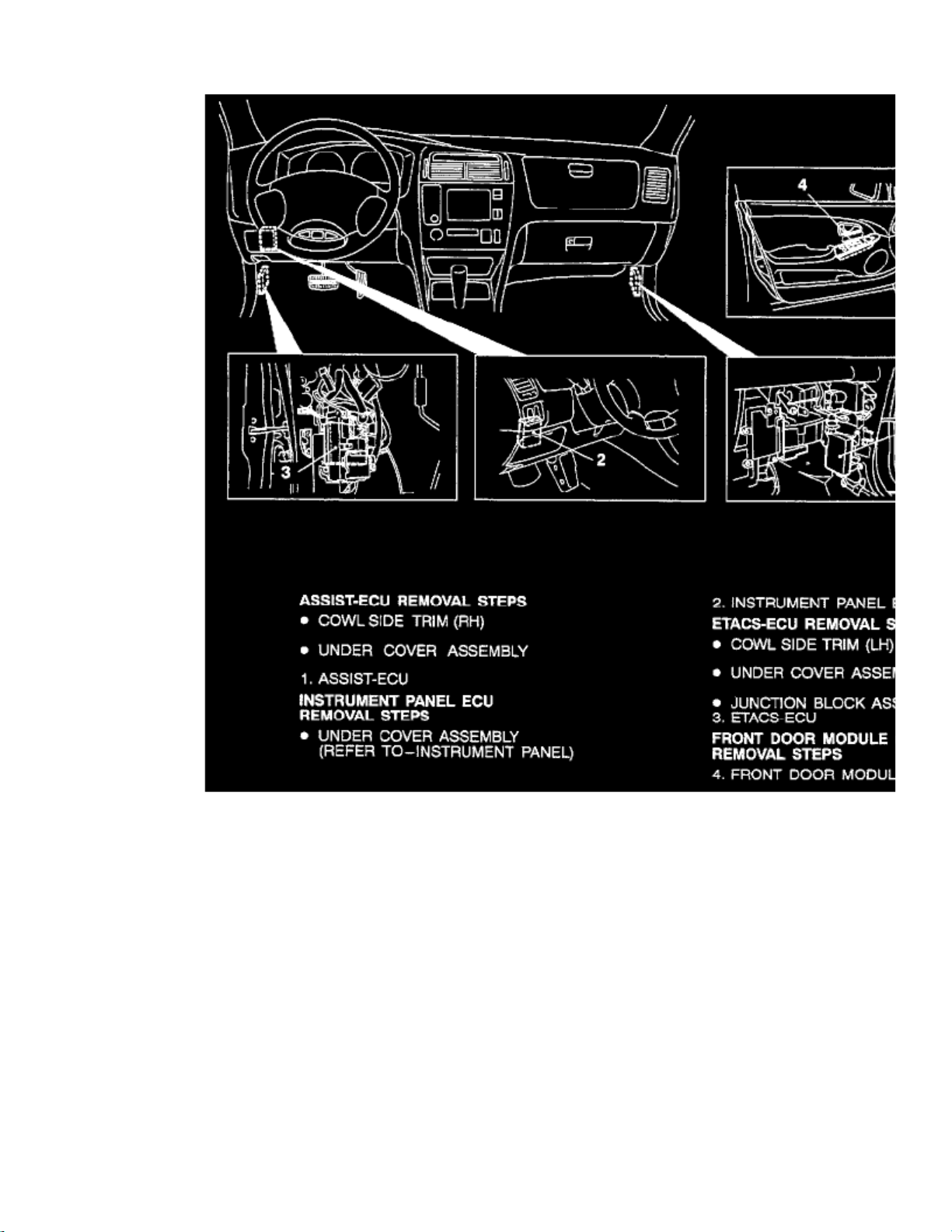
Door Module: Locations
Overall View
View F
Page 17

Page 18

> Relays and Modules > Relays and Modules - Body and Frame > Door Module > Component Information > Locations > Page 21
Page 19

Page 20

> Relays and Modules > Relays and Modules - Body and Frame > Fuel Door Release Relay > Component Information > Locations
Fuel Door Release Relay: Locations
Overall View
View G
Page 21

Page 22

> Relays and Modules > Relays and Modules - Body and Frame > Fuel Door Release Relay > Component Information > Locations > Page 25
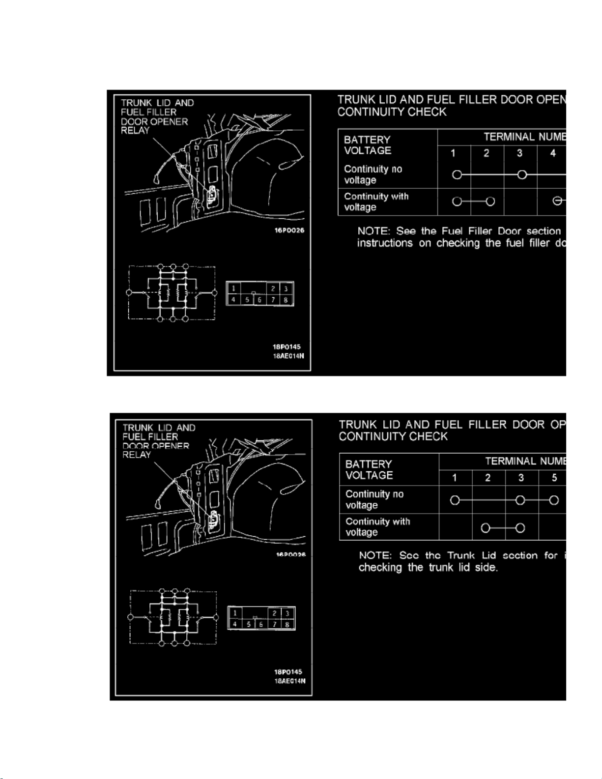
Fuel Door Release Relay: Testing and Inspection
Trunk Lid And Fuel Filler Door Opener Relay Continuity Check
Trunk Lid And Fuel Filler Door Opener Relay Continuity Check
Page 23

Page 24

> Relays and Modules > Relays and Modules - Body and Frame > Keyless Entry Module > Component Information > Testing and Inspection
Keyless Entry Module: Testing and Inspection
ETACS-ECU (KEYLESS ENTRY) TERMINAL VOLTAGE CHECK
Connector Terminal No 1 - 53
Page 25

> Relays and Modules > Relays and Modules - Body and Frame > Keyless Entry Module > Component Information > Testing and Inspection > Page 29
Diamante LS Sedan V6-3.5L SOHC (1998)
PART 1 OF 2
Page 26

Connector Terminal No 55 - 66
PART 2 OF2
For ETACS-ECU code related diagnosis refer to: Computers and Control Systems, Information Bus, Testing and Inspection.NOTE:
Page 27

Page 28
> Relays and Modules > Relays and Modules - Body and Frame > Keyless Entry Module > Component Information > Testing and Inspection > Page 30
Page 29

Page 30

> Relays and Modules > Relays and Modules - Body and Frame > Keyless Entry Module > Component Information > Testing and Inspection > Page 31
Page 31

Page 32

> Relays and Modules > Relays and Modules - Body and Frame > Power Mirror Control Module > Component Information > Description and Operation
Power Mirror Control Module: Description and Operation
-
When the remote-controlled mirror switch is operated while the ignition key is in "ACC" or "ON" position, the front door module (LH) determinesoperator requirements according to switch output signals.The front door module (LH) positions the LH door mirror by driving the mirror motors or sends a signal to the assist-ECU via the SWScommunication line.The assist-ECU drives the RH door mirror motors to position the mirror according to the signal received.
Page 33

Page 34

> Relays and Modules > Relays and Modules - Body and Frame > Power Seat Control Module > Component Information > Locations
Power Seat Control Module: Locations
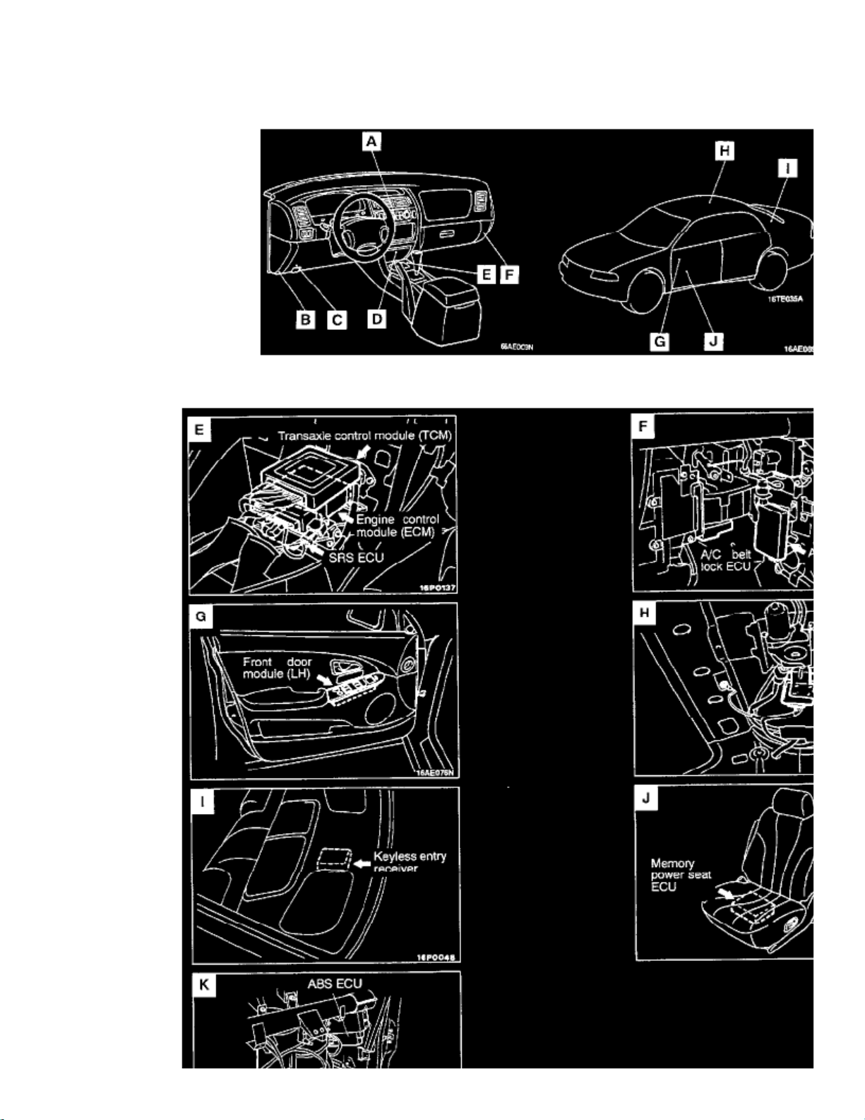
Control Unit Locations Overall View
Page 35

Control Unit Location Views E - J
Component View
Memory power seat ECU J
Page 36

> Relays and Modules > Relays and Modules - Body and Frame > Power Seat Control Module > Component Information > Locations > Page 38
Power Seat Control Module: Testing and Inspection
MEMORY POWER SEAT ECU TERMINAL VOLTAGE CHECK
Page 37

> Relays and Modules > Relays and Modules - Body and Frame > Power Seat Control Module > Component Information > Locations > Page 39
Diamante LS Sedan V6-3.5L SOHC (1998)
Connector Terminal No. 2 - 43
PART 1 OF 3
Page 38

Page 39

> Relays and Modules > Relays and Modules - Body and Frame > Power Seat Control Module > Component Information > Locations > Page 40
Diamante LS Sedan V6-3.5L SOHC (1998)
Connector Terminal No. 44 - 74
PART 2 OF 3
Page 40

Connector Terminal No. 75 - 76
PART 3 OF 3
For Memory Power Seat ECU code related diagnosis refer to: Computers and Control Systems, Information Bus, Testing and Inspection.NOTE:
Page 41

Page 42

> Relays and Modules > Relays and Modules - Body and Frame > Sunroof / Moonroof Module > Component Information > Locations
Sunroof / Moonroof Module: Locations
Overall View
View C
Page 43

Page 44

> Relays and Modules > Relays and Modules - Body and Frame > Trunk / Liftgate Relay > Component Information > Locations
Trunk / Liftgate Relay: Locations
Overall View
View G
Page 45

Page 46
> Relays and Modules > Relays and Modules - Body and Frame > Trunk / Liftgate Relay > Component Information > Locations > Page 47
Trunk / Liftgate Relay: Testing and Inspection
Trunk Lid And Fuel Filler Door Opener Relay Continuity Check
Trunk Lid And Fuel Filler Door Opener Relay Continuity Check
Page 47

Page 48

> Relays and Modules > Relays and Modules - Brakes and Traction Control > Brake Fluid Pump Relay > Component Information > Locations
Brake Fluid Pump Relay: Locations
Relay Locations Overall View
Page 49

> Relays and Modules > Relays and Modules - Brakes and Traction Control > Brake Fluid Pump Relay > Component Information > Locations > Page 52
Diamante LS Sedan V6-3.5L SOHC (1998)
Page 50

Page 51

Relay Location Views A - H
Page 52

> Relays and Modules > Relays and Modules - Brakes and Traction Control > Brake Fluid Pump Relay > Component Information > Locations > Page 53
Brake Fluid Pump Relay: Testing and Inspection
Page 53

Page 54

> Relays and Modules > Relays and Modules - Brakes and Traction Control > Brake Fluid Solenoid Valve Relay > Component Information > Locations
Brake Fluid Solenoid Valve Relay: Locations
Relay Locations Overall View
Page 55

> Relays and Modules > Relays and Modules - Brakes and Traction Control > Brake Fluid Solenoid Valve Relay > Component Information > Locations > Page 57
Diamante LS Sedan V6-3.5L SOHC (1998)
Page 56

Page 57

Relay Location Views A - H
Page 58

> Relays and Modules > Relays and Modules - Brakes and Traction Control > Brake Fluid Solenoid Valve Relay > Component Information > Locations > Page 58
Brake Fluid Solenoid Valve Relay: Testing and Inspection
Page 59

Page 60
> Relays and Modules > Relays and Modules - Brakes and Traction Control > Electronic Brake Control Module > Component Information > Locations
Electronic Brake Control Module: Locations
Control Unit Locations Overall View
Page 61

Control Unit Location Views E - J
Component View
ABS ECU K
Page 62

> Relays and Modules > Relays and Modules - Brakes and Traction Control > Electronic Brake Control Module > Component Information > Locations > Page 62
Electronic Brake Control Module: Testing and Inspection
CHECK AT THE ABS-ECU
Terminal Voltage Check Chart
1. Turn the ignition switch to OFF.2. Disconnect the ABS-ECU connector.
3. Measure the voltage at the terminals of the ABS-ECU harness-side connector while referring to the check chart.
NOTE:
Page 63

> Relays and Modules > Relays and Modules - Brakes and Traction Control > Electronic Brake Control Module > Component Information > Locations > Page 63
Diamante LS Sedan V6-3.5L SOHC (1998)
1. When measuring voltage, a harness for checking contact pin pressure should be! used instead of inserting a test probe.2. Checks do not have to be carried out in the order given in this chart.
CAUTION:
Short-circuiting the positive (+) probe between a connector terminal and ground could damage the vehicle wiring, the sensor,ABS-ECU, or all three. Use care to prevent this!
4. If voltmeter shows any deviation from standard value, check the corresponding sensor, actuator and related electrical wiring, then repair or
replace.
5. After repair or replacement, recheck with the voltmeter to confirm that the repair has corrected the problem.
Terminal Resistance And Continuity Checks
1. Turn the ignition switch to OFF.2. Disconnect the ABS-ECU connector.
Page 64

3. Measure the resistance and check for continuity between the terminals of the ABS-ECU harness-side connector while referring to the check
chart.
NOTE:
1. When measuring resistance and checking continuity, a harness for checking contact pin pressure should be used instead of inserting a test
probe.
2. Checks do not have to be carried out in the order given in this chart.
CAUTION:
If resistance or continuity checks are performed on the wrong terminals, damage to the vehicle wiring, sensors, ABS-ECU,and/or ohmmeter may occur. Use care to prevent this!
4. If ohmmeter shows any deviation from the normal condition, check the corresponding sensor, actuator and related electrical wiring, then repair
or replace.
5. After repair or replacement, recheck with the ohmmeter to confirm that the repair or replacement has corrected the problem.
Page 65

Page 66

> Relays and Modules > Relays and Modules - Brakes and Traction Control > Electronic Brake Control Module > Component Information > Locations > Page 64
Electronic Brake Control Module: Service and Repair
REMOVAL
Pre-removal Operation: -
Under Cover and Glovebox removal.
Follow removal steps outlined in illustration.
INSPECTION
Terminal Voltage Check Chart
1. Turn the ignition switch to OFF.2. Disconnect the ABS-ECU connector.
Page 67

> Relays and Modules > Relays and Modules - Brakes and Traction Control > Electronic Brake Control Module > Component Information > Locations > Page 65
Diamante LS Sedan V6-3.5L SOHC (1998)
Page 68

3. Measure the voltage at the terminals of the ABS-ECU harness-side connector while referring to the check chart.
NOTE:
1. When measuring voltage, a harness for checking contact pin pressure should be! used instead of inserting a test probe.2. Checks do not have to be carried out in the order given in this chart.
CAUTION:
Short-circuiting the positive (+) probe between a connector terminal and ground could damage the vehicle wiring, the sensor,ABS-ECU, or all three. Use care to prevent this!
4. If voltmeter shows any deviation from standard value, check the corresponding sensor, actuator and related electrical wiring, then repair or
Page 69

> Relays and Modules > Relays and Modules - Brakes and Traction Control > Electronic Brake Control Module > Component Information > Locations > Page 66
Diamante LS Sedan V6-3.5L SOHC (1998)
replace.
5. After repair or replacement, recheck with the voltmeter to confirm that the repair has corrected the problem.
Terminal Resistance And Continuity Checks
1. Turn the ignition switch to OFF.2. Disconnect the ABS-ECU connector.
Page 70

3. Measure the resistance and check for continuity between the terminals of the ABS-ECU harness-side connector while referring to the check
chart.
NOTE:
1. When measuring resistance and checking continuity, a harness for checking contact pin pressure should be used instead of inserting a test
probe.
2. Checks do not have to be carried out in the order given in this chart.
CAUTION:
If resistance or continuity checks are performed on the wrong terminals, damage to the vehicle wiring, sensors, ABS-ECU,and/or ohmmeter may occur. Use care to prevent this!
4. If ohmmeter shows any deviation from the normal condition, check the corresponding sensor, actuator and related electrical wiring, then repair
or replace.
5. After repair or replacement, recheck with the ohmmeter to confirm that the repair or replacement has corrected the problem.
INSTALLATION
Installation in reverse order as removal.
Post-installation Operation:-
Under Cover and Glovebox installation.
Page 71

Page 72

> Relays and Modules > Relays and Modules - Cooling System > Radiator Cooling Fan Motor Relay > Component Information > Locations
Radiator Cooling Fan Motor Relay: Locations
Relay Locations Overall View
Page 73

> Relays and Modules > Relays and Modules - Cooling System > Radiator Cooling Fan Motor Relay > Component Information > Locations > Page 71
Diamante LS Sedan V6-3.5L SOHC (1998)
Page 74

Page 75

Relay Location Views A - H
Relay View
Radiator fan relay (HI), (LO) & (MI) C
Page 76
> Relays and Modules > Relays and Modules - Cruise Control > Cruise Control Module > Component Information > Locations
Cruise Control Module: Locations
Control Unit Locations Overall View
Control Unit Location Views A - D
Component View
Auto cruise ECU D
Page 77

Page 78

> Relays and Modules > Relays and Modules - HVAC > Blower Motor Relay > Component Information > Locations
Blower Motor Relay: Locations
Relay Locations Overall View
Page 79

> Relays and Modules > Relays and Modules - HVAC > Blower Motor Relay > Component Information > Locations > Page 80
Diamante LS Sedan V6-3.5L SOHC (1998)
Page 80

Page 81

Relay Location Views A - H
Page 82

> Relays and Modules > Relays and Modules - HVAC > Blower Motor Relay > Component Information > Locations > Page 81
Blower Motor Relay: Testing and Inspection
Page 83

Page 84

> Relays and Modules > Relays and Modules - HVAC > Blower Motor Relay > Component Information > Locations > Page 82
Page 85

Page 86

> Relays and Modules > Relays and Modules - HVAC > Compressor Clutch Relay > Component Information > Locations
Compressor Clutch Relay: Locations
Relay Locations Overall View
Page 87

> Relays and Modules > Relays and Modules - HVAC > Compressor Clutch Relay > Component Information > Locations > Page 86
Diamante LS Sedan V6-3.5L SOHC (1998)
Page 88

Page 89

Relay Location Views A - H
Relay View
A/C compressor relay C
Page 90

> Relays and Modules > Relays and Modules - HVAC > Condenser Fan Motor Relay, HVAC > Component Information > Locations
Condenser Fan Motor Relay: Locations
Relay Locations Overall View
Page 91

> Relays and Modules > Relays and Modules - HVAC > Condenser Fan Motor Relay, HVAC > Component Information > Locations > Page 90
Diamante LS Sedan V6-3.5L SOHC (1998)
Page 92

Page 93

Relay Location Views A - H
Relay View
Condenser fan relay (HI) C
Condenser fan relay (LO) C
Page 94

> Relays and Modules > Relays and Modules - HVAC > Condenser Fan Motor Relay, HVAC > Component Information > Locations > Page 91
Condenser Fan Motor Relay: Testing and Inspection
Page 95

Page 96

> Relays and Modules > Relays and Modules - HVAC > Control Module HVAC > Component Information > Locations > Compressor Control Module
Control Module HVAC: LocationsCompressor Control Module
Control Unit Locations Overall View
Page 97

> Relays and Modules > Relays and Modules - HVAC > Control Module HVAC > Component Information > Locations > Compressor Control Module > Page 96
Diamante LS Sedan V6-3.5L SOHC (1998)
Control Unit Location Views E - J
Component View
Page 98

A/C belt lock ECU F
Page 99

Page 100

> Relays and Modules > Relays and Modules - HVAC > Control Module HVAC > Component Information > Locations > Compressor Control Module > Page 97
Control Module HVAC: LocationsElectronic Climate Control Module
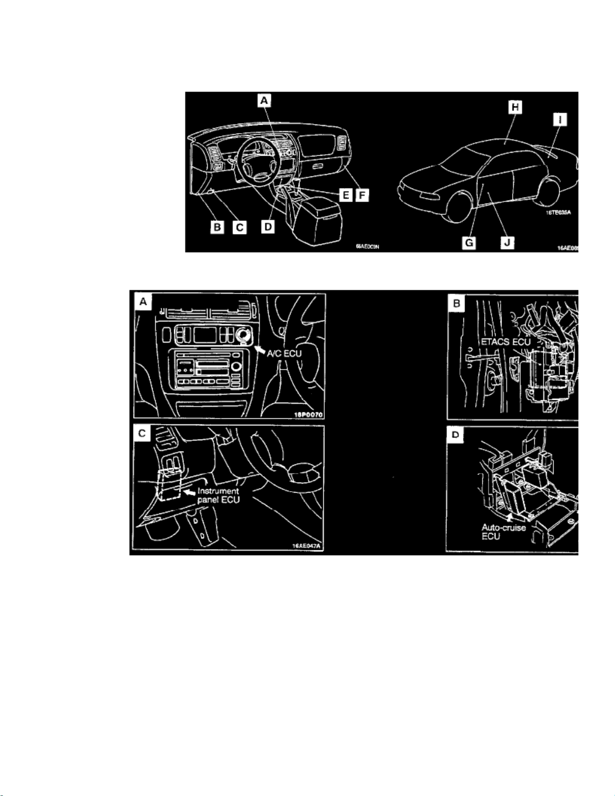
Control Unit Locations Overall View
Control Unit Location Views A - D
Component View
A/C ECU A
 Loading...