


BACKUP
Service Manual
ENGINE
1992
-
1993
FOREWORD
The information contained in this service manual
has been prepared for the professional automotive
technician involved in daily repair operations. Information in this manual is divided into groups by
engine models. Each group is further divided to
address individual components within the group.
These groups contain general information, specification, removal and installation, disassembly and
reassembly procedures for the components. The
first page of each group contains an alphabetical
index to assist in finding the location of the
component. The information, descriptions and specifications were in effect at the time this manual
was released.
GROUP INDEX
Introduction
Engine
4Gl
463
466 <1992>
. . . . . . . . . . . . . . . . . . . . . . . . . . . . . . . . . . . . . . . .
. . . . . . . . . . . . . . . , . . . . . . . . . . . . . . . . . . . . . . . .
. . . . . . . . . . . . . . . . . . . . . . . . . . . .
mm
. . . . . . . . . . . . . . . . . . . . . . . .
mm
This
BACKUP DSM manual IS to be used ONLY as a BACKUP. Please DO NOT REDISTRIBUTE
WHOLE SECTIONS.
a GENUINE DSM MANUAL. It CANNOT BE considered a REPLACEMENT (Unless your original
manual was lost or destroyed.)
Please See
Mitsubishi Motors Co[poration reserves the right to make changes
dew?
or to make addltlons to or improvements in its products
impoang
previously manufactured.
This
BACKUP was sold to you under the fact that you do
README.N
any obligations upon itself to install them on its products
or
READMEHTML
Thank you. G~mm~emymanual@hotma~l.com
VOLUNTARY TECHNICIAN
CERTIFICATION THROUGH
for
additional Information.
WE SUPPORT
National
lnstit~te
AUTOMOTIVE
SERVICE
EXCELLENCE
for
indeed
OWN
WIthout
469
6G7
4G6 <1993>
in
. . . . . . . . . . . . . . . . . . . . . . . . . . . . . . . . . . ...*..
m
. . . . . . . . . . . . . . . . . . . . . . . . . . . . . . . . . . . . . . . .
. . . . . . . . . . . . . . . . . . . . . . . .
CCT
@ qgg2
M&ubi&i Motors Corporation
Printed in Japan


INTRODUCTION
CONTENTS
:,
ENGINE MODEL TABLE
EXPLANATION OF MANUAL CONTENTS
FORM-IN-PLACE GASKET
Disassembly
Form-In-Place Gasket Application
Surface
Preparation
. . . . . . . . . . . . . . . . . . . . . . . . . . . . . . . . . . . . . . . . . . . . . . . . . . . . . . . .
. . . . . . . . . . . . . . . . . . . . . . . . . . . . . . . . . . . . . . . .
. . . . . . . . . . . . . . . . . ..I................
._......................
. . . . . . . . . . . . . . . . . . . . . . . . . . . . . . . . . . . . . . . . . . . .
4
. . . . . . . .
2
6
6
6
6
SPECIAL TOOL NOTE
TORQUE REFERENCES
. . . . . . . . . . . . . . .
. . . . . . . . . . . . . . . . . . . . . . . . . . . . .
. . . . . . . . . . . . . . . . . . . . . . . . . . . . . . . . ..I.....
1.
:
._
.
5
5
,
‘-:
:

2
INTRODUCTION
EXPLANATION OF MANUAL CONTENTS
0
Maintenance and Servicing Procedures
(1) A diagram of the component parts is
provided near the front of each section in
order to give the reader a better under-
standing of the installed condition of
component parts.
(2) The numbers provided within the diagram
indicate the sequence for maintenance
and servicing procedures; the symbol
indicates a non-reusable part; the tighten-
ing torque is provided where applicable.
m
Removal steps:
l Disassembly steps:
0
Installation steps:
l Reassembly steps:
I
The part designation number corresponds
to the number in the illustration to indicate
removal steps.
The part designation number corresponds
to the number in the illustration to indicate
disassembly steps.
Specified in case installation is impossible
in reverse order of removal steps. Omitted if installation is possible in reverse
order of removal steps.
Specified in case reassembly is
ble
in reverse order of disassembly
Omitted if reassembly is possible
verse order of disassembly steps.
ia
im$ossi-
Classification of Major Maintenance/
Service Points
When there are major points relative to maintenance and servicing procedures (such as essential
maintenance and service points, maintenance and
service standard values, information regarding the
use of special tools, etc.), these are arranged
together as major maintenance and service points
and explained in detail.
GAO:
Indicates that there are essential points for
removal or disassembly.
I)A4:
Indicates that there are essential points for
installation or reassembly.
Symbols for Lubrication, Sealants and
Adhesives
Information concerning the locations for
tion and for application of sealants and adhesives
is provided, by using symbols, in the diagram of
component parts, or on the page following the
component parts page, and explained.
lubrica-
&
. . Grease
(multrpurpose grease unless there is
a brand or type specified)
. . . . .
Sealant or adhesive
. . . . .
i
:m
Brake fluid, automatic transmission
fllid
or air conditioning compressor
. . . . . Engine oil or gear oil
I
TSB Revision

INTRODUCTION
Indicates the
section title.
3
Denotes non-reusable
This number corresponds to the
number appearing in “Removal
steps”, “Disassembly steps”,
stallation steps” or “Reassembly
steps”
Operating procedures, cautions,
etc. on removal, installation, disassembly and reassembly are described.
“ln-
I
I
TSB Revision

4
ENGINE MODEL TABLE - 1992
Engine
Series,
4Gl
4G3
4G6
INTRODUCTION
4G9
6G7
4693
6672
6G72 3.0 (183)
6G72
Turbo
1.8
(1
IO)
3.0(I83)
3.0 (183)
ENGINE MODEL TABLE - 1993
In-line,
6O”V.
SOHC
6O”V.
DOHC
6O“V.
DOHC
SOHC
(per bank)
(per bank)
(per bank)
E$po
LRV
bgmante,
h&ntero,
Diamante, 3000GT
4 3000GT
.K
c:
Truck
4G9
6G7
4664
4G93
6672
6672
6G72
Turbo
.
2.4(146)
1.8 (1
IO)
3.0 (I 83)
3.0 (183)
3.0 (183)
1
TSB Revision
In-line, SOHC
In-line, SOHC
6O”V.
SOHC
(per bank)
6O”V,
DOHC 4
(per bank)
6O”V.
DOHC
(per bank)
4
4
2
4
E$po-LRV.
@age,
Diamante,
Mhtero,
C$mante,
3600GT
Expo LRV
Expo
Truck
3000GT

SPECIAL TOOL NOTE
INTRODUCTION
.
1
6
Please refer to the special tool cross reference chart which is located in the service manual at the beginning of
each group, for a cross reference from the MMC special tool number to the special tool number that is
available in your market.
iiS *‘l
*.j,
l”
“...!: ‘/’
TORQUE REFERENCES
General tightening torque is as shown in the following table.
The specific part tightening torque is shown at the beginning of each group.
Flange bolt
Heaid.
i-MC 7
ft.lbS.
Size mm
(dia. x pitch)
5 x 0.8
6x
1.0
8 x 1.25
10x1.25
12x
1.25
14x1.5
Bolt with spring washer
Head mark 4 Head mark 7 Head mark 10 Head mark 4
Nm
ft.lbs. Nm ft.lbs. Nm ft.lbs. Nm ft.lbs. Nm
NEW TIGHTENING METHOD - BY USE OF BOLTS TO BE TIGHTENED IN PLASTIC AREA
A new type of bolts, to be tightened in plastic area, is currently used in
tightening method for the bolts is different from the conventional one. Be sure to observe the
so’me
parts of the engine. The
method
described in the text when tightening the bolts.
Service limits are provided for the bolts. Make sure that the service limits described in the text are strictly
observed.
l Areas where the bolts are in use:
(1) Cylinder head bolts
(2)
Main bearing cap bolts
(3) Connecting rod cap bolts
Remarks:
The bolts in
The bolts in (3) apply to the
l Tightening Method
After tightening the bolts to the specified torque, tighten them another
(1)
and (2) apply to the
4G15, 4G6 <1993>
4G6 <I 993>
and
and
4G93
4693
engines.
engines.
90”
or 180” (twice 90”). The
tightening method varies on different areas. Observe the tightening method described in the text.
TSB Revision

INTRODUCTION
FORM-IN-PLACE GASKET
The engine has several areas where the form-in-place gasket
serves its purpose, it is necessary to observe some precautions when applying the gasket. Bead size,
continuity and location are of paramount importance. Too thin a bead could cause leaks. Too thick a bead, on
the other hand, could be squeezed out of location, causing blocking or narrowing of the fluid feed line. To
eliminate the possibility of leaks from a joint, therefore, it is absolutely necessary to apply the gasket evenly
without a break, while observing the correct bead size.
The
FIPG
used in the engine is a room temperature vulcanization (Rn/) type and is supplied in a loo-gram
tube (Part No. MD970389 or
atmospheric air, it is normally used in the metallic flange areas. The FIPG, Part No.
for sealing both engine oil and coolant, while Part No. 997110 can only be used for engine oil sealing.
Disassembly
The parts assembled with the
cases, however, the sealant between the joined surfaces may have to be broken
mallet or similar tool. A flat gasket scraper may be lightly hammered in between the joined surfaces. In this
case, however, care must be taken to prevent damage to the joined surfaces.
MD9971 10).
FIPG
can be easily disassembled without use of a special method. In some
Since the
RTV
(FIPG)
is in use. To ensure that the gasket fully
hardens as it reacts with the moisture in the
MD970389,
bylightly
can be used
striking with a
Surface
Thoroughly remove all substances deposited on the gasket application surfaces, using a gasket scraper or
wire brush. Check to ensure that the surfaces to which the
are no oils, greases and foreign substances deposited on the application surfaces. Do:not forget to remove
the old sealant remaining in the bolt holes.
Form-In-Place Gasket Application
When assembling parts with the FIPG, you must observe some precautions, but the procedure is very simple
as in the case of a conventional precut gasket.
Applied
circumference with a completely continuous bead. The
the
make sure that the gasket is applied to the required area only.
The
when applying the FIPG.
Preparation
FIPG
is to be applied is flat.‘ Make sure that there
5
FIPG
bead should be of the specified size and without breaks. Also be sure
FIPG
can be wiped away unless it is hardened. While
FIPG
is still moist (in less than 15 minutes), mount the parts in position. When the parts are mounted,
FIPG
application procedure may vary on different areas. Observe the procedure described in the text
toencircle
the bolt hole
TSB Revision

4G15
CONTENTS
BRACKET
CRANKSHAFT, FLYWHEEL AND
DRIVE PLATE
CYLINDER HEAD AND VALVES
EXHAUST MANIFOLD AND
WATER PUMP
FRONT CASE AND OIL PUMP
FUEL AND EMISSION PARTS
GENERAL INFORMATION
GENERAL SPECIFICATIONS
GENERATOR AND IGNITION SYSTEM
................................................................
........................................................
........................
....................................................
............................
............................
................................
............................
........
53
51
33
28
39
22
14
INTAKE
PISTON AND CONNECTING ROD
ROCKER ARMS AND CAMSHAFT
SEALANT
SERVICE SPECIFICATIONS
SPECIAL TOOLS
THROlTLE
TIMING
2
TORQUE SPECIFICATIONS
5
MANIFOLD
................................................................
BODY
BELT
............................................
....................
....................
................................
....................................................
................................................
........................................................
................................
26
43
30
11
6
12
24
17
10

IlA-2
4Gl
ENGINE - General Information
GENERAL INFQRMATION
ENGINE SECTIONAL VIEW
TSB Revision
3
1
EN0086

4Gl
ENGINE
-
General Information
TSB Revision
1

VA-4
4Gl
ENGINE - General Information
UBRICATION
SYSTEM
0’
t7;
ii
I
P
‘Z
:
ii
OTJ
09
1
TSB Revision

4Gl
ENGINE - General Specifications
GENERAL SPECIFICATIONS
Items
We
Number of cylinders
Combustion chamber
Total displacement
Cylinder bore
Piston stroke
Compression ratio
Valve timing
(): Camshaft identification mark
Intake valve
Opens
Closes
Exhaust valve
Opens
Closes
Lubrication system
Oil pump type
Cooling system
Water pump type
EGR valve
Injector type and number
Injector identification No.
Fuel regulated pressure kpa (psi)
Throttle bore mm (in.)
Throttle position sensor
Closed throttle position switch
Y’
1: up to 1992 models
“2:
From 1993 models
.---
cm3 (cu.in.)
mm (in.)
mm (in.)
BTDC
ABDC
BBDC
ATDC
Specifications
In-line OHV, SOHC
4
Pentroof
1,468 (89.58)
75.5 (2.972)
82 (3.228)
9.2
(1 I*’
14”
51” 53”
51” 57”
14”
Pressure feed, full-flow filtration
Trochoid type
Water-cooled forced circulation
Centrifugal impeller type
Single type
Electromagnetic, 4
BDH182
335 (47.6)
46(1.811)
dariable
Contact type, within idle speed control
Movable contact type within throttle position sensor*’
type
(6)**
15”
15”
resistor type
motor”
1
TSB Revision
I

1
IA-6
4Gl
ENGINE - Service Specifications
SERVICE SPECIFICATIONS
Items
Cylinder head
Flatness of gasket surface
Grinding limit of gasket surface
t
Total resurfacing depth of both cylinder
head and cylinder block
Overall height
Oversize rework dimensions of valve guide hole
(both intake and exhaust)
0.05
(.002)
0.25(.010)
0.50
(.020)
Oversize rework dimensions of intake valve
seat ring hole (primary)
0.3
(.012)
0.6(.024)
Oversize rework dimensions of intake valve
seat ring hole (secondary)
0.3
(.012)
0.6
(.024)
Oversize rework dimensions of exhaust valve
seat ring hole
0.3
(.012)
0.6
(.024)
Camshaft
Cam height
Intake
Exhaust 39.10 (1.5394)
Journal diameter
3il
clearance
Standard value
d.05 (.0020)
106.9-107.1 (4.209-4.217)
12.05-12.07 (.4744-.4752)
12.25-
12.27
12.50-12.52 (.4921 -.4929)
27.42-27.44(1.0795-1.0803)
27.72-27.74(1.0913-1.0922)
32.43-32.45
32.73-32.75
35.43-35.45(1.3949-1.3957)
35.73-35.75(1.4067-1.4075)
38.78 (1.5268)
45.93-45.94(1.8083-1.8087)
0.06-0.10(.0024-.0039)
(.4823-.4831)
(1.2768-1.2776)
(1.2886-1.2894)
“”
Limit
0.2(.008)
"0.2
3
1
“1
'$
1,
I)
1
1:
!
(.008)
38.28
38.60(1.5197)
mm (in.)
(1.5071)
qockerarm
.D.
3ocker
arm-to-shaft clearance
qockerarmshaft
I.D.
3verall
length
Intake
Exhaust
TSB Revision
18.91
-18.93(.7445-.7453)
0.01
-0.04(.0004-.0016)
18.89-18.90(.7437-.7441)
365(14.37)
346(13.62)
0.1
(.004)

Items
Valve
Overall length
Intake
Exhaust
Stem diameter
Intake
Exhaust
Face angle
Thickness of valve head (margin)
Intake
Exhaust
Stem-to-guide clearance
Intake
Exhaust
Valve clearance
Intake
Exhaust
4Gl
ENGINE - Service Specifications
Standard value
100.75 (3.9665)
101.05 (3.9783)
6.57 - 6.58
6.53 - 6.55
(2587 - .2591)
(2571 - .2579)
45” - 45”30’
1 .o
(.039)
1.5
l.059)
0.02 - 0.05
0.05 - 0.09
0.07
0.09
(0008 - .0020)
(.0020 - .0035)
(.0028)
Up to 1992 models
(.0035)
From 1993 models
0.17 (0067)
Limit
0.5
(020)
1 .o (.039)
0.10
(.0039)
0.15
(.OOSS)
mm (in.)
.,_ ..“.. ..“_
.
.
1 t..
,-i
,
-7, ,i ,,- <
i
7/
Valve spring
Free height
Intake
Exhaust
-oad/installed
height
Intake
Exhaust
3ut-of-squareness
halve
guide
3verall
length
Intake
Exhaust
.D.
I.D.
;ervice size
‘Tess-in
lalve
;eat
lalve
temperature
seat
angle
contact width
Gnkage
iervice size
N/mm
(Ibs./in.)
46.1 (1.815)
46.8 (1.843)
230/40
(51/I
.57)
290140
(64/l
.57)
Max. 2”
44 ( 1.732)
49.5 (1.949)
6.60 - 6.62
12.055 - 12.065
0.05
(.002),
(.2598 - .2606)
(4746 - .4750)
0.25
(.Ol).
Room temperature
43”30’ - 44”
0.9 - 1.3
0.3
LO1 2),
(035 - .051)
0.6
(024)
0.50 (02) oversize
oversize
45.1 (1.776)
45.8 (1.803)
4”
0.2
(.008)
. .
\-TSR
Revision
I

IIA-8
4Gl
ENGINE - Service Specifications
mm (in.)
Items
Piston
O.D.
Piston-to-cylinder clearance
Service size
Piston ring
End gap
No. 1 ring
No. 2 ring
Oil ring
Ring-to-ring groove clearance
No. 1 ring
No. 2 ring
Service size
Piston pin
O.D.
Press-in load N (psi)
Press-in temperature
Standard value
75.48 - 75.50 (2.9716 - 2.9724)
0.02 - 0.04
0.25
oversize
0.20 - 0.40 l.0079 -
0.20 - 0.35
0.20 - 0.70
0.03 - 0.07
0.02 - 0.06 f.0008 -
0.25
(.Ol),
oversize
18.003 -
5,000 - 15,000 (1 ,102 - 3,307)
Room temperature
(0008 - .0016)
t.01).
0.50
(.02),
(.0079 - .0138)
LOO79 - .0276)
(.0012 - .0028)
0.50
(.02),
18.005 l.7088 -
0.75
.0157)
.0024)
0.75
(.03),
(.03),
.7089)
1
1
.OO
.OO
(.04)
(04)
Limit
0.8
(.031)
0.8
f.031)
1 .o i.039)
0.1
(.004)
0.1 i.004)
Connecting rod
Big end center-to small end center length
Bend
Twist
Big end side clearance
Crankshaft
End play
Journal O.D.
Pin O.D.
Dut-of-roundness and taper of journal and pin
3il
clearance of journal
3il
clearance of pin
Cylinder
Ilatness
Grinding
3verall
block
.D.
of gasket surface
limit of gasket surface
Total resurfacing depth of both cylinder
block and cylinder head
height
130.95-
0.05
0.1
0.10 - 0.25
0.05-0.18 (.0020- .0071)
48 (1.89)
42 (1.65)
0.005 (.0002)
0.02 - 0.05
0.02 - 0.05
75.50 - 75.53 (2.9724 - 2.9736)
0.05 i.002)
255.9 - 256.1
131.05 (5.1555-5.1594)
(.0020)
(.004)
(.0039 - .0098)
(.0008 - .0020)
(.0008 - .0020)
(10.075 - 10.083)
0.4
f.016)
0.3
(.012)
0.1 i.004)
0.1
(.004)
0.1 i.004)
*0.2
(.008)
TSB
Revision

Items
Oil
pump
Tip clearance
Side clearance
Body clearance
Drive belt deflection
New belt
Used belt
Injector
Coil resistance
Throttle position sensor
Resistance
Idle speed control motor
Coil resistance
Idle air control motor
Coil resistance
fI?
kR
rc1
0
4Gl
ENGINE - Service Specifications
Standard value
0.03 - 0.08
0.04-0.10(.0016-.0039)
O.lO-0.18(.0039-.0071)
5.5 -7.0
8.0
(.32)
13 - 16
3.5-6.5
5 - 35 at
28 - 33 at
LOOI
(.22 - .28)
at
20°C (68°F)
20°C (68°F)
20°C (68°F)
2 -
.0031)
Limit
0.35
rn:fq,
(in,
i ,I :, i /
.’
(.Orl38)
Idle speed control motor position sensor
Resistance
kfi
4-6
1
TSB Revision

1
IA-IO
4Gl
ENGINE - Torque Specifications
TORQUE SPECIFICATIONS
Generator and ignition system
Oil level gauge guide mounting bolt
Water pulley bolt
pump
Generator brace bolt
Generator brace mounting bolt
Generator pivot nut
Crankshaft bolt
Crankshaft pulley bolt
Spark plug
Distributor
Timing belt
Engine support bracket, left
Tensioner bolt
Camshaft sprocket bolt
Fuel and emission parts
Throttle body mounting bolts
Fuel rail mounting bolts
Fuel regulator bolts
pressure
EGR valve (California) mounting bolts
Nm
11
9
14
24
23
85
14
25
12
36
24
70
19
12
9
13
ftlbs.
-
8
7
10
17
17
61
10
18
9
i
ii 26
17
51
14
‘7
9
7
9
Throttle body
Throttle position sensor attaching bolts
Intake manifold
Cable bracket bolt
Engine coolant temperature gauge unit
Engine coolant temperature sensor
Therm0
flater
Thermostat housing bolt and nut
Intake manifold stay bolt
Engine support bracket stay
Intake manifold bolt and nut
Exhaust manifold and water pump
Exhaust manifold cover “A” bolt
Exhaust manifold cover “A” and
Exhaust manifold cover “B” bolt
Exhaust manifold nut
Vater inlet pipe bolt
Vater
Ixygen
switch
outlet fitting bolt
bolt
pump
sensor
“B”
mounting bolt
2.0
14
11
30
8
19
18
22
36
18
30
9
24
18
14
14
45
1.5
11
8
22
6
14
13
16
26
13
22
7
18
13
11
11
33
jocker
arms and camshaft
jocker cover bolt
locker arm shaft bolt
iocker arm lock nut
TSB Revision
1.8
32
15
1.3
24
11

461
ENGINE - Torque Specifications / Sealant
Cylinder head and valves
Cylinder head bolt
Front case and oil pump
pan
Oil drain plug
pan
Oil bolt
Oil screen bolt
Oil relief valve plug
Front case bolt
Oil pump cover screw
Piston and connecting rod
Connecting rod cap nut
Crankshaft, flywheel and drive plate
Flywheel and drive plate
Rear plate bolt
Bell housing cover bolt
Oil seal case bolt
Bearing cap bolt
3il switch
pressure
Nm
73
40
7
19
45
I4
IO
20 +
135
11
9
11
53
19
I/4
turns
ft.lbs.‘, I. ‘-,.‘.,;
53
29
5
14
33
11
8
14.5 +
98
8
7
8
38
14
l/4
turns
$8;
_.”.c
Bracket
Exhaust pipe support bracket
Engine support bracket, front
7011
stopper bracket, front
3011
stopper bracket, rear
SEALANT
Items
Therm0
Engine coolant temperature sensor
Engine coolant temperature gauge unit
Oil pan
Oil pressure switch threads
switch
36
60
65
120
Specified sealant
3M
Nut Locking part No. 4171 or equivalent
3M
Nut Locking part No. 4171 or equivalent
3M
ATD Part No. 8660 or equivalent
Mitsubishi Genuine Part No. MD970389 or equivalent
3M ATD Part No. 8660 or equivalent
26
43
47
87
Quantity
As required
As required
As required
As required
As required
TSB Revision

1
IA-12
SPECIAL TOOLS
Tool
4Gl
ENGINE - Special Tools
MD99801 1
Crankshaft rear
oil seal installer
Crankshaft front
oil seal installer
MD99871
Camshaft oil seal
3
MD99801 I-01
MD998713-01
Installation of crankshaft rear oil seal
Installation of camshaft oil seal
TSB Revision
Removal of oil pan
ompresslon 0
,.
i
.
.

4Gl
ENGINE - Special Tools
Valve stem seal
compressor
Flywheel stopper
1
TSB Revision

4Gl
1 IA-14
ENGINE - Generator and Ignition System
GENERATOR AND IGNITION SYSTEM
REMOVAL AND INSTALLATION
*
_,
12 Nm
9
ftJp3.
14 Nm
10 ft.lbs.
Ji
I
24Nr;l
17
ft.lbs.
9Nm
7
23 Nm
” Rm/b=-
I
n
\!
I
85 Nm
81
ft.lbs.
1
TSB Revision
1
Removal steps
1,
Oil level gauge
2. Oil level gauge guide
3. O-ring
+C4
4. Drive belt
5. Water pump pulley
6. Generator brace
7. Generator
(IA!) +B4
8. Crankshaft bolt
9. Special washer
IO. Crankshaft pulley
11. Damper pulley
12. Spark plug cable
13.
Spark
*A4 ‘ll.
;.s;;$butor
.
-
plug
1
EN0325

461
ENGINE
-
Generator and Ignition System
REMOVAL SERVICE POINT
OAo
CRANKSHAFT BOLT REMOVAL
(I) Using the special tool, hold the drive plate or flywheel.
(2) Remove the crankshaft bolt.
INSTALLATION SERVICE POINTS
r)A4
DISTRIBUTOR ASSEMBLY INSTALLATlOy
(1) Turn the crankshaft to bring the No. I cylinder piston to the
top dead center on compression stroke.
(2) Align the mating mark on
thedistributor
housing with that
on the coupling key.
/
1
EL004
(3) Install the distributor with the coupling key fitted in the
keyway at the end of the camshaft.
r)64
CRANKSHAFT BOLT INSTALLATION
(I) Using the special tool, hold the drive plate or flywheel.
(2) Install the crankshaft bolt.
1 EN0326
F
#c4
(I) Adjust the belt deflection with the adjusting bolt to the
1
EN029'
1
TSB Revision
DRIVE BELT TENSION ADJUSTMENT
standard value.
Standard value:
New belt
Used belt
5.5 - 7.0 mm
8.0 mm
(.32
in.)
(.22 - .28
in.)

4Gl
ENGINE - Generator and Ignition System
6EN059E
(2)
Or using a tension gauge, adjust the tension to the standard
value.
Standard value:
New belt 500
Used belt 400 N (88 Ibs.)
(3) Tighten the lock bolt to the specified torque.
(4) Tighten the nut for pivot bolt to th$ specified torque.
6EN0591
-
700
N (116 -
154
Ibs.)
1
TSB Revision
I
I

461
TIMING BELT
REMOVAL AND INSTALLATION
ENGINE - Timing Belt
2bnhll
17
ft.lbs.
d
7
8
I
Removal steps
1. Timing belt upper cover
2. Timing belt lower cover
@I$ eC4
OBO
$I$
3. Timing belt
4. Engine support bracket, left
5. Tensioner spring
+B4
6. Tensioner
7. Crankshaft sprocket
8. Flange
*A4
9. Camshaft sprocket bolt
10. Camshaft sprocket
TSB Revision
1
EN0327
I

461
ENGINE
-
Timing Belt
REMOVAL SERVICE POINTS
OAo
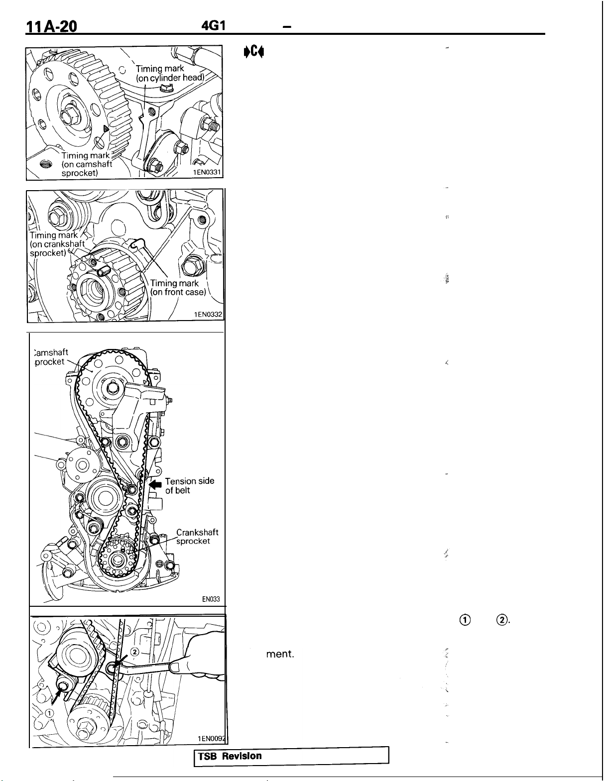
TIMING BELT REMOVAL
(1) Mark belt running direction for reference in reinstallation.
(2) Loosen the tensioner bolts and move the tensioner toward
the water pump.
(3) Remove the timing belt.
NOTE
(1)
Water or oil on the belt shortens its life drastically, so
the removed timing belt, sprocket, and tensioner must
be kept free from oil and water. Do not immerse parts in
cleaning solvent.
(2) If there is oil or water on any part, check the front case
oil seal, camshaft oil seal and
4Bo
CRANKSHAFT SPROCKET
~
wfter
pump for leaks.
,
REldOVAL
r-
@o
CAMSHAFT SPROCKET BOLT LOOSENING
INSPECTION
TIMING BELT
Replace belt if any of the following conditions exist.
(1) Hardening of back rubber side is glossy without resilience
and leaves no indent when pressed with fingernail.

461
ENGINE - Timing Belt
Peeling
Cracks
Roundededge
Abnormal wear
(Fluffy strand)
Rubber exposed
1
EN024E
8EN006;
Cracks on
(2)
Cracks or
(3)
Cracks on
(4)
(5) Cracks on
(6)
Abnormal wear of belt sides. The sides are normal if they
rubber back
peeling of canvas
rib root
belt sides
are sharp as if cut by a knife.
(7) Abnormal wear on teeth
(8) Missing tooth
Water
pump
Tooth missing
and canvas fiber
MIT308239
/
8EN006
I
01
PO281
INSTALLATION SERVICE
I)A4
CAMSHAFT SPROCKET BOLT TIGHTENING
I)B4
TENSIONER INSTALLATION
(I)
Move the tensioner pulley toward the water pump and
POIFTS
tighten the tensioner mounting bolts.
1 EN0003
TSB Revision
11
A-20
4Gl
ENGINE - Timing Belt
I)cg
TIMING BELT INSTALLATION
(1) Align the timing marks on the camshaft sprocket and the
crankshaft sprocket with their timing marks.
-
1
EN033
(2) Set the timing belt first on crankshaft sprocket and then
keeping the tension side belt tight, set on the camshaft
sprocket.
(3) Loosen the tensioner mounting bolts @ and
(4) Check that the belt completely meshes with the sprocket.
Also check the timing marks on the sprockets for align-
4
0.

4Gl
ENGINE - Timina Belt
\
Tensioner slot side
il
1
ENOOOE
(5) Turn the crankshaft clockwise by 3 crankshaft
teeth.
(6) Tighten bolt @ first and then bolt 0. If bolt @ is tightened
first, the tensioner will turn together with the bolt, resulting
in an overtensioned belt.
(7) Check the belt tension. Hold the tensioner and ‘timing belt
together by hand and give the belt a slight thumb pressure
at a point level with tensioner center. Make sure that belt
cog crest comes as deep as about
slot side tensioner bolt head.
l/4
of the width of the
s@Cxket
I
ll4of
bolt head
1
EN025
TSB
Revision

461
IIA-22
ENGINE - Fuel and Emission Parts
FUEL AND EMISSION PARTS
REMOVAL AND INSTALLATION
19 Nm
;;
14
ft.lbs.
TSB Revision
Removal steps
1.
Throttle body
2.
Gasket
3. Injectors and fuel rail
4.
eB4 ;.
*A4
*A4
Insulator
Fuw&ressure regulator
7:
Insulator
8. Injector clip
9.
Injector
10.
O-ring
11.
Grommet
12.
Fuel rail
13. EGR valve (For California)
14.
Gasket
1 EN0238
 Loading...