

Page 1

Body/equipment mounting directives
for CANTER EURO V (FB/FE)
Europe
'HFHPEHU 2010
Page 2

Mitsubishi Fuso Service
Body/equipment mounting directives
for Canter EURO V (FB/FE)
Europe
KAWASAKI, JAPAN
Page 3

Contents
10.Dec. 2010
1 Introduction
1.1 The aim of these directives 6
1.2 Conventions 8
1.3 Vehicle safety 9
1.4 Operational reliability 10
Accident prevention 11
1.5
2 General
2.1 Vehicle and model designations 12
2.2 Technical advice and contact persons 14
2.3 Issue of letter of no objection 15
2.4 Product safety 17
2.5 Mitsubishi three diamonds and Fuso emblem 19
2.6 Recycling of components 20
2.7 Quality system 21
3 Planning of bodies
3.1 Selecting the chassis 22
3.2 Vehicle modifications 23
3.3 Dimensions, weights, overall vehicle height 24
3.4 About vehicle body incline 28
3.5 Tyres 29
3.6 Bolted and welded connections 30
3.7 Soundproofing 32
3.8 Exhaust system 33
3.9 Maintenance and repairs 35
3.10 Special equipment 38
4 Technical threshold values for planning
4.1 Vehicle overhang and technical wheelbases 39
4.2 Weight distribution, CoG height, anti-roll bars 41
4.3 Steerability 42
4.4 Clearance for assemblies and cab 43
4.5 Wind deflectors 45
4.6 Governor and transmission power-take-off 48
Mitsubishi Fuso body/equipment mounting directives for Canter EURO V (FB/FE) Issue date: 27. Jan. 2010
! Only print out complete sections from the current versioni
2
Page 4

Contents
10.Dec. 2010
5 Damage prevention
5.1 Electrical system 55
5.2 Brake hoses/cables and lines 57
5.3 Mobile communications systems 58
5.4 Electromagnetic compatibility (EMC) 59
5.5 Welding work 60
5.6 Corrosion protection measures 62
5.7 Corrosion prevention in welding work 64
5.8 Bolted connections 65
5.9 Painting work 67
5.10 Leaf springs 68
5.11 Tilting the cab 69
5.12 Towing and tow-starting 70
5.13 Risk of fire 71
5.14 Storing and handing over the vehicle 72
6 Modifications to the basic vehicle
6.1 General 73
6.2 Chassis frame material 74
6.3 Drilling work on the vehicle frame 75
6.4 Welding work on the vehicle frame 77
6.5 Reinforcement on side rail 79
6.6 Brake systems 81
6.7 Modifications to the wheelbase 82
6.8 Frame modifications 83
6.9 Mounting equipment on the side rail 86
6.10 Cab 94
6.11 Seats and bench seat 95
6.12 Electrics/electronics 96
6.13 Installation of propeller shafts 103
7 Construction of bodies
7.1 General 104
7.2 Mounting frame 105
7.3 Mounting frame attachment 109
7.4 Clearance between chassis parts and bodies 111
7.5 Fuel tank 114
7.6 Blue Tec® system 116
8 Calculations
8.1 Axle load calculation 120
Mitsubishi Fuso body/equipment mounting directives for Canter EURO V (FB/FE) Issue date: 27. Jan. 2010
! Only print out complete sections from the current versioni
3
Page 5

Contents
10.Dec. 2010
9 Technical data
9.1 Vehicle performance list 122
9.2 Performance curve 123
9.3 Weight distribution table 158
9.4 Chassis cab drawings 201
9.5 Frame layout 245
9.6 Spring diagram 284
9.7 Lamp layout drawings 300
9.8 Power train 303
9.9 Maximum height of axle housing and tyre when bounding
307
9.10 Engine transmission assembly 309
9.11 Transmission power-take-off layout 310
9.12 Battery mounting layout 312
9.13 Fuel tank mounting layout 315
9.14 Blue Tec
9.15 Electrical wiring diagram 322
®
exhaust gas aftertreatment 318
Mitsubishi Fuso body/equipment mounting directives for Canter EURO V (FB/FE) Issue date: 27. Jan. 2010
! Only print out complete sections from the current versioni
4
Page 6

1Introduction
10.Dec. 2010
Mitsubishi Fuso Truck and Bus Corp., as the manufacturer of Mitsubishi Fuso vehicles, publishes this body/
equipment mounting directive to provide body manufacturers with important technical information about
the basic vehicle. This information must be observed
by the body manufacturer in the production of bodies
and equipment, fittings and modifications for
Mitsubishi Fuso vehicles.
Due to the large number of body manufacturers and
body types, Mitsubishi Fuso Truck and Bus Corp.
cannot take into account all the possible modifications to the vehicle, e.g. performance, stability, load
distribution, centre of gravity and handling characteristics, that may result from the design of attachments,
bodies, equipment or modifications. For this reason,
Mitsubishi Fuso Truck and Bus Corp. can accept no
body manufacturer liability for accidents or injuries
sustained as a result of such modifications to the vehicles if such modifications have a negative impact on
the overall vehicle. Accordingly, Mitsubishi Fuso Truck
and Bus Corp. will only assume liability as vehicle
manufacturer within the scope of the design, production and instruction services which it has performed
itself.
The body manufacturer is bound to ensure that its
bodies and equipment, fittings and modifications are
themselves not defective, nor capable of causing
defects or hazards to the overall vehicle. If this obligation is violated in any way, the body manufacturer shall
sume full product liability. The body/equipment
as
unting directives enable Mitsubishi Fuso Truck and
mo
Bus Corp. to instruct the body manufacturer about
important aspects that must be observed when
mounting its bodies and equipment, fittings and modifications.
These body/equipment mounting directives are
marily intended for the professional manufac
pri
of bodies, equipment, fittings and modifications for
our vehicles. As a result, these body / equipment
mounting directives assume that the body manufacturer has suitable background knowledge. If you intend
to mount attachments, bodies and equipment on or
carry out modifications to our vehicles, please be
aware that certain types of work (e.g. welding work on
load-bearing components) may only be carried out by
qualified personnel. This will avoid the risk of injury
while also ensuring that the degree of quality required
for the attachments, bodies, equipment and modifications is given.
turers
Mitsubishi Fuso body/equipment mounting directives for Canter EURO V (FB/FE) Issue date: 27. Jan. 2010
! Only print out complete sections from the current versioni
5
Page 7

1 Introduction
10.Dec. 2010
1.1 The aim of these directives
These directives serve as instructions for the manufacture of attachments, bodies, equipment and modification to other make bodies and major assemblies.
These directives are divided into 9 interlinked chapters to help you find the information you require more
quickly:
1.1 The aim of these directives
i
The index, in PDF format, is linked to help you find
the information you require quickly.
Make absolutely sure that you observe the technical threshold values selected in Section 4 as
planning must be based on these values.
1Introduction
2General
3 Planning of bodies
4 Technical threshold values for planning
5 Damage prevention
6 Modifications to the basic vehicle
7 Construction of bodies
8Calculations
9Technical data
Appendix
Index
Section 6 "Modifications to the basic vehicle" and
Section 7 "Construction of bodies" represent the
main source of technical information contained in
these body/equipment mounting directives.
Mitsubishi Fuso body/equipment mounting directives for Canter EURO V (FB/FE) Issue date: 27. Jan. 2010
! Only print out complete sections from the current versioni
6
Page 8
1 Introduction
10.Dec. 2010
a Risk of accident
Before installing any attachments, special-purpose
bodies, equipment or carrying out any modifications to the basic vehicle and/or its assemblies,
you must read the relevant sections of the Owner’s
Handbook, as well as the operating and assembly
instructions issued by the manufacturer of the
accessories and items of optional equipment.
You could otherwise fail to recognise dangers,
which could result in injury to yourself or others.
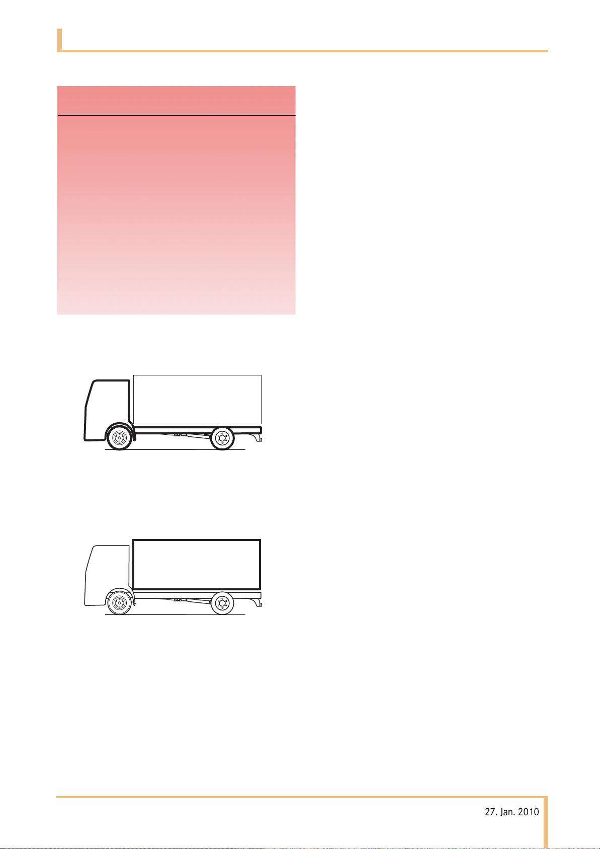
The illustrations below explain the difference between
"Basic vehicle" and "Body":
1.1 The aim of these directives
The instructions listed herein must be observed in full
to maintain the operational reliability and road sa
of the chassis and for observance of material defect
claims.
Illustrations and schematic drawings are examples
nly and serve to explain the te
o
References to regulations, standards, directives etc.
are given in keywords and serve for information only.
Additional information is available from any
Mitsubishi Fuso Service Centre
Your
Mitsubishi Fuso Truck and Bus Corp.
xts and tables.
fety
Basic vehicle
Body
Mitsubishi Fuso body/equipment mounting directives for Canter EURO V (FB/FE) Issue date: 27. Jan. 2010
! Only print out complete sections from the current versioni
7
Page 9

1 Introduction
10.Dec. 2010
1.2 Conventions
The following conventions are used in these directives:
a Warning
A warning draws your attention to possible risks of
accident and injury to yourself and others.
H Environmental note
An environmental note gives you tips on the protection of the environment.
1.2 Conventions
!
A note draws your attention to possible hazards to
your vehicle.
i
A tip contains advice or further information you may
find useful.
page
This symbol indicates the page on which you will find
further information on the subject. These pages are
cross-linked in the PDF file.
Mitsubishi Fuso body/equipment mounting directives for Canter EURO V (FB/FE) Issue date: 27. Jan. 2010
! Only print out complete sections from the current versioni
8
Page 10

1 Introduction
10.Dec. 2010
1.3 Vehicle safety
1.3 Vehicle safety
a Risk of accident and injury
The use of parts, assemblies or conversion parts
and accessories which have not been approved
may jeopardise the safety of the vehicle.
Before installing any attachments, special-purpose
bodies, equipment or carrying out any modifications to the basic vehicle and/or its assemblies,
you must read the relevant sections of the Owner’s
Handbook, as well as the operating and assembly
instructions issued by the manufacturer of the
accessories and items of optional equipment.
You could otherwise fail to recognise dangers,
which could result in injury to yourself or others.
Official acceptance by public testing bodies or
official approval does not rule out safety hazards.
In many countries, parts that make ext
he vehicle can invalidate the general op
to t
permit. Specifically, this concerns parts which:
• change the vehicle type approved in the general
operating permit
• could endanger road users
• could adversely affect exhaust emissions or noise
levels
i
Make absolutely sure that you comply with national
registration regulations as attachments, bodies,
equipment on or modifications to the vehicle will
change the vehicle type approved and may
invalidate the general operating permit.
ensive changes
erating
Notes on vehicle safety
Mitsubishi Fuso recommends
using appropriate parts only for each particular vehicle
model.
Mitsubishi Fuso body/equipment mounting directives for Canter EURO V (FB/FE) Issue date: 27. Jan. 2010
! Only print out complete sections from the current versioni
9
Page 11

1 Introduction
10.Dec. 2010
1.4 Operational reliability
a Risk of accident
Before installing any attachments, special-purpose
bodies, equipment or carrying out any modifications to the basic vehicle and/or its assemblies,
you must read the relevant sections of the Owner’s
Handbook, as well as the operating and assembly
instructions issued by the manufacturer of the
accessories and items of optional equipment.
You could otherwise fail to recognise dangers,
which could result in injury to yourself or others.
Work incorrectly carried out on electronic components and their software could prevent this equipment from working correctly. Since the electronic
systems are networked, this might also affect
systems that have not been modified.
1.4 Operational reliability
Malfunctions in the electronic systems could seriously jeopardise the operating safety of the vehicle.
Mitsubishi Fuso body/equipment mounting directives for Canter EURO V (FB/FE) Issue date: 27. Jan. 2010
! Only print out complete sections from the current versioni
10
Page 12

1 Introduction
10.Dec. 2010
1.5 Accident prevention
The body, the attached or installed equipment and any
modifications must comply with the applicable laws
and ordinances as well as work safety or accident
prevention regulations, safety rules and accident
insurer leaflets.
All technical means shall be used to avoid operating
conditions that may be unsafe or liable to cause an
accident.
All national laws, directives and registration
equirements must be complied with.
r
1.5 Accident prevention
The manufact
ment or conversion or the device manufacturer is
respon
regulati
sible for compliance with these laws and
urer of the attachment, body, equip-
ons.
Mitsubishi Fuso body/equipment mounting directives for Canter EURO V (FB/FE) Issue date: 27. Jan. 2010
! Only print out complete sections from the current versioni
11
Page 13
2 General
10.Dec. 2010
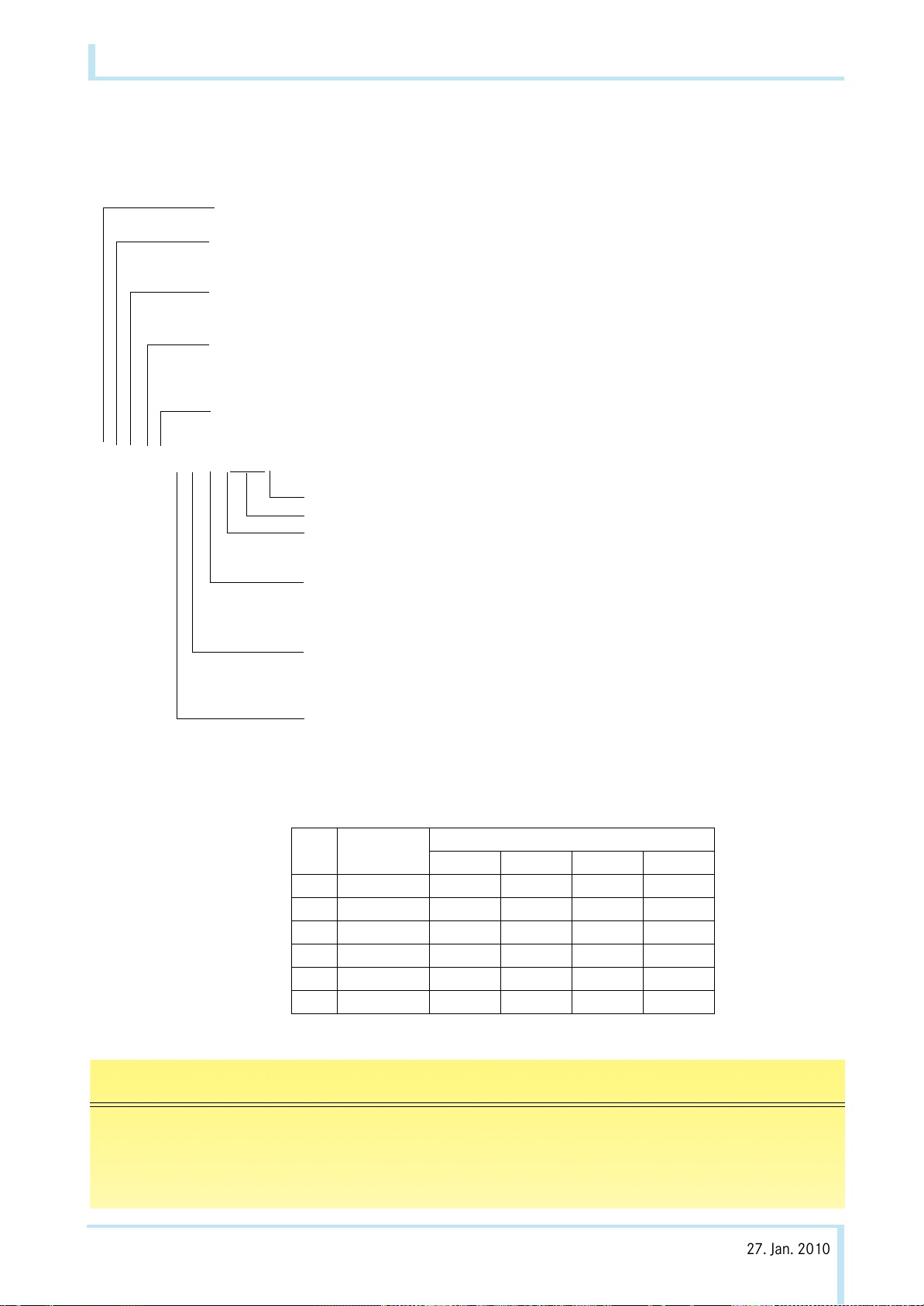
2.1 Vehicle and model designations
2.1.1 Model coding system
Cab Style
2.1 Vehicle and model designations
F: Forward control
Drive System & Basic GVM
Development Order
Suspension Type
Engine Type
F E 8 4 S G 6 W L E A 1
B: 4 x 2, GVM 3.5 tons
E: 4 x 2, GVM 3.5 to 8.0 tons
7: Standard width cab
8: Wide cab (comfort cab)
3: Leaf spring, GVM 3.5 to 6.0 tons
4: Leaf spring, GVM 3.5 to 7.0 tons
5: Leaf spring, GVM 7.0 to 8.0 tons
S: 4P10
See following table *1.
Code Destination
Steering Wheel Location
Cab Type
Rear Tyre Arrangement
EA: Portugal (MFTE)
L: Left hand
R: Right hand
S: Single cab
W: Double cab
4: Double, tyre
6: Double, tyre
Z: Double, tyre
GVM 3.5 to 6.0 tons
GVM 6.0 to 8.0 tons
GVM 6.0 to 8.0 tons with wide frame
Wheelbase (mm)
*1
Engine Model Vehicle Model&Engine Output
1 4P10 0AT2 96kw 96kw 96kw
2 4P10 0AT3 107kw 107kw
3 4P10 0AT6 129kw
4 4P10 6AT2* 96kw 96kw 96kw
5 4P10 6AT3* 107kw 107kw
6 4P10 6AT6* 129kw
*: EEV (Enhanced Environmentally - friendly Vehicle) Compliant engine
B: 2300 to 2600
C: 2600 to 2900
D: 2900 to 3200
E: 3200 to 3500
FB7 FB8 FE7 FE8
F: 3500 to 3800
G: 3800 to 4100
H: 4100 to 4400
J: 4400 to 4700
i
In this document, vehicle model with the last model code of 1 and 4, 2 and 5, 3 and 6 are identical in the
vehicle specification except for the engine model type. There are no significant differences between the nonEEV compliant engine type (4P10-0AT2,3,6) with the EEV compliant engine type (4P10-6AT2,3,6) except as
otherwise noted.
Mitsubishi Fuso body/equipment mounting directives for Canter EURO V (FB/FE) Issue date: 27. Jan. 2010
! Only print out complete sections from the current versioni
12
Page 14

2 General
10.Dec. 2010
2.1.2 Vehicle and model designation
FB73 FB73 FB83 FB83 FB83 FE74 FE84 FE84 FE85 FE85
Engine Type
Number of Cylinders
Output (kW)
(rpm)
Maximum torque (Nm)
(rpm)
Cab
Transmission
Wheelbase (mm) 2500
Permissible axle load
and weight (kg)
Permissible total
gross weight of (kg)
combination
Standard
Wide
Double
2750
2950
3350
3850
4200
4470
Front
Rear
Total
4P10T2
L4
96
3500
300
1600
•
6S420
•
•
• •
1950
2700
3500
7000 7000 7000 7000 7000 9000 10000 10000 11000 11000
4P10T2
L4
96
3500
300
1600
4P10T2
L4
96
3500
300
1600
•
•
6S420•6S420
•
•
•
•
1950
2700
3500
1950
2700
3500
2.1 Vehicle and model designations
4P10T2
6S420•6S420•6S420•6S420
L4
96
3500
300
1600
•
•
•
1950
2700
3500
4P10T3
L4
107
3500
370
1600
•
•
•
•
1950
2700
3500
4P10T2
L4
96
3500
300
1600
•
•
•
2300
3800
5500
4P10T3
L4
107
3500
370
1600
•
•
• •
2500
4500
6500
4P10T3
L4
107
3500
370
1600
4P10T3
L4
107
3500
370
1600
•
•
6S420•6S420
•
•
•
•
•
2500
4500
6500
3100
5200
7500
4P10T3
L4
107
3500
370
1600
•
•
6S420
•
•
3100
5200
7500
Engine Type
Number of Cylinders
Output (kW)
(rpm)
Maximum torque (Nm)
(rpm)
Cab
Transmission
Wheelbase (mm) 2500
Permissible axle load
and weight (kg)
Permissible total
gross weight of (kg)
combination
Standard
Wide
Double
2750
2950
3350
3850
4200
4470
Front
Rear
Total
FE84 FE84 FE85 FE85
4P10T6
6S420
L4
129
3500
430
1600
•
•
•
4P10T6
L4
129
3500
430
1600
4P10T6
L4
129
3500
430
1600
•
•
6S420•6S420
•
•
•
•
4P10T6
L4
129
3500
430
1600
•
•
6S420
•
•
•
2640
4750
6500
10000 10000 11000 11000
2640
4750
6500
3100
5200
7500
3100
5200
7500
Mitsubishi Fuso body/equipment mounting directives for Canter EURO V (FB/FE) Issue date: 27. Jan. 2010
! Only print out complete sections from the current versioni
13
Page 15

2 General
10.Dec. 2010
2.2 Technical advice and contact persons
2.2 Technical advice and contact persons
The staff members of the Daimler development
department TP/EVM., the team responsible for
conversion/body manufacturers and the body/equipment mounting directive for the overall vehicle development of Mitsubishi Fuso vehicle, issue letter of
no objection for the Canter (FB/FE) and answe
technical and design-enginee
vehicle registration and damage as the representative
of Mitsubishi Fuso. The relevant members of staff can
be contacted at:
Europe and German contacts Responsibility
Telephone: +49 (0)7 11-17-4 30 34 Mitsubishi Fuso Canter
ring questions regarding
+49 (0)7 11-17-5 17 19 Team management, standards and procedures for
r
Mercedes-Benz Actros, Axor, Atego, Econic, Zetros
and Mitsubishi Fuso Canter series
Telefax: +49 (0)7 11-17-5 21 91
Postal address: Daimler AG
HPC (in-house post code) C 108
TP/EVM
D-70546 Stuttgart, Germany
Mitsubishi Fuso body/equipment mounting directives for Canter EURO V (FB/FE) Issue date: 27. Jan. 2010
! Only print out complete sections from the current versioni
14
Page 16

2 General
10.Dec. 2010
2.3 Issue of letter of no objection
2.3.1 Letter of no objection
2.3 Issue of letter of no objection
Mitsubishi Fuso Truck and Bus Corp. does not issue
body/equipment approval certificates f
manufactured by Mitsubishi Fuso Truck and Bus Corp.
These directives only supply important information
and technical specifications to body manufacturers
explaining how to handle the product. For this reason,
Mitsubishi Fuso Truck and Bus Corp. recommends
that all work on the basic vehicle and body be carried
out in compliance with the Mitsubishi Fuso body/
equipment mounting directives.
Mitsubishi Fuso Truck and Bus Corp. advises against
attachments, bodies, equipment and modifications
which:
• are not produced in accordance with Mitsubishi
uso Body/Equipment Mounting Directives
F
• exceed the permitted maxi
ight
we
• exceed the permissible axle loads
Mits
ubishi Fuso Truck and Bus Corp. issues a letter
of no objection voluntarily based on the follo
criteria:
Mitsubishi Fuso Truck and Bus Corp.'s assess
shall be based solely on the documents submitted by
the body manufacturer carrying out the modifications.
The assessment and the endorsement shall only cover
the expressly defined scopes and their basic compatibility with the designated chassis and its connection
points or, in the case of chassis modifications, the
basic feasibility of the design for the designated
chassis.
mum gross vehicle
or bodies not
wing
ment
The letter of no objection shall not refer to the
rall design of the body, its functions or its intended
ove
field of operation. No o
design, production and assembly are performed by the
body manufacturer carrying out the modifications in
accordance with the state of the art and in compliance
with the valid Mitsubishi Fuso body / equipment
Mounting Directives – unless deviations have been
endorsed in these directives. Nevertheless, the letter
of no objection shall not release the body
manufacturer carrying out the modifications from his
product liability or his obligation to perform his own
calculations, tests and trials on the overall vehicle in
order to ensure that the overall vehicle produced by
the company meets the required specifications for
operating and road safety and handling characteristics. Accordingly, it shall be the sole duty and responsibility of the body manufacturer to ensure the compatibility of his attachments, bodies, equipment and
odifications with the basic vehicle an
m
the operating and road safety of the vehicle.
All national laws, directives and registration
requirements must be complied with.
bjection shall only apply if
d to guarantee
Mitsubishi Fuso body/equipment mounting directives for Canter EURO V (FB/FE) Issue date: 27. Jan. 2010
! Only print out complete sections from the current versioni
15
Page 17

2 General
10.Dec. 2010
2.3 Issue of letter of no objection
2.3.2 Required documents
In individual cases, the body drawings may be
submitted to the department responsible before the
start of w
the following information:
• All deviations from Mitsubishi Fuso body/
• Complet
• Attachmen
• Vehicle operating conditions, e.g.
• Certificates ("e" mark, seat tensile strength test,
Submitting the required documentati
make queries on our part unnecessary and will speed
up the approv
ork Page 14. The drawings shall contain
quipment mounting directives.
e
e data on dimensions, weights and centre
ravity (weight certificates)
of g
t of body to the chassis
– on poor roads
– in very dusty conditions
– at high altitude
– at extremely high or low ambient temperatures
c.)
et
on in full will
al procedure.
2.3.3 Legal claim
• No legal claim can be made as to the issue of a
letter of no objection.
• Mitsubishi Fuso Truck and Bus Corp. reserves th
ght to refuse the issue of a letter of no
ri
objection due
and the knowledge gained from it, even if a similar
certificate was issued in the past.
• A letter of no objection may be restricted
individual vehicles.
to
• Subsequent issuan
bjection for vehicles
o
delivered can be refused.
The body manufacturer alone shall be responsible for:
• The functionality and compatibility of its bodies
and equipment, fittings and conversions with the
c vehicle
basi
• Operating and road safety
• All bodies and equipment, fittings, conversions and
alled parts
inst
to ongoing technical development
ce of a letter of no
alrea
dy comp
leted or
e
If complex calculations and/or vehicle tests are
necessary for the no objection check, all costs
incurred must be borne by the vehicle body/conversion manufacturer or its client. The extent of testing
required is defined by the relevant department of
Mitsubishi Fuso Truck Development Page 14.
Mitsubishi Fuso body/equipment mounting directives for Canter EURO V (FB/FE) Issue date: 27. Jan. 2010
! Only print out complete sections from the current versioni
16
Page 18

2 General
10.Dec. 2010
2.4 Product safety
2.4 Product safety
Both the vehicle manufacturer and the body manufacturer must always ensure that they introduce their
scopes into the market in a safe condition and that
third parties are not at risk of any safety hazard. If this
is not adhered to they may be subject to civil, criminal
and public law consequences. Every manufacturer is
liable for the products it manufactures.
From this, it follows that the vehicle body/conversion
anufacturer therefore also bears responsibility for
m
the following:
• the operating and road safety of the body
• the operating and road safety of parts and modifi-
tions
ca
• testing and maintaining th
afety of the vehicle after th
s
mounted (the body and/or equipment must not
have a negative effect on the driving, braking or
steering characteristics of the vehicle)
• influences of parts on or modifications to the
hassis
c
• consequential damage r
tachment, equipment or modification
at
•
consequential damage resulting from retrofitted
ectrical and electronic systems
el
• maintaini
of mo
after the body
springs, propeller shafts, steering, gearbox linkage,
etc.) even in the case of diagonal torsion between
the chassis and the bodies
ng the operational reliability and freedom
vement of all moving parts of the chassis
/equipment is mounted (e.g. axles,
e operating and handling
e body/equipment is
esulting from the body,
Mitsubishi Fuso body/equipment mounting directives for Canter EURO V (FB/FE) Issue date: 27. Jan. 2010
! Only print out complete sections from the current versioni
17
Page 19

2 General
10.Dec. 2010
2.4.1 Guarantee of traceability
Hazards in your implement/body which become
known after delivery may necessitate suppleme
measures in the market (customer notification, warnings, recalls). In order to make these measures as efficient as possible, your product must be traceable after
delivery.
For this purpose and to enable the Federal Office for
Motor Vehicles' Central Vehicle Register (ZFZR) or
comparable registers abroad to be used for determining which owners are affected, we advise you to
promptly file the serial number/identification number
of your equipment/add-on part linked to the vehicle
identification number for the truck in your databases.
Similarly, it is also advisable to store the addresses of
your customers for this purpose and to grant subsequent purchasers the opportunity to register.
ntary
2.4 Product safety
Mitsubishi Fuso body/equipment mounting directives for Canter EURO V (FB/FE) Issue date: 27. Jan. 2010
! Only print out complete sections from the current versioni
18
Page 20

2 General
10.Dec. 2010
2.5 Mitsubishi three diamonds and Fuso emblem
2.5 Mitsubishi three diamonds and Fuso emblem
The Mitsubishi three diamonds and Fuso emblem are
owned or controlled by MITSUBISHI FUSO.
They must not be removed or affixed in another position.
Mitsubishi three diamonds and Fuso emblems
supplied separately must be attached at the points
specified by MITSUBISHI FUSO.
Overall appearance of the overall vehicle
If the vehicle fails to comply with the appearance and
quality standards as required by
and Bus Corp., the trademarks such as the Mitsubishi
three diamonds and Fuso emblem must be removed.
Third-party trademarks
Mitsubishi Fuso Truck
• may not be affixed next to MITSUBISHI FUSO
trademarks
Binding ruling
The Mitsubishi Fuso Brand Trademark Directive
governs the use of trademarks
on integrated bodies mounted on FB/FE chassis.
Mitsubishi Fuso Truck and Bus Corp. reserves the right
to prohibit the body manufacturer from using Mitsubishi Fuso trademarks in the event of any violations to
this body/equipment mounting directive, including
the trademark directive.
• If you have any question, contact the department
sponsible Page 14.
re
by body manufacturers
Mitsubishi Fuso body/equipment mounting directives for Canter EURO V (FB/FE) Issue date: 27. Jan. 2010
! Only print out complete sections from the current versioni
19
Page 21

2 General
10.Dec. 2010
2.6 Recycling of components
H Environmental note
When planning attachments, bodies, equipment
and modifications, and with regard to the legal
requirements according to EU Directive
2000/53/EC, the following principles for environmentally-compatible design and material selection
shall be taken into account.
Materials with risk potential, such as halogen additives, heavy metals, asbestos, CFCs and CHCs, are to
be avoided.
• It is preferable to use materials which permit
recycling and closed material cycl
• Materials and production processes are to be
lected such that only low quantities of waste are
se
g
enerated during production and that this waste
can be easily recycled.
• Plastics are to be used only where they provide
dvantages in terms of cost, function
a
• In the case of plastics, and composite materials in
articular, only compatible substanc
p
material family are to be used.
es.
or weight.
es within one
2.6 Recycling of components
• For components which are relevant to recycling,
the number of different types of plastics used must
kept to a minimum.
be
• It must be assessed whether a component can be
de from recycled material or with recycle
ma
elements.
• It must be ensured that components can be
smantled easily for recycling, e.g. by snap
di
connect
These components should generally be easily
accessible and should permit the use of standard
tools.
• Service products must be capable of being
rem
resp
• Wherever possible, components should not be
pa
used instead.
• Components in areas at risk from accidents must
be
tolerant, repairable and easy to replace.
• All plastic parts are to be marked in accordance
w
• EU Directive 2000/53/EC must be complied with.
ions or predetermined breaking points.
oved simply and in an environmentally
onsible manner by means of drain plugs, etc.
inted or coated; coloured plastic
designed in such a way that they are dama
ith VDA code of practice 260, e.g. "
parts are to be
PPGF30R".
d
ge-
Mitsubishi Fuso body/equipment mounting directives for Canter EURO V (FB/FE) Issue date: 27. Jan. 2010
! Only print out complete sections from the current versioni
20
Page 22

2 General
10.Dec. 2010
2.7 Quality system
World-wide competition, increased quality standards
demanded by the customer from the product as a
whole, national and international product liability laws,
new organisational forms and rising cost pressures
make efficient quality assurance systems a necessity
in all sectors of the automotive industry.
For the reasons quoted above, Mitsubishi Fuso Truck
and Bus Corp. urgently advises body manufacturers to
set up a quality management system with the following minimum requirements:
• Does the quality management system clearly
fine responsibility and aut
de
• Is there a description of processes/workflows?
• Are the contracts checked/is the feasibility of
constru
• Are product checks on the basis of specifie
nstructions carried out?
i
• What provisi
pr
• Are the inspection results documented
ar
• Do all employees concerned have cu
p
• Is t
• Is there a system for labelling materials/parts?
• Are quality assurance measures carried out at
sup
ction checked?
ons are made for the handling of faulty
oducts?
chived?
roof of the qualification required?
he test equipment systematically monitored?
pliers?
hority?
d
and
rrently valid
2.7 Quality system
Mitsubishi Fuso body/equipment mounting directives for Canter EURO V (FB/FE) Issue date: 27. Jan. 2010
! Only print out complete sections from the current versioni
21
Page 23

3 Planning of bodies
10.Dec. 2010
3.1 Selecting the chassis
3.1 Selecting the chassis
!
When planning attachments, bodies, equipment or
modification work, the selected vehicle must be
checked to verify whether it fulfils the necessary
requirements.
In order to ensure safe operation of the vehicle, it is
essential to choose the chassis and equipment carefully in accordance with the intended use.
Along with the selection of the correct vehicle version,
the required series and special equi
•Wheelbase
• Engine/gearbox
• Power take-offs
•Axle ratio
• Position of the centre of gravity
• Legal registration requirements
(e.g. underride guard)
• Permissible and technical gross vehicle weight
should be taken into consideration and be appropriate
for the intended use.
pment such as
!
Observe the Model. The axle designation or the load
capacity of the tyres has only limited relevance to
the gross weight of the vehicle.
i
The non-availability of a vehicle version may be an
indication that the vehicle is not suitable for the
intended application.
i
Mitsubishi Fuso body/equipment mounting directives for Canter EURO V (FB/FE) Issue date: 27. Jan. 2010
! Only print out complete sections from the current version
22
Page 24

3 Planning of bodies
10.Dec. 2010
3.2 Vehicle modifications
a Risk of accident
Do not carry out any modifications to major assemblies (steering, brake system etc.). Any modifications to the steering and the brake system may
result in these systems malfunctioning and ultimately failing. The driver could lose control of the
vehicle and cause an accident.
Alterations to the basic vehicle are permitted only
within the framework of the procedures described
in this body/equipment mounting directive.
3.2 Vehicle modifications
Standard production vehicles comply ex factory with
EU Directives and national regulations
The vehicles must still comply with EC Directives or
national regulations after modifications have been
carried out.
The body manufacturer must inform the officially
recognised approval authority or inspector of any
modifications to the chassis when the vehicle is
inspected. If necessary, present a letter of no
objection from Mitsubishi Fuso Truck and Bus Corp.
(e.g. drawing with approval note) or the applicable
body/equipment mounting directive.
Following all work on the brake system, i.e. even if
merely disassembling parts, a complete check (operation, effectiveness and visibility) of the entire brake
system must be performed.
i
Mitsubishi Fuso body/equipment mounting directives for Canter EURO V (FB/FE) Issue date: 27. Jan. 2010
! Only print out complete sections from the current version
23
Page 25

3 Planning of bodies
10.Dec. 2010
Please note the minimum weight of the vehicle
including body which is specified in the
homologation documents.
3.3 Dimensions, weights, overall vehicle height
3.3 Dimensions, weights, overall vehicle height
a Risk of accident
The vehicle tyre load capacity may not be exceeded
by overloading the vehicle beyond its specified
gross vehicle weight. The tyres could overheat and
suffer damage. This could cause you to lose control
of the vehicle and cause an accident with possible
injury to yourself and others.
Information on the permissible axle loads can be
found on the vehicle model plate.
All legal provisions governing the permissible
vehicle height must be taken into account when
planning bodies. In the Federal Republic of
Germany the permissible vehicle height is limited to
max. 4 m. In other countries (and if the vehicle is
operated on international services), comply with all
the relevant national regulations.
i
Information about changes in weight is available
from the department responsible page 14.
Dimensions and weight details can be found in the
drawings and technical data. They are based on a
vehicle that is fitted with standard equipment. Weight
tolerances of ±3% in production must be taken into
consideration (2003/19/EC).
The permissible axle loads and the maximum permissible gross vehicle weight specified in the technical
data may not be exceeded.
The technical data can be found in the vehicle documents or on the vehicle model plate.
i
Mitsubishi Fuso body/equipment mounting directives for Canter EURO V (FB/FE) Issue date: 27. Jan. 2010
! Only print out complete sections from the current version
24
Page 26
3 Planning of bodies
DRIVER SIDE
PASSENGER SIDE
10.Dec. 2010
DRIVER SIDE
DRIVER SIDE
DRIVER SIDE
DRIVER SIDE
DRIVER SIDE
DRIVER SIDE
PASSENGER SIDE
PASSENGER SIDE
PASSENGER SIDE
PASSENGER SIDE
PASSENGER SIDE
PASSENGER SIDE
3.3 Dimensions, weights, overall vehicle height
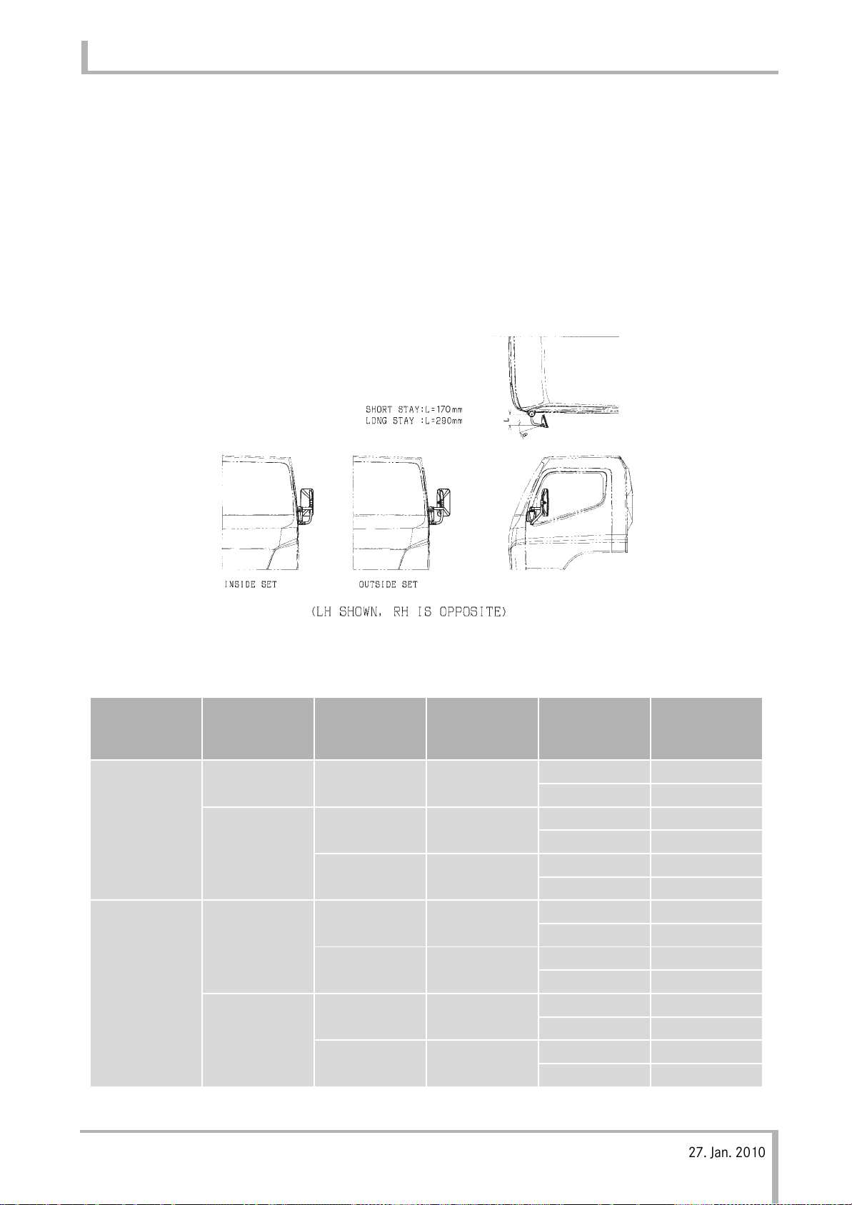
3.3.1 Maximum Rear Body Width
There is a limitation on rear body width for outside
Mirror and Lamps.
Outside mirror
The position of outside mirror for wide cabin must be
set according to the width of rear body as shown in
Fig. 1.
(The mirror is mounted on the inside position until the rear body is assembled.)
MODEL
(CABIN
WIDTH)
FB7
FE7
STD
FB8
FE8
WIDE
Fig. 1
STAY LENGTH MIRROR SET REAR BODY
WIDTH
(mm)
SHORT OUTSIDE SET 1870 to 2000 17.5°
LONG INSIDE SET 2000 to 2100 18.0°
OUTSIDE SET 2100 to 2200 19.0°
SHORT INSIDE SET 2000 to 2150 16.0°
OUTSIDE SET 2150 to 2280 17.5°
LONG INSIDE SET 2280 to 2400 18.5°
OUTSIDE SET 2400 to 2550 21.0°
SET ANGLE θ
31.0°
30.0°
31.5°
31.5°
33.5°
32.0°
34.0°
i
Mitsubishi Fuso body/equipment mounting directives for Canter EURO V (FB/FE) Issue date: 27. Jan. 2010
! Only print out complete sections from the current version
25
Page 27
3 Planning of bodies
10.Dec. 2010
3.3 Dimensions, weights, overall vehicle height
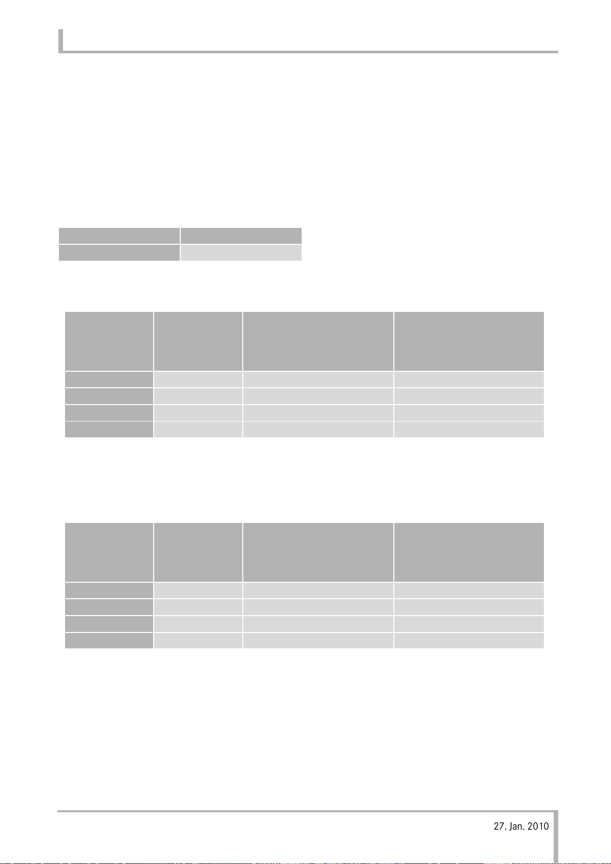
Lamps
Maximum rear body width is divided into the following
3 cases by the rear bumper in which rear combination
lamp
is installed.
When you add side direction indicator lamp, change
flasher relay to the followings and use 21watt bulb of
side direction indicator lamp.
Flasher relay
Type Parts No.
12 V MK542356
• When using no rear bumper
In case additional
MODEL Normal
FB7 / FE7 1900mm 2100mm 2200*mm
FB7-W 2070mm 2100mm 2200*mm
FB8 / FE8 2220mm 2550*mm –
FB8-W / FE8-W 2390mm 2550*mm –
*)Limited by outside mirror
• When using the rear bumper with vehicle resistration N1
(Without coupling de
MODEL Normal
FB7 / FE7 1900mm 2100mm 2200*mm
FB7-W 2070mm 2100mm 2200*mm
FB8 / FE8 2220mm 2340***mm –
FB8-W / FE8-W 2340**mm 2340***mm –
vice)
Side direction indicator
lamp on rear body sides
In case additional
Side direction indicator
lamp on rear body sides
In case additional
Side direction indicator
lamp and End outline marker lamp on rear body sides
In case additional
Side direction indicator
lamp and End outline marker lamp on rear body sides
*) Limited by outside mirror
**) Limited by rear bumper
When you mount wider rear body, change the location of rear combination lamp to rear body.
In that case, maximum rear body width is 2390mm
***)Limited by rear bumper
When you mount wider rear body, change the location of rear combination lamp to rear body.
In that case, maximum rear body width is
2550*mm
Mitsubishi Fuso body/equipment mounting directives for Canter EURO V (FB/FE) Issue date: 27. Jan. 2010
i
! Only print out complete sections from the current version
26
Page 28
3 Planning of bodies
10.Dec. 2010
• When using the other rear bumper
3.3 Dimensions, weights, overall vehicle height
Rear
MODEL
FB7 / FE7 – 1900mm 2100mm 2200*mm
FB7-W – 2070mm 2100mm 2200*mm
FB8 / FE8
FB8-W / FE8-W
*) Limited by outside mirror
**) Limited by rear bumper
When you mount wider rear body, change the rear
combination lamp to outside set or the location of
rear combination lamp to rear body.
In that case, maximum rear body width is
2550*mm
combination
lamp
inside set 2220mm 2250**mm –
outside set 2220mm 2550*mm –
inside set 2250mm 2250**mm –
outside set 2390mm 2550*mm –
Normal
In case additional
Side direction indicator
lamp on rear body sides
In case additional
Side direction indicator
lamp and End outline
marker lamp on rear
body sides
i
Mitsubishi Fuso body/equipment mounting directives for Canter EURO V (FB/FE) Issue date: 27. Jan. 2010
! Only print out complete sections from the current version
27
Page 29
3 Planning of bodies
10.Dec. 2010
3.4 About vehicle body incline
• When mounting the rear body onto the chassis,
take care to evenly balance weight on the left and
right sides. If there is difference in weight between
the left and right sides, adjust by adding counterweights or spacers on the sub-frame.
Also, use the chassis height adjustment shims (4.5
m thickness) set on the f
m
Spacer Specification
ront and rear springs.
3.4 About vehicle body incline
Material
SS400(JIS G3101)
E275A(ISO 630)
S275JR/JO(EN10025)
SUP9(JIS G4801)
55Cr3(ISO683-14)
or equivalent
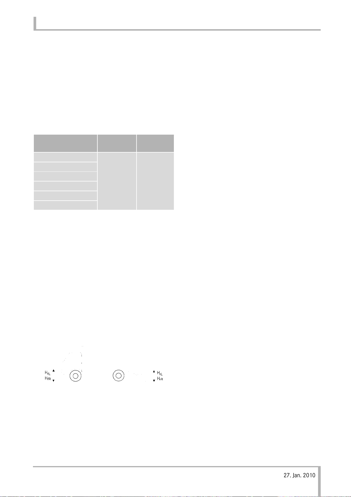
• The following are target reference values for tilting
the body of an assembled vehicle.
• Left-rig
|HfL - HfR|
|HrL - HrR|
• Front-back deviation
|(HfL - HfR) - (HrL - HrR)|
HfL: Centre height of headlamp (left side)
HfR: Centre height of headlamp (right side)
HrL: Lower height of rear end of body outer panel
HrR: Lower height of rear end of body outer panel
ht weight difference
≤ 20 mm
≤ 20 mm
(left side)
(right side)
Thickness
(mm)
4.5
≤ 20 mm
Finish
Painting for
rust
prevention
i
Mitsubishi Fuso body/equipment mounting directives for Canter EURO V (FB/FE) Issue date: 27. Jan. 2010
! Only print out complete sections from the current version
28
Page 30

3 Planning of bodies
10.Dec. 2010
3.5 Tyres
The body manufacturer must ensure that:
• the largest permissible tyres can be fitted.
• the distance between the tyre and the mudguard or
wheel housing is sufficient even when snow or a
skid chains are fitted, with the suspension fully
compressed (including any twist) (Adherence to
valid regulations).
• that the relevant information in the drawings is
rved.
obse
If the option of fitting snow and anti-skid chains
cannot be guaranteed, the operator should be
informed by the body manufacturer (operating instructions).
nti-
3.5 Tyres
a Risk of accident
Exceeding the specified tyre load-bearing capacity
or the permissible maximum tyre speed can lead to
tyre damage or failure. You can lose control of the
vehicle, cause an accident and injuries.
For this reason, only fit tyres of a type and size
approved for your vehicle and observe the tyre loadbearing capacity required for your vehicle. Observe
tyre speed index.
Comply with national regulations governing the
approval of tyres. These regulations may define a
specific type of tyre for your vehicle or may forbid the
use of certain tyre types which are approved in other
countries.
!
If you have other wheels fitted
• the brakes or components of the suspension
system could be damaged
• wheel and tyre clearance can no longer be
guaranteed
• the brakes or components of the suspension
system can no longer function correctly.
Mitsubishi Fuso body/equipment mounting directives for Canter EURO V (FB/FE) Issue date: 27. Jan. 2010
i
! Only print out complete sections from the current version
29
Page 31

3 Planning of bodies
10.Dec. 2010
3.6 Bolted and welded connections
3.6 Bolted and welded connections
3.6.1 Nuts and Bolts for Use on Frame
a Risk of accident
Do not modify any bolted connections that are relevant to safety, e.g. that are required for wheel alignment, steering or braking functions.
When unfastening bolted connections make sure
that, when work is complete, the connection again
corresponds with the original condition.
Welding work on the chassis/body may only be
carried out by trained personnel.
The body, the attached or installed equipment and
any modifications must comply with the applicable
laws and ordinances as well as work safety or accident prevention regulations, safety rules and accident insurer leaflets.
Pay attention to the following when removing nuts and
bolts used on a standard vehicle.
•Tar
get Locations
Nuts and bolts used for tightening frame crossmembers and side members (including nuts and
bolts used
together)
How to distinguish nuts and bolts
Bo
ut (6T) .... Identification at diagonal corner
N
• Handling of nuts and bolts
(a) Bolts that have been removed cannot be used
again. Tighten again using new bolts having th
same strength.
(b) Nuts and bolts must be tightened to the
foll
M10: 60 to 80 Nm
M12: 9
for tightening the fuel tank and battery
lt (8T) .... Identifying letter "8"
owing torques:
8 to 120 Nm
e
i
Further information on bolted and welded connections can be found in Section 5 "Damage prevention" page 60 and Section 6 "Modifications to
the basic vehicle" page 73.
• In particular, cross-members must be tightened
when bolts used for tightening cross-members
together are removed for moving the fuel tank and
battery.
i
Mitsubishi Fuso body/equipment mounting directives for Canter EURO V (FB/FE) Issue date: 27. Jan. 2010
! Only print out complete sections from the current version
30
Page 32

3 Planning of bodies
10.Dec. 2010
3.6.2 Welded connections
Welding work on the chassis/body may only be
carried out by trained personnel.
!
Parts which must not be welded:
• Assemblies such as the engine, gearbox, axles,
etc.
• The chassis frame (except frame modifications).
i
3.6 Bolted and welded connections
Further information on bolted and welded connections can be found in Section 5 "Damage prevention" page 60 and Section 6"Modifications to the
basic vehicle" page 73.
i
Mitsubishi Fuso body/equipment mounting directives for Canter EURO V (FB/FE) Issue date: 27. Jan. 2010
! Only print out complete sections from the current version
31
Page 33

3 Planning of bodies
10.Dec. 2010
3.7 Soundproofing
If modifications are carried out on any parts whose
operation produces noise, e.g.
•engine
• exhaust system
• air intake system
•tyres
• Noise absorbing cover, etc.
sound level measurements must be made.
3.7 Soundproofing
prevent modifications from ch
To
sound levels, it must be ensured that interior sound
levels are reduced when planning bodies.
• Noise-insulating parts fitted as standard must not
be removed or modified.
• The level of interior no
cted.
affe
i
Comply with all national regulations and directives.
In Germany, the EC Directive 70/157/EEC or
Article 49.3 of the German licensing regulations
(low-noise vehicles) must be observed.
ise must not be adversely
anging the vehicle's
i
Mitsubishi Fuso body/equipment mounting directives for Canter EURO V (FB/FE) Issue date: 27. Jan. 2010
! Only print out complete sections from the current version
32
Page 34

3 Planning of bodies
10.Dec. 2010
3.8 Exhaust system
3.8 Exhaust system
The exhaust system must not be modified.
If modification is unavoidable, consult with the department in charge of the measures page 14.
!
The original exhaust system mounting, by this we
mean the bracket components including framemounted castings, may not be modified. Modifications can lead to damage to the exhaust system.
3.8.1 Clearance between exhaust system parts
and other parts
• The exhaust pipe and exhaust gas purification
devices (Blue Tec
they are too close to or interfere with other chassis
parts, a serious accident like fire or damage by
melting could occur. Malfunction is also a possible
consequence. Secure sufficient clearance in
accordance with the standards page 112. If this
is impracticable, provide a heat shield plate to
nsure safety.
e
• Do not install th
e joint or fuel filter drain hose.
hos
Wooden and rubb
100 mm apart from the diesel particulate filter
than
(
DPF) integrated muffler and exhaust pipe. If this is
impracticable, provide a heat shielding plate
against to ensure safety.
a Risk of accident and injury
The tail pipe of a DPF-equipped vehicle can become
considerably hotter than that of a conventional
vehicle during automatic regeneration. Provide
sufficient clearance between the tail pipe and other
parts.
®
system) become so hot that if
e tail pipe under the fuel pipe, fuel
er body parts should be more
3.8.2 Exhaust gas purification devices (Blue
• Exhaust gas purification devices (Blue Tec
system) may be damaged by heavy impact against
their body or fall. When mounting, handle them
with sufficient care.
• To prevent the exhaust gas purification devices
ue Tec
(Bl
adversely affected, do not relocate the exhaust gas
purification devices (Blue Tec
temperature senor, differential pressure sensor,
lambda sensor and NOx sensor.
If temporary removal of these parts becomes
ine
these
pressure sensor hose properly, not in reverse, too
loose nor too tense. Also, securely clip hose joints
and make sure of gas-tightness.
• Exhaust gas purification devices and sensors are
riodically removed for maintenance. Install them
pe
so that
carried out without any problems.
3.8.3 Regeneration controlling DPF system
• The regeneration controlling DPF system can
maintain its full PM (particulate matter) remov
capability thanks to an automatic computer control
it employs to actively regenerate the filter (or
remove the collected PM by oxidation) and thus
prevent an overfilled ceramic filter.
Accumulated PM in DPF might not be able to be
rem
conditio
Please deal it according to the following when the
PF indicator lamp is on.
D
• Unless Engine cont
flashing or Engine control warning lamp
(amber) is on when this lamp is illuminated,
ontinue driving at a constant speed on the
c
highway.
This will remove particulate matter and
reg
• If the lamp comes on again within 30 minu
riving after it turned off, have the vehicle
d
inspec
distributor or dealer.
®
system) and sensors
Tec
®
®
system) and engine proper from being
®
system), exhaust
vitable during mounting, be sure to reinstall
parts in the original places. Connect the
removal and reinstallation work can be
oved automatically depending on use
ns (e.g. long PTO operation).
rol warning lamp (red) is
enerates DPF.
tes of
ted by an authorised Mitsubishi Fuso
ing
i
Mitsubishi Fuso body/equipment mounting directives for Canter EURO V (FB/FE) Issue date: 27. Jan. 2010
! Only print out complete sections from the current version
33
Page 35

3 Planning of bodies
10.Dec. 2010
• If engine control warning lamp (red) is flashing
or Engine control warning lamp (amber) is on
when this lamp is illuminated, have the vehicle
spected by an authorised Mitsubi
in
distributor or dealer as soon as possible.
3.8.4 Blue Tec® exhaust gas aftertreatment
Blue Tec
the exhaust gas.
Do not modify and transfer the following parts
because the performance of the system is deteriorated.
®
exhaust gas aftertreatment removes NOx in
shi Fuso
3.8 Exhaust system
• SCR muffler
•AdBlue
• Dosing module
• AdBlue hose
®
tank unit
!
The function of Blue Tec® exhaust gas aftertreatment can not work when the fuse of system is
blowout.
®
Blue Tec
of electric power to work the heating device for
freeze proofing in winter or cold region.
Don't take out the power supply for other electric
components from the fuse of Blue Tec
aftertreatment.
exhaust gas aftertreatment requires a lot
®
exhaust gas
i
Mitsubishi Fuso body/equipment mounting directives for Canter EURO V (FB/FE) Issue date: 27. Jan. 2010
! Only print out complete sections from the current version
34
Page 36

3 Planning of bodies
10.Dec. 2010
3.9 Maintenance and repairs
a Risk of accident and injury
Always have maintenance work performed at a
qualified specialist workshop possessing the
required expertise and tools in order to perform the
necessary work.
Mitsubishi Fuso recommends a Mitsubishi Fuso
Service Centre for this work.
3.9 Maintenance and repairs
• The Instruction Manual must be complied with and
supplemented as necessary.
• Stowage boxes must be fi
ps or removable rear panels.
fla
• The battery c
ntilated, with provision for air to ente
ve
• Check the condition and capacity of batteries and
ice them in accordance with the
serv
manufact
ompartment must be sufficiently
urer's specifications page 36.
tted with maintenance
r and exit.
It is absolutely essential that all safety-relevant
work and all work on safety-relevant systems is
performed by a qualified specialist workshop.
Before performing any maintenance work, always
read the technical documentation, such as the
Instruction Manual and the workshop information.
Always have all maintenance work performed at the
correct time. If this is not done, malfunctions or
failures may occur in systems that could be relevant
to safety. This could make you cause an accident,
which could result in injury to yourself or others.
Maintenance and repair of the vehicle should not be
made unnecessarily difficult by the body.
Maintenance points and major assemblies must be
easily accessible.
Any additional expenses arising from the body in
connection with warranty, maintenance or repair will
not be bo
3.9.1 Maintenance instructions
The following must be observed by the body manufacturer before delivery of the vehicle
• Due date of inspection
• The load sensing valve (LSV) must be set.
• Check the condition and capacity of batteries and
• Check the headlamp setting or have this checked
• Retigh
• Instruction Manual and directives for maintenance
• Mitsubishi Fuso recommends adapting to each
rne by Mitsubishi Fuso Truck and Bus Corp..
:
rvice them in accordance with the
se
manufacturer's specifications.
t a qualified specialist workshop.
a
ten the wheel nuts to the specified torque.
ttachments, bodies, installations or
of a
conversion
manufacturer, must be provided with the vehicle in
the language of the country of use.
individual body the scope of maintenance work
which has to be carried out on the body, coordinating it by means of the valid Mitsubishi Fuso
service systems. This applies both to the scope and
type of service work, and for determining the
service due dates for servicing intervals based on
time elapsed and distance covered.
s, which have been installed by the body
i
Mitsubishi Fuso body/equipment mounting directives for Canter EURO V (FB/FE) Issue date: 27. Jan. 2010
! Only print out complete sections from the current version
35
Page 37

3 Planning of bodies
10.Dec. 2010
3.9.2 Preparation for storing the vehicle
3.9 Maintenance and repairs
Maint
enance work on stored vehicles (in storage
for > 1 month):
!
For vehicle deliveries in winter (gritted roads). To
prevent surface damage, please clean the vehicle at
the earliest opportunity. Particular attention should
be paid to the gearbox housing and light-alloy
wheels.
Storage in an enclosed space:
• Clean the overall vehicle.
• Check the oil and coolant levels.
• Inflate the tyres to 0.5 bar above the specified
tyre pressures.
• Release the handbrake and chock the wheels.
• Disconnect the battery an
terminal
Storing the vehicle in the open (< 1 month):
s.
d grease battery lugs and
• Check the oil level once a month.
• Check the coola
• Check the tyre pressures once a month.
• Remove the battery.
Removing the vehicle from storage:
• Check the fluid levels in the vehicle.
• Correct the tyre pressures to the manufacturer's
ecifications.
sp
• Check the battery charg
• Clean the overall vehicle.
3.9.3 Battery maintenance and storage
To avoid damage to the battery, disconnect the
battery if the vehicle is to be imm
of longer than 1 week.
If the vehicle is immobilised for periods of longer than
1 month, remove the battery and store it in a dry place
at temperatures of between 0 °C to 30 °C.
Store the battery in an upright position.
The battery charge must be kept above
12.55 V at all times.
nt once a month.
e and install the battery.
obilised for a period
• Carry out the same procedure as for storing in an
enclosed space.
• Close all air inlets and set the heat
"Off".
Storing the vehicle in the open (> 1 month):
• Carry out the same procedure as for storing in an
enclosed space.
• Fold the windscre
ndscreen.
wi
• Close all air inlets and set the
Off".
"
• Remove the battery and stor
he manufacturer's specifications.
t
en wipers away from the
ing system to
heating system to
e it in accordance with
!
If the battery voltage drops below 12.1 V, the
battery is damaged and it will have to be replaced.
Leaving the vehicle parked up for long periods of
time can lead to battery damage. This can be
avoided by disconnecting the battery and storing it
appropriately.
i
Mitsubishi Fuso body/equipment mounting directives for Canter EURO V (FB/FE) Issue date: 27. Jan. 2010
! Only print out complete sections from the current version
36
Page 38

3.9.4 Work before handing over the modified
10.Dec. 2010
vehicle
The manufacturer must confirm the work and modifications carried out by making an entr
Booklet.
Checking the overall vehicle
Check the vehicle for perfect condition. All damage
must be repaired.
y in the Service
3.9 Maintenance and repairs
If it is not known how long a
hydraulic clutch operating system has been in storage,
the brake fluid must be renewed.
Checking the batteries:
Test the battery charge before handing over the
vehicle.
Checking the tyres
Before handing over the veh
are inflated to the specified p
tyres for damage. Damaged tyres must be replaced.
Checking wheel alignment
When equipment, attachments and bodies have been
mounted, it is recommended to have the toe setting
checked b
Fuso recommends a Mitsubishi Fuso Service Centre
for this work.
It is absolutely essential that all safety-relevant work
and all work on safety-relevant systems is performed
by a qualified specialist workshop.
y a qualified specialist workshop. Mitsubishi
vehicle equipped with a
icle, check that the tyres
ressure and check the
i
i
Further details are available from any
Mitsubishi Fuso Service Centre.
Mitsubishi Fuso body/equipment mounting directives for Canter EURO V (FB/FE) Issue date: 27. Jan. 2010
! Only print out complete sections from the current version
37
Page 39

3.10 Special equipment
Bracket for the second compressor (option code :
GC/CG6) is developped specially for the compressor
model CR2211L (Supplier: MITSUBISHI HEAVY
INDUSTRIES,LTD), and can be used only for the model
CR2211L.
10.Dec. 2010
a Risk of accident and injury
The use of parts, assemblies or conversion parts
and accessories which have not been approved
may jeopardise the safety of the vehicle.
Before installing any attachments, special-purpose
bodies, equipment or carrying out any modifications to the basic vehicle and/or its assemblies,
you must read the relevant sections of the vehicle
Instruction Manual, as well as the operating and
assembly instructions issued by the manufacturer
of the accessories and items of optional equipment.
You could otherwise fail to recognise dangers,
which could result in injury to yourself or others.
3.10 Special equipment
Mitsubishi Fuso recommends using equipment
available as option codes to adapt the vehicle to the
body optimally.
All code-specific special equipment is available from
your Mitsubishi Fuso Service Centre or from body
manufactur
Optional equipment (e.g. , auxiliary tanks, anti-roll
bars, etc.) or retrofitted equipment increases the
unladen weight of the vehicle.
When chassis are fitted with different springs or tyre
sizes, the frame height can change considerably in
both the laden and unladen state.
The actual vehicle weight and axle loads must be
determined by weighing before mounting.
Not all optional equipment can be installed in any
vehicle without problems. This applies, in particular,
for retrofitted equipment because the installation
space may already be occupied by other components
or the special equipment may require other components.
er advisors page 14.
i
Mitsubishi Fuso body/equipment mounting directives for Canter EURO V (FB/FE) Issue date: 27. Jan. 2010
! Only print out complete sections from the current version
38
Page 40

4 Technical threshold values for planning
10.Dec. 2010
4.1 Vehicle overhang and technical wheelbases
4.1 Vehicle overhang and technical wheelbases
a Risk of accident
The body must be designed in such a way that a
placing of excessive load weight at the rear is
prevented. It is important to comply with the points
listed below, otherwise the necessary steering and
braking forces for safe vehicle operation cannot be
transferred to the road.
• When calculating the length of the vehicle
overhang, always take into account the permissible
axle loads and the minimum front axle load.
• Comply with the minimum front axle load
page 42.
• Take the weight of special equipment into consideration when making calculations.
Mitsubishi Fuso body/equipment mounting directives for Canter EURO V (FB/FE) Issue date: 27. Jan. 2010
! Only print out complete sections from the current versioni
39
Page 41

4 Technical threshold values for planning
10.Dec. 2010
4.1 Vehicle overhang and technical wheelbases
4.1.1 Maximum vehicle overhangs
Maximum vehicle overhang
65% of wheelbase (Van body)
50% of wheelbase (Except Van body)
Van body: Body that does not accept load jutting out
in the rear of vehicle
Example: Van body, lorry, etc
i
All national laws, directives and registration
requirements must be complied with.
.
Mitsubishi Fuso body/equipment mounting directives for Canter EURO V (FB/FE) Issue date: 27. Jan. 2010
! Only print out complete sections from the current versioni
40
Page 42

4 Technical threshold values for planning
10.Dec. 2010
4.2 Weight distribution, CoG height, anti-roll bars
4.2 Weight distribution, CoG height, anti-roll bars
4.2.3 Stabilisers roll control
a Risk of accident
The body must be designed in such a way that a
placing of excessive load weight at the rear is
prevented. It is important to comply with the points
listed below, otherwise the necessary steering and
braking forces for safe vehicle operation cannot be
transferred to the road.
4.2.1 Weight distribution
Make sure that the vehicle you are building is correctly
equipped. Mitsubishi Fuso provides stabilisers for
different model series. Stabilising equipment is
required if the vehicle is used for extremely high loads.
If this equipment is unsuitable due to operating conditions (such as a need for off-road capability), the
mounting frame must be designed in a manner that
stabilises the overall vehicle in consultation with the
department responsible page 14.
Avoid one-sided weight distribution.
The wheel load (1/2 the axle load
by no more than 4%. Observe the tyre load capacity.
Example:
• Permissible axle load 5,000 kg
• Permissible wheel load distribution 2,600 kg to
2,400 kg
4.2.2 CoG height
For approval of the vehicle with body/implements
mounted, a calculation of the height o
gravity of the laden vehicle must be submitted in
accordance with EC Brakes Directive 71/320/EEC.
The calculation basis for permissible heights of centre
of gravity can be requested from the responsible
department page 14.
Mitsubishi Fuso cannot vouch for the handling,
braking and steering characteristics of vehicles with
attachments, installations or modifications for
payloads with unfavourable centres of gravity
(e.g. rear-mounted. overheight and side-mounted
loads). The vehicle body/equipment manufacturer/
converter is responsible for the safety of the vehicle in
the case of these bodies.
) may be exceeded
f the centre of
Mitsubishi Fuso body/equipment mounting directives for Canter EURO V (FB/FE) Issue date: 27. Jan. 2010
! Only print out complete sections from the current versioni
41
Page 43

4 Technical threshold values for planning
10.Dec. 2010
4.3 Steerability
a Risk of accident
The body must be designed in such a way that a
placing of excessive load weight at the rear is
prevented. The following points must be complied
with otherwise the steering and braking forces
necessary for safe driving cannot be transmitted.
To ensure sufficient vehicle steerability, the minimum
front axle load (25% of gross vehicle weight) must be
maintained under all load conditions. Consult the
department responsible in the event of any deviations
page 14.
4.3 Steerability
!
The permissible front axle load must not be
exceeded.
Observe the notes on product liability page 17.
Mitsubishi Fuso body/equipment mounting directives for Canter EURO V (FB/FE) Issue date: 27. Jan. 2010
! Only print out complete sections from the current versioni
42
Page 44

4 Technical threshold values for planning
10.Dec. 2010
4.4 Clearance for assemblies and cab
4.4 Clearance for assemblies and cab
Certain clearances must be maintained in order to
ensure the function and operational safety of assemblies.
Dimensional data in the tender drawings must be
observed.
i
Read and comply with the relevant sections of the
Instruction Manual.
4.4.1 Attachment above cab
• Observe the permissible centre of gravity location
nd the front axle load.
a
• Make sure that there is sufficient
page 241.
space for tilting.
Cab tilting range clearance
Mitsubishi Fuso body/equipment mounting directives for Canter EURO V (FB/FE) Issue date: 27. Jan. 2010
! Only print out complete sections from the current versioni
43
Page 45

4 Technical threshold values for planning
10.Dec. 2010
4.4 Clearance for assemblies and cab
4.4.2 Cab
• The distance between the cab and the body must
be keeped per layout drawings.
i
You can obtain tender drawings and technical data.
page 241.
Mitsubishi Fuso body/equipment mounting directives for Canter EURO V (FB/FE) Issue date: 27. Jan. 2010
! Only print out complete sections from the current versioni
44
Page 46

4 Technical threshold values for planning
10.Dec. 2010
4.5 Wind deflectors
4.5 Wind deflectors
4.5.1 Attaching the roof rack or drag foiler
Roof
• When attaching externally mounted parts such as
roof rack or drag foiler onto the roof, use the
exclusive mounting holes prov
ided on the roof.
• Prevent the weight of externally mounted parts
ttached to the roof from exce
a
eding 50 kg. (See
Figs. 1, 2 and 4.)
Cautions
• Use nickel-chrome plated stainless steel bolts and
washers.
• Take special care
coming scratched when attaching
be
to prevent the body from
externally
mounted parts.
• Insert packing between externally mounted parts
nd the body to prevent rusting. Use packing m
a
of EPDM rubber to prevent ozone cracking.
• After attaching externally mounted parts, coat the
tire periphery of the mounting bolts with sealer
en
• The top coat of paint must be applied to externally
unted parts before attaching to the roof. (See
mo
Fi
g. 3.)
7
ade
.
6
5
1
3
1
4
Fig. 1
2
3
2
1Section A-A
2Section B-B
380
4 Detail C
Mitsubishi Fuso body/equipment mounting directives for Canter EURO V (FB/FE) Issue date: 27. Jan. 2010
51408 (Standard cab)
1664 (Wide cab)
6 1436 (Standard cab)
1694 (Wide cab)
7500
! Only print out complete sections from the current versioni
45
Page 47

4 Technical threshold values for planning
10.Dec. 2010
4.5 Wind deflectors
2
1
(Shipped State)
DETAIL C (1)
A-A
3
7
4
6
8
5
B-B
(Shipped State)
DETAIL C (2)
114.5° (Standard cab)
16.5° (Wide cab)
232.5 (Standard cab)
31.0 (Wide cab)
3roof top
41408 (Standard cab)
1664 (Wide cab)
<Standard cab>
<Wide cab>
Fig. 2
512.0° (Standard cab)
14.5° (Wide cab)
621.5 (Standard cab)
34.5 (Wide cab)
7 roof top
8 1436 (Standard cab)
1694 (Wide cab)
Mitsubishi Fuso body/equipment mounting directives for Canter EURO V (FB/FE) Issue date: 27. Jan. 2010
! Only print out complete sections from the current versioni
46
Page 48

1 Use washer and bolt with plain washer
10.Dec. 2010
2 Coat periphery with sealer
3 Roof deck or drag foiler
4Rubber packing
4.5 Wind deflectors
1 Bolt and washer: Left/right total 8 places
(For roof deck or drag foiler)
Mitsubishi Fuso body/equipment mounting directives for Canter EURO V (FB/FE) Issue date: 27. Jan. 2010
! Only print out complete sections from the current versioni
47
Page 49

4.6 Governor and transmission power-take-off
10.Dec. 2010
4.6 Governor and transmission power-take-off
4.6.1 Governor
The electronically controlled governor (electronic governor) automatically switches to serve as special
ment governor at the time of PTO activation. Also, the cab back engine control (sensor-based) is provided for
use as engine control during PTO activation.
Engine
model
4P10 Electronically
Note. -
- *2 The accelerator pedal is inoperative as long as PTO is activated.
Governor
type
controlled
*1
The cab back engine control is not equipped in dump trucks.
Governor
& torque
Normal
engine
governor
Special
equipment
governor
Engine
control
– – Standard
Sensor-
based
Operation Applicable vehicle*
PTO-ON Specially
vehicle
equipped
vehicle
without PTO
with trans-
mission PTO
1
Vehicles
Vehicles
equip-
Remarks
2
*
Mitsubishi Fuso body/equipment mounting directives for Canter EURO V (FB/FE) Issue date: 27. Jan. 2010
! Only print out complete sections from the current versioni
48
Page 50

4.6 Governor and transmission power-take-off
10.Dec. 2010
4.6.2 Governor and torque characteristics
For special equipment governor, appropriate governor and torque characteristics during PTO activation can be
selected through change of PTO control resistor.
When g
the suitable PTO control resistor should be selected from options listed in the table below and the existing
resistor be replaced with the selected one. When a PTO is installed later in a standard vehicle, the suitable PTO
control resistor should be selected from options listed in the table below and the existing resistor be replaced
with the selected one.
(PTO resistor, governor and torque characteristics and engine control system)
overnor and torque characteristics are required to change depending on the type of mounted equipment,
Control
resistor
No.
#1 Black Natural
#2 Black Green MC854771 510 Fig. 5 Fig. 11 Fig. 17
#3 Black Yellow MC854772 820 Fig. 1 Fig. 7 Fig. 13
#4 Black Brown MC854773 1.3K Fig. 5 Fig. 11 Fig. 17
#5 Blue Natural
Molding
Color
Connec-
tor
color
color
Resis-
Part No.
MC854770 270 Fig. 1 Fig. 7 Fig. 13
MC854774 2.0K Fig. 2 Fig. 8 Fig. 14
tance
value (
Ω)
See 9.2.3 Governor and
torque characteristics
4P10-T2
(96 kW)
4P10-T3
(107 kW)
4P10-T6
(129 kW)
#6 Blue Green MC854775 3.3K Fig. 6 Fig. 12 Fig. 18
#7 Blue Yellow MC854776 5.6K Fig. 3 Fig. 9 Fig. 15
#8 Blue Brown MC854777 15.0K Fig. 4 Fig. 10 Fig. 16
*1
Note. -
In either case, the engine governor is operated in the normal characteristics when PTO is not acti-
vated, during which the cab back sensor is not working.
- *2 When one of the control resistors #3, #4, #6, #7 and #8 is installed, the accelerator pedal does not
work during the PTO activation.
*3
-
When one of the control resistors #2 and #5 is installed, the accelerator pedal works even during the
PTO activation. (When the cab back sensor and accelerator pedal are operated at the same time, the
engine is controlled by input larger in magnitude.)
Mitsubishi Fuso body/equipment mounting directives for Canter EURO V (FB/FE) Issue date: 27. Jan. 2010
! Only print out complete sections from the current versioni
49
Page 51

4.6 Governor and transmission power-take-off
10.Dec. 2010
4.6.3 PTO speed ratio and part No.
• PTO Speed Ratio and Part No.
T/M
Type
M037S6 1.412 ME533444 4P10-0AT2.3.6
i
Simply installing a PTO does not enable all of its
functions to work. It is necessary to change the
related settings of the engine ECU using the manufacturer-specified diagnostic tool and to register the
history of changes with the data server of Mitsubishi Fuso Truck & Bus Corporation before all the
PTO functions can become operational.
Please contact the department responsible for
details of the above setting changes and registration.
Speed
Ratio
P.T.O.
Part No.
Engine
• Sensor Type Cab Back Engine Control System
The control system will be fitted to any desired
sition on the vehicle a
po
rolled by a cable connected to a upper structure.
• Component Parts List
To adopt the cab back engine control system, use the
wing KIT. Table 1
follo
Table 1 (KIT Number of Cab back En
System)
KIT No. Parts Name QTY Remark
MK552405 Cab Back
Control KIT
When choosing the characteristic "hard" of the
governor please order the resistor MC854773 (#4)
separately.
Table 2 (Component Parts List of KIT No.)
nd engi
ne speed can be
gine Control
1 Sub-Harness
Length
2000 mm
cont-
page 14.
• Direction of Rotation
Direction is counter direction to engine rotation.
For details, refer to PTO Drawing
page 310.
4.6.4
Installation of non-standard PT
of no objection from department responsible.
page 14.
4.6.5 Cab back engine control syste
An engine Speed of a vehicle should be adjusted by a
cab back engine control system to match
operation speed of a upper structure unit to be
mounted.
Non standard PTO
O requires a letter
m
with an
KIT No.
Part No. Parts Name QTY
MK515114 Sensor assy cab back control 1
MK482869 Harness cab back control 1
MC854772 Unit resistor 1
i
Simply installing the components of a cab back
engine control system does not enable all of the
system's functions to work. It is necessary to
change the related settings of the engine ECU using
the manufacturer-specified diagnostic tool and to
register the history of changes with the data server
of Mitsubishi Fuso Truck & Bus Corporation before
all the cab back engine control functions can
become operational.
Please contact the department responsible for
details of the above setting changes and registration.
MK552405
page 14.
Mitsubishi Fuso body/equipment mounting directives for Canter EURO V (FB/FE) Issue date: 27. Jan. 2010
! Only print out complete sections from the current versioni
50
Page 52

• Detail of Accelerator Sensor
10.Dec. 2010
4.6 Governor and transmission power-take-off
• Lever Stroke
It’s able to choose 2 kinds of lever stroke by choosing
a clevis hole of the accelerato
Table 3 (Accelerator Sensor Specification)
SHORT STROKE
TYPE
LONG STROKE
TYPE
r sensor lever Table 3.
LEVER
HOLE
A
B
LEVER
STROKE
(mm)
31 17 N {1.7 kgf} 22 N {2.2 kgf} 40.0
50 11 N {1.1 kgf} 14 N {1.4 kgf} 64.5
LEVER OPERATING EFFORT
N {kgf}
AT IDLE AT FULL
STROKE
LEVER
LENGTH
(mm)
Mitsubishi Fuso body/equipment mounting directives for Canter EURO V (FB/FE) Issue date: 27. Jan. 2010
! Only print out complete sections from the current versioni
51
Page 53

4.6 Governor and transmission power-take-off
10.Dec. 2010
• Sensor Output Characteristic
Output characteristic and operating effort are as following figure.
• Exchange of the Resistor in the Cab
There is the resistor in the following figure location, so exchange it for the resistor in the KIT.
1
Fig. 2
1 Exchange of the Resistor. UNIT, RESISTOR: MC854772 (#3) ←MC854770 (#1)
This drawing shows LHD. RHD and LHD is symmetrical.
Mitsubishi Fuso body/equipment mounting directives for Canter EURO V (FB/FE) Issue date: 27. Jan. 2010
! Only print out complete sections from the current versioni
52
Page 54

4.6 Governor and transmission power-take-off
10.Dec. 2010
• Installation of Accelerator Sensor
The accelerator sensor operates by a connection of a harness from the vehicle side.
6
5
4
3
1 Connector for connect sub-Harness
2 Harness for accelerator
3Frame LH
4 Chassis harness
5Rear cab mounting
6 Bracket for installation
7 Sensor assy, cab back control MK515114
8 Harness, cab back control MK482869
7
8
2
1
Fig. 3
Mitsubishi Fuso body/equipment mounting directives for Canter EURO V (FB/FE) Issue date: 27. Jan. 2010
! Only print out complete sections from the current versioni
53
Page 55

4.6 Governor and transmission power-take-off
10.Dec. 2010
• An installation position must be secluded from
high pressured water for car wash, and from the
stone and mud which fly from the tyre.
Pay attention
ibration and interference with other parts.
v
• After examining the location of
the accelerator sensor by using the bracket in the
KIT.
• There is the harness connector for connections
round the vehicle left side rear cab mounting.
a
Connect it to the accelerator sensor by using the
sub-harness in the KIT.
• The direction of the hauling cable connected to
the accelerator se
possible to the lever.
• Don’t bend or twist the cable to protect an
ccelerator sensor lever.
a
• Don’t adjust the accelerator sensor stopper bolt.
• A control stroke of a cable extended from an upper
ructure unit must be set in a length not exceeding
st
a lever stroke of an accelerator sensor lever.
• Fix Connector and Harness in an interval of 200300 mm
(For steady fixation)
to a dust, a high temperature,
a installation, install
nsor lever must be as parallel as
by the band (MB249339) or the vinyl tape.
Mitsubishi Fuso body/equipment mounting directives for Canter EURO V (FB/FE) Issue date: 27. Jan. 2010
! Only print out complete sections from the current versioni
54
Page 56

5 Damage prevention
10.Dec. 2010
5.1 Electrical system
a Risk of fire
Work carried out incorrectly on the electrical
system may impair its function. This may lead to the
failure of components or parts relevant to safety.
All accident prevention regulations must be
complied with when working on the vehicle.
Comply with all national regulations and laws.
a Risk of fire
Work on live electrical lines carries a risk of short
circuit.
Before starting work on the electrical system,
disconnect the on-board electrical system from the
power source, e.g. battery.
5.1 Electrical system
Batteries
• Never place any metal objects or tools on the
batteries.
• There is a risk of short circuit if th
erminal clamp on the connected batter
t
into contact with vehicle parts. This could cause
the highly explosive gas mixture to ignite. You and
others could be seriously injured as a result.
• When disconnecting the batteries, always
sconnect the negative terminal clamp first a
di
then the positive terminal.
• When connecting the batteries, always connect the
sitive terminal clamp first an
po
terminal.
• Incorrect polarity of the supply voltage can cause
parable damage to the control units.
irre
• N
ever start the engine without a connected battery
attery terminals tightened).
(b
• Do not disconnect
le the engine is running.
whi
• If the batteries are flat, the engine can be jumpstarted using jump leads connected to the batteries
of another vehicle. Observe the Instruction Manual.
Do not use a quick charger for jump-starting.
• Only tow-start the vehicle with the batteries
connected.
• Quick-charge the batteries only after disconnecting them from the vehicle's electrical system.
Both the positive and negative terminals must be
disconnected.
or remove the battery terminals
e positive
y comes
nd
d then the negative
i
Observe the notes on operating safety and vehicle
safety in Section 1 "Introduction" page 9 and
page 10.
Mitsubishi Fuso body/equipment mounting directives for Canter EURO V (FB/FE) Issue date: 27. Jan. 2010
! Only print out complete sections from the current versioni
i
Installing additional electrical consumers
page 96.
55
Page 57

5 Damage prevention
10.Dec. 2010
Lines, plug connections and control units
• A plug connection must not be unplugged from or
plugged into the control units while the ignition
on.
• Lines must be protected from heat by means of
sulation.
in
• Route cables in such a
cur, particularly at crossover points and sharp
oc
edge
s. If necessary, use cable ducts or guide pipes.
• Do not carry out tests at connector terminals using
suitable tools (test probes,
un
may lead to contact damage and subsequent
problems. Use suitable test leads.
• The department responsible must be consulted if a
attery isolating switch is to be retrofit
b
page 14.
way that chafing cannot
wire ends, etc.). This
ted
is
5.1 Electrical system
Mitsubishi Fuso body/equipment mounting directives for Canter EURO V (FB/FE) Issue date: 27. Jan. 2010
! Only print out complete sections from the current versioni
56
Page 58

5 Damage prevention
10.Dec. 2010
5.2 Brake hoses/cables and lines
a Risk of accident
Work carried out incorrectly on the brake hoses,
cables and lines may impair their function. This may
lead to the failure of components or parts relevant
to safety.
• Fuel and hydraulic lines and brake hoses must be
covered or removed if necessary before carrying
out any welding, drilling and grinding work and
before working with cutting discs.
• After installing, fuel lines, hydraulic lines and brake
es, the system must be tested for pressure loss
hos
and leaks.
• No other l
• Lines must be protected from heat by means of
ppropriate insulation.
a
• Line routi
incre
ines may be attached to brake hoses.
ng must be designed to prevent any
ase in pressure loss.
5.2 Brake hoses/cables and lines
Comply with all national regulations and laws.
Mitsubishi Fuso body/equipment mounting directives for Canter EURO V (FB/FE) Issue date: 27. Jan. 2010
! Only print out complete sections from the current versioni
57
Page 59

5 Damage prevention
10.Dec. 2010
5.3 Mobile communications systems
5.3 Mobile communications systems
The ADR/GGVS regulations (Hazardous Materials
Road Transport Regulations and European Agreement
concerning the International Carriage of Dangerous
Goods by Road) and the manufacturer's information
and installation specification must be observed.
If mobile communication systems (e.g. telephone,
CB radio) are retrofitted, the following requirements
must be fulfilled in order to avoid malfunctions developing on the vehicle at a later stage.
Equipment
• The equipment must have official approval and
spond to DIN VDE 0879, Part 2.
corre
• The eq
• Operation of portable or mobile equipment inside
• The transmitter must be installed separately from
• Protect equi
• Observe the permissible operating temperature.
• Protect the equipment against severe mechanical
uipment must be permanently installed.
he cab is only permitted if this equipment
t
connected to a permanently installed external
aerial.
ll other vehicle electronics.
a
pment from moisture.
rations.
vib
is
Connection and wiring
• The connection should be made directly to
te
riminal inside cab page 99.
• Discon
be
• Cables should be wired via the shortest possibl
r
• Ensu
co
• The aerial and connecting cables between the
tra
routed separately from the vehicle wiring harness
in the vicinity of the body earth.
• Make sure that the aerial cable is not kinked or
crushed.
i
The notes on operating safety and vehicle safety in
Section 1 "Introduction" page 9 and page 10
must be complied with.
nect the unit from the electrical system
fore jump-starting.
oute (not looped) and twisted.
re that the system has a good earth
nnection to the body (aerial an
nsmitter, receiver and control panel must be
d equipment).
e
Aerial (for two-way radio sets)
• The aeri
al must be officially licensed.
Mitsubishi Fuso body/equipment mounting directives for Canter EURO V (FB/FE) Issue date: 27. Jan. 2010
! Only print out complete sections from the current versioni
58
Page 60

5 Damage prevention
10.Dec. 2010
5.4 Electromagnetic compatibility (EMC)
5.4 Electromagnetic compatibility (EMC)
The different electrical consumers on board the
vehicle cause electrical interference in the vehicle's
electrical circuit. At Mitsubishi Fuso, electronic
components installed at the factory are checked for
their electromagnetic compatibility in the vehicle.
When retrofitting electric or electronic systems, they
must be tested for electromagnetic compatibility and
this must be documented.
The equipment must have been granted type approval
in accordance with EC Directive 95/54/EEC and must
bear the "e" mark.
The following standards provide information on this:
• DIN 40839
• DIN 57879, Part 3
• VDE 0879, Part 3
• DC 10614 (EMC component requirements)
• DC 10613 (EMC vehicle requirements)
• EU Directive 95/54/EEC
i
The notes on operating safety and vehicle safety in
Section 1 "Introduction" page 9 and page 10
must be complied with.
Mitsubishi Fuso body/equipment mounting directives for Canter EURO V (FB/FE) Issue date: 27. Jan. 2010
! Only print out complete sections from the current versioni
59
Page 61

5 Damage prevention
10.Dec. 2010
5.5 Welding work
5.5 Welding work
a Risk of injury
Welding work in the vicinity of the airbags can
cause the restraint system to malfunction.
Welding work near the airbags is strictly forbidden.
The airbag could be triggered or may no longer
function correctly.
The legal stipulations regarding the transport and
storage of airbag units must be observed.
All laws governing explosive substances must be
complied with.
The following safety measures must be observed to
prevent damage to components caused by overvoltage during welding work:
• Disconnect the positive and negative terminals
rom the battery and cover th
f
• Connect the welding-unit earth terminal directly to
part to be welded.
the
• Do not touch electronic component
.g. control modules) and electric l
(e
welding electrode or the earth cont
welding unit.
• Before welding, cover spring to protect them from
elding spatter. Do not touch springs with welding
w
electrodes or welding tongs.
• Cover the fuel tank and fuel system (lines, etc.)
before carrying out welding work.
• Avoid welding work on ina
b.
ca
• Plug welding is only permissible in the ve
ebs of the longitudinal frame member.
w
• Welds
• Avoid welds in bends.
• The distance from a weld to the outer edge should
must be ground down and reinforced with
ngular profiles to prevent notching from welding
a
p
enetration.
ays be at least 15 mm.
alw
em.
housings
ines with the
act clamp of the
ccessible cavities in the
rtical
!
Do not connect the arc welder earth clamp to
assemblies such as the engine, gearbox or axles.
Welding work is not permitted on assemblies such
as the engine, gearbox, axles, etc.
i
Additional information on welded connections can
be found in Section 6 "Modifications to the basic
vehicles" page 73.
The following safety measures mu
prevent damage to welding par
• Do not weld any item to the frame to hold it
temporarily.
• Clean parts thoroughly with a wire brush and dry
welding.
them off b
• Make sure the paint is completely rem
lding a painted part.
we
• Use a low hydroge
lding electrode absorbs moisture when it is
we
used
use.
• When welding, maintain the optimum welding
eed and conditions for the preservation of the
sp
lding electrode.
we
• Maintain the welding current at the optimum value
for sa
• Make several short welding beads rather than
long
• Make symmetrical beads to limit shrinkage.
• Av
oid more than 3 welds at any one point.
• Avoid welding in strain hardened zones.
• When connecting the ground cable of the arc
lder, make sure to disconnect the negative
we
terminal
efore
n type welding electrode. The
, so it is necessary to dry it thoroughly before
fety.
bead.
from the battery. The ground of the
st be observed to
ts;
oved, before
one
Mitsubishi Fuso body/equipment mounting directives for Canter EURO V (FB/FE) Issue date: 27. Jan. 2010
! Only print out complete sections from the current versioni
60
Page 62

5 Damage prevention
10.Dec. 2010
welder should be connected to the side rail near
the welded part. Never connect around the engine,
transmission, propeller shaft, front and rear axles,
etc.
• When performing welding work on the chassis,
e proper measure to prevent th
tak
harnesses, rubber parts, springs, etc. from heat or
spatter.
• Do not cool parts off with water after welding.
a Risk of accident and injury
Before performing electric of arc welding as part of
vehicle repair operation, disconnect the negative (-)
cable from the battery and the connector from the
ECU. The earth cable of the welding machine should
be connected to a point as close to the welding area
as possible.
e tubes,
5.5 Welding work
Mitsubishi Fuso body/equipment mounting directives for Canter EURO V (FB/FE) Issue date: 27. Jan. 2010
! Only print out complete sections from the current versioni
61
Page 63

5 Damage prevention
10.Dec. 2010
5.6 Corrosion protection measures
General
In order to preserve the durability and quality standard
of the vehicle, measures must be taken to protect it
against corrosion when the vehicle is modified and
after installing bodies and fittings.
Information on the design, execution of work and the
requirements of the materials and components to be
used with regard to corrosion protection is listed
below.
To achieve good corrosion protection, the areas of
design (1), production (2) and materials (3) must be
perfectly matched.
5.6 Corrosion protection measures
Optimum corrosion protection
Materials
Corrosion
protection
Design Production
Mitsubishi Fuso body/equipment mounting directives for Canter EURO V (FB/FE) Issue date: 27. Jan. 2010
! Only print out complete sections from the current versioni
62
Page 64

5 Damage prevention
10.Dec. 2010
5.6 Corrosion protection measures
Disassembly of components
If the body manufacturer makes structural modifications to the chassis, the corrosion protection in the
affected areas must
tion standards of Mitsubishi Fuso. The areas must also
be finished with appropriate paintwork. Information on
approved Mitsubishi Fuso refinishing paint suppliers is
available on request from the responsible department
page 14.
Damage to components
If components are damaged during disassembly
ratches, scuff marks), they must be professionally
(sc
repaired. Th
openings. Two-component epoxy primers are particularly suitable for repair work.
is applies especially for drilled holes and
be restored to match the produc-
Cutting of components
When cutting and grinding work is carried out, the
djacent painted components must
a
against flying sparks and shavings. Grinding dust and
shavings must be carefully removed because these
contaminants can spread corrosion. Edges and drilled
holes must be cleanly deburred in order to guarantee
optimum corrosion protection.
Corrosion protection on reinforcements and
tings
fit
Reinforcements and fittings must receive adequa
anti-corrosion priming prior to installation. In addit
to galvanising, cataphoretic dip-priming and zinc-rich
paint in sufficient coatings have proved satisfactory
for this purpose.
be protected
te
ion
Mitsubishi Fuso body/equipment mounting directives for Canter EURO V (FB/FE) Issue date: 27. Jan. 2010
! Only print out complete sections from the current versioni
63
Page 65

5 Damage prevention
10.Dec. 2010
5.7 Corrosion prevention in welding work
5.7 Corrosion prevention in welding work
In order to avoid crevice corrosion at weld seams, the
welds should be made in accordance with the
examples shown.
Preparation
The welding area must be free from corrosion, grease,
dirt or similar contamination. If painted surfaces
be welded, the paint coat must first be removed by
grinding or chemical stripping. If this is not done, the
paint will burn and the residues can impair corrosion
resistance.
After welding work
• Remove drilling shavings.
• Deburr sharp edges.
• Remove any burned paint and thoroughly prepare
rfaces for painting.
su
• Prime and paint all unprot
• Preserve cavities with wax preservative.
• Carry out corrosion protection measures on the
underbody and frame parts.
ected parts.
are to
AB
Example: Weld seams
A – Suitable
B – Unsuitable
i
Plug and slot welds, particularly on horizontal
surfaces, should be avoided due to the risk of corrosion. If they are unavoidable, these welds must
receive additional preservation. Furthermore, avoid
designs which allow moisture to accumulate. These
must be fitted with additional drainage holes or
gaps in the weld seam.
Mitsubishi Fuso body/equipment mounting directives for Canter EURO V (FB/FE) Issue date: 27. Jan. 2010
! Only print out complete sections from the current versioni
64
Page 66

5 Damage prevention
10.Dec. 2010
5.8 Bolted connections
Finish-painted components
If painted parts are to be bolted together, the coats of
paint must not cause settling in the bolted conne
tions. In such cases, hard, high-density coatings such
as cataphoretic immersion primers or powder
coatings should be used. The coat thicknesses should
be kept as small as possible (cataphoretic immersion
primer approx. 20 µm, powder coatings approx.
100 µm).
• If using bolts with serrations under the head, an
ditional top coat must be applied to to
ad
paint damage.
• The use of hexagon socket or Torx socket bolts in
a horiz
can
conditions, leading to corrosion.
ontal position is to be avoided, as moisture
accumulate in the bolt head under certain
c-
uch up any
5.8 Bolted connections
Fasteners
In areas susceptible to corrosion always use bolts,
nuts, etc. with corrosion resistance (>480
test according to ISO 9227) regardless of the required
strength class. This standard is satisfied, e.g. by bolts
with electroplating and additional thick-coat sealing
and zinc platelet coatings with sealer (e.g. Dacromet
or Deltaseal), refer to VDA 235-104 recommendation.
Information on identifying suitable coatings can be
obtained from your local bolt supplier.
For details on bolted connections see Section 3
page 30.
h saline fog
Mitsubishi Fuso body/equipment mounting directives for Canter EURO V (FB/FE) Issue date: 27. Jan. 2010
! Only print out complete sections from the current versioni
65
Page 67

5 Damage prevention
10.Dec. 2010
Preventing contact corrosion
Direct contact between materials with different electrode potentials can lead to corrosion of the less noble
mat
erial when exposed to moisture and salt ions.
5.8 Bolted connections
When selecting materials, avoid the following combinations:
• Chrome/nickel-steel with aluminium
• Chrome/nickel-steel with zinc-coated steel
Insulation by coating
Contact corrosion can be prevented by using insulation such as washers, sleeves or bushings. Even in this
e, however, the connecting points must not be
cas
persistently exposed to moisture.
Vehicle cleaning and care
When the vehicle is handed over to the body manufacturer, it must immediately be cleaned of salt and dirt.
If it is to be stored for some time, the vehicle must be
preserved.
During modification it must be ensured that loadbearing components are additionally protected
against aggressive chemicals and environmental influences. If the vehicle comes into contact with chemicals or salts (e.g. snow-clearing operations), it must be
cleaned thoroughly at regular intervals.
1
2
1Insulating washer
2 Insulating sleeve
2
1
!
A conductive connection occurs if two different
metals are brought into contact with each other
through an electrolyte (e.g. air humidity). This
causes electrochemical corrosion and the less base
of the two metals is damaged. The further apart the
two metals are in the electrochemical potential
series, the more intense electrochemical corrosion
becomes.
For this reason, electrochemical corrosion must be
prevented by insulation or by treating the components accordingly, or it can be minimised by selecting suitable materials.
Mitsubishi Fuso body/equipment mounting directives for Canter EURO V (FB/FE) Issue date: 27. Jan. 2010
! Only print out complete sections from the current versioni
66
Page 68

5 Damage prevention
10.Dec. 2010
5.9 Painting work
H Environmental note
Paints and lacquers are harmful to health and to the
environment if they are not handled correctly.
Dispose of paints and lacquers in an environmentally responsible manner.
Paint compatibility should be checked when repainting. In order to avoid colour variations on painted
bodies, Mitsubishi Fuso recommends that paints be
used only if they have been tested and approved for
the vehicle model in question. Information on the
primers used at the factory and on Mitsubishi Fuso
colour numbers can be obtained from the relevant
department page 14.
5.9 Painting work
Mask the following areas before painting:
•Sealing surfaces
•Windows
• Contact areas between the wheels
and wheel hubs
• Contact areas for wheel nuts
• Breathers on gearboxes, axles, etc.
•Disc brakes
• Door locks
• Door retainers in the rear door hinges
• Coupling flanges of drive shafts and power take-
offs
•Spring mounting area
!
Do not exceed a temperature of 80 °C for drying
the paint.
Mitsubishi Fuso body/equipment mounting directives for Canter EURO V (FB/FE) Issue date: 27. Jan. 2010
! Only print out complete sections from the current versioni
67
Page 69

5 Damage prevention
10.Dec. 2010
5.10 Leaf springs
Parabolic springs
• Damaged parabolic springs must be completely
replaced.
• Individual spring leaves may not be renewed.
•
Only use spring leaves which have been tested and
proved for the vehicle model in
ap
Reinforcement by installing additional spring
leaves is not permitted.
• Do not damage the surface or the corrosion
rotection of the spring leaves when carrying out
p
stallation work.
in
• Before carrying out welding work, cover the spring
aves to protect them against welding spatter.
le
not touch springs with welding electrodes or
welding tongs.
question.
Do
5.10 Leaf springs
Mitsubishi Fuso body/equipment mounting directives for Canter EURO V (FB/FE) Issue date: 27. Jan. 2010
! Only print out complete sections from the current versioni
68
Page 70

5 Damage prevention
10.Dec. 2010
5.11 Tilting the cab
a Risk of injury
Before tilting the cab, please make sure that you
read the "Tilting the cab" section in the detailed
Instruction Manual.
You could otherwise fail to recognise dangers,
which could result in injury to yourself or others.
5.11 Tilting the cab
Mitsubishi Fuso body/equipment mounting directives for Canter EURO V (FB/FE) Issue date: 27. Jan. 2010
! Only print out complete sections from the current versioni
69
Page 71

5 Damage prevention
10.Dec. 2010
5.12 Towing and tow-starting
a Risk of accident and injury
Before towing or tow-starting, please make sure
that you read the "Towing" section in the detailed
Instruction Manual. You could otherwise fail to
recognise dangers and cause an accident, which
could result in injury to yourself or others.
!
5.12 Towing and tow-starting
Failure to observe the instructions in the Instruction
Manual can result in damage to the vehicle.
Mitsubishi Fuso body/equipment mounting directives for Canter EURO V (FB/FE) Issue date: 27. Jan. 2010
! Only print out complete sections from the current versioni
70
Page 72

5 Damage prevention
10.Dec. 2010
5.13 Risk of fire
a Risk of fire
Work on live electrical lines carries a risk of short
circuit.
Before starting work on the electrical system,
disconnect the on-board electrical system from the
power source, e.g. battery.
With all bodies make sure that neither flammable
objects nor flammable liquids can come into
contact with hot assemblies (including through
leakages in the hydraulic system) such as the
engine, gearbox, exhaust system, turbocharger, etc.
Appropriate caps, seals and covers must be
installed on the body in order to avoid the risk of
fire.
5.13 Risk of fire
Mitsubishi Fuso body/equipment mounting directives for Canter EURO V (FB/FE) Issue date: 27. Jan. 2010
! Only print out complete sections from the current versioni
71
Page 73

5.14 Storing and handing over the vehicle
10.Dec. 2010
5.14 Storing and handing over the vehicle
Storage
To prevent any damage while vehicles are in storage,
Mitsubishi Fuso recommends that they be serviced
and stor
specifications page 36.
Handover
To prevent damage to the vehicle or to repair any existing damage, Mitsubishi Fuso re
vehicle be subjected to a full function check and a
complete visual inspection before it is handed over
page 37.
ed in accordance with the manufacturer's
commends that the
Mitsubishi Fuso body/equipment mounting directives for Canter EURO V (FB/FE) Issue date: 27. Jan. 2010
! Only print out complete sections from the current versioni
72
Page 74

6 Modifications to the basic vehicle
10.Dec. 2010
6.1 General
6.1 General
a Risk of injury
Do not modify any bolted connections that are relevant to safety, e.g. that are required for wheel alignment, steering or braking functions.
When unfastening bolted connections make sure
that, when work is complete, the connection again
corresponds with the original condition.
Welding work on the chassis/body may only be
carried out by trained personnel.
The body, the attached or installed equipment and
any modifications must comply with the applicable
laws and directives as well as work safety or accident prevention regulations, safety rules and accident insurer leaflets.
i
Further information on bolted and welded connections can be found in Section 3 "Planning of bodies"
page 30 and Section 5 "Damage prevention"
page 55.
Mitsubishi Fuso body/equipment mounting directives for Canter EURO V (FB/FE) Issue date: 27. Jan. 2010
! Only print out complete sections from the current versioni
73
Page 75

6 Modifications to the basic vehicle
Further information on the material can be found in
chapter 9.5.3 "Frame section modulus" > page272
10.Dec. 2010
6.2 Chassis frame material
If the frame is extend, the material of the extension
element and reinforcing bracket must have the same
quality and dimensions as the standard chassis frame.
See the respective tender drawings for the longitudinal frame member dimensions.
Material: FB, FE (except FE8-JZ) . MJSH440 or
SAPH440 (JIS)
(SAE J410950X or
the equivalent)
FE8-JZ. . . . . . . . . . . . . . HTP540
6.2 Chassis frame material
Mitsubishi Fuso body/equipment mounting directives for Canter EURO V (FB/FE) Issue date: 27. Jan. 2010
! Only print out complete sections from the current versioni
74
Page 76

6 Modifications to the basic vehicle
For further information, contact the department
responsible > page14
10.Dec. 2010
6.3 Drilling work on the vehicle frame
6.3 Drilling work on the vehicle frame
Drilling work on the longitudinal frame members
Parts which must not be drilled:
• In the top and bottom flanges of the chassis frame.
H
oles in the rear end of the frame are an except
Holes must not, however, be drilled in sections
with a supporting function for the last axle or on
parts fastened to the frame.
• Near sectional changes in the longitudinal frame
ember, e.g. frame drop and frame taper.
m
t load application points (e.g. in the immediate
• A
inity of spring brackets).
vic
Existing (factory-made) holes in t
flanges of the chassis frame must not be enla
(exception: mounting holes for the end crossmember).
These bore holes must not be used to secure assemblies.
he upper and lower
ion.
rged
Holes may be drilled in the web of the longitudinal
mber for special cases (se
me
•Distance (a):
At least 30 mm from inside edge of longitudinal
frame member.
• Distance between holes
At least 30 mm
• Maximum hole diameter (d): 11 mm
No load may be applied to the centre of the web of the
longitudinal member (diaphragm effect). If this is
unavoidable, make sure that there is a large area of
support on both sides of the web.
Deburr and ream all holes after drilling.
e below).
(b):
Mitsubishi Fuso body/equipment mounting directives for Canter EURO V (FB/FE) Issue date: 27. Jan. 2010
! Only print out complete sections from the current versioni
a
b
a
d
75
Page 77

6 Modifications to the basic vehicle
10.Dec. 2010
6.3 Drilling work on the vehicle frame
Drilling work on the crossmembers
• The holes and distances between the holes should
conform to the values specifie
Crossmember type Hole
diameter
• Alligator type
(see Fig. 1)
• Channel type
(see Fig. 2)
Note*: Maintain the dimensions of previously drilled
s.
hole
9 mm
max.
d in the chart below.
Centre-tocentre distance of
holes
30 mm*
min.
Alligator type
2
1
3
• Holes should be more t
end of the side rail flange or the end of th
• Holes in the web of the channel type crossmember
le be 50 mm min. from the end of the
shou
crossmember. (Refer
• Holes in the flange should be more than 25 mm
the end.
from
• Holes should be dri
urved part of the flange.
c
han 100 mm away from the
e gusset.
to Fig. 2)
lled more than 20 mm from the
Channel type
4
5
6
1 100 mm min
2 DIA 9 mm max
3 25 mm min
Fig. 1
7
Fig. 2
4 100 mm min
5 DIA 9 mm max
6 25 mm min
7 50 mm min (Web surface)
Mitsubishi Fuso body/equipment mounting directives for Canter EURO V (FB/FE) Issue date: 27. Jan. 2010
! Only print out complete sections from the current versioni
76
Page 78

6 Modifications to the basic vehicle
10.Dec. 2010
6.4 Welding work on the vehicle frame
6.4 Welding work on the vehicle frame
Welding work on the frame may only be carried out by
trained personnel.
Welding must not be performed on the upper or lower
flange of the chassis frame (except for wheelbase and
frame extensions).
Connect the earth terminal of the arc welder directly
to the part of the vehicle to be welded.
• Use only completely dry lime basic jacket
ectrodes. Electrode diameter 2.5 mm.
el
•
Maximum current per mm electrode diameter
40 A.
• Weld only with electrodes connected to the
ositive pole of a direct current source. Always
p
weld from bottom to top.
• MIG welding is permissible. Welding wire thickness
2 mm.
1 to 1.
• The yield point and tensile strength of the w
rial must be at least equal to that of
mate
material to be welded.
• Welds must be ground down and reinforced with
ngular profiles to prevent notching from welding
a
p
enetration. Avoid welds in bends. There should be
at least 15 mm between the weld and the outer
ges.
ed
• Fine-grain steel with elongations at frac
> 380 N/mm² in MC quality and in the sheet
kness for frame sections should not be pre
thic
heated.
ture of
elding
the
-
• Do not weld anything within 20 mm of the curve in
the side rail.
1
Fig. 1
1 No welding within 20 mm of this part.
Mitsubishi Fuso body/equipment mounting directives for Canter EURO V (FB/FE) Issue date: 27. Jan. 2010
! Only print out complete sections from the current versioni
77
Page 79

6 Modifications to the basic vehicle
10.Dec. 2010
6.4 Welding work on the vehicle frame
i
Further information on welded connections can be
found in Section 5 "Damage prevention"
page 60.
• Avoid defects such as deposited metal cracking,
toe crack, blow holes, slag inclusion, under cut,
poor penetration, etc.
12 3
45 6
1 Deposited metal cracking
2Toe crack
3 Blow hole
Fig. 2
4 Slag inclusion
5Under cut
6Poor penetration
Mitsubishi Fuso body/equipment mounting directives for Canter EURO V (FB/FE) Issue date: 27. Jan. 2010
! Only print out complete sections from the current versioni
78
Page 80

6 Modifications to the basic vehicle
10.Dec. 2010
6.5 Reinforcement on side rail
6.5 Reinforcement on side rail
Avoid adding outside reinforcement to the side rail, as
this can actually produce stress concentrations which
cause cracks in the frame. If additional reinforcement
is absolutely necessary, perform the procedures
described below.
• An L-shaped stiffener is recommended. The
hannel type stiffener should not be used as it
c
produces a gap w
ith the side rail flange.
• Position the L-shaped stiffeners so the flange will
e on the side of the side rail stress that receives
b
the tens
ion (the lower surface within the
wheelbase and the upper side for the overhang).
• Do not align the stiffener ends with the ends of the
ub side rail that have alr
s
eady been installed.
(Refer to Fig. 1)
• Do not position the ends of the stiffener near stress
oncentration locations such as the rear surface
c
of
the cab, spring hangers, crossmember ends, etc.
• Do not cut the outer stiffener ends vertically. They
hould be cut at an angle of less than
s
45°. (Refer
to Fig. 1)
12345
• Attach the stiffeners and the side rail by
riveting or
plug welding on the web.
• When drilling rive
e rails should be processed together. The
sid
difference betwee
t holes, the outer stiffeners and
n the rivet and hole diameters
should be less than 0.7 mm. The rivet holes should
be separated from the side rail corners by 20 mm.
• Use rivet which hove a 10 mm diameter. Arrange
hem in a zig-zag pattern.
t
• Separate ri
eat damage or distortion when t
h
vets and bolts at least 70 mm to prevent
hey are plug
welded.
• Holes for plug welding should be at least 30 mm
a and arranged in a zig-zag pattern.
di
• Posit
• The pitch for rivets and pl
ion the end of the stiffeners 25 mm - 30 mm
from the hole
s for rivets or plug welds.
ug welds should be 70
- 150 mm. Keep the pitch small near the edge
mm
of the stiffener.
•
Do not drill any additional holes in the side rail
lange. Only use the holes whi
f
ch have been already
drilled in the flange.
10
1 10mm diameter rivet or 30mm diameter plug welding
arranged in zig-zag pattern
2 Do not align the stiffener end with the sub side rail
3Sub side rail
4 Pitch: 70-150 mm
5 The pitch at the end should be smaller
Mitsubishi Fuso body/equipment mounting directives for Canter EURO V (FB/FE) Issue date: 27. Jan. 2010
! Only print out complete sections from the current versioni
6
978
Fig. 1
645° or less
7 Front Shackle Hanger
8 Do not connect stiffener to the hanger
9 Do not position the end near a crossmember
10 45° or less
79
Page 81

6 Modifications to the basic vehicle
10.Dec. 2010
6.5.1 Others
Never drill or grind any notches in the side rail, crossmember flange, or crossmember gusset.
1
6.5 Reinforcement on side rail
2
3
1 Side rail
2 Crossmember gusset
3Crossmember
Mitsubishi Fuso body/equipment mounting directives for Canter EURO V (FB/FE) Issue date: 27. Jan. 2010
! Only print out complete sections from the current versioni
80
Page 82

6 Modifications to the basic vehicle
10.Dec. 2010
6.6 Brake systems
a Risk of accident
Work carried out incorrectly on the brake system
may impair its function. This may lead to the failure
of components or parts relevant to safety. This
could cause you to lose control of the vehicle and
cause an accident with possible injury to yourself
and others.
All accident prevention regulations must be complied
with when working on the vehicle.
6.6 Brake systems
Disc brake
!
Do not impede cooling by attaching spoilers below
the bumper, additional hub caps or brake disc
covers, etc.
Comply with all national regulations and laws.
i
After any modifications the brake system must be
tested for proper operation and approved by a technical inspection authority otherwise the operating
permit will be invalidated.
Further information can be found in Section 5
"Damage prevention" page 57.
Mitsubishi Fuso body/equipment mounting directives for Canter EURO V (FB/FE) Issue date: 27. Jan. 2010
! Only print out complete sections from the current versioni
81
Page 83

6 Modifications to the basic vehicle
10.Dec. 2010
6.7 Modifications to the wheelbase
The wheelbase should not be extended or shortened
because considerations for the propeller shaft length,
balance, position of centre bearings, brake piping
sh
len
gth are required.
aft
and harness
If this is unavoidable, contact the department responsible page 14.
6.7.1 Prohibition on modifying the propeller
a Risk of accident
It is strictly prohibited to modify the propeller shaft
by welding or other means to change its length.
An improperly modified propeller shaft may cause
vibration during operation, which in turn may cause
cracks and fractures in the clutch housing, separation of the propeller shaft, and other dangerous
conditions, possibly resulting in a serious accident.
6.7 Modifications to the wheelbase
Mitsubishi Fuso body/equipment mounting directives for Canter EURO V (FB/FE) Issue date: 27. Jan. 2010
! Only print out complete sections from the current versioni
82
Page 84

6 Modifications to the basic vehicle
10.Dec. 2010
6.8 Frame modifications
6.8 Frame modifications
• The maximum permissible axle loads must not be
exceeded, while the minimum front axle load must
be exceeded.
• Rear underride guard: fastened in the same way as
a standard vehicle.
on
• Extend the mount
ing frame to the end of the frame.
6.8.1 Frame extension of rear overhang
Extension of the rear overhang may be required.
Extension procedures are listed below.
• Adde
• Reinforcement material.
• Rear overhang extension
d material as an extension member.
Use steel plates: page 74
The cross section form should be the same as that
of the si
be
Use the same for the frame. page 74
The plate thickness should be 3.2 mm - 4.5 mm.
(a) Added material length less than 300 mm.
de rail rear end. The plate thickness should
6.0 mm.
Butt weld continuously from the outside as
shown in Fig. 1 and finish the welded surface by
grinding. No reinforcement is required for
normal usage, but reinforcement should be
added as shown in (b) in order to support heavy
weights on the overhang extension.
1
3
90°
Fig. 1
1 Extension
2 Finish surface with grinder
3 Side rail
2
1
1 mm
Mitsubishi Fuso body/equipment mounting directives for Canter EURO V (FB/FE) Issue date: 27. Jan. 2010
! Only print out complete sections from the current versioni
83
Page 85

6 Modifications to the basic vehicle
10.Dec. 2010
(b) Added material length of 300 mm or more.
Attach reinforcement on the inside of the side
rail as shown in Fig. 2. Butt weld the additio
material and the side rail continuously, and then
finish the welded surface by grinding.
more than 200 mm
2
nal
D
B
6.8 Frame modifications
A
1
C
C
D
3
2
90°
1
1 mm
Note: There should be no contact within 10 mm
of the asterisk mark.
Unit: mm
ABCD
50 35 50 35
Fig. 2
1 Extension
2 Reinforcement
3 Side rail
• Exercise great care in welding the reinforcement to
the lower face of the rear side rail where it is
tapered.
Mitsubishi Fuso body/equipment mounting directives for Canter EURO V (FB/FE) Issue date: 27. Jan. 2010
! Only print out complete sections from the current versioni
84
Page 86

6 Modifications to the basic vehicle
10.Dec. 2010
• Cautions for finishing the side rails.
Be especially careful when finishing the flange end
of the butt-welded side rails. Ensure a clean finish
by grinding the weld so it is free of undercut, pileup
or convex bead.
6.8 Frame modifications
Under cut
Fig. 3
Pile up
Fig. 4
Mitsubishi Fuso body/equipment mounting directives for Canter EURO V (FB/FE) Issue date: 27. Jan. 2010
! Only print out complete sections from the current versioni
85
Page 87

6 Modifications to the basic vehicle
10.Dec. 2010
6.9 Mounting equipment on the side rail
6.9 Mounting equipment on the side rail
a Risk of accident
The use of parts, assemblies or conversion parts
and accessories which have not been approved
may jeopardise the safety of the vehicle.
Before installing any attachments, special-purpose
bodies, equipment or carrying out any modifications to the basic vehicle and/or its assemblies,
you must read the relevant sections of the vehicle
Instruction Manual, as well as the operating and
assembly instructions issued by the manufacturer
of the accessories and items of optional equipment.
You could otherwise fail to recognise dangers,
which could result in injury to yourself or others.
6.9.1 Mounting equipment on the side rail
• Attach a stiffener to the inside of the side rail as
shown in Fig. 1 when installing bolts to support
heavy components on t
will prevent cracks in the frame due to resonance
of the component if the static load caused by the
weight of the component exceeds 100 kg of force
for each bolt.
Example:
he side rail overhang. This
Official acceptance by public testing bodies or official approval does not rule out safety hazards.
All national laws, directives and registration requirements must be complied with.
Holder panel
Fig. 1
• As a rule, avoid attaching additional equipment
together with components (fuel tank, battery, etc.)
which are already installed to the frame side.
When this is absolutely necessary, increase the
size of the bolts, or the number of bolt locations, to
decrease the stress on each bolt.
Mitsubishi Fuso body/equipment mounting directives for Canter EURO V (FB/FE) Issue date: 27. Jan. 2010
! Only print out complete sections from the current versioni
86
Page 88

6 Modifications to the basic vehicle
carriers)
10.Dec. 2010
6.9 Mounting equipment on the side rail
6.9.2 Wheel chocks
Mounting
• In a suitable bracket so that they cannot rattle.
• Secured to prevent loss.
• Ensure good accessibility.
6.9.3 Mudguards and wheel arches
• The distance from the tyre to the mudguard or
wheel arch must be sufficient, even when snow
chains or an
spring compression (including under torsion). The
dimensional data in the tender drawings must be
observed.
• On chassis with standard bore holes for mudguard
rackets, use these bore holes to secure t
b
brackets.
6.9.4 Spare wheel
Mounting
• Install under the frame, on the side of the frame or
on the body in accordance with the chassis
dr
awing.
• It must be easily accessible and easy to handle.
• Double-secured to prevent loss. (only for Germany)
• The Spare tyre - carrier
When remodelling the tyre-carrier, followings must
be paid attention:
(a) A single worker
tyre.
(b) Interference is not caused with parts other than
e intended stopper when tightening th
th
on the tyre carrier.
(c) The worker can attach even burst tyres.
(d) The tightening section is p
becoming loose.
Example 1: Clamped tyre-carrier
• The tightening bo
• Double nuts must be used for tightening.
• The structure having a height d
• The structure having a stopper for
ti-skid chains are fitted and at full
can easily remove or attach the
revented from
lt must be 30 mm or
r.
longe
enting falling on the bracket.
prev
ent
prev
falling.
ing tightening nuts and bolts from
he
e tyre
ifference for
Example 2: Hoiste
• The structure must hav
below the hoisting plate.
• The struct
of the hoi
• The structure must have a lock for
reventing the tyre from
p
(e) The tightening bolt must be M10,
n equivalent product. (clamped tyre-
or a
carriers)
(f) The tyre sha
ard, backward, left and right directions.
forw
(clamped tyre-carrier
(g) Take care to prevent injury when hoisting tyres.
(hoisted
(h) Tightening bolts must be tig
f at lea st 49 N m an d by a f orce at le
o
at handles. The tyre-carrier must be designed
to have enough contact area to support the
tyre securely.
(hoisted tyre-carriers)
(i) The height diffe
le
that enables the same effect. (hoisted tyre-
tyre-carriers)
ast 10 mm, or the lifter must be of a shape
d tyre-carrier
e a spring inserted
ure must prevent reverse rotation
sting shaft.
falling
7 T strength
pe must limit movement in the
s)
htened to a torque
ast 290 N
rence on the lifter must be at
1
1 Height difference
carriers)
(j) When manufacturing the carrier, apply a tensile
oad of 4900 N or more on the lifter. (hoisted
l
tyre-carriers)
(k) Affix a Caution Plate indicating the
recommended tightening torque 49 Nm at a
position that can be easily seen during
operation.
Mitsubishi Fuso body/equipment mounting directives for Canter EURO V (FB/FE) Issue date: 27. Jan. 2010
! Only print out complete sections from the current versioni
87
Page 89

6 Modifications to the basic vehicle
10.Dec. 2010
6.9 Mounting equipment on the side rail
• Carry out the following tests with the carrier
attached to the body or in a similar state.
(a) Tensile strength test
(clamped tyre-carrier)
Apply the following load face down at the centre
f the disc wheel with a tyre attached to the
o
er.
carri
P=W x α x β
P:
W : ty
α :
β : Required safety ratio of 1.3
(hoisted tyre-carrier)
Apply the following load face down via the
hoisting plate.
P=(Po x γ ± W x α) x β
P: Test load
Po : Load applied on chain by tightening
Test load
re of maximum set weight
Load multiple of 2.5
torque during standard tightening
(b) Hoisting strength test
(hoisted tyre carrier)
Fix the hoisting plate, and apply the following
es on the carrier.
torqu
T=To x γ x β
T: Test torque
To : Standard tightening torque
β : Required safety ratio of 1.3
γ : Load multiple of 1.5
As a result of this test, carrier co
e free from detrimental deformation.
b
(c) Operating durability
Hoist a tyre of maximum allowable weight,
tighten to a torque of 5 kgfm, and then winch
down. Repeat t
times. (This test needs be carried out continuously.) As a result of this test, operation must
main uninterrupted and carrier components
re
must be f
his series of operations 200
ree from detrimental deformation.
mponents must
W : tyre of maximum set weight
α : Load multiple of 2.5
β : Required safety ratio of 1.3
γ : Load multiple of 1.5
As a result of this test, carrier component
be free from detrimental deformati
on.
s must
(d) Looseness resistance
Increase and decrease vibrations of 1 g (9.8 m/
sec2) (need not be 1 g during reson
vibrations) and 8.3 Hz to 50 Hz (500 to 3,000
times per minute) on the supporting device in
the vertical direction of the carrier mount
continuously for one hour taking at least 5
minutes for each reciprocal movement.
As a result of this test, the carrier device must
e free from detrimental looseness.
b
ance
Mitsubishi Fuso body/equipment mounting directives for Canter EURO V (FB/FE) Issue date: 27. Jan. 2010
! Only print out complete sections from the current versioni
88
Page 90

6 Modifications to the basic vehicle
Clank handle center line
Body center line
Ideal center line
10.Dec. 2010
6.9 Mounting equipment on the side rail
• Cautions when Attaching the Crank Handle Guide
The spare tyre crank handle guide is not attached
to the frame on FE single-tyre vehicles. So,
the procedure below when attaching the crank
handle guide onto the body.
Crank handle guide
2
1
8
A
9
follow
3
Fig. 2
10
4
5
Arrow view A
6
7
1 Clank handle boss
2 Clank handle C/L
3Guide plate
4 Rear body part
56° or less
Handle guide plate
50
R
Ø20
50
70
Fig. 3
Crank handle guide (reference)
Ø8
A
10
6Body C/L
725
8134
9370
10 Ideal C/L
R
10
A handle guide plate of any external shape may be
used. However, make sure that the hole is machined
to the shape shown in the figure ont the left.
The angle between the handle center line and ideal
center line must be 6° or less.
Ø16
R30
R30
150
41
Mitsubishi Fuso body/equipment mounting directives for Canter EURO V (FB/FE) Issue date: 27. Jan. 2010
Arrow A
! Only print out complete sections from the current versioni
700
115
Fig. 4
89
Page 91

6 Modifications to the basic vehicle
10.Dec. 2010
6.9 Mounting equipment on the side rail
6.9.5 Front underrun protection
All class N2 vehicles put into circulation must comply
with EC Directive 2000/40/EC (front underride
protect
70/156/ EEC, Annex II. The intended operation of a
vehicle is to a great extent determined by the bodywork, so that the structure, design and equipment of
the chassis must be carefully considered both with
and without the front underrun protection. It is not
possible to retrofit a front underrun protection on
Canter. Mitsubishi Fuso recommends that the
approval and intended use be clarified with the authorities responsible beforehand.
ion) in order to conform with Directive
Mitsubishi Fuso body/equipment mounting directives for Canter EURO V (FB/FE) Issue date: 27. Jan. 2010
! Only print out complete sections from the current versioni
90
Page 92

6 Modifications to the basic vehicle
10.Dec. 2010
6.9 Mounting equipment on the side rail
6.9.6 Rear underrun protection
In Germany, Article § 32b of the German vehicle licensing regulations requires an underrun protecti
• the distance between the rear of the vehicle and
the final rear axle is more than 1,000 mm
• the ground cl
in body parts exceeds 700 mm for the unladen
ma
vehicle across the e
Exceptions to this regulation are semitrailer tractor
vehicles, machines and vehicle
cannot be fulfilled if an underrun protection is fitted.
If an underride guard is required, it must comply with
EC Directive 70/221/EEC.
The underride guard must be mounted as far back as
possible.
Installation dimensions:
• maximum height of underrun protection (unladen
vehicle) above road surface: 550 mm
• maximum width = width of rear axle (outer tyre
ge).
ed
• minimum width: = Width of rear axle – 100 mm
on each
• crossmember section height at least 100 mm.
• edge radius at least 2.5 mm.
earance of the chassis as well as the
ntire width.
s whose purpose
side (widest axle is authoritative)
on when
.
The rear underrun protection fitted at the factory
omplies with EC Directive 70/221/EEC. No modifi-
c
ations may be made. If modifications are unavoi-
c
dable, they must be clarified in advance with the
vehicle licensing agency responsible.
Mitsubishi Fuso body/equipment mounting directives for Canter EURO V (FB/FE) Issue date: 27. Jan. 2010
! Only print out complete sections from the current versioni
91
Page 93

6 Modifications to the basic vehicle
10.Dec. 2010
6.9 Mounting equipment on the side rail
Check strength of underrun protection and its mounting in accordance with EC Directive 70/221/EEC.
At maximum deformation, the distance from the end
of the body to the end of the underrun protection at
the load points may not exceed 400 mm.
P
1
max.100
a = Rear axle width
, P2, P3 = Load application points
P
1
P
2
P
3
P
2
P
1
700-1000
Mitsubishi Fuso body/equipment mounting directives for Canter EURO V (FB/FE) Issue date: 27. Jan. 2010
! Only print out complete sections from the current versioni
92
Page 94

6 Modifications to the basic vehicle
10.Dec. 2010
6.9 Mounting equipment on the side rail
6.9.7 Side underrun protections
According to EC Directive 89/297/EEC, a side
underrun protection is sti
permissible gross vehicle weight in excess of 3.5 t.
• Components may be mounted in the side underrun
protections, e.g. battery bo
lights, reflectors, spare wheel and tool box,
provided that the specified clearances are
maintained. Brake, hydraulic lines and other parts
may not be secured to side underrun protections.
• The function and accessibility of all equipment on
e vehicle must not be impaired.
th
• T
he underrun protections must extend
ontinuously from the front to the rear wherev
c
possible.
• Adjacent parts may overlap. The overlapping edge
st point to the rear or downwards.
mu
pulated for vehicles with a
x, air tank, fuel tank,
er
Mitsubishi Fuso body/equipment mounting directives for Canter EURO V (FB/FE) Issue date: 27. Jan. 2010
! Only print out complete sections from the current versioni
93
Page 95

6 Modifications to the basic vehicle
10.Dec. 2010
6.10 Cab
Modifications to the cab must not have a negative
effect on the operation or strength of assemblies or
control elements or on the strength of load-bearing
parts.
The tilting cab must not be fixed rigidly to the bodywork. If any interventions to the cab are planned they
must be co-ordinated with the department responsible page 14.
• If the tilting cab is fixed rigidly to the bodywork, a
lettter of no objection from the department
responsible is required page 14.
• If additio
torsio
necessary on the short cab with three-point
bearing without tilting hydraulics. If the weight of
the bodies amounts to more than 50 kg, a fourpoint bearing with tilting hydraulics and a
letter of no objection from the department
responsibl
• The cont
three diamonds and emblem m
with page 19.
nal parts are installed or removed, a
n bar with increased aligning torque m
e are required page 14.
ent relating to in Sec
tion 2.5 Mitsubishi
ust be complied
ay be
6.10 Cab
Mitsubishi Fuso body/equipment mounting directives for Canter EURO V (FB/FE) Issue date: 27. Jan. 2010
! Only print out complete sections from the current versioni
94
Page 96

6 Modifications to the basic vehicle
10.Dec. 2010
6.11 Seats and bench seat
a Risk of injury
Modifications to or work incorrectly carried out on
a restraint system (seat belt and seat belt anchorages, belt tensioner or airbag) or its wiring, could
cause the restraint systems to stop functioning
correctly, e.g. the airbags or belt tensioners could
be triggered inadvertently or could fail in accidents
in which the deceleration force is sufficient to
trigger the airbag. For this reason, never carry out
modifications to the restraint systems.
Comply with all national regulations and directives.
6.11 Seats and bench seat
The retrofitting of original seats and/or bench seats is
only permitted and possible if the necessary preinstallations exist in the vehicle, such as suitable floor
assembly, reinforced cab/cab suspension. For all
other seat retrofittings, corresponding evidence (belt
checks, tensile tests) is required as part of an endorsement check carried out by the department responsible page 14.
Mitsubishi Fuso body/equipment mounting directives for Canter EURO V (FB/FE) Issue date: 27. Jan. 2010
! Only print out complete sections from the current versioni
95
Page 97

6 Modifications to the basic vehicle
10.Dec. 2010
6.12 Electrics/electronics
a Risk of accident
Before installing any attachments, special-purpose
bodies, equipment or carrying out any modifications to the basic vehicle and/or its assemblies,
you must read the relevant sections of the Owner’s
Handbook, as well as the operating and assembly
instructions issued by the manufacturer of the
accessories and items of optional equipment.
You could otherwise fail to recognise dangers,
which could result in injury to yourself or others.
Work incorrectly carried out on electronic components and their software could prevent this equipment from working correctly. Since the electronic
systems are networked, this might also affect
systems that have not been modified.
Malfunctions in the electronic systems could
seriously jeopardise the operating safety of the
vehicle.
6.12 Electrics/electronics
Electrical Wiring
The electrical circuits have been designed in particular
with the emphasis on safety. In this respect, a highcurrent
in order to prevent fires caused by shorting during
accidents. So, follow the procedures below when
making changes to the electrical circuits.
• Additional Wiring
fuse box is provided at the side of the battery
(a) Use wires of the same gauge and color as the
inal wires when making wiring extensions.
orig
(b) Connect wi
rminals and then insulate them completely
te
with tape
connect wires by just twisting the stripped ends
together.
(c) Do not use sulfuric acid for soldering.
(d) Do not extend or shorten the battery cables. In
ase of change of battery cable wiring due to
c
the t
extension or shortening of the battery cables.
Replace the cables with the ones with specified
length.
(e) Be especially careful not to modify the type of
lamps, location or slack of wiring connected to
c
mo
vable components between the starter and
the frame.
(f) Wiring should be made along the rear body
rts, the frame, etc., and ne
pa
individually in midair.
(g) Clamp all wires securely in locations away from
moving parts or sharp corners on the chassis
and body. Use grommets whenever routing
wires through metal plates in order to prevent
electrical short circuits due to installation
damage. (Fig. 1)
res securely by soldering or crimping
or other material. Never attempt to
ransfer of the battery, be sure not to make
ver extend it
1
3
2
Fig. 1
1 Grommet
2Wire
3 Metal plate
Mitsubishi Fuso body/equipment mounting directives for Canter EURO V (FB/FE) Issue date: 27. Jan. 2010
! Only print out complete sections from the current versioni
96
Page 98

6 Modifications to the basic vehicle
10.Dec. 2010
6.12 Electrics/electronics
(h) Wires should never pass along brake tubes or
fuel lines. Observe the following clearances.
Wiring Clearance mm (in.)
allel 10 (0.39) or more
Par
Crossed 20 (0.79) or more
(i) Position wires more than 200 mm (7.87 in.)
away from parts which become extremely hot
such as the exhaust pipe or muffler. Install a
heat insulator if heat protection is necessary.
(j) Gravel which is thrown up by the wheels can
amage lamp wiring. Install metal covers to
d
protect the w
(k) Tape wires together with the nearest chassis
iring harnesses if possible.
w
(l) Route wires along the chassi
re already installed. Wires should be clamped
a
wi
th vinyl tape, and wrapped up widely with thin
metal sheets (rubber or vinyl coated). Do not
use weak vinyl tape that could fall off soon due
to engine heat.
(m)Wires connecting engine and transmission
omponents should run along previously
c
instal
led harnesses to allow them to absorb
motion. Also allow adequate slack to prevent
them from contacting other components.
(n) When connecting plugs, place the female end in
e power source side to prevent a sho
th
to the body even if the terminal comes off.
iring.
s harnesses that
rt circuit
(o) Use coated or protected tape when clamping
wires.
2
1
Fig. 3
1PVC covering
2 Spot welding
(p) Bonding or temporary clamps should be used
only for additional support.
(q) Use standard wiring clamp intervals as shown
low:
be
Harness diameter Clamp intervals mm (in.)
5 (0.20) max 300 (11.81) max
5-10 (0.20-39) approx. 400 (15.75)
10-20 (0.39-0.79) approx. 500 (19.69)
(r) Wires may come in contact with edges of metal
parts; increase the number of clamps and cover
the edges with protectors to prevent damages
due to vibrations.
3
1 Socket (female)
2Plug (male)
3 Power source side
4Ground side
Mitsubishi Fuso body/equipment mounting directives for Canter EURO V (FB/FE) Issue date: 27. Jan. 2010
1
Fig. 2
! Only print out complete sections from the current versioni
2
4
97
Page 99

6 Modifications to the basic vehicle
10.Dec. 2010
(s) When passing electrical wiring through the cab
floor, use the grommet shown in Fig. 4.
• Cut the grommet as shown in Fig. 5
• Drill an appropriate additional hole for the
lug. (excluding T/M with P.T.O. ve
p
• Pass the harness through and tape.
hicles)
6.12 Electrics/electronics
1 Grommet
1
Fig. 4
Cut off
(3)
(Ø10)
Grommet
Fig. 5
Mitsubishi Fuso body/equipment mounting directives for Canter EURO V (FB/FE) Issue date: 27. Jan. 2010
! Only print out complete sections from the current versioni
98
Page 100

6 Modifications to the basic vehicle
10.Dec. 2010
• Mounting Location of Optional Terminal Inside Cab
A
6.12 Electrics/electronics
Total with Body
chassis terminal : 7A
Total with Body
chassis terminal : 7A
Total with Body
chassis terminal : 7A
Total with Body
chassis terminal : 5A
Mitsubishi Fuso body/equipment mounting directives for Canter EURO V (FB/FE) Issue date: 27. Jan. 2010
! Only print out complete sections from the current versioni
99
 Loading...