

Page 1

Owner’s Manual
2012 Model
Pub. No. MH996530
Page 2
OWNER AND VEHICLE INFORMATION
OWNER NAME:
USER/COMPANY NAME:
MAILING ADDRESS:
CITY, STATE: ZIP:
VEHICLE IDENTIFICATION NUMBER:
DATE OF DELIVERY (WARRANTY START DATE): / /
MO. DAY YR.
SELLING DEALER IMPRINT HERE
Page 3

Page 4

Foreword
Thank you for purchasing a Mitsubishi Fuso FE, FG Truck.
This Owner’s Manual explains proper vehicle handling, simple maintenance practices, and the periodic maintenance schedule to ensure that you are able to drive
your vehicle safely and comfortably.
As improper use of the vehicle may result in a breakdown or cause an accident, we
urge you to read this handbook thoroughly before operating the vehicle.
Please keep this manual in the vehicle so it is always available for reference. If you
sell the vehicle, make sure the next owner receives this manual and is aware of its
contents.
© 2011 Mitsubishi Fuso Truck & Bus Corporation Printed in Japan
Page 5
Reading the handbook
Q The information in this manual is accurate as of the time of printing. Because of differ-
ences in specifications and improvements that may be added after preparation of this
manual, some of the explanations and illustrations in this handbook may not apply to your
vehicle.
Q The following symbols are used throughout this handbook:
: optional equipment
: requests that reader should refer to the page of the number indicated.
Q This manual contains important cautionary instructions and supplementary information
under the following four headings which identify the nature of the instructions and information:
DANGER
WARNING
CAUTION
NOTE: Suggestions or supplementary information for more effi-
Q California Proposition 65 Warning
Precautions that should be taken when handling dangerous substances such as battery fluid in order to prevent a
serious injury or death
Precautionary instructions, which, if not observed, could
result in serious injury or death.
Precautionary instructions, which, if not observed, could
result in damage to or destruction of equipment or parts.
cient use of equipment or better understanding.
DANGER
THIS PRODUCT CONTAINS OR EMITS CHEMICALS KNOWN TO THE STATE OF
CALIFORNIA TO CAUSE CANCER AND BIRTH DEFECTS OR OTHER REPRODUCTIVE HARM.
Page 6

CONTENTS
1. Recommendation to drivers . . . . . . . . . . . . . . . . . . . . . . . . . . . . . . . . . . . . . . . . . . . 1-1
2. Warning labels . . . . . . . . . . . . . . . . . . . . . . . . . . . . . . . . . . . . . . . . . . . . . . . . . . . . . . 2-1
3. Opening and closing . . . . . . . . . . . . . . . . . . . . . . . . . . . . . . . . . . . . . . . . . . . . . . . . . 3-1
4. Seat and steering wheel adjustments . . . . . . . . . . . . . . . . . . . . . . . . . . . . . . . . . . . 4-1
5. Switches and controls . . . . . . . . . . . . . . . . . . . . . . . . . . . . . . . . . . . . . . . . . . . . . . . . 5-1
6. Instruments and warning lamps . . . . . . . . . . . . . . . . . . . . . . . . . . . . . . . . . . . . . . . . 6-1
7. Starting and driving . . . . . . . . . . . . . . . . . . . . . . . . . . . . . . . . . . . . . . . . . . . . . . . . . . 7-1
8. 4WD operation <FG models> . . . . . . . . . . . . . . . . . . . . . . . . . . . . . . . . . . . . . . . . . . 8-1
9. Heating and air conditioning . . . . . . . . . . . . . . . . . . . . . . . . . . . . . . . . . . . . . . . . . . . 9-1
10. Interior equipment and accessories . . . . . . . . . . . . . . . . . . . . . . . . . . . . . . . . . . . . 10-1
11. In cold weather . . . . . . . . . . . . . . . . . . . . . . . . . . . . . . . . . . . . . . . . . . . . . . . . . . . . . 11-1
12. Simple inspection and service . . . . . . . . . . . . . . . . . . . . . . . . . . . . . . . . . . . . . . . . 12-1
13. Useful advice for emergencies . . . . . . . . . . . . . . . . . . . . . . . . . . . . . . . . . . . . . . . . 13-1
14. Service data . . . . . . . . . . . . . . . . . . . . . . . . . . . . . . . . . . . . . . . . . . . . . . . . . . . . . . . 14-1
15. Maintenance schedule . . . . . . . . . . . . . . . . . . . . . . . . . . . . . . . . . . . . . . . . . . . . . . . 15-1
16. Alphabetical index . . . . . . . . . . . . . . . . . . . . . . . . . . . . . . . . . . . . . . . . . . . . . . . . . . 16-1
17. Maintenance record . . . . . . . . . . . . . . . . . . . . . . . . . . . . . . . . . . . . . . . . . . . . . . . . . 17-1
Each chapter has a table of contents on its first page.
Page 7

Page 8

1-1
1. Recommendation to drivers
Chassis and engine numbers ............................................................................................ 1-2
Vehicle identification number (VIN) .................................................................................... 1-3
Maintenance ...................................................................................................................... 1-4
Fuels .................................................................................................................................. 1-5
DEF (Diesel exhaust fluid) ................................................................................................. 1-8
Handling of the new vehicle ............................................................................................. 1-13
Reporting safety defects .................................................................................................. 1-14
Obtaining service ............................................................................................................. 1-14
Page 9
1-2 Recommendation to drivers
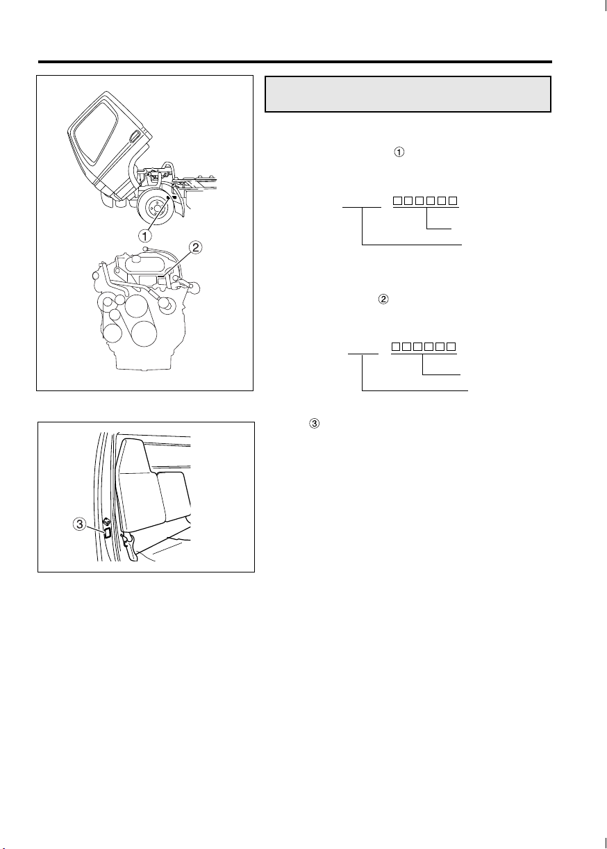
Chassis and engine numbers
1 Chassis number
The chassis number is indicated on the left
frame, near the left front wheel.
Example: FEC52 -
Chassis number
2 Engine number
The engine number is indicated on the front side
of the cylinder head.
Example: 4P10 -
Vehicle model
Z21444
Z21326
Engine number
Engine model
A label indicating the vehicle information including the vehicle model, chassis number, and engine
model is affixed to the pillar of the assistant driver’s
door.
Page 10
<Crew-cab model>
Country J: Japan
, Vehicle type L, 6: Incomplete vehicle
Gross vehicle weight / A: 10,001 to 14,000 lbs. / Hydraulic
Brake system B: 14,001 to 16,000 lbs. / Hydraulic
Line M: FEC52S
Series (wheel base) C: 2.6 to 2.89 m (8.53 to 9.48 ft.)
Cab chassis type 1: Chassis cab for Mitsubishi Fuso
and make
Engine A: 2.998 L Diesel turbo charged and charge air cooled
Check digit
Model year C: 2012
Plant K: Kawasaki
Plant sequential number
1-3
Vehicle identification number (VIN)
The VIN is stamped on a plate that is located as
shown in the illustration.
The VIN comprises 17 numbers and letters, the
meanings of which are listed below.
Z11959
Z11769
J RA6L G CA1 K
C: 16,001 to 19,500 lbs. / Hydraulic
N: FEC72S
P: FEC72W
R: FEC92S
S: FGB72S
E: 3.2 to 3.49 m (10.49 to 11.44 ft.)
G: 3.8 to 4.09 m (12.46 to 13.41 ft.)
H: 4.1 to 4.39 m (13.45 to 14.40 ft.)
K: 4.7 to 4.99 m (15.41 to 16.37 ft.)
Page 11
1-4 Recommendation to drivers
4,000 km
(2,500 miles)
Z21323
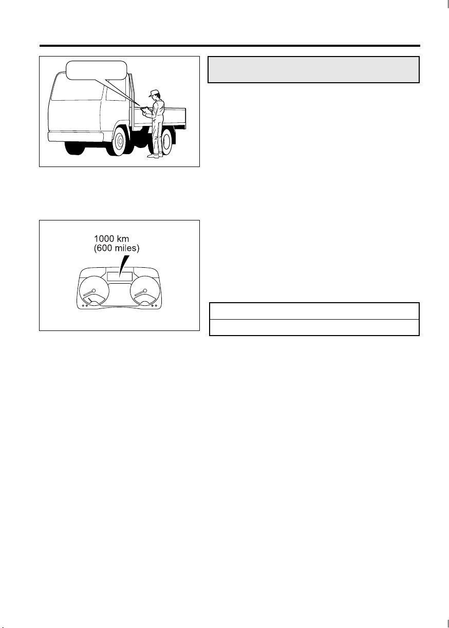
Maintenance
Checking your vehicle at regular intervals is very
important for maximizing performance and extending service life. It is recommended that you make a
habit of performing the following inspections.
This manual describes simple maintenance checks
and procedures that can be carried out by the
owner. If you have difficulty or your vehicle needs
maintenance work that is not shown in this manual,
please refer to an authorized dealer.
1 First maintenance at 4,000 km (2,500
miles)
After you have driven the first 4,000 km (2,500
miles), your vehicle requires a special inspection
and adjustments to compensate for the initial settlement of various parts. When the distance has been
reached, have your vehicle inspected by an authorized dealer by showing them this Owner’s Manual.
2 Pre-operational check
Make a habit of checking your vehicle at the start of
every day’s operation. This will ensure safe and
comfortable operation. P. 12-11
Z01367
3 Periodic inspection
In addition to maximizing the vehicle’s working life,
regular inspections also help prevent accidents.
Periodic inspection is based on either the distance
traveled (odometer reading) or period of use
(months/years).
The intervals between and content of periodic
inspections are as shown in the Maintenance
Schedule section. Please adhere to the maintenance schedule carefully.
Page 12

1-5
Fuels
Use only diesel fuels conforming to the following
recommendations, without any additives, for diesel
engines installed in Mitsubishi Fuso trucks.
1 Diesel-fuel properties
The following recommendations concerning diesel
fuel used with Mitsubishi Fuso diesel engines are
given for optimum fuel economy and performance.
Use condition Recommendation
Normal operation at
temperatures above
–12°C (10°F).
Operation at temperatures below –12°C
(10°F), or long-hour noload operation.
Biodiesel fuel can be used if it has a 5% or lower
blend ratio and complies with ASTM D-6751.
NOTE:
* ASTM is an acronym for the American Society for
Testing and Materials which recommends fuel containing 0.0015% – basis 15 ppm sulfur or less sulfur
content.
Note that a sulfur content exceeding 0.0015% –
basis 15 ppm sulfur deteriorates the performance of
emission control device.
ASTM D-975
Grade Ultra Low Sulfur
Grade 2-D*
ASTM D-975
Grade Ultra Low Sulfur
Grade 1-D*
To meet fuel requirements, it is necessary to obtain
cooperation from a reputable fuel oil supplier. Both
fuel suppliers and users are responsible for keeping
fuel clean.
2 Diesel fuel to be used in your engine
Use only a ultra low sulfur diesel fuel (with a sulfur
content of 15 ppm or lower) for refueling your Mitsubishi Fuso diesel engine. Otherwise, the catalyst
inside the diesel particulate filter (DPF) will not work
effectively and the DPF’s performance of removing
small particles (particulate matter or PM) in exhaust
gases will be degraded. Furthermore, your truck will
not meet emission regulations if you replenish it
with a non-approved fuel.
Page 13
1-6 Recommendation to drivers
3 Danger of fire and explosion by using
mixed fuel
Fuel containing 5% gasoline has a flash point as
low as 0°C (32°F), which can lead to a fire or explosion while the engine is running.
DANGER
NEVER MIX DIESEL FUEL WITH GASOLINE,
GASOHOL OR ALCOHOL.
USE OF FUEL MIXED WITH ONE OR MORE
OF THESE COULD LEAD TO A FIRE OR
EXPLOSION INVOLVING SERIOUS INJURY,
DEATH OR PROPERTY DAMAGE. IF YOU
ACCIDENTALLY USE GASOLINE OR ALCOHOL WHEN REFUELING THE VEHICLE,
REMOVE ALL OF IT FROM THE FUEL SYSTEM.
4 Adverse effects of mixed fuel on engine
Using diesel fuel mixed with gasoline, alcohol, or
both, has the following adverse effects on the
engine:
• Fuel viscosity becomes lower, resulting in
excessive wear, damage, and failure of fuel system parts.
• Difficulty in starting the engine will result due to
a reduced cetane number.
CAUTION
• The lower the cetane number, the more likely
internal engine damage will occur.
• Do not add antifreeze agents or other sub-
stances to the fuel. They could damage the
engine’s fuel injection system.
• If the fuel tank cap and breather (air hole)
become so dirty that the breather gets
blocked, the fuel tank may deform and the
fuel injection system may fail. Be sure to
clean them regularly.
Page 14
1-7
5 Refueling
WARNING
• Stop the engine before fueling.
• Never smoke when fueling since diesel
fuel could ignite or explode.
Never operate lighters or other items that
emit sparks.
• If you inadvertently put gasoline in the fuel
tank, pump it all out. Running the engine
with gasoline in the tank could cause a fire
or explosion endangering your or other
people’s lives.
CAUTION
Be careful not to allow the engine to run out of
fuel. Engine stall resulting from an empty tank
could cause damage to the fuel injection system.
NOTE:
If the vehicle runs out of fuel, air will enter the fuel
system. Once air enters the system, you cannot
start the engine even after refueling. The air must
be bled out of the fuel system before the engine can
be started. To bleed the fuel system, hold the starter
switch in the “ON” position for 30 seconds and then
return it to the “ACC” position. Fuel will then flow
into the fuel system while forcing the air out. Now
you can start the engine. There may be some
instances where it takes 30 to 60 seconds to start
the engine.
Page 15
1-8 Recommendation to drivers
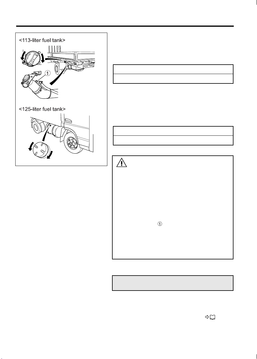
• 113-liter fuel tank
<FE>
The fuel tank is at the rear of the vehicle. To open
the fuel tank cap, slowly turn it counterclockwise. To
close the cap, turn it clockwise until you hear a click.
Fuel tank capacity
113 liters (29.8 gallons)
• 125-liter fuel tank
<FG>
The fuel tank is on the right-hand side of the vehicle. To open the cap, slowly turn it counterclockwise. To close the cap, turn it fully clockwise.
Fuel tank capacity
125 liters (33 gallons)
Z21324
WARNING
• When filling the fuel tank using a gun-type
fuel pump, do not continue pumping after
the pump automatically stops. (The tank is
full at this point.) When filling the fuel tank
using any other method, stop as soon as
the surface of the fuel becomes visible
through the opening of the fuel filler. If you
supply so much fuel that it comes up to
the opening, fuel may leak though the
check valve when the vehicle starts
moving and when it stops moving. If fuel
leaks, carefully wipe it all up to prevent the
risk of fire.
• If the pointer of the fuel gauge is above the
“F” mark, do not add the fuel any more.
DEF (Diesel exhaust fluid)
DEF is injected into the exhaust gas inside the muffler in order to break down NOx (oxides of nitrogen)
in the exhaust gas into water and nitrogen, and thus
reduces the amount of NOx. P. 5-48
Page 16
1-9
WARNING
DEF is a colorless, transparent, odorless and
harmless water solution (urea 32.5%, water
67.5%; Freezing temperature -11°C (12°F)), so
no problem will occur if you get it on your
skin. However, some persons with delicate
skin may in very rare cases get a rash, so
carry out the following procedure.
• If DEF gets on your skin, wash it off with
water. If there is any change in your skin or
it is painful, promptly see a doctor to
receive treatment.
• In the event that you accidentally ingest
DEF, drink one to two cupfuls of water or
milk, and promptly see a doctor to receive
treatment.
• If DEF gets into your eyes, immediately
wash your eyes with a copious amount of
water, then see a doctor to receive treatment.
1DEF used
Be sure to use DEF that conforms to ISO 22241.
ISO: International Organization for Standardization.
CAUTION
Do not carry out the following when using DEF
because this may cause damage to the
BlueTec
®
exhaust gas aftertreatment.
• Do not dilute the DEF.
• Do not mix the DEF with another reagent.
• Do not use DEF that does not conform to ISO
22241.
2Replenishing DEF
WARNING
Do not pour anything other than DEF into the
DEF tank. Particularly, never pour diesel fuel
or gasoline into the DEF tank, because this
may cause a fire or damage the BlueTec
exhaust gas aftertreatment.
If you accidentally fill the DEF tank with any
fluid other than DEF, immediately turn the
starter switch to the “LOCK” position, and
contact an authorized dealer to have the
incorrectly added fluid drained off and the
vehicle inspected.
®
Page 17
1-10 Recommendation to drivers
Z20976
CAUTION
Do not rest your foot on the DEF tank or step on
it, because this may damage the tank and/or the
sensors on it.
NOTE:
• Replenish the DEF well before it is used up.
• It is recommended that you obtain portable DEF
for use in the event that the DEF tank becomes
empty.
• You can obtain DEF at any of the following
places:
• Authorized dealer
• Authorized Parts and Service Center (PSC)
• Old World Industries distributor
• Exxon Mobil service station
DEF tank capacity 12 liters (3 gallon)
1. Turn the starter switch to the “LOCK” position to
stop the engine.
2. Wipe away dirt, mud, or other contamination in
the vicinity of the replenishment port.
3. Turn the cap counterclockwise and remove it.
4. While observing the level gauge , replenish
the DEF to the FULL line on the tank.
Z20977
CAUTION
• Do not use a steel container to hold DEF.
DEF reacts with steel and produces a corrosive material. If the tank is refilled with DEF
containing this corrosive material, the
BlueTec
damaged.
• Containers and appliances used to handle
DEF must not have been used for other purposes. Impurities that may remain in them
could adversely affect the quality of DEF and
prevent the engine from starting.
5. Install the cap securely by turning it clockwise.
NOTE:
If you spill the DEF during replenishment, wipe it
away with a cloth, or the like, and then wash the
area with water.
6. If the DEF tank becomes empty, a driving
restriction automatically engages, locking the
gear in first or reverse, so the vehicle can be
driven only slowly.
®
exhaust gas aftertreatment will be
Page 18
Z22085
1-11
3 Method for canceling the driving restric-
tion that has engaged due to an empty
DEF tank
If the DEF tank becomes empty, a driving restriction
automatically engages, locking the gear in first or
reverse, so the vehicle can be driven only slowly.
In the event of a driving restriction, replenish the
DEF and then disengage the restriction as follows.
1. After refilling the tank with DEF, turn the starter
switch from “LOCK” to “ON”.
2. Wait until the following changes in state have
completed.
• The warning lamp and DEF level warn-
ing lamp go out.
• The DEF level indicator lamp stops flash-
ing.
• The buzzer stops sounding.
Do not turn the starter switch to the “ACC” or
“LOCK” position before all the above changes
have completed.
NOTE:
• It may take a while after placing the starter
switch to “ON” for the warning lamp to go out
and for the buzzer to stop sounding.
• If the DEF tank becomes empty in cold weather,
perform the driving restriction canceling procedure immediately after refilling the tank with
DEF.
4 Storing the DEF
Seal the DEF container, and store it indoors in a
well-ventilated place away from direct sunlight.
The temperature of the storage place should be
between –5°C (23°F) and 25°C (77°F).
WARNING
Do not store DEF in a high temperature location.
If the temperature is high, DEF may release
ammonia, which is toxic. When storing the
container, seal it. Also, open it outdoors in a
well-ventilated area. If a pungent odor is
emitted from the container, do not carelessly
go near it.
Page 19

1-12 Recommendation to drivers
NOTE:
• You can use frozen DEF after allowing it to thaw,
without loss of quality.
• If you seal the container so as to prevent the
water from evaporating, the quality of the DEF
will not change.
• Although DEF is a non-flammable liquid, it may
emit a pungent odor if it is heated due to a fire,
for example. In the event that a fire breaks out,
promptly move the container to a safe place.
• It is strongly recommended to store or carry
DEF in the original container in which it was
sold. If unavoidable, you can also use a polypropylene tank usually used for drinking water or
the like instead, after thoroughly cleaning the
inside with DEF and making sure that it contains
absolutely no water or other impurities.
CAUTION
Do not store DEF in a non-specified container. If
DEF is stored in a steel container and then used
for replenishing, corrosive material produced
by chemical reactions will damage the BlueTec
exhaust gas aftertreatment.
®
• DEF must be handled as industrial waste when
discarding it.
CAUTION
Do not discard DEF in a lake or marsh, in the
sea, or in a river because this may cause environmental destruction.
Page 20
1-13
4000 km
(2500 miles)
Z18524
Z21323
Handling of the new vehicle
The way the vehicle is handled when new greatly
affects its subsequent performance and service life.
Observe the following precautions when handling
the new vehicle.
1 Maintenance
The “first maintenance at 4,000 km (2,500 miles)” is
very important for extending the service life of your
vehicle. We strongly recommend that you have this
inspection carried out by an authorized dealer. Be
sure to give the dealer this manual at that time.
2 Maximum engine speed during run-in
period
To avoid overburdening a new engine, limit engine
RPM to that indicated below for the first 1,000 km
(600 miles).
Then, run in your vehicle step by step at various
speeds, beginning with low gears.
Maximum engine RPM during run-in period
2,800 rpm
Page 21

1-14 Recommendation to drivers
Reporting safety defects
If you believe that your vehicle has a defect that
could cause a crash or could cause injury or death,
you should immediately inform both the National
Highway Traffic Safety Administration (NHTSA) and
the Mitsubishi Fuso Truck of America, Inc. (MFTA).
If NHTSA receives similar complaints, it may open
an investigation, and if it finds that a safety defect
exists in a group of vehicles, it may order a recall
and remedy campaign. However, NHTSA cannot
become involved in individual problems between
you, your dealer, or MFTA.
To contact NHTSA, you may either call the Vehicle
Safety Hotline at 1-888-327-4236 (TTY: 1-800-424-
9153) or write to: Administrator, National Highway
Traffic Safety Administration, 400 Seventh Street,
S.W., Washington, DC 20590.
You can also obtain other information about motor
vehicle safety from the Vehicle Safety Hotline.
For further information, please visit the following
NHTSA website:
http://www.safercar.gov
Obtaining service
At Mitsubishi Fuso Truck of America, Inc. (MFTA),
we are proud of the quality and workmanship that is
built into every MFTA Truck. We are equally proud
of our corporate commitment to promote the highest
possible degree of customer satisfaction with our
products and services.
Today’s trucks are extremely complex and are comprised of an enormous number of individual parts.
Occasionally, a failure of one of these parts may
occur. Should you experience such a failure, we are
confident that you will find an Authorized Dealer
prepared to provide you with high quality service.
Every Authorized Dealer has trained personnel,
plus the tools and equipment necessary to provide
for your various service needs. In the event that a
problem arises, we ask you to follow the procedure
outlined as follows, and in the sequence listed:
Page 22

1-15
STEP 1: Contact your Nearest Authorized Dealer
This is the most direct and expedient way to obtain
service. Each Authorized Dealer has the ultimate
responsibility for providing the services and repairs
you may need. We recommend that you contact the
Service Manager of your nearest Authorized Dealer
for assistance. In the event that you feel additional
assistance is required, ask to speak to the General
Manager of the Authorized Dealer.
STEP 2: Contact MFTA
After the completion of Step 1, and in the event that
your nearest Authorized Dealer has been unable to
satisfactorily resolve the problem, please contact
MFTA’s Customer Service Representative at 1-877-
711-0707.
Please be prepared to provide the following information when you call:
• Your Name, Company Name, Address, Tele-
phone Number
• Vehicle Model
• Vehicle Model Year
• Vehicle Identification Number
• Mileage
• Name of Dealer contacted under Step 1, if appli-
cable
• Details of the Complaint/Comment
You also may correspond with the Customer Service Representative in writing, addressed to:
MITSUBISHI FUSO TRUCK OF AMERICA, INC.
CUSTOMER SERVICE REPRESENTATIVE
2015 CENTER SQUARE RD.
LOGAN TOWNSHIP, NJ 08085
Page 23

Page 24

2-1
2. Warning labels
Labels inside the cab ......................................................................................................... 2-3
Exterior labels .................................................................................................................... 2-5
Page 25

2-2 Warning labels
• The caution and warning labels show important
information. Be sure to read them before using
the vehicle.
• If any label has peeled so it is difficult to read, is
scratched or otherwise damaged, or has peeled
off completely, please inform an authorized
dealer. The warning and caution labels apply
only to the vehicle itself, not to any equipment
mounted on the vehicle. For information on caution and warning labels that apply to equipment
mounted on the vehicle, please refer to the
Owner’s Manual supplied by the manufacturer
of the equipment.
• The locations of these labels and the informa-
tion on them may vary with the vehicle model.
Check the information on each label on your
vehicle.
Page 26
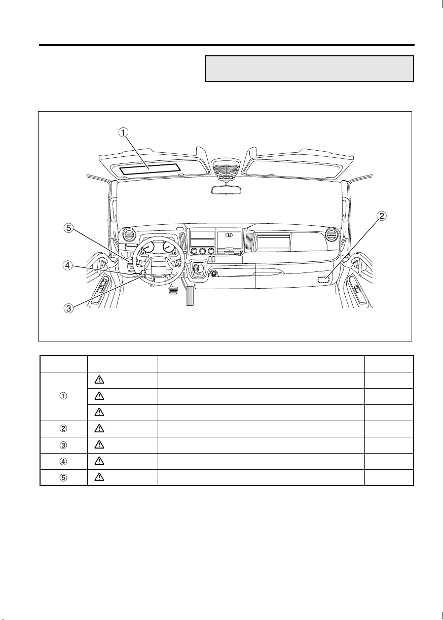
Labels inside the cab
1 Around the driver’s seat
2-3
Z21445
Location Category Information Ref. page
WARNING High temperatures of exhaust system components 5-50
WARNING Handling of DPF system with regeneration control 5-50
WARNING Handling of DEF 1-8
WARNING Use of specified fuses 13-10
WARNING Engine oil level check 12-23
WARNING Fuel to use 1-5
WARNING DPF indicator lamp 5-50
Page 27
2-4 Warning labels
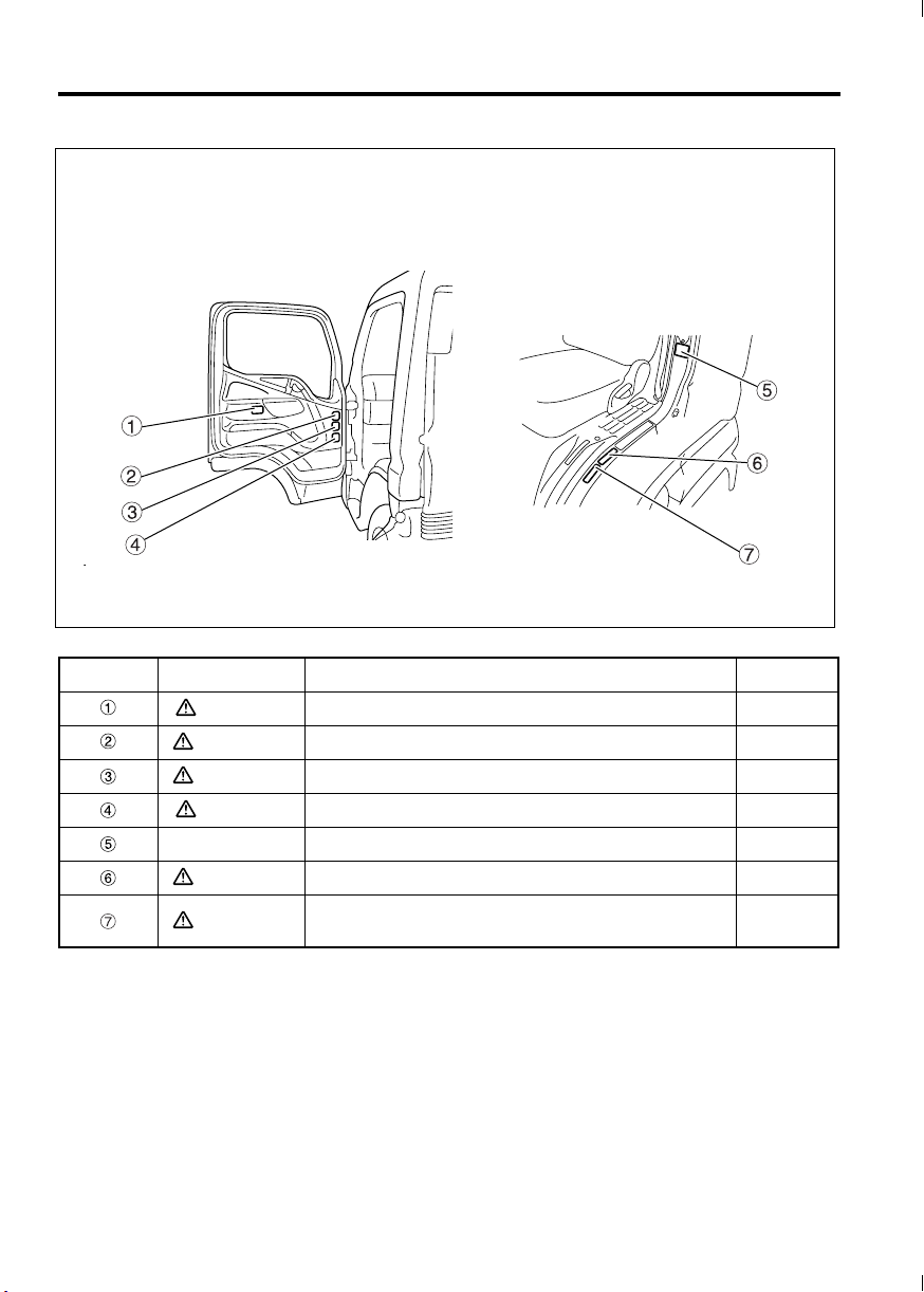
2 On driver’s door and door pillar
Z21446
Location Category Information Ref. page
CAUTION Handling of PTO <option> 5-45
WARNING Handling of DUONIC
WARNING 4WD <FG> 8-1
CAUTION Towing precautions 13-32
Standard value Tire pressure 12-66
WARNING 113-liter fuel tank refilling precaution <FE> 1-5
WARNING
Precautions for vehicles with limited slip differential
<FE: option; FG: standard>
TM
5-20
12-69
Page 28
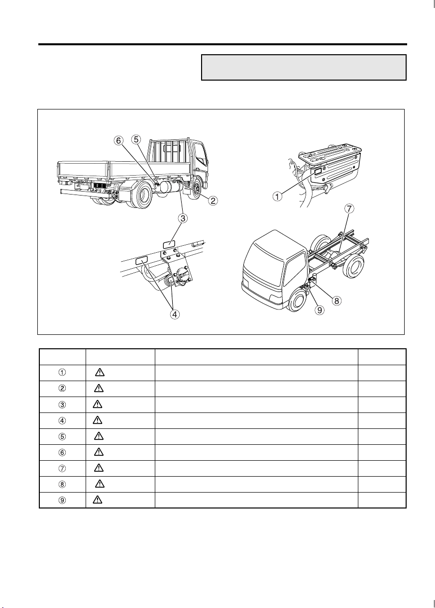
Exterior labels
1 On frame and exterior equipment
2-5
Z21448
Location Category Information Ref. page
DANGER High temperatures of exhaust system components 5-50
CAUTION Use of diesel fuel <FG> 1-5
WARNING Fuel to use 1-5
WARNING 113-liter fuel tank refilling precautions <FE> 1-5
CAUTION Prohibition against standing on DEF tank 1-8
CAUTION Use of DEF 1-8
CAUTION Oil to use for limited slip differential <option> 12-33
DANGER Precautions when handling the battery 12-82
WARNING Use of specified fuses 13-10
Page 29
2-6 Warning labels
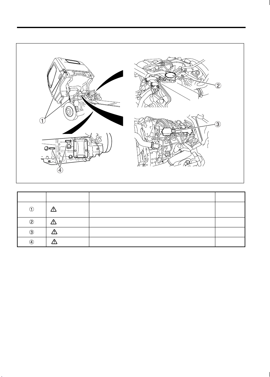
2 On cab outside and engine
Z21197
Location Category Information Ref. page
WARNING
WARNING Handling of pressure cap 12-56
CAUTION Inspection and replacement of engine oil 12-23
CAUTION Oil to use for clutch and transmission 12-28
Handling of cab tilt function (Vehicles other than
Crew-cab models)
12-6
Page 30

3-1
3. Opening and closing
Starter key .......................................................................................................................... 3-2
Engine immobilizer (theft prevention device) ..................................................................... 3-3
Doors ................................................................................................................................. 3-6
Central door locks .............................................................................................................. 3-8
Keyless entry system ......................................................................................................... 3-9
Entering and leaving the vehicle ...................................................................................... 3-13
Door window glass ........................................................................................................... 3-15
Page 31

3-2 Opening and closing
Z20927
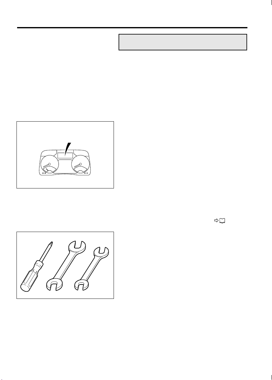
Starter key
• Your vehicle comes with a two-piece starter key
set .
• The starter key can be used to start and stop the
engine and lock and unlock the doors.
• Be sure to remove the number plate and keep
it in a safe place. You can purchase more starter
keys if you inform an authorized dealer of this
number.
• The starter key incorporates an engine immobi-
lizer function (theft prevention function). For the
engine immobilizer, refer to the next page.
P. 3 - 3
NOTE:
• The engine cannot be started unless you use an
immobilizer starter key that has been registered
to your vehicle’s immobilizer system.
• Do not store the engine immobilizer starter key
near a magnet of any other source of magnetism.
Page 32

Z21327
3-3
Engine immobilizer
(theft prevention device)
1 Engine immobilizer
NOTE:
The immobilizer complies with part 15 of the FCC
Rules. Operation is subject to the following two conditions:
(1) The immobilizer may not cause harmful inter-
ference.
(2) The immobilizer must accept any interference
received, including interference that may
cause undesired operation.
Changes or modifications not expressly approved
by the party responsible for compliance could void
the user’s authority to operate the equipment.
• The engine immobilizer is a theft prevention
device. It prevents the engine from being started
unless an engine immobilizer starter key that
has been registered to it is used.
• The engine immobilizer automatically starts
operating as soon as the starter switch is turned
to “ACC” or “LOCK”. Once the engine immobilizer is activated, it prevents the engine from
being started.
• The engine immobilizer starter key sends a sig-
nal to the vehicle, thereby canceling the engine
immobilizer such that the engine can be started.
NOTE:
In the circumstances detailed below, it is possible
that the vehicle cannot receive a signal from the
immobilizer starter key, meaning that the engine
cannot be started, even if the starter switch is
turned to the ‘‘START’’ position. If this happens,
remove any keys and other metallic objects that are
touching the immobilizer starter key, return the
starter switch to the ‘‘ACC’’ or ‘‘LOCK’’ position, and
try starting the engine again.
If you still cannot start the engine, have the vehicle
inspected at an authorized dealer.
Page 33

3-4 Opening and closing
• A metallic ring is on top of the handle of the
engine immobilizer starter key.
Z20929
• The handle of the engine immobilizer starter key
is in contact with a metallic part of another key.
Z20930
• The engine immobilizer starter key is placed on
top of or near to another vehicle’s engine immobilizer starter key.
• A key holder that emits radio waves or the
remote control switch of the keyless entry system is placed on top of or near the engine immobilizer starter key.
• A card with an embedded IC chip or a mobile
phone is held together with the engine immobilizer starter key.
Z20931
Page 34

3-5
The engine immobilizer starter key is an electronic
device containing a signal transmitter. Bear in mind
the following cautions:
• Do not bend the engine immobilizer starter key
or subject it to strong shocks.
• Do not leave the engine immobilizer starter key
in any part of the cab where it could be exposed
to direct sunlight and get extremely hot (60°C
(140°F) or higher).
•
Do not store the engine immobilizer starter key
near a magnet or any other source of magnetism.
• Do not disassemble or modify the engine immo-
bilizer starter key.
• Keep magnetic keyrings and other magnetic
items away from the engine immobilizer starter
key.
• Do not place the engine immobilizer starter key
near an audio player, personal computer, television set, or other device that is a source of magnetism.
• Do not clean the engine immobilizer starter key
using an ultrasonic cleaner.
In the event that you lose an engine immobilizer
starter key or wish to have a new one made, contact
an authorized dealer. (A maximum of six engine
immobilizer starter keys can be registered with a single vehicle.) You will need to take to the authorized
dealer all the engine immobilizer starter keys that
you have at the time.
Please note the following regarding registration of
starter keys:
• When having the registration of a starter key
deleted by an authorized dealer, also take to the
dealer all the starter keys for which you do not
wish to delete the registration.
• If you lose all of the starter keys, additional reg-
istration or deletion of registration of starter keys
is not possible, and you must then purchase a
new immobilizer control unit and a new starter
key.
Page 35

3-6 Opening and closing
Doors
WARNING
• To help prevent accidents, always check
for vehicles and pedestrians approaching
from behind before opening the doors.
• Driving with a door ajar can be very dan-
gerous. Make sure the doors are completely closed before starting.
• Exercise caution when opening a door in
strong wind. Otherwise, the wind could
catch the door and suddenly blow it open.
• Exercise caution when opening a door on
a downward slope. Otherwise, the inclination of the vehicle could cause the door to
suddenly fall open.
• When leaving the vehicle, take with you
any children or pets who was riding in the
cab. Never leave children or pets in the
cab. A child left in the cab could interfere
with the vehicle, causing it to move or
catch fire. Also, the cab gets extremely hot
in sunshine and in hot weather so a child
left in the cab could suffer heatstroke.
• When closing a door, be careful not to trap
your hand or anything else.
CAUTION
• Only open or close a door slowly without
applying undue force; otherwise the door
components could be damaged.
• Do not swing on or hang anything heavy on
any of the doors. Doing so could damage the
door components.
Page 36

Z21328
3-7
1 From the outside
•
To open, pull the outer handle toward you.
• Use the starter key to lock or unlock the door.
• It is possible to lock each door without using the
starter key. With the driver’s door or assistant
driver’s door, push the lock knob toward the
front of the vehicle then pull the outer handle
and keep it pulled as you close the door. With a
rear door, push the lock knob down then pull
the outer handle and keep it pulled as you close
the door.
NOTE:
• Locking the driver’s door using the starter key or
lock knob also causes the assistant driver’s door
and the rear doors (Crew-cab model vehicles) to
automatically lock.
On the other hand, unlocking the driver’s door
using the starter key or lock knob unlocks only
the driver’s door.
• When you leave your vehicle, be sure to remove
the starter key from the starter switch to prevent
theft.
• Be careful not to lock the doors with the starter
key inside the vehicle.
Z10731
Page 37

3-8 Opening and closing
Z10732
2 From the inside
•
To close, use the door waist bar . Close the
door completely.
• To lock the driver’s door or assistant driver’s
door, push the lock knob toward the front of
the vehicle. To lock a rear door, push the lock
knob down.
• To unlock and open the driver’s door or assist-
ant driver’s door, push the lock knob toward the
rear of the vehicle then pull the inner handle .
To unlock and open a rear door, pull up the lock
knob then pull the inner handle .
CAUTION
Closing the door by pulling any part other than
the door waist bar could damage the door
mechanism.
Central door locks
Z21331
• When the side of the switch is pressed, all
doors are locked. When the side of the
switch is pressed, all doors are unlocked.
• When the lock knob on the driver’s door is
pushed forward, the assistant driver’s door and
the rear doors (Crew-cab model vehicles) are
also automatically locked. If the lock knob on
any door is subsequently pushed rearward, only
that door is unlocked.
• When the driver’s door is locked from outside
using the starter key, the assistant driver’s door
and the rear doors (Crew-cab model vehicles)
are also automatically locked. If the starter key
is subsequently used to unlock any door, all the
doors except that door remain locked.
Page 38

3-9
Keyless entry system
1 The Grant of Equipment Authorization certificate for wireless transmitter
(remote control switch)
1. FCC ID: OBIH7079TX
2. This device complies with Part 15 of the FCC Rules. Operation is subject to the following
two conditions:
• This device may not cause harmful interference.
• This device must accept any interference received, including interference that may
cause undesired operation.
3. Changes or modifications not expressly approved by the party responsible for compliance
could void the user’s authority to operate the equipment.
Page 39

3-10 Opening and closing
Z21332
2 Keyless entry system
The keyless entry system allows you to lock/unlock
the driver’s door, assistant driver’s door and rear
doors (Crew-cab model vehicles) by operating the
remote control switch .
WARNING
If you carry the keyless entry remote control
switch with you when traveling on an airplane, avoid pressing any button on the
switch. If you keep the switch in a suit pocket
or somewhere like a bag, prevent the switch
buttons from being accidentally pressed,
since the radio-wave signals emitted from the
switch could interfere with normal operation
of the airplane.
CAUTION
• Do not expose the remote control switch to
water, disassemble it, or apply shock by
dropping it.
• Do not leave the remote control switch in a
place that is exposed to direct sunlight or
where the temperature rises to 60°C/140°F or
above. Doing so will shorten the life or cause
failure of the remote control switch.
• Do not remove the cover from the remote
control switch unless you replace the battery. Removing it for no reason could lead to
a remote control switch malfunction.
3 How to operate the remote control
switch
Point the remote control switch toward the cen-
•
ter of the cabin.
• Operate the remote control switch within 3 m
(9.8 ft.) from the center of the cabin.
• Press the button to lock all doors.
• Press the button once to unlock the
driver’s door. You can unlock the assistant
driver’s door and rear doors (Crew-cab model
vehicles) if you press the button one more
time within 5 seconds.
NOTE:
The assistant driver’s door and rear doors (Crewcab model vehicles) do not unlock if you press the
button more than 5 seconds after unlocking
the driver’s door.
Page 40

Z11389
3-11
• When you press the buttons, be sure to press
them for at least one second. If a button does
not work after one press, press the button again
after one or two seconds.
• After locking the doors with the remote control
switch, always check that the doors are locked
by lifting the outside handle of a door.
• You can check the locking/unlocking of the
doors by the flashing of the hazard lamps and
the room lamp. Leave the switch of the room
lamp “•” (in the center “•” position).
When the doors are locked, the room lamp and
the hazard lamps flash twice.
When the doors are unlocked, the hazard lamps
flash once and the room lamp lights up for about
10 seconds.
• If you do not open a door within 30 seconds
after unlocking with the remote control switch,
the doors will automatically be locked again.
NOTE:
• The range in which you can operate the remote
control varies somewhat depending on the surroundings, such as proximity to a TV tower,
power station, broadcasting station, etc.
• If you lose the remote control switch or the
switch does not work, please contact an authorized dealer. The dealer will produce two new
spare remote control switches for you.
The remote control switch does not work under the
following conditions:
• A door is open or incompletely closed.
• The starter key is in the starter switch.
4 Replacing the remote control switch battery
The battery may have run down if the remote control switch does not lock or unlock the doors upon
pressing the corresponding button. Replacing the
battery will solve the problem.
WARNING
• Keep the batteries out of the reach of chil-
dren. If a child swallows a battery, visit a
doctor immediately.
• Do not disassemble, heat or drop the bat-
tery in water. Doing so could cause a fire
or explosion.
Page 41

3-12 Opening and closing
CAUTION
• Use the designated standard type of battery.
If the battery is replaced with an incorrect
type, the battery could explode.
• Attach the battery with the “+” mark facing
upward.
• Do not use a metal tool such as tweezers to
replace the battery. Doing so could cause a
short circuit.
• Dispose of used batteries in accordance with
local regulations. Inconsiderate disposal
could adversely affect the environment. For
disposal, wrap the battery with tape, vinyl
sheet, etc. for insulation so that the battery
cannot contact other metal objects or be
exposed to water.
• Do not expose the inside of the remote con-
trol switch to water, and keep it away from
dirt and dust. Otherwise, the switch could
fail.
Designated battery Quantity
Lithium battery CR2032 1
Z20939
Z20940
1. Use a crosshead screwdriver to turn the
screw and remove the cover .
2. Place a new battery with the “+” mark facing
upward.
3. Reattach the cover and the screw.
4. Operate the switch and check that the remote
control works.
Page 42

3-13
Entering and leaving the vehicle
WARNING
• Always use the step to climb into or down
from the vehicle. Never put your foot on
the wheel or tire since it could easily slip
off.
• The step can become slippery in rain or
snow. Firmly hold the grip while climbing
into or down from the vehicle. Holding the
grip is particularly important when snow
has settled and frozen on the step.
• If the soles of your shoes are oily or
greasy, you could slip when climbing
down from the vehicle or when operating
the brake or clutch pedal.
Wipe any oil and grease off the soles of
your shoes before entering or leaving the
vehicle.
• Do not hold luggage or other items in your
hands when entering or leaving the vehicle since this can be dangerous.
• Do not jump down from the vehicle. Jump-
ing down from the vehicle could cause you
to fall or sustain an injury.
• Take care when entering or leaving the
vehicle on a slope or in a strong wind
since the door could open or close suddenly.
Page 43

3-14 Opening and closing
Z21333
CAUTION
• Climb into and out of the cab by holding only
the grip. If you hold onto any other parts of
the vehicle, they could break or fail.
• When entering or leaving an FG model truck,
do not place your feet or hands on the fender
. The fender could suffer damage. Also, the
fender can be dangerously slippery.
When climbing into and out of the cab, support your
body by at least three points at a time by firmly gripping the handle and fully placing your feet on the
steps . If you place your hand on the fender, put it
on the non-slip section .
Page 44

3-15
Door window glass
WARNING
Do not allow a child to put its hands or head
out of a window. The child’s head or hands
could hit an object outside the vehicle, and
the child could be seriously injured in the
event of hard braking.
1 Power window switches
WARNING
• Always make sure that no one has their
head or hands out of the window when
closing it. A body part could be injured if
caught in a closing window.
Never allow a child to open or close the
window.
• When a child is in the cab, be sure to press
the power window lock switch to prevent
the child from opening and closing the
assistant driver’s window. Otherwise, the
child may accidentally operate the power
window switch and get its hands or head
trapped.
Z21334
The power window switches function only when the
starter switch is in the “ON” position.
On the driver’s door, there are two switches: switch
for controlling the driver’s window and switch
for controlling the assistant driver’s window.
The switch for the driver’s window has an auto function for fully opening or fully closing the window with
a single touch of the switch.
Switch for assistant driver’s window.
Gently press the switch to open the window. The
window will move only while you are pressing
the switch. It will stop when you release the
switch.
Gently pull the switch to close the window. The
window will move only while you are pulling the
switch. It will stop when you release the switch.
To fully open the driver’s window with a single
touch of the switch, press the switch firmly. If
you wish to stop the window part-way, give the
switch a gentle pull.
Page 45

3-16 Opening and closing
To fully close the driver’s window with a single
touch of the switch, pull the switch firmly. If you
wish to stop the window part-way, give the
switch a gentle push.
CAUTION
Do not keep any door or window open in rainy
weather, and be careful not to spill a drink on
any of the window switches. If water or any
other liquid gets on a window switch, it can
cause a malfunction.
NOTE:
In cold weather, the auto function may not work
temporarily. In this event, keep pushing or pulling
the switch to fully open or close the window.
2 Window regulator handle
<Crew-cab models>
Turn the window regulator handle to open or
close the window.
Open
Close
Z21335
Page 46

4-1
4. Seat and steering wheel adjustments
Seats .................................................................................................................................. 4-2
Seat belts ........................................................................................................................... 4-5
Steering wheel ................................................................................................................... 4-9
Page 47

4-2 Seat and steering wheel adjustments
Seats
WARNING
• Adjusting the seat while the vehicle is in
motion is dangerous as the seat may move
more than you intend. Be sure to stop the
vehicle and set the parking brake before
performing any adjustment of the seat.
• After you have adjusted the seat, gently
move or rock the seat to ensure that it is
locked in the desired position.
• When adjusting the seat, keep your hands
away from the bottom of the seat and from
moving parts of the seat. Otherwise, you
could suffer an injury by getting your
hands and fingers trapped.
• When adjusting the angle of the seatback,
keep your back or hand pressed against it.
Otherwise, the seatback could suddenly
return to its original position and injure
you by hitting your face or other body
parts.
Z11863
1 Driver’s seat
1.1 Correct driving position
• Before driving the vehicle, adjust the seat with
reference to the following points:
Your back must touch the seatback, and you
must be able to see the warning lamps and
gauges.
You must be able to reach and firmly press
the pedals.
You must be able to operate the steering
wheel and switches with ease.
You must be able to operate the shift lever
with ease.
You must be able to fasten the seat belt correctly.
• Adjust the steering wheel to a position at which
you can operate it comfortably with your arms
slightly bent.
Page 48

Z21336
4-3
1.2 Making adjustments
• Slide seat forward or backward while holding
slide adjustment lever raised. After making
the adjustment, release the lever and move the
seat back and forth slightly to lock it in position.
• To adjust the angle of the seatback , raise
reclining lever .
• Lower the armrest to use it.
• Lumbar support lever <option>
Pull the lever to adjust the hardness of the
lumbar support in the seatback as desired.
2 Assistant driver’s seat
Assistant driver’s seat
Center seat
It is possible to tip the seatback fully forward. With
the lever pulled, grasp the seatback at the top
and tip it forward.
After returning the seatback to its original position,
gently rock it to make sure it is locked in place.
Z21337
NOTE:
If the lever is difficult to move, pull it while pushing the top of the seatback rearward. Then you will
be able to pull the lever easily.
Page 49

4-4 Seat and steering wheel adjustments
Z12099
3 Rear seat – Crew-cab models
Storage compartments are located under the rear
seat. The rear seat can be folded up for access to
them. When you wish to stow or remove something
from these compartments, release the clamps at
the base of the seat and raise the seat cushion .
To retain the seat cushion, use the retaining bands
that are attached to the seatback. Fit the loop
at the end of each retaining band over the corresponding hook on the seat cushion.
After using this storage, return the rear seat to the
original position and lock it by fully fastening the
clamps.
Page 50

Z21338
4-5
Seat belts
• To help prevent injury in the event of a sudden
stop or accident, the driver and all passengers
must wear their seat belts correctly.
• When wearing your seat belt, sit back in your
seat with your back straight. If a seat belt is used
incorrectly, its effectiveness is greatly diminished and it could aggravate injuries in the event
of accident.
• For details of seat belt usage for children and
pregnant women, refer to “Children and babies”
and to “Pregnant women”. P. 4-8
WARNING
• Passengers must never be in the cargo
area while the vehicle is in motion. Unless
seated and properly belted up, the risk of
injury is greatly increased.
• Seat belts should be worn as low as possi-
ble over the hips. Wearing a seat belt
across the abdomen could be dangerous
since undue pressure would be placed on
internal organs in the event of a collision.
• Make sure that the seat belt is not twisted
when fastening it. A twisted seat belt could
be dangerous since its reduced width will
apply a larger force to a smaller part of
your body in the event of impact.
• Replace any seat belt that is cut or frayed,
or if its buckle does not work properly.
• Never use a single seat belt for more than
one person.
• It is dangerous to fasten or unfasten your
seat belt while driving since the momentary diversion of your attention could lead
to a serious accident. Always stop the
vehicle first.
• The left and right seats feature 3-point lap and
shoulder belts with Emergency Locking Retractor (ELR), while the middle seat features a 2point lap belt.
Page 51

4-6 Seat and steering wheel adjustments
Z10760
1 Lap and shoulder belts with ELR
NOTE:
It is not necessary to adjust the length of these seat
belts.
An ELR seat belt extends and retracts automatically
as its wearer moves but locks automatically for protection in the event of a sudden stop or shock.
The belt’s tightness should be adjusted automatically. If there is any looseness, lift the shoulder belt
gently and the mechanism will take up the slack.
With the belt properly tightened, the risk of it slipping off in a collision is reduced.
• Fastening
1. Hold tang and gently extend the belt. If the
belt locks or is difficult to extend, let it retract and
pull it gently again.
2. Take care that the belt does not become twisted.
Insert the tang into the buckle until you hear a
click.
3. Pull on the tang to confirm that it is locked in.
4. Adjust the belt so it is across your hips and
shoulder.
Z11726
Z01351
• Unfastening
1. Press the red button to unlock the buckle.
2. The belt automatically retracts when unlocked.
To prevent the tang causing damage or injury,
hold it while the belt retracts.
3. Adjust the tang stopper to locate the tang in
an easy-to-reach position and prevent it from
slipping.
Page 52

1.1 Seat belt anchor
<Driver’s seat>
WARNING
The shoulder belt can be dangerous if worn
across the neck. Adjust its position so that it
does not cross over the neck.
4-7
Z08772
Z20955
Adjust the seat belt anchor upward or downward
to ensure that the belt passes across your shoulder.
You will need to keep the lock button pulled while
moving the seat belt anchor downward. When the
seat belt anchor has reached the desired position,
release the lock button and jiggle the seat belt
anchor up and down to make sure it is locked in
place.
2Lap belt
•
Fastening
1. Take care that the belt does not become twisted.
Insert the tang into the buckle until you
hear a click.
2. Pull on the tang to confirm that it is locked in.
3. Adjust the belt so it is low across your hips.
4. To adjust the belt’s length, hold the tang at 90°
to the belt.
Pull the belt end to shorten the belt or the tang
to lengthen it.
To lengthen
To shorten
WARNING
For maximum protection in the event of an
accident, the belt must not be loose. A loose
belt could even aggravate injuries.
• Unfastening
1. Press the red button to unlock the buckle.
2. When the belt is not in use, insert its tang into
the buckle.
Page 53

4-8 Seat and steering wheel adjustments
3 Children and babies
•
When carrying children or babies, they must be
restrained properly to minimize the risk of injury
in the event of a sudden stop or accident. Never
allow children to stand or kneel on the seats. For
maximum safety, we recommend fitting and
using a restraint system that complies with Federal Motor Vehicle Safety Standards.
The use of child and/or baby restraint systems is
mandatory in some states. Please abide by your
state’s regulations.
• Older children may sit on the regular seats and
use the regular seat belts. However, make sure
that the shoulder belts do not cross their necks
or faces.
4 Pregnant women
Since a seat belt could exert undue pressure on the
abdomen in the event of an accident, pregnant
women should consult a doctor about the use of
seat belts before riding in the vehicle.
A pregnant woman should wear her seat belt as low
as possible across the hips, not across her abdomen.
5 Seat belt care
•
Periodically, check the action of the mechanical
parts such as the buckles, tangs, and emergency locking retractor (ELR) units. Check also
for any damage that could stop the seat belts
from functioning properly.
Replace seat belt unit if there is any malfunction
or damage.
• Replace any webbing that is cut, frayed, or oth-
erwise damaged.
• Replace any seat belt that has received a shock
due to a collision.
• Keep sharp or other potentially damaging
objects away from the seat belts, especially the
webbing.
• Keep the seat belts clean and dry. Use a mild
soap and lukewarm water to clean seat belts.
Such solvents as gasoline and thinner may seriously affect the strength of the webbing.
P. 1 2 - 9 3
• Never attempt to bleach or dye the seat belts, as
this could weaken them considerably.
• Do not attempt to remove the seat belts or dis-
assemble the ELR units.
Page 54

4-9
Steering wheel
WARNING
• After every adjustment, try to move the
steering wheel back and forth to make
sure that it is securely locked. Unless the
lever returns to its original position, the
steering wheel may move while the vehicle
is in motion and cause an accident.
• Make adjustments with the vehicle station-
ary. Adjusting the steering wheel while
driving is dangerous since it could detract
from your concentration or cause the
steering wheel to move more than desired.
The steering wheel can be adjusted to the preferred
height and tilted forward/backward. Adjust the
steering wheel as well as the seat to the best positions for easy safe driving.
• Pull the lock lever then adjust the steering
wheel to the height and angle that are most
comfortable for you.
• Push the lock lever back in to securely retain the
steering wheel.
Adjust
Retain
Z21339
Page 55

Page 56

5-1
5. Switches and controls
Arrangement of switches and controls ............................................................................... 5-2
Starter switch ..................................................................................................................... 5-3
Starting the engine ............................................................................................................. 5-5
Warming up the engine .................................................................................................... 5-10
Stopping the engine ......................................................................................................... 5-12
Pedals .............................................................................................................................. 5-14
Parking brake lever .......................................................................................................... 5-15
Combination switch .......................................................................................................... 5-16
TM
DUONIC
Cruise control ................................................................................................................... 5-36
Hazard warning lamp switch ............................................................................................ 5-42
Front fog lamp switch ...................................................................................................... 5-43
Van body dome light switch ............................................................................................. 5-43
Rearview mirrors .............................................................................................................. 5-43
Mirror heater switch ........................................................................................................ 5-44
Horn switch ...................................................................................................................... 5-45
Transmission PTO .......................................................................................................... 5-45
BlueTec
....................................................................................................................... 5-20
®
system ............................................................................................................. 5-48
Page 57

5-2 Switches and controls
Z21340
Arrangement of switches and
controls
Starter switch
Accelerator pedal
Brake pedal
Gearshift lever
Parking brake lever
Hazard warning lamp switch
Combination switch
(wiper and washer switch, exhaust brake switch
<option>)
Combination switch
(lighting switch, passing/dimmer switch, turn signal switch)
Front drive switch <FG> P. 8-3
ECO mode switch
DPF cleaning switch
Central door lock switch P. 3-8
Cruise control main switch
Cruise control SET/RESUME switch
Van body dome light switch
Mirror heater switch <option>
Power take-off switch <option>
Front fog lamp switch <option>
Page 58

5-3
Starter switch
1 Starter switch position
WARNING
Never turn the starter switch to any position
other than the “ON” position while driving
the vehicle. Turning the starter switch to the
“ACC” position would be dangerous because
the engine would stop and the following
problems would occur:
• The braking force is severely reduced.
• The power steering system would stop
working so the steering action would
become extremely heavy.
• The fuel injection system can malfunction.
• The electric circuits for the warning lamps
and meters would stop working, and elec-
tric parts could fail.
When the starter key is removed from the
starter switch, the steering wheel locks, making steering impossible.
CAUTION
• Do not turn the starter switch to the “START”
position while the engine is running. Doing
so could damage the starter.
• The starter key cannot be turned from the
“ACC” position to the “LOCK” position
unless it is pressed in. Do not attempt to turn
it by force. Keep the key pressed in while
turning it from the “ACC” position to the
“LOCK” position.
• If you park the vehicle over an extended
period of time, always remove the key from
the starter switch. Leaving the key in the
“LOCK”, “ON” or “ACC” position could run
down the battery.
• Avoid using the “ACC” position for long
periods, for example, for listening to the
radio, as the battery could be completely discharged.
Page 59

5-4 Switches and controls
Z21341
• LOCK
The starter key can be inserted and removed
in this position only. To place the key in the
“LOCK” position, turn it to the “ACC” position
then press it in. Keep it pressed in while turning
it to the “LOCK” position. When the key is
removed, the steering wheel locks.
The lighting switch, hazard warning lamps, interior lamp, horn, central door locks and turn signal lamps can be used.
• ACC
The engine is shut off or is not running in this
position.
The cigarette lighter can be used. Audio equipment (radio, etc.) installed and connected in the
approved manner can also be used.
• ON
The engine is running in this position.
All electrical circuits are operable.
• START
The engine is turned over and started in this
position.
Once the engine is running, release the key and
the switch will automatically return to the “ON”
position.
NOTE:
• Turn the key only after inserting it fully in the
starter switch.
• If you are unable to turn the key, gently turn the
steering wheel clockwise and counterclockwise
as you turn the key.
• The starter key can neither be turned to the
“LOCK” position nor pulled out unless the gearshift lever is in the “P” position.
2 Starter key reminder alarm
A buzzer sounds if you open the door with the
engine shut down and the key left in the starter
switch. Remove the starter key from the switch and
keep it with you whenever leaving the vehicle.
Page 60

Z11944
5-5
Starting the engine
WARNING
• Do not start or warm up the engine in a
garage or other closed area. When starting
the engine or entering or leaving a garage,
do not run the engine for longer than is
necessary as the accumulation of exhaust
gas in closed areas is very dangerous.
Exhaust emissions contain carbon monox-
ide (CO), which if breathed can cause
unconsciousness or death.
• If you smell exhaust gases inside the cab,
inspect the exhaust pipe and check
whether exhaust gases are leaking
through holes or cracks caused by corro-
sion or damage. If exhaust gases are leak-
ing, have the exhaust pipe inspected by an
authorized dealer.
If exhaust gases that have leaked from the
exhaust pipe come into the cab, ventilate
the cab with fresh air by opening the win-
dows fully or by opening the doors.
• Make sure that there are no flammables
under or behind the parked vehicle, espe-
cially close to the exhaust pipe. A fire
could be started by the heat from the
engine or exhaust pipe.
• When you start the engine, be sure to sit in
the correct position on the driver’s seat to
wait for the engine to warm up. If you are
leaning out of the door window or other-
wise incorrectly seated and the vehicle
suddenly moves, a serious accident could
occur.
• Get into the habit of always using the right
foot to depress the brake pedal. If you use
the left foot, the pedal-pressing action will
not be fully responsive, which could lead
to an accident especially in the case of
emergency braking. Before starting the
engine, depress the accelerator pedal and
brake pedal with your right foot to confirm
the locations of these pedals.
Page 61

5-6 Switches and controls
Z21530
CAUTION
• Do not try to push-start the engine. Push-
starting the engine is impossible for this
vehicle and could damage the transmission.
• Do not use ether or other vapor compound
type starting aids. Use of such fluid on this
engine could result in serious damage.
NOTE:
• After the engine has started, let it warm up for 1
to 2 minutes.
• Do not continue operating the starter for more
than 15 seconds as this could damage it or discharge the battery.
• If you operate the starter continuously for 10
seconds and the engine still does not start, turn
the starter switch to the “ACC” position and wait
about 30 seconds for the battery to recover
before performing the starting procedure again.
• On a vehicle that has not been operated for a
week or more, or after replacement of engine oil
or engine oil filter element, be sure to crank the
engine before starting it. P. 5 - 8
1 Pre-starting steps
1. Pull parking brake lever to fully apply the parking
brake.
2. Place the gearshift lever in the “P” position.
Make sure the gear position indicator displays
“P”.
NOTE:
Your vehicle’s engine cannot be started unless the
gearshift lever is in the “P” or “N” position. For
safety, we recommend starting the engine with the
gearshift lever in the “P” position. Use the “N” position only when absolutely necessary, for example, if
the engine stops while the vehicle is on a railroad
crossing.
Page 62

Z15222
Z21163
5-7
2 Starting procedure
1. Depress the brake pedal fully.
CAUTION
For safety, keep the brake pedal depressed until
the engine has started.
2. Turn the starter switch to the “ON” position.
3. Check whether the indicator lamp illuminates or not.
Z21164
Z21531
• When the indicator lamp does not illumi-
nate
While holding down the brake pedal, turn the
starter switch to the “START” position to start the
engine.
Page 63

5-8 Switches and controls
• When the indicator lamp illuminates
Wait until the indicator lamp goes out.
While holding down the brake pedal, turn the
starter switch to the “START” position to start the
engine.
NOTE:
If the engine is difficult to start after the indicator
lamp has gone out, there may be a problem with the
engine preheating system. Have the vehicle
inspected by an authorized dealer.
4. After the engine has started, let it warm up for 1
to 2 minutes. P. 5-10
Engine idling speed
650 rpm
3 Starting the engine when vehicle has
been parked over an extended period
When the vehicle is not used for a week or more or
when the engine oil and oil filter are replaced, the
engine becomes starved of oil. Before the engine is
started, therefore, it must be cranked in accordance
with the following procedure to distribute oil to its
various components.
Page 64

5-9
CAUTION
• To ensure maximum safety, be sure to pull
the parking brake lever fully to apply the
parking brake and block the wheels with
chocks thus preventing the vehicle from
accidentally moving.
• Performing the cranking is of essential
importance in terms of protecting the turbocharger.
1. Pull the parking brake lever to fully apply the
parking brake.
2. Place the gearshift lever in the “P” position.
3. Start the engine in the normal way. You do not
need to wait for indicator lamp to turn off.
4. Without depressing the accelerator pedal, place
the starter switch in the “START” position and
crank the engine for roughly 15 seconds.
If the engine starts, release the starter key and
do not depress the accelerator pedal for roughly
15 seconds.
4 Starting the engine with the cab tilted
When you need to start the engine with the cab
tilted for inspection or servicing purposes, be sure
to observe the following safety precautions:
Z21532
• Set the parking brake firmly and chock the
wheels.
• Make sure the gearshift lever is placed in the “P”
position and the gear position indicator shows
“P”.
• Make sure nobody is near the engine compart-
ment, then place the starter switch in the
“START” position to start the engine.
Page 65

5-10 Switches and controls
Z11944
Warming up the engine
Let the engine warm up for 1 to 2 minutes before
starting the vehicle.
WARNING
• Do not warm up the engine in a garage or
other closed area. When starting the
engine or entering or leaving a garage, do
not run the engine for longer than is necessary as the accumulation of exhaust gas
in closed areas is very dangerous.
Exhaust emissions contain carbon monoxide (CO), which if breathed can cause
unconsciousness or death.
• If you smell exhaust gases inside the cab,
inspect the exhaust pipe and check
whether exhaust gases are leaking
through holes or cracks caused by corrosion or damage. If exhaust gases are leaking, have the exhaust pipe inspected by an
authorized dealer.
If exhaust gases that have leaked from the
exhaust pipe come into the cab, ventilate
the cab with fresh air by opening the windows fully or by opening the doors.
• Make sure that there are no flammables
under or behind the parked vehicle, especially close to the exhaust pipe. A fire
could be started by the heat from the
engine or exhaust pipe.
CAUTION
Racing the engine immediately after it has
started causes excessive wear of cylinders and
pistons, leading to engine malfunction. This
also causes a fault in the turbocharger as the
turbocharger starts spinning at high speed
before engine oil is sufficiently distributed to its
shaft. Be sure to warm up the engine to operating temperature before full load operation
according to the procedures described here.
Page 66

5-11
NOTE:
• Idling the engine for long time wastes fuel, and
is therefore detrimental to environmental protection and resource conservation. So shut down
the engine whenever you leave the vehicle,
even for a short period.
If you start to drive immediately after starting the
engine (while the engine is still cold), you will
encounter the following problems:
• In a cold region, the extreme coldness of the
engine will cause poor ignition of fuel, making
the engine prone to knocking.
• You may encounter any or all of the following
conditions. They are due to the actions particular to the oxidation catalyst inside the muffler
and do not indicate any abnormalities.
• White smoke from the exhaust pipe when
setting the vehicle in motion after idling the
engine for a relatively long-time or when
accelerating the vehicle.
• White smoke from the exhaust pipe when
the vehicle starts off immediately after the
engine is started.
• The exhaust smells irritating (with a vinegar-
like odor).
• In cold months, the engine may operate at an
idling speed higher than usual just after its start.
The engine speed, however, will drop to a normal speed as the coolant warms up.
• Warm up the engine sufficiently, otherwise gear
shifting may be sluggish.
Page 67

5-12 Switches and controls
Stopping the engine
WARNING
• Never allow the vehicle to coast with the
engine stopped as braking may be dangerously sluggish and extremely difficult
steering may result. This may also cause
trouble in the fuel injection system.
• The engine and exhaust pipe are extremely
hot just after stopping the vehicle. Avoid
parking the vehicle where the exhaust pipe
could set fire to materials such as dry
grass.
• Do not stop the engine for parking with the
steering wheel fully turned to either direction. This will cause the power steering
system pressure to drop, thus causing the
steering wheel to return rapidly, possibly
injuring you.
• Do not park on a slope. A vehicle parked
on a slope can move uncontrollably and
cause an accident.
If it is unavoidable to park the vehicle on a
slope, do the following: Firmly apply the
parking brake, place the gearshift lever in
the “P” position, chock the wheels, and
turn the steering wheel toward an obstruction (like a curb stone) for increased safety
in case the vehicle moves.
• Do not park the vehicle only with the gear-
shift lever placed in the “P” position;
always firmly engage the parking brake. If
you park the vehicle on a steep slope only
by placing the gearshift lever in the “P”
position without also engaging the parking
brake, the gearshift lever will become
extremely difficult to move or, in the worst
case, it may be impossible to release the
transmission from the locked state. If this
happens, shift the gearshift lever into the
“N” position and then, after making sure
the gear position indicator shows “N”,
move the lever to the “D” position.
Page 68
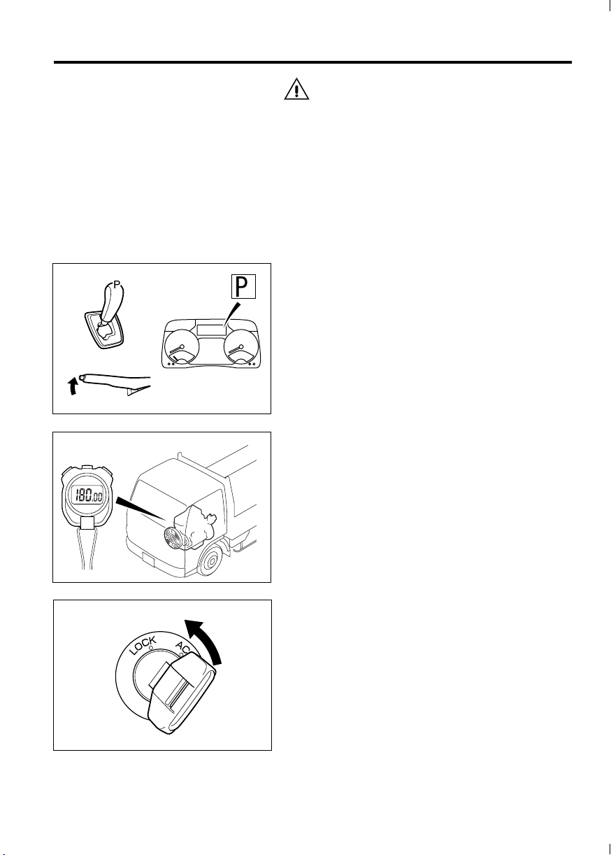
Z21530
5-13
CAUTION
• If you stop the engine immediately after
uphill or high-speed driving, the oil supplied
to the rotor shaft of the turbocharger will rise
to an abnormally high temperature and the
rotor shafts could seize up. To avoid this, run
the engine at idle for at least 3 minutes
instead of stopping it immediately.
• The engine should only be stopped from an
idle. Stopping it at a high RPM could result in
an engine malfunction.
1. Hold down the brake pedal and apply the parking brake.
2. Place the gearshift lever in the “P” position.
Make sure the gear position indicator shows “P”.
More than
3 minutes
3. Allow the engine to idle for more than 3 minutes
before stopping it.
When the vehicle is in motion, engine parts
become extremely hot. This is particularly true
during uphill or high-speed driving. Therefore,
let the engine cool down sufficiently by allowing
it to idle for a time before stopping it.
Z16069
4. Turn the starter switch to the “ACC” position to
stop the engine.
Z21168
Page 69

5-14 Switches and controls
Z21342
Pedals
Accelerator pedal
WARNING
If you use a floor mat, be sure to use a Mitsubishi Fuso genuine floor mat and lay it correctly. Do not lay the floor mat over the
accelerator pedal or accelerator pedal stopper. Do not lay a floor mat over another floor
mat. Failure to observe these instructions
would be dangerous because the accelerator
pedal could be prevented from returning
when released.
Racing the engine also increases fuel consumption.
NOTE:
Depressing the brake pedal while depressing the
accelerator pedal will increase safety, as this helps
reduce the engine power.
Brake pedal
WARNING
Do not allow empty beverage cans or other
objects to get under the brake pedal as they
may hinder the brake pedal operation, leading to an extremely dangerous situation.
Keep the floor clear of empty beverage cans
and other objects.
• If your vehicle is equipped with disc brakes and
you notice squealing during braking, the disc
brake pads have worn to the limit and must be
replaced. Have the vehicle inspected by an
authorized dealer.
• Use the brake pedal correctly. P. 7-8
Page 70

5-15
Parking brake lever
WARNING
• Do not use the parking brake when driv-
ing except in an emergency, like if the service brakes have failed. Such use of the
parking brake may make the vehicle spin
or, at worst, roll over. It may also cause
faults in vehicle components.
• Illumination of the warning lamp does
not necessarily indicate that the parking
brake has been fully activated. Be sure to
pull the lever all the way.
1 Using the parking brake lever
Parking
The parking brake is activated when the parking
brake lever is fully pulled up. The warning lamp
lights up simultaneously.
Releasing
Raise the lever slightly, press the end button , and
lower the lever with the button still pressed. Make
sure that the warning lamp goes out.
• When parking, please bear in mind the cautions
in “Parking”, chapter 7. P. 7-15
Z21343
2 Parking brake alarm
•
If you start the vehicle without releasing the parking brake and the vehicle moves at a speed of
12 km/h (7 mph) or higher, a buzzer will sound
(beeps intermittently) 3 seconds later to warn you.
• If the buzzer sounds, immediately stop the vehi-
cle in a safe place and then release the parking
brake.
CAUTION
• Before putting the vehicle in motion, com-
pletely release the parking brake lever and
check that the warning lamp is not illuminated. If you accidentally drove the vehicle
with the parking brake applied, the parking
brake would wear prematurely and overheat,
leading to reduced effectiveness and the risk
of a fire.
• When parking your vehicle on a slope, block
the wheels with chocks for added safety.
Page 71

5-16 Switches and controls
Z21344
Z21345
Combination switch
1 Arrangement of switches
Lighting switch
Passing/dimmer switch
Turn signal switch
Exhaust brake switch <option>
Wiper and washer switch
2 Lighting switch
CAUTION
Keeping the headlamps on for a long period
without the engine running can drain the battery, making the engine impossible to start.
The lighting switch can be used with the starter
switch in any position.
Turning the knob at the end of the lever controls the
illumination of lamps as follows:
Identification, clearance
and side marker,
OFF
position
position
position
parking, tail, license,
front fog <option> and
meter illumination lamps
Off On*
On On*
On On
Headlamps
*: Illuminated by daytime running light system
NOTE:
Even when the vehicle is operated with the lighting
switch in the “OFF” or position, the daytime
running light system causes the low-beam headlamps to be lit. (The headlamps are dimmer than
when activated using the lighting switch.) The
indicator lamp is also lit. When the parking brake is
applied or the engine is stopped, the headlamps
and the indicator lamp go off.
Page 72

Z21346
Z21347
5-17
3 Passing signal/dimmer switch
Passing signal
Pulling the lever up activates the high beams until
the lever is released. Use this to flash a signal when
overtaking another vehicle.
Dimmer
With the headlamps illuminated, pushing the lever
down activates the headlamp high beams and pulling it back to the original position reactivates the low
beams. When the high beams are on, indicator
lamp lights up.
4 Turn signal lamp switch
Turn signal
Moving the lever forward or backward activates the
corresponding turn signal causing it to flash. At the
same time, the corresponding indicator lamp or
flashes.
When the steering wheel is returned to the neutral
position after a right or left turn, the switch automatically moves back to the neutral position and the
lamp stops flashing. After making a moderate turn,
however, the switch will sometimes not return automatically. In this case, put the switch in the neutral
position by hand.
Lane changer
Lightly pushing the lever forward or backward
causes the corresponding turn signal lamp to flash
while the lever is held in this position.
5 Exhaust brake <Option>
WARNING
Using the exhaust brake on a wet, frozen,
snow-covered, or otherwise slippery road
surface when the vehicle is lightly loaded or
not loaded can cause the tires to slip on the
road surface, resulting in a skid. Do not use
the exhaust brake on slippery road surfaces.
The exhaust brake enhances engine braking. Use it
as an auxiliary braking means on downhill stretches
or during high-speed driving.
Page 73

5-18 Switches and controls
Z21348
NOTE:
• Do not keep the exhaust brake switch in the
activation position at all times. Keeping the
switch in the activation position worsens fuel
consumption, as doing so causes the exhaust
brake to work frequently and thus the vehicle to
decelerate and accelerate frequently.
Save fuel by using the exhaust brake switch
appropriately according to road and traffic conditions.
• The exhaust brake is activated when the auto-
matic DPF regeneration takes place during
parking. The indicator, however, is not illuminated.
• Activation and deactivation of exhaust
brake
Pushing the lever forward activates the exhaust
brake. While the exhaust brake is activated, the
indicator lamp stays illuminated.
Deactivated
Activated
The exhaust brake will be temporarily disabled in
the following conditions. Full functionality will be
returned when the original conditions have been
restored.
• The accelerator pedal is depressed.
• The gearshift lever is moved to “N”.
• The ABS is operating.
6 Wiper and washer switch
WARNING
In cold weather, warm the windshield with the
heater before operating the washer since
washer fluid could otherwise freeze onto the
windshield and obstruct your vision.
CAUTION
• Operating the wipers when the windshield is
dry damages the windshield glass. If the
glass is dry, be sure to squirt it with washer
fluid before operating the wipers.
• Check nearby conditions before operating
the washer switch. Washer fluid may splash
around in some circumstances.
Page 74

Z21349
5-19
• Do not operate the wipers when the rubber
parts of the wiper blades are frozen onto the
windshield or otherwise stuck to the windshield. The wiper blades could get damaged,
and the wiper motor could fail.
• When the wipers are not used for a long
time, dust, sand, and other substances can
collect between the wiper blades and windshield. Clean the wipers before using them.
Otherwise, the windshield may get
scratched.
• Operating the washer continuously for more
than 20 seconds or when there is no fluid in
the reservoir could burn out the washer
motor.
• Rotating the grip at the end of the lever activates
the windshield wipers in one of the following
three modes:
INT: Wipers operate intermittently. By operating
the interval control switch , the operating
interval of wipers can be varied between 3
and 12 seconds.
LO: Wipers operate at a slow speed.
HI: Wipers operate at a rapid speed.
MIST: The wipers operate once when you flip up
the lever toward you.
Replace the wiper blades if they start to work ineffectively. P. 12-80
CAUTION
Wiper blade rubber can deteriorate over time,
causing the wipers to work ineffectively and
possibly causing the windshield to be
scratched.
• Pressing the button sprays washer fluid onto the
windshield.
• Refill the washer fluid reservoir before it is
empty. P. 12-81
• If there is washer fluid in the reservoir but none
is sprayed when you operate the washer, the
nozzles may be blocked. Clean the nozzles
using a piece of thin wire. If fluid is still not
sprayed when you operate the washer, have the
vehicle inspected by an authorized dealer.
Page 75

5-20 Switches and controls
DUONIC
The DUONICTM system combines the controls of
the clutch, transmission and engine into a single
system to achieve automatic clutch engagement/
disengagement and gear shifting during start-out
and driving.
The clutch mechanism incorporates two clutch systems (called a “dual-clutch”), allowing the
DUONIC
with minimum shock.
NOTE:
DUONIC
TM
system to provide smooth gear shifting
TM
is a trademark of Daimler AG.
TM
1 What you should know before you can
safely and properly operate your vehicle
1.1 Before starting the engine
Before starting the engine, step on the accelerator
pedal and brake pedal with your right foot to check
and get a feel for their locations.
1.2 Creep
Creep refers to a very slow vehicle movement that
occurs when the gearshift lever is placed in a driving position and the accelerator pedal is released.
This occurs due to the power transmitted from an
idling engine.
CAUTION
• To prevent creep, keep the brake pedal firmly
pressed when moving the gearshift lever to
the “R” or “D” position. Do not release the
parking brake until you have finished the
shift operation.
• Continue depressing the brake pedal fully
while the position indication on the gear
position indicator is still flashing. This is
especially important when starting on an
uphill road. As the gear is not yet engaged
and thus the creep effect is not available
while the display is flashing, the vehicle may
move backward if the brake pedal is
released, which could cause an accident.
Page 76

5-21
1.3 Brake pedal operation
CAUTION
Get into the habit of always using the right foot
to depress the brake pedal. If you use the left
foot, the pedal-pressing action will not be fully
responsive, which could lead to an accident
especially in the case of emergency braking.
Before starting the engine, step on the accelerator pedal and brake pedal with your right foot to
confirm the locations of these pedals.
1.4 Leaving the vehicle with the engine
running
Before leaving the vehicle, make sure the parking
brake is firmly applied, the gearshift lever is in the
“P” position, and the gear position indicator is showing “P”. If you open the door with the engine running
and the gearshift lever in the “D” position, a buzzer
will sound continuously to warn you.
If you place the gearshift lever in the “R” position
with the engine running, the buzzer will sound intermittently.
1.5 Parking
Park the vehicle on a level, flat surface if possible.
When parking the vehicle, do the following:
While keeping the brake pedal depressed, firmly
apply the parking brake and then place the gearshift
lever in the “P” position.
If it is unavoidable to park the vehicle on a slope,
firmly engage the parking brake while keeping the
brake pedal depressed, and then place the gearshift
lever in the “P” position. In addition, chock the
wheels.
1.6 Selecting the “R” (reverse) position
Bring the vehicle to a complete stop before placing
the gearshift lever in the “R” position. The “R” position cannot be selected while the vehicle is moving.
1.7 Towing
If it becomes necessary to tow the vehicle, disconnect the propeller shaft or rear axle shafts, or lift the
rear wheels off the ground using a specially
equipped tow truck. Doing otherwise would damage
the DUONIC
start the engine.
TM
system. It is impossible to push-
Page 77

5-22 Switches and controls
1.8 Driving on a slippery road
WARNING
Use the manual shift mode when driving on
slippery surfaces (such as a wet or frozen
road). Using the automatic shift mode on
slippery roads could cause an accident for
the following reasons:
Skidding is more likely to be caused by automatic shift-downs that take place normally
when driving in the automatic shift mode.
Skidding also may occur easily due to automatic shift-downs following full or quick
operation of the accelerator pedal.
Even while driving using the manual shift
mode, the vehicle is likely to skid if you suddenly depress the accelerator pedal or
quickly shift down the gear.
1.9 Starting on uphill roads
The vehicle may move backward when starting on
an uphill road even though the creep effect helps to
reduce backward movement. If the vehicle seems
likely to move backward, be sure to also use the
parking brake.
Page 78

5-23
2 Controls and indicators
Z21533
Gearshift lever
Used to control the operation of the DUONIC
system. Move the lever until it completely engages
in each position.
Gear position indicator
Indicates the selected gear of the transmission.
Automatic shift mode indicator
This indication appears while driving in the automatic shift mode.
ECO mode switch
When this switch is turned on, the economy mode
works to make early up-shifts to improve fuel economy.
This switch is usable when driving in the automatic
shift mode.
ECO mode indicator
This indication appears when the economy mode is
activated.
Warnings
If there is a problem with the DUONIC
one of the following warnings appears on the multiinformation display.
• (red)
Indicates that the DUONIC
TM
TM
system is faulty.
• (red)
Indicates that the clutch control fluid temperature is abnormally high.
TM
system,
Page 79

5-24 Switches and controls
Z21534
• (amber)
Indicates that the DUONIC
faulty (but the vehicle may be driven if automatic or manual gear shifting is possible).
TM
system is
3 Gearshift lever
This lever is used to control the operation of the
DUONIC
pletely engages in each position.
3.1 How to operate the gearshift lever
TM
system. Move the lever until it com-
• To switch from the automatic shift mode to the
manual shift mode, use either of the following
methods with the gearshift lever in the “D” position:
• Move the gearshift lever to the “+” or “–”
position.
• Push the gearshift lever into the “A/M” posi-
tion.
The indication “ ” on the multi-information
display disappears when the manual shift mode
is engaged.
• To switch from the manual shift mode back to
the automatic shift mode, push the gearshift
lever into the “A/M” position from the “D” position. The automatic shift indicator shows “ ”
when the automatic shift mode is engaged.
• When you release the gearshift lever after mov-
ing it to the “+”, “–” or “A/M” position, it will return
to the “D” position.
NOTE:
• Unless the engine is started, operating the gear-
shift lever has no effect on the DUONIC
tem.
TM
sys-
• The following gearshift lever movements are
possible only while the brake pedal is
depressed: “P” to “R”; “N” to “R”
3.2 Gearshift positions
P: Parking
• Use this position when starting or warming up
the engine of a stopped or parked vehicle.
• The starter key can be removed when the gear-
shift lever is in this position.
• Use this position when using the PTO.
R: Reverse
• Use this position to reverse the vehicle.
• The backup lamps come on and a buzzer
sounds simultaneously when the gearshift lever
is in this position.
Page 80

5-25
N: Neutral
• No power is transmitted to the wheels.
• Although you can also use this position when
starting the engine, we strongly recommend
using the “P” position for increased safety.
D: Drive
• This is the position for driving.
• In the automatic shift mode, gearshifts take
place automatically as shown below in accordance with the vehicle loading and speed.
Gear change scheme
1 ⇔ 2 ⇔ 3 ⇔ 4 ⇔ 5 ⇔ 6
NOTE:
The DUONIC
starting gear according to the steepness of the
slope and the vehicle loading. It selects 2nd on a
level or downhill road and 1st on an uphill road.
TM
system automatically selects the
• Moving the gearshift lever from “D” position to
the “A/M”, “+”, or “–” position causes the manual
shift mode to be selected.
A/M: Automatic/manual shift mode
Each time you push the gearshift lever into this
position, the gearshift mode switches between the
automatic shift mode and manual shift mode.
+: Upshift
• Use this position for manual upshifts.
• The gear shifts up by one gear each time you
move the gearshift lever to this position from the
“D” position.
–: Downshift
• Use this position for manual downshifts.
• The gear shifts down by one gear each time you
move the gearshift lever to this position from the
“D” position.
Page 81

5-26 Switches and controls
Z21535
4 ECO mode switch
You can use the ECO mode switch only while driving in the automatic shift mode.
When the ECO mode is turned on using this switch,
the DUONIC
trol:
TM
system applies the following con-
• Makes upshifts earlier than when the ECO mode
is off.
• Makes the gear less likely to shift down when
the accelerator pedal is depressed.
• The ECO mode is activated when the “ON” side
of this switch is pressed. The multi-information display will then indicate “ECO” on the
screen. Press the “OFF” side of the switch to
deselect the ECO mode.
NOTE:
• The ECO mode should be used when the vehi-
cle is zero- to half-loaded and driven on relatively level roads.
• Turn off the ECO mode switch when the vehicle
is fully loaded or is driven on uphill or downhill
roads.
5Driving tips
WARNING
• When you start the vehicle, never operate
the gearshift lever while stepping on the
accelerator pedal. The vehicle will suddenly lurch forward and could cause a
serious accident. Be sure to depress the
brake pedal whenever operating the gearshift lever while starting the vehicle.
• Never race the engine when the vehicle is
stopped. If the gearshift lever happens to
have been placed in any position other
than “P” or “N”, the vehicle will suddenly
lurch and could cause a serious accident.
CAUTION
• Always fully depress the brake pedal when
moving the gearshift lever to the “D” or “R”
position. Otherwise, the vehicle will creep
and could cause an accident.
Page 82

5-27
• On downhill roads, never start the vehicle
with the gearshift lever in the “N” position.
Be sure to place the lever in the “D” position
instead. If the gearshift lever is in the “N”
position, engine braking does not work,
which increases the risk of an accident.
• If there are steps or other sharp changes in
height on the surface in front of the vehicle,
depress the accelerator pedal carefully when
starting the vehicle. Recklessly stepping on
the accelerator pedal is dangerous as the
vehicle could move unexpectedly quickly.
• Do not pump the accelerator pedal when
starting the vehicle, as this will increase the
chance of damaging the transmission.
• When starting the vehicle especially on a
slope, do not use a forward gear if the vehicle is moving backward or do not place the
gearshift lever in the “R” position if the vehicle is moving forward. Such actions will
increase the chance of damaging the transmission.
• On an uphill road, avoid stopping the vehicle
by only using the accelerator pedal. Otherwise, a slipping or broken clutch may result.
Be sure to stop the vehicle using the brake
pedal on an uphill road.
• Do not operate the accelerator pedal when
the gearshift lever is in the “D” or “R” position and the service brakes or parking brake
are applied. Failure to follow this instruction
will damage the transmission.
Z21536
5.1 Starting
• Automatic shift mode
1. While keeping the brake pedal fully depressed,
place the gearshift lever into the “D” position.
Page 83

5-28 Switches and controls
2. Check that the multi-information display is showing “ ” and that the gear position indicator is
showing “1” or “2”.
Z21300
Z21537
NOTE:
• The DUONIC
automatically according to the steepness of the
slope and the vehicle loading. It selects 2nd on
a level or downhill road and 1st on an uphill
road.
TM
system selects the starting gear
• Start the vehicle only when the gear position
indicator indicates “1” or “2”. When starting after
the ABS has been activated, the system may
take longer than usual to engage the starting
gear.
• The starting gear engagement is still in progress
while the indication on the gear position indicator is flashing. Do not release the brake pedal at
this time.
3. Release the parking brake. Gradually release
the brake pedal and then slowly depress the
accelerator pedal to start the vehicle.
• Manual shift mode
You can select 1st, 2nd or 3rd as the starting gear.
CAUTION
• Except when starting on a downhill road, do
not select 3rd gear. Selecting 3rd gear when
starting in any other condition could cause a
transmission failure. While starting, the system automatically prevents the 4th and
higher gears from being selected.
Page 84

Z21538
5-29
• Start the vehicle only when the gear position
indicator indicates “1”, “2” or “3”. When
starting after the ABS has been activated,
the system may take longer than usual to
engage the starting gear.
1. Fully depress the brake pedal.
2. Move the gearshift lever from the “D” position to
the “+” or “–”position.
• The gear shifts up by one gear each time you
move the lever to “+”.
• The gear shifts down by one gear each time you
move the lever to “–”.
The “ ” indication on the multi-information display disappears when the manual shift mode is
engaged.
Z21539
Z21540
Z21537
The gearshift mode also can be changed between
“manual” and “automatic” each time you push the
gearshift lever from the “D” position into the “A/M”
position.
NOTE:
The starting gear engagement is still in progress
while the indication on the gear position indicator is
flashing. Do not release the brake pedal at this time.
3. Make sure the gear position indicator is showing
the desired gear.
4. Release the parking brake. Slowly depress the
accelerator pedal while gradually releasing the
brake pedal to start the vehicle.
Page 85

5-30 Switches and controls
Z21541
5.2 Reversing
1. While holding the brake pedal fully depressed,
place the gearshift lever into the “R” position.
2. Check that the gear position indicator shows
“R”.
NOTE:
• While the vehicle is moving, the reverse gear
does not engage even if you place the gearshift
lever into the “R” position. Always place the
gearshift lever into the “R” position when the
vehicle is stopped.
• Reverse gear engagement is still in progress
when the indication on the gear position indicator is flashing. Do not release the brake pedal at
this time.
3. Release the parking brake. Slowly depress the
accelerator pedal while gradually releasing the
brake pedal to reverse the vehicle.
6Driving
It is recommended to use the automatic shift mode
for ordinary driving to reduce your workload.
CAUTION
• Never place the gearshift lever into the “N”
position while driving. This could result in an
accident as engine braking is not available,
and could damage the transmission.
• Use the manual shift mode when driving on
slippery surfaces (such as a wet or frozen
road). Using the automatic shift mode on
slippery roads could cause an accident for
the following reasons:
Skidding is more likely to be caused by automatic shift-downs that take place normally
when driving in the automatic shift mode.
Skidding also may occur easily due to automatic shift-downs following full or quick
operation of the accelerator pedal.
Even while driving using the manual shift
mode, the vehicle is likely to skid if you suddenly depress the accelerator pedal or
quickly shift down the gear.
Page 86

5-31
NOTE:
• In cold weather when the temperature of the
transmission oil is low, you may experience
slower automatic shift-downs from 3rd to 2nd
and from 2nd to 1st than usual. This does not
indicate any problem; shifting will return to normal speed as the oil temperature rises.
• There could be an instance when gear engage-
ment is rather slow and you notice a delay in
gear shifting. If this happens repeatedly, please
have the vehicle inspected by an authorized
dealer.
6.1 Driving in automatic shift mode
If you pull away and drive in the automatic shift
mode, gearshifts will take place automatically as
shown below in accordance with the acceleratorpedal position and vehicle speed. The automatic
shift mode indicator will be shown.
Gear change scheme
1 ⇔ 2 ⇔ 3 ⇔ 4 ⇔ 5 ⇔ 6
Z21542
Z21540
NOTE:
The starting gear is automatically selected according to the steepness of the slope and the vehicle
loading. The vehicle will start in 2nd on level and
downhill roads and in 1st on uphill roads.
6.2 Driving in manual shift mode
Move the gearshift lever from the “D” position to the
“A/M” position to switch from the automatic shift
mode to the manual shift mode. You can also switch
to the manual shift mode by moving the gearshift
lever in the “+” or “–” direction.
The manual shift mode will then be set and the
automatic shift indicator “ ” will disappear from
the multi-information display.
Page 87

5-32 Switches and controls
Z21543
In the manual shift mode, the gear is fixed at the
presently selected one even when the vehicle
speed changes. So you should change the gear
appropriately according to the vehicle speed.
• The gear shifts up by one gear each time you
move the gearshift lever to the “+” position.
• The gear shifts down by one gear each time you
move the gearshift lever to the “–” position.
• If the gearshift lever is moved to the “+” or “–”
position multiple times, the gear will change
upward or downward as long as the engine is
operating within the normal rpm range.
NOTE:
If the system judges that a manual upshift or downshift would put the engine speed out of the normal
rpm range, the gearshift does not take place. If the
gear does not change when you operate the gearshift lever, first adjust the vehicle speed using the
accelerator or brakes and then operate the gearshift
lever again.
Push the gearshift lever into the “A/M” position if
you want to change the gearshift mode from the
manual shift mode to the automatic shift mode.
Z21540
7 Moving out of mud, snow or sand
WARNING
Be sure to check safety around the vehicle
before moving the vehicle by using fore-andaft rocking motion. Failure to do so could
result in an accident.
CAUTION
Do not try to free a stuck vehicle for more than 5
minutes. Prolonged rocking motion will damage
the transmission, as the transmission oil
quickly heats up to a dangerous temperature.
Page 88

Z16687
5-33
Move the gearshift lever between the “D” and “N”
positions to rock the vehicle and thereby get it out of
the mud, snow, or sand.
8 Short stops
WARNING
Never race the engine when the vehicle is
stopped. If the gearshift lever happens to
have been placed in any position other than
“P” or “N”, the vehicle will suddenly lurch
and could cause a serious accident.
CAUTION
On an uphill road, avoid stopping the vehicle by
only using the accelerator pedal, as this could
cause slipping or a broken clutch. Always use
the brake pedal to stop the vehicle on an uphill
road.
When you stop the vehicle to wait at signals or in a
traffic jam, the clutch automatically disengages as
the vehicle slows down and an automatic gear
change takes place as follows:
• When driving in the automatic shift mode, the
2nd gear will be automatically engaged. On
uphill roads, the 1st gear may be engaged
depending on the steepness of the slope and
the vehicle loading.
• When driving in the manual shift mode, the 2nd
gear will be automatically engaged if 3rd or
higher gear was selected before stopping. On
uphill roads, the 1st gear may be engaged
depending on the steepness of the slope and
the vehicle loading.
• Keep the brake pedal fully depressed while
stopped.
• In the case of a prolonged stop, you can release
the brake pedal after engaging the parking
brake and placing the gearshift lever in the “P”
position.
Page 89

5-34 Switches and controls
9 Leaving the vehicle with the engine
running
Leave the vehicle after confirming the following:
1. The parking brake is firmly applied.
2. The gearshift lever is in the “P” position.
3. The gear position indicator is showing “P”.
NOTE:
A buzzer sounds continuously if the driver’s door or
assistant driver’s door is opened while the engine is
running and the gearshift lever is in the “D” position.
The buzzer stops if the gearshift lever is moved to
the “P” or “N” position, the engine is stopped, or the
door is closed. If the gearshift lever is moved to the
“R” position while the engine is running, the buzzer
sounds intermittently. Always stop the engine with
the gearshift lever in the “P” position.
10 If a transmission system warning is
displayed
The multi-information display indicates a warning if
there is a problem with the DUONIC
transmission system warning is displayed, take necessary action according to the following instructions.
10.1 warning (red)
TM
system. If a
(Red)
Z21309
Z21544
• If this warning appears while driving:
Immediately slow down by braking and stop the
vehicle in a safe place.
• Actions to take after stopping the vehicle
1. Place the gearshift lever in the “P” position and
shut off the engine.
2. Restart the engine. If the engine cannot be
started, contact an authorized dealer.
3. If the warning (red) is not indicated after the
engine is started, you may continue to drive the
vehicle. If the warning is indicated again, do not
continue to drive but contact an authorized
dealer immediately.
Page 90

(Amber)
Z21309
Z21544
5-35
10.2 warning (amber)
• If this warning appears while driving:
• You may continue to drive if automatic gear
shifting is possible in the automatic shift mode.
However, have the vehicle inspected by an
authorized dealer as soon as possible.
• If automatic gear shifting does not work in the
automatic shift mode, stop the vehicle in a safe
place.
• Actions to take after stopping the vehicle
1. Place the gearshift lever in the “P” position and
shut off the engine.
2. Restart the engine. If the engine cannot be
started, contact an authorized dealer.
3. If the warning (amber) is not indicated after
the engine is started, you may continue to drive
the vehicle. If the warning is indicated again,
operate the gearshift lever in the manual shift
mode. You may continue to drive if manual gear
shifting is possible. However, have the vehicle
inspected by an authorized dealer as soon as
possible. If manual gear shifting is impossible,
do not continue to drive but contact an authorized dealer.
Z21312
10.3 warning
• If the warning appears:
• Place the gearshift lever in the “P” position, and
run the engine slightly above idling speed by
depressing the accelerator pedal to cool down
the transmission.
• If the warning disappears, you may continue to
drive. If the warning remains on or is indicated
repeatedly, transmission oil leakage may be the
cause. Contact an authorized dealer.
CAUTION
Do not stop the engine without letting the transmission cool down, otherwise the transmission
may seize up. Stop the engine only after the
warning has disappeared from the screen.
Page 91

5-36 Switches and controls
Cruise control
Cruise control memorizes any desired speed above
the speed indicated below and, maintains that
speed automatically without having to operate the
accelerator pedal. This is especially useful for freeway driving when there is little chance of having to
pull over and stop.
Speeds above which cruise control functions
Approx. 30 km/h (18 mph)
NOTE:
For the sake of safety, do not use the cruise control
in the following driving conditions:
• In heavy traffic which does not allow sufficient
vehicle to vehicle distance
• On roads with sharp turns or poor visibility
• On icy, snow-covered, or otherwise slippery
roads
• Steep downhill road
The vehicle speed may become higher than the set
speed on a steep downhill road. Stop using the
cruise control if this occurs.
Page 92

1 Controls and indicator
Main switch
This switch is used to activate and deactivate
the cruise control function. The lamp inside the
switch illuminates when the cruise control is on.
The switch returns automatically to the neutral
position after having been pressed.
5-37
Z21520
WARNING
For safety, turn off the main switch when the
cruise control is not in use.
SET/RESUME switch
SET:
Turn this switch to set a desired speed and to
reduce the set speed as well. The switch returns
automatically to the neutral position after having
been turned.
RESUME:
Turn this switch to change the set speed to a
higher speed and to return to the previously set
speed as well. The switch returns automatically
to the neutral position after having been turned.
Page 93

5-38 Switches and controls
ON
Cruise control indicator lamp
If the cruise control is activated, this lamp illuminates during driving.
Cancel switch
Press this switch to stop cruise control operation.
2 To set a desired speed
1. If your vehicle is equipped with an exhaust
brake, check that the exhaust brake switch is in
the “OFF” position. If the switch is in the “ON”
position, place it in the “OFF” position.
Press the ON side of the cruise control main
switch. The lamp inside the switch will illuminate.
Z21521
2. Depress the accelerator pedal until the desired
speed is reached.
Z21524
Page 94

Z21525
5-39
3. When the desired speed is reached, turn the
RESUME/SET switch toward the “SET” side.
The indicator lamp will illuminate indicating
that the cruise control is activated. Now the
desired speed is memorized, so release the
accelerator pedal. The vehicle will run maintaining that speed automatically.
NOTE:
• If you activate the cruise control while driving
with the DUONIC
mode, the DUONIC
automatic shift mode. When the DUONIC
system switches to the automatic shift mode,
the multi-information display will show “ ”.
• Before pressing the ON side of the main switch
to set a desired speed, make sure the exhaust
brake switch is in the OFF position. You will not
be able to set the speed if the exhaust brake
switch is in the ON position. When driving with
the cruise control active, exhaust braking can be
used as usual, but the cruise control function will
be deactivated while exhaust braking is being
used.
3 To increase the set speed in cruise con-
trol mode
•
By using the SET/RESUME switch
Turn the SET/RESUME switch toward the
“RESUME” side. The vehicle will accelerate.
Release the switch when the desired speed is
reached. The vehicle will cruise at the new, higher
speed.
TM
system in the manual shift
TM
system will switch to the
TM
Z21527
Z21524
• By using both accelerator pedal and SET/
RESUME switch
1. Use the accelerator pedal to reach the desired
speed.
Page 95

5-40 Switches and controls
2. When the desired speed is reached, turn the
SET/RESUME switch to the “SET” side for 1
second or longer. The vehicle will then cruise at
the new, higher speed.
Z21526
4 To decrease the set speed in cruise con-
trol mode
Turn the SET/RESUME switch toward the “SET”
side. The vehicle will decelerate. Release the
switch when the desired speed is reached. The
vehicle will cruise at the new, lower speed.
Z21526
5 To accelerate temporarily in cruise con-
trol mode
Depress the accelerator pedal as you do in normal
accelerating. When the pedal is released, the vehicle will cruise at the set speed again.
Z21524
6 Automatic deactivation of the cruise
control
The cruise control is deactivated automatically and
the indicator lamp also goes out in the following
conditions:
• When the brake pedal is depressed
• When the exhaust brake <option> is activated
• When the gearshift lever is moved to any posi-
tion other than “D”.
Page 96

5-41
CAUTION
Placing the gearshift lever in the “N” position
temporarily deactivates the cruise control. However, such practice is dangerous during driving
because engine braking will no longer be possible. It will also cause malfunction of the transmission.
7 To reactivate the temporarily deacti-
vated cruise control
•
To reactivate the cruise control, turn the SET/
RESUME switch toward the “RESUME” side.
The indicator lamp will illuminate again and
the vehicle will resume running at the set speed.
Z21529
Z21526
• To reactivate the cruise control while altering the
set speed to a new speed, turn the SET/
RESUME switch toward the “SET” side when
the vehicle has reached the desired speed. The
indicator lamp will light up, and the vehicle
will continue running at the set speed.
NOTE:
Under any of the following conditions, you cannot
resume the set speed by performing the above
operation. In these situations, perform the speed
setting procedure from the beginning.
• The vehicle speed is lower than 30 km/h (18
mph).
Page 97

5-42 Switches and controls
Z21528
Z21350
8 To deactivate the cruise control
Deactivate the cruise control by doing either of the
following:
• Press the “OFF” side of the main switch .
• Press the cancel switch .
CAUTION
When there is a problem with the engine control
system, the cruise control cannot be used.
Hazard warning lamp switch
CAUTION
The battery may be discharged and the engine
impossible to restart if the hazard warning
lamps are operated for an extended period of
time.
The hazard warning lamps may be used as a warning to other vehicles when you suddenly find it necessary to stop your vehicle in emergencies.
The lamps can flash in any of the starter switch
positions.
Pressing switch causes all turn signal lamps to flash
simultaneously. At the same time, indicator lamps
start flashing.
Pressing the switch again causes the lamps to go
out.
Page 98

Z21351
5-43
Front fog lamp switch
CAUTION
Avoid using the front fog lamps unless visibility
is poor, as they may prove distracting to other
motorists during normal driving conditions.
Use the front fog lamps when visibility is poor due to
fog or snow.
The front fog lamps can be used with the lighting
switch in the or position.
Pressing the front fog lamp switch lights the front
fog lamps. At the same time, indicator lamp is
illuminated.
The front fog lamps can be turned off by pressing
again the front fog lamp switch or by turning the
lighting switch to the “OFF” position.
Van body dome light switch
Z21352
Z21353
This switch operates the lighting inside the van
body. With the starter switch in the “ON” position,
operate the van body dome light switch to turn the
van body interior lighting on or off. An indicator light
comes on in the switch when it is in the “ON” position.
CAUTION
Leaving the van body interior lighting on for an
extended period without the engine running can
drain the battery.
Rearview mirrors
The mirror stay can be swung manually in the direction indicated by the arrow.
Swing the stay to the inward position if the mirror is
obstructing free movement of the vehicle, for example, when turning a tight corner, passing an oncoming vehicle or parking in a narrow place.
Page 99

5-44 Switches and controls
Z21354
WARNING
• During normal driving, the mirrors must be
in their outward positions and adjusted so
that clear rear views may be obtained
through them.
• When turning right or left, bear in mind the
difference in tracking of the front and rear
inner wheels, and use the rearview mirrors
to confirm safety behind you.
• Pay attention to the extended rearview
mirrors when driving on narrow roads.
Take particular care to ensure that they do
not hit pedestrians.
• If rainy weather, drops of water can adhere
to the mirrors, detracting from rearward
visibility.
Stop the vehicle and wipe off the water to
restore visibility.
Mirror heater switch
The mirror heaters can be used when the starter
switch is in the “ON” position. If you press this
switch when the mirrors are misted up, the heaters
in the mirrors on both sides will operate to defog
them. The lamp inside the switch comes on at
this time. Press the switch again when the mirrors
are clear. The heaters are automatically turned off
in about 30 minutes if the switch is left on.
CAUTION
Do not use the mirror heaters unless the engine
is running. Otherwise, the battery may become
drained, making it impossible to start the
engine.
Page 100

Z21355
5-45
Horn switch
Press the horn switch pad at the center of the
steering wheel to sound the horn.
Transmission PTO
CAUTION
• Engage the PTO only with the engine run-
ning at idle.
• Pay careful attention to the indicator
lamp when using the PTO.
The engine output may dangerously change
if the PTO is used for an extended time while
the indicator lamp is flashing, which could
lead to an accident.
If you find the indicator lamp flashing before
using the PTO, first perform parked DPF
regeneration and then engage the PTO. If the
indicator lamp starts flashing during PTO
operation, disengage the PTO and perform
parked DPF regeneration before continuing
the operation. P. 5-55
• When using the PTO, never fail to engage the
parking brake and place the gearshift lever in
the “P” position. Placing the gearshift lever
in the “P” position is important for safety
although the PTO is operational also in the
“N” position. Placing the gearshift lever in
any position other than “P” or “N” is very
dangerous as this will cause the vehicle to
move and could lead to an accident.
Make sure the parking brake is firmly
engaged and the gearshift lever is in the “P”
position especially when using the PTO
while controlling the engine from outside the
vehicle.
• Be sure to disengage the PTO before driving.
If you fail to disengage the PTO, the connected equipment/implement may be driven
and could cause an accident. This could also
damage the equipment/implement.
 Loading...