

Page 1
Owner’s Manual
2010 Model
Pub. No. MH996028
Page 2
OWNER AND VEHICLE INFORMATION
OWNER NAME:
USER/COMPANY NAME:
MAILING ADDRESS:
CITY, STATE: ZIP:
VEHICLE IDENTIFICATION NUMBER:
DATE OF DELIVERY (WARRANTY START DATE): / /
MO. DAY YR.
SELLING DEALER IMPRINT HERE
Page 3

Page 4

Foreword
Thank you for purchasing a Mitsubishi Fuso FE, FG Truck.
This Owner’s Manual explains proper vehicle handling, simple maintenance practices, and the periodic maintenance schedule to ensure that you are able to drive
your vehicle safely and comfortably.
As improper use of the vehicle may result in a breakdown or cause an accident, we
urge you to read this handbook thoroughly before operating the vehicle.
Please keep this manual in the vehicle so it is always available for reference. If you
sell the vehicle, make sure the next owner receives this manual and is aware of its
contents.
© 2009 Mitsubishi Fuso Truck & Bus Corporation Printed in Japan
Page 5
Reading the handbook
Q The information in this manual is accurate as of the time of printing. Because of differ-
ences in specifications and improvements that may be added after preparation of this
manual, some of the explanations and illustrations in this handbook may not apply to your
vehicle.
Q The following symbols are used throughout this handbook:
: optional equipment
: requests that reader should refer to the page of the number indicated.
Q This manual contains important cautionary instructions and supplementary information
under the following four headings which identify the nature of the instructions and information:
DANGER
WARNING
CAUTION
NOTE: Suggestions or supplementary information for more effi-
Q California Proposition 65 Warning
Precautions that should be taken when handling dangerous substances such as battery fluid in order to prevent a
serious injury or death
Precautionary instructions, which, if not observed, could
result in serious injury or death.
Precautionary instructions, which, if not observed, could
result in damage to or destruction of equipment or parts.
cient use of equipment or better understanding.
DANGER
THIS PRODUCT CONTAINS OR EMITS CHEMICALS KNOWN TO THE STATE OF
CALIFORNIA TO CAUSE CANCER AND BIRTH DEFECTS OR OTHER REPRODUCTIVE HARM.
Page 6

CONTENTS
1. Recommendation to drivers . . . . . . . . . . . . . . . . . . . . . . . . . . . . . . . . . . . . . . . . . . . 1-1
2. Warning labels . . . . . . . . . . . . . . . . . . . . . . . . . . . . . . . . . . . . . . . . . . . . . . . . . . . . . . 2-1
3. Opening and closing . . . . . . . . . . . . . . . . . . . . . . . . . . . . . . . . . . . . . . . . . . . . . . . . . 3-1
4. Seat and steering wheel adjustments . . . . . . . . . . . . . . . . . . . . . . . . . . . . . . . . . . . 4-1
5. Switches and controls . . . . . . . . . . . . . . . . . . . . . . . . . . . . . . . . . . . . . . . . . . . . . . . . 5-1
6. Instruments and warning lamps . . . . . . . . . . . . . . . . . . . . . . . . . . . . . . . . . . . . . . . . 6-1
7. Starting and driving . . . . . . . . . . . . . . . . . . . . . . . . . . . . . . . . . . . . . . . . . . . . . . . . . . 7-1
8. 4WD operation <FG models> . . . . . . . . . . . . . . . . . . . . . . . . . . . . . . . . . . . . . . . . . . 8-1
9. Heating and air conditioning . . . . . . . . . . . . . . . . . . . . . . . . . . . . . . . . . . . . . . . . . . . 9-1
10. Interior equipment and accessories . . . . . . . . . . . . . . . . . . . . . . . . . . . . . . . . . . . . 10-1
11. In cold weather . . . . . . . . . . . . . . . . . . . . . . . . . . . . . . . . . . . . . . . . . . . . . . . . . . . . . 11-1
12. Simple inspection and service . . . . . . . . . . . . . . . . . . . . . . . . . . . . . . . . . . . . . . . . 12-1
13. Useful advice for emergencies . . . . . . . . . . . . . . . . . . . . . . . . . . . . . . . . . . . . . . . . 13-1
14. Service data . . . . . . . . . . . . . . . . . . . . . . . . . . . . . . . . . . . . . . . . . . . . . . . . . . . . . . . 14-1
15. Maintenance schedule . . . . . . . . . . . . . . . . . . . . . . . . . . . . . . . . . . . . . . . . . . . . . . . 15-1
16. Alphabetical index . . . . . . . . . . . . . . . . . . . . . . . . . . . . . . . . . . . . . . . . . . . . . . . . . . 16-1
17. Maintenance record . . . . . . . . . . . . . . . . . . . . . . . . . . . . . . . . . . . . . . . . . . . . . . . . . 17-1
Each chapter has a table of contents on its first page.
Page 7

Page 8

1-1
1. Recommendation to drivers
Chassis and engine numbers ............................................................................................ 1-2
Powerline label ................................................................................................................... 1-2
Vehicle identification number (VIN) .................................................................................... 1-3
Maintenance ...................................................................................................................... 1-4
Fuels .................................................................................................................................. 1-5
Handling of the new vehicle ............................................................................................... 1-8
Reporting safety defects .................................................................................................... 1-9
Obtaining service ............................................................................................................. 1-10
Page 9
1-2 Recommendation to drivers
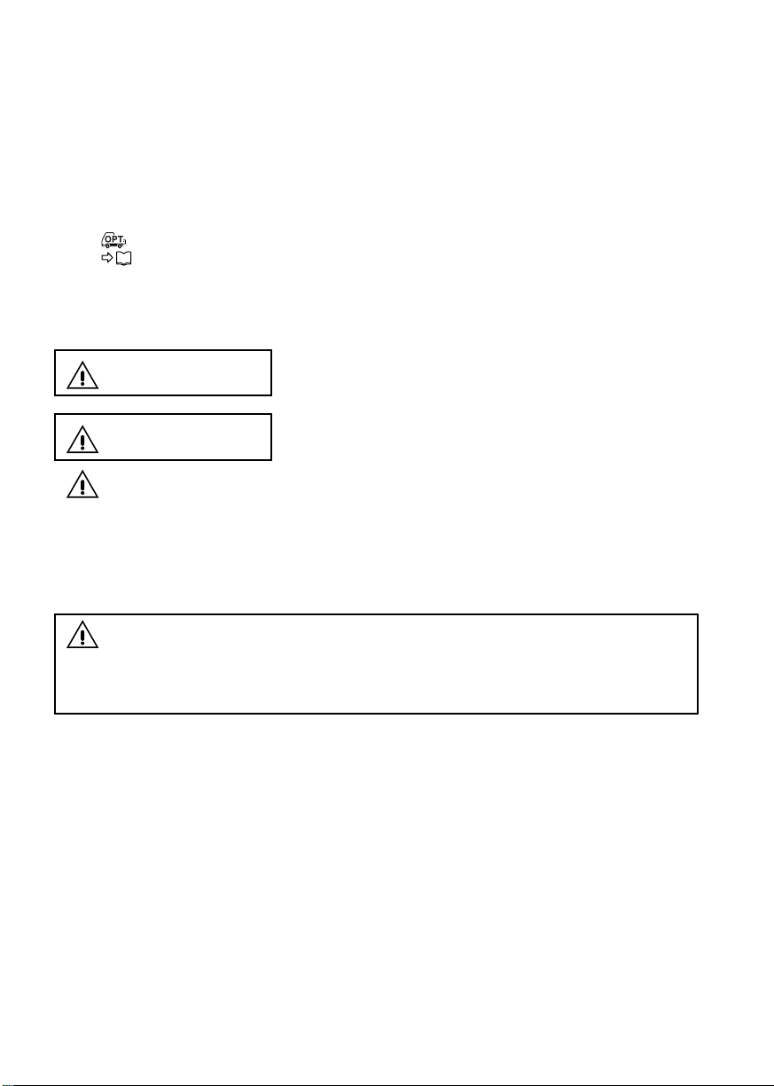
Chassis and engine numbers
1 Chassis number
The chassis number is indicated on the left
frame, near the left front wheel.
Example: FE84DD -
Chassis number
2 Engine number
The engine number is indicated on the left side of
the crankcase.
Example: 4M50 -
Vehicle model
Z11767
Z11768
Engine number
Engine model
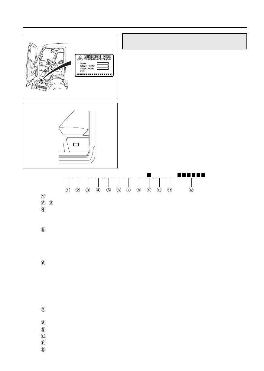
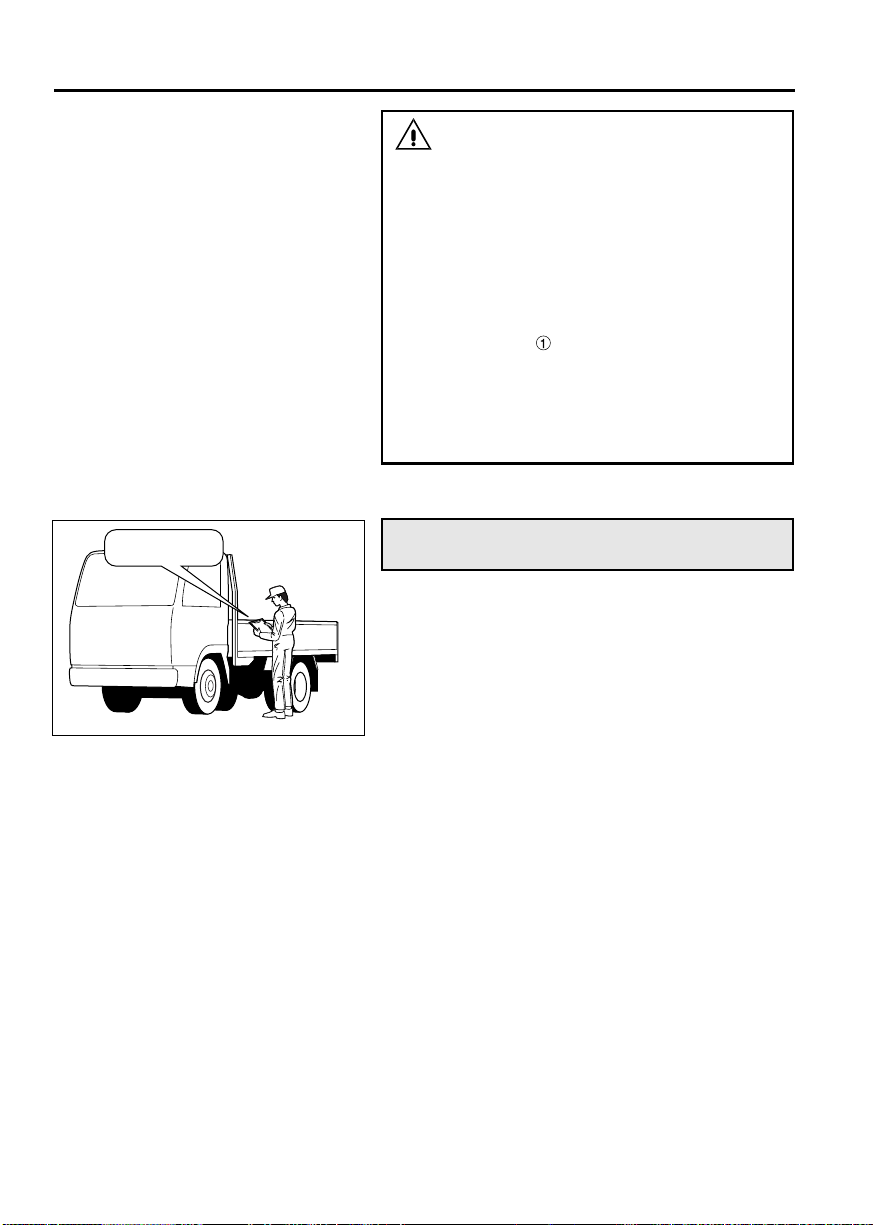
Powerline label
The powerline label located in the position shown
indicates the vehicle model, chassis number and
information relevant to the vehicle’s power transmission components.
Page 10
<Crew-cab model>
Country J: Japan
, Vehicle type L, 6: Incomplete vehicle
Gross vehicle weight / A: 10,001 to 14,000 lbs. / Hydraulic
Brake system B: 14,001 to 16,000 lbs. / Hydraulic
Line A: FE83D
Series (wheel base) D: 2.9 to 3.19 m (9.51 to 10.46 ft.)
Cab chassis type 1: Chassis cab for Mitsubishi Fuso
and make
Engine S: 4.899 L Diesel turbo charged and charge air cooled
Check digit
Model year A: 2010
Plant K: Kawasaki
Plant sequential number
1-3
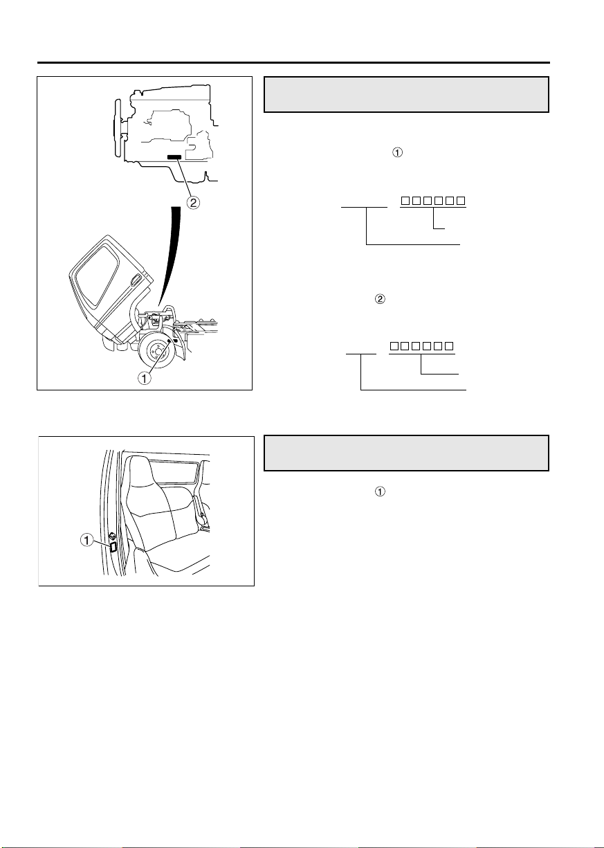
Vehicle identification number (VIN)
The VIN is stamped on a plate that is located as
shown in the illustration.
The VIN comprises 17 numbers and letters, the
meanings of which are listed below.
Z11959
Z11769
J AA6L D AS1 K
C: 16,001 to 19,500 lbs. / Hydraulic
B: FE84D
C: FE85D
D: FE84DW
E: FG84D
E: 3.2 to 3.49 m (10.49 to 11.44 ft.)
F: 3.5 to 3.79 m (11.48 to 12.43 ft.)
G: 3.8 to 4.09 m (12.46 to 13.41 ft.)
H: 4.1 to 4.39 m (13.45 to 14.40 ft.)
J: 4.4 to 4.69 m (14.43 to 15.38 ft.)
K: 4.7 to 4.99 m (15.41 to 16.37 ft.)
Page 11
1-4 Recommendation to drivers
Z11771
Maintenance
Checking your vehicle at regular intervals is very
important for maximizing performance and extending service life. It is recommended that you make a
habit of performing the following inspections.
This manual describes simple maintenance checks
and procedures that can be carried out by the
owner. If you have difficulty or your vehicle needs
maintenance work that is not shown in this manual,
please refer to an authorized dealer.
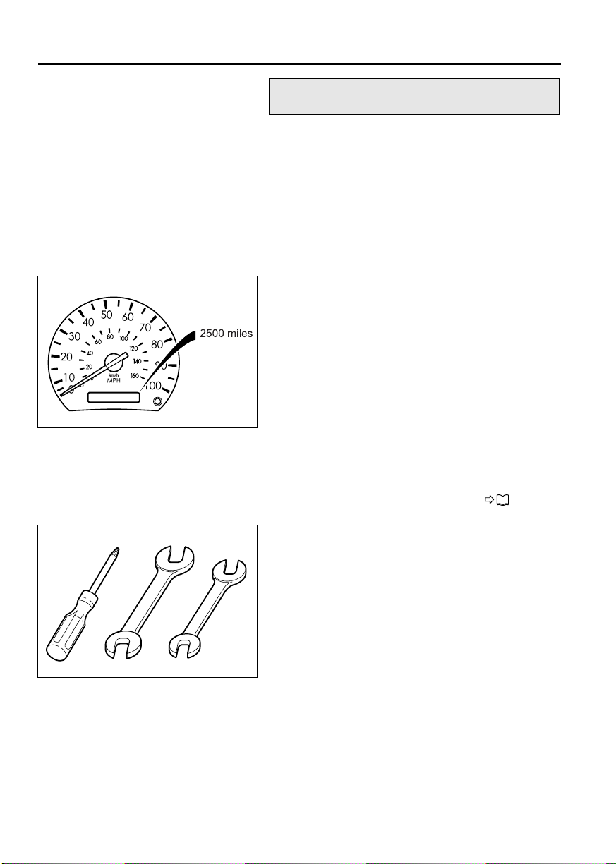
1 New vehicle inspection
After you have driven the first 4,000 km (2,500
miles), your vehicle requires a special inspection
and adjustments to compensate for the initial settlement of various parts. When the distance has been
reached, have your vehicle inspected by an authorized dealer by showing them this Owner’s Manual.
2 Pre-operational check
Make a habit of checking your vehicle at the start of
every day’s operation. This will ensure safe and
comfortable operation. P. 12-10
Z01367
3 Periodic inspection
In addition to maximizing the vehicle’s working life,
regular inspections also help prevent accidents.
Periodic inspection is based on either the distance
traveled (odometer reading) or period of use
(months/years).
The intervals between and content of periodic
inspections are as shown in the Maintenance
Schedule section. Please adhere to the maintenance schedule carefully.
Page 12

1-5
Fuels
Use only diesel fuels conforming to the following
recommendations, without any additives, for diesel
engines installed in Mitsubishi Fuso trucks.
1 Diesel-fuel properties
The following recommendations concerning diesel
fuel used with Mitsubishi Fuso diesel engines are
given for optimum fuel economy and performance.
Use condition Recommendation
Normal operation at
temperatures above
–12°C (10°F).
Operation at temperatures below –12°C
(10°F), or long-hour noload operation.
NOTE:
* ASTM is an acronym for the American Society for
Testing and Materials which recommends fuel containing 0.0015% – basis 15 ppm sulfur or less sulfur
content.
Note that a sulfur content exceeding 0.0015% –
basis 15 ppm sulfur deteriorates the performance of
emission control device.
ASTM D-975
Grade Ultra Low Sulfur
Grade 2-D*
ASTM D-975
Grade Ultra Low Sulfur
Grade 1-D*
To meet fuel requirements, it is necessary to obtain
cooperation from a reputable fuel oil supplier. Both
fuel suppliers and users are responsible for keeping
fuel clean.
2 Diesel fuel to be used in your engine
Use only a ultra low sulfur diesel fuel (with a sulfur
content of 15 ppm or lower) for refueling your Mitsubishi Fuso diesel engine. Otherwise, the catalyst
inside the diesel particulate filter (DPF) will not work
effectively and the DPF’s performance of removing
small particles (particulate matter or PM) in exhaust
gases will be degraded. Furthermore, your truck will
not meet emission regulations if you replenish it
with a non-approved fuel.
Page 13
1-6 Recommendation to drivers
3 Danger of fire and explosion by using
mixed fuel
Fuel containing 5% gasoline has a flash point as
low as 0°C (32°F), which can lead to a fire or explosion while the engine is running.
DANGER
NEVER MIX DIESEL FUEL WITH GASOLINE,
GASOHOL OR ALCOHOL.
USE OF FUEL MIXED WITH ONE OR MORE
OF THESE COULD LEAD TO A FIRE OR
EXPLOSION INVOLVING SERIOUS INJURY,
DEATH OR PROPERTY DAMAGE. IF YOU
ACCIDENTALLY USE GASOLINE OR ALCOHOL WHEN REFUELING THE VEHICLE,
REMOVE ALL OF IT FROM THE FUEL SYSTEM.
4 Adverse effects of mixed fuel on engine
Using diesel fuel mixed with gasoline, alcohol, or
both, has the following adverse effects on the
engine:
• Fuel viscosity becomes lower, resulting in
excessive wear, damage, and failure of fuel system parts.
• Difficulty in starting the engine will result due to
a reduced cetane number.
CAUTION
• The lower the cetane number, the more likely
internal engine damage will occur.
• Do not add antifreeze agents or other sub-
stances to the fuel. They could damage the
engine’s fuel injection system.
• If the fuel tank cap and breather (air hole)
become so dirty that the breather gets
blocked, the fuel tank may deform and the
fuel injection system may fail. Be sure to
clean them regularly.
Page 14
1-7
5 Refueling
WARNING
• Stop the engine before fueling.
• Never smoke when fueling since diesel
fuel could ignite or explode.
Never operate lighters or other items that
emit sparks.
• If you inadvertently put gasoline in the fuel
tank, pump it all out. Running the engine
with gasoline in the tank could cause a fire
or explosion endangering your or other
people’s lives.
CAUTION
Be careful not to allow the engine to run out of
fuel. Engine stall resulting from an empty tank
could cause damage to the fuel injection system.
NOTE:
Air will be present in the fuel system after the
engine has run out of fuel. This air will prevent the
engine from restarting even after it is adequately
refueled. You must bleed the fuel system before the
engine can be started.
P. 1 3 - 2 8
<125-liter fuel tank>
<113-liter fuel tank>
• 125-liter fuel tank
The fuel tank is on the right-hand side of the vehicle. To open the cap, slowly turn it counterclockwise. To close the cap, turn it fully clockwise.
Fuel tank capacity
125 liters (33 gallons)
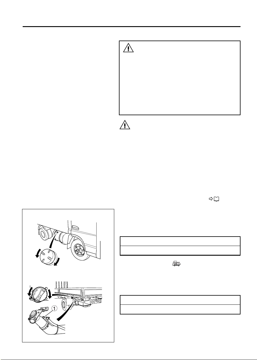
• 113-liter fuel tank
<FE: other than Crew-cab models>
The fuel tank is at the rear of the vehicle. To open
the fuel tank cap, slowly turn it counterclockwise. To
close the cap, turn it clockwise until you hear a click.
Fuel tank capacity
113 liters (29.8 gallons)
Z11891
Page 15
1-8 Recommendation to drivers
WARNING
• When filling the fuel tank using a gun-type
fuel pump, do not continue pumping after
the pump automatically stops. (The tank is
full at this point.) When filling the fuel tank
using any other method, stop as soon as
the surface of the fuel becomes visible
through the opening of the fuel filler. If you
supply so much fuel that it comes up to
the opening, fuel may leak though the
check valve when the vehicle starts
moving and when it stops moving. If fuel
leaks, carefully wipe it all up to prevent the
risk of fire.
• If the pointer of the fuel gauge is above the
“F” mark, do not add the fuel any more.
4000 km
(2500 miles)
Z18524
Handling of the new vehicle
The way the vehicle is handled when new greatly
affects its subsequent performance and service life.
Observe the following precautions when handling
the new vehicle.
1 Maintenance
The “new vehicle inspection” is very important for
extending the service life of your vehicle. We
strongly recommend that you have this inspection
carried out by an authorized dealer. Be sure to give
the dealer this manual at that time.
During the initial run-in period, oil is quickly contaminated. Replace the following oils and oil filter elements at the time of the “new vehicle inspection”.
At 4,000 km (2,500 miles)
• Engine oil
• Manual transmission gear oil
• Transfer gear oil <FG>
• Front axle housing gear oil <FG>
• Rear axle housing gear oil
Page 16
1-9
1000 km
(600 miles)
Z18525
2 Maximum engine speed during run-in
period
To avoid overburdening a new engine, limit engine
RPM to that indicated below for the first 1,000 km
(600 miles).
Then, run in your vehicle step by step at various
speeds, beginning with low gears.
Maximum engine RPM during run-in period
1,800 rpm
Reporting safety defects
If you believe that your vehicle has a defect that
could cause a crash or could cause injury or death,
you should immediately inform both the National
Highway Traffic Safety Administration (NHTSA) and
the Mitsubishi Fuso Truck of America, Inc. (MFTA).
If NHTSA receives similar complaints, it may open
an investigation, and if it finds that a safety defect
exists in a group of vehicles, it may order a recall
and remedy campaign. However, NHTSA cannot
become involved in individual problems between
you, your dealer, or MFTA.
To contact NHTSA, you may either call the Vehicle
Safety Hotline at 1-888-327-4236 (TTY: 1-800-424-
9153) or write to: Administrator, National Highway
Traffic Safety Administration, 400 Seventh Street,
S.W., Washington, DC 20590.
You can also obtain other information about motor
vehicle safety from the Vehicle Safety Hotline.
For further information, please visit the following
NHTSA website:
http://www.safercar.gov
Page 17

1-10 Recommendation to drivers
Obtaining service
At Mitsubishi Fuso Truck of America, Inc. (MFTA),
we are proud of the quality and workmanship that is
built into every MFTA Truck. We are equally proud
of our corporate commitment to promote the highest
possible degree of customer satisfaction with our
products and services.
Today’s trucks are extremely complex and are comprised of an enormous number of individual parts.
Occasionally, a failure of one of these parts may
occur. Should you experience such a failure, we are
confident that you will find an Authorized Dealer
prepared to provide you with high quality service.
Every Authorized Dealer has trained personnel,
plus the tools and equipment necessary to provide
for your various service needs. In the event that a
problem arises, we ask you to follow the procedure
outlined as follows, and in the sequence listed:
STEP 1: Contact your Nearest Authorized Dealer
This is the most direct and expedient way to obtain
service. Each Authorized Dealer has the ultimate
responsibility for providing the services and repairs
you may need. We recommend that you contact the
Service Manager of your nearest Authorized Dealer
for assistance. In the event that you feel additional
assistance is required, ask to speak to the General
Manager of the Authorized Dealer.
STEP 2: Contact MFTA
After the completion of Step 1, and in the event that
your nearest Authorized Dealer has been unable to
satisfactorily resolve the problem, please contact
MFTA’s Customer Service Representative at 1-877-
711-0707.
Please be prepared to provide the following information when you call:
• Your Name, Company Name, Address, Tele-
phone Number
• Vehicle Model
• Vehicle Model Year
• Vehicle Identification Number
• Mileage
• Name of Dealer contacted under Step 1, if appli-
cable
• Details of the Complaint/Comment
Page 18

1-11
You also may correspond with the Customer Service Representative in writing, addressed to:
MITSUBISHI FUSO TRUCK OF AMERICA, INC.
CUSTOMER SERVICE REPRESENTATIVE
2015 CENTER SQUARE RD.
LOGAN TOWNSHIP, NJ 08085
Page 19

Page 20

2-1
2. Warning labels
Locations in cab ................................................................................................................. 2-3
Locations outside cab ........................................................................................................ 2-6
Page 21

2-2 Warning labels
• The caution and warning labels show important
information. Be sure to read them before using
the vehicle.
• If any label has peeled so it is difficult to read, is
scratched or otherwise damaged, or has peeled
off completely, please inform an authorized
dealer. The warning and caution labels apply
only to the vehicle itself, not to any equipment
mounted on the vehicle. For information on caution and warning labels that apply to equipment
mounted on the vehicle, please refer to the
Owner’s Manual supplied by the manufacturer
of the equipment.
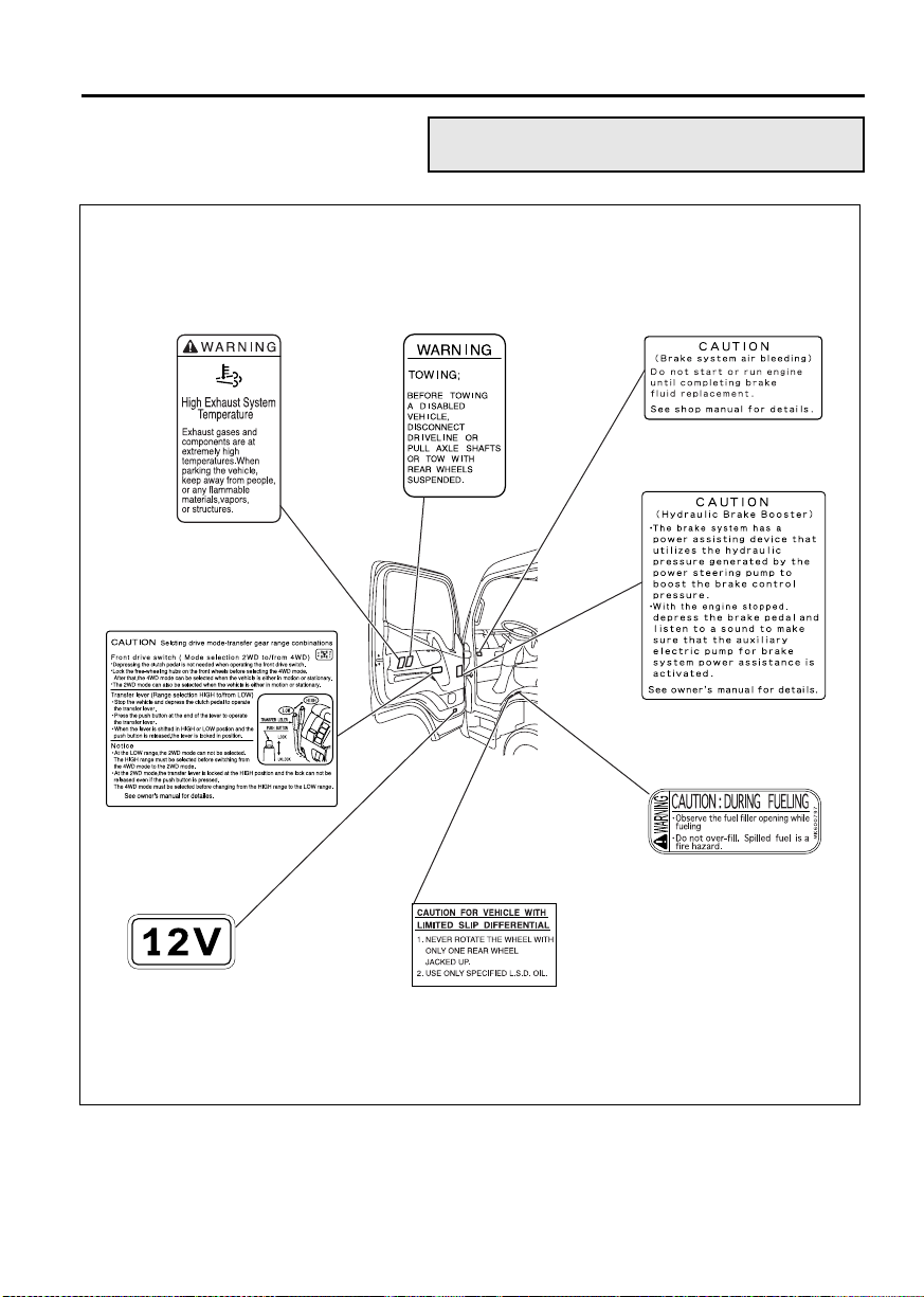
• The caution and warning labels are located in
the cab as shown below. Samples of these
labels are indicated in this and following pages.
Page 22
Locations in cab
2-3
High exhaust system
temperature
Transfer lever <FG>
Voltage
Towing <Automatic
transmission vehicles>
Limited slip differential
Hydraulic brake booster
<FE85>
Hydraulic brake booster
<FE85>
113-liter fuel tank
<FE: other than
Crew-cab models>
Z18526
Page 23
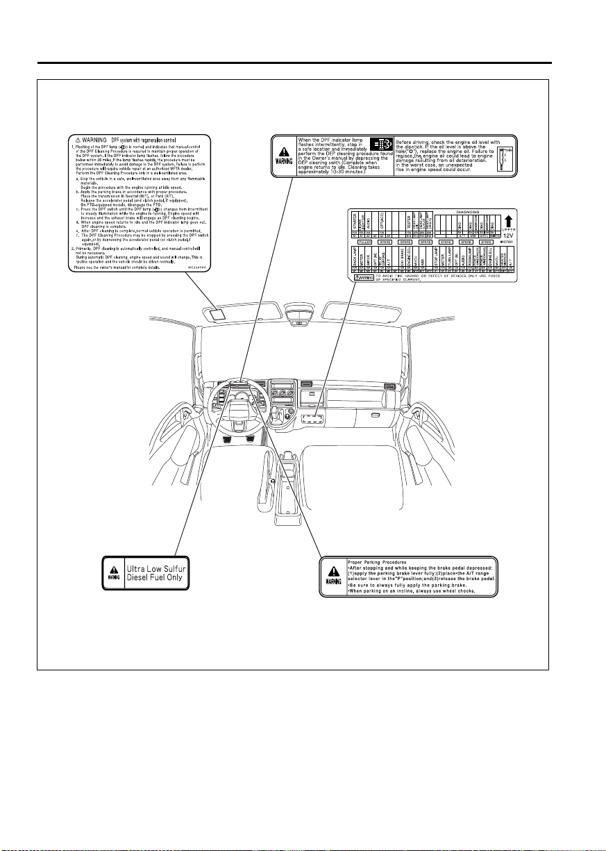
2-4 Warning labels
DPF system
DPF indicator lamp
Fuse
Fuel
Parking
<Automatic transmission vehicles>
Z19698
Page 24
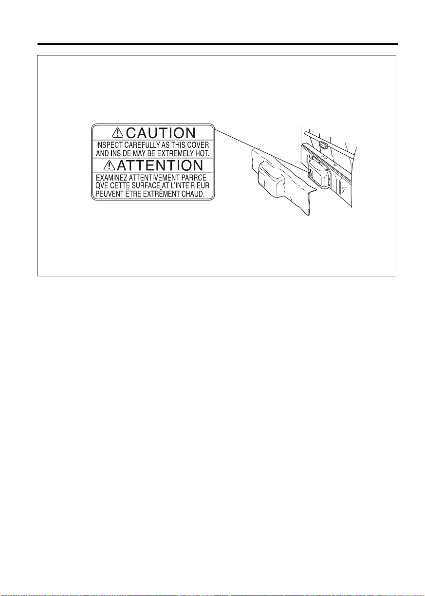
Engine inspection hatch
<Crew-cab models>
2-5
Z17778
Page 25
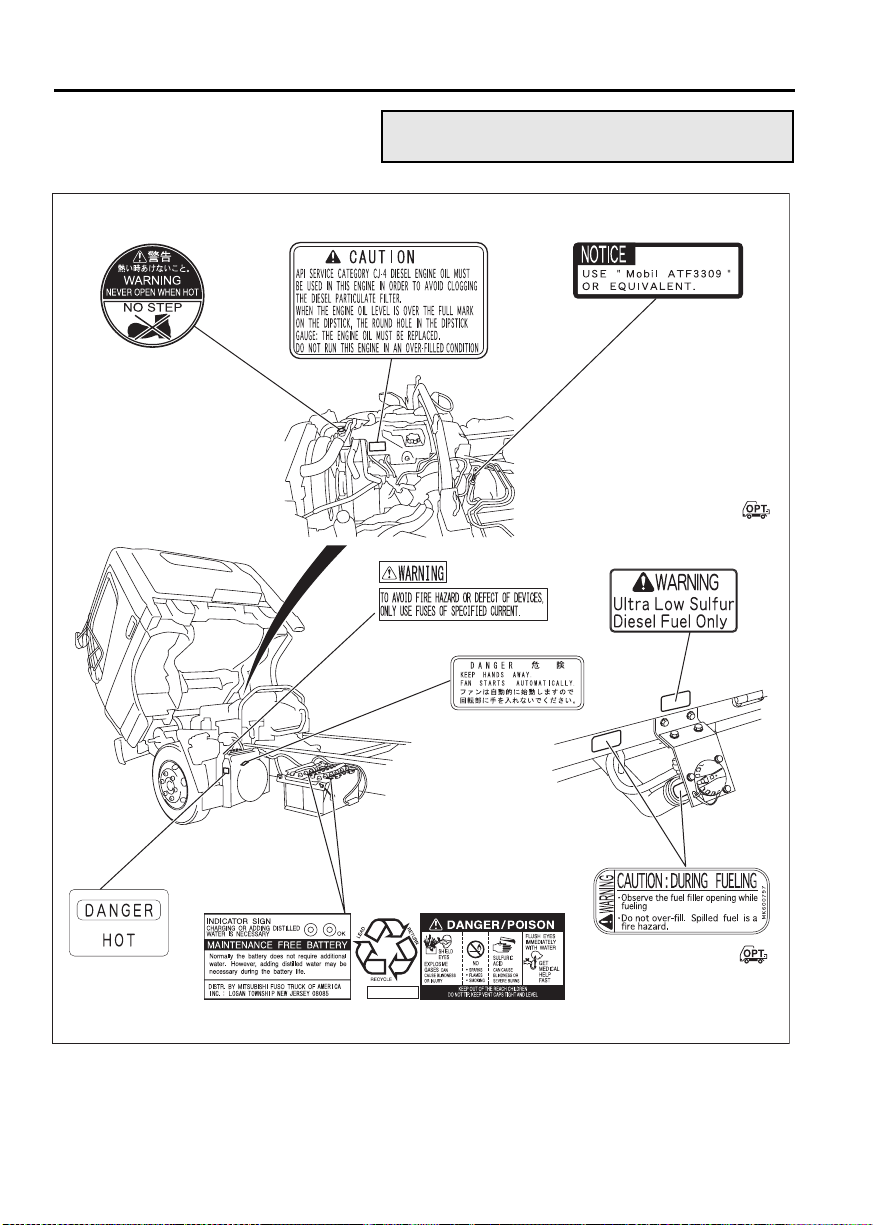
2-6 Warning labels
Locations outside cab
Pressure cap
Engine oil Automatic transmission fluid
113-liter fuel tank
High-current fuse
Oil cooler <Automatic
transmission vehicles>
<FE: other than
Crew-cab models>
Oil cooler
<Automatic
transmission
vehicles>
<The oil cooler
of Crew-cab
model is installed
in the other side>
Battery
113-liter fuel tank
<FE: other than
Crew-cab models>
Z16848
Page 26
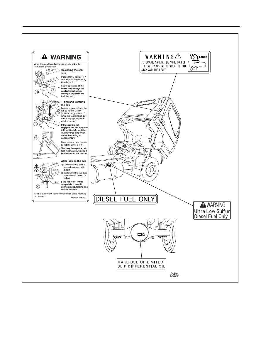
2-7
Cab tilt function
<Vehicles other than Crew-cab models>
125-liter fuel tank
Cab tilt function
<Vehicles other than Crew-cab models>
Limited slip differential
125-liter fuel tank
Z17822
Page 27

Page 28

3-1
3. Opening and closing
Starter key .......................................................................................................................... 3-2
Doors ................................................................................................................................. 3-2
Central door locks .............................................................................................................. 3-4
Keyless entry system ........................................................................................................ 3-5
Entering and leaving the vehicle ...................................................................................... 3-10
Door window glass ........................................................................................................... 3-12
Page 29
3-2 Opening and closing
Z08736
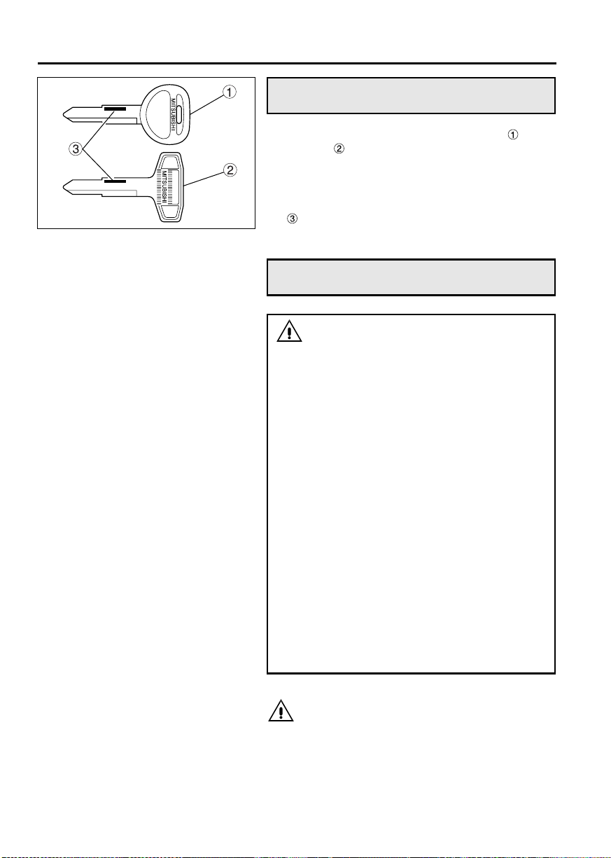
Starter key
• There are two starter keys: a main key and a
sub key .
You can use either of these starter keys for locking/unlocking the doors and starting/stopping
the engine.
• Please make a note of the starter key number
. You can purchase additional starter keys
from an authorized dealer.
Doors
WARNING
• To help prevent accidents, always check
for vehicles and pedestrians approaching
from behind before opening the doors.
• Driving with a door ajar can be very dan-
gerous. Make sure the doors are completely closed before starting.
• Exercise caution when opening a door in
strong wind. Otherwise, the wind could
catch the door and suddenly blow it open.
• Exercise caution when opening a door on
a downward slope. Otherwise, the inclination of the vehicle could cause the door to
suddenly fall open.
• When leaving the vehicle, take with you
any children or pets who was riding in the
cab. Never leave children or pets in the
cab. A child left in the cab could interfere
with the vehicle, causing it to move or
catch fire. Also, the cab gets extremely hot
in sunshine and in hot weather so a child
left in the cab could suffer heatstroke.
• When closing a door, be careful not to trap
your hand or anything else.
CAUTION
• Only open or close a door slowly without
applying undue force; otherwise the door
components could be damaged.
• Do not swing on or hang anything heavy on
any of the doors. Doing so could damage the
door components.
Page 30
Z10730
3-3
1 From the outside
•
To open, pull the outer handle toward you.
• Use the starter key to lock or unlock the door.
• It is possible to lock each door without using the
starter key. With the driver’s door or assistant
driver’s door, push the lock knob toward the
front of the vehicle then pull the outer handle
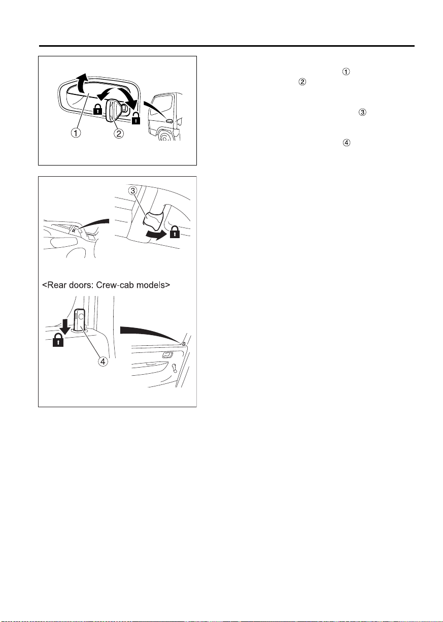
and keep it pulled as you close the door. With a
rear door, push the lock knob down then pull
the outer handle and keep it pulled as you close
the door.
NOTE:
• If your vehicle is not a Crew-cab model vehicle,
locking the driver’s door using the starter key or
lock knob also causes the assistant driver’s door
to automatically lock.
On the other hand, unlocking the driver’s door
using the starter key or lock knob unlocks only
the driver’s door.
• When you leave your vehicle, be sure to remove
the starter key from the starter switch to prevent
theft.
• Be careful not to lock the doors with the starter
key inside the vehicle.
Z10731
Page 31

3-4 Opening and closing
Z10732
2 From the inside
•
To close, use the door waist bar . Close the
door completely.
• To lock the driver’s door or assistant driver’s
door, push the lock knob toward the front of
the vehicle. To lock a rear door, push the lock
knob down.
• To unlock and open the driver’s door or assist-
ant driver’s door, push the lock knob toward the
rear of the vehicle then pull the inner handle .
To unlock and open a rear door, pull up the lock
knob then pull the inner handle .
CAUTION
Closing the door by pulling any part other than
the door waist bar could damage the door
mechanism.
Central door locks
Z14894
<Vehicles other than Crew-cab models>
• When the “LOCK” side of the switch is
pressed, both doors are locked. When the
“UNLK” side of the switch is pressed, both doors
are unlocked.
• When the lock knob on the driver’s door is
pushed forward, the passenger’s door is also
automatically locked. If the lock knob on either
door is subsequently pushed rearward, only that
door is unlocked.
• When the driver’s door is locked from the out-
side using the starter key, the passenger’s door
is automatically also locked. If the starter key is
subsequently used to unlock either door, the
other door remains locked.
Page 32

3-5
Keyless entry system
<Vehicles other than Crew-cab models>
1 The Grant of Equipment Authorization certificate for wireless transmitter
(remote control switch) RKE Transmitter MDL E11TG
1. FCC ID: MOZE11TG
2. This device complies with Part 15 of the FCC Rules. Operation is subject to the following
two conditions:
• This device may not cause harmful interference.
• This device must accept any interference received, including interference that may
cause undesired operation.
3. Changes or modifications not expressly approved by the party responsible for compliance
could void the user’s authority to operate the equipment.
Page 33

3-6 Opening and closing
2 The Grant of Equipment Authorization certificate for wireless receiver
Tuner MDL E11UG
1. FCC ID: MOZE11TG
2. This device complies with Part 15 of the FCC Rules. Operation is subject to the following
two conditions:
• This device may not cause harmful interference.
• This device must accept any interference received, including interference that may
cause undesired operation:
3. Changes or modifications not expressly approved by the party responsible for compliance
could void the user’s authority to operate the equipment.
Page 34

Z13209
3-7
3 Keyless entry system
The keyless entry system allows you to lock/unlock
the doors of the driver’s seat and assistant driver’s
seat by operating the remote-control switch .
WARNING
If you carry the keyless entry remote control
switch with you when traveling on an airplane, avoid pressing any button on the
switch. If you keep the switch in a suit pocket
or somewhere like a bag, prevent the switch
buttons from being accidentally pressed,
since the radio-wave signals emitted from the
switch could interfere with normal operation
of the airplane.
CAUTION
• Do not expose the remote control switch to
water, disassemble it, or apply shock by
dropping it.
• Do not leave the remote control switch in a
place that is exposed to direct sunlight or
where the temperature rises to 60
above. Doing so will shorten the life or cause
failure of the remote control switch.
• Do not remove the cover from the remote
control switch unless you replace the battery. Removing it for no reason could lead to
a remote control switch malfunction.
°C/140°F or
4 How to operate the remote control
switch
Point the remote control switch toward the cen-
•
ter of the cabin.
• Operate the remote control switch within 3 m
(9.8 ft.) from the center of the cabin.
• Press the “LOCK” button to lock all doors.
• Press the “UNLOCK” button once to unlock
the driver’s door. You can unlock the assistant
driver’s door if you press the “UNLOCK” button
one more time within 3 seconds.
NOTE:
The assistant driver’s door does not unlock if you
press the “UNLOCK” button more than 3 seconds
after unlocking the driver’s door.
Page 35

3-8 Opening and closing
Z11387
• When you press the buttons, be sure to press
them for at least one second. If a button does
not work after one press, press the button again
after one or two seconds.
• After locking the doors with the remote control
switch, always check that the doors are locked
by lifting the outside handle of a door.
• You can check the locking/unlocking of the
doors by the flashing of the hazard lamps and
the room lamp. Leave the switch of the room
lamp “•” (in the center “•” position).
When the doors are locked, the room lamp and
the hazard lamps flash twice.
When the doors are unlocked, the hazard lamps
flash once and the room lamp lights up for about
10 seconds.
• If you do not open a door within 30 seconds
after unlocking with the remote control switch,
the doors will automatically be locked again.
NOTE:
• The range in which you can operate the remote
control varies somewhat depending on the surroundings, such as proximity to a TV tower,
power station, broadcasting station, etc.
• If you lose the remote control switch or the
switch does not work, please contact an authorized dealer to obtain a spare remote control
switch.
The remote control switch does not work under the
following conditions:
• A door is open or incompletely closed.
• When the starter key is in the “ON” position.
• While the engine is running.
5 Replacing the remote control switch battery
The battery may have run down if the remote control switch does not lock or unlock the doors upon
pressing the corresponding button. Replacing the
battery will solve the problem.
WARNING
• Keep the batteries out of the reach of chil-
dren. If a child swallows a battery, visit a
doctor immediately.
• Do not disassemble, heat or drop the bat-
tery in water. Doing so could cause a fire
or explosion.
Page 36

3-9
CAUTION
• Use the designated standard type of battery.
If the battery is replaced with an incorrect
type, the battery could explode.
• Attach the battery with the “+” mark facing
upward.
• Do not use a metal tool such as tweezers to
replace the battery. Doing so could cause a
short circuit.
• Dispose of used batteries in accordance with
local regulations. Inconsiderate disposal
could adversely affect the environment. For
disposal, wrap the battery with tape, vinyl
sheet, etc. for insulation so that the battery
cannot contact other metal objects or be
exposed to water.
• Do not expose the inside of the remote con-
trol switch to water, and keep it away from
dirt and dust. Otherwise, the switch could
fail.
Designated battery Quantity
Lithium battery CR1616 1
Z12616
Z12617
1. Use a crosshead screwdriver to turn the
screw and remove the cover .
2. Place a new battery with the “+” mark facing
upward.
3. Reattach the cover and the screw.
4. Operate the switch and check that the remote
control works.
Page 37

3-10 Opening and closing
Entering and leaving the vehicle
WARNING
• Always use the step to climb into or down
from the vehicle. Never put your foot on
the wheel or tire since it could easily slip
off.
• The step can become slippery in rain or
snow. Firmly hold the grip while climbing
into or down from the vehicle. Holding the
grip is particularly important when snow
has settled and frozen on the step.
• If the soles of your shoes are oily or
greasy, you could slip when climbing
down from the vehicle or when operating
the brake or clutch pedal.
Wipe any oil and grease off the soles of
your shoes before entering or leaving the
vehicle.
• Do not hold luggage or other items in your
hands when entering or leaving the vehicle since this can be dangerous.
• Do not jump down from the vehicle. Jump-
ing down from the vehicle could cause you
to fall or sustain an injury.
• Take care when entering or leaving the
vehicle on a slope or in a strong wind
since the door could open or close suddenly.
Page 38

3-11
<FE>
<Rear doors: Crew-cab models>
CAUTION
• Climb into and out of the cab by holding only
• When entering or leaving an FG model truck,
<FG>
Z17779
the grip. For FG models, do not climb into
and out of the cab by holding HIGH-LOW
selector lever . If you hold onto any other
parts of the vehicle, they could break or fail.
do not place your feet or hands on the fender
. The fender could suffer damage. Also, the
fender can be dangerously slippery.
When climbing into and out of the cab, support your
body by at least three points at a time by firmly gripping the handle and fully placing your feet on the
steps . If you place your hand on the fender, put it
on the non-slip section .
Page 39

3-12 Opening and closing
Door window glass
WARNING
Do not allow a child to put its hands or head
out of a window. The child’s head or hands
could hit an object outside the vehicle, and
the child could be seriously injured in the
event of hard braking.
1 Power window switches
<Vehicles other than Crew-cab models>
WARNING
• Always make sure that no one has their
head or hands out of the window when
closing it. A body part could be injured if
caught in a closing window.
Never allow a child to open or close the
window.
• When a child is in the cab, be sure to press
the power window lock switch to prevent
the child from opening and closing the
assistant driver’s window. Otherwise, the
child may accidentally operate the power
window switch and get its hands or head
trapped.
Z10734
The power window switches function only when the
starter switch is in the “ON” position.
On the driver’s door, there are two switches: switch
for controlling the driver’s window and switch
for controlling the assistant driver’s window.
Switch for assistant driver’s window.
Press the switch to open the window.
Raise the switch to close the window.
CAUTION
Do not keep any door or window open in rainy
weather, and be careful not to spill a drink on
any of the window switches. If water or any
other liquid gets on a window switch, it can
cause a malfunction.
Page 40

3-13
2 Power window lock switch
<Vehicles other than Crew-cab models>
WARNING
When a child is in the cab, be sure to press
the power window lock switch to prevent the
child from opening and closing the assistant
driver’s window. Otherwise, the child may
accidentally operate the power window
switch and get its hands or head trapped.
Press the power window lock switch to prevent
the assistant driver’s window from being opened or
closed.
Pressing the switch a second time releases the
lock.
CAUTION
Do not keep any door or window open in rainy
weather, and be careful not to spill a drink on
any of the window switches. If water or any
other liquid gets on a window switch, it can
cause a fault.
Z10735
NOTE:
If a child is in your vehicle, it is important for safety’s
sake to press the power window lock switch to prevent the child from opening or closing the assistant
driver’s window.
Page 41

3-14 Opening and closing
<Front doors>
<Rear doors: Crew-cab models>
Z12531
3 Window regulator handle
<Crew-cab models>
Turn the window regulator handle to open or
close the window.
Open
Close
CAUTION
The front door window glass lowering limit is
near the door waist bar . Trying to lower it further could damage the internal mechanism.
Page 42

4-1
4. Seat and steering wheel adjustments
Seats .................................................................................................................................. 4-2
Seat belts ........................................................................................................................... 4-5
Steering wheel ................................................................................................................... 4-8
Page 43

4-2 Seat and steering wheel adjustments
Seats
WARNING
• Adjusting the seat while the vehicle is in
motion is dangerous as the seat may move
more than you intend. Be sure to stop the
vehicle and set the parking brake before
performing any adjustment of the seat.
• After you have adjusted the seat, gently
move or rock the seat to ensure that it is
locked in the desired position.
• When adjusting the seat, keep your hands
away from the bottom of the seat and from
moving parts of the seat. Otherwise, you
could suffer an injury by getting your
hands and fingers trapped.
• When adjusting the angle of the seatback,
keep your back or hand pressed against it.
Otherwise, the seatback could suddenly
return to its original position and injure
you by hitting your face or other body
parts.
Z11863
1 Driver’s seat
1.1 Correct driving position
• Before driving the vehicle, adjust the seat with
reference to the following points:
Your back must touch the seatback, and you
must be able to see the warning lamps and
gauges.
You must be able to reach and firmly press
the pedals.
You must be able to operate the steering
wheel and switches with ease.
You must be able to operate the shift lever
with ease.
You must be able to fasten the seat belt correctly.
• Adjust the steering wheel to a position at which
you can operate it comfortably with your arms
slightly bent.
Page 44

Z10741
4-3
1.2 Making adjustments
• Slide seat forward or backward while holding
slide adjustment lever raised. After making
the adjustment, release the lever and move the
seat back and forth slightly to lock it in position.
• To adjust the angle of the seatback , raise
reclining lever .
• Lower the armrest to use it. Turn the armrest
knob to adjust the height of the armrest in its
lowered position.
Up
Down
2 Assistant driver’s seat
Assistant driver’s seat
Center seat
It is possible to tip the seatback fully forward. With
the lever pulled, grasp the seatback at the top
and tip it forward.
After returning the seatback to its original position,
gently rock it to make sure it is locked in place.
Z18529
Page 45

4-4 Seat and steering wheel adjustments
Z12099
3 Rear seat – Crew-cab models
Storage compartments are located under the rear
seat. The rear seat can be folded up for access to
them. When you wish to stow or remove something
from these compartments, release the hooks at
the base of the seat and raise the seat cushion .
To retain the seat cushion, use the retaining bands
that are attached to the seatback. Fit the loop
at the end of each retaining band over the corresponding hook on the seat cushion.
Page 46

Z11862
4-5
Seat belts
• To help prevent injury in the event of a sudden
stop or accident, the driver and all passengers
must wear their seat belts correctly.
• When wearing your seat belt, sit back in your
seat with your back straight. If a seat belt is used
incorrectly, its effectiveness is greatly diminished and it could aggravate injuries in the event
of accident.
• For details of seat belt usage for children and
pregnant women, refer to “Children and babies”
and to “Pregnant women”. P. 4-7
WARNING
• Passengers must never be in the cargo
area while the vehicle is in motion. Unless
seated and properly belted up, the risk of
injury is greatly increased.
• Seat belts should be worn as low as possi-
ble over the hips. Wearing a seat belt
across the abdomen could be dangerous
since undue pressure would be placed on
internal organs in the event of a collision.
• Make sure that the seat belt is not twisted
when fastening it. A twisted seat belt could
be dangerous since its reduced width will
apply a larger force to a smaller part of
your body in the event of impact.
• Replace any seat belt that is cut or frayed,
or if its buckle does not work properly.
• Never use a single seat belt for more than
one person.
• It is dangerous to fasten or unfasten your
seat belt while driving since the momentary diversion of your attention could lead
to a serious accident. Always stop the
vehicle first.
• The left and right seats feature 3-point lap and
shoulder belts with Emergency Locking Retractor (ELR), while the middle seat features a 2point lap belt.
Page 47

4-6 Seat and steering wheel adjustments
Z10760
1 Lap and shoulder belts with ELR
NOTE:
It is not necessary to adjust the length of these seat
belts.
An ELR seat belt extends and retracts automatically
as its wearer moves but locks automatically for protection in the event of a sudden stop or shock.
The belt’s tightness should be adjusted automatically. If there is any looseness, lift the shoulder belt
gently and the mechanism will take up the slack.
With the belt properly tightened, the risk of it slipping off in a collision is reduced.
• Fastening
1. Hold tang and gently extend the belt. If the
belt locks or is difficult to extend, let it retract and
pull it gently again.
2. Take care that the belt does not become twisted.
Insert the tang into the buckle until you hear a
click.
3. Pull on the tang to confirm that it is locked in.
4. Adjust the belt so it is across your hips and
shoulder.
Z11726
Z01351
• Unfastening
1. Press the red button to unlock the buckle.
2. The belt automatically retracts when unlocked.
To prevent the tang causing damage or injury,
hold it while the belt retracts.
3. Adjust the tang stopper to locate the tang in
an easy-to-reach position and prevent it from
slipping.
Page 48

Z08774
4-7
2Lap belt
•
Fastening
1. Take care that the belt does not become twisted.
Insert the tang into the buckle until you
hear a click.
2. Pull on the tang to confirm that it is locked in.
3. Adjust the belt so it is low across your hips.
4. To adjust the belt’s length, hold the tang at 90°
to the belt.
Pull the belt end to shorten the belt or the tang
to lengthen it.
To lengthen
To shorten
WARNING
For maximum protection in the event of an
accident, the belt must not be loose. A loose
belt could even aggravate injuries.
• Unfastening
1. Press the red button to unlock the buckle.
2. When the belt is not in use, insert its tang into
the buckle.
3 Children and babies
When carrying children or babies, they must be
•
restrained properly to minimize the risk of injury
in the event of a sudden stop or accident. Never
allow children to stand or kneel on the seats. For
maximum safety, we recommend fitting and
using a restraint system that complies with Federal Motor Vehicle Safety Standards.
The use of child and/or baby restraint systems is
mandatory in some states. Please abide by your
state’s regulations.
• Older children may sit on the regular seats and
use the regular seat belts. However, make sure
that the shoulder belts do not cross their necks
or faces.
4 Pregnant women
Since a seat belt could exert undue pressure on the
abdomen in the event of an accident, pregnant
women should consult a doctor about the use of
seat belts before riding in the vehicle.
A pregnant woman should wear her seat belt as low
as possible across the hips, not across her abdomen.
Page 49

4-8 Seat and steering wheel adjustments
5 Seat belt care
•
Periodically, check the action of the mechanical
parts such as the buckles, tangs, and emergency locking retractor (ELR) units. Check also
for any damage that could stop the seat belts
from functioning properly.
Replace seat belt unit if there is any malfunction
or damage.
• Replace any webbing that is cut, frayed, or oth-
erwise damaged.
• Replace any seat belt that has received a shock
due to a collision.
• Keep sharp or other potentially damaging
objects away from the seat belts, especially the
webbing.
• Keep the seat belts clean and dry. Use a mild
soap and lukewarm water to clean seat belts.
Such solvents as gasoline and thinner may seriously affect the strength of the webbing.
P. 1 2 - 9 5
• Never attempt to bleach or dye the seat belts, as
this could weaken them considerably.
• Do not attempt to remove the seat belts or dis-
assemble the ELR units.
Steering wheel
WARNING
• After every adjustment, try to move the
steering wheel back and forth to make
sure that it is securely locked. Unless the
lever returns to its original position, the
steering wheel may move while the vehicle
is in motion and cause an accident.
• Make adjustments with the vehicle station-
ary. Adjusting the steering wheel while
driving is dangerous since it could detract
from your concentration or cause the
steering wheel to move more than desired.
The steering wheel can be adjusted to the preferred
height and tilted forward/backward. Adjust the
steering wheel as well as the seat to the best positions for easy safe driving.
Page 50

Z14892
4-9
• Pull the lock lever then adjust the steering
wheel to the height and angle that are most
comfortable for you.
• Push the lock lever back in to securely retain the
steering wheel.
Adjust
Retain
Page 51

Page 52

5-1
5. Switches and controls
Arrangement of switches and controls ............................................................................... 5-2
Starter switch ..................................................................................................................... 5-3
Starting the engine ............................................................................................................. 5-5
Warming up the engine ...................................................................................................... 5-9
Stopping the engine ......................................................................................................... 5-11
Pedals .............................................................................................................................. 5-12
Gearshift lever .................................................................................................................. 5-13
Range selector lever ........................................................................................................ 5-14
Overdrive switch .............................................................................................................. 5-17
Parking brake lever .......................................................................................................... 5-17
Combination switch .......................................................................................................... 5-18
Cruise control ................................................................................................................... 5-22
Hazard warning lamp switch ............................................................................................ 5-27
Rheostat control switch .................................................................................................... 5-28
Van body dome light switch ............................................................................................. 5-28
Rearview mirrors .............................................................................................................. 5-28
Mirror heater switch ........................................................................................................ 5-29
DPF cleaning switch ........................................................................................................ 5-30
Page 53

5-2 Switches and controls
<Manual transmission vehicles>
Z18530
<Automatic transmission vehicles>
Arrangement of switches and
controls
Starter switch
Accelerator pedal
Brake pedal
Clutch pedal <manual transmission vehicles>
Gearshift lever <manual transmission vehicles>
Parking brake lever
Hazard warning lamp switch
Combination switch
(wiper and washer switch, exhaust brake switch)
Combination switch
(lighting switch, passing/dimmer switch, turn signal switch)
Front drive switch <FG> P. 8-3
DPF cleaning switch
Central door lock switch <vehicles other than
Crew-cab models> P. 3-4
Oil level check switch P. 12-24
Cruise control main switch
<vehicles with cruise control>
Range selector lever
<automatic transmission vehicles>
Overdrive switch
<automatic transmission vehicles>
Shift lock release knob
<automatic transmission vehicles>
Cruise control SET/RESUME switch
<vehicles with cruise control>
Rheostat control switch
Van body dome light switch
<vehicles other than Crew-cab models>
HIGH-LOW selector lever <FG> P. 8-4
Mirror heater switch <option>
Z18531
Page 54

5-3
Starter switch
WARNING
Never turn the starter switch to any position
other than the “ON” position while driving
the vehicle. Turning the starter switch to the
“ACC” position would be dangerous because
the engine would stop and the following
problems would occur:
• The braking force is severely reduced.
• The power steering system would stop
working so the steering action would
become extremely heavy.
• The fuel injection system can malfunction.
• The electric circuits for the warning lamps
and meters would stop working, and elec-
tric parts could fail.
When the starter key is removed from the
starter switch, the steering wheel locks, making steering impossible.
CAUTION
• Do not turn the starter switch to the “START”
position while the engine is running. Doing
so could damage the starter.
• The starter key cannot be turned from the
“ACC” position to the “LOCK” position
unless it is pressed in. Do not attempt to turn
it by force. Keep the key pressed in while
turning it from the “ACC” position to the
“LOCK” position.
• If you park the vehicle over an extended
period of time, always place the key in the
“LOCK” position and remove it from the
starter switch. Leaving the key in the “ON”
or “ACC” position could run down the battery.
• Avoid using the “ACC” position for long
periods, for example, for listening to the
radio, as the battery could be completely discharged.
Page 55

5-4 Switches and controls
Z10782
• LOCK
The starter key can be inserted and removed
in this position only. To place the key in the
“LOCK” position, turn it to the “ACC” position
then press it in. Keep it pressed in while turning
it to the “LOCK” position. When the key is
removed, the steering wheel locks.
The lighting switch, rheostat control switch, hazard warning lamps, interior lamp, horn, central
door locks and turn signal lamps can be used.
• ACC
The engine is shut off or is not running in this
position.
The cigarette lighter can be used. Audio equipment (radio, etc.) installed and connected in the
approved manner can also be used.
• ON
The engine is running in this position.
All electrical circuits are operable.
• START
The engine is turned over and started in this
position.
Once the engine is running, release the key and
the switch will automatically return to the “ON”
position.
NOTE:
• Turn the key only after inserting it fully in the
starter switch.
• If you are unable to turn the key, gently turn the
steering wheel clockwise and counterclockwise
as you turn the key.
• The starter key on an automatic transmission
vehicle can neither be turned to the “LOCK”
position nor pulled out unless the range selector
lever is in the “P” position.
Page 56

Z11944
5-5
Starting the engine
WARNING
• Do not start or warm up the engine in a
garage or other closed area. When starting
the engine or entering or leaving a garage,
do not run the engine for longer than is
necessary as the accumulation of exhaust
gas in closed areas is very dangerous.
Exhaust emissions contain carbon monox-
ide (CO), which if breathed can cause
unconsciousness or death.
• If you smell exhaust gases inside the cab,
inspect the exhaust pipe and check
whether exhaust gases are leaking
through holes or cracks caused by corro-
sion or damage. If exhaust gases are leak-
ing, have the exhaust pipe inspected by an
authorized dealer.
If exhaust gases that have leaked from the
exhaust pipe come into the cab, ventilate
the cab with fresh air by opening the win-
dows fully or by opening the doors.
• Make sure that there are no flammables
under or behind the parked vehicle, espe-
cially close to the exhaust pipe. A fire
could be started by the heat from the
engine or exhaust pipe.
• When you start the engine, be sure to sit in
the correct position on the driver’s seat to
wait for the engine to warm up. If you are
leaning out of the door window or other-
wise incorrectly seated and the vehicle
suddenly moves, a serious accident could
occur.
CAUTION
• It is dangerous to push-start the engine.
Only push-start the engine when it is
unavoidable. It is impossible to push-start an
automatic transmission vehicle, and
attempting to do so could damage the transmission.
• Do not use ether or other vapor compound
type starting aids. Use of such fluid on this
engine could result in serious damage.
Page 57

5-6 Switches and controls
Z11845
NOTE:
• When the engine has started, allow it to warm
up until the needle in the coolant temperature
gauge starts to move.
• Do not continue operating the starter for more
than 15 seconds as this could damage it or discharge the battery.
• If you operate the starter continuously for 10
seconds and the engine still does not start, turn
the starter switch to the “ACC” position and wait
about 30 seconds for the battery to recover
before performing the starting procedure again.
• On a vehicle that has not been operated for a
week or more, or after replacement of engine oil
or engine oil filter element, be sure to crank the
engine before starting it. P. 5 - 8
• In a cold region, using a high-capacity battery
improves engine startability.
1 Pre-starting steps
1. Pull parking brake lever to fully apply the parking
brake.
2. Manual transmission vehicles:
Place gearshift lever in the neutral position.
Automatic transmission vehicles:
Place the range selector lever in the “P” position.
NOTE:
For safety, the engine in a manual transmission
vehicle cannot be started unless the gearshift lever
is in the neutral position.
In an automatic transmission vehicle, the engine
cannot be started unless the range selector lever is
in “P” or “N” position. It is safer to start the engine
with the range selector lever in the “P” position.
Start the engine with the range selector lever in the
“N” position only when absolutely necessary, for
example, if the engine stops while the vehicle is on
a railroad crossing.
Z08913
2 Starting procedure
1. Turn the starter switch to the “ON” position.
Page 58

Z08914
Z08915
Z08915
5-7
2. Check whether the indicator lamp illuminates or not.
• When the indicator lamp does not illumi-
nate
Automatic transmission vehicles: While holding
down the brake pedal, turn the starter switch to
the “START” position to start the engine.
Manual transmission vehicles: While holding
down the clutch pedal , turn the starter switch
to the “START” position to start the engine.
• When the indicator lamp illuminates
Wait until the indicator lamp goes out;
Automatic transmission vehicles: While holding
down the brake pedal, turn the starter switch to
the “START” position to start the engine.
Manual transmission vehicles: While holding
down the clutch pedal , turn the starter switch
to the “START” position to start the engine.
NOTE:
<FE84, FE85, FG>
If the engine is difficult to start after the indicator
lamp has gone out, the fuse of the preheating circuit
may be blown out. Check the fuse if this happens.
P. 1 3 - 1 6
<FE83>
If the engine is difficult to start and the lamp is
illuminated, the preheating circuit is faulty.
Have the circuit repaired by the nearest authorized
dealer.
Page 59

5-8 Switches and controls
3. After the engine has started, let it warm up until
the water temperature gauge needle begins to
move. P. 5-9
Z08917
Engine idling speed
625 to 675 rpm
3 Starting the engine when vehicle has
been parked over an extended period
When the vehicle is not used for a week or more or
the engine oil and oil filter are replaced, the engine
becomes starved of oil. Before the engine is started,
therefore, it must be cranked in accordance with the
following procedure to distribute oil to its various
components.
CAUTION
• To ensure maximum safety, be sure to pull
the parking brake lever fully to apply the
parking brake and block the wheels with
chocks thus preventing the vehicle from
accidentally moving.
• Performing the cranking is of essential
importance in terms of protecting the turbocharger.
1. Pull the parking brake lever to fully apply the
parking brake.
2. Manual transmission vehicles:
Place gearshift lever in the neutral position.
Automatic transmission vehicles:
Place the range selector lever in the “P” position.
3. Without depressing the accelerator pedal, place
the starter switch in the “START” position and
crank the engine for roughly 15 seconds.
If the engine starts, release the starter key and
do not depress the accelerator pedal for roughly
15 seconds.
Page 60

Z11846
Z11944
5-9
4 Starting the engine with the cab tilted
When you need to start the engine with the cab
tilted for inspection or servicing purposes, be sure
to observe the following safety precautions:
• Set the parking brake firmly and chock the
wheels.
• With a manual transmission vehicle, make sure
that the gearshift lever is in the neutral position.
With an automatic transmission vehicle, make
sure that the range selector lever is in the “P”
position.
• Make sure nobody is near the engine compart-
ment, then place the starter switch in the
“START” position to start the engine.
Warming up the engine
After the engine has started, let it warm up until the
water temperature gauge needle begins to move.
WARNING
• Do not warm up the engine in a garage or
other closed area. When starting the
engine or entering or leaving a garage, do
not run the engine for longer than is necessary as the accumulation of exhaust gas
in closed areas is very dangerous.
Exhaust emissions contain carbon monoxide (CO), which if breathed can cause
unconsciousness or death.
• If you smell exhaust gases inside the cab,
inspect the exhaust pipe and check
whether exhaust gases are leaking
through holes or cracks caused by corrosion or damage. If exhaust gases are leaking, have the exhaust pipe inspected by an
authorized dealer.
If exhaust gases that have leaked from the
exhaust pipe come into the cab, ventilate
the cab with fresh air by opening the windows fully or by opening the doors.
• Make sure that there are no flammables
under or behind the parked vehicle, especially close to the exhaust pipe. A fire
could be started by the heat from the
engine or exhaust pipe.
Page 61

5-10 Switches and controls
CAUTION
Racing the engine immediately after it has
started causes excessive wear of cylinders and
pistons, leading to engine malfunction. Be sure
to warm up the engine to operating temperature
before full load operation according to the procedures described here.
NOTE:
Idling the engine for long time wastes fuel, and is
therefore detrimental to environmental protection
and resource conservation. So shut down the
engine whenever you leave the vehicle, even for a
short period.
If you start to drive immediately after starting the
engine (while the engine is still cold), you will
encounter the following problems:
• In a cold region, the extreme coldness of the
engine will cause poor ignition of fuel, making
the engine prone to knocking.
You may encounter any or all of the following conditions. They are due to the actions particular to the
oxidation catalyst inside the diesel particulate filter
(DPF) and do not indicate any abnormalities.
• White smoke from the exhaust pipe when set-
ting the vehicle in motion after idling the engine
for a relatively long-time or when accelerating
the vehicle.
• White smoke from the exhaust pipe when the
vehicle starts off immediately after the engine is
started.
• The exhaust smells irritating (with a vinegar-like
odor).
Page 62

5-11
Stopping the engine
WARNING
• Never allow the vehicle to coast with the
engine stopped as braking may be dangerously sluggish and extremely difficult
steering may result. This may also cause
trouble in the fuel injection system.
• The engine and exhaust pipe are
extremely hot just after stopping the vehicle. Avoid parking the vehicle where the
exhaust pipe could set fire to materials
such as dry grass.
• Do not stop the engine for parking with the
steering wheel fully turned to either direction. This will cause the power steering
system pressure to drop, thus causing the
steering wheel to return rapidly, possibly
injuring you.
CAUTION
• If you stop the engine immediately after
uphill or high-speed driving, the oil supplied
to the rotor shaft of the turbocharger will rise
to an abnormally high temperature and the
rotor shafts could seize up. To avoid this, run
the engine at idle for at least 3 minutes
instead of stopping it immediately.
• The engine should only be stopped from an
idle. Stopping it at a high RPM could result in
an engine malfunction.
Z11845
1. Hold down the brake pedal and apply the parking brake.
2. Manual transmission vehicles:
Place gearshift lever in the neutral position.
Automatic transmission vehicles:
Place the range selector lever in the “P” position.
Page 63

5-12 Switches and controls
More than
3 minutes
3. Allow the engine to idle for more than 3 minutes
before stopping it.
When the vehicle is in motion, engine parts
become extremely hot. This is particularly true
during uphill or high-speed driving. Therefore,
let the engine cool down sufficiently by allowing
it to idle for a time before stopping it.
Z16069
4. Turn the starter switch to the “ACC” position to
stop the engine.
Z08812
Pedals
Accelerator pedal
Z08813
WARNING
If you use a floor mat, lay it correctly and
make sure it is suitable for the size of the
vehicle. It is dangerous for a floor mat to
cover the accelerator pedal or for floor mats
to be laid in multiple layers since the accelerator pedal may be prevented from returning
when released.
Racing the engine also increases fuel consumption.
Page 64

5-13
Brake pedal
WARNING
Allowing empty beverage cans or other
objects to get under the brake pedal is
extremely dangerous as they will interfere
with brake pedal movement. Keep the floor
free of any objects obstructive to operation
of the pedal.
• In a vehicle that has disc brakes, illumination of
the warning lamp while the vehicle is being
driven shows that the disc brake pads are due
for replacement. Have the disc brake pads
inspected by an authorized dealer.
The warning lamp always illuminates when
the starter switch is turned from the “ACC” position to the “ON” position. Provided it goes off
approximately three seconds later, the disc
brake pads are normal.
• Use the brake pedal correctly. P. 7-8
Clutch pedal
<Manual transmission vehicles>
• Do not operate the vehicle with your foot on the
clutch pedal as doing so can shorten the service
life of the clutch. Driving with your foot on the
clutch pedal could prevent engine braking and
exhaust braking from taking place.
• Depress the clutch pedal fully when changing
gear. If you do not depress the clutch pedal far
enough, the clutch will slip, possibly damaging
the clutch discs.
Gearshift lever
<Manual transmission vehicles>
WARNING
When the gearshift lever is in the neutral
position, never keep your hand on it. Such
forward or backward pressure on the lever
could cause the vehicle to move accidentally,
possibly leading to an accident.
Page 65

5-14 Switches and controls
CAUTION
• Shifting from a forward gear to the reverse
gear or vice versa, should be done only after
the vehicle has come to a complete stop.
When backing up, always double check to
make sure that there is nothing in your path.
• When the gearshift lever is in the neutral
position, never keep your hand on it. Such
forward or backward pressure on the lever
could cause the transmission to malfunction, especially if you use a gearshift lever
extender because the gearshift lever is very
likely to move even if the pressure on the
extender is slight.
• Depress the clutch pedal fully whenever
changing gear. If you do not depress the
pedal completely, the clutch will slip and the
clutch disc will be damaged, which could
lead to an accident.
• The shift pattern is inscribed on the top of gear-
shift lever.
• When the gearshift lever is placed in the reverse
(R) position, the backup lamps light up and the
backup buzzer sounds simultaneously.
Button
Z18275
Range selector lever
<Automatic transmission vehicles>
The range selector lever is used to select gear
ranges. Select lever positions carefully to ensure
proper engagement of each gear.
1 Using the range selector lever
: While depressing the brake pedal, push the
button and move the range selector lever.
The lever cannot be moved unless the
starter switch is in the “ON” position.
: Push the button and move the lever.
: Move the lever without pushing the button.
Z11851
Page 66

Shift lock
release knob
Z11852
5-15
NOTE:
• Never push the button for the range selector
lever movements indicated by the black arrows
( ) in the illustration. With the button pressed,
the lever could unexpectedly slip into the “P”,
“R”, “3” or “2” position.
• For safety, the range selector lever cannot be
moved out of the “P” position unless the brake
pedal is depressed. Even with the brake pedal
depressed, the range selector lever cannot be
moved if the starter switch is in the “LOCK” position or “ACC” position.
If the range selector lever cannot be moved out of
the “P” position even with the starter switch in the
“ON” position and the brake pedal depressed, move
the range selector lever while pushing the shift lock
release knob.
This problem can be caused by an electrical fault,
so have an inspection carried out by an authorized
dealer.
2 Ranges
P: Used when stationary, for example, when start-
ing or warming up the engine. The starter key
can be removed with the range selector lever in
this position.
R: For backing up. The backup lamps illuminate,
and a warning buzzer sounds.
N: The engine can be started with the lever in this
position, but it is safer to use the “P” position.
D: For normal driving. With the overdrive switch in
the “ON” position, gearshifts are made automatically using the 1st through 6th gears. With the
overdrive switch in the “OFF” position, gearshifts
are made automatically using the 1st through
4th gears.
3: Used when driving at low speeds or when pow-
erful engine braking is needed on a downhill
road. Gearshifts are made automatically
between the 1st through 3rd gears.
2: For driving on steep hills and through mud and
snow. This position provides the maximum
engine braking. Gearshifts take place automatically using the 1st and 2nd gears.
Page 67

5-16 Switches and controls
Z18573
CAUTION
When driving downhill with the range selector
lever in the “3” or “2” position, use the service
brakes as necessary to prevent the acceptable
engine revolutions being exceeded and the
tachometer needle entering the red zone.
For extra convenience, a shift indicator in the meter
cluster shows the position of the range selector
lever.
CAUTION
Shifting from a forward gear to the reverse gear
or vice versa, should be done only after the
vehicle has come to a complete stop.
When backing up, always double check to make
sure that there is nothing in your path.
NOTE:
When the weather is cold and the temperature of
the transmission fluid is low, the transmission electronic control unit will modify normal shift pattern to
facilitate warm up. The following conditions may
occur as a result of this action. Note that this control
will be terminated when the fluid reaches a suitable
temperature.
• Difficulty may be experienced in making auto-
matic gear changes.
• If the fluid temperature is extremely low, the
transmission may remain fixed in 3rd gear when
the gearshift level is in the “D”, “3”, or “2” position. Reverse will however be possible in the “R”
position.
If the fluid temperature is high, control is implemented in order to protect the transmission, and this
may make it impossible to shift to 5th or 6th gear.
Once the temperature has dropped to a suitable
level, full functionality of the 6-speed automatic
transmission will be restored.
When travelling downhill, the incline and load conditions will be determined automatically, and where
necessary, the transmission will be automatically
shifted to the appropriate speed. As a result, downshifting will be easier to perform on steeper inclines
and when carrying heavy loads.
Page 68

5-17
ONOFF
<Automatic transmission vehicle>
Overdrive can be switched on and off with the
switch located on the range selector lever.
When the switch is in the “OFF” position, an
indicator lamp illuminates.
Z11854
• Overdrive ON
Overdrive should be switched on as desired for normal driving and always for high-speed driving. In the
“D” range, gear shifts are made automatically
between the 1st and 6th gears, and fuel consumption is minimized.
In cold weather, the transmission may not initially
make automatic shifts to the 5th and 6th gears
because of an excessively low fluid temperature.
This condition is normal and will be resolved as the
fluid temperature rises.
Overdrive switch
• Overdrive OFF
Overdrive should be switched off when engine braking is needed on a downhill road or when driving
uphill for a long period. In the “D” range, gear shifts
are made automatically between the 1st and 4th
gears.
NOTE:
Even with the overdrive switch in the “OFF” position, the 5th and 6th gears will automatically be
selected if there is any risk of the engine overrevving.
Parking brake lever
WARNING
• Do not use the parking brake when driv-
ing except in an emergency, like if the service brakes have failed. Such use of the
parking brake may make the vehicle spin
or, at worst, roll over. It may also cause
faults in vehicle components.
• Illumination of the warning lamp does
not necessarily indicate that the parking
brake has been fully activated. Be sure to
pull the lever all the way.
Page 69

5-18 Switches and controls
Z11856
Parking
The parking brake is activated when the parking
brake lever is fully pulled out. The warning lamp
lights up simultaneously.
Releasing
Raise the lever slightly, press the end button , and
lower the lever with the button still pressed. Make
sure that the warning lamp goes out.
• When parking, please bear in mind the cautions
in “Parking”, chapter 7. P. 7-14
CAUTION
• Before putting the vehicle in motion, com-
pletely release the parking brake lever and
check that the warning lamp is not illuminated. If you accidentally drove the vehicle
with the parking brake applied, the parking
brake would wear prematurely and overheat,
leading to reduced effectiveness and the risk
of a fire.
• When parking your vehicle on a slope, block
the wheels with chocks for added safety.
Z14900
Z11858
Combination switch
1 Arrangement of switches
Lighting switch
Passing/dimmer switch
Turn signal switch
Exhaust brake switch
Wiper and washer switch
2 Lighting switch
CAUTION
Keeping the headlamps on for a long period
without the engine running can drain the battery, making the engine impossible to start.
The lighting switch can be used with the starter
switch in any position.
Turning the knob at the end of the lever controls the
illumination of lamps as follows:
Page 70

5-19
Identification, clearance
and side marker,
parking, tail, license, and
meter illumination lamps
OFF
position
position
position
*: Illuminated by daytime running light system
NOTE:
Even when the vehicle is operated with the lighting
switch in the “OFF” or position, the daytime
running light system causes the low-beam headlamps to be lit. (The headlamps are dimmer than
when activated using the lighting switch.) The
indicator lamp is also lit. When the parking brake is
applied or the engine is stopped, the headlamps
and the indicator lamp go off.
Off On*
On On*
On On
3 Passing signal/dimmer switch
Passing signal
Pulling the lever up activates the high beams until
the lever is released. Use this to flash a signal when
overtaking another vehicle.
Headlamps
Z11860
Z11861
Dimmer
With the headlamps illuminated, pushing the lever
down activates the headlamp high beams and pulling it back to the original position reactivates the low
beams. When the high beams are on, indicator
lamp lights up.
4 Turn signal lamp switch
Turn signal
Moving the lever forward or backward activates the
corresponding turn signal causing it to flash. At the
same time, the corresponding indicator lamp or
flashes.
When the steering wheel is returned to the neutral
position after a right or left turn, the switch automatically moves back to the neutral position and the
lamp stops flashing. After making a moderate turn,
however, the switch will sometimes not return automatically. In this case, put the switch in the neutral
position by hand.
Page 71

5-20 Switches and controls
Lane changer
Lightly pushing the lever forward or backward
causes the corresponding turn signal lamp to flash
while the lever is held in this position.
5 Exhaust brake
WARNING
Using the exhaust brake on a wet, frozen,
snow-covered, or otherwise slippery road
surface when the vehicle is lightly loaded or
not loaded can cause the tires to slip on the
road surface, resulting in a skid. Do not use
the exhaust brake on slippery road surfaces.
The exhaust brake enhances engine braking. Use it
as an auxiliary braking means on downhill stretches
or during high-speed driving.
NOTE:
• Do not keep the exhaust brake switch in the
activation position at all times. Frequent use of
the exhaust brake reduces fuel economy. Move
the exhaust brake switch between the activation
and non-activation positions as necessary
according to road and traffic conditions.
• The exhaust brake is activated when the auto-
matic DPF regeneration takes place during
parking. The indicator, however, is not illuminated.
Z10814
• Activation and deactivation of exhaust
brake
Pushing the lever forward activates the exhaust
brake. While the exhaust brake is activated, the
indicator lamp stays illuminated.
Deactivated
Activated
The exhaust brake will be temporarily disabled in
the following conditions. Full functionality will be
returned when the original conditions have been
restored.
<Manual transmission vehicles>
• The accelerator pedal is depressed.
• The gearshift lever is positioned in neutral.
• The ABS is operating.
<Automatic transmission vehicles>
• The accelerator pedal is depressed.
• The gearshift lever is moved to “P” or “N”.
Page 72

5-21
• The temperature of the transmission fluid is
high.
• The vehicle speed has dropped to 10 km/h (6
mph) or lower.
• Gear shifting is being carried out.
• The ABS is operating.
NOTE:
Do not place the range selector lever in the “P” position or “N” position while the vehicle is moving.
Doing so could cause the transmission to fail.
6 Wiper and washer switch
WARNING
In cold weather, warm the windshield with the
heater before operating the washer since
washer fluid could otherwise freeze onto the
windshield and obstruct your vision.
CAUTION
• Operating the wipers when the windshield is
dry damages the windshield glass. If the
glass is dry, be sure to squirt it with washer
fluid before operating the wipers.
• Check nearby conditions before operating
the washer switch. Washer fluid may splash
around in some circumstances.
• Do not operate the wipers when the rubber
parts of the wiper blades are frozen onto the
windshield or otherwise stuck to the windshield. The wiper blades could get damaged,
and the wiper motor could fail.
• When the wipers are not used for a long
time, dust, sand, and other substances can
collect between the wiper blades and windshield. Clean the wipers before using them.
Otherwise, the windshield may get
scratched.
• Operating the washer continuously for more
than 20 seconds or when there is no fluid in
the reservoir could burn out the washer
motor.
Page 73

5-22 Switches and controls
HI
LO
INT
OFF
Z10723
• Rotating the grip at the end of the lever activates
the windshield wipers in one of the following
three modes:
INT: Wipers operate intermittently at 3 to 5 sec-
ond intervals.
LO: Wipers operate at a slow speed.
HI: Wipers operate at a rapid speed.
Replace the wiper blades if they start to work ineffectively. P. 12-80
CAUTION
Wiper blade rubber can deteriorate over time,
causing the wipers to work ineffectively and
possibly causing the windshield to be
scratched.
• To activate the windshield washer, pull the lever
towards you.
• Refill the washer fluid reservoir before it is
empty. P. 12-81
• If there is washer fluid in the reservoir but none
is sprayed when you operate the washer, the
nozzles may be blocked. Clean the nozzles
using a piece of thin wire. If fluid is still not
sprayed when you operate the washer, have the
vehicle inspected by an authorized dealer.
Cruise control
<Vehicles with cruise control>
Cruise control memorizes any desired speed above
the speeds given below and maintains that speed
automatically without operating the accelerator
pedal. It is especially useful for freeway driving that
involves almost no chances of pulling over and
stopping.
Speeds above which cruise control functions
Approx. 57 km/h (35 mph)
NOTE:
For the sake of safety, do not use the cruise control
in the following driving conditions:
• In heavy traffic which does not allow sufficient
vehicle to vehicle distance
• On roads with sharp turns or poor visibility
Page 74

Z18568
5-23
• On icy, snow-covered, or otherwise slippery
roads
• Steep downhill road
The vehicle speed may become higher than the set
speed on a steep downhill road. Stop using the
cruise control if this occurs.
Main switch
This switch is used to activate and deactivate
the cruise control function. The lamp inside the
switch illuminates when the cruise control is on.
The switch returns automatically to the neutral
position after having been pressed.
WARNING
For safety, turn off the main switch when the
cruise control is not in use.
SET/RESUME switch
SET:
Press this side of the switch to set a desired
speed and to reduce the set speed as well. The
switch returns automatically to the neutral position after having been pressed.
RESUME:
Press this side of the switch to change the set
speed to a higher speed and to return to the previously set speed as well. The switch returns
automatically to the neutral position after having
been pressed.
Cruise control indicator lamp
If the cruise control is activated, this lamp illuminates during driving.
NOTE:
The indicator lamp will light up when the starter
switch is turned to the ON position and the engine is
not running. It will go out in a few seconds if there
are no problems.
Z18569
1 To set a desired speed
1. Check that the exhaust brake switch is in the
OFF position. If the switch is in the ON position,
place it in the OFF position.
Press the ON side of the cruise control main
switch. The lamp inside the switch will illuminate.
Page 75

5-24 Switches and controls
Z11829
Z18570
2. Depress the accelerator pedal until the desired
speed is reached.
3. When the desired speed is reached, press the
SET side of the SET/RESUME switch. The
indicator lamp will illuminate indicating that the
cruise control is activated. Now the desired
speed is memorized, so release the accelerator
pedal. The vehicle will run maintaining that
speed automatically.
NOTE:
• The selector lever must be in the “D” position
when setting the desired speed.
• Before pressing the ON side of the main switch
to set a desired speed, make sure the exhaust
brake switch is in the OFF position. You will not
be able to set the speed if the exhaust brake
switch is in the ON position. When driving with
the cruise control active, exhaust braking can be
used as usual, but the cruise control function will
be deactivated while exhaust braking is being
used.
Z16860
2 To increase the set speed in cruise con-
trol mode
By using the SET/RESUME switch
•
Continue to press the “RESUME” side of the SET/
RESUME switch. The vehicle will accelerate.
Release the switch when the desired speed is
reached. The vehicle will cruise at the new, higher
speed.
Page 76

Z11829
Z16861
5-25
• By using both accelerator pedal and SET/
RESUME switch
1. Use the accelerator pedal to reach the desired
speed.
2. When the desired speed is reached, press the
“SET” side of the SET/RESUME switch. The
vehicle will cruise at the new, higher speed.
3 To decrease the set speed in cruise con-
trol mode
Continue to press the “SET” side of the SET/
RESUME switch. The vehicle will decelerate.
Release the switch when the desired speed is
reached. The vehicle will cruise at the new, lower
speed.
Z16861
Z11829
4 To accelerate temporarily in cruise con-
trol mode
Depress the accelerator pedal as you do in normal
accelerating. When the pedal is released, the vehicle will cruise at the set speed again.
Page 77

5-26 Switches and controls
5 Automatic deactivation of the cruise
control
The cruise control is deactivated automatically and
the indicator lamp also goes out in the following
conditions:
• When the brake pedal is depressed
• When the exhaust brake is activated
• When the selector lever is placed in the “N”
position
CAUTION
Placing the range selector lever in the “N” position temporarily deactivates the cruise control.
However, such practice is dangerous during
driving because engine braking will no longer
be possible. It will also cause malfunction of the
automatic transmission.
6 To reactivate the temporarily deacti-
vated cruise control
•
To reactivate the cruise control, press the
“RESUME” side of the SET/RESUME switch.
The indicator lamp will illuminate again and
the vehicle will resume running at the set speed.
Z18571
Z18570
• To reactivate the cruise control while altering the
set speed to a new speed, press the “SET” side
of the SET/RESUME switch when the vehicle
has reached the desired speed. The indicator lamp will light up, and the vehicle will continue running at the set speed.
NOTE:
Under any of the following conditions, you cannot
resume the set speed by performing the above
operation. In these situations, perform the speed
setting procedure from the beginning.
• The vehicle speed is lower than 30 km/h (18
mph).
Page 78

Z16863
5-27
7 To deactivate the cruise control
Press the OFF side of the main switch.
CAUTION
• Consult an authorized dealer if you wish to
install a radio transmitter/receiver equipment. Proper operation of the cruise control
cannot be ensured if this equipment is
installed in an inappropriate location or is
incorrectly adjusted.
• If the or warning lamp illuminates,
turn off the cruise control main switch and
have the vehicle inspected by an authorized
dealer.
• When there is a problem with the engine
control system, the cruise control cannot be
used.
Hazard warning lamp switch
CAUTION
The battery may be discharged and the engine
impossible to restart if the hazard warning
lamps are operated for an extended period of
time.
Z10816
The hazard warning lamps may be used as a warning to other vehicles when you suddenly find it necessary to stop your vehicle in emergencies.
The lamps can flash in any of the starter switch
positions.
Pressing switch causes all turn signal lamps to flash
simultaneously. At the same time, indicator lamps
start flashing.
Pressing the switch again causes the lamps to go
out.
Page 79

5-28 Switches and controls
Rheostat control switch
Bright
Dim
Z14901
Z14902
Use the rheostat control switch to adjust the brightness of the meter cluster illumination lamps.
With the meter cluster lamps on, press and hold
either side of the switch to set the lamps to your
desired brightness, then release the switch.
NOTE:
The lamps can be brightened and dimmed only
within a fixed range. Pressing the rheostat control
switch after the lamps have brightened or dimmed
to the limit will have no effect.
Van body dome light switch
<Vehicles other than Crew-cab models>
This switch operates the lighting inside the van
body. With the starter switch in the “ON” position,
operate the van body dome light switch to turn the
van body interior lighting on or off. An indicator light
comes on in the switch when it is in the “ON” position.
CAUTION
Leaving the van body interior lighting on for an
extended period without the engine running can
drain the battery.
Z14903
Rearview mirrors
The mirror stay can be swung manually in the direction indicated by the arrow.
Swing the stay to the inward position if the mirror is
obstructing free movement of the vehicle, for example, when turning a tight corner, passing an oncoming vehicle or parking in a narrow place.
Page 80

5-29
WARNING
• During normal driving, the mirrors must be
in their outward positions and adjusted so
that clear rear views may be obtained
through them.
• When turning right or left, bear in mind the
difference in tracking of the front and rear
inner wheels, and use the rearview mirrors
to confirm safety behind you.
• Pay attention to the extended rearview
mirrors when driving on narrow roads.
Take particular care to ensure that they do
not hit pedestrians.
• If rainy weather, drops of water can adhere
to the mirrors, detracting from rearward
visibility.
Stop the vehicle and wipe off the water to
restore visibility.
Mirror heater switch
When the mirrors are misted up, turn ON the switch
to activate the mirror heaters. The lamp in the
switch will illuminate at this time. Turn OFF the
switch when the mirrors are clear.
Z14904
CAUTION
Do not use the mirror heaters unless the engine
is running. Otherwise, the battery may become
drained, making it impossible to start the
engine.
Page 81

5-30 Switches and controls
Muffler containing front oxidation
catalyst and ceramic filter (with
built-in rear oxidation catalyst)
Z17167
DPF cleaning switch
DPF is short for “diesel particulate filter”. The DPF
system is essentially formed of a ceramic filter and
an oxidation catalyst. The ceramic filter collects
small particles (particulate matter or PM) contained
in diesel engine exhaust, while the catalyst works to
continuously regenerate the ceramic filter (or
remove the PM trapped by the filter by oxidation).
• The regeneration controlling DPF system on
your vehicle can maintain its full PM removing
capability thanks to an automatic computer control it employs to actively regenerate the filter (or
remove the collected PM by oxidation) and thus
prevent an overfilled ceramic filter under lowspeed driving or similar conditions when continuous filter regeneration is impossible (this is
called “automatic DPF regeneration”). However,
the automatic DPF regeneration cannot work in
such cases as extremely slow driving and frequently repeated engine start and shutdown. If
the DPF is loaded with PM to its maximum
capacity following these types of driving, you
must manually regenerate it after bringing the
vehicle to a stop (this is called “parked DPF
regeneration”). The following table shows when
the system continuously or automatically regenerates the DPF and when you must manually
regenerate the DPF or have the system
inspected by an authorized dealer.
PM accu-
mulation
Small
Large
Vehicle condition DPF regeneration/inspection
Normal speed driving During high-speed or high-load driving,
Automatic DPF
regeneration
The indicator
lamp flashes
(frequency varies with degree
of PM accumulation)
warning lamp
illuminates
filter trapped PM is removed continuously
by oxidation (continuous regeneration).
When PM accumulates to a predetermined amount, it is actively removed by
oxidation (automatic regeneration).
You must bring the vehicle to a stop and
perform the appropriate procedure to
clean out DPF (parked regeneration).
The engine output is automatically limited. Have your vehicle inspected by an
authorized dealer.
Ref.
page
5-31
5-31
5-34
Page 82

Z17624
5-31
1 Automatic DPF regeneration
The system actively removes PM by oxidation to
prevent an overfilled DPF under automatic control.
The operating sound and idling speed of the engine
will change but you can drive the vehicle in its normal manner.
NOTE:
• During the automatic DPF regeneration, there
may be a change in engine operating sound
and, when your vehicle is in park, a rise in idling
speed (to approx. 750 rpm) accompanied by
exhaust brake valve operation. These do not
indicate any abnormalities.
• Exhaust temperature is higher when the auto-
matic DPF regeneration is taking place.
2 Parked DPF regeneration (performed
following illumination of the indicator lamp)
The system sometimes cannot automatically
remove the DPF trapped PM by oxidation, typically
when you drive the vehicle at very low speeds or
start and stop the engine frequently during operation. The system informs you of such a condition by
flashing the indicator lamp to prompt you to
manually remove the DPF trapped PM by oxidation.
The flashing interval of the indicator lamp differs
depending on the amount of the PM accumulated in
the DPF as follows:
• Slow flashing (1-second interval)
You must use the DPF cleaning switch within 50
km (31 miles) of driving after the start of the
flashing of the indicator lamp to perform the
parked DPF regeneration in order to remove the
PM inside the DPF by oxidation.
• Fast flashing (0.3-second interval)
You must bring the vehicle to a stop in a safe
place as soon as possible, then use the DPF
cleaning switch to perform the parked DPF
regeneration in order to remove the PM inside
the DPF by oxidation.
NOTE:
If prompted by a fast flashing of the indicator
lamp for PM removal from the DPF, you must perform the parked DPF regeneration without any
delay. Continuing to drive with an overfilled DPF will
result in system failure.
Page 83

5-32 Switches and controls
3 How to perform the parked DPF regener-
ation
The parked DPF regeneration steps you should follow upon flashing of the indicator lamp are indicated below. You may perform the parked DPF
regeneration only when the indicator lamp
flashes. The parked DPF regeneration time is as a
general rule 10 to 30 minutes although it varies with
the conditions in which the vehicle is operated.
WARNING
Do not perform the parked DPF regeneration
in a poorly ventilated garage or other closed
area. Exhaust gas contains carbon monoxide, which is toxic and very dangerous.
CAUTION
Do not perform the parked DPF regeneration in
a place where there are flammable materials,
such as dead grass or paper. During the parked
DPF regeneration, all surfaces of and around
the exhaust pipe and muffler as well as the
exhaust gases are extremely hot and nearby
flammable materials can catch fire easily. Also,
keep all people away from the exhaust pipe and
muffler. Should anyone touch the exhaust pipe,
muffler or other hot surfaces or expose any part
of his/her body the exhaust gases, he/she could
get burned.
Page 84

Z18572
5-33
1. Park the vehicle in a safe place and warm up the
engine.
2. Firmly set the parking brake and place the gearshift lever in the neutral position if your vehicle is
equipped with a manual transmission, or place
the selector lever in the “P” position if your vehicle is equipped with an automatic transmission.
Wait 20 seconds. Do not depress the accelerator pedal. If you are in a manual transmission
vehicle, depress neither the accelerator pedal
nor the clutch pedal.
3. With the engine still in operation, continuously
press the “ON” side of the DPF cleaning switch
until the indicator lamp stops flashing
and shifts to continuous illumination. The engine
will increase its idling speed (to approx. 1500
rpm) to start the parked DPF regeneration. The
exhaust brake valve may also operate during
the parked DPF regeneration.
NOTE:
The parked DPF regeneration sequence does not
start under the following conditions:
• The engine coolant temperature is too low.
(Then the engine must be warmed up.)
• The accelerator pedal or clutch pedal (manual
transmission vehicle) is depressed.
• The parking brake is released.
4. The idling speed of the engine returns to the
original idling speed (approx. 650 rpm) and the
indicator lamp goes out. This indicates
completion of the parked DPF regeneration.
5. Once the parked DPF regeneration is completed, you may drive the vehicle normally.
6. If you need to suspend the parked DPF regeneration before completion of the sequence,
repress the “ON” side of the DPF cleaning
switch or depress the accelerator pedal or clutch
pedal (manual transmission vehicle).
NOTE:
When you deliberately suspend the parked DPF
regeneration, complete the remaining part of the
sequence without delay by performing the above
steps again.
Page 85

5-34 Switches and controls
Z18590
4 If the warning lamp is illuminated
The warning lamp will be illuminated if you continue to drive with the indicator lamp quickly
flashing. A warning lamp that remains illuminated while driving probably indicates a blocked
DPF and/or failure of the system. Park the vehicle in
a safe place as soon as possible and proceed to the
following.
1. Hold the starter switch in the “ACC” or “LOCK”
position for more than 3 minutes, then restart
the engine.
2. If the warning lamp goes out, there is nothing
abnormal with the system.
3. If the warning lamp remains illuminated, have an
authorized dealer perform the necessary
inspection.
Page 86

6-1
6. Instruments and warning lamps
Arrangement of instruments and warning lamps ............................................................... 6-2
Speedometer ..................................................................................................................... 6-2
Tachometer ........................................................................................................................ 6-3
Water temperature gauge .................................................................................................. 6-3
Fuel gauge ......................................................................................................................... 6-4
Warning/indicator lamps .................................................................................................... 6-5
Page 87

6-2 Instruments and warning lamps
Z11892
Z11893
Arrangement of instruments and
warning lamps
Speedometer
Tachometer
Water temperature gauge
Fuel gauge
Warning/indicator lamps
Speedometer
1 Speedometer
The speedometer indicates vehicle speed in miles
or kilometers per hour.
Odometer/Tripmeter
2 Odometer/tripmeter
With the starter switch in the “ON” position, either
“ODO” (for “odometer”) or “TRIP” (for “tripmeter”) is
displayed. The display toggles between “ODO” and
“TRIP” each time the trip knob pressed.
Z08790
• ODO (odometer)
The total distance covered by the vehicle is shown
to the nearest mile.
• TRIP (tripmeter)
The distance covered by the vehicle from a selected
point to its present location is shown to the nearest
0.1 mile.
The tripmeter has two indications: TRIP “A” and
TRIP “B”, which can be set and displayed independently of each other.
To zero the current indication, press the trip knob for
approximately 1 second or longer. The indication
will return to “0.0”.
Page 88

Z13659
6-3
Tachometer
• The tachometer indicates engine speed in revo-
lutions per minute.
• If the needle enters the red zone , the engine
is overrevved. Reduce the vehicle speed sufficiently during downhill driving or downshifting to
keep the needle from entering this zone.
P. 7 - 11
CAUTION
The term “overrev” refers to rotation of the
engine at an RPM exceeding the maximum limit.
This occurs when the engine is driven by the
wheels during downhill driving or downshifting.
Persistent overrevving can lead to an engine
breakdown.
<Manual transmission vehicles>
<Automatic transmission vehicles>
Z12503
Water temperature gauge
This gauge indicates the temperature of the engine
coolant.
With the engine running normally, the needle should
be in the center of the scale.
If the needle enters the red zone , the engine has
overheated. The warning lamp will illuminate at
this time. In this event, pull off the road as soon as
you can safely do so then let the engine cool down
by running it at a speed slightly higher than its idling
speed. If the vehicle has an air conditioner, switch it
off.
When the gauge needle comes down to approximately the center of the scale, stop the engine and
perform the checks and corrective steps described
on this reference page: P. 13-8
CAUTION
Be sure to stop the engine only after letting it
run at a speed slightly above the idling RPM
until the coolant cools down. Turning off the
engine immediately after stopping will cause the
coolant temperature to rise quickly and may
cause the engine to seize up.
Page 89

6-4 Instruments and warning lamps
<Manual transmission vehicles>
<Automatic transmission vehicles>
Z12504
Fuel gauge
The fuel gauge indicates the amount of fuel still
remaining in the fuel tank.
F: Full
E: Empty
When the needle approaches the “E” mark, refuel
as soon as possible.
If the vehicle completely runs out of fuel, air must be
bled out of the fuel system. P. 13-28
CAUTION
Be careful not to allow the engine to run out of
fuel. Engine stall resulting from an empty tank
could cause damage to the fuel injection system.
NOTE:
Air will be present in the fuel system after the
engine has run out of fuel. This air will prevent the
engine from starting even after it is adequately refueled. You must bleed the fuel system before the
engine can be started. P. 1 3 - 2 8
Page 90

Warning/indicator lamps
<Automatic
transmission
shift indicator>
6-5
Z18591
The illustration shows the standard arrangement of
the warning and indicator lamps. Some lamps
shown here, however, may not be installed on your
vehicle.
Illumination of certain warning lamps is accompanied by sounding of a buzzer. If the parking brake is
applied, the buzzer will stop.
CAUTION
The red warning lamps, if illuminated, warn you
of vehicle component failures and possible danger of accident. Never drive the vehicle while a
red warning lamp is illuminated. If any of them
light up, stop the vehicle as soon as it is safe to
do so and make checks for locating the cause. If
necessary, have your vehicle repaired by an
authorized dealer.
NOTE:
The red warning lamps may also come on if the
engine is started when the battery’s performance
has decreased. In this event, either charge the battery or replace the battery with a new one.
Page 91

6-6 Instruments and warning lamps
Lamp
symbol
Warning/indicator lamp If illuminates or flashes
Turn signal indicator lamp
Headlamp high beam indicator
lamp
Exhaust brake indicator lamp Exhaust brake activated 5-20
Engine preheat indicator lamp Engine being preheated 5-7
Vacuum pressure warning lamp
<Other than FE85>
Brake warning lamp
Charge warning lamp Problem in battery charging system 6-10
Engine oil pressure warning
lamp
Cab lock warning lamp
<Vehicles other than Crew-cab
models>
Turn signal or hazard warning lamps
flashing
Headlamp high beams illuminated 5-19
Excessively low vacuum in vacuum
tank
Brake fluid at an excessively low
level, too low power steering fluid
pressure on FE85 (*) or parking
brake activated
Excessively low engine oil pressure 6-10
Cab tilted or not locked down 12-9
Ref.
page
5-19
6-8
6-9
LOW range indicator lamp <FG> Transfer LOW range gear selected 8-4
Automatic transmission fluid
temperature warning lamp
<Automatic transmission vehicles>
Fuel filter warning lamp Excessive water in fuel filter 6-11
Disc brake warning lamp
<Vehicle with disc brakes>
(Green) Engine oil level warning
lamp
(Amber) Engine oil level warning lamp
Automatic transmission fluid excessively hot
Disc brake pad worn 6-11
Engine oil level normal
Low engine oil level
6-11
12-24
Page 92

6-7
Lamp
symbol
Warning/indicator lamp If illuminates or flashes
(Red) Engine control warning
lamp
(Amber) Engine control warning
lamp
4WD indicator lamp <FG>
ABS warning lamp
Automatic transmission warning
lamp <Automatic transmission
vehicles>
Daytime running light indicator
lamp
Engine overheating warning
lamp
Cruise control indicator lamp
<Vehicles with cruise control>
Vehicle control warning lamp Problem in electric control system 6-15
Abnormality in engine control system
or DPF system
Abnormality in exhaust gas control
system
Four-wheel drive (4WD) mode
selected
Fault in antilock braking system
(ABS)
Fault in automatic transmission electronic control system
Headlamps (low-beam) illuminated
by daytime running light system
Engine overheating 6-14
Cruise control activated 5-22
Ref.
page
6-12
8-3
6-13
6-13
5-19
Slow flashing (1second interval)
DPF indicator lamp
NOTE:
Illumination of any warning lamp marked (*) is accompanied by sounding of a buzzer.
The warning lamps shown below come on when the starter switch is turned from the “ACC”
position to the “ON” position but almost immediately go off.
Lamp
symbol
Brake warning lamp
Vacuum pressure warning lamp
<Other than FE85>
Warning lamp Operation
Fast flashing (0.3second interval)
Continuous illumination
Goes off when engine is started (except
if parking brake lever is pulled). <FE85>
Goes off when engine is started.
DPF loaded with
much PM
5-30
Parked regeneration of DPF in
progress
Page 93

6-8 Instruments and warning lamps
Lamp
symbol
Warning lamp Operation
Charge warning lamp Goes off when engine is started.
Engine oil pressure warning lamp Goes off when engine is started.
(Red) Engine control warning lamp Goes off when engine is started.
(Amber) Engine control warning lamp Goes off when engine is started.
Automatic transmission warning lamp
<Automatic transmission vehicles>
Automatic transmission fluid temperature warning lamp
<Automatic transmission vehicles>
Disc brake warning lamp
<Vehicles with disc brakes>
ABS warning lamp
Vehicle control warning lamp
Goes off a few seconds after starter
switch is turned to “ON” position.
Goes off a few seconds after starter
switch is turned to “ON” position.
Goes off about 3 seconds after starter
switch is turned to “ON” position.
Goes off a few seconds after starter
switch is turned to “ON” position.
Goes off a few seconds after starter
switch is turned to “ON” position.
Z10909
1 Vacuum pressure warning lamp
<Other than FE85>
WARNING
Braking is dangerously sluggish when the
vacuum warning lamp is illuminated. For
safety, never drive with the vehicle in this
condition.
This lamp illuminates when the starter switch is
turned to the “ON” position. As long as the lamp
goes out when the engine is started, the vehicle
may be driven. If illuminated while the engine is running, this lamp signals that the vacuum level in the
brake vacuum tank has dropped below the safe
limit.
This lamp, when illuminated, signals that the vacuum level in the brake vacuum tank has dropped
below the safe limit.
Since braking becomes sluggish under this condi-
Page 94

Z10908
6-9
tion, depress the brake pedal with full force to slow
down the vehicle, then pull off the road as soon as it
is safe to do so, and perform the following checks:
1. Let the engine run at intermediate RPM until the
warning lamp goes out.
2. Check piping and its connections for vacuum
leaks.
3. If the lamp does not go out or comes on again
soon after it has gone out, the vacuum system is
defective and must be repaired. Call an authorized dealer.
2 Brake warning lamp
WARNING
If the brake warning lamp comes on owing to
an excessively low level of brake fluid (or low
power steering fluid pressure on FE85), the
brakes will not be fully effective and driving
will thus be dangerous. Do not drive the vehicle in this condition.
This lamp lights up when the parking brake lever is
pulled, when the brake fluid level drops below the
safe limit, or when the power steering fluid pressure
is too low on FE85. When the power steering fluid
pressure is too low on FE85, illumination of the
lamp is accompanied by sounding of a buzzer. The
buzzer stops when the parking brake is applied.
Should the lamp remain illuminated even after the
parking brake lever has been released or light up
during driving, pull off the road as soon as it is safe
to do so, and perform the checks below.
With the starter switch in the “ON” position and the
engine not running, the warning lamp will stay on
even if the parking brake lever is released. The
lamp will go out if the engine is started.
1. Check the brake fluid level.
Replenish the reservoir if the level is too low.
P. 1 2 - 3 6
2. Pump the brake pedal several times to make
sure that the fluid level does not drop.
3. If the fluid level drops, it indicates fluid leakage.
Call an authorized dealer.
4. If the warning lamp lights and the buzzer sounds
on FE85, never continue driving. Call an authorized dealer.
Page 95

6-10 Instruments and warning lamps
Z10484
Z10476
3 Charge warning lamp
The charge warning lamp lights up when the starter
switch is turned to the “ON” position and goes out
as soon as the alternator starts charging the battery
after the engine has turned over.
The lamp also lights up if a problem occurs in the
battery charging system while the engine is running.
If this occurs, pull off the road as soon as it is safe to
do so, and perform the following checks.
1. Check for a broken V-belt. Also check belt tension. P. 12-56
2. Check for a blown high-current fuse in the battery charging circuit. If blown, replace with a new
one. P. 13-15
3. If both the above checks have turned out normal, the problem is probably in the battery
charging system. Call an authorized dealer.
4 Engine oil pressure warning lamp
The engine oil pressure/level warning lamp lights up
when the starter switch is turned to the “ON” position and goes out as soon as the engine is turned
over. If the lamp lights up while the engine is running, the cause may be an excessively low engine
oil pressure. Pull off the road as soon as it is safe to
do so, and perform the following checks.
1. Check the engine oil level. Add if insufficient.
P. 1 2 - 2 3
2. Check various parts of the engine for any sign of
oil leaks.
3. If the oil level is normal and there are no oil
leaks, the problem is in the lubrication system.
Call an authorized dealer.
NOTE:
When it is cold, the engine oil’s viscosity is relatively
high and this may cause the warning lamp to stay
illuminated for a while even after the engine has
started. This is a normal condition.
CAUTION
Never continue driving with the lamp illuminated. The engine could seize up.
Page 96

Z10987
6-11
5 Automatic transmission fluid tempera-
ture warning lamp
<Automatic transmission vehicles>
This lamp comes on when the starter key is turned
to “ON”. It should go out in a few seconds.
• This lamp illuminates if the automatic transmis-
sion fluid becomes excessively hot.
If the lamp illuminates while the vehicle is in
motion, pull over at the nearest safe place, put
the range selector lever in the “P” position, and
run the engine at slightly higher than idling
speed.
• If the warning lamp goes out, it is safe to con-
tinue driving. If the lamp stays on or comes on
intermittently, there may be a fault in the cooling
fan (located on the left-hand side of the vehicle)
or fluid leak. Have the vehicle checked by an
authorized dealer.
6 Fuel filter warning lamp
If this lamp is illuminated, water is present in the fuel
filter in an amount exceeding the limit. Pull off the
road as soon as it is safe to do so and drain the fuel
filter of water. P. 12-47
If the warning lamp does not go out or lights up frequently, have the vehicle checked by an authorized
dealer.
Z10843
Z10906
CAUTION
Never continue driving with the lamp illuminated as engine malfunction or fuel injection
system failure could result.
7 Disc brake warning lamp
<Vehicles with disc brakes>
This lamp comes on when the starter key is turned
to “ON”. It should go out in a few seconds.
This lamp illuminates if the disc brake pads become
worn beyond the safe limit and shows that the pads
must be replaced by an authorized dealer.
WARNING
When the disc brake warning lamp is illuminated, the brakes are dangerously ineffective
and could cause an accident.
Page 97

6-12 Instruments and warning lamps
Z18589
8 Engine control warning lamp
This lamp comes on when the starter key is turned
to “ON”. It should go out when the engine starts.
8.1 Illumination of warning lamp (red)
The red lamp illuminates when an abnormality is
detected in the engine control system or DPF system. The engine output may be limited depending
on the location of the fault.
If the lamp illuminates, place the starter switch in
“ACC” or “LOCK” position for 3 minutes or longer
and then restart the engine. If the lamp stays off,
there is no problem. If the lamp illuminates again,
stop the engine and contact the nearest authorized
dealer.
The red lamp is also illuminated if you continue to
drive while the DPF indicator lamp quickly flashes.
Illumination of this lamp may indicate a blocked
DPF and/or faulty DPF system. If this lamp illuminates during driving, stop the vehicle as soon as it is
safe to do so and perform the following inspection.
1. Hold the starter switch in the “ACC” or “LOCK”
position for more than 3 minutes, then restart
the engine.
2. If the warning lamp goes out, there is nothing
abnormal with the system.
3. If the warning lamp remains illuminated, have an
authorized dealer perform the necessary
inspection.
Z11795
8.2 Illumination of warning lamp (amber)
The amber lamp illuminates if the exhaust gas control system has some abnormality and its function
deteriorates. If the lamp illuminates, place the
starter switch in “ACC” or “LOCK” position for 3 minutes or longer and then restart the engine. If the
lamp stays off, there is no problem. If the lamp illuminates again, have your vehicle inspected at an
authorized dealer in the earliest opportunity.
Page 98

Z10986
6-13
9 ABS warning lamp
This lamp comes on when the starter key is turned
to “ON”. It should go out a few seconds later. If the
lamp comes on again, this indicates there is a malfunction in the antilock braking system (ABS).
Should this lamp illuminate during driving, stop the
vehicle in a safe place and perform the following
inspection.
1. Turn the starter key to the “OFF” position and
then to the “ON” position again.
2. Determine the system condition as follows:
• The system is normal if the warning lamp goes
out a few seconds later.
• The system is faulty if the warning lamp stays on
for longer than a few seconds or it goes off but
comes on again.
• The system is normal if the warning lamp goes
off in a few seconds after the starter key is
turned to “ON”. The system is also normal if the
warning lamp does not go off a few seconds but
then goes off as soon as the vehicle is started.
3. If the system is found to be faulty, have the system repaired by an authorized dealer as soon as
possible.
NOTE:
Even with the ABS faulty and the warning lamp
remaining lit, the normal brake system is still functioning satisfactorily. Only the ABS function is lost.
Drive with great care on slippery surfaces with the
vehicle in this condition.
Z10839
10 Automatic transmission warning lamp
<Automatic transmission vehicle>
This lamp comes on when the starter key is turned
to “ON”. It should go out in a few seconds.
The illumination of this lamp indicates a fault in the
automatic transmission electronic control system. If
the lamp illuminates, stop the vehicle in a safe
place, turn the starter key to the “ACC” position to
stop the engine, then start the engine again. In certain circumstances, the on-board computer may
reset itself, allowing normal operation to continue.
If the fault does not rectify itself or the warning lamp
signals abnormal condition again, have an authorized dealer carry out a check.
With the electronic control system malfunctioning,
the vehicle can be driven in a “limp-in” mode
whereby gearshifts will be made per the table
below.
Page 99

6-14 Instruments and warning lamps
Z10486
Range
selector
position
PPark Park
R Reverse Reverse
N Neutral Neutral
D
3 1st ↔ 3rd only
2 1st ↔ 2nd only
Limp-in mode
gearshift
Fixed to a
certain gear
(depending on
the nature of
the fault)
Normal gearshift
1st
↔ 2nd ↔ 3rd
↔ 4th ↔ 5th
↔ 6th
11 Engine overheating warning lamp
This lamp illuminates and a buzzer sounds if the
engine overheats. Should the engine overheat, the
needle of the coolant temperature gauge will be in
the red zone. The buzzer will stop sounding if you
apply the brakes by pulling the parking brake lever.
Promptly stop the vehicle, then run the engine at a
speed slightly higher than the idling speed until the
coolant has cooled down. Also, take other steps
that are necessary following overheating of the
engine. P. 13-8
WARNING
Driving with an overheated engine can damage the engine or even cause a fire.
CAUTION
Be sure to stop the engine only after letting it
run at a speed slightly above the idling RPM
until the coolant cools down. Turning off the
engine immediately after stopping will cause the
coolant temperature to rise quickly and may
cause the engine to seize up.
Page 100

Z11859
6-15
12 Vehicle control warning lamp
This lamp comes on when the starter key is turned
to “ON”. It should go out in a few seconds.
The vehicle control warning lamp lights up when
problems occur in the vehicle’s electrical control
system. If it lights up, pull off the road as soon as it
is safe to do so.
Place the starter switch to the “ACC” or “LOCK”
position for more than 5 seconds, then restart the
engine. If the warning lamp goes out, there are no
problems. If it remains on, have your vehicle
inspected by an authorized dealer as soon as possible.
 Loading...