

Page 1
Page 2

Introduction
This manual covers the items required for installing, connecting and setting up the C80.
Read this manual thoroughly and understand the product's functions and performance before starting to use.
This manual is written on the assumption that all optional functions are added, but the actually delivered device may
not have all functions.
The unit names, cable names and various specifications are subject to change without notice. Please confirm these
before placing an order.
Be sure to keep this manual always at hand.
Notes on Reading This Manual
(1) This manual explains general parameters as viewed from the NC.
For information about each machine tool, refer to manuals issued from the machine tool builder.
If the descriptions relating to "restrictions" and "allowable conditions" conflict between this manual and the
machine tool builder's instruction manual, the later has priority over the former.
(2) This manual is intended to contain as much descriptions as possible even about special operations.
The operations to which no reference is made in this manual should be considered "impossible".
CAUTION
For items described as "Restrictions" or "Usable State" in this manual, the instruction manual issued by
the machine tool builder takes precedence over this manual.
Items that are not described in this manual must be interpreted as "not possible".
This manual is written on the assumption that all the applicable functions are included.
Some of them, however, may not be available for your NC system.
Refer to the specifications issued by the machine tool builder before use.
For information about each machine tool, refer to manuals issued from the machine tool builder.
Some screens and functions may differ depending on each NC system (or version), and some functions
may not be possible. Please confirm the specifications before starting to use.
Do not connect NC system to the Internet-connected network.
To maintain the safety of the NC system against unauthorized access from external devices via the
network, take appropriate measures.
Also refer to the manuals on "Manual List" as necessary.
Page 3

Manual List
Manuals related to M800/M80/E80/C80 Series are listed as follows.
These manuals are written on the assumption that all optional functions are added to the targeted model.
Some functions or screens may not be available depending on the machine or specifications set by MTB. (Confirm the
specifications before use.)
The manuals issued by MTB take precedence over these manuals.
Manual IB No. Purpose and Contents
M800/M80/E80 Series
Instruction Manual
C80 Series
Instruction Manual
M800/M80/E80/C80 Series
Programming Manual
(Lathe System) (1/2)
M800/M80/E80/C80 Series
Programming Manual
(Lathe System) (2/2)
M800/M80/E80/C80 Series
Programming Manual
(Machining Center System) (1/2)
M800/M80/E80/C80 Series
Programming Manual
(Machining Center System) (2/2)
M800/M80/E80/C80 Series
Alarm/Parameter Manual
IB-1501274
IB-1501453
IB-1501275
IB-1501276
IB-1501277
IB-1501278
IB-1501279
Operation guide for NC
Explanation for screen operation, etc.
Operation guide for NC
Explanation for screen operation, etc.
G code programming for lathe system
Basic functions, etc.
G code programming for lathe system
Functions for multi-part system, high-accuracy function, etc.
G code programming for machining center system
Basic functions, etc.
G code programming for machining center system
Functions for multi-part system, high-accuracy function, etc.
Alarms
Parameters
Page 4

Manuals for MTBs (NC)
Manual IB No. Purpose and Contents
M800/M80/E80/C80 Series
Specifications Manual (Function)
M800/M80/E80/C80 Series
Specifications Manual (Hardware)
M800W/M80W Series
Connection and Setup Manual
M800S/M80/E80 Series
Connection and Setup Manual
C80 Series
Connection and Setup Manual
M800/M80/E80 Series
PLC Development Manual
M800/M80/E80 Series
PLC Programming Manual
M800/M80/E80/C80 Series
PLC Interface Manual
M800/M80/E80 Series
Maintenance Manual
C80 Series
Maintenance Manual
IB-1501505
IB-1501506
IB-1501268
IB-1501269
IB-1501452
IB-1501270
IB-1501271
IB-1501272
IB-1501273
IB-1501454
Model selection
Outline of various functions
Model selection
Specifications of hardware unit
Detailed specifications of hardware unit
Installation, connection, wiring, setup (startup/adjustment)
Detailed specifications of hardware unit
Installation, connection, wiring, setup (startup/adjustment)
Detailed specifications of hardware unit
Installation, connection, wiring, setup (startup/adjustment)
Electrical design
I/O relation (assignment, setting, connection), field network
Development environment (PLC on-board, peripheral
development environment), etc.
Electrical design
Sequence programming
PLC support functions, etc.
Electrical design
Interface signals between NC and PLC
Cleaning and replacement for each unit
Other items related to maintenance
Cleaning and replacement for each unit
Other items related to maintenance
Manuals for MTBs (drive section)
Manual IB No. Contents
MDS-E/EH Series
Specifications Manual
MDS-E/EH Series
Instruction Manual
MDS-EJ/EJH Series
Specifications Manual
MDS-EJ/EJH Series
Instruction Manual
MDS-EM/EMH Series
Specifications Manual
MDS-EM/EMH Series
Instruction Manual
DATA BOOK IB-1501252 Specifications of servo drive unit, spindle drive unit, motor, etc.
IB-1501226 Specifications for power supply regeneration type
IB-1501229 Instruction for power supply regeneration type
IB-1501232 Specifications for regenerative resistor type
1235 Instruction for regenerative resistor type
IB-150
IB-1501238
IB-1501241 Instruction for multi-hybrid, power supply regeneration type
Specifications for multi-hybrid, power supply regeneration
type
Page 5

Manuals for MTBs (Others)
Manual No. Purpose and Contents
GOT2000 Series User’s Manual
(Hardware)
GOT2000 Series User’s Manual
(Utility)
GOT2000 Series User’s Manual
(Monitor)
GOT2000 Series Connection
Manual (Mitsubishi Electric
Products)
GT Designer3 (GOT2000) Screen
Design Manual
■ For M800/M80/E80 Series
Manual No. Purpose and Contents
GOT2000/GOT1000 Series CC-Link
Communication Unit User's Manual
GX Developer Version 8 Operating
Manual (Startup)
GX Developer Version 8 Operating
Manual
GX Converter Version 1 Operating
Manual
MELSEC-Q CC-Link System Master/
Local Module User’s Manual
GOT2000 Series Connection
Manual (Non-Mitsubishi Electric
Products 1)
GOT2000 Series Connection
Manual (Non-Mitsubishi Electric
Products 2)
GOT2000 Series Connection
Manual (Microcomputers, MODBUS/
Fieldbus Products, Peripherals)
GT SoftGOT2000 Version1
Operating Manual
SH-081194
SH-081195
SH-081196 Outline of each monitor function of GOTs
SH-081197
SH-081220
IB-0800351
SH-080372E
SH-080373E
IB-0800004E
SH-080394E
SH-081198ENG
SH-081199ENG
SH-081200ENG
SH-081201ENG
Outline of hardware such as part names, external dimensions,
installation, wiring, maintenance, etc. of GOTs
Outline of utilities such as screen display setting, operation
method, etc. of GOTs
Outline of connection types and connection method between
GOT and Mitsubishi Electric connection devices
Outline of screen design method using screen creation
software GT Designer3
Explanation for handling CC-Link communication unit (for
GOT2000 series/GOT1000 series)
Explanation for system configuration, installation, etc. of PLC
development tool GX Developer
Explanation for operations using PLC development tool GX
Developer
Explanation for operations using data conversion tool GX
Converter
Explanation for system configuration, installation, wiring, etc.
of master/local modules for CC-Link system
Explanation for connection types and connection method
between GOT and other company's devices
Explanation for connection types and connection method
between GOT and microcomputers, MODBUS/fieldbus
products, peripherals
Explanation for system configuration,
and operation method of monitoring software GT
SoftGOT2000
screen configuration
■ For C80 Series
Manual No. Purpose and Contents
MELSEC iQ-R Module Configuration
Manual
MELSEC iQ-R CPU Module User’s
Manual (Startup)
MELSEC iQ-R CPU Module User’s
Manual (Application)
QCPU User’s Manual (Hardware
Design, Maintenance and
Inspection)
GX Works3 Operating Manual SH-081215 Outline of functions, programming, etc.
SH-081262
SH-081263
SH-081264
SH-080483
Outline of system configuration, specifications, installation,
wiring, maintenance, etc.
Outline of specifications, procedures before operation,
troubleshooting, etc. for CPU module
Outline of memory, functions, devices, parameters, etc. for
CPU module
Outline of specifications, necessary knowledge to configure
the system and maintenance-related descriptions for Q series
CPU module, etc.
Page 6

Reference Manual for MTBs
Manual No. Purpose and Contents
M800/M80 Series Smart safety
observation Specification manual
C80 Series Smart safety observation
Specification manual
M800/M80 Series CC-Link (Master/
Local) Specification manual
M800/M80 Series PROFIBUS-DP
Specification manual
M800/M80 Series Interactive cycle
insertion (Customization)
Specification manual
M800/M80 Series EtherNet/IP
Specifications manual
BNP-C3072-022
Explanation for smart safety observation function
BNP-C3077-022
BNP-C3072-089 Explanation for CC-Link
BNP-C3072-118 Explanation for PROFIBUS-DP communication function
BNP-C3072-121-
0003
BNP-C3072-263 Explanation for EtherNet/IP
Explanation for interactive cycle insertion
Page 7

Page 8
Precautions for Safety
Always read this manual and enclosed documents before installation, operation, maintenance and inspection to
ensure correct usage. Thoroughly understand the basics, safety information and precautions of the devices before
using.
This manual classifies the safety precautions into "DANGER", "WARNING" and "CAUTION".
DANGER
When the user could be subject to imminent fatalities or serious injuries if handling is mistaken.
WARNING
When the user could be subject to fatalities or serious injuries if handling is mistaken.
CAUTION
When the user could be subject to injuries or the property could be damaged if handling is mistaken.
Note that the items under " CAUTION" could lead to serious consequences as well depending on the situation.
All the items are important and must always be observed.
The following sings indicate prohibition and compulsory.
This sign indicates prohibited behavior (must not do).
For example, indicates "Keep fire away".
This sign indicated a thing that is pompously (must do).
For example, indicates "it must be grounded".
The meaning of each pictorial sing is as follows.
CAUTION
Prohibited
CAUTION rotated
Disassembly is
prohibited
object
CAUTION HOT
KEEP FIRE AWAY General instruction
Danger Electric shock
risk
Danger explosive
Earth ground
Page 9
For Safe Use
Mitsubishi CNC is designed and manufactured solely for applications to machine tools to be used for industrial
purposes.
Do not use this product in any applications other than those specified above, especially those which are
substantially influential on the public interest or which are expected to have significant influence on human lives or
properties.
1. Items related to prevention of electric shocks
Do not open or remove the front cover while the power is ON or during operation. The high voltage
terminals and charged sections will be exposed, and this could result in electric shocks.
Do not remove the front cover even when the power is OFF, except for the wiring works or periodic
inspections. The inside of the controller and drive unit are charged, and this could result in electric shocks.
Always wait at least 15 minutes after turning the power OFF. Then, check the voltage with a tester, etc.,
before wiring works, inspections or connecting with peripheral devices. Failure to observe this could result
in electric shocks.
Earth ground the controller, drive unit and motor according to the local laws. (In Japan, ground the 200V
Series input products with Class C or higher protective grounding and the 400V Series input with Class D
or higher protective grounding.)
All wiring works, maintenance and inspections must be carried out by a qualified technician. Failure to
observe this could result in electric shocks. Contact your nearby Service Center or Service Station for
replacing parts and servicing.
Wire the controller, drive unit and motor after installation. Failure to observe this could result in electric
shocks.
WARNING
Do not operate the switches with wet hands. Failure to observe this could result in electric shocks.
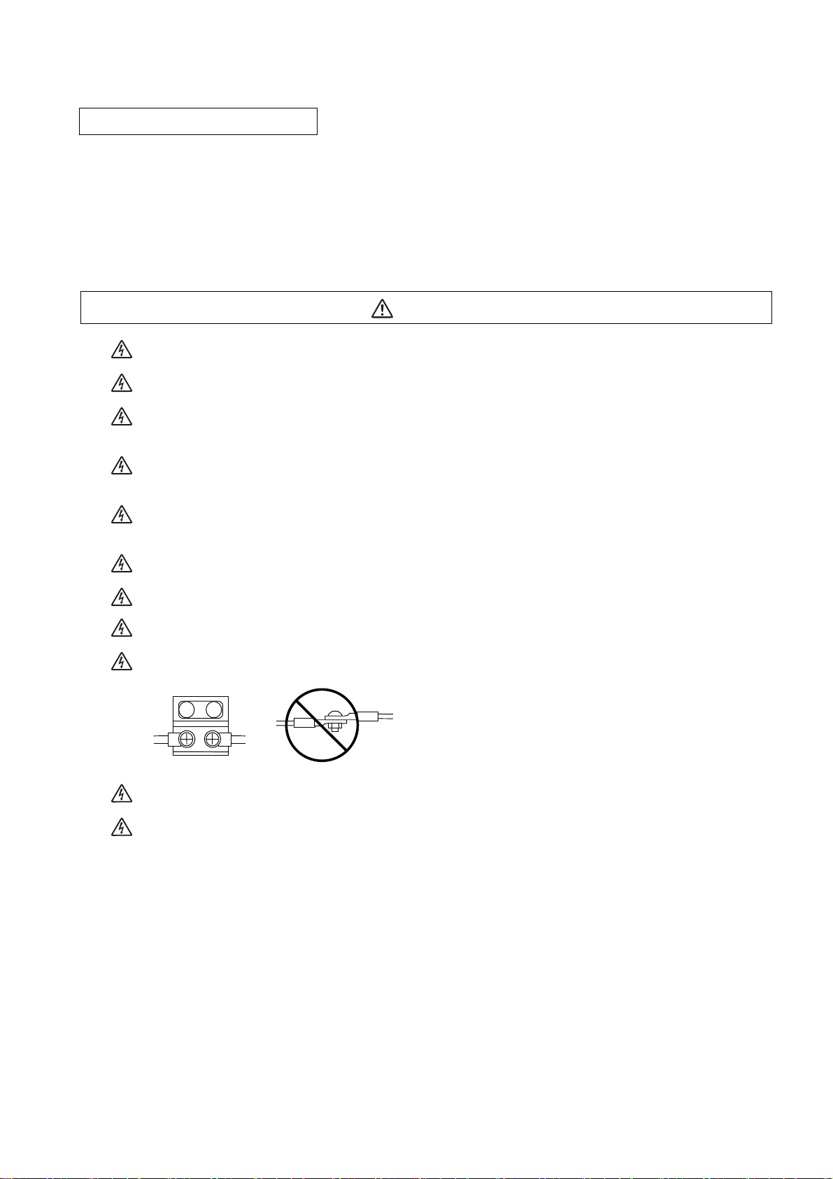
Do not damage, apply excessive stress, place heavy things on or sandwich the cables. Failure to observe
this could result in electric shocks.
Insulate the power lead using a fixed terminal block. Failure to observe this could result in electric shocks.
Completely turn off the all lines of the power supply externally before wiring. Not completely turning off all
power could result in electric shock or damage to the product.
When turning on the power supply or operating the module after wiring, be sure that the module's terminal
covers are correctly attached.
Not attaching the terminal cover could result in electric shock.
Page 10
2. Items related to prevention of fire
CAUTION
Install the controller, drive unit, motor and regenerative resistor on non-combustible material. Installation
directly on or near combustible materials could result in fires.
If any malfunction in the unit is observed, shut off the power at the unit’s power supply side. Continuous
flow of large current could result in fires.
Install an appropriate no fuse breaker (NFB) and contactor (MC) on the power input section of the drive unit
and configure the sequence that shuts the power off upon drive unit’s emergency stop or alarm.
When a breaker is shared for multiple power supply units, the breaker may not function upon short-circuit
failure in a small capacity unit. Do not share a breaker for multiple units as this is dangerous.
Incorrect wiring and connections could cause the devices to damage or burn.
3. Items related to prevention of bodily injury or property damage
DANGER
When transporting or installing a built-in IPM spindle or linear servomotor, be careful so that your hand or
property will not be trapped in the motors or other metal objects. Also keep the devices with low magnetic
tolerance away from the product.
CAUTION
Do not apply voltages to the connectors or terminals other than voltages indicated in the connection and
setup manual for the controller or specifications manual for the drive unit. Failure to observe this could
cause bursting, damage, etc.
Incorrect connections could cause the devices to rupture or damage, etc. Always connect the cables to the
indicated connectors or terminals.
Incorrect polarity (+ -) could cause the devices to rupture or damage, etc.
Persons wearing medical devices, such as pacemakers, must stay away from this unit. The
electromagnetic waves could adversely affect the medical devices.
Fins on the rear of the unit, regenerative resistor and motor, etc., will be hot during operation and for a while
after the power has been turned OFF. Do not touch or place the parts and cables, etc. close to these
sections. Failure to observe this could result in burns.
Do not ent er the ma chine’s movable range during automatic operation. Keep your hands, feet or face away
from the spindle during rotation.
Page 11
4. General precautions
Always follow the precautions below. Incorrect handling could result in faults, injuries or electric shocks, etc.
(1) Items related to product and manual
CAUTION
For items described as "Restrictions" or "Usable State" in this manual, the instruction manual issued by
the machine tool builder takes precedence over this manual.
Items that are not described in this manual must be interpreted as "not possible".
This manual is written on the assumption that all the applicable functions are included.
Some of them, however, may not be available for your NC system.
Refer to the specifications issued by the machine tool builder before use.
For information about each machine tool, refer to manuals issued from the machine tool builder.
Some screens and functions may differ depending on each NC system (or version), and some functions
may not be possible. Please confirm the specifications before starting to use.
Do not connect NC system to the Internet-connected network.
To maintain the safety of the NC system against unauthorized access from external devices via the
network, take appropriate measures.
(2) Transportation and installation
CAUTION
Correctly transport the products according to the mass.
Do not stack the products exceeding the indicated limit.
Do not hold the cables, shaft or detector when transporting the motor.
Do not transport the controller or drive unit by suspending or holding the connected wires or cables.
Do not hold the front cover when transporting the unit, or the front cover could come off, causing the unit
to drop.
Install on a non-combustible place where the unit's or motor's mass can be withstood according to the
instruction manual.
The motor does not have a complete water-proof (oil-proof) structure. Do not allow oil or water to contact
or enter the motor. Prevent the cutting chips from being accumulated on the motor as they easily soak up
oil.
When installing the motor facing upwards, take measures on the machine side so that gear oil, etc., will not
enter the motor shaft.
Do not remove the detector from the motor. (The detector installation screw is treated with sealing.)
Do not allow foreign matters, especially, conductive foreign matters such as screws or metal chips, or
combustible foreign matters such as oil, to enter the controller, drive unit or motor. Failure to observe this
could result in rupture or damage.
Do not get on the product or place heavy objects on it.
Provide prescribed distance between the controller/drive unit and inner surface of the control panel/other
devices.
Do not install or operate the controller, drive unit or motor that is damaged or has missing parts.
Page 12
CAUTION
Take care not to cut hands, etc. with the heat radiating fins or metal edges.
Do not block the intake/outtake ports of the motor with the cooling fan.
Install the controller’s display section and operation board section on the spot where cutting oil will not
reach.
The controller, drive unit and motor are precision devices, so do not drop or apply thumping vibration and
strong impacts on them.
Store and use the units according to the environment conditions indicated in each specifications manual.
When disinfectants or insecticides must be used to treat wood packaging materials, always use methods
other than fumigation (for example, apply heat treatment at the minimum wood core temperature of 56 °C
for a minimum duration of 30 minutes (ISPM No. 15 (2009))).
If products such as units are directly fumigated or packed with fumigated wooden materials, halogen
substances (including fluorine, chlorine, bromine and iodine) contained in fumes may contribute to the
erosion of the capacitors. When exporting the products, make sure to comply with the laws and regulations
of each country.
Do not use the products in conjunction with any components that contain halogenated flame retardants
(bromine, etc). Failure to observe this may cause the erosion of the capacitors.
Securely fix the motor to the machine. The motor could come off during operation if insecurely fixed.
Always install the motor with reduction gear in the designated direction. Failure to observe this could result
in oil leaks.
Always install a cover, etc., over the shaft so that the rotary section of the motor cannot be touched during
motor rotation.
When installing a coupling to the servomotor shaft end, do not apply impacts by hammering, etc. The
detector could be damaged.
Use a flexible coupling when connecting with a ball screw, etc., and keep the shaft core deviation smaller
than the tolerable radial load of the shaft.
Do not use a rigid coupling as an excessive bending load will be applied on the shaft and could cause the
shaft to break.
Do not apply a load exceeding the tolerable level onto the motor shaft. The shaft or bearing could be
damaged.
Before using this product after a long period of storage, please contact the Mitsubishi Service Station or
Service Center.
Following the UN recommendations, battery units and batteries should be transported based on the
international regulations such as those determined by International Civil Aviation Organization (ICAO),
International Air Transport Association (IATA), International Maritime Organization (IMO) and U.S.
Department of Transportation (DOT).
Due to ventilation problems, do not install the base units vertically or horizontally when C80 is mounted on
a board, etc.
Install the basic base on a flat surface. Unevenness or warping of the surface can apply undue force to
printed circuit boards and lead to operation failures.
Avoid installing the base units close to a vibration source, such as a large electromagnetic contactor or nofuse breaker. Install them on a separate panel or at a safe distance.
To limit the effects of reflected noise and heat, leave 100mm(3.94inch) or more clearance to instruments
fitted in front of CNC CPU (on the rear of the door). Similarly, leave 50mm(1.97inch) or more clearance
between instruments and the left and right sides of the basic b
ase.
Page 13
(3) Items related to wiring
RA
RA
COM COM
Control
output
signal
Drive unit
Control
output
signal
Drive unit
(24VDC) (24VDC)
CAUTION
Correctly wire this product. Failure to observe this could result in motor runaway, etc.
Incorrect terminal connections could cause the devices to rupture or damage, etc.
Do not install a phase advancing capacitor, surge absorber or radio noise filter on the output side of the
drive unit.
Correctly connect the output side (terminal U, V, W). The motor will not run properly if incorrectly
connected.
Always install an AC reactor per each power supply unit.
Always install an appropriate breaker per each power supply unit. A breaker cannot be shared for multiple
power supply units.
Do not directly connect a commercial power supply to the motor. Failure to observe this could result in
faults.
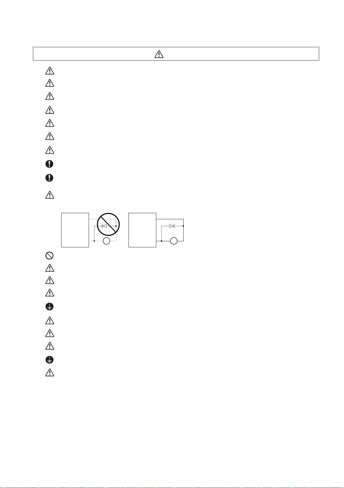
When using an inductive load such as relays, always connect a diode in parallel to the load as a noise
countermeasure.
When using a capacitive load such as a lamp, always connect a protective resistor serially to the load to
suppress rush currents.
Do not mistake the direction of the surge absorption diode to be installed on the DC relay for the control
output signal. If mistaken, the signal will not be output due to fault in the drive unit, and consequently the
protective circuit, such as emergency stop, could be disabled.
Do not connect or disconnect the cables between units while the power is ON.
Do not connect or disconnect the PCBs while the power is ON.
Do not pull the cables when connecting/disconnecting them.
Securely tighten the cable connector fixing screw or fixing mechanism. The motor could come off during
operation if insecurely fixed.
Always treat the shield cables indicated in the Connection Manual with grounding measures such as cable
clamps.
Separate the signal wire from the drive line or power line when wiring.
Carry out wiring so that there is no possibility of short circuit between wires, nor of dangerous state.
Use wires and cables whose wire diameter, heat resistance level and bending capacity are compatible with
the system.
Ground the device according to the requirements of the country where the device is to be used.
Wire the heat radiating fins and wires so that they do not contact.
Page 14
CAUTION
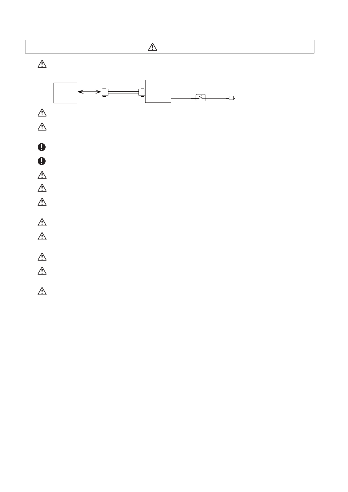
When using the RS-232C device as a peripheral device, caution must be paid for connector connection/
disconnection. Always use a double-OFF type AC power supply switch on the device side, and connect/
disconnect the connector with the AC power supply on the device side OFF.
NC unit
Device
RS-232C
Switch
AC socket
Using a stabilized power supply without overcurrent protection may cause the unit's failure due to
miswiring of 24V.
12V, 5V, and 3.3V output from connectors are to supply the power for dedicated peripheral devices. Do not
use for other equipment to supply the power since we do not guarantee the NC operation by voltage down
or noise sneaking.
When using an inductive load such as a relay, always connect a diode in parallel to the load to prevent a
counter-electromotive force.
When the rush current exceeds the maximum output current, always connect a protective resistor serially
to the load to suppress rush currents.
The wires from the surge absorber should be connected without extensions.
Be sure to ground the earth terminal FG and LG. Not doing so could result in electric shock or operation
failure. (Ground resistance: 100Ω or less)
When wiring in the unit, be sure that it is done correctly by checking the product's rated voltage and the
terminal layout. Connecting a power supply that is different from the rating or incorrectly wiring the product
could result in fire or damage.
External connections shall be crimped or pressure welded with the specified tools, or correctly soldered.
Imperfect connections could result in short circuit, fire, or operation failure.
Tighten the terminal screws within the specified torque range. If the terminal screws are loose, it could
result in short circuit, fire, or operation failure. Tightening the terminal screws too far may cause damages
to the screws and/or the module, resulting in drop, short circuit, or operation failure.
Be sure there are no foreign matters such as sawdust or wiring debris inside the module. Such debris could
cause fire, damage, or operation failure.
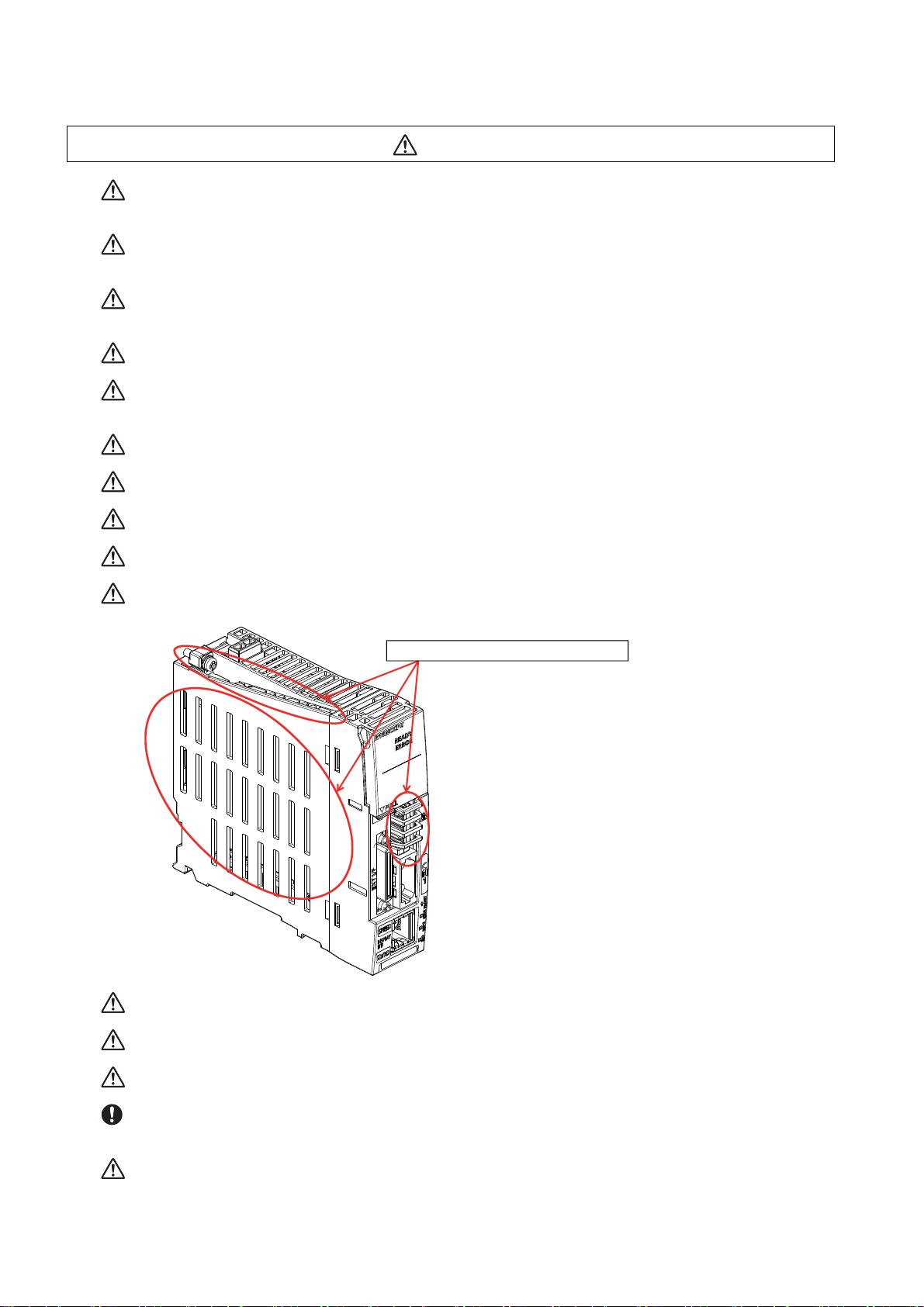
The module has an ingress prevention label on its top to prevent foreign matter, such as wiring debris, from
entering the module during wiring. Do not remove this label during wiring. Before starting system
operation, be sure to remove this label because of heat dissipation.
When connecting to a personal computer and a unit with the USB interface, an electric shock or a unit
failure may occur.
Operate these correctly according to the manual of a unit and a personal computer.
Observe the following cautions when a personal computer in an AC power supply is used.
(1) For a personal computer that uses a 3-pin power plug or power plug with a ground lead type, make sure
to use a plug socket including a ground input electrode or ground the earth lead, respectively.
And, ensure to ground a personal computer and a unit. (Ground resistance: 100Ω or less)
(2) For a personal computer that uses a 2-pin power plug without ground lead, make sure to connect the
unit to the personal computer according to the following procedures. And, it is recommended to supply the
same power supply line to a personal computer and the unit.
(a) Pull out the power plug of the personal computer from the AC outlet.
(b) Confirm that the power plug of the personal computer has been pulled out from the AC outlet, and
connect USB cables, the extension cable or the bus connection cable of a GOT.
(c) Insert the power plug of the personal computer into the AC outlet.
Page 15

(4) Set up
WARNING
Do not cancel the emergency stop before confirming the basic operation.
Always set the stroke end and stroke limit. Failure to set this could result in collision with the machine end.
CAUTION
If the descriptions relating to the "restrictions" and "allowable conditions" conflict between this manual
and the machine tool builder's instruction manual. the latter has priority over the former.
The operations to which no reference is made in this manual should be considered "impossible".
This manual is written on the assumption that all the applicable functions are included.
Some of them, however, may not be available for your NC system.
Refer to the specifications issued by the machine tool builder before use.
Some screens and functions may differ depending on each NC system (or version), and some functions
may not be possible. Please confirm the specifications before starting to use.
If the battery low warning is issued, save the machining programs, tool data and parameters in an input/
output device, and then replace the battery. When the battery alarm is issued, the machining programs,
tool data and parameters may have been destroyed. Replace the battery and then reload the data.
Do not adjust the spindle when possible risks associated with adjustment procedures are not thoroughly
taken into consideration.
Be careful when touching spindle's rotating section, or your hand may be caught in or cut.
It is dangerous to restore the backup data of other machine when the absolute position is established
because the zero point will be established with the absolute position of the linear axis rewritten, thus the
zero point position is off the right position.
Initialize the zero point again.
Restoration by SRAM data is available only if the rotary axis motor has not rotated in a same direction
30,000 times or more since the acquisition of the data.
Otherwise, the zero point of the rotary axis will change by turning the power OFF and ON after writing the
SRAM data, which will cause danger. Make sure the zero point is not off the right position.
The use of this method should be limited to when necessary, such as when replacing an NC unit, and
requires enough safety confirmation before executing.
(5) Operation and adjustments
CAUTION
If the operation start position is set in a block which is in the middle of the program and the program is
started, the program before the set block is not executed. Please confirm that G and F modal and
coordinate values are appropriate. If there are coordinate system shift commands or M, S, T and B
commands before the block set as the start position, carry out the required commands using the MDI, etc.
If the program is run from the set block without carrying out these operations, there is a danger of
interference with the machine or of machine operation at an unexpected speed, which may result in
breakage of tools or machine tool or may cause damage to the operators.
Under the constant surface speed control (during G96 modal), if the axis targeted for the constant surface
speed control moves toward the spindle center, the spindle rotation speed will increase and may exceed
the allowable speed of the workpiece or chuck, etc. In this case, the workpiece, etc. may jump out during
machining, which may result in breakage of tools or machine tool or may cause damage to the operators.
Check and adjust programs and each parameter before starting operation. Failure to observe this could
result in unpredictable operations depending on the machine.
Do not make drastic adjustments or changes in the parameters as the operation could become unstable.
In the explanation on bits, set all bits not used, including blank bits, to "0".
Page 16
(6) Usage
The metal part becomes the high temperature.
CAUTION
Use C80 in an environment that meets the general specifications contained in this manual. Using C80 in an
environment outside the range of the general specifications could result in electric shock, fire, operation
failure, and damage to or deterioration of the product.
When mounting the module, be sure to insert the module fixing hook on the module's bottom into the
module fixing hole on the base unit. Incorrect mounting could cause an operation failure or a damage/drop
of the unit.
Hold down the module loading lever at the module bottom and securely insert the fixing hook into the fixing
hole in the base unit. Install the module with the module fixing hole as a supporting point. Incorrect
mounting could cause an operation failure or a damage/drop of the unit.
Be sure to fix all the modules with screws to prevent them from dropping. The fixing screws (M3 x 12) are
to be prepared by user.
Tighten the screw in the specified torque range. Under tightening may cause a drop, short circuit or
operation failure. Over tightening may cause a drop, short circuit or operation failure due to damage to the
screw or module.
Be sure to install the extension cable to connectors of the basic base unit correctly. After installation,
check them for looseness. Poor connections could cause an input or output failure.
Completely turn off all lines of external power supply used in the system before loading or unloading the
module. Not doing so could result in electric shock or damage to the product.
Do not mount/dismount the modules or base over 50 times. Mounting/dismounting over 50 times may
cause an operation failure.
Do not directly touch the module's conductive parts or electronic parts. Touching these parts could cause
an operation failure or give damage to the module.
Do not touch the radiating fin of the CNC CPU module while an electric current is supplied or in a short
while after the power OFF. Touching the fin may cause burns. Take care when removing the unit.
When removing the unit, always remove the fixing screws and then take the fixing hook out from the fixing
hole. Incorrect removal will damage the module fixing hook.
When the module fixing screws are used, remove the screws first and module from the base unit. Failure
to do so may damage the module.
The module surface temperature may be high immediately after power-off. When the module is removed,
pay attention to the burn injury.
Install an external emergency stop circuit so that the operation can be stopped and the power turns OFF
immediately when unforeseen situation occurs. A contactor, etc., is required in addition to the shutoff
function mounted in the controller.
Turn OFF the power immediately if any smoke, abnormal noise or odor is generated from the controller,
drive unit or motor.
Page 17

CAUTION
MBR EMG
Motor
Electromagnetic
brake
Shut off with motor
brake control output
Shut off with CNC brake
control PLC output
24VDC
Only a qualified technician may disassemble or repair this product.
Do not alter.
Use a noise filter, etc. to reduce the effect of electromagnetic disturbances in the case where
electromagnetic disturbances could adversely affect the electronic devices used near the drive unit.
Use the drive unit, motor and each regenerative resistor with the designated combination. Failure to
observe this could result in fires or faults.
The combination of the motor and drive unit that can be used is determined. Be sure to check the models
of motor and drive unit before test operation.
The brakes (electromagnetic brakes) mounted in the servomotor are used for the purpose of holding, and
must not be used for normal braking. Also, do not run the motor with the motor brake applied. Motor brake
is used for the purpose of holding.
For the system running via a timing belt, install a brake on the machine side so that safety can be ensured.
Be sure to confirm SERVO OFF (or READY OFF) when applying the electromagnetic brake. Also, be sure
to confirm SERVO ON prior to releasing the brake.
When using the DC OFF type electromagnetic brake, be sure to install a surge absorber on the brake
terminal.
Do not connect or disconnect the cannon plug while the electromagnetic brake’s power is ON. The cannon
plug pins could be damaged by sparks.
After changing programs/parameters, or after maintenance/inspection, always carry out a test operation
before starting actual operation.
Use the power that are complied with the power specification conditions (input voltage, input frequency,
tolerable instantaneous power failure time) indicated in each specifications manual.
When making detector cables, do not mistake connection. Failure to observe this could result in
malfunction, runaway or fire.
(7) Troubleshooting
Use a motor with electromagnetic brakes or
establish an external brake mechanism for
the purpose of holding; this serves as
countermeasures for possible hazardous
situation caused by power failure or
product fault.
Use a double circuit structure for the
electromagnetic brake's operation circuit
so that the brakes will activate even when
the external emergency stop signal is
issued.
The machine could suddenly restart when the power is restored after an instantaneous power failure, so
stay away from the machine. (Design the machine so that the operator safety can be ensured even if the
machine restarts.)
To secure the absolute position, do not shut off the servo drive unit’s control power supply when its battery
voltage drops (warning 9F) in the servo drive unit side.
If the battery voltage drop warning alarm occurs in the controller side, make sure to back up the machining
programs, tool data and parameters, etc. with the input/output device before replacing the battery.
Depending on the level of voltage drop, memory loss could have happened. In that case, reload all the data
backed up before the alarm occurrence.
CAUTION
Page 18
(8) Maintenance, inspection and part replacement
CAUTION
Periodically back up the programs, tool data and parameters to avoid potential data loss. Also, back up
those data before maintenance and inspections.
The electrolytic capacitor’s capacity will drop due to deterioration. To prevent secondary damage due to
capacitor’s faults, Mitsubishi recommends the electrolytic capacitor to be replaced approx. every five
years even when used in a normal environment. Contact the Service Center or Service Station for
replacements.
Do not perform a megger test (insulation resistance measurement) during inspection.
Do not replace parts or devices while the power is ON.
Do not short-circuit, charge, overheat, incinerate or disassemble the battery.
Be careful not to break the heat radiating fins during maintenance or replacement.
(9) Disposal
CAUTION
Take the batteries, etc., off from the controller, drive unit and motor, and dispose of them as general
industrial wastes.
Do not alter or disassemble controller, drive unit, or motor.
Collect and dispose of the spent batteries according to the local laws.
(10) General precautions
To explain the details, drawings given in the instruction manual, etc., may show the unit with the cover
or safety partition removed. When operating the product, always place the cover or partitions back to
their original position, and operate as indicated in the instruction manual, etc.
Page 19

Page 20

Treatment of waste
The following two laws will apply when disposing of this product. Considerations must be made to each law.
The following laws are in effect in Japan. Thus, when using this product overseas, the local laws will have a
priority. If necessary, indicate or notify these laws to the final user of the product.
(1) Requirements for "Law for Promotion of Effective Utilization of Resources"
(a) Recycle as much of this product as possible when finished with use.
(b) When recycling, often parts are sorted into steel scraps and electric parts, etc., and sold to scrap
contractors. Mitsubishi recommends sorting the product and selling the members to appropriate
contractors.
(2) Requirements for "Law for Treatment of Waste and Cleaning"
(a) Mitsubishi recommends recycling and selling the pr oduct when n o longer needed a ccording to item
(1) above. The user should make an effort to reduce waste in this manner.
(b) When disposing a product that cannot be resold, it shall be treated as a waste product.
(c) The treatment of industrial waste must be commissioned to a licensed industrial waste treatment
contractor, and appropriate measures, including a manifest co ntrol, must be taken.
(d) Batteries correspond to "primary batteries", and must be disposed of according to local disposal
laws.
Page 21

Page 22

Disposal
(Note) This symbol mark is for EU countries only.
This symbol mark is according to the directive 2006/66/EC Article 20 Information for endusers and Annex II.
Your MITSUBISHI ELECTRIC product is designed and manufactured with high quality materials and
components which can be recycled and/or reused.
This symbol means that batteries and accumulators, at their end-of-life, should be disposed of
separately from your household waste.
If a chemical symbol is printed beneath the symbol shown above, this chemical symbol means that the
battery or accumulator contains a heavy metal at a certain concentration. This will be indicated as
follows:
Hg: mercury (0,0005%), Cd: cadmium (0,002%), Pb: lead (0,004%)
In the European Union there are separate collection systems for used batteries and accumulators.
Please, dispose of batteries and accumulators correctly at your local community waste collection/
recycling centre.
Please, help us to conserve the environment we live in!
Page 23

Page 24

Trademarks
MELDAS, MELSEC, EZSocket, EZMotion, iQ Platform, MELSEC iQ-R, MELSOFT, GOT, CC-Link, CC-Link/LT,
CC-Link IE, CC-Link IE/field, EcoMonitorLight and SLMP are either trademarks or registered trademarks of
Mitsubishi Electric Corporation in Japan and/or other countries.
Ethernet is a registered trademark of Xerox Corporation in the United States and/or other countries.
Microsoft®, Windows®, SQL Server® and Access® are either trademarks or registered trademarks of Microsoft
Corporation in the United States and/or other countries.
SD logo and SDHC logo are either registered trademarks or trademarks of LLC.
UNIX is a registered trademark of The Open Group in the United States and/or other countries.
Intel® and Pentium® are either trademarks or registered trademarks of Intel Corporation in the United States and/or
other countries.
MODBUS® is either a trademark or a registered trademark of Schneider Electric USA, Inc. or the affiliated
companies in Japan and/or other countries.
EtherNet/IP is a trademark of Open DeviceNet Vendor Association,Inc.
PROFIBUS-DP and PROFINET are either trademarks of Profibus International.
Oracle® is a registered trademark of Oracle Corporation, the subsidiaries, or the affiliated companies in the United
States and /or other countries.
VNC is a registered trademark of RealVNC Ltd. in the United States and other countries.
Other company and product names that appear in this manual are trademarks or registered trademarks of the
respective companies.
Page 25

Page 26

本製品の取扱いについて
( 日本語 /Japanese)
本製品は工業用 ( クラス A) 電磁環境適合機器です。販売者あるいは使用者はこの点に注意し、住商業環境以外で
の使用をお願いいたします。
Handling of our product
(English)
This is a class A product. In a domestic environment this product may cause radio interference in which case the
user may be required to take adequate measures.
본 제품의 취급에 대해서
( 한국어 /Korean)
이 기기는 업무용 (A 급 ) 전자파적합기기로서 판매자 또는 사용자는 이 점을 주의하시기 바라며 가정외의 지역에
서 사용하는 것을 목적으로 합니다 .
Page 27

Page 28

Contents
1 System Basic Configuration ....................................................................................................................... 1
1.1 System Basic Configuration Drawing..................................................................................................... 2
2 General Connection Diagram...................................................................................................................... 3
3 List of Configuration.................................................................................................................................... 5
3.1 CNC Control Unit ................................................................................................................................... 6
3.2 GOT ..................................................................................................................................................... 16
3.2.1 GT27............................................................................................................................................ 16
3.2.2 GT25............................................................................................................................................ 18
3.3 Peripheral Device................................................................................................................................. 19
3.4 Dual Signal Module.............................................................................................................................. 19
3.5 List of Q Series Units (for RQ extension base unit) ............................................................................. 20
4 General Specifications .............................................................................................................................. 23
4.1 Installation Environment Conditions..................................................................................................... 24
4.2 Base Unit ............................................................................................................................................. 25
4.2.1 Basic Base Unit............................................................................................................................ 25
4.2.2 Extension Base Unit..................................................................................................................... 26
4.2.3 RQ Extension Base Unit .............................................................................................................. 28
4.3 Power Supply....................................................................................................................................... 29
4.3.1 R61P/R62P/R63P/R64P .............................................................................................................. 29
4.3.2 Q61P/Q63P/Q64PN..................................................................................................................... 33
4.4 PLC CPU ............................................................................................................................................. 38
4.5 CNC CPU Module................................................................................................................................ 43
4.6 Dual Signal Module.............................................................................................................................. 47
4.7 Signal Splitter....................................................................................................................................... 52
4.8 Manual Pulse Generator ...................................................................................................................... 54
4.8.1 5V Manual Pulse Generator (UFO-01-2Z9) ................................................................................. 54
4.8.2 12V Manual Pulse Generator (HD60C) ......................................................................................55
4.9 Recommended Terminal Block for Dual Signal Module ...................................................................... 55
4.10 GOT (Panel Cut Dimensions) ............................................................................................................ 56
5 Installation .................................................................................................................................................. 57
5.1 Module Installation ............................................................................................................................... 58
5.1.1 Precautions for Handling................................................................................................
Precautions for Installation of Basic Base Unit ............................................................................ 61
5.1.2
5.1.3 Module Installation and Removal................................................................................................. 63
5.1.4 Installation and Removal the Signal Splitter ................................................................................ 66
5.2 Calculating Heat Generation by C80 ................................................................................................... 68
6 Wiring and Connecting.............................................................................................................................. 71
6.1 Precautions .......................................................................................................................................... 72
6.1.1 Precautions for Power Supply Wiring .......................................................................................... 72
6.1.2 Precautions for Wiring of I/O Equipment...................................................................................... 73
6.1.3 Precautions for Grounding........................................................................................................... 73
6.1.4 Precautions for Using Optical Communication Cable.................................................................. 74
6.2 Wiring to the Power Supply Module..................................................................................................... 76
6.2.1 R61P/R62P/R63P/R64P .............................................................................................................. 76
6.2.2 Q61P/Q63P/Q64PN..................................................................................................................... 77
6.3 Connecting the Emergency Stop Signal .............................................................................................. 78
6.4 Connecting the GOT ............................................................................................................................ 79
6.5 Connecting the Drive Unit .................................................................................................................... 80
6.6 Connecting the Dual Signal Module..................................................................................................... 81
6.7 Connecting the Signal Splitter.............................................................................................................. 82
6.8 Connecting the Skip Signal (Sensor) ................................................................................................... 83
6.9 Connecting the Manual Pulse Generator............................................................................................. 84
.............. 58
Page 29

7 Cable ........................................................................................................................................................... 87
7.1 Symbols for Writing Cable Drawings.................................................................................................... 88
7.2 Cables for CNC CPU ........................................................................................................................... 89
7.2.1 F020/F021/F022 Cable ................................................................................................................ 89
7.2.2 G020/G021/G022 Cable .............................................................................................................. 90
7.2.3 H010 Cable .................................................................................................................................. 91
7.2.4 H101 Cable .................................................................................................................................. 92
7.2.5 H300 Cable .................................................................................................................................. 93
7.2.6 H310 Cable .................................................................................................................................. 94
7.2.7 H401 Cable .................................................................................................................................. 95
7.2.8 H501 Cable .................................................................................................................................. 95
7.2.9 J303 Cable................................................................................................................................... 96
7.3 Cable Relating to Drive Unit................................................................................................................. 97
7.3.1 Cable Wire and Assembly............................................................................................................ 97
7.3.2 CNP2E-1 Cable ........................................................................................................................... 98
7.3.3 CNP3EZ-2P/CNP3EZ-3P Cable .................................................................................................. 99
7.3.4 CNV2E-8P/CNV2E-9P Cable .................................................................................................... 100
7.3.5 CNV2E-D Cable......................................................................................................................... 101
7.3.6 CNV2E-HP Cable ...................................................................................................................... 102
7.3.7 DG30 Cable ............................................................................................................................... 103
7.3.8 G380 Cable................................................................................................................................ 104
7.3.9 J395 Cable................................................................................................................................. 105
7.3.10 J396 Cable............................................................................................................................... 106
7.3.11 MR-BKS1CBL-A1-H / MR-BKS1CBL-A2-H Cable................................................................... 107
7.3.12 MR-BT6V2CBL Cable.............................................................................................................. 107
7.3.13 MR-D05UDL3M-B Cable ......................................................................................................... 108
7.3.14 MR-PWS1CBL-A1-H / MR-PWS1CBL-A2-H Cable ................................................................. 108
7.3.15 SH21 Cable.............................................................................................................................. 109
8 Setup Outline............................................................................................................................................ 111
8.1 Flow of the Initial Setup...................................................................................................................... 112
9 GOT Initial Setup ...................................................................................................................................... 113
9.1 GT Designer3..................................................................................................................................... 114
9.1.1 Installing GT Designer3 ..................................
9.1.2 Making Communication Settings ............................................................................................... 115
9.1.2.1 Setting Ethernet Connection.............................................................................................. 115
9.1.3 Setting the Saving Destination Drive for Backup Data............................................................... 122
9.1.4 Setting Time on GOT ................................................................................................................. 124
9.1.5 Creating a GOT Screen ............................................................................................................. 126
9.1.5.1 Precautions for Device Settings......................................................................................... 126
9.1.5.2 Special Function Switch..................................................................................................... 127
9.1.6 Writing the Package Data to GOT ............................................................................................. 128
10 PLC CPU Initial Setup ............................................................................................................................ 133
10.1 GX Works3....................................................................................................................................... 134
10.1.1 Connecting the Devices Necessary for Setup ......................................................................... 134
10.1.2 Setting the Connection to GX Works3 ..................................................................................... 135
10.1.3 Setting Multi-CPU Parameters................................................................................................. 137
10.1.4 Writing the Created Parameters to the PLC ............................................................................ 148
11 CNC CPU Initial Setup ........................................................................................................................... 149
11.1 Initializing CNC CPU Internal Data (Clearing SRAM Data).............................................................. 150
11.1.1 Loss and Restoration of Absolute Position Data...................................................................... 151
11.2 Selecting NC System Type and Display Language ......................................................................... 153
11.3 Setting Multi-CPU Parameters ......................................................................................................... 155
11.4 Setting the Date and Time ............................................................................................................... 170
................................................................
........... 114
12 Setting Machine Parameters ................................................................................................................. 171
12.1 Setting the Parameters for the System Specifications ..................................................................... 172
Page 30

12.2 Setting the Parameters for the Machine Specifications ................................................................... 173
12.3 Setting Drive Unit MDS-E/EH Series ............................................................................................... 175
12.3.1 Setting the Rotary Switch......................................................................................................... 175
12.3.2 Setting DIP Switch ................................................................................................................... 176
12.4 Setting Drive Unit MDS-EM/EMH Series ......................................................................................... 177
12.4.1 Setting the Rotary Switch......................................................................................................... 177
12.5 Setting Drive Unit MDS-EJ/EJH Series............................................................................................ 178
12.5.1 Setting the Rotary Switch......................................................................................................... 178
12.5.2 Setting the DIP Switch ............................................................................................................. 179
12.6 Setting Up without Connecting to the Motor/Drive Units at the Startup of Drive Unit ...................... 180
12.7 Servo Simplified Adjustment ............................................................................................................ 181
12.7.1 First Measure Against Vibration............................................................................................... 181
12.7.2 NC Analyzer2........................................................................................................................... 182
13 Setting of Inter-CPU Features ............................................................................................................... 183
13.1 Setting to Share Handles between CNC CPU Modules .................................................................. 184
14 Setting the Position Detection System ................................................................................................ 185
14.1 Adjusting the Absolute Position Detection System ..........................................................................186
14.1.1 Basic Position Alignment Method I .......................................................................................... 188
14.1.2 Basic Position Alignment Method II ......................................................................................... 191
14.1.3 Machine End Stopper Method: Automatic Initialization............................................................ 193
14.1.4 Machine End Stopper Method: Manual Initialization................................................................ 197
14.1.5 Dog-type .................................................................................................................................. 200
14.1.6 Precautions Common for the Initilization Operation................................................................. 200
14.1.7 Precautions Common for the Dogless-type Absolute Position Detector.................................. 201
14.2 Adjustment of Reference Position Return in Relative Position Detection System ........................... 202
14.2.1 Dog-type Reference Position Return Operation ..................................................................... 202
14.2.2 Dog-type Reference Position Return Adjustment Procedures ................................................. 203
15 Setting the Tool Entry Prohibited Range ........................................................................................... 209
15.1 Stroke End (H/W OT)....................................................................................................................... 210
15.2 Stored Stroke Limit (S/W OT) .......................................................................................................... 211
15.2.1 Outline ..................................................................................................................................... 211
15.2.2 Stored Stroke Limit I ...................................
15.2.3 Stored Stroke Limit II ............................................................................................................... 215
15.2.4 Stored Stroke Limit IB .............................................................................................................. 217
15.2.5 Stored Stroke Limit IC.............................................................................................................. 218
15.2.6 Movable Range during Inclined Axis Control ........................................................................... 219
15.2.7 Stored Stroke Limit for Rotation Axis ....................................................................................... 220
15.2.8 Changing the Area for the Stored Stroke Limit I ...................................................................... 220
15.2.9 Precautions .............................................................................................................................. 221
16 Setting the Deceleration Check ............................................................................................................ 223
16.1 Function ........................................................................................................................................... 224
16.2 Deceleration Check Method............................................................................................................. 226
16.3 Deceleration Check for Opposite Direction Movement Reversal..................................................... 228
16.4 Parameter ........................................................................................................................................ 229
16.5 Relation with Other Functions.......................................................................................................... 231
16.6 Precautions ...................................................................................................................................... 232
17 Data Backup and Restoration ............................................................................................................... 233
17.1 Backup ............................................................................................................................................. 235
17.2 Restoration....................................................................................................................................... 237
................................................................
............. 214
18 Appx.1: Protection Setting .................................................................................................................... 239
18.1 Protect Setting Screen ..................................................................................................................... 240
18.2 Returning the Password to the Non-input State (Operation level 0 to 3) ......................................... 242
18.3 Changing the Operation Level to One of 4 to 6 ............................................................................... 242
18.4 Changing the Password................................................................................................................... 243
Page 31

18.5 Clearing the Password ..................................................................................................................... 244
18.6 Changing the Protection Level ......................................................................................................... 245
18.7 Saving the Protection Level Setting ................................................................................................. 245
19 Appx.2: EMC Installation Guidelines.................................................................................................... 247
19.1 Introduction ...................................................................................................................................... 248
19.2 EMC Directives ................................................................................................................................ 248
19.3 EMC Measures ................................................................................................................................ 249
19.4 Panel Structure ................................................................................................................................ 249
19.4.1 Measures for Control Panel Body ............................................................................................ 249
19.4.2 Measures for Door ................................................................................................................... 250
19.4.3 Measures for Power Supply..................................................................................................... 250
19.5 Measures for Wiring in Panel ........................................................................................................... 251
19.5.1 Precautions for Wiring in Panel................................................................................................ 251
19.5.2 Shield Treatment of Cables ..................................................................................................... 252
19.6 EMC Countermeasure Parts ............................................................................................................ 253
19.6.1 Shield Clamp Fitting................................................................................................................. 253
19.6.2 Ferrite Core.............................................................................................................................. 254
19.6.3 Surge Absorber........................................................................................................................ 256
19.6.4 Selection of Stabilized Power Supply ...................................................................................... 258
20 Appx.3: Restrictions for Lithium Batteries .......................................................................................... 259
20.1 Restriction for Packing ..................................................................................................................... 260
20.1.1 Target Products ....................................................................................................................... 260
20.1.2 Handling by User ..................................................................................................................... 261
20.1.3 Reference ................................................................................................................................ 261
20.2 Products Information Data Sheet (ER Battery) ................................................................................ 262
20.3 Forbiddance of Transporting Lithium Battery
by Passenger Aircraft Provided in the Code of Federal Regulation................................................. 264
20.4 California Code of Regulation "Best Management Practices for Perchlorate Materials" ................. 264
20.5 Restriction Related to EU Battery Directive ..................................................................................... 265
20.5.1 Important Notes ....................................................................................................................... 265
20.5.2 Information for End-user ...............................................................................................
........... 265
Appx.4: Precautions for Compliance to UL/c-UL Standards ............................................................. 267
21
Page 32

1
IB-1501452-C
1
System Basic Configuration
Page 33

C80 Series Connection and Setup Manual
1 System Basic Configuration
CNC CPU
R16NCCPU
RnCPU
LED
GT Designer3
GX Works3
NC Analyzer2
EMG
SKIP
MPG
GOT2000 Series
(SVGA, VGA)
SD card
Ethernet connection
PLC CPU
Rotary switch
Optical communication
Drive unit
1.1 System Basic Configuration Drawing
(Note) The supported versions of the GT Designer3 are as follows:
SVGA: Version 1.155M or later
VGA: Version 1.165X or later
GX Works3 Version 1.025B or later is required.
IB-1501452-C
2
Page 34

3
IB-1501452-C
2
General Connection Diagram
Page 35

C80 Series Connection and Setup Manual
2 General Connection Diagram
EMG
FG
RlO1
PLCIO
NCIO
RIO2
EMG DISPLAY I/F
MPG
CN1
EXT l/F
RlO
MPG#1
ACIN/DCIN
AC/DC
H300
H010
H401
H101
H501
H501
R16NCCPU
J303
FA-CBLxxFMV-M
R173SXY
MPG#3MPG#2
RlO1
PLCIO
NCIO
RIO2
R173SXY
RlO1
PLCIO
NCIO
RIO2
R173SXY
H501
SKIP
TU l/F
SW
MPG TERMINAL DCIN
H310
MPG#2
MPG#3
MPG#1
DClN
DClN
FA-TBS40P
FA-TBS40P
Machine I/O
/Operation panel
Manual Pulse Generator
Drive Units
Power
Unit
MELSEC iQ-R I/O Module
/ Intelligent Module
CPU Module
/ Network Module
UFO-01-2Z9 (5VDC)
(Note1)
cable
(Max:20m)
cable
(Max:0.5m)
cable
(Max:20m)
cable
Cable
cable
(Max:20m)
cable
(Max:5m)
Cable
G020 (5VDC, 1ch, Max:15m)
G021 (5VDC, 2ch, Max:15m)
G022 (5VDC, 3ch, Max:15m)
F020 (12VDC, 1ch, Max:45m)
F021 (12VDC, 2ch, Max:45m)
F022 (12VDC, 3ch, Max:45m)
Dotted lines indicate the sections prepared by the machine tool builder.
Used with connector. Cannot be used with cable H300 at the same time
Cable for terminal block
(Max:5m)
Terminal block type
24VDC
24VDC or
100 to 240VAC
Source Power
UFO-01-2Z9 (5VDC)
24VDC
Dual Signal Module
Terminal block type
24VDC
Display module
GOT2000 Series
HD60C (12VDC)
(Max:20m)
PLC
CPU
Module
CPU/
Net-
work
Module
#1
Dual
Signal
Module
CNCCPU
Module
Manual Pulse Generator 3CH
SKIP signals. 4 points (24VDC)
/ Manual Pulse Generator 2CH
Specifications including unit names, cable
names, and maximum lengths of cables are
subject to change without notice. Always
confirm these details before placing an order.
cable
24VDC or
100 to 240VAC
Basic
Base
CPU/
Net-
work
Module
#2
Dual
Signal
Module
Dual
Signal
Module
I/O
Module
#5
I/O
Module
#4
I/O
Module
#3
I/O
Module
#2
I/O
Module
#1
I/O
Module
#6
G380 (Max:30m, for wiring outside the panel)
J395 (Max:10m, for wiring outside the panel)
J396 (Max:10m, for wiring inside the panel)
cable
Signal splitter
FCU7-HN387
SKIP
signals. 4 points (24VDC)
cable
(Max:15m)
24VDC (Not used)
(12VDC) (Note1)
(Note 1) HD60C (12VDC) requires another power source 12VDC.
(Note 2) A CPU module can be mounted on the CPU slot of the base unit or the slot No. 0 to 6. A slot between CPU
modules can be left empty for reservation. Note that you cannot mount an I/O module or intelligent function
module on a slot between CPU modules.
IB-1501452-C
4
Page 36

5
IB-1501452-C
3
List of Configuration
Page 37

C80 Series Connection and Setup Manual
3 List of Configuration
3.1 CNC Control Unit
(1) Basic base
Model name Remarks Reference
R35B 5 slots: for mounting MELSEC iQ-R series module
R38B 8 slots: for mounting MELSEC iQ-R series module
R312B 12 slots: for mounting MELSEC iQ-R series module
(2) Power supply
Model name Remarks Reference
R61P AC power supply module input: AC100 to 240V, output: DC5V/6.5A
R62P
R63P DC power supply module input: DC24V, output: DC5V/6.5A
R64P AC power supply module input: AC100 to 240V, output: DC5V/9A
AC power supply module input: AC100 to 240V, output: DC5V/3.5A, DC24V/
0.6A
(3) PLC CPU
Model name Remarks Reference
R04CPU
R08CPU
R16CPU
R32CPU
R120CPU
Program capacity: 40k steps, Elementary operation processing speed (LD
command): 0.98ns
Program capacity: 80k steps, Elementary operation processing speed (LD
command): 0.98ns
Program capacity: 160k steps, Elementary operation processing speed (LD
command): 0.98ns
Program capacity: 320k steps, Elementary operation processing speed (LD
command): 0.98ns
Program capacity: 1200k steps, Elementary operation processing speed (LD
command): 0.98ns
MELSEC iQ-R Module
Configuration Manual
(SH(NA)-081262)
MELSEC iQ-R Module
Configuration Manual
(SH(NA)-081262)
MELSEC iQ-R CPU Module
User's Manual (Startup)
(SH(NA)-081263)
MELSEC iQ-R CPU Module
User's Manual (Application)
(SH(NA)-081264)
(4) CNC CPU module
Model name Remarks
R16NCCPU CNC CPU module
(5) Input module
(a) AC
Model name Remarks Reference
RX10 AC input: 16 points, AC100 to 120V (50/60Hz)
MELSEC iQ-R I/O Module User's
Manual (SH(NA)-081247)
(b) DC (positive/negative common type)
Model name Remarks Reference
RX40C7 DC input: 16 points, DC24V, 7.0mA
RX41C4 DC input: 32 points, DC24V, 4.0mA
RX42C4 DC input: 64 points, DC24V, 4.0mA
MELSEC iQ-R I/O Module User's
Manual (SH(NA)-081247)
IB-1501452-C
6
Page 38

C80 Series Connection and Setup Manual
3 List of Configuration
(6) Analog input module
(a) Voltage input module
Model name Remarks Reference
MELSEC iQ-R Analog-Digital
Converter Module User's Manual
(Startup) (SH(NA)-081232)
MELSEC iQ-R Analog-Digital
Converter Module User's Manual
(Application) (SH(NA)-081233)
R60ADV8
Voltage input module: 8CH
DC-10 to 10V/-32000 to 32000 80μs/CH
(b) Current input module
Model name Remarks Reference
MELSEC iQ-R Analog-Digital
Converter Module User's Manual
R60ADI8
Current input module: 8CH
DC0 to 20mA/0 to 32000 80μs/CH
(Startup) (SH(NA)-081232)
MELSEC iQ-R Analog-Digital
Converter Module User's Manual
(Application) (SH(NA)-081233)
(c) Voltage/current input module
Model name Remarks Reference
MELSEC iQ-R Analog-Digital
Converter Module User's Manual
(Startup) (SH(NA)-081232)
MELSEC iQ-R Analog-Digital
Converter Module User's Manual
(Application) (SH(NA)-081233)
R60AD4
Voltage/current input module: 4CH
DC-10 to 10V/-32000 to 32000、DC0 to 20mA/0 to 32000 80μs/CH
(7) Output module
(a) Relay
Model name Remarks Reference
RY10R2 Relay output: 16 points, DC24V/2A, AC240V/2A
MELSEC iQ-R I/O Module User's
Manual (SH(NA)-081247)
(b) Transistor (sink type)
Model name Remarks Reference
RY40NT5P Transistor (sink type) output: 16 points, DC12 to 24V, 0.5A
RY41NT2P Transistor (sink type) output: 32 points, DC12 to 24V, 0.2A
RY42NT2P Transistor (sink type) output: 64 points, DC12 to 24V, 0.2A
MELSEC iQ-R I/O Module User's
Manual (SH(NA)-081247)
(c) Transistor (independent)
Model name Remarks Reference
RY40PT5P Transistor (source type) output: 16 points, DC12 to 24V, 0.5A
RY41PT1P Transistor (source type) output: 32 points, DC12 to 24V, 0.1A
RY42PT1P Transistor (source type) output: 64 points, DC12 to 24V, 0.1A
MELSEC iQ-R I/O Module User's
Manual (SH(NA)-081247)
7
IB-1501452-C
Page 39

C80 Series Connection and Setup Manual
3 List of Configuration
(8) Analog output module
Voltage output module
Model name Remarks Reference
MELSEC iQ-R Digital-Analog
Converter Module User's Manual
(Startup) (SH(NA)-081235)
MELSEC iQ-R Digital-Analog
Converter Module User's Manual
(Application) (SH(NA)-081237)
R60DAV8
Voltage output module: 8CH
-32000 to 32000/DC-10 to 10V 80μs/CH
(b) Current output module
Model name Remarks Reference
MELSEC iQ-R Digital-Analog
Converter Module User's Manual
R60DAI8
Current input module: 8CH
0 to 32000/DC0 to 20mA 80μs/CH
(Startup) (SH(NA)-081235)
MELSEC iQ-R Digital-Analog
Converter Module User's Manual
(Application) (SH(NA)-081237)
(c) Voltage/current output module
Model name Remarks Reference
MELSEC iQ-R Digital-Analog
Converter Module User's Manual
(Startup) (SH(NA)-081235)
MELSEC iQ-R Digital-Analog
Converter Module User's Manual
(Application) (SH(NA)-081237)
R60DA4
Voltage/current input module: 4CH
DC-10 to 10V/-32000 to 32000、DC0 to 20mA/0 to 32000 80μs/CH
IB-1501452-C
8
Page 40

C80 Series Connection and Setup Manual
3 List of Configuration
(9) Temperature adjustment
(a) Thermocouple
Model name Remarks Reference
4 channels
Thermocouple (K,J,T,B,S,E,R,N,U,L,PL Ⅱ ,W5Re/W26Re)
R60TCTRT2TT2
(R60TCTT4)
R60TCTRT2TT2BW
(R60TCTT4BW)
Platinum RTD (Pt100,JPt100)
Without heater disconnection detection
Sampling period: 250ms/4channels, 500ms/4channels
18-point terminal block
Channels are isolated
Heating and cooling control
4 channels
Thermocouple (K,J,T,B,S,E,R,N,U,L,PL Ⅱ ,W5Re/W26Re)
Platinum RTD (Pt100,JPt100)
With heater disconnection detection
Sampling period: 250ms/4channels, 500ms/4channels
2 units of 18-point terminal block
Channels are isolated
Heating and cooling control
Temperature Control Module
User's Manual (Startup)
(SH(NA)-081535)
Temperature Control Module
User's Manual (Application)
(SH(NA)-081536)
(b) Platinum RTD
Model name Remarks Reference
4 channels
Platinum RTD (Pt100,JPt100)
R60TCRT4
R60TCRT4BW
Without heater disconnection detection
Sampling period: 250ms/4channels, 500ms/4channels
18-point terminal block
Channels are isolated
Heating and cooling control
4 channels
Platinum RTD (Pt100,JPt100)
With heater disconnection detection
Sampling period: 250ms/4channels, 500ms/4channels
2 units of 18-point terminal block
Channels are isolated
Heating and cooling control
Temperature Control Module
User's Manual (Startup)
(SH(NA)-081535)
Temperature Control Module
User's Manual (Application)
(SH(NA)-081536)
9
IB-1501452-C
Page 41

C80 Series Connection and Setup Manual
3 List of Configuration
(10) High-speed counter module
Model name Remarks Reference
DC5/12/24V, input: 2CH
RD62P2
RD62D2
RD62P2E
Maximum counting speed: 200kpulse/s
External output: transistor (sink type)
Differential-input: 2CH
Maximum counting speed: 8Mpulse/s
External output: transistor (sink type)
DC5/12/24V, input: 2CH
Maximum counting speed: 200kpulse/s
External output: transistor (source type)
MELSEC iQ-R High-Speed
Counter Module User's Manual
(Startup) (SH(NA)-081239)
MELSEC iQ-R High-Speed
Counter Module User's Manual
(Application) (SH(NA)-081241)
(11) Ethernet
Model name Remarks Reference
MELSEC iQ-R Ethernet/CC-Link
IE User's Manual (Startup)
(SH(NA)-081256)
MELSEC iQ-R Ethernet User's
Manual (Application)
(SH(NA)-081257)
MELSEC iQ-R CC-Link IE
Controller Network User's Manual
(Application) (SH(NA)-081258)
MELSEC iQ-R CC-Link IE Field
Network User's Manual
(Application) (SH(NA)-081259)
RJ71EN71
1Gbps/100Mbps/10Mbps: 2 ports
Multi-network supported
(Ethernet/CC-Link IE Field Network, CC-Link IE Controller Network (twisted
pair cable))
(12) Serial communication
Model name Remarks Reference
RJ71C24
RJ71C24-R2 Max. 230.4kbps RS-232:2CH
RJ71C24-R4 Max. 230.4kbps RS-422/485:2CH
Max. 230.4kbps RS-232:1CH、RS-422/485:1CH
MELSEC iQ-R Serial
Communication Module User's
Manual (Startup)
(SH(NA)-081250)
MELSEC iQ-R Serial
Communication Module User's
Manual (Application)
(SH(NA)-081251)
(13) MES interface module
Model name Remarks Reference
MELSEC iQ-R MES Interface
Module User's Manual (Startup)
(SH(NA)-081422)
MELSEC iQ-R MES Interface
Module User's Manual
(Application) (SH(NA)-081423)
RD81MES96
1000BASE-T/100BASE-TX/10BASE-T
Database dynamic link (MX ME Interface-R is separately required.)
IB-1501452-C
10
Page 42

C80 Series Connection and Setup Manual
3 List of Configuration
(14) CC-Link
Model name Remarks Reference
MELSEC iQ-R CC-Link System
Master/Local Module User's
Manual (Startup)
RJ61BT11 Max. 10Mbps master/local station CC-Link Ver.2 supported
(SH(NA)-081269)
MELSEC iQ-R CC-Link System
Master/Local Module User's
Manual (Application)
(SH(NA)-081270)
(15) CC-Link IE controller network
Model name Remarks Reference
MELSEC iQ-R Ethernet/CC-Link
IE User's Manual (Startup)
RJ71GP21-SX 1Gbps optical fiber cable control/normal station
(SH(NA)-081256)
MELSEC iQ-R CC-Link IE
Controller Network User's Manual
(Application) (SH(NA)-081258)
(16) CC-Link IE Field Network
Model name Remarks Reference
MELSEC iQ-R Ethernet/CC-Link
IE User's Manual (Startup)
RJ71GF11-T2 1Gbps master/local station
(SH(NA)-081256)
MELSEC iQ-R CC-Link IE Field
Network User's Manual
(Application) (SH(NA)-081259)
(17) Extension base
Model name Remarks Reference
R65B 5 slots: for mounting MELSEC iQ-R series module
R68B 8 slots: for mounting MELSEC iQ-R series module
R612B 12 slots: for mounting MELSEC iQ-R series module
MELSEC iQ-R Module
Configuration Manual
(SH(NA)-081262)
(18) RQ extension base
Model name Remarks Reference
RQ65B 5 slots: for mounting MELSEC Q series module
RQ68B 8 slots: for mounting MELSEC Q series module
RQ612B 12 slots: for mounting MELSEC Q series module
MELSEC iQ-R Module
Configuration Manual
(SH(NA)-081262)
(19) Spring clamp terminal block
Model name Remarks Reference
Q6TE-18SN
For 16 points I/O modules, 0.3 to 1.5mm
2
(AWG22 to 16)
I/O Module Type Building Block
User's Manual (SH(NA)-080042)
11
IB-1501452-C
Page 43

C80 Series Connection and Setup Manual
3 List of Configuration
(20) Connector/terminal block converter module
Model name Remarks Reference
A6TBX70 For positive common type input modules (3-wire type) I/O Module Type Building Block
A6TBXY36
A6TBXY54
For positive common type input modules and sink type output modules
(standard type)
For positive common type input modules and sink type output modules
(2-wire type)
User's Manual (SH(NA)-080042)
(21) Cable
(a) Cables for CNC CPU
Cable type Application Max. length Standard cable length (m) Remarks
F020 Manual pulse generator: 1ch 45m 0.5, 1, 2, 3, 5, 7, 10, 15, 20
F021 Manual pulse generator: 2ch 45m 0.5, 1, 2, 3, 5, 7, 10, 15, 20
F022 Manual pulse generator: 3ch 45m 0.5, 1, 2, 3, 5, 7, 10, 15, 20
G020 Manual pulse generator: 1ch 15m 0.5, 1, 2, 3, 5, 7, 10, 15
G021 Manual pulse generator: 2ch 15m 0.5, 1, 2, 3, 5, 7, 10, 15
G022 Manual pulse generator: 3ch 15m 0.5, 1, 2, 3, 5, 7, 10, 15
H010 Signal splitter connection 5m 0.5, 1, 2, 3, 5
H101 Emergency stop 20m 0.5, 1, 2, 3, 5, 7, 10, 15, 20
H300 SKIP/manual pulse generator input 20m 0.5, 1, 2, 3, 5, 7, 10, 15, 20
H310 SKIP connection 15m 0.5, 1, 2, 3, 5, 7, 10, 15 For Signal splitter
H401 Manual pulse generator: 1ch for 5V 20m 0.5, 1, 2, 3, 5, 7, 10, 15, 20
H501 Dual-signal module communication 0.5m 0.1, 0.2, 0.3, 0.5
J303
Display module communication
(Straight)
20m 1, 2, 3, 5, 7, 10, 15, 20
12V power supply type can be used.
For Signal splitter
5V power supply type can be used.
For Signal splitter
(Note) The Standard cable length column shows the lengths of the cable available from MITSUBISHI.
(b) Cable for connector and terminal block changeover unit
Model name Remarks Reference
AC05TB
AC10TB
AC20TB
AC30TB
AC50TB
AC80TB
AC100TB
For A6TBXY36/A6TBXY54/A6TBX70 (positive common/sink type modules)
0.5m
For A6TBXY36/A6TBXY54/A6TBX70 (positive common/sink type modules)
1m
For A6TBXY36/A6TBXY54/A6TBX70 (positive common/sink type modules)
2m
For A6TBXY36/A6TBXY54/A6TBX70 (positive common/sink type modules)
3m
For A6TBXY36/A6TBXY54/A6TBX70 (positive common/sink type modules)
5m
For A6TBXY36/A6TBXY54/A6TBX70 (positive common/sink type modules)
8m (Common current not exceeding 0.5A)
For A6TBXY36/A6TBXY54/A6TBX70 (positive common/sink type modules)
10m (Common current not exceeding 0.5A)
I/O Module Type Building Block
User's Manual (SH(NA)-080042)
IB-1501452-C
12
Page 44

C80 Series Connection and Setup Manual
3 List of Configuration
(c) Cable for drive unit
Cable type Application Max. length Standard cable length (m)
Motor side PLG cable
CNP2E-1-xM
CNP3EZ-2P-xM
CNP3EZ-3P-xM
CNV2E-8P-xM Motor side detector cable for HG/HG-H, HQ/HQ-H (For D48/D51/D74) 30m 2, 3, 4, 5, 7, 10, 15, 20, 25, 30
CNV2E-9P-xM Motor side detector cable for HG/HG-H, HQ/HQ-H (For D48/D51/D74) 30m 2, 3, 4, 5, 7, 10, 15, 20, 25, 30
CNV2E-D-xM MDS-B-SD unit cable 30m 2, 3, 4, 5, 7, 10, 15, 20, 25, 30
CNV2E-HP-xM MDS-B-HR unit cable 30m 2, 3, 4, 5, 7, 10, 15, 20, 25, 30
DG30-xM
G380 LxM
J395 LxM
J396 LxM
MR-BKS1CBLxMA1-H
MR-BKS1CBLxMA2-H
MR-BT6V2CBL LxM
MR-D05UDL3M-B STO cable 3m 3
MR-PWS1CBLxMA1H
MR-PWS1CBLxMA2H
SH21 LxM
Spindle side accuracy detector
TS5690 cable
Spindle side detector cable
OSE-1024 cable
Spindle side detector cable
OSE-1024 cable
Battery cable
(drive unit - battery box, drive unit - drive unit)
Optical communication cable
for wiring between drive units (outside panel)
Optical communication cable
for wiring between drive units (outside panel)
for wiring between NC-drive units
Optical communication cable
for wiring between drive units (inside panel)
<200V Series>
Brake cable for HG96
Lead out in direction of motor shaft
<200V Series>
Brake cable for HG96
Lead out in opposite direction of motor shaft
Battery cable (MDS-EJ/EJH)
(drive unit - drive unit)
<200V Series>
Power cable for HG96
Lead out in direction of motor shaft
<200V Series>
Power cable for HG96
(Note) It can not be used with HF-KP13.
Lead out in opposite direction of motor shaft
Power supply communication cable
Power backup unit communication cable
30m 2, 3, 4, 5, 7, 10, 15, 20, 25, 30
30m 2, 3, 4, 5, 7, 10, 15, 20, 25, 30
30m 2, 3, 4, 5, 7, 10, 15, 20, 25, 30
10m 0.3, 0.5, 1, 2, 3, 5, 7, 10
30m 5, 10, 12, 15, 20, 25, 30
10m 3, 5, 7, 10
10m 0.2, 0.3, 0.5, 1, 2, 3, 5
10m 2, 3, 5, 7, 10
10m 2, 3, 5, 7, 10
1m 0.3, 1
10m 2, 3, 5, 7, 10
10m 2, 3, 5, 7, 10
30m 0.35, 0.5, 1, 2, 3
(Note 1) The Standard cable length column shows the lengths of the cable available from MITSUBISHI.
(Note 2) "x" in type columns indicate cable length (unit: m).
13
IB-1501452-C
Page 45

C80 Series Connection and Setup Manual
3 List of Configuration
(22) Relay terminal unit
(a) Unit
Model name Remarks Reference
Relay Terminal Module User's
A6TE2-16SRN 40 pin connector For 24VDC Transistor output unit (sink type module)
Manual (Hardware) A6TE216SRN (IB(NA)-66833)
(b) Cable
Model name Remarks Reference
For A6TE2-16SRN 0.6m
AC06TE
AC10TE
AC30TE
AC50TE
AC100TE
For 32 points (1 connector), one of this cable and two units of the relay terminal
unit are used
For A6TE2-16SRN 1m
For 32 points (1 connector), one of this cable and two units of the relay terminal
unit are used
For A6TE2-16SRN 3m
For 32 points (1 connector), one of this cable and two units of the relay terminal
unit are used
For A6TE2-16SRN 5m
For 32 points (1 connector), one of this cable and two units of the relay terminal
unit are used
For A6TE2-16SRN 10m
For 32 points (1 connector), one of this cable and two units of the relay terminal
unit are used
Relay Terminal Module User's
Manual (Hardware) A6TE216SRN (IB(NA)-66833)
(23) Extension cable
Model name Remarks Reference
RC06B
RC12B
RC30B
RC50B
0.6m cable for connecting the extension base/the RQ extension base with the
basic base
1.2m cable for connecting the extension base/the RQ extension base with the
basic base
3m cable for connecting the extension base/the RQ extension base with the
basic base
5m cable for connecting the extension base/the RQ extension base with the
basic base
MELSEC iQ-R Module
Configuration Manual
(SH(NA)-081262)
(24) Connector
Model name Remarks Reference
A6CON1 Soldering type 32 point-connector (40-pin connector)
A6CON2 Crimp-contact type 32 point-connector (40-pin connector)
A6CON3 Flat cable pressure displacement type 32-point connector (40-pin connector)
A6CON4
Soldering type 32 point-connector
(40-pin connector; two-way cable can be mounted)
I/O Module Type Building Block
User's Manual (SH(NA)-080042)
IB-1501452-C
14
Page 46

C80 Series Connection and Setup Manual
3 List of Configuration
(25) CC-Link Remote I/O unit
(a) Thread terminal block type
Model name Remarks Reference
AJ65SBTB1-16D
AJ65SBTB1-32D
AJ65SBTB1-16TE
AJ65SBTB1-32TE1
Input 16 points: 24VDC (positive/negative common shared type), 1-wire,
terminal block type, response time: 1.5 ms
Input 32 points: 24VDC (positive/negative common shared type), 1-wire,
terminal block type, response time: 1.5 ms
Output 16 points: 12/24VDC (0.1A), transistor output (source type), 1-wire,
terminal block type
Output 32 points: 12/24VDC (0.5A), transistor output (source type), 1-wire,
terminal block type
CC-Link System Compact Type
Remote I/O Module User's
Manual (SH(NA)-4007)
(b) Waterproof connector type
Model name Remarks Reference
AJ65FBTA4-16DE
AJ65FBTA2-16TE
Input 16 points: 24VDC (negative common), 4-wire, super-slim waterproof type,
response time: 1.5 ms
Output 16 points: 12/24VDC (1.0A), transistor output (source type), 2-wire,
super-slim waterproof type
CC-Link System Compact Type
Remote I/O Module User's
Manual (SH(NA)-4007)
(26) I/O mixed unit
(a) DC input/transistor output
Model name Remarks Reference
RH42C4NT2P
DC input: 32 points, DC24V, 4.0mA
Transistor (sink type) output: 32 points, DC12 to 24V, 0.2A
MELSEC iQ-R I/O Module User's
Manual (SH(NA)-081247)
(27) SD memory card
Model name Remarks Reference
MELSEC iQ-R Module
NZ1MEM-2GBSD 2G byte
Configuration Manual
(SH(NA)-081262)
(28) Extended SRAM cassette
Model name Remarks Reference
NZ2MC-1MBS 1M byte
MELSEC iQ-R Module
Configuration Manual
(SH(NA)-081262)
15
IB-1501452-C
Page 47

C80 Series Connection and Setup Manual
3 List of Configuration
3.2 GOT
3.2.1 GT27
(1) GOT
(a) GT2712
Model name Remarks Reference
12.1-type SVGA [800×600 dots] TFT color liquid crystal display, 65536 colors
<Multimedia and video/RGB and multi-touch supported>
GT2712-STBA
GT2712-STBD
(b) GT2710
Model name Remarks Reference
GT2710-STBA
GT2710-STBD
GT2710-VTBA
GT2710-VTBD
100-240VAC, user memory, storage memory (ROM):57MB, operation memory
(RAM): 128MB
・Requiring GT Designer3 Version1 (GOT2000) 1.155M or later.
12.1-type SVGA [800×600 dots] TFT color liquid crystal display, 65536 colors
<Multimedia and video/RGB and multi-touch supported>
24VDC, user memory, storage memory (ROM): 57MB, operation memory
(RAM): 128MB
・Requiring GT Designer3 Version1 (GOT2000) 1.155M or later.
10.4-type SVGA [800×600 dots] TFT color liquid crystal display, 65536 colors
<Multimedia and video/RGB and multi-touch supported>
100-240VAC, user memory, storage memory (ROM):57MB, operation memory
(RAM): 128MB
・Requiring GT Designer3 Version1 (GOT2000) 1.155M or later.
10.4-type SVGA [800×600 dots] TFT color liquid crystal display, 65536 colors
<Multimedia and video/RGB and multi-touch supported>
24VDC, user memory, storage memory (ROM): 57MB, operation memory
(RAM): 128MB
・Requiring GT Designer3 Version1 (GOT2000) 1.155M or later.
10.4-type VGA[640×480 dots] TFT color liquid crystal display, 65536 colors
<Multimedia and video/RGB and multi-touch supported>
100-240VAC, user memory, storage memory (ROM):57MB, operation memory
(RAM): 128MB
・Requiring GT Designer3 Version1 (GOT2000) 1.165X or later.
10.4-type VGA[640×480 dots] TFT color liquid crystal display, 65536 colors
<Multimedia and video/RGB and multi-touch supported>
24VDC, user memory, storage memory (ROM): 57MB, operation memory
(RAM): 128MB
・Requiring GT Designer3 Version1 (GOT2000) 1.165X or later.
GT27 General Description
(IB(NA)-0800502)
GT27 General Description
(IB(NA)-0800502)
GT27 General Description
(IB(NA)-0800502)
IB-1501452-C
16
Page 48

C80 Series Connection and Setup Manual
3 List of Configuration
(c) GT2708
Model name Remarks Reference
8.4-type SVGA [800×600 dots] TFT color liquid crystal display, 65536 colors
<Multimedia and video/RGB and multi-touch supported>
GT2708-STBA
GT2708-STBD
GT2708-VTBA
GT2708-VTBD
100-240VAC, user memory, storage memory (ROM): 57MB, operation memory
(RAM): 128MB
・Requiring GT Designer3 Version1 (GOT2000) 1.155M or later.
8.4-type SVGA [800×600 dots] TFT color liquid crystal display, 65536 colors
<Multimedia and video/RGB and multi-touch supported>
24VDC, user memory, storage memory (ROM): 57MB, operation memory
(RAM): 128MB
・Requiring GT Designer3 Version1 (GOT2000) 1.155M or later.
8.4-type VGA[640×480 dots] TFT color liquid crystal display, 65536 colors
<Multimedia and video/RGB and multi-touch supported>
100-240VAC, user memory, storage memory (ROM): 57MB, operation memory
(RAM): 128MB
・Requiring GT Designer3 Version1 (GOT2000) 1.165X or later.
8.4-type VGA[640×480 dots] TFT color liquid crystal display, 65536 colors
<Multimedia and video/RGB and multi-touch supported>
24VDC, user memory, storage memory (ROM): 57MB, operation memory
(RAM): 128MB
・Requiring GT Designer3 Version1 (GOT2000) 1.165X or later.
GT27 General Description
(IB(NA)-0800502)
GT27 General Description
(IB(NA)-0800502)
(d) GT2705
Model name Remarks Reference
5.7-type VGA[640×480 dots] TFT color liquid crystal display, 65536 colors
GT2705-VTBD
<Multi-touch supported>
24VDC, user memory, storage memory (ROM): 32MB, operation memory
(RAM): 80MB
・Requiring GT Designer3 Version1 (GOT2000) 1.165X or later.
GT27 General Description
(IB(NA)-0800502)
(2) SD card
Model name Remarks Reference
MELSEC iQ-R Module
NZ1MEM-2GBSD 2GB SD memory card for GOT
Configuration Manual
(SH(NA)-081262)
(3) Protection sheet
Model name Remarks Reference
Protection sheet for 12.1-type (Clear, 5 sheets)
GT25-12PSCC
GT25-10PSCC
GT25-08PSCC
GT25-05PSCC
Surface treatment: clear, sheet color: clear, USB environment resistant cover
part: with opening, the number of sheets in a set: 5 sheets
Protection sheet for 10.4-type (Clear, 5 sheets)
Surface treatment: clear, sheet color: clear, USB environment resistant cover
part: with opening, the number of sheets in a set: 5 sheets
Protection sheet for 8.4-type (Clear, 5 sheets)
Surface treatment: clear, sheet color: clear, USB environment resistant cover
part: with opening, the number of sheets in a set: 5 sheets
Protection sheet for 5.7-type (Clear, 5 sheets)
Surface treatment: clear, sheet color: clear, USB environment resistant cover
part: with opening, the number of sheets in a set: 5 sheets
GOT2000 Series Protective
Sheet for GT27/GT25/GT23
User's Manual (IB(NA)-0800499)
17
IB-1501452-C
Page 49

C80 Series Connection and Setup Manual
3 List of Configuration
3.2.2 GT25
(1) GOT
(a) GT2512
Model name Remarks Reference
12.1-type SVGA [800×600 dots] TFT color liquid crystal display, 65536 colors
GT2512-STBA
GT2512-STBD
(b) GT2510
Model name Remarks Reference
GT2510-VTBA
GT2510-VTBD
(c) GT2508
100-240VAC, user memory, storage memory (ROM):32MB, operation memory
(RAM): 80MB
・Requiring GT Designer3 Version1 (GOT2000) 1.155X or later.
12.1-type SVGA [800×600 dots] TFT color liquid crystal display, 65536 colors
24VDC, user memory, storage memory (ROM): 32MB, operation memory
(RAM): 80MB
・Requiring GT Designer3 Version1 (GOT2000) 1.155X or later.
10.4-type VGA[640×480 dots] TFT color liquid crystal display, 65536 colors
100-240VAC, user memory, storage memory (ROM):32MB, operation memory
(RAM): 80MB
・Requiring GT Designer3 Version1 (GOT2000) 1.165X or later.
10.4-type VGA[640×480 dots] TFT color liquid crystal display, 65536 colors
24VDC, user memory, storage memory (ROM): 32MB, operation memory
(RAM): 80MB
・Requiring GT Designer3 Version1 (GOT2000) 1.165X or later.
GT25 General Description
(IB(NA)-0800537)
GT25 General Description
(IB(NA)-0800537)
Model name Remarks Reference
8.4-type VGA[640×480 dots] TFT color liquid crystal display, 65536 colors
GT2508-VTBA
GT2508-VTBD
100-240VAC, user memory, storage memory (ROM): 32MB, operation memory
(RAM): 80MB
・Requiring GT Designer3 Version1 (GOT2000) 1.165X or later.
8.4-type VGA[640×480 dots] TFT color liquid crystal display, 65536 colors
24VDC, user memory, storage memory (ROM): 32MB, operation memory
(RAM): 80MB
・Requiring GT Designer3 Version1 (GOT2000) 1.165X or later.
GT25 General Description
(IB(NA)-0800537)
(2) SD card
Model name Remarks Reference
MELSEC iQ-R Module
NZ1MEM-2GBSD 2GB SD memory card for GOT
Configuration Manual
(SH(NA)-081262)
(3) Protection sheet
Model name Remarks Reference
Protection sheet for 12.1-type (Clear, 5 sheets)
GT25-12PSCC
GT25-10PSCC
GT25-08PSCC
Surface treatment: clear, sheet color: clear, USB environment resistant cover
part: with opening, the number of sheets in a set: 5 sheets
Protection sheet for 10.4-type (Clear, 5 sheets)
Surface treatment: clear, sheet color: clear, USB environment resistant cover
part: with opening, the number of sheets in a set: 5 sheets
Protection sheet for 8.4-type (Clear, 5 sheets)
Surface treatment: clear, sheet color: clear, USB environment resistant cover
part: with opening, the number of sheets in a set: 5 sheets
GOT2000 Series Protective
Sheet for GT27/GT25/GT23
User's Manual (IB(NA)-0800499)
IB-1501452-C
18
Page 50

C80 Series Connection and Setup Manual
3 List of Configuration
3.3 Peripheral Device
(1) Signal splitter
Model name Remarks
FCU7-HN387 Manual pulse generator is required for 2 or 3 axes specifications
(2) Manual pulse generator
Model name Remarks
UFO-01-2Z9 5V specifications
HD60C
12V specifications, for connection to operation panel I/O module
12V power supply is separately required.
3.4 Dual Signal Module
(1) Dual signal module
Model name Remarks
R173SXY I/O duplication monitoring module (Maximum 3 modules)
(2) Terminal block
Model name Remarks
FA-TBS40P
FA-LTB40P Terminal block converter module (Arrangement : MITSUBISHI ELECTRIC ENGINEERING COMPANY LIMITED)
Terminal block converter module (Arrangement : MITSUBISHI ELECTRIC ENGINEERING COMPANY LIMITED)
UL supported.
(3) Cable
Model name Remarks
FA-CBL □□ FMV-M
Cable for terminal block converter module (Cable length □□ = 05:0.5m, 10:1m, 20:2m, 30:3m, 50:5m)
(Arrangement: MITSUBISHI ELECTRIC ENGINEERING COMPANY LIMITED)
19
IB-1501452-C
Page 51

C80 Series Connection and Setup Manual
3 List of Configuration
3.5 List of Q Series Units (for RQ extension base unit)
(1) Extension base
Model name Remarks Reference
Q63B 3 slots; for mounting Q series modules including power supply module
Q65B 5 slots; for mounting Q series modules including power supply module
Q68B 8 slots; for mounting Q series modules including power supply module
Q612B 12 slots; for mounting Q series modules including power supply module
Q52B 2 slots; for mounting Q series modules including power supply module
Q55B 5 slots; for mounting Q series modules including power supply module
(2) Extension cable
Model name Remarks Reference
QC05B 0.45m Cable
QC06B 0.6m Cable
QC12B 1.2m Cable
QC30B 3m Cable
QC50B 5m Cable
QC100B 10m Cable
(3) Power supply
QCPU User’s Manual (Hardware
Design, Maintenance and
Inspection)
(SH(NA)-080483ENG)
QCPU User’s Manual (Hardware
Design, Maintenance and
Inspection)
(SH(NA)-080483ENG)
Model name Remarks Reference
Q61P
Q63P Input voltage: 24VDC, output voltage: 5VDC, output current: 6A
Q64PN Input voltage: 100 to 240VAC, output voltage: 5VDC, output current: 8.5A
Input power supply: 100 to 240VAC, output power supply: 5VDC, output
current: 6A
QCPU User’s Manual (Hardware
Design, Maintenance and
Inspection)
(SH(NA)-080483ENG)
(4) Output module
(a) Transistor (independent)
Model name Remarks Reference
8 points, 5 to 24VDC
QY68A
OFF-time leakage current: 0.1mA
Response time: 10ms, Sink/source type
18-point terminal block, Surge killer provided
All points isolated
I/O Module Type Building Block
User's Manual (SH(NA)-080042)
(5) Analog output module
(a) Voltage/current output module
Model name Remarks Reference
2 channels
Q62DA-FG
Input (resolution): 0 to 12000; -12000 to 12000; -16000 to 16000
Output: -12 to 12VDC, 0 to 22mADC
Conversion speed: 10ms/2channels
18-point terminal block, Channels are isolated
Channel Isolated Digital-Analog
Converter Module User's Manual
(SH(NA)-080281)
IB-1501452-C
20
Page 52

C80 Series Connection and Setup Manual
3 List of Configuration
(6) MELSECNET/H
(a) SI/QSI optical interface
Model name Remarks Reference
Q Corresponding MELSECNET/
H Network System Reference
Manual (PLC to PLC network)
(SH(NA)-080049)
QJ71LP21-25
SI/QSI/H-PCF/Broad-band H-PCF optical cable, Double loop
PLC to PLC network (control/normal station)/Remote I/O net (remote master
station)
Q Corresponding MELSECNET/
H Network System Reference
Manual (Remote I/O network)
(SH(NA)-080124)
For QnA/Q4AR MELSECNET/10
Network System Reference
Manual (IB(NA)-66690)
(b) Coaxial interface
Model name Remarks Reference
Q Corresponding MELSECNET/
H Network System Reference
Manual (PLC to PLC network)
(SH(NA)-080049)
QJ71BR11
3C-2V/5C-2V coaxial cable, Single bus
PLC to PLC network (control/normal station)/
Remote I/O net (remote master station)
Q Corresponding MELSECNET/
H Network System Reference
Manual (Remote I/O network)
(SH(NA)-080124)
For QnA/Q4AR MELSECNET/10
Network System Reference
Manual (IB(NA)-66690)
(7) FL-net (OPCN-2)
(a) Ver.2.00
Model name Remarks Reference
QJ71FL71-T-F01 10BASE-T/100BASE-TX
FL-net(OPCN-2) Interface
Module User’s Manual
(SH(NA)-080350E)
(8) AS-i
Model name Remarks Reference
AS-i Master Module User's
QJ71AS92 Master station, AS-Interface Specification Version 2.11 supported
Manual (Hardware)
(IB(NA)-0800122E)
(9) DeviceNet
Model name Remarks Reference
QJ71DN91
21
IB-1501452-C
Page 53

C80 Series Connection and Setup Manual
3 List of Configuration
IB-1501452-C
22
Page 54

23
IB-1501452-C
4
General Specifications
Page 55

C80 Series Connection and Setup Manual
4 General Specifications
For the specifications of GOT, I/O unit, etc. refer to the manuals listed in "List of Configuration".
For the drive unit specifications, refer to the specification manual for the drive unit you are using
4.1 Installation Environment Conditions
C80, which is an open equipment, must be installed within a sealed metal control panel (IP54 or higher).
C80 must also be used and stored under the conditions listed in the table of specifications below.
Item Specification
Operating ambient
temperature
Storage ambient
temperature
Operating ambient
humidity
Storage ambient humidity 5 to 95%RH non-condensing
Compliant
Vibration resistance
Shock resistance
Operating ambience No corrosive gases nor inflammable gases
Operating altitude 2000m (6561.68ft.) or less (Note 3)
Installation location Inside control panel
Overvoltage category
(Note 1)
Pollution level (Note 2) 2 or less
with JIS B
3502 and
IEC 61131-2
Under
intermittent
vibration
Under
continuous
vibration
147m/s
0 to 55 ℃ (-13 to 167°F)
-25 to 75 ℃ (-13 to 167°F)
5 to 95%RH non-condensing
Frequency
5 to 8.4Hz - 3.5mm 10 times each in X, Y,
8.4 to 150Hz
5 to 8.4Hz - 1.75mm
8.4 to 150Hz
2
, 3 times in each of 3 directions X, Y, Z
Constant
acceleration
9.8m/s
4.9m/s
II or less
Half amplitude Sweep count
2
2
-
-
Z directions (For 80
min.)
-
(Note 1) This indicates the section of the power supply to which the equipment is assumed to be connected between the
public electrical power distribution network and the machinery within premises.
Category II applies to equipment for which electrical power is supplied from fixed facilities.
The surge withstand voltage for the equipment up to the rated 300V is 2500V.
(Note 2) This index indicates the degree to which conductive material is generated in terms of the environment in which
the equipment is used.
Pollution level 2 is when only non-conductive pollution occurs. A temporary conductivity caused by condensing
must be expected occasionally.
(Note 3) Do not use or store C80 under pressure higher than the atmospheric pressure of altitude 0m. Doing so can
cause an operation failure.
(Note 4) The following environment conditions are also required for the layout design.
・No large amount of conductible dust, iron filings, oil mist, salt, or organic solvents
・No direct sunlight
・No strong electrical or magnetic fields
・No direct vibrations nor shocks on C80
IB-1501452-C
24
Page 56

C80 Series Connection and Setup Manual
4 General Specifications
4.2 Base Unit
4.2.1 Basic Base Unit
(1) (2)
(5) (4)
n - M4x14
[mm]
98
7
32.5
101
(8)
80 ± 0.310
15.5
(3) (7)
W
(6)
WS2WS1
WS4WS3
R35B R38B R312B
n 455
W 245 328 439
WS1 - 190±0.3 190±0.3
WS2 - 116±0.3 227±0.3
WS3 - (170) (170)
WS4 - (138) (249)
WS1+WS2 222.5±0.3 - -
WS3+WS4 (224.5) - -
[mm]
Number Name Description
A connector for connecting to an extension base unit. A MELSEC iQ-R series extension
(1) Extension cable connector (OUT)
cable is connected here.
When no cable is connected, attach the supplied extension connector cover to prevent
entry of foreign matter such as dust.
(2) Extension connector cover A protective cover for the extension cable connector.
A connector for mounting MELSEC iQ-R series modules.
(3) Module connector
Attach the supplied connector cover or the blank cover module (RG60) to the connector(s)
where no module is mounted to prevent entry of foreign matter such as dust.
(4) Module fixing hole A screw hole to fix a module to the base unit (M3×12 screw)
(5) Base unit installation hole A hole to install a base unit to a control panel. (M4 screw)
(6) DIN rail adapter mounting hole A hole to mount a DIN rail adapter.
(7) Guide A guide to mount a module to the base unit.
(8) Production information marking Shows the production information (16 digits) of the module.
25
IB-1501452-C
Page 57

C80 Series Connection and Setup Manual
4 General Specifications
4.2.2 Extension Base Unit
(9)
101
80 ± 0.310
15.5
W
WS1
WS3
WS2
WS4
n - M4x14
(6)
(2) (5)
(4) (8)
(1) (3)
[mm]
98
7
32.5
(7)
(1) R65B/R68B/RQ612B
R65B R68B R612B
n 455
W 245 328 439
WS1 - 190±0.3 190±0.3
WS2 - 116±0.3 227±0.3
WS3 - (170) (170)
WS4 - (138) (249)
WS1+WS2 222.5±0.3 - -
WS3+WS4 (224.5) - -
[mm]
No. Name Description
(1) Extension cable connector (IN)
(2) Extension cable connector (OUT)
(3) Extension connector cover A protective cover for the extension cable connector.
(4) Module connector
(5) Module fixing hole A screw hole to fix a module to the base unit. (M3×12 screw)
(6) Base unit installation hole A hole to install a base unit to a control panel. (M4 screw)
(7) DIN rail adapter mounting hole A hole to mount a DIN rail adapter.
(8) Guide A guide to mount a module to the base unit.
(9) Production information marking Shows the production information (16 digits) of the module.
A connector for connecting to a base unit (upper level). A MELSEC iQ-R series extension
cable is connected here.
A connector for connecting to a base unit (lower level). A MELSEC iQ-R series extension
cable is connected here.
When no cable is connected, attach the supplied extension connector cover to prevent
entry of foreign matter such as dust.
A connector for mounting MELSEC iQ-R series modules. The CPU module and remote
head module cannot be mounted on an extension base unit. Attach the supplied connector
cover or the blank cover module (RG60) to the connector(s) where no module is mounted
to prevent entry of foreign matter such as dust.
IB-1501452-C
26
Page 58

C80 Series Connection and Setup Manual
4 General Specifications
(2) Q63B/Q65B/Q68B/Q612B/Q52B/Q55B
W
M4 x n
7.5
(2)
(1)
(3)
(4)
(5)
WS2
WS1
WS3
WS4
H
HS1 HS2
[mm]
Q63B Q65B Q68B Q612B Q52B Q55B
n 445544
W 189 245 328 439 106 189
WS1 15.5
WS2 - - 190±0.3 190±0.3 - -
WS3 - - 116±0.3 227±0.3 - -
WS4 167±0.3 222.5±0.3 - - 83.5±0.3 167±0.3
H 98
HS1 7
HS2 80±0.3
[mm]
No. Name Application
(1) Extension cable connector
(2) Base cover
(3) Module connector
(4) Module fixing screw hole Screw hole for fixing the module to the base unit. Screw size: M3x12
(5) Base fixing hole
Connector to which the extension cables are connected for sending and receiving
signals from the extension base unit.
Protective cover of extension cable connector. Before an extension cable is
connected, the area of the base cover surrounded by the groove under the word
"OUT" on the base cover must be removed with a tool such as nippers.
Connector for installing the Q series power supply module, CPU module, I/O
modules, and intelligent function module.
Attach the supplied connector cover or the blank cover module (QG60) to the
connector(s) where no module is mounted to prevent entry of foreign matter such
as dust.
Hole for fixing this base unit onto the panel of the control panel.
(for M4 screw)
27
IB-1501452-C
Page 59

C80 Series Connection and Setup Manual
4 General Specifications
4.2.3 RQ Extension Base Unit
(6) n - M4x14
(2)
(5)
(7)
(4)
(1)(3)
(8)
80 ± 0.3
98
7
15.5
44.1
7.5
W
WS2WS1
[mm]
RQ65B RQ68B RQ612B
n 455
W 245 328 439
WS1 - 190±0.3 190±0.3
WS2 - 116±0.3 227±0.3
WS1+WS2 222.5±0.3 - -
[mm]
No. Name Description
(1) Extension cable connector (IN)
(2) Extension cable connector (OUT)
(3) Extension connector cover A protective cover for the extension cable connector.
(4) Module connector
(5) Module fixing hole A screw hole to fix a module to the base unit. (M3×12 screw)
(6) Base unit installation hole A hole to install a base unit to a control panel. (M4 screw)
(7) DIN rail adapter mounting hole A hole to mount a DIN rail adapter.
(8) Production information marking Shows the production information (16 digits) of the module.
A connector for connecting to a MELSEC iQ-R series base unit (upper level). A MELSEC
iQ-R series extension cable is connected here.
A connector for connecting to a MELSEC-Q series base unit (lower level). A MELSEC-Q
series extension cable is connected here.
When no cable is connected, attach the supplied extension connector cover to prevent
entry of foreign matter such as dust.
A connector for mounting the MELSEC-Q series unit. The CPU module cannot be
mounted on the extension base unit.
Attach the supplied connector cover or the blank cover module (QG60) to the connector(s)
where no module is mounted to prevent entry of foreign matter such as dust.
IB-1501452-C
28
Page 60

C80 Series Connection and Setup Manual
4 General Specifications
4.3 Power Supply
4.3.1 R61P/R62P/R63P/R64P
Specifications
Item
R61P R62P R64P R63P
Input power supply voltage *1
Input frequency 50/60Hz±5% -
Input voltage distortion factor Within 5% -
Maximum input apparent power 130VA 120VA 160VA -
Maximum input power -
Inrush current *2 20A, 8ms or less 100A, 1ms or less
Rated
output
current
Overcurrent
protection
*3
Overvoltage
protection *45VDC 5.5 to 6.5V
Efficiency 76% or more 70% or more
Allowable momentary power failure
time *5
Withstand voltage
Insulation resistance
Noise withstand level
Fuse Built-in (user-unchangeable)
Contact
output
section
Terminal screw size M4 (M3.5 for +24V and 24G terminals of the R62P)
Applicable wire size 0.75 to 2mm2
Applicable solderless terminal
Applicable tightening torque
External
dimensions
Mass 0.41kg 0.45kg 0.46kg 0.41kg
5VDC 6.5A 3.5A 9A 6.5A
24VDC -0.6A--
5VDC 7.1A or higher 3.8A or higher 10.0A or higher 7.1A or higher
24VDC - 0.66A or higher - -
Application
Rated switching
voltage/current
Minimum switching
load
Response time
Life time
Surge suppressor None
Fuse None
Height 106mm (Base unit mounting side: 98mm)
Width 54.6mm
Depth 110mm
100 to 240VAC
(85 to 264VAC)
Within 20ms Within 10ms
2300VACrms per minute (altitude 0 to 2000m),
Between the combined "line input/LG terminals" and the "FG terminal and
output"
10MΩ or higher by 500VDC insulation resistance tester (between the combined "line input/LG
terminals" and the "FG terminal and output", the line input and LG terminals, the output and FG
terminals)
• Noise voltage 1500Vp-p, noise width 1μs, noise frequency 25 to 60Hz (noise simulator condition)
• Noise immunity test IEC 61000-4-4: 2kV
contact
ERR
24VDC, 0.5A
5VDC, 1mA
Off → on: 10ms or less
On → off: 12ms or less
Mechanical: 20 million times or more
Electrical: Rated switching voltage/current, 100 thousand times or more
RAV1.25-4, RAV2-4, thickness of 0.8mm or less, up to two solderless terminal connections per
terminal
(for the +24V and 24G terminals of the R62P: RAV1.25-3.5, RAV2-3.5, thickness of 0.8mm or less,
up to two solderless terminal connections per terminal)
M4 screw: 1.02 to 1.38Nꞏm
M3.5 screw: 0.66 to 0.89Nꞏm
AC input power supply module
DC input power supply
module
24VDC
(15.6 to 31.2VDC)
50W
510VAC per minute
(altitude 0 to 2000m),
between primary
terminal and 5VDC
terminal
29
IB-1501452-C
Page 61

C80 Series Connection and Setup Manual
4 General Specifications
*1 Input power supply voltage
Input power supply voltage is a voltage required for the power supply module to operate normally. If the
voltage is out of the specified range, an error is detected and the system may stop.
*2 Inrush current
Inrush current is the maximum, instantaneous input current drawn into the circuits immediately after power-on.
If power is supplied to the system immediately after shut-off, an inrush current of more than the specified value
may flow.
Wait for five seconds or more after shut-off, and supply power to the system again.
When selecting a fuse or a breaker for the external circuit, consider blowouts, sensing property, and specified
value of inrush current.
*3 Overcurrent protection
The function of this protection is to shut off the circuit to stop the system if a current exceeding the specification
value flows into a circuit of 5VDC or 24VDC.
With overcurrent protection activated, the LED of the power supply module goes off or lights dim green due to
a voltage drop.
To restart the system, shut off the power and eliminate the cause of the problem, such as insufficient current or
short-circuit. After the cause is eliminated, wait for a few minutes, and supply power to the system again. When
the output current is back to normal, the system starts initially.
*4 Overvoltage protection
The function of this protection is to shut off the circuit to stop the system if an overvoltage exceeding the
specified value is applied to a 5VDC circuit.
With overvoltage protection activated, the POWER LED of the power supply module turns off.
To restart the system, shut off the power, wait for a few minutes, and supply power to the system again. Then,
the system starts initially.
If the system does not restart and the POWER LED remains off, replace the power supply module.
*5 Allowable momentary power failure time
The system detects an input voltage down and stops its operation when a momentary power failure occurs.
Allowable momentary power failure time is a period of time that the system can continue its operation even
after the power failure.
If power fails exceeding this period of time, the system can either continue its operation or start initially,
depending on the load of the power supply module. When the system continues its operation, the operation
will be the same as that of the system returned within the allowable momentary power failure time.
IB-1501452-C
30
Page 62

C80 Series Connection and Setup Manual
4 General Specifications
Outline dimension
[mm]
98 4
110
182
19.5
106
54.6
31
IB-1501452-C
Page 63

C80 Series Connection and Setup Manual
4 General Specifications
Names of parts
(7)
(1)
(2)
(8)
(3)
(4)
(5)
(6)
No. Name Description
Indicates the operating status of the power supply module.
(1) POWER LED
On: Normal operation
Off: Power-off, power failure, or hardware failure
[When mounting the module on the main base unit]
The contact turns on when the entire system operates normally. (M4 screw)
This contact turns off (opens) in the following cases:
• When the power supply module fails
• When the power is not supplied
• When a stop error (including reset) occurs in the CPU module
• When the fuse is blown
In a multiple CPU system, the contact turns off when a stop error occurs in any of the CPU
(2)
ERR
contact
modules.
When the remote head module is mounted, this contact turns off when moderate or major
error (including reset) occurs.
[When mounting the module on the extension base unit]
The contact is off at all times.
When the module is mounted on a redundant power supply extension base unit, the
following operation is performed:
• The contact turns on when the power supply module operates normally. (M4 screw)
• This contact turns off (opens) when the power supply module fails, the power is not
(3)
(4)
FG terminal
LG terminal
*1
*1
supplied, or the fuse is blown.
A ground terminal connected to the shield pattern of the printed circuit board. This terminal
is a functional ground terminal. (M4 screw)
A ground terminal for the power supply input filter. This terminal is a functional ground
terminal. For AC input, the terminal has one-half the potential of the input voltage. (M4
screw)
(5) Power input terminal
(6) Terminal cover A protective cover for the terminal block.
A power input terminal for the power supply module. The power supply to be connected
differs depending on a power supply module. (M4 screw) (Refer to the specifications list.)
(7) Production information marking Shows the production information (16 digits) of the module.
*2
+24V terminal and 24G terminal
(8)
Used for a device that requires a supply of 24VDC. (M3.5 screw)
The power is supplied to a device through the external wiring.
*1 Individually ground the FG and LG terminals with a ground resistance of 100 ohms or less.
*2 Only the R62P has these terminals.
IB-1501452-C
32
Page 64

C80 Series Connection and Setup Manual
4 General Specifications
4.3.2 Q61P/Q63P/Q64PN
Specifications
Item Q61P
Base loading position Q series power supply module loading slot
Applicable base unit Q63B, Q65B, Q68B, Q612B
Input power supply
Input frequency 50/60Hz±5%
Input voltage distortion factor Within 5%
Maximum input apparent power 130VA
Inrush current
Rated output current
Overcurrent protection
*1
Overvoltage protection
*2
5VDC 6A
24VDC -
5VDC 6.6A or higher
24VDC -
5VDC 5.5 to 6.5V
Efficiency 70% or more
Permissible instantaneous
power off time
*3
Withstand voltage
Insulation resistance
Noise withstand level
By noise simulator of 1500Vp-p noise voltage, 1μs noise width and 25 to 60Hz noise frequency
Operation display LED display (Normal: ON (Green), Error: OFF)
Fuse Built-in (Unchangeable by user)
Application ERR contact
Rated switching
voltage/current
Minimum switching
Contact
output
section
load
Response time OFF to ON:10ms or less, ON to OFF:12ms or less
Life time
Electrical: 100 thousand times or more at rated switching voltage/current
Surge suppressor None
Fuse None
Terminal screw size M3.5 screw
Applicable size of wire
Applicable solderless terminal RAV1.25-3.5, RAV2-3.5
Applicable tightening torque 0.66 to 0.89Nꞏm
Mass [kg] 0.4
100 to 240VAC+10%-15%
(85 to 264VAC)
Within 20A 8ms
Within 20ms
Across inputs/LG and outputs/FG
2830VAC rms/3 cycles
(Altitude: 2000m)
Across inputs and outputs
(LG and FG separated),
across inputs for LG/FG,
across outputs for LG/FG
10MΩ or more by insulation
resistance tester (500VDC)
Noise voltage IEC61000-4-4, 2kV
24VDC, 0.5A
5VDC, 1mA
Mechanical: 20 million times or more
0.75 to 2mm
*4
2
33
IB-1501452-C
Page 65

C80 Series Connection and Setup Manual
4 General Specifications
Item Q63P Q64PN
Base loading position Q series power supply module loading slot
Applicable base unit Q63B, Q65B, Q68B, Q612B
Input power supply
24VDC+30%-35%
(15.6 to 31.2VDC)
100 to 240VAC+10%-15%
(85 to 264VAC)
Input frequency - 50/60Hz±5%
Input voltage distortion
factor
Maximum input apparent
power
Input current
at 24VDC input: 1.82A or less
at 15.6VDC input: 2.8A or less
- Within 5%
45W 160VA
at 100VAC input: 1.3A or less
at 200VAC input: 0.75A or less
Repetitive peak current - 4A or less
Inrush current 100A 1ms or less (at 24VDC input)
Rated output
current
Overcurrent
protection
Overvoltage
protection
5VDC 6A 8.5A
24VDC --
5VDC 6.6A or higher 9.9A or higher
*1
24VDC --
5VDC 5.5 to 6.5V
*2
Within 20A 8ms
Efficiency 70% or more
Permissible instantaneous
power off time
*3
Within 10ms (at 24VDC input) Within 20ms
Across inputs/LG and outputs/FG
Withstand voltage 500VAC across primary and 5VDC
2,830VAC rms/3 cycles
(Altitude: 2,000m (6,561.68ft.))
Input and LG batched, output and FG batched,
Insulation resistance
10MΩ or more (measured with an insulation
resistance tester)
batch input-LG, batch output-FG
10MΩ or m ore by insulation resistance tester
(500VDC)
By noise simulator of 1,500Vp-p noise voltage,
1μs noise width and 25 to 60Hz noise frequency
Noise voltage IEC61000-4-4, 2kV
LED display
(Normal: ON (Green), Error: OFF)
Noise withstand level
Operation display
By noise simulator of 500Vp-p noise voltage, 1μs
noise width and 25 to 60Hz noise frequency
LED display
(Normal: ON (Green), Error: OFF)
Fuse Built-in (Unchangeable by user)
Application ERR contact
Rated switching
voltage/current
Minimum switching
load
24VDC, 0.5A
5VDC, 1mA
Response time OFF to ON: 10ms or less, ON to OFF: 12ms or less
Life time
Surge suppressor None
Contact output section
Electrical: 100 thousand times or more at rated switching voltage/current
Mechanical: 20 million times or more
Fuse None
Terminal screw size M3.5 screw
Applicable size of wire
Applicable solderless
terminal
0.75 to 2mm
RAV1.25-3.5, RAV2-3.5
2
Applicable tightening torque 0.66 to 0.89Nꞏm
Mass [kg] 0.33 0.47
*4
IB-1501452-C
34
Page 66

C80 Series Connection and Setup Manual
4 General Specifications
*1: Overcurrent protection
The overcurrent protection device shuts off the 5V, 24VDC circuit and stops the system if the current flowing in the
circuit exceeds the specified value.
The LED of the power supply module is turned off or lights up in dim green when voltage is lowered.
If this device is activated, switch the input power supply off and eliminate the cause such as insufficient current
capacity or short. Then, a few minutes later, switch it on to restart the system.
The initial start for the system takes place when the current value becomes normal.
*2: Overvoltage protection
The overvoltage protection device shuts off the 5VDC circuit and stops the system if a voltage of 5.5VDC or more is
applied to the circuit.
When this device is activated, the power supply module LED is switched OFF.
To restart the system, switch the input power OFF, then a few minutes later ON.
The initial start for the system will take place.
The power supply module must be changed if the system is not booted and the LED remains OFF.
*3: Permissible instantaneous power off time
(1) For AC input power supply
An instantaneous power failure lasting less than 20ms will cause AC down to be detected, but
operation will continue.
An instantaneous power failure lasting in excess of 20ms may cause the operation to continue or initial start to
take place depending on the power supply load.
Further, when the AC supply of the AC input module is the same as that of the power supply module, it
prevents the sensor connected to the AC input module, which is ON at power-off, from turning OFF by
switching off the power supply.
However, if only the AC input module is connected to the AC line, which is connected to the power supply,
detection of the AC down for the power supply module may be delayed by the capacitor in the AC input
module. Thus, connect a load of approx. 30mA per AC input module to the AC line.
(2) For DC input power supply
An instantaneous power failure lasting less than 10ms* will cause 24VDC down to be detected, but operation
will continue.
An instantaneous power failure lasting in excess of 10ms* may cause the operation to continue or
initial start to take place depending on the power supply load. * : This is for a 24VDC input. This is 10ms or less
for less than 24VDC.
*4: Inrush current
When power is switched on again immediately (within 5 seconds) after power-off, an inrush current of more than the
specified value (2ms or less) may flow. Reapply power 5 seconds after power-off.
When selecting a fuse and breaker in the external circuit, take account of the blow out, detection characteristics and
above matters.
*5: Operation indication
During the operation, do not allow the input voltage to change from 200VAC level (170 to 264VAC) to 100VAC level
(85 to 132VAC).
(If changed, the POWER LED of the module turns off and the system operation stops.)
35
IB-1501452-C
Page 67

C80 Series Connection and Setup Manual
4 General Specifications
Outline dimension
Q64PN
Q61P/Q63PQ61P/Q63P
Q61P/Q64PNQ63P
Names of parts
(1) POWER LED
Q61P/Q64PN
ON (green):
OFF:
Q63P
ON (green):
OFF:
Normal (5VDC output, instantaneous power failure within 20ms)
- The power supply module is out of order while AC power supply is ON. (5VDC error, internal circuit
failure, blown fuse)
- Over current protection or over voltage protection operated.
- AC power supply is not ON (including power failure and an instantaneous power failure of more than
20ms)
Normal (5VDC output, instantaneous power failure within 10ms)
- The power supply module is out of order while DC power supply is ON. (5VDC error, internal circuit
failure, blown fuse)
- Over current protection or over voltage protection operated.
- DC power supply is not ON (including power failure and an instantaneous power failure of more than
10ms)
IB-1501452-C
36
Page 68

C80 Series Connection and Setup Manual
4 General Specifications
(2) ERR terminal
Q61P/Q64PN
- Turned ON when the whole system operates normally.
- This terminal turns OFF (opens) when the AC power is not input, a stop error (including a reset) occurs in the
CPU module, or the fuse is blown.
- In a Multiple CPU system configuration, turned OFF when a stop error occurs in any of the CPU modules.
- Normally OFF when loaded in an extension base unit.
Q63P
- Turned ON when the whole system operates normally.
- This terminal turns OFF (opens) when the DC power is not input, a stop error (including a reset) occurs in the
CPU module, or the fuse is blown.
- In a Multiple CPU system configuration, turned OFF when a stop error occurs in any of the CPU modules.
- Normally OFF when loaded in an extension base unit.
(3) FG terminal
Ground terminal connected to the shield pattern of the printed circuit board.
(4) LG terminal
- Grounding for the power supply filter.
- This terminal has potential of 1/2 of the input voltage for AC input (Q61P, Q64PN and Q64P).
- This is also a protective earth terminal (PE).
(5) Power input terminals
- Power input terminals connected to a power supply of 100VAC or 200VAC. (Q64PN)
- Power input terminals connected to a power supply of 24VDC. (Q63P)
- Power input terminals connected to a power supply of 100-200VAC. (Q61P)
(6) Terminal screw
M3.5 x 7 screw
(7) Terminal cover
Protective cover of the terminal block
(8) Module fixing screw hole
Used to fix the module to the base unit.
M3 x 12 screw (user-prepared) (Tightening torque: 0.36 to 0.48 Nꞏm)
(9) Module loading lever
Used to load the module into the base unit.
(Note 1) Q63P is dedicated for inputting a voltage of 24VDC. Q63P may break down unless connected to 24VDC for
inputting or with reversed polarity.
(Note 2) Ensure that the earth terminals LG and FG are grounded. (Ground resistance: 100 or less) Since the LG
terminals have potential of 1/2 input voltage, the operator may receive an electric shock when touching metal
parts.
(Note 3) When Q61P, Q63P, Q64PN or Q64P is loaded on the extension base unit, a system error cannot be detected
by the ERR terminal. (ERR terminal is always OFF.)
37
IB-1501452-C
Page 69

C80 Series Connection and Setup Manual
4 General Specifications
4.4 PLC CPU
98
106
4
110
154
27.8
27
[mm]
For the further details than the following descriptions, refer to the following manuals:
MELSEC iQ-R CPU Module User's Manual (Startup) (SH(NA)-081263)
MELSEC iQ-R CPU Module User's Manual (Application) (SH(NA)-081264)
Outline dimension
IB-1501452-C
38
Page 70

C80 Series Connection and Setup Manual
4 General Specifications
Names of parts
(1)
(2)
(3)
(4)
(5)
(6)
(7)
(8)
(13)
(12)
(11)
(14)
(9)
(10)
(18)
(21)
(15)
(19)
(20)
(16)
39
(17)
IB-1501452-C
Page 71

C80 Series Connection and Setup Manual
4 General Specifications
Number Name Details
(1) READY LED Indicates the operating status of the CPU module and the error level.
(2) ERROR LED
PROGRAM RUN LED
(3)
PROGRAM RUN LED
(When the Process CPU is used in
redundant mode)
(4) USER LED
(5) BATTERY LED
(6) CARD READY LED
(7) CARD ACCESS LED
(8) FUNCTION LED Indicates the status of the function being executed.
(9) SPEED LED
(10) SD/RD LED
(11) RUN/STOP/RESET switch
(12) SD memory card access control switch A switch for disabling access to the SD memory card to remove it from the CPU module.
(13) SD memory card slot A slot where an SD memory card is inserted.
(14)
USB port
(15) Ethernet port
(16) Battery
(17) Battery connector pin
*1
[READY LED-ERROR LED status]
On-off: Normal operation
On-on: Minor error
On-flashing: Moderate error
Flashing-on: Minor error (Changing module online)
Flashing (every 2s)-off: Initial processing
Flashing (every 400ms)-off: Changing module online
Off-on/flashing: Major error
Indicates the operating status of the program.
On: Being executed (RUN state)
Flashing: Being suspended (PAUSE state)
Off: Stopped (STOP state) or stop error
Indicates the operating status of the program.
(a) Control system (CTRL LED of the redundant function module: On)
On: Being executed (RUN state)
Flashing: Being suspended (PAUSE state)
Off: Stopped (STOP state) or stop error
(b) Standby system (SBY LED of the redundant function module: On)
[Backup mode]
On: Being executed (programs being executed in both systems)
Flashing: Being suspended (PAUSE state) (programs being executed in both systems)
Off: Stopped (STOP state/RUN state/PAUSE state) (no program being executed in both
systems) or stop error
[Separate mode]
On: Being executed (RUN state)
Flashing: Being suspended (PAUSE state) or waiting for state transition to RUN (same as
STOP state)
Off: Stopped (STOP state) or stop error
(c) Systems not determined
Flashing: Waiting for state transition to RUN by switch operation (same as STOP state)
Off: Under normal operation
Indicates the status of the annunciator (F).
On: Annunciator (F) ON
Off: Normal operation
Indicates the battery status.
Flashing: Battery low
Off: Normal operation
Indicates the availability of the SD memory card.
On: Available
Flashing: Ready
Off: Not available or not inserted
Indicates the access status of the SD memory card.
On: Being accessed
Off: Not accessed
Refer to the following.
MELSEC iQ-R Ethernet/CC-Link IE User's Manual (Startup)
A switch for controlling the operating status of the CPU module.
RUN: Executes the program.
STOP: Stops the program.
RESET: Resets the CPU module. (Keep the switch in the RESET position for approximately
one second.)
Operate the RUN/STOP/RESET switch with your fingers. To prevent the switch from being
damaged, do not use any tool such as a screwdriver.
A connector for a USB-compatible peripheral. (connector type: miniB)
Refer to the following.
MELSEC iQ-R Ethernet/CC-Link IE User's Manual (Startup)
A backup battery to hold clock data and to use the backup power function for the device/label
memory.
A pin for connecting a lead wire of the battery.
To save the battery, the lead wire is disconnected from the connector before shipment.
IB-1501452-C
40
Page 72

C80 Series Connection and Setup Manual
4 General Specifications
Number Name Details
(18) Cassette cover
(19) LED cover
(20) USB cover
(21) Production information marking Shows the production information (16 digits) of the module.
A cover for the connector where an extended SRAM cassette is inserted. To use an
extended SRAM cassette, open the cover, and insert the cassette.
A cover for the LED indicators, SD memory card slot, and switches. Open this cover and
insert or remove an SD memory card or set the RUN/STOP/RESET switch.
Otherwise, keep the cover closed to prevent entry of foreign matter such as dust.
A cover for the USB port. Open this cover and connect a USB-compatible peripheral.
Otherwise, keep the cover closed to prevent entry of foreign matter such as dust.
*1 When a cable is connected to the USB connector at all times, clamp the cable. It prevents a poor connection, moving,
and disconnection by unintentional pulling.
Battery life
There are two types of values for describing a battery life: actual service value and guaranteed value.
• Actual service value: The battery life estimated based on the value actually measured by Mitsubishi under a
storage ambient temperature of 40 ℃ . This value varies depending on the characteristics and variation of the
components, and should be referred to as a reference value.
• Guaranteed value: Refers to the battery life at 70℃ guaranteed by Mitsubishi in a storage ambient temperature of
70 ℃ based on the characteristics of the memory device provided by the component manufacturer.
[Actual service value (reference value)]
Extended SRAM
cassette
Not used,
used (1MB type),
used (2MB type),
used (4MB type),
used (8MB type)
Used (16MB type)
Power-on time
0 to 100%
0%
*2
30%
50 to 100%
ratio
Actual service value when used with
*1
43800 hours (5.00
years)
30100 hours (3.43
years)
43000 hours (4.90
years)
43800 hours (5.00
years)
the R04CPU
Q6BAT Q7BAT Q6BAT Q7BAT
43800 hours (5.00
years)
Actual service value when used with
the R08CPU, R16CPU, R32CPU, or
43800 hours (5.00
years)
25500 hours (2.91
years)
36400 hours (4.15
years)
43800 hours (5.00
years)
R120CPU
43800 hours (5.00
years)
41
IB-1501452-C
Page 73

C80 Series Connection and Setup Manual
4 General Specifications
[Guaranteed value]
Extended SRAM
cassette
Not used
Used (1MB type)
Used (2MB type)
Used (4MB type)
Used (8MB type)
Used (16MB type)
Power-on time
0%
30%
50 to 100%
0%
30%
50%
70 to 100%
0%
30%
50%
70 to 100%
0%
30%
50%
70 to 100%
0%
30%
50%
70%
100%
0%
30%
*2
50%
70%
100%
ratio
Guaranteed value when used with the
*1
Q6BAT Q7BAT Q6BAT Q7BAT
31700 hours (3.61
years)
43800 hours (5.00
years)
22000 hours (2.51
years)
31400 hours (3.58
years)
43800 hours (5.00
years)
19600 hours (2.23
years)
28000 hours (3.19
years)
39200 hours (4.47
years)
43800 hours (5.00
years)
15300 hours (1.74
years)
21800 hours (2.48
years)
30600 hours (3.49
years)
43800 hours (5.00
years)
10100 hours (1.15
years)
14400 hours (1.64
years)
20200 hours (2.30
years)
33600 hours (3.83
years)
43800 hours (5.00
years)
6400 hours (0.73
years)
9100 hours (1.03
years)
12800 hours (1.46
years)
21300 hours (2.43
years)
43800 hours (5.00
years)
R04CPU
43800 hours (5.00
years)
39600 hours (4.52
years)
43800 hours (5.00
years)
26900 hours (3.07
ars)
ye
38400 hours (4.38
years)
43800 hours (5.00
years)
16100 hours (1.83
years)
23000 hours (2.62
years)
32200 hours (3.67
years)
43800 hours (5.00
years)
Guaranteed value when used with the
R08CPU, R16CPU, R32CPU, or
R120CPU
30600 hours (3.49
years)
43700 hours (4.98
years)
43800 hours (5.00
years)
21500 hours (2.45
years)
30700 hours (3.50
years)
43000 hours (4.90
years)
43800 hours (5.00
years)
19100 hours (2.18
years)
27200 hours (3.10
years)
38200 hours (4.36
years)
43800 hours (5.00
years)
15000 hours (1.71
years)
21400 hours (2.44
years)
30000 hours (3.42
years)
43800 hours (5.00
years)
10000 hours (1.14
years)
14200 hours (1.62
years)
20000 hours (2.28
years)
33300 hours (3.80
years)
43800 hours (5.00
years)
6400 hours (0.73
years)
9100 hours (1.03
years)
12800 hours (1.46
years)
21300 hours (2.43
years)
43800 hours (5.00
years)
43800 hours (5.00
years)
43100 hours (4.92
years)
43800 hours (5.00
years)
36200 hours (4.13
years)
43800 hours (5.00
years)
24800 hours (2.83
years)
35400 hours (4.04
years)
43800 hours (5.00
years)
16000 hours (1.82
years)
22800 hours (2.62
years)
32000 hours (3.65
years)
43800 hours (5.00
years)
*1 The power-on time ratio indicates the ratio of the programmable controller power-on time to 24 hours. (If the total
power-on time is 12 hours, the ratio will be 50%. If the total power-on time is 6 hours, the ratio will be 25%.)
*2 To use the extended SRAM cassette (16MB type) with the RnCPU, check the version of the CPU module and
engineering tool.
IB-1501452-C
42
Page 74

C80 Series Connection and Setup Manual
4 General Specifications
4.5 CNC CPU Module
498
110
106
27.8
(9) (8) (7)
(1)
(2)
(3)
(4)
(5)
(6)
(10)
[mm]
Dimension and Names of parts
(1) READY LED
(2) ERROR LED
The operating state and the error state of CNC CPU will be displayed.
READY LED ERROR LED Operating state
Not lit Not lit Power OFF or hardware failure
Flashing Not lit Initializing
Lit Not lit Under normal operation
Lit Flashing Occurrence of a moderate error
Not lit Lit or flashing Occurrence of a severe error
(3) SW
Rotary switch for maintenance (usually set to “0”)
(4) Dot matrix LED
The operating state and the error information will be displayed. (3 digits)
43
IB-1501452-C
Page 75

C80 Series Connection and Setup Manual
4 General Specifications
(5) CN1
2
1
1 IN RD
2 OUT TD
1
8
1 OUT TD+
2 OUT TD-
3 IN RD+
4 CMTR
5 CMTR
6 IN RD-
7 CMIT
8 CMIT
2
1
1 IN EMG.COM
2 IN EMG
70553-0001
(MOLEX)
2
1
EMG
EMG.COM
10kΩ
Connector for servo/spindle drive unit
(6) DISPLAY I/F
Connector for display (GOT)
(7) EMG
Connector for the emergency stop signal input
Input type: Current sinking/sourcing
Insulation method: Photocoupler insulation
Input voltage: 24VDC (+10%, -15%, ripple ratio within 5%)
OFF voltage/current : 17.5VDC or more / 3.0mA or less
ON voltage/current : 1.8VDC or less / 0.18mA or less
Input resistance: Approximate 10kΩ
Response time (OFF -> ON or ON -> OFF): 1ms
Applicable size of wire : 0.3mm
IB-1501452-C
2
44
Page 76

C80 Series Connection and Setup Manual
4 General Specifications
(8) MPG
1
6
1 OUT 5VDC
2 IN HA1
3 IN HB1
4 OUT SG(0V)
5 -
6 FG
2
1
FG
4
6
+5VDC
SG(0V)
HB1
HA1
470Ω
+5VDC
220Ω
0V
4700pF
3
470Ω
220Ω
0V
4700pF
0V
FG
70553-0005
(MOLEX)
3
1
1 IN/OUT RXTXH
2 IN/OUT RXTXL
3 SG(V)
70553-0002
(MOLEX)
Connector for 5V manual pulse generator
Input pulse signal type: 90°phase difference between HA1 and HB1
Max. input pulse frequency: 5kHz
Number of pulses per rotation: 100pulse/rev
Input signal voltage: H level 3.5V to 5.25V, L level 0V to 0.5V
For pulse generators
Power voltage for pulse generators : 5VDC±10%
Max. output current: 100mA
HA1(HB1)
HB1(HA1)
a.b.c.d.e: HA1 or HB1 rising edge (falling edge) phase difference = T/4 ± T/10
T: Ha1 or HB1 phase cycle (Min. 10μs)
(9) RIO
Connector for Dual signal module
b da c e
T
45
IB-1501452-C
Page 77

C80 Series Connection and Setup Manual
4 General Specifications
(10) EXT I/F
1
25
26
50
HDR-EC50LFDT1-SDL+
(HONDA)
1 OUT 5VDC 26 OUT 5VDC
2 OUT 5VDC 27 OUT 5VDC
3 OUT SG(0V) 28 OUT SG(0V)
4
11
(Reserve)
29 OUT SG(0V)
30
36(Reserve)
12 OUT SG(0V) 37 OUT SG(0V)
13 (Reserve) 38 (Reserve)
14 (Reserve) 39 (Reserve)
15 OUT SG(0V) 40 OUT SG(0V)
16 (Reserve) 41 (Reserve)
17 OUT SG(0V) 42 OUT SG(0V)
18 IN HA3 43 IN HB3
19 IN HA2 44 IN HB2
20 IN HA1 45 IN HB1
21 (Reserve) 46 (Reserve)
22 (Reserve) 47 (Reserve)
23 IN SKIPCOM 48 IN SKIPCOM
24 IN SKIP1 49 IN SKIP2
25 IN SKIP3 50 IN SKIP4
t0V
+24VDC
Ton >= 2ms
Connector for the expansion connection of skip signal/ 5V manual pulse generator
HA1
HB1
+5VDC
HA2
HB2
SG(0V)
SG(0V)
+5VDC
HA3
HB3
SG(0V)
SG(0V)
SKIP1
SKIP2
SKIP3
SKIP4
IB-1501452-C
MPG
2
3
20
45
1
19
26+5VDC
44
15
40
2
18
27+5VDC
43
17
42
24
49
25
50
23SKIPCOM
48SKIPCOM
+5VDC
470Ω
220Ω
4700pF
0V
470Ω
220Ω
4700pF
0V
470Ω
220Ω
4700pF
0V
470Ω
220Ω
4700pF
0V
470Ω
220Ω
4700pF
0V
470Ω
220Ω
4700pF
0V
10kΩ
10kΩ
10kΩ
10kΩ
FG
---Manual pulse generator I/F specification---Input pulse signal type: 90°phase difference between HA1 and HB1.
Max. input pulse frequency : 5kHz
Number of pulses per rotation: 100pulse/rev
Input signal voltage : H level 3.5V to 5.25V, L level 0V to 0.5V
Output power voltage : +5VDC -10% -10%
Max. output current : 100mA
(Note) The connector MPG and EXT I/F have input pins for HA1 and HB1. Use either of the
connectors. Use either of the connectors.
HA1(HB1)
HB1(HA1)
b da c e
T
a.b.c.d.e: HA1 or HB1 rising edge (falling edge) phase difference = T/4 ± T/10
T: Ha1 or HB1 phase cycle (Min. 10μs)
---SKIP I/F specification--Input ON voltage : 18V or more to 25.2V or
less
Input ON current : 2mA or more
Input OFF voltage : 4V or less
Input OFF current : 0.4mA or less
Input signal holding time (Ton) : 2ms or more
Internal response time : 0.08ms or less
(Note) NC recognizes input signals of 2ms or more as the valid skip signals. If machine contacts
(relay, etc.) are used, malfunctions will occur due to chattering. Use semiconductor contacts
(transistor, etc.).
46
Page 78

C80 Series Connection and Setup Manual
4 General Specifications
4.6 Dual Signal Module
Use the dual signal module within the following specifications.
Items
Number of input points
Input insulation method Photocoupler insulation
Rated input voltage 24VDC (+20/-15%, ripple ratio within 5%)
Rated input current Approximate 4mA
Input derating Refer to the derating figure
ON voltage/ON current 19V or more/3mA or more
OFF voltage/OFF current 4V or less / 1.7mA or less
Input resistance Approximate 5.6kΩ
Input response time 1ms
Input common method
Input type Type 1, Current sinking
Number of output points 12 points x 2 systems
Output insulation method Photocoupler insulation
Rated load voltage 24VDC (+20/-15%)
Maximum load current
Utilization category DC12/DC13
Maximum rush current 0.7A,10ms or less (1.4A, 10ms or less for 0.2A output pin)
OFF-time leakage current 0.1mA or less
ON-time maximum voltage drop 0.1VDC(TYP.)0.1A, 0.2VDC(MAX.)0.1A
Output response time 1ms or less (at rated load and resistance load)
Output common method
Output Current sourcing
Surge suppressor Zener diode
Fuse Not provided
External power supply
Protection
Withstand voltage 560VAC rms/3cycles (at 2000m elevation)
Insulation resistance 10MΩ or more (measured with an insulation resistance tester)
Noise withstand level
Protection degree IP2X
Number of I/O occupational points 32 points (with I/O assignments as 32 points I/O mixed unit)
Operation display ON display (LED) and 32 input points display for PLC CPU control
External connection method 40-pin connector
Applicable size of wire
Connector for external wiring A6CON1, A6CON2, A6CON3, A6CON4 (sold separately)
Terminal block changeover unit
5VDC internal power dissipation 200mA (TYP. when all points are ON)
Mass 0.14kg
Voltage 24VDC (+20/-15%, ripple ratio within 5%)
Electric current 40mA
32 points x 2 systems (32 points for PLC CPU control + 32 points for CNC CPU control, 20
points x 2 systems for safety input, 12 points x 2 systems for feedback input for output)
32 points/common
(Common terminal 1A01, 1A02, 2A01, 2A02)
(Each part-system has a different common.)
(0.1A x 8 points, 0.2A x 4 points) x 2 systems
Common current: 1.6A or less for each connector
12 points/common
(Common terminal 1B01, 1B02, 2B01, 2B02)
(Each part-system has a different common.)
Provided (thermal protection and short circuit protection)
Thermal protection works for each 2 points.
Short circuit protection works for each 1 point. (1 to 3A/point)
Simulator noise 500Vp-p, Noise width 1μs
measured with a noise simulator with noise frequency 25 to 60Hz
First transient noise IEC61000-4-4: 1kV
2
(for A6CON1 and A6CON4)
0.3mm
FA-LTB40P (Cable FA-CBL □□ FMV-M)
Specifications
R173SXY
47
IB-1501452-C
Page 79

C80 Series Connection and Setup Manual
4 General Specifications
Names of parts
3
1
1 IN/OUT RXTXH
2 IN/OUT RXTXL
3 SG(V)
70553-0005
(MOLEX)
498
110
106
(1)
(7)
[mm]
(2)
(6)
27.8
(5) (4) (3)
(1) RUN LED
Shows the operating state of the dual signal module.
(2) LED
Shows the input signal state of PLCIO (part-system 2).
(3) ALM LED
Shows the communication state with the CNC CPU module.
(4) RSW
Rotary switch for station No. setting Set within the range of 0 to 2.
(5) RIO1/RIO2
Connector for connecting the CNC CPU module and the 2nd or subsequent dual signal module.
IB-1501452-C
48
Page 80

C80 Series Connection and Setup Manual
4 General Specifications
(6) NCIO
1A20
1A19
1A18
1A17
1A18
1A15
1A14
1A13
1A12
1A11
1A10
1A09
1A08
1A07
1A06
1A05
1A04
1A03
1A02
1A01
1B20
1B19
1B18
1B17
1B18
1B15
1B14
1B13
1B12
1B11
1B10
1B09
1B08
1B07
1B06
1B05
1B04
1B03
1B02
1B01
R
R
R
R
R
L
L
1B20
1A11
1B10
1A05
1B02
1A02
1B01
1A01
+
2B02
2B01
1B20 IN NC-X00 1A20 IN NC-X10
1B19 IN NC-X01 1A19 IN NC-X11
1B18 IN NC-X02 1A18 IN NC-X12
1B17 IN NC-X03 1A17 IN NC-X13
1B16 IN NC-X04 1A16 IN NC-X14
1B15 IN NC-X05 1A15 IN NC-X15
1B14 IN NC-X06 1A14 IN NC-X16
1B13 IN NC-X07 1A13 IN NC-X17
1B12 IN NC-X08 1A12 IN NC-X18
1B11 IN NC-X09 1A11 IN NC-X19
1B10(*) IN/OUT NC-Y0A/PC-X0A 1A10(*) IN/OUT NC-Y1A/PC-X1A
1B09(*) IN/OUT NC-Y0B/PC-X0B 1A09(*) IN/OUT NC-Y1B/PC-X1B
1B08 IN/OUT NC-Y0C/PC-X0C 1A08 IN/OUT NC-Y1C/PC-X1C
1B07 IN/OUT NC-Y0D/PC-X0D 1A07 IN/OUT NC-Y1D/PC-X1D
1B06 IN/OUT NC-Y0E/PC-X0E 1A06 IN/OUT NC-Y1E/PC-X1E
1B05 IN/OUT NC-Y0F/PC-X0F 1A05 IN/OUT NC-Y1F/PC-X1F
1B04 --- 1A04 ---
1B03 --- 1A03 ---
1B02 24VDC(COM1) 1A02 0V(COM2)
1B01 24VDC(COM1) 1A01 0V(COM2)
0 102030405055
(䉝)
20
30
40
50
60
70
80
90
100
(䠂)
ON
rate
Temperature
24VDC
24VDC
26.4VDC
28.8VDC
Part-system 1 I/O signal connector
(Note 1) Output pins with (*) allow 0.2A output. Other pins have 0.1A output.
(Note 2) Pins with signal names "NC-Y0A" and "NC-X0A" are the output signals controlled by CNC CPU. When any of
the signals is output to Y0A, the signal is input to X0A as a feedback signal.
(Note 3) The device Nos. written above are for the assignment on hardware. These Nos. are different from the device
Nos. to be actually used.
49
IB-1501452-C
Page 81

C80 Series Connection and Setup Manual
4 General Specifications
(7) PLCIO
0102030405055
(䉝)
20
30
40
50
60
70
80
90
100
(䠂)
ON
rate
Temperature
R
R
R
R
R
L
L
2B20
2A11
2B10
2A05
2B02
2A02
2B01
2A01
+
1B02
1B01
2A20
2A19
2A18
2A17
2A18
2A15
2A14
2A13
2A12
2A11
2A10
2A09
2A08
2A07
2A06
2A05
2A04
2A03
2A02
2A01
2B20
2B19
2B18
2B17
2B18
2B15
2B14
2B13
2B12
2B11
2B10
2B09
2B08
2B07
2B06
2B05
2B04
2B03
2B02
2B01
2B20 IN PC-X00
2B19 IN PC-X01
2B18 IN PC-X02
2B17 IN PC-X03
2B16 IN PC-X04
2B15 IN PC-X05
2B14 IN PC-X06
2B13 IN PC-X07
2B12 IN PC-X08
2B11 IN PC-X09
2B10(*) IN/OUT PC-Y0A/NC-X0A
2B09(*) IN/OUT PC-Y0B/NC-X0B
2B08 IN/OUT PC-Y0C/NC-X0C
2B07 IN/OUT PC-Y0D/NC-X0D
2B06 IN/OUT PC-Y0E/NC-X0E
2B05 IN/OUT PC-Y0F/NC-X0F
2B04 ---
2B03 ---
2B02 24VDC(COM1)
2B01 24VDC(COM1)
2A20 IN PC-X10
2A19 IN PC-X11
2A18 IN PC-X12
2A17 IN PC-X13
2A16 IN PC-X14
2A15 IN PC-X15
2A14 IN PC-X16
2A13 IN PC-X17
2A12 IN PC-X18
2A11 IN PC-X19
2A10(*) IN/OUT PC-Y1A/NC-X1A
2A09(*) IN/OUT PC-Y1B/NC-X1B
2A08 IN/OUT PC-Y1C/NC-X1C
2A07 IN/OUT PC-Y1D/NC-X1D
2A06 IN/OUT PC-Y1E/NC-X1E
2A05 IN/OUT PC-Y1F/NC-X1F
2A04 ---
2A03 ---
2A02 0V(COM2)
2A01 0V(COM2)
24VDC
24VDC
26.4VDC
28.8VDC
Part-system 2 I/O signal connector
(Note 1) Output pins with (*) allow 0.2A output. Other pins have 0.1A output.
(Note 2) The device Nos. written above are for the assignment on hardware. These Nos. are different from the device
Nos. to be actually used.
IB-1501452-C
50
Page 82

C80 Series Connection and Setup Manual
4 General Specifications
<Cable side connector type>
Connector type
Connector FCN-367J040-AU/F FCN-363J040 FCN-361J040-AU
Contact -
Case -
Manufacturer FUJITSU Component
Pressure displacement
type
Crimp-contact type Soldering type
AWG#24 to #28: FCN-363J-AU
AWG#22 to #26: FCN-363J-AU/S
FCN-360C040-B
FCN-360C040-D (Wide-mouthed type)
FCN-360C040-E (Long screw type)
-
-
FCN-360C040-H/E (Side-mouthed type)
FCN-360C040-J1 (Sloped-mouth cover)
FCN-360C040-J2 (Thin sloped-mouth
cover)
51
IB-1501452-C
Page 83

C80 Series Connection and Setup Manual
4 General Specifications
4.7 Signal Splitter
86
172
45
66
33
RIO1
DIN Rail
DIN Rail
(1) (2)
(3)
(4) (5) (6)
[mm]
1
2
3
4 SKIP4
5 ---
IN
IN
IN
IN
SKIP1
SKIP2
SKIP3
1
5
6
9
D-SUB 9pin
6
7
8
9 COM4IN
IN
IN
IN
COM1
COM2
COM3
(Note) Signal splitter allows DIN rail installation only.
Dimension and Names of parts
(1) NC I/F
Connector for CNC CPU
(2) RIO1
(Not used)
(3) DCIN
Terminal block for power supply (Used for the 12V power supply type manual pulse generator)
(4) SKIP
Connector for skip signal
IB-1501452-C
---SKIP I/F specification--Input ON voltage: 18V or more to 25.2V or less
Input ON current: 6mA or more
Input OFF voltage: 4V or less
Input OFF current: 2mA or less
Input signal holding time (Ton): 2ms or more
Internal response time: 0.08ms or less
(Note) NC recognizes input signals of 2ms or more as the valid skip signals. If machine
contacts (relay, etc.) are used, malfunctions will occur due to chattering. Use
semiconductor contacts (transistor, etc.).
52
Page 84

C80 Series Connection and Setup Manual
4 General Specifications
(5) MPG
1
8
9
15
D-SUB 15pin
1
2
3
4 HB2
5 HA3
6
7 +5VDC
8 +5VDC
OUT
OUT
IN HB3
IN
IN
IN
IN
IN
HA1
HB1
HA2
9
10
11
12 +12VDC
13 SG(0V)
14
15 ---
OUT +12VDC
OUT
OUT
OUT
OUT
OUT
SG(0V)
+12VDC
SG(0V)
T
b da c e
HA1 (HB1)
HB1 (HA1)
5V/12V Connector for manual pulse generator
5V manual pulse generator (UFO-01-2Z9)
input conditions
12V manual pulse generator (HD60C)
input conditions
Input pulse signal type HA1 and HB1 phases (with phase difference 90°) (Refer to the waveform below.)
Input signal voltage
Max. input pulse
frequency
Pulse generators power
supply voltage
5VDC±10% 12VDC±10%
H level 3.5V to 5.25V
L level 0V to 0.5V
5kHz
Current consumption 100mA or less
Number of pulses per
rotation
100 pulse/rev 25 pulse/rev
a.b.c.d.e: HA1 or HB1 rising edge (falling edge) phase difference = T/4 ± T/10
T: HA1 or HB1 cycle (Min. 10μs)
CNC CPUSignal Splitter
+5V
MPG
HA1
1
HA2
3
HA3
Signal
input
5
0.1μF
+5V
0V
2
HB1
4
HB2
6
12V
Power
output
(Note)
5V
Power
output
HB3
+12V
+12V
+12V
+5V
+5V
0V
0V
0V
12V
10
12
14
7
8
9
11
13
(Note) 12V power is separately required to connect 12V manual pulse generator.
(6) TERMINAL
(Not used)
(Refer to "6.9 Connecting the Manual Pulse Generator".)
Control
0.1μF
0V
0V
unit
53
IB-1501452-C
Page 85

C80 Series Connection and Setup Manual
4 General Specifications
4.8 Manual Pulse Generator
3-M4
[mm]
0
10
20
30
40
50
60
70
80
90
0V A B
80.5
60
61626
R43
56
58
77
8.89 7.6 M3 x 6
5V
Gasket
Above size only
72 at equal pitch
Panel cut diameter
stud
Index
[mm]
72
62
at equal pitch
4.8.1 5V Manual Pulse Generator (UFO-01-2Z9)
100 pulse/rev
[Outline dimension]
[Panel cut dimension]
Produced by NIDEC NEMICON CORPORATION
IB-1501452-C
54
Page 86

C80 Series Connection and Setup Manual
4 General Specifications
4.8.2 12V Manual Pulse Generator (HD60C)
3.6
16 27
0.5
L10
8.89 7.60
t2.0
3-M4
77 0.5
80 1
58 0.5
60 0.5
[mm]
24 0.5
56 0.5
Installation of screws
stud bolt
Packing
other than M3 x 6
not possible
BA
0V
12V
40
30
50
60
70
10
20
90
0
80
3- 4.8
62
+2
0
72
0. 2
120°
[mm]
(Divide equally
by three)
25 pulse/rev
[Outline dimension]
[Panel cut dimension]
4.9 Recommended Terminal Block for Dual Signal Module
Terminal block converter module FA-TBS40P or FA-LTB40P, produced by MITSUBISHI ELECTRIC ENGINEERING, is
recommended to connect the dual signals to the dual signal module. Use the connection cable FA-CBL □□ FMV-M
produced by MITSUBISHI ELECTRIC ENGINEERING.
[MITSUBISHI ELECTRIC ENGINEERING: http://www.mee.co.jp]
55
IB-1501452-C
Page 87

C80 Series Connection and Setup Manual
4 General Specifications
4.10 GOT (Panel Cut Dimensions)
A
CBC
A
C B C
ABC
GT2712-S 302 228
GT2710-S,GT2710-V 289 200
GT2708-S,GT2708-V 227 176
GT2705-V 153 121
+2
0
+2
0
+2
0
+2
0
+2
0
+2
0
+2
0
+2
0
GT2512-S 302 228
GT2510-V 289 200
GT2508-V 227 176
+2
0
+2
0
+2
0
+2
0
+2
0
+2
0
Horizontal Vertical
Model Panel thickness
10 or More 1.6 to 4
Unit: mm
Make an installation hole on the control panel with the dimensions as shown below.
The C dimension shows the measurements for installing fittings on the control panel.
IB-1501452-C
56
Page 88

57
IB-1501452-C
5
Installation
Page 89

C80 Series Connection and Setup Manual
5 Installation
5.1 Module Installation
5.1.1 Precautions for Handling
CAUTION
Use C80 in an environment that meets the general specifications contained in this manual.
Using C80 in an environment outside the range of the general specifications could result in electric shock, fire,
operation failure, and damage to or deterioration of the product.
When mounting the module, be sure to insert the module fixing hook on the module's bottom into the module
fixing hole on the base unit. Incorrect mounting could cause an operation failure or a damage/drop of the unit.
Hold down the module loading lever at the module bottom and securely insert the fixing hook into the fixing
hole in the base unit. Install the module with the module fixing hole as a supporting point. Incorrect mounting
could cause an operation failure or a damage/drop of the unit.
Be sure to fix all the modules with screws to prevent them from dropping.
The fixing screws (M3 x 12) are to be prepared by user.
Tighten the screw in the specified torque range. Under tightening may cause a drop, short circuit or operation
failure. Over tightening may cause a drop, short circuit or operation failure due to damage to the screw or
module.
Be sure to install the extension cable to connectors of the basic base unit correctly. After installation, check
them for looseness. Poor connections could cause an input or output failure.
Completely turn off all lines of external power supply used in the system before loading or unloading the
module. Not doing so could result in electric shock or damage to the product.
Do not mount/dismount the modules or base over 50 times. Mounting/dismounting over 50 times may cause
an operation failure.
Do not directly touch the module's conductive parts or electronic parts. Touching these parts could cause an
operation failure or give damage to the module.
Do not touch the radiating fin of the CNC CPU module while an electric current is supplied or in a short while
after the power OFF. Touching the fin may cause burns. Take care when removing the unit.
When removing the unit, always remove the fixing screws and then take the fixing hook out from the fixing
hole. Incorrect removal will damage the module fixing hook.
IB-1501452-C
58
Page 90

C80 Series Connection and Setup Manual
5 Installation
This section describes precautions for handling the CPU modules, I/O modules, power supply modules and basic base
unit, etc.
(1) Do not drop or apply strong impact on the modules, terminal block connectors and pin connectors.
(2) Do not remove modules printed circuit boards from the case. If you remove them from the case, it may result in
damage.
(3) The module fixing screws and terminal block screws within the tightening torque range specified below:
Location of screw Tightening torque range
Module fixing screw (M3x12) 0.36 to 0.48Nꞏm
Terminal block screw (M3) 0.42 to 0.58Nꞏm
Terminal block mounting screw (M3.5) 0.66 to 0.89Nꞏm
Connector screw (M2.6) 0.20 to 0.29Nꞏm
Terminal screw (M4) of a power supply module 1.02 to 1.38Nꞏm
Terminal screw (M3.5) of a power supply module 0.66 to 0.89Nꞏm
(4) Make sure to install the power supply module on the basic base unit and extension base unit. When the power supply
module is not installed and if the I/O modules and intelligent function module installed on the basic base unit are
light load type, the modules may be operated. In this case, because a voltage becomes unstable, we cannot
guarantee the operation.
(5) When an extension cable is used, do not bind the cable together with the main circuit (high voltage, heavy current)
line or lay them close to each other. Keep the cable at least 100 mm away from the line.
59
IB-1501452-C
Page 91

C80 Series Connection and Setup Manual
5 Installation
(6) Be sure to use the fixing screws and fix the basic base unit on the panel to avoid an operation failure due to
vibrations.
Install the basic base unit in the following procedure.
(a) Fit the two fixing screws for top of the basic base unit to the panel.
(b) Place the right-hand side notch of the basic base unit onto the right-hand side screw.
(c) Place the left-hand side pear-shaped hole of the basic base unit onto the left hand side screw.
(d) Fit the fixing screws into the fixing screw holes in the basic base unit bottom and re-tighten all the fixing
screws.
(Note) Install the basic base unit to a panel, with no module installed in the right slot.
Remove the basic base unit after unloading the module from the right-end slot.
IB-1501452-C
60
Page 92

C80 Series Connection and Setup Manual
5 Installation
5.1.2 Precautions for Installation of Basic Base Unit
5mm or more 5mm or more
or more
or more
100mm
or more
40mm
100mm
Install C80 to a panel, etc., considering enough about operability, maintainability and environmental resistance.
(1) Unit installation position
For enhanced ventilation and ease of module replacement, leave the following space between the module top/
bottom and structure/parts.
A shaded area shows the ceiling of a control panel, wiring duct, or parts.
(2) Unit installation orientation
(a) Since C80 generates heat, it should be fitted on a well ventilated location in the orientation shown below for heat
release.
(b) Do not use it in either of the orientations shown below.
61
IB-1501452-C
Page 93

C80 Series Connection and Setup Manual
5 Installation
(3) Installation surface
(a)
(b)
(b)
Fit the base unit on a flat surface.
If the installation surface is not even, this may strain the printed circuit boards and cause malfunctions.
(4) Installation of the unit in an area where the other devices are installed
Avoid fitting basic unit in proximity to vibration sources such as large electromagnetic contractors and nofuse circuit
breakers; fit the unit on a separate panel or at a distance.
(5) Distances from the other devices
In order to avoid the effects of radiated noise and heat, provide the clearances indicated below between C80 and
the other devices (contactors and relays).
(a) A device in front of C80: 100mm or more
(b) A device on the right and left of C80: 50mm or more
IB-1501452-C
62
Page 94

C80 Series Connection and Setup Manual
5 Installation
5.1.3 Module Installation and Removal
(b)
(a)
(c)
This section explains how to install and remove a power supply module, PLC CPU module, CNC CPU module, input/
output module and intelligent function module or another module to and from the base unit.
[Installation]
(1) When a cap is attached to the module connector of the base unit, remove it.
(2) Place the concave part (a) of a module onto the guide (b) of the base unit.
(3) Push in the module until the module fixing hook (c) snaps into place.
Check that the module fixing hook (c) hangs the base unit and the module is mounted on the base unit
securely.
(4) Secure the module to the base unit using screws.
(Note) Be sure to fix all the modules with screws to prevent them from dropping.
The fixing screws (M3 x 12) are to be prepared by user.
63
IB-1501452-C
Page 95

C80 Series Connection and Setup Manual
5 Installation
[Removal]
(c)
(b)
(1) Remove the module fixing screws.
(2) Hold the module with both hands, and push the hook (a) on the top of the module with a finger until it stops.
(a)
(3) While pushing the hook (a), and using the bottom of the module as a support, pull the module toward you.
Lift the module upwards and remove the module concave part (b) from the guide (c) of the base module.
IB-1501452-C
64
Page 96

C80 Series Connection and Setup Manual
5 Installation
CAUTION
1. When module fixing screws are used, remove the screws first and module from the base unit. Failure to do so
may damage the module.
2. The module surface temperature may be high immediately after power-off. When the module is removed, pay
attention to the burn injury.
The metal part becomes the high temperature.
65
IB-1501452-C
Page 97

C80 Series Connection and Setup Manual
5 Installation
5.1.4 Installation and Removal the Signal Splitter
(1)
(2)
The signal splitter is only for the installation of the DIN rail.
With the DIN rail, the unit can be installed both laterally and longitudinally.
[Installation]
(1) Hook the upper latch of the unit on the DIN rail.
(2) Push the unit into the rail.
[Lateral direction]
[Longitudinal direction]
(1)
(2)
IB-1501452-C
66
Page 98

C80 Series Connection and Setup Manual
5 Installation
[Removal]
(1) Set down the rail hook.
When setting down the rail hook, use the tool such as a flat-blade screwdriver.
(2) Remove the unit.
[Lateral direction]
Rail hook
[Longitudinal direction]
(1)
(1)
(2)
(2)
Designate the type below as DIN rail standard
- TH35-7.5Fe:7.5
- TH35-7.5AL:7.5
- TH35-15Fe:15
67
IB-1501452-C
Page 99

C80 Series Connection and Setup Manual
5 Installation
5.2 Calculating Heat Generation by C80
Wpw = × (I5v × 5) [W]
3
7
I
5V
:Current consumption of logic 5 VDC circuit of each module
The ambient temperature inside the control panel storing the C80 must be suppressed to a C80 operating ambient
temperature of 55°C (131°F).
For the design of radiation from the storing panel, it is necessary to know the average power consumption (heating
value) of the devices and instruments stored in the control panel.
Here, the method of obtaining the average power consumption of C80 is described. From the power consumption,
calculate a rise in ambient temperature inside the control panel.
The power consuming parts of C80 are roughly classified into six blocks as shown below. The following shows how to
calculate the average power consumption in each block.
(1) Power consumption of the power supply module
The power conversion efficiency of the power module is approx. 70 [%], i.e., 30 [%] of the output power is
consumed by heating. As a result, 3/7 of the output power becomes the power consumption.
Therefore, the calculation formula is as follows.
(2) Power consumption of a total of 5 VDC logic section of each module (including CPU module)
The power consumption of the 5 VDC output circuit section of the power module is the power consumption of each
module. (Including the current consumption of the basic base.)
= I5V × 5 [W]
W
5V
(3) A total of 24 VDC average power consumption of the output module (power consumption for simultaneous ON points)
The average power of the external 24 VDC power is the total power consumption of each module.
W
= I
24V
: Average current consumption of internal consumption power supply of the output module 24VDC [A]
I
24V
× 24 × ratio of simultaneous ON [W]
24V
(4) Average power consumption due to voltage drop in the output section of the output module
(Power consumption for simultaneous ON points)
W
= I
OUT
I
: Output current (Current in actual use) [A]
OUT
x Vdrop x Number of output points x Simultaneous ON rate [W]
OUT
Vdrop : Voltage drop in each output module [V]
(5) Average power consumption of the input section of the input module (Power consumption for simultaneous ON
points)
= IIN x E x Number of input points x Simultaneous ON rate [W]
W
IN
I
: Input current (Effective value for AC) [A]
IN
E: Input voltage (Voltage in actual use) [V]
IB-1501452-C
68
Page 100

C80 Series Connection and Setup Manual
5 Installation
(6) Power consumption of the external power supply section of the intelligent function module
T =
W
UA
W : C80 overall power consumption (value obtained above)
A : Surface area inside the control panel[m2]
U : When the ambient temperature inside the control panel is uniformed by a fan......6
When air inside the control panel is not circulated .................................................4
WS = I5V × 5 + I
24V
× 24 + I
× 100 [W]
100V
The total of the power consumption values calculated in (1) to (6) becomes the C80 overall power consumption.
W = W
+ W5V + W
PW
24V
+ W
+ WIN + WS [W]
OUT
From this overall power consumption [W], calculate the heating value and a rise in ambient temperature inside the
control panel.
The outline of the calculation formula for a rise in ambient temperature inside the control panel is shown below.
When a rise in ambient temperature inside the control panel exceeds the specified limit, it is recommended that you
install a heat exchanger in the control panel to lower the ambient temperature inside the control panel.
If a normal ventilating fan is used, dust will be sucked into C80 together with the external air. Note that it may affect
C80.
(7) Example of average power consumption calculation (R16NCCPU use)
(a) System configuration
R64P R04CPU R16NCCPU R173SXY RX40C7
RY40
PT5P
RJ71EN71 R38B
(b) 5VDC/24VDC current consumption of each module
Unit 5VDC current consumption 24VDC current consumption
R04CPU (Note) 0.67[A] -
R16NCCPU 1.70[A] -
R173SXY 0.20[A] 0.04[A]
RX40C7 (Note) 0.11[A] -
RY40PT5P (Note) 0.13[A] 0.02[A]
RJ71EN71 (Note) 0.82[A] -
R38B (Note) 0.71[A] -
(Note) 5VDC current consumption of the MELSEC standard module may be changed. It must be always
confirmed in the latest manual.
(c) Power consumption of power module
= 3 / 7 × (0.67 + 1.70 + 0.20 + 0.11 + 0.13 + 0.82 + 0.71) × 5 = 9.30 [W]
W
PW
(d) Power consumption of a total of 5VDC logic section of each module
= (0.67 + 1.70 + 0.20 + 0.11 + 0.13 + 0.82 + 0.71) × 5 = 21.70 [W]
W
5V
(e) A total of 24VDC average power consumption of the output module
= 0.04 × 24 + 0.02 × 24 = 1.44 [W]
W
24V
(f) Average power consumption due to voltage drop in the output section of the output module
= 0.1 × 0.2 × 24 × 1 + 0.5 × 0.3 × 16 × 1 = 2.88 [W]
W
OUT
(g) Average power consumption of the input section of the input module
W
= 0.004 × 24 × 40 × 1 + 0.004 × 24 × 16 × 1 = 5.38 [W]
IN
(h) Power consumption of the external power supply section of the intelligent function module.
= 0 [W]
W
S
(i) Power consumption of overall system
W = 9.30 + 21.70 + 1.44 + 2.88 + 5.38 = 40.70 [W]
69
IB-1501452-C
 Loading...