

Page 1

Page 2

Page 3

MELDAS and MELSEC are registered trademarks of Mitsubishi Electric Corporation.
Other company and product names that appear in this manual are trademarks or registered trademarks of the
respective company.
Page 4

Page 5

Introduction
This manual describes the specifications of CNC C70.
To safely use this CNC module, thoroughly study the "Precautions for Safety" on the next page before use.
Details described in this manual
At the beginning of each item, a table indicating it's specification according to the model.
CAUTION
The items that are not described in this manual must be interpreted as "not possible".
This manual is written on the assumption that all option functions are added.
Some functions may differ or some functions may not be usable depending on the NC system
(software) version.
General precautions
(1) When the contents of this manual is updated, the version (A, B, …) on the cover will be incremented.
(2) In this manual, the machining center system is described as "M system" and the lathe system is described
as "L system".
Page 6

Page 7
Precautions for Safety
Always read the specifications issued by the machine maker, this manual, related manuals and attached
documents before installation, operation, programming, maintenance or inspection to ensure correct use.
Understand this numerical controller, safety items and cautions before using the unit.
This manual ranks the safety precautions into "Danger", "Warning" and "Caution".
DANGER
When there is a great risk that the user could be subject to fatalities
or serious injuries if handling is mistaken.
WARNING
CAUTION
When the user could be subject to fatalities or serious injuries if
handling is mistaken.
When the user could be subject to injuries or when physical
damage could occur if handling is mistaken.
Note that even items ranked as "
CAUTION
", may lead to major results depending on the situation. In any
case, important information that must always be observed is described.
DANGER
Not applicable in this manual.
WARNING
Not applicable in this manual.
CAUTION
1. Items related to product and manual
The items that are not described in this manual must be interpreted as "not possible".
This manual is written on the assumption that all option functions are added.
Some functions may differ or some functions may not be usable depending on the NC system
(software) version.
2. Items related to start up and maintenance
Follow the power specifications (input voltage range, frequency range, momentary power failure
time range) described in this manual.
Follow the environment conditions (ambient temperature, humidity, vibration, atmosphere)
described in this manual.
If the parameter is used to set the temperature rise detection function to invalid, overheating
may occur, thereby disabling control and possibly resulting in the axes running out of control,
which in turn may result in machine damage and/or bodily injury or destruction of the unit. It is
for this reason that the detection function is normally left "valid" for operation.
Page 8

Page 9

CONTENTS
I.
GENERAL SPECIFICATIONS
1. System Configurations.......................................................................................................................................1
2. General Specifications.......................................................................................................................................2
3. Outline Drawing .................................................................................................................................................3
3.1 NC CPU Model Q173NCCPU ....................................................................................................................3
4. Servo/Spindle Drive System..............................................................................................................................4
5. CNC Signals (PLC Interface Signals)................................................................................................................5
II.
FUNCTIONAL SPECIFICATIONS
1. Control Axes ......................................................................................................................................................1
1.1 Control Axes...............................................................................................................................................1
1.1.1 Number of Basic Control Axes (NC axes)..........................................................................................1
1.1.2 Max. Number of Control Axes (NC axes + Spindles + PLC axes).....................................................1
1.1.4 Number of Simultaneous Contouring Control Axes ...........................................................................1
1.1.5 Max. Number of NC Axes in a Part System.......................................................................................1
1.2 Control Part System....................................................................................................................................2
1.2.1 Standard Number of Part Systems.....................................................................................................2
1.2.2 Max. Number of Part Systems............................................................................................................2
1.3 Control Axes and Operation Modes ...........................................................................................................2
1.3.2 Memory Mode.....................................................................................................................................2
1.3.3 MDI Mode...........................................................................................................................................2
2. Input Command .................................................................................................................................................3
2.1 Data Increment...........................................................................................................................................3
2.2 Unit System ................................................................................................................................................4
2.2.1 Inch/Metric Changeover .....................................................................................................................4
2.3 Program Format..........................................................................................................................................5
2.3.1 Program Format .................................................................................................................................5
2.3.1.1 Format 1 for Lathe (G code list 2, 3) ..........................................................................................5
2.3.1.2 Format 2 for Lathe (G code list 4, 5) ..........................................................................................5
2.3.1.4 Format 1 for Machining Center (G code list 1)...........................................................................5
2.4 Command Value.........................................................................................................................................6
2.4.1 Decimal Point Input I, II ......................................................................................................................6
2.4.2 Absolute/Incremental Command........................................................................................................7
2.4.3 Diameter/Radius Designation.............................................................................................................9
3. Positioning/Interpolation ..................................................................................................................................10
3.1 Positioning................................................................................................................................................10
3.1.1 Positioning........................................................................................................................................10
3.1.2 Unidirectional Positioning.................................................................................................................11
3.2 Linear/Circular Interpolation .....................................................................................................................12
3.2.1 Linear Interpolation...........................................................................................................................12
3.2.2 Circular Interpolation (Center/Radius Designation) .........................................................................13
3.2.3 Helical Interpolation..........................................................................................................................15
4. Feed.................................................................................................................................................................17
4.1 Feed Rate.................................................................................................................................................17
4.1.1 Rapid Traverse Rate (m/min)...........................................................................................................17
4.1.2 Cutting Feed Rate (m/min)...............................................................................................................18
4.1.3 Manual Feed Rate (m/min)...............................................................................................................19
4.1.4 Rotary Axis Command Speed Tenfold.............................................................................................19
4.2 Feed Rate Input Methods.........................................................................................................................20
4.2.1 Feed per Minute ...............................................................................................................................20
4.2.2 Feed per Revolution.........................................................................................................................21
4.2.4 F1-digit Feed ....................................................................................................................................22
i
Page 10

4.3 Override....................................................................................................................................................23
4.3.1 Rapid Traverse Override..................................................................................................................23
4.3.2 Cutting Feed Override......................................................................................................................23
4.3.3 2nd Cutting Feed Override...............................................................................................................23
4.3.4 Override Cancel................................................................................................................................23
4.4 Acceleration/Deceleration.........................................................................................................................24
4.4.1 Automatic Acceleration/Deceleration after Interpolation..................................................................24
4.4.2 Rapid Traverse Constant Inclination Acceleration/Deceleration......................................................26
4.5 Thread Cutting..........................................................................................................................................28
4.5.1 Thread Cutting (Lead/Thread Number Designation)........................................................................28
4.5.2 Variable Lead Thread Cutting ..........................................................................................................30
4.5.3 Synchronous Tapping.......................................................................................................................31
4.5.3.1 Synchronous Tapping Cycle ....................................................................................................31
4.5.3.2 Pecking Tapping Cycle.............................................................................................................32
4.5.4 Chamfering.......................................................................................................................................33
4.6 Manual Feed.............................................................................................................................................34
4.6.1 Manual Rapid Traverse....................................................................................................................34
4.6.2 Jog Feed...........................................................................................................................................34
4.6.3 Incremental Feed..............................................................................................................................35
4.6.4 Handle Feed.....................................................................................................................................35
4.7 Dwell.........................................................................................................................................................36
4.7.1 Dwell (Time-based Designation)......................................................................................................36
5. Program Memory/Editing.................................................................................................................................37
5.1 Memory Capacity......................................................................................................................................37
5.1.1 Memory Capacity (Number of Programs Stored).............................................................................37
5.2 Editing.......................................................................................................................................................38
5.2.1 Program Editing................................................................................................................................38
5.2.2 Background Editing ..........................................................................................................................39
6. Operation and Display.....................................................................................................................................40
6.1 Structure of Operation/Display Panel.......................................................................................................40
6.1.1 MITSUBISHI Graphic Operation Terminal (GOT)............................................................................40
6.2 Operation Methods and Functions...........................................................................................................40
6.2.2 Absolute Value/Incremental Value Setting.......................................................................................40
6.2.5 Displayed Part System Switch .........................................................................................................40
6.3 Display Methods and Contents.................................................................................................................41
6.3.1 Status Display...................................................................................................................................41
6.3.2 Clock Display....................................................................................................................................41
6.3.3 Position Display, Screen Display (Operation Screen Display).........................................................41
6.3.4 Tool Compensation/Parameter Screen Display (Preparation Screen Display) ...............................41
6.3.5 Program Screen Display (Edit Screen Display) ...............................................................................42
6.3.6 Alarm Diagnosis Screen Display (Diagnosis Screen Display).........................................................42
6.3.7 Maintenance Screen Display............................................................................................................42
6.3.8 Additional Language.........................................................................................................................42
6.3.8.1 Japanese..................................................................................................................................42
6.3.8.2 English......................................................................................................................................42
6.3.8.7 Chinese.....................................................................................................................................42
7. Input/Output Functions and Devices ...............................................................................................................43
7.1 Input/Output Data .....................................................................................................................................43
7.2 Input/Output I/F.........................................................................................................................................43
7.2.3 Ethernet I/F.......................................................................................................................................43
8. Spindle, Tool and Miscellaneous Functions....................................................................................................44
8.1 Spindle Functions (S) ...............................................................................................................................44
8.1.1 Spindle Control Functions ................................................................................................................44
8.1.1.1 Spindle Digital I/F......................................................................................................................45
8.1.1.3 Coil Switch................................................................................................................................45
8.1.1.4 Automatic Coil Switch...............................................................................................................45
8.1.2 S Code Output..................................................................................................................................45
8.1.3 Constant Surface Speed Control......................................................................................................46
ii
Page 11

8.1.4 Spindle Override...............................................................................................................................47
8.1.5 Multiple-spindle Control....................................................................................................................48
8.1.5.1 Multiple-spindle Control I..........................................................................................................48
8.1.6 Spindle Orientation...........................................................................................................................49
8.1.8 Spindle Synchronization...................................................................................................................50
8.1.8.1 Spindle Synchronization I.........................................................................................................50
8.1.8.2 Spindle Synchronization II........................................................................................................50
8.1.11 Spindle Speed Clamp.....................................................................................................................51
8.2 Tool Functions (T) ....................................................................................................................................52
8.2.1 Tool Functions (T Command)...........................................................................................................52
8.3 Miscellaneous Functions (M)....................................................................................................................53
8.3.1 Miscellaneous Functions..................................................................................................................53
8.3.2 Multiple M Codes in 1 Block.............................................................................................................53
8.3.3 M Code Independent Output............................................................................................................53
8.3.4 Miscellaneous Function Finish.........................................................................................................54
8.4 2nd Miscellaneous Function (B)...............................................................................................................55
8.4.1 2nd Miscellaneous Function.............................................................................................................55
9. Tool Compensation..........................................................................................................................................56
9.1 Tool Length/Tool Position.........................................................................................................................56
9.1.1 Tool Length Compensation ..............................................................................................................56
9.2 Tool Radius...............................................................................................................................................59
9.2.1 Tool Radius Compensation..............................................................................................................59
9.2.3 Tool Nose Radius Compensation (G40/G41/G42)...........................................................................61
9.2.4 Automatic Decision of Nose Radius Compensation Direction (G46/G40).......................................62
9.3 Tool Offset Amount...................................................................................................................................63
9.3.1 Number of Tool Offset Sets..............................................................................................................63
9.3.1.2 40 sets......................................................................................................................................63
9.3.1.3 80 sets......................................................................................................................................63
9.3.1.4 200 sets....................................................................................................................................63
9.3.2 Offset Memory..................................................................................................................................64
9.3.2.1 Tool Shape/Wear Offset Amount .............................................................................................64
10. Coordinate System ........................................................................................................................................66
10.1 Coordinate System Type and Setting.....................................................................................................66
10.1.1 Machine Coordinate System..........................................................................................................67
10.1.2 Coordinate System Setting.............................................................................................................68
10.1.3 Automatic Coordinate System Setting............................................................................................69
10.1.4 Workpiece Coordinate System Selection.......................................................................................70
10.1.5 External Workpiece Coordinate Offset...........................................................................................72
10.1.7 Local Coordinate System ...............................................................................................................73
10.1.8 Coordinate System for Rotary Axis................................................................................................74
10.1.9 Plane Selection...............................................................................................................................74
10.1.10 Origin Set/Origin Cancel...............................................................................................................75
10.1.11 Counter Set ..................................................................................................................................75
10.2 Return.....................................................................................................................................................76
10.2.1 Manual Reference Position Return ................................................................................................76
10.2.2 Automatic 1st Reference Position Return ......................................................................................77
10.2.3 2nd, 3rd, 4th Reference Position Return; G30...............................................................................79
10.2.4 Reference Position Verification......................................................................................................80
10.2.5 Absolute Position Detection ...........................................................................................................81
11. Operation Support Functions.........................................................................................................................82
11.1 Program Control .....................................................................................................................................82
11.1.1 Optional Block Skip ........................................................................................................................82
11.1.2 Single Block....................................................................................................................................83
11.2 Program Test..........................................................................................................................................84
11.2.1 Dry Run...........................................................................................................................................84
11.2.2 Machine Lock .................................................................................................................................84
11.2.3 Miscellaneous Function Lock.........................................................................................................84
11.3 Program Search/Start/Stop ....................................................................................................................85
iii
Page 12

11.3.1 Program Search .............................................................................................................................85
11.3.2 Sequence Number Search.............................................................................................................85
11.3.5 Automatic Operation Start..............................................................................................................85
11.3.6 NC Reset........................................................................................................................................85
11.3.7 Feed Hold.......................................................................................................................................86
11.3.8 Search & Start ................................................................................................................................86
11.4 Interrupt Operation .................................................................................................................................87
11.4.1 Manual Interruption.........................................................................................................................87
11.4.2 Automatic Operation Handle Interruption.......................................................................................87
11.4.3 Manual Absolute Switch.................................................................................................................88
11.4.4 Thread Cutting Cycle Retract.........................................................................................................89
11.4.5 Tapping Retract..............................................................................................................................90
11.4.6 Manual Numerical Value Command...............................................................................................91
11.4.8 MDI Interruption..............................................................................................................................91
11.4.9 Simultaneous Operation of Manual and Automatic Modes............................................................92
12. Program Support Functions...........................................................................................................................93
12.1 Machining Method Support Functions....................................................................................................93
12.1.1 Program..........................................................................................................................................93
12.1.1.1 Subprogram Control...............................................................................................................93
12.1.2 Macro Program...............................................................................................................................94
12.1.2.1 User Macro.............................................................................................................................94
12.1.2.3 Macro Interruption ..................................................................................................................96
12.1.2.4 Variable Command.................................................................................................................97
12.1.2.4.1 100 Sets.........................................................................................................................98
12.1.2.4.2 200 Sets.........................................................................................................................98
12.1.2.4.3 300 Sets.........................................................................................................................98
12.1.2.4.4 600 Sets.........................................................................................................................98
12.1.2.4.5 (50+50 × Number of Part Systems) Sets.......................................................................98
12.1.2.4.6 (100+100 × Number of Part Systems) Sets...................................................................98
12.1.2.4.7 (200+100 × Number of Part Systems) Sets...................................................................98
12.1.2.4.8 (400+100 × Number of Part Systems) Sets...................................................................98
12.1.2.101 N Code Macro...............................................................................................................99
12.1.3 Fixed Cycle...................................................................................................................................100
12.1.3.1 Fixed Cycle for Drilling..........................................................................................................101
12.1.3.3 Special Fixed Cycle..............................................................................................................106
12.1.3.4 Fixed Cycle for Turning Machining.......................................................................................110
12.1.3.5 Compound Type Fixed Cycle for Turning Machining...........................................................115
12.1.4 Mirror Image.................................................................................................................................123
12.1.4.3 Mirror Image by G Code.......................................................................................................123
12.1.4.4 Mirror Image for Facing Tool Posts......................................................................................124
12.1.5 Coordinate System Operation......................................................................................................125
12.1.5.1 Coordinate Rotation by Program..........................................................................................125
12.1.6 Dimension Input............................................................................................................................126
12.1.6.1 Corner Chamfering/Corner R...............................................................................................126
12.1.6.3 Geometric Command ...........................................................................................................130
12.1.7 Axis Control ..................................................................................................................................134
12.1.7.3 Circular Cutting.....................................................................................................................134
12.1.8 Multi-part System Control.............................................................................................................135
12.1.8.1 Timing Synchronization Between Part Systems ..................................................................135
12.1.8.2 Start Point Designation Timing Synchronization..................................................................137
12.1.8.6 Balance Cut..........................................................................................................................139
12.1.8.8 2-part System Synchronous Thread Cutting........................................................................140
12.1.9 Data Input by Program .................................................................................................................142
12.1.9.1 Parameter Input by Program................................................................................................142
12.1.9.2 Compensation Data Input by Program.................................................................................143
12.1.10 Machining Modal ........................................................................................................................145
12.1.10.1 Tapping Mode.....................................................................................................................145
12.1.10.2 Cutting Mode ......................................................................................................................145
iv
Page 13

12.2 Machining Accuracy Support Functions...............................................................................................146
12.2.1 Automatic Corner Override...........................................................................................................146
12.2.2 Deceleration Check......................................................................................................................147
12.2.2.1 Exact Stop Check Mode.......................................................................................................148
12.2.2.2 Exact Stop Check.................................................................................................................148
12.2.2.3 Error Detection .....................................................................................................................148
12.2.2.4 Programmable In-position Check.........................................................................................149
12.3 High-speed and High-accuracy Functions ...........................................................................................150
12.3.5 High-Accuracy Control 1 ..............................................................................................................150
13. Machine Accuracy Compensation...............................................................................................................152
13.1 Static Accuracy Compensation ............................................................................................................152
13.1.1 Backlash Compensation...............................................................................................................152
13.1.2 Memory-type Pitch Error Compensation......................................................................................152
13.1.3 Memory-type Relative Position Error Compensation...................................................................153
13.1.4 External Machine Coordinate System Compensation..................................................................153
13.1.5 Circular Error Radius Compensation ...........................................................................................154
13.1.6 Ball Screw Thermal Expansion Compensation............................................................................154
13.2 Dynamic Accuracy Compensation .......................................................................................................155
13.2.1 Smooth High-gain (SHG) Control.................................................................................................155
13.2.2 Dual Feedback .............................................................................................................................156
13.2.3 Lost Motion Compensation...........................................................................................................156
14. Automation Support Functions ....................................................................................................................157
14.1 Measurement........................................................................................................................................157
14.1.1 Skip...............................................................................................................................................157
14.1.1.1 Skip.......................................................................................................................................157
14.1.1.2 Multiple-step Skip .................................................................................................................158
14.1.2 Automatic Tool Length Measurement ..........................................................................................159
14.1.3 Manual Tool Length Measurement 1............................................................................................162
14.2 Tool Life Management..........................................................................................................................163
14.2.1 Tool Life Management..................................................................................................................163
14.2.1.1 Tool Life Management I........................................................................................................163
14.2.1.2 Tool Life Management II.......................................................................................................163
14.2.2 Number of Tool Life Management Sets........................................................................................163
14.3 Others...................................................................................................................................................164
14.3.1 Programmable Current Limitation ................................................................................................164
15. Safety and Maintenance..............................................................................................................................165
15.1 Safety Switches....................................................................................................................................165
15.1.1 Emergency Stop...........................................................................................................................165
15.1.2 Data Protection Key......................................................................................................................165
15.2 Display for Ensuring Safety..................................................................................................................166
15.2.1 NC Warning..................................................................................................................................166
15.2.2 NC Alarm......................................................................................................................................166
15.2.3 Operation Stop Cause..................................................................................................................167
15.2.4 Emergency Stop Cause................................................................................................................167
15.2.5 Thermal Detection........................................................................................................................167
15.2.6 Battery Alarm/Warning .................................................................................................................167
15.3 Protection..............................................................................................................................................168
15.3.1 Stroke End (Over Travel)..............................................................................................................168
15.3.2 Stored Stroke Limit.......................................................................................................................168
15.3.2.1 Stored Stroke Limit I/II..........................................................................................................169
15.3.2.2 Stored Stroke Limit IB...........................................................................................................171
15.3.2.3 Stored Stroke Limit IIB..........................................................................................................171
15.3.2.4 Stored Stroke Limit IC ..........................................................................................................172
15.3.4 Chuck/Tail Stock Barrier Check ...................................................................................................173
15.3.5 Interlock........................................................................................................................................174
15.3.6 External Deceleration...................................................................................................................174
15.3.9 Door Interlock...............................................................................................................................175
15.3.9.1 Door Interlock I .....................................................................................................................175
v
Page 14

15.3.9.2 Door Interlock II ....................................................................................................................176
15.3.10 Parameter Lock..........................................................................................................................177
15.3.11 Program Protect (Edit Lock B, C)...............................................................................................177
15.3.12 Program Display Lock ................................................................................................................177
15.3.13 Safety Observation.....................................................................................................................178
15.4 Maintenance and Troubleshooting.......................................................................................................179
15.4.1 Operation history..........................................................................................................................179
15.4.2 Data Sampling..............................................................................................................................179
15.4.3 NC Data Backup...........................................................................................................................179
15.4.5 Servo Automatic Tuning...............................................................................................................180
15.4.102 All Backup.................................................................................................................................182
16. Drive System................................................................................................................................................183
16.1 Servo/Spindle .......................................................................................................................................183
16.1.1 Feed Axis......................................................................................................................................183
16.1.1.1 MDS-D-V1/D-V2 (200V).......................................................................................................183
16.1.1.2 MDS-DH-V1/DH-V2 (400V)..................................................................................................183
16.1.1.3 MDS-D-SVJ3 (200V)............................................................................................................183
16.1.2 Spindle..........................................................................................................................................184
16.1.2.1 MDS-D-SP (200V)................................................................................................................184
16.1.2.2 MDS-DH-SP (400V) .............................................................................................................184
16.1.2.3 MDS-D-SPJ3 (200V)............................................................................................................184
16.1.4 Power Supply ...............................................................................................................................184
16.1.4.1 Power Supply : MDS-D-CV (200V) ......................................................................................184
16.1.4.2 Power Supply : MDS-DH-CV (400V)....................................................................................184
16.1.4.3 AC Reactor for Power Supply ..............................................................................................184
16.1.4.4 Ground Plate.........................................................................................................................184
17. Machine Support Functions.........................................................................................................................185
17.1 PLC.......................................................................................................................................................185
17.1.1 Built-in PLC Processing Mode......................................................................................................185
17.1.2 PLC Functions..............................................................................................................................185
17.1.2.1 Built-in PLC Basic Function..................................................................................................185
17.1.2.2 NC Exclusive Instruction.......................................................................................................186
17.1.4 Built-in PLC Capacity....................................................................................................................187
17.1.5 Machine Contact Input/Output I/F ................................................................................................187
17.1.6 Ladder Monitor .............................................................................................................................187
17.1.7 PLC Development ........................................................................................................................187
17.1.7.2 MELSEC Development Tool (GX Developer) ......................................................................187
17.1.10 GOT Connection.........................................................................................................................187
17.2 Machine Construction...........................................................................................................................188
17.2.1 Servo OFF....................................................................................................................................188
17.2.2 Axis Detachment ..........................................................................................................................189
17.2.3 Synchronous Control....................................................................................................................190
17.2.4 Inclined Axis Control.....................................................................................................................193
17.2.5 Position Switch .............................................................................................................................194
17.3 PLC Operation......................................................................................................................................195
17.3.1 Arbitrary Feed in Manual Mode....................................................................................................195
17.3.3 PLC Axis Control..........................................................................................................................196
17.4 PLC Interface...................................................................................................................................197
17.4.1 CNC Control Signal.................................................................................................................197
17.4.2 CNC Status Signal........................................................................................................................198
17.4.3 PLC Window.................................................................................................................................200
17.4.4 External Search............................................................................................................................201
17.6 External PLC Link.................................................................................................................................202
17.6.3 CC-Link (Master/Slave)................................................................................................................202
17.6.5 DeviceNet.....................................................................................................................................202
17.6.6 FL-net ...........................................................................................................................................202
17.6.7 CC-Link/LT ...................................................................................................................................202
17.6.101 As-i (Master).............................................................................................................................202
vi
Page 15

17.6.102 MELSEC multiple CPU system................................................................................................202
17.7 Installing S/W for Machine Tools..........................................................................................................203
17.7.3 EZSocket I/F.................................................................................................................................203
17.7.5 Custom API Library ......................................................................................................................203
17.8 Others...................................................................................................................................................203
17.8.2 NC Monitoring Tool.......................................................................................................................203
vii
Page 16

Page 17

I. GENERAL SPECIFICATIONS
Page 18

Page 19
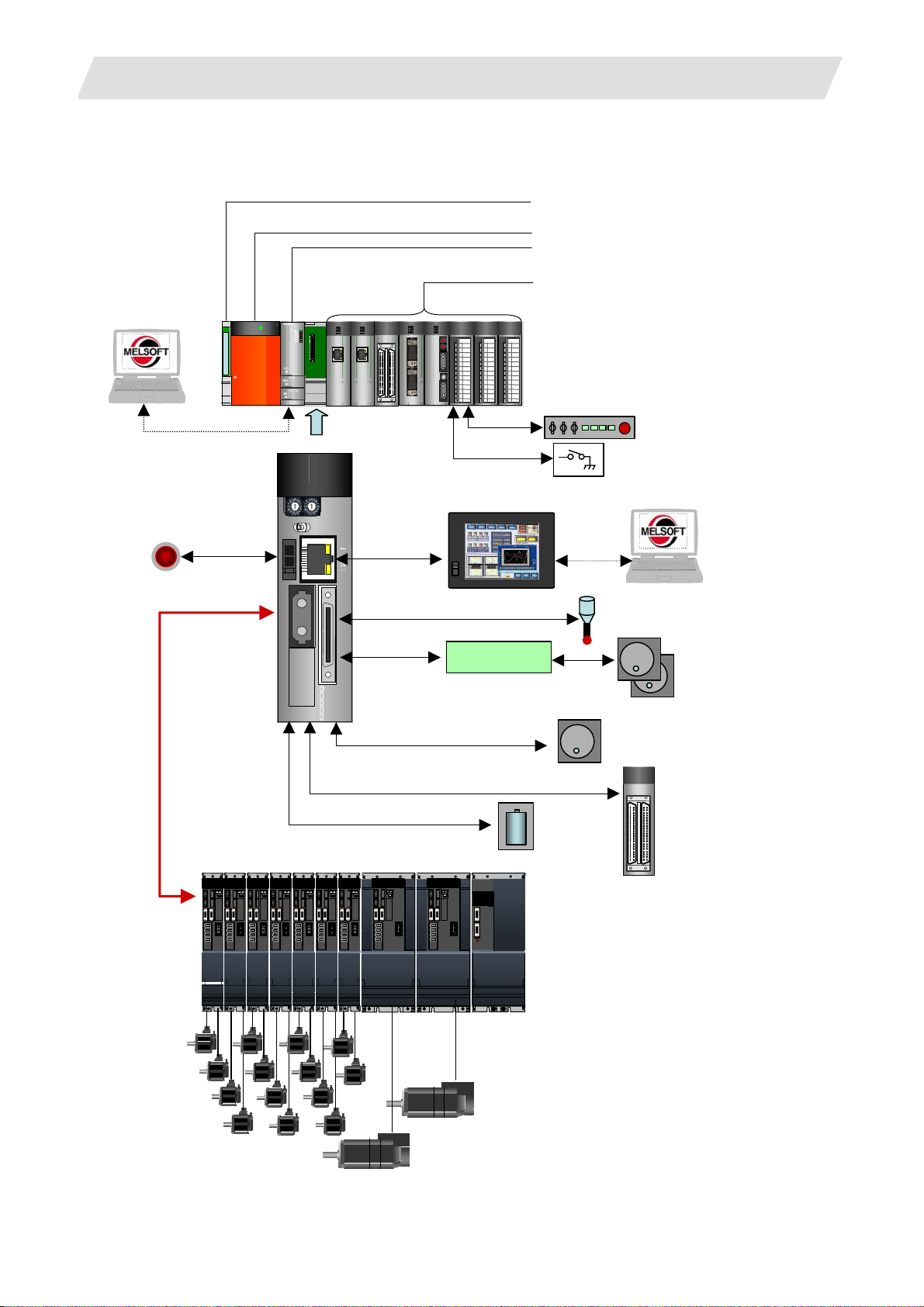
1. System Configurations
1. System Configurations
QJ71E71-100
QJ71E71-100
QJ71E71-100
QJ71E71-100
QJ71E71-100
QJ71E71-100
QJ71E71-100
QJ71E71-100
RUN
RUN
RUN
RUN
RUN
RUN
RUN
RUN
INIT.
INIT.
INIT.
INIT.
INIT.
INIT.
INIT.
INIT.
OPEN
OPEN
OPEN
OPEN
OPEN
OPEN
OPEN
OPEN
SD
SD
SD
SD
SD
SD
SD
SD
USB / Serial
Emergency Stop
MELSEC
MELSEC
MELSEC
MELSEC
PULL
PULL
PULL
PULL
MITSUBISHI
MITSUBISHI
MITSUBISHI
MITSUBISHI
POWER
POWER
POWER
POWER
Q173NCCPU
Q173NCCPU
MELSEC Basic Base
MELSEC Power supply
MELSEC PLC CPU module Universal model
MELSEC I/O module, MELSEC Network module
QXxxxxQXxxxx
QXxxxxQXxxxx QXxxxxQXxxxx
QXxxxxQXxxxx
QJ71E71-100
QJ71E71-100
QJ71E71-100
QJ71E71-100
QJ71E71-100
QJ71E71-100
QJ71E71-100
QJ71E71-100
RUN
RUN
RUN
RUN
RUN
RUN
RUN
RUN
ERR.
ERR.
ERR.
ERR.
ERR.
ERR.
ERR.
ERR.
ERR.
ERR.
ERR.
ERR.
ERR.
ERR.
ERR.
ERR.
INIT.
INIT.
INIT.
INIT.
INIT.
INIT.
INIT.
INIT.
COM.ERR.
COM.ERR.
COM.ERR.
COM.ERR.
COM.ERR.
COM.ERR.
COM.ERR.
COM.ERR.
COM.ERR.
COM.ERR.
COM.ERR.
COM.ERR.
COM.ERR.
COM.ERR.
COM.ERR.
COM.ERR.
OPEN
OPEN
OPEN
OPEN
OPEN
OPEN
OPEN
OPEN
100M RD
100M RD
100M RD
100M RD
100MRD
100MRD
100MRD
100MRD
100M RD
100M RD
100M RD
100M RD
100MRD
100MRD
100MRD
100MRD
SD
SD
SD
SD
SD
SD
SD
SD
QJ71E71-100QJ71E71-100QJ71E71-100QJ71E71-100
QJ71E71-100QJ71E71-100QJ71E71-100QJ71E71-100
QJ71E71-100QJ71E71-100QJ71E71-100QJ71E71-100
QJ71E71-100QJ71E71-100QJ71E71-100QJ71E71-100
QJ71E71-100QJ71E71-100QJ71E71-100QJ71E71-100
QJ71E71-100QJ71E71-100QJ71E71-100QJ71E71-100
QJ71E71-100QJ71E71-100QJ71E71-100QJ71E71-100
QJ71E71-100QJ71E71-100QJ71E71-100QJ71E71-100
ERR.
ERR.
ERR.
ERR.
ERR.
ERR.
ERR.
ERR.
ERR.
ERR.
ERR.
ERR.
ERR.
ERR.
ERR.
ERR.
RUN
RUN
RUN
RUN
RUN
RUN
RUN
RUN
RUN
RUN
RUN
RUN
RUN
RUN
RUN
RUN
COM.ERR.
COM.ERR.
COM.ERR.
COM.ERR.
COM.ERR.
COM.ERR.
COM.ERR.
COM.ERR.
COM.ERR.
COM.ERR.
COM.ERR.
COM.ERR.
COM.ERR.
COM.ERR.
COM.ERR.
COM.ERR.
INIT.
INIT.
INIT.
INIT.
INIT.
INIT.
INIT.
INIT.
INIT.
INIT.
INIT.
INIT.
INIT.
INIT.
INIT.
INIT.
OPEN
OPEN
OPEN
OPEN
OPEN
OPEN
OPEN
OPEN
OPEN
OPEN
OPEN
OPEN
OPEN
OPEN
OPEN
OPEN
100MRD
100MRD
100MRD
100MRD
100MRD
100MRD
100MRD
100MRD
100MRD
100MRD
100MRD
100MRD
100MRD
100MRD
100MRD
100MRD
SD
SD
SD
SD
SD
SD
SD
SD
SD
SD
SD
SD
SD
SD
SD
SD
QXxxxxQXxxxx QXxxxxQXxxxx
ERR.
ERR.
ERR.
ERR.
ERR.
ERR.
ERR.
ERR.
ERR.
ERR.
ERR.
ERR.
ERR.
ERR.
ERR.
ERR.
RUN
RUN
RUN
RUN
RUN
RUN
RUN
RUN
RUN
RUN
RUN
RUN
RUN
RUN
RUN
RUN
COM.ERR.
COM.ERR.
COM.ERR.
COM.ERR.
COM.ERR.
COM.ERR.
COM.ERR.
COM.ERR.
COM.ERR.
COM.ERR.
COM.ERR.
COM.ERR.
COM.ERR.
COM.ERR.
COM.ERR.
COM.ERR.
INIT.
INIT.
INIT.
INIT.
INIT.
INIT.
INIT.
INIT.
INIT.
INIT.
INIT.
INIT.
INIT.
INIT.
INIT.
INIT.
OPEN
OPEN
OPEN
OPEN
OPEN
OPEN
OPEN
OPEN
OPEN
OPEN
OPEN
OPEN
OPEN
OPEN
OPEN
OPEN
100M RD
100M RD
100M RD
100M RD
100M RD
100M RD
100M RD
100M RD
100M RD
100M RD
100M RD
100M RD
100M RD
100M RD
100M RD
100M RD
SD
SD
SD
SD
SD
SD
SD
SD
SD
SD
SD
SD
SD
SD
SD
SD
Operation panel
Switch
GOT1000 (SVGA / XVGA)
FRONT
FRONT
BATBAT
MPG
MPG
ACFAILACFAIL
RIO
RIO
Servo / Spindle Drive Unit
MITSUBISHI MITSUBISHI MITSUBISHI MITSUBISHI MITSUBISHI MITSUBISHI MITSUBISHI
USB
SKIP
(Sensor)
Signal spliter
FCU7-EX387
4 channel
Manual PLG #2
Manual PLG #3
Manual PLG #1
Battery
Safety I/O
module
(in Base)
MITSUBISHI
MITSUBISHI
MITSUBISHI
I - 1
Page 20
2. General Specifications
2. General Specifications
General specifications of NC CPU are shown below.
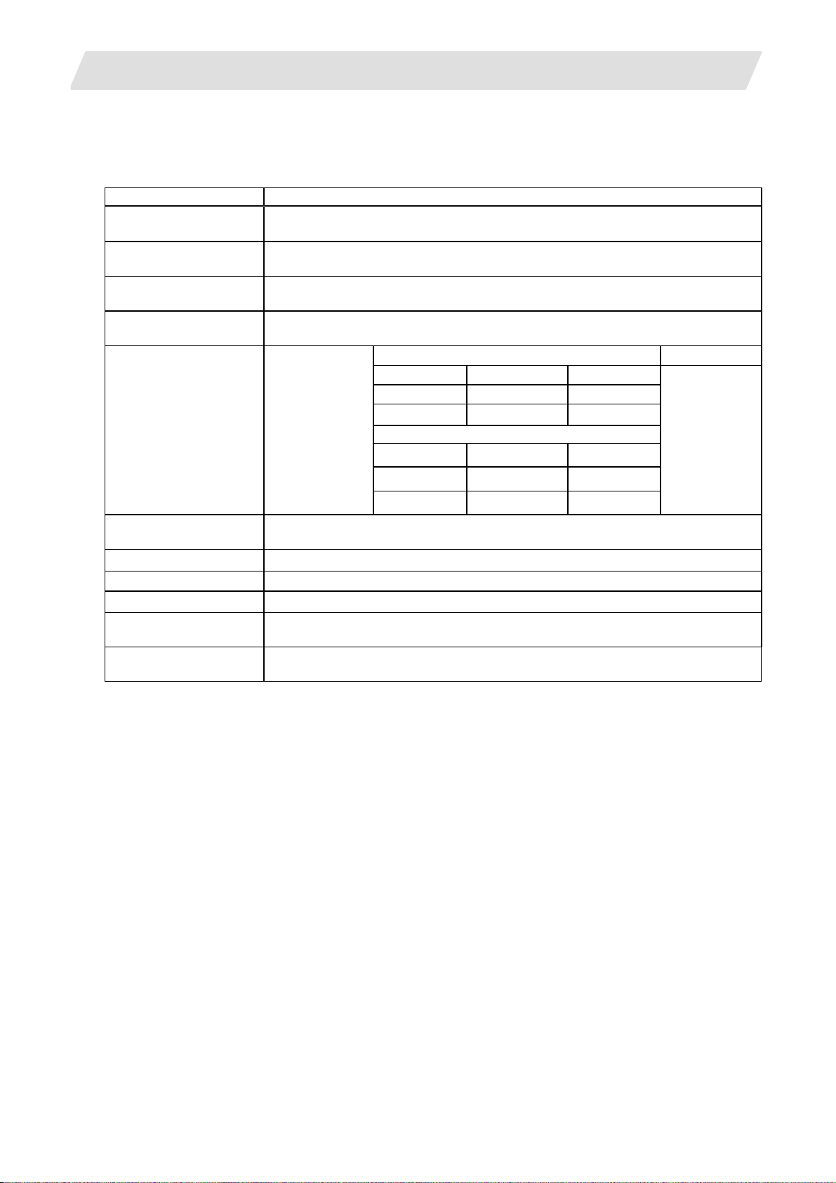
Item Specifications
Working ambient
temperature
Storage ambient
temperature
Working ambient
humidity
Storage ambient
humidity
Vibration resistance
Conforming to
JIS B 3502
IEC61131-2
Impact resistance
(147m/s
Working atmosphere
Altitude
Installing
Overvoltage
Category (Note 1)
Pollution Class
(Note 2)
(Note 1) This indicates the section of the power supply to which the equipment is assumed to be
connected between the public electrical power distribution network and the machinery
within premises. Category II applies to equipment for which electrical power is supplied
from fixed facilities.
The surge voltage withstand level for up to the rated voltage of 300 V is 2500V.
(Note 2) This index indicates the degree to which conductive material is generated in terms of the
environment in which the equipment is used.
In the environment corresponding to "Pollution level 2", basically only nonconductive
pollution occurs, however temporary conductivity may occur due to the occasional
condensing.
0 to 55°C
-25 to 75°C (-20 to 60°C for M700 series)
5 to 95% RH (with no dew condensation)
5 to 95% RH (with no dew condensation)
Under intermittent vibration
Sweep count
Frequency Acceleration Amplitude
10 to 57Hz - 0.075mm
57 to150Hz 9.8m/s2 -
When there is a continuous vibration
Frequency Acceleration Amplitude
each in X, Y,
Z directions
(for 80 min.)
10 to 57Hz - 0.035mm
2
57 to150Hz 4.9 m/s
Conforming to JIS B 3502, IEC61131-2
2
[15.0G], 3 times in each of 3 directions X, Y, Z)
-
No corrosive gases
2000m or less
Inside control panel
II or less
2 or less
10 times
I - 2
Page 21
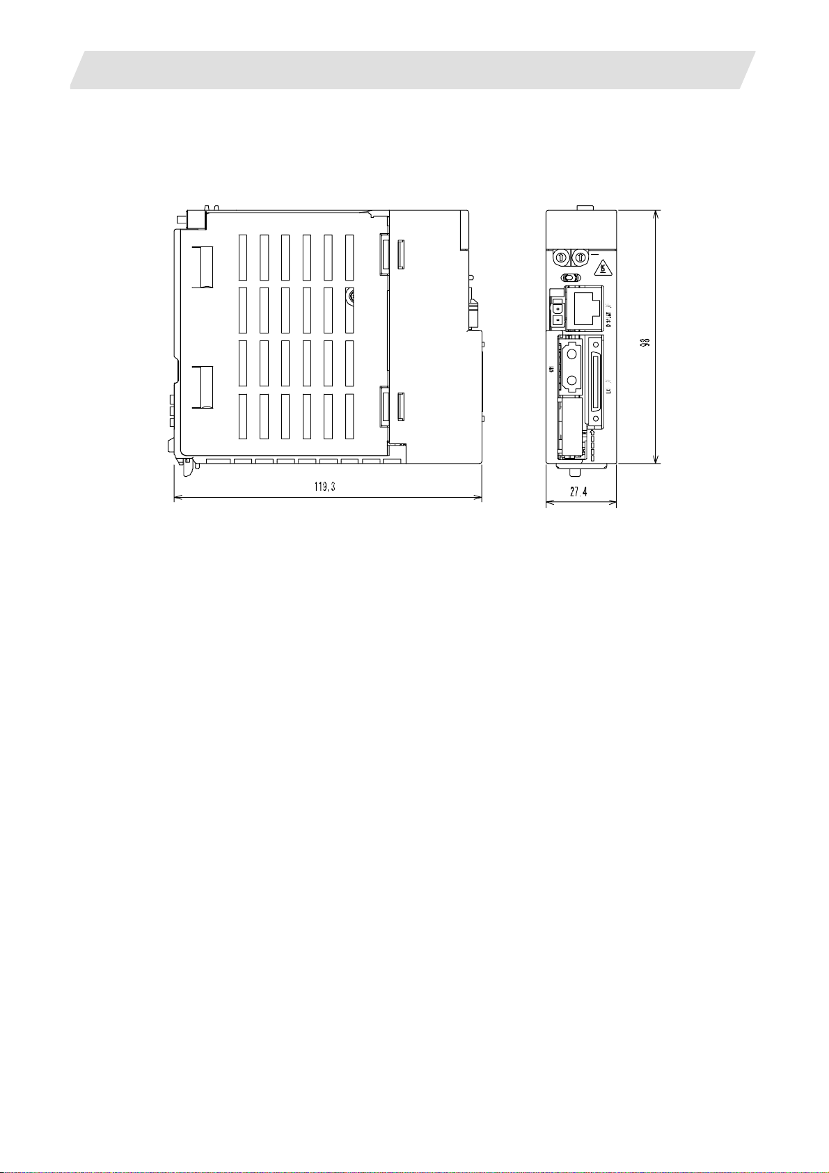
3. Outline Drawing
3. Outline Drawing
3.1 NC CPU Model Q173NCCPU
3.1 NC CPU Model Q173NCCPU
Q173 NCCPU
SW
SW
2
11
2
R
CAUTION
CAUTION
EMG
FRONT
FRONT
BATBAT
MPG
MPG
ACFAILLACFAIL
RIO
RIO
I - 3
Page 22

4. Servo/Spindle Drive System
4. Servo/Spindle Drive System
(1) Power supply regenerative type
200VAC (50Hz)/200 to 230VAC (60Hz)
MDS-D-V1 1st axis servo drive unit
MDS-D-V2 2nd axis servo drive unit
MDS-D-SP Spindle drive unit
MDS-D-CV Power supply unit
(2) Resistance regenerative type
200VAC (50Hz)/200 to 230VAC (60Hz)
MDS-D-SVJ3 1st axis servo drive unit
MDS-D-SPJ3 Spindle drive unit
MDS-D-V1/V2 Series MDS-DH-V1/V2 Series
+10% -15%
MDS-D-SVJ3/SPJ3 Series
+10% -15%
380 to 440VAC (50Hz)/380 to 480VAC (60Hz)
±10%
MDS-DH-V1 1st axis servo drive unit
MDS-DH-V2 2nd axis servo drive unit
MDS-DH-SP Spindle drive unit
MDS-DH-CV Power supply unit
I - 4
Page 23

5. CNC Signals (PLC Interface Signals)
5. CNC Signals (PLC Interface Signals)
The CNC signal includes the following signals.
Refer to "PLC Interface Manual" for detail.
Bit Type Input Signals
(CNC->PLC)
System State
24 hours continuous operation
Safety signal unconfirmed after
compare error
Controller ready completion
Servo ready completion
Door open enable
In spindle synchronization
Spindle rotation speed
synchronization completion
Spindle phase synchronization
completion
Chuck close confirmation
Battery warning
Battery alarm
NC alarm 1
NC alarm 2 (Servo alarm)
In door interlock
Axis State
Servo ready
Axis selection
In axis plus motion
In axis minus motion
1st reference position reached
2nd reference position reached
3rd reference position reached
4th reference position reached
Near reference position
NC axis up-to-speed
Zero point initialization set
completed
Zero point initialization set error
completed
In zero point initialization
Zero point initialization incomplete
Current limit reached
Unclamp command
In-position
Part System State
In jog mode
In handle mode
In incremental mode
In manual arbitrary feed mode
In reference position return mode
In automatic initial set mode
In program operation mode (In
memory mode)
In MDI mode
In automatic operation "run"
In automatic operation "start"
In automatic operation "pause"
In "reset"
In manual arbitrary feed
In rewind
Motion command completion
All axes in-position
All axes smoothing zero
Manual arbitrary feed completion
External search finished
In rapid traverse
In cutting feed
In tapping
In thread cutting
In synchronous feed
In constant surface speed
In skip
In reference position return
F 1-digit commanded
In tool life management output
Tool life over
NC alarm 3 (Program error)
NC alarm 4 (Operation error)
Search & start (error)
Search & start (search)
Illegal axis selected
F 1-digit No. code 1
F 1-digit No. code 2
F 1-digit No. code 4
M code independent output M00
M code independent output M01
M code independent output M02
M code independent output M30
M function strobe 1
M function strobe 2
M function strobe 3
M function strobe 4
Manual numerical command
Tool change position return
completion
New tool change
T function strobe 1
T function strobe 2
T function strobe 3
T function strobe 4
2nd M function strobe 1
2nd M function strobe 2
2nd M function strobe 3
2nd M function strobe 4
S function strobe 1
S function strobe 2
S function strobe 3
S function strobe 4
S function strobe 5
S function strobe 6
S function strobe 7
Position switch 1
Position switch 2
Position switch 3
Position switch 4
Position switch 5
Position switch 6
Position switch 7
Position switch 8
Tap retract possible
No. of work machining over
Absolute position warning
Position switch 9
Position switch 10
Position switch 11
Position switch 12
Position switch 13
Position switch 14
Position switch 15
Position switch 16
Spindle State
S command gear No. illegal
S command max./min. command
value over
S command no gear selected
Spindle speed upper limit over
Spindle speed lower limit over
Spindle gear shift command 1
Spindle gear shift command 2
Current detection
Speed detection
In spindle alarm
Zero speed
Spindle up-to-speed
Spindle in-position
In L coil selection
Spindle ready-ON
Spindle servo-ON
In spindle forward run
In spindle reverse run
Z-phase passed
Position loop in-position
In torque limit
I - 5
Page 24

5. CNC Signals (PLC Interface Signals)
Data Type Input Signals
(CNC->PLC)
System State
Speed monitor door open
possible
CRT display information
Emergency stop cause
User macro output #1132
(Controller -> PLC)
User macro output #1133
(Controller -> PLC)
User macro output #1134
(Controller -> PLC)
User macro output #1135
(Controller -> PLC)
CNC software version code
Battery drop cause
Temperature warning cause
Spindle synchronization phase
error 1
Spindle synchronization phase
error 2
Spindle synchronization phase
error output
Spindle synchronization Phase
error monitor
Spindle synchronization Phase
error monitor (lower limit)
Spindle synchronization Phase
error monitor (upper limit)
Spindle synchronization Phase
offset data
Part System State
External search status
M code data 1
M code data 2
M code data 3
M code data 4
S code data 1
S code data 2
S code data 3
S code data 4
T code data 1
T code data 2
T code data 3
T code data 4
2nd M function data 1
2nd M function data 2
2nd M function data 3
2nd M function data 4
Tool No.
Group in tool life management
No. of work machining(current
value)
Near reference position (per
reference position)
Tool life usage data
No. of work machining(maximum
value)
Error code output
S code data 5
S code data 6
S code data 7
User Macro output #1132
(Controller -> PLC)
User Macro output #1133
(Controller -> PLC)
User Macro output #1134
(Controller -> PLC)
User Macro output #1135
(Controller -> PLC)
Thermal expansion compensation
amount
Spindle command rotation speed
input
Spindle command final data
(Rotation speed)
Spindle actual speed
Contactor shutoff test signal
Integration time input 1
Integration time input 2
Data protect key 1
Data protect key 2
Data protect key 3
CRT changeover completion
Display changeover $1
Display changeover $2
PLC emergency stop
Door open I
Door open II
PLC axis control buffering mode
valid
PLC axis 1st handle valid
PLC axis 2st handle valid
PLC axis 3st handle valid
Spindle synchronization cancel
Chuck close
Spindle synchronization
Spindle phase synchronization
Spindle synchronous rotation
direction
Phase shift calculation request
Phase offset request
Error temporary cancel
Axis State
Spindle State
Bit Type Output Signals
(PLC->CNC)
System Command
PLC axis near point detection 1
PLC axis near point detection 2
PLC axis near point detection 3
PLC axis near point detection 4
PLC axis near point detection 5
PLC axis near point detection 6
PLC axis near point detection 7
PLC axis control valid 1
PLC axis control valid 2
PLC axis control valid 3
PLC axis control valid 4
PLC axis control valid 5
PLC axis control valid 6
PLC axis control valid 7
Axis Command
Control axis detach
Servo OFF
Mirror image
External deceleration +
External deceleration Automatic interlock +
Automatic interlock Manual interlock +
Manual interlock Automatic machine lock
Manual machine lock
Feed axis selection +
Feed axis selection Manual/Automatic simultaneous
valid
Control axis detach 2
Current limit changeover
Droop release request
Zero point initialization set mode
Zero point initialization set start
Unclamp completion
Part System Command
Jog mode
Handle mode
Incremental mode
Manual arbitrary feed mode
Reference position return mode
Automatic initialization mode
Program operation mode
(Memory mode)
MDI mode
Automatic operation "start"
command (Cycle start)
Automatic operation "pause"
command (Feed hold)
Single block
Block start interlock
Cutting block start interlock
Dry run
Error detect
NC reset 1
I - 6
Page 25

5. CNC Signals (PLC Interface Signals)
NC reset 2
Reset & rewind
Chamfering
Automatic restart
External search strobe
M function finish 1
M function finish 2
Tool length measurement 1
Tool length measurement 2 (L
system)
Synchronization correction mode
Macro interrupt
Rapid traverse
Manual absolute
Recalculation request
Optional block skip 1
Reference position selection code
1
Reference position selection code
2
Reference position selection
method
Optional block skip 2
Optional block skip 3
Optional block skip 4
Optional block skip 5
Optional block skip 6
Optional block skip 7
Optional block skip 8
Optional block skip 9
1st handle axis selection code 1
1st handle axis selection code 2
1st handle axis selection code 4
1st handle axis selection code 8
1st handle axis selection code 16
1st handle valid
2nd handle axis selection code 1
2nd handle axis selection code 2
2nd handle axis selection code 4
2nd handle axis selection code 8
2nd handle axis selection code 16
2nd handle valid
3rd handle axis selection code 1
3rd handle axis selection code 2
3rd handle axis selection code 4
3rd handle axis selection code 8
3rd handle axis selection code 16
3rd handle valid
Override cancel
Manual override method selection
Miscellaneous function lock
Tap retract
Reference position retract
Cutting feedrate override code 1
Cutting feedrate override code 2
Cutting feedrate override code 4
Cutting feedrate override code 8
Cutting feedrate override code 16
2nd cutting feedrate override valid
Cutting feedrate override method
selection
Rapid traverse override code 1
Rapid traverse override code 2
Rapid traverse override method
selection
Manual feedrate code 1
Manual feedrate code 2
Manual feedrate code 4
Manual feedrate code 8
Manual feedrate code 16
Manual feedrate method selection
Feedrate least increment code 1
Feedrate least increment code 2
Jog synchronous feed valid
Jog handle synchronous
Current limit mode 1
Current limit mode 2
Handle/incremental feed
multiplication code 1
Handle/incremental feed
multiplication code 2
Handle/incremental feed
multiplication code 4
Handle/incremental feed
magnification method selection
Tool alarm 1 (M system)/Tool skip
1 (L system)
Tool alarm 2 (M system)
Usage data count valid
Tool life management input (M
system)
Tool change reset
Manual arbitrary feed 1st axis
selection code 1
Manual arbitrary feed 1st axis
selection code 2
Manual arbitrary feed 1st axis
selection code 4
Manual arbitrary feed 1st axis
selection code 8
Manual arbitrary feed 1st axis
selection code 16
Manual arbitrary feed 1st axis
valid
Manual arbitrary feed 2nd axis
selection code 1
Manual arbitrary feed 2nd axis
selection code 2
Manual arbitrary feed 2nd axis
selection code 4
Manual arbitrary feed 2nd axis
selection code 8
Manual arbitrary feed 2nd axis
selection code 16
Manual arbitrary feed 2nd axis
valid
Manual arbitrary feed 3rd axis
selection code 1
Manual arbitrary feed 3rd axis
selection code 2
Manual arbitrary feed 3rd axis
selection code 4
Manual arbitrary feed 3rd axis
selection code 8
Manual arbitrary feed 3rd axis
selection code 16
Manual arbitrary feed 3rd axis
valid
Manual arbitrary feed smoothing
off
Manual arbitrary feed axis
independent
Manual arbitrary feed
EX.F/MODAL.F
Manual arbitrary feed G0/G1
Manual arbitrary feed MC/WK
Manual arbitrary feed ABS/INC
Manual arbitrary feed stop
Manual arbitrary feed strobe
2nd reference position return
interlock
Search & start
Spindle Command
Gear shift completion
Spindle override code 1
Spindle override code 2
Spindle override code 4
Spindle override method selection
Spindle gear selection code 1
Spindle gear selection code 2
Spindle stop
Spindle gear shift
Spindle orientation
Spindle forward run start
Spindle reverse run start
Spindle forward run index
Spindle reverse run index
Spindle orientation command
L coil selection
Torque limit 1
Torque limit 2
Torque limit 3
Data Type Output Signals
(PLC->CNC)
System Command
Speed monitor mode
User macro input #1032
(PLC -> Controller)
User macro input #1033
(PLC -> Controller)
User macro input #1034
I - 7
Page 26

5. CNC Signals (PLC Interface Signals)
(PLC -> Controller)
User macro input #1035
(PLC -> Controller)
PLC version code
1st axis index
2nd axis index
3rd axis index
4th axis index
5th axis index
6th axis index
7th axis index
8th axis index
9th axis index
10th axis index
11th axis index
12th axis index
13th axis index
14th axis index
15th axis index
16th axis index
Spindle synchronization Basic
spindle selection
Spindle synchronization
Synchronous spindle selection
Spindle synchronization Phase
shift amount
PLC version code (method 2)
Part System Command
1st cutting feedrate override
2nd cutting feedrate override
Rapid traverse override
Manual feedrate
Handle/incremental feed
magnification
2nd handle feed magnification
3rd handle feed magnification
Manual arbitrary feed 1st axis
travel amount
Manual arbitrary feed 2nd axis
travel amount
Manual arbitrary feed 3rd axis
travel amount
OT ignored
Near-point dog ignored
Tool group No. designation
Synchronization control operation
method
Search & start program No.
Workpiece coordinate offset
measurement compensation No.
Selected tool No.
External search device No.
External search program No.
External search sequence No.
External search block No.
User Macro input #1032
(PLC -> Controller)
User Macro input #1033
(PLC -> Controller)
User Macro input #1034
(PLC -> Controller)
User Macro input #1035
(PLC -> Controller)
External machine coordinate
system compensation data
Each axis reference position
selection
Thermal expansion offset
compensation amount
Thermal expansion max.
compensation amount
Spindle command rotation speed
output
S command override
Multi-point orientation position
data
PLC axis state
PLC axis control
Window result information
Window command
Data registered to magazine for M
system
Tool life management (M system)
Safety observing
Axis State
Spindle Command
Classified Under Purpose
(CNC->PLC)
(PLC->CNC)
I - 8
Page 27

II. FUNCTIONAL SPECIFICATIONS
Page 28

Page 29

1. Control Axes
1.1 Control Axes
1. Control Axes
The NC axis, spindle, PLC axis are generically called the control axis.
The NC axis is an axis that can be manually operated, or automatically operated with the machining program.
The PLC axis is an axis that can be controlled from the PLC ladder.
1.1 Control Axes
1.1.1 Number of Basic Control Axes (NC axes)
M system : { 3 axes L system : { 3 axes
1.1.2 Max. Number of Control Axes (NC axes + Spindles + PLC axes)
A number of axes that are within the maximum number of control axes, and that does not exceed the
maximum number given for the NC axis, spindle and PLC axis can be used.
For example, if 16 NC axes are used, this alone is the maximum number of control axes, so a spindle and
PLC axis cannot be connected.
Max. number of control axes (NC axes + spindles + PLC axes)
M system : 16 axes L system : 16 axes
Max. number of NC axes (in total for all the part systems)
M system : 16 axes L system : 16 axes
Max. number of spindles
M system : 7 axes L system : 4 axes
Max. number of PLC axes
M system : 7 axes L system : 7 axes
1.1.4 Number of Simultaneous Contouring Control Axes
Simultaneous control of up to four axes or less is possible in the same part system.
However, for actual use, the machine tool builder specification will apply.
M system : 4 axes L system : 4 axes
1.1.5 Max. Number of NC Axes in a Part System
M system : 8 axes L system : 8 axes
II
- 1
Page 30

1. Control Axes
1.2 Control Part System
1.2.1 Standard Number of Part Systems
M system : 1 part system L system : 1 part system
1.2.2 Max. Number of Part Systems
M system : Δ7 part systems L system : Δ3 part systems
For actual use, the machine tool builder specification will apply.
1.3 Control Axes and Operation Modes
1.3.2 Memory Mode
M system : { L system : {
The machining programs stored in the memory of the NC unit are run.
1.3.3 MDI Mode
1.2 Control Part System
M system : { L system : {
The MDI data stored in the memory of the NC unit is executed. Once executed, the MDI data is set to the
"setting incomplete" status, and the data will not be executed unless the "setting completed" status is
established by performing screen operations.
II
- 2
Page 31

2. Input Command
2.1 Data Increment
2. Input Command
2.1 Data Increment
Least command increment: 1 μm (Least input increment: 1 μm)
M system : { L system : {
Least command increment: 0.1 μm (Least input increment: 0.1 μm)
M system : Δ L system : Δ
The data increment handled in the controller include the least input increment, least command increment
and least detection increment. Each type is set with parameters.
(1) The least input increment indicates the increment handled in the internal processing of the controller.
The counter and tool offset data, etc., input from the screen is handled with this increment. This
increment is applied per part system (all part systems, PLC axis).
Input
Increment type
increment
(parameter)
Least input increment
B 0.001 0.001 0.0001 0.001
C 0.0001 0.0001 0.00001 0.0001
(Note 1) The inch and metric systems cannot be used together.
(2) The command increment indicates the command increment of the movement command in the
machining program. This can be set per axis.
Command
Increment type
increment
(parameter)
10 0.001 0.001 0.0001 0.001
Command increment
100 0.01 0.01 0.001 0.01
1000 0.1 0.1 0.01 0.1
10000 1.0 1.0 0.1 1.0
(Note 1) The inch and metric systems cannot be used together.
(3) The least detection increment indicates the detection increment of the NC axis and PLC axis detectors.
The increment is determined by the detector being used.
Metric unit system Inch unit system
Linear axis
(Unit = mm)
Rotary axis
(Unit = °)
Linear axis
(Unit = inch)
Metric unit system Inch unit system
Linear axis
(Unit = mm)
Rotary axis
(Unit = °)
Linear axis
(Unit = inch)
Rotary axis
(Unit = °)
Rotary axis
(Unit = °)
II
- 3
Page 32

2. Input Command
2.2 Unit System
2.2 Unit System
2.2.1 Inch/Metric Changeover
M system : Δ L system : Δ
The unit systems of the data handled in the controller include the metric unit system and inch unit system.
The type can be designated with the parameters and machining program. The unit system can be set
independently for the (1) Program command, (2) Setting data such as offset amount and (3) Parameters.
Unit system Length data Meaning
Metric unit system 1.0 1.0 mm
Inch unit system 1.0 1.0 inch
(Note 1) For the angle data, 1.0 means 1 degree (°) regardless of the unit system.
Data
Parameter
0
I_inch
1
M_inch
(Note 1) The parameter changeover is valid after the power is turned ON again.
(Note 2) Even if parameter "I_inch" is changed, the screen data (offset amount, etc.) will not be
(Note 3) When the power is turned ON or resetting is performed, the status of the G20/G21 modal depends
0 Metric unit system
1
automatically converted.
on the "I_G20" parameter setting.
Machining program
G20 Inch unit system
G21 Metric unit system
G20 Inch unit system
G21 Metric unit system
Not affected Not affected
Screen data
(Offset amount, etc.)
Metric unit system
Inch unit system
Parameter
Not affected
Inch unit system
II
- 4
Page 33

2. Input Command
2.3 Program Format
2.3.1 Program Format
The G-code of L system is selected by parameter.
This specification manual explains the G function with G-code series 3 as standa rd.
2.3.1.1 Format 1 for Lathe (G code list 2, 3)
M system : - L system : {
2.3.1.2 Format 2 for Lathe (G code list 4, 5)
M system : - L system : {
2.3.1.4 Format 1 for Machining Center (G code list 1)
M system : { L system : -
2.3 Program Format
II
- 5
Page 34

2. Input Command
2.4 Command Value
2.4 Command Value
2.4.1 Decimal Point Input I, II
M system : { L system : {
There are two types of the decimal point input commands and they can be selected by parameter.
(1) Decimal point input type I (When parameter #1078 Decpt2 is 0.)
When axis coordinates and other data are supplied in machining program commands, the assignment
of the program data can be simplified by using the decimal point input. The minimum digit of a
command not using a decimal point is the same as the least command increment.
Usable addresses can be applied not only to axis coordinate values but also to spee d commands and
dwell commands.
The decimal point position serves as the millimeter unit in the metric mode, as the inch unit in the inch
mode and as the second unit in a time designation of dwell command.
(2) Decimal point input type II (When parameter #1078 Decpt2 is 1.)
As opposed to type I, when there is no decimal point, the final digit serves as the millimeter unit in the
metric mode, as the inch unit in the inch mode and as the second unit in the time designation.
The "." (point) must be added when commands below the decimal point are required.
Unit interpretation (for metric system)
Type I Type II
G00 X100. Y-200.5 X100mm, Y-200.5mm
G1 X100 F20. X100µm, F20mm/min X100mm, F20mm/min
G1 Y200 F100
G4 X1.5 Dwell 1.5 s
G4 X2 2ms 2s
(Note 1) The F unit is mm/min for either type (inch system : inch/min).
(Note 1)
Y200µm, F100mm/min Y200mm, F100mm/min
←
←
II
- 6
Page 35

2. Input Command
2.4 Command Value
2.4.2 Absolute/Incremental Command
M system : { L system : {
(1) M system
When axis coordinate data is issued in a machining program command, either the incremental
command method (G91) that commands a relative distance from the current position or the absolute
command method (G90) that moves to a designated position in a predetermined coordinate system can
be selected.
The absolute and incremental commands can be both used in one block, and ar e switched with G90 or
G91. However, the arc radius designation (R) and arc center designation (I, J, K) always use
incremental designations.
G90 ... Absolute command (absolute value command)
G91 ... Incremental command (incremental value command)
These G codes can be commanded multiple times in one block.
Example
Absolute value Incremental value Absolute value
(Note 1) As with the memory command, if there is no G90/G91 designation in the MDI command, the
(Incremental value command) (Absolute value command)
G 91 X 100. Y100. ;
G90 X100. G91 Y200. G90 Z300. ;
previously executed modal will be followed.
G 90 X 100. Y100. ;
End
point
Y100.
Current position
(0, 0)
X 100.
X 100.
Y100.
Y100.
Current position
Program coordinate
(0, 0)
End point
X100.
II
- 7
Page 36

2. Input Command
2.4 Command Value
(2) L system
When axis coordinate data is issued in a machining program command, either the incremental
command method that commands a relative distance from the current position or the absolute
command method that moves to a designated position in a predetermined coordinate syste m can be
selected.
When issuing an incremental value command, the axis address to be commanded as the incremental
axis name is registered in the parameter. However, the arc radius designation (R) and arc center
designation (I, J, K) always use incremental designations.
Absolute command (absolute value command) ... X, Z
Incremental command (incremental value command) ... U, W
Example G00 X100. W200. ;
Absolute value Incremental value
(Incremental value command)
G 00 U – u1 W – w1 ;
X X
Current position
(Absolute value c ommand)
G 00 X x1 Z z1 ;
Current position
End point
u1
2
x1
Z
End point
w1
z1
Z
(0,0)
The above drawing shows the case
for the diameter command.
(Note 1) In addition to the above command method using the above axis addresses, the absolute value
command and incremental value command can be switched by commanding the G code
(G90/G91). (Select with the parameters.)
The above drawing shows the case
for the diameter command.
II
- 8
Page 37

2. Input Command
r2r
2.4 Command Value
2.4.3 Diameter/Radius Designation
M system : - L system : {
For axis command value, the radius designation or diameter designation can be chan ged over with
parameters.
When the diameter designation is selected, the scale of the length of the selected axis is doubled. (Only the
half (1/2) of the commanded amount moves.)
This function is used when programming the workpiece dimensions on a lathe as diameters. Changing over
from the diameter designation to the radius designation or vice versa can be set separately for each axis.
X axis
P1
Spindle
When the tool is to be moved from point P1 to point P2
X command U command Remarks
Radius Diameter Radius Diameter
X = r1 X = 2r1 U = r2 U = 2r2
Radius and diameter commands
P2
1
Workpiece coordinate zero point
Even when a diameter command
has been selected, only the U
command can be made a radius
command by parameter.
Z axis
II
- 9
Page 38

3. Positioning/Interpolation
y
3.1 Positioning
3. Positioning/Interpolation
3.1 Positioning
3.1.1 Positioning
M system : { L system : {
This function carries out positioning at high speed using rapid traverse with the movement command value
given in the program.
G00 Xx1 Yy1 Zz1 ; (Also possible for additional axes A, B, C, U, V, W simultaneously)
x1, y1, z1: numerical values denoting the position data
The above command positions the tool by rapid traverse. The tool path takes the shortest distance to the
end point in the form of a straight line.
For details on the rapid traverse feed rate of the NC, refer to the section entitled "Rapid Traverse Rate".
Since the actual rapid traverse feed rate depends on the machine, refer to the specifications of the machine
concerned.
(1) The rapid traverse feed rate for each axis can be set independently with parameters.
(2) The number of axes which can be driven simultaneously depends on the specifications (number of
simultaneously controlled axes). The axes can be used in any combination within this range.
(3) The feed rate is controlled within the range that it does not exceed the rapid traverse rate of each axis
and so that the shortest time is taken. (Linear type)
Parameter setting enables movement at the rapid traverse rates of the respective axes independently
for each axis. In this case, the tool path does not take the form of a straight line to the end point. (NonLinear type)
(
(Example) Linear type (Moves linear
to the end point.)
G 00 G 91 X 100. Y 100. ;
Example)
G 00 G 91 X 100. Y 100. ;
Non-linear type (Each axis moves at
each parameter speed.)
100.
End point
100.
Y
End point
100.
Current position
X
100.
X
Y
Current position
(Note 1) If the acceleration/deceleration conditions differ between the axes, the path will not be linear to the
end point even when using the linear type.
(4) The tool is always accelerated at the start of the program command block and decelerated a t the end of
the block.
II
- 10
Page 39

3. Positioning/Interpolation
3.1 Positioning
3.1.2 Unidirectional Positioning
M system : { L system : -
The G60 command always moves the tool to the final position in a direction determined with parameters.
The tool can be positioned without backlash.
G60 Xx1 Yy1 Zz1 ; (Also possible for additional axes A, B, C, U, V, W simultaneously)
x1, y1, z1: numerical values denoting the position data
With the above command, the tool is first moved to a position distanced from the end point position by an
amount equivalent to the creep distance (parameter setting) and then moved to its final position.
For details on the rapid traverse feed rate of the NC, refer to the section entitled "Rapid Traverse Rate".
Since the actual rapid traverse feed rate depends on the machine, refer to the specifications of the machi ne
concerned.
Positioning to the final point is shown below (when this positioning is in the "+" direction.)
– +
(Example)
G60 G91 X100. Y100. ;
Interim point
End point
(1) The rapid traverse rate for each axis is the
value set with parameters as the G00
speed.
(2) The vector speed to the interim point is the
value produced by combining the distance
Y100.
and respective speeds.
(3) The creep distance of the distance
between the interim and end points can be
Current position
X100.
set independently for each axis by
"parameters".
(Note 1) The processing of the above pattern will be followed even for the machine lock and Z-axis
command cancel.
(Note 2) On the creep distance, the tool is moved with rapid traverse.
(Note 3) G60 is valid even for positioning in drilling in the fixed cycle.
(Note 4) When the mirror image function is on, the tool will be moved in the reverse direction by mirror
image as far as the interim position, but operation over the creep distance with the final advance
will not be affected by the mirror image.
II
- 11
Page 40

3. Positioning/Interpolation
3.2 Linear/Circular Interpolation
3.2 Linear/Circular Interpolation
3.2.1 Linear Interpolation
M system : { L system : {
Linear interpolation is a function that moves a tool linearly by the movement command value supplied in the
program at the cutting feed rate designated by the F code.
G01 Xx1 Yy1 Zz1 Ff1 ; (Also possible for additional axes A, B, C, U, V, W
simultaneously)
x1, y1, z1
f1
Linear interpolation is executed by the above command at the f1 feed rate. The tool path takes the shortest
distance to the end point in the form of a straight line.
For details on the f1 command values for NC, refer to the section entitled "Cutting Feed Rate". Since the
actual cutting feed rate depends on the machine, refer to the specifications of the machine conce rn ed.
(Example
)
G01 G91 X100. Y100. F120 ;
Y
Feed rate
(120mm/min)
: numerical values denoting the position data
: numerical value denoting the feed rate data
(1) The cutting feed rate command
End point
100.
(85mm/min)
(2) The component speeds of each
moves the tool in the vector
direction.
axis are determined by the
proportion of respective
command values to the actual
movement distance with linear
interpolation.
Current
position
100. (85mm/min)
X
(1) The number of axes which can be driven simultaneously depends on the specifications (number of
simultaneously controlled axes). The axes can be used in any combination within this range.
(2) The feed rate is controlled so that it does not exceed the cutting feed rate clamp of each axis.
(3) When a rotary axis has been commanded in the same block, it is treated as a linear axis in degree(°)
units (1° = 1mm), and linear interpolation is performed.
II
- 12
Page 41

3. Positioning/Interpolation
Y
X
X
3.2 Linear/Circular Interpolation
3.2.2 Circular Interpolation (Center/Radius Designation)
M system : { L system : {
(1) Circular interpolation with I, J, K commands
This function moves a tool along a circular arc on the plane selected by the plane selection G code with
movement command value supplied in the program.
G02(G03) Xx1 Yy1 Ii1 Jj1 Ff1 ; (Also possible for additional axes A, B, C, U, V, W)
G02, G03 : Arc rotation direction
Xx1, Yy1 : End point coordinate values
Ii1, Jj1 : Arc center coordinate values
Ff1 : Feed rate
The above commands move the tool along the circular arc at the f1 feed rate. The tool moves along a
circular path, whose center is the position from the start point designated by distance "i1" in the X-axis
direction and distance "j1" in the Y-axis direction, toward the end point.
The direction of the arc rotation is specified by
G02 or G03.
G02: Clockwise (CW)
G03: Counterclockwise (CCW)
The plane is selected by G17, G18 or G19.
G17: XY plane
G18: ZX plane
Y
G17
G02
G18
G02
G19: YZ plane
(Example)
commands.
See below for examples of circular
Start point
F
I, J
End point
G03
Z
G19
G02
G03
Y
G03
Z
Center
X
(a) The axes that can be commanded simultaneously are the two axes for the selected plane.
(b) The feed rate is controlled so that the tool always moves at a speed along the circumference of the
circle.
(c) Circular interpolation can be commanded within a range extendi ng from 0
to 360°.
°
(d) The max. value of the radius can be set up to six digits above the decimal point.
(Note 1) The arc plane is always based on the G17, G18 or G19 command. If a command is issued with
two addresses which do not match the plane, an alarm will occur.
(Note 2) The axes configuring a plane can be designated by parameters. Refer to the section entitled
"Plane Selection".
II
- 13
Page 42

3. Positioning/Interpolation
A
3.2 Linear/Circular Interpolation
(2) R-specified circular interpolation
Besides the designation of the arc center coordinates using the above-mentioned I, J and K commands,
arc commands can also be issued by designating the arc radius di rectly.
G02(G03) Xx1 Yy1 Rr1 Ff1 ; (Also possible for additional axes A, B, C, U, V, W )
G02, G03 : Arc rotation direction
Xx1, Yy1 : End point coordinate values
Rr1 : Arc radius
Ff1 : Feed rate
G02 or G03 is used to designate the direction of the arc rotation.
The arc plane is designated by G17, G18 or G19.
The arc center is on the bisector which orthogonally intersects the segment connecting the start and end
points, and the point of intersection with the circle, whose radius has been designated with the start point
serving as the center, is the center coordinate of the arc command.
When the sign of the value of R in the command program is positive, the command will be for an arc of 180
or less; when it is negative, it will be for an arc exceeding 180
(Example)
G02 G91 X100. Y100. R100. F120 ;
Y
.
°
°
rc end point coordinates
Feed rate:
120mm/min
Current position
(arc start point)
R100.
(X, Y)
X
(a) The axes that can be commanded simultaneously are the two axes for the selected plane.
(b) The feed rate is controlled so that the tool always moves at a speed along the circumference of the
circle.
(Note 1) The arc plane is always based on the G17, G18 or G19 command. If a command is issued with
two addresses which do not match the plane, an alarm will occur.
II
- 14
Page 43

3. Positioning/Interpolation
3.2 Linear/Circular Interpolation
3.2.3 Helical Interpolation
M system : Δ L system : -
With this function, any two of three axes intersecting orthogonally are made to perform circular interpolation
while the third axis performs linear interpolation in synchronization with the arc rotation. This simultaneous 3axis control can be exercised to machine large-diameter screws or 3-dimensional cams.
G17 G02(G03) Xx1 Yy1 Zz1 Ii1 Jj1 Pp1 Ff1 ;
G17 : Arc plane
G02, G03 : Arc rotation direction
Xx1, Yy1 : End point coordinate values for arc
Zz1 : End point coordinate value of linear axis
Ii1, Jj1 : Arc center coordinate values
Pp1 : Pitch No.
Ff1 : Feed rate
(1) The arc plane is designated by G17, G18 or G19.
(2) G02 or G03 is used to designate the direction of the arc rotation.
(3) Absolute or incremental values can be assigned for the arc end point coordin ate s and the end point
coordinate of the linear axis, but incremental values must be assigned for the arc center coordinate s.
(4) The linear interpolation axis is the other axis which is not included in the plane selection.
(5) Command the speed in the component direction that represents all the axes co mbined for the feed rate.
Pitch l1 is obtained by the formula below.
l1 = z1/((2
= θe - θs = arctan (ye/xe) - arctan (ys/xs)
θ
Where
xe, ye are the end point coordinates
The combination of the axes which can be commanded simultaneously depends on the spe cif ication s.
The axes can be used in any combination under the specifications. The feed rat e is controlled so that
the tool always moves at a speed along the circumference of the circle.
p1 + θ)/2π)
π •
xs, ys are the start point coordinates (0
≤ θ
< 2π)
II
- 15
Page 44

3. Positioning/Interpolation
(Example)
G91 G17 G02 X0. Y200. Z100. I–100. J100.
Start point
Z
End point
Command program path
Y
3.2 Linear/Circular Interpolation
Y
End
point
X
W
I-100
J100
Start point
X
XY plane projection path in command program
(Note 1) Helical shapes are machined by assigning linear commands for one axis which is not a circular
interpolation axis using an orthogonal coordinate system. It is also possible to assign the se
commands to two or more axes which are not circular interpolation axes.
When a simultaneous 4-axis command is used with
the V axis as the axis parallel to the Y axis, helical
interpolation will result for a cylinder which is
inclined as shown in the figure on the right. In other
words, linear interpolation of the Z and V axes is
carried out in synchronization with the circular
interpolation on the XY plane.
Z
•
V
End
point
•
X
Start point
Y
II
- 16
Page 45

4. Feed
4. Feed
4.1 Feed Rate
4.1.1 Rapid Traverse Rate (m/min)
M system : 1000 L system : 1000
[M system]
The rapid traverse rate can be set independently for each axis.
The rapid traverse rate is effective for G00, G27, G28, G29, G30 and G60 commands.
Override can be applied to the rapid traverse rate using the external signal supplied.
• Rapid Traverse Rate setting range
Least input increment B C
Metric input 1~1000000 (mm/min, °/min) 1~100000 (mm/min, °/min)
Inch input 1~39370 (inch/min) 1~3937 (inch/min)
Least input increment B : 0.001 mm (0.0001 inch)
Least input increment C : 0.0001 mm (0.00001 inch)
[L system]
The rapid traverse rate can be set independently for each axis.
The rapid traverse rate is effective for G00, G27, G28, G29, G30 and G53 commands.
Override can be applied to the rapid traverse rate using the external signal supplied.
• Rapid Traverse Rate setting range
Least input increment B C
Metric input 1~1000000 (mm/min, °/min) 1~100000 (mm/min, °/min)
Inch input 1~39370 (inch/min) 1~3937 (inch/min)
Least input increment B : 0.001 mm (0.0001 inch)
Least input increment C : 0.0001 mm (0.00001 inch)
4.1 Feed Rate
II
- 17
Page 46

4. Feed
4.1.2 Cutting Feed Rate (m/min)
M system : 1000 L system : 1000
[M system]
This function specifies the feed rate of the cutting commands, and a feed amount per spindle rotation or
feed amount per minute is commanded.
Once commanded, it is stored in the memory as a modal value. The feed rate modal value is cleared to
zero only when the power is turned ON.
The maximum cutting feed rate is clamped by the cutting feed rate clamp parameter (whose setting
range is the same as that for the cutting feed rate).
• Cutting feed rate setting range
Least input increment B C
Metric input 1~1000000 (mm/min, °/min) 1~100000 (mm/min, °/min)
Inch input 1~39370 (inch/min) 1~3937 (inch/min)
Least input increment B : 0.001 mm (0.0001 inch)
Least input increment C : 0.0001 mm (0.00001 inch)
• The cutting feed rate is effective for G01, G02, G03, G33 commands, etc. As to others, refer to the
interpolation specifications.
[L system]
This function specifies the feed rate of the cutting commands, and a feed amount per spindle rotation or
feed amount per minute is commanded.
Once commanded, it is stored in the memory as a modal value. The feed rate modal is cleared to zero
only when the power is turned ON.
The maximum cutting feed rate is clamped by the cutting feed rate clamp parameter (whose setting
range is the same as that for the cutting feed rate).
• Cutting Feed Rate setting range
Least input increment B C
Metric input 1~1000000 (mm/min, °/min) 1~100000 (mm/min, °/min)
Inch input 1~39370 (inch/min) 1~3937 (inch/min)
Least input increment B : 0.001 mm (0.0001 inch)
Least input increment C : 0.0001 mm (0.00001 inch)
• The cutting feed rate is effective for G01, G02, G03, G33 commands, etc. As to others, refer to
interpolation specifications.
4.1 Feed Rate
II
- 18
Page 47

4. Feed
4.1 Feed Rate
4.1.3 Manual Feed Rate (m/min)
M system : 1000 L system : 1000
The manual feed rates are designated as the feed rate in the jog mode or incremental feed mode for manual
operation and the feed rate during dry run ON for automatic operation. The manual feed rates are set with
external signals.
The manual feed rate signals from the PLC includes two methods, the code method and numerical value
method.
Which method to be applied is determined with a signal common to the entire system.
The signals used by these methods are common to all axes.
• Setting range under the code method
Metric input 0.00 to 14000.00 mm/min (31 steps)
Inch input 0.000 to 551.000 inch/min (31 steps)
• Setting range under the value setting method
Metric input 0 to 1000000.00 mm/min in 0.01 mm/min increments
Inch input 0 to 39370 inch/min in 0.001 inch/min increments
Multiplication factor PCF1 and PCF2 are available with the value setting method.
4.1.4 Rotary Axis Command Speed Tenfold
M system : { L system : {
This function multiplies the rotary axis' command speed by 10 during initial inching.
The commanded speeds are as follow.
Automatic operation
Cutting feed rate For the inch system, the rotary axis com mand speed is multiplied by 10.
For example, if the B axis is the rotary axis in the inch system and the
following type of machining program is executed, the rotary axis command
speed will be multiplied by 10, and the rotary axis will move at 1000 deg./min.
N1 G1 B100. F100.;
Rapid traverse rate The rapid traverse rate is not multiplied by 10, and is the speed set in the
parameters.
Manual operation The command speeds related to manual operation, such as JOG feed, are not
multiplied by 10. The display speed unit also remains as "deg./min".
II
- 19
Page 48

4. Feed
4.2 Feed Rate Input Methods
4.2.1 Feed per Minute
M system : { L system : {
[M system]
By issuing the G94 command, the commands from that block are issued directl y by the numerical value
following F as the feed rate per minute (mm/min, inch/min).
Metric input (mm)
Least input increment
4.2 Feed Rate Input Methods
(B) 0.001 mm (C) 0.0001 mm
[L system]
F command
increment
(mm/min)
without decimal point
with decimal point
Command range (mm/min)
F1 = 1 mm/min
F1. = 1 mm/min
F1 = 1 mm/min
F1. = 1 mm/min
0.01~1000000.000 0.001~100000.000
Inch input (inch)
Least input increment
F command
increment
(inch/min)
without decimal point
with decimal point
Command range (inch/min)
(B) 0.0001 inch (C) 0.00001 inch
F1 = 1 inch/min
F1. = 1 inch/min
F1 = 1 inch/min
F1. = 1 inch/min
0.001~100000.0000 0.001~10000.0000
• When commands without a decimal point have been assigned, it is not possible to assign
commands under 1 mm/min (or 1 inch/min). To assign command s u nder 1 mm/min (or 1 inch/min),
ensure that commands are assigned with a decimal point.
• The initial status after power-ON can be set to asynchronous feed (per-minute-feed) by setting the
"Initial synchronous feed" parameter to OFF.
• The F command increments are common to all part systems.
By issuing the G94 command, the commands from that block are issued directl y by the numerical value
following F as the feed rate per minute (mm/min, inch/min).
Metric input (mm)
Least input increment
(B) 0.001 mm (C) 0.0001 mm
F command
increment
(mm/min)
without decimal point
with decimal point
Command range (mm/min)
F1 = 1 mm/min
F1. = 1 mm/min
0.001~1000000.000
F1 = 1 mm/min
F1. = 1 mm/min
0.0001
~100000.0000
Inch input (inch)
Least input increment
F command
increment
(inch/min)
without decimal point
with decimal point
Command range (inch/min)
(B) 0.0001 inch (C) 0.00001 inch
F1 = 1 inch/min
F1. = 1 inch/min
F1 = 1 inch/min
F1. = 1 inch/min
0.0001~39370.0787 0.00001~3937.00787
• When commands without a decimal point have been assigned, it is not possible to assign
commands under 1 mm/min (or 1 inch/min). To assign command s u nder 1 mm/min (or 1 inch/min),
ensure that commands are assigned with a decimal point.
• The initial status after power-ON can be set to asynchronous feed (per-minute-feed) by setting the
"Initial synchronous feed" parameter to OFF.
II
- 20
Page 49

4. Feed
4.2 Feed Rate Input Methods
4.2.2 Feed per Revolution
M system : Δ L system : {
By issuing the G95 command, the commands from that block are issued directl y by the numerical value
following F as the feed rate per spindle revolution (mm/revolution or inch/revolution).
The F command increment and command range are as follows.
[M system]
Metric input (mm)
Least input increment
(B) 0.001 mm (C) 0.0001 mm
[L system]
F command
increment
without decimal point
(mm/rev)
Command range (mm/rev)
with decimal point
F1 = 0.01
F1. = 1
F1 = 0.01
F1. = 1
0.001~999.999 0.0001~99.9999
Inch input (inch)
Least input increment
F command
increment
(inch/rev)
without decimal point
with decimal point
Command range (inch/rev)
(B) 0.0001 inch (C) 0.00001 inch
F1 = 0.001
F1. = 1
F1 = 0.001
F1. = 1
0.0001~999.9999 0.00001~99.99999
• When commands without a decimal point have been assigned, it is not possible to assign
commands under 1 mm/min (or 1 inch/min).
• The initial status after power-ON can be set to asynchronous feed (per-minute-feed) by setting the
"Initial synchronous feed" parameter to OFF.
• The F command increments are common to all part systems.
Metric input (mm)
Least input increment
F command
increment
(mm/rev)
without decimal point
with decimal point
(B) 0.001 mm (C) 0.0001 mm
F1 = 0.0001
F1. = 1
F1 = 0.0001
F1. = 1
Command range (mm/rev)
0.0001~999.999 0.00001~99.99999
Inch input (inch)
Least input increment
F command
increment
(inch/rev)
without decimal point
with decimal point
Command range (inch/rev)
(B) 0.0001 inch (C) 0.00001 inch
F1 = 0.000001
F1. = 1
F1 = 0.000001
F1. = 1
0.000001~99.999999 0.0000001~9.9999999
• When commands without a decimal point have been assigned, it is not possible to assign
commands under 1 mm/min (or 1 inch/min).
• The initial status after power-ON can be set to asynchronous feed (per-minute-feed) by setting the
"Initial synchronous feed" parameter to OFF.
II
- 21
Page 50

4. Feed
4.2 Feed Rate Input Methods
4.2.4 F1-digit Feed
M system : { L system : {
When the "F1digt" parameter is ON, the feed rate registered by parameter in advance can be assigned by
designating a single digit following address F.
There are six F codes: F0 and F1 to F5. The rapid traverse rate is applied when F0 is issued which is the
same as the G00 command. When one of the codes F1 to F5 is issued, the cutting feed rate set to support
the code serves as the valid rate command. When a command higher than F5 is issued, it serves as a
regular direct command with feed rate value of 5 digits following address F.
When an F1-digit command has been issued, the "In F1-digit" external output signal is output.
II
- 22
Page 51

4. Feed
4.3 Override
4.3.1 Rapid Traverse Override
M system : { L system : {
(1) Code method
Four levels of override (1%, 25%, 50% and 100%) can be applied to manu al or a utomatic rapid traverse
using the external input signal supplied.
4.3.2 Cutting Feed Override
4.3.3 2nd Cutting Feed Override
Code method commands are assigned as combinations of bit signals from the PLC.
(2) Value setting method
Override can be applied in 1% steps from 0% to 100% to manual or automatic rapid traverse usin g the
external input signal supplied.
(Note 1) Code method and value setting method can be selected by PLC processing.
M system : { L system : {
(1) Code method
Override can be applied in 10% steps from 0% to 300% to the feed rate command designated in the
machining program using the external input signal supplied.
Code method commands are assigned as combinations of bit signals from the PLC.
(2) Value setting method
Override can be applied in 1% steps from 0% to 327% to the feed rate command designated in the
machining program using the external input signal supplied.
4.3 Override
M system : { L system : {
Override can be further applied in 0.01% steps from 0% to 327.67% as a seco nd stage override to the feed
rate after the cutting feed override has been applied.
4.3.4 Override Cancel
M system : { L system : {
By turning on the override cancel external signal, the override is automatically set to 100% for the cutting
feed during an automatic operation mode (memory and MDI).
(Note 1) The override cancel signal is not valid for manual operation.
(Note 2) When the cutting feed override or second cutting feed override is 0%, the 0% override takes
precedence and the override is not canceled.
(Note 3) The override cancel signal is not valid for rapid traverse.
II
- 23
Page 52

4. Feed
4.4 Acceleration/Deceleration
4.4 Acceleration/Deceleration
4.4.1 Automatic Acceleration/Deceleration after Interpolation
M system : { L system : {
Acceleration/deceleration is applied to all commands automatically. The acceleration/deceleration patterns
are linear acceleration/deceleration, soft acceleration/deceleration, exponent function
acceleration/deceleration, exponent function acceleration/linear deceleration and any of which can be
selected by using a parameter.
For rapid traverse feed or manual feed, acceleration/deceleration is always made for each block, and the
time constant can be set for each axis separately.
Linear acceleration/deceleration
F F FC F
Soft
acceleration/deceleration
Exponential
acceleration/deceleration
Exponential acceleration / linear
deceleration
Tsr
Tsr
Tss
Tss Tsc
Tsc
Tsc
(Note 1) The rapid traverse feed acceleration/deceleration patterns are effective for the following:
G00, G27, G28, G29, G30, rapid traverse feed in manual run, JOG, incremental feed, return to
reference position.
(Note 2) Acceleration/deceleration in handle feed mode is usually performed according to the
acceleration/deceleration pattern for cutting feed. However, a parameter can be specified to select
a pattern with no acceleration/deceleration (step).
Tsr
II
- 24
Page 53

4. Feed
Acceleration/Deceleration during Continuing Blocks
(1) Continuous G1 blocks
4.4 Acceleration/Deceleration
2
f
1
f
0
T s c Tsc
G 1 G 1
1
f
0
G1
Tsc
2
f
G1
The tool does not decelerate
between blocks.
Tsc
(2) Continuous G1-G0 blocks
Tsr
Tsc
Tsc
Tsr
G0
G1
G0
G1
Tsr
G0
G1
G1
Tsr
If the G0 command direction is the same as that for G1, whether G1 is to be de celerated is selected
using a parameter.
If no deceleration is set, superposition is performed even when G0 is in the constant inclination
acceleration/deceleration state.
If the G0 command direction is the opposite of that for G1, G0 will be executed after G1 has
decelerated.
(In the case of two or more simultaneous axes, G0 will also be executed after G1 has decelerated when
the G0 command direction is the opposite of that for G1 for even one axis.)
G0
II
- 25
Page 54

4. Feed
θ
θ
×
√
×
4.4 Acceleration/Deceleration
4.4.2 Rapid Traverse Constant Inclination Acceleration/Deceleration
M system : { L system : {
This function performs acceleration and deceleration at a constant inclination during linear
acceleration/deceleration in the rapid traverse mode. Compared to the method of acceleration/ deceleration
after interpolation, the constant inclination acceleration/deceleration method make s for imp ro v ed cycle time.
Rapid traverse constant inclination acceleration/deceleration are valid only for a rapid traverse command.
Also, this function is effective only when the rapid traverse command acceleration/ deceleration mode is
linear acceleration and linear deceleration.
The acceleration/deceleration patterns in the case where rapid traverse constant inclination
acceleration/deceleration are performed are as follows.
(1) When the interpolation distance is longer than the acceleration and deceleration distance
rapid
L
θ
T s
T
rapid : Rapid traverse rate
Ts : Acceleration/deceleration time
constant
Td : Command deceleration check time
θ
: Acceleration/deceleration inclination
T : Interpolation time
L : Interpolation distance
Ts
Td
T =
Td = Ts + (0~1.7 ms)
= tan
L
rapid
-1
(
rapid
Ts
Next block
+Ts
)
(2) When the interpolation distance is shorter than the acceleration and deceleratio n distan ce
rapid
Next block
L
Ts
Td
T
rapid: Rapid traverse rate
Ts: Acceleration/deceleration time constant
Td: Command deceleration check time
θ
: Acceleration/deceleration inclination
T: Interpolation time
L / rapid
1.7 ms)
~
rapid
Ts
)
L: Interpolation distance
T = 2
Td =
θ
= tan
Ts
T
+ (0
2
-1
(
The time required to perform a command deceleration check during rapid traverse con stant inclin ation
acceleration/deceleration is the longest value among the rapid traverse deceleration che c k times
determined for each axis by the rapid traverse rate of commands executed simult aneou sly, the rapid
traverse acceleration/deceleration time constant, and the interpolation distance, respectively.
II
- 26
Page 55

4. Feed
4.4 Acceleration/Deceleration
(3) 2-axis simultaneous interpolation (When linear interpolation is used, Tsx
Tsz, and Lx ≠ Lz)
<
When 2-axis simultaneous interpolation (linear interpolations) is performed duri n g rapid traverse
constant inclination acceleration and deceleration, the acceleration (de cel eratio n) time is the longest
value of the acceleration (deceleration) times determined for each axis by the rapid traverse rate of
commands executed simultaneously, the rapid traverse acceleration and deceleration time constant,
and the interpolation distance, respectively. Consequently, linear interpolation i s pe rformed even when
the axes have different acceleration and deceleration time constants.
X axis
rapid X
rapid Z
Lx
θ
Tsx
x
Tx
Tsx
Tdx
Next block
Lz
Z axis
Next block
θ
Z
Tsz
Tz
Tsz
Tdz
When Tsz is greater than Tsx, Tdz is
also greater than Tdx, and Td = Tdz in
this block.
The program format of G0 (rapid traverse command) when rapid traverse constant inclination
acceleration/deceleration are executed is the same as when this function is invalid (time constant
acceleration/deceleration).
This function is valid only for G0 (rapid traverse).
II
- 27
Page 56

4. Feed
4.5 Thread Cutting
4.5.1 Thread Cutting (Lead/Thread Number Designation)
M system : Δ L system : {
(1) Lead designation
The thread cutting with designated lead are performed based on the synchronization signals from the
spindle encoder.
G33 Zz1/Ww1 Xx1/Uu1 Qq1 Ff1/Ee1 ;
G33 : Thread command
Zz1/Ww1, Xx1/Uu1 : Thread end point coordinates
Qq1 : Shift angle at start of thread cutting (0.000 to 360.000°)
Ff1 : Thread lead (normal lead threads)
Ee1 : Thread lead (precise lead threads)
The tables below indicate the thread lead ranges.
[M system]
Metric command Inch command
Least input
increment
(mm)
0.001
0.0001
[L system]
Least input
increment
(mm)
0.001
0.0001
The direction of the axis with a large movement serves as the reference for the lead.
F (mm/rev) E (mm/rev)
0.001
~999.999
0.0001
~99.9999
Metric command Inch command
F (mm/rev) E (mm/rev)
0.0001
~999.9999
0.00001
~99.99999
0.00001
~999.99999
0.000001
~99.999999
0.00001
~999.99999
0.000001
~99.999999
Least input
increment
(inch)
0.0001
0.00001
Least input
increment
(inch)
0.0001
0.00001
4.5 Thread Cutting
F (inch/rev) E (inch/rev)
0.0001
~39.3700
0.00001
~3.93700
F (inch/rev) E (inch/rev)
0.000001
~99.999999
0.0000001
~9.9999999
0.000001
~39.370078
0.000001
~3.937007
0.000010
~9.9999999
0.00000001
~0.99999999
II
- 28
Page 57

4. Feed
4.5 Thread Cutting
(2) Thread number designation
Inch threads are cut by designating the number of threads per inch with the E addres s.
Whether the E command is a thread number designation or lead desig nation i s sele cted with the
parameters.
G33 Zz1/Ww1 Xx1/Uu1 Qq1 Ee1 ;
G33 : Thread cutting command
Zz1/Ww1, Xx1/Uu1 : Thread end point coordinates
Qq1 : Shift angle at start of thread cutting (0.000 to 360.000°)
Ee1 : Thread number per inch
The tables below indicate the thread number.
[M system]
Metric command Inch command
Least input
increment
(mm)
0.001 0.03~999.99 0.0001 0.0255~9999.9999
0.0001 0.255~9999.999 0.00001 0.25401~999.9999
[L system]
Metric command Inch command
Least input
increment
(mm)
0.001 0.03~999.99 0.0001 0.0101~9999.9999
0.0001 0.255~9999.999 0.00001 0.10001~999.99999
The number of thread per inch is commanded for both metric a nd i nch systems, and the direction of the
axis with a large movement serves as the reference.
Thread number
command range
(thread/inch)
Thread number
command range
(thread/inch)
Least input
increment
(inch)
Least input
increment
(inch)
Thread number
command range
(thread/inch)
Thread number
command range
(thread/inch)
II
- 29
Page 58

4. Feed
4.5 Thread Cutting
4.5.2 Variable Lead Thread Cutting
M system : - L system : {
By commanding the lead increment/decrement amount per thread rotation, variable lead thread cutting can
be done.
The machining program is commanded in the following manner.
G34 X/U__Z/W__F/E__K__;
G34
X/U
Z/W
F/E
K
: Variable lead thread cutting command
: Thread end point X coordinate
: Thread end point Z coordinate
: Thread's basic lead
: Lead increment/decrement amount per thread rotation
Non-lead axis
Lead axis
F+3.5K
Lead speed
F+4K
F+2.5K F+1.5K F+0.5K
F+3K F+2K F+K F
II
- 30
Page 59

4. Feed
4.5.3 Synchronous Tapping
4.5.3.1 Synchronous Tapping Cycle
4.5 Thread Cutting
M system :
This function performs tapping through the synchronized control of the spindle and servo axis. This
eliminates the need for floating taps and enables tapping to be conducted at a highly precise tap depth.
(1) Tapping pitch assignment
G84(G74) Xx1 Yy1 Zz1 Rr1 Pp1 Ff1 Ss1 , R1 ;
G84
G74
Xx1, Yy1
Zz1
Rr1
Pp1
Ff1
Ss1
,R1
(2) Tapping thread number assignment
G84(G74) Xx1 Yy1 Zz1 Rr1 Pp1 Ee1 Ss1 , R1 ;
G84
G74
Xx1, Yy1
Zz1
Rr1
Pp1
Ee1
Ss1
,R1
The control state will be as described below when a tapping mode command (G74, G84) i s
commanded.
1. Cutting override Fixed to 100%
2. Feed hold invalid
3. "In tapping mode" signal is output
4. Deceleration command between blocks invalid
5. Single block invalid
The tapping mode will be canceled with the following G commands.
Δ L system : Δ
: Synchronous tapping mode ON, forward tapping
: Synchronous tapping mode ON, reverse tapping
: Hole position data, hole drilling coordinate position
: Hole machining data, hole bottom position
: Hole machining data, hole R position
: Hole machining data, dwell time at hole bottom
: Z-axis feed amount (tapping pitch) per spindle rotation
: Spindle speed
: Synchronous system selection
: Synchronous tapping mode ON, forward tapping
: Synchronous tapping mode ON, reverse tapping
: Hole position data, hole drilling coordinate position
: Hole machining data, hole bottom position
: Hole machining data, hole R position
: Hole machining data, dwell time at hole bottom
: Tap thread number per 1-inch feed of Z axis
: Spindle speed
: Synchronous system selection
G61..............Exact stop check mode
G61.1...........High-accuracy control mode
G62..............Automatic corner override
G64..............Cutting mode
II
- 31
Page 60

4. Feed
4.5.3.2 Pecking Tapping Cycle
4.5 Thread Cutting
M system :
Δ L system : -
The load applied to the tool can be reduced by designating the depth of cut per pass and cutting the
workpiece to the hole bottom for a multiple number of passes.
The amount retracted from the hole bottom is set to the parameters.
When the pecking tapping cycle is executed in the synchronous tapping mode, the synchronous tapping
cycle option and pecking tapping cycle option are required.
When "depth of cut per pass Q" is designated in the block containing the G84 or G74 command in the state
where the pecking tapping cycle is selected by parameter, the pecking tappi ng cycle is executed.
In the following cases, the normal tapping cycle is established.
• When Q is not designated
• When the command value of Q is zero
G84(G74) Xx1 Yy1 Zz1 Rr1 Qq1 Ff1 Ee1 Pp1 Ss1 ,Ss2 ,Ii1 ,Jj1 ,Rr2 ;
G84
G74
Xx1, Yy1
Zz1
Rr1
Qq1
Ff1
Ee1
Pp1
Ss1
, Ss2
, Ii1
, Jj1
, Rr2
: G84 forward tapping cycle
: G74 reverse tapping cycle
: Hole drilling position
: Hole bottom position
: Point R position
: Depth of cut per pass (designated as an incremental position)
: Z-axis feed amount (tapping pitch) per spindle rotation
: Tap thread number per 1-inch feed of Z axis
: Dwell time at hole bottom position
: Rotation speed of spindle
: Rotation speed of spindle during retract
: In-position width of positioning axis
: In-position width of hole drilling axis
: Synchronization method selection (r2=1 synchronous, r2=0 asynchronous)
(Note 1) When ",R0" is commanded, F address is regarded as cutting feedrate.
(1)
(1)
*1. m : Parameter
*2. This program is for the G84 command. The spindle forward rotation (M3) and
reverse rotation (M4) are reversed with the G74 command.
x
1,y1
(2)
q
(3)
1
q
1
q
1
(4)
(6)
m
(5)
(7)
(10)
m
(9)
(8)
(11)
(n2)(n3)
(n7)
(n5)(n6) (n5)(n6)
(n4) (n4)
(n1)
G98
G99
mode
mode
r
(2)
(3)
(4)
1
(5)
(6)
(7)
(8)
(9)
(10)
(11)
z
:
1
(n1)
(n2)
(n3)
(n4)
(n5)
(n6)
(n7)
G0 Xx1 Yy1 ,Ii1
G0 Zr1
G1 Zq1 Ff1
M4 (Spindle reverse rotation)
G1 Z-m Ff1
M3 (Spindle forward rotation)
G1 Z(q1+m) Ff1
M4 (Spindle reverse rotation)
G1 Z-m Ff1
M3 (Spindle forward rotation)
G1 Z(q1+m) Ff1
:
G1 Z(z1-q1*n) Ff1
G4 Pp1
M4 (Spindle reverse rotation)
G1 Z-z1 Ff1 Ss2
G4 Pp1
M3 (Spindle forward rotation)
G98 mode G0 Z-r1 ,Ij1
G99 mode No movement
II
- 32
Page 61

4. Feed
4.5.4 Chamfering
M system : - L system : {
Chamfering can be validated during the thread cutting cycle by using external sig nals.
The chamfer amount and angle are designated with parameters.
Thread cutting cycle
Chamfer angle
4.5 Thread Cutting
Chamfer amount
II
- 33
Page 62

4. Feed
4.6 Manual Feed
4.6 Manual Feed
4.6.1 Manual Rapid Traverse
M system : { L system : {
When the manual rapid traverse mode is selected, the tool can be moved at the rapid traverse rate for each
axis separately. Override can also be applied to the rapid traverse rate by means of the rapid traverse
override function.
Rapid traverse override is common to all part systems.
Rapid traverse
Rapid traverse override
×
×
25
×
50
100
×1
Machine tool
Tool
CNCPLC
X
– +
YZ
– +
– +
Rapid traverse
4.6.2 Jog Feed
M system : { L system : {
When the jog feed mode is selected, the tool can be moved in the axis direction (+ or –) in which the
machine is to be moved at the per-minute feed. The jog feed rate is common to all part systems.
Jog
X
– +
Feed rate
3000
0
Y
– +
Override
200
0
Z
– +
Machine tool
Tool
CNCPLC
Manual cutting feed
II
- 34
Page 63

4. Feed
–
–
–
4.6 Manual Feed
4.6.3 Incremental Feed
M system : { L system : {
When the incremental feed mode is selected, the tool can be operated by an amount equivalent to the
designated amount (incremental value) in the axis direction each time the jog switch is pressed.
The incremental feed amount is the amount obtained by multiplying the least input increment that was set
with the parameter by the incremental feed magnification rate.
The incremental feed amount parameter and its magnification rate are common to all part system s.
Incremental
X
Scale factor
1000
Y
Machine tool
CNCPLC
Tool
Z
Step feed
4.6.4 Handle Feed
M system : Δ L system : Δ
(1-axis)
In the handle feed mode, the machine can be moved in very small amounts by rotating the manual pulse
generator. The scale can be selected from X1, X10, X100, X1000 or arbitrary value.
(Note 1) The actual movement amount and scale may not match if the manual pulse generator is rotated
quickly.
(3-axes)
In the handle feed mode, individual axes can be moved in very small amounts either separately or
simultaneously by rotating the manual pulse generators installed on each of the axes.
(Note 1) The actual movement amount and scale may not match if the manual pulse generator is rotated
quickly.
II
- 35
Page 64

4. Feed
4.7 Dwell
4.7 Dwell
4.7.1 Dwell (Time-based Designation)
M system : { L system : {
The G04 command temporarily stops the machine movement and sets the machine standby status for the
time designated in the program.
(1) M system
G04 Xx1 ; or G04 Pp1 ;
G04 : Dwell
Xx1, Pp1 : Dwell time
The time-based dwell can be designated in the range from 0.001 to 99999.999 se conds.
(The input command increment for the dwell time depends on the parameter.)
(2) L system
(G94) G04 Xx1/Uu1 ; or G04 Pp1 ;
G94 : Asynchronous
G04 : Dwell
Xx1, Uu1, Pp1 : Dwell time
The time-based dwell can be designated in the range from 0.001 to 99999.999 se conds.
(The input command increment for the dwell time depends on the parameter.)
II
- 36
Page 65

5. Program Memory/Editing
5.1 Memory Capacity
5. Program Memory/Editing
5.1 Memory Capacity
Machining programs are stored in the NC memory.
5.1.1 Memory Capacity (Number of Programs Stored)
(Note 1) The tape length will be the total of two part systems when using the 2-part system specifications.
40 m (15KB) (64 programs)
M system :
80 m (30KB) (128 programs)
M system :
160 m (60KB) (200 programs)
M system :
320 m (125KB) (200 programs)
M system :
600 m (230KB) (400 programs)
M system :
{ L system : {
Δ L system : Δ
Δ L system : Δ
Δ L system : Δ
Δ L system : Δ
II
- 37
Page 66

5. Program Memory/Editing
5.2 Editing
5.2.1 Program Editing
M system : { L system : {
The following editing functions are possible.
(1) Program erasing
(a) Machining programs can be erased individually or totally.
(b) When all machining programs are to be erased, the programs are classified with their No. into B:
8000 to 8999, C: 9000 to 9999, and A: all others.
(2) Program filing
(a) This function displays a list of the machining programs stored (registered) in the controller memory.
(b) The programs are displayed in ascending order.
(c) Comments can be added to corresponding program n umbers.
(3) Program copying
(a) Machining programs stored in the controller memory can be copied, condensed or merged.
(b) The program No. of the machining programs in the memory can be changed.
(4) Program editing
(a) Overwriting, inserting and erasing can be done per character.
5.2 Editing
II
- 38
Page 67

5. Program Memory/Editing
5.2 Editing
5.2.2 Background Editing
M system : { L system : {
This function enables one machining program to be created or editing while another program i s bein g ru n.
Editing
Prohibited
Program regist er ed
in memory
O1000
O2000
O3000
O4000
Memor
operation
y
Machining with memory operationProgram editing
(1) The data of the machining programs being used in memory operation can be displayed and scrolled on
the setting and display unit, but data cannot be added, revised or deleted.
(2) The editing functions mentioned in the preceding section can be used at any time for machining
programs which are not being used for memory operation.
This makes it possible to prepare and edit the next program for machining, and so the machining
preparations can be made more efficiently.
(3) The machining program will not be searched as the operation target even when search ed in the edit
screen.
II
- 39
Page 68

6. Operation and Display
6.1 Structure of Operation/Display Panel
6. Operation and Display
6.1 Structure of Operation/Display Panel
The following display units can be used for the setting and display unit.
6.1.1 MITSUBISHI Graphic Operation Terminal (GOT)
GT1595-XTBD/GT1595-XTBA
M system : L system :
GT1585V-STBD/GT1585V-STBA
M system : L system :
GT1585-STBD/GT1585-STBA
M system : L system :
GT1575V-STBD/GT1575V-STBA
M system : L system :
GT1575-STBD/GT1575-STBA
M system : L system :
6.2 Operation Methods and Functions
6.2.2 Absolute Value/Incremental Value Setting
M system : { L system : {
When setting the data, the absolute/incremental setting can be selected from the menu.
The absolute/incremental settings can be selected on the following screens.
• Tool compensation amount screen
• Coordinate system offset screen
6.2.5 Displayed Part System Switch
M system : { L system : {
The part system displayed on the screen can be changed with the SHIFT , $ keys.
The number of displayed part systems is counted by one each time the SHIFT , $ keys are pressed. The
screen corresponding to that part system opens.
If the number of displayed part systems exceeds the valid number of part systems, the number of displayed
part systems will return to 1.
II
- 40
Page 69

6. Operation and Display
6.3 Display Methods and Contents
6.3 Display Methods and Contents
6.3.1 Status Display
M system : { L system : {
The status of the program now being executed is indicated.
(1) Display of G, S, T, M commands and 2nd miscellaneous command modal values
(2) Feed rate display
(3) Tool offset number and offset amount display
(4) Real speed display (Note 1)
(Note 1) The feed rate of each axis is converted from the final speed output to the drive unit, and is
displayed. However, during follow up, the speed is converted and displayed with the signals from
the detector installed on the servomotor.
6.3.2 Clock Display
M system : { L system : {
The clock is built-in, and the date (year, month, date) and time (hour, minute, second) are displ ayed.
Once the time is set, it can be seen as a clock on the screen.
6.3.3 Position Display, Screen Display (Operation Screen Display)
M system : { L system : {
Various information related to operation, such as the axis counter, speed display and MSTB command are
displayed on the Position Display screen. The following operations regarding operation can be executed.
(1) Operation search
(2) Setting of common variables
(3) Setting of local variables
(4) Counter zero
(5) Origin zero
(6) Manual numeric command, etc.
6.3.4 Tool Compensation/Parameter Screen Display (Preparation Screen Display)
M system : { L system : {
Tool/workpiece related settings, user parameter settings, manual numeric command issuing and tool length
measurements can be carried out on the Tool Compensation/Parameter screen.
II
- 41
Page 70

6. Operation and Display
6.3 Display Methods and Contents
6.3.5 Program Screen Display (Edit Screen Display)
M system : { L system : {
Machining program searching, creating and editing (addition, deletion, change), program list display an d MDI
editing can be carried out on the Program screen.
6.3.6 Alarm Diagnosis Screen Display (Diagnosis Screen Display)
M system : { L system : {
The following operations related to the CNC diagnosis can be carried out on the Diagnosis screen.
(1) Display of hardware, software and drive unit configuration
(2) Operation monitor of servo and spindle drive unit
(3) Diagnosis of NC input/output signal (interface diagnosis)
(4) Display of operation history
(5) Display of alarm / stop code history list
(6) Data sampling for maintenance
(7) Deleting, copying and list displaying of machining program
6.3.7 Maintenance Screen Display
M system : { L system : {
Refer to "6.3.6 Alarm Diagnosis Screen Display (Diagnosis Screen Display)".
6.3.8 Additional Language
6.3.8.1 Japanese M system : { L system : {
6.3.8.2 English M system : { L system : {
6.3.8.7 Chinese
(a) Simplified Chinese Characters
M system : Δ L system : Δ
II
- 42
Page 71

7. Input/Output Functions and Devices
7.1 Input/Output Data
7. Input/Output Functions and Devices
7.1 Input/Output Data
Certain kinds of data handled by the NC system can be input and output between the NC system's memory
and compact flash card mounted on GOT (MITSUBISHI graphic operation terminal).
Machining program input / output (including user macros and fixed cycle macros)
M system : { L system : {
Tool offset data input / output
M system : { L system : {
Common variable input / output
M system : { L system : {
Parameter input / output
M system : { L system : {
History data output
M system : { L system : {
7.2 Input/Output I/F
7.2.3 Ethernet I/F
M system : { L system : {
Various data can be input and output with display I/F.
II
- 43
Page 72

8. Spindle, Tool and Miscellaneous Functions
8.1 Spindle Functions (S)
8. Spindle, Tool and Miscellaneous Functions
8.1 Spindle Functions (S)
8.1.1 Spindle Control Functions
The spindle rotation speed is determined in consideration of the override and gear ratio for the S command
commanded in automatic operation or with manual numerical commands, and the spindle is rotated. The
following diagram shows an outline of the spindle control.
When an 8-digit number following address S (S-99999999 to S99999999) is commanded, a signed 32-bit
binary data and start signal will be output to the PLC.
When multiple spindle control "Sn = ****" method, up to seven sets of S commands can be commanded in
one block.
Processing and complete sequences must be incorporated on the PLC side for all S commands.
PLC NC
S Command
(Machining program,
Manual numerical command)
Spindle controller
MDS-D/DH-SP
series, etc.
5-digit
S command
analysis
Spindle output
command creation
Gear ratio
Max. rotation
speed
(Parameter)
S command value
Start signal
Spindle rotation
command
BIN
Spindle rotation
command
Gear selection
Override
5-digit
5-digit BIN
(1) The override can be designated as 50% to 120% in 10% increments or 0 to 200% in 1% increments.
The override is not changed while the spindle stop input is ON, during the tapping mode, or during the
thread cutting mode.
(2) The number of gear steps can be commanded up to four steps.
(3) The max. spindle rotation speed can be set for each gear.
(Note 1) S command can be commanded by eight digits. However, setting range of the parameter highest
rotation speed and rotation speed limit, etc. are five digits or less. So, S command which can be
substantially controlled are five digits or less.
(Note 2) The display of S command is five digits or less display on some screens.
II
- 44
Page 73

8. Spindle, Tool and Miscellaneous Functions
8.1 Spindle Functions (S)
8.1.1.1 Spindle Digital I/F M system : { L system : {
This I/F is used to connect the digital spindle (AC spindle motor and spindle drive unit).
8.1.1.3 Coil Switch M system : { L system : {
Constant output characteristics can be achieved across a broad spectrum down to the low-speed range by
switching the spindle motor connections.
This is a system under which commands are assigned from the PLC.
8.1.1.4 Automatic Coil Switch M system : { L system : {
Constant output characteristics can be achieved across a broad spectrum down to the low-speed range by
switching the spindle motor connections.
This is a system under which the NC unit switches the coils automatically in accordance with the motor
speed.
8.1.2 S Code Output
M system : { L system : {
When an 8-digit number following address S (S-99999999 to S99999999) is commanded, a signed 32-bit
binary data and start signal will be output to the PLC.
One set of S commands can be issued in one block.
Processing and complete sequences must be incorporated on the PLC side for all S commands.
S function can be designated with any other kind of commands. In the case where a movement command is
in the same block, two different command sequences are available. Depe nding on user PLC process
(presence of DEN signal process), either one of the following two will be applied.
(1) S function is executed after the movement is completed.
(2) S function is executed at the same time as when the movement command is issued.
(Note) The display of S command is five digits or less display on some screens.
II
- 45
Page 74

8. Spindle, Tool and Miscellaneous Functions
8.1 Spindle Functions (S)
8.1.3 Constant Surface Speed Control
M system : Δ L system : Δ
With radial direction cutting, this function enables the spindle speed to be changed in accordance with
changes in the radial direction coordinate values and the workpie c e to be cut with the cutting point always
kept at a constant speed (constant surface speed).
G code Function
G96 Constant surface speed
G97 Constant surface speed cancel
The surface speed is commanded with an S code. For the metric designation, the speed is commanded with
an m/min unit, and for the inch designation, the speed is commanded with a feet/min unit.
In the constant surface speed cancel mode, the S code is a spindle rotation speed command.
The axis for which constant surface speed is controlled is generally the X axis. However, this can be
changed with the parameter settings or with address P in the G96 block.
(Note 1) If there is only one spindle, the spindle will not operate normally if the constant surface speed
control command, S command or spindle related M command is commanded randomly from each
part system. These commands must be commanded from only one certain part system, or
commanded simultaneously with standby.
The controller will execute the following control for the constant surface speed control and S
commands. The part system from which an S command was issued last will have the spindle
control rights. That part system will judge whether the constant surface speed co mmand mode is
Part system 1 program
valid or canceled, and will execute spindle control.
Part system 2 program
Spindle speed
Spindle control rights
S2000 G96 S200 G97 S1000
G96
1000 r/min S200 m/min S100 m/min S2000 r/min
S100
Part system 1 Part system 2 Part system 1
II
- 46
Page 75

8. Spindle, Tool and Miscellaneous Functions
8.1 Spindle Functions (S)
8.1.4 Spindle Override
M system : { L system : {
This function applies override to the rotation speed of a spindle assigned by the machining program
command during automatic operation or by manual operation. There are two types of override.
(1) Code method
Using an external signal, override can be applied to the commanded rotatio n speed of a spindle or mill
spindle in 10% increments from 50% to 120%.
(2) Value setting method
Using an external signal, override can be applied to the commanded rotatio n speed of a spindle or mill
spindle in 1% increments from 0% to 200%.
(Note 1) Selection between code method and value setting method can be designated by user PLC
processing.
II
- 47
Page 76

8. Spindle, Tool and Miscellaneous Functions
8.1 Spindle Functions (S)
8.1.5 Multiple-spindle Control
When using a machine tool equipped with several spindles (up to seven spindles), this function controls
those spindles.
Multiple-spindle control I: Cont rol based on a spindle selection command (such as G43.1) and spindle
control command ([S******;] or [SO=******;]), etc.
The figure below shows an example of the configuration for a machine which is equipped with se cond and
third spindles.
Tool spindle
(third spindle)
First spindle
Tool
post 1
8.1.5.1 Multiple-spindle Control I M system : { L system : {
(1) Spindle selection commands
Using the spindle selection command (such as G43.1 [G group 20]), this function makes it possible to
switch the spindle among the first through seventh spindles to whic h the subsequent S command
(S******) is to apply.
Command format
G43.1;
G44.1;
Selected spindle control mode ON; the selected spindle number is set using a
parameter.
Second spindle control mode ON
(2) Spindle control commands (using an extended word address (SO=******))
In addition to using the "S******" S commands, it is also possible to assign commands which
differentiate the applicable spindle among the first through seventh spindles by using the SO=******.
The S command can be issued from a machining program for any part system.
The number of spindle axes differs according to the model, so check the specifications.
The C6 T and L System and C64 T System cannot control multiple spindles in one part system.
Command format
SO=******;
Second spindle
O
******
: Number assigned as the spindle number (1: first spindle; 2: second spindle; ··· 7:
seventh spindle); variables can be designated.
: Rotational speed or surface speed value assigned by 6-digit analog command; variables
can be designated.
II
- 48
Page 77

8. Spindle, Tool and Miscellaneous Functions
8.1.6 Spindle Orientation
M system : { L system : {
(1) Orientation
This function stops the spindle rotation at a certain position when using the digital spindle.
When the orientation command is used, the spindle will rotate several times and then stop at the
orientation point. The orientation point is the Z-phase position when using encoder orientation (PLG
and external encoder) or the proximity switch neighborhood when using the proximity switch method.
(2) Multi-point orientation
This function performs orientation to a position other than the Z-phase position by inputting a shift
amount with the parameter or PLC. The shift amount is 0 to 35999. (Unit: 360°/36000 = 0.01°)
(Note 1) Orientation is possible only when the gear ratio is 1:1 for the PLG orient.
(The orientation is completed at the PLG encoder's Z-phase, so when using reduction gears, the
orientation points will be generated at several points during one spindle rotation.)
8.1 Spindle Functions (S)
II
- 49
Page 78

8. Spindle, Tool and Miscellaneous Functions
8.1 Spindle Functions (S)
8.1.8 Spindle Synchronization
8.1.8.1 Spindle Synchronization I M system : Δ L system : Δ
In a machine with two or more spindles, this function controls the rotation speed and phase of o ne selected
spindle (synchronized spindle) in synchronization with the rotation of the other selected spindle (basic
spindle).
It is used in cases where, for instance, workpiece clamped to the basic spindle i s to be clamped to the
synchronized spindle instead or where the spindle rotation speed is to be changed while one workpiece
remains clamped to both spindles.
The synchronous spindle is designated and the start/end of the synchronization are commanded with the G
command in the machining program.
Command format
Spindle synchronization control cancel (G113)
This command releases the state of synchronization between two spindles whose rotation has been
synchronized by the spindle synchronization command.
G113;
Spindle synchronization control ON (G114.1)
This command is used to designate the basic spindle and the spindle to be synchronized with the basic
spindle, and it places the two designated spindles in the synchronized state.
By designating the synchronized spindle phase shift amount, the phases of the basic spindle and
synchronized spindle can be aligned.
G114.1 H__ D__ R__ A__ ;
H__
D__
E__
A__
: Selects the basic spindle.
: Selects the spindle to be synchronized with the basic spindle.
: Designates the synchronized spindle phase shift amount.
: Designates the spindle synchronization acceleration/deceleration time constant.
8.1.8.2 Spindle Synchronization II M system : { L system : {
In a machine with two or more spindles, this function controls the rotation speed and phase of o ne selected
spindle (synchronized spindle) in synchronization with the rotation of the other selected spindle (basic
spindle).
It is used in cases where, for instance, workpiece clamped to the basic spindle i s to be clamped to the
synchronized spindle instead or where the spindle rotation speed is to be changed while one workpiece
remains clamped to both spindles.
Whereas the spindle synchronization I executes the selection of the spindles to be synchronized, the sta rt of
the synchronization and other settings with G code in the machining program, this function designates all
these from the PLC.
The spindle synchronization control mode is established by inputting the spindle synchronization control
signal. While this mode is established, the synchronized spindle is controlled in synchronization with the
rotation speed assigned for the basic spindle.
II
- 50
Page 79

8. Spindle, Tool and Miscellaneous Functions
8.1 Spindle Functions (S)
8.1.11 Spindle Speed Clamp
M system : { L system : {
The spindle rotation speed is clamped between maximum rotation speed and minimum rotatio n speed.
II
- 51
Page 80

8. Spindle, Tool and Miscellaneous Functions
8.2 Tool Functions (T)
8.2 Tool Functions (T)
8.2.1 Tool Functions (T Command)
(1) M system
When an 8-digit number following address T (T00000000 - T99999 999) is assigned, 8-digit code data
and start signal will be output to PLC.
Only one set of T commands can be commanded in a block.
Processing and complete sequences must be incorporated on the PLC side for all T commands.
(Note 1) There are some screens in the setting and display unit that cannot display all eight digits.
(2) L system
The command is issued with an 8-digit number following address T (T0 - T99999999). The high-order 6
digits or 7 digits are designated as the tool No., and the low-order 2 digits or 1 digit are designated as
the offset No. Which method is to be used is designated with parameters.
Txxxxxxxx
Tool offset No.
Tool No.
Txxxxxxxx
Tool offset No.
Tool No.
The 6-digit (or 7-digit) tool No. code data and start signal will be output to the PLC.
Processing and complete sequences must be incorporated on the PLC side for all T commands.
(Note 1) There are some screens in the setting and display unit that cannot display all eight digits.
II
- 52
Page 81

8. Spindle, Tool and Miscellaneous Functions
8.3 Miscellaneous Functions (M)
8.3 Miscellaneous Functions (M)
8.3.1 Miscellaneous Functions
M system : { L system : {
When an 8-digit number (M00000000~M99999999) is assigned following address M, the 8-digit code data
and start signal are output to PLC.
Apart from the above signals, various special independent signals are also output for the following signals.
M00 : Program stop
M01 : Optional stop
M02 : Program end
M30 : Program end
Respective processing and complete sequences must be incorporated on the PLC side for all
M commands from M00000000 to M99999999.
M98 and M99 have specific purposes and can not be used.
(Note 1) There are some screens in the setting and display unit that cannot display all eight digits.
8.3.2 Multiple M Codes in 1 Block
M system : { L system : {
Four sets of M commands can be issued simultaneously in a block.
Respective processing and completion sequences are required for all M commands included in a block
(except M98 and M99).
(Note 1) The code data and start signals of all the M commands in the same block are transferred
simultaneously from the controller to the PLC, and so high-speed machine control can be done by
the PLC processing sequence.
8.3.3 M Code Independent Output
M system : { L system : {
When the M00, M01, M02 or M30 command is assigned during an automatic operation (memory, MDI) or by
a manual numerical command, the signal of this function is output. It is turned OFF after the miscellaneous
function finishes or by the reset & rewind signal.
Machining program M code independent output Response to controller
M00 M00 Fin1 or Fin2
M01 M01 Fin1 or Fin2
M02 M02 Reset & rewind
M30 M30 Reset & rewind
If movement or dwell command exists in the same block as these M commands, this signal is output upon
completion of the movement or dwell command.
II
- 53
Page 82

8. Spindle, Tool and Miscellaneous Functions
8.3 Miscellaneous Functions (M)
8.3.4 Miscellaneous Function Finish
M system : { L system : {
These signals inform the CNC system that a miscellaneous function (M), spindle function (S), tool function
(T) or 2nd miscellaneous function (A, B, C) has been assigned and that the PLC which has received it has
completed the required operation. They include miscellaneous function finish signal 1 (FIN1) a nd
miscellaneous function finish signal 2 (FIN2).
Miscellaneous function finish signal 1 (FIN1)
When the controller checks that FIN1 is ON, it sets the function strobes OFF. Furthermore, when the PLC
checks that the function strobes are OFF, it sets FIN1 OFF. The controller checks that FIN1 is OFF and
advances to the next block.
Below is an example of a time chart applying when a miscellaneous function has been assigned.
Command
Miscellaneous function strobe (MF)
Next block
Miscellaneous function finish signal
(FIN1)
Miscellaneous function finish signal 2 (FIN2)
When the controller checks that FIN2 is ON, it sets the function strobes OFF and simultaneously advances
to the next block. The PLC checks that the strobe signals are OFF and sets FIN2 OFF.
Below is an example of a time chart applying when a miscellaneous function has been assigned.
Command
Next block
Miscellaneous function strobe (MF)
Miscellaneous function finish signal
(FIN2)
II
- 54
Page 83

8. Spindle, Tool and Miscellaneous Functions
8.4 2nd Miscellaneous Function (B)
8.4 2nd Miscellaneous Function (B)
8.4.1 2nd Miscellaneous Function
M system : { L system : {
The code data and start signals are output when an 8-digit number is assigned following the address code A,
B or C — whichever does not duplicate the axis name being used.
Processing and complete sequences must be incorporated on the PLC side for all 2nd miscellaneous
commands.
(Note 1) There are some screens in the setting and display unit that cannot display all eight digits.
II
- 55
Page 84

9. Tool Compensation
9.1 Tool Length/Tool Position
9. Tool Compensation
9.1 Tool Length/Tool Position
9.1.1 Tool Length Compensation
M system : { L system : {
These commands make it possible to control the axis movement by offsetting the position of the end point of
the movement command by an offset amount set on the TOOL OFFSET screen.
Using this function, it is possible to offset the difference in distance between the actual position of the
machine's tool nose and the program coordinate position made by the tool length and to enhance both the
programming and operational efficiency.
(1) M system
G43
G44
Offset
direction
G49 ; Tool length offset cancel
The offset direction is determined by the G command.
G43: Forward direction (z1 + h1)
G44: Reverse direction (z1 – h1)
Offset can be canceled by the following G commands.
G49;
G43 H0;
G44 H0;
(Example)
Example of tool length offset using a combination with tool length measurement type I
Zz1
Zz1
Hh1
Hh1
Offset axis Offset No.
(Note 1) When the tool length offset axis is returned to the reference
point, the offset of that axis is canceled.
;
;
Tool length offset can be provided not
only for the Z axis but for all other axes
which can be controlled in the system (X,
Y, etc.).
G28 X0 Y0 Z0 ;
T01 ;
T02 M06 ;
G91 G00 G43
Z2.0 H01 ;
(Note)
The tool length offset
amount is set as a
negative value such
as
H01 = –450.000.
M
H01 =
– 450.000
Workpiece
Table
Z 0.0
Z 2.0
Z + 2.0
M
H01 =
– 450.000
Workpiece
Table
II
- 56
Page 85

9. Tool Compensation
(2) L system
(a) Shape offset
Tool length is offset in reference to the programmed base position. The programmed base position
is usually the center of the tool rest or the nose position of the base tool.
The programmed base position is the center
of the tool rest:
9.1 Tool Length/Tool Position
The programmed base position is the nose
Base position
(base point)
of the base tool:
Base tool
X-axis tool
length offset
Z-axis tool
length offset
(b) Wear offset
The wear of a tool nose can be offset.
Tool used for
machining
X-axis tool
length offset
Z-axis tool
length offset
X-axis tool nose wear
offset amount
X
Tool nose
Z
Z-axis tool nose wear
offset amount
II
- 57
Page 86

9. Tool Compensation
(c) Command format
Tool offset is performed by a T command. It is specified in eight digits following address T. Tool
offset is divided into two types: tool length offset and tool nose wear offset. The Nos. of such two
types of offsets are specified by a parameter. Also a parameter is used to specify whether the offset
Nos. is specified by one or two low-order digits of a T command.
1. Specifying tool length and wear offset Nos. together using one or two low-order digits of the T
command
T********
T********
2. Specifying tool length and wear offset Nos. separately
9.1 Tool Length/Tool Position
Tool length offset No. and tool nose wear offset No.
Tool No.
Tool length offset No. and tool nose wear offset No.
Tool No.
T** ******
Tool nose wear offset No.
Tool length offset No.
Tool No.
T********
Tool nose wear offset No.
Tool length offset No.
Tool No.
The tool offset for the L system is valid only for the X and Z axes.
II
- 58
Page 87

9. Tool Compensation
9.2 Tool Radius
9.2 Tool Radius
9.2.1 Tool Radius Compensation
M system : { L system : -
These commands function to provide tool radius compensation. Throu gh a combination with the G command
and D address assignment, they compensate for the actual tool center path either inside or outside the
programmed path by an amount equivalent to the tool radius.
The tool path is calculated by the intersection point arithmetic system and, as a result, excessive cut
amounts on the inside of corners are avoided.
G code Function
G38 Vector change during tool radius compensation
G39 Corner arc during tool radius compensation
G40 Tool radius compensation cancel
G41 Tool radius compensation left command
G42 Tool radius compensation right command
Tool center path
r
r: Tool radius compensation amount
r
Programmed path
The tool radius compensation command controls the compensation from that block in which G41 or G42 is
commanded. In the tool radius compensation mode, the program is read up to five blocks ahead including
blocks with no movement, and interference check using tool radius is conducted up to three blocks ahead in
any of those blocks with movement.
G17 G01 G41 Xx1 Yy1 Dd1 ;
G17
G01
G41
Xx1,Yy1
Dd1
: Compensation plane
: Cutting command
: Left compensation
: Movement axis
: Compensation No.
The compensation plane, movement axes and next advance direction vector are based on the plane
selection command designated by G17 to G19.
G17: XY plane, X, Y, I, J
G18: ZX plane, Z, X, K, I
G19: YZ plane, Y, Z, J, K
II
- 59
Page 88

9. Tool Compensation
An arc is inserted at the corner by the following command during tool radius compensation.
G39 Xx1 Yy1 ;
Xx1, Yy1 : Movement amount
Tool center path Arc inserted at corner
Programmed path
9.2 Tool Radius
The compensation vector can be changed in following two ways.
G38 Xx1 Yy1 ;
Xx1, Yy1 : Movement amount
The tool radius compensation vector amount and direction are retained.
G38 Xx1 Yy1 Ii1 Jj1 Dd1 ;
Xx1, Yy1
Ii1, Jj1
Dd1
: Movement amount
: Compensation vector direction
: Compensation vector length
The tool radius compensation vector direction is updated by I and J.
Tool center path
N12
N11
Intersection point vector
Holding of previous intersection point vector
Vector with length D (i14, j14)
N13
N14
N15
N11G01Xx11;
N12G38Xx12Yy12;
N13G38Xx13Yy13;
N14G38Xx14Ii14Jj14Dd14;
N15G40Xx15Yy15;
The tool radius compensation is canceled by the following command.
G40 Xx1 Yy1 Ii1 Jj1 ;
Xx1, Yy1
Ii1, Jj1
: Movement amount
: Compensation vector direction
The vector prior to canceling is prepared by calculating the intersection point with the I and J direction.
Tool center path
N14
N12
N11
N13
When i and j commands are
assigned to G40
N11G01Xx11;
N12Xx12Yy12;
N13Xx13Yy13;
(i14,J14)
II
- 60
N14G40Xx14Ii14Jj14;
Page 89

9. Tool Compensation
9.2 Tool Radius
9.2.3 Tool Nose Radius Compensation (G40/G41/G42)
M system : - L system : {
Corresponding to the tool No., the tool nose is assumed to be a half circle of radius R, and compensation is
made so that the half circle touches the programmed path.
G code Function
G40 Nose R compensation cancel
G41 Nose R compensation left command
G42 Nose R compensation right command
R
Compensated
path
Programmed path
Nose R interference check
In the nose radius compensation mode, the program is read up to five blocks ahead including blocks with no
movement, and an interference check using the nose radius is conducted up to three blocks ahead in any of
those blocks with movement.
II
- 61
Page 90

9. Tool Compensation
(
p
)
9.2 Tool Radius
9.2.4 Automatic Decision of Nose Radius Compensation Direction (G46/G40)
M system : - L system : {
The nose radius compensation direction is automatically determined from the tool nose point and the
specified movement vector.
G code Function
G40 Nose radius compensation cancel
G46 Nose radius compensation ON
(Automatic decision of compensation direction)
The compensation directions based on the movement vectors at the tool nose points are as follows:
Tool nose
direction
Tool nose
progress
direction
Tool nose point
1 R 2
3
4
Tool nose
progress
direction
Tool nose
direction
Tool nose point
5
6
7 8
R
R
L
L
L
L
L
R R
R
R
L
R
L
L
L
L
LL
oints 5 to 8
RR
R
tool nose
Mouvement vectors
R
Range of each
tool nose point
(5 to 8)
R
R R
L
R
L L
L
Mouvement vectors
(tool nose points 1 to 4)
R
L
L
R
Range of each
tool nose point
(1 to 4)
R
L
R
L
L
L
L
R
L
R
R
R
II
- 62
Page 91

9. Tool Compensation
9.3 Tool Offset Amount
9.3 Tool Offset Amount
9.3.1 Number of Tool Offset Sets
The number of tool offset sets is as follows.
9.3.1.2 40 sets M system : { L system : -
9.3.1.3 80 sets
M system : Δ (80/100) L system : {
9.3.1.4 200 sets M system : Δ L system : -
The specifications of number of tool offset sets are following below.
Number of part
systems
Tool offset
sets for each
part system
40 sets 40 sets 40 sets 40 sets 40 sets 40 sets 40 sets 40 sets
80 sets 80 sets 80 sets 80 sets 40 sets 40 sets 40 sets 40 sets
100 sets 100 sets 100 sets
200 sets 200 sets 100 sets 80 sets 40 sets 40 sets 40 sets 40 sets
(Note 1) The number of sets in above table indicates the number of sets in each part system.
(Ex.)
*1
indicates 80 sets for each part system in 3-part system when offset sets are addition
specifications of 100 sets.
(Note 2) L system is three part systems or less.
1st part
system
2nd part
system
3rd part
system
80 sets
4th part
system
*1
40 sets 40 sets 40 sets 40 sets
5th part
system
6th part
system
7th part
system
Remarks
Standard for
M system
Standard for
L system
II
- 63
Page 92

9. Tool Compensation
9.3 Tool Offset Amount
9.3.2 Offset Memory
9.3.2.1 Tool Shape/Wear Offset Amount M system : { L system : {
This function registers the tool shape offset and wear offset amounts among the positions of the tools
moving in the direction parallel to the control axis. Compensation may encompass two or more axes.
(1) Shape offset amount
The tool length offset amount, tool radius compensation amount, nose radius compensation amount,
nose radius imaginary tool tip point or tool width can be set as the shape offset amount.
The compensation amount that can be set and used differs depending on whether offset amount setting
type 1, 2 or 3 is used.
(2) Wear offset amount
When the tip of the tool used has become worn, the wear offset amount is used to offset this wear.
Types of wear offset amounts include the tool length wear offset amount, tool radius wear
compensation amount, and nose radius wear compensation amount.
The wear offset amount can be used with offset amount setting types 2 and 3, and it is added to the
shape offset amount for compensation.
(a) Type 1: 1-axis offset amount [M system]
This is the value that is used by rotary tools.
As the tool length offset amount, among the offset amounts for the position of the tool moving in the
direction parallel to the control axis, the offset amount in the longitudinal direction of the rotary tool
is registered. The tool length offset amount is set as a minus value.
As the tool radius compensation amount, among the offset amounts for the position of the tool
moving in the direction parallel to the control axis, the offset amount in the radial direction of the
rotary tool is registered. The tool radius compensation amount is set as a plus value.
One offset amount data is registered in one offset number, and the offset Nos. are assigned using
the address D or H commands. When a No. is assigned by a D a ddress command, offset is
provided in the form of the tool radius; when it is assigned by an H address command, it is provided
in the form of the tool length.
(b) Type 2: 1-axis offset amounts/with wear offset [M system]
As with type 1, type 2 is for the offset amounts used by rotary tools.
With type 2, four kinds of offset amount data are registered in one offset No.: the tool length offset
amount, tool length wear offset amount, tool radius compensation amount, and tool radius wear
compensation amount.
When an offset No. is assigned by address D as the offset amount, the tool radius is compensated
using the amount obtained by adding the tool radius compensation amount and tool radius wear
compensation amount. Further, the tool length is offset using the amount obtained by adding the
tool length offset amount and tool length wear offset amount.
Figure: Example of how the offset amount is handled when
using the type 1 tool length offset amount (Offset types I and II
Wear offset amount when
using type 2
are available for handling offset amounts.)
M
Tool length
offset amount
Offset type I Offset type II
M
Tool radius
compensation amount
Workpiece
Table
Z0.0
Z0.0
W
Tool radius
compensation amount
Workpiece
Table
Tool length
offset amou nt
Tool radius wear
compensation
amount
M
Tool length
wear offset
II
- 64
Page 93

9. Tool Compensation
(c) Type 3: 2-axis offset amounts [L system]
Type 3 is for the offset amounts used by non-rotary tools.
As the offset amounts, the tool length along the X, Z axes and additional axis and the wear amount
along each of these axes, the nose radius and nose radius wear amount, tool tip point P and tool
width can be registered.
Offset is provided in the directions of the X, Z axes and additional axis from the base position in the
program. Generally, the center of the tool rest or the tip of the base tool is used as the programmed
base position.
1. The programmed base position is the
X-axis tool
length offset
amount
center of the tool rest:
Base position
(base point)
9.3 Tool Offset Amount
2. The programmed base position is the tip of the
base tool:
Base tool
Base position
(base point)
X-axis tool length
offset amount
Tool used for
machining
Z-axis tool length offset amount
Z-axis tool length offset amount
The tool tip contour arc radius (nose radius) of a non-rotary tool with an arc (nose radius) at its tip is
registered as the nose radius offset amount.
Nose radius compensation
amount
Imaginary tool no se point
Tool nose center
X-axis tool length
wear offset
X
Tool nose
Z
Z-axis tool length
wear offset
The X-axis tool length offset amount, Z-axis tool length offset amount and nose radius
compensation amount are set as plus amounts.
The offset type (1, 2 or 3) is set using a parameter.
II
- 65
Page 94

10. Coordinate System
10.1 Coordinate System Type and Setting
10. Coordinate System
10.1 Coordinate System Type and Setting
The coordinate system handled by the NC is shown below.
The points that can be commanded with the movement command are points on the local coordinate system
or machine coordinate system.
G52
W
0-54
ref
R
G54
G92
EXT
M
0
G55
L
0
L
Local coordinate system zero point
0
G52 Local coordinate system offset *1)
W
Workpiece coordinate system zero point (G54) (0 when power is turned ON)
0-54
Workpiece coordinate system zero point (G55)
W
0-55
G54 Workpiece coordinate system (G54) offset *1)
G55 Workpiece coordinate system (G55) offset
Offset set with parameters
Offset set with program
*1)The G52 offset is available
independently for G54 to G59.
G92 G92 coordinate system shift
EXT External workpiece coordinate offset
M
Machine coordinate system zero point
0
ref Reference point
G52
W
0-55
L0
II
- 66
Page 95

10. Coordinate System
10.1 Coordinate System Type and Setting
10.1.1 Machine Coordinate System
M system : { L system : {
The machine coordinate system is used to express the prescribed positio ns (such as the tool change
position and stroke end position) characteristic to the machine, and it is automatically set immediately upo n
completion of the first dog-type reference point return after the power has been turned ON or immediately
after the power has been turned ON if the absolute position specifications apply.
The programming format for the commands to move the tool to the machine coordinate system is given
below.
G53 (G90) (G00) Xx1 Yy1 Zz1 ;
G53
G90
G00
Xx1, Yy1, Zz1
: Coordinate system selection
: Incremental/absolute commands
: Movement mode [M system]
: End point coordinate on the machine coordinate system
If the incremental or absolute commands and movement mode have been omitted, operation complies with
the modal command that prevails at the time.
G53 (movement on machine coordinate system) is an unmodal command whi ch is effective only in the block
where it is assigned. The workpiece coordinate system being selected i s not chang ed by this command.
Machine coordinate system (G53)
Workpiece coordina te sy ste m 1
(G54)
W1
G53 G90 G00 X0 Y0 ;
M
1st reference point
II
- 67
Page 96

10. Coordinate System
10.1 Coordinate System Type and Setting
10.1.2 Coordinate System Setting
M system : { L system : {
When a coordinate system setting is assigned using the G92 command, the G92 offset amount is applied so
that the machine position in the current workpiece coordinate system is set to the coordinate values
assigned by the G92 command, as shown in the figure below, and the workpiece coordinate systems are
shifted accordingly. The machine does not run, and all the workpiece coordinate systems from G54 to G5 9
referenced to the machine coordinate system (or the external workpiece coordinate system if the external
workpiece coordinate offset has been set) are shifted.
Offset of coordinate system by G92 coordinate system setting
Example where W1 is shifted to new W1 when the machine was at the
position (x0, y0) above W1 and the G92 Xx1 Yy1; command was
assigned when the workpiece coordinate system W1 is modal
(external workpiece coordinate system offset = 0; interrupt amount
offset = 0)
Machine coordinate system
G92 offset amount
X : x0–x1
Y : y0–y1
New W1
M
y1
W1
y0
x1
x0
Machine position
The shifted coordinate system is returned to its original position by dog-type reference point return or the
program.
When the coordinate system setting is commanded by G92, all the workpiece coordinate systems from G54
through G59 referenced to the machine coordinate system undergo a shift.
Coordinate system created by automatic
coordinate system setting
Machine coordinate
system
M
Coordinate system after coordinate
system setting by G92
New W1
Machine
coordinate
system
M
y'
Tool position
x’
W1
x'
G92
Xx1
Yy1
y1
x1
G92 command
position
Old W1
II
- 68
Page 97

10. Coordinate System
10.1 Coordinate System Type and Setting
(1) All the workpiece coordinates from G54 to G59 move in parallel.
(2) There are two ways to return a shifted coordinate system to its original position.
(a) Carry out dog-type reference point return
(b) Move to machine coordinate system zero point and assign G92 and G53 commands in same block
to set the machine coordinate system.
G90 G53 G00 X0 Y0 ; Positioning at machine coordinate system zero point.
G92 G53 X0 Y0 ; Coordinate system zero setting in machine coordinate
system.
This returns all the workpiece coordinates from G54 to
G59 to their original positions.
10.1.3 Automatic Coordinate System Setting
M system : { L system : {
When the tool has arrived at the reference point by means of the first manual or automatic dog-type
reference point return after the controller power is turned ON, or immediately after the power is turned ON
for the absolute position specifications, this function creates the coordinate systems in accordance with th e
parameters settings.
The coordinate systems created are given below.
(1) Machine coordinate system corresponding to G53
(2) G54 to G59 workpiece coordinate system
(3) Local coordinate systems created under G54 to G59 workpiece coo rdinate systems
The distances from the zero point of G53 machine coordinate system are set to the controller coordinate
related parameters. Thus, where the No. 1 reference point is set in the machine is the base for the setting.
II
- 69
Page 98

10. Coordinate System
10.1 Coordinate System Type and Setting
10.1.4 Workpiece Coordinate System Selection
(1) Workpiece coordinate system selection (6 sets)
M system : { L system : {
When a multiple number of workpieces with the same shape are to be ma chined, these commands enable
the same shape to be machined by executing a single machining program in the coordinate system of each
workpiece.
Up to 6 workpiece coordinate systems can be selected.
The G54 workpiece coordinate system is selected when the power is turn ed ON or the reset signal which
cancels the modal information is input.
G code Function
G54 Workpiece coordinate system 1 (W1)
G55 Workpiece coordinate system 2 (W2)
G56 Workpiece coordinate system 3 (W3)
G57 Workpiece coordinate system 4 (W4)
G58 Workpiece coordinate system 5 (W5)
G59 Workpiece coordinate system 6 (W6)
The command format to select the workpiece coordinate system and to move on the workpiece coordinate
system are given below.
(G90) G54 G00 Xx1 Yy1 Zz1 ;
(G90)
G54
G00
Xx1, Yy1, Zz1
: (Absolute command)
: Coordinate system selection
: Movement mode
: Coordinate position of end point
The workpiece coordinate zero points are provided as distances fro m the zero point of the machine
coordinate system.
Settings can be performed in one of the following three ways:
(a) Setting using the setting and display unit
(b) Setting using commands assigned from the machining program
(c) Setting from the user PLC
Workpiece coordinate system 2
(G55)
Workpiece coordinate system 4
(G57)
Machine coordinate system (G53)
W2
Workpiece coordinate
system 1 (G54)
Start
G90 G56 G00 X0 Y0 ;
W4
Workpiece coordinate
system 3 (G56)
W1
W3
M
II
- 70
Page 99

10. Coordinate System
10.1 Coordinate System Type and Setting
(2) Extended workpiece coordinate system selection (48 sets) G54.1P1 to P48
M system : Δ L system : -
In addition to the six workpiece coordinate systems G54 to G59, 48 workpiece coordi nate systems can be
used by assigning G54.1Pn command.
The command format to select the workpiece coordinate system using the G54.1Pn command and to move
on the workpiece coordinate system are given below.
(G90) G54.1Pn G00 Xx1 Yy1 Zz1 ;
G90
G54.1Pn
G00
Xx1, Yy1, Zz1
The numerical value n of P following G54.1 indicates each workpiece coordinate system. Specify a value
between 1 and 48.
The workpiece coordinate zero points are provided as distances fro m the zero point of the machine
coordinate system.
Settings can be performed in one of the following three ways:
(a) Setting using the setting and display unit
(b) Setting using commands assigned from the machining program
(c) Setting from the user PLC
: (Absolute command)
: Coordinate system selection
: Movement mode
: Coordinate position of end point
II
- 71
Page 100

10. Coordinate System
t
t
10.1 Coordinate System Type and Setting
10.1.5 External Workpiece Coordinate Offset
M system : { L system : {
External workpiece coordinate offset that serves as the reference for all the workpiece coordinate systems is
available outside the workpiece coordinates.
By setting the external workpiece coordinate offset, the external workpiece coordinate system can be shifted
from the machine coordinate system, and all the workpiece coordinate systems can be simultaneously
shifted by an amount equivalent to the offset.
When the external workpiece coordinate offset is zero, the external workpiece coordinate systems coincide
with the machine coordinate system.
It is not possible to assign movement commands by selecting the external workpiece coordinates.
Workpiece coordinate 4
(G57)
Workpiece coordinate 1
(G54)
Machine coordinate zero poin
Workpiece coordinate 4
(G57)
Workpiece coordin ate 5
(G58)
Workpiece coordin ate 2
(G55)
Machine coordinate system
(= External workpiece coordinate
Workpiece coordin ate 5
(G58)
Workpiece coordinate 6
(G59)
Workpiece coordinate 3
(G56)
Workpiece coordinate 6
(G59)
Workpiece coordinate 1
(G54)
External workpiece coordinate offset
Machine coordinate zero poin
Workpiece coordin ate 2
(G55)
External workpiece coordinate
Machine coordinate system
Workpiece coordinate 3
(G56)
II
- 72
 Loading...