

Page 1

CNC
C6/C64/C64T
PARAMETER MANUAL
BNP-B2267C(ENG)
Page 2

MELDAS and MELSEC are registered trademarks of Mitsubishi Electric Corporation.
Microsoft and Windows are a registered trademark of Microsoft Corporation in the United States and/or
other countries.
Other brands and product names throughout this manual are trademarks or registered trademarks of their
respective holders.
Page 3

Introduction
This manual is a guide of the parameters used with the CNC MELDAS C6/C64/C64T.
This manual is written on the assumption that all machine parameters of the MELDAS
C6/C64/C64T are provided. However, the CNC may not necessarily be provided with all
of the options. When the system is used, therefore, reference should be made to the
Specifications Manual issued by the machine maker.
Points to be observed when reading this manual
(1) This manual contains general descriptions as seen from the standpoint of NC
(numerical control) and thus refer to the Instruction Manual issued by the machine
maker for descriptions of individual machine tools.
The Instruction Manual issued by the machine maker takes precedence over this
manual when any mention of "restrictions", "usable states" or such details are
mentioned.
(2) As much information as possible on special procedures has been included in this
manual, and it may be considered that any procedures not mentioned cannot be
undertaken.
(3) Also refer to the following manuals.
• MELDAS C6/C64/C64T Instruction Manual........................................ BNP-B2259
• MELDAS C6/C64/C64T Programming Manual
(Machining center/Transfer machine system)........ BNP-B2260
• MELDAS C6/C64/C64T Programming Manual (Lathe system).......... BNP-B2264
• MELDAS AC Servo MDS-B-Vx Series Servo Parameter Manual....... BNP-A2993
• MELDAS AC Servo MDS-C1 Series Specification Manual................. BNP-C3000
CAUTION
For items described as "Restrictions" or "Usable State" in this manual, the Instruction
Manual issued by the machine maker takes precedence over this manual.
Items that are not described must be interpreted as "not possible ".
This manual is written on the assumption that all option functions are added. Refer to the
Specifications Manual issued by the mach i n e m a k e r before s t a r ting use .
Refer to the manuals issued by the machine manufacturer for each machine tool
explanation.
Some screens and functi ons m ay dif fer o r may not be usabl e depending on the NC system
version.
Page 4
Precautions for Safety
Always read the Specifications Manual issued by the machine maker, this manual, related
manuals and attached documents before installation, operation, programming,
maintenance or inspection to ensure correct use. Understand this numerical controller,
safety items and cautions before using the unit.
This manual ranks the safety precautions into "DANGER", "WARNING" and "CAUTION".
DANGER
WARNING
CAUTION
Note that even items ranked as " CAUTION", may lead to major results depending on
the situation.
In any case, important information that must always be observed is described.
When the user may be subject to imminent fatalities or major injuries
if handling is mistaken.
When the user may be subject to fatalities or major injuries if
handling is mistaken.
When the user may be subject to injuries or when physical damage
may occur if handling is mistaken.
Not applicable in this manual.
Not applicable in this manual.
1. Items related to product and manual
For items described as "Restrictions" or "Usable State" in this manual, the Instruction
Manual issued by the machine maker takes precedence over this manual.
Items that are not described must be interpreted as "not possible".
This manual is written on the assumption that all option functions are added. Refer to the
Specifications Manual issued by the machine maker before starting use.
Refer to the manuals issued by the machine manufacturer for each machine tool
explanation.
Some screens and functions may differ or may not be usable depending on the NC system
version.
DANGER
WARNING
CAUTION
Page 5
CAUTION
2. Items related to servo/spindle parameters
To change the control mode to the High-gain amp (MDS-B-V14/V24) mode after
replacement of the Standard amp (MDS-B-V1/V2), it is need to change the parameters
and to adjust the servo parameters to fit to the High-gain amp.
Mode change between the Standard amp mode and the High-gain amp mode is
actually performed when the power (200V) is turned ON. Thus, when changing some
parameters unique to each amp, an alarm “7F” occurs and requests to turn the power
ON again.
Note that the alarm “7F” may occur when the amp is mounted on the machine for the
first time.
When the alarm “7F” occurs, turn the power ON again.
The alarm “7F” may not occur at second turning ON or later unless the above-mentioned
parameters are changed.
With MDS-C1 series, only the serial encoder is applied as the motor end detector.
Thus, OHE/OHA type detector cannot be used as the motor end detector.
Do not make remarkable adjustments or changes of the parameters as the operation
may became unstable.
3. Items related to the other parameters
When setting the parameter (#6449/bit6, 7) not to check the overheat, the control unit
and the communication terminal may not be controlled because of overheat.
In such case, axis runaway may cause a machine breakage, an accident resulting in
injury or death, or device breakage.
To prevent the serious results, ordinarily set the parameters so that the overheat check
is valid.
Page 6

CONTENTS
1. Parameter Screens..................................................................................................................................1
2. Machining Parameters.............................................................................................................................3
2.1 Workpiece Coordinate Offset.........................................................................................................3
2.2 Process Parameters.......................................................................................................................4
2.3 Control Parameters........................................................................................................................6
2.4 Axis Parameters.............................................................................................................................7
2.5 Barrier Data....................................................................................................................................8
3. I/O Parameters.........................................................................................................................................9
3.1 Base Parameters............................................................................................................................9
3.2 I/O Device Parameters.................................................................................................................10
4. Setup Parameters..................................................................................................................................14
5. Base Specifications Parameters............................................................................................................15
6. Axis Specifications Parameters .............................................................................................................66
6.1 Axis Specifications Parameters....................................................................................................66
6.2 Zero Point Return Parameters.....................................................................................................73
6.3 Absolute Position Parameters......................................................................................................75
6.4 Axis Specifications Parameters 2.................................................................................................77
7. Servo Parameters..................................................................................................................................80
7.1 MDS-B-SVJ2................................................................................................................................82
7.2 MDS-C1-Vx High-gain (MDS-B-Vx4 Compatible)......................................................................108
7.3 MDS-C1-Vx Standard Specification (MDS-B-Vx Compatible)...................................................136
7.4 Supplement ................................................................................................................................166
7.4.1 D/A Output Specifications................................................................................................166
7.4.2 Electronic Gears..............................................................................................................172
7.4.3 Lost Motion Compensation..............................................................................................173
8. Spindle Parameters .........................................................................................................
8.1 Spindle Base Specifications Parameters...................................................................................174
8.2 MDS-B-SPJ2..............................................................................................................................181
8.3 MDS-B-SP/SPH, MDS-C1-SP/SPH...........................................................................................201
8.4 MDS-C1-SPM.............................................................................................................................234
8.5 Supplement ................................................................................................................................266
8.5.1 D/A Output Specifications................................................................................................266
9. Machine Error Compensation..............................................................................................................269
9.1 Function Outline.........................................................................................................................269
9.2 Setting Compensation Data.......................................................................................................273
9.3 Example in Using a Linear Axis as the Base Axis .....................................................................275
9.4 Example in Using a Rotation Axis as the Base Axis..................................................................277
10. PLC Constants...................................................................................................................................278
10.1 PLC Timer ................................................................................................................................278
10.2 PLC Counter.............................................................................................................................278
10.3 PLC Constants.........................................................................................................................279
10.4 PLC Bit Selection .....................................................................................................................280
11. Macro List...........................................................................................................................................283
12. Position Switch...................................................................................................................................284
12.1 Outline of Function...................................................................................................................284
12.2 Canceling the Position Switch..................................................................................................286
13. Indexing Axis Parameters................................................................................................... ................287
14. Indexing Axis Position Switch.............................................................................................................289
14.1 Outline of Function...................................................................................................................289
15. Indexing Axis Commands...................................................................................................................290
16. Auxiliary Axis Parameters..................................................................................................................291
....................174
Page 7
1. Parameter Screens
The parameter input setting units are as follow.
Input unit
"#1003 iunit"
B 0.001 mm 0.0001 inch 0.001°
C 0.0001 mm 0.00001 inch 0.0001°
(1) User parameters
The following menus can be selected when the key
Menu Details Reference Section
WORK
PROCESS
I/O PARAM
SETUP
Machine constant:mm
"#1040 M_inch"=0
The WORK OFFSET screen will open. 2.1 Workpiece Coordinate
The PROCESS PARAM screen will open.
The I/O PARAM screen will open.
The screen to set the setup parameters will
open.
1. Parameter Screens
Linear axis "#1017 rot"=0
Machine constant:inch
"#1040 M_inch"=1
TOOL
PARAM
Rotary axis
"#1017 rot"=1
is pressed.
Offset
2.2 Process Parameters
2.3 Control Parameters
2.4 Axis Parameters
2.5 Barrier Data
3.1 Base Parameters
3.2 I/O Device Parameters
4. Setup Parameters
1
Page 8
(2) Setup Parameters
The following menus can be selected when SETUP is selected. (Refer to the section "4. Setup
Parameters" for details.
Menu Details Reference Section
BASE
1. Parameter Screens
The BASE SPEC. PARAM screen will open. 5. Base Specifications
Parameters
AXIS SPEC
SERVO
SPINDLE
The AXIS SPEC PARAM screen will open. 6. Axis Specifications
The SERVO PARAM screen will open. 7. Servo Parameters
The SPINDLE BASE SPEC. PARAM screen will
open.
MC-ERR
PLC
MACRO
PSW
IDX-PRM
The MC-ERR. CMP. screen will open. 9. Machine Error
The PLC DATA screen will open. 10. PLC Constants
The MACRO FILE screen will open. 11. Macro List
The POSITION SWITCH screen will open. 12. Position Switch
The INDEXING AXIS PARAMETERS screen will
open.
IDX-PSW
The INDEXING AXIS POSITION SWITCH
screen will open.
IDX-CMD
The INDEXING AXIS COMMANDS screen will
open.
(3) The following menus can be selected when the key
ALARM
DIAGN
Parameters
8. Spindle Parameters
Compensation
13. Indexing Axis Parameters
14. Indexing Axis Position
Switch
15. Indexing Axis Commands
is pressed.
Menu Details Reference Section
AUX-PRM
The AUX-PARA screen will open. 16. Auxiliary Axis Parameter
2
Page 9
2. Machining Parameters
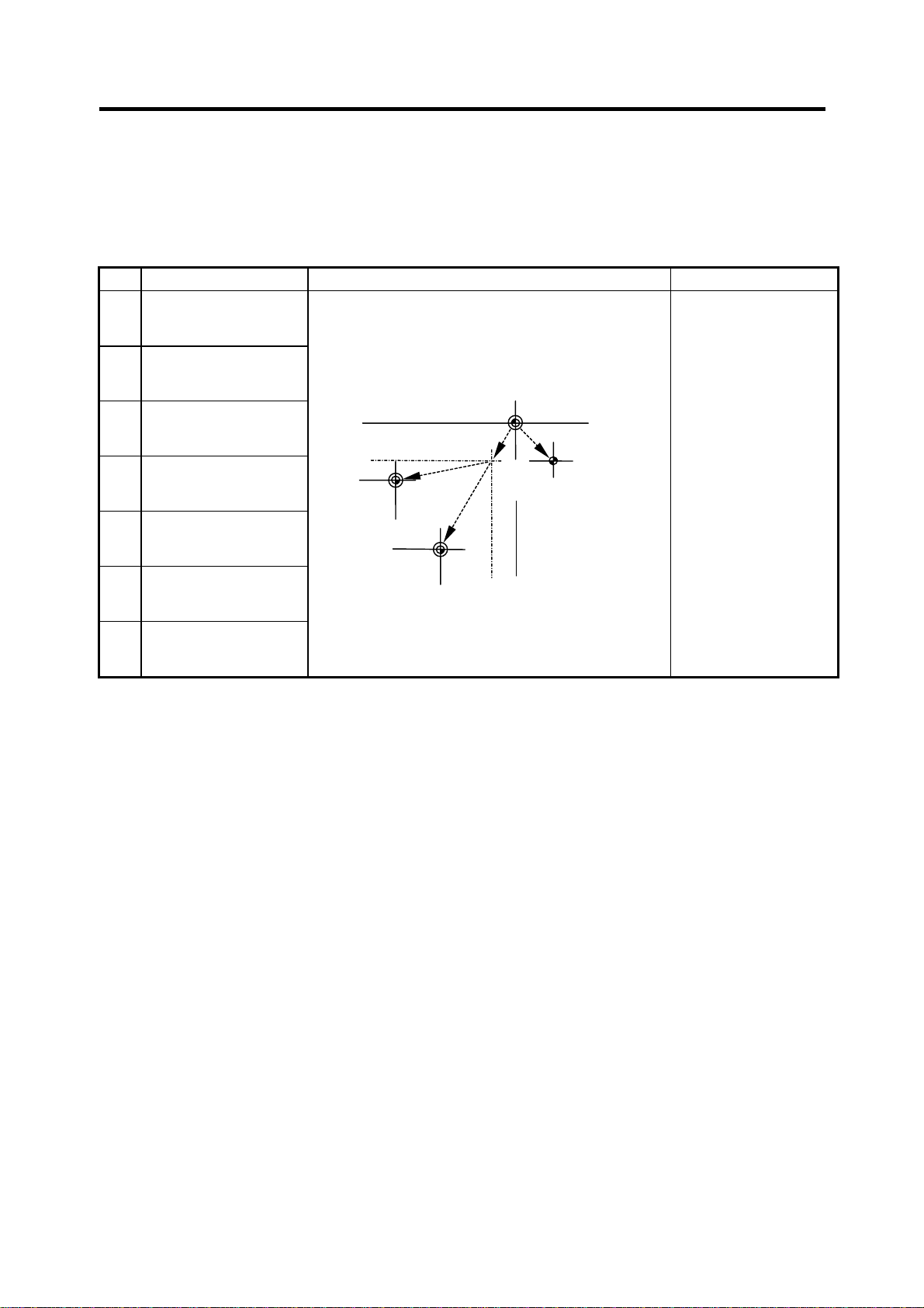
2.1 Workpiece Coordinate Offset
2. Machining Parameters
2.1 Workpiece Coordinate Offset
# Parameter Explanation Setting range (unit)
54 G54 offset
55 G55 offset
Set the workpiece coordinate system and external
workpiece coordinate offset values from G54 to G59.
The workpiece coordinate system offset data can
be set as an absolute value or incremental value.
±99999.999 (mm)
56 G56 offset
57 G57 offset
58 G58 offset
59 G59 offset
60 EXT offset
G55
workpiece
coordinate
system
Basic machine
coordinate system
W2
G54
workpiece
coordinate
system
W1
M
External
(EXT)
offset
R
Reference
point
3
Page 10

2. Machining Parameters
2.2 Process Parameters
2.2 Process Parameters
<WRK COUNT> (No. of workpieces machined)
# Item Contents Setting range (unit)
8001 WRK COUNT M Set the M code that counts the No. of workpiece
repeated machining.
The No. will not be counted when set to 0.
8002 WRK COUNT The current machining No. is displayed. Set the
initial value.
8003 WRK LIMIT Set the maximum No. of workpieces machined.
A signal is output to PLC when the No. of machining
times is counted to this limit.
<AUTO TLM> (Automatic tool length measurement)
# Item Contents Setting range (unit)
8004 SPEED Set the feedrate during automatic tool length
measurement.
8005 ZONE r Set the distance between the measurement position
and deceleration start point.
8006 ZONE d Set the tolerable zone of the measurement position.
If the sensor signal turns on in front of d before the
measurement position‚ or if the signal does not turn
on after d is passed‚ an alarm will occur.
<AUTO CORNER OVR> (Automatic corner override)
# Item Contents Setting range (unit)
8007 OVERRIDE Set the override value for automatic corner override. 0 to 100 (%)
8008 MAX ANGLE Set the max. corner opening angle where deceler-
ation should start automatically.
If the angle is larger than this value‚ deceleration will
not start.
8009 DSC. ZONE Set the position where deceleration starts at the
corner.
Designate at which length point before the corner
deceleration should start.
<T-TIP OFFSET> (Wear data input)
# Item Contents Setting range (unit)
8010 ABS. MAX.
(For L system only)
8011 INC. MAX.
(For L system only)
Set the max. value when inputting the tool wear
compensation amount.
A value exceeding this setting value cannot be set.
Set the max. value for when inputting the tool wear
offset amount in the addition mode.
0 to 99
0 to 999999
0 to 999999
1 to 1000000
(mm/min)
0 to 99999.999 (mm)
0 to 99999.999 (mm)
0 to 180 (degrees)
0 to 99999.999 (mm)
0 to 99.999 (mm)
0 to 99.999 (mm)
4
Page 11

2. Machining Parameters
2.2 Process Parameters
<FIXED C.> (Fixed cycle)
# Item Contents Setting range (unit)
8012 G73 n
(For M system only)
8013 G83 n Set the return amount for G83 (deep hole drilling
8014 CDZ-VALE
(For L system only)
8015 CDZ-ANGLE
(For L system only)
8016 G71 MINIMUM
(For L system only)
8017 DELTA-D
(For L system only)
8018 G84/G74 return
(For M system only)
<PRECISION> (High precision control)
# Item Contents Setting range (unit)
8019 R COMP Set up a compensation factor for reducing a control
8020 DCC ANGLE Set up the minimum value of an angle (external
Set the return amount for G73 (step cycle). 0 to 99999.999 (mm)
0 to 99999.999 (mm)
cycle).
Set the screw cut up amount for G76‚ 78 (thread
cutting cycle).
Set the screw cut up angle for G76‚ 78 (thread
cutting cycle).
Set the minimum cut amount for the final cutting in
G71‚ 72 (rough cutting cycle).
If the final cutting amount is smaller than this value‚
the final cut will not be performed.
Set the change amount to the command cut amount
D for G71‚ 72 (rough cutting cycle).
Each cut amount will be the value obtained by
adding or subtracting this value from command D‚
and thus‚ the amount can be changed each cut.
Set up return length m at a G84/G74 pecking tap
cycle.
(Note) Set 0 to specify a usual tap cycle.
error in the reduction of a corner roundness and
arch radius.
Indicates a maximum control error (mm) in
parentheses.
The larger the setup value, the smaller the
theoretical error will be. However, since the speed
at the corner goes down, the cycle time is extended.
angle) that should be assumed to be a corner.
When an inter-block angle (external angle) in highprecision mode is larger than the set value, it is
determined as a corner and the speed goes down to
sharpen the edge.
(Note) If “0” is set, it will be handled as 5 degrees.
The standard setting value is “0”.
If the set value is smaller than
θ
θ
, the speed goes down to
optimize the corner.
0 to 127
(0.1 lead)
0 to 89 (degrees)
0 to 99.999 (mm)
0 to 99.999 (mm)
0 to 99.999 (mm)
0 to 99 (%)
0 to 30 (degrees)
0: The angle will be 5
degrees.
5
Page 12

2. Machining Parameters
2.3 Control Parameters
2.3 Control Parameters
# Item Contents Setting range (unit)
8101 MACRO SINGLE Select the control of the blocks where the user
macro command continues.
0: Do not stop while macro block continues.
1: Stop every block during signal block operation.
8102 COLL. ALM OFF Select the interference (bite) control to the
workpiece from the tool diameter during cutter
compensation and nose R offset.
0: An alarm is output and operation stops when
an interference is judged.
1: Changes the path to avoid interference.
8103 COLL. CHK OFF Select the interference (bite) control to the work
from the tool diameter during cutter compensation
and nose R offset.
0: Performs interference check
1: Does not perform interference check
8105 EDIT LOCK B Select the edit lock for program Nos. 8000 to 9999.
0: Program can be edited.
1: Editing of above program is prohibited.
8106 G46 NO REV-ERR
(For L system only)
8107 R COMPENSATION 0: In arc cutting mode, the machine moves to the
8108 R COMP Select Specify whether to perform arc radius error
8109 HOST LINK Not used. 0
Select the control for the compensation direction
reversal in G46 (nose R offset).
0: An alarm is output and operation stops when
the compensation direction is reversed (G41
→ G42‚ G42 → G41).
1: An alarm does not occur when the compensa-
tion direction is reversed‚ and the current
compensation direction is maintained.
inside because of a delay in servo response to
a command, making the arc smaller than the
command value.
1: In arc cutting mode, the machine compensates
the movement to the inside because of a delay
in servo response to a command
correction over all axes or axis by axis.
0: Perform correction over all axes.
1: Perform correction over axis by axis.
(Note) This parameter is effective only when
"#8107 R COMPENSATION" is 1.
0/1
0/1
0/1
0/1
0/1
0/1
0/1
6
Page 13

2. Machining Parameters
2.4 Axis Parameters
2.4 Axis Parameters
# Item Contents Setting range (unit)
8201 AX. RELEASE Select the function to remove the control axis from
the control target.
0: Control as normal
1: Remove from control target
8202 OT-CHECK OFF Select the stored stroke limit function set in #8204
and #8205.
0: Stored stroke limit valid
1: Stored stroke limit invalid
8203 OT-CHECK-CANCEL When the simple absolute position method ("#2049
type" is 9) is selected‚ the stored stroke limits I, II (or
IIB) and IB will be invalid until the first reference
point return is executed after the power is turned on.
0: Stored stroke limit II valid (according to #8202)
1: Stored stroke limit II invalid
(Note) This setting (#8203) affects all the stored
stroke limits.
8204 OT-CHECK-N Set the coordinates of the (–) direction in the
moveable range of the stored stroke limit II or the
lower limit coordinates of the prohibited range of
stored stroke limit IIB.
If the sign and value are the same as #8205 (other
than "0"), the stored stroke limit II (or IIB) will be
invalid.
If the stored stroke limit IIB function is selected, the
prohibited range will be between two points even
when #8204 and #8205 are set in reverse.
When II is selected, the entire range will be
prohibited.
8205 OT-CHECK-P Set the coordinates of the (+) direction in the
moveable range of the stored stroke limit II or the
upper limit coordinates of the prohibited range of
stored stroke limit IIB.
8206 TOOL CHG. P Set the coordinates of the tool change position for
G30. n (tool change position return).
Set with coordinates in the basic machine coordinate
system.
8207 G76/87 IGNR
(For M system only)
Select the shift operation at G76 (fine boring) and
G87 (back boring).
0: Shift effective
1: No shift
0/1
0/1
0/1
–99999.999 to
+99999.999 (mm)
–99999.999 to
+99999.999 (mm)
–99999.999 to
+99999.999 (mm)
0/1
7
Page 14

2. Machining Parameters
2.5 Barrier Data
# Item Contents Setting range (unit)
8208 G76/87 (–)
(For M system only)
8209 G60 SHIFT
(For M system only)
8210 OT INSIDE The stored stoke limit function set in #8204 and
Specify the shift direction at G76 and G87.
0: Shift to (+) direction
1: Shift to (–) direction
Set the last positioning direction and distance for a
G60 (uni-directional positioning) command.
#8205 prevents the machine from moving to the
inside or outside of the specified range.
0: Inhibits outside area.
(select stored stroke limit II.)
1: Inhibits inside area.
(select stored stroke limit II B.)
0/1
–99999.999 to
+99999.999 (mm)
0/1
2.5 Barrier Data
# Item Contents Setting range (unit)
8300 P0
(For L system only)
P1
8301
P2
8302
P3
8303
P4
8304
P5
8305
P6
8306
(For L system only)
Set the reference X-coordinates of the chuck and
the tail stock barrier.
Set the center coordinate (Radius value) of
workpiece by the basic machine coordinate system.
Set the area of the chuck and tail stock barrier.
(Radius value)
Set the coordinate value from the center of workpiece
for X-axis.
Set the coordinate value by basic machine
coordinate system for Z-axis.
–99999.999 to
+99999.999 (mm)
–99999.999 to
+99999.999 (mm)
8
Page 15

3. I/O Parameters
3.1 Base Parameters
3. I/O Parameters
3.1 Base Parameters
<I/O> # <PORT No.> # <DEV. No.> <DEV. NAME>
Specify the board No. to which the serial
input/output device is connected to each
application.
DATA IN 9001 Specify the port for inputting the data
such as machine program and
parameters.
DATA OUT 9003 Specify the port for outputting the data
such as machine program and
parameters.
TAPE MODE 9005 Specify the input port for running with
the tape mode.
MACRO
PRINT
PLC IN/OUT 9009 Specify the port for inputting/outputting
REMOTE
PROG IN
9007 Specify the output port for the user
macro DPRINT command.
various data with PLC.
9011 Not used. 9012 Not used.
Set the input/output device No. for
each application.
The device Nos. are 0 to 4 and
correspond to the input/output
device parameters.
The device name set in the
input/output device parameter is
also displayed for identification.
9002 Specify the No. of the device that
inputs the data.
9004 Specify the No. of the device that
outputs the data.
9006 Specify the No. of the device to be
run with the tape mode.
9008 Specify the No. of the device for the
DPRINT command.
9010 Specify the No. of the device for the
PLC input/output.
9
Page 16
3. I/O Parameters
3.2 I/O Device Parameters
3.2 I/O Device Parameters
Parameters for up to five types of input/output devices can be set in DEV <0> to <4>.
(Note) The parameters are set for each device.
9101 ~ Set the same settings for device 0.
9201 ~ Set the same settings for device 1.
9301 ~ Set the same settings for device 2.
9401 ~ Set the same settings for device 3.
9501 ~ Set the same settings for device 4.
# Item Contents Setting range (unit)
9101
9201
9301
9401
9501
9102
9202
9302
9402
9502
9103
9203
9303
9403
9503
9104
9204
9304
9404
9504
9105
9205
9305
9405
9505
9106
9206
9306
9406
9506
DEVICE NAME 0
DEVICE NAME 1
DEVICE NAME 2
DEVICE NAME 3
DEVICE NAME 4
BAUD RATE Set the serial communication speed. 1: 9600 (bps)
STOP BIT Set the stop bit length used in the start-stop system. 1: 1 (bit)
PARITY CHECK Specify whether to add the parity check bit to the
EVEN PARITY Specify the odd or even parity when it is added to
CHR. LENGTH Set the length of the data bit. 0: 5 (bit)
Set the device name corresponding to the device
No.
Set a simple name for quick identification.
data during communication.
the data.
Use alphabet
characters‚ numerals
and symbols to set a
name within 3
characters.
2: 4800
3: 2400
4: 1200
5: 600
6: 300
7: 150
2: 1.5
3: 2
0: Parity bit not added
1: Parity bit added
0: Odd parity
1: Even parity
1: 6
2: 7
3: 8
10
Page 17

3. I/O Parameters
3.2 I/O Device Parameters
# Item Contents Setting range (unit)
9107
TERMINATOR TYPE The code to terminate data reading can be selected. 0 and 3: EOR
9207
1 and 2: EOB or EOR
9307
9407
9507
9108
HAND SHAKE Specify the transmission control method.
9208
9308
The method will be no procedure if a value except 1
to 3 is set.
9408
9508
1: RTS/CTS method
(This method can
be used only for
SIO2.)
2: No procedure (No
handshaking)
3: DC code method
DC CODE PARITY Specify the DC code when the DC code method is
9109
9209
selected.
9309
9409
0: No parity to DC
code (DC3 = 13H)
1: DC code with parity
(DC3 = 93H)
9509
DC2/DC4 OUTPUT Specify the DC code handling when outputting data
9111
9211
to the output device.
9311
9411
9511
CR OUTPUT Specify whether to insert the <CR> code just before
9112
9212
the EOB (L/F) code during output.
DC2 / DC4
0: None / None
1: Yes / None
2: None / Yes
3: Yes / Yes
0: Do not add
1: Add
9312
9412
9512
EIA Output In data output mode, select the ISO or EIA code for
9113
9213
9313
9413
data output.
In data input mode, the ISO and EIA codes are
identified automatically.
0: ISO code output
1: EIA code output
9513
FEED CHR. Specify the length of the tape feed to be output at
9114
9214
the start and end of the data during tape output.
0 to 999 (characters)
9314
9414
9514
PARITY V Specify whether to check the parity of the No. of
9115
9215
9315
9415
characters in block during data input.
The No. of characters is factory-set so that the
check is valid at all times.
0: Do not perform
parity V check
1: Perform parity V
check
9515
11
Page 18

3. I/O Parameters
3.2 I/O Device Parameters
# Item Contents Setting range (unit)
9116
TIME-OUT (s) Set the time out time to detect an interruption in
9216
9316
9416
9516
communication.
The time out is not checked when 0 is set, so the
waiting time will be infinite.
The screens cannot be changed during the waiting
time.
0 to 30 (s)
Set this time to 10 as the standard.
DR OFF Specify whether to check the DR data at the data
9117
9217
input/output.
0: DR valid
1: DR invalid
9317
9417
9517
DATA ASC II 0: Output in ISO/EIA code (Depends on whether
9118
9218
9318
9418
#9113, #9213, #9313, #9413, or #9513 EIA
output parameter is set up)
1: Output in ASC II code
0/1
9518
INPUT FORM Specify the mode for input (collation).
9119
9219
9319
9419
9519
EIA CODE [ When outputting with the EIA codes, special ISO
9121
9221
9321
9421
9521
0: Standard input (Data from the very first EOB is
handled as significant information.)
1: EOBs following the first EOB of the input data
are skipped until data other than EOB is input.
codes not included in EIA can be output with
alternate codes.
For each special code, designate a code (as a
hexadecimal) that is not duplicated with existing EIA
codes.
0/1
0 to FF (hexadecimal)
(Continued on the next page.)
]
9122
9222
9322
9422
9522
9123
#
9223
9323
9423
9523
9124
∗
9224
9324
9424
9524
12
Page 19

3. I/O Parameters
3.2 I/O Device Parameters
# Item Contents Setting range (unit)
9125
=
(Continued from the previous page.)
9225
9325
9425
9525
:
9126
9226
9326
9426
9526
9127
$
9227
9327
9427
9527
!
9128
9228
9328
9428
9528
13
Page 20
4. Setup Parameters
4. Setup Parameters
Pressing the menu key
SETUP
displays the OPEN SETUP PARAM screen.
The system’s basic parameters are normally hidden as setup parameters to prevent mistaken
operations and to simplify the display.
The setup parameters can be displayed and set by making a declaration to open the setup
parameters on this screen.
[OPEN SETUP PARAM]
Open the menu setup parameter?
*YES : "Y" "INPUT"
*NO : "N" "INPUT"
# ( )
PROCESSWORK
I/O PAR
SETUP
PARAM 3
MENU
1) Select the setup parameter.
Key-in Y in # ( )‚ and then press INPUT .
The basic specification parameter screen appears and the normally hidden setup parameter
menu will display.
The required menu can be selected to display and set the setup parameters.
2) Cancel the setup parameter selection.
Key-in N in # ( )‚ and then press INPUT .
The setup parameter menu will disappear.
(Note) The setup parameters are not displayed when the power is turned on.
Refer to "5. Base Specifications Parameters" and following for details on the setup parameters.
Be sure to turn off the power supply after selecting the setup parameter.
14
Page 21
5. Base Specifications Parameters
5. Base Specifications Parameters
After setting up the parameter (PR) listed in the table, turn off the NC power. To validate the
parameter, turn on the power again.
# Items Details
1001
(PR)
SYS_ON
Part system
validation
Specify the presence of the PLC axes and the 1st to
7th part systems with 1 or 0.
setup
1002
axisno Number of
(PR)
axes
Set No. of axes in each part system and the No. of PLC
axes.
Set so that the total of the NC axes and PLC axes is
less than the maximum number of controllable axes.
1003
iunit Input setup
(PR)
unit
Specify the input setting value for each part system
and the PLC axis. The parameter units will follow this
specification.
1013 axname Axis name Specify each axis’ name address with an alphabetic
character.
Use the characters X‚ Y‚ Z‚ U‚ V‚ W‚ A‚ B or C.
Do not specify the same address in one part system.
The same address can be specified as the other part
system.
The PLC address does not need to be set. (The axis
name is displayed as 1 and 2.)
1014 incax Increment
command
axis name
When specifying the program movement rate’s
absolute or incremental method with an address‚
specify the incremental command axis name address
with an alphabetic character.
The address that can be used is the same as "#1013
axname".
Specify an address that is different from that #1013.
Setting is not required if absolute/incremental command
with addresses is not performed ("#1076 Abslnc" = 0).
1015
cunit Command
(PR)
unit
Specify the minimum unit of the program movement
amount.
cunit Movement amount for movement command 1
10: 0.001 mm ( 1 µm)
100: 0.01 mm ( 10 µm)
1000: 0.1 mm (100 µm)
10000: 1.0 mm
If there is a decimal point in the movement command‚
the decimal point position will be handled as 1mm
regardless of this setting.
1016
iout Inch output Specify whether the machine system (ball screw pitch‚
(PR)
position detection unit) is an inch unit system or metric
unit system.
Setting range (unit)
0: Not used
1: Used
0 to 14
B: 1 µm
C: 0.1 µm
Axis addresses
such as X, Y, Z, U,
V, W, A, B, and C
100
1000
10000 1 mm
0: Metric unit
system
1: Inch unit system
10
1 µm
10 µm
100 µm
15
Page 22

5. Base Specifications Parameters
# Items Details
1017
rot Rotational
(PR)
axis
Specify whether the axis is a rotary axis or linear axis.
For the rotary axis‚ the position display will be 360
degrees‚ and the axis will return to 0 degrees.
If the position display is to be continuously displayed
even with the rotary axis‚ set the axis as a linear axis
1018
ccw Motor CCW Specify the direction of the motor rotation to the
(PR)
command direction.
0: Rotates clockwise (looking from motor shaft) with
the forward rotation command.
1: Rotates counterclockwise (looking from motor
shaft) with the forward rotation command.
1019
dia Diameter
(PR)
specification
axis
Specify whether the program movement amount is to
be commanded with the diameter dimension or as
movement amount.
When the movement amount is commanded with the
diameter dimensions‚ 5mm will be moved when the
command is a movement distance of 10mm.
The movement amount per pulse will also be halved
during manual pulse feed.
Among parameters concerning length‚ the tool length‚
the wear compensation amount and the workpiece
coordinate offset are displayed in diameter value when
diameter is specified‚ but other parameters are always
displayed in radius value.
1020
sp_ax Spindle
(PR)
Interpolation
Specify 1 when the NC control axis is used as the
spindle.
Setting range (unit)
0: Linear axis
1: Rotary axis
0: Rotates
clockwise
1: Rotates
counterclockwise
0: Command with
movement
amount
1: Command with
diameter
dimension
0: The NC control
axis is used as
the servo axis.
1: The NC control
axis is used as
the spindle.
16
Page 23

5. Base Specifications Parameters
# Items Details
1025 l_plane Initial plane
selection
Specify the plane to be selected when the power is
turned on or reset.
When 0 is specified, 1 is assumed (X-Y plane).
1026
1027
1028
base_l
base_J
base_K
Base axis I
Base axis J
Base axis K
Specify the basic axis address that composes the
plane.
Specify the axis address set in “#1013 axname”.
Set the axis name even when there is no need to
configure a plane, such as the case of 2-axis
specifications.
Normally‚ when X‚ Y and Z are specified respectively
for base_l‚_J‚_K‚ the following relation will be
established:
G17: X-Y
G18: Z-X
G19: Y-Z
Specify the desired address to set an axis address
other than the above.
1029 aux_I Flat axis I If there is an axis parallel to "#1026 base_l"‚ specify
that axis address.
1030 aux_J Flat axis J If there is an axis parallel to "#1027 base_J"‚ specify
that axis address.
1031 aux_K Flat axis K If there is an axis parallel to "#1028 base_K"‚ specify
that axis address.
Setting range (unit)
: X-Y plane (G17
1
command state)
2: Z-X plane (G18
command state)
3: Y-Z plane (G19
command state)
Control axis
addresses such as
X, Y, and Z
Control axis
addresses such as
X, Y, and Z
Control axis
addresses such as
X, Y, and Z
Control axis
addresses such as
X, Y, and Z
17
Page 24
5. Base Specifications Parameters
# Items Details
1037 cmdtyp Command
type
Specify the program G code series and compensation
type.
cmdtyp G code series Compensation type
1 System 1 (for M) Type A (one compensation
amount for one compensation number)
2 System 2 (for M) Type B (shape and wear
amounts for one compensation number)
System 2 (for L) Type C (two kinds of
3
System 3 (for L) Same as above
4
System 4
5
(for special L)
System 5
6
(for special L)
System 6
7
(for special L)
System 7
8
(for special L)
compensation amount of
shape and wear per
compensation No.)
Same as above
Same as above
Same as above
Same as above
Setting range (unit)
1 to 8
1038 plcsel Ladder
selection
There are some items in the specifications that can be
used or cannot be used according to the value set in
this parameter.
The file structure may also change depending on the
compensation data type.
Thus‚ after changing this parameter‚ initialize the
system with "#1060 SETUP".
# (1060) DATA ( 1) ( )
INPUT
↓
"BASE PARA SET? (Y/N)" : N
INPUT
↓
"FORMAT? (Y/N)" : Y
INPUT
↓
"SETUP COMPLETE"
(Note) The machining program is cleared with the
above operations. Back up necessary
machining programs in an external memory
before initializing.
Specify the PLC type. 0 to 2
18
Page 25
5. Base Specifications Parameters
# Items Details
1039 spinno Number of
spindles
Specify the existence of a spindle.
0: No spindle 4: Four spindles
1: One spindle 5: Five spindles
2: Two spindles 6: Six spindles
3: Three spindles 7: Seven spindles
1040
M_inch Constant
(PR)
1041
l_inch Initial state
(PR)
input (inch)
(inch)
Specify the parameter unit system for the position and
length.
Specify the unit system for the program movement
amount when the power is turned on or reset and for
position display.
1042
pcinch PLC axis
(PR)
command
Specify the unit system for the commands to the PLC
axis.
(inch)
1043 lang Select
language
displayed
Specify the display language.
0 : Japanese display
1 : English display
21: Polish display
(Note) If no character package is available for a
specified language, the screen is displayed in
English.
1044
auxno MR-J2-CT
(PR)
connections
Specify the number of MR-J2-CT axes connected.
As for C6/C64 system, up to 5 axes of MR-J2-CT can
be connected, thus, the setting range is 0 to 5.
(Note) Selection of inch and metric unit
When set value of "#1041 I_inch" is changed‚ the unit of length is changed after reset.
Among parameters concerning length‚ following items are not changed automatically‚ therefore
change the set values to agree with the new unit system when the unit system is changed.
Tool compensation amount
(Tool length compensation amount‚ tool wear compensation amount and tool tip compensation amount)
Workpiece coordinate offset
Machining parameter #8004 SPEED #8013 G83n #8052 PULL UP
#8005 ZONE r #8016 G71 MINIMUM #8053 G73U
#8006 ZONE d #8017 G71 DELTA-D #8054 W
#8009 DSC. ZONE #8018 G84/G74n #8056 G74 RETRACT
#8010 ABS. MAX. #8027 Toler-1 #8057 G76 LAST-D
#8011 INC. MAX. #8028 Toler-2
#8012 G73n #8051 G71 THICK
Axis parameter #8204 OT-CHECK-N
#8205 OT-CHECK-P
#8206 TOOL CHG.P
#8209 G60 Shift
Barrier data #8300 – #8306
Basic specification
parameter
#1084 RadErr
#8004 SPEED is 10 inches/min. unit for the inch system.
Setting range (unit)
0 to 7
0: Metric system
1: Inch system
0: Metric system
1: Inch system
0: Metric system
1: Inch system
0/1/21
0 to 7
19
Page 26
5. Base Specifications Parameters
N
# Items Details
1060 SETUP Activate
setup
processing
Execute the functions required for initializing the
system.
“BASE PARA. SET? (Y/N)” is displayed.
Setting range (unit)
1
INPUT
1061
(PR)
intabs Manual ABS
updating
INPUT
Y
“FORMAT? (Y/N)” is displayed.
INPUT
Y
“SETUP COMPLETE” is displayed.
N
INPUT
INPUT
(Note) Most setup parameters will be initialized with
one-touch setup‚ so confirm the data before
executing.
This parameter will automatically be set to 0 when the
power is turned on.
Defines whether to update the absolute value data
during automatic handle interrupt.
This parameter is valid only when "#1145 l_abs" is set
to 1.
0: Does not update
(shift coordinates
by the amount of
the interruption)
1: Updates (same
coordinates as
when interrupt did
not occur will be
applied.)
20
Page 27
5. Base Specifications Parameters
# Items Details
1062 T_cmp Tool offset
function
Specify whether the tool length offset and wear
compensation is valid during T command execution.
Setting value Tool length offset Wear compensation
0 Valid Valid
1 Valid Invalid
2 Invalid Valid
3 Invalid Invalid
1063 mandog Manual
dog-type
The initial return to the reference point is performed
with dog-type return after the power is turned on‚ and
the coordinate system is established.
Specify the manual reference point return method
after the coordinate system is established with this
parameter.
(This setting is not required when using absolute
position detection.)
1064
(PR)
1065 JOG_H JOG
svof Error
correction
response
type
Specify whether to correct the error when the servo is
off.
Set up an improved JOG response type.
0: Conventional specification
The system is started and stopped by signals
via ladder without reference to external input
signals.
1: Type 1
The system is started up and stopped by
external signals.
2: Type 2
The system is started up and stopped by
performing the AND operation for external
signals and signals via ladder.
3: Type 3
The system is started up when signals via
ladder rise. It is stopped when external signals
and signals via ladder fall.
4: Type 4
Reference point return mode:
The system is started up and stopped by
signals via ladder without reference to
external input signals (conventional
specification).
Non-reference point return mode:
The system is started up and stopped by
performing AND for external signals and
signals via ladder (type 2).
Setting range (unit)
0 to 3
0: High speed
return
1: Dog-type
0: Does not
correct the error
1: Corrects the
error
0 to 4
21
Page 28

5. Base Specifications Parameters
# Items Details
JOG_HP
1066
Select JOG
activation
(+) device
Specify the number of the device that inputs +JOG
activation signals. The device type is specified by
"#1071 JOG_D". The effective range of set values vary
depending on the device type. A value outside of the
effective range is invalid if specified.
(Note) The setting range of this parameter has been
expanded on the software Ver.D0 and later.
JOG_HN
1067
Select JOG
activation
(−) device
Specify the number of the device that inputs -JOG
activation signals. The device type is specified by
"#1071 JOG_D". The effective range of set values vary
depending on the device type. A value outside of the
effective range is invalid if specified.
(Note) The setting range of this parameter has been
expanded on the software Ver.D0 and later.
1068
slavno Slave axis
(PR)
number
Specify the axis number of a slave axis to be
synchronized. The axis number is an NC number
excluding the spindle and PLC axis.
Two or more slave axes cannot be set up for one
master axis.
This parameter "slavno" cannot be set up for a slave axis.
A multiple part system cannot be set up so that the
relation between the master and slave axes extends
over a part system.
1069
no_dsp Axis with no
(PR)
counter
display
1070 axoff Axis
Set up an axis that displays no counter. This option is
valid on the counter display screen (e.g. POSITION
screen).
Define an axis that enables axis removal control. 0: Disables axis
removal
Setting range (unit)
X: 0000 to 03FF
(hexadecimal)
M: 0000 to 8191
(decimal)
X: 0000 to 03FF
(hexadecimal)
M: 0000 to 8191
(decimal)
0: No slave axis
1 to 6: First to
sixth axes
0: Displays the
counter
1: Does not
display the
counter.
removal.
1: Enables axis
removal
1071
(PR)
JOG_D
±JOG
activation
signal
device
name
Specify the number of the device that inputs ±JOG
activation signals.
0 : X device
1 or 2: M device
Set the JOG_HP (#1066) and JOG_HN (#1067)
parameters according to this device specification
parameter.
(Note) The setting range of #1066 and #1067
parameters has been expanded on the software
Ver.D0 and later.
22
0 to 2
Page 29

5. Base Specifications Parameters
# Items Details
1073 I_Absm Initial
absolute
Specify the absolute value/incremental value mode for
when the power is turned on or reset.
value
1074 l_Sync Initial
synchronous
feed
Specify the feedrate specification mode for when the
power is turned on or reset.
0: Asynchronous feed (feed per minute)
1: Synchronous feed (feed per rotation)
1075 I_G00 Initial G00 Specify the linear command mode for when the power
is turned on or reset.
0: Linear interpolation (G01 command state)
1: Positioning (G00 command state)
1076 Abslnc
(For L
system
only)
ABS/INC
address
The absolute value/incremental commands can be
issued by using the absolute value address and
incremental value address for the same axis.
0: Absolute/incremental with G command
1: Absolute/incremental with address code
(The "#1013 axname" address will be the
absolute value command‚ and "#1014 incax"
address will be the incremental value command)
1077 radius Incremental
command
for diameter
Specify if the diameter specification axis’ ("#1019 dia" is
set to 1) incremental value command uses the diameter
value or radius value
specification
axis
1078 Decpt2 Decimal
point type 2
Specify the unit of position commands that do not have
a decimal point.
0: The min. input command unit is used (follows
"#1015 cunit")
1: 1mm (or 1inch) unit is used
1079 F1digt Validate F1
digit
Specify whether to execute the F command with a
1-digit code command or with a direct numerical
command.
0: Direct numerical command (command feedrate
during feed per minute or rotation)
1: 1-digit code command (feedrate specified with
"#1185 spd_F1" to "#1189 F5")
Setting range (unit)
0: Incremental
value command
mode
1: Absolute value
command
mode
0: Asynchronous
feed
1: Synchronous
feed
0: Linear
interpolation
1: Positioning
0: Absolute/
incremental
with G
command
1: Absolute/
incremental
with address
code
0: Diameter value
1: Radius value
0: The min. input
command unit
is used
1: 1mm (or 1inch)
unit is used
0: Direct
numerical
command
1: 1-digit code
command
23
Page 30

5. Base Specifications Parameters
# Items Details
1080 Dril_Z
(For M
system
only)
Specify
boring axis
Specify a fixed-cycle boring axis.
0: Uses an axis perpendicular to the selected plane
as the boring axis.
1: Uses the Z axis as the boring axis regardless of
the selected plane.
1081
Gmac_P
Give priority
to G code
parameter
Specify the G code priority relationship during the
macro call with the G command.
0: G code used in system is priority
1: Registered G code for call out is priority
1082 Geomet
(For L
system
only)
Geometric Specify the validity of the geometric function.
As the designated address code is used exclusively for
geometric‚ if "A" or "C" is used for the axis address or
2nd miscellaneous command code‚ "A" that is the axis
address may be handled as the geometric’s angle
specification. Take special care to the setting of the
axis name‚ etc.‚ when using this function.
1084 RadErr Arc error Specify the tolerable error range when a deviation
occurs in the end point and center coordinate in the
circular command.
1085 G00Drn G00 dry run Specify whether to apply dry run (feed with manual
setting speed instead of command feedrate) to the G00
command.
0: Does not apply to G00 (moves at rapid traverse
feedrate)
1: Applies to G00 (moves at manual set feedrate)
1086 G0lntp G00 non-
interpolation
Specify the G00 movement path type
0: Moves linearly toward the end point (interpolation
type)
1: Moves to the end point of each axis at the rapid
traverse feedrate for each axis
(non-interpolation)
1087
G96_G0
Constant
surface
speed
control by
rapid
traverse
feed
Specify how to handle the cycle speed for the G00
command when using the constant surface speed
control function.
0: Calculates the cycle speed constantly even
during G00 movement.
1: Calculates the cycle speed at the block end point
in the G00 command.
command
Setting range (unit)
0/1
0/1
0: Invalid
1: Valid
0 to 1.000 (mm)
0/1
0/1
0/1
24
Page 31

5. Base Specifications Parameters
# Items Details
1088 G30SL Disable G30
soft limit
Specify how to handle the soft limit during G30 (2nd
reference point return) movement.
0: Soft limit valid during G30 movement
1: Soft limit invalid during G30 movement
1089 Cut_RT Short cut for
rotary axis
Specify how to handle the short cut control for the
rotary axis ("#1017 rot" is set to 1).
0: No short cut (move toward end point)
1: Uses short cut (when using the absolute value
command‚ move in the direction where the
movement amount will be 180 degrees or less)
1090 Lin_RT Linear
rotary axis
Specify how to handle a command for the rotary axis
that exceeds 360 degrees.
0: For absolute value commands that exceed 360
degrees‚ the value will be converted into a
remainder of 360 degrees and the axis will move.
Example: If the command is 420 degrees‚ the
applied value will be 60 degrees.
1: For absolute value commands that exceed 360
degrees‚ the axis will move in the same manner
as a linear axis.
Example: If the command is 420 degrees‚ the axis
will pass the 360 degree position and
will move to the 60 degree position.
1091 Mpoint Ignore
middle point
Specify now to handle the middle point during G28 and
G30 reference point return.
0: Moves to the reference point after passing the
middle point designated in the program.
1: Ignores the middle point designated in the
program and move straight to the reference point.
1092
Tchg _A
Replace
tools for
additional
axis
Specify the movement of the additional axis during tool
change position return.
0: The additional axis does not move with the tool
change position return command.
1: After returning the standard axis with the tool
change position return command‚ the additional
axis also returns to the tool change position.
1093 Wmvfin Waiting
method
between
part systems
Specify the method for waiting between part systems.
When the movement command is found in the wait
command ! block:
0: Waits before executing movement command
1: Waits after executing movement command
1094 Tl_SBK
(for L
system
only)
Select life
count for
single block
Select whether to count the data units to be used for a
single block when using the tool life management II
function (lathe system).
0: Does not count the data units.
1: Count the data units.
Setting range (unit)
0/1
0: No short cut
1: Use short cut
0/1
0/1
0/1
0/1
0/1
25
Page 32

5. Base Specifications Parameters
# Items Details
1095 T0tfof TF output Select how to handle TF for T00 command.
0: TF is output.
1: TF is not output
1096 T_Ltyp
(For L
system
only)
Tool life
management
type
1097 T1digt Tool wear
compensation
number
1-digit
command
Specify the tool life management type. 1: Life manage-
Specify the No. of digits in the tool wear compensation
No. in the T command.
0: The 2 high-order digits are the tool No.‚ and the 2
low-order digits are the wear compensation No.
1: The 3 high-order digits are the tool No.‚ and the 1
low-order digit is the wear compensation No.
This parameter will be fixed to 0 when tool life management II is selected.
1098 Tlno. Tool length
offset
number
Specify the No. of digits in the tool length offset No. in
the T command.
0: The 2 or 3 high-order digits are the tool No.
The 2 or 1 low-order digits are the tool length
offset and wear compensation Nos.
1: The 2 or 3 high-order digits are the tool No. and
tool length offset Nos.
The 2 or 1 low-order digits are the wear
compensation No.
1099 Treset Cancel tool
wear
compensation
amount
Specify how to handle tool compensation vector when
resetting system.
0: Clears the tool length and wear compensation
vectors when resetting.
1: Saves the tool length and wear compensation
vectors when resetting.
When the values are cleared‚ the compensation will
not be applied‚ so the axis will move the compensation
amount in the next compensation operation.
When the values are saved‚ the compensation will be
applied‚ so the axis will shift the differential amount of
the compensation amount in the next compensation
operation.
Setting range (unit)
0/1
ment type l
2: Life manage-
ment type ll
0/1
0/1
0: Clears
1: Saves
26
Page 33

5. Base Specifications Parameters
# Items Details
1100 Tmove Tool wear
compensation
Specify the period to perform tool length offset and
wear compensation.
0: Compensate when T command is executed.
1: Superimpose and compensate with the
movement command in the block where the T
command is located. If there is no movement
command in the same block‚ compensation will
be executed after the movement command is
superimposed in the next movement command
block.
2: Compensate when the T command is executed.
1: Superimpose and compensate a tool length
offset with the movement command in the same
block. If there is no movement command in the
same block, compensation will be executed after
the movement command is superimposed in the
next movement command block.
1101 Tabsmv Tool wear
compensation
method
Specify the type of movement command when "#1100
Tmove" is set to 1.
0: Compensate regardless of the movement
command type.
1: Compensate only at the movement command in
the absolute value command.
1102 tlm
(For L
system
only)
Manual tool
length
measuring
system
1103 T_life Validate life
Specify the measurement method for manual tool
measurement l.
0: Align tool with basic position
1: Input measurement results
Select the usage of the tool life management function. 0: Do not use.
management
1104
T_Com2
Tool
command
method 2
Select the command method for when "#1103 T_Life"
is set to 1.
0: Handle the program tool command as the group
No.
1: Handle the program tool command as the tool
No.
Setting range (unit)
0 to 2
0: Compensate
regardless of
the command
type.
1: Compensate
only with the
absolute value
command.
0: Basic position
method
1: Measured
value input
method
1: Perform tool life
management
control.
0/1
27
Page 34

5. Base Specifications Parameters
# Items Details
1105 T_Sel2 Tool
selection
method 2
Select the tool selection method for when "#1103
T_Life" is set to 1.
0: Select in order of registered No. from the tools
used in the same group.
1: Select the tool with the longest remaining life
from tools used in the same group and the
unused tools.
1106 Tcount
(For L
system
Life management count
Specify the function when address N is omitted when
inputting data (G10 L3 command) for tool life management function ll.
only)
1107 Tllfsc
(For L
system
only)
Split life
management
display
screen
Set up the number of groups to be displayed on the
tool life management II (lathe system) screen.
0: Displayed group count 1
1: Displayed group count 2
2: Displayed group count 4
1108 TlrectM
(For L
system
only)
1109
subs_M Validate
(PR)
Life management
re-count M
code
alternate M
Set up the M code for tool life management II (lathe
system) re-count.
Select the user macro interrupt with the substitute M
code.
code
1110 M96_M M96
alternate M
Specify an M code to replace M96 when "#1109
subs_M" is set to 1.
code
1111 M97_M M97
alternate M
Specify an M code to replace M97 when "#1109
subs_M" is set to 1.
code
1112
S_TRG Validate
(PR)
status trigger
system
Specify the validity conditions for the user macro
interrupt signal.
0: Valid when interrupt signal (UIT) turns off to on.
1: Valid when interrupt signal (UIT) is ON.
1113
INT_2 Validate
(PR)
interrupt
method type
2
Specify the movement after user macro interrupt
signal (UIT) input.
0: Execute interrupt program without waiting for
block being executed to end.
1: Execute interrupt program after completing block
being executed.
Setting range (unit)
0/1
0: Time specified
input
1: No. of times
specified input
0 to 2
0 to 99
0: Alternate M
code invalid
1: Alternate M
code valid
3 to 97
(excluding 30)
0: Valid when
interrupt signal
(UIT) turns off
to on.
1: Valid when
interrupt signal
(UIT) is ON.
0/1
28
Page 35

5. Base Specifications Parameters
# Items Details
1114 mcrint Macro
argument
initialization
Select whether to clear statements other than
specified arguments by macro call. Also, select
whether to clear local variables by power-on and
resetting.
0: Delete non-specified arguments by macro call.
1: Retain non-specified arguments by macro call.
2: Retain non-specified arguments by macro call
and clear local variables by power-on and
resetting.
1115 thwait Waiting for
thread cutting
Set the queue number during screw thread cutting
when the chamfering is not valid.
1116
G30SLM
Invalidate
soft limit
(manual
Enable this function when disabling the soft limit check
function from the second to the fourth reference point
return by manual operation.
operation)
1117 H_sens Handle
response
switch
Switch the handle response mode when feeding the
handle.
0: Standard handle response
1: High-speed handle response
1118 mirr_A
(For L
system
only)
Select how to
set up the
length of
tools on
facing turret
Select one of the following two methods.
0: Set up the current length of tools on facing turret.
1: Set up a value, assuming that the tools on facing
turret is in the same direction as that of those on
the base turret.
(double-turret
mirror image)
1119 Tmiron
(For L
system
only)
Select the
double-turret
mirror image
with T
Select whether to validate the double-turret mirror
image with the T command.
command
1120
TofVal Change
(PR)
macro
variable
Specify whether to change the macro variable (tool
offset) numbers for shape compensation and wear
compensation.
0: Do not change. (Conventional specifications)
1: Change the shape and wear compensation
variable numbers each for X, Z, and R.
Setting range (unit)
0/1/2
0 to 99 (Approx. 4
ms.)
Standard set value:
4
0: Enable soft limit
function.
1: Disable soft
limit function.
0/1
0/1
0: Invalid
1: Valid
0/1
29
Page 36

5. Base Specifications Parameters
# Items Details
1121 edlk_c Edit lock C Specify whether to prohibit editing of program Nos.
9000 to 9999.
1122
pglk_c Program
(PR)
display lock
The display and search of program Nos. 9000 to 9999
can be prohibited. Specify whether to prohibit display
and search.
0: Display and search is possible
1: Program details are not displayed
2: Program details are not displayed‚ and operation
search is prohibited.
The program details will not be displayed‚ but the
program No. and sequence No. will display in the
prohibited state.
1123 origin Origin zero
Select whether to use the origin zero function. 0: Use
inhibition
1124 ofsfix Fix tool wear
compensation
number
Specify whether to automatically increment the offset
No. by 1 with the input or to display the No. as it is in
the setting on the tool offset screen.
0: Increment the # No. by 1 when the input key is
pressed. (Same as general parameters)
1: # No. does not change even if input key is
pressed.
When making settings in sequence‚ 0 is handier.
When changing and setting repeatedly while adjusting
one offset value‚ 1 is handier
1125 real_f Actual
Specify the feedrate display on the monitor screen. 0: Command
feedrate
display
1126
1127
PB_G90
DPRINT
Not used. 0
DPRINT
alignment
Specify the alignment for printing out with the DPRINT
function.
0: No alignment‚ data is printed with left
justification.
1: Align the minimum digit and output.
Setting range (unit)
0: Editing
possible
1: Editing
prohibited
0 to 2
1: Do not use
0/1
speed
1: Real move-
ment feedrate
0/1
30
Page 37

5. Base Specifications Parameters
# Items Details
1128 RstVCI Clear
variables by
resetting
Specify how to handle the common variables when
resetting.
0: Common variables do not change after resetting.
1: The following common variables are cleared by
resetting:
During variable 100 sets specifications:
#100 to #149 are cleared.
During variable 200 or 300 sets specifications:
#100 to #199 are cleared.
1129 PwrVCl Clear
variables by
power-on
Specify how to handle the common variables when the
power is turned on.
0: The common variables are in the same state as
before turning the power off.
1: The following common variables are cleared
when the power is turned on.
During variable 100 sets specifications:
#100 to #149 are cleared.
During variable 200 or 300 sets specifications:
#100 to #199 are cleared.
1130 set_t Display
selected tool
number
Specify the tool command value display on the
POSITION screen.
0: T-modal value of program command is displayed.
1: Tool number sent from PLC is displayed.
1131
Fldcc Feed forward
(PR)
filter
Parameter to suppress acceleration changes with a
filter when starting acceleration or deceleration.
Specify the parameter in bits.
76543210
Feed forward filter
1132 CRT CRT
brightness
control
This parameter adjusts the brightness of the CRT
display unit.
–3: Highest luminance (Brightest state)
–3: Lowest luminance (Darkest state)
Adjust this parameter to an appropriate brightness
between –3 and 3.
The EL display unit does not have brightness
adjustment‚ so setting is not required.
Setting range (unit)
0/1
0/1
0/1
bit1: 7.1 (ms)
bit2: 14.2 (ms)
bit3: 28.4 (ms)
bit4: 56.8 (ms)
If bit 1 to bit 4 are
all 0 or two or more
bits of bit 1 to bit 4
are 1, 3.5 ms is set
up.
–3 to 3
31
Page 38

5. Base Specifications Parameters
# Items Details
1133 ofsmem Select how
to set up tool
wear
compensation screen
Select the number stored by previous setup when
selecting the tool wear compensation screen.
0: Does not display the number when selecting the
screen.
1: Displays the stored number when selecting the
screen.
1134 LCDneg LCD reverse
display
Specify 1 to reverse the display on the 10.4-type
monochrome LCD.
1135 unt_nm Unit name Set up a unit name.
Set up the unit name with 4 or less characters consisting
of both alphabets and numbers. If 0 is set up, the unit
name is not displayed.
1138 Pnosel Not used. 0
1139 edtype Edit type
selection
Set up an edit type.
0: Screen edit type (M50 or equivalent operation)
1: Screen edit type (The screen of EDIT or MDI is
changed automatically according to the selected
operation mode.)
2: Word edit type (The screen of EDIT or MDI is
changed automatically according to the selected
operation mode.)
1140 Mn100 M code
number
1141 Mn200 M code
number
1142 Mn300 M code
number
1143 Mn400 M code
number
1144 mdlkof MDI setup
First number of M code that corresponds to setup
number from 100 to 199.
First number of M code that corresponds to setup
number from 200 to 299.
First number of M code that corresponds to setup
number from 300 to 399.
First number of M code that corresponds to setup
number from 400 to 499.
Select whether to enable MDI setup in non-MDI mode. 0: Disable MDI
lock
Setting range (unit)
0/1
0: Normal display
1: Reverse display
4 or less characters
consisting of both
alphabets and
numbers
0/1/2
0 to 99999999
0 to 99999999
0 to 99999999
0 to 99999999
setup
1: Enable MDI
setup
32
Page 39

5. Base Specifications Parameters
# Items Details
1145 I_abs Manual ABS
parameter
Specify how to handle the absolute position data during
automatic handle interrupt.
0: Absolute position data is renewed if manual ABS
switch is on. Data is not renewed if switch is off.
1: Follows the intabs state when "#1061 intabs" is
valid.
1146 Sclamp Spindle
rotation
clamp
function
Specify how to handle the spindle rotation clamp
function with the G92S command.
0: G92S command is handled as a clamp command
only in the G96 state (during constant surface
speed control). G92S will be handled as normal S
command in G97 state (constant surface speed
OFF).
1: The S command in the same block as G92 is
constantly handled as a clamp command.
1147 smin_V Minimum
spindle
rotation
speed clamp
type
Specify the type of spindle min. rotation speed clamp
value.
0: Rotation speed setting
1: Output voltage coefficient setting
Set the "#3023 smini" parameter according to this type
setting.
1148 I_G611 Initial high
precision
Specify the default mode after power-on or resetting.
0: G64 (cutting mode)
1: G61.1 (high precision control mode)
1149 cireft Arc
deceleration speed
change
1150 F1dc0 G00 feed
forward filter
Specify whether to enable deceleration at the arc
entrance or exit.
0: Disable
1: Enable
This parameter is used to filter acceleration changes at
the start of rapid acceleration/deceleration. Specify
the filters in bit units.
7 6 5 4 3 2 1 0
G00 feed forward filter
Feed forward filter
G00 and G01 independent
0: Common 1: Independent
Setting range (unit)
0/1
0/1
0: Rotation speed
setting
1: Output voltage
coefficient
setting
0/1
0/1
bit1: 7.1 (ms)
bit2: 14.2 (ms)
bit3: 28.4 (ms)
bit4: 56.8 (ms)
If bit 1 to bit 4 are all
0 or two or more
bits of bit 1 to bit 4
are 1, 3.5 ms is set
up.
1151 rstint Reset initial Specify whether to initialize various modals by
resetting.
0: Does not initialize.
1: Initializes.
33
0/1
Page 40

5. Base Specifications Parameters
# Items Details
1152 I_G20 Initial
command
unit
Specify whether the default mode after power-on or
resetting, inch command or metric command mode.
0: Metric command (G21 command state)
1: Inch command (G20 command state)
Valid when reset input is made.
Related parameter: Bit 6 "Select setting and display
unit" of #1226
1154
pdoor Door
(PR)
interlock II
(for each part
system)
Specify whether to control door interlock II
independently for each of the two part systems.
When door interlock II is controlled for each part
system of the two part systems, part system 1 is
connected to SERVO1 of the base I/O unit and part
system 2 is connected to SERVO2 of the base I/O unit.
C6/C64 unit
SERVO1
AMP AMP
AMP
SERVO2
AMP AMP
AMP
When the auxiliary axis (MR-J2-CT) is used, connect it
to the SERVO2 side (after the spindle). This validates
door interlock II of part system 2.
0: Do not use door interlock II independently for
each part system.
1: Use door interlock II independently for each part
system.
When 0 is specified for this parameter, "Signal input
device 1 for door interlock II (#1155 DOOR_m)" and
"Device number 2 for door interlock II signal input
(#1156 DOOR_s) are valid. When 1 is specified,
"Signal input device 1 for door interlock II: for each part
system (#1511 DOORPm)" and "Signal input device 2
for door interlock II: for each part system (#1512
DOORPs)."
Setting range (unit)
0/1
0/1
Part system 1
Part system 2
34
Page 41

5. Base Specifications Parameters
# Items Details
DOOR_m
1155
Signal input
device 1 for
door interlock
II
Set up a fixed device number (X??) for door interlock II
signal input.
A device number from X001 to X3FF can be set up.
Device number 000 is invalid. Set up device number
100 when using no fixed device number for door
interlock II signal input.
(Note) The setting range of this parameter has been
expanded on the software Ver.D0 and later.
Related parameter: "#1154 pdoor" Door interlock II
(for each part system)
DOOR_s
1156
Device
number 2 for
door interlock
II signal input
Set up a fixed device number (X??) for door interlock II
signal input. (Set up the same value as that of #1155.)
(Note) The setting range of this parameter has been
expanded on the software Ver.D0 and later.
Related parameter: "#1154 pdoor" Door interlock II
(for each part system)
1157 F0atrn F0 automatic
Not used.
running
1158 F0atno F0 automatic
Not used.
running
program
1166 fixpro Fixed cycle
editing
Select whether to use the edit‚ program list‚ and data
input/output functions for the fixed cycle or general
program.
0: Editing‚ etc.‚ of general program will be possible.
1: Editing‚ etc.‚ of fixed cycle will be possible.
1167 e2rom Not used.
1168 test Simulation
test
Specify the test mode for the control unit.
The test mode does not use reference point return‚ and
tests with a hypothetical reference point return
completed state. This is limited to test operation of the
control unit itself‚ and must not be used when
connected to the machine.
Setting range (unit)
000 to 3FF
(hexadecimal)
000 to 3FF
(hexadecimal)
0/1
0: Normal
operation mode
1: Test mode
35
Page 42

5. Base Specifications Parameters
# Items Details
1169 system
name
Part system
name
Set the name of each part system.
This must be set when using the multiple part system.
This name is displayed on the screen only when the
part systems must be identified.
Use a max. of four alphabetic characters or numerals.
1170 M2nameSecond
miscellaneous code
1171 taprov Tap retract
override
1172 tapovr Tap retract
override
Set this address code when using the 2nd miscellaneous command. Set an address with A‚ B and C that is
not used with "#1013 axname" or "#1014 incax".
Set the tap retract override value for the synchronous
tap.
Set the override value when leaving the tap end point in
the synchronous tap cycle.
The setting range is 1 to 999‚ and the unit is %.
When a value less than 100 is set‚ it will be judged as
100%.
1173 dwlskp G04 skip
condition
Specify the skip signal for ending the G04 (dwell)
command.
Setting
10 { × { ×
11 { × { {
12 { { × ×
13 { { × {
14 { { { ×
15 { { { {
SKIP3 SKIP2 SKIP1 SKIP0
0 × × × ×
1 × × × {
2 × × { ×
3 × × { {
4 × { × ×
5 × { × {
6 × { { ×
7 × { { {
8 { × × ×
9 { × × {
Skip signals
Skip when { signal is input.
1174 skip_F G31 skip
speed
Specify the feedrate when there is no F command in
the program at G31 (skip) command.
Setting range (unit)
A max. of four
alphabetic
characters or
numerals.
A, B, C
1 to 100 (%)
1 to 999 (%)
0 to 15
1 to 999999
(mm/min)
36
Page 43

5. Base Specifications Parameters
# Items Details
1175
1176
1177
1178
1179
1180
skip1
1f
2
2f
3
3f
G31.1 skip
condition
G31.1 skip
speed
G31.2 skip
condition
G31.2 skip
speed
G31.3 skip
condition
G31.3 skip
Specify the skip signal in the G31.1 to G31.3 (multi-step
skip) command‚ and the feedrate when there is no F
command in the program.
Setting
10 { × { ×
11 { × { {
12 { { × ×
13 { { × {
14 { { { ×
15 { { { {
SKIP3 SKIP2 SKIP1 SKIP0
0 × × × ×
1 × × × {
2 × × { ×
3 × × { {
4 × { × ×
5 × { × {
6 × { { ×
7 × { { {
8 { × × ×
9 { × × {
Skip signals
Skip when { signal is input.
Skip signal specified at G31.1
Skip feedrate at G31.1
Skip signal specified at G31.2
Skip feedrate at G31.2
Skip signal specified at G31.3
Skip feedrate at G31.3
speed
Setting range (unit)
Skip condition:
0 to 15
Skip federate:
1 to 999999
(mm/min)
37
Page 44

5. Base Specifications Parameters
# Items Details
1181 G96_ax Constant
surface
speed
control
Specify the axis to be targeted for constant surface
speed control.
0: Program specification will be invalidated‚ and the
axis will always be fixed to the 1st axis.
1: 1st axis specification
2: 2nd axis specification
3: 3rd axis specification
4: 4th axis specification
The program specification will be the priority for all
settings other than 0.
1182 thr_F Thread
cutting
speed
Set the screw cut up speed when not using chamfering
in the thread cutting cycle.
0: Cutting feed clamp feedrate
1 to 60000 mm/min: Set feedrate
1183 clmp_M M code for
clamp
1184 clmp_D Dwelling
time after
Set the M code for C-axis clamp in the hole opening
cycle.
Set the dwell time after outputting the M code for C-axis
unclamp in the hole opening cycle.
outputting M code
for unclamp
1185
1186
1187
1188
1189
1190
(PR)
spd_F1
spd_F2
spd_F3
spd_F4
spd_F5
s_xcnt
(For L
system
F1 digit
feedrate
F1
F2
F3
F4
F5
Validate
inclined-axis
control
Specify the feedrate for the F command in the F1-digit
command ("#1079 F1 digit" is set to 1).
Feedrate when F1 is issued (mm/min)
Feedrate when F2 is issued (mm/min)
Feedrate when F3 is issued (mm/min)
Feedrate when F4 is issued (mm/min)
Feedrate when F5 is issued (mm/min)
0: Disable inclined-axis control
1: Enable inclined-axis control
only)
1191
(PR)
s_angl
(For L
Inclination
angle
Specify the inclination angle α of the oblique coordinate
X' axis from the orthogonal coordinate system's X axis.
system
only)
1192
(PR)
s_zrmv
(For L
system
only)
Compensati
on at
reference
point return
Specify whether to perform compensation for the base
axis corresponding to the inclined axis at reference
point return.
0: Performs compensation.
1: Does not perform compensation.
Setting range (unit)
0 to 4
0 to 60000
(mm/min)
0 to 99999999
0.000 to 99999.999
(s)
1 to 1000000
(mm/min)
0/1
–80.000 to 80.000
(degree)
0/1
38
Page 45

5. Base Specifications Parameters
# Items Details
1193 inpos Validate
in-position
check
Specify the deceleration confirmation method for the
positioning command.
0: Command deceleration check
(Positioning is completed when the deceleration
is completed with the acceleration/deceleration
speed issued from the control unit.)
1: In-position check
(Positioning is completed by detecting that the
servo amplifier has reached within a set distance
from the end point. The set distance is set in
"#2224 SV024".)
1194 H_acdc Time
constant 0
for handle
Specify the time constant for the manual handle feed.
0: Use time constant for G01
1: Time constant 0 (step)
feed
Mmac
1195
Smac
1196
Tmac
1197
M2mac
1198
1199
Sselect Select initial
(PR)
Macro call for:
M command
S command
T command
Second
miscellaneous
code
spindle
control
Specify the user macro M‚ S or T command macro call
out.
Macro call out with M command
Macro call out with S command
Macro call out with T command
Macro call out with 2nd miscellaneous command
Select the initial condition of spindle control after power
is turned on.
0: 1st spindle control mode (G43.1)
1: 2nd spindle control mode (G44.1)
1200
(PR)
1201
(PR)
G0_acc
G1_acc
Validate acceleration and
deceleration
with inclination
angle constant
G0
Validate acceleration and
deceleration
with inclination
constant
G1
Set up acceleration and deceleration types when a
rapid traverse command is issued
0: Acceleration and deceleration (conventional) with
time constant
1: Acceleration and deceleration with inclination
angle constant
Set up acceleration and deceleration types when a liner
interpolation command is issued.
0: Acceleration and deceleration (conventional) with
time constant
1: Acceleration and deceleration with inclination
angle constant
1202 mirofs
(For L
system
Distance
between
facing turrets
Set up the distance between tools (noses) (between
turrets).
only)
Setting range (unit)
0: Command
deceleration
check
1: In-position
check
0/1
0: Invalid
1: Valid
0: G43.1
1: G44.1
0/1
0/1
0 to 99999.999
(mm)
39
Page 46

5. Base Specifications Parameters
# Items Details
1203 TmirS1
(For L
system
only)
Select
turrets for
double-turret
mirror image
Set up turrets for double-turret mirror image with the T
command that corresponds to tool numbers 1 to 32.
with T
command
1204 TmirS2
(For L
system
only)
Select
turrets for
double-turret
mirror image
Set up turrets for double-turret mirror image with the T
command that corresponds to tool numbers 33 to 64.
with T
command
1205 G0bdcc Acceleration
and
deceleration
before G0
interpolation
1206 G1bF Maximum
speed
1207 G1btL Time
constant
0: G00 acceleration and deceleration are selected as
those after interpolation regardless of
high-accuracy mode.
1: G00 acceleration and deceleration are selected as
those before interpolation.
Set up a cutting feedrate when selecting acceleration
and deceleration before interpolation.
Set up a cutting feed time constant when selecting
acceleration and deceleration before interpolation.
Setting range (unit)
0 to FFFFFFFF
0 to FFFFFFFF
0/1
1 to 1000000
(mm/min)
1 to 5000 (ms)
1208 RCK Arc radius
error
compensation factor
1209 cirdcc Arc
deceleration
speed
Speed
G1bF
Time
G1btL
An arc radius error compensation amount can be
increased and decreased from −60.0 to 20.0%.
Specify the deceleration speed at the arc entrance or
exit.
−60.0 to +20.0 (%)
1 to 1000000
(mm/min)
40
Page 47

5. Base Specifications Parameters
# Items Details
1210 RstGmd Modal G
code reset
Specify whether to initialize each G code group modal
and the H and D codes when the system is reset.
Specify the initialization items in bit correspondence.
0. Initialize. 1: Do not initialize.
M system
0 Group 1 Move G modal
1 Group 2 Flat selection modal
2 Group 3 Absolute/increment command modal
3
4 Group 5 Feed G modal
5 Group 6 Inch/metric modal
6 Group 7 Radius compensation modal
7 Group 8 Length compensation modal
8
9 Group 10 Fixed cycle return command modal
A
B Group 12 Workpiece coordinate system modal
C Group 13 Cut modal
D
E
F
10 Group 17 Constant surface speed control command modal
11
12 Group 19 G command mirror modal
13 Group 20 Spindle 2 control modal
14
15
16
17
18 H, D codes
19
1A
1B
1C
1D
1E
1F
The H code indicates the tool length offset number, and
the D code indicates the tool radius compensation
number.
When bit 18 is set to on, the H and D codes and group 8
G modal area retained.
When bit 7 is set to on, the H code and group 8 G modal
are retained.
Setting range (unit)
Specify a
hexadecimal
number.
41
Page 48

5. Base Specifications Parameters
# Items Details
1210 RstGmd Modal G
code reset
L system
0 Group 1 Move G modal
1 Group 2 Flat selection modal
2 Group 3 Absolute/increment command modal
3 Group 4 Barrier check modal
4 Group 5 Feed G modal
5 Group 6 Inch/metric modal
6 Group 7 Nose radius compensation modal
7
8
9 Group 10 Fixed cycle return command modal
A
B Group 12 Workpiece coordinate system modal
C Group 13 Cut modal
D
E
F
1211 FHtyp Feed hold
stop type
10 Group 17 Constant surface speed control command modal
11 Group 18 Balance cut
12
13 Group 20 Spindle 2 control modal
14 Group 15 Double-turret mirror image
15
16
17
18
19
1A
1B
1C
1D
1E
1F
Specify the type of the external signal used for feed
hold.
0: Disable the external signal.
1: Enable the external signal (contact A)
2: Enable the external signal (contact B)
1212 FHno Feed hold
external
signal
device
1216 extdcc External
deceleration
Specify the number (X??) of the device used to input
the feed hold signal.
(Note) The setting range of this parameter has been
expanded on the software Ver.D0 and later.
Use an upper limit value at the feedrate indicated when
validating external deceleration signals.
level
1217 aux01 Not used.
Setting range (unit)
Specify a
hexadecimal
number.
0 to 2
000 to 3FF
(hexadecimal)
1 to 1000000
(mm/min)
42
Page 49

5. Base Specifications Parameters
# Items Details
1218 aux02
(bit3)
aux02
(bit4)
Parameter
input/output
format
Tool number
selection
Specify a parameter input/output format.
0: Type I
1: Type II
Specify the R register that contains the tool number
used for automatic calculation when measuring the
coordinate offset of an external work piece.
0: Conforms to "#1130 set_t".
1: Uses the tool number indicated by user PLC
aux02
(bit5)
Parameter
I/O II spindle
specification
address
Specify the spindle specification address of parameter
I/O type II.
0: C
1: T
This parameter also applies to the spindle specification
address for input and collation.
(Note) This parameter is valid only for parameter I/O
type II ("#1218 aux02/bit 3" is 1).
aux02
(bit6)
Set No. valid
when
program
input
Specify which program No. is selected when inputting
operation using “#1 MAIN PROGRAM” in Data I/O
screen.
0: The No. in the input data is valid.
1: The No. set in the data setting area is valid.
aux02
(bit7)
Input by
program
overwrite
When inputting the machining program in the "Data
input" screen, select one of the following options when
the input program has already been registered:
0: Outputs error message "E65 PROG. No. DUPLI"
1: Input by overwrite
1219 aux03
(bit1)
aux03
(bit2)
aux03
Stop highspeed PC
monitoring
function
Improve skip
coordinate
accuracy
Reserved for the system. 0
Set 1 to disable the function that stops the system when
the high-speed processing time is extended.
Disable the monitoring function only as a temporary
measure.
0: Skip accuracy (conventional specification)
1: Changes skip accuracy (correct a position in skip
coordinates when entering skip signals).
(bit3)
Setting range (unit)
0/1
0/1
0/1
0/1
0/1
0/1
0/1
43
Page 50

5. Base Specifications Parameters
A
# Items Details
aux03
(bit7)
Time
constant
setting
changeover
for software
acceleration/
deceleration
0: Accelerating time is G0tL(G1tL).
If the time is set to the software
acceleration/deceleration 2nd step time constant
(#2005 G0t1) under such condition as the
acceleration/deceleration before G00 interpolation
and the software acceleration/deceleration are
used one together, the inclination at software
acceleration/deceleration will be steeper.
Thus, the acceleration for G28/G30 will be larger
than that for G00.
Speed
Setting range (unit)
0/1
G0tL-G0tl
G0tL
cceleration
t
G0tl
G0tl
1. Total accelerating time is “G0L”.
2. The time for curve part is “G0t1”.
3. The time for linear part is obtained by
“G0tL-(2UG0t1)”.
(Continued on the next page)
t
44
Page 51

5. Base Specifications Parameters
# Items Details
(Continued from the previous page)
1: Accelerating time is obtained by G0tL+G0t1
(G1tL+G1t1).
When the acceleration/deceleration before G00
interpolation and the software
acceleration/deceleration are used one together, if
the same time is set to S-curve filter time (#1131
F1dcc) and the software acceleration/deceleration
2nd step time constant (#2005 G0t1), the G00
acceleration can be obtained equals as G28/G30.
Speed
Setting range (unit)
1220 aux04
(bit 0)
(For L
system
only)
Tool life
check timing
selection
t
G0tL
G0t1
G0tL+G0t1
t
G0t1
Acceleration
1. Total accelerating time is obtained by
“G0tL+G0t1”.
2. The time for curve part is “G0t1”.
3. The time for linear part is obtained by
“G0tL-G0t1”.
(Note) This parameter is valid on the software Ver.C3
and later.
Specify the life check standard applicable when the use
count is incremented in tool life management II.
0: Determines that the tool life is over when the
incremented use count exceeds the life count.
(Use count > life count)
1: Determines that the tool life is over when the
incremented use count has reached the life
count. (Use count ≥ life count)
0/1
(Default: 0)
45
Page 52

5. Base Specifications Parameters
# Items Details
1220 aux04
(bit1)
Validity of
space code
in comment
Validate or invalidate the space code described in the
comment statements in the machining program in edit
operation with the custom display.
0: Invalidate the space code in the comment
statements of the machining program.
1: Validate the space code in the comment
statements of the machining program.
1221 aux05 Not used.
1222 aux06
Not used. 0
(bit0)
aux06
Not used. 0
(bit1)
aux06
(bit3)
Enable/disable
setup
parameter lock
Specify whether to enable the setup parameter lock
function.
0: Disable
1: Enable
aux06
Not used. 0
(bit7)
1223 aux07
Not used. 0
(bit0)
aux07
Not used. 0
(bit1)
aux07
Not used. 0
(bit2)
aux07
Not used. 0
(bit3)
aux07
Not used. 0
(bit4)
aux07
Not used. 0
(bit5)
aux07
(bit6)
Cancel
synchronous
tap (,S)
retract
aux07
(bit7)
Synchronous
tap method
0: Retains a spindle rotation speed (, S) when
performing synchronous tap retract.
1: Cancels a spindle rotation speed (, S) by retract
with G80.
Specify a synchronous tap method.
0: Synchronous tap (multi-step acceleration and
deceleration and rapid return)
1: Conventional type synchronous tap
1224 aux08 Unusable. Set 0 for this option.
1225 aux09
(bit7)
Enable/disable
spindle rotation
clamp
Specify whether to enable spindle rotation clamp by
the spindle rotation clamp command (G92S, Q) instead
of the spindle rotation command (R3210) specified by
the user ladder.
0: Enable
1: Disable
Setting range (unit)
0/1
(Default: 0)
0/1
0/1
0/1
0/1
46
Page 53

5. Base Specifications Parameters
# Items Details
1226 aux10
(bit0)
aux10
(bit1)
Tool compensation data for
external
workpiece
coordinate
offset
measurement
Optional
block skip
type
Select the tool offset data to be used for external
workpiece coordinate offset measurement.
0: Tool length data and nose wear data
1: Tool length data
Specify whether to enable optional block skipping in the
middle of a block.
0: Enable block skipping only at the beginning of a
block.
1: Enable block skipping at the beginning of the
block and in the middle of a block.
aux10
(bit2)
Single block
stop timing
Specify the time at which the single block signal is
activated.
0: When the signal goes on while automatic
operation is starting, the block stops after it is
finished.
1: When the signal is on at the end of the block, the
block stops.
aux10
Not used. 0
(bit3)
aux10
(bit4)
S command
during
constant
surface
speed
Specify whether to output a strobe signal when the S
command is issued in constant surface speed mode.
0: Output no strobe signal in constant surface
speed mode.
1: Output strobe signals in constant surface speed
mode.
aux10
(bit5)
Dog/OT
signal
arbitrary
assignment
valid
Specify whether to enable the arbitrary allocation
parameter for the origin dog and H/W OT.
0: Disable arbitrary allocation. (Fixed devices are
valid.)
Note that when the backup module for
powerfailure is mounted, all dog signals
allocation will be disabled, however, OT signals
will be allocated to the fixed devices.
1: Enable arbitrary allocation. (Devices specified by
#2073 to #2075 parameters)
Setting range (unit)
0/1
0/1
0/1
0/1
0/1
47
Page 54

5. Base Specifications Parameters
# Items Details
1226 aux10
(bit6)
Setup and
display unit
Specify the unit to be used as the setup/display unit or
handle feed unit, the command unit or internal unit.
0: Internal unit
1: Unit specified by command
(Note 1) This parameter is valid only in initial millimeter
mode (0 is set in "#1041 I_inch"). The
internal unit is always used in initial inch
mode (1 is set in "#1041 I_inch").
(Note 2) This parameter is validated immediately after
it is set.
(Note 3) If addition setting is performed for tool and
workpiece offset data with the command unit
being inch and internal unit being mm, an
error may be generated.
Related parameter: #1152 I_G20 (Initial command
unit)
aux10
(bit7)
Shorten JOG
stop time
Specify whether to shorten the JOG stop time.
0: Do not shorten the JOG stop time. (Same as
before)
1: Shorten the JOG stop time.
1227 aux11
(bit0)
Select PLC
signal or
spindle
feedrate
Set up this option when disabling the cutting start
interlock by spindle feedrate attained.
0: Cutting start interlock by PLC signal
1: Cutting start interlock by spindle feedrate attained
attained
aux11
(bit1)
Select H or D
code
Set up this option to validate the data that is set up on
the tool life management screen when issuing the H99
or D99 command.
0: The H and D codes validate the data that is set up
on the management setup screen.
1: Validates the data that is set up on the manage-
ment setup screen when issuing the H99 or D99
command.
Setting range (unit)
0/1
0/1
0/1
0/1
48
Page 55

5. Base Specifications Parameters
# Items Details
1227 aux11
(bit2)
Measures
against tool
setter
chattering
Select a condition where a relieving operation completes
after measurement with tools.
0: Sensor signals have stopped for 500 ms or longer.
1: 100 µs or longer has passed after sensor signals
stopped.
aux11
(bit3)
Absolute
coordinate
switching
(nose R)
Select whether to display a nose position or coordinate
value with the absolute coordinate counter.
0: Displays the nose position.
1: Displays the position specified by program
command.
aux11
(bit4)
Program
address
check
Specify whether to simply check the program address
when the machining program is executed.
0: Does not check the program address.
1: Checks the program address.
aux11
(bit5)
Spindle
rotation
speed clamp
Specify whether to clamp the rotation speed in
constant surface speed mode when the spindle
rotation clamp command is issued.
0: Clamps the rotation regardless of the constant
surface speed mode.
1: Clamps the rotation only in constant surface
speed mode.
aux11
Not used. 0
(bit6)
aux11
(bit7)
Switch the
range of tool
life data to be
input
Set up the range of tool life data to be input or
compared.
0: Inputs or compares all of the data output.
1: Inputs or compares part of the data output
1) Tool life management I data to be input or
compared tool number (D), lifetime (E), life
count (F), and auxiliary data (B).
2) Tool life management II data to be input or
compared Group number (G), method (M),
life (E/F), tool number (D), and compensation
number (H)
Setting range (unit)
0/1
0/1
0/1
0/1
0/1
49
Page 56

5. Base Specifications Parameters
# Items Details
1228 aux12
(bit0)
Switch
coordinate
value screen
Set up this option to switch the coordinate value
screen.
0: 80-character screen
1: 40-character screen
aux12
(bit1)
aux12
(bit2)
Switch offset
and
parameter
screen
Switch data
protection in
data
transmission
Set up this option to switch the offset and parameter
screen to the parameter screen.
0: Displays the offset and parameter screen.
1: Displays the parameter screen.
Set up the range of data protection in data transmission
mode.
0: Protects both send and receive data.
1: Protects receive data only.
mode
aux12
(bit3)
Nose R
specification
Select whether to specify the nose R compensation by
shape or wear number.
0: Specifies the nose R compensation by shape
number.
1: Specifies the nose R compensation by wear
number.
aux12
(bit4)
aux12
(bit5)
Select
operation
error or stop
code
Select
constant
surface
Specify both block cutting start interlock and cutting
start interlock as the operation error or stop code.
0: Operation error
1: Stop code
Select constant surface speed coordinates.
0: Workpiece coordinate value
1: Absolute coordinate value
speed
coordinates
aux12
(bit6)
aux12
(bit7)
1229 set01
(bit0)
Switch
relative
values
displayed
Protection
with manual
value
command
Subprogram
interrupt
0: Includes coordinate preset amounts in relative
values (absolute values).
1: Does not coordinate preset amounts in relative
values (absolute values).
Set up this option to protect a manual value command.
0: Does not protect the manual value command
(same as before).
1: Protects the manual value command.
0: Specifies the user macro interrupt of macro type.
1: Specifies the user macro interrupt of sub-program
type.
set01
(bit1)
Accurate
thread
cutting E
0: Address E specifies the number of threads per inch
for inch screw cutting.
1: Address E specifies precise reading for inch screw
cutting.
Setting range (unit)
0/1
0/1
0/1
0/1
0/1
0/1
0/1
0/1
0/1
0/1
50
Page 57

5. Base Specifications Parameters
# Items Details
1229 set01
(bit2)
Radius
compensation type B
(For M
system only)
0: When the start-up and cancel commands are
operated during radius compensation, their blocks
are not handled by intersection operation
processing; they are handled as offset vectors in the
direction vertical to that of the commands.
1: When the start-up and cancel commands are
operated during radius compensation, the intersection operation processing of the command
block and the next block is executed.
Nose R
compensation type B
(For L
system only)
0: When the start-up and cancel commands are
operated during nose R, their blocks are not
handled by intersection operation processing; they
are handled as offset vectors in the direction
vertical to that of the commands.
1: When the start-up and cancel commands are
operated during nose R, the intersection operation
processing of the command block and the next
block is executed.
set01
(bit3)
set01
(bit4)
Initial
constant
surface
speed
Synchronous
tap
0: The initial state after power-on is a constant
surface speed control cancel mode.
1: The initial state after power-on is a constant
surface speed control mode.
0: Handles the tap cycles as the tap cycles with a
floating tap chuck.
1: Handles the tap cycles as the tap cycles without a
floating tap chuck.
set01
(bit5)
Start point
alarm
Select an operation when the operation start point
cannot be found while moving the next block of G117.
0: Enables an auxiliary function after the block has
been moved.
1: Outputs a program error (P33) when the
operation start point is not found.
set01
(bit6)
Grid display
selection
Select a grid type to be displayed on the servo monitor
screen during dog type reference point return.
0: Selects the distance between dog ON and
reference point (including a grid mask amount).
1: Selects a value given by reducing a grid mask
amount from the distance between dog ON and
reference point.
1230 set02 Not used.
1231 set03 Not used.
1232 set04 Not used.
1233 set05 Not used.
Setting range (unit)
0/1
0/1
0/1
0/1
0/1
0/1
51
Page 58

5. Base Specifications Parameters
# Items Details
1234 set06
Not used.
1235 set07 Not used.
1236 set08
(bit0)
1237
set09
(PR)
(bit0)
Manual
rotation axis
feedrate unit
External
workpiece
offset
Select the unit of manual rotation axis feedrate.
0: Fixed to [°/min]
1: Same speed as before
Set up this function to use the external workpiece
coordinates by shifting them to the Z axis.
0: Does not reverse the sign of external workpiece
offsets (Z shift) (same as before).
1: Reverses the sign of external workpiece offsets (Z
shift).
(Note) When the sign of external workpiece offsets (Z
shift) has been reversed, do not measure those
external workpiece offsets. However, the
external workpiece offsets can be measured by
tool pre-setter.
1238
set10 Not used.
(PR)
1239
(PR)
set11
(bit0)
Coil
switching
method
0: Via PLC. (YD3F)
1: NC internal processing. (YD3F is invalid.)
(Note) As for C6/C64/C64T, always set “1” when
using MDS-B-SP and later. However, if the
system structure needs the mechanical gears
for spindles, set “0”.
1240
(PR)
set12
(bit0)
Handle input
pulse
Select the handle input pulse.
0: MELDAS standard handle pulse
1: Handle 400 pulse
set12
(bit1)
Megatorque
motor handle
feed magnification
Select the magnification of megatorque motor handle 1
pulse.
0: Double the handle 1 pulse magnification
specified by the handle feed magnification signal
(Y780, Y781, Y782).
1: Use the handle 1 pulse magnification specified by
the handle feed magnification signal (Y780,
Y781, Y782) as is.
Setting range (unit)
0/1
0/1
0/1
0/1
0/1
52
Page 59

5. Base Specifications Parameters
# Items Details
1265
ext01
(PR)
(bit0)
1266
ext02 Not used.
Command
format
Select the command format.
0: Conventional format
(PR)
1267
(PR)
ext03
(bit0)
G code type Select the G code type.
This parameter is valid when 1 is set in "#1265 ext01 bit
0 (command format)".
1268
ext04 Not used.
(PR)
1269
ext05 Not used.
(PR)
1270
ext06 Not used.
(PR)
1271
(PR)
ext07
(bit0)
Mirror image
operation
Select the type of mirror image operation. Not applied
to this CNC.
0: Type 1
• The program mirror image, external mirror
image, and parameter mirror image are
exclusive to each other.
• An increment command moves the image to
the position indicated by the move amount with
the sign inverted.
1: Type 2
• Mirror image operation is enabled when the
program mirror image (G51.1) command is
issued or when the external signal or
parameter is ON.
• An increment command moves the image to
the position determined by applying the mirror
image to the absolute program coordinates.
ext07
(bit1)
ext07
(bit2)
Address
specifying
fixed-cycle
repetition
count (For M
system only)
F-command
unit
Specify the address that specifies the fixed-cycle
repetition count. Not applied to this CNC.
0: Address L only
1: Addresses K and L
If addresses K and L are specified simultaneously, the
data at address K is used for operation.
Specify the unit to be used if a thread cutting read
command contains on decimal point. Not applied to this
CNC.
0: Type 1 (conventional specifications)
F1 → 1 mm/rev, 1 inch/rev
1: Type 2
F1 → 0.01 mm/rev, 0.0001 inch/rev
Setting range (unit)
0
0/1
0/1
(Default: 0)
0/1
(Default: 0)
0/1
(Default: 0)
53
Page 60

5. Base Specifications Parameters
# Items Details
1271
(PR)
ext07
(bit3)
G-code
group for
unidirectiona
l positioning
(for M
system only)
Specify the G-code group for unidirectional positioning.
Not applied to this CNC.
0: Unmodal G code (group 00)
1: Modal G code (group 01)
Related parameter:
”#8209 G60 SHIFT”(Set the last positioning
direction and distance for each axis applicable
when the unidirectional positioning command is
issued.)
ext07
(bit4)
Operation by
independent
G40
command
Specify the mode of canceling tool radius
compensation vector by the independent G40
command. Not applied to this CNC.
0: Type 1 (conventional specifications)
The independent G40 command cancels the tool
radius compensation vector.
1: Type 2
The tool radius compensation vector is not
canceled by the independent G40 command but
is canceled by the next move command for the
tool radius compensation plane.
ext07
(bit5)
Cut start
position
(For L
system only)
Specify the position from where cutting begins in a
composite-type fixed cycle for lathe.
0: Conventional specifications
The cut start position is determined by the final
shaping program.
1: Extended specifications
The cut start position is determined from the
cycle start point.
ext07
(bit6)
Nose R
compensation
(For L system
only)
Specify whether to apply nose R compensation to
shapes in a rough cutting cycle.
0: Conventional specifications
If nose R compensation is enabled for the final
shaping program, the shape obtained after
applying nose R compensation to the final
shaping program is used as the rough cutting
shape.
1: Extended specifications
The shape made by the final shaping program,
without nose R compensation, is used as the
rough cutting shape.
Setting range (unit)
0/1
0/1
(Default: 0)
0/1
(Default: 0)
0/1
(Default: 0)
54
Page 61

5. Base Specifications Parameters
# Items Details
1271
(PR)
ext07
(bit7)
Cut amount
(For L
system only)
Specify the operation to be performed when the
program-specified cut amount exceeds the cut amount
of the final shaping program.
0: Conventional specifications
A program error occurs if the program-specified
cut amount exceeds the cut amount of the final
shaping program.
1: Extended specifications
Rough cutting is performed by one cut if the
program-specified cut amount exceeds the cut
amount of the final shaping program.
1272
(PR)
ext08
(bit1)
M function
synchronous
tap cycle
Specify whether to enable the M function synchronous
tap cycle.
0: Disable
1: Enable
1273
ext09 Not used.
(PR)
1274
ext10 Not used.
(PR)
1275
ext11 Not used.
(PR)
1276
ext12 Not used.
(PR)
1277
(PR)
ext13
(bit0)
Tool life
management
II count type
2
Specify how and when the mount or use count is
incremented in tool life management II.
0: Type 1
The count is incremented when the spindle is
used for cutting.
1: Type 2
The count is incremented for the tool used or
mounted for one program. The increment is
enabled by resetting.
1278
ext14 Not used.
(PR)
1279
ext15 Not used.
(PR)
1280
ext16 Not used.
(PR)
1281
ext17 Not used.
(PR)
1282
ext18 Not used.
(PR)
1283
ext19 Not used.
(PR)
1284
ext20 Not used.
(PR)
1285
ext21 Not used.
(PR)
Setting range (unit)
0/1
(Default: 0)
0/1
0/1
(Default: 0)
55
Page 62

5. Base Specifications Parameters
# Items Details
1286
ext22 Not used.
(PR)
1287
(PR)
ext23
(bit0)
Workpiece
coordinate
display
Select the mode of displaying the workpiece coordinate
counter.
0: Does not update the display immediately after
workpiece coordinate data is changed.
1: Updates the display immediately after workpiece
coordinate data is changed.
ext23
(bit4)
Relative
coordinate
display
(M system)
0: Displays the actual position including tool length
compensation.
1: Displays the machining position in terms of a
program command excluding tool length compen-
sation.
(L system)
0: Displays the actual position including tool shape
compensation.
1: Displays the machining position in terms of a
program command excluding tool shape compen-
sation.
ext23
(bit5)
Relative
coordinate
display
(M system)
0: Displays the actual position including tool radius
compensation.
1: Displays the machining position in terms of a
program command excluding tool radius compen-
sation.
(L system)
0: Displays the actual position including nose R
compensation.
1: Displays the machining position in terms of a
program command excluding nose R compen-
sation.
ext23
(bit6)
Absolute
coordinate
display
(M system)
0: Displays the actual position including tool length
compensation.
1: Displays the machining position in terms of a
program command excluding tool length compen-
sation.
(L system)
0: Displays the actual position including tool shape
compensation.
1: Displays the machining position in terms of a
program command excluding tool shape compen-
sation.
Setting range (unit)
0/1
0/1
0/1
0/1
56
Page 63

5. Base Specifications Parameters
# Items Details
ext23
(bit7)
Absolute
coordinate
display
(M system)
0: Displays the actual position including tool radius
compensation.
1: Displays the machining position in terms of a
program command excluding tool radius compensation.
(L system)
0: Displays the actual position including nose R
compensation.
1: Displays the machining position in terms of a
program command excluding nose R compensation.
1288
ext24 Not used.
(PR)
1289
ext25 Not used.
(PR)
1290
ext26 Not used.
(PR)
1291
ext27 Not used.
(PR)
1292
ext28 Not used.
(PR)
1293
ext29 Not used.
(PR)
1294
ext30 Not used.
(PR)
1295
ext31 Not used.
(PR)
1296
ext32 Not used.
(PR)
1297
ext33 Not used.
(PR)
1298
ext34 Not used.
(PR)
1299
ext35 Not used.
(PR)
1300
(PR)
ext36
(bit7)
Spindle
synchronization
command
method
Select the command method for spindle synchronous
control.
0: Spindle synchronous control II
(Controlled by PLC I/F)
1: Spindle synchronous control I
(Controlled by G code)
Setting range (unit)
0/1
0/1
57
Page 64

5. Base Specifications Parameters
# Items Details
1301 nrfchk Origin
neighboring
check
method
Select the high-speed check method of the origin
neighboring signal.
0: Does not check positions near the origin at high
speeds. (Conventional specifications)
1: Checks positions near the origin at high speeds
using command machine positions.
2: Checks positions near the origin at high speeds
using detector feedback positions.
1501 polyax
(For L
system
only)
Rotational
tool axis
number
Specify the number of the rotational tool axis (servo
axis) used for polygonal machining (G51.1). Specify 0
when polygonal machining is not performed. A value
exceeding the base specification parameter "#1002
axisno" cannot be specified.
This parameter is valid when the G code system is 6 or
7 (7 or 8 is set in base specification parameter "#1037
cmdtyp").
1505 ckref2 Second
reference
point return
check
Specify the trigger for a check at the specified position
in manual second reference point return mode.
0: Completion of spindle orientation
1: Generation of second reference point return
interlock signal
1510
DOOR_H
Shorten door
interlock II
axis stop
time
Specify whether to shorten the time during which the
axis is stopped when the door is opened.
0: Uses the conventional axis stop time.
1: Shortens the axis stop time.
(Note) When the door interlock II signal is input via a
ladder, the conventional axis stop time is used.
1511
DOORPm
Signal input
device 1 for
door interlock
II: for each
part system
Specify the fixed device number (X??) for door
interlock II signal input for each part system.
A device number from X001 to X3FF can be specified.
Device number 000 is invalid.
Specify device number 100 when using no fixed device
number for door interlock II signal input.
(Note) The setting range of this parameter has been
expanded on the software Ver.D0 and later.
Related parameter: #1154 pdoor (Door interlock II for
each part system)
1512
DOORPs
Signal input
device 2 for
door interlock
II: for each
part system
Specify the fixed device number (X??) for door
interlock II signal input for each part system.
(Specify the same value as that of #1155.)
(Note) The setting range of this parameter has been
expanded on the software Ver.D0 and later.
Related parameter: #1154 pdoor (Door interlock II for
each part system)
Setting range (unit)
0 to 2
0 to controlled axis
number
0/1
0/1
000 to 3FF
(hexadecimal)
000 to 3FF
(hexadecimal)
58
Page 65

5. Base Specifications Parameters
# Items Details
1801 Hacc_c Arc radius clam acceleration -99999999 to
1802 Macc_c Acceleration check at middle speed -99999999 to
1803 Lacc_c Acceleration check at low speed -99999999 to
1811 Hcof_A
1812 Hcof_B
1813 Mcof_A
1814 Mcof_B
1815 Lcof_A
1816 Lcof_B
1817 mag_C
1821 Hcof_A
1812 Hcof_B
1813 Mcof_A
1814 Mcof_B
1815 Lcof_A
1816 Lcof_B
1817 mag_C
X-axis high acceleration coefficient
X-axis high acceleration coefficient
X-axis middle acceleration coefficient
X-axis middle acceleration coefficient
X-axis low acceleration coefficient
X-axis low acceleration coefficient
X-axis change magnification
Set 0 when no compensation or change is executed.
Y-axis high acceleration coefficient
Y-axis high acceleration coefficient
Y-axis middle acceleration coefficient
Y-axis middle acceleration coefficient
Y-axis low acceleration coefficient
Y-axis low acceleration coefficient
Y-axis change magnification
Set 0 when no compensation or change is executed.
β
α
β
α
β
α
θ [%]
β
α
β
α
β
α
θ [%]
Setting range (unit)
+99999999
+99999999
+99999999
-99999999 to
+99999999
-99999999 to
+99999999
-99999999 to
+99999999
-99999999 to
+99999999
-99999999 to
+99999999
-99999999 to
+99999999
-99999999 to
+99999999
-99999999 to
+99999999
-99999999 to
+99999999
-99999999 to
+99999999
-99999999 to
+99999999
-99999999 to
+99999999
-99999999 to
+99999999
-99999999 to
+99999999
59
Page 66

5. Base Specifications Parameters
# Items Details
1901
station addr Set up a station address number (the NC is the n-th
(PR)
1902
Din size Set up the size of the data to be transferred from the
(PR)
slave station).
PC to the NC (from the master station to the slave
station) in bytes (8 points).
1903
Dout size Set up the size of the data to be transferred from the
(PR)
NC to the PC (from the slave station to the master
station) in bytes (8 points).
1904
data length Set up the data length of a character. 0 to 2 : 7 bits
(PR)
1905
baud rate Set up a data transfer rate. The transfer rate differs
(PR)
1906
stop bit Set up the stop bit length. 0 and 1: 1 bit
according to operation clock rates.
(PR)
1907
parity check Select whether to make a parity check. 0: Invalid
(PR)
1908
even parity Select the odd or even parity bit. If no parity check is
(PR)
1909
Tout (ini) (ini) specifies a time-out from when the connection
(PR)
specified, this parameter is ignored.
check sequence finishes to when the first usual
sequence (input) finishes.
1910
(run) (run) specifies a time-out from when the NC (slave
(PR)
station) outputs usual sequence data to when the next
usual sequence data is input.
If the time-out is exceeded, an emergency stop occurs
and the system waits for the preparation sequence to
start.
If the set value is 0, no time-out occurs or no communication stop can be detected.
1911
clock select Select an operation cycle. 0: 6 MHz
(PR)
1926
IP address Set NC's IP address.
(PR)
1927
Subnet mask Set sub-net mask.
(PR)
1928
Gateway address Designate gateway IP address.
(PR)
Setting range (unit)
1 to 7
0 to 32
(bytes (8 bits))
0 to 32
(bytes (8 bits))
3 : 8 bits
Clock: 6/10 MHz
0: 38400 / 57600
1: 19200 / 28800
2: 9600 / 14400
3: 4800 / 7200
4: 2400 / 3600
5: 1200 / 1800
6: 600 / 900
(bps)
2 and 3: 2 bits
1: Valid
0: Odd parity
1: Even parity
0 to 999
(0.1 s)
1: 10 MHz
Set these according to
connection environment's network
regulations.
60
Page 67

5. Base Specifications Parameters
# Items Details
1929
Port number Set the HMI connection port No.
(PR)
1930
Speed 10M/auto Set the communication rate.
(PR)
(Set the default value 64758 unless particularly required.)
0: Fixed to “10Mbyte”
Setting range (unit)
0 to 65535
0/1
1: Recognized whether “10Mbyte” or “100Mbyte”
automatically and set.
1931
IP address(2) Set NC's IP address.
(PR)
Set for the card mounted on the 2nd channel when
2-channel connection is used on the Ethernet
communication. (Note1)
1932
Subnet mask(2) Set sub-net mask.
(PR)
Set for the card mounted on the 2nd channel when
Set these according to
connection environment's network
regulations.
2-channel connection is used on the Ethernet
communication. (Note1)
1933
Port number(2) Set the HMI connection port No.
(PR)
(Set the default value 64758 unless particularly required.)
0 to 65535
Set for the card mounted on the 2nd channel when
2-channel connection is used on the Ethernet
communication. (Note1)
1934
Speed(2) 10M/auto Set the communication rate.
(PR)
0: Fixed to “10Mbyte”
0/1
1: Recognized “10Mbyte” or “100Mbyte”
automatically and set.
Set for the card mounted on the 2nd channel when
2-channel connection is used on the Ethernet
communication. (Note1)
(Note1) When two Ethernet cards are mounted, make sure not to use IP address on the same network
IDs.
The cards are regarded as “same network IDs” when the area masked (validated) by “Subnet
mask” parameter is the same as another.
61
Page 68

5. Base Specifications Parameters
# Items Details
Setting range (unit)
21025 SmpDelay Set up a sampling time after an alarm occurs. 0 to 3000 (ms)
21028 ed_mess Set up an edit type.
0/1
0: Displays messages with state.
1: Displays operation message equivalent to M50.
21029 NCname Use this to display the NC unit name on the CE
terminal screen.
8 or less
alphanumeric
characters
21030 AlmHold (h) Set the time to delete sampling data automatically after
0 to 9999 (h)
an alarm occurs.
If 0 is set, the alarm will not be deleted automatically.
21031 UnitMax Set the number of connected control units when setting
and displaying several NC control units with one
0 to 15
(Default value: 0)
terminal using the multiple NC common display function.
Up to 15 NC control units can be connected.
The default value is "0", so if the setting is not
changed, it will be interpreted that 1 control unit is
connected.
(The setting values "0" and "1" are handled in the
same manner.)
21032 UnitNum Set the control unit's station No. when setting and
displaying several NC control units with one terminal
0 to 14
(Default value: 0)
using the multiple NC common display function.
"0" is the first station No. and "14" is the last station No.
Make sure that the stations are not set in duplicate.
21033 KeyCtrlLmt Acquisition of the key operation rights are limited.
0 to 2
0: The key operation rights can be acquired from
another display unit on all screens.
1: The key operation rights cannot be acquired
while the Program screen is opened.
2: The key operation rights cannot be acquired
from another display unit on any screen.
21034 ReMonDisp The remote monitor tool displays are limited.
0 to 1
0: The remote monitor tool displays are not limited.
1: Display information is not sent to the remote
monitor tool.
(Note) Avoid setting from the remote monitor tool. The
display will not appear as soon as this
parameter is set.
21049 SPname Designate the spindle No. selected for the G43.1
0 to 7
modal in each part system.
0: 1st spindle 4: 4th spindle
1: 1st spindle 5: 5th spindle
2: 2nd spindle 6: 6th spindle
3: 3rd spindle 7: 7th spindle
62
Page 69

5. Base Specifications Parameters
# Items Details
21101 add01
(bit0)
PLC axis
rapid
traverse
mode
acceleration/
deceleration
type
Select the PLC axis rapid traverse mode acceleration/
deceleration type.
(This is compatible from software version C0 and
higher.)
0: Select constant time constant acceleration/
deceleration
1: Select constant inclination acceleration/
deceleration
(Note) This parameter cannot be used when the
peripheral axes (MC1K I/F) is used.
add01
(bit1)
PLC axis
cutting feed
mode
acceleration/
deceleration
type
/Peripheral
axis (MC1K
I/F)
acceleration/
deceleration
type
Select the PLC axis cutting feed mode acceleration/
deceleration type.
(This is compatible from software version C0 and
higher.)
0: Select constant time constant acceleration/
deceleration
1: Select constant inclination acceleration/
deceleration
(Note) Select the peripheral axis (MC1K I/F)
acceleration/deceleration type when the
peripheral axes are used.
(This is compatible from software version C0
and higher.)
add01
(bit2)
Circular
command
block overlap
valid
Validates the block overlap at the circular command.
(This is compatible from software version C1 and
higher.)
0: Invalid
1: Valid
add01
(bit3)
G31
automatic
acceleration/
deceleration
Validates dry run, override and automatic acceleration/
deceleration for the G31 (skip) command.
(This is compatible from software version C1 and
higher.)
0: Invalid
1: Valid
add01
Reserved for system. 0
(bit4)
add01
Reserved for system. 0
(bit5)
Setting range (unit)
0/1
0/1
0/1
0/1
63
Page 70

5. Base Specifications Parameters
# Items Details
21102 add02
(bit0)
Servo
parameter
100-point
compliance
0: The number of servo parameters is set to 64
points.
1: The number of servo parameters is set to 100
points when using the 100-point servo parameter
compliant amplifier.
(This is compatible from software version C1 and
higher.)
add02
(bit1)
External
search
time-out valid
0: Time-out check of the external search command
(DDBS) is not performed.
1: Time-out is performed approx. 3 seconds after
the external search command (DDBS) is issued.
(This is compatible from software version C2 and
higher.)
add02
(bit2)
RIO
communication
interruption
alarm invalid
0: The alarm “RIO communication interrupted”
will occur if the remote I/O unit is not mounted.
1: Any alarm will not occur evenif the remote I/O
unit is not mounted. Set “1” if the remote I/O unit
is not used though CC-Link, MELSECNET/10,
etc. is used.
(This is compatible from software version C3 and
higher.)
21103 add03
Reserved for system. 0
(bit0)
add03
(bit1)
Amp S/W
automatic
download
valid
(only C64T)
Specify whether to perform or not the automatic
download of the amp software when the power is
turned ON.
0: Disables download
1: Enables download
(This is compatible from software version C4 and
higher.)
21104 add04
(bit0)
Sampling
mode
selection
Select the sampling mode.
(This is compatible from software version D0 and
higher.)
0: Cycle monitor mode
1: NC alarm diagnosis mode
When NC power is turned ON, cycle monitor mode is
selected.
Setting range (unit)
0/1
0/1
0/1
0/1
(Standard:0)
0/1
64
Page 71

5. Base Specifications Parameters
# Items Details
21105 add05 Not used. 0
21106 add06
21107 add07
21108 add08
21109 add09
21110 add10
21111 add11
21112 add12
21113 add13
21114 add14
21115 add15
21116 add16
21117 add17
21118 add18
21119 add19
21120 add20
21121 add21
21122 add22
21123 add23
21124 add24
Setting range (unit)
65
Page 72

6. Axis Specifications Parameters
A
6.1 Axis Specifications Parameters
6. Axis Specifications Parameters
6.1 Axis Specifications Parameters
After setting up the parameter (PR) listed in the table, turn off the NC power. To validate the
parameter, turn on the power again.
# Items Details
2001 rapid Rapid
traverse
feedrate
2002 clamp Cutting
feedrate for
clamp
function
2003
smgst Acceleration
(PR)
and deceleration modes
Set up the rapid traverse feedrate for each axis. The
maximum value to be set differs with mechanical
systems.
Define the maximum cutting feedrate for each axis.
Even if the feedrate in G01 exceeds this value‚ the
clamp will be applied at this feedrate.
Specify acceleration and deceleration control modes.
FEDCB
9876543210
OT3OT2 OT 1 C3 C1 LC R3 R1 LR
(Note) Set 0 in null bits.
Rapid traverse feed acceleration and deceleration
types
LR: Linear acceleration/deceleration
R1: Primary delay
R3: Exponential acceleration and linear
deceleration
(Note) Designate “F” with bits 0 to 3 for rapid traverse
with acceleration/deceleration by software.
Note that the acceleration/deceleration by
software will not applied on such case as
follows;
(1) When the parameters are set as “#1205
G0bdcc” = “1” (acc/dec before G00 is
valid) and “#1086 G0Intp” = “0” (G00
non-interpolation invalid), the
acceleration/deceleration before
interpolation will be applied to the
following operation.
(a) Travel by G00 command
(b) Travel from G28/G30 command start
point to the intermediate point
(c) Travel from G29 command reference
to the intermediate point
(Continued on the next page)
Setting range
1 to 1000000
(mm/min)
1 to 1000000
(mm/min)
Specify the modes
in hexadecimal
notation.
(unit)
66
Page 73

6. Axis Specifications Parameters
6.1 Axis Specifications Parameters
# Items Details
(Continued from the previous page)
Cutting feed acceleration and deceleration types
LC: Linear acceleration/deceleration
C1: Primary delay
C3: Exponential acceleration and linear
deceleration
(Note) Designate “F” with bits 4 to 7 for cutting feed
with acceleration/deceleration by software.
Note that the acceleration/deceleration by
software will not applied on such case as
follows;
(1) AS for G01/G02/G03 command during
G61.1 modal, s-curve acceleration/
deceleration before interpolation is
applied to.
(2) Linear acceleration/deceleration is applied
to the cutting feed during synchronous
tapping.
<Combination of acceleration and deceleration
patterns>
Setting range
(unit)
R1 > R3 when both R1 and R3 contain 1.
<Stroke end stop types>
Linear deceleration 0 0
Position loop step stop 1 0
Speed loop step stop 0 1
Position loop step stop 1 1
OT1 0 Deceleration by G0t1
1
Type OT2 OT3
Deceleration by 2 × G0t1
(Continued on the next page)
67
Page 74

6. Axis Specifications Parameters
6.1 Axis Specifications Parameters
# Items Details
(Continued from the previous page)
Str oke en d signal
Speed
Setting range (unit)
Time
2004 G0tL G0 time
constant
(linear)
G0t1
G0t1
(0T1=0)
2 G0t1
(0T1=1)
OT1 is valid under the following conditions (valid for
dog type reference point return):
Stop type: Linear deceleration
Acceleration mode: Exponential
Deceleration mode: Linear
Set up a linear control time constant for rapid traverse
acceleration and deceleration.
The time constant is validated when LR (rapid traverse
feed with linear acceleration or deceleration) or F
(acceleration or deceleration by software) is selected in
acceleration or deceleration mode "#2003 smgst."
Speed
Time
G0tL
G0tL
1 to 4000 (ms)
68
Page 75

6. Axis Specifications Parameters
6.1 Axis Specifications Parameters
# Items Details
2005 G0t1 G0 time
constant
(primary
delay)
Second-step
time
constant for
Set up a primary-delay time constant for rapid traverse
acceleration and deceleration.
The time constant is validated when R1 (rapid traverse
feed with primary delay) or R3 (exponential acceleration
and linear deceleration) is selected in acceleration or
deceleration mode "#2003 smgst."
When acceleration or deceleration by software is
selected, the second-step time constant is used.
acceleration
and
deceleration
by software
<Rapid traverse feed with primary delay>
Speed
Setting range (unit)
1 to 5000 (ms)
Time
<Rapid traverse feed with exponential
G0t1
acceleration and linear deceleration>
Speed
G0t1
<Acceleration/deceleration by software>
Speed
G0t1
G0t1
G0tL G0tL
G0t1
G0t1
Time
2 G0t1
Time
G0t1
2006 G0t2 Not used. 0
69
Page 76

6. Axis Specifications Parameters
6.1 Axis Specifications Parameters
# Items Details
2007 G1tL G1 time
constant
(linear)
Set up a linear control time constant for cutting
acceleration and deceleration.
The time constant is validated when LC (cutting feed
with linear acceleration and deceleration) or F
(acceleration and deceleration by software) is selected
in acceleration or deceleration mode "#2003 smgst."
Speed
Setting range (unit)
1 to 4000 (ms)
Time
2008 G1t1 G1 time
constant
(primary
delay)
Second-step
time
constant for
acceleration
and
deceleration
by software
G1tL
G1tL
Set up the primary delay time constant for cutting
acceleration and deceleration.
The time constant is validated when C1 (cutting feed
with the primary delay) or C3 (cutting feed with
exponential acceleration and linear deceleration) is
selected in acceleration or deceleration mode "#2003
smgst."
When acceleration or deceleration by software is
selected, the second stage time constant is used.
<Cutting feed with primary delay>
Speed
Time
<Cutting feed with exponential
G1t1
acceleration and linear deceleration>
Speed
G1t1
Time
1 to 5000 (ms)
<Acceleration/deceleration by software>
2009 G1t2 Not used.
Speed
G1t1
G1t1
G1t1
G1tL G1tL
G1t1
70
2 G1t1
Time
G1t1
Page 77

6. Axis Specifications Parameters
6.1 Axis Specifications Parameters
# Items Details
2010
fwd_g
Feed forward
gain
Set up a feed forward gain for pre-interpolation
acceleration and deceleration.
The larger the set value, the smaller the theoretical
control error will be. However, if a mechanical vibration
occurs, the set value must be reduced.
2011 G0back G0 backlash Set up the backlash compensation amount when the
direction is reversed with the movement command in
rapid traverse feed mode or in manual mode.
2012 G1back G1 backlash Set up the backlash compensation amount when the
direction is reversed with the movement command in
cutting mode.
2013
2014
0T −
0T +
Soft limit I −
Soft limit I +
Set up a soft limit area with reference to the zero point
of the basic mechanical coordinates.
For the movable area of stored stroke limit 1, set the
coordinate in the negative direction in #2013 and the
coordinate in the positive direction in #2014.
To narrow the available range in actual use, use the
parameters #8204 OT- and #8205 OT+.
(Note) When the same value (other than 0) is set in
#2013 and #2014, this function is disabled.
Setting range (unit)
0 to 100 (%)
−9999 to 9999
(command unit / 2)
−9999 to 9999
(command unit / 2)
±99999.999 (mm)
2015
2016
t1m1−
t1m1+
Negative
direction
sensor of
tool setter or
TLM
standard
length
Positive
direction
sensor of
tool setter
Basic machine coordinate
OT-(X)
Movable area
M
OT+(X)
OT+(Z)
OT-(Z)
Set up a sensor position in the negative direction when
using the tool setter. When the TLM is used, set up the
distance of a tool replacement point (reference point)
for measuring the tool length from the zero point to the
measurement reference point (surface).
Set up the sensor position in the positive direction when
using the tool setter.
±99999.999 (mm)
±99999.999 (mm)
71
Page 78

6. Axis Specifications Parameters
6.1 Axis Specifications Parameters
# Items Details
2017
tap_g
Axis servo
gain
Set the position loop gain in the synchronous tap cycle.
The setting range is 0.25 to 200.00rad/s‚ in 0.25
increment units.
The standard setting is 10.
2018
no_srv
Operation
with no servo
control
Set when performing test operation without connecting
the drive amplifier and motor.
0: Specify normal operation.
1: Operation is possible even if units are not
connected as the drive system alarm will be
ignored.
This is for test operation during start up and is not used
normally.
If 1 is set during normal operation‚ errors will not be
detected even if they occur.
2019 revnum Retract steps Set up the steps required for retracting to the reference
point for each axis.
0: Does not execute retracting to the
reference point.
1 to 4: Sets up the steps required for retracting to
the reference point.
2020
o_chkp
Spindle
orientation
completion
check during
Set up the distance from the second reference point to
the position for checking that the spindle orientation has
completed during second reference point return. If the
set value is 0, the above check is omitted.
second
reference
point return
2021
out_f
Maximum
Set up the maximum speed outside the soft limit range. 0 to 1000000
speed
outside soft
limit range
2022
G30SLX
Validate soft
limit
(automatic
and manual)
Set up this function to disable a soft limit check during
the second to the fourth reference points return in both
automatic and manual operation modes.
0: Enables soft limit check.
1: Disables soft limit check.
2023 ozfmin Set up ATC
speed lower
limit
2024 synerr Allowable
error
Set up the minimum speed outside the soft limit range
during the second to the fourth reference points return
in both automatic and manual operation modes.
Set up the following for the master axis: the maximum
synchronization error that is allowed to check for
synchronization errors.
When 0 is set up, the error check is not carried out.
Setting range (unit)
0.25 to 200.00
(rad/s)
0/1
0 to 4
0 to 99999.999
(mm)
0/1
0 to 1000000
0 to 99999.999
(mm)
72
Page 79

6. Axis Specifications Parameters
6.2 Zero Point Return Parameters
6.2 Zero Point Return Parameters
After setting up the parameter (PR) listed in the table, turn off the NC power. To validate the
parameter, turn on the power again.
# Items Details
2025 G28rap G28 rapid
traverse
Set up a rapid traverse feedrate for dog type reference
point return command.
feedrate
2026 G28crp G28
approach
speed
Set up the speed of approach to the reference point in
the reference point return command. This speed is
attained after the system stops with deceleration by dog
detection.
(Note) The G28 approach speed unit is 10°/min only
when using the spindle/C-axis with the Z-phase
type encoder for the reference point return type
("#1226 aux10" bit3 = 1).
Note that this unit is applied to both micrometric
and sub-micrometric specifications.
2027 G28sft Reference
point shift
distance
2028 grmask Grid mask
amount
Set up the distance from the electrical zero-point
detection position to the actual machine reference point
during reference point return.
Set up a distance where the grid point is ignored when
near-point dog OFF signals are close to that grid point
during reference point return.
Setting range (unit)
1 to 1000000
(mm/min)
1 to 60000
(mm/min)
0 to 65535 (µm)
0 to 65535 (µm)
Even for the
specifications in
sub-micrometric
system, set up the
value in units of
µ
m.
Near-point dog
The grid mask is valid by one grid.
2029 grspc Grid interval Set up a detector grid interval.
Generally, set up the value equal to the ball screw pitch.
However, if the detector grid interval is not equal to the
screw pitch when measured with a linear scale, set up
the detector grid interval.
To reduce the grid interval, use its divisors.
To use 0.001 mm as minimum setup units, set up the
negative value.
Example) Setup value
−1 → 1.000 mm (°)
−1 → 0.001 mm (°)
Even when the specifications in sub-micrometrics are
used, 0.001 mm is specified for the minimum setup
units.
73
Grid mask setup distance
−32767 to 999
(mm)
Page 80

6. Axis Specifications Parameters
(-)
(-)
6.2 Zero Point Return Parameters
# Items Details
2030
(PR)
dir (−)
Reference
point
direction (−)
Set which side of the near-point dog the reference point
is at during reference point return.
<For dog type reference point return>
Direction in which zero point is established
as viewed from the near-point dog
Setting range (unit)
0: Positive
direction
1: Negative
direction
2031 noref Axis without
reference
point
2032 nochk Whether
reference
point return
is completed
not checked
G53ofs
2037
2038
2039
2040
#2_rfp
#3_rfp
#4_rfp
Reference
point #1 to
#4
Negative
direction
dir
=0
=1
dir
Positive
direction
Specify the axis that does not have a reference point.
Before automatic operation starts, reference point
return is not required.
The absolute and incremental commands can be
executed even if dog type (or Z phase pulse system)
reference point return is not completed.
Specify whether to check that the reference point return
is completed.
Set up the position of the first, second, third, and fourth
reference points from the zero point of the basic
mechanical coordinates.
Basic machine coordinates
M
0: Normal
controlled axis
1: Axis without
reference point
0: Checks
reference point
return
completion.
1: Does not check
reference point
return
completion.
±999999.999
(mm)
Reference point #1
Reference point #2
Reference point #3
Reference point #4
74
Page 81

6. Axis Specifications Parameters
6.3 Absolute Position Parameters
6.3 Absolute Position Parameters
# Items Details
2049
type Absolute
(PR)
2050 absdir Base point of
2051 check Check Set the tolerable range for the movement amount
2052 absg28 Width
2053 absm02 Width
position
detection
method
Z direction
compared by
G28
compared by
M02
Specify the absolute position zero point alignment
method.
0: Not absolute position detection
1: Stopper method (push onto mechanical stopper)
2: Marked point alignment method (align with
marked point)
3: Dog-type (align with dog and proximity switch)
9: Simple absolute position detection
(Not absolute position detection‚ but the position
when the power is turned off is registered.)
Automatic initial setting is valid only when the stopper
method is selected.
Set the direction of the grid point just before the marked
point (of the detector) when using marked point
alignment method.
(deviation amount) when the power is turned off.
0: Not checked
1 to 99999.999mm: If the difference of the position
when the power is turned off and turned on
again is larger than this value‚ an alarm will be
output.
Specify the position comparison when executing G28
or G30.
The comparison results set the tolerable range.
0: No comparison
1 to 65535 (0.5 µm units):
If the results of the comparison of the value read
in from the detector and the position in the
control unit exceed this set value‚ an alarm will
be output‚ and the machine will stop.
The standard value is 100.
Specify the position comparison when executing M02
or M30.
The comparison results set the tolerable range.
0: Not compared
1 to 65535 (0.5 µm units):
If the results of the comparison of the value read
in from the detector and the position in the
control unit exceed this set value‚ an alarm will
be output‚ and the machine will stop.
The standard value is 100.
Setting range (unit)
0 to 9
0: Positive
direction
1: Negative
direction
0 to 99999.999
(mm)
0 to 65535
(0.5 µm)
0 to 65535 (µm)
75
Page 82

6. Axis Specifications Parameters
6.3 Absolute Position Parameters
# Items Details
2054 clpush Current limit
(%)
Set up the current limit value for the initial setting when
detecting an absolute position with a dog-less system.
The setup value is the ratio of the current limit value to
the rated value.
2055 pushf Push speed Set the feedrate for the automatic initial setting during
stopper method.
2056 aproch Approach Set the approach distance for the automatic initial
setting in the stopper method.
Approach distance: After pushing onto the machine
stopper once‚ the tool returns this
distance‚ and then pushes again.
When set to 0‚ the reference point coordinates set in
"#2037 G53ofs" will be used as the approach start
position.
2057 nrefp Near zero
point +
Set the width where the near-reference-point signal is
output. (Positive direction width)
When set to 0‚ the width is equivalent to the grid width
setting.
2058 nrefn Near zero
point −
Set the width where the near-reference-point signal is
output. (Negative direction width)
When set to 0‚ the width is equivalent to the grid width
setting.
2059 zerbas Select zero
point
parameter
and
reference
point
Specify the position to be the zero point coordinate
during absolute position initial setting.
0: Machine stopper position in machine stopper
method.
Marked point in marked point alignment method.
1: On the grid point just before machine stopper in
machine stopper.
On the grid point just before the marked point in
marked point alignment method.
Setting range (unit)
0 to 100 (%)
1 to 999 (mm/min)
0 to 999.999 (mm)
0 to 32.767 (mm)
0 to 32.767 (mm)
0/1
76
Page 83

6. Axis Specifications Parameters
6.4 Axis Specifications Parameters 2
6.4 Axis Specifications Parameters 2
# Items Details
2061
OT_1B− Soft limit IB−
2062
OT_1B+ Soft limit IB+
2063
OT_1B
type
2068 G0fwdg G00 feed
2069 Rcoeff Axis arc
2070
div_RT Rotational
(PR)
Soft limit IB
type
forward gain
radius error
correction
efficient
axis division
count
Set up the coordinates of the lower limit of the inhibited
area of stored stroke limit IB.
Specify a value in the basic machine coordinates
system. If the same value (other than 0) with the same
sign as that of "#2062 OT_IB−" is specified, the stored
stroke limit IB function is disabled.
Set up the coordinates of the upper limit of the inhibited
area of stored stroke limit IB.
Specify a value in the basic machine coordinates
system.
Select OT_IB or OT_IC in which OT_IB+/− is used in
stored stroke limit I.
0: Soft limit IB valid
1: Soft limit IB and IC invalid
2: Soft limit IC valid
Specify the feed forward gain applicable to
acceleration/deceleration before G00 interpolation.
The greater the set value, the shorter the positioning
time during in-position checking.
If machine vibration occurs, decrease the set value.
The amount of arc radius error correction can be
increased or decreased between -100% to +100% for
each axis.
Specify the number of divisions of one turn of the
rotational axis for purpose of control.
(Example) When 36 is set, one turn is supposed to
be 36.000.
(Note) When 0 is set, the normal rotational axis
(360.000 degrees for one turn) is assumed.
* If this parameter is changed when the absolute
position detection specification is used, absolute
position data is lost. Initialization must be performed
again.
Setting range (unit)
±99999.999 (mm)
±99999.999 (mm)
0/1/2
0 to 200 (%)
-100.0 to +100.0
(%)
0 to 999
77
Page 84

6. Axis Specifications Parameters
6.4 Axis Specifications Parameters 2
# Items Details
2073 zrn_dog Origin dog
Random
assignment
device
When it is desired to assign the origin dog signal to a
position other than the fixed device, specify the input
device in this parameter.
(Note1) This parameter is valid when 1 is set in #1226
aux10 bit 5.
(Note2) When this parameter is valid, do not set the
same device number. If the same device
number exists, an emergency stop occurs.
Note that the device number is not checked for
an axis to which a signal that ignores the fixed
signal is input.
(Note3) The setting range of this parameter has been
expanded on the software Ver.D0 and later.
2074
H/W_OT+
H/W OT+
Random
assignment
device
When it is desired to assign the OT (+) g signal to a
position other than the fixed device, specify the input
device in this parameter.
(Note1) This parameter is valid when 1 is set in #1226
aux10 bit 5.
(Note2) When this parameter is valid, do not set the
same device number. If the same device
number exists, an emergency stop occurs.
Note that the device number is not checked for
an axis to which a signal that ignores the fixed
signal is input.
(Note3) The setting range of this parameter has been
expanded on the software Ver.D0 and later.
2075
H/W_OT-
H/W OTRandom
assignment
device
When it is desired to assign the OT (-) g signal to a
position other than the fixed device, specify the input
device in this parameter.
(Note1) This parameter is valid when 1 is set in #1226
aux10 bit 5.
(Note2) When this parameter is valid, do not set the
same device number. If the same device
number exists, an emergency stop occurs.
Note that the device number is not checked for
an axis to which a signal that ignores the fixed
signal is input.
(Note3) The setting range of this parameter has been
expanded on the software Ver.D0 and later.
2076 index_x Index table
indexing axis
Specify the index table indexing axis.
0: Normal axis
1: Index table indexing axis
(Note) This parameter is valid only for the NC axis. The
parameter is invalid if specified for the PLC axis.
Setting range (unit)
000 to 3FF (HEX)
000 to 3FF (HEX)
000 to 3FF (HEX)
0/1
78
Page 85

6. Axis Specifications Parameters
6.4 Axis Specifications Parameters 2
# Items Details
22011
22012
(Note) The positional relation of either #22011 and #22012 can be on the minus side.
bscmp−
bscmp+
Offset
compensation position
Max.
compensation position
Specify the coordinates on the machine basic
coordinates where the compensation is carried out by
the offset amount.
Specify the coordinates on the machine basic
coordinates where the compensation is carried out by
the max. offset amount.
Setting range (unit)
±99999.999
±99999.999
79
Page 86

7. Servo Parameters
7. Servo Parameters
The parameters can be changed from any screen.
The valid servo parameters will differ according to the motor type. The setting values and meanings may
also differ. Follow the correspondence table given below, and set the correct parameters.
Refer to each Instruction Manual or the following manuals for details on each motor.
MELDAS AC Servo/ Spindle MDS-A Series MDS-B Series Specification Manual....BNP-B3759
MELDAS AC Servo MDS-B-SVJ2 Series Specification and Instructi on Manual..........BNP-B3937
MELDAS AC Servo/ Spindle MDS-C1 Series Specification Manual..........................BNP-C3000
Corresponding model
SV001
SV002
SV003
SV004
SV005
SV006
SV007
SV008
SV009
SV010
SV011
SV012
SV013
SV014
SV015
SV016
SV017
SV018
SV019
SV020
SV021
SV022
SV023
SV024
SV025
SV026
SV027
SV028
SV029
SV030
SV031
SV032
Parameter
Motor side gear ratio
Machine side gear ratio
Position loop gain 1
Position loop gain 2
Speed loop gain 1
Speed loop gain 2
Speed loop delay compensation
Speed loop lead compensation
Current loop q axis lead compensation
Current loop d axis lead compensation
Current loop q axis gain
Current loop d axis gain
Current limit value
Current limit value in special control
Acceleration rate feed forward gain
Lost motion compensation 1
Servo specification selection
Ball screw pitch
Position detector resolution
Speed detector resolution
Overload detection time constant
Overload detection level
Excessive error detection width during
servo ON
In-position detection width
Motor/Detector type
Excessive error detection width during
servo OFF
Servo function selection 1
Linear motor magnetic pole shift length
Speed at the change of speed loop gain
Voltage dead time compensation
Overshooting compensation 1
Torque offset
MDS-C1-Vx
MDS-B-SVJ2
–
–
– – –
–
–/
/ /
(High-gain)
(MDS-B-Vx4)
MDS-C1-Vx
(Standard)
(MDS-B-Vx)
80
Page 87

SV033
SV034
SV035
SV036
SV037
SV038
SV039
SV040
SV041
SV042
SV043
SV044
SV045
SV046
SV047
SV048
SV049
SV050
SV051
SV052
SV053
SV054
SV055
SV056
SV057
SV058
SV059
SV060
SV061
SV062
SV063
SV064
SV065
7. Servo Parameters
Parameter
Servo function selection 2
Servo function selection 3
Servo function selection 4
Regenerative resistor type
Load inertia scale
Notch filter frequency 1
Lost motion compensation timing
Non-sensitive band in feed forward control
Lost motion compensation 2
Overshooting compensation 2
Disturbance observer filter frequency
Disturbance observer gain
Frictional torque
Notch filter frequency 2
Inductive voltage compensation gain
Vertical axis drop prevention time
Position loop gain 1 in spindle synchronous
control
Position loop gain 2 in spindle synchronous
control
Dual feedback control time constant
Dual feedback control non-sensitive band
Excessive error detection width in special
control
Overrun detection width in closed loop
control
Max. gate off delay time after emergency
stop
Deceleration time constant at emergency
stop
SHG control gain
SHG control gain in spindle synchronous
control
Collision detection torque estimating gain
Collision detection level
D/A output channel 1 data No.
D/A output channel 2 data No.
D/A output channel 1 output scale
D/A output channel 2 output scale
Tool end compensation spring constant
MDS-B-SVJ2
–
–
–/
/ /
–/
/ /
–
–
–
–/–
–
–
Corresponding model
MDS-C1-Vx
(High-gain)
(MDS-B-Vx4)
/ /
MDS-C1-Vx
(Standard)
(MDS-B-Vx)
–
–
81
Page 88

7. Servo Parameters
7.1 MDS-B-SVJ2
7.1 MDS-B-SVJ2
(1) Details for servo parameters
For parameters marked with a (PR) in the table, turn the NC power OFF after setting. After the power is
turned ON again, the parameter is validated.
CAUTION
!
In the explanation on bits, set all bits not used, including blank bits, to “0”.
!
No. Items Details Setting range
2201
(PR)
2202
(PR)
2203 SV003
SV001
PC1
SV002
PC2
PGN1
Motor side gear
ratio
Machine side
gear ratio
Position loop
gain 1
Set the motor side and machine side gear ratio.
For the rotary axis, set the total deceleration
(acceleration) ratio.
Even if the gear ratio is within the setting range, the
electronic gears may overflow and cause an alarm.
Set the position loop gain. The standard setting is
“33”.
1 to 32767
1 to 32767
1 to 200
(rad/s)
The higher the setting value is, the more precisely
the command can be followed and the shorter the
positioning time gets, however, note that a bigger
shock is applied to the machine during
acceleration/deceleration.
When using the SHG control, also set SV004
(PGN2) and SV057 (SHGC).
2204 SV004
PGN2
Position loop
gain 2
When using the SHG control, also set SV003
(PGN1) and SV057 (SHGC).
0 to 999
(rad/s)
When not using the SHG control, set to “0”.
2205 SV005
VGN1
Speed loop
gain
Set the speed loop gain.
Set this according to the load inertia size.
1 to 999
The higher the setting value is, the more accurate
the control will be, however, vibration tends to occur.
If vibration occurs, adjust by lowering by 20 to 30%.
The value should be determined to be 70 to 80% of
the value at the time when the vibration stops.
2206 Not used. Set to “0”. 0
2207 Not used. Set to “0”. 0
2208 SV008
VIA
Speed loop
lead
compensation
Set the gain of the speed loop integration control.
The standard setting is “1364”. During the SHG
control, the standard setting is “1900”. Adjust the
1 to 9999
value by increasing/decreasing it by about 100 at a
time.
Raise this value to improve contour tracking
precision in high-speed cutting. Lower this value
when the position droop vibrates (10 to 20Hz).
2209 SV009
IQA
2210 SV010
IDA
2211 SV011
IQG
2212 SV012
IDG
Current loop q
axis lead
compensation
Current loop d
axis lead
compensation
Current loop q
axis gain
Current loop d
axis gain
Set the gain of current loop.
As this setting is determined by the motor’s electrical
characteristics, the setting is fixed for each type of
motor.
Set the standard values for all the parameters
depending on each motor type.
1 to 20480
1 to 20480
1 to 2560
1 to 2560
82
Page 89

7. Servo Parameters
7.1 MDS-B-SVJ2
No. Items Details Setting range
2213 SV013
ILMT
Current limit
value
Set the normal current (torque) limit value. (Limit
values for both + and - direction.)
When the value is “500” (a standard setting), the
0 to 500
(Stall [rated]
current %)
maximum torque is determined by the specification
of the motor.
2214 SV014
ILMTsp
Current limit
value in special
control
Set the current (torque) limit value in a special
control (initial absolute position setting, stopper
control, etc). (Limit values for both of the + and -
0 to 500
(Stall [rated]
current %)
directions.)
Set to “500” when not using.
2215 SV015
FFC
Acceleration
rate feed
forward gain
When a relative error in the synchronous control is
large, apply this parameter to the axis that is
delaying. The standard setting value is “0”. For the
0 to 999
(%)
SHG control, set to “100”.
To adjust a relative error in acceleration/
deceleration, increase the value by 50 to 100 at a
time.
2216 SV016
LMC1
Lost motion
compensation
1
Set this when the protrusion (that occurs due to the
non-sensitive band by friction, torsion, backlash, etc)
at quadrant change is too large.
This compensates the torque at quadrant change.
This is valid only when the lost motion compensation
(SV027 (SSF1/lmc)) is selected.
Type 1: When SV027 (SSF1)/ bit9, 8 (lmc)=01
Set the compensation amount based on the motor
-1 to 200
(%)
torque before the quadrant change.
The standard setting is “100”. Setting to “0” means
the compensation amount is zero.
Normally, use Type 2.
Type 2: When SV027 (SSF1)/ bit9, 8 (lmc)=10
Set the compensation amount based on the stall
(rated) current of the motor.
-1 to 100
(Stall [rated]
current %)
The standard setting is double of the friction torque.
Setting to “0” means the compensation amount is
zero.
When you wish different compensation amount
depending on the direction
When SV041 (LMC2) is “0”, compensate with the
value of SV016 (LMC1) in both of the + and
-directions.
If you wish to change the compensation amount
depending on the command direction, set this and
SV041 (LMC2). (SV016: + direction, SV041: direction. However, the directions may be opposite
depending on other settings.)
When “-1” is set, the compensation won’t be
performed in the direction of the command.
83
Page 90

7. Servo Parameters
7.1 MDS-B-SVJ2
No. Items Details Setting range
2217
(PR)
SV017
SPEC
Servo
specification
selection
F E D C B A 9 8
7 6 5 4 3 2 1 0
abs vdir mc dmk
bit Meaning when “0” is set Meaning when “1” is set
0 dmk
Deceleration control stop
(SVJ2 standard)
Dynamic brake stop
1
2
3 mc Contactor control output invalid Contactor control output valid
4
5 vdir
HA053N to HA33N motor
Detector installation position
standard (A, C)
HA053N to HA33N motor
Detector installation position
90 degrees (B, D)
6
7 abs Incremental control Absolute position control
8
9
A
B
C
D
E
F
(Note) Set to “0” for bits with no particular description.
2218
(PR)
2219
(PR)
2220
(PR)
SV018
PIT
SV019
RNG1
SV020
RNG2
Ball screw
pitch
Position
detector
resolution
Speed
detector
resolution
Set the ball screw pitch. Set to “360” for the rotary axis. 1 to 32767
(mm/rev)
For both parameters, set the number of pulses per one
revolution of the motor detector.
Motor model name
HC*-E42/A42/A47, HC*R-E42/A42/A47
HA*N-E42/A42
HC*-E33/A33, HC*R-E33/A33
HA*N-E33/A33
Setting value
SV019 SV020
100 100
25 25
8 to 100
(kp/rev)
HC-SF, HC-RF 16 16
HA-FF, HC-MF 8 8
84
Page 91

7. Servo Parameters
7.1 MDS-B-SVJ2
No. Items Details Setting range
2221 SV021
OLT
Overload
detection
time
Set the detection time constant of Overload 1 (Alarm 50).
Set to “60” as a standard. (For machine tool builder
adjustment.)
1 to 300
(s)
constant
2222 SV022
OLL
2223 SV023
OD1
Overload
detection
level
Excessive
error
detection
width during
servo ON
Set the current detection level of Overload 1 (Alarm 50) in
respect to the stall (rated) current. Set to “150” as a
standard. (For machine tool builder adjustment.)
Set the excessive error detection width when servo ON.
<Standard setting value>
OD1=OD2=
Rapid traverse rate
(mm/min)
60*PGN1
/2 (mm)
50 to 180
(Stall [rated]
current %)
0 to 32767
(mm)
When “0” is set, the excessive error detection will not be
performed.
2224 SV024
INP
In-position
detection
width
Set the in-position detection width.
Set the accuracy required for the machine.
The lower the setting is, the higher the positioning
0 to 32767
(µm)
accuracy gets, however, the cycle time (setting time)
becomes longer. The standard setting is “50”.
85
Page 92

7. Servo Parameters
r
r
r
7.1 MDS-B-SVJ2
No. Items Details Setting range
2225
(PR)
SV025
MTYP
Motor/
Detector
type
F E D C B A 9 8
pen ent
7 6 5 4 3 2 1 0
mtyp
bit Explanation
0 Set the motor type.
1
Setting
0x 1x 2x 3x 4x 5x 6x 7x 8x
2 x0 HA40N HA-FF43 HA43N
mtyp
3 x1 HA80N HA-FF63 HA83N
4 x2 HA100N HA103N
5 x3 HA200N
6 x4
7
x5
x6
x7
x8
x9
xA HA93N
xB
xC HA-FF053 HA053N
xD HA-FF13 HA13N
xE HA-FF23 HA23N
xF HA-FF33 HA33N
Setting
x0 HC-MF43
x1 HC-MF73
x2
x3
x4
9x Ax Bx Cx Dx Ex Fx
HC52 or
HC-SF52
HC102 or
HC-SF102
HC152 or
HC-SF152
HC202 or
HC-SF202
HC352 or
HC-SF352
HC53 or
HC-SF53
HC103 or
HC-SF103
HC153 or
HC-SF153
HC203 or
HC-SF203
HC103R o
HC-RF103
HC153R o
HC-RF153
HC203R o
HC-RF203
HC-SF353
x5
x6
x7
x8
x9
xA
xB
xC HC-MF053
xD HC-MF13
xE HC-MF23
xF
(To be continued to the next page)
86
Page 93

7. Servo Parameters
7.1 MDS-B-SVJ2
No. Items Details Setting range
(Continued from the previous page)
bit Explanation
8
9
A
Set the speed detector type.
Set to “2”.
ent
B
C
D
E
F
Set the position detector type.
Set to “2”.
pen
2226 SV026
OD2
2227 SV027
SSF1
Excessive
error
detection
width during
servo OFF
Servo
function
selection 1
Set the excessive error detection width when servo ON.
For the standard setting, refer to the explanation of
0 to 32767
(mm)
SV023 (OD1).
When “0” is set, the excessive error detection will not be
performed.
F E D C B A 9 8
aflt zrn2 ovs lmc
7 6 5 4 3 2 1 0
vfct zup
bit Meaning when “0” is set Meaning when “1” is set
0 zup Vertical axis lift-up control stop
Vertical axis lift-up control
start
1
2
3
4
5
Set the jitter compensation No. of compensation pulses with a
vfct
binary.
00: Jitter compensation invalid
01: Jitter compensation 1 pulse
10: Jitter compensation 2 pulses
11: Jitter compensation 3 pulses
6
7
8
9
Set the compensation amount with SV016 (LMC1) and SV041
lmc
(LMC2).
00: Lost motion compensation stop
01: Lost motion compensation type 1
10: Lost motion compensation type 2
11: Setting prohibited
A
B
Set the compensation amount with SV031 (OVS1) and SV042
(OVS2).
ovs
00: Overshooting compensation stop
01: Overshooting compensation type 1
10: Overshooting compensation type 2
11: Setting prohibited
C
D
E zrn2 Set to “1”.
F aflt Adoptive filter stops Adoptive filter starts
(Note) Set to “0” for bits with no particular description.
87
Page 94

7. Servo Parameters
7.1 MDS-B-SVJ2
No. Items Details Setting range
2228 SV028 Not used. Set to “0”. 0
2229 SV029 Not used. Set to “0”. 0
2230 SV030
IVC
Voltage
dead time
compensation
When 100% is set, the voltage equivalent to the logical
non-energized time will be compensated.
Adjust in increments of 10% from the default value 100%.
If increased too much, vibration or vibration noise may be
0 to 200
(%)
generated.
When not using, set to “0”.
2231 SV031
OVS1
Overshooting
compensation 1
Set this if overshooting occurs during positioning. This
compensates the motor torque during positioning.
This is valid only when the overshooting compensation
SV027 (SSF1/ovs) is selected.
-1 to 100
(Stall [rated]
current %)
Type 1: When SV027 (SSF1)/ bit11, 10 (ovs)=01
Set the compensation amount based on the motor’s stall
(rated) current.
Increase by 1% and determine the amount that
overshooting doesn’t occur.
In Type 1, compensation during the feed forward control
during circular cutting won’t be performed.
Type 2: When SV027 (SSF1)/ bit11, 10 (ovs)=10
Use this if you perform the overshooting compensation
during the feed forward control during circular cutting.
The setting method is the same in Type 1.
When you wish different compensation amount
depending on the direction
When SV042 (OVS2) is “0”, compensate with the value of
SV031 (OVS1) in both of the + and -directions.
If you wish to change the compensation amount
depending on the command direction, set this and SV042
(OVS2). (SV031: + direction, SV042: - direction.
However, the directions may be opposite depending on
other settings.)
When “-1” is set, the compensation won’t be performed in
the direction of the command.
2232 SV032
TOF
Torque
offset
Set the unbalance torque of vertical axis and inclined
axis.
-100 to 100
(Stall [rated]
current %)
88
Page 95

7. Servo Parameters
7.1 MDS-B-SVJ2
No. Items Details Setting range
2233 SV033
SSF2
Servo
function
selection 2
F E D C B A 9 8
afs
7 6 5 4 3 2 1 0
fhz2 nfd
bit Meaning when “0” is set Meaning when “1” is set
0 Set the filter depth for Notch filter (SV038: FHz1).
1 The control is stabilized by making the filter shallower.
nfd
2 Value 0 2 4 6 8 A C E
3
Depth
(dB)
Infntly
deep
-18.1 -12.0 -8.5 -6.0 -4.1 -2.5 -1.2
DeepÅ Æ Shallow
4 Set the operation frequency of Notch filter 2.
fhz2
5
6
00: No operation 01:2250Hz 10:1125Hz 11:750Hz
7
8
9
A
Set the vibration sensitivity of the adaptive filter. If the filter depth
is not deep enough (generally 70% or more) and the vibration
afs
cannot be sufficiently eliminated, raise the value.
B
C
D
E
F
(Note) Set to “0” for bits with no particular description.
89
Page 96

7. Servo Parameters
7.1 MDS-B-SVJ2
No. Items Details Setting range
2234 SV034
SSF3
Servo
function
selection 3
F E D C B A 9 8
7 6 5 4 3 2 1 0
daf2 daf1 dac2 dac1 mon
bit Meaning when “0” is set Meaning when “1” is set
0 NC servo monitor MAX current display data changeover
1
mon
2 0
Setting
MAX current 1 MAX current 2
Max. current command
value when power is
Max. current command
value for one second (%)
turned ON (%)
3
1
2
Max. current command
value for one second (%)
Max. current FB value
when power is turned ON
Max. current FB value for
one second (%)
Max. current FB value for
one second (%)
(%)
3 Load inertia rate (%) 4
Adaptive filter operation
frequency (Hz)
Adaptive filter operation
gain (%)
PN bus voltage (V) Regenerative operation
5
6
7
Estimated max. torque
for one second (%)
Estimated max. torque
for one second (%)
frequency monitor (The
number of times/sec)
Max. current FB value for
one second (%)
Max. disturbance torque
for two seconds (%)
8 to F Setting prohibited
4 dac1 D/A output ch.1 overflow setting D/A output ch.1 clamp setting
5 dac2 D/A output ch.2 overflow setting D/A output ch.2 clamp setting
6 daf1 D/A output ch.1 no filter D/A output ch.1 filter setting
7 daf2 D/A output ch.2 no filter D/A output ch.2 filter setting
8
9
A
B
C
D
E
F
(Note) Set to “0” for bits with no particular description.
90
Page 97

7. Servo Parameters
7.1 MDS-B-SVJ2
No. Items Details Setting range
2235 SV035
SSF4
Servo
function
selection 4
F E D C B A 9 8
cl2n clG1
7 6 5 4 3 2 1 0
bit Meaning when “0” is set Meaning when “1” is set
0
1
2
3
4
5
6
7
8
9
A
B
C
D
E
Collision detection method 1
Set the collision detection level during cutting feed (G1).
clG1
The G1 collision detection level=SV060*clG1.
When clG1=0, the collision detection method 1 during cutting feed
won’t function.
F cl2n
(Note) Set to “0” for bits with no particular description.
Collision detection method 2
valid
Collision detection method 2
invalid
91
Page 98

7. Servo Parameters
d
7.1 MDS-B-SVJ2
No. Items Details Setting range
2236
(PR)
SV036
PTYP
Regenerative resistor
type
F E D C B A 9 8
amp rtyp
7 6 5 4 3 2 1 0
emgx
bit Explanation
0
Always set to “0(0000)”.
1
2
3
4
5
Set the external emergency stop function. (Setting is prohibite
for values with no description.)
emgx
Setting
Explanation
6 0 External emergency stop invalid
7
4 External emergency stop valid
8 Set the regenerative resistor type.
Setting
Explanation
Drive unit standard built-in resistor (SVJ2-01
doesn’t have a built-in resistor)
1 Setting prohibited
9
rtyp
A 0
B
2 MR-RB032
3 MR-RB12 or GZG200W390HMK
4
5
6
MR-RB32 or GZG200W1200HMK: 3 units
connected in parallel
MR-RB30 or GZG200W390HMK: 3 units
connected in parallel
MR-RB50 or GZG300W390HMK: 3 units
connected in parallel
7 to F Setting prohibited
C
D
E
F
Always set to “0(0000)”.
amp
92
Page 99

7. Servo Parameters
7.1 MDS-B-SVJ2
No. Items Details Setting range
2237 SV037 JL Load inertia
scale
Set “the motor inertia + motor axis conversion load
inertia” in respect to the motor inertia.
SV037 (JL) =
Jl+Jm
*100
0 to 5000
(%)
Jm
Jm: Motor inertia
Jl: Motor axis conversion load inertia
2238 SV038
FHz1
Notch filter
frequency 1
Set the vibration frequency to suppress if machine
vibration occurs.
0 to 3000
(Hz)
(Valid at 72 or more) When not using, set to “0”.
2239 SV039
LMCD
2240 SV040
LMCT
Lost motion
compensation
timing
Non-sensitive
band in feed
forward control
Set this when the lost motion compensation timing
doest not match.
Adjust by increasing the value by 10 at a time.
Set the non-sensitive bad of the lost motion
compensation and overshooting compensation
during the feed forward control.
0 to 2000
(ms)
0 to 100
(µm)
When “0” is set, the actual value that will be set is
2µm. Adjust by increasing by 1µm.
2241 SV041
LMC2
Lost motion
compensation
2
Set this with SV016 (LMC1) only when you wish to
set the lost motion compensation amount to be
different depending on the command directions.
-1 to 200
(Stall [rated]
current %)
Set to “0” as a standard.
2242 SV042
OVS2
Overshooting
compensation
2
Set this with SV031 (OVS1) only when you wish to
set the overshooting compensation amount to be
different depending on the command directions.
-1 to 100
(Stall [rated]
current %)
Set to “0” as a standard.
2243 SV043
OBS1
Disturbance
observer filter
frequency
Set the disturbance observer filter band.
The standard setting is “300”. Lower the setting by
50 at a time if vibration occurs.
0 to 1000
(rad/s)
To use the disturbance observer, also set SV037
(JL) and SV044 (OBS2). When not using, set to “0”.
2244 SV044
OBS2
Disturbance
observer gain
Set the disturbance observer gain. The standard
setting is “100” to “300”.
0 to 1000
(%)
To use the disturbance observer, also set SV037
(JL) and SV043 (OBS1). When not using, set to “0”.
2245 SV045
TRUB
Frictional
torque
Set the frictional torque when using the collision
detection function.
0 to 100
(Stall [rated]
current %)
2246 SV046 Not used. Set to “0”. 0
2247 SV047
EC
2248 SV048
EMGrt
Inductive
voltage
compensation
gain
Vertical axis
drop prevention
time
Set the inductive voltage compensation gain. Set to
“100” as a standard.
If the current FB peak exceeds the current command
peak, lower the gain.
Input a length of time to prevent the vertical axis from
dropping by delaying Ready OFF until the brake
works when the emergency stop occurs.
0 to 200
(%)
0 to 2000
(ms)
Increase the setting by 100ms at a time and set the
value where the axis does not drop.
93
Page 100

7. Servo Parameters
7.1 MDS-B-SVJ2
No. Items Details Setting range
2249 SV049
PGN1sp
Position loop
gain 1 in
spindle
synchronous
control
Set the position loop gain during the spindle
synchronous control (synchronous tapping,
synchronous control with spindle/C axis).
Set the same value as the value of the spindle
parameter, position loop gain in synchronous
1 to 200
(rad/s)
control.
When performing the SHG control, set this with
SV050 (PGN2sp) and SV058 (SHGCsp).
2250 PGN2sp Position loop
gain 2 in
spindle
synchronous
control
Set this with SV049 (PGN1sp) and SV058
(SHGCsp) if you wish to perform the SHG control in
the spindle synchronous control (synchronous
tapping, synchronous control with spindle/C axis).
When not performing the SHG control, set to “0”.
0 to 999
(rad/s)
2251 SV051 Not used. Set to “0”. 0
2252 SV052 Not used. Set to “0”. 0
2253 SV053
OD3
Excessive
error
detection
width in
special control
Set the excessive error detection width when servo
ON in a special control (initial absolute position
setting, stopper control, etc.).
If “0” is set, excessive error detection won’t be
performed when servo ON during a special control.
0 to 32767
(mm)
2254 SV054 Not used. Set to “0”. 0
2255 SV055 Not used. Set to “0”. 0
2256 SV056
EMGt
Deceleration
time constant
at emergency
stop
Set the time constant used for the deceleration
control at emergency stop. Set a length of time that
takes from rapid traverse rate (rapid) to stopping.
Normally, set the same value as the rapid traverse
0 to 5000
(ms)
acceleration/deceleration time constant.
2257 SV057
SHGC
SHG control
gain
When performing the SHG control, set this with S003
(PGN1) and SV004 (PGN2).
0 to 999
(rad/s)
When not performing the SHG control, set to “0”.
2258 SV058
SHGCsp
SHG control
gain in spindle
synchronous
control
Set this with SV049 (PGN1sp) and SV050 (PGN2sp)
if you wish to perform the SHG control in the spindle
synchronous control (synchronous tapping,
synchronous control with spindle/C axis).
0 to 999
(rad/s)
When not performing the SHG control, set to “0”.
2259 SV059
TCNV
Collision
detection
torque
estimating
gain
To use the collision detection function, set the torque
estimating gain. In the case of MDS-B-SVJ2, the
value is the same as the load inertia ratio that
includes the motor inertia. (=SV037:JL)
If acceleration/deceleration is performed after setting
0 to 5000
(%)
SV034.mon=3 and SV060=0, the load inertia ratio
will be displayed on the NC monitor screen.
2260 SV060
TLMT
Collision
detection level
When using the collision detection function, set the
collision detection level during the G0 feeding.
If “0” is set, none of the collision detection function
0 to 200
(Stall [rated]
current %)
will work.
94
 Loading...