

Page 1

CNC
C6/C64
PLC PROGRAMMING MANUAL
(Ladder Section with MELSEC Tool)
BNP-B2309D(ENG)
Page 2

MELSEC and MELDAS are the registered trademarks of Mitsubishi Electric Corporation.
Microsoft, Windows and Microsoft Windows NT are the registered trademarks of Microsoft Corporation in
the United States and/or other countries.
Other company and product names herein may be the trademarks or registered trademarks of their
respective owners.
Page 3
Introduction
These specifications are the programming manual used when creating the sequence
program with the PLC development software, or Mitsubishi Electric Co.’s integrated FA
software MELSOFT series (GX Developer).
The PLC (Programmable Logic Controller) is largely divided into the basic commands,
function commands and exclusive commands, and ample command types are available.
The commands can be used according to the purpose and application such as the PLC
support function used when supporting the user PLCs.
In addition to the explanation of commands and functions, the environment to develop the
user PLC using GX Developer, especially the usage unique to MELDAS, is described.
CAUTION
For items described as "Restrictions" or "Usable State" in this manual, the instruction
manual issued by the machine manufacturer takes precedence over this manual.
An effort has been made to describe special handling of this machine, but items that are
not described must be interpreted as "not possible".
This manual is written on the assumption that all option functions are added. Refer to the
specifications issued by the machine manufacturer before starting use.
Refer to the Instruction Manual issued by each machine manufacturer for details on each
machine tool.
Some screens and functions may differ or some functions may not be usable depending
on the NC version.
Refer to the related operation manuals for details of GX Developer and GX Converter
usage.
[Documents relating to MELDAS C6/C64]
MELDAS C6/C64/C64T PLC Interface Manual................................. BNP-B2261
MELDAS C6/C64 Network Manual.................................................... BNP-B2373
i
Page 4
Precautions for Safety
Always read the specifications issued by the machine manufacturer, this manual, related
manuals and attached documents before installation, operation, programming,
maintenance or inspection to ensure correct use.
Understand this numerical controller, safety items and cautions before using the unit.
This manual ranks the safety precautions into "DANGER", "WARNING" and "CAUTION".
DANGER
WARNING
CAUTION
Note that even items ranked as " CAUTION", may lead to major results depending
When there is a great risk that the user could be subject to
fatalities or serious injuries if handling is mistaken.
When the user could be subject to fatalities or serious injuries
if handling is mistaken.
When the user could be subject to injuries or when physical
damage could occur if handling is mistaken.
on the situation. In any case, important information that must always be observed is
described.
DANGER
Not applicable in this manual.
WARNING
Not applicable in this manual.
CAUTION
1. Items related to product and manual
For items described as "Restrictions" or "Usable State" in this manual, the instruction
manual issued by the machine manufacturer takes precedence over this manual.
An effort has been made to describe special handling of this machine, but items that are
not described must be interpreted as "not possible".
This manual is written on the assumption that all option functions are added. Refer to
the specifications issued by the machine manufacturer before starting use.
Refer to the Instruction Manual issued by each machine manufacturer for details on
each machine tool.
Some screens and functions may differ or some functions may not be usable
depending on the NC version.
2. Items related to start up and maintenance
Read this manual carefully and confirm the safety enough before executing the
operation of the program change, forced output, RUN, STOP, etc. during operation.
Operation mistakes may cause damage of the machine and accidents.
ii
Page 5
3. Items related to program development
Always observe the cautions before development to develop a program.
If the data transferred does not follow the file name rule, the CNC will mistake it for
another data, resulting in unexpected operation, e.g. PLC program erasure.
Do not read a sequence program on which a conversion error occurred into the GX
Developer. The file may include unexpected contents to result an illegal operation.
When an error occurred at GX Developer On-line function, the error message may not
explain exactly the state in the CNC side.
Always refer to the error list.
When initializing PLC data storage area is performed, all sequence programs and
messages currently stored in the CNC will be erased. Do not use this operation other
than when the error cannot be solved.
CAUTION
iii
Page 6

Contents
1. PLC Development Environment Using GX Developer ..........................................................1
1.1 Function ...............................................................................................................................1
1.1.1 Development Environment Configuration...................................................................1
1.1.2 Software Configuration ...............................................................................................1
1.1.3 GX Developer Functions Supported by C64 Series...................................................3
1.1.3.1 Function Support Conditions (general section)..............................................3
1.1.3.2 Function Support Conditions (on-line section)...............................................7
1.2 Setup..................................................................................................................................10
1.2.1 Installing the Tools....................................................................................................10
1.2.2 Connecting the Serial Cable.....................................................................................10
1.3 Developing PLC Programs................................................................................................11
1.3.1 Precautions before Development .............................................................................11
1.3.2 Creating a New Program ..........................................................................................13
1.3.3 Specifying the Connection Target.............................................................................14
1.3.4 Starting/Stopping the PLC of the CNC .....................................................................16
1.3.5 Writing the PLC Program to the CNC.......................................................................17
1.3.6 Reading the PLC Program from the CNC ................................................................20
1.3.7 Verifying the PLC Programs .....................................................................................21
1.3.8 Monitoring the PLC Program ....................................................................................22
1.3.9 Diverting the PLC program that was developed using PLC4B.................................23
1.4 Creating PLC Message Data.............................................................................................27
1.4.1 Development Procedure...........................................................................................27
1.4.2 Message Data Description Method...........................................................................29
1.4.3 Converting Data into GX Developer Format.............................................................34
1.4.4 Entering/Editing Data Using GX Developer..............................................................36
1.4.5 Writing to the CNC....................................................................................................39
1.4.6 Reading and Verifying from the CNC .......................................................................39
1.5 Creating Device Comments...............................................................................................41
1.5.1 Development Procedure...........................................................................................41
1.5.2 Description Method for Indirect Entry .......................................................................42
1.5.3 Converting Comment Data into GX Developer Data................................................43
1.5.4 Writing Comment Data to the CNC...........................................................................45
1.6 PLC4B PLC Development Environment (M500) and Differences ....................................46
1.6.1 Development Tools, etc............................................................................................46
1.6.2 PLC Commands........................................................................................................47
1.7 Error Status........................................................................................................................49
1.8 Initializing for PLC Data Storage Area...............................................................................51
1.8.1 Operation procedure.................................................................................................51
2. PLC Processing Program.......................................................................................................52
2.1 PLC Processing Program Level and Operation................................................................52
2.1.1 High-speed processing program and main processing program.............................52
2.1.2 Cautions on high-speed processing programming...................................................53
2.2 Multi-Programming Function..............................................................................................54
2.2.1 Program Registration Numbers................................................................................54
2.2.2 Program Execution Order.........................................................................................54
2.2.3 Precautions ...............................................................................................................54
2.3 User Memory Area Configuration......................................................................................54
3. Input/Output Signals ...............................................................................................................55
3.1 Input/Output Signal Types and Processing.......................................................................55
3.2 Handling of Input Signals Designated for High-Speed Input.............................................56
iv
Page 7

3.3 High-Speed Input/output Designation Method..................................................................57
4. Parameters ...............................................................................................................................58
4.1 PLC Constants...................................................................................................................58
4.2 Bit Selection Parameters...................................................................................................59
5. Explanation of Devices ...........................................................................................................63
5.1 Devices and Device Numbers...........................................................................................63
5.2 Device List..........................................................................................................................63
5.3 Detailed Explanation of Devices........................................................................................64
5.3.1 Input/output X, Y ........................................................................................................64
5.3.2 Internal Relays M and F, Latch Relay L....................................................................65
5.3.3 Special Relays SM....................................................................................................65
5.3.4 Link Relay B, Link Register W ..................................................................................66
5.3.5 Special Relay for Link SB, Special Register for Link SW.........................................66
5.3.6 Timer T......................................................................................................................67
5.3.7 Counter C..................................................................................................................71
5.3.8 Data Register D.........................................................................................................74
5.3.9 File Register R...........................................................................................................75
5.3.10 Special Register SD................................................................................................76
5.3.11 Index Register Z......................................................................................................76
5.3.12 Nesting N.................................................................................................................77
5.3.13 Pointer P..................................................................................................................77
5.3.14 Decimal Constant K................................................................................................78
5.3.15 Hexadecimal Constant H........................................................................................78
6. Explanation of Commands.....................................................................................................79
6.1 Command List....................................................................................................................79
6.1.1 Basic Commands......................................................................................................79
6.1.2 Function Commands.................................................................................................81
6.1.3 Exclusive Commands 1 ............................................................................................94
6.1.4 Exclusive Commands 2 ............................................................................................95
6.2 Command Formats............................................................................................................96
6.2.1 How to Read the Command Table ...........................................................................96
6.2.2 No. of Steps...............................................................................................................97
6.2.3 END Command.........................................................................................................98
6.2.4 Index Qualification.....................................................................................................98
6.2.5 Digit Designation.....................................................................................................100
7. Basic Commands (LD, LDI, AND, ANI, OR, ORI, ANB, ORB .....)......................................103
8. Function Commands (=, >, <, +, –, *, /, BCD, BIN, MOV .....)..............................................145
9. Exclusive Commands 1 ........................................................................................................303
10. Exclusive Commands 2 ......................................................................................................334
10.1 ATC Exclusive Command..............................................................................................335
10.1.1 Outline of ATC Control..........................................................................................335
10.1.2 ATC Operation......................................................................................................335
10.1.3 Explanation of Terminology ..................................................................................335
10.1.4 Relationship between Tool Registration Screen and Magazines.........................336
10.1.5 Use of ATC and ROT Commands........................................................................337
10.1.6 Basic Format of ATC Exclusive Command ..........................................................338
10.1.7 Command List.......................................................................................................339
10.1.8 Control Data Buffer Contents................................................................................339
10.1.9 File Register (R Register) Assignment and Parameters......................................340
10.1.10 Details of Each Command..................................................................................342
10.1.11 Precautions for Using ATC Exclusive Instructions.............................................351
v
Page 8

10.1.12 Examples of Tool Registration Screen...............................................................351
10.1.13 Display of Spindle Tool and Standby Tool..........................................................353
10.2 S.ROT Commands ........................................................................................................354
10.2.1 Command List.......................................................................................................354
10.3 Tool Life Management Exclusive Command.................................................................360
10.3.1 Tool Life Management System.............................................................................360
10.3.2 Tool Command System ........................................................................................360
10.3.3 Spare Tool Selection System ...............................................................................361
10.3.4 Interface ................................................................................................................361
10.3.5 User PLC Processing When the Tool Life Management Function Is Selected ...362
10.3.6 Examples of Tool Life Management Screen ........................................................370
10.4 DDB (Direct Data Bus) ... Asynchronous DDB..............................................................371
10.4.1 Basic Format of Command...................................................................................371
10.4.2 Basic Format of Control Data................................................................................371
10.5 External Search .............................................................................................................374
10.5.1 Function.................................................................................................................374
10.5.2 Interface ................................................................................................................374
10.5.3 Search Start Instruction ........................................................................................376
10.5.4 Timing Charts and Error Causes..........................................................................376
10.5.5 Sequence Program Example................................................................................378
11. PLC Help Function...............................................................................................................379
11.1 Alarm Message Display.................................................................................................380
11.1.1 Interface ................................................................................................................380
11.1.2 Message Creation.................................................................................................381
11.1.3 F or R Type Selection Parameter.........................................................................382
11.2 Operator Message Display............................................................................................383
11.2.1 Interface ................................................................................................................383
11.2.2 Operator Message Preparation ............................................................................384
11.2.3 Operator Message Display Validity Parameter ....................................................384
11.3 PLC Switches.................................................................................................................385
11.3.1 Explanation of Screen...........................................................................................385
11.3.2 Explanation of Operation ......................................................................................386
11.3.3 Signal Processing .................................................................................................387
11.3.4 Switch Name Preparation.....................................................................................391
11.4 Key Operation by User PLC..........................................................................................392
11.4.1 Key Data Flow.......................................................................................................392
11.4.2 Key Operations That Can Be Performed..............................................................392
11.4.3 Key Data Processing Timing ................................................................................393
11.4.4 Layout of Keys on Communication Terminal........................................................394
11.4.5 List of Key Codes..................................................................................................395
11.5 Load Meter Display........................................................................................................396
11.5.1 Interface ................................................................................................................396
11.6 External Machine Coordinate System Compensation ..................................................398
11.7 User PLC Version Display.............................................................................................399
11.7.1 Interface ................................................................................................................399
12. PLC Axis Control.................................................................................................................401
12.1 Outline............................................................................................................................401
12.2 Specifications.................................................................................................................401
12.2.1 Basic Specifications..............................................................................................401
12.2.2 Other Restrictions .................................................................................................402
12.3 PLC Interface.................................................................................................................403
12.3.1 S.DDBS Function Command................................................................................403
12.3.2 Control Information Data.......................................................................................404
12.3.3 Control Information Data Details...........................................................................405
12.3.3.1 Commands...............................................................................................405
12.3.3.2 Status........................................................................................................406
vi
Page 9

12.3.3.3 Alarm No...................................................................................................414
12.3.3.4 Control Signals (PLC axis control information data)................................415
12.3.3.5 Axis Designation.......................................................................................417
12.3.3.6 Operation Mode........................................................................................417
12.3.3.7 Feedrate...................................................................................................418
12.3.3.8 Movement Data........................................................................................418
12.3.3.9 Machine Position......................................................................................419
12.3.3.10 Remaining Distance...............................................................................419
12.3.4 Reference Point Return near Point Detection ......................................................420
12.3.5 Handle Feed Axis Selection..................................................................................421
Appendix 1. Example of Faulty Circuit....................................................................................422
Appendix 2. MELSEC QnA Series Command Lists...............................................................423
2.1 Sequence Commands.....................................................................................................423
2.2 Basic Commands.............................................................................................................424
2.3 Application Commands....................................................................................................429
2.4 Exclusive Commands......................................................................................................432
Appendix 3. PLC Development Environment using GPPQ ..................................................433
3.1 System Configuration at PLC Development....................................................................433
3.2 Development Tool Function Outline................................................................................433
3.2.1 CNVQ (data conversion software package)...........................................................433
3.2.2 LNKQ (sequence ladder generating connection function software package)........433
3.2.3 GPPQ (SW2IVD/NX-GPPQ type GPP Function Software Package)....................434
3.3 GPPQ Function Outline and Functions Supported by the C64 Series...........................435
3.3.1 Function Support Conditions (general section) ......................................................435
3.3.2 Function Support Conditions (on-line section)........................................................438
3.4 Setup Procedure..............................................................................................................444
3.4.1 Tool Setup Procedure.............................................................................................444
3.4.2 Connection Procedure............................................................................................444
3.5 PLC Program Development Procedure...........................................................................445
3.5.1 Precautions before Development ...........................................................................445
3.5.2 Ladder Transfer to the C64 Controller....................................................................446
3.5.3 Ladder Read from the C64 Controller.....................................................................448
3.5.4 Ladder Comparison with the C64 Controller ..........................................................449
3.6 PLC-Related Data Development Procedure...................................................................450
3.6.1 PLC Related Data File Names................................................................................450
3.6.2 Development Procedure.........................................................................................451
3.6.3 Message Data Description Method.........................................................................452
3.6.4 Conversion to GPPQ Data......................................................................................457
3.6.5 Operation with the GPPQ .......................................................................................459
3.6.6 Transfer to the Controller........................................................................................461
3.6.7 Reading and Comparing from the Controller..........................................................462
3.7 Differences From The M500 PLC Development Environment........................................464
3.7.1 PLC Commands......................................................................................................464
3.7.2 PLC Messages........................................................................................................466
vii
Page 10
1. PLC Development Environment Using GX Developer
1.1 Function
1. PLC Development Environment Using GX Developer
In the C64 Series, the user PLC development environment is supported using MELSEC PLC
development tool, which is Mitsubishi integrated FA software MELSOFT series (GX Developer).
This manual explains system configurations user PLC development environment using GX
Developer, mainly usage specific to MELDAS.
1.1 Function
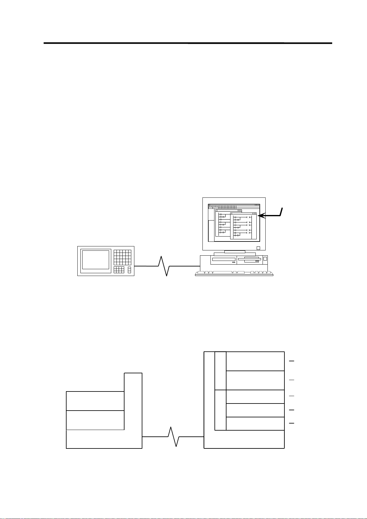
1.1.1 Development Environment Configuration
Most of the development works can be done by connecting the IBM PC/AT compatible machine and
a CNC unit by an RS-232C cable or RS-422 cable and by executing the tools on the personal
computer.
IBM PC/AT-compatible machine
(CD drive is required)
GX Developer
(GPPW)
CNC controller
System configuration using GX Developer
1.1.2 Software Configuration
PLC onbo ard
QnA simulator
CNC controller
RS-232C cable,
RS-422 cable
or Ethernet cable
RS-232C cable,
RS-422 cable
or E thernet cable
PLC development tool
C
s
for MELSEC
t
E
c
GX Developer
S
u
L
d
Data conversion
o
E
r
p
M
package for MELSEC
GX Converter
List output converter
S
s
t
A
c
D
u
L
d
o
E
r
p
M
PCNV6L
Comment converter
CLST6M
Ladder list converter
CLST6L
IBM PC/AT
Compatibl e machine
(1)
(2)
(3)
(4)
(5)
- 1 -
Page 11

1. PLC Development Environment Using GX Developer
1.1 Function
(1) GX Developer (PLC development software package for Windows)
GX Developer is a programming software package (model name: SW7D5C-GPPW) designed
for Mitsubishi Electric's MELSEC series programmable logic cont rollers. The conventional
function corresponding to MELDAS PLC development S/W (PLC4B) has been reinforced, and,
furthermore, that is a strong tool added the monitoring function by way of RS-232C. Note that
some functions specific to the "MELSEC series" may not be unavailable.
For MELDAS series ladder development, we recommend you to use GX Developer Version 4
(SW4D5C-GPPW) or later. For function details, refer to the operating manual supplied.
The DOS version "GPPQ" (SW2IVD/NX-GPPQ GPP function software package) of this
package is also usable. Refer to "Appendix3. Operation Method Using GPPQ" for details.
(2) GX Converter (Data conversion software package for Windows)
The GX Converter is a tool that carries out file conversion of GX Developer data files and the
following:
• Ladder list files and comment text files output by the CLIST6L
• Alarms and operator messages created by the text editor
• Data files of commercially available spreadsheet software, word processors and editors
This tool is add-on tool of the GX Developer, thus, start GX Converter from the GX Developer’s
menu.
This tool is a software package for MELSEC. GX Converter needs to be used with the versions
following GX Developer Version 3 (SW3D5C-GPPW). Refer to the enclosed Operating Manual
for function details.
The DOS version "CNVQ" (SW0IVD/NX-CNVQ data conversion software package) of this tool
can also be used. Refer to "Appendix 3. Operation Methods Using GPPQ" for details.
(3) PCNV6L (List output converter)
This tool outputs a MELDAS specification ladder printing image with cross information into the
text format from the GX Developer specification ladder list and comment data. Refer to the
instruction manual for function details.
This tool works on the DOS of Windows.
(4) CLST6M (Device comment converter)
This tool outputs the contact/coil comment data of a user PLC ladder developed using PLC4B
into the text format of the GX Developer specifications. The comment data developed using
PLC4B can be used with GX Developer by using GX Converter to further convert the
conversion results of this tool. Refer to the instruction manual for function details.
This tool works on the DOS of Windows.
(5) CLST6L (Ladder list converter)
This tool converts the user PLC ladder list data developed using PLC4B, and outputs the data
in a ladder list format. The user PLC ladder developed using PLC4B can be used with the GX
Developer by using the GX Converter to further convert the conversion results of this tool. Refer
to the instruction manual for function details.
This tool works on the DOS of Windows.
- 2 -
Page 12
1. PLC Development Environment Using GX Developer
1.1 Function
1.1.3 GX Developer Functions Supported by C64 Series
The GX Developer functions explained here are those supported by the C64 Series in the "off-line
functions" operated with the GX Developer independently and "on-line functions" carried out
connected to the CNC controller.
Refer to the enclosed Operating Manual for details of respective functions.
Refer to "Appendix 3. Operation Methods Using GPPQ" for the GPPQ-specific functions and
operations when the DOS version "GPPQ" (SW2IVD/NX-GPPQ GPP function software package) is
used.
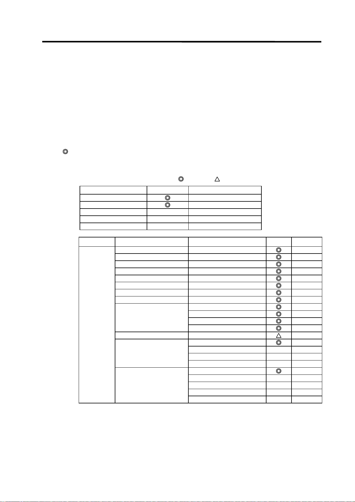
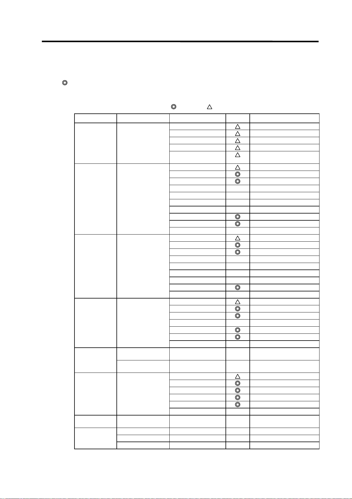
1.1.3.1 Function Support Conditions (general section)
The following shows a list of GX Developer outline functions supported by the C64 Series.
A
mark indicates functions that can be used by the C64 Series. An r mark indicates that the
function cannot be used because it is related to "MELSEC Series" characteristic functions. The
function details during on-line are described in the next section.
List of general section functions (1)
Program type Support Remarks
Ladder
List
SFC
MELSAP-L
Function block
U
U
U
Function Menu Sub menu Support Remarks
Project New project
Open project
Close project
Save
Save as
Delete project
Verify
Copy
Edit Data New
Copy
Delete
Rename
Change PLC type
Import file Import from GPPQ format file
Import from GPPA format file
Import from FXGP[WIN] format file
Import from FXGP[DOS] format file
Export file Export to GPPQ format files
Export to GPPA format files
Export to FXGP[WIN] format file
Export to FXGP[DOS] format file
Export to TEXT ,CSV format file
: Possible,
: Limitedly possible, U : Not possible
U
U
U
U
U
U
Fixed Q4A
- 3 -
Page 13
1. PLC Development Environment Using GX Developer
1.1 Function
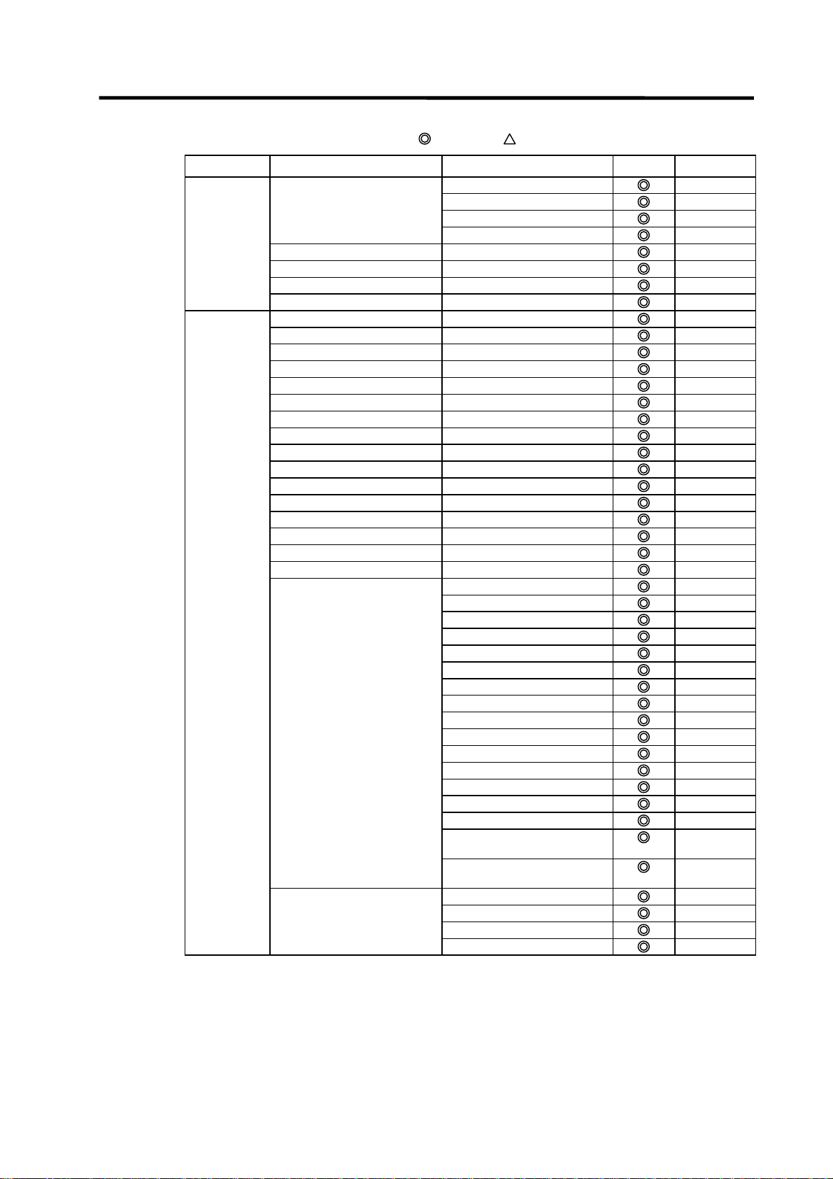
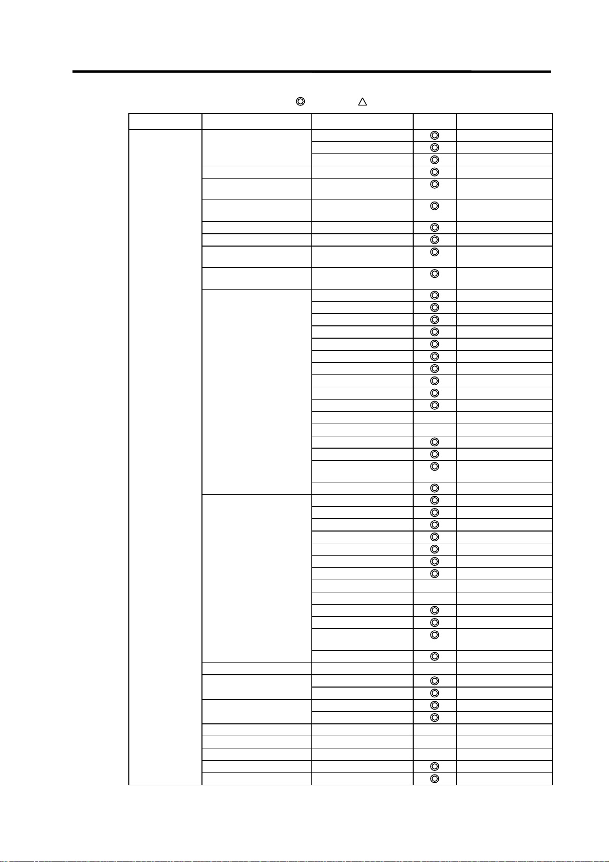
List of general section functions (2)
Function Menu Sub menu Support Remarks
(Project) Macro Registration macros
Macro utilize
Delete macros
Macro reference path
Printer setup
Print
Start new GX Developer session
Exit GX Developer
Edit Undo
Restore after ladder conversion
Cut
Copy
Paste
Insert line
Delete line
Insert row
Delete row
Insert NOP batch
Delete NOP batch
Draw line
Delete line
Change TC setting
Read mode
Write mode
Ladder symbol Open contact
Close contact
Open branch
Close branch
Coil
Application instruction
Vertical line
Horizontal line
Delete vertical line
Delete horizontal line
Rising pulse
Falling pulse
Rising pulse open branch
Falling pulse close branch
Invert operation results
Convert operation results to
Convert operation results to
Documentation Comment
Statement
Note
Statement/Note block edit
: Possible,
rising pulse
falling pulse
: Limitedly possible, U : Not possible
- 4 -
Page 14
1. PLC Development Environment Using GX Developer
1.1 Function
List of general section functions (3)
Function Menu Sub menu Support Remarks
Find/Replace Find device
Find instruction
Find step no.
Find character string
Find contact or coil
Replace device
Replace instruction
Change open/close contact
Replace character string
Change module start address
Replace statement/note type
Cross reference list
List of used devices
Convert Convert
Convert (All programs being
Convert (Online change)
View Comment
Online
Diagnostics PLC diagnostics
edited)
Statement
Note
Alias
Macro instruction format display
Comment format 4*8 characters
3*5 characters
Alias format display
Replace device name and
Toolbar
Status bar
Zoom 50%
75%
100%
150%
Auto
Project data list Specify
Instruction list
Elapsed time
Refer to "List of on-line section
functions"
Network diagnostics
Ethernet diagnostics
CC-Link diagnostics
System monitor
: Possible,
display
Arrange with device and display
Refer to "List of on-line section
functions"
: Limitedly possible, U : Not possible
U
U
U
U
U
U
- 5 -
Page 15
1. PLC Development Environment Using GX Developer
1.1 Function
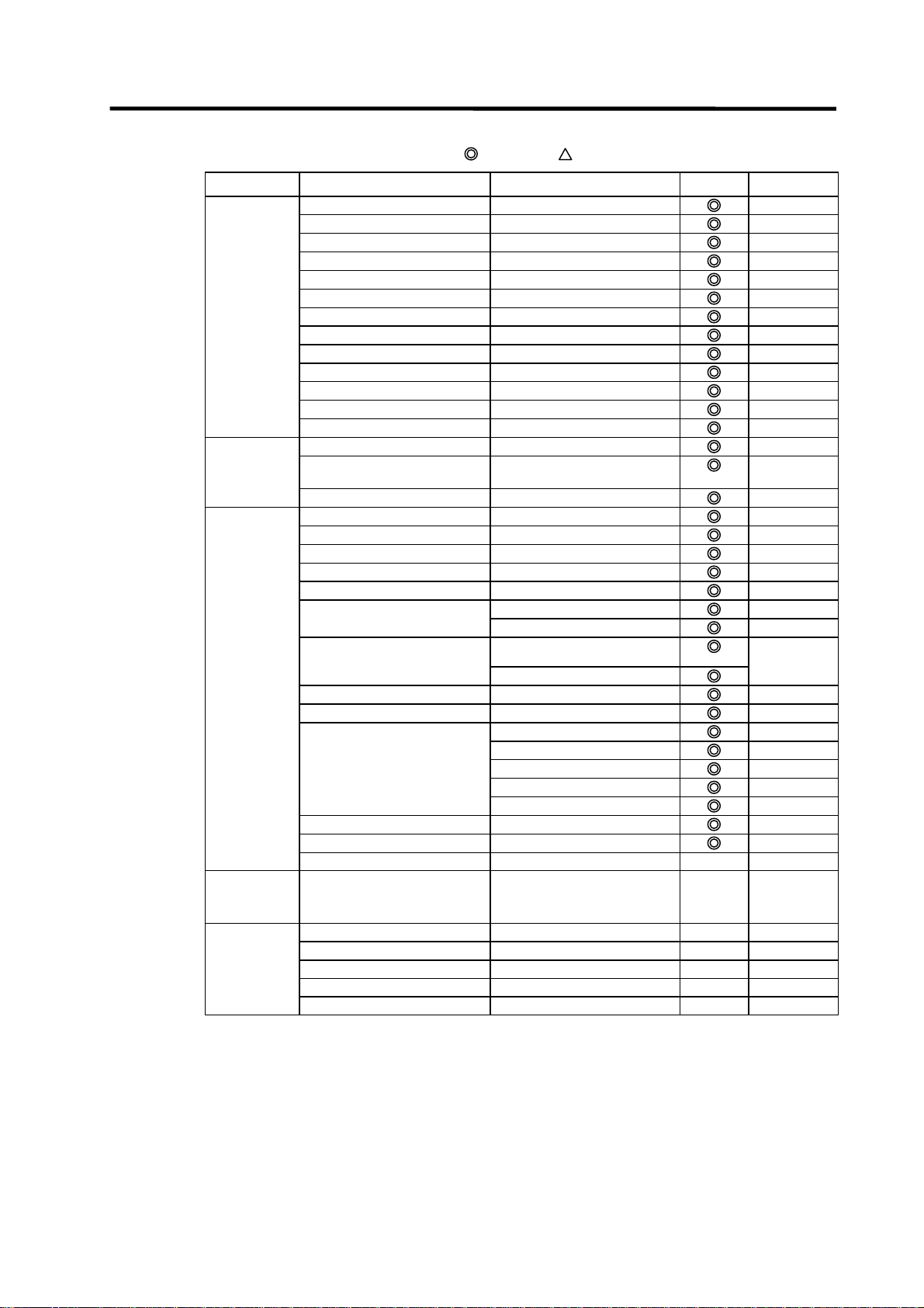
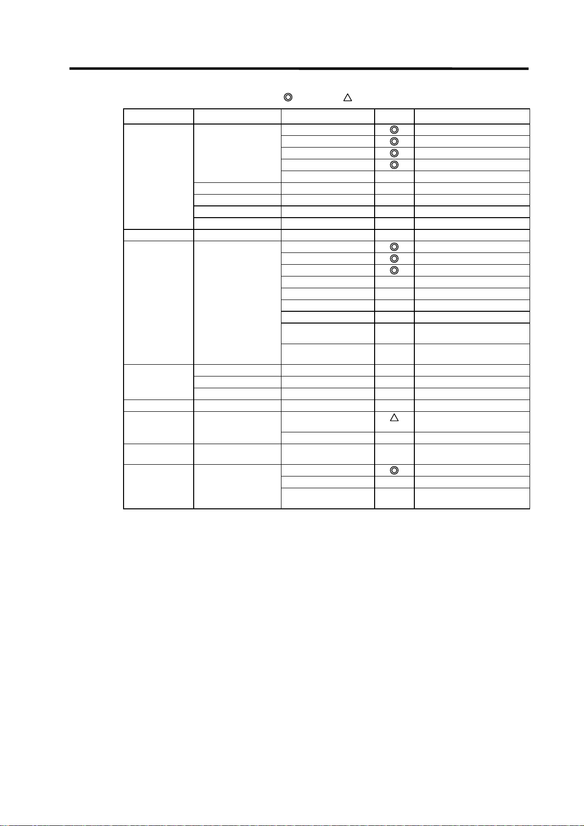
List of general section functions (4)
Function Menu Sub menu Support Remarks
Tools Check program
Merge data
Check parameter
Transfer ROM Read
Write
Verify
Write to file
Delete unused comments
Clear all parameters
IC memory card Read IC memory card
Write IC memory card
Read image data
Write image data
Start ladder logic test
Set TEL data Connection
Disconnection
TEL data
AT command
Call book
Intelligent function utility Utility list
Customize keys
Options
Create start-up setting file
Window Cascade
Tile vertically
Tile horizontally
Arrange icons
Help PLC error
Special relay/register
Key operation list
Product information
Connect to MELFANSweb
: Possible,
: Limitedly possible, U : Not possible
U
U
U
U
U
U
U
U
U
U
U
U
U
U
U
Partially
impossible
U
U
- 6 -
Page 16
1. PLC Development Environment Using GX Developer
1.1 Function
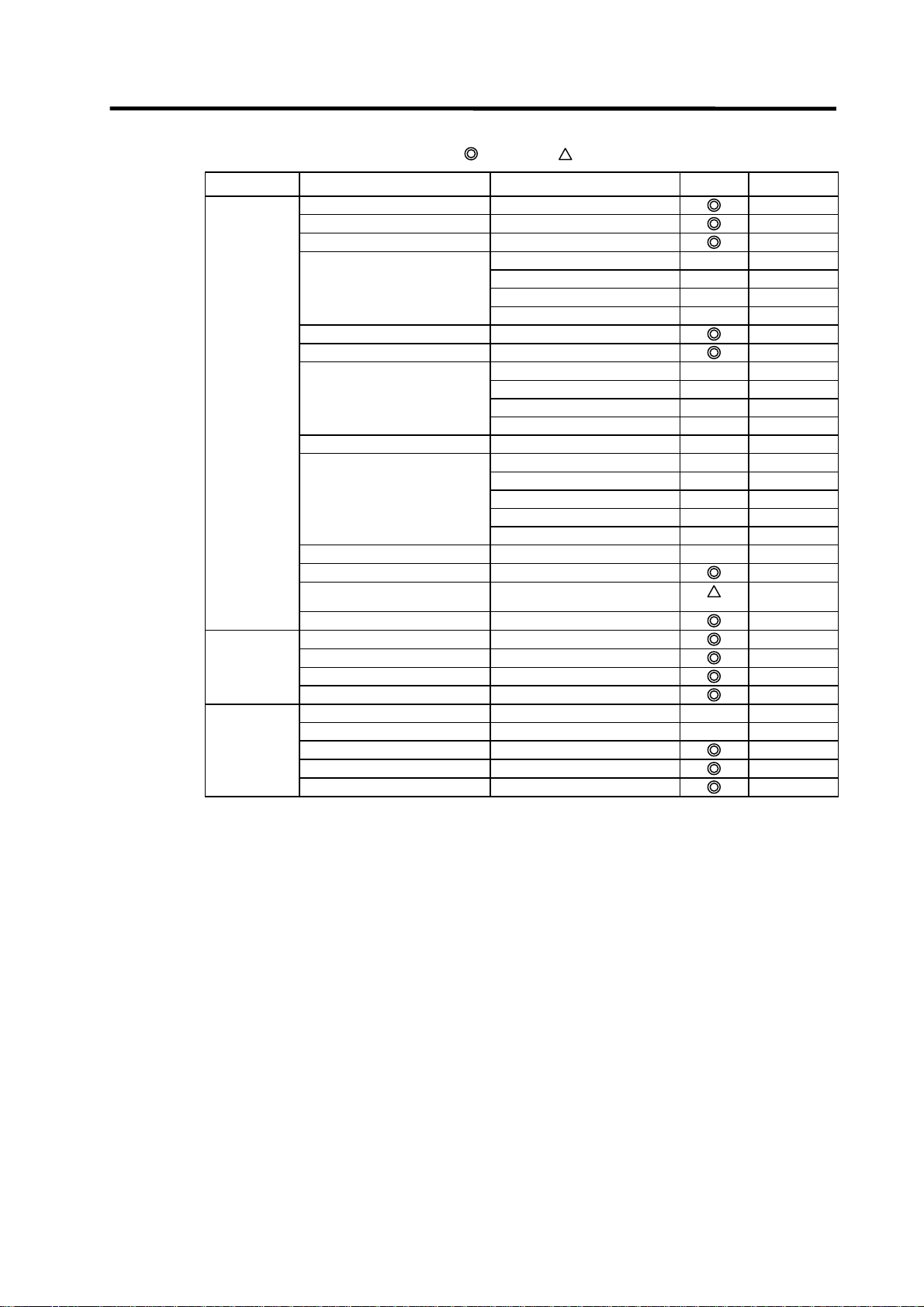
1.1.3.2 Function Support Conditions (on-line section)
The following shows a list of GX Developer on-line functions supported by the C64 Series.
A
mark indicates functions that can currently be used by the C64 Series. An r mark indicates
that the function cannot be used because it is related to "MELSEC Series" characteristic functions.
List of on-line section functions (1)
Menu Sub me nu Detailed function Support Remarks
Transfer setup PC side I/F
PLC side I/F
Other station
Network route
Co-existence network
Read from PLC Target memory
Title
File selection
Device data
Program
Common
Local
Refresh view
Free space volume
Create title
Write to PLC Target memory
Title
File selection
Device data
Program
Common
Local
Free space volume
Create title
Verify with PLC Target memory
Title
File selection
Program
Refresh view
Free space volume
Create title
Write to PLC
[Flash ROM]
Write to PLC
Delete PLC data Target memory
Title
File selection
Refresh view
Free space volume
Create title
Change PLC data
attributes
PLC user data Read PLC user data
Write PLC user data
Delete PLC user data
Write the program
memory to ROM
[Flash ROM]
: Possible,
route
: Limitedly possible, U : Not possible
Only for QnACPU
Only for internal memory
U
U
U
U
U
Only for internal memory
U
U
U
U
U
Only for internal memory
U
U
U
U
Only for internal memory
U
U
U
U
U
- 7 -
Page 17
1. PLC Development Environment Using GX Developer
1.1 Function
List of on-line section functions (2)
Menu Sub menu Detailed function Support Remarks
Monitor Monitor mode ON/OFF state
Scan time
PLC status
Monitor [Write mode]
Start monitor
[All windows]
Stop monitor
[All windows]
Start monitor
Stop monitor
Change current value
monitor [Decimal]
Change current value
monitor [Hexadecimal]
Device batch Device
Connect
Coil
Setting value
Current value
Monitor format : Bit & word
Monitor format : Bit
Monitor format : word
Display : 16bit integer
Display : 32bit integer
Display : Real number
Display : ASCII character
Value : DEC
Value : HEX
T/C set value Reference
Device test
Entry data monitor Device
ON/OFF/Current
Setting value
Connect
Coil
Display : 16bit integer
Display : 32bit integer
Display : Real number
Display : ASCII character
Value : DEC
Value : HEX
T/C setting value, Local
Device test
Buffer memory batch
Monitor condition setup Device
Step No.
Monitor stop condition setup Device
Step No.
Program monitor list
Interrupt program monitor list
Scan time measurement
Entry ladder monitor
Delete all entry ladder
: Possible,
program
label Reference program
: Limitedly possible, U : Not possible
U
U
U
U
U
U
U
U
- 8 -
Page 18
1. PLC Development Environment Using GX Developer
1.1 Function
List of on-line section functions (3)
Menu Sub me nu Detailed function Support Remarks
Debug Device test FORCE ON
FORCE OFF
Toggle force
Device
Buffer memory U
Debug
Skip execution
Partial execution
Step execution
Trace
Remote operation PLC status
RUN
STOP
PAUSE
Latch clear
STEP-RUN
Reset
Operation during RUN,
Specify execution
Keyword setup Register
Delete
Disable
Clear PLC memory
Format PLC
memory
Format
Arrange PLC
memory
Set time Date / time
Day of week
Specify execution
Target memory
: Possible,
STEP-RUN
destination
destination
: Limitedly possible, U : Not possible
U
U
U
U
U
U
U
U
U
U
U
U
U
U
U
For only internal RAM
U
U
U
U
- 9 -
Page 19
1. PLC Development Environment Using GX Developer
1.2 Setup
1.2 Setup
1.2.1 Installing the Tools
In the C64 Series PLC development environment, it is assumed that the various tools are u se d on
an IBM PC/AT compatible machine. Prepare each tool so that it is IBM PC/AT compatible machine.
Refer to the enclosed Operating Manual for the setup and start procedures of each tool.
1.2.2 Connecting the Serial Cable
As for the serial port connected with the CNC, refer to the MELDAS C6/C64/C64T Connection and
Maintenance Manual (BNP-B2255).
(1) RS-232C connection
Between the IBM PC/AT compatible machine that uses GX Developer and the CNC controller,
use an RS-232C serial cable equivalent to the one shown below in the RS-232C connection
diagram.
(Note) The cables given in the connection diagrams of the GX Developer Operating Manual
cannot be used.
As for the CNC side, setting for GPPW communication is not necessary.
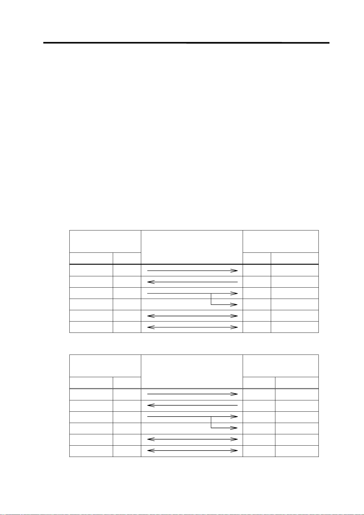
(a) When connecting with C64 controller directly
NC side (TERMINAL)
Personal computer side
Cable connection and
(20-pin half-pitch)
(9-pin D-SUB)
signal direction
Signal name Pin No.
Pin No. Signal name
SD 6 2 RD
RD 16 3 SD
ER(DTR) 18 6 DR(DSR)
8 CS(CTS)
GND 1 1 GND
GND 11 5 GND
(b) When connecting with C64 controller using the intermediate cable dedicated to C64
NC side (TERMINAL)
Personal computer side
Cable connection and
(25-pin D-SUB)
(9-pin D-SUB)
signal direction
Signal name Pin No.
Pin No. Signal name
SD 2 2 RD
RD 3 3 SD
ER(DTR) 20 6 DR(DSR)
8 CS(CTS)
GND 1 1 GND
GND 7 5 GND
- 10 -
Page 20

1. PLC Development Environment Using GX Developer
1.2 Setup
(2) RS-422 connection
MELSEC-dedicated cable can be used to connect with C64 controller.
Refer to the GX Developer Operating Manual for details.
(3) Ethernet connection
For the connection using Ethernet, the Ethernet card (FCU6-EX875) must be mounted to the
extension slot on the control unit.
Connect the Ethernet cable to the modular jack on the Ethernet card.
1.3 Developing PLC Programs
1.3.1 Precautions before Development
Pay careful attention to the following items before developing PLC programs using the GX
Developer.
(1) PC type selection
The PLC type must be set when newly creating programs, etc. Select the following CPU type when
requested to select the PLC type with the GX Developer. An error will occur during transfer of the
PLC program to the CNC if another PLC type is selected.
Select "Q4A" for CPU type.
(2) Device setting
Do not set the devices when developing the PLC program for the CNC. Develop the program with
the device settings (No. of points, etc.) left at their default values applied when GX Developer was
started. The PLC program cannot be transferred to the CNC normally when it is developed with
settings other than the default values.
Do not set the devices.
(3) PLC commands
MELSEC-specific PLC commands cannot be used in the PLC program development for the CNC.
Refer to “6.1 Command List Table” and confirm the useable commands.
The format, etc., are changed with some commands. Refer to "1.5 PLC4B PLC Development
Environment and Differences" for details.
MELSEC-specific PLC commands cannot be used.
(4) Label at the beginning of ladder program
In a MELDAS PLC program, a processing unit is differentiated by specifying a reserved label
number at the beginning of processing. There are the following different processing units.
P251, P360 to 368 : PLC high-speed processing program starting label
P252, P370 to 378 : PLC main processing program starting label
Even if only the PLC main processing is to be performed, do not omit but describe the above label
at the beginning of a PLC program. Unless the label is described, normal RUN cannot be performed.
Specify a label at the beginning of a PLC program.
- 11 -
Page 21
1. PLC Development Environment Using GX Developer
1.3 Developing PLC Programs
(5) Statements and notes
GX Developer allows a PLC program to be commented (with interlinear statements and notes).
They are available in two types: integrated and peripheral.
Integrated type : Can be downloaded together with a ladder program to the CNC
controller.
Peripheral type : Cannot be downloaded.
The integrated type cannot be used with the C64 series. If it is used, a PLC program cannot be
transferred to the CNC properly.
Do not use integrated type interlinear statements and notes.
Create the message data as the integrated type statement.
(6) File name
Inside the C64 series, PLC-related data are controlled and stored in the following categories.
Therefore, they are also developed in the same categories.
!
CAUTION
!
If the data transferred does not follow the following file name rule, the NC will
mistake it for another data, resulting in unexpected operation, e.g. PLC
program erasure.
File name rule
M1
(Note) File name that is not permitted.
xxxx.
When data is transferred by GX Developer, its data type is distinguished by the file name.
An extension indicates a file type, and the first two characters denote a data type and a language
type.
File name can be specified within eight characters including data classification and language
classification freely with the exception of the extension.
The following characters at the head of file name are reserved for CNC side.
Do not use the file name of these characters combination.
Data classification
Language classification
WPG or WCD
Extensions .... Automatically attached with the GX Developer
(expresses file classification)
Random file name .... User free designation
Dataclassification and languag eclassification
(M1:Message 1st languag e )
: "M", "C", "H" (alphabet)
: "0" to "9" (number)
.... userfixed
designation
- 12 -
Page 22
1. PLC Development Environment Using GX Developer
1.3 Developing PLC Programs
List of PLC-related data
Related data classification
12 PLC program (ladder)
PLC program comment
3 Message 1st language M1xxxx.WPG Message 1st language data such
4 Message 2nd language M2xxxx.WPG Same as above
(a) PLC program (ladder)
• PLC program developed using GX Developer.
• Only one file can be stored in the NC.
(b) PLC program comment
• Program comment for GX Developer display
• Only one file can be stored in the NC with the same file name as the PLC program.
• A device comment (32 characters) and a device name (10 characters) can be defined for each
device.
• Stored mainly when it is read to GX Developer and used as a comment.
(c) Message 1st language and (4) 2nd language
• Alarm message/operator message/PLC switch/comment message data.
• One 1st language file and one 2nd language file can be stored in the NC.
• The messages can be handled and edited as "integrated type interlinear statements" by GX
Developer.
• The maximum message length and the number of messages can be specified for each
message type.
1.3.2 Creating a New Program
Create a new program using GX Developer.
Refer to the GX Developer's operation manual for details of usage.
File name
(GX Developer)
zzzzzz.WPG
zzzzzz.WCD
Remarks
PLC ladder code
Comment data for GX Developer
as alarm messages/
operator messages/
PLC switches/
tool registration comment/
load meter comment
(2nd language data)
- 13 -
Page 23
1. PLC Development Environment Using GX Developer
1.3 Developing PLC Programs
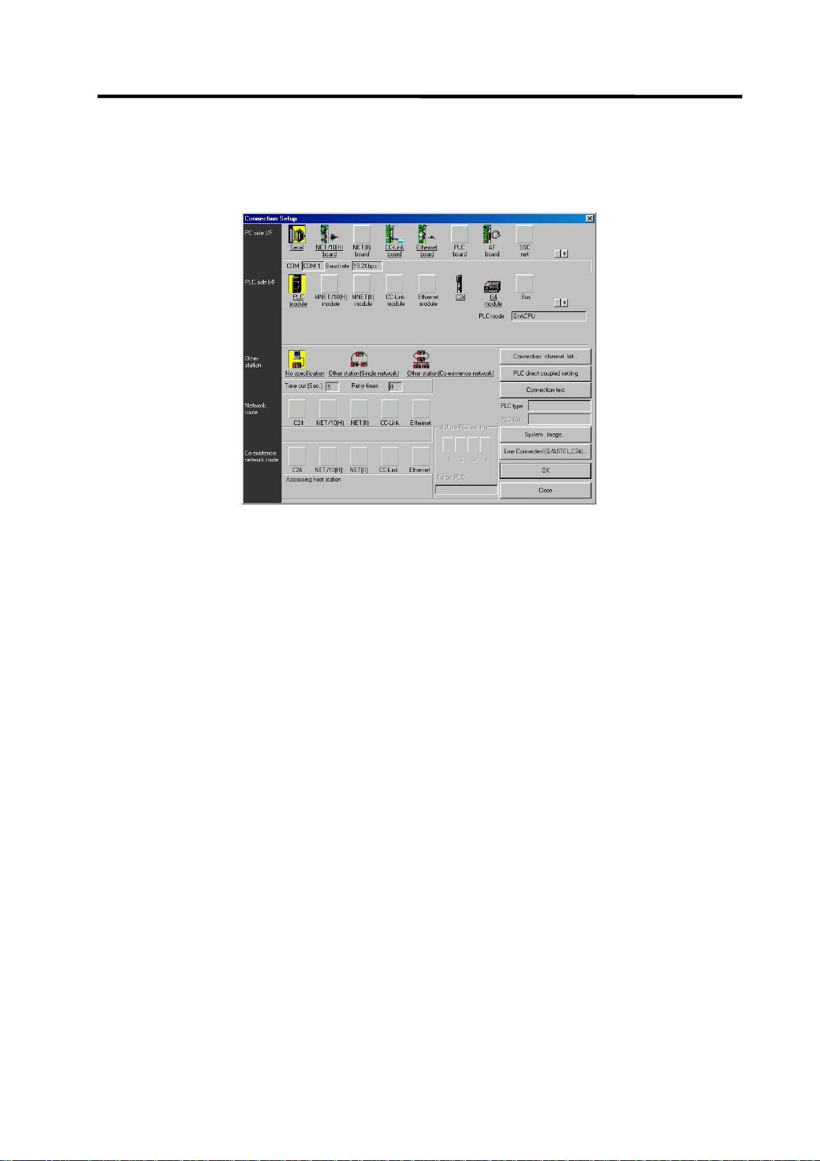
1.3.3 Specifying the Connection Target
You must specify the connection target before performing on-line operations from GX Developer to
the CNC.
(1) Operation procedure
Perform the following operation from GX Developer to start the setting screen.
[Online] → [Transfer setup]
Set only the following items. Leave the other items unchanged from the initial values.
(a) Setting for serial connection (RS-232C or RS-422)
• Personal computer side I/F : Serial
Serial port name COM1 or COM2
Baud rate 19.2Kbps
• PLC side IF : CPU unit
(b) Setting example for Ethernet connection
• Personal computer side I/F : Ethernet
Network No. 1
Station No. 1
• PLC side I/F : Ethernet unit
Network No. 1
Station No. 2
IP address (Address set by NC parameter)
Routing method Automatic conversion method
• CNC side IP address setting
#1926 IP address 192.182.1.2
#1927 Subnet mask 255.255.255.0
#1928 Gateway address 192.182.1.254
#1929 Port number 64758
# No. Parameter name Setting example
The local station’s IP address is set for the NC side.
The IP address set here is shared with the other Ethernet communication functions (GOT
connection, etc.).
(Note) The setting example above is for when the GX Developer is connected to the CNC.
To connect the GX Developer to the Ethernet or multiple hierarchical network of
MELSECNET/10, setting values will differ.
- 14 -
Page 24
1. PLC Development Environment Using GX Developer
1.3 Developing PLC Programs
• Setting the GX Developer Connection Destination
These parameters are used to set the GX Developer connection method. These
parameters are included in the GX Developer project data.
- 15 -
Page 25
1. PLC Development Environment Using GX Developer
1.3 Developing PLC Programs
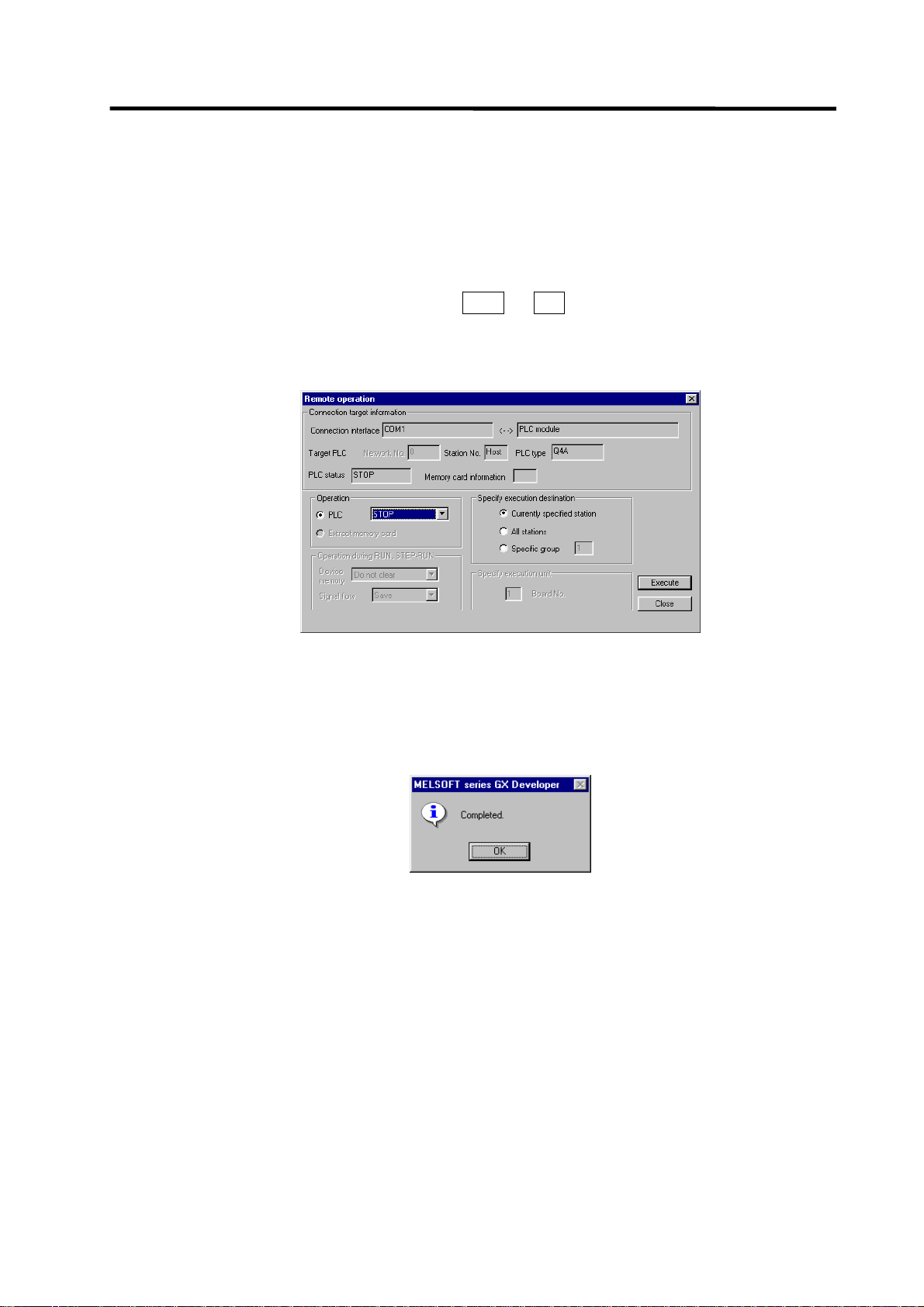
1.3.4 Starting/Stopping the PLC of the CNC
Before writing a ladder program, you must stop the PLC of the CNC.
(1) Operation procedure
Perform the following operation from GX Developer to start the operation screen.
[Online] → [Remote operation] or Alt + 6
On the following screen, set "STOP" or "RUN" in the [PLC] part under [Operation] and click
[Execute]. The current status is displayed in [PLC status] under [Connection target information].
(Note) The operation other than "RUN" or "STOP" can not be performed.
The operation is completed when the following dialog appears. Click [OK]. The status after
completion appears in [PLC status] on the remote operation screen displayed behind. If the status
does not change, check whether an alarm is displayed or not on the CNC side.
- 16 -
Page 26
1. PLC Development Environment Using GX Developer
1.3 Developing PLC Programs
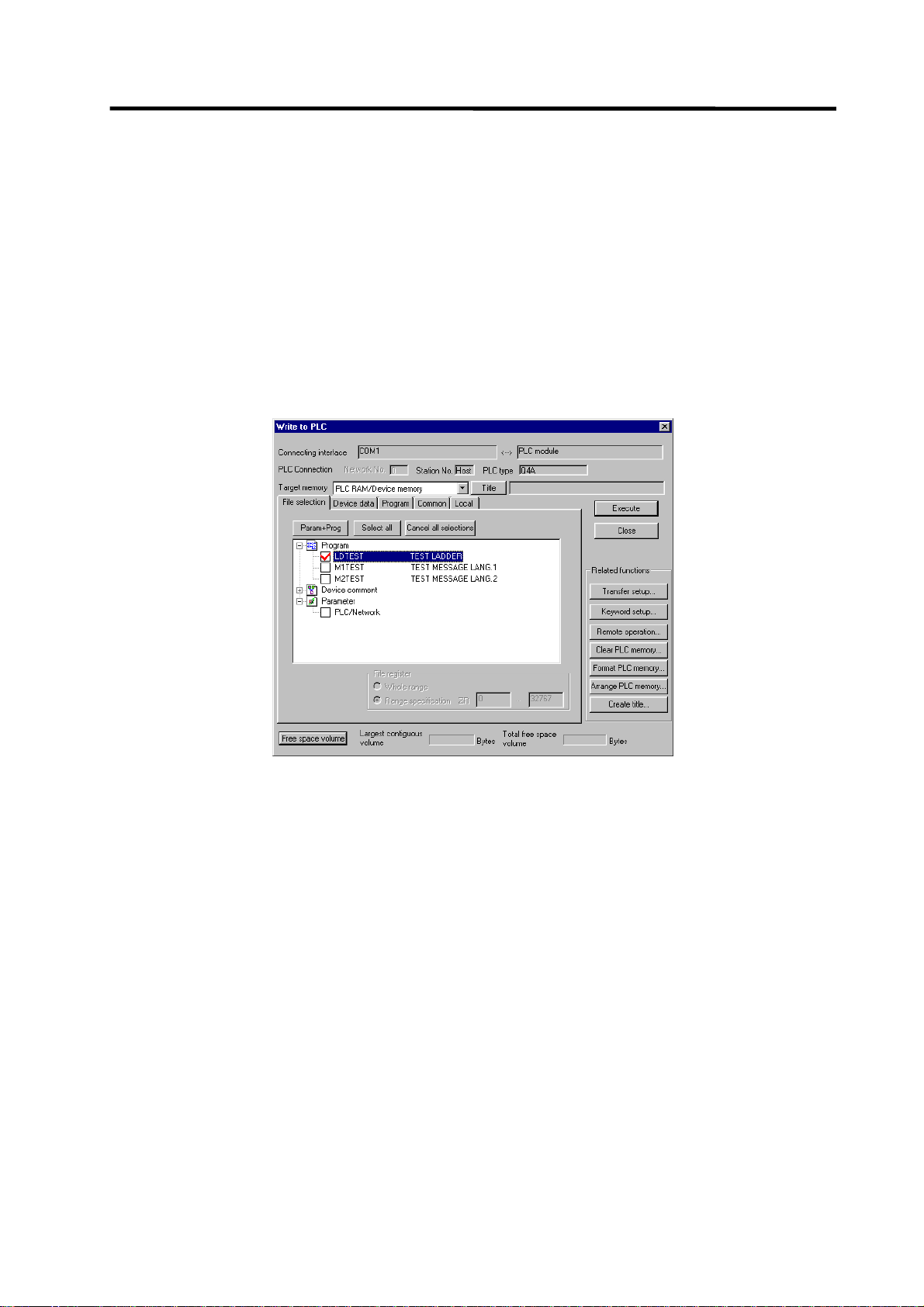
1.3.5 Writing the PLC Program to the CNC
The following indicates how to write ladders from GX Developer to the CNC (especially the
restrictions and C64 series-specific operations).
(1) Operation procedure
Perform the following operation from GX Developer to start the operation screen.
[Online] → [Write to PLC]
On the following screen, choose the ladder file to be written from the [File selection] tab and click
[Execute].
You can command RUN/STOP of the PLC using [Remote operation] under [Related functions].
(Note) As [Target memory], only [PLC RAM/Device memory] is valid.
Do not set the other tabs ([Device data], [Program], [Common], [Local]) than [File
selection].
- 17 -
Page 27
1. PLC Development Environment Using GX Developer
1.3 Developing PLC Programs
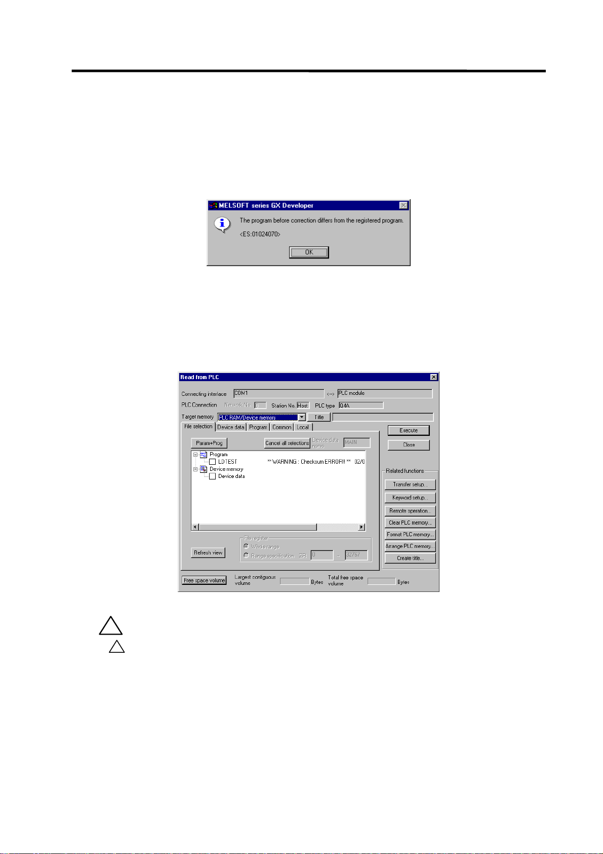
(2) Operation to be performed at write error
As soon as a ladder is written from GX Developer to the CNC, the CNC converts it into the CNCspecific ladder machine code. A conversion error occurs if any of the devices and command formats
not supported by the C64 series is used.
At a conversion error, the CNC side ladder machine code is converted into the [NOP code], the
ladder up to the last step is transferred, and the following dialog is then displayed on the GX
Developer screen.
When the file that resulted in a conversion error is displayed with the [File selection] tab of the
[Read from PLC] screen, the following warning appears in the title field.
“∗∗ WARNING Checksum ERROR!! ∗∗”
If you execute RUN the PLC as-is, an alarm occurs on the CNC side and the PLC does not RUN.
!
CAUTION
!
Do not read a sequence program on which a conversion error occurred into
the GX Developer.
The file may include unexpected contents to result an illegal operation.
- 18 -
Page 28
1. PLC Development Environment Using GX Developer
1.3 Developing PLC Programs
(3) How to confirm the error step number
At a conversion error, error information is stored to the special registers as below. Devicemonitoring these registers enables to find the error position.
SD30 : Error step No. where the error occurred.
SD31 : Cause of the error.
The error No. which occurred while writing from GX Developer to C64
SD31 value Cause of error
1 Command format error.
2 File already exists.
3 File to be read is not found.
4 Object code error.
5 File can not be opened.
6 File name is too long.
7 File name is illegal.
9 This is not a ladder or a message file.
10 Ladder code has been already changed.
20 Device No. exceeds the specification range.
21 Search was failed.
22 Device No. is illegal.
23 There is an error in the conversion table data.
24 Conversion can not be performed.
(Already converted with M500.)
25 Attribute code is illegal.
101 Warning : Device can not be converted.
102 Some of the designated digits can not be used in the ladder
sub-routine.
103 Designated index can not be used in the ladder sub-routine.
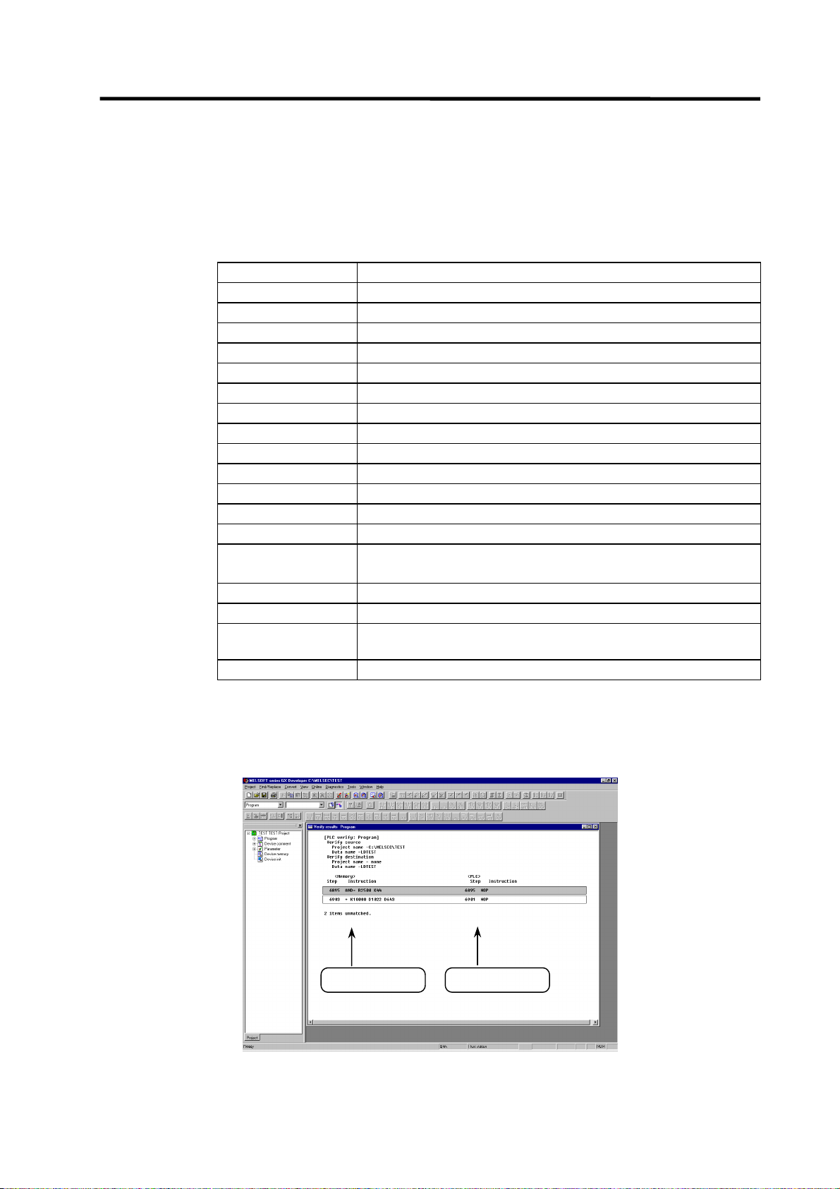
The [Verify with PLC] function can be used to confirm the error step. Executing verification with PLC
displays mismatches as in the following example. For details of the [Verify with PLC] function, refer
to "1.3.7 Verifying the PLC Programs".
<Memory> indicates the GX Developer side, and <PLC> the CNC side.
GX Developer side
CNC controller side
- 19 -
Page 29
1. PLC Development Environment Using GX Developer
1.3 Developing PLC Programs
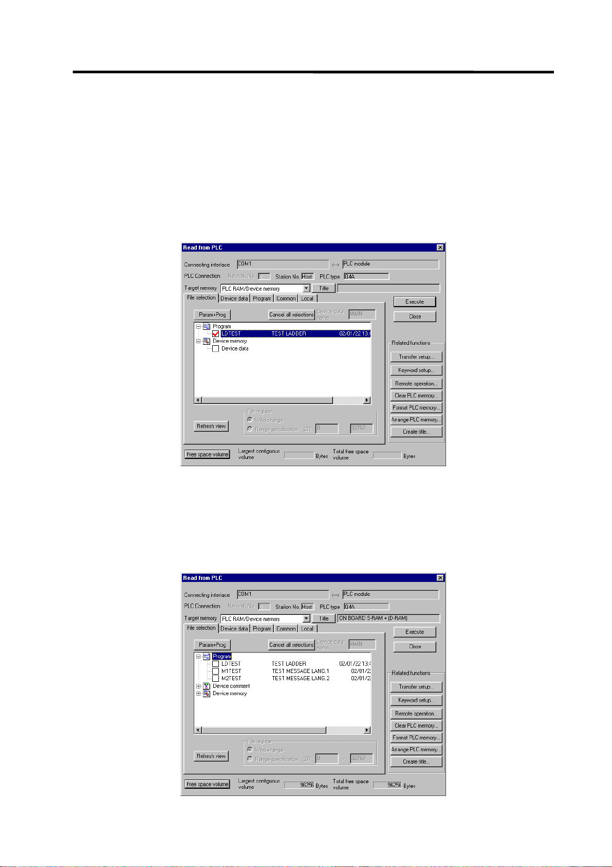
1.3.6 Reading the PLC Program from the CNC
The following indicates how to read a ladder from the CNC to GX Developer.
(1) Operation procedure
Perform the following operation from GX Developer to start the operation screen.
[Online] → [Read from PLC]
On the following screen, choose the ladder file to be read from the [File selection] tab, and click
[Execute].
(Note) As [Target memory], the fitted memory is valid.
Do not set the other tabs ([Device data], [Program], [Common], [Local]) than [File
selection].
The [Read from PLC] screen can also be used as a CNC side file listing function. Move the scroll
bar of the [File selection] tab to the right to display the write date and size of each file. Click [Free
space volume] to display the free area of the target memory.
- 20 -
Page 30
1. PLC Development Environment Using GX Developer
1.3 Developing PLC Programs
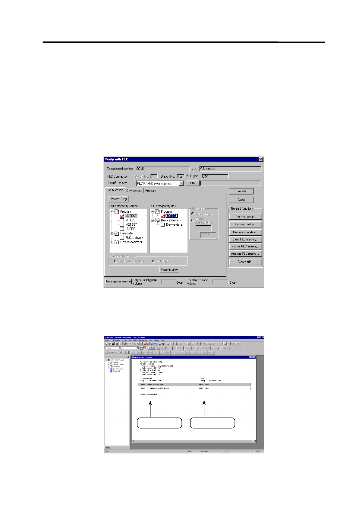
1.3.7 Verifying the PLC Programs
The following indicates how to verify ladders between the CNC and GX Developer.
(1) Operation procedure
Perform the following operation from GX Developer to start the operation screen.
[Online] → [Verify with PLC]
On the following screen, choose the ladder files to be verified with the [File selection] tab, and click
[Execute].
[Verify source] : GX Developer side [Verify dest] : CNC side
(Note) As [Target memory], the fitted memory is valid.
Do not set the other tab ([Program], [Device data]) than [File selection].
If verification mismatches occur, the following mismatch screen appears. Double-click the mismatch
to display the corresponding part of the GX Developer side file.
GX Developer side
CNC controller side
- 21 -
Page 31

1. PLC Development Environment Using GX Developer
1.3 Developing PLC Programs
1.3.8 Monitoring the PLC Program
There are no MELDAS-specific operations to monitor a PLC program. Refer to the GX Developer
operating manual for the operation methods. For usable functions, refer to "1.1.3.2 Function Support
Conditions (on-line section)". This section explains the operation procedure outline and precautions.
(1) Operation procedure
Perform the following operation from GX Developer to start monitoring.
(a) Display the ladder program to be monitored and move to the circuit part to be monitored.
(b) Perform the following operation to start monitoring.
[Online] → [Monitor] → [Monitor mode] or F3
(c) Perform the following operation to stop monitoring.
[Online] → [Monitor] → [Stop monitor] or Alt + F3
(Note) If the ladder program being run by the CNC diff ers from the one being displayed on GX
Developer, monitoring will not result in an error but will continue
.
- 22 -
Page 32

1. PLC Development Environment Using GX Developer
1.3 Developing PLC Programs
1.3.9 Diverting the PLC program that was developed using PLC4B
(Note) PLC4B and LIST4B can not be used with C64. This section describes the method to use
the ladder data on the C64 series system, however, the ladder data here must be created
with PLC4B of the former-model CNC.
(1) Development procedure
IBM PC/A T comp atible mac hine
Creation
PLC4B/LIST4B
LIST4B
outpu t ladde r
list
zzzz.TX T
Ladder list for
CNC
zzzz. T X T
Ladder data
for CNC
zzzz.WPG
Ladder list conversion
CLST6L
List to ladder conversion
GX Converter
Editing (transfer)
GX Developer
(Note)
CNC controller
(a) Creation
The PLC program created for the old model is output in a list format.
(b) Conversion
Using CLST6L (ladder list converter), the output program is converted into a PLC program (list
format). Using GX Converter (data conversion software package), the list format program is
converted into the GX Developer data.
(c) Editing/transfer
The resultant program can be handled like a newly created PLC program.
Device
comment s
for CNC
zzzz. W CD
RS-232C, etc.
Messages
for CNC
M1xxx.WPG
- 23 -
Page 33

1. PLC Development Environment Using GX Developer
1.3 Developing PLC Programs
(2) Starting GX Converter and specifying the file to be converted
Perform the following operation from GX Developer to start GX Converter (read).
[Project] → [Import file] → [Import to TEXT ,CSV format file]
On the following screen, specify the file to be converted (LDTEST.TXT) and click [OK].
(3) Conversion format setting
Set the conversion format on the following data conversion wizard screen.
(a) Data conversion wizard 1/4
Choose [Original Data Type]-[Delimited] and [Data Type]-[List], and click [Next>].
- 24 -
Page 34

1. PLC Development Environment Using GX Developer
(b) Data conversion wizard 2/4
Choose [Delimiters]-[Tab] and click [Next>].
1.3 Developing PLC Programs
(c) Data conversion wizard 3/4
Choose to highlight the [Instr] column part in the [Data Preview] list and choose [Column Data
Format]-[Instruction].
- 25 -
Page 35

1. PLC Development Environment Using GX Developer
(d) Data conversion wizard 3/4
Further, choose to highlight the Argument column part in the [Data Preview] list and choose
[Column Data Format]-[I/O(Device)]. Click [Next>].
1.3 Developing PLC Programs
(e) Data conversion wizard 4/4
Set the program name used on GX Developer at [Data name] column and a ladder annotation
at [Title] column, and click [Finish].
(f) Completion
The setting is complete when the following completed dialog appears after the converting dialog.
Click [OK].
- 26 -
Page 36

1. PLC Development Environment Using GX Developer
1.4 Creating PLC-related Data
1.4 Creating PLC Message Data
This chapter explains a procedure for developing PLC-related data such as ala rm me ssages,
operator messages, and PLC switches.
1.4.1 Development Procedure
There are the following two methods as a general development procedure of message data.
1) Making conversion into GX Developer data using a general text editor or spreadsheet tool and
data conversion package.
(When there is a large volume of message data and you want to control them with a
commercially available tool, for example)
2) Entering messages directly from GX Developer
(When there is a small volume of message data or when addition or correction is to be made, for
example)
IBM PC/AT compatible machine
Creation
Spreadsheet tool
Text editor
CNC
message
M1 xxx.TXT
CNC
message
M1xxx.WPG
Conversion
GX Converter
Transfer (edit)
GX Developer
CNC controller
RS-232C, etc.
CNC device
commen t
zzzz.WCD
CNC
ladder
zzzz. W PG
- 27 -
Page 37

1. PLC Development Environment Using GX Developer
1.4 Creating PLC-related Data
(1) Using a general text editor
(a) Creation
The message data is described using a general text editor. The description method and format
will be described later.
(b) Conversion
The conversion from text data to GX Developer data is carried out using the "GX Converter
(data conversion software package)".
(c) Transfer
With the GX Developer, the message data is handled as a PLC program interlinear comment,
and can also be edited.
The message data is transferred to the CNC controller using the GX Developer, in the same
manner as the ladder program.
(2) Entering messages directly from GX Developer
(a) Creation
The message data is described directly from GX Developer. The message data is handled as a
PLC program interlinear comment by GX Developer. The description method and format will be
described later.
(b) Transfer
The message data is transferred from GX Developer to the CNC in the same manner as the
ladder program.
- 28 -
Page 38

1. PLC Development Environment Using GX Developer
1.4 Creating PLC-related Data
1.4.2 Message Data Description Method
The message data can be described as text data by a general text editor and also by commercially
available spreadsheet software in addition to the direct input with GX Developer.
(1) Description Format
Message data is classified into setting areas to store the setting for each message and message
areas to store message data. It is described in the following respective description format.
(a) Setting area
The message length and No. of messages are set for each message in the setting area. The
message data region secured by the CNC can be adjusted to the most efficient status using
these settings. The respective maximum values are set if nothing is set. (Refer to "(4)
Precautions" for the maximum values.)
(b) Message area
The message area is described using the following description format.
The description format cannot be abbreviated. Comma(,) and [CR] must be described, even the
message character string is blank.
Message classification Description format
Alarm message ;A, index No., data register No., message character string [CR]
Operator message ;O, index No., data register No., message character string [CR]
PLC switch ;P, switch No. message character string [CR]
Comment message ;M, device, device No., message character string [CR]
Message classification
code
Index No.
Switch No.
Data register No.
Device
Device No.
Message character string
Semicolon( ; )
Comma( , )
[CR]
;$, message classification code
A:Alarm message O:Operator message
P:PLC switch M:Comment message
: A one-byte alphabetic character expressing each message
classification
: One-byte number (0 to No. of messages in the setting area - 1)
: One-byte number (0 to No. of messages in the setting area - 1)
: One-byte number
: One-byte number (1 or 2)
: One-byte number (0 to 10)
: One-byte alphanumeric character, shift JIS Code 1 character,
No. of characters in the setting area message length.
Semicolons, commas, spaces and tabs can also be used. Note
that the tab at the head of the message character string is
ignored.
: Message data identification code
: Separator between each description (a comma only is used to
leave a message character string blank)
: Line feed code, (CR/LF) or (LF).
, maximum message length, No. of messages [CR]
- 29 -
Page 39

1. PLC Development Environment Using GX Developer
1.4 Creating PLC-related Data
(2) Description Method
The message data is described as text data by the following description format.
;# ladder ver1. '00.08.01
;$, A,32, 200
;$, 0, 40, 200
;$, P, 14, 32
;$, M, 60, 20
NOPLF
;A,0,0,Emergencystop
;A, 11, 1, Spindle alarm
:
:
NOPLF
:
:
NOPLF
:
:
NOPLF
;0, 1, 9000, MELDAS 600LADDER Ver1.0
;0, 20, 9000, BND-400W000-A0
:
:
NOPLF
;P, 1, Program restart
;P, 2, Automatic power OFF
:
:
NOPLF
;M,1,0,[Spindle]
;M,1,0,[Standby1]
:
:
END
... Comment
... Setting area
... Message area (alarm m essages)
... Page break code
... Messagearea(operator messages)
... Message area (PLC switches)
... Message area (comments)
... End code
(a) Comment
Statements having a semicolon (;) at the head of the line, in a different format than described in
"(1) Description format", are regarded as comments. These comments are handled as
comment data in the GX Developer also, but are erased during the transfer to the CNC
controller. An error will occur if there is no semicolon at the head of the line.
(b) Setting area
Each message is set here. This area must be described before the message are a of the
relevant message. That setting will be ignored if it is described in the middle of or after the
relevant message description.
(c) Message area
Collect similar messages in a group and describe them. There is no description order in the
respective messages, but the latter description is validated if there are descriptions with the
same factors (index No., etc.).
(d) Page break code
A page break code is described at one or more places approx. every 15 lines in the setting area
and message area. The message data may skip if there is no page break code.
- 30 -
Page 40

1. PLC Development Environment Using GX Developer
1.4 Creating PLC-related Data
(e) End code
An end code is described at the end of the description. Description after the end code are
ignored.
An error will occur if there is no end code.
(3) Details of comment message
The messages used for Tool registration screen and for load meter are defined as the comment
messages
Comment messages is described using the following format.
;M, device, device No., message character strings[CR]
(a) Tool registration message
Maximum 8 characters for a step, and up to 5 steps of messages can be created. Even if more
than 5 steps are created, the characters of first 5 steps are displayed.
[Description format]
;M, 1, 0, message character strings[CR]
(b) Load meter message
Maximum 40 characters for a step, and up to 7 steps of messages can be created.
• Message of 1st step is for the 1st part system.
• Message of 2nd step is for the 2nd part system.
• Message of 3rd step is for the 3rd part system.
: :
• Message of 7th step is for the 7th part system.
[Description format]
;M, 2, 0, message character strings[CR]
[Example]
NOPLF
;M,1,0,[Spindle]
;M,1,0,[Index 1]
NOPLF
;M,2,0,Spindle 1
;M,2,0,0 50 100
;M,2,0, %
;M,2,0,|_|_|_|_|_|_|_|_|_|_|_|
;M,2,0,Z- axis 1
;M,2,0,0 50 100
;M,2,0, %
Tool registration message(Up to 5steps)
Load meter message (1st part system)
Line 1 Left 10 characters displayed
Line 1 Right 30 characters displayed
Line 2 Left 10 characters (Only 3 of left valid)
Line 2 Right 30 characters displayed
Line 4 Left 10 characters displayed
Line 4 Right 30 characters displayed
Line 5 Left 10 characters (Only 3 of left valid)
Line 5 Right 30 characters displayed
;M,2,0,|_|_|_|_|_|_|_|_|_|_|_|
NOPLF
;M,2,0, Spindle 2
;M,2,0,0 50 100
;M,2,0, %
;M,2,0,|_|_|_|_|_|_|_|_|_|_|_|
;M,2,0, Z- axis 2
Load meter message (2nd part system)
;M,2,0,0 50 100
;M,2,0, %
;M,2,0,|_|_|_|_|_|_|_|_|_|_|_|
NOPLF
: : :
- 31 -
Page 41

5
(c) Load meter display
1. PLC Development Environment Using GX Developer
1.4 Creating PLC-related Data
40 characters
34 characters
1
Spindle 1 0
1 0 0
Z-axis 1 0
6 0
Indicates R942 value
(BIN 0 to 32767)
Indicates R944 value
(BIN 0 to 32767)
F E D C B A 9 8 7 6 5 4 3 2 1 0
10
%
%
|
|
_
|
|
_
Bar graph start position is fixed to
the 11th character of the left side
_
_
15
|
|
_
_
|
_
|
_
|
|
20
5 0
_
5 0
_
|
|
_
_
|
|
_
_
25
|
|
_
_
|
_
|
_
30
1 0 0
|
_
|
_
|
_
1 0 0
| |
_
Specify display length (No.
of characters) with R943
Specify display length (No.
of characters) with R945
35
|
_
Details
|
_
|
40
_
List of file registers (R) used for load meter display
Load meter 1
Numerical display
Bar graph display
Load meter 2
Numerical display
Bar graph display
For $1 For $2 For $3 For $4 For $5 For $6 For $7
R942 R1042 R1142 R1242 R1342 R1442 R1542
R943 R1043 R1143 R1243 R1343 R1443 R1543
R944 R1044 R1144 R1244 R1344 R1444 R1544
R945 R1045 R1145 R1245 R1345 R1445 R1545
(Note 1) Use $1 for models not having a part system.
No. of characters of whole bar graph
The length without highlight display
Load meter display valid
- 32 -
Page 42

1. PLC Development Environment Using GX Developer
1.4 Creating PLC-related Data
(4) Precautions
No. of characters, quantity limitations, handling of information other than settings, handling of
information other than format.
(a) Message data maximum value
Processing will be carried out with the following values considered as the maximum values if the
setting is not carried out in the setting area, or if the description position in the setting area is
illegal.
Message
classification
Max. message
length
Max. No. of
messages
Alarm messages 32 byte 512
Operator messages 60 byte 512
PLC switches 14 byte 32
Comments 60 byte 100
[Note]
Two-byte data in the message character string is handled as two characters.
GX Developer accepts 64 characters as an interlinear comment. However, since that includes
information other than a message character string (e.g. message classification code, index No.
and data register No.), the message character string is actually up to 58 characters long.
(b) When the setting value and message data do not match
When the message data contents (such as index No, switch No. and message character string)
overflows from the settings in the setting area, the data that overflowed is ignored.
- 33 -
Page 43

1. PLC Development Environment Using GX Developer
1.4 Creating PLC-related Data
1.4.3 Converting Data into GX Developer Format
Convert the message data, which was described using a text editor or like, into GX Developer data
in the following method. Use "GX Converter (data conversion software package)" for conversion.
GX Converter can be started from the GX Developer menu.
(1) Starting GX Converter and specifying the file to be converted
Perform the following operation from GX Developer to start GX Converter (read).
[Project] → [Import file] → [Import from TEXT ,CSV format file]
On the following screen, specify the file to be converted (M1TEST.TXT) and click [OK].
(2) Conversion format setting
Set the conversion format on the following data conversion wizard screen.
(a) Data conversion wizard 1/4
Choose [Original Data Type]-[Fixed Width] and [Data Type]-[List], and click [Next>].
- 34 -
Page 44

1. PLC Development Environment Using GX Developer
(b) Data conversion wizard 2/4
Just click [Next>].
1.4 Creating PLC-related Data
(c) Data conversion wizard 3/4
Choose to highlight the Command column part in the [Data Preview] list and choose [Column
Data Format]-[Instruction ,Statement ,Note]. Click [Next>].
(d) Data conversion wizard 4/4
Set the program name used on GX Developer in [Data name] and a data annotation in [Title],
and click [Finish]. The setting is complete when the completed dialog appears. Click [OK].
- 35 -
Page 45

1. PLC Development Environment Using GX Developer
1.4 Creating PLC-related Data
1.4.4 Entering/Editing Data Using GX Developer
The message data in GX Developer are handled as the "integrated type interlinear statements" of a
PLC program. "Integrated type interlinear statements" are interlinear comments provided to assist
the understanding of the PLC program, and those transferred to the controller together with the PLC
program are called the "integrated type".
"Interlinear statements" can be displayed and edited using [Ladder] or [Instruction list].
(1) Interlinear statement display using circuit display
(a) Display of project data list
Perform the following operation to display the Project data list window and double-click the file
name to display the edit screen. First, the normal ladder screen appears.
[View] → [Project data list], then double-click File name you want to display.
(b) Display of message data
Perform the following operation to display the message data that are integrated type interlinear
statements.
[View] → [Statement]
- 36 -
Page 46

1. PLC Development Environment Using GX Developer
1.4 Creating PLC-related Data
(2) Interlinear Statement Display Using List Display
(a) Display of project data list
Perform the following operation to display the Project data list window and double-click the file
name to display the edit screen. First, the normal ladder screen appears.
[View] → [Project data list], then double-click File name you want to display.
(b) Display of list data
Perform the following operation to display the list data. The list display also shows the message
data that are integrated type interlinear statements.
[View] → [Instruction list]
Perform the following operation to return to the circuit display.
[View] → [Ladder]
- 37 -
Page 47

1. PLC Development Environment Using GX Developer
1.4 Creating PLC-related Data
(3) Editing of integrated type interlinear statements
(a) Circuit display
On the circuit display screen that shows the integrated type interlinear statements, doubleclicking the interlinear statement you want to edit displays the following dialog. Perform editing
operation on the dialog and click [OK] or press [Enter].
(b) List display
On the list display screen, double-clicking the interlinear statement you want to edit displays the
following dialog. Perform editing operation on the dialog and click [OK] or press [Enter].
(c) Entering new message data
• Displaying new edit screen
Perform the following operation to display the [New] dialog, and set the [Data name] and
[Title]. After setting, click [OK].
[Project] → [Edit Data] → [New]
• Changing to list display mode
Perform the following operation to display the list data.
[View] → [Instruction list]
• Entering message data
Press "Enter" on the "END" line, enter data as in “(b) List display”, and then press "Enter" on
the next line and enter message data.
- 38 -
Page 48

1. PLC Development Environment Using GX Developer
1.4 Creating PLC-related Data
1.4.5 Writing to the CNC
The following shows the method of transferring a message from the GX Developer to the CNC.
The transfer method is the same as the ladder code transfer method. Ladder codes and message
data are distinguished by their file names only.
Perform the following operation to display the [Write to PLC] screen, and choose the file to be
written.
[Online] → [Write to PLC]
The following example transfers a message first language file "M1TEST.GPG".
1.4.6 Reading and Verifying from the CNC
The following shows the method of reading and verifying a message from the CNC to the GX
Developer. The method of reading and verifying is the same as that of ladder codes. Ladder codes
and message data are distinguished by their file names only.
(1) Menu selection/screen operation
Refer to the following sections for operation methods.
For read : "1.3.6 Reading the PLC Program from the CNC"
For verification : "1.3.7 Verifying the PLC Programs"
- 39 -
Page 49

1. PLC Development Environment Using GX Developer
1.4 Creating PLC-related Data
(2) Message Read Format
The message description format was shown in "1.4.2 (1) Description format", but there are no
special rules concerning provision of descriptions in the setting area or the order of message
description in the message area. For that reason, the description format may differ between transfer
and reading of the message data.
The following shows the format during reading as the "Standard description format".
Standard description format of message data
Alarm message setting
Operator message setting
PLC switch setting
Comment message setting
Alarm messages
Operator messages
PLC switches
Comment messages
NOPLF
END
…(a)
…(b)
…(c)
…(d)
…(e)
(a) Setting area
The settings are described in order of alarm, operator, PLC switch and comment.
The maximum value is described if the setting is abbreviated.
(b) Alarm messages
Each message data is described in order of the index Nos.
(c) Operator messages
The same as the alarm messages.
(d) PLC switches
Each message data is described in order of the switch Nos.
(e) Comment messages
These messages are described in the same order as described before transfer.
(f) Others
• Spaces and tabs are not included before and after the comma(,) separating the message data
factors.
• The message character string is handled the same as normal data even when blank.
• The NOPLF code between messages is described to the position to which the message data
following the NOPLF code during transfer moved.
- 40 -
Page 50

1. PLC Development Environment Using GX Developer
1.5 Creating Device Comments
1.5 Creating Device Comments
There are no MELDAS-specific operations for device comments. Therefore, refer to the GX
Developer operating manual for the development method. This section describes the device
comment development procedure outline and the development method using a general-purpose
tool.
1.5.1 Development Procedure
There are the following two methods as a general development procedure of device comments.
(1) Indirect entry
In this method, device comments are converted into GX Developer data using a general text
editor or spreadsheet tool and data conversion package. Use this method whe n you want to
divert the device comments of the old model or when a device comment volume is large and
you want to control them with a commercially available tool, for example.
IBM PC/AT comp atible m achine
Creation
Spreadsheet tool
/Text editor
CNC
device
comment
zzzz. T X T
CNC
device
commen t
zzzz.WCD
Conversion
GX Converter
Editing
CNC controller
GX Developer
RS-232C, etc.
CNC
ladder
zzzz. W PG
(2) Direct entry
In this method, device comments are entered directly from GX Developer. Use this method
when a device comment volume is small or when addition or correction is to be made, for
example.
There are the following three methods for direct entry from GX Developer. Refer to the
operating manual for details.
• Creating comments on the device comment edit screen
• Creating device comments after circuit creation during ladder circuit creation
• Making addition/correction to device comments in the created ladder circuit
- 41 -
Page 51

1. PLC Development Environment Using GX Developer
1.5 Creating Device Comments
1.5.2 Description Method for Indirect Entry
The following explains the description method for creating device comments using a spreadsheet
tool or like. The following example describes device comments using a spreadsheet tool.
Describe device, equipment
name an d com m en t on the
same line.
Deviceonly
column
Equi pment
name-only
column
Safety unit run
Safety cover close
Operation ready complete
Oil pressure motor
Parts A ready complete
Comm entonly
column
Column data format Explanation
Device (1) Describe a device.
• Conversion cannot be made if a device has not been described.
Always describe a device.
(2) A device is a required item. Describe it in one-byte code.
Equipment name (1) Describe an equipment name.
• It is not registered if the device part on the same row is blank or the
device is illegal.
(2) You can describe an equipment name of up to 8 characters.
Comment (1) Describe a comment.
• It is not registered if the device part on the same row is blank or the
device is illegal.
(2) You can describe a comment of up to 32 characters.
(Note) Describe data in any of the following combinations.
(1) Device, equipment name, comment
(2) Device, comment
(3) Device, equipment name
Save the above data in the CSV format. The following example shows the above data saved in the
CSV format.
X0, SAFETY, Safety unit run
X1, COVER, Safety cover close
X2, READY, Operation ready complete
X3, OIL-M, Oil pressure motor
X4, PARTS-A, Parts A ready complete
- 42 -
Page 52

1. PLC Development Environment Using GX Developer
1.5 Creating Device Comments
1.5.3 Converting Comment Data into GX Developer Data
Convert the comment data (CSV format), which was created using a spreadsheet tool or like, into
GX Developer data in the following method. Use "GX Converter (data conversion software
package)" for conversion. GX Converter can be started from the GX Developer menu.
(1) Starting GX Converter and specifying the file to be converted
Perform the following operation from GX Developer to start GX Converter (read).
[Project] → [Import file] → [Import from TEXT ,CSV format file]
On the following screen, specify the file to be converted (cmnt_all.txt) and click [OK].
(2) Conversion format setting
Set the conversion format on the following data conversion wizard screen.
(a) Data conversion wizard 1/4
Choose [Original Data Type]-[Delimited] and [Data Type]-[Comment], and click [Next>].
- 43 -
Page 53

1. PLC Development Environment Using GX Developer
(b) Data conversion wizard 2/4
Choose [Delimiters]-[Tab] and click [Next>].
1.5 Creating Device Comments
(c) Data conversion wizard 3/4
Make sure that the column parts in the [Data Preview] list are in order of [Device Number],
[Label] and [Comment], and click [Next>].
(d) Data conversion wizard 4/4
Choose [Data type]-[Common comment] or [Program comment], set the comment file name
used on GX Developer in [Data name] and a comment annotation in [Title], and click [Finish].
- 44 -
Page 54

(e) Completion
1. PLC Development Environment Using GX Developer
1.5 Creating Device Comments
The setting is complete when the following dialog appears. Click [OK].
(f) Error status
If an error occurred during conversion, its status and the line where it occurred are displayed.
1.5.4 Writing Comment Data to the CNC
The following shows the method of transferring a device comment data from the GX Developer to
the CNC. The transfer method is the same as the ladder code transfer method. Ladder codes,
message data and device comment data are distinguished by their file names only.
Perform the following operation to display the [Write to PLC] screen, and choose the file to be
written.
[Online] → [Write to PLC]
- 45 -
Page 55

1. PLC Development Environment Using GX Developer
1.6 PLC4B PLC Development Environment (M500) and Differences
1.6 PLC4B PLC Development Environment (M500) and Differences
This section explains differences between the PLC4B development environment and C64 series
PLC development environment.
1.6.1 Development Tools, etc.
In the C64 series, a user PLC development environment that used the MELSEC PLC development
tool was constructed. Consequently, the tools used at each development process differ. A
comparison of each process is shown in the following table "List of development tool comparisons".
Refer to the respective lnstruction Manuals for details on each tool.
List of development tool comparisons
Development
Application from the
old model
List -> ladder
conversion
Ladder creation
Message creation
Transfer to the CNC
Monitor
Print output
process
Tool
Hardware
Tool
Hardware
Tool
Hardware
Tool
Hardware
Tool
Hardware
Tool
Hardware
Tool (1)
Hardware
Tool (2)
Hardware
M500 C64
Ladder and message conversion tool
(CHG4PB)
PC9801/PC-AT
PLC development software
(list section) (LIST4B)
PC9801/PC-AT
PLC development software
(ladder section) (PLC4B)
PC9801/PC-AT
PLC development software
(ladder section) (PLC4B)
PC9801/PC-AT
PLC4B <-> FLD <-> M500 controller
Via FLD
PLC development software
(ladder section) (PLC4B)
PC9801/PC-AT
PLC onboard (ONBD)
M500 controller
Ladder list converter (CLST6L) ∗1
PC-AT
GX Converter
PC-AT
GX Developer
PC-AT
Text editor -> GX Converter ->
GX Developer
PC-AT
GX Developer <-> RS232C <->
CNC controller
Via RS-232C
GX Developer
PC-AT <-> CNC controller
GX Developer
PC-AT
- 46 -
Page 56

1. PLC Development Environment Using GX Developer
1.6 PLC4B PLC Development Environment (M500) and Differences
1.6.2 PLC Commands
Some commands have been changed because the user PLC development environment using the
MELSEC PLC development tool has been supported in C64 series.
The command range that can be used in the MELSEC-QnA Series PLC program differs from the
command range that can be used by the MELDAS Series. Because of this, some commands that
can be used by the C64 series cannot be handled with the GX Developer. There are also
commands that can be used by the GX Developer but cannot be used by the C64 series.
When these are arranged, they are classified into the three following types.
• C64 series commands that cannot be handled with the GX Developer
• C64 series commands that the format differs from that of the GX Developer
• Commands that can be used by the GX Developer, but cannot be used by the C64 series
(1) Commands that cannot be Handled with the GX Developer
Commands that cannot be handled with the GX Developer are substituted with alternate command s
that can be handled with the GX Developer. Commands that can be alternated are shown in "Table
of alternate command correspondence" as below.
When some commands described in "Table of alternate command correspondence" are created
with the GX Developer with the C64 series command sign left as is, an error results and creation
cannot be carried out. Create the commands using the GX Developer command sign described in
the correspondence table.
When PLC programs containing alternate commands are written from the GX Developer to the C64
series, they are rewritten to the original MELDAS Series commands.
Table of alternate command correspondence
Original MELDAS Series command GX Developer command
Classification
Bit DEFR
Command
sign
⎯[ DEFR D ]⎯
Symbol
Command
sign
ANDP
Symbol
D
⎯ ↑ ⎯
Average value AVE
Carry flag set STC
Carry flag reset CLC
ATC ATC
ROT ROT
TSRH TSRH
DDBA DDBA
DDBS DDBS
LDBIT
ANDBIT
BIT
ORBIT [ BIT S1 n ] OR<= [ < = S1 n ]
LDBII
ANDBII
⎯[ AVE S D n ]
⎯[ STC ]
⎯[ CLC ]
⎯[ ATC Kn Rn Rm ]-< Mm >
⎯[ ROT Kn Rn Rm ]-< Mm >
⎯[ TSRH Rm Rn ]-< Mn >
⎯[ DDBA Rn / Dn ]
⎯[ DDBS Rn ]
[ BIT S1 n ]⎯
⎯[ BIT S1 n ]⎯
[ BII S1 n ]⎯
⎯[ BII S1 n ]⎯
ORBII [ BII S1 n ] OR<> [ < > S1 n ]
BCD decode BDECO
─[ BDECO S D n ]─
S.AVE
S.STC
S.CLC
S.ATC
S.ROT
S.TSRH
S.DDBA
S.DDBS
LD<=
AND<=
LD<>
AND<>
S.BDECO
⎯[ S.AVE S D n ]
⎯[ S.STC ]
⎯[ S.CLC ]
⎯[ S.ATC Kn Rn Rm Mm ]
⎯[ S.ROT Kn Rn Rm Mm ]
⎯[ S.TSRH Rm Rn Mn ]
⎯[ S.DDBA Rn / Dn ]
⎯[ S.DDBS Rn ]
[ < = S1 n ]⎯
⎯[ < = S1 n ]⎯
[ < > S1 n ]⎯
⎯[ < > S1 n ]⎯
─[ S.BDECO S D n ]─
- 47 -
Page 57

1. PLC Development Environment Using GX Developer
1.6 PLC4B PLC Development Environment (M500) and Differences
(2) Commands with the Format that Differs from t hat of the GX Developer
The device types and assignments have been reconsidered be cause the user PLC development
environment using the MELSEC PLC development tool has been supported in C64 se ries.
The format of conventional "commands used by inputting or outputting an accumulator (A0, A1)" is
changed so that the general word register can be designated with arguments without fixing by A0 or
A1 input or output because of the discontinuance of accumulator (A0, A1).
Format-changed commands are shown in "Table of format-changed comman d correspondence" as
below.
When some commands described in "Table of format-changed command correspondence" are
created with the GX Developer with the conventional command sign left as is, an error results and
creation cannot be carried out. Create the commands using the GX Developer command sign
described in the correspondence table.
Table of format-changed command correspondence
Original MELDAS Series
command
Classification
Right rotation
Left rotation
Search SER
Quantity of 1
Command
sign
ROR
RCR
DROR
DRCR
ROL
RCL
DROL
DRCL
SUM
⎯[ ROR n ]
⎯[ RCR n ]
⎯[ DROR n ]
⎯[ DRCR n ]
⎯[ ROL n ]
⎯[ RCL n ]
⎯[ DROL n ]
⎯[ DRCL n ]
⎯[ SER S1 S2 n ]
⎯[ SUM S ]
Symbol
Format-changed command
Command
sign
ROR
RCR
DROR
DRCR
ROL
RCL
DROL
DRCL
SER
SUM
⎯[ ROR D n ]
⎯[ RCR D n ]
⎯[DROR D n ]
⎯[ DRCR D n]
⎯[ ROL D n ]
⎯[ RCL D n ]
⎯[ DROL D n ]
⎯[ DRCL D n ]
⎯[ SER S1 S2 D n ] ∗2
⎯[ SUM S D ] ∗3
Symbol
Remarks
∗1
∗1 : D is the head No. of the rotation device (word 16-bit device)
∗2 : D is the head No. of the device that stores the search results (word bit device)
∗3 : D is the head No. of the device that stores the total No. of bits (word bit device)
(3) Commands that can be Used with the GX Developer, but cannot be Used by the C64 series
When commands that cannot be used by the C64 series are written from the GX Developer to the
C64 series, they are rewritten to "NOP" commands, and if they are run, an alarm will occur. (Note
that commands described in "Table of alternate command correspondence" are rewritten to the
corresponding C64 series commands.)
"Commands that can be used by the GX Developer, but cannot be used in the C64 series " are
defined by the following expression.
"Commands that can be used by the GX Developer, but cannot be used in the C64 series"
= "All commands described in the QnA Programming Instruction Manual"
- ("All commands described in the C64 series PLC Programming Instruction Manual"
+ "Table of alternate command correspondence"
+ " Table of format-changed command correspondence")
Refer to Appendix 2. MELSEC QnA Series command lists.
- 48 -
Page 58

1. PLC Development Environment Using GX Developer
1.7 Error Status
1.7 Error Status
If an error has occurred in GX Developer, the following dialog appears. The error message and
error status are displayed in the dialog.
(1) Error message
(2) Error status
(Note) When an error occurred at GX Developer On-line function, the error message may not
explain exactly the state in the CNC side.
Always refer to the error list.
The following table indicates the causes and remedies of the errors that can occur during online
operation with the CNC. For other errors, refer to the GX Developer operating manual.
Status Message Cause Remedy
An attempt was made to
supported.
4002 Cannot communicate with the
PLC.
4010 The PLC is in RUN mode, so
writing cannot be done.
4021 The applicable drive is not
ready.
4029 Insufficient file capacity. An attempt was made to write
402b The file cannot be accessed. An attempt was made to write
4031 The specified device No.
exceeds the permissible
range.
4052 The file is write protected. The specified target memory is
4053 Writing to the flash ROM
failed.
execute a function not
supported.
The version of GX Developer
used is not compatible to the
CNC.
An operation outside the
specification was performed.
The PLC of the NC is running. After stopping the PLC of the
The specified target memory
does not exist or is not in a
usable status.
a file that exceeds the storage
capacity.
the same type of file.
The access request given is
outside the accessible device
range.
a write-disabled device
(F-ROM).
An error occurred in the
process to erase or to write
data into the flash ROM.
Check the specifications. 2056 The executed function is not
This error occurs when the GX
Developer version is one of
7.10L to 7.14Q. Download
from MELFANSweb to update
the version to 7.17T or higher.
Check the storage capacity or
the operation procedure.
NC, start execution again.
Change the target memory.
Examine the file structure so
that the data falls within the
limited capacity.
After deleting the same type of
file from the NC side, start
execution again.
Check the number range of
each device.
Specify "internal RAM" as the
target memory.
The hardware may have
inferiority or deterioration
aspects.
Contact our system department.
- 49 -
Page 59

1. PLC Development Environment Using GX Developer
1.7 Error Status
Status Message Cause Remedy
4070 T he program before correction
differs from the registered
program.
4080 Incorrect data.
8201 Cannot commu nicate with the
PLC.
840b Cannot commu nicate with PLC
for one of the following
reasons.
A ladder command outside the
specification is included.
When the "Read from PLC" is
executed:
The data outside the
specification is included in
the specified file.
When the "Write to PLC" is
executed:
Two or more END
commands are included in
the specified ladder file.
The communication cable is
faulty.
• Not connected
• DTR signal off
There is no response from the
NC.
• The CNC has not started
properly.
• The connection channel of
the CNC side serial port is
different.
• The serial cable outside the
specifications is used for
signal connection.
Perform verification to identify
the command that is the cause
of the problem.
A ladder or message in the
CNC side may be damaged.
Contact our system department.
Edit the ladder program in the
list mode to delete END
commands except only one at
the last line.
Check the serial port setting
and cable connection.
Check the following.
• CNC side status
• Cable connection
• Bit selection
: GPP communication valid
: GPPW mode
(Note) For "PLC" in the message, read "CNC".
- 50 -
Page 60

1. PLC Development Environment Using GX Developer
1.8 Initializing PLC Data Storage Area
1.8 Initializing for PLC Data Storage Area
When an error has occurred during writing to the CNC, or when the normal sate is not recovered in
spite of error handling, perform initialization for the PLC data storage area, and retry from the first.
!
CAUTION
!
When initializing PLC data storage area is performed, all sequence programs
and messages currently stored in the CNC will be erased. Do not use this
operation other than when the error cannot be solved.
1.8.1 Operation procedure
Perform the following operation from GX Developer to start the operation screen.
[Online] → [Format PLC memory]
On the following screen, click [Execute].
(Note) As [Target memory], only "PLC RAM/Device memory" is valid.
The setting is not necessary for [Format Type].
The setting is completed when the following dialog appears. Click [OK]. All data stored in the FROM have been deleted and initialized.
- 51 -
Page 61

2. PLC Processing Program
2.1 PLC Processing Program Level and Operation
2. PLC Processing Program
2.1 PLC Processing Program Level and Operation
2.1.1 High-speed processing program and main processing program
Table 2.1-1 explains the contents of users PLC processing level and Fig. 2.1-1 shows the timing chart.
Table 2.1-1 PLC processing level
Program name Description (frequency, level, etc.)
High-speed processing
program
Main processing
program (ladder)
This program starts periodically with a time interval of 7.1ms.
This program has the highest level as a program that starts periodically.
It is used in signal processing where high-speed processing is required.
The steps for high-speed processing program should be up to 150 steps.
Application example:
Position count control of turret and ATC magazine
This program runs constantly. When one ladder has been executed from
the head to END, the cycle starts again at the head.
7.1ms
High-speed
processing
Main processing
This section is used by the controller.
(N ot e 1 )
(Note 1) The section from the END command to the next scan is done immediately as shown with
the X section. Note that the min. scan time will be 14.2ms.
Fig. 2.1-1 PLC processing program operation timing chart
- 52 -
Page 62

2. PLC Processing Program
2.1 PLC Processing Program Level and Operation
2.1.2 Cautions on high-speed processing programming
The cautions on programming a high-speed processing program are explained. Pay careful attention
to the following items before programming a high-speed processing program.
(1) Index resistor
There are some function commands which use the index Z0 or Z1. When a value is changed by
using Z0 or Z1 in high-speed processing, the function command on the main processing side
may operate illegally. Do not use Z0 or Z1 for the high-speed processing.
Z2 to Z13 may be used on the high-speed processing, but cannot be used on the medium-speed
side simultaneously.
If contents of the index resistor are rewritten by executing a high-speed processing while using
on the medium-speed side, an illegal operation is caused.
(2) Each command of LDP, LDF, ORP, ORF, ANDP, ANDF
LDP, LDF, ORP, ORF, ANDP and ANDF are the commands that are turned ON by leading edge
or trailing edge of device. Do not use these commands in high-speed processing since incorrect
operation is caused.
When processing leading edge or trailing edge, use PLS/PLF commands or MEP/MEF
commands.
(3) DDBA command
34-word devices from the head device used for a DDBA command are rewritten upon completion
of a DDBA command. If using the medium-speed processing and high-speed processing
overlapped in use this area, unexpected operation may be carried out. Please separate the area
not to overlap.
The case where a device overlaps in the DDBA command executed by medium-speed
processing and high-speed processing is shown below.
Medium-speed processing
High-speed processing
P252
LD M100
S.DDBA D100
LD SM32
MOV D100 K4M10
FEND
In medium-speed processing, the devices from D100 are used. Data is transmitted to
D100-D133 (control data and 14 axes) at the completion of a DDBA command. On the
other hand, in high-speed processing, D132 is used.
While processing a DDBA command with a medium-speed processing, high-speed
processing may be started, which causes the data to be overwritten on D106-D133 at
the completion of the DDBA command, even if D132 has been incremented. Thus, the
contents of D132 will change.
Since such a phenomenon is not necessarily generated and it generates very rarely,
studying a cause of the problem may be difficult. In order not to cause such a problem,
do not use D100-D133 in high-speed processing.
34-word
devices are
rewritten upon
completion of
a DDBA
command.
D100
D101
D102
D132
D133
- 53 -
P251
LD X03
INC D132
LD< K10 D132
SET Y28
FEND
Page 63

2. PLC Processing Program
2.2 Multi-Programming Function
2.2 Multi-Programming Function
Multiple PLC programs can be registered in C64 and executed in order.
Using this function, PLC program can also be developed by each process.
2.2.1 Program Registration Numbers
Max. registration numbers of PLC program are 9.
One program can contain programs for main and for high-speed together.
2.2.2 Program Execution Order
Multiple programs are executed in determined order, and not executed simultaneously.
The order is determined depending on the label No. in the head of program as following table,
regardless of the registered order. If the same label No. has been used repeatedly, the program
registered later will be valid, and the program made invalid will be not executed.
Label No. Program Execution order
P251
High-speed processing 1st
P360 to P368 High-speed processing 2nd to 10th
(The smaller the number is, the higher the order is.)
P252 Main processing 1st
P370 to P378 Main processing 2nd to 10th
(The smaller the number is, the higher the order is.)
Each program ends by FEND command.
2.2.3 Precautions
(1) The label No. is common in all registered programs. Therefore, if the label No. is used repeatedly,
the program registered later will be given priority.
(2) All devices used in the program are common. There is no local device. When one program end,
the next program will take over each device state as it is.
2.3 User Memory Area Configuration
The user memory area approximate configuration and size are shown below.
User PLC
code area
Max. 256Kbyte
Control information
Message data
Contact・coil
comment data
P251
High speed processing
P252
Main Processing
Internal informationtable of UserPLC
(The table is automatically ge ne rated.)
Data excepting the ladder program
・Alarm messages
・Operator messages
・PLC switches
・Load meter
・Contact・coil comment data, etc.
(Each of them can be stored in two languages.)
The area obtained by subtracting "Control information"
and " Program with the ladder language" from the User
PLC m emor y area can be used.
Program with the ladder lan guage
Programs excepting the main processingare
not necessary.
The program order of high-speed and main processing
is r andom.
Max. 32000 steps(1step=4byte)
- 54 -
Page 64

3. Input/Output Signals
3.1 Input/Output Signal Types and Processing
3. Input/Output Signals
3.1 Input/Output Signal Types and Processing
The input/output signals handled in user PLC are as follows:
(1) Input/output from/to controller
(2) Input/output from/to operation board (Note 1)
(3) Input/output from/to machine
The user PLC does not directly input or output these signals from or to hardware or controller; it inputs
or outputs the signals from or to input/output image memory. For the reading and writing with the
hardware or controller, the controller will perform the input/output according to the level of the main
process or high-speed process.
Controller
Operation
board
Machine
Controller
Input/output image
memory
(device X, Y)
User PLC
(Note 1) The operation board here refers to when the remote I/O is installed on the communication
terminal.
Fig. 3.1-1 Concept of input/output processing
High-speed processing
input/output
The con troller reads the
high-s peed in pu t
designation input, and
sets in the image memory.
User PLC high-speed
proces sin g
Main processing
input/output
The controller reads the
input other th an the highspeed inpu t designation,
and s ets in the im age mem or y.
P252P251
User PLC main
proces sin g
The con tr oller outputs
the high-speed output
design ation output from
the im age m emory to th e
machine.
The controller outputs
the output other than the
high-speed output
desig nation from t he im age
memory to the machine.
Fig. 3.1-2 Input/output processing conforming to program level
- 55 -
Page 65

3. Input/Output Signals
3.1 Input/Output Signal Types and Processing
Table 3.1-1 lists whether or not high-speed input/output, interrupt input and initial processing can be
performed.
Table 3.1-1 Whether or not high-speed input/output, interrupt input and initial
can be performed
Input signal from control unit
Output signal to control unit
Input signal from machine
Output signal to machine
Input signal from operation
High-speed input
specification
x x
x x
(2-byte units) x
x
x x
High-speed output
specification
(2-byte units)
board
Output signal to operation board
x x
: Possible x : Not possible
(Note 1) The operation board here refers to when the remote I/O is installed on the communication
terminal.
3.2 Handling of Input Signals Designated for High-Speed Input
The input/output signals used in user PLC are input/output for each program level as shown in
Fig. 3.1-2.
In high-speed processing, input/output signal for which high-speed input or output designation
(parameter) is made is input or output each time the high-speed processing program runs. In main
processing, signals other than the high-speed input/output designation are input/output.
When high-speed input designation signal is used in main processing, the input signal may change
within one scan because high-speed processing whose level is higher than main processing
interrupts. Input signal which must not change within one scan should be saved in temporary memory
(M), etc., at the head of main processing and the temporary memory should be used in the main
program, for example.
Input im age memory
Main
processing
(1)
(2)
High-speed
processing
(1) Set at t h e h ead of main p r oc es s i n g.
(2) S e t at t h e h e ad of hi gh -speed pr oce s s in g .
The hatched area is high-speed input designation part. Whenever the high-speed processing
program runs, data is reset in the hatched area. Thus, the signal in the hatched area may change in
main processing (A) and (B) because the high-speed process interrupts between (A) and (B) and
re-reads the input signal in the hatched area.
PLC on e s c an
A B
- 56 -
Page 66

3. Input/Output Signals
3.3 High-Speed Input/output Designation Method
3.3 High-Speed Input/output Designation Method
High-speed input/output is designated by setting the corresponding bit of the bit selection parameter
as shown below.
(1) High-speed input designation
Bit
selection
parameter
#6457
#6458
(2) High-speed output designation
Bit
selection
parameter
#6461
#6462
· As listed above, one bit corresponds to two bytes (16 points).
· Input or output in which 1 is set in the table is not performed at the main processing program
level.
· Although the number of bits set to 1 is not limited, set only necessary ones from viewpoint of
overhead.
· High-speed input/output designation corresponds to the bit selection parameter and can be
set in the parameter. However, it is recommended to set in a sequence program to prevent a
parameter setting error, etc.
Example: —[MOV H3
7 6 5 4 3 2 1 0
7 6 5 4 3 2 1 0
R4628]— ..... To designate X00~X0F, X10~X1F
Bits 0 and 1
These bits
correspond to the
low-order byte
(bits 0 to 7) of file
register R4628
These bits
correspond to the
high-order byte
(bits 8 to F) of file
register R4628
These bits
correspond to the
low-order byte
(bits 0 to 7) of file
register R4630
These bits
correspond to the
high-order byte
(bits 8 to F) of file
register R4630
- 57 -
Page 67

4. Parameters
4.1 PLC Constants
4. Parameters
4.1 PLC Constants
The parameters that can be used in user PLC include PLC constants set in the data type.
Set up data is stored in a file register and is backed up. In contrast, if data is stored in the file register
corresponding to PLC constant by using sequence program MOV instruction, etc., it is backed up.
However, display remains unchanged. Display another screen once and then select the screen
again.
48 PLC constants are set (the setting range is ±8 digits). (Signed 4-byte binary data)
The correspondence between the PLC constants and file registers is listed below. The setting and
display screens are also shown.
Corresponding file registers
#
High order Low order
6301 R4501 R4500 6321 R4541 R4540 6341 R4581 R4580
6302 R4503 R4502 6322 R4543 R4542 6342 R4583 R4582
6303 R4505 R4504 6323 R4545 R4544 6343 R4585 R4584
6304 R4507 R4506 6324 R4547 R4546 6344 R4587 R4586
6305 R4509 R4508 6325 R4549 R4548 6345 R4589 R4588
6306 R4511 R4510 6326 R4551 R4550 6346 R4591 R4590
6307 R4513 R4512 6327 R4553 R4552 6347 R4593 R4592
6308 R4515 R4514 6328 R4555 R4554 6348 R4595 R4594
6309 R4517 R4516 6329 R4557 R4556
6310 R4519 R4518 6330 R4559 R4558
6311 R4521 R4520 6331 R4561 R4560
6312 R4523 R4522 6322 R4563 R4562
6313 R4525 R4524 6333 R4565 R4564
6314 R4527 R4526 6334 R4567 R4566
6315 R4529 R4528 6335 R4569 R4568
6316 R4531 R4530 6336 R4571 R4570
6317 R4533 R4532 6337 R4573 R4572
6318 R4535 R4534 6338 R4575 R4574
6319 R4537 R4536 6339 R4577 R4576
6320 R4539 R4538 6340 R4579 R4578
PLC constant screen
Corresponding file registers Corresponding file registers
#
High order Low order
#
High order Low order
- 58 -
Page 68

4. Parameters
4.2 Bit Selection Parameters
4.2 Bit Selection Parameters
The parameters that can be used in user PLC include bit selection parameters set in the bit type.
Set up data is stored in a file register and is backed up.
For use in bit operation in a sequence program, the file register contents are transferred to temporary
memory (M) using the MOV command. In contrast, if data is stored in the file register corresponding
to bit selection by using the MOV command etc., it is backed up. However, display remains
unchanged. Once display another screen and again select screen.
The corresponding between the bit selection parameters and file registers is listed below. The setting
and display screens are also shown.
Corresponding
#
file register
6401 R4600-LOW 6433 R4616-LOW 6449 R4624-LOW 6481 R4640-LOW
6402 R4600-HIGH 6434 R4616-HIGH 6450 R4624-HIGH 6482 R4640-HIGH
6403 R4601-L 6435 R4617-L 6451 R4625-L 6483 R4641-L
6404 R4601-H 6436 R4617-H 6452 R4625-H 6484 R4641-H
6405 R4602-L 6437 R4618-L 6453 R4626-L 6485 R4642-L
6406 R4602-H 6438 R4618-H 6454 R4626-H 6486 R4642-H
6407 R4603-L 6439 R4619-L 6455 R4627-L 6487 R4643-L
6408 R4603-H 6440 R4619-H 6456 R4627-H 6488 R4643-H
6409 R4604-L 6441 R4620-L 6457 R4628-L 6489 R4644-L
6410 R4604-H 6442 R4620-H 6458 R4628-H 6490 R4644-H
6411 R4605-L 6443 R4621-L 6459 R4629-L 6491 R4645-L
6412 R4605-H 6444 R4621-H 6460 R4629-H 6492 R4645-H
6413 R4606-L 6445 R4622-L 6461 R4630-L 6493 R4646-L
6414 R4606-H 6446 R4622-H 6462 R4630-H 6494 R4646-H
6415 R4607-L 6447 R4623-L 6463 R4631-L 6495 R4647-L
6416 R4607-H 6448 R4623-H 6464 R4631-H 6496 R4647-H
6417 R4608-L 6465 R4632-L
6418 R4608-H 6466 R4632-H
6419 R4609-L 6467 R4633-L
6420 R4609-H 6468 R4633-H
6421 R4610-L 6469 R4634-L
6422 R4610-H 6470 R4634-H
6423 R4611-L
6424 R4611-H 6472 R4635-H
6425 R4612-L 6473 R4636-L
6426 R4612-H 6474 R4636-H
6427 R4613-L 6475 R4637-L
6428 R4613-H 6476 R4637-H
6429 R4614-L 6477 R4638-L
6430 R4614-H 6478 R4638-H
6431 R4615-L 6479 R4639-L
6432 R4615-H 6480 R4639-H
Corresponding
#
file register
Use bit selection
parameters
#6401~#6448 freely.
Corresponding
#
file register
6471 R4635-L
Corresponding
#
file register
Bit selection parameter
#6449~#6496 are PLC
operation selection
parameters used by the
machine manufacturer
and MITSUBISHI. The
contents are fixed.
- 59 -
Page 69

Bit selection screen
4. Parameters
4.2 Bit Selection Parameters
- 60 -
Page 70

4. Parameters
—
—
—
—
—
—
4.2 Bit Selection Parameters
Contents of bit selection parameters #6449~#6496
Symbol name 7 6 5 4 3 2 1 0
Bit selection
0
#6449
R4624L
1 #6450
R4624H
2
#6451
R4625L
3
#6452
R4625H
4
#6453
R4626L
5
#6454
R4626H
6
#6455
R4627L
7
#6456
R4627H
8
#6457
R4628L
9
#6458
R4628H
A
#6459
R4629L
B
#6460
R4629H
C
#6461
R4630L
D
#6462
R4630H
E
#6463
R4631L
F
#6464
R4631H
Control unit
thermal
alarm invalid
—
—
—
Macro I/F
—
—
(Reserved)
(Reserved)
(Reserved)
(Reserved)
Display unit
thermal
alarm invalid
—
—
Counter
Alarm/
operator
changeover
—
Counter C
hold
Integrating
timer T
hold
Message
full screen
display
—
—
Operator
message
—
Integrating
(fixed) hold
timer
(fixed) hold
—
—
—
—
—
—
—
—
—
Message Language
—
High-speed input designation 1
High-speed input designation 2
High-speed input designation 3
High-speed input designation 4
High-speed output designation 1
High-speed output designation 2
High-speed output designation 3
High-speed output designation 4
PLC counter
program
valid
1 0
R
mode F mode
—
PLC timer
program
valid
Alarm
message
valid
1 0
F0
APLC
screen
release
—
change code
per part
system
—
—
—
—
- 61 -
Page 71

4. Parameters
—
—
—
—
—
—
—
—
—
—
—
—
—
—
—
—
—
—
—
—
4.2 Bit Selection Parameters
Symbol name 7 6 5 4 3 2 1 0
0 #6465
R4632L
1
#6466
R4632H
2
#6467
R4633L
3
#6468
R4633H
4
#6469
R4634L
5
#6470
R4634H
6
#6471
R4635L
7
#6472
R4635H
8
#6473
R4636L
9
#6474
R4636H
A
#6475
R4637L
B
#6476
R4637H
C
#6477
R4638L
D
#6478
R4638H
E
#6479
R4639L
F
#6480
R4639H
(Note 1) The bits marked are used by the system. Be sure to set to 0.
(Note 2) Parameters #6481~#6496 are not used. They are for debugging at MITSUBISHI.
—
—
—
—
—
—
—
—
—
—
—
—
—
Reserved for system
—
—
—
—
—
—
—
—
—
—
—
—
—
—
—
NC alarm
output
disabled
—
—
—
_
(Note 3) High speed input designation is valid for only the devices assigned to the remote I/O.
Note that as for the devices assigned to the input signals from the network such as HR863 Q bus
bridge or HR865 CC-Link, high-speed input designation is invalid.
- 62 -
Page 72

5. Explanation of Devices
5.1 Devices and Device Numbers
5. Explanation of Devices
5.1 Devices and Device Numbers
The devices are address symbols to identify signals handled in PLC. The device numbers are serial
numbers assigned to the devices. The device numbers of devices X, Y, B, W, and H are represented
in hexadecimal notation. The device numbers of other devices are represented in decimal notation.
5.2 Device List
Device Device range Units Details
X* X0 to XAFF 2816 points 1-bit Input signals to the PLC. Machine input, etc.
Y* Y0 to YE7F 3712 points 1-bit Output signals from the PLC. Machine output, etc.
M M0 to M8191 8192 points 1-bit For temporary memory
L L0 to L255 256 points 1-bit Latch relay (Backup memory)
F F0 to F127 128 points 1-bit For temp o r a r y memory. Ala r m m e s sage interface
SB SB0 to SB1FF 512 points 1-bit Special relay for links
B B0 to B1FFF 8192 points 1-bit Link relay
SM* SM0 to SM127 128 points 1-bit Special relay
V V0 to V255 256 points 1-bit Edge relay
SW SW0 to SW1FF 512 points 16-bit Special register for links
SD SD0 to SD127 128 points 16-bit Special register
T0 to T15 16 points 1-bit/16-bit 10ms unit timer
T16 to T95 80 points 1-bit/16-bit 100ms unit timer
T96 to T103 8 points 1-bit/16-bit 100ms incremented timer
T104 to T143 40 points 1-bit/16-bit 10ms unit timer (Fixed timers)
T144 to T239 96 points 1-bit/16-bit 100ms unit timer (Fixed timers)
T
T240 to T255 16 points 1-bit/16-bit 100ms incremented timer (Fixed timers)
T0000 to T0255 256 points 1-bit T1: Timer coil
T1000 to T1255 256 points 1-bit T0: Timer contact
T2000 to T2255 256 points 16-bit TS: Timer setting value
T3000 to T3255 256 points 16-bit TA: Timer current value
C0 to C23 24 points 1-bit/16-bit Counter
C24 to C127 104 points 1-bit/16-bit Counter (Fixed counters)
C0000 to C0127 128 points 1-bit C1: Counter coil
C
C1000 to C1127 128 points 1-bit C0: Counter contact
C2000 to C2127 128 points 16-bit CS: Counter setting value
C3000 to C3127 128 points 16-bit CA: Counter current value
D D0 to D8191 (Note3) 8192 points 16-bit/32-bit Data register
R* R0 to R8191 8192 points 16-bit/32-bit File register. CNC word I/F
W W0 to W1FFF 8192 points 16-bit/32-bit Link register
Z Z0 to Z13 14 points 16-bit Address index
N N0 to N7 Master control's nesting level
P0 to P255
P*
P360 to P379
K-32768 to K32767 Decimal constant for 16-bit command
K
K-2147483647 to
K2147483647
H0 to HFFFF Hexadecimal constant for 16-bit command
H
H0 to HFFFFFFFF Hexadecimal constant for 32-bit command
(Note 1) The applications of the devices having a * in the device column are separately determined.
Do not use the undefined device Nos., even if they are open.
(Note 2) The fixed timer and fixed counter cannot be changed with the numerical setting. Note that
those can be changed with the numerical setting when D or R device is specified.
(Note 3) The range of D0 to D8191 devices can be used on the software version D0 and higher.
Conditional jump, subroutine call label
Decimal constant for 32-bit command
- 63 -
Page 73

5. Explanation of Devices
5.3 Detailed Explanation of Devices
5.3 Detailed Explanation of Devices
The devices used with the PLC are described below.
5.3.1 Input/output X, Y
Input/output X and Y are a window for executing communication with the PLC and external device or
controller.
Input X
(1) This issued commands or data from an external device such as a push-button, changeover
switch, limit switch or digital switch to the PLC.
(2) Assuming that there is a hypothetical relay Xn built-in the PLC per input point, the program
uses the "A" contact and "B" contact of that Xn.
(3) There is no limit to the No. of "A" contacts and "B" contacts of the input Xn that can be used in
the program.
Hypothetical relay
PLC
PB1
LS2
PB16
X10
X11
X1F
Input circuit
X10
X11
X1F
Program
(4) The input No. is expressed with a hexadecimal.
Output Y
(1) This outputs the results of the program control to the solenoid, magnetic switch, signal lamp or
digital indicator, etc.
(2) The output (Y) can be retrieved with the equivalent of one "A" contact.
(3) There is no limit to the No. of "A" contacts and "B" contacts of the output Yn that can be used in
the program.
PLC
Y10
24V
Y10
Load
Y10
Y10
Program
(4) The output No. is expressed with a hexadecimal.
- 64 -
Output circuit
Page 74

5. Explanation of Devices
5.3 Detailed Explanation of Devices
5.3.2 Internal Relays M and F, Latch Relay L
The internal relay and latch relay are auxiliary relays in the PLC that cannot directly output to an
external source.
Internal relay M
(a) The relay is cleared when the power is turned OFF.
(b) There is no limit to the No. of "A" contacts and "B" contacts of the internal relays that can be
used in the program.
(c) The internal relay No. is expressed with a decimal.
Internal relay F
Internal relay F is an interface for the alarm message display.
Use the bit selection parameter to determine whether to use this relay for the alarm message
interface. The target will be F0 to F127. This internal relay can be used in the same manner as the
internal relay M when not used as the alarm message interface.
Latch relay L
(a) The original state is held even when the power is turned OFF.
(b) There is no limit to the No. of "A" contacts and "B" contacts of the latch relay that can be used
in the program.
(c) The latch No. is expressed with a decimal.
5.3.3 Special Relays SM
The special relays SM are relays having fixed applications such as the carrier flag for operation
results and the display request signal to the setting and display unit. Even the relays of SM0 to SM127
that are not currently used must not be used as temporary memory.
Special relays SM
(a) This relay is cleared when the power is turned OFF.
(b) There is no limit to the No. of "A" contacts and "B" contacts of the special relays that can be
used in the program.
(c) The special relay No. is expressed with a decimal.
- 65 -
Page 75

5. Explanation of Devices
5.3 Detailed Explanation of Devices
5.3.4 Link Relay B, Link Register W
(1) Link relay B is a bit type device used for the data link in each link function. An unused part can be
used as first memory, etc., however, the step No. will be increased.
(2) Link register W is a word type device used for the data link in each link function. An unused part
can be used as first memory, etc., however, the step No. will be increased.
Link relay B, Link register W
(a) These are cleared when the power is turned OFF.
(b) There is no limit to the No. that can be used in the program.
(c) The register No. is expressed with a hexadecimal.
5.3.5 Special Relay for Link SB, Special Register for Link SW
Special relay for link SB
(a) Special relay for link SB is a relay used for the exchange of data between each network card
and PLC program.
(b) SB is controlled to DN or OFF by various causes that happen during the data link. Thus,
monitoring this relay helps you to find an error state of the data link.
Special register for link SW
(a) Special register for link SW is a relay used for the exchange between each network card and
PLC program.
(b) Information during data link is stored in this register. Thus, monitoring this register helps you to
find an error occurrence point and the causes.
- 66 -
Page 76

5. Explanation of Devices
5.3 Detailed Explanation of Devices
5.3.6 Timer T
(1) The 100ms timer, 10ms timer and 100ms integrated timer are available for this count-up type
timer.
100ms Timer T
(a) When the input conditions are set, the count starts. When the set value is counted, that timer
contact will turn ON.
(b) If the input conditions are turned OFF, the 100ms timer count value will be set to 0, and the
contact will turn OFF.
ON
X5
Input conditions
T57 K 5 0
100ms timer
T57 coll OFF
T57 c ontact OFF
X5 OFF
ON
5 seconds
ON
(c) The value is set with a decimal, and can be designated from 1 to 32767 (0.1 to 3276.7 s). The
data register (D) data can also be used as the setting value. File register (R) cannot be used.
10ms Timer T
(a) When the input conditions are set, the count starts. When the set value is counted, that timer
contact will turn ON.
(b) If the input conditions are turned OFF, the 10ms timer count value will be set to 0, and the
contact will turn OFF.
ON
X5
T1 K500
Input conditions
10ms timer
X5 OFF
T1 coll OFF
T1 contact OFF
ON
5 seconds
ON
(c) The value is set with a decimal, and can be designated from 1 to 32767 (0.01 to 327.67 s). The
data register (D) data can also be used as the setting value. File register (R) cannot be used.
- 67 -
Page 77

5. Explanation of Devices
5.3 Detailed Explanation of Devices
100ms Integrated timer T
(a) When the input conditions are set, the count starts. When the set value is counted, that timer contact
will turn ON.
(b) Even the input conditions are turned OFF, the 100ms integrated timer current value (count value)
will be held, and the contact state will not change.
(c) The 100ms integrated timer count value will be set to 0 and the contact will turn OFF when the RST
command is executed.
X5
Input conditions
X7
100ms integrated timer
T101 K100
RST T101
X5 OF F
X7 OF F
ON
9 seconds
1.5 seconds
ON
6 seconds
Reset input
T101 reset command
T101 coll OFF
T101 contact OFF
T233 current value
ON
9 seconds
1 seconds
ON
0 1 90 91 100 0 1 60
~
~
6 seconds
~
(d) The value is set with a decimal, and can be designated from 1 to 32767 (0.1 to 3267.7 s). The data
register (D) data can also be used as the setting value. File register (R) cannot be used.
(e) When the bit selection parameter is set, the 100ms integrated timer current value (count value) will
be held even when the power is turned OFF.
(2) Setting of timer setting value from setting and display unit
The timer setting value can be set with the setting and display unit using device T0 to T103.
(Variable timer)
Whether the setting value (Kn) programmed with the sequence program or the setting value set
from the setting and display unit is valid is selected with the bit selection parameters. The
changeover is made in a group for T0 to T103. Even when set from the setting and display unit,
the setting value (Kn) program will be required in the sequence program. However, the Kn value
will be ignored. When the data register (D) is used for the setting value, the data register (D)
details will be used as the setting value regardless of the parameter.
- 68 -
Page 78

5. Explanation of Devices
5.3 Detailed Explanation of Devices
(3) Cautions for when using the same timer at two or more positions.
The timer programmed last will be valid even if the timer is set in the subprogram which is not
ladder-processed according to the branch as shown in the following circuit.
P100
P110
M100
CALL P100
M100
CALL P110
FEND
NOPLF
M1000
T30 K50
T30
Y10
RET
NOPLF
M1000
T30 K100
T30
Y10
RET
NOPLF
In the circuit above, when M100 is ON, the subprogram of P110 will not be processed. However,
the value of K100 programmed in the subprogram of P110 will be valid as the T30 timer value.
Therefore, when the circuit above is executed, the timer setting value will be the value of K100
(100(s) obtained by 100(ms)*100), in other words, Y10 device will be ON after 10 seconds
although the subprogram of P100 is processed.
To make a correct operation, program the circuit as shown in the next page.
- 69 -
Page 79

5. Explanation of Devices
5.3 Detailed Explanation of Devices
P100
P1 10
M100
CALL P100
M100
CALL P110
FEND
NOPLF
M1000
MOV K50 D100
T30 D100
T30
Y10
RET
NOPLF
M1000
MOV K100 D100
T30 D100
T30
Y10
RET
NOPLF
The circuit above enables that Y10 device will be ON after 5 seconds if M100 is ON and after 10
seconds if M100 is OFF.
- 70 -
Page 80

5. Explanation of Devices
5.3 Detailed Explanation of Devices
5.3.7 Counter C
(1) The counter counts up and detects the rising edge of the input conditions. Thus, the count will not
take place when the input conditions are ON.
Counter C
(a) The value is set with a decimal, and can be designated from 1 to 32767. The data register (D)
data can also be used as the setting value. File register (R) cannot be used.
(b) The counter count value will not be cleared even if the input conditions turn OFF. The counter
count value must be cleared with the RST command.
(c) When the bit selection parameter is set, the counter current value (count value) will be held
even when the power is turned OFF.
(2) Setting of counter setting value from setting and display unit
The counter setting value can be set with the setting and display unit using device Co to C23.
(Variable counter)
Whether the setting value (Kn) programmed with the sequence program or the setting value set
from the setting and display unit is valid is selected with the bit selection parameters. The
changeover is made in a group for C0 to C23. Even when set from the setting and display unit,
the setting value (Kn) program will be required in the sequence program. However, the Kn value
will be ignored. When the data register (D) is used for the setting value, the data register (D)
details will be used as the setting value regardless of the parameter.
- 71 -
Page 81

5. Explanation of Devices
5.3 Detailed Explanation of Devices
(3) Cautions for when using the same counter at two or more positions.
The counter programmed last will be valid even if the counter is set in the subprogram which is
not ladder-processed according to the branch as shown in the following circuit.
P100
P1 10
M100
CALL P100
M100
CALL P110
FEND
NOPLF
M1 100
C20 K50
C20
Y10
RET
NOPLF
M1 100
C20 K30
C20
Y10
RET
NOPLF
In the circuit above, when M100 is ON, the subprogram of P110 will not be processed. However,
the value of K30 programmed in the subprogram of P110 will be valid as the C20 counter value.
Therefore, when the circuit above is executed, the counter setting value will be the value of K30,
in other words, Y10 device will be ON after 30 counts although the subprogram of P100
processed.
To make a correct operation, program the circuit as shown in the next page.
- 72 -
Page 82

5. Explanation of Devices
5.3 Detailed Explanation of Devices
P100
P1 10
M100
CALL P100
M100
CALL P110
FEND
NOPLF
M1 100
MOV K50 D100
C20 D100
C20
Y10
RET
NOPLF
M1 100
MOV K30 D100
C20 D100
C20
Y10
RET
NOPLF
The circuit above enables that Y10 device will be ON after 50 counts if M100 is ON and after 30
counts if M100 is OFF.
- 73 -
Page 83

5. Explanation of Devices
5.3 Detailed Explanation of Devices
5.3.8 Data Register D
(1) The data register is the memory that stores the data in the PLC.
(2) The data register has a 1-point 16-bit configuration, and can be read and written in 16-bit units.
To handle 32-bit data, two points must be used. The data register No. designated with the 32-bit
command will be the low-order 16-bit, and the designated data register No. +1 will be the
high-order 16-bit.
(Example) Use of the DMOV command is shown below.
Circuit example
0
Data storage
D1
Higth-order 16 -bit
(X1F X10)
~
DMOV K8X0
D0
Low-order 16-bit
(XF X0)
~
D0
The X0 to 1F data is
stored in D0,1.
(3) The data that is stored once in the sequence program is held until other data is stored.
(4) The data stored in the data register is cleared when the power is turned OFF.
(5) Values that can be stored:
Decimal -32768 to 32767
Hexadecimal 0 to FFFF
}
For 16-bit command (Using Dn)
Decimal -2147483648 to 2147483647
Hexadecimal 0 to FFFFFFFF
For 32-bit command
}
(Using Dn+1, Dn)
(6) Data registers D0 to D8191 are all user release data registers.
(Note) The range of D0 to D8191 is valid on the software version D0 and higher.
- 74 -
Page 84

5. Explanation of Devices
5.3 Detailed Explanation of Devices
5.3.9 File Register R
(1) As with the data registers, the file registers are memories used to store data. However, there are
some that have fixed applications, and those that are released.
(2) The file register has a 1-point 16-bit configuration, and can be read and written in 16-bit units.
To handle 32-bit data, two points must be used. The file register No. designated with the 32-bit
command will be the low-order 16-bit, and the designated file register No. +1 will be the
high-order 16-bit.
(Example) Use of the DMOV command is shown below.
Circuit example
0
Data storage
R1
Higth-order 16 -bit
(X1F X10)
~
DMOV K8X0
R0
Low-order 16-bit
(XF X0)
~
R0
The X0 to 1F data is
stored in R0,1.
(3) The data that is stored once in the sequence program is held until other data is stored.
(4) The data stored in the file registers R4000 to R4499 and R6400 to R7199 and the user release
registers R6400 to R7199 is not cleared when the power is turned OFF.
The other file registers have fixed applications such as interface of the PLC and CNC, parameter
interface, etc.
(5) Values that can be stored:
Decimal -32768 to 32767
Hexadecimal 0 to FFFF
}
For 16-bit command (Using Dn)
Decimal -2147483648 to 2147483647
Hexadecimal 0 to FFFFFFFF
For 32-bit command
}
(Using Dn+1, Dn)
- 75 -
Page 85

5. Explanation of Devices
5.3 Detailed Explanation of Devices
5.3.10 Special Register SD
(1) Special register SD is a data register that the applications are fixed as 1-second counter, etc. Do
not use even a part not used currently in SD0 to SD127 for other purpose such as temporary
memory.
Special register SD
(a) The register is cleared when the power is turned OFF.
(b) There is no limit to the No. that can be used in the program.
(c) The special register No. is expressed with a hexadecimal.
5.3.11 Index Register Z
(1) Z index register is available.
(2) The index register is used as ornaments for the device.
159
165
MOV
MOV
K3 Z0
K4X0
D5Z0
D5Z Indicates D (5+Z) = D8
(3) The index register has a 1-point 16-bit configuration, and can be read and written in 16-bit units.
(4) The data stored in the index register is cleared when the power is turned OFF.
(5) Values that can be stored: Decimal -32768 to 32767
Hexadecimal 0 to FFFF
(Note1) The display of the index registers Z0 is as shown below.
MOV
MOV X0 D5
(Note2) Don't use index resistor Z0, Z1 in high-speed program processing because the system
use these resistor in some function commands. If the resistor is used, operation of main
processing function commands may be unfixed.
K3
K4
Z0
Z0
- 76 -
Page 86

5. Explanation of Devices
5.3 Detailed Explanation of Devices
5.3.12 Nesting N
(1) This indicates the master control nesting structure.
(2) The master control nesting (N) is used in order from smallest number.
N0
A
M15
MC N0 M15
Execute when A conditions are set.
Execute when A,B conditions are set.
Execute when A,B,C conditions are set.
Reset MC2 to 7
Execute when A,B conditions are set.
Reset MC1 to 7
Execute when A conditions are set.
Reset MC0 to 7
Execute regardless of A,B,C conditions.
N2
N1
M16
M17
B
C
MC N1 M16
MC N2 M17
MCR N2
MCR
N1
MCR
N0
(a) The conditions for each master control to turn ON are as follow.
MC N0 M15 .......... ON when condition A is ON
MC N0 M16 .......... ON when conditions A, B are ON
MC N0 M17 .......... ON when conditions A, B, C are ON
(b) The timer and counter when the master control is OFF is as follows.
· 100ms timer, 10ms timer: The count value is set to 0.
· 100ms integrated timer : The current count value is retained.
· Counter : The current counter value is retained.
· OUT command : All turn OFF.
5.3.13 Pointer P
(1) The pointer indicates the branch command (CJ, JMP, CALL) jump destination. The pointer No.
assigned at the jump destination head is called the label.
(2) Pointers P0 to P249 are user release pointers.
(3) P255 always indicates END.
(P255 can be used as a device for CJ command, etc, but cannot be used as a label. This cannot
be used for the CALL command device.)
- 77 -
Page 87

5. Explanation of Devices
5.3 Detailed Explanation of Devices
Pointer
Label
33
36
P20
501
X13
CJ P20
Jump to label
P20 (step 501)
when X13 turns ON.
X17
723
726
P255CJ
Jump to END when
X17 turns ON.
(4) The special usages of the pointers other than P255 are shown below.
P251, P360 to P368: Label for starting PLC high-speed processing program.
P252, P370 to P378: Label for starting PLC main (ladder) processing program.
(Note 1) Do not omit the label of P252 and P370 to P378 even when there is only a PLC main
processing program.
(Note 2) P251, P252 and P360 to P378 cannot be used as CJ, JMP or CALL command devices.
(Note 3) Do not create a program in which the P** in the PLC high speed processing program is
jumped to from the PLC main processing program.
(Note 4) The P** used as a CJ, JMP or CALL command device must be programmed so that the **P
will be sure to exist as a label in the same file as the command.
The PLC will not operate correctly if Notes 1 to 4 are not observed.
5.3.14 Decimal Constant K
(1) The decimal constant can be used in the following ways.
(a) Timer counter setting value: Designate in the range of 1 to 32767.
(b) Pointer No.: 0 to 159
(c) Bit device digit designation: 1 to 8
(d) Basic command, function command, exclusive command value setting
· 16-bit command: -32768 to 32767
· 32-bit command: -2147483648 to 2147483647
(2) The decimal constant is stored in the BIN value (binary) in the PLC.
5.3.15 Hexadecimal Constant H
(1) The hexadecimal constant is used to designate the basic command, function command and
exclusive command values.
· 16-bit command: 0 to FFFF
· 32-bit command: 0 to FFFFFFFF
- 78 -
Page 88

6. Explanation of Commands
6.1 Command List
6. Explanation of Commands
6.1 Command List
6.1.1 Basic Commands
Class
Process
unit
Command
sign
LD
Symbol
Process details
Start of logic operation
(A contact operation start)
No.
of
Page
steps
1/2 104
Basic
command Bit
LDI
AND
ANI
OR
ORI
ANB
ORB
LDP
LDF
ANDP
ANDF
Start of logic denial operation
(B contact operation start)
Logical AND
(A contact serial connection)
Logical AND denial
(B contact serial connection)
Logical OR
(A contact parallel connection)
Logical OR denial
(B contact parallel connection)
AND between logical blocks (Serial
connection between blocks)
OR between logical blocks
(Parallel connection between blocks)
Start of leading edge pulse operation
Start of trailing edge pulse operation
Leading edge pulse serial connection
Trailing edge pulse serial connection
1/2 104
1/2 106
1/2 106
1/2 108
1/2 108
1 110
1 112
6
114
6 114
6
114
6 114
ORP
ORF
INV
MEP
MEF
EGP
EGF
OUT
Leading edge pulse parallel connection
Trailing edge pulse parallel connection
Inversion of operation result
Conversion of operation result to leading
edge pulse
Conversion of operation result to trailing
edge pulse
Vn
Vn
Conversion of operation result to leading
edge pulse (registration with Vn)
Conversion of operation result to trailing
edge pulse (registration with Vn)
Device output
1/2/3 120
6 114
6
114
4
116
4
117
4
117
6
118
6
118
- 79 -
Page 89

Class
Process
unit
Command
sign
6. Explanation of Commands
6.1 Command List
Symbol
Process details
No.
of
steps
Page
Basic
command Bit
SET
RST
MC
MCR
PLS
PLF
FF
SFT
SFTP
MPS
MRD
MPP
MPS
MRD
MPP
SET
RST
MC
MCR
PLS D
PLF
FF
SFT
SFTP
D
D
nD
n
D
D
D
D
Device set
Device reset
Master control start
Master control release
Generate one cycle worth of pulses at rising
edge of input signal
Generate one cycle worth of pulses at falling
edge of input signal
Reversal of device output
Device 1-bit shift
Registration of logical operation result
Read of operation results registered in MPS 1 138
Reading and resetting of operation results
registered in MPS
1/2 126
1/2 128
2 130
1 130
2 132
2 132
7
3 136
9
1 138
1 138
134
136
NOP
NOPLF
PAGE
Ignored (For program deletion or space)
NOPLF Ignored (For change pages during printing)
PAGE
n
Ignored (Subsequent programs will be
controlled from 0 step of page n)
1
140
1
140
2
140
- 80 -
Page 90

6.1.2 Function Commands
(1) Comparison commands
Class
Process
unit
Command
sign
6. Explanation of Commands
6.1 Command List
Symbol
Process details
No.
of
steps
Page
LD=
16-bit
AND=
OR=
=
LDD=
32-bit
ANDD=
ORD=
LD>
AND>
OR>
16-bit
LD>=
AND>=
=
=
=
D=
D=
D=
>
>
>
>=
>=
S1 S2
S1 S2
S1 S2
S1 S2
S1 S2
S1 S2
S1 S2
S1 S2
S1 S2
S1 S2
S1 S2
Continuity state when (S1) = (S2)
Non-continuity state when (S1) =/ (S2)
Continuity state when
(S1+1, S1)=(S2+1, S2)
Non-continuity state when
(S1+1, S1) =/ (S2+1, S2)
Continuity state when (S1) > (S2)
Non-continuity state when (S1) <= (S2)
Continuity state when (S1) >= (S2)
Non-continuity state when (S1) < (S2)
3 146
3 146
3 146
3/4 148
3/4 148
3/4 148
3 150
3 150
3 150
3 150
3 150
OR>=
>
LDD>
ANDD>
ORD>
32-bit
LDD>=
ANDD>=
ORD>=
>=
S1 S2
S1 S2
D>
S1 S2
D>
S1 S2
D>
D>= S1 S2
D>= S1 S2
D>= S1 S2
Continuity state when
(S1+1, S1) > (S2+1, S2)
Non-continuity state when
(S1+1, S1) <= (S2+1, S2)
Continuity state when
(S1+1, S1) >= (S2+1, S2)
Non-continuity state when
(S1+1, S1) < (S2+1, S2)
3 150
3/4 152
3/4 152
3/4 152
3/4 152
3/4 152
3/4 152
- 81 -
Page 91

Class
Process
unit
Command
sign
6. Explanation of Commands
6.1 Command List
Symbol
Process details
No.
of
steps
Page
LD<
AND<
OR<
LD<=
16-bit
AND<=
OR<=
LD<>
AND<>
OR<>
<
LDD<
ANDD<
ORD<
<
<
<
<=
<=
<=
<>
<>
<>
D<
D<
D<
S1 S2
S1 S2
S1 S2
S1 S2
S1 S2
S1 S2
S1 S2
S1 S2
S1 S2
S1 S2
S1 S2
S1 S2
Continuity state when (S1) < (S2)
Non-continuity state when (S1) >= (S2)
Continuity state when (S1) <= (S2)
Non-continuity state when (S1) > (S2)
Continuity state when (S1) =/ (S2)
Non-continuity state when (S1) = (S2)
Continuity state when
(S1+1, S1) < (S2+1, S2)
Non-continuity state when
(S1+1, S1) >= (S2+1, S2)
3 154
3 154
3 154
3 154
3 154
3 154
3 158
3 158
3 158
3/4 156
3/4 156
3/4 156
LDD<=
32-bit
ANDD<=
ORD<=
LDD<>
ANDD<>
ORD<>
D<=
D<=
D<=
D<>
D<>
D<>
S1 S2
S1 S2
S1 S2
S1 S2
S1 S2
S1 S2
Continuity state when
(S1+1, S1) <= (S2+1, S2)
Non-continuity state when
(S1+1, S1) > (S2+1, S2)
Continuity state when
(S1+1, S1) =/ (S2+1, S2)
Non-continuity state when
(S1+1, S1) = (S2+1, S2)
3/4 156
3/4 156
3/4 156
3/4 160
3/4 160
3/4 160
- 82 -
Page 92

6. Explanation of Commands
+
6.1 Command List
(2) Arithmetic operation commands
Class
Process
unit
Command
sign
Symbol
Process details
No.
of
steps
Page
+
(BIN)
–
(BIN)
16-bit
32-bit
16-bit
32-bit
+
+P
+
+P
D+
D+P
D+
D+P
-
-P
-
-P
D-
D-P
D-
D-P
+ SD
+P
S1 S2 D
+P
S1 S2 D
D+
D+P
D+
S1 S2 D
D+P
S1 S2 D
-
-P
-
S1 S2 D
-P
S1 S2 D
D-
D-P
D-
S1 S2 D
D-P
S1 S2 D
SD
SD
SD
SD
SD
SD
SD
(D) + (S) (D)
(BIN)
(S1) + (S2) (D)
(BIN)
(D+1,D) + (S+1,S) (D+1,D)
(BIN)
(S1+1,S1)+(S2+1,S2) (D+1,D)
(BIN)
(D) (S) (D)
(BIN)
(S1) (S2) (D)
(BIN)
(D+1,D) (S+1,S) (D+1,D)
(BIN)
(S1+1,S1) (S2+1,S2) (D+1,D)
(BIN)
3 162
9 162
4 162
10 162
3/4 164
9/10 164
4/5 164
10/11 164
3 166
9 166
4 166
10 166
3/4 168
9/10 168
4/5 168
10/11 168
*
*
(BIN)
*
16-bit
*P
D*
32-bit
D*P
*P
D*
D*P
S1 S2 D
S1 S2 D
S1 S2 D
S1 S2 D
(S1) x (S2) (D+1,D)
(BIN)
(S1+1,S1) x (S2+1,S2)
(D+3,D+2,D+1,D)
(BIN)
4 170
10 170
5/6 172
11/12 172
- 83 -
Page 93

Class
/
(BIN)
Process
unit
16-bit
32-bit
Command
sign
/
/P
D/
D/P
B+
B+P
6. Explanation of Commands
6.1 Command List
/
/P
D/
D/P
B+
B+P
Symbol
S1 S2 D
S1 S2 D
S1 S2 D
S1 S2 D
S1 S2 D
S1 S2 D
Process details
.
(S1)
(S2)
=
.
Quotient (D) Remainder (D+1)
(BIN)
(S1+1, S1)
Quotient (D+1,D) Remainder (D+3, D+2)
(BIN)
(S1)+(S2) (D)
(BCD)
.
=
.
(S2+1, S2)
No.
of
Page
steps
5/6 174
11/12 174
5/6 176
11/12 176
5/6 178
11/12 178
Four-rule
operation
(BCD)
+1
–1
16-bit
16-bit
32-bit
16-bit
32-bit
B-
B-P
B*
B*P
B/
B/P
INC
INCP
DINC
DINCP
DEC
DECP
DDEC
DDECP
B-
B-P
B*
B*P
B/
B/P
S1 S2 D
S1 S2 D
S1 S2 D
S1 S2 D
S1 S2 D
S1 S2 D
INC
D
INCP
D
DINC
DINCP
DECP
DDEC
DDECP
DEC
D
D
D
D
D
180
(S1) (S2) (D)
(BCD)
(S1) x (S2) (D+1,D)
(BCD)
.
(S1)
(S2)
=
.
Quotient (D) Remainder (D+1)
(BCD)
(D) + 1 (D)
(D+1, D) + 1 (D + 1, D)
(D) – 1 (D)
(D + 1, D) – 1 (D + 1, D)
D
5/6
11/12 180
5/6 182
11/12 182
5/6 184
11/12 184
2 186
8 186
2 188
8 188
2 190
8 190
2 192
8 192
- 84 -
Page 94

Class
Process
unit
Command
sign
6. Explanation of Commands
6.1 Command List
Symbol
Process details
No.
of
steps
Page
NEG
NEGP
DNEG D
DNEGP
Complement of 2
NEG
NEGP
16-bit
DNEG
DNEGP
(3) BCD BIN conversion commands
Class
BCD
Process
unit
16-bit
32-bit
Command
sign
BCD
BCDP
DBCD
DBCDP
Symbol
BCD
BCDP
DBCD
DBCDP
SD
SD
SD
D
D
D
SD
・
( D ) (D)
・
( D+1, D ) (D + 1, D)
Process details
(S) (D)
BIN (0 to 9999)
(S+1,S) (D+1,D)
BIN (0 to 99999999)
BIN data
BIN data
BCD conversion
BCD conversion
9 198
2 194
8 194
2 196
8 196
No.
of
Page
step
3 198
4/5 200
10/11 200
SD
BIN
16-bit
BINP
BIN
DBIN
32-bit
DBINP
BIN
BINP
DBIN
DBINP
SD
SD
SD
BIN conversion
(S) (D)
BIN (0 to 9999)
BIN conversion
(S+1,S1) (D+1,D)
BIN (0 to 99999999)
3 202
9 202
4/5 204
10/11
204
- 85 -
Page 95

6. Explanation of Commands
⋅
⋅
⋅
⋅
(4) Data transmission commands
Class
Process
unit
16-bit
Command
sign
MOV
MOVP
MOV
MOVP
6.1 Command List
Symbol
SD
SD
Process details
(S)
(D)
No.
of
Page
step
3 206
9 206
Trans-
mission
Conversion
Batch
transmission
32-bit
16-bit
32-bit
16-bit
32-bit
16-bit
DMOV
DMOVP
CML
CMLP
DCML
DCMLP
XCH
XCHP
DXCH
DXCHP
BMOV
BMOVP
CML
XCH
XCHP
SD
SD
SD
SD
SD
SD
D1 D2
D1 D2
D2
D1 D
DMOV
DMOVP
CMLP
DCML
DCMLP
DXCH D1
DXCHP
BMOV S D n
BMOVP S D n
(D)
(D+1,D)
(D2)
(D)
(D2+1,D2)
(S+1,S)
(S)
(S+1,S) (D+1,D)
(D1)
⋅
(D1+1,D1)
⋅
(S)
3/4 208
9/10 208
3 210
9 210
3/4 212
9/10 212
4 214
10 214
4 216
10 216
5 218
n
11 218
Batch transmission of
same data
16-bit
FMOV
FMOVP
FMOV S D n
FMOVP S D n
(S)
(D)
n
5 220
220
11
- 86 -
Page 96

6. Explanation of Commands
(5) Program branch commands
Class
Process
unit
Command
sign
CJ
Jump —
JMP
6.1 Command List
Symbol
CJ
JMP P **
P**
Process details
Jump to Pn after input conditions are met
Jump to Pn unconditionally
No.
of
step
2 222
2
Page
222
Program
end
Subroutine
call
Return
—
—
—
—
—
—
—
—
FEND
CALL
CALLP
RET
FOR
NEXT
BREAK
BREAKP
FEND
CALL P**
CALLP
FOR
NEXT
BREAK
BREAKP
P**
RET
n
DP**
DP**
End process during sequence program
Execute P** sub-routine program after
input conditions are met
Return to main program from subroutine
program
Execute n times between FOR to NEXT
Forcibly end the execution of FOR
to NEXT cycle and jump to pointer Pn
1
224
2
226
8
226
1 226
5
230
4
230
5
232
11
232
- 87 -
Page 97

6. Explanation of Commands
R
(6) Logical operation commands
Class
Process
unit
Comman
d sign
6.1 Command List
Symbol
Process details
No.
of
step
Page
Logical AND
Logical OR
16-bit
32-bit
16-bit
32-bit
WAND
WANDP
WAND
WANDP
DAND
DANDP
DAND
DANDP
WOR
WORP
WOR
WORP
DOR
DORP
DOR
DORP
WAND
WANDP
WAND S1 S2 D
WANDP S1 S2 D
DAND
DANDP S
DAND S1 S2 D
DANDP S1 S2 D
WO
WORP
WOR S1 S2 D
WORP S1 S2 D
DOR
DORP
DOR S1 S2 D
DORP S1 S2 D
SD
SD
S
SD
SD
SD
SD
(D) ^ (S) (D)
(S1) ^ (S2) (D)
D
(D + 1, D) ^ (S + 1, S) (D + 1, D)
D
(S1 + 1, S1) ^ (S2 + 1, S2) (D + 1, D)
(D) V (S) (D)
(S1) V (S2) (D)
(D + 1, D) V (S + 1, S) (D + 1, D)
(S1 + 1, S1) V (S2 + 1, S2) (D + 1, D)
3 234
9 234
4 234
10 234
3/4 236
9/10 236
4/5 236
10/11 236
3 238
9 238
4 238
10 238
3/4 240
9/10 240
4/5 240
10/11 240
- 88 -
Page 98

6. Explanation of Commands
⋅
⋅
⋅
⋅
⋅
⋅
⋅
⋅
6.1 Command List
Class
Process
unit
Comman
d sign
Symbol
Process details
No.
of
step
Page
Exclusive OR
Non
exclusive OR
16-bit
32-bit
16-bit
32-bit
WXOR
WXORP
WXOR
WXORP
DXOR
DXORP
DXOR
DXORP
WXNR
WXNRP
WXNR
WXNRP
DXNR
DXNRP
DXNR
DXNRP
WXOR S
WXORP
WXOR S1 S2 D
WXORP S1 S2 D
DXOR SD
DXORP S
DXOR S1 S2 D
DXORP S1 S2 D
WNXR
WNXRP S
WNXR S1 S2 D
WNXRP S1 S2 D
DNXR
DNXRP
DNXR S1 S2 D
DNXRP S1 S2 D
D
SD
D
SD
D
SD
SD
(S)
(D)
(S1)
(D+1,D)
(S1+1,S1)
(S)
(D)
(S1)
(D+1,D)
(S1+1,S1)
(S2)
(S2)
(D)
(D)
(S+1,S)
(S2+1,S2)
(D)
(D)
(S+1,S)
(S2+1,S2)
(D+1,D)
(D+1,D)
(D+1,D)
(D+1,D)
3 242
9 242
4 242
10 242
3/4 244
9/10 244
244
4/5
10/11 244
3 246
9 246
4 246
10 246
3/4 248
9/10 248
4/5 248
10/11 248
- 89 -
Page 99

(D)
(7) Rotation commands
Class
Process
unit
Command
sign
6. Explanation of Commands
6.1 Command List
Symbol Process details
No.
of
step
Page
Right
rotation
Left rotation
16-bit
32-bit
16-bit
ROR
RORP
RCR
RCRP
DROR
DRORP
DRCR
DRCRP
ROL
ROLP
RCL
RCLP
Dn
ROR
Dn
RORP
RCR Dn
RCRP
DROR
DRORP
DRCR
DRCRP
ROL
ROLP
RCL
RCLP
Dn
Dn
Dn
Dn
Dn
Dn
Dn
Dn
Dn
b15
Rotate n bits right.
b15
Rotate n bits right.
(D+1) (D)
Rotate n bits right.
SM12 (D) b0 b15
SM12 (D) b0 b15
b16~b15
Rotate n bits right.
(D+1) (D)
~ ~
Rotate n bits left.
Rotate n bits left.
b0
b0
b0b31 SM12
~
b0b31 SM12 b16 b15
SM12
SM12 (D)
3 250
9 250
3 252
9 252
3 254
9 254
3 256
9 256
3 258
9 258
3 260
9 260
(D+1) (D)
Rotate n bits left.
(D+1) (D)
Rotate n bits left.
~
~
b15
b15
~
~
b0 b31SM12 b16
b0 b31SM12 b16
3 262
9 262
3 264
9 264
32-bit
DROL
DROLP
DRCL
DRCLP
DROL
DROLP
DRCL
DRCLP
Dn
Dn
n
D
n
D
- 90 -
Page 100

0
0
0
0
Class
Right shift
Left shift
Process
unit
16-bit
Device
unit
16-bit
Device
unit
Command
sign
SFR
SFRP
DSFR
DSFRP
SFL
SFLP
DSFL
DSFLP
6. Explanation of Commands
6.1 Command List
Symbol Process details
n
D
SFR
SFRP
DSFR
DSFRP
SFL
SFLP
DSFL
DSFLP
Dn
Dn
Dn
n
D
Dn
D
D
b15
0
0
~
SM12
n
n
n
b15 bn b
b15
n
b0bn
b0 SM12b15
(D)
(D)
No.
of
Page
step
3 266
b
~
0
0
9 266
4 268
10 268
3 270
9 270
4 272
10 272
- 91 -
 Loading...