

Page 1
MODEL
CONTENTS
Page
THlS VlDEO CASSETTE RECORDER
S-VHS AND VHS FORMAT . ONLY VlDEO
THE
SETTE TAPES WlTH THE
BE USED
For
recording
SETTE
SERIAL No
A
serial number label
WlTH THlS MODEL
future reference, a
the
serial number
RECORDER
.
space
.
is
moR
.
has
of
located
on
been
your
IS
the
VlDEO
rear
EASED ON
CAS-
MARK MAY
prrwided
CAS-
panel
IMPORTANT SAFEGUARDS
CAUTION AND CARE
FEATURES AND FUNCTIONS
USING THE REMmE CONTROL UNIT
CONNECTING THE ANTENNA
CONNECTING THE VCR TO ME
SElTING THE VIDEO CHANNEL
SELECTING A CHANNEL
SEl7lNG THE PRESENT TIME
ELAPSED TIME COUNTER
LOADING AND UNLOADING THE CASSETTE TAPE
SVHS RECORDING SYSTEM
ON-SCREEN OPERATION
RECORDING
USING mR (ONE TOUCH RECORDING)
HOW TO PROGRAM FOR
RECORDING
EXAMPLES OF PROGRAMMED RECORDING
HOW
TO
DUBBING
RECORDING STEREO BROADCASrSl
SEPARATE AUDIO PROGRAM RECORDING
SIMULCAST RECORDING
AUDIO ONLY RECORDING
INDEX SEARCHIADDRESS SEARCH
PLAYBACK
SPECIAL EFFECTS PLAYBACK
ADJUSTMENT ON PLAYBACK
2WAY
SPEED SEARCH
JOG
DlAUSHUlTLE RING
DIGITAL SCREEN
MULTI-SCREEN
FINE EDITING
AUDIO DUBBING
INSERT EDITING
for
BEFORE
SPECIFICATIONS
................................................
I
....................................
PROGRAM
......................................................
..........................................................
...............................................
.....................
........................................................
................................
.................................................
CALLING FOR
......................................................
.....................................
..................................................
.................
TO
THE VCR
TV
...............................
...............................
.................................
..................................
....................................
DATA
......................
FOR
RECORDING
.........................................
........................................
............................
...................................
.............................................
...................................
65,
66,
SERVICE
........................
.
5, 6, 7, 8, 9, 10
.................
.........
15, 16, 17, 18
........
37,
38,
n
.................
..............
........
51,52,53,
67,
68,
69,
........
.........
........
20,
28,
31 . 32
34,
39,
......
45
.
70,
2,3
4
11, 12
13, 14
19
21,
22
23
24, 25
...
26
27
29
.
30
.
33
3536
40,
41
42,
43
44
46,
47
48
49
50
54
55,
56
57,
58
59
60
61, 62
63,
64
71,
72
73
74
.
75 76
n,
78
78
Page 2
CAUTION:
70
REDUCE THE RISK OF ELECTRIC SHOCK,
Do
NUr REMOVE COVER (OR
NO USERSERVlCEABLE PARIS INSIDE
BACK)
REFER SERVICING
/
IMPORTANT
RECORDING OF COPYRIGHTED TELEVISION PROGRAMS MAY VIOLATE U.S. COPYRIGHT
LAW.
WARNING
TO
PREVENT FIRE OR SHOCK HAZARD, DO NCrr EXPOSE THIS APPLIANCE
OR MOISTURE.
:
:
TO
QUALIFIED SERVICE PERSONNEL.
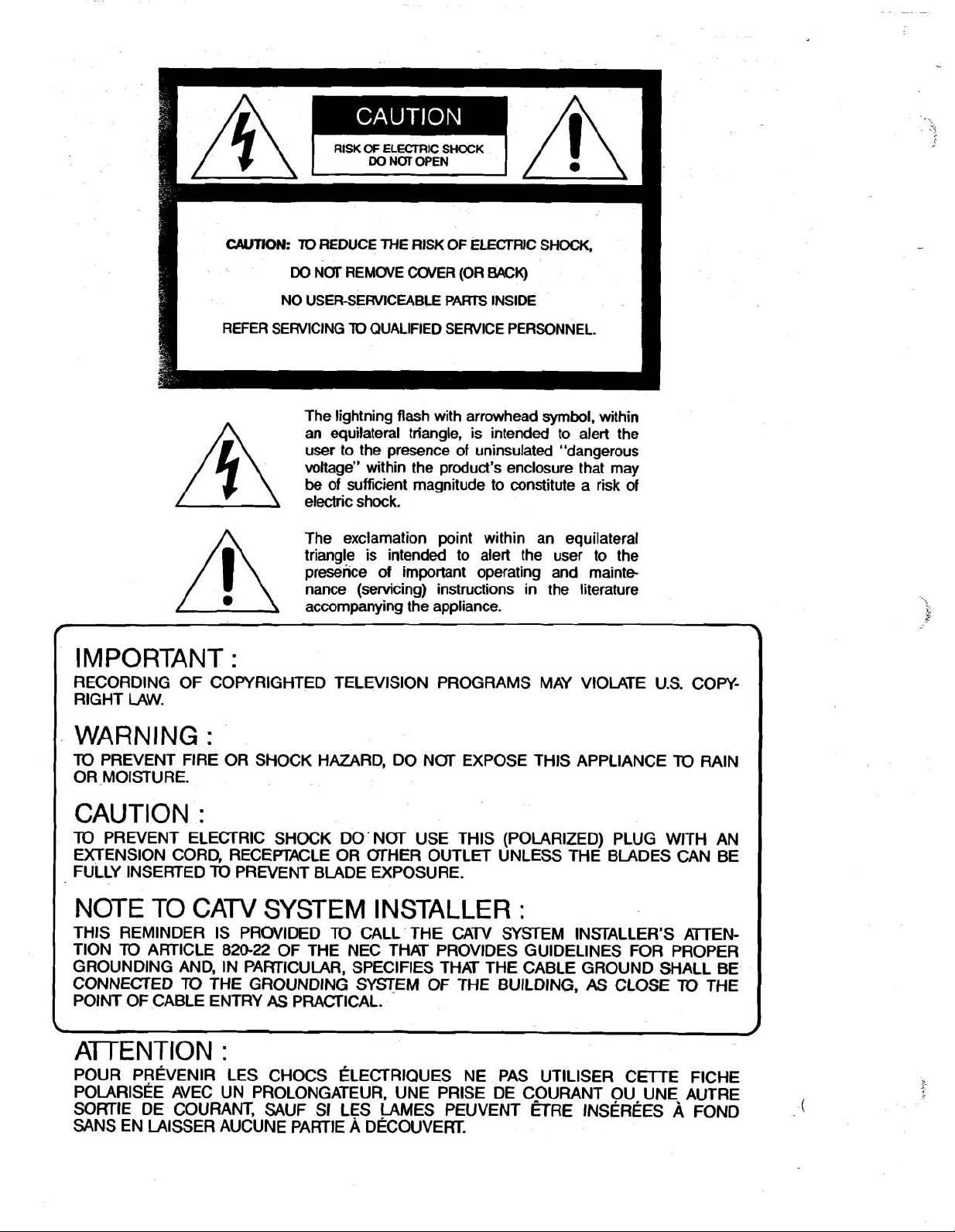
The lightning flash with arrowhead
an equilateral
user to the presence of
voltage" within the product's enclosure that may
be
of sufficient magnitude to constitute a risk of
electric shock.
The exclamation point within an equilateral
triangle is intended to alert the user to the
presence of important operating and
nance (servicing) instructions in the literature
accompanying the appliance.
triangle, is intended to alert the
uninsulated "dangerous
symbol,
within
mainte
TO
3
RAIN
CAUTION
TO
PREVENT ELECTRIC SHOCK DO' NCrr USE THIS (POLARIZED) PLUG WITH AN
EXTENSION CORD, RECEPTACLE OR
FULLY INSERTED
NOTE TO CATV SYSTEM INSTALLER
THIS REMINDER IS PRWIDED
TlON
TO
ARTICLE
GROLlNDlNG AND, IN PARTICULAR, SPECIFIES THAT THE CABLE GROUND SHALL BE
CONNECTED
POINT OF CABLE ENTRY
:
TO
PREVENT BLADE EXPOSURE.
TO
820-22
TO
THE GROUNDING SYSTEM
OF THE NEC THAT PROVIDES GUIDELINES FOR PROPER
AS
PRA(=TICAL.
(STHER OUTLET UNLESS THE BLADES CAN BE
:
CALL THE CATV =STEM INSTALLER'S AmEN-
OF
THE BUILDING,
AS
CLOSE
TO
\
A-TTENTION
POUR PREVENIR LES CHOCS
POLARIS~E AVEC UN PROLONGATEUR, UNE PRlSE DE COURANT OU UNE AUTRE
SORTIE DE COURANT,
SANS EN LAISSER AUCUNE PARTIE
:
ELECTRIQUES
SAUF SI LES LAMES PEUVENT ETRE
A
DECOUVERT.
NE PAS UTlLlSER CETrE FICHE
INSEREES
A
THE
FOND
/
(
Page 3
PLEASE READ ALL THESE INSTRUCTIONS REGARDING YOUR VCR AND RETAIN FOR
FUTURE REFERENCE. FOLLOW ALL WARNINGS AND INSTRUCTIONS MARKED ON
THE
VCR.
1.
Read Instructions
All the safety and operating instructions should
read before the appliance is operated.
2.
Retain Instructions
The safety and operating instructions should
retained for future reference.
3.
Heed
Warnings
All warnings on the appliance and in the operating
instructions should
4.
Follow Instructions
All operating and use
followed.
5.
Cleaning
Unplug this video product from the wall outlet
before cleaning.
cleaners. Use a damp cloth for cleaning.
6.
Attachments
Do
not use attachments not recommended by the
video product manufacturer
hazards.
7.
Water and Moisture
Do
not use this video product near water - for
example, near a bath tub, wash
or laundry tub, in a
ming
pod,
and the like.
8
Accessories
Do
not place this video product on an unstable cart,
stand,
tripod, bracket, or table. The video product
may fall, causing serious injury
and
serious damage to the appliance. Use only
cart,
with a
mended
video product. Any mounting
should
should use a
by
An appliance
moved
uneven surfaces may cause the appliance
combination
by
follow
the
manufacturer.
with care. Quick stops,
be
adhered
Do
not use liquid or aerosol
wet
basement,
stand, tripod bracket. or table
the manufacturer,
the
manufacturer's instructions, and
mounting accessory recommended
and
cart
to.
instructions should
as
they may cause
bowl,
kichen sink,
or
near a
to
a child
or
or
sdd
with
of
the appliance
combination should
excessive
force, and
and
to
averturn.
swim
adult.
recorn
cart
be
be
be
the
be
9.
Wntilation
Slots
and openings in the cabinet are provided for
and
ventilation
video product and
and
these openings must
covered. The openings should never
placing the video product on a
other similar surface. This video product should
never
be
register. This video product should
a built-in installation such
unless proper ventilation is
manufacturer's instructions have been adhered to.
la
Pawer
Sources
This video product should
the type
label.
If
you are
to your home,
local
power company. For video products intended
to operate from battery power, or other sources,
to
the operating instructions.
refer
11.
Grounding or Pblarizatiin
This video product is equipped with a hire
grounding-type plug, a plug having a third (grounding) pin. This plug will only fit into a grounding-type
power outlet. This is a safety feature. If you are unable to insert the plug into the outlet, contact your
electrician to replace your
defeat the safety
plug.
12.
PawerCord Protection
P&wer-supply cords should
not
are
placed upon
attention
cles, and the point
appliance.
13.
Lightning
For
added protection
during a lightning
unattended
unplug
antenna or cable
to
the
video
to ensure reliable o~eration
to
protecl
it
from averheating.
not
be
blocked or
be
blocked
bed,
sofa, rug, or
placed near
of
power source indicated on the marking
not
consult
likely to
or
to
cords at plugs, convenience
and
it
from the wall outlet and disconhect the
product due
or
aver a radiator or heat
not
as
be
sure
of
the type
your appliance dealer or
purpose of the grounding-type
be
against them, paying particular
unused for long perii
svstem. This wll prevent damaae
obsolete outlet.
walked on or pinched
be
where
for
this video product receiver
storm.
or when
to
lightning and power-liie
be
a
bookcase
provided or the
operated only
of
power supply
routed so that they
they
exit
surges
14.
Pbwer Lines
not
be
An outside antenna system should
the vicinity of overhead power lines
ligM or power circuits, or where
power lines or circuits. When installing an outside
antenna system. extreme
keep
fm
contact with them might
touching such power lines or circuits
be
we
it
should
fatal.
or
other
can
fall into such
be
located in
of
the
by
placed in
or
rack
from
Do
not
by
items
recepta-
from
the
it
is left
of
time,
electric
taken
as
to
Page 4
15. Overloading
Do
not werload wall outlets and extension
this
can
result in a
rid
of
fire or electric shock.
16. Object and Liquid Entry
Never push
objects
of
any kind into this
product through openings as they may touch
dangemus voltage points
or
short-out parts that
could result in a fire or electric shock. Never
liquid
of
any kind
on
the
video product.
17. Outdoor Antenna Grounding
If an outside antenna or cable system is connected
to the video
produd,
system is grounded so as
tion against
be
sure the antenna
to
provide some protec-
voltage surges and built-up static
charges
Section 810
ANSllNFPA No.
with respect
of
the National Electrical Code,
70
-
to
1984, provides information
proper
grounding
of
the mast
supporting structure, grounding of the lead-in wire
to an antenna discharge unit. size of grounding
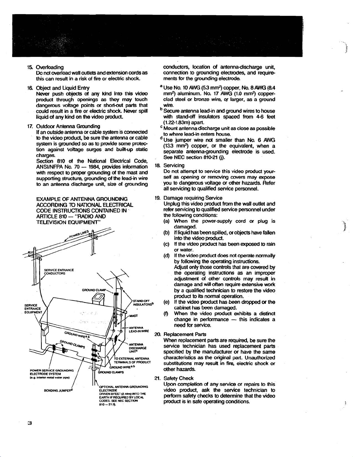
EXAMPLE OF ANTENNA GROUNDING
ACCORDING
TO
NATIONAL ELECTRICAL
CODE INSTRUCTIONS CONTAINED IN
ARTICLE 810 - "RADIO AND
TELEVISION EQUIPMENT"
BONDING
JUMPER*
/
I
I
'
QPTIONAL
ELECTRODE
DRIVEN
8
EARTH
IF
CODES.
SEE
810 - 21
(9.
ANTENNA
FEET
(2.Um) INTO
AEOUUIED
NH:
SECTKm
cord.
video
spin
or
cable
and
'
GROUNDING
THE
BY
LOCM
conductors, location
as
connection to grounding electrodes, and requirements for the grounding electrode.
a Use No. 10 AWG
mrn2) aluminum. No. 17 AWG (11) mrr?) copperclad steel
or
wire.
Secure antenna lead-in and ground wires to house
stand4
with
(1.22-1.83m) apart.
Mount antenna discharge unit as close
to where lead-in enters house.
Use jumper wire not smaller than No.
(133 mm2) copper, or the equivalent, when a
separate
antennagmunding electrode is used.
See NEC section
la
Servicing
Do not attempt to service this video product yourself as opening
you to dangerous voltage or other hazards Refer
all servicing to qualified service personnel.
19. Damage requiring Service
Unplug this video product from the wall outlet and
refer servicing to
the following conditions:
(a) When the power-supply cord
damaged.
(b)
fi
liquid has been spilled,
into the video product.
(c) If the video product has been
or water.
(d)
If the video product does not operate normally
by following the operating instructions.
Adjust only those controls that are
the operating instructions as an improper
adjustment of other
damage and will often require extensive
by
a qualified technician to restore the video
product
,
(e) If the video product has been dropped
cabinet
(f)
When the video product exhibits a distinct
to
has
change in performance
need
for service.
20.
Replacement
When replacement pa& are required.
service technician has used replacement parts
by
specified
the manufacturer
characteristics as the original part. Unauthorized
substitutions may result in fire, electric shock
other hazards
a.
Safety Check
completion
Upon
video product, ask the service technician to
perform safety checks to determine that the video
is
product
in safe operating conditions.
of
antennadischarge unit.
(53
mrr?) copper. No. 8
bronze
wire,
or larger, as a ground
insulators spaced from
810-2l
(j).
or
removing covers may
M
4-6
as
possible
qualified service personnel under
or
or
objects have fallen
exposed
covered
contrds
its
normal operation.
may
result in
been damaged.
-
this indicates a
Parts
be
or
have the same
of
any
service
or repairs to this
(84
feet
6
AWG
expose
plug is
to
rain
by
work
or
the
sure the
or
Page 5
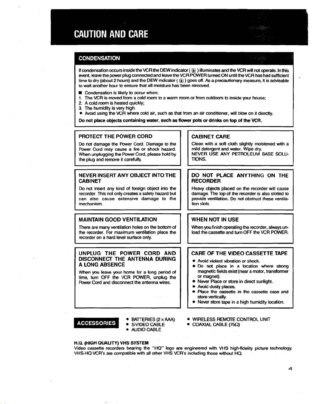
If condensation occurs inside the VCR the DEW indicator
event,
leave the power plug connected and leave the VCR POWER turned ON until the VCR has had sufficient
time to dry (about
to wait another hour
Condensation is likely to occur when:
1.
The VCR is moved from a cold
2.
A cold room is heated quickly;
3
The humidity is very high.
Avoid using the VCR where cold air, such
2
hours) and the DEW indicator
to
ensure that all moisture has been remwed.
room
to a warm room or from outdoors
as
( O )
illuminates and the VCR will not operate. In this
( )
goes off.
that from an air conditioner, will blow on it directly.
As
a precautionary measure,
to
inside your house;
it
is advisable
PROTECT THE POWER CORD
Do
not damage the Power Cord. Damage to the
Power Cord may cause a fire or shock hazard.
When unplugging the Power Cord, please hold by
the plug and remwe it carefully.
NEVER INSERT ANY OBJECT INTO THE
CABINET
Do not insert any kind
recorder. This not only creates a safety hazard but
can also cause extensive damage to the
mechanism.
There are many ventilation holes on the bottom of When you finish operating the recorder, always
the recorder. For maximum ventilation place the load the cassette and turn OFF the VCR POWER.
recorder on a hard level surface only.
of
foreign object into the
UNPLUG 'THE POWER CORD AND
DISCONNECT THE ANTENNA DURING
A LONG ABSENCE
When you leave your. home for a long period of
time, turn OFF the VCR POWER, unplug the
Cord
Power
and disconnect the antenna wires.
CABINET CARE
soft
Clean with a
mild detergent and water. Wipe dry.
NEVER USE ANY PETROLEUM
cloth slightly moistened with a
BASE
SOLU-
DO NOT PLACE ANYTHING ON THE
RECORDER
Heavy objects placed on the recorder w~ll cause
damage. The top
provide ventilation.
tion slots.
of
the recorder is also slotted to
Do
not
obstruct these ventila-
un-
CARE OF THE VIDEO CASSETTE TAPE
Avoid violent vibration or shock.
Do
not
place in a location where strong
magnetic fields exist (near a motor, transformer
or magnet).
Never Place or store in direct sunlight.
Avoid dusty places.
Place the cassette in the cassette
store vertically.
Never store tape in a high humidity location.
case
and
BAJTERIES
SVIDEO CABLE
AUDIO CABLE
H.Q. (HIGH
Video cassette recorders bearing the "HO" logo
VHSHQ VCR's are compatible with all other VHS VCR's including those without HQ.
QUALITY)
VHS
SYSTEM
(2
x
AAA)
WIRELESS REMOTE CONTROL UNIT
COAXIAL CABLE
are
engineered with VHS high-fidelity picture technology.
(XQ)
Page 6
CONNECTION PANEL
@
VIDEO IN 2 and SVlDEO IN
connedom
@
VIDEO INPUT SELECT
@
AUDIO IN 2 connectors EXTERNAL INPUT SELECT
2
MICROPHONE jack
HEADPHONES jack
PHONES LML
switch
contrd
Page 7
@
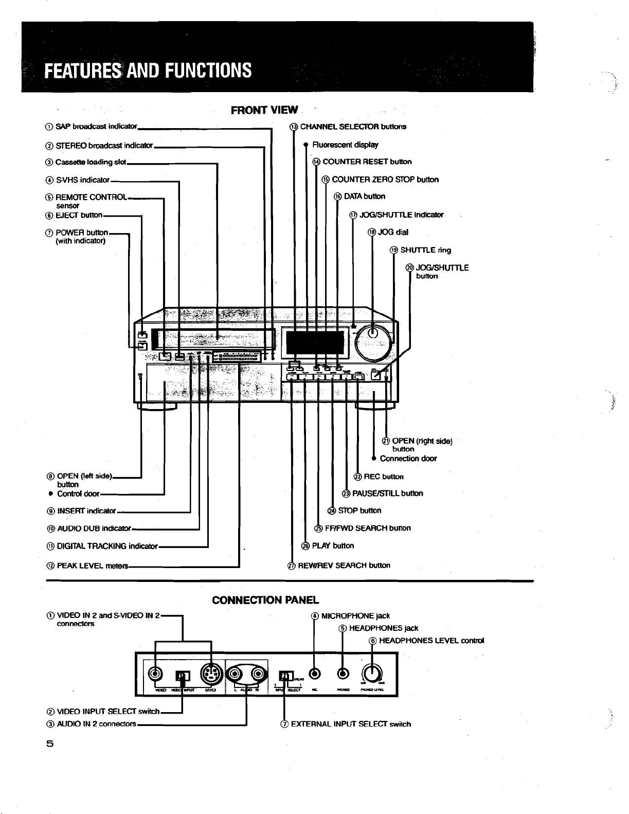
SAP broadcast indicator
llluminates when SAP broadcasts are received.
@
STEREO broadcast indicator
are
llluminates when stereo broadcasts
@
Cassette loading slot
tape
Cassette
@
S-VHS indicator
llluminates during SVHS recording or playback of a
tape
recorded with SVHS system.
@
REMOTE CONTROL sensor
Receives the infra-red light transmission from the
remote control transmitter.
@
WECT button
Press to remove the cassette.
@
POWER button (with indicator)
Press to switch ON power to'the VCR.
@
OPEN (left side) button
Press to open the control door.
@
INSERT indicator
llluminates when the insert edit function is
operating.
@AUDIO DUB indicator
llluminates when the audio dub function is
operating.
@
DIGITAL TRACKING indicator
Flashes to indicate automatic digital tracking ad-
justment. Stops flashing and illuminates to indicate
automatic digital tracking complete.
@
PEAK LEVEL meters
When recording, displays the audio recording level
setting. The following
During recording the audio recording level is displayed. During playback the audio output or
tracking level is displayed, depending on the posi-
of
tion
may also be set to OFF.
@
CHANNEL SELECTOR buttons
Selects the
@
COUNTER RESET button
Press to reset the counter to
is inserted into this slot for loading.
3
functions may be displayed:
the METER SELECT switch. The meters
TV
channel
for
recording.
0~00~00s.
received.
Hi-fi
@
COUNTER ZERO STOP button
When pressed, the tape will fast forward or rewind
until the counter display indicates
automatically stop at that point.
@
DATA button
Press to display the counter, channel, operation
mode and remaining time display on the screen.
@
JOGISHUTTLE indicator
llluminates during
@JOG dial
Refer to
@
SHUTTLE ring
Refer to
@
JOGISHUTTLE button
Press to engage
@I
OPEN (right side) button
Pm
@
REC (RECORD) button
Press to begin recording, both video and audio.
@
PAUSEISTILL button
When pressed during recording, stops movement
of tape temporarily. Press again to continue the
recording. When pressed during playback, stops
movement
sound.
@
STOP button
Press to discontinue all
@
FFlFWD SEARCH button
In stop mode, press to
In playback mode, press for forward speed search.
In playback mode, press and hold for about one
second before releasing for forward high speed
search.
@
PLAY button
Press to playback a previously recorded
@I
REWIREV SEARCH button
In stop mode, press to rewind the tape.
In playback
In playback mode, press and hold for about
second before releasing
search.
JOG
SHUlTLE RING (page 61).
to
open the connection door.
joglshuttle mode.
DIAL (page 62).
joglshuttle mode during playback.
of
tape,
exhibiting a still picture without
tape
fast
forward the tape.
mode,
press for reverse speed search.
for
OH-,
related functions.
tape.
reverse high speed
and
-
one
@
VlDEO IN 2 and S-VIDEO IN 2 connectors
TheVlDEO IN is
VHS VCR or video source. The
to dub from another SVHS VCR (refer to the "DUB
BING" on pages
@
VIDEO INPUT SELECT switch
When dubbing an SVHS tape from another SVHS
VCR set to S
VlDEO position (refer to the "DUBBING"
46
and 47).
@
AUDIO IN 2 connectors
Connect to the audio output
record from that source.
used
to record ordub from another
46
and 47).
(YIC) position. Otherwise leave
SVIDEO IN is used
on
of
an audio source to
it
pages
in
@
MICROPHONE jack
of
Input for connection
(see
bing
@
HEADPHONES
Output for connection
listening.
@
HEADPHONES LEVEL control
Adjusts the headphones output level.
@
EXTERNAL INPUT SELECT switch
When the AUDIO, VlDEO and SVIDEO IN
rear panel are used, set to
When the AUDIO, VlDEO and
connection panel are used, set to 2 position.
page
a microphone for audio dub-
74).
jack
of
headphones for private
1
(REAR) position.
SVIDEO IN
1
of
the
2
of
the
6
Page 8
@)
CAN
(cable)
@
Channel display,-l
@
PROGRAM NUMBER
@
PROGRAM NUMBER
indicators
indicators
indicator
1
FLUORESCENT
,,
11,
@ANT.
@
DISPLAY
Bitulicator
E%
(EXTERNAL)
indicator
Present
time
DEW
indicatw
PROG REC
diilay
indicator
@
CASSETTE SFATUS
indicatw
@
VIDEO
indicator
@
ADDR (ADDRESS)
INDX
(INDEX)
PLAY
indicalwA
@
REC
indicator
@)
EDIT
cuntrd connector
@
HIGH SPEED SEARCH AW
indiicabx
indii-
control
II
I
REAR
'
VIEW
@
TAPE SPEED
@
TAPE REMAIN
VIDEO CHANNEL SELECTOR
TO
N
terminal
indicator
indicator
REPEAT
switch
indii
@
AUDIO OUT
@AUDIO IN 1 connectors
@
VIDEO OUT
mnectors
@VIDEO IN 1 and
connectws
connecm
and
SVlDEO
SVlDEO IN
OUT
OOPfrHRU
ANT.
A
1
terminal
terminal
Page 9
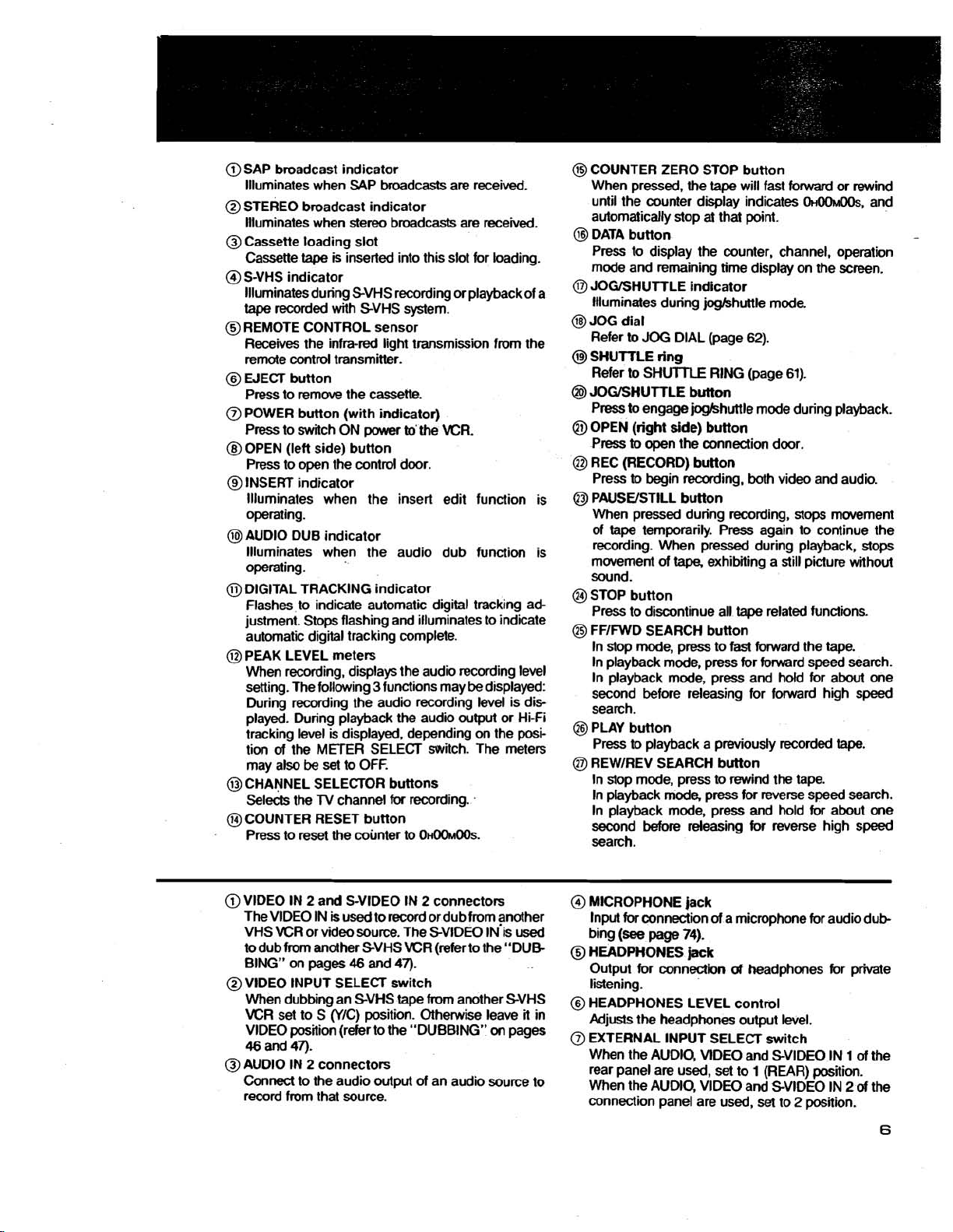
@
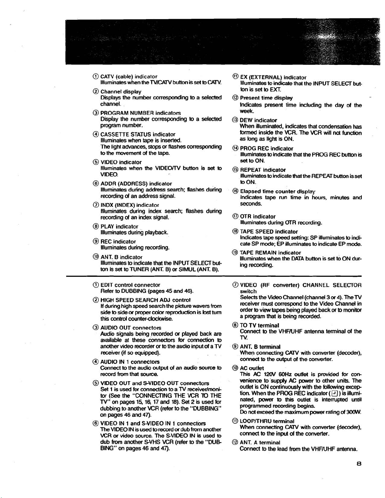
CATV (cable) indicator
llluminates when the
@
Channel display
Displays the number corresponding to a selected
channel.
@
PROGRAM NUMBER indicators
Display the number corresponding to a selected
program number.
@
CASSETTE STATUS indicator
Illuminates when
The light advances, stops or flashes corresponding
mwement
to the
@
VlDEO indicator
Illuminates when the
VIDEO.
@
ADDR (ADDRESS) indicator
llluminates during address search; flashes during
recording
@
INDX (INDEX) indicator
llluminates during index search; flashes during
recording
@
PLAY indicator
llluminates during playback.
@
REC indicator
llluminates during recording.
@
ANT. B indicator
llluminates to indicate that the INPUT SELECT button is
of
an address signal.
of
set
to TUNER (ANT. B) or SlMUL (ANT. B).
TVlCATV button
tape
is inserted.
of
the
tape.
VlDEOrrV button
an index signal.
is
set to CATV.
is
set
to
@
EX (EXTERNAL) indicator
Illuminates to
tonissettom
@I
Present time display
lndicates present time including the day
week.
@
DEW indicator
When illuminated, indicates that condensation has
formed inside the VCR. The
as long as ligM
PROG REC indicator
Illuminates
set
to ON.
@
REPEAT indicator
Illuminates to indicate that the REPEAT button is
to ON.
@I
Elapsed time counter display
Indicates
seconds.
@
OTR indicator
llluminates during
@
TAPE SPEED indicator
Indicates
Gate SP mode; EP illuminates to indicate EP mode.
@
TAPE REMAIN indicator
llluminates when the DATA button is set to ON dur-
ing recording.
indicate that the INPUT SELECT but-
WR will
is
ON.
to
indicate that the PROG REC button
tape
run time in hours, minutes and
OTR recording.
tape
speed
setting: SP illuminates to indi
not
of
the
function
set
-
is
@
EDIT control connector
Refer to DUBBING (pages
@
HIGH SPEED SEARCH ADJ control
If
during high
side to side
this control
@
AUDIO OUT connectors
Audio signals being
available at these connectors for connection to
another video recorder or to the audio input
receiver
@
AUDIO IN 1 connectors
Connect to the audio output
record from that source.
@
VlDEO OUT and S-VIDEO OUT connectors
1
Set
tor
(See
TV"
on pap 15,1617 and 18).
dubbing to another VCR (refer to the "DUBBING"
on
pages 46 and 47).
@I
VlDEO IN 1 and S-VIDEO IN 1 connectors
The VlDEO IN
VCR
or
dub from another SVHS
BING" on pages 46 and 47).
speed
or
proper
counterclockwise.
(if
so
equipped).
is
used
for
connection to a TV receiirlrnoni-
the "CONNECTING ME WR
is
video source. The SVIDEO IN
used to
45
and 46).
search the picture wavers
cdor
reproduction is
.recorded
or
played back
of
an audio source to
TO
Set
2
is
used for
record
or
dub from another
is
WR (refer to the "DUE
from
lost
turn
are
of
a TV
THE
used to
@
VlDEO (RF converter) CHANNEL SELECTOR
switch
Selects the
receiver must conespond to the Video Channel in
order to view
a program that is being recorded.
@
TO TV terminal
Connect to the
TV.
@
ANT. B terminal
When connecting
conned
@
AC outlet
This
venience to supply
outlet
tion. When
nated,
programmed recording begins
Do
not
@
LOOPrrHRU terminal
When connecting
connect to the
@I
ANT. A terminal
Connect to the lead from the VHFNHF antenna.
Vii
Channel (channel
tapes
being played back or
VHFNHF antenna terminal of the
to
AC
12OV
is
ON continuously with
power
exceed
CAW
the output
the
of
60Hz
outlet
AC
PROG REC indicator
to
this outlet is interrupted until
the maximum power rating
CATV
input
of
3
or
4). The TV
to
with converter (decoder),
the converter.
is provided for con-
power to other units. The
the
following
(a
)
of
with converter (decoder),
the converter.
monitor
excep
is
illumi-
300W.
Page 10

CONTROL PANEL
@
PlCTUREwntrol RH: LEVEL controls
@
SVHS sw~tch
@
REMOTE sw~tch
@TRACKING control
@
SnLL ADJUST
@
DIGITAL TRACKING switch
conbol
'
switch
@
VIDEO MUTE switch
@
NORMAL AUDIO sw~tch
Q
WB SELECT switch
@
Programmed recording, channel
and time
Q
TVICAN
@
TAPE SPEED bunon
set
control
button
section
preset------
@
INPUT SELECT button
@
HiFdMIWNORMAL switch
TIMER RESET button
TAPE REMAIN switch
OTR START TIME button
OTR REC TIME button
@
VlDEW button
@
-
button
@
SLOWIFR
@I
+
button
ADV
button
AUDIO MONITOR button
AUDIO DUB button
INSERT button
I
I
&I
Digital screen and munixreen
control
section
Page 11
@
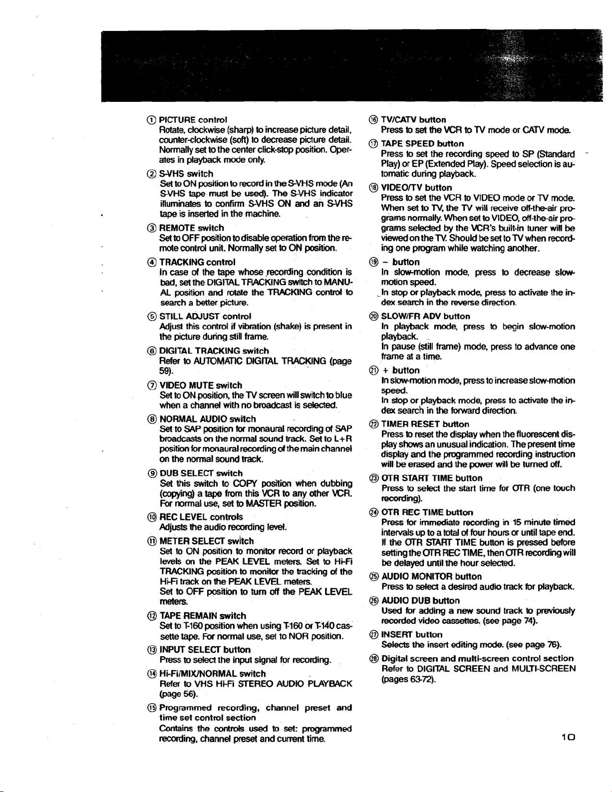
PICTURE control
Rotate, clockwise (sharp) to increase picture detail,
counterclockwise
Normally
ates in playback mode only.
@
S-VHS switch
Set
SVHS
illuminates
tape
@
REMOTE switch
Set
mote control unit. Normally
@
TRACKING control
In
bad,
AL
search a better picture.
@
STILL ADJUST control
Adjust this control
the picture during still frame.
@
DIGITAL TRACKING swiich
Refer
59).
@
VIDEO MUTE switch
Set to ON position, the
when a channel with no broadcast
@
NORMAL AUDIO switch
Set
broadcasts
position for monaural recording
on
@
DUB SELECT switch
Set
(copying) a
For
@I
REC LEVEL controls
Adjusts the audio recording
@
METER SELECT swhch
Set to ON position
levels
TRACKING position
Hi-Fi track on the PEAK LEVEL meters.
Set
meters.
@
TAPE REMAIN switch
Set
sene
@I
INPUT SELECT button
Press
@
Hi-FiIAIIIXINORMAL switch
Refer
@age
@
Programmed recording, channel preset and
time set control section
Contains
recording, channel
set
to
ON position to record in the SVHS mode (An
tape
is
inserted in the machine.
to
OFF position to disable operation
case
of
set
the DIGITAL TRACKING Mtch to MANU-
posiliin
to
AUTOMATIC DlGrrAL TRACKING (page
to SAP position
the
normal sound track.
this switch to
normal use,
on
the PEAK LEVEL meters.
to
OR
to
Ti60
tape.
to
select the input signal for recording.
to
VHS HFFi
56).
the
(soft)
to decrease picture detail.
to the center click-stop position. Oper-
must
be
used).
The
to
confirm SVHS ON
SVHS indicator
and
an SVHS
from
set
to
ON position.
the
tape
whose
,recording condin is
and
rotate the TFWKING contrd to
if
vibration (shake) is present in
TV
screen will switch
is
selected.
for
on
the normal sound track.
tape
monaural recording
COPY
position when dubbing
from this
set
VCR
to
MASTER position.
of
Set
the main channel
to any other KR.
level.
to
monitor record or playback
to
monitor the tracking
piti
position when using
For
to
turn
off
normal use, set to NOR position.
STEREO
controls
used
preset
and cunent time.
to
Set
the PEAK LEVEL
M60
orM&
AUDIO PLAYBACK
set:
programmed
the
re
to
blue
of
SAP
to L+R
to
Hi-Fi
a4
the
cas-
@
TVlCAN button
Press
to
set
the KR
@
TAPE SPEED button
Press to set the recording speed to SP (Standard
Play) or EP (Extended Play). Speed selection is automatic during playback.
@
VlDEO/TV button
set
Press to
When
grams normally. When
grams selected
viewed
ing one program while watching another.
@
-
button
In slow-motion mode, press to decrease slowmotion speed.
.
In
stop
dex search in the reverse direction.
@
SLOWIFR ADV button
In playback mode, press to begin slow-motion
playback.
In pause (still frame) mode, press to advance one
frame at a time.
@
+
button
In
sbmotion mode, press to increase slow-motion
speed.
In stop or playback mode, press to activate the
dex search in
@I
TIMER RESET button
Press
play
shows an unusual indication. The present time
display
will
be
@I
OTR START TlME button
Press
recording).
@
OTR REC TlME button
Press for immediate recording in 15 minute timed
intervals up to a
If
the
setting the
be
delayed until the hour selected.
@I
AUDIO MONITOR button
Press
@
AUDIO DUB button
Used
recorded video
@
INSERT button
Selects
@
Digital screen and multi-screen control section
Refer to DIGITAL SCREEN and MULTI-SCREEN
(pages
the VCR to VIDEO mode
set
to
TV,
on the
or
playback mode, press to activate the
to
reset the display when the fluorescent dis-
and
the programmed recording insbuction
erased
to
select the start time for (XR (one touch
(XR
START
OlTl
to
select
for
adding a new sound track
the insert editing
6372).
to
TV
mode or
the
TV
will receive off-the-air pro-
set
to VIDEO, off-theair pro-
by
the KR's built-in tuner
TV.
Should
be
set to
the
forward direction.
and
the power will
total
of
four hours or until tape end.
TlME button is
REC
TIME, then (XR recording will
a desired audio track for playback.
cassettes.
(see
mode.
TV
be
pressed
page
(see
CATV
or
TV
when record-
turned
to
previously
74).
page 76).
mode.
mode.
wil
be
off.
before
-
in-
in-
Page 12

Transmission window
1:
Transmission
dicatw.
COUNTER RESET button
Press to reset the cou
OHOOMOOS.
When pressed, the tape
forward
display indicates
automaticalty stop at that point.
Indlcator MUUI-SCREEN (pages
or
rewtnd until the counter
w~ll
OH00h100S.
and
, , , ,
, , ,
,Programmed
(See pages
Dial screen and muttCscreen
control
Use for DIGITAL SCREEN and
SKIP SEARCH button
Press to begin skip search.
AUDIO MONITOR button
Press to
channel
REPEAT button
Press
INPUT
Press to select the input signal for
recording
37.36.38.
section
select
the desired audio
for
playback
for
repeat
playback.
SELECl button
and
6S72).
secHon
40.)
LAPSED
VlDEOlTV button
VCR tuner (VIDEO)
channels selected
NUMBER button
RANDOM ACCESS CHANNEL DRESS ENTER button
SELECTION (page
ELAPSED
:"Lk,sED TWE smRcH
'PSdoGRAMMING mR RECORD ADDRESS SEARCH
ING
(page
RECORDING ADDRESS SIG-
Press to display the counter, channel, operation mode and remaining
lime display
21)
TIME SETTING
41)
on
screen.
(page
(pap
\LJ~~REVERSE
Used for RECORDING THE INDEX
SIGNAL AND ADDRESS SIGNAL
In playback mode,
reverse
In pause (dill frame)
for
TlME SEARCH button
selected time
SEARCH button
SIDWIFR
slowmotion.
reverse
frame
(see
page 24).
AW
press
mode,
advanca
button
to begin
press
Page 13
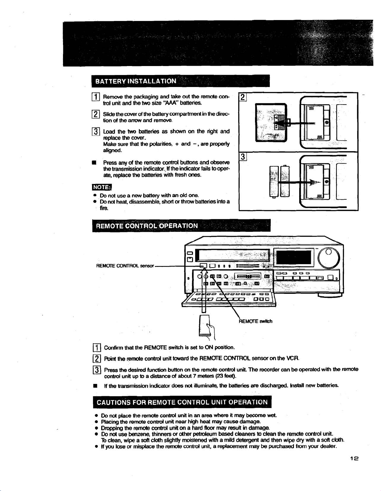
Remove
trol
unit
Slide
the
of
the
tion
the packaging and
and
the
two
size
cover
of
the baltery compartment in the direc-
am
and
remove.
take
"AAA"
out
the reme
batteries.
am
Load the
replace
Make
aligned.
Press
a
the transmission indicator.,
ate,
the wver.
sure
any
replace
two
that
of
the
the
Em34
Do
nol
use a new battery
Do
not
heat, disassemble, short or throw batteries into a
fire
REMOTE
CONTROL
batteries
the
batteries
sensor
as
polarities, + and
remote
contrd
with fresh ones.
with
shown on the right and
-
,
are
properly
buttons and
If
the indicator
an
old one
fails
observe
to
oper-
Confirm
Point
Press
control
If
Do
Placing
Dropping
Do
To
If
you
that
the
the
remote conhol unit tward
the
desired
unit up
the
transmission indiior
nd place the remote
the
remote control unit near high heat may cause damage
the
not
dean,
remote
use
benzene,
wipe a
lose
or misplace the remote control unit, a replacement may
REMOTE
function
to
a
soff
switch
is
button
on the remote
distance
contrd
thinners or other petroleum
cloth slightly moistened
of
about
does
not
control
unit in an area where
unit
on
set
the
7
meters
illuminate,
a
hard
to
ON
position.
REMOTE
(23
Roor
may
with
CONTROL
control
feet).
the
batteries
it
may
result
based
a mild
\
REMOTE
unit.
The
become
in
damage.
cleaners
detergent
witch
sensor
w\
the
KR.
recorder
are
discharged. Install new batteries
to
and then wipe dry with a
be
can
be
operated with
wet.
clean
the remote control unit.
purchased
from
your dealer.
soft
the
cblh.
remote
Page 14
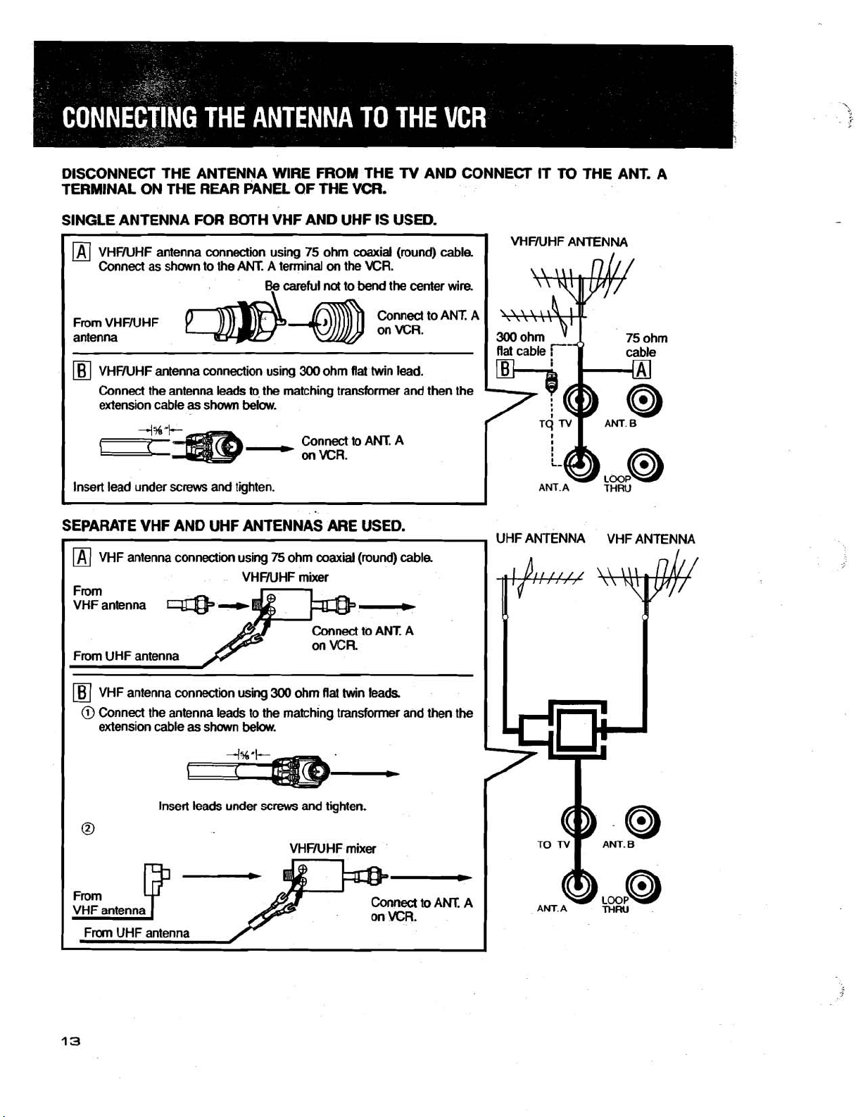
DISCONNECT THE ANTENNA WIRE FROM THE TV AND CONNECT IT
TERMINAL ON THE REAR PANEL. OF THE VCR.
SINGLE ANTENNA FOR BOTH VHF AND UHF IS USED.
VHFNHF
TO
THE ANT. A
ANTENNA
Conned to
Connect the antenna leads
extension cable as shown below.
to
the matching transformer and then the
Connect to
ANT. A
SEPARATE VHF AND UHF ANTENNAS ARE USED.
[Bj
VHF
antenna connection using
@
Connect the antenna leads to the matching transformer and then the
extension cable as shown below.
300
ohm
flat
twin leads
ANT. A
UHF
ANTENNA
VHF
AN
Insert leads under
screws
and tighten.
Page 15
Connect to ANT A on VCR
TO
N
ANT.B
I
From CAW (CABLE)
4
ANT. A
LOOP
THRU
@
w
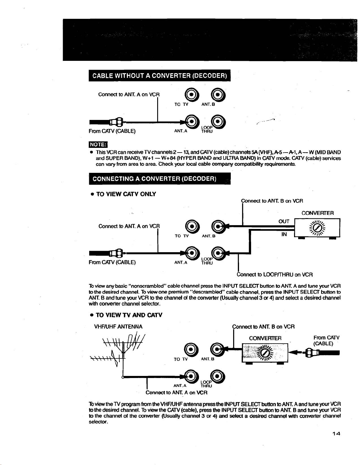
This VCR
and
can
TO VlEW CATV ONLY
Connect
From
Toview any basic "nonscrambled" cable channel press the INPUT SELECT button
to
the desired channel. To view one premium "descrambled" cable channel, press the INPUT SELECT button to
ANT. B and tune your VCR to the channel
with converter channel selector.
can
SUPER BAND),
vary
receive TV channels
W+1- W+84
from area to area. Check your local cable company compatibility requirements.
2
-
13,
(HYPER
and
CAW
(cable) channels
BAND
and ULTRA BAND) in
54
(VHF),
Connect to ANT. B on VCR
I
I
to
ANT. A on VCR
I
CATV (CABLE)
TO
N
ANT.A
of
8
the
6
ANT.B
THRU
hnect to LOOPKHRU on VCR
converter (Usually channel 3 or
I,
A5 - Al,
CAW
mode. CATV (cable) services
OUT
to
4)
and select a desired channel
IN
ANT. A
A
-
W
CONVERTER
+\w,
$@$
0
I
and
tune your VCR
(MID BAND
'/
1
\\'
-
TO VlEW
VHFNHF ANTENNA Connect
b
view
to
the desired channel. To
to
the channel of the converter (Usually channel 3 or
selector.
TV
AND CATV
AM. A
the TV program from the VHFNHFantenna
view
the
CAW
(cable),
THRU
press
the INPUT SELECT button
press
the INPUT SELECT button
4)
and
select a desired
to
ANT. B on VCR
to
to
channel
ANT. A and tune your VCR
ANT. B and tune your VCR
with
converter channel
Page 16
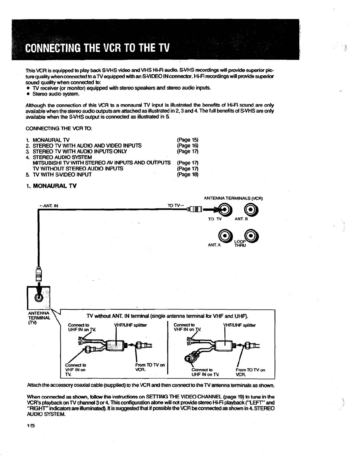
This VCR
ture qualii when connected
sound qualii when
Although the connection
available when the stereo audio outputs are attached
available when the SVHS output is connected
is
equipped
lV receiver (or monitor) equipped with stereo speakers and
Stereo audio system.
to
play back SVHS video
to
connected
alV equipped
to:
of
this VCR
and
VHS H~I audii SVHS recordings will
with
an
WIDE0 IN connector. Hi-Fi recordings
to
a monaural lV input is illustrated the benefits
as
as
illustrated in
stereo
illustrated in
5
audii inputs.
2.3
and
4.
The
prcwide
will
of
Hi-Fi sound are only
full benefits
superior
pdde superior
of
SVHS
are
pb
only
CONNECTING THE VCR
1. MONAURAL TV (f=age 15)
2.
STEREO
3.
STEREO
4.
STEREO AUDIO SYSTEM
M~UBISHI
lV WITHOUT STEREO AUDIO INPUTS
5
lV WITH SVlDEO INPUT
1.
MONAURAL
lV
WITH AUDIO AND VIDEO INPUTS
lV
WITH
l~
TO:
AUDIO INPUTS ONLY
WITH
STEREO
TV
AV
INPUTS
AND
WPUTS
(f=age
16)
(Page 13
(Page 11)
(page 13
(Page 18)
I
ANTENNA TERMINALS (WR)
ANT.A THRU
ANTENNA
TERMINAL
0%
Attach the accessory coaxial cable (supplied) to the VCR
When connected
VCR's playback
''RIGHT" indibtors
AUDIO SYSTEM.
Conned
VHF
TV.
1
as
on
IN
on
shawn,
lV
channel
are
illuminated).
lV
to
follaw
without
the
3
or
4.
This
tt
is suggested that
ANT.
IN terminal (single antenna terminal
VCR.
instructions on SMNG ME VIDEO CHANNEL
confguration alone will
for
VHF and UHF).
Connect
and
then connect to the lV antenna terminals
not
if
possible
the
to
Conned
UHF
provide
VCR
be
to
IN on
TV.
stereo
HpFi
connected
(page
as
From
VCR.
19)
playback
shown in
TO
TV
as
shown.
to
tune in the
("LEFT"
4.
!STEREO
on
and
Page 17
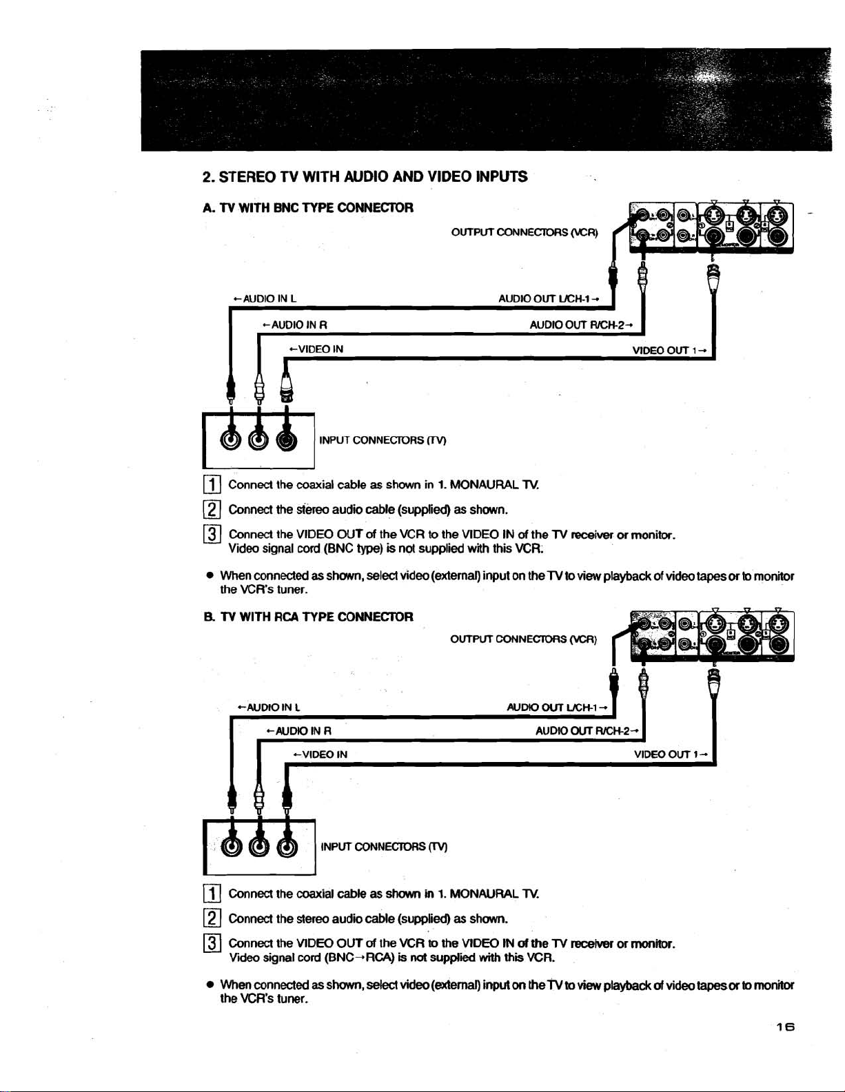
2.
STEREO TV WlTH AUDIO
A.
TV
WlTH
BNC TYPE CONNEClOR
AND
VlDEO
INPUTS
OUTPUT CONNECTORS
i-1
INPUT CONNECTORS
0
(VCR)
VlDEO OUT
[
1
-
m
rn
Connect the coaxial cable
rn
Connect
Connect the VlDEO OUT
Video signal
When connected
the VCR's tuner.
B.
TV
WlTH
the
siereo audio cable (supplied)
cord
RCA
TYPE
(BNC
as
shown, select video (external) input on the
as
shown in
of
the VCR
type)
is
not supplied
CONNEClOR
1.
MONAURAL
as
shown.
to
the VIDEO IN
with
this VCR.
OUTPUT CONNECTORS
of
TV.
the
TV
receiver
TV
to view playback of video tapes
(VCR)
or
monitor.
or
to
monitor
+AUDIO IN
rn
Connect the coaxial cable as
rn
Connect the stereo audio cable (supplied)
Connect the VIDEO OUT
Video signal
When connected
the VCR's tuner.
L
+AUDIO IN
R
+VIDEO IN VIDEO OUT 1
INPUT CONNECTORS
J
shown
of
the VCR m the VlDEO
cord
(BNC+RCA)
as
shown, select video (external) input
is
in
not
0
1.
MONAURAL
as
supplied
shown.
with
AUDIO
IN
of the
this
on
TV
VCR.
the
OUT
AUDIO
TV
TV
WH-I
OUT
receiver
m
view
-
RICH-2-
or
playback
monitor.
of
video
-
tapes
or
to
monitor
Page 18
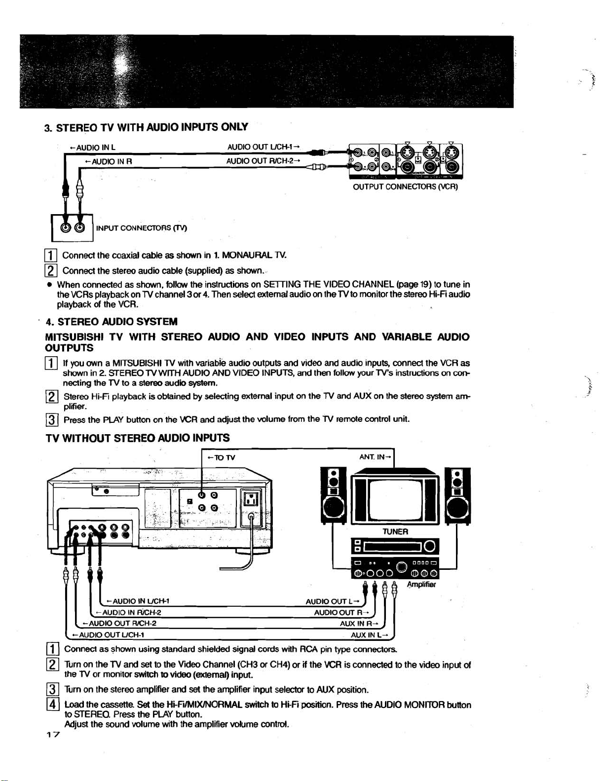
3.
STEREO TV WlTH AUDlO INPUTS ONLY
INPUT CONNECTORS
rn
Connect the coaxial cable
rn
Connect the stereo audio cable (supplied)
When connected
the VCRs playback on
playback of the VCR.
4.
STEREO AUDlO SYSTEM
as
shown, follow the instructions on SWING THE VIDEO CHANNEL
TV
CN)
as
shown in
channel 3 or 4. Then select external audio on the
1.
MONAURAL
as
shown..
TV.
MlTSUBlSHl TV WlTH STEREO AUDlO AND VIDEO
OUTPUTS
rn
If you own a MlTSUBlSHl
shown in
necting the
Stereo Hi-Fi playback
pliier.
press the PLAY button on the VCR and adjust the volume from the
2.
STEREO
TV
to a stereo audii system.
lV
with variable audii outputs and video and audio inputs, connect the VCR
TV
WITH AUDlO AND VIDEO INPUTS, and then follow your TV's instructions on
is
obtained by selecting external input on the
TV WITHOUT STEREO AUDlO INPUTS
-TO
N
(page
19)
TV
to monitor the stereo Hi-Fi audio
to tune in
INPUTS AND VARIABLE AUDlO
as
con-
TV
and AUX on the stereo system am
TV
remote control unit.
ANT. IN-.
(-AUDIO OUT
Connect as shown using standard shielded signal cords with RCA pin
rn
Turn on the
the
TV
or monitor switch
Turn on the stereo amplifier and
Load the
to STEREO. Press the PLAY button.
Adjust the sound volume with the amplifier
17
UCH-1
lV
and
cassette.
set
to the Video Channel (CH3
to
video (external) input.
set
the amplifier input selector to AUX position.
Set
the HiFi/MIX/NORhAAL switch
volume control.
or
CH4) or
to
Hi-Fi
AUX
IN
L-.
J
type
connectors
if
the VCR is connected to the video input of
position. Press the AUDlO MONITOR button
Page 19

5.
TV
WITH SYIDEO INPUT
If your
lV
is equipped with SVlDEO INPUT connector and then connected it
SVHS
playback
is
available.
as
shm below, the full benefit of
OWPUT TERMINALS (XR)
Connect the antenna leads
Connect the stereo audio cable (supplied) as shown.
as
shown in
1:
MONAURAL
W.
r
CONNECTION OF SCONNECX'OR:
Line
up the groove in
wiUt
the projecting part
and
insert.
the
connector
of
the
\
plug
Connect
Refer to the
An AC
supply
PhHer
is plugged into an
When the
er
to
this
begins.
ing terminates. This configuration allows the
gramrned recording timer
for
purposes
Do
the
WIDE0 OUT
lV
mers manual on
120V
60Hz
outlet is
AC
power to other units.
to
this outlet
PROG REC indicator
outlet
Pawer is switched
not
exceed
is
on
AC
outlet with the following exception:
is
interrupted until programmed recording
of
audio only recording
the maximum power rating
of
the VCR to the WIDE0 IN
provided
continuously
(a)
off
when programmed
to
function
how
b
select
for convenience to
as
long
as
the VCR
is
illuminated,
as
an
audio timer
(see
page
50).
of
the SVlDEO IN
pow
record-
pm
30(IW.
of
the
TV
of
using
the
Svideo
lV.
cable (supplied).
Page 20

IF YOU CONNECTED YOUR VCR AS SHOWN ON THE PREVIOUS PAGE
TV
AUDIO AND VIDEO INPUTS OF YOUR
TV
THE VCR SWITCH YOUR
REGARD
THIS PAGE.
8
OR MONITOR TO VIDEO OR EXTERNAL INPUT AND DIS-
cT'E-m
cH4
VlOEO
CHANNEL
OR MONITOR) THEN TO VIEW PLAYBACK OF
%
(i-e.
TO THE
\
Select the VCR Video Channel
is not being used for
Press the POWER button
Press the VlDEOrrV button
-
14
Seled any channel (using the KR CHANNEL SELECTiOR buttons) to
area.
Turn
ON the
For a push-button
If CH3 or CH4, conesponding to the KR Video Channel, is not present on your
unoccupied channel
See
When setting the
more convenient if the position
Video Channel. Generally,
one (in a horizontal arrangement).
For
selected in
knob
lV
lV
Instruction Book
a rotary channel selection
and adjust for
TV
receiver and set
type
TV
ljJ
If the picture
best
by
broadcasts in your area.
to
channel selection
and
video
setting the VIDEO CHANNEL SELECTOR switch to CH3 or 4 whichever
ON.
to
VIDEO.
to
CH3 or 4
to
lV.
adjust
to
obtain a
for
details.
channel selector position, particularly on
which is shown when the
this
channeb
TV,
you
picture detail.
is
select channel 3
selected in
correspond with the Video Channel selected in
cdor
picture
of
the
top
one (in a vertical arrangement)
or
4 depending on the VCR Video Channel
is
not clear, push in the fine
Ima
A clear picture will not
Channel.
optional method may
If
difficulties are encountered, or a dear picture with color
Set the
Press the POWER button to ON.
Play back a prerecorded
Adjust the
The
TV
to the Video Channel (3 or 4).
lV
lV
receiver fine tuning until a clear picture with color is obtained.
is now properly finetuned to the Video Channel.
be
be
.obtained in these steps unless the
used:
tape.
J
receive
the program selected in
lV
is first switched
soft
a
lV
broadcast in your
B
touch
TV's,
on
or
TV
tune adjustment
TV
is properly fine-tuned to the Video
cannot
be
obtained, the following
m
TV.
select an
it
is
usually
is used
the furthest left
as
the
you
Page 21
This VCR
access channel selection and channel memory function. A
Broadcast
(SUPER BAND).
is
equipped with a frequency synthesizer (FS) electmic tuning system. The FS !system
Mal
of
181
channels
37-64
2-13
(VHF),
(HYPER BAND),
14-69
(UHF) and cable
6594
(CAW)
(ULTRA BAND),
channels
channels
9599
(MID BAND) and
1-13
can
(VHF),
be
14-22
100-125
pr(n/ides
selected and include:
(MID BAND),
(ULTRA BAND).
mia
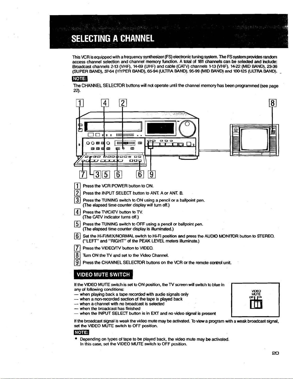
The
CHANNEL SELECTOR buttons will not operate until the channel memory has been programmed (see page
22).
Press the VCR POWER button to ON.
Press the INPUT SELECT button to ANT. A or ANT.
Press the TUNING switch to ON using a pencil or a ballpoint pen.
(The elapsed time
Press the TVICATV button to
(The
CATV
Press the TUNING switch to OFF using a pencil or ballpoint pen.
(The elapsed time counter display is illuminated.)
Set
the HifilMIXINORMAL switch to Hi-Fi position and press the AUDIO MONITOR button to STEREO.
("LEFT" and "RIGHT"
Press the
Turn ON the
Press the CHANNEL SELECTOR buttons on the VCR or the remote control unit.
VlDEOrrV button to VIDEO.
counter display will turn
indicator turns off.)
of
the PEAK LEVEL meters illuminate.)
TV
and
set to the Video Channel.
off.)
TV.
8.
random
23-36
-
If the
VIDEO MUTE switch is set to ON position, the
any of following conditions:
-
when playing back a tape recorded with audio signals only
-
when a non-recorded
-
when a channel with no broadcast is selected
-
when the broadcast has finished
-
when the INPUT SELECT button is in
If
the broadcast signal
set the VIDEO MUTE switch to OFF position.
Depending on types of tape to
In this case, set the VIDEO MUTE switch to OFF position.
section
is
weak the video mute may
of
the tape is
UCT
be
played back, the video mute may
TV
played
and no video signal
be
activated. To
screen
back
will
switch to blue in
is
present
view
a program with a
be
activated.
weak
broadcast
signal,
Page 22
Random
channel number using the NUMBER buttons
For
access
channel
exampie, to receive channel
selection
of
aH VHF (2-13) and UHF (14-69) channels
"23
press 2 and 3 buttons and then the CHANNEL SELECT button in sequence.
!.ma
Since there are no channel numbers Q 1 or
unchanged.
is
operated
(0-9)
and the CHANNEL SELECT button on the remote contrd unit.
m99,
if
these channel numbers
are
by
pressing the desired
pressed the channel remains
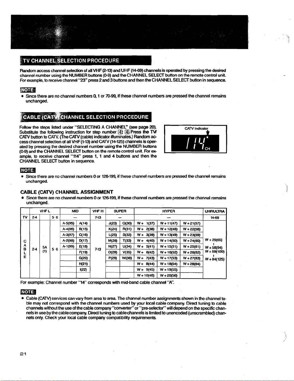
Follow the steps listed under "SELECTING A CHANNEL"
Substitute the following instruction
CATV button to CATV. (The
cess channel selection
ated
by
pressing the desired channel number using
(0-9)
and the CHANNEL SELECT button on the remote contrd unit.
ample,
to
receive channel "114" press 1. 1 and 4 buttons and then the
CHANNEL SELECT button in sequence
CATV
of
all VHF (1-13) and
for
step number
(cable) indicator illuminates) Random ac-
CATV
@
(14-125) channels
the
NUMBER buttons
ma
Since there are no channel numbers
unchanged.
CABLE (CATV) CHANNEL ASSIGNMENT
Since there are no channel numbers
unchanged.
0
or
126199, if these channel numbers are
0
or
12M99,
if
these channel numbers
(see
a.
Press
page
the
is
For
20).
TVI
oper-
ex-
pressed
are
pressed the channel remains
the channel remains
For example: Channel number
Cable (CATV) services can
ble may not correspond with the channel numbers used
channels without the use
use
nels in
nels
by the cablecompany. Direct tuning
only.
Check your
"14" corresponds
vary
from
area
of
the cable company "converter" or "preselector" will depend on the specific chan-
local
cable
company
with
to area. The channel number assignments shown in the channel
to
compatibility requirements
midband cable channel
by
your local cable company. Dired tuning
cablechannels is limited
"A".
to
to
unencoded (unscrambled) chan-
ta-
cable
Page 23
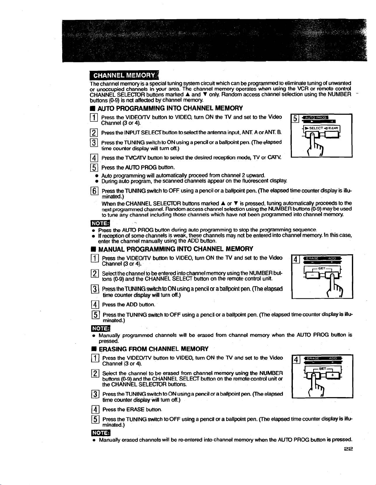
The channel memory is a special tuning system circuit which can
or unoccupied channels in your area. The channel memory operates when using the VCR or
CHANNEL SELECTOR buttons marked A and V only. Random access channel selection using the NUMBER
buttons (0-9) is not affected by channel memory.
be
programmed to eliminate tuning of unwanted
remote contrd
AUTO PROGRAMMING INTO CHANNEL MEMORY
Press the VlDEOrrV button to VIDEO, turn ON
Channel (3 or 4).
)
Press the INPUT SELECT button to select the antenna input, ANT. A or ANT.
-
Press the TUNING switch
time counter display will turn off.)
Press the
Press the
Auto programming will automatically proceed from channel 2 upward.
During auto program, the scanned channels appear on the fluorescent display.
Press
mnated.)
When the CHANNEL SELECTOR buttons marked
next programmed channel. Random access channel
to tune any channel including those channels which have not been programmed into channel memory.
TVICATV button
AUTO
PROG button.
the
TUNING switch to OFF using a pencil or a ballpoint pen. (The elapsed time counter display
to
ON using a pencil or a ballpoint pen. me elapsed
to
select the desired reception
the
TV and set to the Video
R
mode,
TV or
CATV.
A
or V is pressed, tuning automatically proceeds to the
selection using the NUMBER buttons (0-9) may
be
is
illc
used
mi3
Press the AUTO PROG button during auto programming to stop the programming sequence.
If reception
enter the channel manually using the ADD button.
of
some channels is weak, these channels may not be entered into channel memory. In this case,
MANUAL PROGRAMMING INTO CHANNEL MEMORY
Press the VlDEOrrV button to VIDEO, turn ON the TV and set to the
[I1
Channel (3 or 4).
be
Select the channel to
'
tons
(0-9)
and the CHANNEL SELECT button
Press
the TUNING
time counter display will turn off.)
Press the ADD button.
Press the TUNING switch to OFF using a pencil or a ballpoint pen. pe elapsed time counter display
mnated.)
entered intochannel memory uang the NUMBER but-
switch
to
ON
using
a
pencil
on
the remote conm unit.
or
a
ballpoint
pen.
(Ihe
Vi
elapsed
is
ill*
Llmm
Manually programmed channels will
pressed.
ERASING FROM CHANNEL MEMORY
Press the VlDEOrrV button to VIDEO, turn ON the TV and set to the Video
Channel (3 or 4).
Select the channel to
buttons (0-9) and the CHANNEL SELECT button
the CHANNEL SELECTOR buttons.
Press the TUNING switch to ON using a pencil or a ballpoint pen. (The elapsed
time counter display will turn off.)
Press the ERASE button.
Press the TUNING switch to OFF using a pencil or a ballpoint pen. me elapsed time counter display
minated.)
be
erased from channel memory using the NUMBER
mi3
Manually erased channels will
be
be
erased from channel memory when the AUTO PROG button
on
the remote contrd unit
reentered into channel memory when the AUlO PROG button
or
is
pressed.
is
iHw
-
is
Page 24
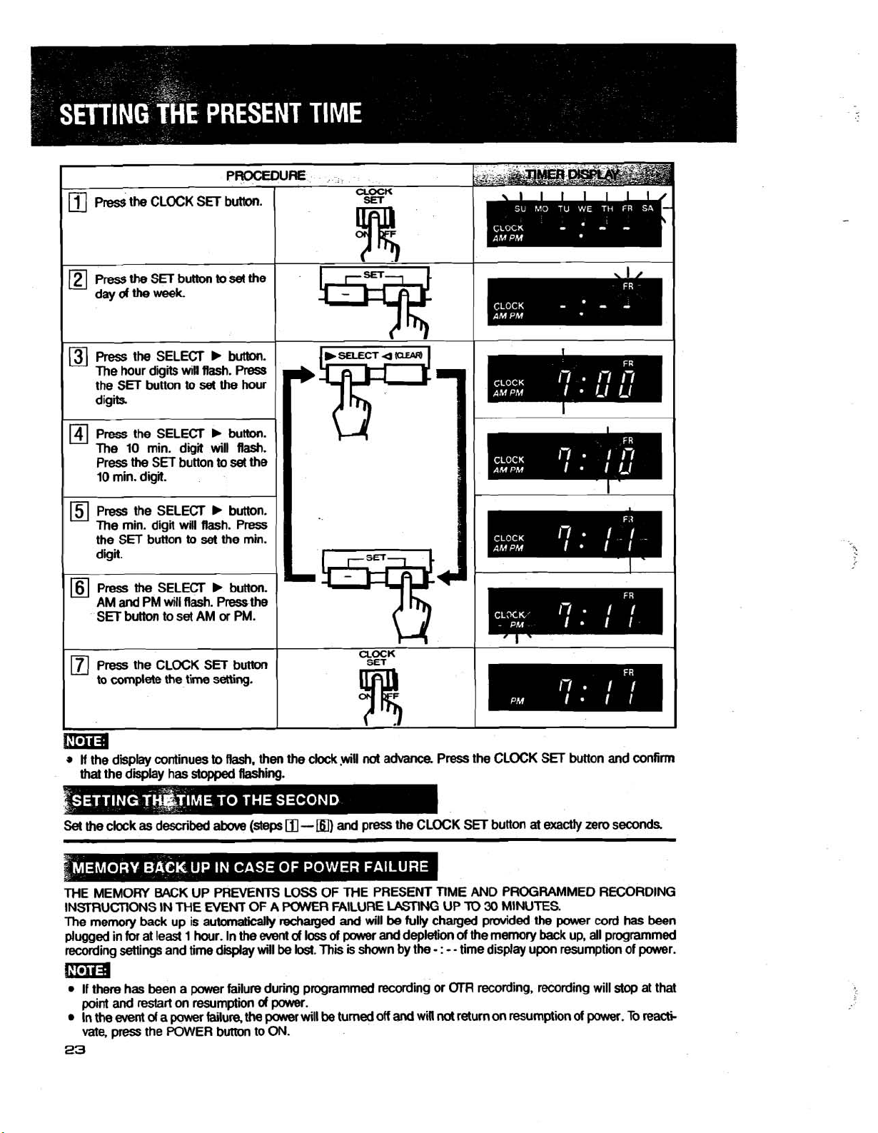
Press the CLOCK SET button
to
complete
the time setting.
UOCK
I
I
\
.I
!ma
w
If
the display continues
that the
Set
THE MEMORY BACK UP PREVENTS LOSS OF THE PRESENT
IN!5IRUCTiONS IN THE
The
plugged in
recording
the
clock
memory
display has
as described
back
for
at least 1 hour. In the
settings
and time display will be lost.
to
Rash. then the
stopped
up is automatically recharged
above
NEM
Rashing.
(steps
OF A PMR FAILURE
event
d
clock
-
loss
m)
This
.yiwiH
not
advance. Press the CLOCK SET button
and
press the CLOCK SET button
LASnNG
and
will
be
of
power
is shown by the
fully charged provided the power
and
depletion
ma
m
If there has been a power failure during programmed recording or
and
restart
on resumption d power.
of
a
power
failure, the pawer will
be
turned off
and
will
23
point
In the
event
vate,
press the POWER button to ON.
I
and
at
exactly
zero seconds
TIME
AND PROGRAMMED RECORDING
UP
TO
30
MINUTES.
cord
of
the memory
- : -
-
time display upon resumption of power.
(XR
recording, recording will
not
return on
back
up, all programmed
resumptptkm
of
power.
confirm
has been
stop
at that
To
rea&
I
Page 25

THIS VCR INCORPORATES AN ELAPSED TlME COUNTER WHICH SHOWS TAPE RUN TlME
IN HOURS, MINUTES AND SECONDS. SINCE THE COUNTER WORKS BY DETECTING A
CONTROL SIGNAL,
FORWARD OR REWIND OPERATIONS.
ACCURATE TlME DISPLAY IS MAINTAINED EVEN THROUGH FAST
Displays
EXAMPLE:
I
The counter number can be replaced
tape
run time in hours, minutes
Tape has been running for 1 hour,
and
15
seconds.
Pressing
The elapsed time counter
with tapes that have not
The elapsed time counter will not function when the VCR is in any
The elapsed time counter displays the time as fdlaws.
the
COUNTER RESET
works
yet
been recorded.
VCR power is OFF. *The PROG LIST button
The
GfFl
is
being used. Stand-by for programmed recording. During adress search.
&~s~~~OHOOMO~S
%59"59~59sJ
Press the ELAPSED TlME SET button on the remote control unit.
(The
elapsed time counter display shows
PEES
the
CHANNEL SELECTOR
and
seconds.
30
minutes
button
resets
the
elapsed
by
detecting the control signal on recorded tapes.
It
will,
hawever, while recording new
by
the desired number.
-
H
-
- M -
-
s.)
v
button
fw
negative
Tape
onds
time
is
ON.
times
was
rewound
past
o(MOs.
-
Minus
counter
to
of
the following conditions:
15
minutes and
indiior
0~00~00~.
It
will
therefore not function
tapes.
The TUNING switch
45
is
sec-
ON.
Enter the desired elapsed time using the NUMBER buttons on the remote
(Minute and
To cancel the counter number while selecting, press the ELAPSED TlME SET button again. The counter
be
reset
The
counter 0 stop function provides a convenience
ment on the
at that point.
The tape will automatically
ton
is
pressed.
second
to
OHOOM00s.
tape.
The desired point on the tape
numbers
fast
can
forward
not
be set to wer
can
or
rewind to counter
59.)
of
rapidly locating the beginning
be marked simply
by
0~00~00s
conbol unit.
of
pressing the COUNTER RESEr button
a record
when the COUNTER ZERO SlDP
or
playback
Rma
The counter
TER ZERO STOP button.
0 stop
function will not operate during recording.
First
press the STOP button, and then the COUN-
will
seg-
but-
Page 26

To
start
automatic playback once
ZERO
SrOP button. If.the counter indicates minus, then
begin. If the counter is
The
tape
may
To
fast
forward
or
not
rewind
rewind
positive
to
C+OOdOs
(no
minus indii) the
or
fast
forward
a
specific
elapsed
is
reached, press the PLAY button after pressing the COUNTER
the
tape
will
fast
exactly
time:
tape
to
OHOOM00s.
will rewind
forward
to
to
OHOOMOOs
OnOOMOOs
and playback
and playback
will
will
begin.
Press the ELAPSED TIME
(The elapsed counter
rn
Press
the CHANNEL SELEOR V button
Enter the desired elapsed time using
(Minute and second numbers
The
tape
automatically winds to that point
SEARCH
displal
ESia
The
tape
may
not
fast
During elapsed time search when the
number is detected, the search
To cancel the elapsed time
again.
To cancel the elapsed time search
The remaining
during recording.
Set
tion.
Press the DATA button.
tape
the TAPE REMAIN switch to the appropriate
foMmrd
search
display indicates in hours
button
on
the
slum
- H - - M -
the
can
or rewind
is
cancelled
NUMBER buttons on the remote control unit.
not
be
set
and
playback begins.
exam
tape
is wound
while selecting the number, press the ELAPSED TIME SEARCH button
after selecting the number, press the SOP button.
and the
and
remote control unit.
-
s.)
for
negative times
to
aver
59.)
to
the desired position.
to
the beginning
tape
is stopped.
minutes an accurate time remaining until the end
posi-
or
end
by
the time the desired counter
of
the
tape
Depending on the length of
tape
being used,
it
may
take
a
few
moments
for
the remaining time
to
appear.
Page 27

A VIDEO CASSETTE CAN BE LOADED OR UNLOADED UNLESS THE POWER
BEEN DISCONNECTED.
USE
ONLY
A
V\DEO
Insert the cassette with labded side facing
Push the cassette gently inward until it
(The VCR POWER
VIDEO CASSETTE TAPES MARKED
CASSEKE
CAN
BE LOADED WHEN THE
you.
is
automatically retmcted and loaded in the
is
automatically switched ON. The CASSETTE STXIUS indicator (0-3) is illuminated.)
W=R
WR
or
IS
rMKl
.
TURNED
OFF.
conect
position.
tima
If
a desired function button is
(uQ)
is
indicator
Depending on the way
automatically. In such a
w
AUTO PLAY
If a cassette with the erasure prevention tab removed
loaded, the unit automatically switches to play mode and playback begins.
illuminated),
pressed
of
loading the cassette, the protection circuit inside the VCR may eject the cassette
case,
wait a
the
function will
few
by
the time
seconds,
the
be
activated
take
cassette
out
the
(see
TO
is loaded completely (the CASSETTE STATUS
after
the cassette
cassette
PREVENT ACCIDENTAL ERASURE below) is
and
is
load
loaded.
it again.
PUG
HAS
-
An inverted cassette cannot be inserted.
Press the
Remove
H
POWER OFF EJECT:
Even
automatically turn ON,
EIECT button, and the
the
cassette.
if
the VCR is turned OFF, the cassette may
eject
the tape and then turn OFF.
tima
To prevent misrecording, it is
first
and
then press
Every
video cassette
sure that the contents
simply place a piece
the
comes
of
of
m
Do
not repair a broken
video heads.
vinyl
not
WECT button.
with an erasure prevention
the cassette
tape
tape
with a piece
cassette
possible
cannot
aver
the
will automatically
to
unload
be erased. To
gap
of
adhesive
be
ejected
the
tape directly
tab.
Break
re-record
tape
as
be
ejected.
by
pressing the EJECT button. The VCR will
in
the
mmd
mode
Press
off
this
tab
to
a
en-
tape.
such
this will damage the
the
STOP button
Page 28

IN ORDER TO RECORD IN THE SVHS MODE AN S-VHS TAPE MUST BE USED. THE TABLE
BELOW INDICATES WHAT THE VARIOUS COMBINATIONS POSSIBLE.
SVHS
indicator
SVHS
switch
Set
the
SVHS
Set
the
Switch to OFF position for normal
SVHS
Switch to ON position for
SVHS
VHS
recording.
recording on an
SVHS
tape.
ma
During playback
SVHS
recordings
RECORDING
SVHS
or
cannot be
ON
TAPE RECORDS
(SVHS
indiitor illuminated)
TAPE RECORDS
(SVHS
VHS
indicator
is
automatically selected.
played
back
SVHS WE
IN
SVHS
IN
VHS
oft)
on
VHS VCR.
RECORDING
TAPE RECORDS
When using a
performed
the
and the
SVHS
SVHS
with
switch
TAPE RECORDS
(SVHS
ON NORMAL
VHS
tape,
the
VHS
is
at the ON
indicator will not light.
indiitor off)
VHS TAPE
IN
VHS
recording will
system
position.
IN
VHS
even
be
if
Page 29

AN ON SCREEN DISPLAY IS PROVIDED FOR CONVENIENT VISUAL CONFIRMATION OF
PRESENT TIME, COUNTER, CHANNEL AND OPERATION MODE.
NOTE: THE ON SCREEN DISPLAYS
2
USING THE VIDEO OUT
CONNECTOR FROM THE VCR.
WILL NOT BE SEEN WHEN VIEWING ON A TV WHILE
-
CHANNEL DISPLAY
Displayed for a
conditions:
-when the channel is switched
SELECT button is pressed
*Channel
Channel
Input from external;
Simulcast d channel
[CH A
Simulcast
[CH B
-
when the NUMBER buttons are pressed
-
when the DATA button is pressed
NUMBER OF MULTlSCREENSllNTERVAL OF
STROBE SPEED
Displayed for a few seconds in any
conditions:
-
when the DIVIDE button is pressed
-
when the SPEED + or - button is pressed
"PAGES" indicates the number
in multi-screen or the subscreen size in pictureinpicture.
"SPEED" indicates the interval of
few
seconds in any
10
from ANT. A; [CH A
10
from ANT.
[m
10
SIMUL]
of
channel
10
SIMUL]
8;
[CH
10
from ANT. A;
10
from ANT.
of
the following
or
the INPUT
101
8
101
8;
of
the following REC TIME
of
subscreens
strobe
speed
OTR START TIME AND RECORD LENGTH
DISPLAY
Displays OTR
time (REC TIME) during
The
settings may
the DKA button.
ICH
ON Tl
A
start
time (ON TIME) and record
OTR setting
also
be
recalled by pressing
101
ME
7:00~
0:15
MULTI
SU
12:00~
Oh02m08s
9
PAGES/SPEED~
ISTOPI
-
Press the DATA
button
to turn the display on. Press
mi3
A slight vibration
The
letters
During special
If the TAPE REMAIN switch
tape
position.
If
the TAPE REMAIN switch is switched after the time gauge
positii
The time gauge
have not
With
During jogEshuttle mode, the mode display may
and
yet
Tl20
of
the mode display at the bottom
of
display may
effects
will flash.
works
been recorded.
cassette tapes in SP mode, one graduation
be
in color. depending on the pictures on the screen and the
playback or
by
detecting contrd signal on
is
2way
not
set
to the appropriate
speed
search,
not
MODE DISPLAY
Displays
fundion is
Refer to "MODE DISPLAY" on next page.
of
the picture is
the
position,
recorded
of
be
displayed.
the
operating
selected
normal.
mode display may
the
remaining time will
is
displayed,
tape. It will therefore
the
time
it may
gauge indicates about
status
or
if
not
of
the DKA button is pressed.
type
be displayed.
not
indicate the
not
function with
the \ICR when a
of
TV
connected.
not
indicate correct
correct
tape
tapes
10
minutes.
that
Page 30

Load a cassette
During counter
0
stop
0
During counter
-
Begin recording
During record pause
During recording of numbered index signal
During
19
play
Address number
step index search
Ta~e
speed
During elapsed time search
TIME
Desired counter number
DATA
button
Press the
During recording
During erasing
1
During address search
during recording
Remaining time
of
non numbered index signal
of
index signal
ADDRS/INDW
SEARCH
ERASE
I
INDEX SEARCH
I
Direction
Press the REPEAT button to engage
During rewind of repeat playback
Ll
ified
repeat
number
mode
Desired
Begin repeat playback
During skip
search
Page 31

Begin playback
Begin still playback
Begin slow playback
Begin
Begin
Press
reverse
fast
the
slw playback
fow&d
DAm
button during
Begin multi address search
fast
forward
or
rewind
Begin
Press
reverse
the
STOP
playback
button
Begin rewind
Begin multi time search
Begin audio dubbing
MUL'I-I
During
pause
During pause
.MULTI
of
audio dubbing
of
insert editing
Begin insert editing
the
EJECT
Press
button
Page 32

Load a cassette with the erasure prevention tab intact.
o
To view the channel selected for recording, press the VIDEO/lV button to VIDEO, turn ON the
(3
or
4).
the Video Channel
If the VCR has been connected
then select video or external input instead.
Select the channel
you
wish
to
record using the VCR CHANNEL SELECTOR buttons.
.
to
the video and audio inputs of your
Press the TAPE SPEED button to the desired tape speed SP or El?
Press the REC button to begin recording.
mm
Attempting to record on a
being ejected when the
26).
Press the PAUSEISTILL button to momentarily
Press again to resume
]
Press the STOP button to
-
Press the REWIREV SEARCH button
The
tape
automatically rewinds when
cassette
that
has
REC button is pressed
recording.
stop
recording.
to
rewind
il
reaches the end (automatic rewind).
had its erasure prevention
(refer
to
the
"TD
PREVENT ACCIDENTAL ERASURE
stop
recording.
the
tape
tab
removed
will
ima
To protect the tape, after
The REC button
will
EP recordings made on this VCR cannot be played on VHS VCRs with only SP
This VCR records in SP or EP
about
5
minutes in the record pause mode the recording will stop.
not function unless the
and
plays back cassettes recorded in SP, LP or El?
tape
is in the
stop,
pause or still mode.
or
SPRP playback capability.
TV
and set to
TV
or monitor,
result in the cassette
on
page
T--."
SP
EP
2-2l3
8
hrs.
hrs.
F120E
2
hrs.
6
hrs.
Vim
Cassette
+90E
1-1R
4-1R
hrs.
hrs.
TaOE
1
hr.
3
hrs.
30
1-1R
T30
min.
hrs.
Page 33

Watching
VCR CHANNEL
TOR buttons.
Watching one
program while
recording another.
TV
TV
using the
SEE
mia
The
VlDEOrrV button is automatically
The
VlDEOrrV button
The
VIDEOrrV button
n
is
incorrectly
VIDEO
set.
Press the VIDEOm
button to
Press
VIDEO
nle
buttontow.
set
to
TV
is
automatically set to VIDEO when
is
automatically
set
when the VCR is turned ON.
to
VlDEO when the
.
-
.VlDEOrn
-'
--
the
the
TV
Provided
been
set,
the program selected
VCR CHANNEL SELECTOR buttons
wiH
appear.
The
TV
channel
.
.
-.
PLAY button
tape
is
program
selector
is
played
pressed.
back in AUTO PLAY
Video Channel has
selected
controls
selected
LEmR buttons
will
by
by
by
the
appear.
the VCR
will
the
TV
be
is
When the INPUT SELECT button
TUNER (ANT. A) + SIMUL (ANT A) + TUNER (ANT. B) + SIMUL (ANT. B)
fluorescent
I
There are
Sconnector,
The ALlDlO IN connectors and VlDEO IN conmrs
ed with the EXTERNAL INPUT SELECT switch.
two
and
types
display
of
VlDEO IN connector, the nonSconnector (BNC
they
may
be
pressed, the reception signals
I
selected with the VlDEO INPUT SELECT switch.
VIDEO
TV
picture
(fm
ANT. A)
TV
picture
(fmm
ANT. B)
TV
picture
(from ANT. B)
Video
signal from an Audio signal from
external source
nected
to
VIDEO IN neded
TV
(from ANT. A)
Audiosignal from an SIMULCAST RECORD
external source
nected to AUDIO IN (See
TV
(from ANT. B)
Audio signal from an SIMULCAST RECORD
external source
nected to ALlDlO IN (See page 49.)
corr
external
are
located
sound RECORDING
sound
AUDIO
source
to
on
the front
will
AUDIO IN
be
switched on in the order
+
UCT
+
TUNER (ANT. A)
Related
I
(See Page 31.1
cob
ING
page
49.)
RECORDING
(See Page 31.1
con-
ING
an
DUBBINGIAUDIO ONLY
cm
RECORDING
45
type)
may
type
and
(See pages
and RCA
back,
and they
-
item
and
be
5(1)
and
select-
of
---.
I
I
I
the
32
Page 34

The Hi-Fi audio recording level can be manually adjusted
Use the following procedure:
The record
LEVEL meter is divided into
bar indicators display
number
convenience, peak indications
be made.
of
orange
level
is set by adjusting the REC LEVEL controls while observing the PEAK LEVEL meters. The PEAK
bar
two
peak
indicators are illuminated and the red bar indicators
sections The orange bar indicators display
recording levels The REC LEVEL controls shwld be adjusted so that the maximum
of
the red
bar
section are held briefiy so
!ma
When the REC LEVEL controls are
standard position.
When adjusting the
MONrrOR button must be pressed to
*
Recording lwel adj'ustrnent does not
Select the VCR channel
Press the
To
VlDEOrrV button to
check'the picture during recording:
Press the VlDEOrm button to VIDEO.
Set
the
REC LEVELcontrols, the HiFilMIXMORMAL switch is set
you
lV
channel selector
set
SlEREa
affect
want
to
lV
and select the
to
the
to
click-stop (marked
the nonnal (linear) sound track.
recad
and
start
lV
Video Channel (3
by
setting the METER SELECT switch to ON position.
permissible
are
illuminated only occasionally.
they
are readily seen and adjustments
5)
position, recording
the recording
channel you want to watch using the
or
4).
(See
page 31).
recording levels The
level
is automatically
to
Hi-Fi position and the AUDIO
lV
channel selector.
red
For
can
set
to
On setting record pause mode, the
screen:
The main screen shows the
nal from the VIDEO IN connector.
The subscreen shows a still picture
Example: When pressing the
recording a music program.
When performing fine editing, the JOG dial
used to search the subscreen
while simultaneously viewing the picture on the main screen for which fine
editing is desired.
Em3
The audio for the main screen is heard.
of
The position and size
When record pause mode is engaged from still playback, the editing window will not appear. In this case, press
JOGISHUlTLE button to display
the
The
tape
picture on the sub-screen
moves when the JOG dial or SHUITLE ring is used even in the record pause mode. Confirm that the
the subscreen
lV
screen will display an editing window
lV
broadcast selected
of
the
PAUSEJSTILL
for
the position
are
it.
is
the desired one before recording.
by
the VCR CHANNEL SELECTER buttons or the video sig-
tape
that has been recorded up to this point.
button
to
cut a commercial while
and
the SHUlTLE ring may
from
which fine editing
those selected with the picture-iwpicture.
of
the
main screen and the sub
be
will
start
Picture fro'm Still pi&ure
a
lV
broadcast a tape playback
from
Page 35

OITl
I
mindii
recording
start
1
Iime
d'iay
1
a
Cohrrn
Load
(Make sure that there
Select
Press
EXAMPLE:
Start
The
I
1
8:15AM
I
I
I
I
(The
~TR
that the
a
cassette
the channel
the
Present
time
start
time
8.30
f
start
time
OITl
present
with
START
time
-
Prsssonce
can
be
AM 8:45 AM
may
be
time display is
the
erasure
is
sufficient
you
want
TIME
is
8:11 AM.
8:15 AM
set
at
set
at
any
prevention
tape
to
record.
button
to
set
Press
8:30 AM
any
15 minute interval
.....
An
extent
that
15
minuh, point
coned.
tab
to
record
the
twice
11:45
you
can
within
intact.
on.)
staft
PM
I
set
a
2m4
tima
up
the
Press
three
8:45 AM
to
8:00
AM
1200 AM 12:15 AM
OTR
start
time
hour
time
times
on
the next
at.
period.)
Press
four
9:00
day.
.....
times
AM
8:W
AM
-
.....
.....
8:15AM
Page 36

ONE TOUCH RECORDING (OTR) IS A SIMPLIFIED PROGRAMMABLE TIMER FUNCTION
PROVIDING CONVENIENT UNATTENDED RECORDING. THE OTR FUNmION HAS TWO
OPERATION MODES:
1.
Immediate recording using the OTR REC TlME button to program for recording
in
15-
minute timed intervals up to 4 hours or until tape end.
2.
Stand-by reding using the OTR START TlME button to set the time when recording
be-
gins and the OTR REC TlME button to set the length of time the mcording will continue.
Load a cassette with the erasure prevention tab intact. (Make sure that there
Select the channel you want to record.
Press the
recording time display (up to 4 hours
Attempting to initiate
in the cassette being ejected when the
CIDENTAL ERASURE" on page
The elapsed time counter
ing the display indicates the
Display
Recording
time
To
To
To
When
OTR recording
"0:OO". Reanding will stop after
OTR REC TIME button. Recording will
OTR recording on a cassette that has had
is
replaced
(XR
re&
once
0%
15 min.
stop
recording temporarily, press the PAUSUSnLL
restart
recording, press the PAUSElSnLL bwn again.
stop
recording, press the STOP button. (OW recording time display
the
OTR recording time has
also
stops when the OTR REC TlME button
Press
or
(XR
26).
by
recording time remaining.
twice
0:30
30 min.
elapsed,
fw
seconds
start
until
tape
end.) The
REC TlME button
the
(XR
recording
-
.....
.....
.....
the
VCR
and
VCR
and
continue
Press16
4 hrs.
button.
switches
is
is
turned
for
(XR
indicator
its
erasure prevention
is
pressed (refer
time
diiy
time5
4:OO
to
stop
pressed repeatedly until the time display shows
off.
is
sufficient tape to record on.)
the length
of
time indicated
is
illuminated.
tab
to
the
as
shown
below.
Press
17
times
End
tape
Until
switches
mode and is turned
end
to
the elapsed time cwnter.)
by
removed
"TO
PREVENT
During
(XR
Press 18 times
0:OO
Recording
stops after 5
smnds
POWER
off.
the OTR
will
result
recorb-
and
Off.
AG
Page 37

Press the OTR REC TIME button to select the desired recording tima
When the
bulton
P-.
Display
Recording
time
is
0:15
15 min.
(XR
Press
0:30
30 min.
once
. .
.
...
...
'Ress
4 hrs.
mi3
When OTR recording
the
OTR recording time display indicates
Stand-by OTR recording will not function with a cassette that has had
to
"TO
PREVENT ACCIDENTAL ERASURE" on
stop
recording temporarily, p- the PAUSOSnU button.
To
To restart recording, press the PAUSUSTILL button again.
stop
recording, press the SrOP button.
To
you
want
If
To prolong the
EXAMPLE:
to change the OTR recording time during recording:
OTR recording time, pressthe
ll
you have 19 minute OTR recording time remaining but
starts,
the OTR recording
start
time display automatically swSWitches
the
remaining recording time.
page
26).
(OTR
recording time display switches
(XR
REC TIME button
15
4:OO
hies
'
Pms
Until
its
erasure prevention
and
select the desired time:
want
to
prdong
16 times
End
tape
end
to
the elapsed time counter.)
the time:
Press
0:aJ
OTR
recording
cancelles
Sseconds.
to
the present time and
tab
remcrved (refer
l7
times
after
Time remaining
0:19
To shorten the
recording time indied on
EXAMPLE: If you have started
If
you
want to change the
the
Press
Ww
can
the
OTR START TIME button.
(XR
recording time, repeat pressing
the
Display
4:aJ
stari
(XR
time
OTR START TIME button repeatedly until the desired start time
clear the
(XR
tma
If
the
tape
runs
out
during
(XR
Press the POWER
When OTR recording
PCPJVER button
(XR
recording will
button
is
completed (display ind'iion 0:00),
to
resume
noi
function during playback,
the
fast
(XR
Resstwice
0:49
REC TIME
want
Resstwice
0:OO
off.
Switch
fornard
Pressonce
034
display.
(XR
recording for 4 hours but
Press
once
End
stari
time:
by
switching the pawer
recording, the unit automatically switches
to resume the power.
the
pawer.
to
the
power
and
button
until
shorten
rewind.
to
15 minutes:
Ress
is
indicated on the display.
power
ON
and reset the
to
stop
mode and
is
switched
off
you
reach
three times
0:15
power
automatically.
the
desired
staH
time
is
turned
Press
(XR
using
off.
the
Page 38

UP TO EIGHT PROGRAMS CAN BE RECORDED AUTOMATICALLY WITHIN SATURDAY OF
BY
4TH WEEK
Programming can
screen.
(Programming can
USING THE FOLLOWING PROGRAMMING PROCEDURE.
be
operated with remote control unit while observing the programmed contents on the
also
be
operated using the VCR while observing the fluorescent display.)
N
ima
Present time must be
e
The omscreen displays will
Load a cassette with the erasure prevention tab intact.
(Make sure that there is sufficient
Press the
13
Turn ON the N and set to the
VlDEOlTV button to VIDEO.
set-befwe
not
be
programmed
seen when
tape
Video
recording
viewing
to
record
Channel (Channel 3 or
can
be
on a N while using the VIDEO OUT 2 connector from
on.)
set.
4).
Press the PROG NBR V button
the desired program number.
(Program numbers are not shown on the
omscreen display. The programs are
the
week
to
will flash. Press the
set
the day of the
week.
SET
to
select
button
dii
Page 39

AN ONSCREEN DISPLAY OF THE PROGRAMMED RECORDING MEMORY IS PROVIDED
FOR CONVENIENCE WHEN PROGRAMMING AND FOR REVIEW OF THE MEMORY
CON-
TENTS AS DESIRED.
IS]
indites simulcast
-.--A
Channel
record-
Day d the
number
-.--
--
week
Recording
I
$
stzul
time
Recording end time
[.
CH
CH
CH
DAY
DAY
DAY
ON
-.--A
ON
ON
--
--
--
Page 40

Press the SELECT b button. The hour
digits of the recording
Press the SET button
digits of recording start time.
start
time will flash.
to
set
the
hour
Press the SELECT
digit
of
the recording
Press the SET button
digit of recording start time.
Press the SELECT
digit of the recording
Press the SET button to
I
"
of
recording
Press the SELECT b button. AM
will flash. Press the SET
AM or PM.
Press the SELECT
digits of the recording end time will flash.
Press the SET button
digits of the recording end
Press the SELECT b button.
digit
of
the
Press the SET button
digit
of
the recording
Press the SELECT b button.
digit
of
the recording end time will flash.
Press the SET button
of
the recording end time.
Press the SELECT
speed display will flash. Press the SET
to
button
to record
select the
at.
b
button. The
start
to
set
b
button. The min.
start
set
st&
button
b
button. The hour
to
recording end time
to
end
to
set
b
button.
tape
speed
time
the
time
the min
set
time.
The
set
the
time.
the min.
10
min.
will
flash.
10
min.
will
Rash.
digit
and
PM
to select
the
hour
10
min.
will
flash.
10
min.
The min.
digit
The tape
you wish
1
Press the SET button.
The flashing position can
SET
button
is pressed.
be
set
when the
)
firm
that the PROG REC indicator(a)
When the PROG REC indicator ( a)
to a programmed
Press the POWER button to resume the power.
(Remember
ed
to continue programmed recording.)
If there is an error in the programming, the PROG REC indicator ( a) andlor the CASSEll-E STATUS indicator
((j--i))
flash
error (page
start
time, press the PROG REC button, and the PROG REC indicator
to
press the PROG REC
and
the cassette may automatically eject. Refer to WARNING DISPLAY SYSrEM to determine
44).
is
is
illuminated, the VCR is not operational. If the VCR is to be
(B)
button
again and confirm that the PROG REC indicator
(
a)
will
is
used
prior
turn
off.
illuminat-
the
Page 41

CH
DAY
ON
CH
CH
DAY
DAY
ON
ON
The
CAiV
(cable) indicator will
To checkthe programmed recording memory contents, press the
indicator
If
indicator
tially recorded program number are erased.
With the exception
when recording is
minute flash
the
tape
( Q ),
press
runs
((1-0)
when
the
out during programmed recording, the
begin flashing and the finished
of
the everyday
set
for
all programmed recording is completed.
not
POWER
every
week
illuminate in the program setting.
button
to
ON
and
follow the steps
PROG REC
tape
is ejected. The programmed recording settings for the
and
every week
and every day, the
feature,
a program is erased following
PROG
PROG REC
-
indicator
REC
[41
indicator ( Q)
button to turn
@age
(
Q
37).
)and the
off
the
PROG REC
CASSRTE SlXTUS
its
will
for
execution.
approximately
Except
par-
1
Page 42

m
The channel number, day
set
by
pressing the NUMBER (@9) bmns and
trof unit.
(
First
complete the programming
of
the
week.
by
recording
following
start
time, recording end time and
the
CHANNEL SELECTOR (A, V) buttons
steps
-
on page
37.
tape
speed
can
on
the remote con-
also
be
Set the channel
buttons
For example, press
Set the week by pressing the NUMBER button
(use
5
for
For example, press 1
Set
BER button (use
Friday).
For example, press
a
Set
NUMBER buttons.
For example, press
Select
SELH;TOR A or V buttons
I
lfl
Set the recording end time
BER buttons.
For example, press 1,
every
the day of the
the recording
AM
week).
or PM
by
pressing the NUMBER
Q 0
and
8
for
channel
for
this week
week
by
8
for
4
start
Q9, 1 and 5 for 9:15.
by
pressing the NUM-
everyday from Monday
for
Wednesday.
time
by
pressing
Q 0
the
by
pressing the NUM
and
0
for
8.
to
pressing the
CHANNEL
10:00.
CH
CH
CH
CH
A---
CH
CH
DAY
DAY
DAY
DAY
---
DAY
DAY
ON OF F
ON OFF
ON OF F
ON OFF
----A
--
ON OF F
ON OF F
--
--
I.
1
I
Select the tape speed
NEL
SELECTOR A
-
Press the PROG REC button and
will
display
disappear.)
by
pressing the CHAN-
or
V
buttons.
-
confirm
that
the
PAOG
CH
REC indicator
DAY
ON OFF
(a)
is illuminated. (The on-screen
I
Page 43

The recording
to
Saturday
up
start
The
today
Therefore,
can
day
day
and
coming days
if
not
be
programmed to Sunday and Mom
of
this
week.
start
day
can
be
programmed
of
the
4th
week.
can
be
programmed
today is Tuesday, the
only
start
to
day
SUN MON
45678910
TUE
WED THU
13
14 15 16 17
FRI
SAT
123
If
you
want
to
start
2:00
AM
on
There
When selting the day
example Thursday,
screen display
When selting
NUMBER
week)
Other
follows.
on the next
recording
is
no
and
every
buttons,
then 5 (THU)
the recording
stati
day and the end time
need to change the day
([(IEWJ
the
week
for example Thursday, press 5 (for
week
recordings are displayed
day,
simply set the
of
the
wail
until the
and
v]
and
button.
at
week
[€W]
on
the
the day
1l:W PM
start
of
with
fluorescent display).
of
and
time
to
to
2:00.
the
week.
the SET
appears on the
the
week
on
the
button,
screen
end
it
at
11:OO PM
for
on-
with
the
every
as
1516 17 18
22 23 24 25 26 27 28
29 30 31
SUN MON TUE WED
1
4
5
~
11 12 13 14
18 19 20 21
25 26 27 28
THU
02 3
79 10
6
@
@
@
19
FRI
16 17
23
30 31
20 21
SAT
24
Every Sunday recording: ESU
Every Monday recording:
Every Tuesday recording:
Every Wednesday recording: EWE
Every
Friay recording: EFR
Every Saturday recording:
EM0
ETU
ESA
A
10
I
ETH
7130~ 7 :45
SP
Page 44

Everyday programming from Monday to Friday is available
setting the day
When
until [M-FJ
FR]
Monday to Friday.
When setting
press
appears
on the
fluorescent
theday
8
(M-F)
button.
*
To skip recording on one of the
days to
when you wish to resume the programmed recording.
Everyday and every
ing there is sufficient
WHEN PROGRAMMING OVERLAPS IN THE SAME TIME SPAN
If the start times
start
time and then
EXAMPLE:
of
the
week
with
the
on
the mreen display
dii
of
the
be
skipped. The PROG REC indicator
of
for
week
with
week
recording are
tapa
two
programs
sweMes
SET button,
everyday recording
aMO
the NUMBER buttons,
days
during every
on
the same day
to
the
program
TU
WE
not
limited to 4th
with
wait
TH
from
week
(
a)
overlap,
the later
SUN
MON
TUE
WED
THU
FRI
OO
4
@@@@I@
@@@@@
11
18@@@@@24
25@@@@@31
A
2
M-F
8:15A
8:30
P
recording, press the PROG REC button on the
will turn
off.
Press the PROG REC button again
week
and
will continue until cancelled, mid-
programmed recording begins at the earlier
start
time.
SAT
3
10
17
SP
Page 45

If
there is an em in the programming, PROG REC indicator ( Q) andbr the CASSETTE STATUS indicator
will flash and the cassette may automatically
In such cases. operate the VCR using
FLUORESCENT
The PROG REC indicator
( Q )
The PROG REC indicator
( Q )
SETTE STATUS indicator
(0--0)
The
programmed recording settings may be changed by using the following procedure.
rn
Press the PROG REC button. The PROG REC indicator
rn
Press the POWER button to ON and follow the steps
rn
Select the program number to be changed and follow steps
Press the PROG REC button and confirm that the PROG REC indicator
flashes.
and the
flash.
DISPLAY
The recording
time, day
andbr channel have nat been
set
b
CAS-
-
for any program number.
A cassette is not loaded.
A cassette with the erasure
prevention
loaded.
(The
cassette
ed automatically.)
eject.
-
.-
start
time, end
tape
removed is
will
be eject-
The
.
-
.e..k
speed
fdlowing procedure
CAUsE
of
week,
tab
indicators turn off
,.
-;..
.-."
"-2.;4V.r
.,$&
y>>
1.
Press the PROG REC button.
REC indiitor
2.
Press the POWER button to ON, and follow
the steps
3.
Repeat steps
required to complete the programming.
4.
Press the PROG REC button and confirm that
the PROG
1.
Press the PROG REC button. The PROG
REC indicator
2.
Load a cassette with the erasure prevention
tab
intact.
3.
Press the PROG REC button and confirm that
the PROG REC indicator
(a)
will turn off.
-
(page
IEI
-
IEI
after
about a minute.
"
-DURE
(
Q
El
-
REC indicator
( Q )
37).
(pages
37
(
Q
)
will turn off.
(page
37).
-
ljij
(pages
(
Q
will turn off.
( Q )
and
39)
)
is illuminated.
The
37
and
)
is illuminated.
is illuminated.
as required.
(0-0)
PROG
39)
as
I
Changing the programmed contents is not possible after programmed recording has
Press the PROG REC button. The PROG REC indicator (Q
Press the POWER button to ON and follow the steps
rn
Select the program number
SELECT 4 BlJllON:
To
reset
to the previous settings, press SELECT a button on any item
To clear the selected program, press SELECT
Only the selected program number is erased. All other program numbers remain unchanged.
7b
erase
the programmed contents after programmed recording has started, press the PROG REC button.
The PROG
In the event the fluorescent display shows an unusual indication the TlMER RESET button may
the present time display and all programmed recording instructions.
rn
Press the TIMER RESET button using a pencil or a ballpoint pen.
The
rn
Press the POWER button to resume the power.
rn
Set
Reset the programmed recording instructions.
REC indicator
power will be turned
the present time and day
to
be erased and press the SELECT a button.
a
(
Q
)
off
and the
will turn
of
off.
- : - -
the week.
display will appear.
[Z)
button when the channel is selected (flashing).
-
)
m
wiR
(page
turn
37).
off.
except
started.
channel.
be
used to
erase
Page 46

DUB
SELECT
switch
GENERAL NOTES ABOUT DUBBING
1.
To maintain qual'i, make
2.
Set the DUB
3
When dubbing from the
OUT
4.
Be
sure the VCR used for RECORD is
Set this
case
switch
of
set to MASTER
In
VCR when the editing control is connected.
SELECT
1
will cause the on-screen graphics to
to
COW
pitii.
dubbing
to
the
recording in the SVHS mode with
switch
to
COW
BV-lOOO
position when dubbing (copying) a
MlTSUBlSHl VCR
position during dubbing.
(Playback) to
set
with
another
be
to
the
editing
AUDIO MONITOR
INPUT
SELECT
an
SVHS
VCR (Record), use the VIDEO OUT
copied
along with the program material.
UCT
input pition.
tape
from
this VCR to
contrd,
ediing
can
be
performed with the operation
button
button
tape
(SVHS switch ON).
any
other VCR.
2.
Using the VIDEO
For
normal
of
use,
this
In order to produce finer edited results, when
from the time record pause is released to the time when the contents
ediing
with
the editing window
are
it
takes
some three or four seconds
recorded.
Page 47

DUBBING FROM THE
BV-1000
TO A MITSUBISHI VCR WITH THE EDIT CONTROL CON-
NECTOR
If
a Hi-Fi
tape
is
to
be
copied from the
button until the "LEFT" and "RIGHT" indicators
Be
is
set to
sure the
S
(YKI
BV-1000
mitiin.
used for RECORD is set to the
BV-1000,
then ensure Hi-Fi playback
are
illuminated.
DCT
input position and the VIDEO INPUT SELECT switch
by
pressing the AUDIO MONITOR
-
DUBBING FROM THE
If
a Hi-Fi
tape
is to
be
button until the
Be
is
set
sure the
\
to
S
(YE)
EM1000
copied from the
"LEFT'
used
posposWl.
S-VIDEO OUT
AUDIO OUT
AUDlO OUT
BV-lOM)
TO ANOTHER S-VHS VCR
M00Q
then ensure Hi-Fi playback
and "RIGHT' indicators are illuminated.
for
RECORD is
2
RICH-2
LICH-1
set
to the
SVIDEO
AUDIO IN
DCT
input position
IN
R
J
by
pressing the AUDIO MONITOR
and
the VIDEO INPUT SELECT switch
#
CONNECTION OFSCONNECIOR:
0
Line
up
the
groove
in
the
of
4
with
and
the
projecting part
insert.
connmr
the
plug
\
J
Page 48

DUBBING FROM THE
Conned the VCR's
If
a
HiFi
tape
button until the
On
the RECORDING VCR
as
is to
be
copied from
"LEfT" and "RIGHT" indimtors
!Em
*
When recording
to VIDEO
from
position.
W1000
shown below.
seled
a
nonSVHS
TO A LINEAR STEREO OR Hi-Fi VCR.
the
WIOOQ
external input.
VCR
to
the
then ensure
are
illuminated.
WIOOQ
ensure that the VIDEO INPUT SELECT switch is
HiFi
playback
by
pressing the AUDIO MONITOR
set
AUDIO OUT
AUDIO OUT
DUBBING FROM THE
If a
Hi-Fi
tape
is
adaptor and connect them to the AUDIO IN
pressing the AUDlO MONmR button until
copy
will
to be copied from the
be
in monaural.
RICK2
UCH-1
MOO0
TO A MONAURAL VCR
MOOQ
of
the
the
combine
"LEfT"
the AUDIO OUT L and R
other
VCR. Ensure
and
"RIGHT" indicators
of
both
audio channel playback
the
are
illuminated. The dubbed
BV-1000
using
(HiFi)
a
"Y"
by
Page 49

NORMAL AUDlO
switch
STEREO
SAP
broadcast
broadcast
indicator
indicator
I
THE COMBINATION OF STEREO VHS Hi-Fi AUDIO RECORDING WITH BUILT-IN STEREO
BROADCAST RECEPTION CAPABILITY PERMITS
STEREO TV BROADCASTS. THE AUDlO SIGNAL IS ALSO RECORDED ON THE NORMAL
(LINEAR) SOUND TRACK FOR COMPATIBLE PLAYBACK ON NONYHS Hi-Fi VCR.
The recording procedure is the same as for standard recording (see page
When a stereo broadcast signal is received, the SFEREO broadcast indicator is illuminated.
The appropriaterecording system (stereo or mono)
signal that is received.
Broadcast
STEREO
MONAURAL
CH-1
LEFT
MONAURAL
is
automatically selected according to the
Hi-Fi
sound track
HIGH QUALITY RECORDING OF
31).
type
of broadcast
CH-2
RIGHT
MONAURAL
Normal sound track
MONAURAL
MONAURAL
For
best
results, the REC
TV
broadcasts. If manual audio recording level adjustment is
LEVEL
controls should
be
set
to
click-stop (marked
desired,
see
5)
position for recording of stereo
page
33
for details.
THE MONAURAL SAP (SEPARATE AUDlO PROGRAM) CHANNEL CAN BE RECORDED ON
THE NORMAL SOUND TRACK WHILE SIMULTANEOUSLY RECORDING THE
MAIN AUDlO
PROGRAM ON THE Hi-Fi SOUND TRACK.
RECORDING
The SAP broadcast indicator
Set
the NORMAL AUDlO switch to SAP position.
Begin recording
Program
STEREO
MONAURAL
+
SAP
+
(see
SAP
page
When the NORMAL AUDIO switch is
transmission, the main audio program will
is
illuminated when the SAP channel is present in the broadcast signal.
31).
Hi-Fi sound track
CH-1
LEFT
MONAURAL
set
to SAP position and the SAP channel
be
automatically recorded on the normal sound track in monaural.
CH-2
RIGHT
MONAURAL
Normal
SAP
SAP
is
not present in the broadcast
sound
track
PLAYBACK
To play back the SAP audio track, set the Hi-FMIXINORMAL switch
to
NOR position.
Page 50

CONNECTION TO AN EXTERNAL STEREO AUDIO SYSTEM
WITH
AN AMIFM STEREO
TUNER PROVIDES RECORDING AND PLAYBACK OF SIMULCAST PROGRAMS.
Conned the equipment.
Load
a
cassette
Press the INPUT SELECT button
Seled the
Set
the amplifier
Tune the AMIFM stereo tuner
Press the REC button
Adjust
the
Press the PAUSESTILL
For
playback see page
Attempting to
being ejected when the
with the erasure prevention
TV
channel
REC LEVEL
record
on
the VCR which is broadcasting the simulcast program.
switch
ON
and
and
then press the PAUSUSTILL button. The VCR
controls
button
55.
on a cassette that has
REC button
26).
To protect
the
tape,
after about 5 minutes in the record
to
SlMUL (ANT. A
sekl
to
the
statii
while
to
start
is
pressed
tab
intact.
the
FM
tuner position.
which
observing
the recording.
had
(refer
the
its
to
or
ANT.
8).
Is
bmdcasling the
PEAK LML meters
erasure prevention
the
"TO
PREVENT ACCIDEMAL ERASURE" on page
pause
mode
the recording will
sound
for
the
TV
program.
is
now
in the recorbstandby mode.
(see
page
33).
tab
remwed will result in the cassette
stop
Page 51

THE VHS Hi-Fi VCR
CAN
BE USED AS A HIGH PERFORMANCE AUDIO RECORDER.
Connect the stereo audio
Load a &tte with the erasure prevention tab intact.
Press the INPUT
Set
the amplifier switch to ON and select the
Begin playback from source.
Press the REC button and then
Return the source to the beginning of the program to be recorded and
[81
Adjust
the
Press the PAUSESTILL button to
For
playback
SELECT button
REC
LEVEL
see
page
system.
to
UCT.
source
you
PAUSE/SnLL button. The VCR is now in the record-standby mode.
controls while observing the PEAK
start
the recording.
55.
wish
tima
Attempting
being
2s).
To protect the
PROGRAMMED AUDIO ONLY RECORDING
Unattended recording d audii only programs is
@
Connect the equipment
of
to
record on a cassette that has had
ejected when the REC button
tape,
after about 5 minutes in the pause mode the recording will stop.
the VCR
(Do
nol
and
exceed
the
is
plug
30(TW
its
erasure prevention
pressed (refer
the
AC
power
maximum power rating).
to
possible
cord
the
"TO
by
using
d
the audio amplifier into
to record.
restart.
LEVEL
meters (see
tab
PREVENT ACCIDENTAL ERASURE on page
the
programmed recording timer.
page
33).
removed will result in the cassette
AC
outlet on the
rear
panel
@
Set
the amplifier
@
Load a cassette with
@
Set the programmed recording settings
At
the
set
time, the audio amplifier
switch
ON, select the source you wish to record.
the
erasure
prevention
and
tuner will
(see
tab
pages
be
turned
intact.
37
and
39).
ON and audio only recording will begin.
Page 52

THE INDUVADDRESS SEARCH SYSTEM ALLOWS RAPID ACCESS (FORWARD OR
REVERSE) TO THE BEGINNING OF ANY PROGRAM HAVING AN
OR TO POINTS ON THE TAPE WHERE
INDUOADDRESS SIGNALS HAVE BEEN MANUALLY
RECORDED. PLAYBACK STARTS AUTOMATICALLY WHEN THE SELECTED
INDUOADDRESS SIGNAL
INDEX/
ADDRESS SIGNAL IS REACHED.
There
are
two
types
of
signals: numbered
and
non-numbered.
RECORDING INDEX (NON-NUMBERED) SIGNALS
The index signal
REC button is pressed
stop mode.
(After approximately
will begin to flash. The
proximately 5 seconds while the index signal is
ing recorded.)
The index signal may be recorded manually at any
point during recording or playback by pressing the
ADDRESS ENTER button
unit.
(The
INDX indicator flashes for approximately
onds while the index signal
is
automatically recorded when the
to
activate recording from the
5
seconds, the INDX indicator
INDX indicator flashes for
on
the remote contrd
is
being recorded.)
5
ap
be-
sec-
RECORDING ADDRESS (NUMBERED) SIGNALS
Begin recording or playback.
Select the desired number
BER buttons on the remote control unit.
Press
the ADDRESS ENTER button on the remote
contrd unit.
(The ADDR indicator flashes
onds while the address signal is being recorded.)
Address signals
out the above steps in the following order:
can
also
(1-99)
for
appmimately
be
recorded
using the NUM
7
see
by
carrying
+ +
m
It
is convenient to note address signal numbers and
their corresponding programs on the cassette label.
No index signal is recorded when recording
Address signals
On tapes for which the tape speed has been switched
record an index or address signal
Recording an index or address signal at a point at which the
ion
of
the picture and inability to
Index or address signals must be recorded
If index or address signals are recorded on a tape which was recorded on another XR, distortion
at that point and
If an attempt is made
tab remwed, the signal will not
No sound will be output while an index or address signal is being recorded on a tape during playback.
On some tapes on which address signals
may result.
are
not automatically recorded when recording
at
locate
inabili to locate the index
to
record an index or address signal
be
recorded and playback wiH
is
resumed
from
ad
the point at which the
the index
were
or
ad
address signal.
least one minute apart.
or
address signal may result.
recorded on another VCR, inability to locate the address signals
the
record
pause mode.
is
some point during the recording,
on
started.
tape
speed was switched.
tape
speed has been switched can result in distort-
a cassette which has had the erasure prevention
stop
do
not attempt
of
the picture
to
Page 53

Use index or address search to locate the index or address signal
yw
wish to erase
-
When the index
ton
to
obtain still frame.
Watching the elapsed time counter, rewind the
PAUSEISTILL button to obtain still frame.
Press the NUMBER 0 button on the remote contrd unit.
Press the ADDRESS ENTER button on the remote contml unit.
Press the PAUSOSTILL button to release the still frame mode and erasure
(The ADDR indicator flashes for approximately
begin.
erased
.)
II
FORWARDtREVERSE 19SrEP INDEX SEARCH
This
function
numbered) to locate the desired index point.
A
specified
number
or
address signal has been located and normal playback begins, press the PAUSEISTILL but-
makes it possible
-
19
to
skip a specified number
Rewind direction ; Fast
tape
approximately
10
seconds while the index
of
index and address signals (both non-numbered and
I
forward direction
10
seconds, and then press
of
the index or address signal will
or
address signal is being
Tape direction
the
To search for the
ward
direction, press the + button
illuminates
search display displaying
address signal is reached, the
and
the channel display will
To search
+
button repeatedly, upto
dex point
display will countdown until the selected index or address
is
signal
and
reached at which point playback will commence
the channel display
For reverse index search press the - button. The
reverse index search may also be set to search for
upto the 19th index or address signal.
Index search
STOP or PLAY button.
first
index
or
address signal
and
the channel display changes
"
past
the
first
index
is
displayed on the index search display. The
will
can
be interrupted
once.
+
1".
When the
W=R
will
be
restored.
or
address signal, press the
19
times, until the desired in-
be restored.
by
pressing either the
in
the
The
word
to
an index
first
index or
begin playback
fw-
INDX
dl
Press
once
for
first
index or address signal
Page 54

ADDRESS SEARCH
This function makes
it
possible
to
locate a
specific
numbered address signal
on
the
tape
Enter the number
signal using the NUMBER buttons on the remote
control unit.
Press the ADDRESS SEARCH button on
mote
control
When the specified address signal has been located,
its number is shown on the counter display.
If
the detected address number is found
than the desired address number while searching in
the forward direction, address search
reverse direction.
Normal playback is resumed when the specified address
signal is located.
of
the desired numbered address
unit.
to
be
switches
the
larger
to the
re-
ma
If
the address signal numbers
not
function
In such cases, enter the desired address number
forward direction
If
the end of the tape is reached while searching
begins in the reverse direction.
If
the beginning
search is automatically released
by
pressing the ADDRESS SEARCH button.
or
press the -button
of
the
tape
are
not
recorded in ascending order
if
the
desired
for
is
reached while searching
and
normal
playback
and
an
Desired address number
on
the
tape,
address search sometimes will
then press the + button
program
address number in the forward direction, address search
for
is
in the
an
address number in the reverse diredion, address
is
resumed.
reverse
if
the desired program
direction.
is
in the
Page 55

This function
nals (index andlbr address) to
Press the PLAY button
section to be repeated
button on
( G )
dex or address signal on
stops.
signal (Index A) where playback resumes (program A).
This
cycle repeats until the REPEAT button
again
-
If
davback
allows
any
segment
to
(program A). Press the REPEAT
the
remote contrd unit.
illuminates. When the VCR encounters the next
The
VCR rewinds to the previous index or address
to
cancel
the repeat.
is
starled while
of
tape
between
be
repeatedly played back.
commence playback
The
REPEAT indicator
the
tape
(Index
8).
the
REPEN indicator
2
of
playback
is
pressed
(
C
sig
the
i-
in-
VCR
t
Present position Tape direction
I
Program A
Index A Index
of
-
--
B
again from the beginning.
Pressing the SKlP SEARCH button on the remote control unit causes the W=R to
through the
for approximately
playback Press the SKlP SEARCH button to resume skip search.
cally resumed until the
Press the SrOP button to cancel skip search.
Action
VCR
tape.
When
an
5
Present position Index
1.
I
#
I
f
I
of
index or address signal is encountered, the VCR goes into playback mode (with picture)
seconds, allowing the video content of the
next
index or address signal.
ProgramA
Fastforward
bprox.
I
tape
Program
5sec
playback
('"3
to be viewed. Press the PLAY button for normal
If
no button is pressed,
Index Tape direction
B
I
fast
I
Approx.
forward
(without picture)
fast
forward is automati-
Program C
5sec
playback
Page 56

TO PLAYBACK A PRE-RECORDED CASSETTE PROCEED AS FOLLOWS:
Load a prerecorded
tape.
mia
If a cassette with the erasure prevention
and playback begins
The automatic digital tracking adjustment
Turn ON the
the video
Press the PLAY
P&S
Press the
The tape automatically rewinds when
Automatic rewind.
When the
The automatic rewind
touch recording
Rewind-withtheVCRinstopmode
Press the
Fast
Forward - with the VCR in stop
Press the FFIFWD SEARCH button
TV
set's power
and
audio inputs
button to
the SlDP button to
REWIREV SEARCH button
tape
reaches the end in record or playback mode,
or
during
REWIREV SEARCH button
does
start
stop
not
fast
and
of
your
forward.
playback
operate when the
tab
set
the
TV
or
playback.
to
i!
to
mode
to
run the
removed is loaded, the unil automatically
operates
TV
monitor, then select video or
rewind the
reach& the end (automatic rewind).
fast
when playback
to the Video Channel, 3 or
tapa
tape
reaches the end during programmed recording, one
rewind the
tape
tape.
fofward at fast speed.
start
i!
rewinds automatically and then stops.
(see page
4.
If the VCR has been connected
external
input instead.
mia
Fast
forward or rewind
If selected during playback, speed search mode will
On playback, the
The TAPE SPEED button
When the PLAY button is pressed, the VlDHXN button automatically switches to VIDEO.
correct
can
tape
only
need
be
engaged when the VCR
speed
is
automatically selected.
not
be
adjusted.
be
engaged.
is
in
stop
mode.
switches
59).
to
play mode
to
Page 57

This
VCR
is
superior sound quality when
equipped
TV receiver
Stereo audio system.
Please refer to CONNECTING ME VCR TO ME
geed h~~k-up~.
(or
to
monitor)
playback
this
equipped
VHS
VCR
cassettes
is
attached
with
stereo speakers
recorded
to:
TV
(see
with
Hii
and
stereo audio inputs.
pages
16
and
swndtrecks.
17)
for
further information on
Hi
recordings will pravide
these
sug
HiIMIWNORMAL
Hi-FmIWNORMAL
The audio
button.
When
L
-+
NORMAL switch
#the
sound
channel(s) for playback are
the AUDlO MONITOR button is pressed,
R
-+
STEREO
Hi-FaIXI
Hi-FiiUVNORMAL
at
the same time.
switch
-+....-.
MONITOR
and AUDlO MONITOR button
AUDlO
button
switch
AUDIO
is
set
sw
h4ONTTOR
selected
Indicator
to
MIX
b
with the HCFWIXINORMAL switch
the
audio tracks
position,
it
will
be
switched on in
VHS Hi-fi RECORDED VIDEO TAPE (Hi-fi
indicator illuminated) PLAYED
Stereo
Stereo Monitor
Stereo System
Stereo
Left channel
Right channel
Monaural
(Normal sound track)
is
possible
to
hear
DPHONES LEVEL
EADPHONES
TV
a mixture
lack
and
the
I
I
(Normal sound track)
of
Hi-fi swnd
contrd
the AUDlO MONITOR
order
of
STEREO
BACK
MROUGH:
Monaural
Stereo TV's antenna
(RF)
Right channel
TV
input
Monaural
Monaural
and
-
I
I
I
I
normal
When
the
HiiiIXINORMAL switch
occur.
When
the
TRACKING
swnd track
Prereconkd
and
The
Stereo
headphones plugged into the HEADPHONES jack
during recording. The signal
Wlume
(noise
tapes
"RIGHT"
PEAK LEVEL meter
is
adjusted
control
or
breaks
with
indimtors
with
the
are
non-VHS HiFi VCR
will
nat
diays
present
HEADPHONES LEVEL
is
is
adjusted, the VCR may
heard). This
illuminate).
audio output levels during playback.
a!
the HEADPHONES
set
to
will
MIX position,
switch
is
nat
a malfunction.
be
played back on
can
conh-ol.
be
jack
the
used
is
sound
may
be
somewhat
over
from
the Hi-Fi sound track
normal
sound track in monaural
for
listening during playback
selected
with
the
muffled
AUDlO MONITOR button.
or
hum may
to
the normal
("LEFT'
or
~onitoring
56
Page 58

<
-
This VCR employs
back mode (normal
appropriate
act'Nated
from
direct
button.
For
still playback.
function switching.
playback,
still
tacampla,
ha,
normal
Any
phyback
slmmoh
sknwmtb
mode
playback,
may
be
speed
playback,
directly
speed
entered
*)
mh,
search,
from
simW
e,
any other play-
by
pressing the
may
be
directty
DURING FAST PLAYBACK THE AUDIO PORTION IS HEARD. DURING ALL OTHER SPECIAL
EFFECTS PLAYBACK THE
AUDIO IS MUTED.
-
m
-=ma=
--mCL'a
---=a
-=-a-
Ga
-000-
000-
000
OOOQ
m
~AUSEISTILL
-
button
R
RWERSE SLOWlFR
FAST
Press the PLAY button to begin playback.
the
Press
Pressing the button again resumes normal playback.
In pause (still frame) mode. press the SLOWFR
release to advance one frame
In pause (still
on the remote
PAUSEISTILL button to obtain still frama
at
a time.
frame)
mode,
press the REVERSE SLOWFR
control unit for
reverse
frame advanca
PLAY
PLAY
AW
button
button
button
ADV
button
button
and
AW
button
0
FaQCIC3
-
I
After about 5 minutes in
to prevent damage to the
the
STILL mode the VCR will automatically stop
tape
Page 59

[1
Pm the PLAY button to begin playback.
\2(
Press the SLOWlFR
Press the button again to obtain still frame.
(3
Press the REVERSE SLOWIFR
to
operate
Press the button again to obtain still frame.
reverse
ADV
button
slow-motion playback.
to
operate slow-motion playback.
ADV
button on the remote
contrd
unit
To increase the playback
press
the
+
To reduce the playback speed (to approximately
press the - button during slow-motion playback.
Slow-motion playback is released
This VCR incorporates a -em to automatically adjust tracking during slcwmotion playback. Hawever, some
tracking noise may be present when viewing cassettes recorded on other VCRs.
In still frame, press the SLOWlFR
playback.
Pressing the button again restores still frame.
Slow-motion
[1
Press the PLAY button to begin playback.
Press the
back of the tape at
Pressing the button again resumes normal playback.
button
speed
FAST
PLAY button on the remote
speed
(to approximately
during slow-motion playback.
after
about 5 minutes
ADV
button and hold for
is varied in slow-motion playback only.
an
increased speed.
115
1/30
control
unit to obtain play-
normal speed),
normal
to
prevent
about
speed),
damage to the
one second before releasing for slow-motion
tape.
ma
If
the cassette is recorded
Depending upon the tape noise may
tracking
manually
(see
at
page
SP then
59).
the
normal
sound
track audio will
be
present on the picture during
be
heard.
fast
playback. In this case, adjust the
Press the PLAY
Press the R PLAY button
playback.
Pressing the button again resumes normal playback.
button
to
begin playback.
on
the remote
conhd
unit
to
mia
A
few noise bars will appear on the picture during
Manual tracking adjustment may provide a better picture during
reverse
obtain
playback.
reverse
.
-
reverse
playback
(see
page
59).
Page 60

Automatically optimizes playback in all playback modes.
AUTOMATIC DIGITAL TRACKING
Set the
sette and p~ess the
will flash until tracking
If,
recorded sections on
tracking will
DIGTTAL TRACKING switch to AUTO pasition. Insert a
PLAY
button.
The DIGITAL TRACKING indicator
speed changes ora border between
diirerd
KRs
is encountered. the digital
reset.
during
playback, the
be
automatically
is
set.
recorded
two
cas-
During digital tracking adjustment some noise in the picture
sound
is
normal.
MANUAL TRACKING
In
case
of
the
tape
TRACKING switch to MANUAL
control to search a
(DIGTTAL TRACKING indii turns OFF.)
Even when picture is clear with the automatic digital tracking adjustment, noise
playing back tapes
R
tracking
and
as
Set the METER SELECT switch
Set
the Hi-FilMIX/NORMAL
AUDIO
MONllDR button to STEREO.
DIGITAL TRACKING switch to MANUAL pasition.
Set the
Adjust the TRACKING
shows the maximum reading.
whose recording
breaks in
recorded
described
Mer picture.
the
Hi
on
beh.
control
condition
pasition
sound track sometimes occur when
other
VCRs. In such cases adjust the Hi-
to
Hi-fi TRACKING position.
switch
to
until
is bad, set the DIGITAL
and
rotate
the TRACKING
Hi
pasition and press the
the
WEL meter (RIGHT)
or
HCA
This
control allaws
is sharper
or
softer:
you
to adjust the playback picture
Ems
This control
When
effectii
When watching a still frame or
the top
reduce or eliminate the
the
and
is
only
DUB
bottom.
effective
SELE(TT
switch
In this case, rotate the SnLL ADJUST control to
pidure vibration.
mi3
Side
to
side vibration
control.
59
cannot
so
.
-
during playback.
is in
COW
pasition. this control
fast
playback, the pidure may vibrate at
be
corrected with the STILL ADJUST
that the outline
is
not
Page 61

THE AUDIO OUTPUT IS MUTED DURING 2WAY SPEED SEARCH.
This KR employs dired
back mode (normal playback, still
propriate
acliM1ed
button.
from
speed
Press the PLAY button
Press the FHFWD SEARCH button
Press the button again to restore normal playback.
Press the REWIREV SEARCH button to operate reverse
Press the button again to restore normal playback.
function switching.
For
example,
search.
to
frame,
normal
begin playback.
slowmotion
playback
,%
-=---*-mz~
to
operate
Any
Illma
A
few
noise bars will appear on the picture during speed search
operation.
Press the PLAY button to begin
Press the FFlFWD SEARCH button and hold for
before releasing for
Press the button again to restore normal playback.
forward
high
playback.
speed
search.
playba~k~~.p~
playback,
QH
frame,
be
di@~tly
speed
search.
skrwmotion
--gk&-,
playbdt,
1
forward
about
speed
search.
speed
search.
one second
~
entered
etc)
simply
+&
from
by
pressing
etc,
may
any other play-
the
ap
be directly
-
Press the REWIREV SEARCH button and hold
before releasing
Press the button again to restore norrnal playback.
Due to the extremely high
times [EPI
bars
on the screen to increase relative
Also at these
If
during high
SPEED SEARCH ADJ control on the
as
fast
speeds
speed
for
reverse high
as
search
speeds
norrnal playback)
may
the picture wavers from side
speed
(approximately
dl
from top to bottom.
rear
it
is
to
panel
fw
about
one second
search.
12
normal for the number
regular speed search
times [SP] and
to
counterclockwise using a
side or proper
of
noise
mode.
36
cdor
screw
reproduction
driver.
is
lost, turn
the
HIGH
Page 62

Use
of
the SHUlTLE
ring
changes the playback
speed
in steps.
Press the
(The
of the
Turn the SHUrnE ring
(The
JOGlSHUrnE button to engage joglshuttle mode during playback
JOGISHUmE indiior will illuminate and playback speed will become the one according to the angle
SHUlTLE ring.)
to
playback speed will change
obtain desired playback.
as
the
angle
of
Reverse
slow
the SHUmE ring changes)
still
I
Slow
Each number shows the speed multiplier when
In speed search and high speed search, the number
number inside the parenthesis, SP mode.
Pressing the JOGISHUTTLE button again or the
(The
JOG/SHUmE indicator will turn
normal
off.)
speed is
to
the left
of
PLAY
button resumes the
1.
the parenthesis indicates EP
normal
playback.
mode
and the
Page 63

Use
of
the JOG dial precisely determines the starting position.
Press the JOGlSHUTnE button to engage jogkhuttle mode during playback.
flhe JOGISHUlTLE indicator will illuminate and playback speed will become the one according
of
the SHUTTLE ring.)
to
the angle
-
Turn the SHU'TTLE
Turn the JOG dial clockwise
Each appmimately 9Megree turn
I
it
is turned rapidly to the right, nmal playback will
I
it
is
turned rapidly to the left, reverse playback will result.
Pressing the
(The
JOGISHUITLE indicator will turn
The audio is muted while using the JOG dial and SHU'TnE ring.
After about 5 minutes in the still mode the
Any playback mode
(JogrShuttle mode will
"ng to the center position to obtain still frame.
for
forward frame advance or counterclockwiie
of
the dial will
JOGISHUITLE button again
or
the PLAY button resumes the
off.)
VCR
will automatically stop
can
be
directly engaged during joglshuttle
be
released
and
the JOGSHUlTLE indiir will turn
feed
one frame
result.
mode
for
of
the picture.
to
prevent damage to the
by
pressing the appropriate button.
reveke one.
normal
playback.
tape.
off.)
Page 64

VARIOUS DIGITAL SCREENS
m
If
a picture of digital screen
is
recorded to another VCR, the recorded picture may not be played back correctly.
CAN
BE ENJOYED
BY
USE OF THIS VCR'S DIGITAL MEMORY.
The picture from a tape playback or
memory.
When playing back a tape
Press the button again or the
a
TV
broadcast can be viewed as a freezed picture by this VCR's digital
or
viewing a
DIGITAL CLEAR button to release the freeze frame.
TV
broadcast, press the FREEZE button to obtain freeze frame.
Ima
The audio from a tape playback
If the STROBE button is
will be engaged.
W=R channel is switched during freeze frame, the freeze frame will be released.
If the
Freeze frame cannot
If a freeze frame picture vibrates, do the still adjustment (see page
Freeze frames from a tape playback or a
the digital memory.
When playing back a tape or viewing a
press the STROBE button to obtain digital strobe.
Press the button again or the DIGITAL CLEAR button to release the digital strobe.
pressed
be
recorded or insert-edited on this VCR.
or
a
TV
during freeze frame. the freeze frame will be released and digital strobe mode
broadcast is heard.
59).
TV
broadcast can be viewed at fixed intervals in a continuous series
TV
broadcast;
by
Freeze frame
To change the intervals
Each time the SPEED
interval will become shorter; each time the SPEED
is pressed, it will become
(The strobe speed will be displayed on the
The strobe speed interval can be set in eight steps.
1
second (at display
of
strobe
+
button is
longer.
1)
-
speed:
pressed,
1n2
seconds (at display
advances
the strobe speed
TV
screen.)
at fixed intervals
-
button
8)
Strobe speed
Erma
The
audio from a tape playback
If the FREEZE button is pressed during digital strobe, the digital strobe will be released and freeze frame mode
will be engaged.
If
the
VCR channel is switched during digital strobe, the digital strobe will be released.
Digital strobe cannot be recorded or
or
a
TV
broadcast is heard.
insertedited on this VCR.
Page 65

The picture
Press
Each time
from
a
tape
the PIP button to engage picture-irkpicture during playback.
the
button is pressed, the N screen will change
I
Picture from a
tape
playback
Each time the QUAD button
If
any
playback mode other than normal (still,
the
sukreen displays a picture from
screen position
playback and the pidure
is
pressed, the subscreen shim
is
nol
possible.
from
a N broadcast
as
follows
~iiurefrom a
N
broadcast
as
slow,
etc.) is activated when
tape
playback, shiiing the sub
can
be
illustrated.
viewed
at
the same time
Picture
tape
from
playback
-
a
Each time the DIVIDE button
becomessmaHeras
C
(Each
number displayed on the screen represents the size
the subscreen
is
1.)
119
inm
as
a fraction
Shawn
-+
in6
-
in
is
pressed, the sub-screen size
below.
-+
15
-+
-
im
of
the
normal
lma
If
a channel
playback picture remains
stops
The audio for the main screen
If
a still,
ed when the main screen displays a picture
If
the pictureimpiiure
In this
Piireinpicture
When the main screen
subscreen may diiar
When the main screen shows a color picture
colorednoise may appear on the subscreen.
forward
case,
not
currently broadcasting
or
press the
on
the
reverse
cannot
slow,
is
refeased when the subscreen diiays a still playback picture, the picture may
SLOWFF?
be
recorded
shaws
andEw
screen,
is
heard during pictureinpicture.
reverse
AW button.
a Mack-and-whiie picture
rainboHlcdorednoise may
itxi
-
iM9
3
screen size, which
is
selected
the sub-scwn
playback.
or
insertedited
fast
from tape
and
of
or
1
there
is
no
canrtd
playback,
playback, pictueh-pimre will
on
this
and
the sub-screen shows a black-and-white picture, rainbow
signal
be
displayed
speed
search or high speed
KR.
the
subscreen shows a
appear
on the main screen.
Si
of
the sub-screen
from
VIDEO IN connector, the
and
the
sound
becomes
be
released.
color
picture,
search is
color
tape
noisy
activat-
vibrate.
d
the
or
Page 66

rma
If
a picture
It is possible to verify the
A freeze frame from each channel This sequence is repeated after
in the channel memory will be dis- all channels in the channel
played in sequence in the order of
the channel number.
of
multiiscreen is recorded to another VCR, the recorded picture may not be played back correctly.
TV
program one after the other.
memory have been displayed.
If
the number
channel memory is more than that
of sub-screens, the channels that
have not been displayed will be
displayed
subscreen) after all
are filled up.
of
channels in the
(from on the upper left
subscreens
Press the
screens.
(The number
screen.)
Press the MULTl CHANNEL button.
To release the
button.
DIVIDE button to select the number of sub-
of
sub-screens will be displayed on the
multi channel, press the DIGITAL CLEAR
TV
MULTl
I
ImEm
The number
Change the number after releasing it.
Pressing the SPEED
strobe speed
The channel cannot be switched during multichannel.
Multichannel cannot be recorded or insert-edited on this VCR.
When there is a black-and-white broadcasting picture in the multichannel display, color
ing sub-screen may disappear
of
sub-screens cannot
+
or
-
of
multichannel.
be
changed during multichannel.
button will change the strobe speed display on the
andlor rainbowcolorednoise may appear
on
TV
the black-and-white sub-screen.
9
PAGESISPEED
Number
of
subscreens
screen but does not change
of
the color broadcast-
5
Page 67

Picture from a
screen.
tape
playback or from a
TV
broadcast can be viewed as a photographic playback with the multi-
-
Sub screen
Active picture hive picture Active picturh
If
all available sumreens have been used, the
existing ones.
Press the
MULTl STlLUSrROBE button to obtain multi-stilktrobe.
When changing
the
subscreens automatically increase at a fixed interval.
When changing to the multiistill&mbe during still playback, the active picture enters slow playback and the
subscreens automatically increase each time a given number of frames are
When changing to the multi-slill&robe from slow playback, active picture enters still playback and the sub
screens do not increase.
(Refer to the
When changing to the multiistilktrobe during viewing a
and the sub-screens automatically increase.
to
the multiistillEstrobe during normal playback, the active picture enters normal playback and
"TO
INCREASE THE SUBSCREENS MANUAUY"
Still pictures memorized
I
next
picture will be displayed on the subscreens replacing the
TV
broadcast, the active picture enters
by
the digital memory
fed
to the screen.
if
an
increase in sub-screens
I
is
TV
desired.)
broadcast
For
multiiilllstrobe of
The audio is muted during multiistilllstrobe when ache picture
During fast playback; speed
Multi-stilktrobe cannot
The still picture may vibrate
In this
case,
ME FOLLOWING CAN BE DONE
press
reverse
direction, see page
search,
be
recorded or insert-ediied on this
if
the multistilllstrobe is released when the active picture is in still playback.
the
SLOWlFR AW button.
DLlRlNG MLILTCSTIWOBE:
high
speed
67.
search
TO INCREASE THE SllB-SCREENS MANUALLY
In
case
the active picture is
advances one
If the SLOWIFRAW button is continuously pressed
enter
ln
case
ton
only once
subscreens.
the
If
it
is desired to increase the screens again automatically, keep pressing the MULTl STILLISTROBE button
for more than about one second.
frame
slow ~lavback.
the &picture is in normal playback
will
not
in
still playback, each time the SLOWIFR AW button
at a time, and each time the given number of
or
increase the sub-screens. Each subsequent pressing ofthe
for
TV
broadcast mode. pressing the MULTl STILUSTROBE but-
is
in
slow
or still playback.
or
recording, multi-stillEstrobe cannot be engaged.
VCR.
is
pressed,
frames
more than about one second, the active picture will
are fed, the subscreens increase.
button
-
the
active picture
will, hawlever, increase
Page 68

TO CHANGE THE NUMBER OF MULTISCREENS
Each time the DIVIDE button is pressed, the number
screens will increase.
displayed on the screen.)
The number
TO
CHANGE THE INTERVAL OF STROBE SPEED (THE SPEED AT WHICH
(The
number
af
multiireens will change
9+
16+25+36
C
1,
+
81
+
64 + 49
of
multi-screens will be
as
2
af
multi-
shown below.
MULTl
9
PAGES/SPEED
Number
SCREENS INCREASE)
Each
time the SPEED + button
intenml will become shorter; each time the SPEED - button
is
pressed,
displayed on the screen.)
The strobo
When the active picture
cast, 2 seconds (at
When the active picture is in
vance
play
it
wil
become
speed
interval
display
playback, 8 frames (at display 1) - 1 frame (at dis-
8).
is
pressed,
longer. (The
can
be
is
in normal playback or
1) - 1/30 seconds (at
slow
the
strobo
set
in eight steps.
playback
st&
speed
TV
display
or
frame
speed
will
be
broad-
8).
ad-
TO TURN ALL SUB-SCREENS INTO FREEZE FRAME
Use
of
the PLAY, PAUSEISTILL and SLOWlFR
The
operation is the
pages
57
For
example,
pidure
will
and
if
enter still playback.
same
as
that in playback mode when there is no multiistillktrobe screen. (Refer
58)
the PAUSESTILL button is
AW
pressed
buttons
when the
active
picture
is
in normal playback, the active
Ilma
If the picture
multi-stilktrobe
Use
af
MUUI STIWSTFIOBE bulton
If
the active picture
If
the
is
in an action mode such
screen
active picture
as
will
be
released.
is
in
still
is
playback, pressing the button changes the
in slaw playback. pressing
fast
playback, speed search, high speed
the
button changes the
active
active
screen
of
search
screen
multiiscreens
'THE SUE
Strobe speed
and
to
slow playback.
to
still playback.
5
stop,
to
the
TO
TURN ALL SUB-SCREENS INTO FREEZE FRAME
If
the
active
picture
is
the
sub-screen on the bottom
that
are
memorized
If
it
is
mora
Tape
desired
When
or
to
the
TV
broadcasts continue to
in normal playback
right
by
the
digital
change a still
button
is
pressed,
or
TV
is
the actiw picture
memory.
pidure
to
an
the
screen
advance
brmdcast, pressing the MUffl STILLETROBE button when
adive
on
even though all the subscreens
REVERSE MULTISTILLSTROBE
Press the REVERSE SLOWlFR
multiiilB
In
case
of
changing
active
pidure enters
the given number
In
case
of
changing
enters
reverse
screens increase in
(lhe active picture
Press the MUUI SllLUSlROBE button during
The active pidure
tion at a
(Pressing the R PLAY button during multi-stillEsbobe result in
fixed
to
reverse
af
to
frame
the
enters
enters
interval.
the
reverse
frames
the
reverse
advance
mem
reverse
reverse
AW
button on the remulti-still/stmbe
slow playback,
are
fed.
stillEs$obe when the
each time
direction
slow playback
playback
when
and
the
the
RRlERSE SLOWlFR
each
time
if
reverse
and
the sub-screens automatically increase in the
will
cause all the subscreens
picture,
the
sub-screens increase in the
the
press
upper left
control
the
adive
active
the
given number
button
playback
the
MUffl S'MUSTROBE button
will
become
unit during multi stilVstrobe to obtain
picture is in normal playback
picture
is
in
still
ADV
button
af
frames
is
kept
pressing
to
obtain
reverse
the
same action
to
become still pictures
the
active
picture.
are
still pictures.
reverse
direction each
playback, the
is
pressed,
are
fed.
for
about
multi-stilktroba
as
above.)
active
and
one
second.)
reverse
reverse
or
slow,
picture
the sub
once
the
time
direc-
Page 69

WHEN ME JOGISHUTTLE BUllON IS PRESSED DURING MUUI-STILLSTROBE. ME ACTIVE PICTURE'S
PLAYBACK ACTION MODE CAN BE CHANGED
BY
USING ME JOG DlAL AND THE SHUTTLE RING.
The
active picture enters
still playback
-
reverse
back.
slow
or
reverse
play
or normal playback.
Em!
If
the angle
multistillistrobo will be released (see page
The active picture enters
reverse
BY
USING THE JOG DlAL AND SHUlTLE RING WHEN VIEWING ME MULJI-STILLISTROBE, IT IS POSSIBLE
TO
SEARCH FOR THE POSITION WHERE IT IS DESIRED
During viewing
Press
of
the SHWTLE ring is set
Turn
counterclockw'
frame advance
mukstilktrobo, turn back the SHUlTLE ring
the JOGISHUmE button.
C
to
the position
61).
of
fast
TO
playback,
START
RECORDING.
to
the center.
speed
search or high speed search.
The active picture enters forward frame advance
Turn
theSHUlTLE ring to turn the subscreen where
Turn
back
the SHUmE ring
Turn
the
JOG dial to search for precise starting position
Press
the PAUSEISTILL button.
(Multi stilhbe is released.)
Press
the
REC button.
[81
P- the PAUSEISTILL
to
the center.
button
to begin recording.
it
is
of
lma
If
the SHUTTLE ring angle is
JWSHUTTLE button is pressed, multi stiWrobe will be released.
set
at
the position
of
fast
playback, speed search or high speed search when the
desired
recording.
to
start
recording the active picture.
Page 70

This
searches the scene
then displays a freeze frame
reviewed
There
counter will
will
Example: Multi-time search
are
be
0)
Action
VCR
at
a glance.
two
types
be
0
or
Present time
wM36s
The screen
every
of
multi-time search; one displays
5) and the other displays
hk~k?
turns
five
minutes
of
the scene
of
every
MULTl
TIME
SEARCH
display ~ountei display The screen turns into multi-
black
(or
on
every
5 minutes
ten minutes)
the multi-screen. Thus the recorded contents
ten minutes
with
OH30M00s
Playback picture
for a few
of
every
five
9
subscreens
seconds.
recorded time, plays it back
minutes of recorded time (the minute
of
recorded time (the minute dgit on the counter
of
scene
1
for
screen and the subscreen
displays a
scene
a few seconds and
of
a
tape
can
dgit
freeze
1.
frame
be
on the
of
the
I
Press the DIVIDE button to
(The number
Press the SPEED
(Interval
For
For
Press
To
release
of
subscreens
of
searching
searching
searching
the MULTI TIME SEARCH
the multi-time
m
The number
If the
TO PLAY
Perfwm
and playback will begin.
Enter the counter number
Pressing the STOP button
of
tape
elapsed
subscreens
stops with black screen, press the DIGITAL CLEAR button.
BACK
THE SCENE DISPLAYED ON THE MULTISCREEN
time search using
select
is
+
or
-
button
is
displayed on the
of
each
five
minutes,
of
each ten minutes,
search,
and
to
the
stops
the number
displayed on the
to
select
seled
seled
buiton
press the DIGITAL CLEAR button.
intend
the
counter number displayed on the scene. The
the intend
TV
screen.)
on
the
of
searching
of
subscreens.
TV
the
strobo
the
strobo
remde
screen.)
of
searching.
speed
speed
control
cannot
display between
display between
unit.
be
changed during multi-time
second.
the playback and resumes the multiscreen.
1
and
5
and
tape
4.
8
search.
will wind
to
the scene
Page 71

aa
Tape direction
~ounte~dis~la~
Playback picture
for a few seconds.
IT
IS CONVENIENT
VIEW THE RECORDED CONTENTS OF A TAPE AT A GLANCE.
@
Begin the muhitime search
@
Rewind the
@)
Press the PLAY butlon and then the PAUSUSTILL button to obtain still frame.
@
Press the INSERT button
(The
@
Press the PAUSEISTILL button
@
Press the SrOP button after recording for a few seconds.
(The multi-screen is released.)
During insert editing, the audio signal (such as the audio signal
currently connected to the AUDIO IN connectors can
be
recorded, set the REC LEVEL control to
If the beginning
disturbed. In this
be
deleted, and then
The still frame in step
by
the still adjustment.
During multiiscreen playback
playback
of
scene
TO
tape
to the beginning.
TV
screen
does
of
the
case,
will
cause the screen to vibrate, but this is not a malfunction.
The screen turns into multiscreen and the subscreens
2
displays freeze frames
scene
1
and
2.
INSERT-EDIT A MULTCSCREEN AT ME BEGINNING OF RECORDED SECTION
to
display all subscreens.
to
engage insert standby mode.
not
display
the
editing window.)
to
start insert editing.
tape
was
not
recorded, the picture on which insert editing has been performed
record the beginning
perform
@
insert editing.
will
vibrate, but this is
of
a
tape
on which insert editing has been
of
of
the
tape
not
a malfunction. In this
When all 9 screens are displayed
the reached,
of
be
simultaneously recorded. If the audio signal is not
in advance
multiiscreen and the
a
TV
broadcast) from
with
a
few
case,
performed,
or
the
it
will become a
the
seconds
of
some picture that
vibration cannot
changing the
tape
end is
tape
equipment that is
be
eliminated
tape
will
will
can
to still
TiD
to
be
Page 72

This
searches the scene
displays a
at a glance.
Example: Multi-address search with
freeze
frame
where
of
the
the address signal has been recorded, plays
scene
I
Present
pition
on the multixreen.
9 sub-screens
Address
Thus
the recorded contents
number
7
it
back for a
of
a
few
seconds and
tape
can
then
be reviewed
The screen turns black. Playback picture
Press the DIVIDE button
(The
number of sub-screens is displayed on the
Press the
To release the muhiiddress search,
a
The
If the
TO
PLAY
Perform
playback will begin.
Pressing the
MULTI ADDRESS
number
of
subscreens
tape
stops with Mack screen,
BACK
THE SCENE
address search using the address number
SrOP button
to
select
SEARCH
cannot
DISPLAYED
stops
the playback
Detected addred number
brafewseconds scene
the number of subscreens.
TV
screen).
button
on
the
remote
press
the DIGITAL
be
changed during multi-address
press
the DIGITAL
ON
displayed
and
CLEAR
CLEAR
THE MULTISCREEN
on
resumes the muki-screen.
of
scene
contrd
unit.
button.
search.
button.
the scene.
7
The
tape
will wind
The screen
screen
displays a freeze frame
turns into multii
and
the subscreen
7.
to
the scene
and
of
the
Page 73

Address number
11
Playback picture of scene
few
for a
seconds. scene 7 and
IT
IS CONVENIENT
VIEW THE RECORDED CONTENTS OF A TAPE
@
Begin the multiiaddress search to display all subscreens.
@
Rewind the
@
Press the PLAY button and then
@
Press the INSERT button to engage insert standby mode.
me
@
Press the PAUSUSTILL button to start insert editing.
@
Press the STOP button after recording for a
me multiiscreen is released.)
8
tape
TV
screen does
Address
number
The screen turns into multii When all 9 screens are disscreen and the subscreens
8
displays freeze frames
8.
TO
INSERT-EDIT A MULTlSCREEN AT THE BEGINNING OF RECORDED SECnON
to
the beginning.
the
PAUSUSTILL button
not
display the editing windaw.)
FT
A GLANCE.
few
seconds
of
the reached, it will become a
to
obtain still frame.
15
played or the
multi-screen and the tape
stop.
Tape
tape
direction
end is
will
TO
ma
During insert editing, the audio signal (such as the audio signal
currently connected to the AUDIO IN
set
be recorded,
If
the
beginning
disturbed. In this case, record the beginning
be deleted, and then perform insert editing.
The still frame in step @will vibrate, but this
by the still adjustment.
During mukreen playback of a
playback will cause the screen to vibrate, but this is not a malfunction.
the REC LEVEL control to
of
the tape was not recorded, the picture
connectors can be simultaneously recorded.
0.
of
the tape in advance with a
is
not a malfunction. In this case, vibration cannot
tape
on which insert editing has been performed, changing the tape to still
on
which insert editing has been performed will be
of
a
TV
broadcast) from the equipment that is
If
the audio signal is not to
few
seconds
of
some picture that can
be
eliminated
Page 74

SINCE THIS VCR USES A FLYING ERASE HEAD, EXCEPTIONALLY FINE EDITING IS
POSSIBLE.
Begin playback.
Press
the PAUSEEXILL
button
to obtain still
frame.
Press the
Press
(The
according to the angle
Tum the SHUlTLE
Tum back the SHUlTLE ring
Tum the
Press the REC button
REC
button
the JOGISHUlTLE button.
TV
screen will display
JOG
dial
mia
If
the
tape
In order to produce
from the time record pause
speed is switched
finer
to
engage
of
the
ring
to
to
locate the precise position
to
start
edii
record
pause mode
an
ediing window
SHUlTLE ring.)
lacate the
is
point
to
the
center.
recording.
at
an
edii
results, when Wing
released to the time when
section, the picture there will be
and
at
whii
of
'
the
you wish
recording.
with
playback speed
tostart
recording
the ding window
the
contents
for
the
subscreen will become the one
while
observing the subscreen.
diied.
it
takes
some three
are
recorded.
or
four seconds
Page 75

THIS
VCR
ALLOWS YOU TO RECORD NEW SOUND ON A PRE-RECORDED CASSETTE
ALONG
WITH THE EXISTING PICTURE. THE SOUND TRACK AVAILABLE FOR AUDlO
DUBBING IS THE NORMAL SOUND TRACK ONLY. THE Hi-Fi SOUND TRACKS ARE
REPRODUCED AS USUAL DURING AUDIO DUBBING.
BEFORE
HiFi
SOUND TRACK
NORMAL SOUND TRACK
r
I
Set
the
EXTERNAL INPUT SELECT switch
+LINE
OUT
to
"2"
Narration
position.
AFTER
Nanation
Sound effect
-
Conned the equipment to be used for the new recording.
Use the MIC jack to connect a microphone.
Use
the
Press the INPUT SELECT button to
Load a cassette with the erasure prevention tab intact.
Press the PLAY button to begin playback. Locate the point where audio dubbing is to begin. Use the speed
search,
Press the AUDlO DUB button (the
Release the pause to begin audio dub recording.
Press the AUDlO DUB button to terminate audio dub recording
The AUDIO DUB indicator will go off.
Audio dubbing is not possible using a cassette whose erasure prevention
When using a microphone, if a high-pitched sound is heard from the
or place the microphone away from the
When both the microphone and audio input terminals are connected, audio dubbing
microphone signal.
The sections where audio dubbing has been done will have somewhat reduced audio quality.
Audio dubbing erases any preexisting recording on the tape and replaces
During audio dubbing, the audio monitor automatically switches to the normal audio track.
AUDlO IN connectors for a radio cassette recorder or cassette deck.
fast
play and pause contmls to find the precise location. Select pause at that point.
Always remove the microphone when
UCT
when using the AUDlO IN connectors.
AUDIO DUB indicator will illuminate) and operate the sound source
at
the desired point.
tab
removed.
set, either turn dawn the
it
with
new
TV
set.
not
TV
in use.
TV
is
only done with the
audio.
volume
Page 76

AN "INSEFIT EDIT" IS 'THE RECORDING OF NEW VIDEO INTO A SECTION OF AN EXIST-
TO
ING TAPE
REPLACE THE ORIGINAL VIDEO. YOUR NEW VCR
FORM AN "INSERT EDIT"
WITH A MINIMUM OF PICTURE DISTOFn'lON AT THE "EDIT-IN"
IS
DESIGNED TO PER-
AND "EDIT-OUT" POINTS.
Only the VHS
and will contain the audio from the original recording.
Performing
Some
For
Set the this VCR's EXTERNAL
an
picture
inserting
Hi-Fi
audio track is recorded in the insert
insert
edii
distortion
video
in the same location more than once will degrade
or
chaw in
signals from another VCR
color
may occur with the insert
INPUT
+AUDIO
-AUDIO
SELECT switch
IN
2
IN
2
UCKl
edit
RICH-2
mode.
The
to
"2"
position.
AUDIO OUT
AUDIO OUT
normal audio sound track is not erased
picture
edit
depending upon recording conditions.
R-
L-
quality.
Page 77

Connect the equipment to
be
used
for insert edit. Press the INPUT SELECT button to
UCT.
Load the cassette to
point.
Press
the PIAY button (continue the playback for a
cator is illuminated).
Press the
(The
of the
Tuni the SHUlTLE ring to locate the point at which you wish
Turn back the SHUTTLE ring to
Turn the JOG dial to search for precise starting
[81
Press
(The
Press the INSERT button to engage the insert slandby mode.
Operate the video source and press the
Press the
The PAUSUSTILL button may
source.
If
the
to protect the
At
the beginning
due to
Use
recording in the same
The
Insert recording
JOGISHUlTLE button.
JOGISHUlTLE indicator wl illuminate and playback
SHUlTLE ring.)
the PAUSESTILL button.
JOG/SHUlTLE indicator will
STOP button to stop insert edit recording.
W=R
is
left
tape
any
failure or defect.
of
the
TAPE SPEED button is not necessary during insert
tape
speM
be
edii,
set the
TV
to the Video channel and wind the
the
center.
position
turn
off.)
PAUSEISTILL button to begin insert edit recording.
be
operated during insert
in the insert standby mode
of
insert recording the sound
tape
is not displayed during insert recording.
cannot
speed at which the
be
done on unrecorded
for
longer than about 5 minutes,
is
momentan9
tape
tape
?ape
to the approximate edit
few
seconds and check that the DIGITALTFWCKING indi-
speed
will become the one according to the angle
to
start insert edit recording.
of
insert edit recording.
edit
has been
recording to
played
back in the fast rewind mode. This is not
edii
recording.
recorded.
bypass
it
material from the video
automatically switches to
W=R
automatically inserts the
-
stop
Page 78

What
may
initially
I
No
power
supplied to VCR.
The VCR POWER
unit does
not operate
appear
is
ON but
to
be
trouble
1
is
not
always
a
pcoblem.
Has
the
Pawer
Is the PROG REC indicator (Q) illuminated?
If
sq
press the PROG REC button. The PROG REC indiior ( Q ) turns
off.
Press the VCR POWER
Press the TIMER RESET button using a pencil or a ball point pen,
then
press
cord been disconnected from the
the VCR POWER button to ON.
Make
button
sure
to ON.
first...
AC
outlet?
I
I
I
and
TV
Poor
I-
picture.
I
button
does
not
I
Opeme
I
No picture during recording.
No recording
of
TV
programs
I
No
timer recording.
PLAY button does
not
andlor
opetata
Rewind
do
not
Fast
operate.
Forward
Adjust the fine tuning
1
Is the
DEW
indicator ON?
Has
1
I
the cassette erasure prevention tab been removed?
If
sq
stick a piece
Is the
tape
wound
Has
the
TV
Has
Is the VIDEO/lV button set to
Is
the INPUT SELECT button
If
so,
Is
the VCR's channel selector
Is the INPUT SELECT button set to
If
so,
Has
Have
Has
Has
Has
Is the DEW indicator ON?
Is the PROG REC indicator
If
so,
off.
Press the VCR POWER button to ON.
Is the
No
fast
Is the
No rewinding:
Is the
been
the connection cord become disconnected?
sq
to TUNER
set
to TUNER or SIMUL
the PROG REC button been switched ON?
the present time and recording time been
the channel been
a
power
the power cord been disconnected?
failure occurred?
press the PROG REC button. The PROG REC indicator
cassette
forwsrd:
tape
wound to the end?
tape
wound to the beginning?
tape
control
of
vinyl
to
the end?
set
to the
or
at
SIMUL.
set
its
on the
If
sq
refer to
tape
over the gap
Vieo
TV?
set
set
propew
If
so,
refer
(
FJ
)
end?
TV
(channel 3 or 4).
the
"C0NDENSA;nON" on page 4.
(see
page
26).
Channel (channel 3 or 4)?
If
so, set to VIDEO.
to
UCT?
to an
active
channel?
EN?
set
accurately?
to
the "CONDENSCITION"
illuminated?
on
(
FJ
page 4.
)
turns
I
Noise
(snow)
and distorted
No
is interrupted.
sound
in
Hi-fi
Or
the
sound.
sound
Has
the DIGlT4L TRACKING switch
If
so,
set
If noise
tion.
set
TRACKING
(See
1
page
Even when picture
noise and breaks
tapes
back
ing. (See
The
tape
set
to MANUAL position?
to AUTO
appears
the DlGrrAL TRACKING switch to MANUAL mition and rotate
page
may
position.
when the DIGITALTRACKING switch is
mnMl
until the
59.)
is
in
recorded on other VCRs In such
59.)
be
too old or
clear
the
besl
picture and
with
the automatic digital tracking adjustment.
HCR
sound track sometimes occur when playing
too
damaged
for
set
HiiFi
sound
can
cases
adjust the
proper recording.
to
AUX)
be
posi-
obtained.
Hii
track-
I
Page 79

Clear
N
playback
clear.
pictures but during
the
picture
is
nd
This
may
be
due
to
a
build
after
a
normally occurs
Do
not
attempt
procedures may irreparably
dealer.
to
clean
long
the
.
.
up
of
period
video
damage
aide
of
heads,
particles
time.
the
on the
video
heads
as
improper head cleaning
video
heads.
Contad
that
your
VCR does
mote control unit.
If
the
not
above
operate with
remedies
do
not
re-
Is the REMmE
If so,
cure
the
dealer.
SPECIFICATIONS
Fwver source
Fwver consumption
Television system
Tape format
Tape speed
Record time
Playback time
Fast
ForwardIRewind time
TV
tuner
RF channel output
Channel selection
VIDEO
lnput
Output
Y
signal inputloutput
C signal inputloutput
AUDIO
Frequency
Dynamic range
Wow and flutter
lnput
Microphone lnput
output
Timer
Timer accuracy
Operating temperature
Operating humidity
Dimensions
Weight
responce
12w 60Hz
Approx.
EIA standard (525 lines, 60 fields)
SVHSNHS
3335 mmec (SP), 16.68 mmec (LP) (Playback only), 11.12 mmec (EP)
160
160
Approx.
Antenna input 75 ohm unbalanced F connector
VHF CH2 -13, UHF
CAW
Channel 3 or 4 (switchable)
Frequency synthesizer
Set
Remote control unit : ten keys, random
0.5 to 2.Wpp : 75 ohm, BNC plug (REAR)
0.5
1.OVpp : 75 ohm, BNC plug
1.OVp-p/75 ohm (Sconnector)
Burst 0.286Vppn5 ohm (Sconnector)
20Hz - 20kHz (H'kFi sound)
Better than
Less
-8dBs 50k ohm unbalanced RCA
-
-8dBs lk ohm unbalanced RCA
12-hour digital
8
Crystal oscillation
41°F- lW°F (5%-
35% to
isiins-(w) x sisns-(HI x islsns-(q
264 Ibs
53
mintwith TI60 cassette mme is tripled in EP mode)
midwith
3
5A,
:
updown
to
2.Wpp : 75 ohm unbalanced RCA
than
67dBs 10k ohm standard mic jack
programs over four weeks
80%
set
to ON position.
problem
watts
min
A-5 - A-1,
90dB (Hi-Fi sound in SP
OXX)So!
T-160
with
cassette
Wrrn
you
are
having,
rime
T-120 cassette
CH14-
69
A-W,
W+l - W+84
(HCR sound)
type
switch
(Includes
400C)
set
to
OR position?
disconnect
NTSC-lype
is
doubled in LP mode and tripled in EP mode)
&or
the
power
signal
cord and
contact
access
type
jack (FRONT)
mode)
type
jack
type
jack
Monday thru Friday and every week functions.)
your
The
Sconnectors input (or output) separately
Weight and dimensions shown are approximate.
and
Design
specifications are subject to change without notice.
Y
and
C
signals
which
correspond
to
NTSC
video
signals.
Page 80

AlTSUBlSHl ELECTRIC SALES AMERICA, INC
i757 Plaza
?a
=yPress,
J.S.A.
Bax
Drive
6007
CA.
906300001
PRIMED IN JAPAN
 Loading...