

Page 1

BODY
42-1
CONTENTS
HOOD 3..............................
FENDER 4............................
SEALANT 4...............................
FENDER 5................................
FUEL FILLER DOOR 7................
WINDOW GLASS 10..................
ADHESIVE 10............................
SPECIAL TOOLS 10......................
WINDOW REPAIR 10.....................
WINDSHIELD 13..........................
QUARTER WINDOW GLASS 16...........
SIDE WINDOW GLASS 19................
SLIDE DOOR WINDOW GLASS 20........
TAILGATE WINDOW GLASS 22...........
42109000324
TROUBLESHOOTING 25..................
ON-VEHICLE SERVICE 31................
Door Fit Adjustment 31......................
Door Window Glass Adjustment 31...........
Adjustment and Replacement When
There is a Malfunction of the Power
Windows 32................................
Power Window Safety Mechanism
Check 32...................................
Door Outside Handle Play Check 33..........
Power Window Operation Current
Inspection 33...............................
Circuit Breaker (Incorporated in the Power
Window Motor) Inspection 33.................
Door Inside Handle Play Check and
Adjustment 34..............................
DOOR ASSEMBLY 35.....................
DOOR TRIM AND WATERPROOF
FILM 37..................................
DOOR 24.............................
SERVICE SPECIFICATIONS 24............
SEALANT 24.............................
SPECIAL TOOLS 24......................
DOOR GLASS AND REGULATOR 43......
DOOR HANDLE AND LATCH 49..........
WINDOW GLASS RUNCHANNEL AND
DOOR OPENING WEATHERSTRIP 51.....
CONTINUED ON NEXT PAGE
Page 2

42-2
SLIDE DOOR 52.......................
SERVICE SPECIFICATIONS 52............
SEALANT 52.............................
SPECIAL TOOLS 52......................
ON-VEHICLE SERVICE 53................
Door Fit Adjustment 53......................
Door Outside Handle Play Check and
Adjustment 54..............................
Door Inside Handle Play Check and
Adjustment 54..............................
SLIDE DOOR ASSEMBLY 55..............
SLIDE DOOR TRIM AND WATERPROOF
FILM 59..................................
SLIDE DOOR HANDLE AND LATCH 60...
SLIDE DOOR WEATHERSTRIP 61.........
TAILGATE 62.........................
SERVICE SPECIFICATION 62.............
SEALANT 62.............................
SPECIAL TOOLS 62......................
TROUBLESHOOTING 63..................
TAILGATE ASSEMBLY 64.................
TAILGATE TRIM AND WATERPROOF
FILM 67..................................
TAILGATE HANDLE AND LATCH 69.......
KEYLESS ENTRY SYSTEM 70..........
SPECIAL TOOL 70.......................
TROUBLESHOOTING 70..................
ON-VEHICLE SERVICE 74................
How to Replace a Battery of the
Transmitter 74..............................
Secret Code Registration Method 74...........
KEYLESS ENTRY SYSTEM 76............
SUNROOF 77.........................
SERVICE SPECIFICATION 77.............
TROUBLESHOOTING 77..................
ON-VEHICLE SERVICE 81................
Water Test 81...............................
Sunroof Fit Adjustment 81...................
SUNROOF 82............................
ON-VEHICLE SERVICE 63................
Tailgate Fit Adjustment 63...................
Tailgate Handle Free Play Check 63..........
Page 3
BODY -
Hood
42-3
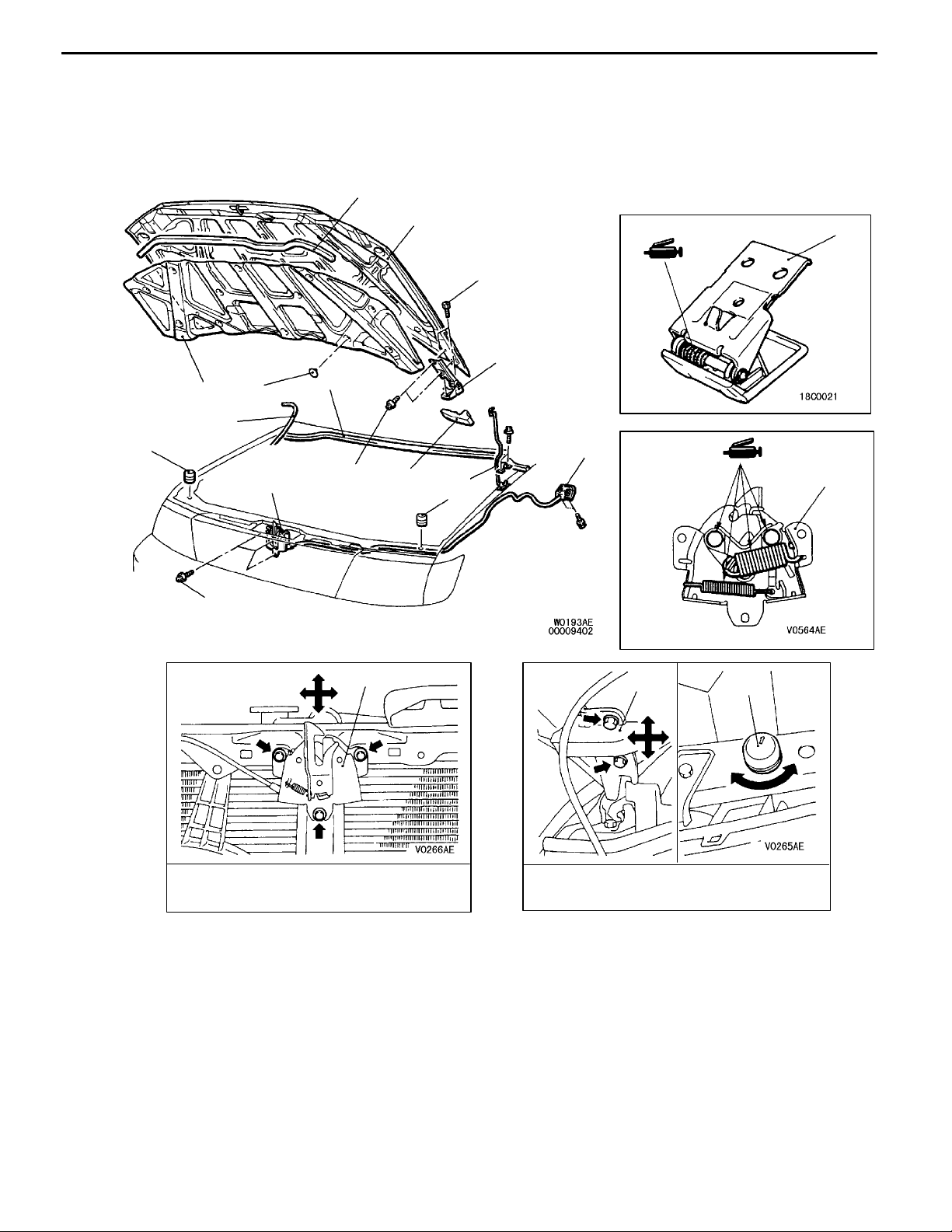
HOOD 42100160045
REMOVAL AND INSTALLATION
3
11
1
22 Nm
12
5
4
2
10
6
9
22 Nm
13
7
1
9
6
9Nm
9
Adjustment of hood step and
hood striker linkage
1. Hood lock release handle
2. Hood weatherstrip
3. Front hood weatherstrip
4. Clip
5. Hood insulator
6. Bumper
7. Hood support rod
Hood lock release cable removal
steps
8. Hood lock release cable
13
Adjustment of clearance around
hood and height
Hood latch removal steps
D Radiator grille (Refer to GROUP 51.)
9. Hood latch
Hood and hood hinge removal steps
10. Washer hose connection
1 1. Hood
12. Hood hinge
13. Hood side weatherstrip
6
Page 4
42-4
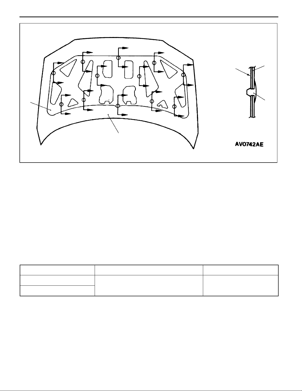
Clip positions
BODY -
Hood/Fender
A
A
A
A
A
A
A
A
A
A
A
A
A
A
A
A
A
A
A
5
A
A
A
A
A
Section A - A
Hood inner
panel
5
4
11
FENDER 42100050137
SEALANT
Item Specified sealant Remark
Splash shield 3M ATD Part No. 8625 or equivalent Ribbon sealer
Fender
Page 5
BODY -
Fender
42-5
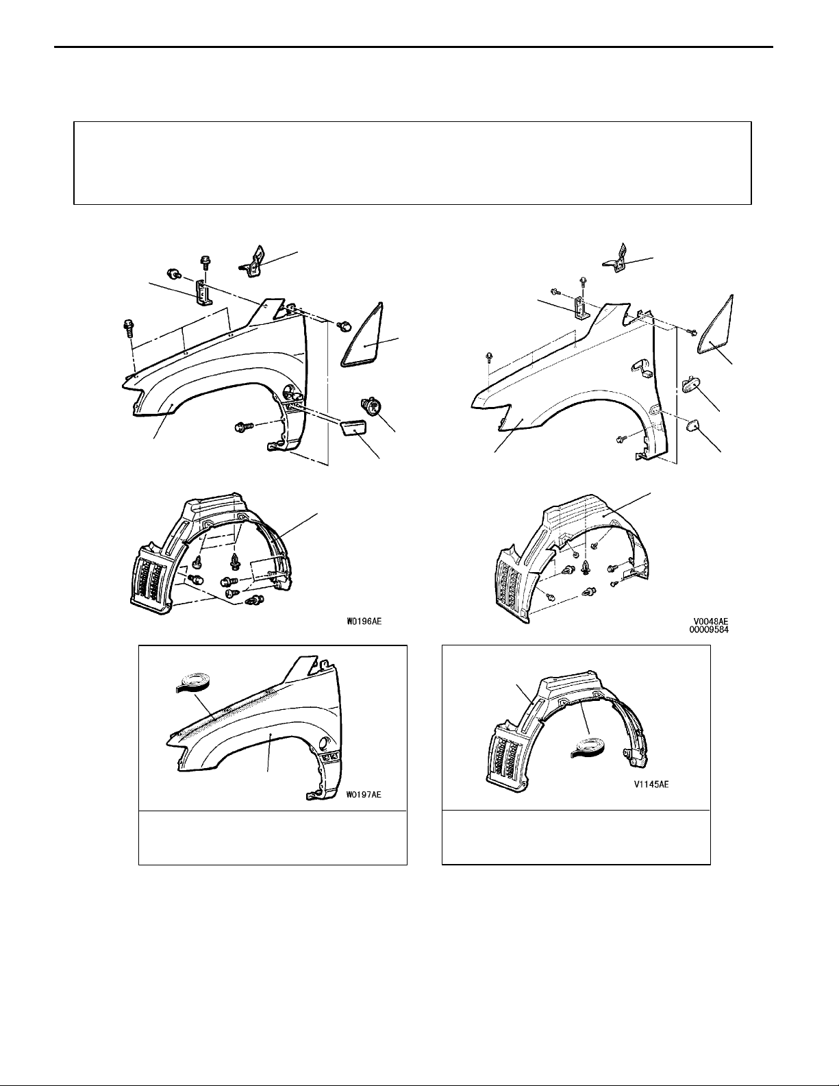
FENDER
REMOVAL AND INSTALLATION
Pre-removal and Post-installation Operation
D Front Bumper Removal and Installation
(Refer to GROUP 51.)
D Headlamp Removal and Installation
(Refer to GROUP 54.)
<SPACE RUNNER>
1
7
5
42100190204
D Side Sill Cover Removal and Installation (Refer to
GROUP 51 - Aero Parts.)
D Hood Removal and Installation (Refer to P.42-3.)
<SPACE WAGON>
1
7
2
2
4
4
6
5
6
3
5
Sealant:
3M ATD Part No. 8625 or
equivalent
3
3
Sealant:
3M ATD Part No. 8625 or
equivalent
AA""AA
Removal steps
1. Front fender cover
2. Delta garnish
(Refer to GROUP 51 - Garnish.)
3. Splash shield
4. Side turn signal lamp
5. Fender
6. Side moulting
(Refer to GROUP 51 - Mouldings.)
7. Fender bracket
Page 6
42-6
BODY -
Fender
Fender
Fender
Lock
Fender
Hook
Lock
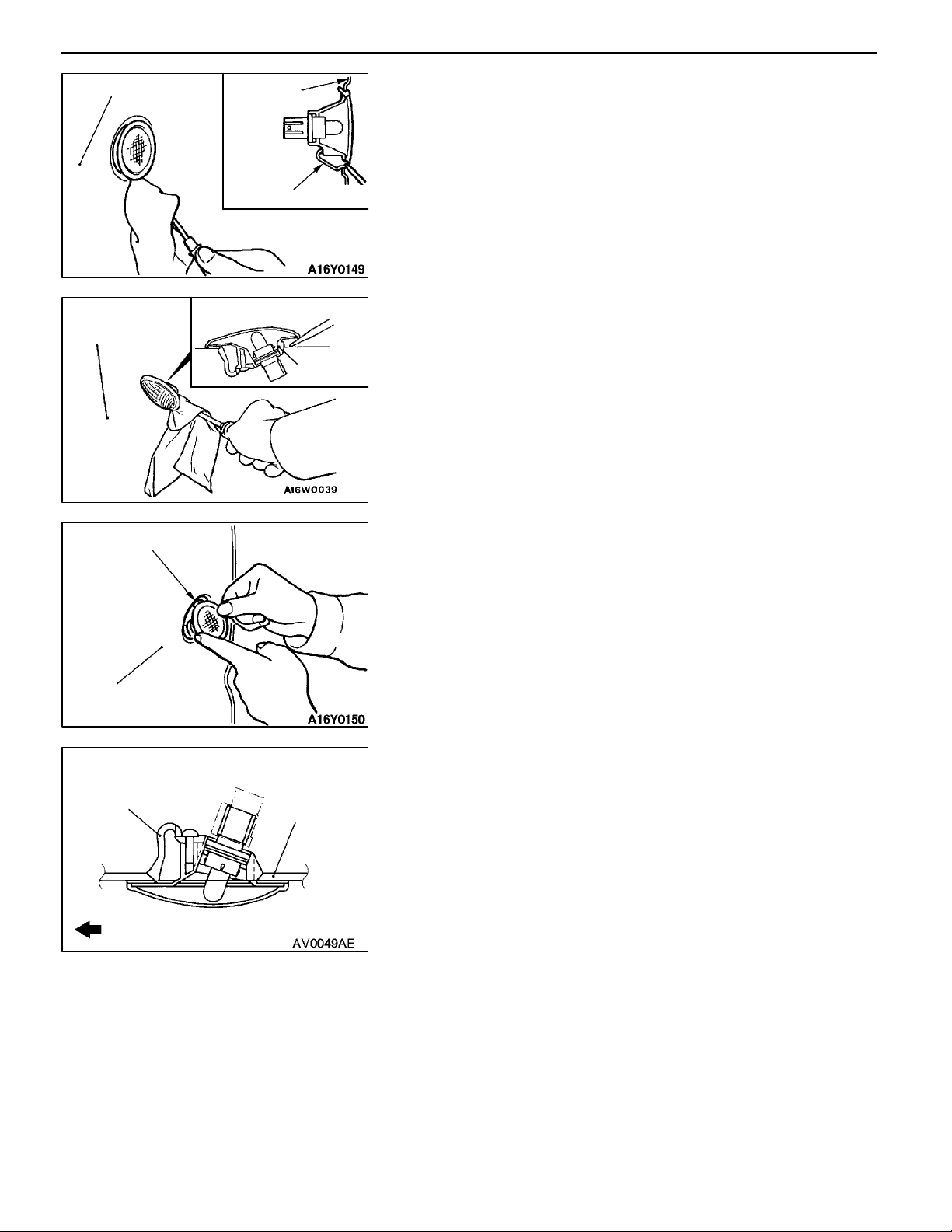
REMOVAL SERVICE POINT
AA"
<SPACE RUNNER>
Use a flat-tipped screwdriver to disengage the hook from
the fender, and then remove the side turn signal lamp.
<SPACE WAGON>
Use a flat-tipped screwdriver to disengage the lock from the
fender, and then remove the side turn signal lamp.
SIDE TURN SIGNAL LAMP REMOVAL
INSTALLATION SERVICE POINT
"AA
<SPACE RUNNER>
1. Put the lock in fender.
2. Push the side turn signal lamp toward the fender until
SIDE TURN SIGNAL LAMP INSTALLATION
the hook is caught in fender.
Fender
Hook
Front of vehicle
<SPACE WAGON>
Insert the hook into the fender panel, and then install the
side turn signal lamp.
Fender
Page 7
BODY -
Fuel Filler Door
42-7
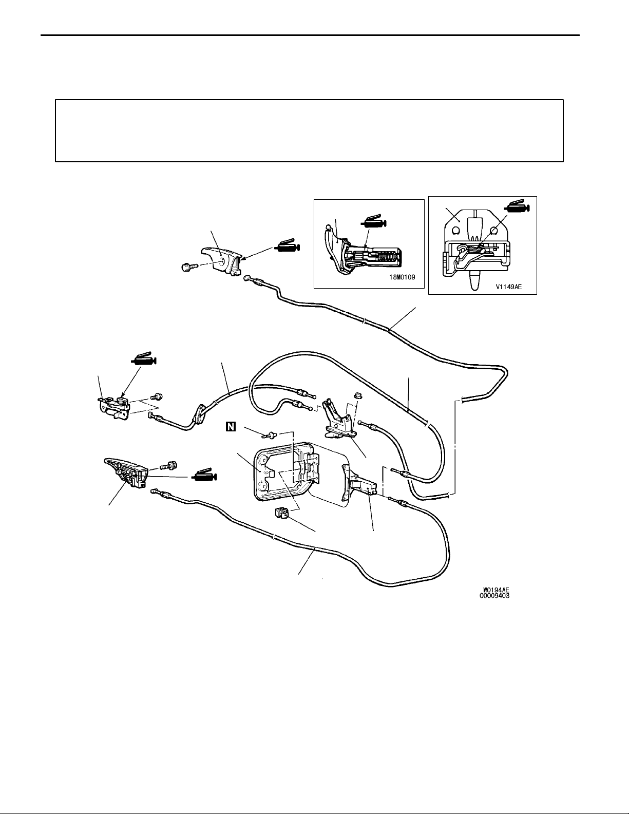
FUEL FILLER DOOR 42100250346
REMOVAL AND INSTALLATION
Pre-removal and Post-installation Operation
D Front Seat (driver’s side), Rear Seat Removal and
Installation (Refer to GROUP 52A.)
D Front Scuff Plate (driver’s side), Rear Scuff Plate
(driver’s side), Center Pillar Lower Trim (driver’s side),
<SPACE RUNNER>
Quarter Lower Trim (driver’s side) Removal an d
Installation (Refer to GROUP 52A.)
<R.H. drive vehicles>
10
<L.H. drive vehicles>
7
8
9
4
5
6
1
2
8
AA""AA
9
Removal steps
1. Rivet
2. Fuel filler door panel assembly
3. Clip
4. Fuel filler door lock release cable
5. Fuel filler door safety cable
6. Fuel filler door lock release cable
3
7
4
7. Fuel filler door hook assembly
8. Fuel filler door safety lever
assembly
9. Fuel filler door lock release handle
10. Fuel filler door safety stopper
assembly
Page 8
42-8
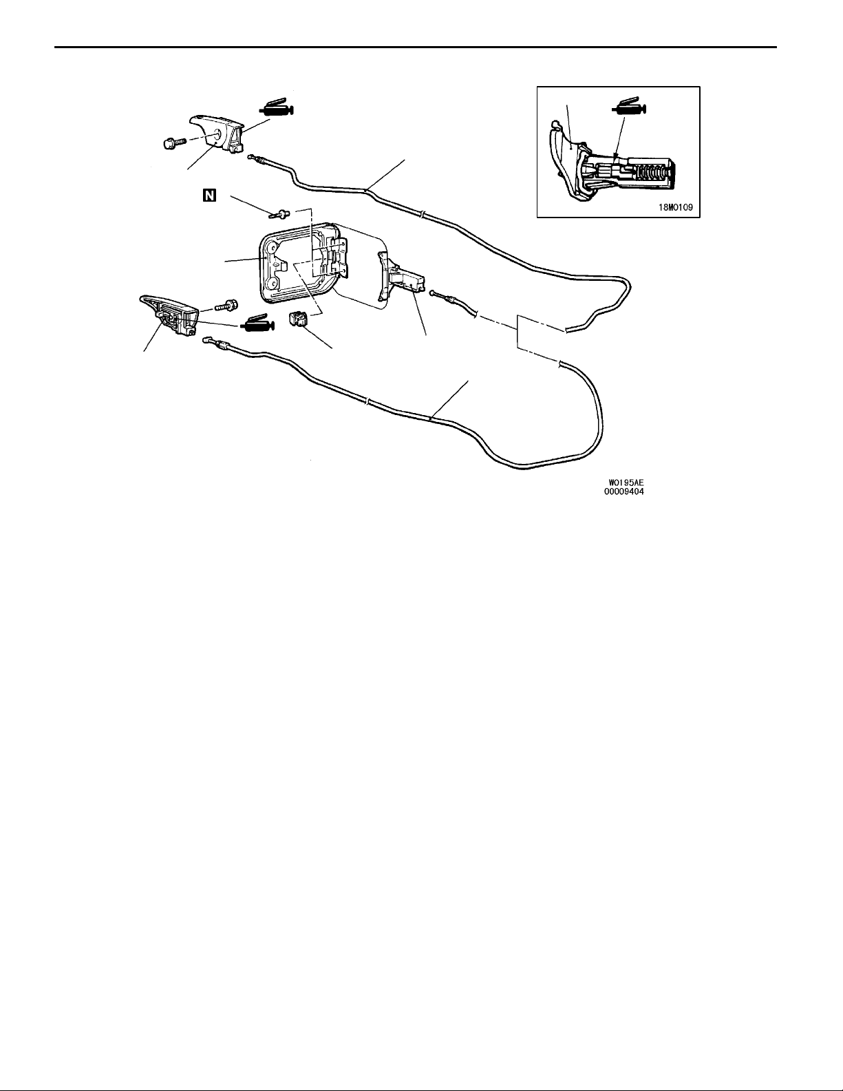
<SPACE WAGON>
<R.H. drive vehicles>
<L.H. drive vehicles>
BODY -
Fuel Filler Door
4
6
5
1
2
5
Removal steps
AA""AA 1. Rivet
2. Fuel filler door panel assembly
3. Clip
3
4
6
4. Fuel filler door hook assembly
5. Lid lock release handle
6. Fuel filler door lock release cable
Page 9
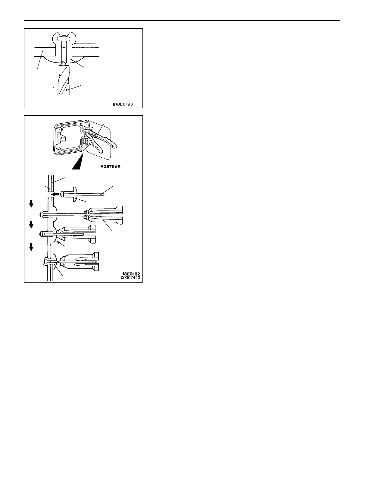
Fuel filler
door panel
assembly
Rivet
Drill
BODY -
REMOVAL SERVICE POINT
AA"
Use a drill (Ø4.0 - 5.5 mm) to break the rivet by drilling
a hole, and then remove the rivet.
Fuel Filler Door
RIVET REMOVAL
42-9
Body
panel
1
2
3
4
Fuel filler door
panel assembly
Rivet
Flange surface
Rivet
Riveter
A
Riveter
INSTALLATION SERVICE POINT
"AA
Use a riveter shown to install th e rivet by the following
procedure:
1. Insert the rivet into the body panel and fuel filler door
2. Insert “A” of the rivet into the riveter.
3. Pressing the flange surface of the rivet with the riveter,
4. The thinnest point of “A” is cut and the rivet is held in
RIVET INSTALLATION
panel assembly.
move the handle of the riveter.
the position.
Page 10
42-10
BODY -
Window Glass
WINDOW GLASS 42200050161
ADHESIVE
Items Specified adhesive
Windshield 3M ATD Part No. 8609 Super Fast Urethane Auto Glass
Sealant or equivalent
Quarter window glass
Slide door window glass
Tailgate window glass
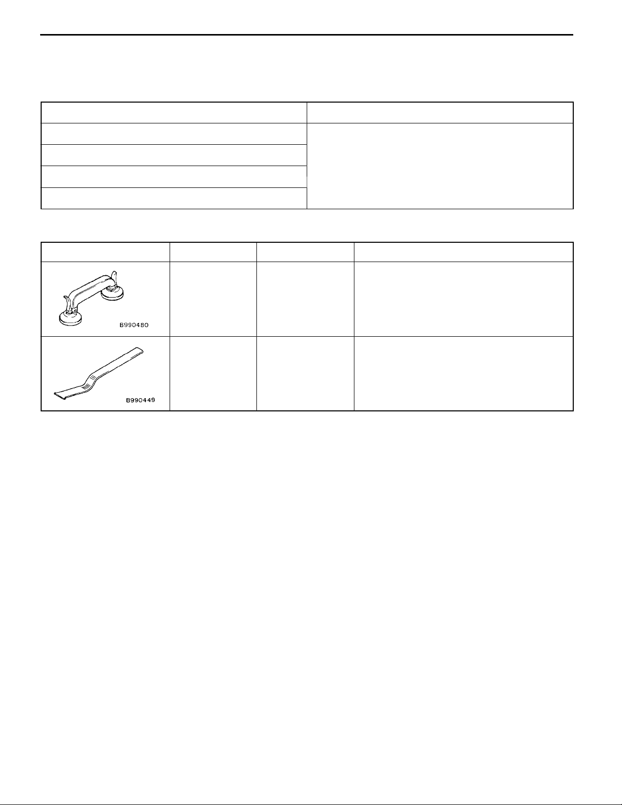
SPECIAL TOOLS
Tool Number Name Use
MB990480 Glass holder Removal and installation of windshield
MB990449 Window moulding
remover
WINDOW REPAIR
The following glass sections are installed by means of a liquid
urethane adhesive method.
Windshield
D
Quarter window glass
D
Slide door window glass
D
Tailgate window glass
D
42200060164
Removal of roof drip moulding
42200560114
Page 11

BODY -
Window Glass
42-11
ITEMS NEEDED
Name Remarks
Adhesive 3M ATD Part No. 8609 Super Fast Urethane Auto Glass Sealant or
equivalent
Primer 3M ATD Part No. 8608 Super Fast Urethane Primer or equivalent
Spacers Available as service part
Anti-rust solvent
(or Tectyl 506T...Valvoline Oil Company)
Isopropyl alcohol For grease removal from bonded surface
Steel piano wire Dia. ´ length...0.6mm ´ 1m For cutting adhesive
Adhesive gun For pressing-out adhesive
NOTE
The TEROSON 127.37V auto window sealer kit can also be used. If using the TEROSON 127.37V auto window
sealer kit, follow the instructions in the manual included with the kit.
For rust prevention
HANDLING OF AUTO WINDOW SEALER
Keep the sealant in a cool place, not exposed to the direct
rays of the sun. Do not place any heavy article on the sealant
nor press it, otherwise it will become deformed. Avoid storing
the sealant for more than 6 months, because it will lose its
sealing effect.
BODY PINCH-WELD FLANGE SERVICING.
Before servicing the body pinch-weld flange, remove old
adhesive completely. If the flange requires painting, bake
it after painting is completed.
Page 12
42-12
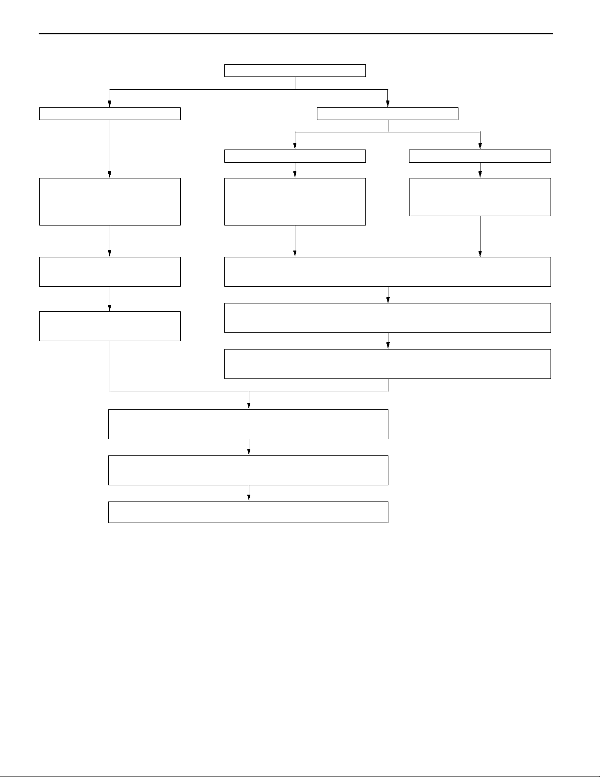
WORKING PROCESS
BODY -
Window glass installation procedure
Window Glass
Body side
Cleaning of adhesion surface
Cut off the residual adhesive until the
thickness is less than 2 mm. Clean the
adhesion surface with isopropyl alcohol,
and let dry for 3 minutes or more.
Attaching of clip
Attach the clip to set the positions for
the glass to be installed.
Application of primer
Apply to the adhesion surface of the
body and let dry for 3 minutes or more.
Window glass side
Reusing the glass Replacing the glass
Cleaning of adhesion surface
Completely cut off all of the residual
adhesive. Clean the adhesion surface
with isopropyl alcohol, and let dry for
3 minutes or more.
Gluing of window spacer and glass stoppers
Glue the window spacer along the standard position on the glass outer circumference. Install
the glass stoppers to the specified positions.
Application of primer
Apply sufficient primer evenly to the adhesion surface so that there is no patchiness. After
application, let dry for 3 to 30 minutes.
Application of adhesive
Within 30 minutes after applying the primer, apply the adhesive evenly all the way around
the inside edge of the glass.
Cleaning of adhesion surface
Clean off any dirt adhering to the adhesion surface with isopropyl alcohol, and
let dry for 3 minutes or more.
Installing the glass
After applying the adhesive, lightly press the glass evenly so that it adheres
completely.
Cleaning
After removing any adhesive that is sticking out or adhering to the body or
glass with a spatula, etc., clean off with isopropyl alcohol.
Checking for water leaks
Carry out a shower test to check that no water will leak through.
Page 13
BODY -
Window Glass
42-13
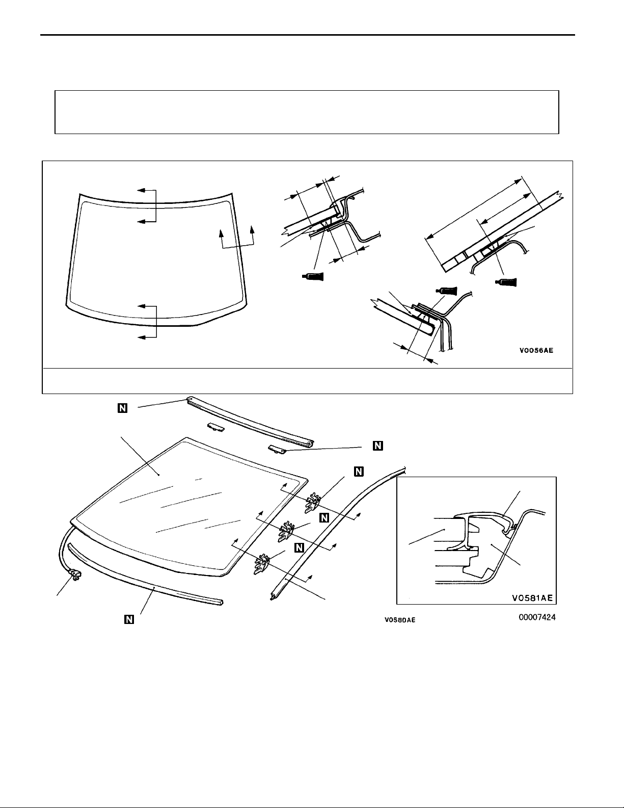
WINDSHIELD
REMOVAL AND INSTALLATION
Pre-removal and Post-installation Operation
D Front Pillar Trim Removal and Installation
(Refer to GROUP 52A.)
Section A - A
A
A
B
B
C
C
Primer
D Headlining Removal and Installation
2
16
9
Section C - C
Section B - B
Primer
61
42200100378
mm
37
Primer
11
Adhesive: 3M ATD Part No. 8609 Super Fast Urethane Auto Glass Sealant or equivalent
6
3
4
7
D
D
8
D
D
D
9
D
1
2
Section D - D
3
5
2
7, 8, 9
AA"
Removal steps
1. Wiper deicer <Vehicle for cold
climate region>
2. Roof drip moulding (Refer to
GROUP 51 - Moulding.)
D
Front deck garnish
(Refer to GROUP 51 - Windshield
Wiper and Washer.)
AB""AA
"AA
"AA
"AA
3. Windshield
4. Glass stopper
5. Window spacer
6. Windshield upper moulding
7. Drip moulding clip A
8. Drip moulding clip B
9. Drip moulding clip C
Page 14
42-14
MB990449
BODY -
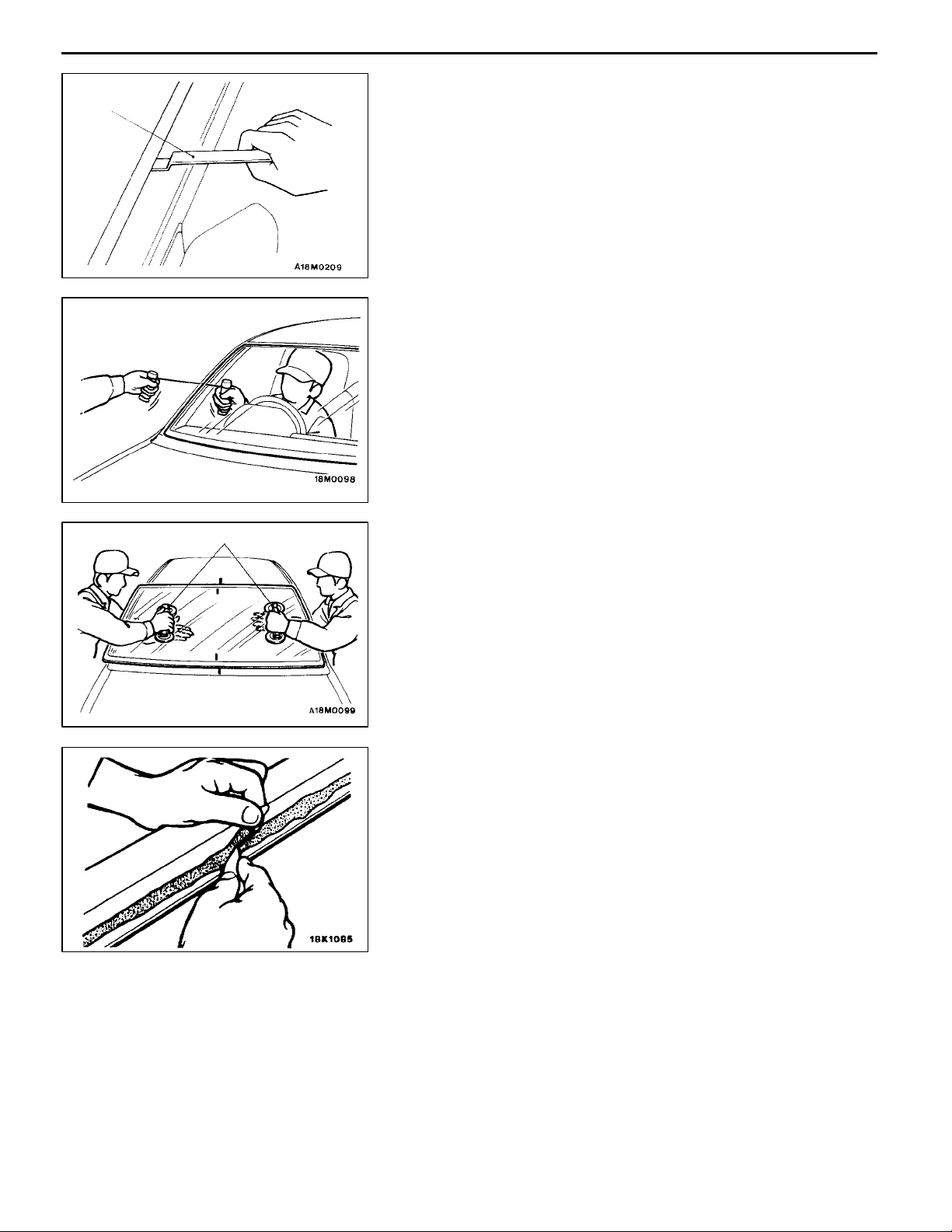
REMOVAL SERVICE POINTS
AA"
Use the special tool to lever out the moulding.
Caution
If the moulding has become warped, it should not be
reused.
Window Glass
ROOF DRIP MOULDING REMOVAL
MB990480
AB"
1. In order to protect the body (paint surface), apply cloth
2. Using a sharp-point drill, make hole in the windshield
3. Pass the piano wire from the inside of the vehicle through
4. Pull the piano wire alternately from the inside and outside
5. Make mating marks on the windshield and body.
6. Use the special tool to remove the windshield.
7. Use a knife to cut away the remaining adhesive so that
8. Finish the flange surfaces so that they are smooth.
WINDSHIELD REMOVAL
tape to all body areas around the installed windshield.
adhesive.
the hole.
along the windshield to cut the adhesive.
Caution
Do not let the piano wire touch the edge of the
windshield.
the thickness is within 2 mm around the entire
circumference of the body flange.
Caution
(1) Be careful not to remove more adhesive than is
necessary.
(2) Be careful also not to damage the paintwork on
the body surface with the knife. If the paintwork
is damaged, repair the damaged area with repair
paint or anti-rust agent.
9. When reusing the windshield, remove the adhesive still
adhering to the windshield, and clean with isopropyl
alcohol.
10. Clean the body side in the same way.
Caution
Let the cleaned places stand for 3 minutes or more,
and carry out the next procedures after they have
dried. Also, do not touch any surface that has been
cleaned.
Page 15
BODY -
Window Glass
42-15
A
300 mm
A
Section A - A
19.6 mm
Glass stopper
10 mm
15 mm
Centre
Glass stopper
300 mm
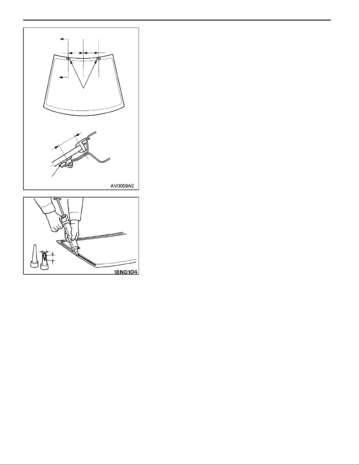
INSTALLATION SERVICE POINTS
"AA
1. When replacing the windshield, temporarily set the
2. Use isopropyl alcohol to degrease the inside and outside
3. Soak a sponge in the primer, and apply evenly to the
4. Apply the primer, and then let it dry for 3 to 30 minutes.
5. Install the windshield upper moulding to the windshield.
6. Place the window spacer to the windshield so that it
7. Install the glass stopper to the shown dimension.
8. Fill a sealant g u n with adhesive. Then apply the adhesive
9. After applying the adhesive, align the mating marks on
10. Use a spatula or the like to remove any excessive
11. Try not to move the vehicle until the adhesive sets. Wait
WINDSHIELD UPPER MOULDING/WINDOW
SPACER/GLASS STOPPER/WINDSHIELD
INSTALLATION
windshield against the body, and place a mating mark
on the windshield and body.
of the windshield and the body flanges.
windshield and the body in the specified places.
Caution
(1) The primer strengthens the adhesive, so be sure
to apply it evenly around the entire circumference.
However, a too thick application will weaken the
adhesive.
(2) Do not touch the coated surface.
inclines toward t he windshield and its right and left
clearances are equal. Then install the spacer firmly so
that it is not adrift.
evenly around the windshield within 30 minutes after
applying the primer.
NOTE
Cut the tip of the sealant gun nozzle into a V shape
to simplify adhesive application.
the windshield and the body, and then press the windshield
gently to seat it.
adhesive. Then clean the surface with isopropyl alcohol.
Install the roof drip moulding before the adhesive hardens.
30 minutes or more, and then test for water leakage.
Caution
(1) Do not move the vehicle unless absolutely
necessary.
(2) When testing for water leakage, do not pinch the
end of the hose to spray the water.
Page 16
42-16
BODY -
Window Glass
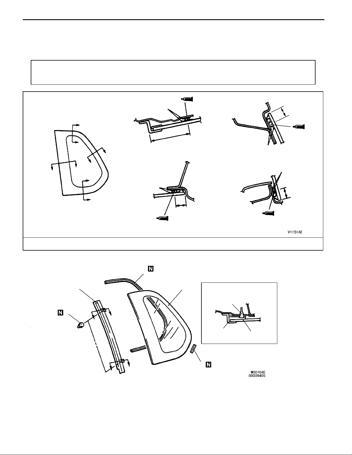
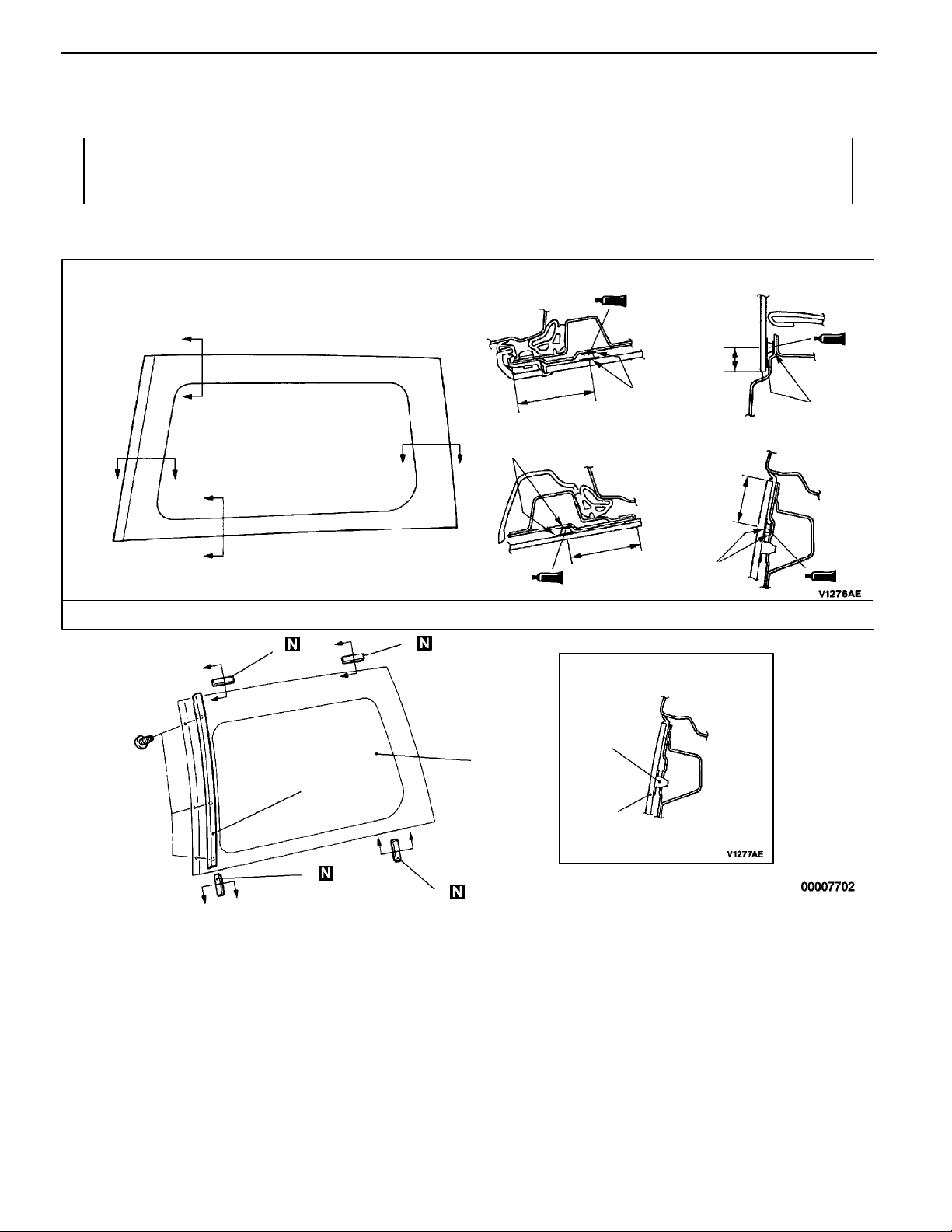
QUARTER WINDOW GLASS
REMOVAL AND INSTALLATION
<SPACE RUNNER>
Pre-removal and Post-installation Operation
D Quarter Upper Trim Removal and Installation
(Refer to GROUP 52A.)
Section A - A
B
B
C
C
A
A
D
D
Section C - C
Primer
Primer
D Headlining Removal and Installation
Section B - B
57
Section D - D
42200250196
mm
14.5
Primer
Primer
14.5
14.5
Adhesive: 3M ATD Part No. 8609 Super Fast Urethane Auto Glass Sealant or equivalent
1
3
2
Section E - E
4
4
E
E
3
E
E
5
2
AA""AA
AA""AA
AA""AA
Removal steps
1. Quarter window dam
2. Quarter window glass
3. Quarter window garnish
"AA
4. Clip A
5. Spacer
Page 17
BODY -
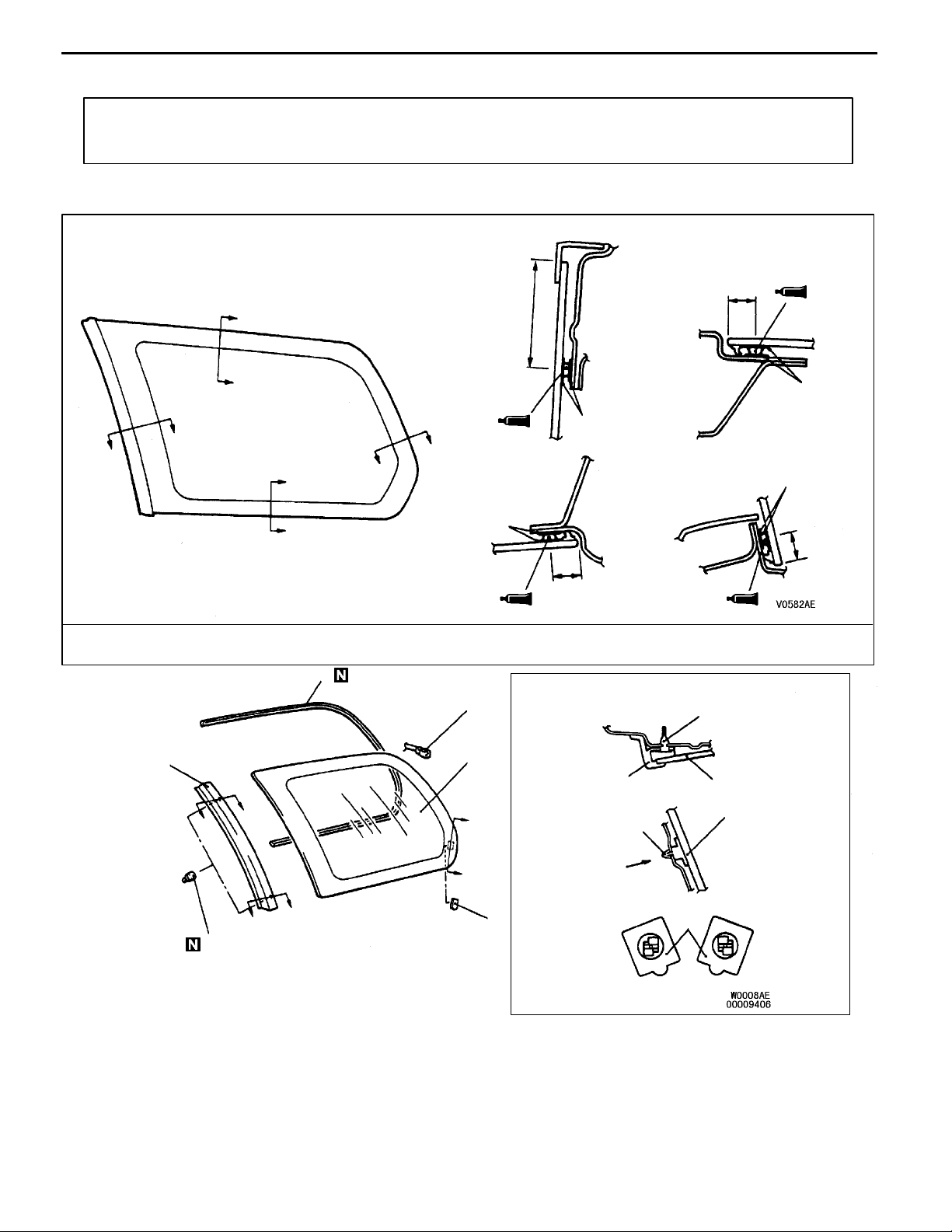
<SPACE WAGON>
Pre-removal and Post-installation Operation
D Quarter Upper Trim, Retractor Trim and Belt Line Trim
Removal and Installation (Refer to GROUP 52A.)
Window Glass
D Headlining Removal and Installation
42-17
Section A - A
Section B - B
14.5
B
B
A
A
D
D
C
C
Section C - C
55
Primer
Section D - D
Primer
14.5
Adhesive: 3M ATD Part No. 8609 Super Fast Urethane Auto Glass Sealant or equivalent
2
1
Section E - E
6
mm
Primer
Primer
14.5
AA""AA
AA""AA
5
E
E
E
E
6
Removal steps
1. Harness connector
2. Quarter window dam
3. Quarter window glass
3
Section F - F
F
F
View G
4
AA""AA
View G
For left window glass
"AA
5
3
3
4
4
For right
window glass
4. Clip B
5. Quarter window garnish
6. Clip A
Page 18
42-18
BODY -
REMOVAL SERVICE POINT
AA"
<SPACE RUNNER>
Removal procedure is same as for the windshield except
for the service points mentioned below. (Refer to P.42-14.)
(1) Break a clip A to remove it.
(2) If the quarter window glass or quarter window garnish
<SPACE WAGON>
Removal procedure is same as for the windshield except
for the service points mentioned below. (Refer to P.42-14.)
(1) Break the clip A to remove it.
(2) Use pliers to pinch the clip B behind the quarter window
(3) If the quarter window glass or quarter window garnish
Window Glass
QUARTER WINDOW DAM/QUARTER WINDOW
GLASS/QUARTER WINDOW GARNISH REMOVAL
is re-used, make the positioning mark on it before removing
in order to re-install it correctly.
garnish to remove it.
is re-used, make the positioning mark on it before removing
in order to re-install it correctly.
Position A
Position B
Positioning
mark
INSTALLATION SERVICE POINT
"AA
Installation procedure is same as for the windshield except
for the service points mentioned below. (Refer to P.42-14.)
If the quarter window glass or quarter window garnish is
re-used, install it by the following procedure:
1. If t he quarter window garnish is re-used, cut away the
2. If the quarter window glass is re-used and the clip B
3. If the quarter window glass is re-used, eliminate the clip
4. Assemble the quarter window glass and quarter window
QUARTER WINDOW GARNISH/CLIP A/QUARTER
WINDOW GLASS/QUARTER WINDOW DAM
INSTALLATION
remaining clips at positions A and B, and clean up the
clip surface .
NOTE
If the quarter window garnish is re-used, you made the
positioning mark, therefore you may eliminate the clips.
had been broken, make the positioning mark as shown
in the illustration before eliminating the clip B, in order
to install new clip B correctly.
B which was broken, and then attach new clip B at the
marked position by using the double-sided tape. Clips
B for left window glass and right window glass differ in
shape, therefore confirm its shape before attaching.
garnish temporarily, and note their contact surfaces.
Page 19
BODY -
5. Disassemble the quarter window glass and quarter
6. If the quarter window garnish is re-used, apply a butyl
7. If the quarter window garnish is re-used, apply an adhesive
8. Install the quarter window glass and quarter window
Window Glass
42-19
window garnish, and degrease that contact surfaces in the
same manner as for the windshield. Apply primer and
adhesive to the contact surfaces, and then assemble
them.
tape to the clip fixing bosses on the quarter window garnish
at positions A and B, in order to prevent the noise.
tape to the clip holes on the body panel at positions
A and B, in order to prevent water from penetrating.
garnish to the body, and use a gummed tape, etc. to
fix them until the adhesive hardens.
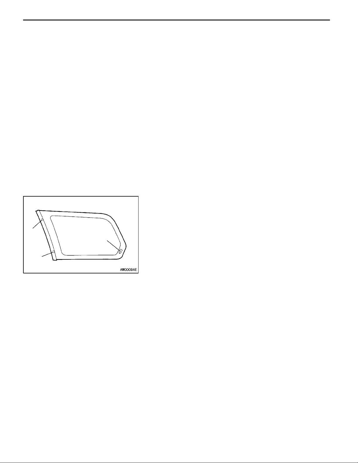
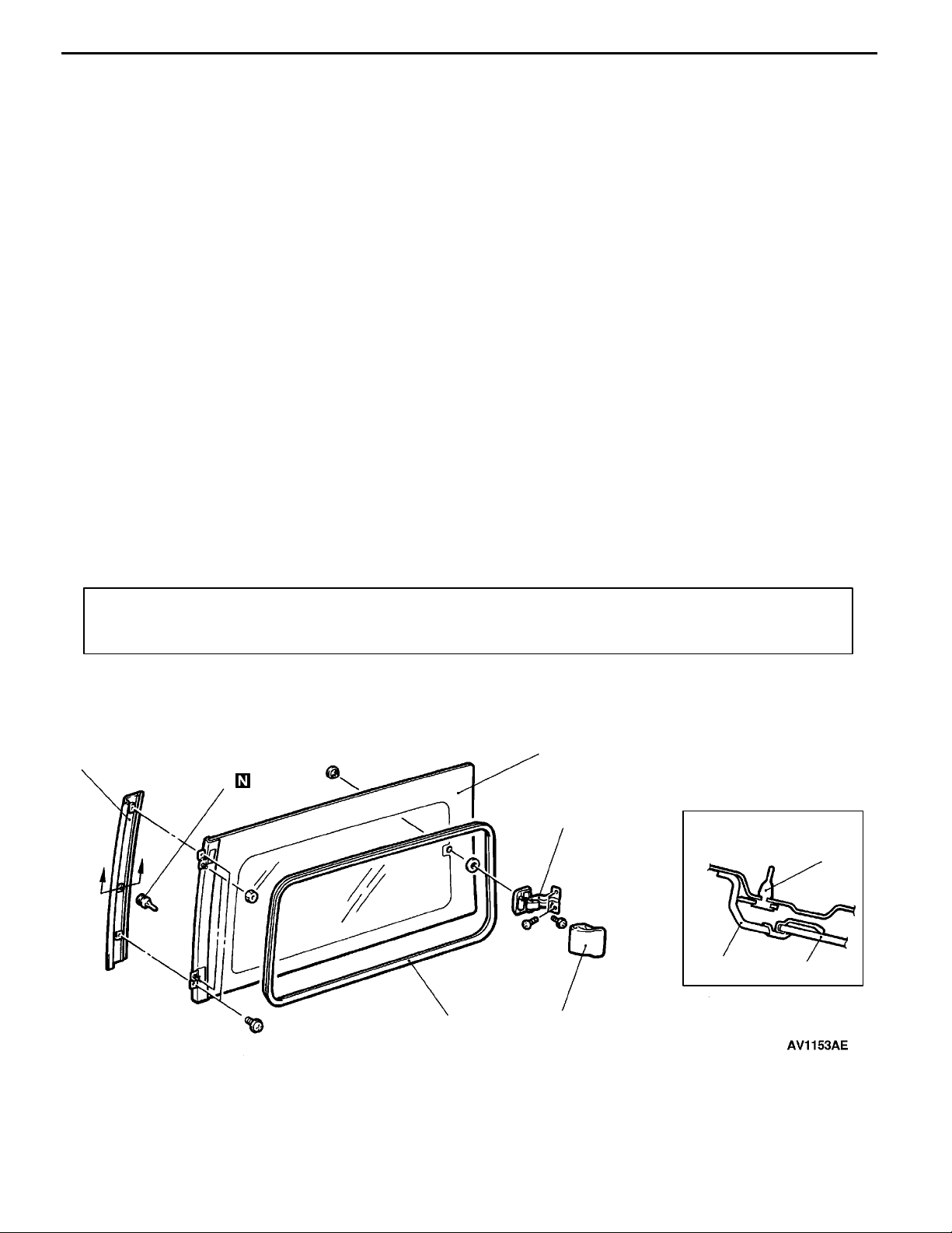
SIDE WINDOW GLASS <SPACE RUNNER>
REMOVAL AND INSTALLATION
Pre-removal and Post-installation Operation
Quarter Upper Trim Removal and Installation
D
(Refer to GROUP 52A.)
4
5
A
A
Headlining Removal and Installation
D
3
42200250196
2
Section A - A
5
4
3
Removal steps
1. Link cover
2. Side window link assembly
3. Side window glass
6
1
4. Side window glass moulding
5. Clip
6. Side window weatherstrip
Page 20
42-20
BODY -
Window Glass
SLIDE DOOR WINDOW GLASS <SPACE RUNNER>
REMOVAL AND INSTALLATION
Pre-removal and Post-installation Operation
D Slide Door Sash Trim Removal and Installation
(Refer to P.42-59.)
D
D
A
A
B
CC
D Slide Door Upper Trim Removal and Installation
(Refer to P.42-59.)
Section A - A
51.0
Section C - C
Primer
Primer
Section D - D
Section B - B
15.5
31.0
42200250196
mm
Primer
B
46.5
Primer
Adhesive: 3M ATD Part No. 8609 Super Fast Urethane Auto Glass Sealant or equivalent
3
E
E
E
E
3
Section E - E
3
2
1
2
E
E
3
3
3. Glass stopper
AA""AA
E
E
Removal steps
1. Slide door window garnish
2. Slide door window glass assembly
Page 21

BODY -
REMOVAL SERVICE POINT
AA"
Remove the slide door window glass assembly in the same
manner as for the windshield, except th e glass stopper. (Refer
to P.42-14.)
INSTALLATION SERVICE POINT
"AA
Install the slide door window glass assembly in the same
manner as for the windshield, except th e glass stopper. (Refer
to P.42-15.)
Window Glass
SLIDE DOOR WINDOW GLASS ASSEMBLY
REMOVAL
SLIDE DOOR WINDOW GLASS ASSEMBLY
INSTALLATION
42-21
Page 22
42-22
BODY -
Window Glass
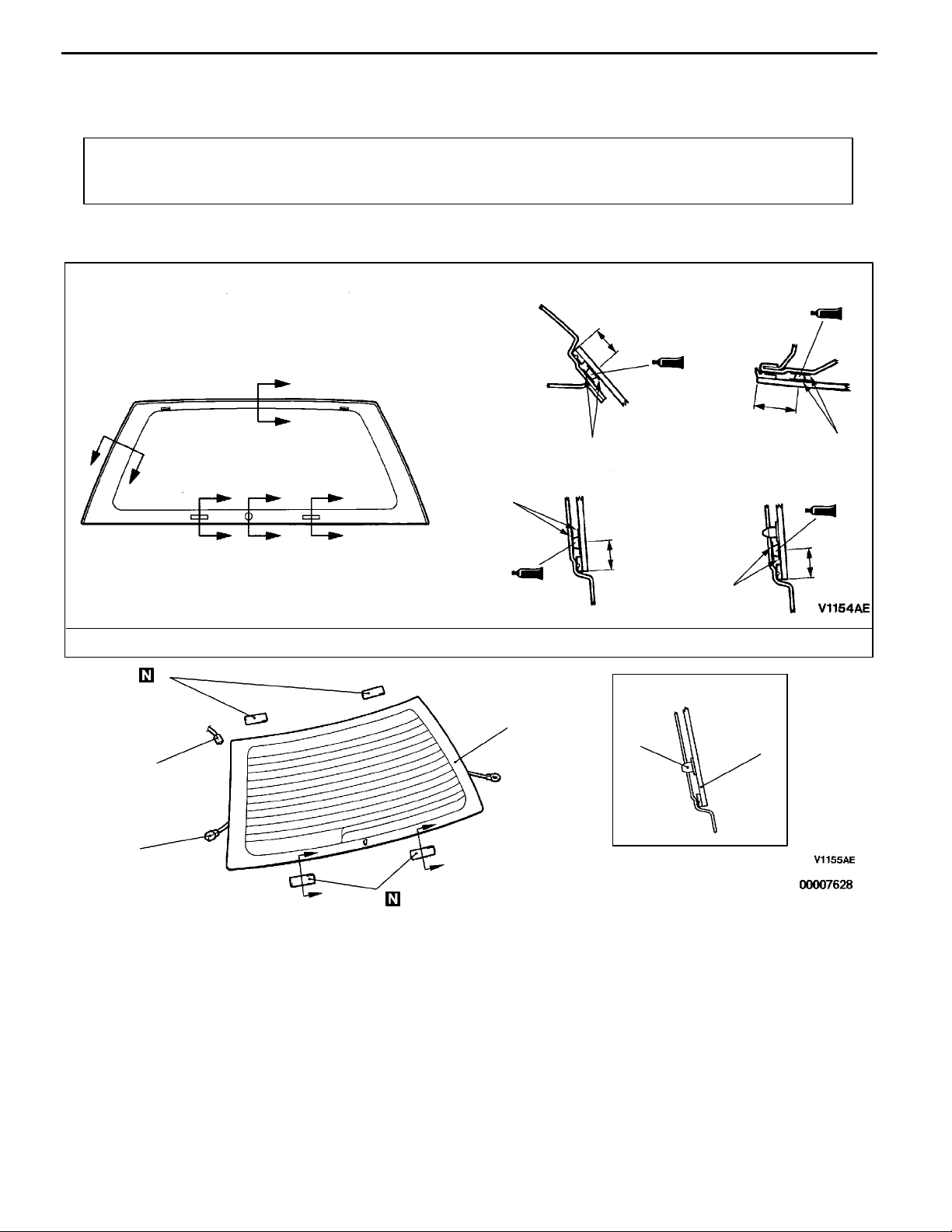
TAILGATE WINDOW GLASS
REMOVAL AND INSTALLATION
Pre-removal and Post-installation Operation
D Side Tailgate Trim, Lower Tailgate Trim Removal and
Installation (Refer to P.42-67.)
<SPACE RUNNER>
A
A
B
B
D
D
C
C
D
D
D Rear Wiper Removal and Installation
(Refer to GROUP 51.)
Section A - A
18.5
Primer
Section C - C
Primer
18.5
Section B - B
Section D - D
42200370243
mm
28.5
Primer
18.5
Primer
Adhesive: 3M ATD Part No. 8609 Super Fast Urethane Auto Glass Sealant or equivalent
5
Section E - E
3
4
2
E
1
Removal steps
1. Harness connector
2. Harness connector <Vehicles with
diversity antenna>
E
E
E
4
AA""AA
3. Tailgate window glass
4. Glass stopper
5. Dual-lock fastener
3
Page 23
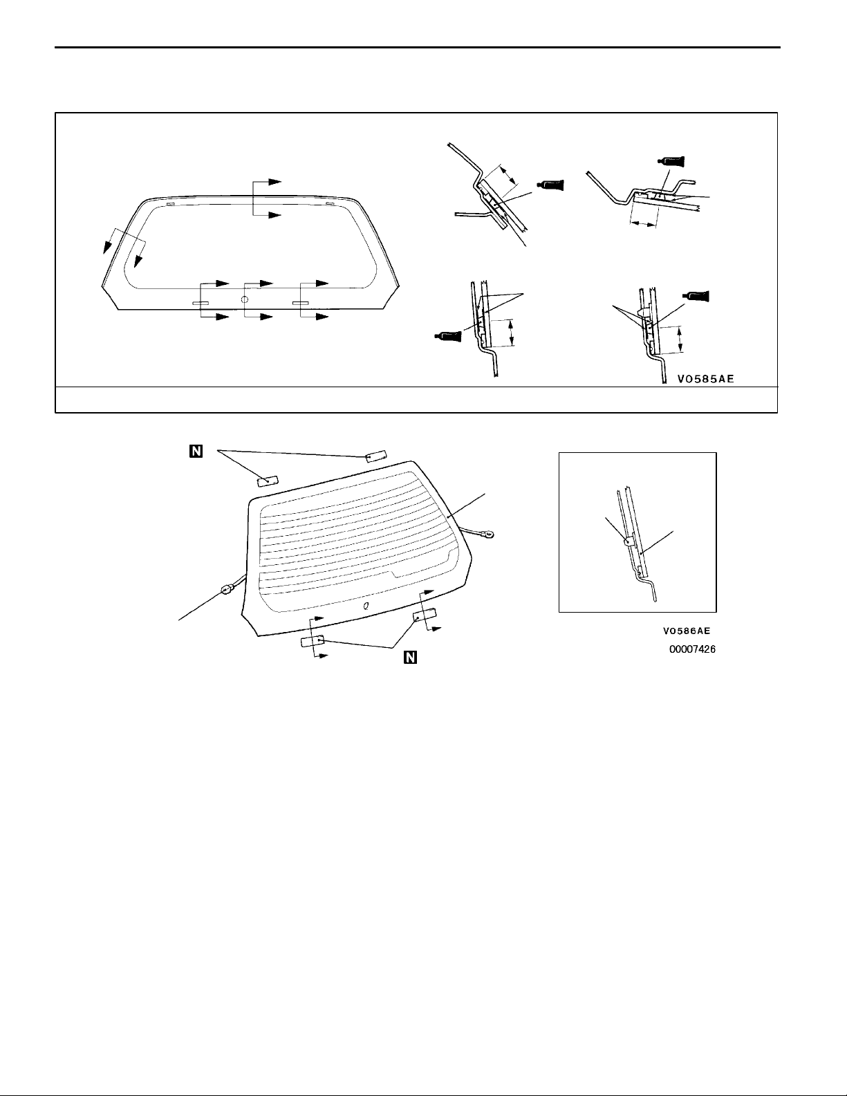
<SPACE WAGON>
BODY -
Window Glass
42-23
Section A - A
A
A
B
B
D
D
C
C
D
D
Section C - C
18.5
Primer
Primer
18.5
Section B - B
18.5
Section D - D
Primer
Adhesive: 3M ATD Part No. 8609 Super Fast Urethane Auto Glass Sealant or equivalent
3
Section E - E
2
3
mm
Primer
18.5
2
AA""AA
1
Removal steps
1. Harness connector
2. Tailgate window glass
3. Glass stopper
E
E
E
3
E
REMOVAL SERVICE POINT
AA"
Remove the tailgate window glass in the same manner as
for the windshield, except the glass stopper. (Refer to P.42-14.)
TAILGATE WINDOW GLASS REMOVAL
INSTALLATION SERVICE POINT
"AA
Install the tailgate window glass in the same manner as for
the windshield, except the glass stopper. (Refer to P.42-15.)
TAILGATE WINDOW GLASS INSTALLATION
Page 24
42-24
BODY -
Door
DOOR 42300030168
SERVICE SPECIFICATIONS
Items Standard value
Door outside handle play mm Front <SPACE RUNNER> 2.1 or more
<SPACE WAGON> 1.9 or more
Rear 2.4 or more
Power window operating current A 5 ± 1 (for 14 -15 V power supply at 25_C)
Door inside handle play mm 5.3 or more
SEALANT
Items Specified sealant Remark
Waterproof film 3M ATD Part No. 8625 or equivalent Ribbon sealer
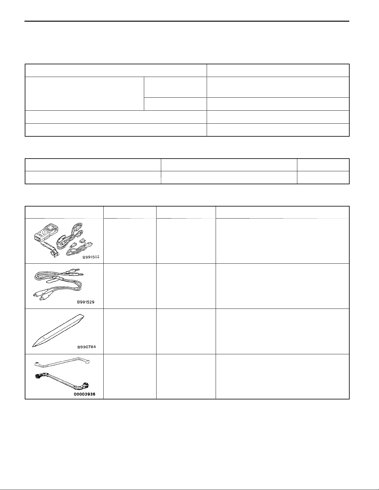
SPECIAL TOOLS
Tool Number Name Use
MB991502 MUT-II sub
assembly
MB991529 Diagnosis code
check harness
MB990784 Ornament remover Removal of door trim
ETACS-ECU input signal checking
ETACS-ECU input signal checking when
voltmeter is used
42300050065
42300060143
MB990900 or
MB991 164
Door adjusting
wrench
Adjustment of door fit
Page 25

BODY -
Door
42-25
TROUBLESHOOTING
42300070238
DIAGNOSIS FUNCTION
INPUT SIGNAL INSPECTION POINTS <VEHICLES WITH ETACS-ECU>
1. Connect the MUT-II to the diagnosis connector. (Refer to GROUP 00 - How to Use
Troubleshooting/Inspection Service Points.)
2. If buzzer of the MUT-II sounds once when door lock actuator switch is operated (LOCK/UNLOCK),
the ETACS-ECU input signal for that switch circuit system is normal.
INSPECTION CHART FOR TROUBLE SYMPTOMS
Trouble symptom Inspection
procedure
Power windows The power windows cannot be operated by any of the power
window switches.
Driver’s side power window cannot be operated by the power
window main switch.
Passenger’s side power window cannot be operated by the power
window main switch. (However, it can be operated by the power
window sub-switch.)
When the glass is raised, it then lowers automatically. 4 42-28
The glass is not lowered when something is jammed in the
window.
1 42-26
2 42-27
3 42-28
5 42-28
Reference
page
42300700083
Door locking
mechanism
When the glass is fully raised, it then lowers automatically. 6 42-29
None of the door lock functions operate. (Keyless entry system
does not operate also.)
None of the doors lock or unlock when the driver’s side inside door
locking knob is operated (including by means of the door key).
(However, keyless entry system operates.)
Some doors do not lock or unlock. 9 42-30
7 42-29
8 42-30
Page 26
42-26
BODY -
Door
INSPECTION PROCEDURE FOR TROUBLE SYMPTOMS
Inspection Procedure 1
The power windows cannot be operated by any of the
power window switches.
The cause may be a malfunction of the power window relay, power window relay
drive circuit and of the ETACS-ECU.
Check the power window relay continuity. (Refer to P.42-48.)
OK
Measure at the junction block connector
B-89.
D Disconnect the connector and
measure at the harness side.
D Ignition switch: ON and OFF
D Voltage between 1 and body earth
OK:
System voltage (ON)
0 V (OFF)
OK
Measure at the ETACS-ECU connector
B-104.
D Disconnect the connector and
measure at the harness side.
D Voltage between 8 and body earth
OK:
System voltage
OK
Replace the ETACS-ECU.
NG
NG
NG
Replace
Check the following connectors:
B-66, B-103, B-101, B-89
OK
Check trouble symptoms.
Check the following connectors:
B-104, B-101
OK
Check trouble symptoms.
Probable cause
D Malfunction of power window relay
D Malfunction of ETACS-ECU
D Malfunction of wiring harness or connector
NG
NG
NG
NG
Repair
Check the harness wire between fusible
link No.6 and power window relay, between power window relay and junction
block, and repair if necessary.
Repair
Check the harness wire between power
window relay and ETACS-ECU, and repair if necessary.
Page 27

Inspection Procedure 2
BODY -
Door
42-27
Driver’s side power window cannot be operated by the
power window main switch.
The cause may be a malfunction of power window main switch, power window
motor-ECU, or open circuit or short circuit in the communication line between power
window main switch and power window motor-ECU.
Measure at the power window main
switch connector D-17*, D-05*
D Disconnect the connector and
measure at the harness side.
D Ignition switch: ON and OFF
D Voltage between 3 <SPACE
RUNNER> or 1 <SPACE WAGON>
and body earth
OK:
System voltage (ON)
D Continuity between 5 <SPACE
Measure at the power window motorECU connector D-04*, D-15*
D Disconnect the connector and
D Ignition switch: ON and OFF
D Voltage between 1 and body earth
D Continuity between 3 and body earth
Measure at the power window main
switch connector D-17*, D-05*
power window motor-ECU connector
D-04*, D-15*
D Disconnect the connector and
D Continuity between 3 <SPACE
Replace the power window main switch.
0 V (OFF)
RUNNER> or 3 <SPACE WAGON>
and body earth
OK:
Continuity
OK
measure at the harness side.
OK:
System voltage (ON)
0 V (OFF)
OK:
Continuity
OK
1
.
measure at the harness side.
RUNNER> or 1 <SPACE WAGON>
(power window main switch side)
and 2 (power window motor-ECU
side)
OK:
Continuity
OK
1
.
1
.
1
and the
NG
NG
NG
Check the following connectors:
B-89, B-26, D-17*, D-05*
Check trouble symptoms.
Check the following connectors:
D-04*, D-15*
Check trouble symptoms.
Check the following connectors:
D-04*, D-17*, D-05*
Check trouble symptoms.
1
, B-66, B-89
OK
OK
1
, D-15*
OK
1
Probable cause
D Malfunction of power window main switch
D Malfunction of power window motor-ECU
D Malfunction of wiring harness or connector
NG
NG
NG
NG
NG
1
NG
Repair
Check the harness wire between junction block and power window main
switch, between power window main
switch and earth, and repair if necessary.
Replace the power window main switch.
Repair
Check the harness wire between junction block and power window motorECU, and repair if necessary.
Replace the power window motor-ECU.
Repair
Check the harness wire between power
window main switch and power window
motor-ECU, and repair if necessary.
OK
OK
*: L.H. drive vehicles
1
: R.H. drive vehicles
*
Page 28

42-28
Inspection Procedure 3
BODY -
Door
Passenger’s side power window cannot be operated by
the power window main switch. (However, it can be
operated by the power window sub-switch.)
The cause may be open circuit or short circuit in the communication line between
power window main switch and passenger’s side power window motor-ECU, or a
malfunction of power window main switch.
Measure at the connector B-26.
D Ignition switch: ON and OFF
D Voltage between 31 and body earth
OK:
System voltage (ON)
0 V (OFF)
OK
Check the following connectors:
B-66, D-04*, D-15*
Check trouble symptoms.
*: L.H. drive vehicles
1
*
: R.H. drive vehicles
1
OK
NG
NG
NG
Check the following connectors:
B-26, D-17*, D-05*
Check trouble symptoms.
Repair
Check the harness wire between connector B-26 and passenger’s side power
window motor-ECU, and repair if necessary.
1
OK
Probable cause
D Malfunction of wiring harness or connector
D Malfunction of power window main switch
NG
NG
Repair
Check the harness wire between power
window main switch and connector
B-16, and repair if necessary.
OK
Replace the power window main switch.
Inspection Procedure 4
When the glass is raised, it then lowers automatically.
If the sliding resistance is too large when the glass is being raised, it is judged that
something is jammed in the window, and the window is lowered by approximately
150 mm.
NG
Check the power window drive circuit. (Refer to P.42-33.)
Drive current: 5 ± 1A
OK
Replace the power window motor-ECU.
Inspection Procedure 5
Theglassis notlowered when something isjammed in the
window.
The cause may be a malfunction of the revolution detection sensor in the power
window motor-ECU.
Replace the power window motor-ECU.
Probable cause
D Incorrect window glass adjustment
D Glass slider is incorrectly installed or warped
Adjust the window glass. (Refer to P.42-31.)
Check trouble symptoms.
NG
Replace the window regulator assembly.
Probable cause
D Malfunction of power window motor-ECU
Page 29

Inspection Procedure 6
BODY -
Door
42-29
When the glass is fully raised, it then lowers
automatically.
When the window is within 15 mm of being fully closed, the limit switch turns off
to prevent the window from being lowered. However, the above problem can occur
if there is a malfunction of the limit switch in the power window motor-ECU.
Limit switch operation position adjustment (Refer to P.42-47.)
Check trouble symptoms.
NG
Replace the power window motor-ECU.
Inspection Procedure 7
None of the door lock functions operate. (Keyless entry
system does not operate also.)
The cause may be a malfunction of the ETACS-ECU power supply circuit system
or of the earth circuit system.
Measure at the junction block connector
B-104.
D Remove the ETACS-ECU and
measure at the junction block side.
D Voltage between 6 and body earth
OK:
System voltage
OK
Check the following connectors:
B-104, B-106, B-90
OK
Check trouble symptoms.
NG
NG
NG
Check the following connectors:
B-66, B-103, B-104
OK
Check trouble symptoms.
Repair
Check the harness wire between
ETACS-ECU and body earth.
OK
Probable cause
D Malfunction of the power window motor-ECU
Probable cause
D Malfunction of ETACS-ECU
D Malfunction of wiring harness or connector
NG
NG
NG
Repair
Check the harness wire between fusible
link No.5 and junction block, and repair
if necessary.
Repair
Replace the ETACS-ECU.
Page 30

42-30
Inspection Procedure 8
BODY -
Door
None of the doors lock or unlock when the driver’s-side
inside door locking knob is operated (including by means
of the door key). (However, keyless entry system
operates.)
The cause may be a malfunction of the door lock actuator switch, the ETACS-ECU
or of a wiring harness or connector.
MUT-IIPulse check
Front door lock actuator switch input
signal
OK:
The MUT-II buzzer sounds once
when the front door lock actuator
moves from the locked to the unlocked position, or from the unlocked to the locked position.
OK
Replace the ETACS-ECU.
*: L.H. drive vehicles
1
*
: R.H. drive vehicles
NG
Check the front door lock actuator.
(Refer to P.42-50.)
OK
Check the following connectors:
B-26, D-19*, D-08*
Check trouble symptoms.
1
, B-90, B-104, B-106
OK
Inspection Procedure 9
Probable cause
D Malfunction of front door lock actuator
D Malfunction of ETACS-ECU
D Malfunction of wiring harness or connector
NG
NG
NG
Replace
Repair
Check the harness wire between the
front door lock actuator and ETACSECU, between front door lock actuator
and the earth, and repair if necessary.
Some doors do not lock or unlock.
The cause may be a malfunction of the door lock actuator or tailgate lock actuator
or of a wiring harness or connector.
Check the door lock actuator of the door that does not operate
or the tailgate lock actuator. (Refer to P.42-50, 69.)
OK
Check the following connectors:
<SPACE RUNNER>
Front L.H.: D-19, B-26*, B-47*
Front R.H.: D-08, B-47*, B-26*
Rear: D-12*, D-23*
Tailgate: E-10, E-07, B-98, B-104
<SPACE WAGON>
Front L.H.: D-19, B-26*, B-47*
Front R.H.: D-08, B-47*, B-26*
Rear L.H.: D-23, B-98*, B-90*
Rear R.H.: D-12, B-90*, B-99*
Tailgate: E-10, E-07, B-98, B-104
Check trouble symptoms.
*: L.H. drive vehicles
1
*
: R.H. drive vehicles
1
, D-24, C-36, B-49, B-90, B-104
1
, B-90, B-104
1
, B-90, B-104
1
, B-90, B-104
1
, B-90, B-104
1
, C-19, B-104
1
, C-19, B-104
OK
NG
NG
NG
Replace
Repair
Check the harness between ETACS-ECU andthe door lock actuator
of the door that does not operate, between ETACS-ECU and tailgate
lock actuator, and repair if necessary.
Probable cause
D Malfunction of door lock actuator
D Malfunction of tailgate lock actuator
D Malfunction of wiring harness or connector
Page 31

BODY -
Door
42-31
MB990900 or
MB991164
Striker
Shim
ON-VEHICLE SERVICE
42300090166
DOOR FIT ADJUSTMENT
1. If the clearance between the door an d the vehicle body
is uneven, affix protective tape to the fender around the
hinge and to the edge of the door. Then use the special
tool to loosen the door hinge mounting bolts on the body,
and adjust the clearance around the door so that it
becomes even.
2. If the door and the body are not flush with each other,
use the special tool to loosen the door hinge mounting
bolts on the door. Then align the door.
Caution
Do not load more than 98 Nm on the special tool.
3. If the door opening and closing is heavy, adjust the
meshing of the striker and the door latch (in the longitudinal
direction) by adding shims to the striker and by moving
the striker up and down or to the left and right.
Front Rear
Adjusting
hole
Adjusting
hole
DOOR WINDOW GLASS ADJUSTMENT
42300100302
Check that the door glass moves securely along the door
glass runchannel when the window glass is fully raised and
fully lowered. If the glass does not move correctly, adjust
by the following procedure.
1. Remove the door trim and the waterproof film.
(Refer to P.42-37, 38, 39.)
2. Loosen the door glass mounting screw through the
adjusting hole with the door window glass fully closed,
and lower the door window glass slightly.
3. Close the door window glass fully again, and tighten the
door glass mounting screw securely through the adjusting
hole.
Page 32

42-32
BODY -
Door
Runchannel
Door
sash
Lower sash
ADJUSTMENT AND REPLACEMENT WHEN
THERE IS A MALFUNCTION OF THE POWER
WINDOWS
If th e window glass automatically starts moving downwards
at the wrong time while it is being raised, carry out the following
adjustment or replacement procedures.
1. Remove the door trim and waterproof film. (Refer to
P.42-37, 38, 39.)
2. Remove the window regulator assembly from the door
window glass, and then raise and lower the door window
glass by hand to check the operation force.
NOTE
Insert a cushion or similar object to prevent damage to
the glass if it should happen to fall down.
3. If the door window glass does not move up and down
smoothly, check or repair the following points.
D Check the installation condition of t h e runchannel.
D Repair the twisting in the door sash.
D Check the installation condition of the lower sash
or the center sash.
NOTE
The lower sash cannot normally be adjusted, but it may
be possible to adjust the sash span slightly within the
range allowed by manufacturing tolerances by pushing
the lower sash outwards while re-installing it.
4. If repair or adjustment is not possible, replace the door
assembly.
42900190109
POWER WINDOW SAFETY MECHANISM
CHECK
1. Place a wooden board with a thickness of approximately
10 mm as shown in the illustration, and then raise the
window glass.
2. Check that the window lowers by a distance of
approximately 150 mm when the window clamps the
wooden board. If this doesn’t happen, refer to
“Troubleshooting” (P.42-29).
42900100102
Page 33

BODY -
Door
42-33
Section A - A
DOOR OUTSIDE HANDLE PLAY CHECK
42300160164
1. Check that the door outside handle play is within the
standard value range.
A
Standard value (B):
Front door:
A
<SPACE RUNNER> 2.1 mm or more
<SPACE WAGON> 1.9 mm or more
Rear door: 2.4 mm or more
B
2. If the door outside handle play is not within the standard
value range, check the door outside handle or the door
latch assembly. Replace, if necessary.
POWER WINDOW OPERATION CURRENT
INSPECTION
1. Remove the power window fuse and connect a circuit
analyser as shown in the illustration.
2. When the power window switch is pulled to close the
window, a large amount of current flows at the time the
window starts to close and when it is fully closed, so
measure the operation current in the interval between
these two points.
42900110105
Standard value:
5±1 A (for 14 - 15 V power supply voltage at
25_C)
3. If the operation current is outside the standard value,
refer to “Troubleshooting” (P.42-29).
CIRCUIT BREAKER (INCORPORATED IN THE
POWER WINDOW MOTOR) INSPECTION
1. Pull the power window switch to fully close the window
glass, and keep pulling the switch for a further 10 seconds.
2. Release the power window switch and immediately press
it to open the window. The condition of the circuit breaker
is good if the power window glass starts to move
downwards within 60 seconds.
42900170134
Page 34

42-34
BODY -
Door
Section B - B
A
DOOR INSIDE HANDLE PLAY CHECK AND
ADJUSTMENT
B
B
1. Check that the door inside handle play is within the
standard value range.
Standard value (A): 5.3 mm or more
2. If the door inside handle play is outside the standard
value range, remove the door trim. (Refer to P.42-37,
38, 39.)
3. <Front door>
Disengage the rod from the clip on the inside handle,
and re-engage it to the clip to adjust the play.
<Rear door>
Loosen the inside handle mounting screws, and then
move the inside handle back and forth to adjust the play.
42300150260
Page 35

BODY -
Door
42-35
DOOR ASSEMBLY
REMOVAL AND INSTALLATION
Post-installation Operation
Door Adjustment (Refer to P.42-31.)
Front door
4, 5
26 Nm
42300220299
12 Nm
6
7
4
22 Nm
Rear door <SPACE WAGON>
8
9
3
1
5
2
12 Nm
6
4
22 Nm26 Nm
1
9
7
Door assembly removal steps
1. Harness connector
2. Door check connecting bolt
3. Door assembly
4. Door upper hinge
5. Door lower hinge
5
2
Striker removal steps
6. Striker
7. Striker shim
Door switch removal steps
8. Door switch cap
9. Door switch
3
8
Page 36

42-36
BODY -
Door
ON
Stroke
2
OFF
INSPECTION
42300600093
DOOR SWITCH CONTINUITY CHECK
Switch
1
position
Open (ON)
Depressed
(OFF)
Terminal No.
1 2
Page 37

BODY -
Door
42-37
DOOR TRIM AND WATERPROOF FILM
REMOVAL AND INSTALLATION
Front door <SPACE RUNNER>
10
11
9
12
Sealant:
3M ATD Part No. 8625 or equivalent
1
13
2
8
42300430272
13
6
Clip and tab positions
D
D
A
A
B
B
B
B
B
B
D
E
D
E
7
3
5
5
F
F
C
B
C
B
B
B
B
B
4
Section A - A
5
Door inner
panel
Section D - D
3
5
Section B - B
Clip
Section E - E
Door beltline
5
inner weatherstrip
Section C - C
5
Door inner
panel
Section F - F
3
5
3
B
B
B
B
B
B
5
5
AA"
AB"
Removal steps
1. Power window switch panel
2. Power window switch
3. Inside handle cover
4. Door lamp lens
5. Door trim
6. Front door grip
7. Power window switch cover
8. Grip bracket
9. Tweeter
10. Door trim bracket
11. Speaker
12. Power window switch bracket
13. Waterproof film
Page 38

42-38
Front door <SPACE WAGON>
BODY -
Door
10
6
7
8
Clip and tab positions
F
E
D
A
A
B
B
G
D
E
F
1
10
9
5
2
Sealant:
3M ATD Part No. 8625 or equivalent
3
4
Section A - A
5
C
G
C
B
B
B
B
B
B
Door inner panel
Section D - D
5
Clip
Section B - B
5
Clip
Section E - E Section F - F
5
Door beltline inner
weatherstrip
5
3
Section C - C
7
Door inner panel
5
B
AA"
AB"
3
BB
B
B
BB
B
B
B
Section G - G
3
5
Removal steps
1. Power window switch panel
2. Power window switch
3. Inside handle cover
4. Door lamp lens
5. Door trim
6. Tweeter
7. Door trim bracket
8. Speaker
9. Power window switch bracket
10. Waterproof film
3
3
5
5
Page 39

Rear door <SPACE WAGON>
BODY -
8
Door
Sealant:
3M ATD Part No. 8625 or equivalent
1
42-39
8
Clip and tab positions
D
D
D
A
C
C
D
A
C
C
C
C
7
6
2
4
5
3
Section A - A
Door inner panel
B
C
B
C
C
C
C
C
C
C
Section C - C
4
Section B - B
Door beltline inner weatherstrip
4
Door inner panel
Section D - D
AA"
AC"
AC"
C
C
C
C
Removal steps
1. Power window switch panel
2. Power window switch
3. Door lamp lens
4. Door trim
5. Inside handle cover
Clip
Door inner panel
4
7
6. Power window switch bracket
7. Door inside handle (Refer to
P.42-49.)
8. Waterproof film
5
Page 40

42-40
Power window switch panel
B
BODY -
Door
REMOVAL SERVICE POINT
AA"
B
<SPACE RUNNER>
Use the special tool to pry up the rear end of the power
window switch panel to remove it.
POWER WINDOW SWITCH PANEL REMOVAL
A
A
B
Section A - A
Power window switch panel
Door trim
Section B - B
Power window switch panel
Door trim Door trim
B
Page 41

BODY -
Door
42-41
Front
A
A
B
Rear
A
A
Section A - A
Door trim
Section B - B
Door trim
BB
B
Power window switch panel
B
B
Power window switch panel
Power window switch panel
B
B
B
B
B
B
<SPACE WAGON>
Use the special tool to pry up the rear end of the power
window switch panel to remove it.
Inside handle
Inside handle cover
Section A - A
Door trim
Inside
handle
Inside
handle
cover
cover
Door trim
B
A
A
Section B - B
B
Door trim
MB990784
Door trim
Inside
handle
cover
Door trim
AB"
INSIDE HANDLE COVER REMOVAL
1. Insert the special tool between the inside handle upper
end and the inside handle cover, and pry off the inside
handle cover from the upper tabs of the inside handle.
2. Insert the special tool between the inside handle lower
end and the inside handle cover, and pry off the inside
handle cover from the lower tabs of the inside handle.
3. Use the special tool to pry up the front end of the inside
handle cover to remove it.
Page 42

42-42
BODY -
Door
Inside handle
MB990784
Section A - A
Inside
handle
A
A
A
Inside handle cover
A
Inside
handle
cover
AC"
DOOR TRIM/INSIDE HANDLE COVER REMOVAL
<SPACE WAGON>
1. Insert the special tool between the inside handle upper
end and the inside handle cover, and pry off the inside
handle cover from the upper tabs of the inside handle.
2. Insert the special tool between the inside handle lower
end and the inside handle cover, and pry off the inside
handle cover from the lower tabs of the inside handle.
3. Remove the door trim.
4. Remove the inside handle cover from the door trim.
Page 43

BODY -
Door
42-43
DOOR GLASS AND REGULATOR
REMOVAL AND INSTALLATION
Pre-removal Operation
Door Trim and Waterproof Film Removal (Refer to
P.42-37, 38, 39.)
Front door
1
2
6
8
9
7
3
4
42900130378
Post-installation Operation
D Door Window Glass Adjustment (Refer to P.42-31.)
D Door Trim and Waterproof Film Installation (Refer
to P.42-37, 38, 39.)
Rear door <SPACE WAGON>
1
3
5
2
4
"BA
"AA
"AA
"BA
"AA
"AA
Front window regulator assembly
removal steps
1. Door window glass
2. Door window glass holder
3. Window regulator assembly
4. Power window motor
Rear window regulator assembly
removal steps
D
Window glass runchannel (Refer to
P.42-51.)
1. Door window glass
2. Door window glass holder
3. Window regulator assembly
4. Power window motor
5. Delta sash assembly
AA"
"AA
Stationary window glass removal
steps
D
Window glass runchannel (Refer to
P.42-51.)
1. Door window glass
6. Door center sash
7. Stationary window glass and weatherstrip assembly
8. Stationary window glass
9. Stationary window weatherstrip
Page 44

42-44
Door outer
opening
weatherstrip
Door center sash
BODY -
Door
REMOVAL SERVICE POINTS
AA"
1. Remove the door outer opening weatherstrip from the
2. Remove the door center sash mounting screws, and then
DOOR CENTER SASH REMOVAL
door center sash only.
remove the door center sash from the door panel.
INSTALLATION SERVICE POINTS
"AA
POWER WINDOW MOTOR AND WINDOW REGULATOR
ASSEMBLY INSTALLATION PROCEDURE
1. Connect the power window motor to the body-side harness
2. Continue to pull the power window switch until the power
3. Turn off the ignition switch, and then remove the power
POWER WINDOW MOTOR/WINDOW REGULATOR
ASSEMBLY INSTALLATION
connector, and then turn on the ignition switch.
window motor stops.
NOTE
Power window motor stops automatically and the limit
switch incorporated in the power window motor will be
reset.
Caution
Donot operate the power window motoruntil the glass
installation is finished.
window motor from the body-side harness connector.
Drum
Guide
Glass bracket
Square hole
Drive shaft
Rachet wrench
4. Align the power window motor drive shaft and the square
hole in the drum by the following procedure, while using
the guide and the opening in the motor housing as a
reference for the installation position.
Guide
(1) Align the square hole with the drive shaft by sliding
the glass bracket (glass mounting section) or by
turning th e drum using a ratchet wrench (with a socket
diameter of 12.7 mm).
Page 45

Glass
bracket
Approx. 85 mm
BODY -
Door
42-45
(2) Turn the drum to position the glass bracket as shown
in the illustration. Support the drum and the guide with
your hand while turning the drum, otherwise the wires
may pull out of the drum.
(3) If the wires pull out of the drum, re-insert them by
following the drum and regulator wire installation
procedure.
5. Align the guide and the opening of the motor housing,
and slide the guide into the motor housing while holding
the guide and drum.
Metal cover
Drum
Square hole
Lowering wire
Guide
Slit
Spring A
Spring B
Lowering wire
Mounting
screw
Lifting
wire
Spring
6. Install the metal cover securely to the housing.
Caution
Make sure that the metal cover is installed securely
and does not move, in order to stop the drum from
vibrating. If the drum vibrates, the glass may not slide
up and down smoothly, or it may fall down.
DRUM AND REGULATOR WIRE INSTALLATION
PROCEDURE
1. Place the drum, guide and regulator on a work bench
as shown in the illustration.
(1) Place the drum so that the square hole is facing
upward.
(2) Place the guide so that the slits are facing upward.
(3) Place the regulator so that the glass bracket is facing
downward. Position the glass bracket so that glass
is in the fully-open position.
2. Pass the springs over the wires, and then install the
lowering wire to the guide first, followed by the lifting
wire. (The lifting wire should be on top of the lowering
wire.)
Lifting wire
Slit
Guide
Page 46

42-46
Narrowgauge wire
Slit
BODY -
Door
3. Use some narrow-gauge wire (approx. 0.5 mm diameter)
to compress the springs, and then tie the narrow-gauge
wires to the slits in the guide.
Lowering wire
Lifting wire
4. Insert the end of the lowering wire into the wire hole
at the bottom of the drum, and then wrap the wire securely
around the groove of the drum from the bottom so that
there is no slackness in the wire.
5. Install the lifting wire to the drum as follows:
(1) Insert the end of the lifting wire into the wire hole
at the top of the drum.
(2) Raise th e front of the drum until the drum is vertical,
and then position the lifting wire in the groove of
the drum.
Page 47

BODY -
(3) Return the drum to its original position while holding
6. After installing the power window motor assembly to the
window regulator assembly, cut and remove the wires
which are compressing the springs.
OPERATION CHECK
1. Install the window glass to the window regulator assembly.
Caution
(1) Do not operate the window regulator assembly
(2) Window glass safety mechanism does not operate
2. Close the window glass completely.
Door
the wires to make sure that they do not pull out.
before installing the window glass, otherwise the
limit switch will be set.
when the window glass is closed fully at first time.
42-47
NOTE
Closing t he window glass completely will finish the
adjustment of th e limit switch.
3. Check that the limit switch operates correctly.
"BA
1. Provisionally secure the door window glass to the window
2. After raising the door window glass as far as it will go,
DOOR WINDOW GRASS INSTALLATION
regulator assembly.
fully secure the door window glass to the window regulator
assembly.
Page 48

42-48
BODY -
Door
Power window relay
INSPECTION
POWER WINDOW RELAY CONTINUITY CHECK
Battery
voltage
Not applied
Applied
Terminal No.
1 3 4 5
42900180168
Page 49

BODY -
Door
42-49
DOOR HANDLE AND LATCH
REMOVAL AND INSTALLATION
Pre-removal Operation
Door Trim Removal (Refer to P.42-37, 38, 39.)
Front door
2
1
3
6Nm
Post-installation Operation
D Door Inside Handle Play Check (Refer to P.42-34.)
D Door Outside Handle Play Check (Refer to P.42-33.)
D Door Trim Installation (Refer to P.42-37, 38, 39.)
Rear door <SPACE WAGON>
7
1
42300460318
5
6Nm
5
8
4
Front door handle and door latch
assembly removal steps
1. Door inside handle
D
Waterproof film (Refer to P.42-37, 38,
39.)
2. Door outside handle
3. Door lock key cylinder assembly
4. Rear lower sash
5. Door latch assembly
8
6
Rear door handle and door latch
assembly removal steps
1. Door inside handle
D
Waterproof film (Refer to P.42-37, 38,
39.)
D
Door center sash
(Refer to P.42-43.)
5. Door latch assembly
6. Door lock actuator
7. Door outside handle
Door check removal
D
Waterproof film (Refer to P.42-37, 38,
39.)
8. Door check
Page 50

42-50
BODY -
BODY -
Door
Door
<Passenger’s side>
View A
<Driver’s side>
View B
<L.H.>
View A
Lock
Unlock
INSPECTION
FRONT DOOR LOCK ACTUATOR CHECK
Unlock
A
<Passenger’s side>
Rod position Terminal No. Rod operation
4 6
LOCK LOCK position ®
UNLOCK position
UNLOCK UNLOCK position ®
LOCK position
<Driver’s side>
Lock
B
Rod position Terminal No. Rod operation
1 2 3 4 6
LOCK LOCK position ®
UNLOCK position
UNLOCK UNLOCK position ®
LOCK position
LOCK
UNLOCK
REAR DOOR LOCK ACTUATOR CHECK
<L.H.>
42300610140
42300620129
<R.H.>
View B
Lock
Unlock
B
Lock
Unlock
Rod position
Terminal No.
Rod operation
2 3
LOCK LOCK position ®
UNLOCK position
A
UNLOCK UNLOCK position ®
LOCK position
<R.H.>
Rod position
LOCK LOCK position ®
UNLOCK UNLOCK position ®
Terminal No.
2 3
Rod operation
UNLOCK position
LOCK position
Page 51

BODY -
Door
WINDOW GLASS RUNCHANNEL AND DOOR OPENING WEATHERSTRIP
REMOVAL AND INSTALLATION
Front door Rear door <SPACE WAGON>
42-51
42300310248
5
4
3
5
3
2
2
1
1
4
: Section of clip : Section of clip
AA"
Door inner opening weatherstrip
removal steps
D
Scuff plate (Refer to GROUP 52A.)
D
Cowl side trim <Front door>
(Refer to GROUP 52A.)
D
Center pillar lower trim
(Refer to GROUP 52A.)
1. Door inner opening weatherstrip
Door outer opening weatherstrip
removal
2. Door outer opening weatherstrip
15 mm
4mm
8mm
Thickness
1mm
Door window glass runchannel
removal steps
3. Door window glass runchannel
4. Door window glass lower runchannel <Rear door>
Door beltline moulding removal
steps
D
Outside rear view mirror
(Refer to GROUP 51.)
5. Door beltline moulding
REMOVAL SERVICE POINT
AA"
Make a tool as shown in the illustration to remove the door
opening weatherstrip.
DOOR OUTER OPENING WEATHERSTRIP
REMOVAL
Page 52

42-52
BODY -
Slide Door
SLIDE DOOR <SPACE RUNNER>
SERVICE SPECIFICATIONS
Item Standard value
Door outside handle play mm 10.5 ± 1.5
Door inside handle play mm 14.2 ± 1.5
SEALANT
Item Specified sealant Remark
Waterproof film 3M ATD Part No. 8625 or equivalent Ribbon sealer
SPECIAL TOOLS
Tool Number Name Use
MB990784 Ornament remover Removal of the slide door trim
MB991223
A
B
C
D
A: MB991219
B: MB991220
C: MB991221
D: MB991222
Harness set
A: Test harness
B: LED harness
C: LED harness
adapter
D: probe
42400060030
Measurement of terminal voltage
A: Connector pin contact pressure inspection
B: Power circuit inspection
C: Power circuit inspection
D: Commercial tester connection
Page 53

BODY -
Slide Door
ON-VEHICLE SERVICE
42-53
Striker
Stopper A
DOOR FIT ADJUSTMENT
1. If the striker is not properly engaged with the latch, adjust
the door fit by moving the striker horizontally and vertically.
2. Check if the stopper touches the vehicle body properly
when the door is closed. If there is a problem, move
the stopper A horizontally and vertically to adjust.
3. Close the slide door. If the slide door is not flush with
the vehicle body or there is excessive or uneven clearance
between the door and body edges, follow the steps below:
Lower
roller arm
Upper
roller arm
Lowe roller
arm guide
Center roller
arm
Vertical adjustment
(1) Remove the slide door trim and waterproof film (Refer
to P.42-59.)
(2) Loosen the center roller arm and the lower roller arm
mounting bolts, and then move the center lower arm
and the lower roller arm up and down to adjust.
Inward and outward adjustment
(1) Loosen the upper roller arm and the lower roller arm
guide mounting bolts, and then move the upper roller
arm the lower roller arm guide inward a nd outward
to adjust.
Forward and backward adjustment
(1) Remove the slide door trim and waterproof film (Refer
to P.42-59.)
(2) Loosen the center roller arm mounting bolts, and then
insert shim(s) between the center roller arm and the
vehicle body to adjust.
Center roller arm
Page 54

42-54
BODY -
Slide Door
DOOR OUTSIDE HANDLE PLAY CHECK AND
ADJUSTMENT
AA
Standard value (A): 10.5±1.5 mm
If the shown distance is outside the standard value, adjust
the door outside handle play according to the following steps:
1. Remove the slide door trim an d waterproof film (Refer
to P.42-59.)
2. Using the clip securing the outside handle to the rod,
adjust the door outside handle play.
Section A-A
10.5
1.5 mm
±
DOOR INSIDE HANDLE PLAY CHECK AND
ADJUSTMENT
BB
Standard value (A): 14.2±1.5 mm
If the shown distance is outside the standard value, adjust
the door outside handle play according to the following steps:
1. Remove the slide door trim an d waterproof film (Refer
to P.42-59.)
2. Using the clip securing the inside handle to the rod, adjust
the door inside handle play.
Section B-B
14.2±1.5 mm
Page 55

SLIDE DOOR ASSEMBLY
REMOVAL AND INSTALLATION
Post-installation Operation
Slide door fit adjustment (Refer to P.42-53.)
6
BODY -
Slide Door
42-55
3
2
AA"
AA"
AB"
4
5
Slide door removal steps
D
Sash trim, front (Refer to P.42-59.)
D
Sash trim, rear (Refer to P.42-59.)
D
Trim, upper (Refer to P.42-59.)
1. Center roller arm cover A
2. Center roller arm cover B
3. Center roller arm safety bolt
D
Lower roller arm guide and cable
(Refer to P.42-57.)
4. Lower roller arm cover
5. Lower roller arm guide
D
Slide door rail cover (Refer to GROUP
52A.)
6. Slide door assembly
9
1
7
8
Lower rail removal steps
D
Slide door rail cover (Refer to GROUP
52A.)
6. Side door assembly
D
Fuel filler door safety cable connection
(Refer to P.42-7.)
7. Lower rail
8. Lower arm slider
9. Lower stopper
Page 56

42-56
BODY -
Slide Door
REMOVAL SERVICE POINT
AA"
Open the slide door, and then hold the door by operating
the fully closed locking mechanism. Then remove the lower
roller arm cover an d the lower roller arm guide.
LOWER ROLLER ARM COVER/LOWER ROLLER
ARM GUIDE REMOVAL
Notch at lower rail
Roller of lower
roller arm
AB"
Remove the slide door assembly according to the steps below:
1. Slide the door rearwards, and then disengage the upper
2. Hold the door by hand, disengage the lower roller arm
SLIDE DOOR REMOVAL
roller arm roller and the center roller arm roller from the
the rear end of the rail.
roller from the lower rail notch, and then remove the door.
Caution
Be careful not to damage the vehicle body or trims
when removing the slide door.
Page 57

BODY -
DISASSEMBLY AND REASSEMBLY
Slide Door
42-57
10
11
12
9
3
13
7
15
14
1
2
3
8
1
2
4
5
6
"AA 1. Stopper (A)
2. Shim
"AA 3. Stopper (B)
4. Door switch cap
5. Door switch
6. Lower roller arm
Slide door check disassembly
steps
7. Center rail
8. Door check cable
9. Slide door check
Upper rail disassembly steps
10. Upper rail
11. Upper stopper
Upper roller arm disassembly steps
12. Upper roller arm
13. Upper roller arm shim
Center roller arm disassembly
steps
14. Center roller arm
15. Center roller arm shim
Page 58

42-58
BODY -
Slide Door
Stopper (A)
Inside
of vehicle
Notch
2
ON
OFF
Stroke
Stopper (B)
INSTALLATION SERVICE POINT
"AA
STOPPER (B), (A) INSTALLATION
The notch on stopper (A) and the arrow mark on stopper
(B) should face the inside of the vehicle.
Inside
of vehicle
INSPECTION
DOOR SWITCH CONTINUITY CHECK
1
Switch position
Released (ON)
Depressed (OFF)
Terminal number
1 2
Page 59

BODY -
Slide Door
SLIDE DOOR TRIM AND WATERPROOF FILM
REMOVAL AND INSTALLATION
42-59
5
Section A - A
2
Section C - C
2
Section D - D
Clip
Clip
Section B - B
1, 2
Clip
6
Sealant:
3M ATD Part No. 8625 or equivalent
2
B
B
C
A
5
A
C
1
3
3, 4
Section E - E
Clip
Clip
3, 4
Removal steps
1. Sash trim, front
2. Sash trim, rear
3. Trim, upper
D
D
E
E
E
E
4
6
NOTE
: Plastic clips
: Metal clips
4. Trim, lower
5. Waterproof film, upper
6. Waterproof film, lower
Page 60

42-60
BODY -
Slide Door
SLIDE DOOR HANDLE AND LATCH
REMOVAL AND INSTALLATION
Post-installation operation
D Door outside handleplay check and adjustment (Refer
to P.42-54.)
6
D Door inside handle play check and adjustment (Refer
to P.42-54.)
5
7
9
8
10
3
14
15
13
12
11
Slide door inside handle removal
steps
D
Slide door trim, upper (Refer to
P.42-59.)
1. Slide door inside handle cover
2. Slide door inside handle
Slide door outside handle removal
steps
D
Slide door trim, upper (Refer to
P.42-59.)
1. Slide door inside handle cover
2. Slide door inside handle
D
Waterproof film, upper (Refer to
P.42-59.)
3. Slide door outside handle
Slide door latch removal steps
D
Slide door trim, upper and slide door
trim, lower (Refer to P.42-59.)
1. Slide door inside handle cover
2. Slide door inside handle
1
4
2
7
3
D
Waterproof film, upper (Refer to
P.42-59.)
4. Inside lock knob cover
5. Inside lock knob
6. Slide door lock link assembly
D
Waterproof film, lower (Refer to
P.42-59.)
7. Slide door latch assembly
8. Striker
9. Shim
"AA
10. Slide door child protection
11. Sub latch assembly
12. Striker
13. Shim
Contact switch removal steps
14. Contact switch (A)
D
Slide door trim upper, slide door trim
lower, waterproof film lower (Refer to
P.42-59.)
15. Contact switch (B)
Page 61

BODY -
Slide Door
INSTALLATION SERVICE POINTS
"AA
1. Move the child protection lever to “LOCK” position.
2. Hook the rod to the lever securely, and then install the
SLIDE DOOR CHILD PROTECTION
INSTALLATION
child protection to the door.
INSPECTION
42-61
SLIDE DOOR WEATHERSTRIP
REMOVAL AND INSTALLATION
Pre-removal and Post-installation Operation
Lower roller arm guide removal and installation (Refer
to P.42-55.)
Lock
position
LOCK LOCK position to UNLOCK
UNLOCK UNLOCK position to LOCK
Terminal number
2 3
Rod position
position
position
Slide door weatherstrip
Page 62

42-62
BODY -
Tailgate
TAILGATE 42400030031
SERVICE SPECIFICATION
Item Standard value
Tailgate handle free play mm 1.5 - 5.5
SEALANT
Item Specified sealant Remark
Waterproof film 3M ATD Part No. 8625 or equivalent Ribbon sealer
SPECIAL TOOLS
Tool Number Name Use
MB990784 Ornament remover Removal of the tailgate trim
MB991223
A
B
A: MB991219
B: MB991220
C: MB991221
D: MB991222
Harness set
A: Test harness
B: LED harness
C: LED harness
adapter
D: probe
Measurement of terminal voltage
A: Connector pin contact pressure inspection
B: Power circuit inspection
C: Power circuit inspection
D: Commercial tester connection
42400050044
42400060030
C
D
Page 63

BODY -
Tailgate
42-63
TROUBLESHOOTING
INSPECTION CHART FOR TROUBLE SYMPTOMS
Trouble symptom Reference page
Door lock mechanism does operate. 42-50
ON-VEHICLE SERVICE
TAILGATE FIT ADJUSTMENT
1. If the striker and the latch do not mesh properly, move
the striker forward or back or to the left or right to adjust.
2. If the clearance all the way around the tailgate is not
uniform when the tailgate is closed, adjust by moving
the tailgate hinges forward or back or to the left or right
until the clearance is uniform.
42400070118
42400090060
A
Section A - A
Holder
Tailgate
handle
TAILGATE HANDLE FREE PLAY CHECK
1. Check that the tailgate handle free play is within the
standard value range.
Standard value (B): 1.5 - 5.5 mm
2. If the free play is outside the standard value range, open
the tailgate handle holder and adjust the contact condition
A
Rod
B
between the tailgate latch rod and the tailgate handle.
Page 64

42-64
BODY -
Tailgate
TAILGATE ASSEMBLY
REMOVAL AND INSTALLATION
Post-installation Operation
Tailgate fit adjustment (Refer to P.42-63.)
<SPACE RUNNER>
1
7
12 Nm
42400110209
4
5
7
2
6
5Nm
Adjustment of clearance around
tailgate
AA"
22 Nm
15 Nm
9
8
Tailgate assembly removal steps
D
High-mounted stop lamp (Refer to
GROUP 54.)
1. Bumper
2. Harness connector
3. Tailgate gas spring
4. Tailgate assembly
5. Waterproof film
6. Lower tailgate trim (Refer to
P.42-67, 68.)
Tailgate striker removal steps
8. Rear end trim
9. Tailgate striker
3
9
10
5Nm
Adjustment of tailgate step and
tailgate striker linkage
7
Tailgate opening weatherstrip
removal
"AA
AA"
8. Rear end trim
10. Tailgate opening weatherstrip
Tailgate hinge removal steps
D
Washer tube connection (Refer to
GROUP 54.)
2. Harness connector
3. Tailgate gas spring
4. Tailgate assembly
D
Headlining
7. Tailgate hinge
Page 65

<SPACE WAGON>
1
BODY -
Tailgate
42-65
4
1
5
7
14 Nm
12 Nm
2
22 Nm
6
Clearance around the tailgate
5Nm
7
9
3
10
8
13 Nm
9
Adjustment of tailgate step and
tailgate striker linkage
Tailgate assembly removal steps
D High-mounted stop lamp (Refer to
GROUP 54.)
1. Bumper
2. Harness connector
AA" 3. Tailgate gas spring
4. Tailgate assembly
5. Waterproof film
6. Lower tailgate trim (Refer to
P.42-67, 68.)
Tailgate striker removal steps
8. Rear end trim
9. Tailgate striker
7
Tailgate opening weatherstrip
removal
8. Rear end trim
"AA 10. Tailgate opening weatherstrip
Tailgate hinge removal steps
D Washer tube connection
(Refer to GROUP 54.)
2. Harness connector
AA" 3. Tailgate gas spring
4. Tailgate assembly
D Headlining
7. Tailgate hinge
Page 66

42-66
BODY -
Tailgate
REMOVAL SERVICE POINT
AA"
Caution
1. Never try to disassemble the tailgate gas spring or
2. Always bore a hole in the tailgate gas spring torelease
TAILGATE GAS SPRING REMOVAL
burn it.
the interior gas before the gas spring is discarded.
INSTALLATION SERVICE POINT
"AA
Install the tailgate opening weatherstrip so that the joint is
at the centre of the body.
TAILGATE OPENING WEATHERSTRIP
INSTALLATION
Page 67

BODY -
Tailgate
42-67
TAILGATE TRIM AND WATERPROOF FILM
REMOVAL AND INSTALLATION
<SPACE RUNNER>
2
3
D
D
6
5
1
B
B
A
E
A
42400110079
3
C
C
4
E
Section A-A Section B-B
Clip
1
Section D-D
Clip
Section E-E
Clip
6
6
7
3
Section C-C
3
6
Clip
Clip
7
Removal steps
1. Upper tailgate trim
2. High-mounted stop lamp
3. Side tailgate trim
4. Tailgate grip
Sealant: 3M ATD Part No.8625 or equivalent
5. Tailgate lamp lense
6. Lower tailgate trim
7. Waterproof film
Page 68

42-68
<SPACE WAGON>
D
D
6
5
F
F
4
BODY -
3
B
2
B
Tailgate
A
A
3
1
7
C
C
F
8
F
Section A-A
Clip
1
Section E-E
6
Section B-B Section C-C
7
Removal steps
1. Upper tailgate trim
2. High-mounted stop lamp
3. Side tailgate trim
4. Tailgate grip
3
Clip
Section F-F
Clip
6
Section D-D
3
Clip
6
6
Clip
8
Sealant:
3M ATD Part No. 8625 or equivalent
5. Tailgate lamp lense
6. Lower tailgate trim
7. Tailgate clip
8. Waterproof film
Page 69

BODY -
Tailgate
42-69
TAILGATE HANDLE AND LATCH
REMOVAL AND INSTALLATION
Post-installation Operation
Tailgate Handle Free Play Check (Refer to P.42-63.)
3
2
42400170054
1
1
4
9Nm
Tailgate handle and lock key
cylinder removal steps
D
Tailgate trim and waterproof film (Refer
to P.42-67, 68.)
D
Tailgate garnish
1. Tailgate handle
2. Cylinder lock retainer
3. Tailgate lock key cylinder
5
Tailgate latch removal steps
D
Tailgate trim and waterproof film (Refer
to P.42-67, 68.)
D
Tailgate garnish
4. Tailgate lock actuator
5. Tailgate latch assembly
INSPECTION
TAILGATE LOCK ACTUATOR CHECK
5
42400180033
A
View A
LOCK
UNLOCK
Rod position Terminal No. Rod operation
1 2
LOCK LOCK position®UNLOCK
position
UNLOCK UNLOCK position
Page 70

42-70
BODY -
Keyless Entry System
KEYLESS ENTRY SYSTEM 42800060032
SPECIAL TOOL
Tool Number Name Use
MB991502 MUT-II sub assembly Recording secret codes
TROUBLESHOOTING
INSPECTION CHART FOR TROUBLE SYMPTOMS
Trouble symptom Inspection procedure No. Reference page
None of the doors can be locked or unlocked using the transmitter. 1 42-70
All of the doors can be locked and unlocked using the transmitter,
but the room lamp or turn-signal lamp does not flash or illuminate.
(However, the room lamp operates normally when the doors are
opened and closed.)
Secret codes cannot be registered. 3 42-73
INSPECTION PROCEDURE FOR TROUBLE SYMPTOMS
INSPECTION PROCEDURE 1
None of the doors can be locked or unlocked using the
transmitter.
The cause may be a malfunction of the transmitter, a malfunction of the receiver
or the lock and unlock signals are not being sent to the ETACS-ECU.
2 42-72
Probable cause
Malfunction of transmitter
D
Malfunction of ETACS-ECU
D
Malfunction of wiring harness or connector
D
Malfunction of key reminder switch
D
Malfunction of door switch
D
42800180073
Can the doors be locked and unlocked by the driver’s-side door
key cylinder and lock knob?
Yes
Has the secret code been registered properly? *
OK
Replace the transmitter battery. (Refer to P.42-74.)
NG
Measure at the receiver connector B-104.
Disconnect the connector, and measure at the harness side.
D
Voltage between 16 and body earth
D
Voltage between 6 and body earth
D
To next page
Battery voltage
OK:
OK
No
NG
NG
Check the central door lock system.
Re-register the secret code. (Refer to P.42-74.)
Check the following connectors:
B-104, B-103, B-66, B-89
OK
Check trouble symptoms.
NG
Check the harness wire, and repair if necessary.
Between fusible link No.5 and ETACS-ECU
D
Repair
NG
NOTE
*: This should be done if a transmitter or receiver has been replaced, and if a secret code has not
been registered properly.
Page 71

From previous page
BODY -
Keyless Entry System
42-71
Measure at the ETACS-ECU connectors B-104, B-106.
D Disconnect the connector, and measure at the harness side.
D Continuity between 20 and body earth
D Continuity between 23 and body earth
OK:
Continuity exists.
OK
Door switch continuity check (Refer to P.42-36.)
OK
Check the following connectors:
<SPACE RUNNER>B-104, B-90, B-49, C-02, B-98, C-22, C-08*,
1
C-17*
<SPACE WAGON>B-104, B-90, B-49, C-02, B-98, C-22, C-08*,
1
C-17*
OK
Check trouble symptoms.
NG
Check the harness wire.
D Between ETACS-ECU and door switch
OK
Key reminder switch continuity check (Refer to GROUP 54 - Ignition
Switch.)
OK
Check the following connectors:
B-82, B-106
OK
NG
NG
NG
NG
NG
NG
Check the following connectors:
B-104, B-106, B-90
OK
Check trouble symptoms.
NG
Check the harness wire, and repair if necessary.
D Between ETACS-ECU and earth
Replace
Repair
Repair
Replace
Repair
Repair
NG
Check trouble symptoms.
NG
Check the harness wire.
D Between key reminder switch and ETACS-ECU
D Between key reminder switch and earth
OK
Replace the transmitter.
*: L.H. drive vehicles
1
*
: R.H. drive vehicles
NG
NG
Repair
Check trouble symptoms.
NG
Replace the ETACSECU.
Page 72

42-72
INSPECTION PROCEDURE 2
BODY -
Keyless Entry System
All of the doors can be locked and unlocked using the
transmitter, but the room lamp or turn-signal lamp does
not flash or illuminate. (However, the room lamp operates
normally when the doors are opened and closed.)
If the room lamp operates normally when the doors are opened and closed, the cause
of the problem may be burnt turn-signal lamp bulb, a malfunction of the ETACS-ECU
or a malfunction of the driver’s-side door lock actuator.
Does the turn-signal lamp flash when the turn-signal lamp switch
is operated?
Yes
Measure at the ETACS-ECU connectors B-104, B-106.
D Disconnect the connector, and measure at the harness side.
D Continuity between 20 and body earth
D Continuity between 23 and body earth
OK:
Continuity exists.
NG
Driver’s door lock actuator check (Refer to P.42-50.)
OK
Replace the ETACS-ECU.
NG
Replace
No
NG
Replace the turn-signal lamp bulb.
Check the following connectors:
B-104, B-88, B-27, C-04, C-07
Check trouble symptoms.
Check the harness wire, and repair if necessary.
D Between ETACS-ECU and earth
Probable cause
D Malfunction of ETACS-ECU
D Malfunction of driver’s door lock actuator
D Burnt turn-signal lamp bulb
D Malfunction of connector or wiring harness
OK
NG
Page 73

INSPECTION PROCEDURE 3
BODY -
Keyless Entry System
42-73
Secret codes cannot be registered.
The cause may be a malfunction of the diagnosis connector,a malfunction of the
ETACS-ECU or a malfunction of the diagnosis output circuit.
Measure at diagnosis connector B-25 and ETACS-ECU connector
B-100.
D Disconnect the connector, and measure at harness side.
D Continuity between following terminals:
OK:
37 <ETACS-ECU side> - 9 <Diagnosis connector side>
Can the MUT-II communicate with other systems?
Measure at the ETACS-ECU connector B-104.
D Disconnect the connector, and measure at the harness side.
D Voltage between 12 and body earth
D Voltage between 6 and body earth
D Voltage between 16 and body earth
Measure at the ETACS-ECU connectors B-104, B-106.
D Disconnect the connector, and measure at the harness side.
D Between 20 and body earth
D Between 23 and body earth
Replace the ETACS-ECU.
Continuity
OK:
Battery voltage
OK:
Continuity
Yes
OK
Measure at the diagnosis
connector B-25.
D Voltage between 16
and body earth
OK:
Measure at the diagnosis
connector B-25.
D Continuity between 4
and body earth
D Continuity between 5
and body earth
OK:
Check the following
connector:
B-25
Check trouble symptoms.
OK
OK
No
Battery voltage
OK
Continuity
NG
OK
NG
NG
OK
NG
NG
NG
NG
Check the following connectors:
B-25, B-106
Check trouble symptoms.
Check the harness wire, and repair if necessary.
D Between the ETACS-ECU and diagnosis connector
Check the following connectors:
B-25, B-92, B-91, B-66
Check trouble symptoms.
Check the harness wire, and repair if necessary.
D Between fusible link No.2 and diagnosis connector
Replace MUT-II.
Repair
Check the harness wire, and repair if necessary.
D Between the diagnosis connector and earth
Check the following connectors:
B-104, B-89, B-103, B-92
Check trouble symptoms.
Check the harness wire, and repair if necessary.
D Between fusible link No.2 and ETACS-ECU
D Between fusible link No.5 and ETACS-ECU
D Between ignition switch and ETACS-ECU
Check the following connectors:
B-104, B-106, B-90
Check trouble symptoms.
Check the harness wire, and repair if necessary.
D Between the ETACS-ECU and earth
Probable cause
D Malfunction of MUT-II
D Malfunction of connector or wiring harness
D Malfunction of ETACS-ECU
OK
NG
OK
NG
OK
NG
OK
NG
NG
Repair
NG
Repair
NG
Repair
NG
Repair
Page 74

42-74
BODY -
Keyless Entry System
O-ring
Open
Screw
Battery
Claw
ON-VEHICLE SERVICE
42800090079
HOW TO REPLACE A BATTERY OF THE
TRANSMITTER
1. Remove the set screw to remove the battery from the
transmitter.
2. Install a battery with its (+) side face-down.
Battery required for replacement:
Coin type battery CR2032
3. Insert the claw first, and with care not to displace the
O-ring, assemble the transmitter.
4. Check to see if the keyless entry system operates.
NOTE
(1) Do not let water or dust stick to the inside of the
transmitter when it is open. Also, do not touch the
precision electronic device.
(2) If the O-ring is displaced during the assembly of the
transmitter, water or dust penetrates in it causing
trouble.
SECRET CODE REGISTRATION METHOD
42800100109
Each individual secret code is registered inside the transmitter,
and so it is necessary to register these codes with the
EEPROM inside the ETACS-ECU in the following cases.
D When either the transmitter or ETACS-ECU is replaced;
D If a second transmitter is to be used;
D If it appears that a problem is occurring because of faulty
registration of a code.
A maximum of four different codes can be stored in t h e memory
area of the EEPROM (four different transmitters can be used).
When the code for the first transmitter is registered, the
previously-registered codes for four transmitters are cleared.
Therefore, if you are using more than two transmitters or
are adding a second transmitter, the codes for all the
transmitters must be registered at the same time.
1. Check that the doors lock normally when the key is used.
2. Connect the MUT-II to the diagnosis connector.
NOTE
This will connect terminal (1) of the diagnosis connector
to earth, and the system will be in secret code registration
standby mode.
Caution
Always turn the ignition switch to OFF before
connecting and disconnecting the MUT-II.
Page 75

Hazard
switch
ON
OFF
MUT-IIconnected
Within 10 seconds
BODY -
Keyless Entry System
42-75
3. Within 10 seconds after connecting the MUT-II, press the
hazard switch six times.
NOTE
The doors will lock and unlock once at this time and
the system will switch to registration mode.
4. Press the lock switch or unlock switch of the transmitter
switch, and then press it two times within 10 seconds
of the first press. This will register the code.
5. After registration is completed, the doors will be
automatically locked and unlocked once.
6. If you are using more than two transmitters or have added
a second transmitter, the same registration procedure
should be carried out for the remaining transmitters, and
it should be carried out within one minute after registration
of the code for the first transmitter has been completed.
The registration procedure are all the same for all
transmitters.
7. Registration mode will be terminated under the following
conditions.
D When the secret codes for four transmitters have
been registered;
D When one minute has passed after registration mode
started;
D If the MUT-II is disconnected (earth is released);
D If the ignition switch is turned to ON;
8. After registration mode has been completed, carry out
the followings to make sure that the keyless entry system
operates.
D Pull the ignition key out.
D Close the all windows.
Page 76

42-76
BODY -
Keyless Entry System
KEYLESS ENTRY SYSTEM
REMOVAL AND INSTALLATION
Pre-removal and Post-installation Operation
Side Cover Removal and Installation (Refer to GROUP
52A - Instrument Panel.)
42800130221
ETACS-ECU
Page 77

BODY -
BODY -
Sunroof
Sunroof
42-77
SUNROOF 42600060082
SERVICE SPECIFICATION
Items Standard value
Roof lid glass operating current A (at 20_C) 7 or less
TROUBLESHOOTING
INSPECTION CHART FOR TROUBLE SYMPTOMS
Trouble symptom Inspection procedure Reference page
The sunroof does not operate when the ignition switch is turned
to ON.
The motor does not reverse its direction when a load of 140 N
or more is applied while the sunroof is closing.
The timer does not operate for 30 seconds after the ignition
switch is turned to OFF.
Opening or closing of the sunroof is possible immediately after
turning the ignition switch to OFF, but the timer function does
not operate continuously for another 30 seconds if the driver’s
side door is opened within 30 seconds.
1 42-78
2 42-79
3 42-79
4 42-80
42600200131
Page 78

42-78
BODY -
Sunroof
INSPECTION PROCEDURE FOR TROUBLE SYMPTOMS
Inspection Procedure 1
The sunroof does not operate when the ignition switch is
turned to ON.
One of the following items may be defective.
D Sunroof switch
D Sunroof motor
D Sunroof-ECU
D Power supply circuit
D Earth circuit
(2) NG
(1) NG
NG
Check the following connectors:
B-88, B-91, B-68, B-27, C-06
Check trouble symptoms.
Check the harness wire between ignition switch (IG2) and sunroof-ECU, and
repair if necessary.
Check the following connectors:
B-66, B-27, C-06
Repair
Check trouble symptoms.
Check the harness wire between fusible
link No. 6 and sunroof-ECU, and repair
if necessary.
Measure at the sunroof-ECU connector C-06.
D Disconnect the connector and measure at the harness side.
D Ignition switch: ON
(1) Voltage between 2 and body earth
OK:
(2) Voltage between 1 and body earth
(3) Continuity between 17 and body earth
System voltage
OK:
System voltage
OK:
Continuity
OK
(3) NG
Check the following connectors:
C-06, B-27, B-88, B-90
OK
Check trouble symptoms.
NG
Check the harness wire between sunroof-ECU and
the earth, and repair if necessary.
Probable cause
D Malfunction of sunroof switch
D Malfunction of sunroof motor
D Malfunction of sunroof-ECU
D Malfunction of wiring harness or connector
NG
OK
NG
NG
OK
NG
Repair
Repair
Check sunroof switch continuity (Refer to P.42-85.)
OK
Measure at the sunroof-ECU connector C-06.
D Disconnect the connector and measure at the harness side.
D Continuity between 7 and body earth
OK:
D Continuity between 6 and body earth
D Continuity between 8 and body earth
Continuity present when UP sunroof switch is on
OK:
Continuity present when CLOSE sunroof switch is on
OK:
Continuity present when OPEN sunroof switch is on
NG
NG
Repair
Check the following connectors:
C-06, C-05, B-27, B-88, B-90
OK
Check trouble symptoms.
NG
Check the harness wire between sunroof-ECU and sunroof switch, between
sunroof switch and the earth, and repair
if necessary.
NG
Repair
Page 79

Inspection Procedure 2
BODY -
Sunroof
42-79
The motor does not reverse its direction when a load of
140 N or more is applied while the sunroof is closing.
The sunroof-ECU monitors the load conditions from the amount of current flowing
to the motor. If more than the constant amount of current is flowing, the direction
of motor operation is reversed to prevent jamming.
If the motor does not reverse direction even when an excessive load is being applied,
the cause may be a malfunction of the sunroof-ECU.
Replace the sunroof-ECU.
Inspection Procedure 3
The timer does not operate for 30 seconds after the
ignition switch is turned to OFF.
The sunroof-ECU has a timer function which operates for 30 seconds after the ignition
switch is turned to OFF. If the timer does not operate, the cause may be a malfunction
of the sunroof-ECU or of the wiring harness or connector.
Measure at the ETACS-ECU connector
B-104.
D Disconnect the connector and
measure at the harness side.
D Voltage between 6 and body earth
D Voltage between 7 and body earth
OK:
System voltage
OK
NG
Check the following connectors:
C-27, C-114
OK
Check trouble symptoms.
NG
Check the harness wire between the followings, and repair if necessary.
D Fusible link No.5 and ETACS-ECU
D Ignition switch and ETACS-ECU
Probable cause
D Malfunction of sunroof-ECU
Probable cause
D Malfunction of sunroof-ECU
D Malfunction of wiring harness or connector
D Malfunction of the ETACS-ECU
NG
Repair
Measure at the sunroof-ECU connector
C-06 and ETACS-ECU connector
B-106.
D Disconnect the connector and
measure at the harness side.
D Continuity between No.10 (C-06)
and No.21 (B-106).
OK:
Continuity exists.
OK
Measure at the sunroof-ECU connector
C-06.
D Disconnect the connector and
measure at the harness side.
D Ignition switch: ON to OFF
D Continuity between No.10 and body
earth.
OK:
Battery voltage (for thirty seconds after the ignition switch
is turned off.)
OK
Replace the sunroof-ECU.
NG
NG
Check the following connectors:
B-106, B-68, B-27, C-06
OK
Check trouble symptoms.
NG
Check the harness wire between the
ETACS-ECU and the sunroof-ECU, and
repair if necessary.
Replace the ETACS-ECU.
NG
Repair
Page 80

42-80
Inspection Procedure 4
BODY -
BODY -
Sunroof
Sunroof
Opening or closing ofthe sunroof is possible immediately
after turning the ignition switch to OFF, but the timer
function does not operate continuously for another 30
seconds if the driver’s side door is opened within 30
seconds.
The operation period for the sunroof timer is extended when an on signal is output
from the driver’s-side door switch. Because of this, if the timer operation period is
not extended, the cause may be a malfunction of the door switch input circuit.
Check front door switch (driver’s side)
continuity. (Refer to P.42-36.)
OK
Check the following connectors:
C-22*, C-02*
Check trouble symptoms.
*: L.H. drive vehicles
1
: R.H. drive vehicles
*
1
, B-98, B-104
OK
NG
NG
NG
Replace
Repair
Check the harness wire between front
door switch (driver’s side) and ETACSECU.
OK
Replace the sunroof-ECU.
Probable cause
D Malfunction of the front door switch (driver’s side)
D Malfunction of sunroof-ECU
D Malfunction of wiring harness or connector
NG
Repair
TERMINAL VOLTAGE CHART
Terminal No. Check Item Check Condition Normal Condition
1 ECU power supply Always Battery voltage
2 Sensor power supply Ignition switch: ON Battery voltage
5 Earth Always 0V
6 Sunroof switch (CLOSE, Sunroof switch ON 0V
DOWN input) (close position or down
position)
7 Sunroof switch (UP input) Sunroof switch ON 0V
(up position)
8 Sunroof switch (OPEN Sunroof switch ON 0V
input) (open position)
OFF Battery voltage
OFF Battery voltage
OFF Battery voltage
Page 81

BODY -
Sunroof
42-81
Hose
Approx. 30cm
ON-VEHICLE SERVICE
42600090127
WATER TEST
Check if there are any leaks in the sunroof by the following
procedure.
1. Fully close the roof lid glass.
2. Adjust the water pressure so that water comes out of
the hose to a height of approximately 50 cm when the
hose is held vertically facing upwards.
3. Hold the end of the hose approximately 30 cm above
the roof and let the water run onto the weatherstrip for
5 minutes or more.
4. While doing this, check if any water leaks through into
the passenger compartment from around the roof lid glass.
SUNROOF FIT ADJUSTMENT
1. Fully close the roof lid glass.
2. Fully open the sunshade.
3. Loosen the roof lid glass assembly mounting screws (four
for sedans or six for wagons), and then slide the roof
lid glass assembly along the slot in the drive cable
assembly to adjust the height of the roof lid glass.
4. After adjustment, check to be sure that the sunroof
operates smoothly.
42600100172
Page 82

42-82
BODY -
Sunroof
SUNROOF
REMOVAL AND INSTALLATION
Post-installation Operation
D Sunroof Water Test (Refer to P.42-81.)
D Sunroof Fit Adjustment (Refer to P.42-81.)
1
7
42600120321
4
2
AA""BA
6
3
1. Roof lid glass assembly
Sunroof switch removal steps
2. Sunroof switch cover
3. Sunroof switch
Drain hose removal steps
D
Splash shield (Front drain hose)
D
Headlining
4. Drain hose
5
4
Sunroof motor removal steps
D
AB""AA
AA""BA
Headlining
5. Sunroof motor
Sunroof assembly removal steps
D
Headlining
4. Drain hose connection
6. Room lamp bracket
7. Sunroof assembly
Page 83

Drain hose
Cord
BODY -
Sunroof
42-83
REMOVAL SERVICE POINTS
AA"
Tie a cord to the end of the drain hose, and wind tape around
the tie until it is smooth. Then pull the drain hose out from
the passenger compartment.
DRAIN HOSE REMOVAL
AB"
SUNROOF MOTOR REMOVAL
Caution
Always close the roof lid glass fully before removing
the sunroof motor. If the fully-closed positions of the roof
lid glass and the sunroof motor are not the same, the
sunroof will not operate properly.
INSTALLATION SERVICE POINTS
"AA
If th e fully-closed position of the sunroof motor is incorrect,
set the motor to the fully-closed position by the procedure
given below before installing the motor.
1. Connect a circuit analyser between terminals (5) and (6)
2. Operate the motor until the position is reached at which
"BA
1. Tie the cord that was used during removal to the end
2. Pull the cord to pull through the drain hose
SUNROOF MOTOR INSTALLATION
of the motor connector.
continuity switches from on to off or from off to on, and
then install the motor.
DRAIN HOSE INSTALLATION
of the drain hose, and wind tape around it so that there
is no unevenness.
Cord
Grommet
Drain hose
3. Make the protrusion from the drain hose grommet as
shown in the illustration.
20 -30 mm
Page 84

42-84
BODY -
Sunroof
Drive gear
INSPECTION
42600130140
ROOF LID GLASS OPERATION CURRENT CHECK
1. Remove the sunroof fuse and connect a circuit analyser
as shown in the illustration.
2. Press the sunroof switch to the ON position, and then
measure the operation current in the intervals between
the points when the sunroof starts to operate, when it
is fully open, when it is fully closed and when it is fully
tilted up.
Standard value: 7 A or less (at 20_C)
3. If the operation current is outside the standard value,
check the following points.
D Installation condition, warping or jamming of sunroof
assembly
D Sticking of drive cable
D Tilt of roof lid glass
SUNROOF MOTOR CHECK
When battery voltage is applied to the No.6 terminal of the
connector and the No.8 terminal is earthed, the drive gear
should rotate. Then, when the terminal polarity is reversed,
the drive gear should rotate in the opposite direction.
ONOFF
LIMIT SWITCH CONTINUITY CHECK
Remove the limit switch from the sunroof motor, and then
check the operation of the limit switch.
Switch Terminal No.
5 6
Limit switch ON
OFF
Page 85

BODY -
SUNROOF SWITCH CONTINUITY CHECK
Sunroof
42-85
Switch position
Slide open
Off
Tilt up
Slide close, Tilt down
Terminal No.
3 4 5 6
Page 86

42-86
BODY -
Sunroof
DISASSEMBLY AND REASSEMBLY
11
1
2
7
42600140105
15
5
6
8
4
9
3
Disassembly steps
1. Roof lid glass assembly
2. Weatherstrip
3. Sunroof motor
4. Roof wind deflector panel
5. Roof drip channel
6. Panel stopper
7. Sunshade assembly
8. Guide rail stopper
15
13
12
10
14
11
9. Cable guide casing
10. Side deflector
11. Drive cable assembly
12. Seal
13. Seal
14. Clamp
15. Guide rail sub assembly
 Loading...