

Page 1

Page 2

MELDAS is a registered trademark of Mitsubishi Electric Corporation.
Other company and product names that appear in this manual are trademarks or registered
trademarks of their respective companies.
Page 3

Introduction
Thank you for selecting the Mitsubishi numerical control unit.
This instruction manual describes the handling and caution points for using this AC
servo/spindle.
Incorrect handling may lead to unforeseen accidents, so always read this instruction
manual thoroughly to ensure correct usage.
Make sure that this instruction manual is delivered to the end user.
Always store this manual in a safe place.
All specifications for the MDS-C1 Series are described in this manual. However, each
CNC may not be provided with all specifications, so refer to the specifications for the
CNC on hand before starting use.
Notes on Reading This Manual
(1) Since the description of this specification manual deals with NC in general, for the
specifications of individual machine tools, refer to the manuals issued by the
respective machine manufacturers. The "restrictions" and "available functions"
described in the manuals issued by the machine manufacturers have precedence
to those in this manual.
(2) This manual describes as many special operations as possible, but it should be
kept in mind that items not mentioned in this manual cannot be performed.
Page 4
Precautions for safety
Please read this manual and auxiliary documents before starting installation, operation,
maintenance or inspection to ensure correct usage. Thoroughly understand the device, safety
information and precautions before starting operation.
The safety precautions in this instruction manual are ranked as "WARNING" and "CAUTION".
Note that some items described as
the situation. In any case, important information that must be observed is described.
The numeric control unit is configured of the control unit, operation board, servo drive unit,
spindle drive unit, power supply unit, servomotor and spindle motor, etc.
In this section "Precautions for safety", the following items are generically called the
"servomotor".
• Servomotor
• Spindle motor
DANGER
WARNING
CAUTION
When there is a potential risk of fatal or serious injuries if
handling is mistaken.
When operator could be fatally or seriously injured if handling
is mistaken.
When a dangerous situation may occur if handling is mistaken
leading to medium or minor injuries, or physical damage.
CAUTION
may lead to major results depending on
In this section "Precautions for safety", the following items are generically called the "servo
drive unit".
• Servo drive unit
• Spindle drive unit
• Power supply unit
Page 5
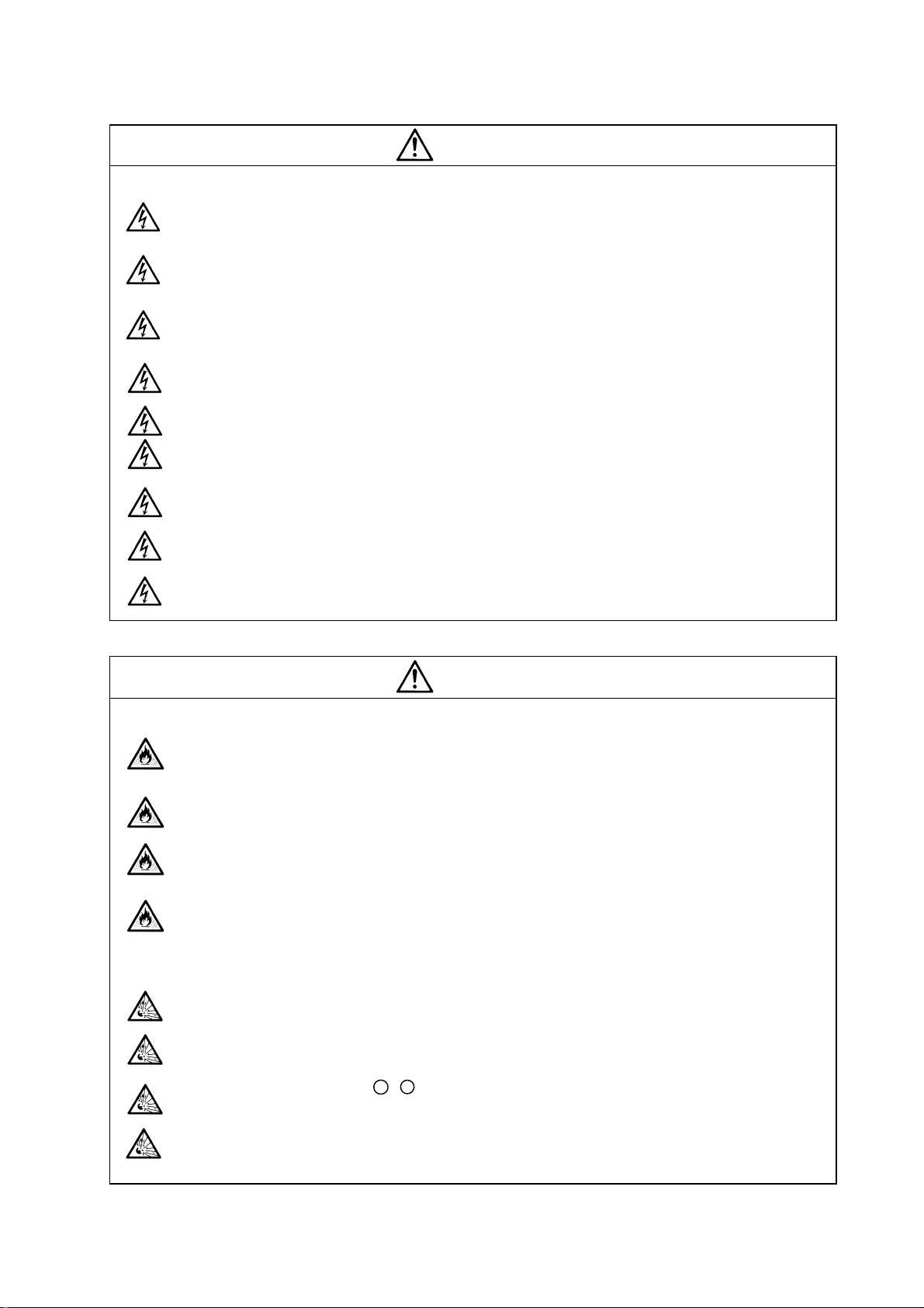
1. Electric shock prevention
Do not open the front cover while the power is ON or during operation. Failure to observe this
could lead to electric shocks.
Do not operate the unit with the front cover removed. The high voltage terminals and charged
sections will be exposed, and can cause electric shocks.
Do not remove the front cover even when the power is OFF unless carrying out wiring work or
periodic inspections. The inside of the units is charged, and can cause electric shocks.
Wait at least 15 minutes after turning the power OFF before starting wiring, maintenance or
inspections. Failure to observe this could lead to electric shocks.
Ground the servo drive unit and servomotor with Class C (former class 3) grounding or higher.
Wiring, maintenance and inspection work must be done by a qualified technician.
Wire the servo drive unit and servomotor after installation. Failure to observe this could lead to
electric shocks.
Do not touch the switches with wet hands. Failure to observe this could lead to electric shocks.
Do not damage, apply forcible stress, place heavy items on the cables or get them caught.
Failure to observe this could lead to electric shocks.
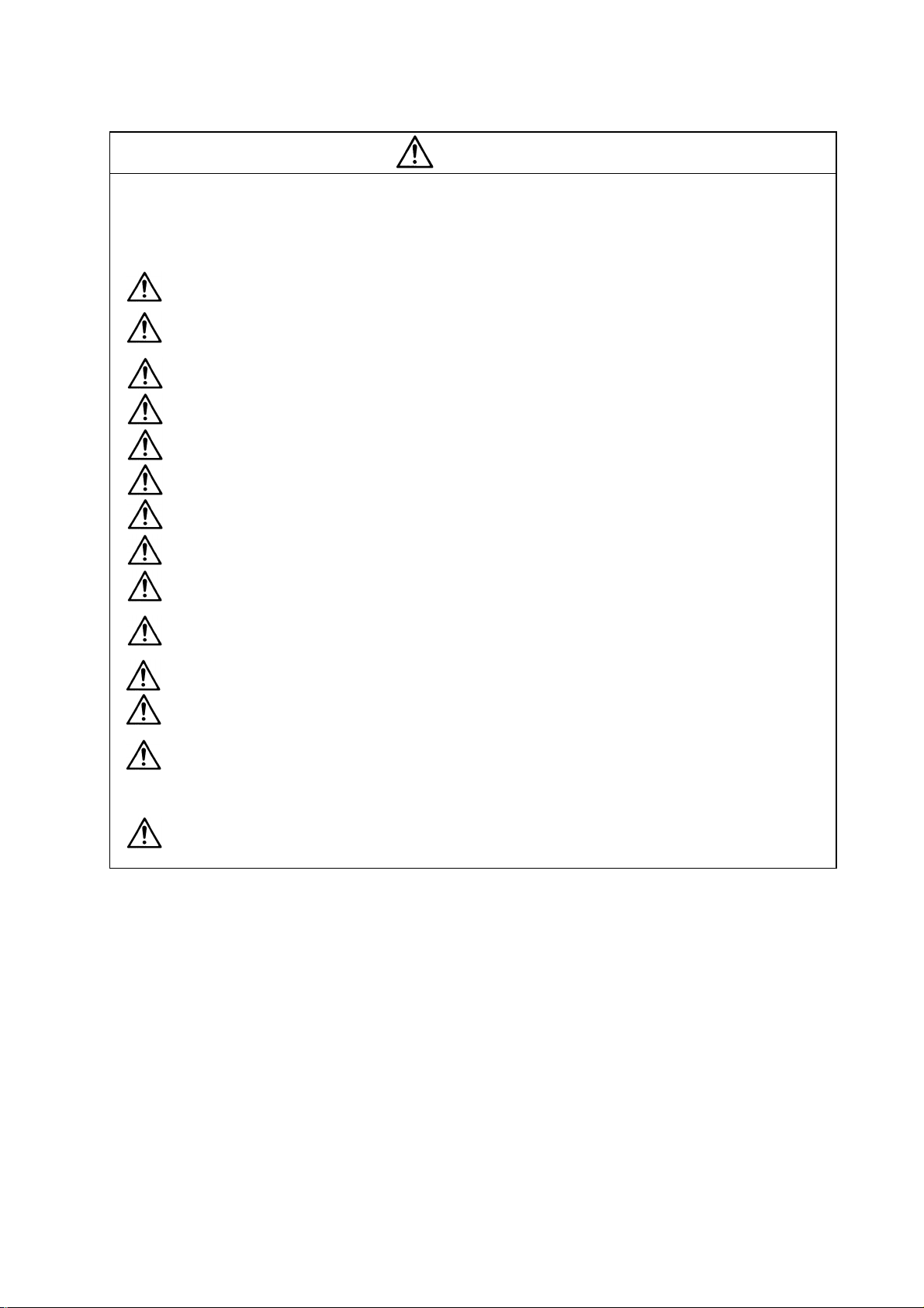
WARNING
1. Fire prevention
Install the servo drive units, servomotors and regenerative resistor on noncombustible
material. Direct installation on combustible material or near combustible materials could le ad
to fires.
Shut off the power on the servo drive unit side if the servo drive unit fails. Fires could be
caused if a large current continues to flow.
When using a regenerative resistor, provide a sequence that shuts off the power with the
regenerative resistor's error signal. The regenerative resistor could abnormally o v erheat and
cause a fire due to a fault in the regenerative transistor, etc.
The battery unit could heat up, ignite or rupture if submerged in water, or if the poles are
incorrectly wired.
2. Injury prevention
Do not apply a voltage other than that specified in Instruction Manual on each terminal. Failure
to observe this item could lead to ruptures or damage, etc.
Do not mistake the terminal connections. Failure to observe this item could lead to ruptures or
damage, etc.
Do not mistake the polarity (
damage, etc.
The servo drive unit's fins, regenerative resistor and servomotor, etc., may reach high
temperatures while the power is ON, and may remain hot for some time after the power is
turned OFF. Touching these parts could result in burns.
CAUTION
+
,
). Failure to observe this item could lead to ruptures or
Page 6
CAUTION
3. Various precautions
Observe the following precautions. Incorrect handling of the unit could lead to faults, injuries and
electric shocks, etc.
(1) Transportation and installation
Correctly transport the product according to its weight.
Use the servomotor's hanging bolts only when transporting the servomotor. Do not transport
the servomotor when it is installed on the machine.
Do not stack the products above the tolerable number.
Do not hold the cables, axis or detector when transporting the servomotor.
Do not hold the connected wires or cables when transporting the servo drive units.
Do not hold the front cover when transporting the servo drive units. The unit could drop.
Follow this Instruction Manual and install in a place where the weight can be borne.
Do not get on top of or place heavy objects on the unit.
Always observe the installation directions.
Secure the specified distance between the servo drive unit and control panel's inne r wall, and
between other devices.
Do not install or run a servo drive unit or servomotor that is damaged or missing parts.
Do not block the intake or exhaust ports of the servomotor provided with a cooling fan.
Do not let foreign objects enter the servo drive units or servomotors. In particular, if
conductive objects such as screws or metal chips, etc., or combustible materials such as oil
enter, rupture or breakage could occur.
The servo drive units and servomotors are precision devices, so do not drop them or apply
strong impacts to them.
Page 7
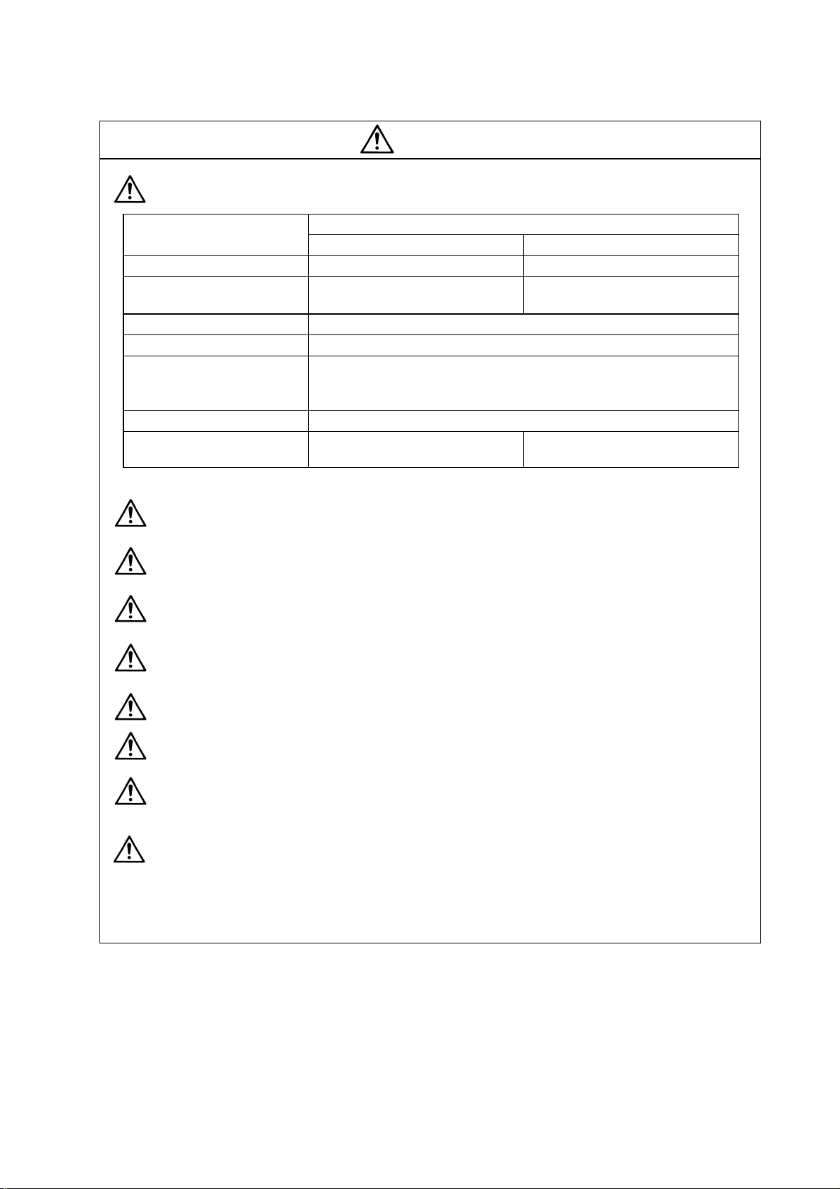
CAUTION
Store and use the units under the following environment conditions.
Ambient temperature 0°C to +55°C (with no freezing) 0°C to +40°C (with no freezing)
Ambient humidity
Storage temperature -15°C to +70°C
Storage humidity 90%RH or less (with no dew condensation)
Atmosphere
Altitude 1,000m or less above sea level
Environment
Vibration 4.9m/s
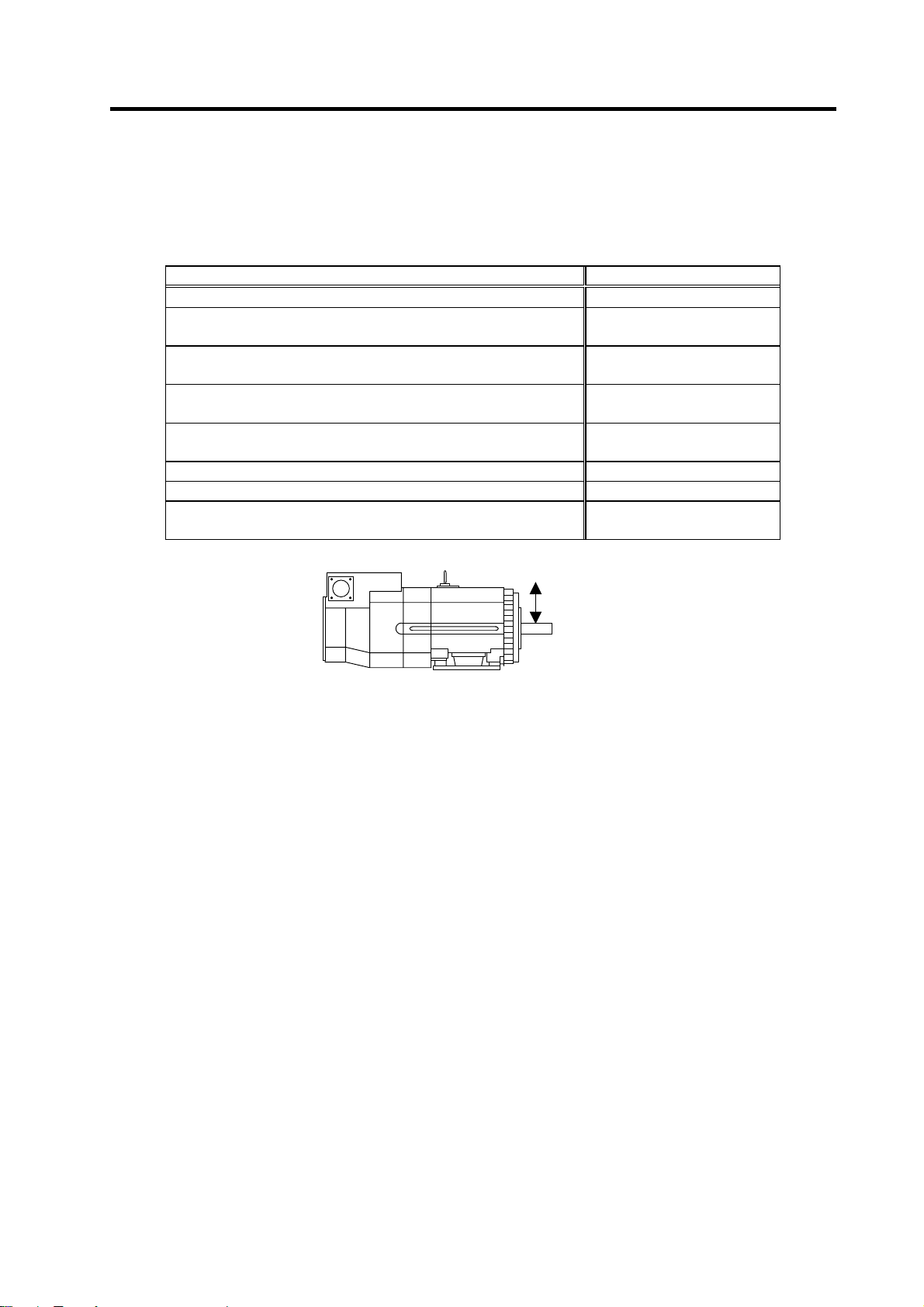
Securely fix the servomotor to the machine. Insufficient fixing could lead to the servomotor
slipping off during operation.
Always install the servomotor with reduction gear in the designated direction. Failure to do
so could lead to oil leaks.
Structure the rotary sections of the motor so that it can never be touched during operation.
Install a cover, etc., on the shaft.
When installing a coupling to a servomotor shaft end, do not apply an impact by
hammering, etc. The detector could be damaged.
Do not apply a load exceeding the tolerable load onto the servomotor shaft. The shaft
could break.
Store the motor in the package box.
When inserting the shaft into the built-in IPM motor, do not heat the rotor higher than
130°C. The magnet could be demagnetized, and the specifications characteristics will not
be ensured.
If the unit has been stored for a long time, always check the operation before starting
actual operation. Please contac t the Service Center or Service Station.
Servo drive unit Servomotor
90%RH or less
(with no dew condensation)
Indoors (where unit is not subject to direct sunlight),
with no corrosive gas, combustible gas, oil mist,
dust or conductive particles
2
(0.5G) or less
Conditions
80% RH or less
(with no dew condensation)
To follow each unit and motor
specifications
Page 8
(2) Wiring
CAUTION
Correctly and securely perform the wiring. Failure to do so could lead to runaway of the
servomotor.
Do not install a condensing capacitor, surge absorber or radio noise filter on the output side of
the servo drive unit.
Correctly connect the output side (terminals U, V, W). Failure to do so could lead to abnormal
operation of the servomotor.
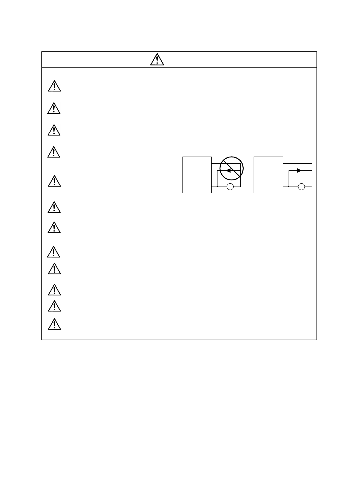
Do not directly connect a commercial
power supply to the servomotor. Failure
to observe this could result in a fault.
Servodrive unit
COM
(24VDC)
Servodrive unit
COM
(24VDC)
When using an inductive load such as a
relay, always connect a diode as a noise
measure parallel to the load.
Controloutput
signal
RA
Control output
signal
When using a capacitance load such as a lamp, always connect a protective resistor a s a
noise measure serial to the load.
Do not reverse the direction of a diode which connect to a DC relay for the control output
signals to suppress a surge. Connecting it backwards could cause the drive unit to malfunction
so that signals are not output, and emergency stop and other safety circuits are inoperable.
Do not connect/disconnect the cables connected between the units while the power is ON.
Securely tighten the cable connector fixing screw or fixing mechanism. An insecure fixing could
cause the cable to fall off while the power is ON.
When using a shielded cable instructed in the connection manual, always ground the cable with
a cable clamp, etc.
Always separate the signals wires from the drive wire and power line.
Use wires and cables that have a wire diameter, heat resistance and flexibility that conforms to
the system.
RA
Page 9
(3) Trial operation and adjustment
Check and adjust each program and parameter before starting operation. Failure to do so could
lead to unforeseen operation of the machine.
Do not make remarkable adjustments and changes as the operatio n could become unstable.
(4) Usage methods
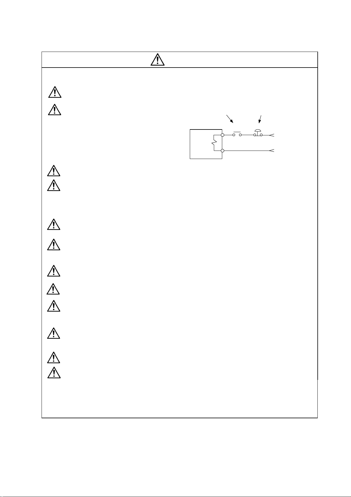
Install an external emergency stop circuit so that the operation can be stopped and power
shut off immediately.
Turn the power OFF immediately if smoke, abnormal noise or odors are generated from the
servo drive unit or servomotor.
Unqualified persons must not disassemble or repair the unit.
Never make modifications.
Reduce magnetic damage by installing a noise filter. The electronic devices used near the
servo drive unit could be affected by magnetic noise.
Use the servo drive unit, servomotor and regenerative resistor with the designated combination.
Failure to do so could lead to fires or trouble.
The brake (magnetic brake) assembled into the servomotor is for holding, and must not be used
for normal braking.
There may be cases when holding is not possible due to the magnetic brake's life or the
machine construction (when ball screw and servomotor are coupled via a timing belt, etc.).
Install a stop device to ensure safety on the machine side.
After changing the programs/parameters or after maintenance and inspection, always test the
operation before starting actual operation.
Do not enter the movable range of the machine during automatic operation. Never place body
parts near or touch the spindle during rotation.
Follow the power supply specification conditions given in the separate specifications manual for
the power (input voltage, input frequency, tolerable sudden power failure time, etc.).
Set all bits to "0" if they are indicated as not used or empty in the explanation on the bits.
Do not use the dynamic brakes except during the emergency stop. Continued use of the
dynamic brakes could result in brake damage.
If a breaker is shared by several power supply units, the breaker may not activate when a
short-circuit fault occurs in a small capacity unit. This is dangerous, so never share the
breakers.
CAUTION
Page 10
(5) Troubleshooting
If a hazardous situation is predicted during power failure or product trouble, use a servomotor
with magnetic brakes or install an external brake mechanism.
Use a double circuit configuration
that allows the operation circuit for
the magnetic brakes to be operated
even by the external emergency
stop signal.
CAUTION
Shut off with the servomotor
brake control output.
Servomotor
Magnetic
brake
Shut off with NC brake
control PLC output.
MBR
EMG
24VDC
Always turn the input power OFF when an alarm occurs.
Never go near the machine after restoring the power after a power failure, as the machine
could start suddenly. (Design the machine so that personal safety can be ensured even if the
machine starts suddenly.)
(6) Maintenance, inspection and part replacement
Always carry out maintenance and inspection after backing up the servo drive unit's programs
or parameters.
The capacity of the electrolytic capacitor will drop over time. To prevent secondary disasters
due to failures, replacing this part every five years when used under a normal environment is
recommended. Contact the Service Center or Service Station for replacement.
Do not perform a megger test (insulation resistance measurement) during inspections.
If the battery low warning is issued, save the machining programs, tool data and parameters
with an input/output unit, and then replace the battery.
Do not short circuit, charge, overheat, incinerate or disassemble the battery.
(7) Disposal
Treat this unit as general industrial waste. Note that MDS Series unit with a heat dissipating
fin protruding from the back of the unit contains substitute Freon. Do not dispose of this type
of unit as general industrial waste. Always return to the Service Center or Service Station.
Do not disassemble the servo drive unit or servomotor parts.
Dispose of the battery according to local laws.
(8) General precautions
The drawings given in this Specifications and Maintenance Instruction Manual show the covers and
safety partitions, etc., removed to provide a clearer explanation. Always return the covers or partitions to
their respective places before starting operation, and always follow the instructions given in this manual.
Page 11

CONTENTS
1. Installation
1-1 Installation of servomotor..................................................................................................... 1-2
1-1-1 Environmental conditions .............................................................................................. 1-2
1-1-2 Quakeproof level............................................................................................................ 1-2
1-1-3 Cautions for mounting load (prevention of impact on shaft)......................................... 1-3
1-1-4 Installation direction .......................................................................................................1-3
1-1-5 Shaft characteristics ...................................................................................................... 1-4
1-1-6 Oil/water standards........................................................................................................ 1-5
1-1-7 Cable stress................................................................................................................... 1-7
1-2 Installation of spindle motor.................................................................................................1-8
1-2-1 Environmental conditions .............................................................................................. 1-8
1-2-2 Shaft characteristics ...................................................................................................... 1-9
1-3 Installation of the control unit.............................................................................................1-10
1-3-1 Environmental conditions ............................................................................................ 1-10
1-3-2 Installation direction and clearance ............................................................................. 1-11
1-3-3 Prevention of entering of foreign matter...................................................................... 1-11
1-3-4 Panel installation hole work drawings (Panel cut drawings).......................................1-12
1-3-5 Heating value............................................................................................................... 1-13
1-3-6 Heat radiation countermeasures................................................................................. 1-14
1-4 Installing the spindle detector............................................................................................ 1-16
1-4-1 Magnetic sensor .......................................................................................................... 1-16
1-4-2 Spindle end detector....................................................................................................1-18
1-4-3 Spindle end PLG.......................................................................................................... 1-19
1-5 Noise measures ................................................................................................................. 1-22
2. Wiring and Connection
2-1 Part system connection diagram......................................................................................... 2-3
2-2 Main circuit terminal block/control circuit connector............................................................ 2-4
2-2-1 Names and applications of main circuit terminal block signals and control circuit
connectors..................................................................................................................... 2-4
2-2-2 Connector pin assignment............................................................................................. 2-5
2-3 NC and drive unit connection ......................................................................................................... 2-8
2-4 Motor and detector connection.....................................................................................................2-11
2-4-1 Connecting the servomotor ......................................................................................... 2-11
2-4-2 Connecting the full-closed loop system....................................................................... 2-18
2-4-3 Connecting the synchronous control system .............................................................. 2-22
2-4-4 Connection of the spindle motor.................................................................................. 2-28
2-5 Connection of power supply.............................................................................................. 2-33
2-5-1 Power supply input connection ...................................................................................... 2-34
2-5-2 Connecting the grounding cable.................................................................................. 2-37
2-5-3 Main circuit control ......................................................................................................... 2-38
2-6 Wiring of the motor brake .................................................................................................. 2-39
2-6-1 Wiring of the motor magnetic brake ............................................................................ 2-39
2-6-2 Dynamic brake unit wiring ........................................................................................... 2-41
2-7 Peripheral control wiring....................................................................................................... 2-42
2-7-1 Input/output circuit wiring ............................................................................................... 2-42
2-7-2 Spindle coil changeover .............................................................................................. 2-43
2-7-3 Wiring of an external emergency stop......................................................................... 2-46
Page 12

3. Setup
3-1 Initial setup ........................................................................................................................... 3-2
3-1-1 Setting the rotary switch ................................................................................................3-2
3-1-2 Transition of LED display after power is turned ON...................................................... 3-3
3-1-3 Servo standard specifications and high-gain specifications ......................................... 3-4
3-2 Setting the initial parameters for the servo drive unit (High-gain specifications)................ 3-5
3-2-1 Setting the standard parameters................................................................................... 3-5
3-2-2 List of standard parameters for each servomotor....................................................... 3-11
3-2-3 Servo parameter list.....................................................................................................3-23
3-3 Setting the initial parameters for the servo drive unit (Standard specifications)............... 3-39
3-3-1 Setting the standard parameters................................................................................. 3-39
3-3-2 List of standard parameters for each servomotor....................................................... 3-44
3-3-3 Servo parameter list.....................................................................................................3-51
3-4 Restrictions on servo control ............................................................................................. 3-63
3-4-1 Restrictions of electronic gear setting value................................................................ 3-63
3-4-2 Restrictions on absolute position control..................................................................... 3-64
3-5 Setting the initial parameters for the spindle drive unit..................................................... 3-65
3-5-1 Spindle specification parameters ................................................................................ 3-65
3-5-2 List of spindle parameters ........................................................................................... 3-70
3-6 Initial adjustment of the spindle PLG............................................................................... 3-104
3-6-1 Adjusting the PLG installation.................................................................................... 3-104
3-6-2 Z phase automatic adjustment.................................................................................. 3-110
3-6-3 Motor end PLG automatic adjustment....................................................................... 3-111
3-6-4 Spindle end PLG automatic adjustment.................................................................... 3-112
4. Servo Adjustment
4-1 D/A output specifications for servo drive unit...................................................................... 4-2
4-1-1 D/A output specifications............................................................................................... 4-2
4-1-2 Output data settings....................................................................................................... 4-3
4-1-3 Setting the output magnification.................................................................................... 4-3
4-2 Gain adjustment................................................................................................................... 4-4
4-2-1 Current loop gain........................................................................................................... 4-4
4-2-2 Speed loop gain............................................................................................................. 4-4
4-2-3 Position loop gain .......................................................................................................... 4-6
4-3 Characteristics improvement............................................................................................... 4-9
4-3-1 Optimal adjustment of cycle time .................................................................................. 4-9
4-3-2 Vibration suppression measures................................................................................. 4-11
4-3-3 Improving the cutting surface precision....................................................................... 4-15
4-3-4 Improvement of characteristics during acceleration/deceleration .............................. 4-19
4-3-5 Improvement of protrusion at quadrant changeover................................................... 4-22
4-3-6 Improvement of overshooting...................................................................................... 4-29
4-3-7 Improvement of the interpolation control path............................................................. 4-31
4-4 Adjustment during full closed loop control......................................................................... 4-33
4-4-1 Outline.......................................................................................................................... 4-33
4-4-2 Speed loop delay compensation................................................................................. 4-34
4-4-3 Dual feedback control (Optional function)................................................................... 4-35
4-5 Settings for emergency stop.............................................................................................. 4-37
4-5-1 Deceleration control..................................................................................................... 4-37
4-5-2 Vertical axis drop prevention control........................................................................... 4-39
4-6 Protective functions............................................................................................................ 4-43
4-6-1 Overload detection....................................................................................................... 4-43
4-6-2 Excessive error detection............................................................................................ 4-43
4-6-3 Collision detection........................................................................................................ 4-44
Page 13

5. Spindle Adjustment
5-1 D/A output specifications for spindle drive unit ................................................................... 5-2
5-1-1 D/A output specifications............................................................................................... 5-2
5-1-2 Setting the output data ..................................................................................................5-3
5-1-3 Setting the output magnification.................................................................................... 5-4
5-2 Spindle control signal........................................................................................................... 5-6
5-2-1 Spindle control input (NC to SP) ................................................................................... 5-6
5-2-2 Spindle control output (SP to NC)............................................................................... 5-15
5-3 Adjustment procedures for each control ........................................................................... 5-26
5-3-1 Basic adjustments........................................................................................................ 5-26
5-3-2 Adjusting the acceleration/deceleration operation...................................................... 5-27
5-3-3 Adjusting the orientation control.................................................................................. 5-36
5-3-4 Adjusting the synchronous tap control ........................................................................ 5-50
5-3-5 Adjusting the C-axis control......................................................................................... 5-54
5-3-6 Adjusting the spindle synchronous control.................................................................. 5-57
6. Troubleshooting
6-1 Points of caution and confirmation ...................................................................................... 6-2
6-1-1 LED display when alarm or warning occurs.................................................................. 6-3
6-2 Protective functions list of units ...........................................................................................6-4
6-2-1 List of alarms.................................................................................................................. 6-4
6-2-2 List of warnings .............................................................................................................. 6-9
6-3 Troubleshooting ................................................................................................................. 6-10
6-3-1 Troubleshooting at power ON ..................................................................................... 6-10
6-3-2 Troubleshooting for each alarm No............................................................................. 6-11
6-3-3 Troubleshooting for each warning No......................................................................... 6-40
6-3-4 Parameter numbers during initial parameter error...................................................... 6-44
6-3-5 Troubleshooting the spindle system when there is no alarm or warning ................... 6-45
7. Maintenance
7-1 Inspections........................................................................................................................... 7-2
7-2 Service parts ........................................................................................................................ 7-2
7-3 Adding and replacing units and parts.................................................................................. 7-3
7-3-1 Replacing the drive unit.................................................................................................7-3
7-3-2 Replacing the unit fan.................................................................................................... 7-4
Appendix 1. Cable and Connector Specifications
Appendix 1-1 Selection of cable ..............................................................................................A1-2
Appendix 1-1-1 Cable wire and assembly............................................................................A1-2
Appendix 1-1-2 Flexible conduits..........................................................................................A1-4
Appendix 1-2 Cable connection diagram.................................................................................A1-6
Appendix 1-3 Connector outline dimension drawings...........................................................A1-13
Appendix 2. Compliance to EC Directives
Appendix 2-1 Compliance to EC Directives ............................................................................A2-2
Appendix 2-1-1 European EC Directives..............................................................................A2-2
Appendix 2-1-2 Cautions for EC Directive compliance...........................................................A2-2
Page 14

Appendix 3.
EMC Installation Guidelines
Appendix 3-1 Introduction ........................................................................................................A3-2
Appendix 3-2 EMC instructions ...............................................................................................A3-2
Appendix 3-3 EMC measures..................................................................................................A3-3
Appendix 3-4 Measures for panel structure.............................................................................A3-3
Appendix 3-4-1 Measures for control panel unit...................................................................A3-3
Appendix 3-4-2 Measures for door .......................................................................................A3-4
Appendix 3-4-3 Measures for operation board panel...........................................................A3-4
Appendix 3-4-4 Shielding of the power supply input section................................................A3-4
Appendix 3-5 Measures for various cables .............................................................................A3-5
Appendix 3-5-1 Measures for wiring in panel .......................................................................A3-5
Appendix 3-5-2 Measures for shield treatment.....................................................................A3-5
Appendix 3-5-3 Servo/spindle motor power cable................................................................A3-6
Appendix 3-5-4 Servo motor feedback cable .......................................................................A3-7
Appendix 3-5-5 Spindle motor feedback cable.....................................................................A3-7
Appendix 3-6 EMC countermeasure parts ..............................................................................A3-8
Appendix 3-6-1 Shield clamp fitting ......................................................................................A3-8
Appendix 3-6-2 Ferrite core ..................................................................................................A3-9
Appendix 3-6-3 Power line filter..........................................................................................A3-10
Appendix 3-6-4 Surge protector..........................................................................................A3-15
Appendix 4. Servo/spindle drive unit categories based on higher harmonic suppression
countermeasure guidelines
Appendix 4-1 Servo/spindle drive unit circuit categories based on higher harmonic suppression
countermeasure guidelines...............................................................................A4-2
Page 15

Contents for MDS-C1 Series SPECIFICATIONS MANUAL (BNP-C3040D)
1. Introduction
1-1 Servo/spindle drive system configuration............1-2
1-1-1 System configuration.................................................1-2
1-1-2 Unit outline type.........................................................1-3
1-2 Explanation of type..............................................1-4
1-2-1 Servomotor type........................................................1-4
1-2-2 Servo drive unit type..................................................1-8
1-2-3 Spindle motor type.....................................................1-10
1-2-4 Spindle drive unit type ...............................................1-12
1-2-5 Power supply unit type...............................................1-13
1-2-6 AC reactor type..........................................................1-14
2. Specifications
2-1 Servomotor..........................................................2-2
2-1-1 Specifications list....................................................... 2-2
2-1-2 Torque characteristics ...............................................2-7
2-2 Spindle motor ......................................................2-10
2-2-1 Specifications............................................................2-10
2-2-2 Output characteristics................................................2-15
2-3 Drive unit .............................................................2-20
2-3-1 Servo drive unit..........................................................2-20
2-3-2 Spindle drive unit.......................................................2-22
2-3-3 Power supply unit ......................................................2-23
2-3-4 AC reactor .................................................................2-24
2-3-5 D/A output specifications for servo drive unit.............2-25
2-3-6 D/A output specifications for spindle drive unit...........2-26
2-3-7 Explanation of each part............................................2-27
2-4 Restrictions on servo control...............................2-30
2-4-1 Restrictions of electronic gear setting value...............2-30
2-4-2 Restrictions on absolute position control....................2-32
3. Characteristics
3-1 Servomotor..........................................................3-2
3-1-1 Environmental conditions...........................................3-2
3-1-2 Quakeproof level.......................................................3-2
3-1-3 Shaft characteristics ..................................................3-3
3-1-4 Oil/water standards....................................................3-4
3-1-5 Magnetic brake..........................................................3-5
3-1-6 Dynamic brake characteristics...................................3-8
3-2 Spindle motor ......................................................3-10
3-2-1 Environmental conditions...........................................3-10
3-2-2 Shaft characteristics ..................................................3-10
3-3 Drive unit characteristics .....................................3-11
3-3-1 Environmental conditions...........................................3-11
3-3-2 Heating value.............................................................3-12
3-3-3 Overload protection characteristics............................3-13
4. Dedicated Options
4-1 Servo options ......................................................4-2
4-1-1 Battery and terminator option (mandatory selection)..4-3
4-1-2 Dynamic brake unit (MDS-B-DBU)
(mandatory selection for large capacity)....................4-5
4-1-3 Ball screw end detector .............................................4-7
4-1-4 Machine end detector ................................................ 4-8
4-1-5 Detector conversion unit (MDS-B-HR).......................4-10
4-1-6 Signal divider unit (MDS-B-SD) .................................4-12
(Note) This is the content for SPECIFICATION MANUAL version D. The structure of section and page number may be different
other than version D.
4-2 Spindle option .....................................................4-14
4-2-1 Magnetic sensor........................................................4-16
4-2-2 Spindle end detector
(OSE-1024-3-15-68, OSE-1024-3-15-68-8)..............4-18
4-2-3 C-axis detector (OSE90K).........................................4-20
4-2-4 C-axis detector (MBE90K).........................................4-22
4-2-5 C-axis detector (MHE90K).........................................4-23
4-2-6 Spindle end PLG (MXE128/180/256/512)..................4-24
4-2-7 Detector conversion unit (MDS-B-PJEX)...................4-28
4-3 Cables and connectors ....................................... 4-30
4-3-1 Cable connection diagram.........................................4-30
4-3-2 List of cables and connectors....................................4-31
5. Peripheral Devices
5-1 Selecting the wire size........................................5-2
5-2 Selection the AC reactor, contactor
and no-fuse breaker...........................................5-5
5-2-1 Standard selection.....................................................5-5
5-2-2 Selection when a contactor is shared........................5-6
5-3 Circuit protector .................................................. 5-7
5-4 Circuit protector .................................................. 5-8
5-5 Noise filter........................................................... 5-9
5-6 Surge absorber ................................................... 5-10
5-7 Speedometer and load meter............................. 5-11
5-8 Cable for peripheral control ................................5-12
5-8-1 Cable for external emergency stop............................5-12
5-8-2 Cable for servomotor magnetic brake........................5-13
Appendix 1. Outline Dimension Drawings
Appendix 1-1 Servomotor outline dimension drawings
............................................................A1-2
Appendix 1-1-1 HC Series..................................................A1-2
Appendix 1-1-2 HA Series ..................................................A1-8
Appendix 1-2 Outline dimension drawings
of spindle motor................................... A1-12
Appendix 1-2-1 SJ Series...................................................A1-12
Appendix 1-2-2 SJ-V Series................................................ A1-15
Appendix 1-2-3 SJ-VS Series .............................................A1-25
Appendix 1-2-4 SJ-PMF Series (IPM motor).......................A1-27
Appendix 1-3 Unit outline dimension drawings.........A1-28
Appendix 1-3-1 Servo/spindle drive unit .............................A1-28
Appendix 1-3-2 Power supply unit ......................................A1-37
Appendix 1-3-3 AC rector ...................................................A1-41
Appendix 2. Table and Connector Specifications
Appendix 2-1 Selection of cable ...............................A2-2
Appendix 2-1-1 Cable wire and assembly...........................A2-2
Appendix 2-1-2 Flexible conduits........................................A2-4
Appendix 2-2 Cable connection diagram..................A2-6
Appendix 2-3 Connector outline dimension drawings
............................................................A2-12
Appendix 3. Selection
Appendix 3-1 Selecting the servomotor series .........A3-2
Appendix 3-1-1 Motor series characteristics.......................A3-2
Appendix 3-1-2 Servomotor precision.................................A3-3
Appendix 3-2 Selection of servomotor capacity........ A3-4
Appendix 3-2-1 Load inertia ratio........................................A3-4
Appendix 3-2-2 Short time characteristics...........................A3-4
Appendix 3-2-3 Continuous characteristics.........................A3-5
Page 16

Contents for MDS-C1 Series SPECIFICATIONS MANUAL (BNP-C3040D)
Appendix 3-3 Example of servo selection.................A3-7
Appendix 3-3-1 Motor selection calculation.........................A3-7
Appendix 3-3-2 Servo selection results...............................A3-10
Appendix 3-3-3 Motor shaft conversion load torque............A3-11
Appendix 3-3-4 Expressions for load inertia calculation......A3-12
Appendix 3-4 Selecting the power supply.................A3-13
Appendix 3-4-1 Selecting according to the continuous rated
capacity.....................................................A3-13
Appendix 3-4-2 Selection with maximum momentary capacity
..................................................................A3-14
Appendix 3-4-3 Selection example......................................A3-15
Appendix 4. Explanation of Large Capacity Spindle Unit
Specifications
Appendix 4-1 Explanation of large capacity spindle unit
specifications.......................................A4-2
Appendix 4-1-1 Outline.......................................................A4-2
Appendix 4-1-2 List of units.................................................A4-2
Appendix 4-1-3 Selection of AC reactor (B-AL),
contactor and NFB....................................A4-2
Appendix 4-1-4 Outline dimension drawings .......................A4-3
Appendix 4-1-5 Panel cut dimension drawing.....................A4-8
Appendix 4-1-6 Heating value.............................................A4-9
Appendix 4-1-7 Selecting the power capacity.....................A4-9
Appendix 4-1-8 Selecting the wire size...............................A4-9
Appendix 4-1-9 Drive unit connection screw size................A4-10
Appendix 4-1-10 Connecting each unit...............................A4-10
Appendix 4-1-11 Restrictions..............................................A4-12
Appendix 4-1-12 Parameters..............................................A4-14
Appendix 4-1-13 Precautions..............................................A4-14
Appendix 5. Transportation Restrictions for Lithium Batteries
Appendix 5-1 Transportation restrictions
for lithium batteries ..............................A5-2
Appendix 5-1-1 Target products..........................................A5-2
Appendix 5-1-2 Handling by user........................................A5-3
Appendix 5-1-3 Regulations enforcement timing.................A5-4
Appendix 6. Compliance to EU EC Directives
Appendix 6-1 Compliance to EC Directives ..............A6-2
Appendix 6-1-1 European EC Directives.............................A6-2
Appendix 6-2-2 Cautions for EC Directive compliance ..........A6-2
Appendix 7. EMS Instruction Guidelines
Appendix 7-1 Introduction ......................................... A7-2
Appendix 7-2 EMC instructions................................. A7-2
Appendix 7-3 EMC measures ...................................A7-3
Appendix 7-4 Measures for panel structure..............A7-3
Appendix 7-4-1 Measures for control panel unit..................A7-3
Appendix 7-4-2 Measures for door......................................A7-4
Appendix 7-4-3 Measures for operation board panel..........A7-4
Appendix 7-4-4 Shielding of the power supply input section
..................................................................A7-4
Appendix 7-5 Measures for various cables...............A7-5
Appendix 7-5-1 Measures for wiring in panel......................A7-5
Appendix 7-5-2 Measures for shield treatment ...................A7-5
Appendix 7-5-3 Servomotor power cable............................A7-6
Appendix 7-5-4 Servomotor feedback cable.......................A7-6
Appendix 7-5-5 Spindle motor power cable........................A7-7
Appendix 7-5-6 Spindle motor feedback cable....................A7-7
Appendix 7-6 EMC countermeasure parts................ A7-8
Appendix 7-6-1 Shield clamp fitting.....................................A7-8
Appendix 7-6-2 Ferrite core................................................A7-9
Appendix 7-6-3 Power line filter..........................................A7-10
Appendix 7-6-4 Surge protector ..........................................A7-15
Appendix 8. Instruction Manual for Compliance with UL/c-UL
Standard
Appendix 8. Instruction Manual for Compliance
with UL/c-UL Standard........................ A8-2
Appendix 9. Compliance with China Compulsory Product
Certification (CCC Certification) System
Appendix 9-1 Outline of China Compulsory Product
Certification System ............................A9-2
Appendix 9-2 First Catalogue of Products subject to
Compulsory Product Certification........ A9-2
Appendix 9-3 Precautions for Shipping Products .....A9-3
Appendix 9-4 Application for Exemption...................A9-4
Appendix 9-5 Mitsubishi NC Product Subject to
/Not Subject to CCC Certification........A9-5
(Note) This is the content for SPECIFICATION MANUAL version D. The structure of section and page number may be different
other than version D.
Page 17

1. Installation
1-1 Installation of servomotor...................................................................................................................1-2
1-1-1 Environmental conditions............................................................................................................1-2
1-1-2 Quakeproof level .........................................................................................................................1-2
1-1-3 Cautions for mounting load (prevention of impact on shaft) ....................................................... 1-3
1-1-4 Installation direction..................................................................................................................... 1-3
1-1-5 Shaft characteristics.................................................................................................................... 1-4
1-1-6 Oil/water standards ..................................................................................................................... 1-5
1-1-7 Cable stress ................................................................................................................................1-7
1-2 Installation of spindle motor ............................................................................................................... 1-8
1-2-1 Environmental conditions............................................................................................................1-8
1-2-2 Shaft characteristics.................................................................................................................... 1-9
1-3 Installation of the control unit ........................................................................................................... 1-10
1-3-1 Environmental conditions..........................................................................................................1-10
1-3-2 Installation direction and clearance...........................................................................................1-11
1-3-3 Prevention of entering of foreign matter....................................................................................1-11
1-3-4 Panel installation hole work drawings (Panel cut drawings).....................................................1-12
1-3-5 Heating value.............................................................................................................................1-13
1-3-6 Heat radiation countermeasures............................................................................................... 1-14
1-4 Installing the spindle detector...........................................................................................................1-16
1-4-1 Magnetic sensor........................................................................................................................ 1-16
1-4-2 Spindle end detector ................................................................................................................. 1-18
1-4-3 Spindle end PLG .......................................................................................................................1-19
1-5 Noise measures ...............................................................................................................................1-22
1 - 1
Page 18

X
1-1 Installation of servomotor
1. Do not hold the cables, axis or detector when transporting the motor. Failure to
observe this could lead to faults or injuries.
2. Securely fix the motor to the machine. Insufficient fixing could lead to the
motor deviating during operation. Failure to observe this could lead to
injuries.
CAUTION
1-1-1 Environmental conditions
Environment Conditions
Ambient temperature 0°C to +40°C (with no freezing)
Ambient humidity 80%RH or less (with no dew condensation)
Storage temperature -15°C to +70°C (with no freezing)
Storage humidity 90%RH or less (with no dew condensation)
Atmosphere
Altitude
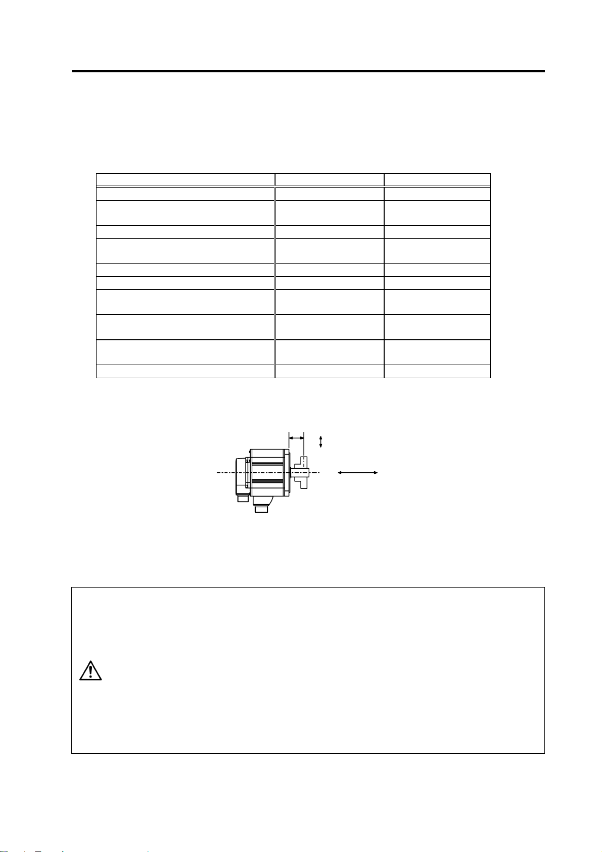
1-1-2 Quakeproof level
HC52 to HC152, HC53 to HC153
HC103R to HC503R, HA053N to HA33N
HC202, HC352, HC203, HC353 19.6m/s2 (2G) or less 49.0m/s2 (5G) or less
HC452, HC702, HC453, HC703
HA-LF11K2-S8, HA-LF15K2-S8
HC902 9.8m/s2 (1G) or less 24.5m/s2 (2.5G) or less
The vibration conditions are as shown below.
200
100
80
60
50
40
30
3. When coupling to a servomotor shaft end, do not apply an impact by
hammering, etc. The detector could be damaged.
4. Never touch the rotary sections of the motor during operations. Install a
cover, etc., on the shaft.
5. Do not apply a load exceeding the tolerable load onto the servomotor shaft.
The shaft could break. Failure to observe this could lead to injuries.
6. Do not connect or disconnect any of the connectors while the power is ON.
Motor type
1. Installation
Indoors (Where unit is not subject to direct sunlight)
No corrosive gases, flammable gases, oil mist or dust
Operation/storage: 1000m or less above sea level
Transportation: 10000m or less above sea level
Acceleration direction
Axis direction (X) Direction at right angle to axis (Y)
2
(1G) or less 24.5m/s2 (2.5G) or less
9.8m/s
2
11.7m/s
(1.2G) or less 29.4m/s2 (3G) or less
X
Servomotor
Y
Y
20
Vibration amplitude
(double-sway width) (µm)
1000 2000 30000
Speed (r/min)
1 - 2
Acceleration
Page 19
r
r
directio
1. Installation
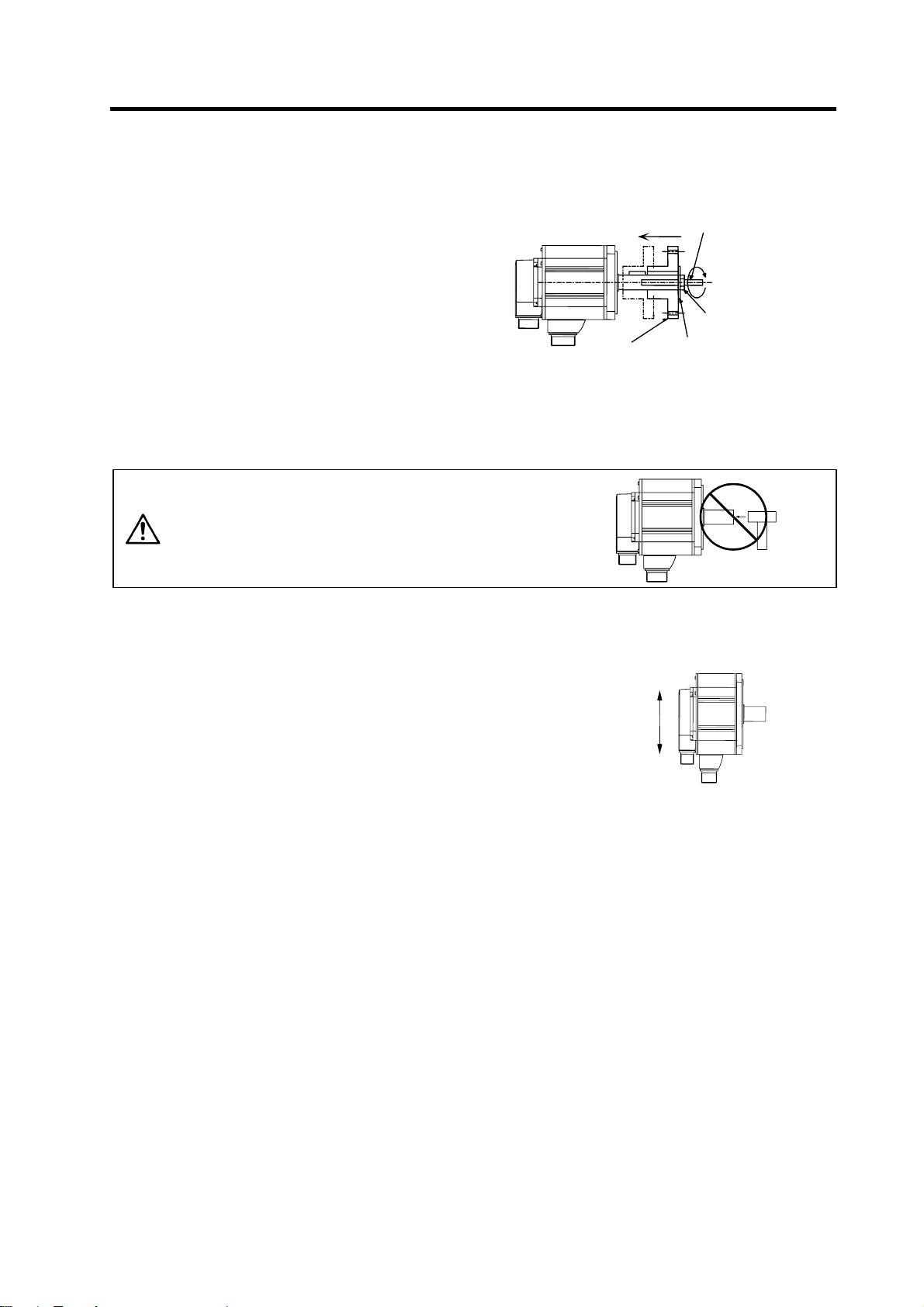
1-1-3 Cautions for mounting load (prevention of impact on shaft)
[1] When using the servomotor with key way, use
the screw hole at the end of the shaft to mount
the pulley onto the shaft. To install, first place
the double-end stud into the shaft screw
holes, contact the coupling end surface
against the washer, and press in as if
tightening with a nut. When the shaft does not
have a key way, use a frictional coupling, etc.
[2] When removing the pulley, use a pulley
remover, and make sure not to apply an
impact on the shaft.
[3] Install a protective cover on the rotary sections such as the pulley installed on the shaft to ensure
safety.
[4] The direction of the detector installed on the servomotor cannot be changed.
Servomoto
Pulley
Double-end stud
Nut
Washe
CAUTION
during assembly.
1-1-4 Installation direction
[1] There are no restrictions on the installation direction. Installation
in any direction is possible, but as a standard the motor is
installed so that the motor power line and detector cable cannon
plugs (lead-in wires) face downward. Installation in the standard
direction is effective against dripping. Measure to prevent oil and
water must be taken when not installing in the standard direction.
When the motor is not installed in the standard direction, refer to
section "1-1-6 Oil/water standards" and take the appropriate
measures.
The brake plates may make a sliding sound when a servomotor
with magnetic brake is installed with the shaft facing upward, but
this is not a fault.
Never hammer the end of the shaft
Up
Down
Standard installation
n
1 - 3
Page 20
1. Installation
1-1-5 Shaft characteristics
There is a limit to the load that can be applied on the motor shaft. Make sure that the load applied on the
radial direction and thrust direction, when mounted on the machine, is below the tolerable values given
below. These loads may affect the motor output torque, so consider them when designing the machine.
Servomotor Tolerable radial load Tolerable thrust load
HA053NS, HA13NS 78.4N (L=26mm) 49N
HA23NS, HA33NS
HA23NT, HA33NT
HC103RT, HC153RT, HC203RT 392N (L=45 mm) 196N
HC52T, HC102T, HC152T
HC53T, HC103T, HC153T
HC103RS, HC153RS, HC203RS 686N (L=45 mm) 196N
HC353RS, HC503RS 980N (L=63 mm) 392N
HC52S, HC102S, HC152S
HC53S, HC103S, HC153S
HC202S, HC352S, HC452S, HC702S
HC203S, HC353S, HC453S, HC703S
HC902S
HA-LF11K2-S8
HA-LF15K2-S8 2940N (L=100 mm) 980N
Note: The symbol L in the table refers to the value of L below.
245N (L=30 mm) 147N
392N (L=58 mm) 490N
980N (L=55 mm) 490N
2058N (L=79 mm) 980N
2450N (L=85 mm) 980N
CAUTION
L
Radial load
Thrust load
L : Length from flange installation surface to center of load weight [mm]
1. Use a flexible coupling when connecting with a ball screw, etc., and keep the
shaft core deviation to below the tolerable radial load of the shaft.
2. When directly installing the gear on the motor shaft, the radial load increases
as the diameter of the gear decreases. This should be carefully considered
when designing the machine.
3. When directly installing the pulley on the motor shaft, carefully consider so
that the radial load (double the tension) generated from the timing belt tension
is less than the values shown in the table above.
4. In machines where thrust loads such as a worm gear are applied, carefully
consider providing separate bearings, etc., on the machine side so that loads
exceeding the tolerable thrust loads are not applied to the motor.
5. Do not use a rigid coupling as an excessive bending load will be applied on
the shaft and could cause the shaft to break.
1 - 4
Page 21
r
1. Installation
1-1-6 Oil/water standards
[1] The motor protective format uses the IP type, which complies with IEC
Standard. However, these Standards are short-term performance
specifications. They do not guarantee continuous environmental
protection characteristics. Measures such as covers, etc., must be
taken if there is any possibility that oil or water will fall on the motor,
and the motor will be constantly wet and permeated by water. Note
that the motor’s IP-type is not indicated as corrosion-resistant.
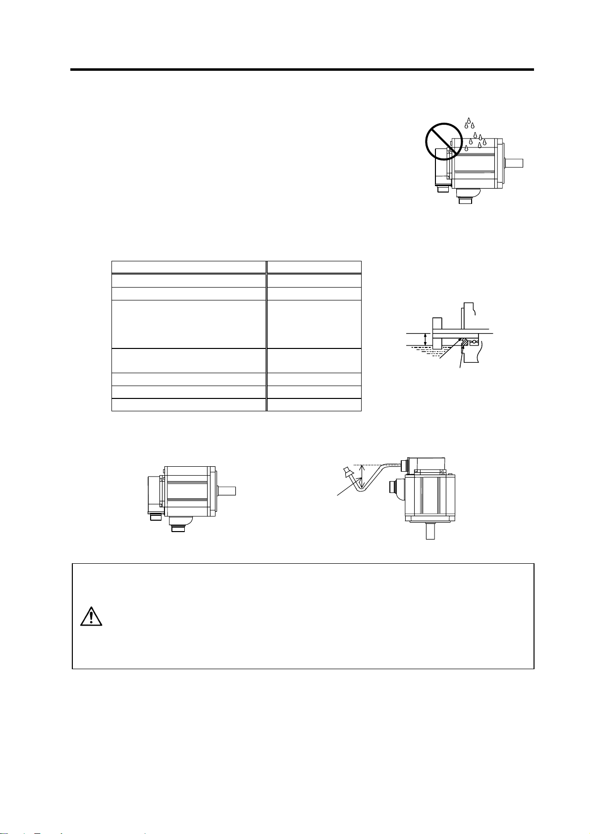
[2] When a gear box is installed on the servomotor, make sure that the oil
level height from the center of the shaft is higher than the values given below. Open a breathing
hole on the gear box so that the inner pressure does not rise.
Servomotor Oil level (mm)
HA053N, HA13N 8
HA23N, HA33N 10
HC52, HC102, HC152
HC53, HC103, HC153
HC103R, HC153R, HC203R
HC353R, HC503R
HC202, HC352, HC452, HC702
HC203, HC353, HC453, HC703
HC902 30
HA-LF11K2-S8 34
HA-LF15K2-S8 48
20
25
Oil level
[3] When installing the servomotor horizontally, set the power cable and detector cable to face
downward. When installing vertically or on an inclination, provide a cable trap.
Gear
Lip
Oil or water
Servomotor
Servomoto
V-ring
Cable trap
1. The servomotors, including those having IP65 specifications, do not have a
completely waterproof (oil-proof) structure. Do not allow oil or water to
constantly contact the motor, enter the motor, or accumulate on the motor. Oil
can also enter the motor through cutting chip accumulation, so be careful of
CAUTION
this also.
2. When the motor is installed facing upwards, take measures on the machine
side so that gear oil, etc., does not flow onto the motor shaft.
3. Do not remove the detector from the motor. (The detector installation screw is
treated for sealing.)
1 - 5
Page 22
1. Installation
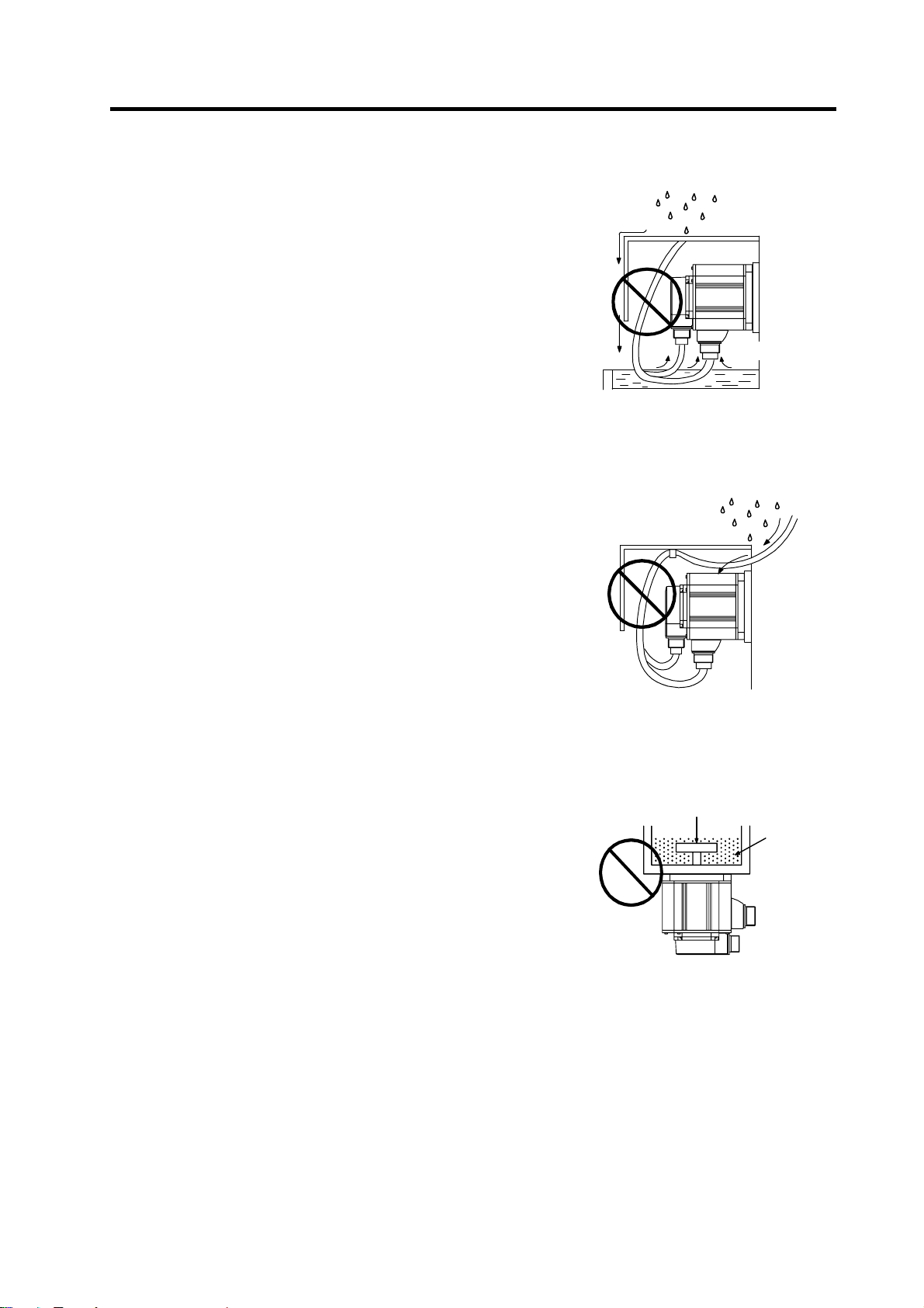
[4] Do not use the unit with the cable submerged in oil or
water.
(Refer to right drawing.)
[5] Make sure that oil and water do not flow along the cable
into the motor or detector. (Refer to right drawing.)
[6] When installing on the top of the shaft end, make sure
that oil from the gear box, etc., does not enter the
servomotor. The servomotor does not have a waterproof
structure.
Cover
Servomotor
Oil water
<Fault> Capillary tube phenomenon
Cover
Servomotor
<Fault> Respiration
Gear
Lubricating oil
Servomotor
1 - 6
Page 23
1. Installation
1-1-7 Cable stress
[1] Sufficiently consider the cable clamping method so that bending stress and the stress from the
cable's own weight is not applied on the cable connection part.
[2] In applications where the servomotor moves, make sure that excessive stress is not applied on the
cable.
If the detector cable and servomotor wiring are stored in a cable bear and the servomotor moves,
make sure that the cable bending part is within the range of the optional detector cable.
Fix the detector cable and power cable enclosed with the servomotor.
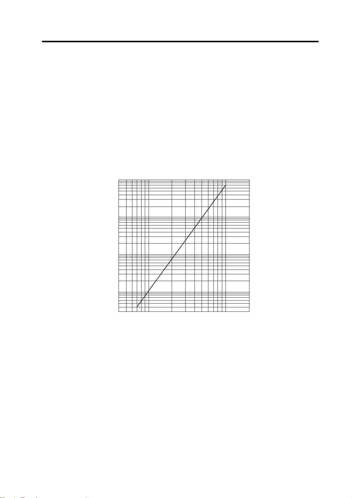
[3] Make sure that the cable sheathes will not be cut by sharp cutting chips, worn by contacting the
machine corners, or stepped on by workers or vehicles.
The bending life of the detector cable is as shown below. Regard this with a slight allowance. If the
servomotor/spindle motor is installed on a machine that moves, make the bending radius as large as
possible.
8
1 x 10⁸
1×10
7
5 x 10⁷
5×10
No. of bends (times)
2 x 10⁷
7
2×10
7
1 x 10⁷
1×10
6
5 x 10⁶
5×10
6
2 x 10⁶
2×10
6
1 x 10⁶
1×10
5
5 x 10⁵
5×10
5
2 x 10⁵
2×10
5
1 x 10⁵
1×10
4
5 x 10⁴
5×10
4
3 x 10⁴
3×10
4 7 10 20 40 70 100 200
4 7 10 20 40 70 100 200
Bending radius (mm)
(Material of Mitsubishi optional detector cable: A14B2343)
The values in this graph are calculated values and are not guaranteed.
(Note)
Detector cable bending life
1 - 7
Page 24

1-2 Installation of spindle motor
1. Do not hold the cables, axis or detector when transporting the motor. Failure to
observe this could lead to faults or injuries.
2. Securely fix the motor to the machine. Insufficient fixing could lead to the
motor deviating during operation. Failure to observe this could lead to
injuries.
CAUTION
1-2-1 Environmental conditions
Environment Conditions
Ambient temperature 0°C to +40°C (with no freezing)
Ambient humidity 90%RH or less (with no dew condensation)
Storage temperature -20°C to +65°C (with no freezing)
Storage humidity 90%RH or less (with no dew condensation)
Atmosphere
Altitude
(Note) Refer to each spindle motor specifications for details on the spindle motor vibration
conditions.
3. When coupling to a servomotor shaft end, do not apply an impact by
hammering, etc. The detector could be damaged.
4. Never touch the rotary sections of the motor during operations. Install a
cover, etc., on the shaft.
5. Do not apply a load exceeding the tolerable load onto the servomotor shaft.
The shaft could break. Failure to observe this could lead to injuries.
6. Do not connect or disconnect any of the connectors while the power is ON.
1. Installation
Indoors (Where unit is not subject to direct sunlight)
No corrosive gases, flammable gases, oil mist or dust
Operation/storage: 1000m or less above sea level
Transportation: 10000m or less above sea level
1 - 8
Page 25
1. Installation
1-2-2 Shaft characteristics
There is a limit to the load that can be applied on the motor shaft. Make sure that the load applied on the
radial direction, when mounted on the machine, is below the tolerable values given below. These loads
also affect the motor output torque, so consider them when designing the machine.
Spindle motor Tolerable radial load
SJ-V3.7-02ZM 490 N
SJ-V2.2-01, SJ-V3.7-01
SJ-V7.5-03ZM, SJ-V11-06ZM
SJ-V5.5-01, SJ-V11-08ZM
SJ-PMF01830-00
SJ-V7.5-01, SJ-V11-01
SJ-V22-06ZM, SJ-V30-02ZM, SJ-PMF03530-00
SJ-V11-09, SJ-V15-01, SJ-V15-03, SJ-V18.5-01, SJ-V18.5-03
SJ-V22-01, SJ-V22-05, SJ-V26-01, SJ-30A
SJ-22XW5 3920 N
SJ-37BP 4900 N
SJ-22XW8, SJ-45BP
SJ-V55-01
Radial load
(Note) The load point is at the one-half of the shaft length.
980 N
1470 N
1960 N
2940 N
5880 N
1 - 9
Page 26
1-3 Installation of the control unit
1. Install the unit on noncombustible material. Direct installation on
combustible material or near combustible materials may lead to fires.
2. Follow the instructions in this manual and install the unit while allowing for
the unit weight.
3. Do not get on top of the units or motor, or place heavy objects on the unit.
Failure to observe this could lead to injuries.
4. Always use the unit within the designated environment conditions.
5. Do not let conductive objects such as screws or metal chips, etc., or
combustible materials such as oil enter the units.
CAUTION
6. Do not block the units intake and outtake ports. Doing so could lead to
failure.
7. The units and servomotor are precision devices, so do not drop them or apply
strong impacts to them.
8. Do not install or run units or servomotor that is damaged or missing parts.
9. When storing for a long time, please contact your dealer.
10. Always observe the installation directions. Failure to observe this could lead to
faults.
11. Secure the specified distance between the units and panel, or between the
units and other devices. Failure to observe this could lead to faults.
1. Installation
1-3-1 Environmental conditions
Environment Conditions
Ambient temperature 0°C to +55°C (with no freezing)
Ambient humidity 90%RH or less (with no dew condensation)
Storage temperature -15°C to +70°C (with no freezing)
Storage humidity 90%RH or less (with no dew condensation)
Atmosphere
Altitude
Vibration
(Note) When installing the machine at 1,000m or more above sea level, the heat dissipation
characteristics will drop as the altitude increases. The upper limit of the ambient
temperature drops 1°C with every 100m increase in altitude. (The ambient temperature at
an altitude of 2,000m is between 0 and 45°C.)
no corrosive gases, inflammable gases, oil mist, dust or conductive particles
Indoors (no direct sunlight);
Operation/storage: 1000m or less above sea level
Transportation: 10000m or less above sea level
Operation/storage: 4.9m/s2 (0.5G) or less
Transportation: 49m/s
2
(5G) or less
1 - 10
Page 27
1. Installation
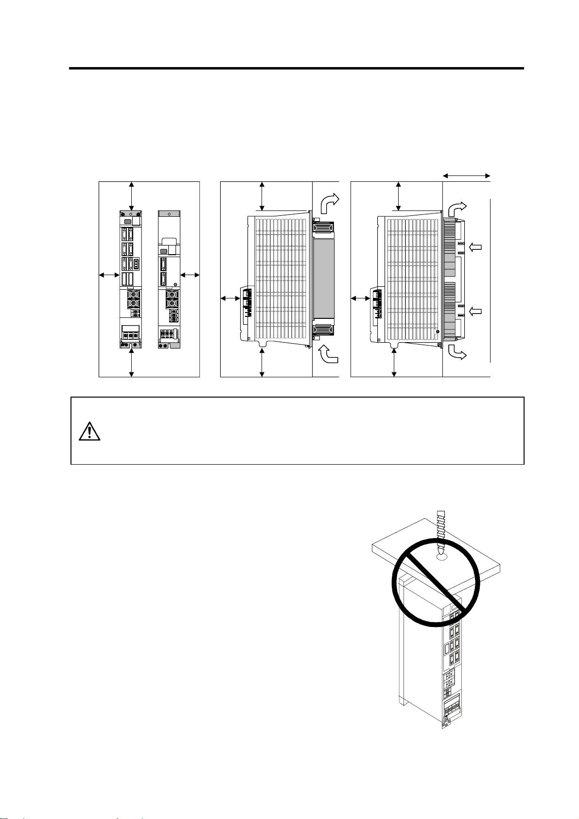
1-3-2 Installation direction and clearance
Wire each unit in consideration of the maintainability and the heat dissipation, as well as secure
sufficient space for ventilation.
75mm or more
10mm
or
more
100mm or
more
100mm or
more
10mm
or
more
50mm
or more
100mm or
more
100mm or
more
The ambient temperature condition for the power supply unit or the drive units is
55°C or less. Because heat can easily accumulate in the upper portion of the
CAUTION
units, give sufficient consideration to heat dissipation when designing the panel.
If required, install a fan in the panel to agitate the heat in the upper portion of the
units.
1-3-3 Prevention of entering of foreign matter
Treat the cabinet with the following items.
• Make sure that the cable inlet is dust and oil proof by using
packing, etc.
• Make sure that the external air does not enter inside by
using head radiating holes, etc.
• Close all clearances.
• Securely install door packing.
• If there is a rear cover, always apply packing.
• Oil will tend to accumulate on the top. Take special
measures such as oil-proofing to the top so that oil does
not enter the cabinet from the screw holds.
• After installing each unit, avoid machining in the periphery.
If cutting chips, etc., stick onto the electronic parts, trouble
may occur.
• When using the unit in an area with toxic gases or high
levels of dust, protect the unit with air purging (system to
blow clean air so that the panel's inner pressure is higher
than the outer pressure).
50mm
or more
100mm or
more
100mm or
more
1 - 11
Page 28
1. Installation
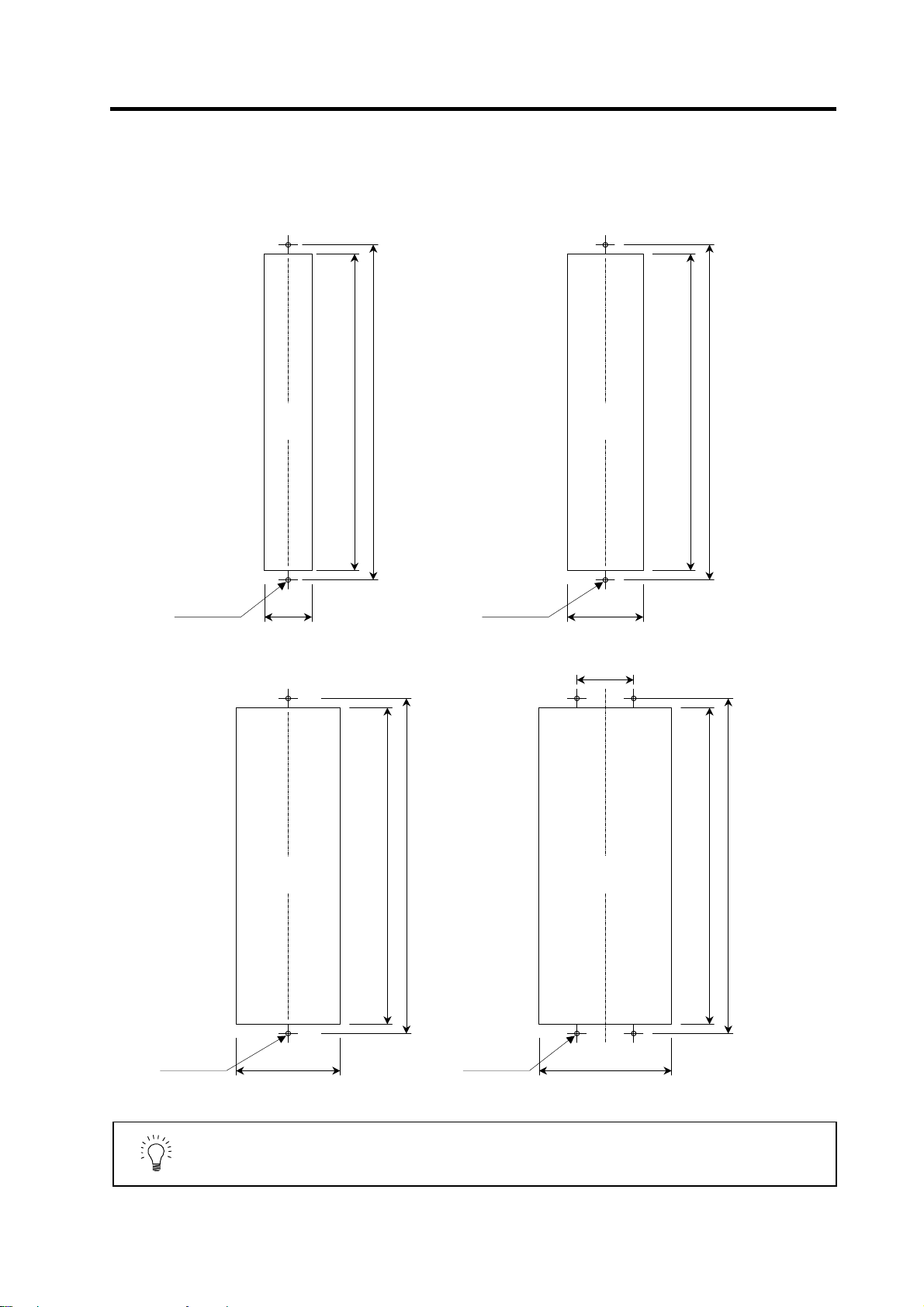
1-3-4 Panel installation hole work drawings (Panel cut drawings)
Prepare a square hole to match the unit width.
[Unit: mm]
Square
(Note 1)
2-M5 screw
Unit width: 60mm (only with fin)
hole
52
342
360
2-M5 screw
Square hole
(Note 1)
82
Unit width: 90mm
60
342
360
2-M5 screw
Square hole
(Note 1)
112
Unit width: 120mm Unit width: 150mm
342
360
1. Attach packing around the square hole to provide a seal.
POINT
2. A square hole does not need to be machined on the MDS-C1-V1-10 or
smaller, MDS-C1-V2-1010 or smaller and MDS-C1-SP-15 or smaller units.
1 - 12
4-M5 screw
Square hole
(Note 1)
142
342
360
Page 29

1. Installation
1-3-5 Heating value
Each heating value is calculated with the following values.
The values for the servo drive unit are for a stall output, and the values for the spindle drive unit are for
a continuous rated output. The value for the power supply unit includes the AC reactor's heating value.
Servo drive unit Spindle drive unit Power supply unit
Heating amount
Inside
panel
[W]
Outside
panel
Type
MDS-C1-
V1- 01 21 0 V2-0101 38 0 SP- 04 30 0 CV- 37 21 34
V1- 03 27 0 V2-0301 41 0 SP- 075 40 0 CV- 55 23 42
V1- 05 37 0 V2-0303 43 0 SP- 15 49 0 CV- 75 25 55
V1- 10 53 0 V2-0501 46 0 SP- 22 26 42 CV-110 26 99
V1- 20 25 66 V2-0503 52 0 SP- 37 28 51 CV-150 29 126
V1- 35 30 102 V2-0505 62 0 SP- 55 31 76 CV-185 33 162
V1- 45S 34 124 V2-1005 78 0 SP- 75 35 102 CV-220 35 175
V1- 45 37 148 V2-1010 96 0 SP-110 41 140 CV-260 40 220
V1- 70S 38 151 V2-2010 37 117 SP-150S 48 140 CV-300 46 274
V1- 70 50 234 V2-2020 41 137 SP-150 48 187 CV-370 54 346
V1- 90 56 275 V2-3510S 44 146 SP-185 62 280
V1-110 74 392 V2-3510 42 148 SP-220 65 301
V1-150 96 545 V2-3520S 48 165 SP-260 80 403
V2-3520 45 168 SP-300 98 522
V2-3535 51 209
V2-4520 52 214
V2-4535 57 249
V2-4545S 55 225
V2-4545 64 295
V2-7035 70 336
V2-7045 77 382
V2-7070S 65 300
V2-7070 90 468
V2-9090S 65 300
Type
MDS-C1-
Heating amount
[W]
Inside
panel
Outside
panel
Type
MDS-C1-
Heating amount
[W]
Inside
Outside
panel
panel
Type
MDS-C1-
Heating amount
[W]
Inside
panel
Outside
panel
Design the panel's heating value taking the actual axis operation (load rate) into
consideration. With a general machine tool, the servo drive unit's load rate is
POINT
approx. 50%, so the heating values inside the panel are half the values shown
above. (Excluding the power supply and spindle drive unit.)
(Example 1)
When using MDS-C1-CV-260, MDS-C1-SP[]-185 and MDS-C1-V2-3535
Total heating value = (40 + 220) + (62 + 280) + (51 + 209) = 862 [W]
Heating value in panel = (40) + (62) + (51 × 0.5) = 127.5 [W]
1 - 13
Page 30
1. Installation
1-3-6 Heat radiation countermeasures
In order to secure reliability and life, design the temperature in the panel so that the ambient
temperature of each unit is 55°C or less.
If heat accumulates at the top of the unit, etc., install a fan so that the temperature in the panel remains
constant.
(Note) Due to the structure, heat easily accumulates at the
top of the unit. Install a fan in the power distribution
panel to circulate the heat at the top of the unit.
(Inside panel)
Wind sp eed 2m/s or more
Fan
1 - 14
Page 31

r
1. Installation
Please refer to following method for heat radiation countermeasures.
W ≤ W1
∆T≤10°C
Calculate total heat radiation of each
mounted unit (W)
Calculate cabinet’s cooling capacity
Comparison of W and W1
Selection of heat exchanger
Collection of internal temperature rise
distribution data
(W1)
W>W1
Mounting design
Evaluation
∆T>10°C
Improvements
Completion
<Hypothetical conditions>
(1) Average temperature in cabinet : T ≤ 55°C
(2) Cabinet peripheral temperature : Ta ≤ 0°C to 45°C
(3) Internal temperature rise value : ∆T =T–Ta
<Supplement>
1) Refer to Specifications Manual, etc. for the heat
generated by each unit.
2) Enclosed cabinet (thin steel plate) cooling capacity
calculation equation
W1 = U × A × ∆T
U: 6W/m
4W/m
A: Effective heat radiation area (m
(Heat dissipation area in panel)
Sections contacting other objects are excluded.
∆T: Internal temperature rise value (10°C)
3) Points of caution for heat radiation countermeasures
when designing mounting state
• Layout of convection in panel
• Collect hot air at suction port in heat exchanger
cabinet.
4) Understanding the temperature rise distribution in the
panel
∆T (average value) ≤ 10°C
∆T
max (maximum value) ≤ 15°C
R (inconsistency) = (∆T
(Evaluate existence of heat spots)
2 ×
2
Examples of mounting and temperature measurement positions (reference)
z
Measurement position (example)
°C (with internal agitating fan)
× °C (without internal agitating fan)
max – ∆Tmin) ≤ 6°C
2
)
max= 10°C
Flow of air
Flow of air
Heat
exchange
Relay, etc
Unit
1 - 15
Page 32
w
1-4 Installing the spindle detector
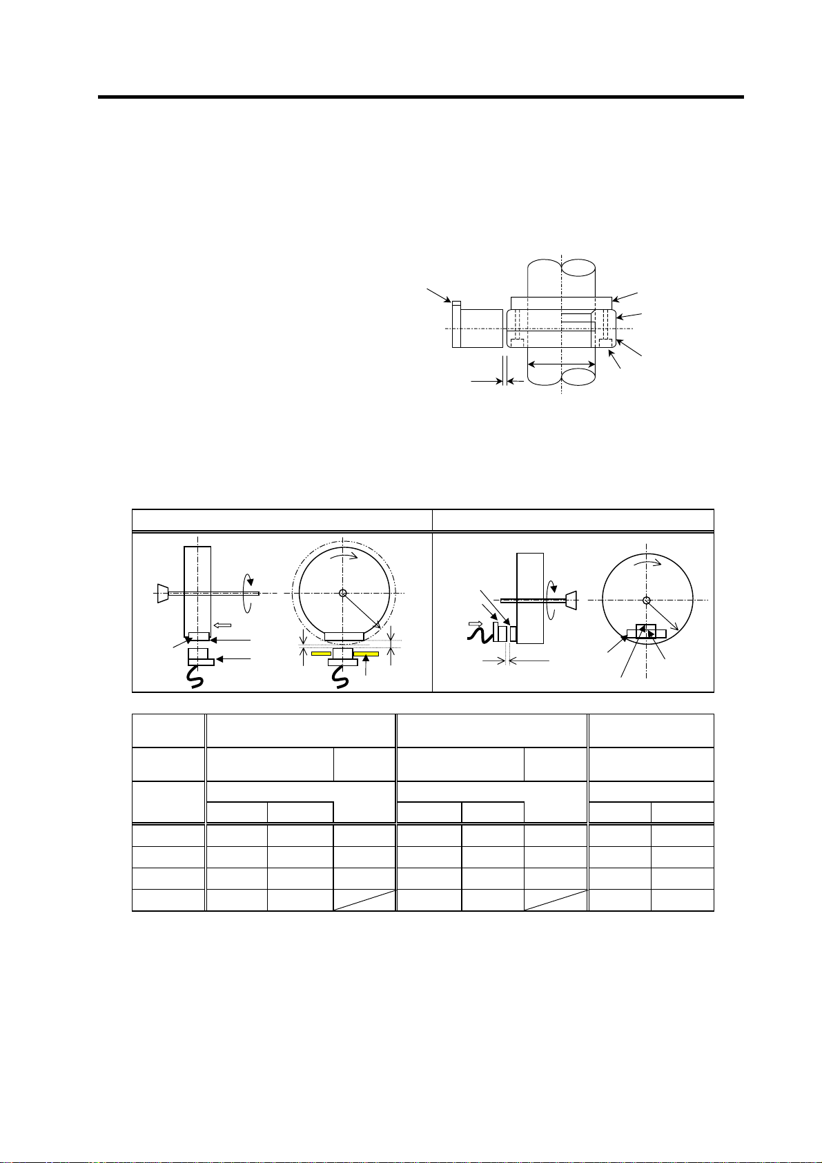
1-4-1 Magnetic sensor
(1) Installing the magnetic sensor
• Tolerance to shaft dimension should
be "h6" on the part for installing a
magnet.
• 2-øG hole can be used for positioning
of spindle and magnet.
• Magnet shall be installed as shown to
the right.
• Misalignment between sensor head
and magnetic center line shall be
within ±2mm.
• There is an NS indication on the side of
the cover. Install so that the reference
notch on the sensor head comes to the
case side.
(2) Gap between magnet and sensor
1. Installation
Reference notch
Spindle
G hole
h6
Gap
Reference drawing for magnet installation
Case
Cover
Spindle damping scre
Spindle
Magnet
Circumference installation
Direction of
rotation
Face A
Reference
hole
Reference
notch
Min. gap
Face A
R
NS
Max. gap
Mounting plate
Reference
hole
Reference
notch
Face B
Horizontal installation
Spindle
Face B
Gap
Magnet
Reference
notch
Direction of
rotation
N
S
R
Reference
hole
Magnet
model
Installation
direction
R (Radius)
mm
40 11.5±0.5 2.7±0.5 6.0±0.5 10.0±0.5 1.22±0.5 5.0±0.5 6.25±0.5 3.30±0.5
50 9.5±0.5 2.8±0.5 6.0±0.5 8.0±0.5 1.31±0.5 5.0±0.5 6.00±0.5 3.70±0.5
60 8.5±0.5 3.0±0.5 6.0±0.5 7.0±0.5 1.50±0.5 5.0±0.5 5.75±0.5 3.85±0.5
70 8.0±0.5 3.4±0.5 7.0±0.5 2.38±0.5 5.50±0.5 3.87±0.5
Max. value Min. value Max. value Min. value Max. value Min. value
BKO-C1810H03 BKO-C1730H06 BKO-C1730H09
Circumference
installation
Gap mm Gap mm Gap mm
Horizontal
installation
Circumference
installation
Horizontal
installation
Circumference
installation
1 - 16
Page 33
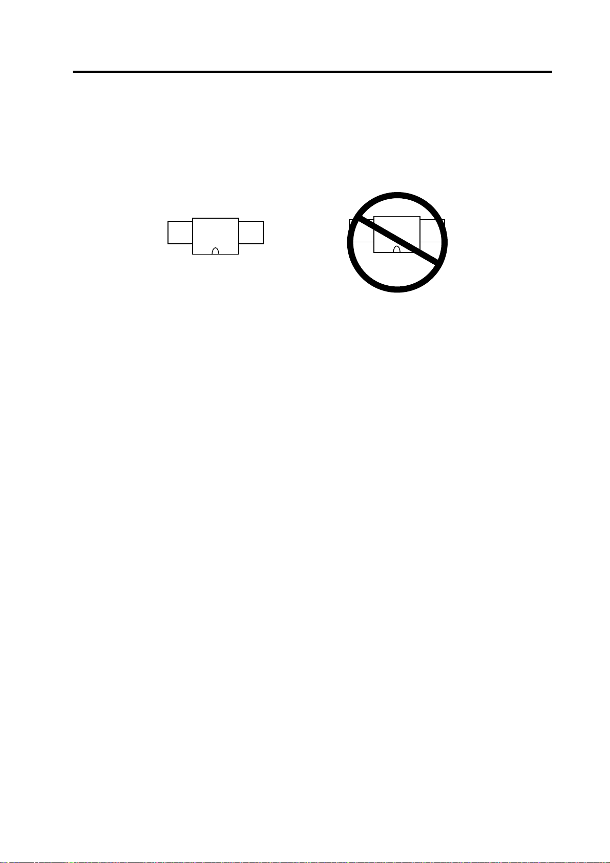
(3) Magnet and sensor installation directions
• Install so that the magnet's reference hole and sensor's reference notch are aligned.
(Standard/high-speed standards)
• Install so that the magnet's N pole comes to the left side when the sensor's reference notch is
faced downward. (High-speed compact/high-speed ring)
N S
Sensor
|
Reference notch
Magnet
(4) Cautions
[1] Do not apply impacts on the magnet. Do not install strong magnets near the magnet.
[2] Sufficiently clean the surrounding area so that iron chips and cutting chips do not adhere to the
magnet. Demagnetize the round disk before installing.
[3] Securely install the magnet onto the spindle with an M4 screw. Take measures to prevent
screw loosening as required.
[4] Balance the entire spindle rotation with the magnet installed.
[5] Install a magnet that matches the spindle's rotation speed.
[6] When installing the magnet onto a rotating body's plane, set the speed to 6,000r/min or less.
[7] Install so that the center line at the end of the head matches the center of the magnet.
[8] The BKO-C1730 is not an oil-proof product. Make sure that oil does not come in contact with
BNO-C1730 or BKO-C1810.
[9] When connecting to the spindle drive unit, wire so that the effect of noise is suppressed.
1. Installation
Sensor
S N
|
Reference notch
Magnet
1 - 17
Page 34

1. Installation
1-4-2 Spindle end detector
To maintain the detector life and performance, a flexible coupling should be used to couple the spindle
end detector and C-axis detector with the spindle.
Detector
Flexible coupling
Opposite detector shaft
side
Detector and coupling installation accuracy
Recommended coupling
Recommendation 1 Recommendation 2
Manufacturer Tokushu Seiko Eagle
Model Model M1 FCS38A
Resonance frequency 1374Hz 3515Hz
Position detection error 0.8×10⁻³° 1.2×10⁻³°
Tolerable speed 20000r/min 10000r/min
Mis-alignment
Outline dimensions
Core deviation 0.7mm 0.16mm
Angle displacement
Max. length 74.5mm 33mm
Max. diameter
Refer to the coupling catalog, etc., for details on the coupling.
0.02
0.02
1.5° 1.5°
ø57mm ø38mm
1 - 18
Page 35

r
1-4-3 Spindle end PLG
(1) Part configuration
The detector is configured of an encoder (Sensor section and PCB section) and detection gears.
The encoder section can be separated with an intermediate connector, but a type with the same
serial No. must be used in combination. The serial No. is indicated on the intermediate connector of
the sensor section and the output connector of the PCB section.
1. Installation
Sensor section
Detection
gears
Encoder
VR2
These are precision parts, and require care when handling. Do not apply an excessive force on the
sensor's detection surface, as this could result in faults. Do not pull and apply a load on the lead
wires. Make sure that foreign matters (iron chips, etc.) do not get on the sensor's detection surface
or detection gears. If any foreign matter should get on these parts, carefully remove while taking
care not to damage the parts. When handling the detection gears, take care not to damage or
deform the teeth.
(2) Installing the detection gears and sensor section
[1] Install the detection gears so that the first gear's teeth side (Z phase) face the sensor's lead
side.
[2] The detection gears and shaft or sleeve should be fixed with shrinkage fitting. Refer to the
following table for the shrinkage fitting values. The detection gears should be heated evenly
between 120 and 150°C using an electric furnace, etc.
Detection gear shrinkage fitting values
PCB section
VR4
VR1
VR3
VR5
Intermediate
connecto
Spindle end PLG
G
B
A
Z
Output connector
Serial No. indication
Detection gear specifications
Part type
MU1450N2137 128 ø52 ø40 0.02 to 0.04
MU1450N2730 180 ø72.8 ø55 0.03 to 0.055
MU1450N2236 256 ø103.2 ø80 0.03 to 0.055
MU1450N2534 512 ø205.6 ø140 0.05 to 0.085
No. of teeth
Outer diameter
(mm)
Inner diameter
(mm)
Shrinkage fitting
(mm)
1 - 19
Page 36

1. Installation
[3] Keep the deviation of the sensor center and detection
gear center to ±0.25mm or less. If the center deviation
cannot be directly measured, set so that the dimension
Sensor installation surface
Sensor installation seat
from the sensor installing surface to the edge of the
detection gears is 22.5±0.25mm.
Lead wire
[4] Keep the deflection of the outer diameter, when the
detection gears are installed on the shaft, to 0.02mm or
less.
[5] To remove a detection gear fixed with shrinkage fitting,
use the screw holes opened in the axial direction for
pulling (two M5 screw holes or two M8 screw holes), or
16.5mm
22.5mm
±.25mm
push the end with a jig. Carry out this work carefully.
Applying excessive force when pulling out the gears
could cause the inner diameter of the detection gears to
deform.
[6] Before reusing detection gears which have been
First tooth
removed, always measure the inner diameter dimensions,
and carefully check that the inner diameter is not
deformed, and that the sufficient tightening amount can
be secured. Do not reuse the detection gears if the inner
diameter is deformed, or if any abnormality such as
damage to the teeth is found.
[7] A notched fitting section and mounting screw hole are
provided on the machine as shown in the following
drawing. Contact the R section of the sensor installation
Installing the detection gears
seat against this and, install the sensor. The outline dimensions of the notched fitting section
are shown in the following table.
Installing the sensor section
Encoder part type
TS1860N2275 +0.200
TS1860N2276
TS1860N2777 +0.200
TS1860N2775
TS1860N2171 +0.200
TS1860N2174
TS1860N2571 +0.200
TS1860N2572
Sensor installation seat's
R dimensions (mm)
R35.5 ø71
R45 ø90
R61 ø122
R112.5 ø225
Notched fitting section's
outer diameter (mm)
+0.180
+0.180
+0.175
+0.170
1 - 20
Page 37

[
]
g
×
[8] With the sensor installation seat's R section butted against the notched fitting section, fix the
sensor installation seat with a mounting screw (M5 x 0.8 screws). A locking agent should be
applied on the mounting screw before it is tightened.
3.5mm or less
Butt the back side of the sensor installation
seat against here
Butt the R section of the sensor installation seat
a
ainst here
Notched section's
outer diameter
[9] When using the specifications (TS1860N2770,
TS1860N2776, TS1860N2183, TS1860N2187) with
installation plate (ring) for the sensor section,
provide a notched fitting section on the machine side
as shown on the right, and fit the sensor installation
plate's ø108H5 here. The gap does not need to be
adjusted when using the installation plate.
[10] Make sure that force is not constantly applied on the
sensor's lead wires.
(3) Installing the PCB section
[1] Install the PCB where it will not be subject to water or oil, etc.
[2] Drill two ø11mm or smaller installation seats, and fix the PCB with pan head screws (M5 × 0.8
screws).
[3] Provide a space of 25mm from the installation surface to treat the lead wires for the intermediate
connector.
[4] Select the minimum required length for the lead wires from the sensor to the intermediate
connector, and wire them as far away from other power wires as possible.
[5] Make sure that force is not constantly applied on the PCB lead wire connections.
[6] The check pins on the PCB could break if excessive force is applied.
1. Installation
2-M5
Outline
drawing
designated
dimensions
Shape of notched fitting section
0.8 screw
29mm
Notched section's
outer diameter
Unit: mm
-0.005
-0.020
ø 108
Installing the sensor with
Installation plate (ring)
1 - 21
Page 38

1. Installation
1-5 Noise measures
Noise includes "propagation noise" generated from the power supply or relay, etc., and propagated
along a cable causing the power supply unit or drive unit to malfunction, and "radiated noise"
propagated through air from a peripheral device, etc., and causing the power supply unit or drive unit to
malfunction.
Always implement these noise measures to prevent the peripheral devices and unit from malfunctioning.
The measures differ according to the noise propagation path, so refer to the following explanation and
take appropriate measures.
(1) General noise measures
• Avoid laying the drive unit's power line and signal wire in a parallel or bundled state. Always
separate these wires. Use a twisted pair shielded wire for the detector cable and signal wires
such as the communication cable connected with the NC, and accurately ground the devices.
• Use one-point grounding for the drive unit and motor.
• Accurately ground the AC reactor.
(2) Propagation noise measures
Take the following measures when noise generating devices are installed and the power supply
unit or drive unit could malfunction.
• Install a surge killer on devices (magnetic contacts, relays, etc.) which generate high levels of
noise.
• Install a power line filter in the stage before the power supply unit.
• Install a ferrite core on the signal wire.
• Ground the shield of the servo detector's cable with a cable clamp.
• Wire the spindle PLG detector cable away from other wires.
(3) Measures against radiated noise
The types of propagation paths of the noise and the noise measures for each propagation path are
shown below.
Noise generated from
drive unit
Airborne
propagation noise
Noise directly radiated
from drive unit
Path [1]
Magnetic induction
noise
Static induction
noise
Cable propagation
noise
Path [4]
and [5]
Noise radiated from
power line
Noise radiated from
servomotor/spindle motor
Noise propagated over
power line
Noise lead in from
grounding wire by
leakage current
Path [2]
Path [3]Path [6]
Path [7]
Path [8]
1 - 22
Page 39
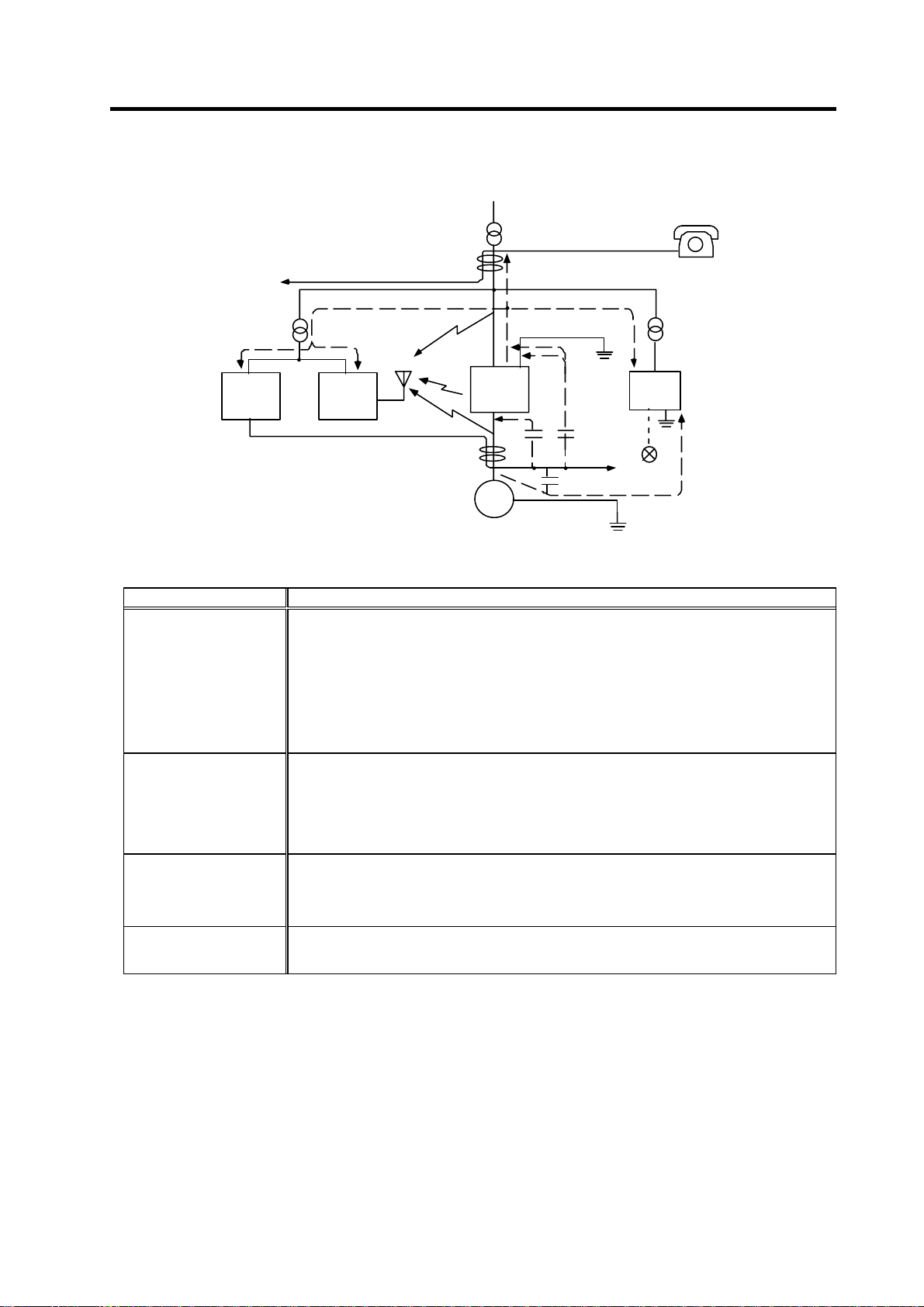
1. Installation
[5]
[7]
[2]
[1]
Drive
[3]
Servomotor
Spindle motor
Generated noise of drive system
unit
[4]
M
Instrument
[7]
Receiver
Noise propagation path Measures
When devices such as instrument, receiver or sensor, which handle minute signals and are easily
affected by noise, or the signal wire of these devices, are stored in the same panel as the drive
units and the wiring is close, the device could malfunction due to airborne propagation of the noise.
In this case, take the following measures.
[1] [2] [3]
[4] [5] [6]
[7]
[8]
(a) Install devices easily affected as far away from the drive units as possible.
(b) Lay devices easily affected as far away from the signal wire of the drive unit as possible.
(c) Avoid laying the signal wire and power line in a parallel or bundled state.
(d) Insert a line noise filter on the input/output wire or a radio filter on the input to suppress the
noise radiated from the wires.
(e) Use a shield wire for the signal wire and power line, or place in separate metal ducts.
If the signal wire is laid in parallel to the power line, or if it is bundled with the power line, the noise
could be propagated to the signal wire and cause malfunction because of the magnetic induction
noise or static induction noise. In this case, take the following measures.
(a) Install devices easily affected as far away from the drive unit as possible.
(b) Lay devices easily affected as far away from the signal wire of the drive unit as possible.
(c) Avoid laying the signal wire and power line in a parallel or bundled state.
(d) Use a shield wire for the signal wire and power line, or place in separate metal ducts.
If the power supply for the peripheral devices is connected to the power supply in the same sy stem
as the drive units, the noise generated from the power supply unit could back flow over the power
line and cause the devices to malfunction. In this case, take the following measures.
(a) Install a radio filter on the power supply unit's power line.
(b) Install a power filter on the power supply unit's power line.
If a closed loop is created by the peripheral device and drive unit's grounding wire, a leakage
current could flow and cause the device to malfunction.
In this case, change the device grounding methods and the grounding place.
[6]
[2]
Sensor
power
supply
Sensor
[8]
1 - 23
Page 40

2. Wiring and Connection
2-1 Part system connection diagram........................................................................................................ 2-3
2-2 Main circuit terminal block/control circuit connector ..........................................................................2-4
2-2-1 Names and applications of main circuit terminal block signals and control circuit connectors...2-4
2-2-2 Connector pin assignment ..........................................................................................................2-5
2-3 NC and drive unit connection............................................................................................................. 2-8
2-4 Motor and detector connection.........................................................................................................2-11
2-4-1 Connecting the servomotor.......................................................................................................2-11
2-4-2 Connecting the full-closed loop system.....................................................................................2-18
2-4-3 Connecting the synchronous control system............................................................................2-22
2-4-4 Connection of the spindle motor ...............................................................................................2-28
2-5 Connection of power supply.............................................................................................................2-33
2-5-1 Power supply input connection ..................................................................................................2-34
2-5-2 Connecting the grounding cable ............................................................................................... 2-37
2-5-3 Main circuit control .....................................................................................................................2-38
2-6 Wiring of the motor brake.................................................................................................................2-39
2-6-1 Wiring of the motor magnetic brake..........................................................................................2-39
2-6-2 Dynamic brake unit wiring.........................................................................................................2-41
2-7 Peripheral control wiring....................................................................................................................2-42
2-7-1 Input/output circuit wiring............................................................................................................2-42
2-7-2 Spindle coil changeover............................................................................................................2-43
2-7-3 Wiring of an external emergency stop.......................................................................................2-46
2 - 1
Page 41

2. Wiring and Connection
1. Wiring work must be done by a qualified technician.
2. Wait at least 15 minutes after turning the power OFF and check the voltage
with a tester, etc., before starting wiring. Failure to observe this could lead to
electric shocks.
3. Securely ground the drive units and servo/spindle motor.
DANGER
4. Wire the drive units and servo/spindle motor after installation. Failure to
observe this could lead to electric shocks.
5. Do not damage, apply forcible stress, place heavy items on the cables or get
them caught. Failure to observe this could lead to electric shocks.
6. Always insulate the power terminal connection section. Failure to observe
this could lead to electric shocks.
1. Correctly and securely perform the wiring. Failure to do so could result in
runaway of the servo/spindle motor or injury.
2. Do not mistake the terminal connections.
Failure to observe this item could lead to ruptures or damage, etc.
3. Do not mistake the polarity ( + ,
- ). Failure to observe this item could lead to
ruptures or damage, etc.
4. Do not mistake the direction of the diodes for the surge absorption installed
on the DC relay for the motor brake and contactor (magnetic contactor)
control. The signal might not be output when a failure occurs.
Servo drive unit
Servo drive unit
COM
COM
(24VDC)
(24VDC)
CAUTION
Control output signal
Control output signal
RA
RA
5. Electronic devices used near the drive units may receive magnetic
obstruction. Reduce the effect of magnetic obstacles by installing a noise
filter, etc.
6. Do not install a phase advancing capacitor, surge absorber or radio noise
filter on the power line (U, V, W) of the servo/spindle motor.
7. Do not modify this unit.
8. The half-pitch connector (CN1A, etc.) on the front of the drive units have the
same shape. If the connectors are connected incorrectly, faults could occur.
Make sure that the connection is correct.
9. When grounding the motor, connect to the protective grounding terminal on
the drive units, and ground from the other protective grounding terminal.
(Use one-point grounding) Do not separately ground the connected motor
and drive unit as noise could be generated.
2 - 2
Page 42

r
r
r
2. Wiring and Connection
2-1 Part system connection diagram
Mitsubishi CNC
(CSH21)
No-fuse
breaker
R
S
T
: Main circuit
SV1,2
reactor
Ground
Breaker
AC
SH21 cable
External emergency
stop input
Contacto
MC
CN4
CN9
CN23
L1
TE1
L2
L3
MC1
L11
L21
TE3
TE2
L+
L-
Spindle drive unitPower supply unit
CN1A
SH21 cable
CN4
CN9
L+
L-
L11
L21
TE2
TE3
TE1
CN1B
CN8
CN7
CN6
CN5
U
V
W
Battery unit
CN1A
Spindle
motor
PLG
Servo drive unit
CN1A
CN4
CN9
CN20
TE1
L+
TE2
L-
L11
TE3
L21
CN1B
CN3M
CN3L
CN2L
CN2M
MU
MV
MW
LU
LV
LW
T ool end detecto
T ool end detecto
Servo
motor
Motor end
detector
Servo
motor
Motor end
detector
: Control circuit
Ground
Ground
(Note 1) The total length of the SH21 cable must be within 30m.
(Note 2) The connection method will differ according to the used motor.
(Note 3) When not using a battery unit, connect the terminal connector (R-TM).
(Note 4) The main circuit (
) and control circuit ({) are safely separated.
Ground
2 - 3
Page 43

2. Wiring and Connection
2-2 Main circuit terminal block/control circuit connector
2-2-1 Names and applications of main circuit terminal block signals and control circuit
connectors
The following table shows the details for each terminal block signal.
Name Signal name Description
L1 . L2 . L3
L11 L21
MC1
U . V . W
LU . LV . LW
MU . MV . MW
Main circuit power
supply
Control circuit power
supply
Contactor control
Motor output
(Single-axis unit)
Motor output
(Dual-axis unit)
Protective grounding
(PE)
Main circuit power supply input terminal
Connect a 3-phase 200VAC/200 to 230VAC, 50/60Hz power supply.
Control circuit power supply input terminal
Connect a single-phase 200VAC/200 to 230VAC, 50/60Hz power supply.
Contactor control terminal
The MC1 terminal has the same phase as L21. Connect to a different phase than the
phase connected to L21.
Servo/spindle motor power output terminal
The servo/spindle motor power terminal (U, V, W) is connected.
Servo motor power output terminal (L-axis/M-axis)
The servo/spindle motor power terminal (U, V, W) is connected.
Grounding terminal
The servomotor/spindle motor grounding terminal is connected and grounded.
1. Always use one AC reactor per power supply unit. Failure to observe this
could lead to unit damage.
CAUTION
2. When sharing a breaker for several power supply units, of a short-circuit
fault occurs in a small capacity unit, the breaker could trip. This can be
hazardous, so do not share the breaker.
3. Be sure to use the breaker of proper capacity for each power supply unit.
2 - 4
Page 44

2-2-2 Connector pin assignment
2. Wiring and Connection
CAUTION
Do not apply a voltage other than that specified in Instruction Manual on each
terminal. Failure to observe this item could lead to rupture or damage, etc.
(1) Main circuit terminal block
Power supply unit
Terminal
Terminal
position
Unit
MDS-C1-CV-37 to 75 MDS-C1-CV-110 to 370
[2]
[3]
[1]
[2]
[3]
[1]
[4]
U V W
[1] TE1
Compatible unit CV-37 to 75
Screw size
Tightening torque
[2] TE2
[3] TE3
Terminal specification/Pin assignment
Compatible unit CV-37 to 75
[4]
Screw size M4
Tightening torque 2.0Nm
L+
L-
L11
L21
MC1
U V W
Compatible unit CV-110 to 185 CV-220 to 370
M4
1.6Nm
Compatible unit CV-37 to 370
Screw size
Tightening torque
Compatible unit CV-37 to 75 CV-110 to 370
Screw size M4 M4
Tightening torque 2.0Nm 1.6m
Screw size
Tightening torque
M6
5.0Nm
M5 M8
3.37Nm 13.2Nm
Compatible unit CV-110 to 185 CV-220 to 370
Screw size M5 M8
Tightening torque 3.37Nm 13.2Nm
[4]
2 - 5
Page 45

[2] [3]
[1]
[4]
[2]
[3]
[2]
[3]
[1]
[4]
[2]
[3]
[1]
[4]
Servo/spindle drive unit
Terminal
Unit
Terminal
position
MDS-C1-V1-10 and
smaller
MDS-C1-SP-15 and
smaller
2. Wiring and Connection
MDS-C1-V1-20 and
larger
MDS-C1-SP-22 and
larger
[1]
[4]
MDS-C1-V2-1010 and
smaller
MDS-C1-V2-2010 and
larger
MU MV MW
MU MV MW
U V W
[1] TE1
[2] TE2
Terminal specification/Pin assignment
[3] TE3
[4]
U V W
LU LV LW
V1- 01 to 35 45S,45 to 90 110 to 150
Compatible unit
Screw size M4 M5 M8
Tightening torque 2.0Nm 3.2Nm 13.2Nm
V2- 0101 to 9090S SP- 04 to 37 55 to 185 220 to 300
L+
L-
L11
L21
The PE screw size is the same as TE1.
Compatible unit All V1/V2/SP
Screw size M6
Tightening torque 5.0Nm
Compatible unit All V1/V2/SP
Screw size M4
Tightening torque 2.0Nm
LU LV LW
2 - 6
Page 46

p
[1] [3] [5] [2]
[4]
[9]
[6]
[1]
[3]
[5]
[2]
[4]
[9]
[6]
[8]
[7]
(2) Control circuit connector
position
[1] CN1A
[2] CN1B
[3] CN9
[4] CN4
[5] CN2L
[6] CN3L
[7] CN2M
[8] CN2M
Unit
Terminal
Connector
ecifications
2. Wiring and Connection
MDS-C1-V1 MDS-C1-V2
Pin No.
No.1
No.10
No.11
No.20
Pin No.
Connector s
[9] CN20
No.1
No.2
No.3
(Note) The [5] and [6] connector names differ for the MDS-C1-V1 unit. (CN2L, CN3L → CN2, CN3)
2 - 7
Page 47

(
)
(
2. Wiring and Connection
2-3 NC and drive unit connection
The NC bus cables are connected from the NC to each drive unit so that they run in a straight line from
the NC to the terminal connector (battery unit). And up to 7 axes can be connected per system.
Note that the number of connected axes is limited by the NC.
CAUTION
POINT
(1) When using one power supply unit
Connect the largest-capacity spindle drive unit to the final axis of the NC communication bus in
order to control the power supply unit. The spindle drive unit must be installed adjacent to the power
supply unit. In the system with servo only, a servo drive unit for controlling unbalance axis must be
installed in the same manner in the same way.
< Connection >
CN1A : CN1B connector on NC or previous stage's drive unit
CN1B : CN1A connector on next stage's drive unit or terminal connector (battery unit)
CN4 : Connector for communication between power supply unit (master side) and drive unit
Refer to the
instruction manual
of each NC for
details.
Connected
to the NC
Wire the SH21 cable between the NC and drive unit so that the distance
between the NC and terminal connector (battery unit) is within 30m.
Axis Nos. are determined by the rotary switch for setting the axis No. (Refer to
section "3-1-1 Setting the rotary switch".) The axis No. has no relation to the
order for connecting to the NC.
MDS-C1-SP
4th axis (final axis)
Connect to the battery unit with a
terminal connector or SH21 cable.
CN1A
CN1B
MDS-C1-CV MDS-C1-V2
SH21 cable
1st/2nd axis
CN1A
CN1B CN1A
MDS-C1-V1
3rd axis
CN1B
CN1A/CN1B
Pin No.
No.1
No.10
Name
GND
1
2
3
4
GND
5
GFO
6
EMG
7
8
BAT
9
P5
10
Max. length of 30m from the NC to terminal connector or battery unit.
RD
AL
SD
+5V)
No.11
No.20
11
12
13
14
15
16
17
18
19
20
Name
GND
RD*
AL
SD*
GND
GFO
EMG*
+5V
P5
Connection when using one power supply unit
2 - 8
CN4
CN4
Page 48

2. Wiring and Connection
(2) When using two or more power supply units within a single NC communication bus system
Two or more power supply units may be required within a single NC communication bus system if
the spindle drive unit capacity is large. The drive unit receiving power (L+, L-) from each power
supply unit must always have NC communication bus connection at the NC side of each power
supply unit. In the NC communication bus connection example below, power supply [1] cannot
supply power (L+, L-) to the 5th axis servo drive unit.
For basic connection information, refer to "(1) When using one power supply unit".
Connected
to the NC
CN1A
Power
cannot be
supplied
MDS-C1-V1
5th axis
CN1B
MDS-C1-V2
1st/2nd axis
CN1A
SH21 cable
Connections when using two power supply units within a single NC communication bus system
CN1B CN1A
MDS-C1-V2
3rd/4th axis
(CV control axis)
CN1B
CN4
MDS-C1-CV
[1]
CN4
The drive unit receiving power (L+, L-) from each power supply unit must always
CAUTION
have NC communication bus connection at the NC side of each power supply
unit.
MDS-C1-SP
6th axis
(CV control axis)
CN1A
CN1B
CN4
MDS-C1-CV
[2]
CN4
2 - 9
Page 49

2. Wiring and Connection
(3) When using one power supply shared unit by two NC communication bus systems
In systems employing a number of small-capacity drive units, a single power supply unit can be
shared by two NC communication bus systems. In this case, a power supply control axis must be
set for each axis of each NC communication bus.
For basic connection information, refer to "(1) When using one power supply unit".
Connected to the NC
(System No.1)
Connected to the NC
(System No.2)
Connections when using one power supply shared by two NC communication bus systems
CAUTION
MDS-C1-V2
1st/2nd axis
CN1A
MDS-C1-V2
8th/9th axis
CN1A
MDS-C1-V2
3rd/4th axis
CN1B CN1A
MDS-C1-V1
CN1B CN1A
CN1B
10th axis
CN1B
MDS-C1-V2
5th/6th axis
CN1A
MDS-C1-SP
11th axis
CN1A
CN1B
CN1B
MDS-C1-V1
7th axis
(CV control axis)
CN1A
(CV control axis)
CN1A
CN1B
CN4
MDS-C1-SP
12th axis
CN1B
CN4
MDS-C1-CV
(shared)
CN4
If the two NC communication bus systems include a spindle drive unit, connect
the power supply unit's CN4 connector to the CN4 connector of the largestcapacity spindle drive unit. If there is no spindle drive unit, connect to the
unbalance-axis servo drive unit.
CN9
2 - 10
Page 50

(
)
(
r
2. Wiring and Connection
2-4 Motor and detector connection
2-4-1 Connecting the servomotor
(1) Connecting the HC52(B)/HC102(B)/HC152(B)/HC53(B)/HC103(B)/HC153(B)/HC103R(B)
/HC153R(B)/HC203R(B)
Detector connector
MS3102A22-14P
K
J
H
Pin Name
A
B
C
D
E BAT
F
G
H SD
J SD*
K RQ
L RQ*
M
N FG
P
R LG(GND)
S P5(+5V)
T
U
V
Option cable : CNV12
(Refer to Appendix 1 for details
L
N
R
S
E
on the cable treatment.)
Max. 30m
MDS-C1-V1
CN2
U VW
Power connecto
CE05-2A22-23P
A
G
H
F
E
D
B1 and B2 are brake terminals.
(Only for motor with brakes)
These are 24VDC, and have no
polarity.
Detector connector : CN2
Pin No.
No.1
No.10
Pin
Name
1
LG
2
3
4
5
6
SD
7
RQ
8
9
BAT
Name
U
V
W
Grounding
B1
B2
P5
+5V)
10
Power wire and grounding wire
(Refer to Specification manual for details
on selecting the wire.)
Pin
A
B
C
D
B
E
F
C
G
H
Pin
11
12
13
14
15
16
17
18
19
20
No.11
No.20
Name
P5(+5V)
P5
LG
SD*
RQ*
+5V
2 - 11
Page 51

(
)
(
A
2. Wiring and Connection
(2) Connecting the HC202(B)/HC352(B)/HC452(B)/HC203(B)/HC353(B)
MDS-C1-V1
Detector connector
MS3102A22-14P
L
K
J
H
Pin Name
A
B
C
D
E BAT
F
G
H SD
J SD*
K RQ
L RQ*
M
N FG
P
R LG(GND)
S P5(+5V)
T
U
V
Brake connector
MS3102A10SL-4P
B
These are 24VDC, and have
no polarity.
N
R
Pin
A
B
S
E
Name
Option cable : CNV12
(Refer to Appendix 1 for details
on the cable treatment.)
Max. 30m
B1
B2
CN2
Motor brake wiring
(Refer to section
"2-6 Wiring of the motor
brake" for details.)
U V W
Power connector
CE05-2A24-10P
A
F
G
E
D
B
C
Detector connector : CN2
Pin No.
No.1
No.10
Pin
Name
1
LG
2
3
4
5
6
SD
7
RQ
8
9
BAT
Name
U
V
W
Grounding
P5
+5V)
10
Power wire and grounding wire
(Refer to Specification manual for details
on selecting the wire.)
Pin
A
B
C
D
E
F
G
Pin
11
12
13
14
15
16
17
18
19
20
No.11
No.20
P5(+5V)
P5
Name
LG
SD*
RQ*
+5V
2 - 12
Page 52

(
)
(
A
2. Wiring and Connection
(3) Connecting the HC353R(B)/HC503R(B)
MDS-C1-V1
Detector connector
MS3102A22-14P
L
K
J
A
B
C
D
E BAT
G
H SD
K RQ
M
N FG
P
R LG(GND)
S P5(+5V)
U
V
N
H
R
S
E
Pin Name
F
J SD*
L RQ*
T
Option cable : CNV12
(Refer to Appendix 1 for details
on the cable treatment.)
Max. 30m
CN2
U V W
Power connector
CE05-2A24-10P
F
G
E
C
D
Detector connector : CN2
Pin No.
No.1
No.10
Pin
Name
1
LG
2
3
4
5
6
SD
7
RQ
8
9
BAT
Name
U
V
W
Grounding
B1
B2
P5
+5V)
10
Power wire and grounding wire
(Refer to Specification manual for details
on selecting the wire.)
Pin
A
B
C
D
B
E
F
G
Pin
11
12
13
14
15
16
17
18
19
20
No.11
No.20
P5(+5V)
P5
Name
LG
SD*
RQ*
+5V
B1 and B2 are brake terminals.
(Only for motor with brakes)
These are 24VDC, and have no polarity.
2 - 13
Page 53

(
)
(
A
A
2. Wiring and Connection
(4) Connecting the HC702(B)/HC902(B)/HC453(B)/HC703(B)
MDS-C1-V1
Detector connector
MS3102A22-14P
L
K
J
Pin Name
A
B
C
D
E BAT
F
G
H SD
J SD*
K RQ
L RQ*
M
N FG
P
R LG(GND)
S P5(+5V)
T
U
V
N
H
R
S
E
Option cable : CNV12
(Refer to Appendix 1 for details
on the cable treatment.)
Max. 30m
Motor brake wiring
(Refer to section
"2-6 Wiring of the
motor brake" for
details.)
CN2
U V W
Power connector
CE05-2A32-17P
D
Brake connector
MS3102A10SL-4P
Name
Pin
B
These are 24VDC, and have
no polarity.
B1
A
B2
B
Detector connector : CN2
Pin No.
No.1
No.10
Pin
Name
1
LG
2
3
4
5
6
SD
7
RQ
8
9
BAT
Name
U
V
W
Grounding
P5
+5V)
10
Power wire and grounding wire
(Refer to Specification manual for details
on selecting the wire.)
Pin
A
B
C
D
BC
Pin
11
12
13
14
15
16
17
18
19
20
No.11
No.20
P5(+5V)
P5
Name
LG
SD*
RQ*
+5V
2 - 14
Page 54

(
)
(
A
(5) Connecting the HA053N/HA13N
Detector connector
MS3102A22-14P
L
K
J
Pin Name
A
B
C
D
E BAT
F
G
H SD
K RQ
L RQ*
M
N FG
P
R LG(GND)
S P5(+5V)
T
U
V
N
H
R
S
E
J SD*
Option cable : CNV12
(Refer to Appendix 1 for details
on the cable treatment.)
Max. 30m
2. Wiring and Connection
MDS-C1-V1
CN2
U V W
Power connector
MS3102A18-12
F
E
C
D
Detector connector : CN2
Pin No.
No.1
No.10
Pin
Name
1
LG
2
3
4
5
6
SD
7
RQ
8
9
BAT
Name
U
V
W
Grounding
P5
+5V)
10
Power wire and grounding wire
(Refer to Specification manual for details
on selecting the wire.)
Pin
A
B
C
D
B
E
F
Pin
11
12
13
14
15
16
17
18
19
20
No.11
No.20
Name
SD*
RQ*
P5(+5V)
P5
LG
+5V
2 - 15
Page 55

(
)
(
A
A
(6) Connecting the HA23N(B)/HA33N(B)
Detector connector
MS3102A22-14P
L
K
J
Pin Name
N
H
R
S
E
A
B
C
D
E BAT
F
G
H SD
J SD*
K RQ
L RQ*
M
N FG
P
R LG(GND)
S P5(+5V)
T
U
V
Option cable : CNV12
(Refer to Appendix 1 for details
on the cable treatment.)
Max. 30m
Motor brake wiring
(Refer to section
"2-6 Wiring of the motor
brake" for details.)
Brake connector
MS3102A10SL-4P
Name
Pin
B
These are 24VDC, and have
no polarity.
B1
A
B2
B
2. Wiring and Connection
MDS-C1-V1
CN2
U V W
Power connector
MS3102A18-12
F
E
C
D
Detector connector : CN2
Pin No.
No.1
No.10
Pin
Name
1
LG
2
3
4
5
6
SD
7
RQ
8
9
BAT
Name
U
V
W
Grounding
P5
+5V)
10
Power wire and grounding wire
(Refer to Specification manual for details
on selecting the wire.)
Pin
A
B
C
D
B
E
F
Pin
11
12
13
14
15
16
17
18
19
20
No.11
No.20
Name
SD*
RQ*
P5(+5V)
P5
LG
+5V
2 - 16
Page 56

(
)
(
A
2. Wiring and Connection
(7) Connecting the HA-LF11K2(B)-S8/HA-LF15K2(B)-S8
MDS-C1-V1
Detector connector
MS3102A22-14P
L
K
J
A
B
C
D
E BAT
G
H SD
K RQ
M
N FG
P
R LG(GND)
S P5(+5V)
U
V
N
H
R
S
E
Pin Name
F
J SD*
L RQ*
T
Option cable : CNV12
(Refer to Appendix 1 for details
on the cable treatment.)
Max. 30m
CN2
U V W
Detector connector : CN2
Pin No.
No.1
No.10
Pin
Name
1
LG
2
3
4
5
6
SD
7
RQ
8
9
BAT
P5
+5V)
10
Power wire and grounding wire
(Refer to Specification manual for details
on selecting the wire.)
Motor brake wiring
(Refer to section
"2-6 Wiring of the motor
brake" for details.)
Pin
11
12
13
14
15
16
17
18
19
20
No.11
No.20
Name
RQ*
P5(+5V)
P5
LG
SD*
+5V
Brake connector
MS3102A10SL-4P
Pin
B
These are 24VDC, and have
no polarity.
A
B
Name
B1
B2
2 - 17
Page 57

(
(
2. Wiring and Connection
2-4-2 Connecting the full-closed loop system
Refer to section "2-4-1 Connecting the servomotor" for details on connecting the each motor type.
(1) Connecting the ball screw end detector
Detector connector : CN3
Pin No.
Max. 30m
CNV12
CN2
MDS-C1-V1
CN3
Pin
10
1
2
3
4
5
6
7
8
9
No.1
No.10
Name
LG
SD
RQ
BAT
+5V)
P5
CNV13
Pin
11
12
13
14
15
16
17
18
19
20
No.11
No.20
Name
LG
SD*
RQ*
P5(+5V)
P5
+5V)
U V W
Table
Servomotor
2 - 18
Page 58

(
(
2. Wiring and Connection
(2) Connecting the linear scale (for oblong wave data output)
Detector connector : CN3
Pin No.
No.1
No.11
Max. 30m
CNV12
MDS-C1-V1
CN2 CN3
Pin
10
No.10
Name
1
LG
2
A
3
B
4
Z
5
6
7
8
9
BAT
+5V)
P5
Pin
11
12
13
14
15
16
17
18
19
20
No.20
Name
P5(+5V)
P5
LG
A*
B*
Z*
+5V)
U V W
Table
Servomotor
Linear scale
2 - 19
Page 59

(
(
2. Wiring and Connection
(3) Connecting the linear scale (for serial data output)
Detector connector : CN3
Pin No.
No.1
No.11
Max. 30m
CNV12
MDS-C1-V1
CN2 CN3
Pin
10
No.10
Name
1
LG
2
3
4
5
6
SD
7
RQ
8
9
BAT
+5V)
P5
Pin
11
12
13
14
15
16
17
18
19
20
No.20
Name
P5(+5V)
P5
LG
SD*
RQ*
+5V)
U V W
Table
Servomotor
Linear scale
2 - 20
Page 60

(
(
2. Wiring and Connection
(4) Connecting the linear scale (for analog output)
Detector connector : CN3
Pin No.
No.1
No.11
Max. 30m
CNV12
MDS-C1-V1
CN2 CN3
Pin
10
No.10
Name
1
LG
2
3
4
5
6
SD
7
RQ
8
9
BAT
+5V)
P5
CNL3-H2
CON1 CON2
converter unit
Pin
11
12
13
14
15
16
17
18
19
20
Detector
MDS-B-HR
No.20
Name
P5(+5V)
P5
LG
SD*
RQ*
+5V)
CON4
CON3
U V W
CNLH3
Servomotor
Table
Linear scale
2 - 21
Page 61

2. Wiring and Connection
2-4-3 Connecting the synchronous control system
The connection method and motor/encoder type (SV025) setting combinations for each synchronous
control system are shown in the table below. For power supply connections for each servomotor type,
refer to "2-4-1 Connecting the servomotor".
Position command
synchronous control
Speed command
synchronous control
Current command
synchronous control
Semi-closed system
(Only for motor side detector)
The operation is controlled with position commands from the NC, so there are no special
connections.
A normal value is set for the SV025 setting.
(1) When using MDS-C1-V1 drive
unit
(2) When using MDS-C1-V2 drive
unit
(For machine side detector + motor side detector)
(3) When using MDS-C1-V1 drive unit
(Only compatible with serial output linear scale)
MDS-C1-V2 drive unit
(4-1) When using serial output linear scale
(4-2) When using analog output linear scale
Some control restrictions may apply when using speed and current command synchronous control,
depending on the servo drive unit's control mode and control system configuration. Refer to the
following table for details.
List of control systems and supported synchronous control (high-gain specifications)
Full-closed system
Control system type Controlled by MDS-C1-V2 Co n t r o l l e d b y M D S - C 1 - V 1 x 2 U n i t s
Incremental control
Semi-closed
system
Absolute position
control
Incremental control
Full-closed
system (Note)
Absolute position
control
(Note) Pulse output linear scale is not supported.
List of control systems and supported synchronous control (standard specifications)
Control system type Controlled by MDS-C1-V2 C o n t r o l l e d b y M D S - C 1 - V 1 x 2 U n i t s
Incremental control Not supported Not supported
Semi-closed
system
Full-closed
system
Absolute position
control
Incremental control Not supported Not supported
Absolute position
control
1. Incremental control is only supported when using 2-axis servo drive unit. If
POINT
two 1-axis units are used, be sure to carry out absolute position control.
2. When synchronous control operation is carried out at 2-axis servo drive unit,
the L-axis is the master axis, and the M-axis is the slave axis.
Speed command
synchronous control
Current command
synchronous control
Speed command
synchronous control
Current command
synchronous control
Speed command
synchronous control
Current command
synchronous control
Speed command
synchronous control
Current command
synchronous control
Not supported
Not supported Not supported
Not supported
Speed command
synchronous control
Current command
synchronous control
Not supported
Speed command
synchronous control
Speed command
synchronous control
Current command
synchronous control
2 - 22
Page 62

2. Wiring and Connection
(1) Connection for semi-closed synchronous control (when using MDS-C1-V1 drive unit)
Slave axis
Master axis
Detector cable
MDS-C1-V1
(Slave axis)
CN3
MDS-C1-V1
(Master axis)
CN2
CNV12
MDS-B-SD
Signal distribution unit
CN2CN2
SH21
SH21
CN2A
CN2B
Parameter settings
No. Abbrev. Parameter name Description
SV025 MTYP Motor/detector type
(Note) A system in which two MDS-C1-V1 unit are used is not compatible with incremental system.
Set the detector type. The value determined for each motor type is input to “xx” in the
following table.
Speed command
synchronous
control
Current
command
synchronous
control
OSE104/OSE105 OSA104 OSA105
Not compatible
Not compatible
Motor end detector type
Master axis =11xx
Slave axis =C1xx
Master axis =11xx
Slave axis =CCxx
Master axis =22xx
Slave axis =C2xx
Master axis =22xx
Slave axis =CCxx
2 - 23
Page 63

2. Wiring and Connection
(2) Connection for semi-closed synchronous control (when using MDS-C1-V2 drive unit)
Slave axis
Master axis
MDS-C1-V2
CN2L
CN2M
Parameter settings
No. Abbrev. Parameter name Description
SV025 MTYP Motor/detector type
Set the detector type. The value determined for each motor type is input to “xx” in the
following table.
Speed
command
synchronous
control
Current
command
synchronous
control
OSE104 OSA104 OSE105/OSA105
Master axis =00xx
Slave axis =C0xx
Master axis =00xx
Slave axis =CCxx
Motor end detector type
Detector cable
CNV12
Master axis =11xx
Slave axis =C1xx
Master axis =11xx
Slave axis =CCxx
Master axis =22xx
Slave axis =C2xx
Master axis =22xx
Slave axis =CCxx
2 - 24
Page 64

2. Wiring and Connection
(3) Connection for full-closed synchronous control
(when using MDS-C1-V1 drive unit and serial output linear scale)
Linear scale
MDS-C1-V1
(Slave axis)
CN2
CN3 CN2 CN3
MDS-C1-V1
(Master axis)
Slave axis
Master axis
Detector cable
CNV12
MDS-B-SD
Signal distribution
unit
CN3
SH21
CN3
SH21
CN3
Parameter settings
No. Abbrev. Parameter name Description
SV025 MTYP Motor/detector type
(Note1) A system in which two MDS-C1-V1 unit are used is not compatible with incremental system.
(Note2) The full-closed system in which two MDS-C1-V1 units are used is not compatible with current command synchronous
control.
Set the detector type. The value determined for each motor type is input to “xx” in the
following table.
Speed command
synchronous
control
Current
command
synchronous
control
OSE104/OSE105 OSA104 OSA105
Not compatible
Motor end detector type
Master axis =A1xx
Slave axis =D1xx
Not compatible
Master axis =A2xx
Slave axis =D2xx
2 - 25
Page 65

2. Wiring and Connection
(4-1) Connection for full-closed synchronous control
(when using MDS-C1-V2 drive unit and serial output linear scale)
Linear scale
MDS-C1-V2
Slave axis
Master axis
Detector cable
CNV12
CN2L
CN2M
CN3L
Parameter settings
No. Abbrev. Parameter name Description
SV025 MTYP Motor/detector type
Set the detector type. The value determined for each motor type is input to “xx” in the
following table.
Speed command
synchronous
control
Current
command
synchronous
control
OSE104 OSA104 OSE105/OSA105
Master axis =A0xx
Slave axis =D0xx
Master axis =A0xx
Slave axis =DExx
Motor end detector type
Master axis =A1xx
Slave axis =D1xx
Master axis =A1xx
Slave axis =DExx
Master axis =A2xx
Slave axis =D2xx
Master axis =A2xx
Slave axis =DExx
2 - 26
Page 66

2. Wiring and Connection
(4-2) Connection for full-closed synchronous control
(when using MDS-C1-V2 drive unit and analog output linear scale)
Linear scale
MDS-C1-V2
Slave axis
Master axis
Detector cable
CNV12
CN2L
CN2M
CN3L
CON3CON4
Detector
Converter
unit
MDS-B-HR
CON1CON2
Parameter settings
No. Abbrev. Parameter name Description
SV025 MTYP Motor/detector type
Set the detector type. The value determined for each motor type is input to “xx” in the
following table.
Speed command
synchronous
control
Current
command
synchronous
control
OSE104 OSA104/OSA105 OSE105
Master axis =A0xx
Slave axis =D0xx
Master axis =A0xx
Slave axis =DExx
Motor end detector type
In a system in which MDS-B-HR is used, this connection is compatible only with
POINT
incremental control.
Not compatible
Not compatible
Master axis =A2xx
Slave axis =D2xx
Master axis =A2xx
Slave axis =DExx
2 - 27
Page 67
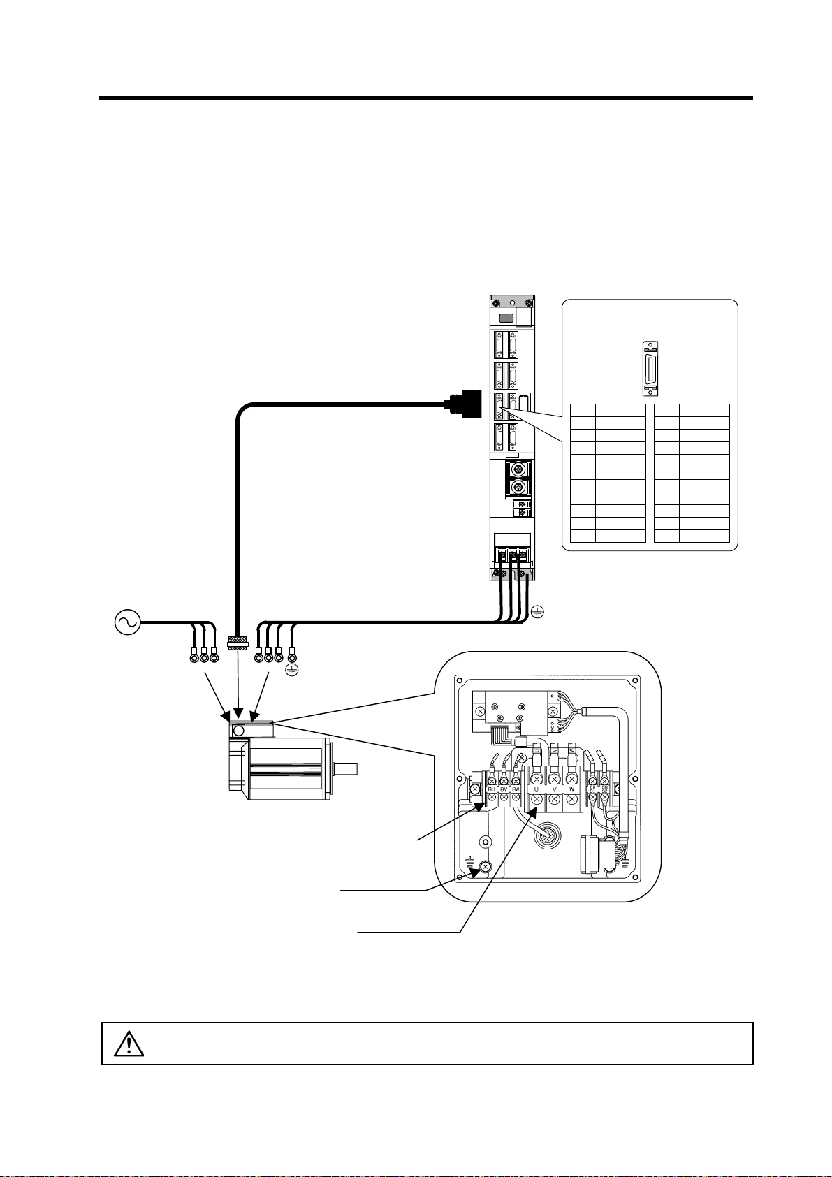
2. Wiring and Connection
2-4-4 Connection of the spindle motor
Refer to each motor specifications for details on the motor side connection destination, specifications
and outline, and for the spindle PLG detector specifications.
(1) Connecting the motor built-in PLG
MDS-C1-SP
Detector connector : CN5
Pin No.
BU
BV
BW
Max. 30m
U V W
Option cable : CNP5
Power cable
CN5
U VW
Pin
1
2
3
4
5
6
7
8
9
10
No.1
No.10
Name
LG
MOH
P15(+15V)
PA
PB
PZ
No.11
No.20
Pin
11
12
13
14
15
16
17
18
19
20
Name
RG
N15(-15V)
RA
RB
Spindle motor
Cooling fan terminal
block (BU,BV,BW)
Grounding terminal
Motor power terminal
block (U,V,W )
(Note) Either a single-phase or 3-phase power supply is used for the cooling fan.
Refer to the Spindle Motor Specifications for details.
CAUTION
The shield of spindle detector cable is not FG. Do not ground.
2 - 28
Example for 3-phase cooling fan
power supply
Page 68

(2) Connecting the magnetic sensor
Refer to section (1) for connection with the spindle motor.
2. Wiring and Connection
MDS-C1-SP
Detector connector : CN6
Pin No.
Max. 30m
U V W
Option cable : CNP5
Power cable
CN5
U VW
CN6
Pin
1
2
3
4
5
6
7
8
9
10
No.1
No.10
Name
P15(+15V)
MAG
LS
No.20
Pin
11
12
13
14
15
16
17
18
19
20
No.11
Name
LG
MAGR
LSR
Spindle motor
Magnetic sensor
Spindle
Option cable : CNP6M
CAUTION
The shield of spindle detector cable is not FG. Do not ground.
2 - 29
Page 69

2. Wiring and Connection
(3) Connecting the spindle end detector
Refer to section (1) for connection with the spindle motor.
MDS-C1-SP
Detector connector : CN6
Pin No.
Max. 30m
U V W
Option cable : CNP5
Power cable
CN5
U VW
CN6
Pin
1
2
3
4
5
6
7
8
9
10
No.1
No.10
Name
LG
MA
MB
MZ
P5(+5V)
No.20
Pin
11
12
13
14
15
16
17
18
19
20
No.11
Name
LG
MA*
MB*
MZ*
LG
P5(+5V)
P5(+5V)
Spindle motor
Spindle
Spindle end detector
Option cable: CNP6A
CAUTION
The shield of spindle detector cable is not FG. Do not ground.
2 - 30
Page 70

(4) Connecting the for C-axis detector
Refer to section (1) for connection with the spindle motor.
2. Wiring and Connection
MDS-C1-SP
Detector connector : CN6
Pin No.
Max. 30m
U V W
Spindle motor
Option cable : CNP5
Option cable : CNP7A
Power cable
CN5
CN7
U VW
CN6
Pin
1
2
3
4
5
6
7
8
9
10
No.1
No.10
Name
MA
MB
MZ
No.11
No.20
Pin
11
12
13
14
15
16
17
18
19
20
Detector connector : CN7
Pin No.
Pin
1
2
3
4
5
6
7
8
9
10
No.1
No.10
Name
LG
CA
CB
CZ
P5(+5V)
No.11
No.20
Pin
11
12
13
14
15
16
17
18
19
20
Name
MA*
MB*
MZ*
Name
LG
CA*
CB*
CZ*
LG
P5(+5V)
P5(+5V)
Spindle
C-axis detector
Option cable : CNP67A
Supplement
1. The C-axis control function is connected to the CN7 connector.
2. When using both the C-axis control function and orientation function, two cables (two-wire cable) are
connected from the detector.
3. The orientation signal connected to CN5 or CN6 can be connected to the NC with the differential
output from the CN8 connector.
CAUTION
The shield of spindle detector cable is not FG. Do not ground.
2 - 31
Page 71

2. Wiring and Connection
(5) Connecting the simple C-axis control
Refer to section (1) for connection with the spindle motor.
MDS-C1-SPX
MDS-C1-SPHX
Detector connector : CN7
Pin No.
U V W
Max. 30m
Option cable : CNP5
Power cable
CN5
CN7
U
VW
CN5
SH21
MDS-B-PJEX
Pin
1
2
3
4
5
6
7
8
9
10
No.1
No.10
Name
LG
CA
CB
CZ
P5(+5V)
No.11
No.20
Pin
11
12
13
14
15
16
17
18
19
20
Name
LG
CA*
CB*
CZ*
LG
P5(+5V)
P5(+5V)
Bottom
CN8
CR30
24VDC
power
Spindle motor
Z
A
B
G
Spindle end PLG
Motor axis
Spindle
VR1
VR2
VR4
CNP5
CAUTION
The shield of spindle detector cable is not FG. Do not ground.
2 - 32
Page 72

2. Wiring and Connection
2-5 Connection of power supply
1. Make sure that the power supply voltage is within the specified range of each
unit. Failure to observe this could lead to damage or faults.
2. For safety purposes, always install a No-fuse breaker (NFB), and make sure
that the circuit is cut off when an error occurs or during inspections.
3. The wire size will differ according to each drive unit capacity.
CAUTION
4. For safety purposes, always install a magnetic contactor (contactor) on the
main circuit power supply input. Large rush currents will flow when the power
is turned ON.
5. A semiconductor element is used in the power supply unit's magnetic contact
drive circuit, and a surge absorber is installed to protect the element.
Therefore, a leakage current of approx. 15mA is passed. Confirm that the
exciting coil in the magnetic contact will not function at 15mA or less.
2 - 33
Page 73

2. Wiring and Connection
2-5-1 Power supply input connection
(1) When using one power supply unit
Install the drive unit so that the DC power supply bus (L+, L-) is as near to the power supply unit as
possible. Large-capacity spindle drive units, in particular, should be installed adjacent to the power
supply unit which they control.
MDS-C1-CV
MDS-C1-SP
MDS-C1-V1/V2
No-fuse
breaker
R
S
T
: Main circuit
: Control circuit
AC
reactor
Ground
Breaker
Contactor
MC
CN4
L1
L2
L3
MC1
L11
L21
TE1
TE3
TE2
L+
L-
Ground
L+
L-
L11
L21
CN4
TE2
TE3
Ground
L+
L-
L11
L21
TE2
TE3
Ground
1. The power supply unit is a power supply regenerative type converter; an AC
reactor is surely installed in the power supply line.
2. When connecting to the TE3 terminal, connect to the power supply side
(primary side) of the AC reactor.
3. Connect the power supply unit's CN4 connector with the spindle drive unit of
CAUTION
the maximum capacity. If there is no spindle drive unit, connect to the servo
drive unit which is the unbalance axis.
4. When installing the units dispersed install the spindle drive unit adjacent to
the power supply unit, and connections for other drive units should be such
that the total TE2 wiring length is 50cm or less.
2 - 34
Page 74

r
r
2. Wiring and Connection
(2) When using two or more power supply units within a single NC communication bus system
Install a no-fuse breaker and a contactor for each of the power supply units.
MDS-C1-SPMDS-C1-CV
MDS-C1-V1/V2
R
S
T
No-fuse
breake
CN1A
CN1B
CN4
AC
Contactor
reactor
Ground
Breaker
MC
L1
L2
L3
MC1
L11
L21
TE1
TE3
TE2
L+
L-
Ground
L+
L-
L11
L21
CN4
MDS-C1-SPMDS-C1-CV
TE2
TE3
L+
L-
L11
L21
Ground
MDS-C1-V1/V2
CN1A
CN1A
CN1B
TE2
TE3
Ground
CN1A
To NC
R
S
T
No-fuse
breake
: Main circuit
: Control circuit
Ground
Breaker
CAUTION
AC
reactor
CN1B
Contactor
MC
CN4
L1
L2
L3
MC1
L11
L21
TE1
TE3
TE2
L+
L-
Ground
L+
L-
L11
L21
CN4
TE2
TE3
Ground
L+
L-
L11
L21
TE2
TE3
Ground
1. An AC reactor and breaker are required for each power supply unit.
2. When installing the units dispersed install the spindle drive unit adjacent to
the power supply unit, and connections for other drive units should be such
that the total TE2 wiring length is 50cm or less.
2 - 35
Page 75

r
2. Wiring and Connection
(3) When using one power supply shared by two NC communication bus systems
The axis connected to the power supply unit's CN4 connector becomes the power supply unit
control axis.
MDS-C1-SPMDS-C1-CV
MDS-C1-V1/V2
R
S
T
No-fuse
breake
CN4
CN9
AC
Contactor
reactor
Ground
Breaker
MC
L1
L2
L3
MC1
L11
L21
TE1
TE3
TE2
L+
L-
Ground
CN4
TE2
L+
L-
TE3
L11
L21
Ground
MDS-C1-V1/V2
CN4
L+
TE2
L-
L11
TE3
L21
Ground
MDS-C1-V1/V2
TE2
L+
L-
L11
L21
TE3
Ground
L+
L-
L11
L21
TE2
TE3
Ground
1. If the two NC communication bus systems include a spindle drive unit,
connect the power supply unit's CN4 connector to the CN4 connector of the
largest-capacity spindle drive unit. If there is no spindle drive unit, connect to
CAUTION
the unbalance-axis servo drive unit.
2. Install the spindle drive unit adjacent to the power supply unit, and
connections for other drive units should be such that the total TE2 wiring
length is 50cm or less.
2 - 36
Page 76

2. Wiring and Connection
2-5-2 Connecting the grounding cable
(1) Connecting the protective grounding (PE) and frame ground (FG)
Each unit has a terminal or mounting hole to connect PE (
Please connect an earth wire to the main ground of a cabinet or a machine frame at one point.
Ground each device according to the grounding conditions set forth by each country. (Typically, a
Y-connection neutral point ground is used in Europe.)
PE: Grounding to provide protection from electric shock, etc.
FG: Grounding to stabilize the operation of the devices, etc. (Suppress noise)
MDS-C1-V1/V2/SP
MDS-C1-CV
) or FG.
B-AL
Do not connect the grounding cable from
POINT
each unit directly to the grounding plate.
Noise from other units could result in
malfunctions.
(2) Grounding cable size
Earth wire size should follow the following table.
Type Grounding cable size (Required grounding)
MDS-C1-CV Unit Larger than thickness of wire connected to TE1 (L1/L2/L3). (PE)
MDS-C1-V1/V2/SP[] Unit Larger than thickness of wire connected to TE1 (U/V/W). (PE)
B-AL (AC Reactor) 5.5 mm2 (AWG10) or more (FG)
HC Series motor
SJ Series motor
Grounding plate
Unit
Unit
Grounding
Grounding
plate
plate
2 - 37
Page 77

(
)
p
2-5-3 Main circuit control
(1) Contactor ON sequence
Main circuit power is turned ON in the sequence shown below when an emergency stop status is
canceled.
Emergency stop (EMG)
Contactor control output (MC1)
PN bus voltage
Dynamic brake
Motor ON (GATE)
Motor brake control output (CN20)
Ready ON signal (READY)
Servo ON signal (SERVO)
(2) Contactor shutoff sequence
When an emergency stop occurs, the NC checks the MC shutoff permission (motor stop or dynamic
brake operation) status for all axes and then shuts off the contactors. If there is no MC shutoff
permission output, the contactors are forced off 30 seconds later by their control units. Contactors
are shut off immediately if an alarm occurs.
Emergency stop (EMG)
Servo 1st axis
(Dynamic brake stop)
Servo 2nd axis
(Deceleration control)
Servo 3rd axis
(Drop prevention control)
Spindle
(Deceleration stop)
Contactor control output (MC1)
OFF
ON
ON
OFF
OFF
ON
ON
OFF
OFF
ON
ON
OFF
ON
OFF
OFF
ON
Speed
MC shutoff
permission
Speed
MC shutoff
permission
Speed
MC shutoff
ermission
Speed
MC shutoff
permission
2. Wiring and Connection
0
Contactor ON sequence
0
0
Drop prevention
0
0
ON
OFF
500 1000 1500
PN charging completed
Ready completion
Command input enable
Shutoff after all-axes
permission check
Time
ms
Contactor shutoff sequence
2 - 38
Page 78

2. Wiring and Connection
2-6 Wiring of the motor brake
2-6-1 Wiring of the motor magnetic brake
The magnetic brake of servomotors with a magnetic brake is controlled by the motor brake control
connector (CN20) on the servo drive unit. The servo drive unit releases the brake when the motor is ON.
(Servo ON means when torque is generated in the motor.)
(1) Motor brake release sequence
The motor brake control output (CN20: MBR) releases the magnetic brake in the sequences in the
following drawing when canceling the emergency stop. The brake is released after the start of the
power ON to the servomotor.
Emergency stop (EMG)
Dynamic brake
ON
Cancel
Cancel
ON
Motor brake control
output (MBR)
Servo ready signal (RDY)
Servo ready completion
signal (SA)
Motor brake control sequences when an emergency stop is canceled
Cancel
ON
ON
OFF
ON
OFF
(2) Control during the servo OFF command
When a servo OFF command is input by an NC sequence input, the motor brake turns ON
simultaneously when the motor ON is shut off. Note that the vertical axis drop prevention control is
not validated, so a drop due to the brake operation lag occurs. When the servo OFF is canceled, a
drop due to an uncontrolled state does not occur.
Servo OFF command
Dynamic brake
Motor ON (GATE)
SERVO ON
SERVO OFF
OFF
ON
ON
OFF
Ready completion
Command input enable
0
500 1000 1500
Time (ms)
200ms
Motor brake control output
CN20 connector (MBR)
Motor brake control sequences when a servo OFF command is output
OFF
ON
1. The vertical axis drop prevention control only is performed during an
emergency stop (including alarms and power failures). It is not performed
CAUTION
when a servo OFF command is input.
2. A servo OFF command is required at both axes in order to perform a motor
brake control output (MBR) at 2-axis drive unit.
2 - 39
Page 79

A
y
2. Wiring and Connection
(3) Operation sequences when an emergency stop occurs
The motor brake control output operation when an emergency stop occurs differs according to the
motor deceleration stop method. Refer to section "4-5 Setting for emergency stop" for details on the
operation sequences for each stop method.
(4) Motor brake control connector (CN20) output circuit
As shown in the illustration below, an external power supply circuit is controlled by the CN20
connector output. Dynamic brake unit is controlled simultaneously for large-capacity drive unit
(MDS-C1-V1-110/150). Refer to "2-6-2 Dynamic brake unit wiring" for details.
MDS-C1-V1/V2
CN20
3 MBR2
DBR
2
1 MBR1
Emergenc
stop switch
lways install a surge
absorber
24VDC
Surge
absorber
(Unit internal relay specification: 5A 30Vdc/8A 250Vac)
Brake
1. Always install a surge absorber near the motor's brake terminal to eliminate
noise and protect the contacts.
CAUTION
2. The brakes cannot be released just by connecting the CN20 and motor brake
terminal. 24VDC must be supplied.
To ensure safety in an emergency, make sure that the magnetic brakes are
POINT
applied in sequence with the emergency stop switch.
2 - 40
Page 80

2. Wiring and Connection
2-6-2 Dynamic brake unit wiring
The 11kW and larger servo drive unit does not have built-in dynamic brakes. Always install a dynamic
brake unit.
The 9kW and smaller servo drive unit has built-in dynamic brakes.
Brake connector
(CN20)
Name
Pin
24VDC
1
DBU
2
3
MBR
MDS-C1-V1-110/150
CNU20S(AWG14)
1
2
3
Twist wire
Motor with a brake
External
power supply
24VDC GND
Control terminal
(M3)
block
Pin
Name
1
2
3
5 6 13
NC
a
b 4
14
U V W
a b
Dynamic brake unit
(MDS-B-DBU-150)
Servomotor
Drive terminal
(M3)
block
Name
Pin
1
U
V
2
3
W
Correct wire the dynamic brake unit to the servo drive unit.
CAUTION
Do not use for applications other than emergencies (normal braking, etc.). The
internal resistor could heat up, and lead to fires or faults.
When you use a servomotor with a brake, please wire (between 1pin and 3pin)
POINT
of CN20 connector.
2 - 41
Page 81

2. Wiring and Connection
2-7 Peripheral control wiring
2-7-1 Input/output circuit wiring
The input/output circuit to control the external signal such as external emergency stop input and relay
changeover signal output is wired.
The input/output circuit for each unit is as follows.
Input circuit Output circuit
Switch
24V
Input condition
Switch ON
Switch OFF
For a switch or relay to be wired, use a switch or relay that satisfies the input/output (voltage, current)
conditions.
For digital input signal (CN23,CN9)
For digital output signal (CN9)
CN9 connector
24V
10k
33.3k
MPI1
24G
CN23 connector
Switch
20
10
3
1
Servo/spindle
drive unit
2k
Power supply unit
18VDC to 25.2VDC
9mA or more
4VDC or less
2mA or less
Interface name Selection example
Use a minute signal switch which is stably contacted and operated even with low
voltage or current
<Example> OMRON: G2A, G6B type, MY type, LY type
Use a compact relay operated with rating of 24VDC, 50mA or less.
<Example> OMROM: G6B type, MY type
24V
Servo/spindle
The part indicated by the " " must be prepared
by the user.
Output condition
Output voltage 24VDC ±5%
Tolerable output
current Io
CN9 connector
drive unit
18
10
MPO1
8
MPO2
24G
Relay, etc.
50mA or less
2 - 42
Page 82

2. Wiring and Connection
2-7-2 Spindle coil changeover
There are spindle motors capable of coil changeover control, which enables favorable characteristics to
be attained from low speeds to high speeds by changing two types or three types (only for
MDS-C1-SPM) of coils.
(1) Coil changeover control
The speed at which to change the coils is detected by the spindle drive according to the value set
with spindle parameter SP020. This is conveyed to the NC with a speed detection (SD) signal. The
NC judges the other conditions (coil fixed, etc.), and issue a coil changeover command to the
spindle drive with the L coil selection command (LCS).
To prevent the contactor from varying, the hysteresis set with SP047 is applied on the speed when
changing from the low-speed coil to the high-speed coil and the high-speed coil to the low-speed
coil.
6000
Spindle motor speed
(r/min)
Speed detection (SD1) [SP→NC]
L coil selection command (LCS) [NC→SP]
Changing coil (MKC) [SP→NC]
Contactor changeover
Spindle motor coil changeover control
4000
2000
0
Low-speed coil
(SP020+SP047
High-speed coil
No. Abbrev. Parameter name Description Setting range
SP020 SDTS* Speed detection
set value
SP047 SDTR* Speed detection
reset value
Set the motor speed of which speed detection 1 output is
performed. Usually, the setting value is 10% of SP017 (TSP).
Set the reset hysteresis width for a speed detection set value
defined in SP020 (SDTS).
0 to 32767
Low-speed coil
(r/min)
0 to 1000
(r/min)
SP020
Time
Standard
value
600
30
2 - 43
Page 83

2. Wiring and Connection
(2) Protective functions
[1] Base shutoff after a winding changeover
When the L-coil selection command (LCS) is used to perform low-speed winding → high-speed
winding switching, or vice-versa, the base is shut off during contactor operation time in order to
protect the spindle drive unit's main circuit. The base shutoff time is determined by the "Winding
changeover base shutoff timer" (SP059) setting. The standard time setting should be used, as a
shorter time can cause contactor burn damage.
(Refer to 5-2-2 (4) "Spindle control output 4" Coil changing (bit 6) for details.)
No. Abbrev. Parameter name Description Setting range
SP059 MKT* Winding
changeover base
shut-off timer
Set the base shut-off time for contactor switching at coil
changeover.
Note that the contactor may be damaged with burning if the
value of this parameter is too small.
50 to 10000
[2] Current limit after coil changeover
Following a coil changeover, the current is limited (SP061) for the period specified by the current
limit timer (SV060) in order to stabilize control. Because position loop control (synchronous tap,
C-axis control, etc.) that occurs immediately after a coil changeover will result in unstable control,
be sure that position commands specified by the sequence is input after the current limit is
cancelled.
No. Abbrev. Parameter name Description Setting range
SP060 MKT2* Current limit timer
after coil
changeover
SP061 MKIL* Current limit value
after coil
changeover
Set the current limit time to be taken after completion of
contactor switching at coil changeover.
Set the current limit value during a period defined in SP060
(MKT2) after completion of contactor switching at coil
changeover.
0 to 10000
0 to 120 (%) 75
(ms)
(ms)
Standard
value
150
Standard
value
500
2 - 44
Page 84

p
(3) Wiring
The illustration below shows the 2 types of changeover that occur after a coil changeover, (a) Y
(star) – ∆ (delta) changeover, and (b) Y (star) – Y (star) changeover. As shown in (c), one of the
contactors (MC1 or MC2) is turned ON and the other is turned OFF at all of the coil changeover
control circuits.
U
V
W
Spindle drive unit
terminal block
2. Wiring and Connection
U
V
W
MC2
MC1
MC1: Contactor to connect low-speed coil (Y-connection)
MC2: Contactor to connect high-speed coil (∆-connection)
X
Y
Z
indle motor
S
(a) Y (star) - ∆ (delta) changeover circuit
U
V
W
Spindle drive unit
terminal block
MC1: Contactor to connect low-speed coil (1st Y-connection)
MC2: Contactor to connect high-speed coil (2nd Y-connection)
MC1
MC2
U1
V1
W1
U2
V2
W2
Spindle motor
(b) Y (star) - Y (star) changeover circuit
MDS-C1-SP
RA
RA
CN9-8
CN9-10
RA
MC2
S
MC1 SK
T
MC1
MC2 SK
(c) Coil changeover control circuit (common)
Coil changeover relay control circuit
2 - 45
Page 85

C
L
L
2. Wiring and Connection
2-7-3 Wiring of an external emergency stop
(1) External emergency stop setting
Besides the emergency stop input from the NC communication cable (CN1A, CN1B),
double-protection when an emergency stop occurs can be provided by directly inputting an external
emergency stop to the CN23 connector on the power supply unit. Even if the emergency stop is not
input from CNC for some reason, the contactors will be shut off by the external emergency stop
input from CN23 connector on the power supply unit.
[1] Connection
Mitsubishi NC
SV1,2
[2] Setting
When using the external emergency stop, the rotary switch on the front of the power supply unit and
the parameter (PTYP) of drive unit that controls the power supply must be set.
• Rotary switch setting: 4
• Parameter setting: Add "0040" to the setting of PTYP (Servo=SV036, Spindle=SP041).
Parameter settings
Abbrevia-
No.
SV036
SP041
tion
PTYP Power supply type
Emergency
stop
Alarm
SH21
FCUA-R000
External emergency stop input
Parameter name Descriptions
MDS-C1-V1/V2/SP
CN1A
When external emergency stop is validated, 0040 [hex] is added to PTYP for the drive
unit connected to the power supply unit.
CN1B
CN4
Emergency
stop
Alarm
SH21
FCUA-R000
MDS-C1-CV
CN4
CN23
1 EMG1
2
N
3 EMG2
MC1
MC1
11
21
Contactor shutoff
command
CAUTION
for the external emergency stop function (CN23).
2 - 46
The emergency stop signal input to the CNC side cannot be used as a substitute
Page 86

2. Wiring and Connection
(2) Operation sequences of CN23 external emergency stop function
If only external emergency stop is input when external emergency stop valid is set in the
parameters (the emergency stop is not input in NC), an "In external emergency stop" (warning EA)
will be detected. At this time, the system itself does not enter an emergency stop status. (There will
be no deceleration control or dynamic brake stop.)
If a contactor shutoff command is not issued from the NC within 30 seconds after the external
emergency stop is input, the power supply unit outputs contactor shutoff signal (MC1), and then it
shuts off the contactors, and a power supply error (alarm 6F) is detected simultaneously. If the
emergency stop is input from NC within 30 seconds, the warning EA replaces the "In NC
emergency stop" (warning E7). A normal emergency stop status will result if the contactor shutoff
command from the NC are further input.
Ready ON is possible even if CN23, an external emergency stop has been input when the
emergency stop is canceled, but an power supply error (alarm 6F) will occur after 30 seconds.
External emergency stop input
(EMGX)
Main emergency stop input
(EMG)
Motor speed
Contactor control command
Contactor control terminal (MC)
OFF
ON
OFF
ON
Deceleration control
0
ON
OFF
ON
OFF
Servo drive unit status display
External emergency stop input
(EMGX)
Main emergency stop input
(EMG)
Motor speed
Contactor control command
Contactor control terminal (MC)
Servo drive unit status display
When neither a main emergency stop nor contactor shutoff command is input
dx E7 EA
External emergency stop input sequences
OFF
ON
OFF
ON
0
ON
OFF
ON
OFF
dx 6F, E7 EA
0 30
Cx → dx
The communication line enters an
emergency stop state by the output
from the servo.
Dynamic brake
Tim e (s)
2 - 47
Page 87

(3) Example of emergency stop circuit
[1] Outline of function
The power supply unit's external emergency stop can be validated by wiring to the CN23 connector,
and setting the parameters and rotary switch. If the emergency stop cannot be processed and the
external contractor cannot be shut off (due to a fault) by the NC unit, the external contactor can be
shut off by the power supply unit instead of the NC. At this time, the spindle motor will coast and the
servomotor will stop with the dynamic brakes.
EN60204-1 Category 1 can be basically complied with by inputting the external emergency stop
and installing contactor.
1. The power supply unit external emergency stop function is a function that
assists the NC emergency stop.
CAUTION
2. It will take 30 seconds for the external contactor to function after the
emergency stop is input to CN23. (This time is fixed.)
[2] Outline of function
The emergency stop is a signal used to
stop the machine in an emergency. This
is connected to the NC unit. Wire to the
power supply unit when necessary.
The servo/spindle unit will be decelerated
and controlled by the software according
to the emergency stop command issued
from the NC unit. (The deceleration
control depends on a parameter setting.)
The diagram on the right shows an
example of the emergency stop circuit
(EN60204-1 Category 0 stop) in which an
off delay timer (TM1) is installed as a
power shutoff method independent from
the NC emergency stop input. The
required safety category may be high depending on the machine and the Safety Standards may not
be met. Thus, always pay special attention when selecting the parts and designing the circuit.
[3] Setting the off delay timer (TM1) time
Set the TM1 operation time so that it functions after it has been confirmed that all axes have
stopped. If the set time is too short, the spindle motor will coast to a stop.
Provide a mechanism that shuts off the power even if the NC system fails.
2. Wiring and Connection
TM1
External
Emergency
Switch
R
tm ≥ All axes stop time
MC
External
Contactor
RA1
MBR*
AC Reactor
R
GND
GND
CN23
EMG
Power Supply
Unit
CUP
&
ASIC
L11
L21
MC-OFF*
MC1
L1
L2
L3
NC Unit
CN4
CUP
&
ASIC
Servo/Spindle
Drive Unit
CN4
L11
L21
P
N
SV1/2
CUP
&
ASIC
Hardware Emergency
CN1A/B
Software Emergency
CN20
MBR*
Motor
Brake
Stop Categories in EN60204-1
Category 0: The power is instantly shut off using machine parts.
Category 1: The drive section is stopped with the control (hardware/software
or communication network), and then the power is instantly shut
POINT
off using machine parts.
(Caution) Refer to the Standards for details.
Refer to Section 9.2.5.4.2 in EN60204-1: Safety of Machinery
Electrical Equipment of Machines – Part 1.
2 - 48
Page 88

3. Setup
3-1 Initial setup........................................................................................................................................ 3-2
3-1-1 Setting the rotary switch ............................................................................................................ 3-2
3-1-2 Transition of LED display after power is turned ON .................................................................. 3-3
3-1-3 Servo standard specifications and high-gain specifications ...................................................... 3-4
3-2 Setting the initial parameters for the servo drive unit (High-gain specifications).......................... 3-5
3-2-1 Setting the standard parameters ............................................................................................... 3-5
3-2-2 List of standard parameters for each servomotor.................................................................... 3-11
3-2-3 Servo parameter list................................................................................................................. 3-23
3-3 Setting the initial parameters for the servo drive unit (Standard specifications) ............................ 3-39
3-3-1 Setting the standard parameters ............................................................................................. 3-39
3-3-2 List of standard parameters for each servomotor.................................................................... 3-44
3-3-3 Servo parameter list................................................................................................................. 3-51
3-4 Restrictions on servo control .......................................................................................................... 3-63
3-4-1 Restrictions of electronic gear setting value ............................................................................3-63
3-4-2 Restrictions on absolute position control ................................................................................. 3-64
3-5 Setting the initial parameters for the spindle drive unit................................................................... 3-65
3-5-1 Spindle specification parameters............................................................................................. 3-65
3-5-2 List of spindle parameters........................................................................................................ 3-70
3-6 Initial adjustment of the spindle PLG............................................................................................ 3-104
3-6-1 Adjusting the PLG installation................................................................................................ 3-104
3-6-2 Z phase automatic adjustment............................................................................................... 3-110
3-6-3 Motor end PLG automatic adjustment ................................................................................... 3-111
3-6-4 Spindle end PLG automatic adjustment ................................................................................ 3-112
3 - 1
Page 89

3. Setup
3-1 Initial setup
3-1-1 Setting the rotary switch
Before turning on the power, the axis No. must be set with the rotary switch. The rotary switch settings
will be validated when the units are turned ON.
1st axis
Servo drive unit
(MDS-C1-V1)
Setting the
rotary switch
2nd axis
Servo drive unit
Spindle drive unit
(MDS-C1-SP)
Power supply unit
(MDS-C1-CV)
(MDS-C1-V2)
5 B
4 C
3 D
8
7 9
6 A
2 E
1 F
0
L axis
7 9
6 A
5 B
4 C
3 D
2 E
1 F
M axis
8
8
7 9
6 A
5 B
4 C
3 D
2 E
1 F
0
0
4 C
8
7 9
6 A
5 B
3 D
2 E
1 F
0
Details
Setting the MDS-C1-V1/V2/SP Setting the MDS-C1-CV
0 1st axis External emergency stop invalid
1 2nd axis
2 3rd axis
Setting prohibited
3 4th axis
4 5th axis
External emergency stop valid
(Used CN23)
5 6th axis
6 7th axis
7
8
9
A
B
Setting prohibited
Setting prohibited
C
D
E
F Axis not used
8
7 9
6 A
5 B
4 C
3 D
2 E
1 F
0
When an axis that is not used is selected, that axis will not be controlled when
the power is turned ON, and "Ab" will remain displayed on the LED. If the power
POINT
of the axis not in use is disconnected, the NC system's emergency stop cannot
be released.
3 - 2
Page 90

3. Setup
3-1-2 Transition of LED display after power is turned ON
When CNC, each drive unit and the power supply unit power have been turned ON, each unit will
automatically execute self-diagnosis and initial settings for operation, etc. The LEDs on the front of the
units will change as shown below according to the progression of these processes.
If an alarm occurs, the alarm No. will appear on the LEDs. Refer to "6-1 LED display when alarm or
warning occurs" for details on the alarm displays.
Waiting for NC
power start up
NC power ON
Servo ON state Servo OFF sate
NC power OFF
Drive units
LED display
NC power ON
Drive unit initialization complete
Waiting for NC power start up
Executing initial
communication with NC
Emergency stop state
The LED will alternate between
F# → E7 → not lit.
(# is the set axis No.)
Repeats lighting and going out.
(1st axis in the display example)
Power supply unit
LED display
NC power
ON
Executing initial communication
with NC
A : Initializing
b : Ready OFF, in emergency stop
c : Ready ON/servo OFF
Servo ON state
Emergency stop state
CAUTION
Always input emergency stop when starting the servo system.
3 - 3
Page 91

3. Setup
3-1-3 Servo standard specifications and high-gain specifications
(1) Two-part system compliance
With the MDS-C1-V1/V2 Series, control is possible with the standard servo (MDS-B-V1/V2) control
mode and high-gain servo (MDS-B-V14/V24) control mode. When replacing an older model
(MDS-B Series) with this series, the servo parameter settings are automatically recognized and the
control mode is determined. Thus, the model can be changed from either a standard servo or
high-gain servo without changing the servo parameters.
When using the MDS-C1-V1/V2 unit and newly adjusting the machine, select the high-gain
specifications. The high-gain specifications are set as the default.
(2) Judging the control mode
Whether the servo drive unit starts up with the standard servo specifications or high-gain servo
specifications depends on the servo parameter SV009 to SV012 and SV033/bit8, 9 settings.
Parameter High-gain Standard Standard High-gain High-gain
SV009
SV010
SV011
SV012
SV033/bit8 0 0 1 0 1
SV033/bit9 0 0 0 1 1
(Note) * indicates that there are no limits.
SV009 = 4096 or more, and
SV010 = 4096 or more, and
SV011 = 768 or more, and
SV012 = 768 or more
(3) Servo monitor unit type display
Whether the system is running with the high-gain servo or standard servo control mode can be
confirmed with the unit type displayed on the NC SERVO MONITOR screen.
Unit type For standard servo specifications For high-gain servo specifications
MDS-C1-V1- C1V1s C1V1-
MDS-C1-V2-{{ C1V2s{{ C1V2-{{
MDS-C1-V1-45S C1V1s4S C1V1-4S
MDS-C1-V1-70S C1V1s7S C1V1-7S
MDS-C1-V2-3510S C1V2s3510 C1V2-3510
MDS-C1-V2-3520S C1V2s3520 C1V2-3520
MDS-C1-V2-4545S C1V2s4S4S C1V2-4S4S
MDS-C1-V2-7070S C1V2s7S7S C1V2-7S7S
MDS-C1-V2-9090S C1V2s9S9S C1V2-9S9S
Setting that does not satisfy even
one of the following conditions:
SV009 = 4096 or more
SV010 = 4096 or more
SV011 = 768 or more
SV012 = 768 or more
SV009=*
SV010=*
SV011=*
SV012=*
SV009=*
SV010=*
SV011=*
SV012=*
SV009=*
SV010=*
SV011=*
SV012=*
1. To change the control mode to the high-gain servo specifications after
replacing the unit from a standard servo (MDS-B-V1/V2), the parameters
CAUTION
must be changed and adjusted for high-gain servo use.
2. If alarm 7F occurs after setting the servo parameters, turn the servo drive
unit power ON again.
3 - 4
Page 92

3. Setup
3-2 Setting the initial parameters for the servo drive unit (High-gain specifications)
The servo parameters must be set before the servo system can be started up. The servo parameters
are input from the NC. The input method differs according to the NC being used, so refer to each NC
Instruction Manual.
3-2-1 Setting the standard parameters
When starting up the system, first set the standard parameters listed in "3-2-2 List of standard
parameters for each servomotor". For the parameters shown below, check the machine and servo
system specifications and determine the setting value.
(1) Basic specification parameters
[1] When performing absolute position control, set SV017/bit7=1. This may be automatically set by
NC system parameter setting, depending on NC model. (Setting on the servo parameter screen
is not valid.)
[2] When performing absolute position control with speed and current synchronous control, set
SV081/bit4=1 for master and slave axes. Also set SV017/bit7=1.
[3] For HA053N, HA13N, HA23N, HA33N motors, if the connector direction of the motor end
detector with motor power connector is 90°, set SV017/bit5=1. If the angle is 180°, use a
High-gain specifications
No. Abbrev.
SV017 SPEC*
SV081 SPEC2*
Parameters with an asterisk * in the abbreviation, such as PC1*, are validated with the NC power turned ON again.
standard setting (SV017/bit5=0).
Parameter
name
Servo
specification
selection 1
Servo
specification
selction 2
Setting of absolute position control (SV017/bit7) may be set automatically by NC
POINT
system parameter setting, depending on NC model. In this case, setting on the servo
parameter screen is not valid.
Setting basic specification parameters
Explanation
F E D C B A 9 8 7 6 5 4 3 2 1 0
spm mpt mp abs vdir fdir vfb seqh dfbx fdir2
bit Meaning when "0" is set Meaning when "1" is set
Standard setting HA motor (4 pole motor)
5 vdir
7 abs Incremental control Absolute position control
F E D C B A 9 8 7 6 5 4 3 2 1 0
pabs rabs
bit Meaning when "0" is set Meaning when "1" is set
4 pabs Normal setting
Detector installation position 90
degrees (B, D)
Speed/current synchronous
control absolute position control
3 - 5
Page 93

3. Setup
(2) Electronic gear related parameters
The setting range of the following parameters, which configure the electronic gears, may be limited
according to the combination. Refer to section "3-4 Restrictions on servo control" for details.
High-gain specifications
No. Abbrev. Parameter name Explanation
SV001 PC1*
SV002 PC2*
SV018 PIT*
Motor side gear
ratio
Machine side gear
ratio
Ball screw pitch Set the ball screw pitch. Set to "360" for the rotary axis.
Set the motor side and machine side gear ratio.
For the rotary axis, set the total deceleration (acceleration) ratio.
Even if the gear ratio is within the setting range, the electronic gears may
overflow and cause an alarm.
In the case of the semi-closed loop control
Set the same value as SV020 (RNG2). (Refer to the explanation of
SV020.)
In the case of the full-closed loop control
Set the number of pulses per ball screw pitch.
Detector model name Resolution SV019 setting
OHE25K-ET, OHA25K-ET 100,000 (p/rev) 100
OSE104-ET,OSA104-ET 100,000 (p/rev) 100
OSE105-ET,OSA105-ET 1,000,000 (p/rev) 1000
SV019 RNG1*
Position detector
resolution
Relative position detection
scale
AT41 (Mitsutoyo) 1 (µm/p)
FME type, FLE type
(Futaba)
MP type (Mitsubishi Heavy
Industries)
AT342 (Mitsutoyo) 0.5 (µm/p)
AT343 (Mitsutoyo) 0.05 (µm/p)
AT543 (Mitsutoyo)
LC191M (Heidenhain) 0.1, 0.05 (µm/p)
LC491M (Heidenhain) 0.05 (µm/p)
RCN223(Heidenhain) 8,000,000(p/rev) 8000
RCN723(Heidenhain) 8,000,000(p/rev) 8000
MDS-B-HR - PIT/scale(μm)
Refer to detector
specification manual
Refer to detector
specification manual
Refer to detector
specification manual
0.05 (µm/p)
PIT/Resolution
The same as
SV018 (PIT)
PIT/Resolution
PIT/Resolution
Twice as big as
SV018 (PIT)
20 times as big as
SV018 (PIT)
20 times as big as
SV018 (PIT)
PIT/Resolution
PIT/Resolution
µm)
(
µm)
(
µm)
(
µm)
(
µm)
(
Set the number of pulses per one revolution of the motor end detector.
SV020 RNG2*
Speed detector
resolution
Detector model name SV020 setting
OSE104, OSA104 100
OSE105, OSA105 1000
Parameters with an asterisk * in the abbreviation, such as PC1*, are validated with the NC power turned ON again.
range (Unit)
1 to 32767
1 to 32767
1 to 32767
(mm/rev)
1 to 9999
1 to 3000
1 to 9999
Setting
(kp/rev)
(kp/pit)
(kp/rev)
3 - 6
Page 94

(3) Detector related parameters
(a) For semi-closed loop control
For control using only the motor end detector, specify the settings shown in the table below. For
speed and current synchronous control, refer to section "2-4-3 Connecting the synchronous control
system".
High-gain specifications
No. Abbrev. Parameter name
SV025 MTYP*
Motor/Detector type
(b) For full-closed loop control
Some parameter settings must be specified in order to use the machine end detector. These
settings are determined by type or the installation conditions of the linear scale and the ball screw
end detector.
3. Setup
Setting for semi-closed loop control
Explanation
bit Details
8
9
A
B
C OSE104 0 0
D OSA104 1 1
E
F
Set the detector type.
Set the position detector type for "pen", and the speed detector type
ent
for "ent". In the case of the semi-closed loop control, set the same
value for "pen" and "ent".
Detector model name pen setting ent setting
pen
OSE105, OSA105 2 2
[1] The SV025/bit8 to B (ent) setting must be specified according to the motor end detector
specifications, in the same manner as for semi-closed loop control. For current synchronous
control, however, refer to section "2-4-3 Connecting the synchronous control system".
[2] If the polarities of the motor end detector and the machine end detector do not match, specify
SV017/bit4=1 setting.
[3] To use AT342, AT343, AT543, LC191M, LC491M, specify SV027/bit6=1 setting.
[4] To use the MP scale, specify SV017/bit8 setting in accordance with the scale specifications.
For absolute position control, specify SV017/bit9=1 setting.
[5] For ABZ phase pulse output type relative position detection scale with constant Z-phase
detection position without regard to the travel direction, specify SV027/bit6=1 setting. Z-phase
detection occurs as follows: Plus-direction travel: Rising edge detection, Minus-direction
travel: Falling edge detection
[6] For machine end absolute position control at the rotation axis, specify SV081/bit1=1 setting.
[7] For speed and current synchronous control, refer to "2-4-3 Connecting the synchronous
control system".
3 - 7
Page 95

3. Setup
Setting for full-closed loop control
High-gain specifications
No. Abbrev. Parameter name
Explanation
F E D C B A 9 8 7 6 5 4 3 2 1 0
spm mpt mp abs vdir fdir vfb seqh dfbx fdir2
SV017 SPEC*
Servo specification
selection
bit Meaning when "0" is set Meaning when "1" is set
4 fdir Position feedback forward polarity Position feedback reverse polarity
8 mp MP scale 360P (2mm pitch) MP scale 720P (1mm pitch)
9 mpt
MP scale ABS detection NC
control
MP scale ABS detection
automatic (Standard setting)
bit Explanation
Set the detector type.
Set the position detector type for “pen”, and the speed detector type
for “ent”. In the case of the semi-closed loop control, set the same
ent
value for “pen” and “ent”.
pen
setting
0 (Note)
1 (Note) 1
2 (Note) 2
3 (Note) 3
4
5
6
7
8
9
A
B
C
D
E
F
ent setting
impossible
impossible
impossible
impossible
impossible
impossible
impossible
impossible
synchronization)
synchronization)
impossible
impossible
pen
Detector model name
OSE104
OSA104
OSE105, OSA105
OHE25K-ET,OSE104-ET
OHA25K-ET,OSA104-ET
OSE105-ET, OSA105-ET, RCN223,
RCN723 (Heidenhain)
Relative position detection scale, MP
type (Mitsubishi Heavy Industries)
AT41 (Mitsutoyo), FME type, FLE type
(Futaba)
AT342, AT343, AT543 (Mitsutoyo),
LC191M/491M (Heidenhain), MDS-B-HR
The setting of the slave axis in the
speed/current synchronization control.
When the master axis is the semi-closed
control.
The setting of the slave axis in the speed/
current synchronization control.
When the master axis is the full-closed
control.
(Current synchronization control is only
for MDS-C1-V2.)
(Current
(Current
SV025 MTYP*
Motor/Detector type
8
9
A
B
C
D
E
F
(Note) Setting for semi-closed loop control
Parameters with an asterisk * in the abbreviation, such as PC1*, are validated with the NC power turned ON again.
0
Setting
Setting
Setting
Setting
Setting
Setting
Setting
Setting
C
E
Setting
Setting
3 - 8
Page 96

3. Setup
Setting for full-closed loop control
High-gain specifications
Abbr
No.
SV027 SSF1
SV081 SPEC2*
Parameters with an asterisk * in the abbreviation, such as PC1*, are validated with the NC power turned ON again.
ev.
Parameter name
Servo function
selection 1
Servo function
selection 2
F E D C B A 9 8 7 6 5 4 3 2 1 0
aflt zrn2 afse ovs lmc omr zrn3 vfct upc vcnt
bit
6 zrn3
F E D C B A 9 8 7 6 5 4 3 2 1 0
pabs rabs
bit Meaning when "0" is set Meaning when "1" is set
1 rabs
Meaning when "0" is set Meaning when "1" is set
ABZ phase scale: Set to "1" to fix Z-phase detection edge.
Absolute position scale: Set to "1" in using AT342/343,
LC191M/491M.
Normal setting Rotary axis machine end absolute
Explanation
position control
3 - 9
Page 97

p
p
3. Setup
(4) Setting the power supply type
Set the drive unit connected to the power supply unit with the CN4 connector. This does not need
to be set if the power supply for the axis is not connected with the CN4 connector. (Set "0000".)
If the power supply unit is connected with the spindle drive unit, the parameters do not need to be
set on the servo side. When connected to a 2-axis servo drive unit (MDS-C1-V2), set the power
supply type for one of the two target axes.
High-gain specifications
No. Abbrev. Parameter name Explanation
F E D C B A 9 8 7 6 5 4 3 2 1 0
amp rtyp ptyp
bit Explanation
When the CN4 connector of the drive unit and the power supply unit
are connected, setting below is necessary.
ptyp
Set the regenerative resistor type when using MDS-A-CR.
Set 0 when using the MDS-C1-CV (power regeneration.)
rtyp
amp
Not
x0
used
x4 CV-37 CR-37
x5 CV-150
x6 CV-55 CV-260 CR-55
x7 CV-370
x8 CV-75 CR-75
x9 CV-185 CR-90
CV-300
SV036 PTYP*
0
1
2 To validate the external emergency stop function, add 40h.
3 Setting 0x 1x 2x 3x 4x 5x 6x 7x 8x
4
5 x1 CV-110 CR-10
6 x2 CV-220 CR-15
7 x3 CR-22
Power supply type
8
9
A
B
C Set "0".
D
E
F
MDS-B-
CVE-450
MDS-B-
CVE-550
Parameters with an asterisk * in the abbreviation, such as PC1*, are validated with the NC power turned ON again.
If alarm 7F occurs after setting the initial parameters, turn the drive unit power ON again. If the unit's
LEDs indicate the following emergency stop state, the unit has started up normally.
F1
F+axis No.
E7
Emergency
sto
F1
F+axis No.
E7
Emergency
sto
Not lit
Normal LED display when NC power is turned ON (1st axis)
3 - 10
Page 98

3. Setup
3-2-2 List of standard parameters for each servomotor
(1) HC Series (Standard 2000r/min rating)
High-gain specifications
Parameter
No. Abbrev. Details Unit capacity 05 10 20 20 35 45S 45 70S 70 90S 90
SV001 PC1 Motor side gear ratio --- --- --- --- --- --- --- --- --- --- --SV002 PC2 Machine side gear ratio --- --- --- --- --- --- --- --- --- --- --SV003 PGN1 Position loop gain 1 47 47 47 47 47 47 47 47 47 47 47
SV004 PGN2 Position loop gain 2 0 0 0 0 0 0 0 0 0 0 0
SV005 VGN1 Speed loop gain 1 200 200 200 200 200 200 200 200 200 200 200
SV006 VGN2 Speed loop gain 2 0 0 0 0 0 0 0 0 0 0 0
SV007 VIL Speed loop delay compensation 0 0 0 0 0 0 0 0 0 0 0
SV008 VIA Speed loop lead compensation 1364 1364 1364 1364 1364 1364 1364 1364 1364 1364 1364
SV009 IQA Current loop q axis lead compensation 4096 4096 4096 4096 4096 4096 4096 4096 4096 4096 4096
SV010 IDA Current loop d axis lead compensation 4096 4096 4096 4096 4096 4096 4096 4096 4096 4096 4096
SV011 IQG Current loop q axis gain 768 768 768 768 768 768 768 768 768 768 768
SV012 IDG Current loop d axis gain 768 768 768 768 768 768 768 768 768 768 768
SV013 ILMT Current limit value 500 500 500 500 500 500 500 500 500 500 500
SV014 ILMTsp Current limit value in special control 500 500 500 500 500 500 500 500 500 500 500
SV015 FFC Acceleration rate feed forward gain 0 0 0 0 0 0 0 0 0 0 0
SV016 LMC1 Lost motion compensation 1 0 0 0 0 0 0 0 0 0 0 0
SV017 SPEC Servo specification selection 0000 0000 0000 0000 0000 1000 0000 1000 0000 1000 0000
SV018 PIT Ball screw pitch --- --- --- --- --- --- --- --- --- --- --SV019 RNG1 Position detector resolution --- --- --- --- --- --- --- --- --- --- --SV020 RNG2 Speed detector resolution --- --- --- --- --- --- --- --- --- --- --SV021 OLT Overload detection time constant 60 60 60 60 60 60 60 60 60 60 60
SV022 OLL Overload detection level 150 150 150 150 150 150 150 150 150 150 150
SV023 OD1 Excessive error detection width during servo ON 6 6 6 6 6 6 6 6 6 6 6
SV024 INP In-position detection width 50 50 50 50 50 50 50 50 50 50 50
SV025 MTYP Motor/detector type xxB0 xxB1 xxB2 xxB3 xxB4 xx95 xxB5 xx96 xxB6 xx97 xxB7
SV026 OD2
SV027 SSF1 Servo function selection 1 4000 4000 4000 4000 4000 4000 4000 4000 4000 4000 4000
SV028 0 0 0 0 0 0 0 0 0 0 0
SV029 VCS Speed at the change of speed loop gain 0 0 0 0 0 0 0 0 0 0 0
SV030 IVC
SV031 OVS1 Overshooting compensation 1 0 0 0 0 0 0 0 0 0 0 0
SV032 TOF Torque offset 0 0 0 0 0 0 0 0 0 0 0
SV033 SSF2 Servo function selection 2 0000 0000 0000 0000 0000 0000 0000 0000 0000 0000 0000
SV034 SSF3 Servo function selection 3 0003 0003 0003 0003 0003 0003 0003 0003 0003 0003 0003
SV035 SSF4 Servo function selection 4 0000 0000 0040 0040 0040 0040 0040 0040 0040 0000 0000
SV036 PTYP Power supply type 0000 0000 0000 0000 0000 0000 0000 0000 0000 0000 0000
SV037 JL Load inertia scale 0 0 0 0 0 0 0 0 0 0 0
SV038 FHz1 Notch filter frequency 1 0 0 0 0 0 0 0 0 0 0 0
SV039 LMCD Lost motion compensation timing 0 0 0 0 0 0 0 0 0 0 0
SV040 LMCT
SV041 LMC2 Lost motion compensation 2 0 0 0 0 0 0 0 0 0 0 0
SV042 OVS2 Overshooting compensation 2 0 0 0 0 0 0 0 0 0 0 0
SV043 OBS1 Disturbance observer filter frequency 0 0 0 0 0 0 0 0 0 0 0
SV044 OBS2 Disturbance observer gain 0 0 0 0 0 0 0 0 0 0 0
SV045 TRUB Frictional torque/current bias 3 0 0 0 0 0 0 0 0 0 0 0
SV046 FHz2 Notch filter frequency 2 0 0 0 0 0 0 0 0 0 0 0
SV047 EC Inductive voltage compensation gain 100 100 100 100 100 100 100 100 100 100 100
SV048 EMGrt Vertical axis drop prevention time 0 0 0 0 0 0 0 0 0 0 0
SV049 PGN1sp
SV050 PGN2sp
SV051 DFBT Dual feedback control time constant 0 0 0 0 0 0 0 0 0 0 0
SV052 DFBN Dual feedback control non-sensitive band 0 0 0 0 0 0 0 0 0 0 0
SV053 OD3
SV054 ORE Overrun detection width in closed loop control 0 0 0 0 0 0 0 0 0 0 0
SV055 EMGx Max. gate off delay time after emergency stop 0 0 0 0 0 0 0 0 0 0 0
SV056 EMGt Deceleration time constant at emergency stop 0 0 0 0 0 0 0 0 0 0 0
SV057 SHGC SHG control gain 0 0 0 0 0 0 0 0 0 0 0
SV058 SHGCsp SHG control gain in spindle synchronous control 0 0 0 0 0 0 0 0 0 0 0
SV059 TCNV Collision detection torque estimating gain 0 0 0 0 0 0 0 0 0 0 0
SV060 TLMT Collision detection level 0 0 0 0 0 0 0 0 0 0 0
SV061 DA1NO D/A output channel 1 data No. 0 0 0 0 0 0 0 0 0 0 0
SV062 DA2NO D/A output channel 2 data No. 0 0 0 0 0 0 0 0 0 0 0
SV063 DA1MPY D/A output channel 1 output scale 0 0 0 0 0 0 0 0 0 0 0
SV064 DA2MPY D/A output channel 2 output scale 0 0 0 0 0 0 0 0 0 0 0
Excessive error detection width during servo
OFF
Voltage dead time compensation /
current bias 1
Lost motion compensation non-sensitive band
/current bias 2
Position loop gain 1 in spindle synchronous
control
Position loop gain 2 in spindle synchronous
control
Excessive error detection width in special
control
HC
HC52
102HC152
6 6 6 6 6 6 6 6 6 6 6
0 0 0 0 0 0 0 0 0 0 0
0 0 0 10240 10240 10240 10240 10240 10240 10240 10240
15 15 15 15 15 15 15 15 15 15 15
0 0 0 0 0 0 0 0 0 0 0
0 0 0 0 0 0 0 0 0 0 0
3 - 11
Standard HC motor 2000 r/min rating Motor
HC202
HC
352
HC452 HC702 HC902
Page 99

3. Setup
Parameter
No. Abbrev. Details Unit capacity 05 10 20 20 35 45S 45 70S 70 90S 90
SV065 TLC Tool end compensation spring constant 0 0 0 0 0 0 0 0 0 0 0
(System parameter area)
SV081 SPEC2 Servo specification selection 2 0000 0000 0000 0000 0000 0000 0000 0000 0000 0000 0000
SV082 SSF5 Servo function selection 5 0000 0000 0000 0000 0000 0000 0000 0000 0000 0000 0000
SV083 SSF6 Servo function selection 6 0000 0000 0000 0000 0000 0000 0000 0000 0000 0000 0000
SV084 SSF7 Servo function selection 7 0000 0000 0000 0000 0000 0000 0000 0000 0000 0000 0000
SV085 LMCk
SV086 LMCc
SV087 FHz4 Notch filter frequency 4 0 0 0 0 0 0 0 0 0 0 0
SV088 FHz5 Notch filter frequency 5 0 0 0 0 0 0 0 0 0 0 0
SV089
:
SV100
Lost motion compensation spring constant
Lost motion compensation viscous coefficient
HC102 HC1
HC52
0 0 0 0 0 0 0 0 0 0 0
0 0 0 0 0 0 0 0 0 0 0
0 0 0 0 0 0 0 0 0 0 0
Standard HC motor 2000 r/min rating Motor
HC35
HC202
52
HC452 HC702 HC902
2
3 - 12
Page 100

3. Setup
(2) HC Series (Standard 3000r/min rating)
High-gain specifications
Parameter
No. Abbrev. Details Unit capacity 05 10 20 35 45S 45 70S 70 90S 90
SV001 PC1 Motor side gear ratio --- --- --- --- --- --- --- --- --- --SV002 PC2 Machine side gear ratio --- --- --- --- --- --- --- --- --- --SV003 PGN1 Position loop gain 1 47 47 47 47 47 47 47 47 47 47
SV004 PGN2 Position loop gain 2 0 0 0 0 0 0 0 0 0 0
SV005 VGN1 Speed loop gain 1 200 200 200 200 200 200 200 200 200 200
SV006 VGN2 Speed loop gain 2 0 0 0 0 0 0 0 0 0 0
SV007 VIL Speed loop delay compensation 0 0 0 0 0 0 0 0 0 0
SV008 VIA Speed loop lead compensation 1364 1364 1364 1364 1364 1364 1364 1364 1364 1364
SV009 IQA Current loop q axis lead compensation 4096 4096 4096 4096 4096 4096 4096 4096 4096 4096
SV010 IDA Current loop d axis lead compensation 4096 4096 4096 4096 4096 4096 4096 4096 4096 4096
SV011 IQG Current loop q axis gain 768 768 768 768 768 768 768 768 768 768
SV012 IDG Current loop d axis gain 768 768 768 768 768 768 768 768 768 768
SV013 ILMT Current limit value 500 500 500 500 500 500 500 500 500 500
SV014 ILMTsp Current limit value in special control 500 500 500 500 500 500 500 500 500 500
SV015 FFC Acceleration rate feed forward gain 0 0 0 0 0 0 0 0 0 0
SV016 LMC1 Lost motion compensation 1 0 0 0 0 0 0 0 0 0 0
SV017 SPEC Servo specification selection 0000 0000 0000 0000 1000 0000 1000 0000 1000 0000
SV018 PIT Ball screw pitch --- --- --- --- --- --- --- --- --- --SV019 RNG1 Position detector resolution --- --- --- --- --- --- --- --- --- --SV020 RNG2 Speed detector resolution --- --- --- --- --- --- --- --- --- --SV021 OLT Overload detection time constant 60 60 60 60 60 60 60 60 60 60
SV022 OLL Overload detection level 150 150 150 150 150 150 150 150 150 150
SV023 OD1 Excessive error detection width during servo ON 6 6 6 6 6 6 6 6 6 6
SV024 INP In-position detection width 50 50 50 50 50 50 50 50 50 50
SV025 MTYP Motor/detector type xxC0 xxC1 xxC2 xxC3 xxA4 xxC4 xxA5 xxC5 xxA6 xxC6
SV026 OD2
SV027 SSF1 Servo function selection 1 4000 4000 4000 4000 4000 4000 4000 4000 4000 4000
SV028 0 0 0 0 0 0 0 0 0 0
SV029 VCS Speed at the change of speed loop gain 0 0 0 0 0 0 0 0 0 0
SV030 IVC
SV031 OVS1 Overshooting compensation 1 0 0 0 0 0 0 0 0 0 0
SV032 TOF Torque offset 0 0 0 0 0 0 0 0 0 0
SV033 SSF2 Servo function selection 2 0000 0000 0000 0000 0000 0000 0000 0000 0000 0000
SV034 SSF3 Servo function selection 3 0003 0003 0003 0003 0003 0003 0003 0003 0003 0003
SV035 SSF4 Servo function selection 4 0000 0000 0040 0040 0040 0040 0040 0040 0000 0000
SV036 PTYP Power supply type 0000 0000 0000 0000 0000 0000 0000 0000 0000 0000
SV037 JL Load inertia scale 0 0 0 0 0 0 0 0 0 0
SV038 FHz1 Notch filter frequency 1 0 0 0 0 0 0 0 0 0 0
SV039 LMCD Lost motion compensation timing 0 0 0 0 0 0 0 0 0 0
SV040 LMCT
SV041 LMC2 Lost motion compensation 2 0 0 0 0 0 0 0 0 0 0
SV042 OVS2 Overshooting compensation 2 0 0 0 0 0 0 0 0 0 0
SV043 OBS1 Disturbance observer filter frequency 0 0 0 0 0 0 0 0 0 0
SV044 OBS2 Disturbance observer gain 0 0 0 0 0 0 0 0 0 0
SV045 TRUB Frictional torque/current bias 3 0 0 0 0 0 0 0 0 0 0
SV046 FHz2 Notch filter frequency 2 0 0 0 0 0 0 0 0 0 0
SV047 EC Inductive voltage compensation gain 100 100 100 100 100 100 100 100 100 100
SV048 EMGrt Vertical axis drop prevention time 0 0 0 0 0 0 0 0 0 0
SV049 PGN1sp
SV050 PGN2sp
SV051 DFBT Dual feedback control time constant 0 0 0 0 0 0 0 0 0 0
SV052 DFBN Dual feedback control non-sensitive band 0 0 0 0 0 0 0 0 0 0
SV053 OD3
SV054 ORE Overrun detection width in closed loop control 0 0 0 0 0 0 0 0 0 0
SV055 EMGx Max. gate off delay time after emergency stop 0 0 0 0 0 0 0 0 0 0
SV056 EMGt Deceleration time constant at emergency stop 0 0 0 0 0 0 0 0 0 0
SV057 SHGC SHG control gain 0 0 0 0 0 0 0 0 0 0
SV058 SHGCsp SHG control gain in spindle synchronous control 0 0 0 0 0 0 0 0 0 0
SV059 TCNV Collision detection torque estimating gain 0 0 0 0 0 0 0 0 0 0
SV060 TLMT Collision detection level 0 0 0 0 0 0 0 0 0 0
SV061 DA1NO D/A output channel 1 data No. 0 0 0 0 0 0 0 0 0 0
SV062 DA2NO D/A output channel 2 data No. 0 0 0 0 0 0 0 0 0 0
SV063 DA1MPY D/A output channel 1 output scale 0 0 0 0 0 0 0 0 0 0
SV064 DA2MPY D/A output channel 2 output scale 0 0 0 0 0 0 0 0 0 0
SV065 TLC Tool end compensation spring constant 0 0 0 0 0 0 0 0 0 0
Excessive error detection width during servo
OFF
Voltage dead time compensation /
current bias 1
Lost motion compensation non-sensitive band
/current bias 2
Position loop gain 1 in spindle synchronous
control
Position loop gain 2 in spindle synchronous
control
Excessive error detection width in special
control
HC53 HC103 HC153 HC203 HC353 HC453 HC703
6 6 6 6 6 6 6 6 6 6
0 0 0 0 0 0 0 0 0 0
0 0 0 10240 10240 10240 10240 10240 10240 10240
15 15 15 15 15 15 15 15 15 15
0 0 0 0 0 0 0 0 0 0
0 0 0 0 0 0 0 0 0 0
Standard HC motor 3000 r/min rating Motor
3 - 13
 Loading...