

Page 1

AIR CONDITIONERS
Model AG-150A
PAC-SC51KUA
DATA BOOK
Page 2

CITY MULTI
CONTROLLER
1. System remote controller................................................................................................................................. Cntr-2
1-1.Centralized controller [AG-150A]............................................................................................................... Cntr-2
1-2.Power supply unit [PAC-SC51KUA] .......................................................................................................... Cntr-10
1-3.Integrated centralized control software [TG-2000A] .................................................................................. Cntr-13
Cntr- 1
Page 3
1. System remote controller
I.1. System remote controller
1-1. Centralized controller [AG-150A]
A.
The centralized controller of AG-150A combines Web
function (optional), which enable the air conditioner
system management on a PC browser screen. *1
The management even carried out at a long distance
place via public telephone line or internet.
Microsoft®
Internet explorer Ver. 6 or later by Microsoft Corporation is needed.
(Note: You must have "Sun Microsystems Java".)
® Internet explorer is a registered trade mark of Microsoft
Microsoft
Corporation US in the USA and other countries.
Note: Connect AG-150A to a private network.
Use a security device such as a VPN router when
connecting the AG-150A to the Internet to prevent
unauthorized access.
B. Together with integrated centralized control software
TG-2000A, and/or PLC, many optional functions like
"Charging", "Peak-cut", "Energy saving", "General
equipment management", "Scheduling" etc, can be
carried out. Details, please refer to sections of
TG-2000A and PLC software.
C. One AG-150A can control maximum 50 Indoor units
(including LOSSNAY). The integrated centralized
control software TG-2000A can manage maximum
40 AG-150As, therefore can manage maximum
2000 Indoor units (including LOSSNAY).
D.E.Taking advantage of AG-150A's Web functions,
alarming E-mail containing address and error code
can be sent to appointed E-mail address upon any
fault happen at the air conditioner system.
This could release standby personnel and save
operation cost.
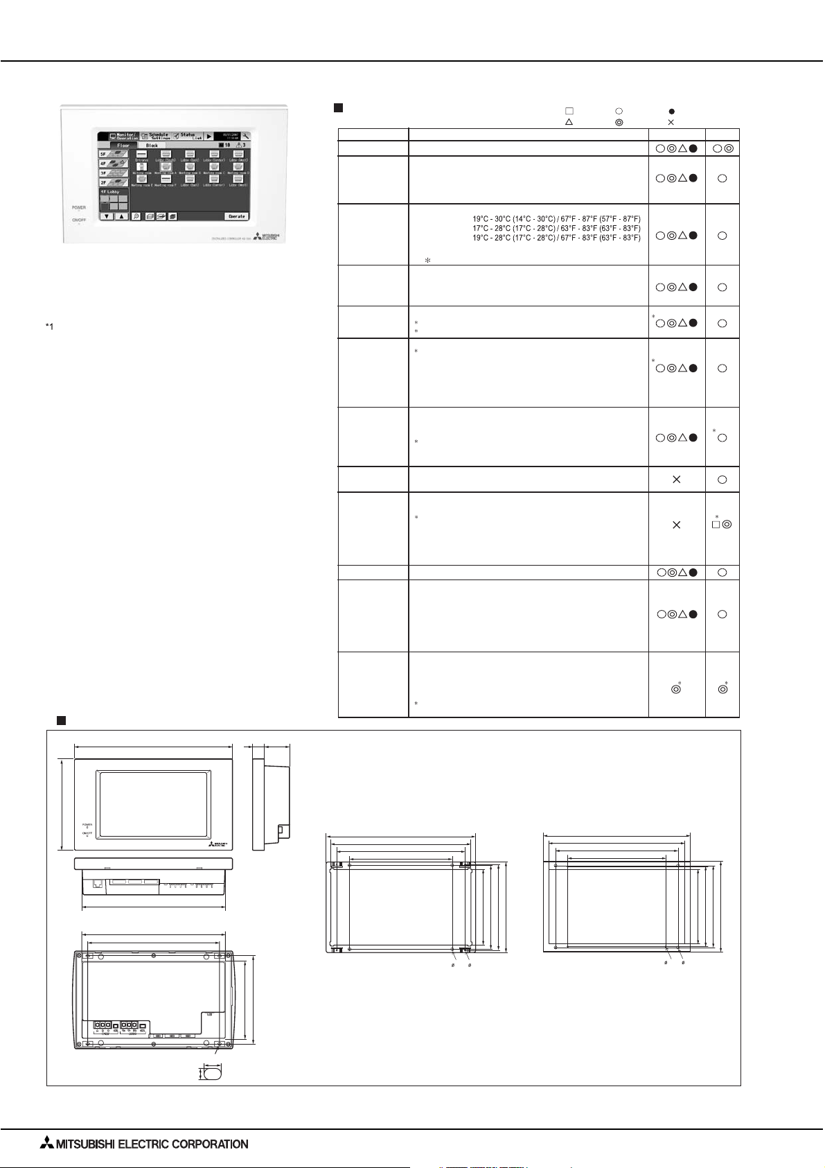
AG-150A features a 9"-wide color LCD touch panel.
The settings for air conditioning units can be
changed by touching the corresponding icons on
the display.
External dimension
25.6
44.7
(1-1/16)
300 (11-13/16)
(1-13/16)
Functions
Item
ON/OFF
Operation mode
switching
Temperature
setting
Fan speed setting
Air flow direction
setting
Schedule
operation
Permit / Prohibit
local operation
Indoor unit intake
temperature
Error
Test run
Ventilation
equipment
External
input/output
:Each unit
Description
Run and stop operation for the air conditioner units
Switches between Cool / Dry / Auto / Fan / Heat. (Group of
LOSSNAY unit : automatic ventilation/ vent - heat interchange/
normal ventilation)
Operation modes vary depending on the air conditioner unit.
Auto mode is the City Multi R2 and WR2 series only.
Range of temperature setting
Cool/Dry :
:
Heat
Auto :
( )
when using middle-temperature on PEFY-VMS/VMH-by setting DipSW7-1
to ON. Yet, PEFY-P-VMH-E-F is excluded.
Range of temperature settings vary depending on model.
Models with 5 air flow speed settings: Hi/Mid-2/Mid-1/Low, Auto
Models with 4 air flow speed settings: Hi/Mid/Low, Auto
Models with 2 air flow speed settings: Hi/Low
Fan speed setting (including Auto) varies depending on the model.
Air flow direction angles, 4-angle or 5-angle Swing, Auto
1: Louver cannot be set.
Air flow direction settings vary depending on the model.
Weekly schedule can be set for each group of air conditioning units.
2 By registering a license for AG-150A, weekly (2 types), annual, and current day
scheduling function become available.
The system follows either the current day, annual schedule, or weekly, which are
in the descending order of overriding priority.
Twenty-four events can be scheduled per day, including Start/Stop, Mode,
Temperature Setting, Operation Prohibition, Vane Direction, and Fan Speed.
Two types of weekly schedule (Summer/Winter) can be set.
Settable items depend on the functions that a given air conditioning unit supports.
Individually prohibit operation of each local remote control
function (Start/Stop, Change operation mode, Set temperature,
Reset filter).
3: When the local remote controller inactivation command is
received from the master system controller,
"Disabled"appears in inverted display on the operation setting screen.
Measures the intake temperature of the indoor unit only when
the indoor unit is operating.
When an error is currently occurring on an air conditioner unit,
the afflicted unit and the error code are displayed.
4: When an error occurs, the "ON/OFF" LED flashes. The
operation monitor screen shows the abnormal unit by flashing
it. The error monitor screen shows the abnormal unit address,
error code and source of detection. The error log monitor
screen shows the time and date, the abnormal unit address,
error code and source of detection.
This operates air conditioner units in test run mode.
The interlocked system settings can be performed by the master
system controller.
When setting the interlocked system, you can use the ventilation
switch to switch the free plan LOSSNAY settings between "Hi",
"Low" and "Stop".
When setting a group of only free plan LOSSNAY units, you can
switch between "Normal ventilation", "Interchange ventilation"
and "Automatic ventilation".
By using accessory cables you can set and monitor the following.
Input: By level signal: "Batch start/stop", "Batch emergency stop"
By pulse signal: "Batch start/stop", "Enable/disable local remote
controller"
Output: "Start/stop", "Error/Normal"
5: Requires the external I/O cable (PAC-YG10HA) sold
separately.
:Each floor :Not available
:Collective
:Each block:Each group
Operations Display
1
2
5
Unit:mm[in.]
3
4
5
185 (7-5/16)
272 (10-3/4)
Back View
272 (10-3/4)
250 (9-7/8)
CENTRALIZED CONTROLLER AG-150A
4.5(3/16)
8 (3/8)
167 (6-5/8)
146 (5-3/4)
A type installation plate B type installation plate
290.8 (11-1/2)
273 (10-3/4)
250 (9-7/8)
200 (7-7/8)
(1/4)
6
(3/16)
4
167 (6-5/8)
147 (5-13/16)
163.4 (6-7/16)
175.8 (6-15/16)
300 (11-13/11)
278 (10-15/16)
250 (9-7/8)
200 (7-7/8)
(3/16)
152 (6)
167 (6-5/8)
185 (7-5/16)
163.4 (6-7/16)
6
4
(1/4)
CONTROLLER Cntr- 2
Page 4
1. System remote controller
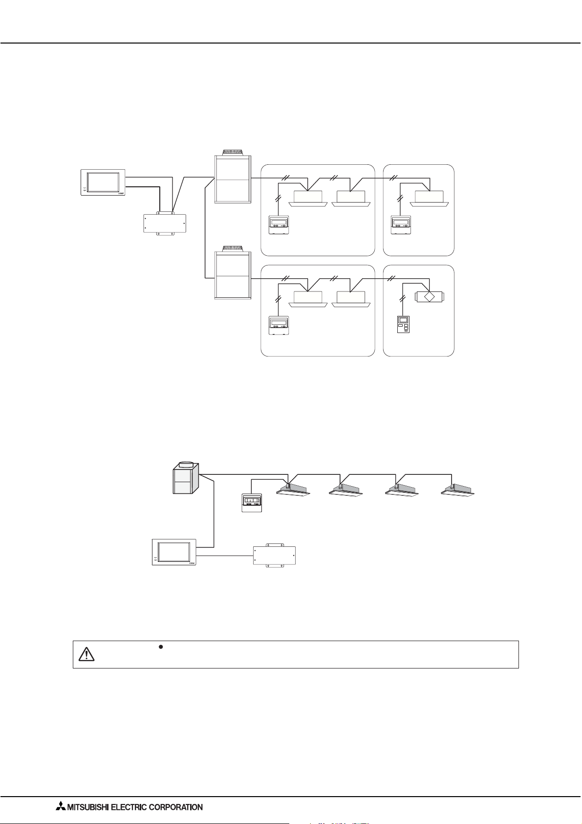
1. Power supply to AG-150A
AG-150A needs DC power supply of M-NET (24~32V) and 24V; the former is for centralized control transmission use and the
latter is for AG-150A's operating and LAN function use. AG-150A can have power-supply at following 1,2 methods.
(1). Power supply unit PAC-SC51KUA is the recommended power supplier for AG-150A. The basic scheme is as follows.
For details, please refer to Power supply unit PAC-SC51KUA.
Centralized controller
AG-150A
CENTRALIZED CONTROLLER AG-150A
24VDC
PAC-SC51KUA
(TB2 and TB3 used)
M-NET
TB2
ME remote
controller
ME remote
controller
M-NET
M-NET
ME remote
controller
LOSSNAY unit
PZ-52SF
Fig. 1 AG-150A and PAC-SC51KUA basic scheme.
(2). Power supply of 30VDC (M-NET) from connector of TB3 of Outdoor unit and PAC-SC51KUA.
AG-150A can also receive power supply from TB3 connector of the R410A or R407C, R22 Outdoor unit.Yet, Outdoor
unit down will lead down to AG-150A too. The kind of connection is possible but not recommended air conditioner
system of multiple Outdoor units. The 24VDC can be supplied at TB3 connector of PAC-SC51KUA.
CAUTION
Indoor/outdoor transmission line
TB3
CN41
PAC-SC51KUA
Centralized controller
AG-150A
CENTRALIZED CONTROLLER AG-150A
(TB3 24VDC used)
Fig. 2 AG-150A, TB3 and PAC-SC51KUA scheme.
When applying Charge and/or Peak-cut function on AG-150A, Power Supply Unit (PAC-SC51KUA) is recommended to use. AG-150A is
possible to receive power from the one of the Outdoor units, but there is a risk that the failure of power supply from the Outdoor unit will
cause AG-150A's function-down on the whole system.
CONTROLLER
Cntr- 3
Page 5
1. System remote controller
2. External input/output usage
(1). External signal input function
External signal input requires the external I/O adapter (Model: PAC-YG10HA) sold separately.
1). External input
Emergency stop/normal, run/stop and prohibit/permit of local remote controller operation can be controlled for all air
conditioners being controlled by using a voltage (12VDC or 24VDC) contact signal from an external source.
(Select with the function select setting.)
Function
No
1
Not in use
Emergency
2
(Level signal)
ON/OFF
3
(Level signal)
ON/OFF
prohibit/permit
4
(Pulse signal)
name
stop
External signal input function
Do not use external input signal
(factory setting)
Execute emergency stop/normal
with level signal
Perform ON/OFF with level signal
Perform ON/OFF, prohibit/permit
with pulse signals.
Remarks
The local remote controller ON/OFF operations, and the
controller ON/OFF operation and prohibit/permit change
operations will be prohibited during emergency stop.
Timer operation will also be prohibited.
The local remote controller ON/OFF operations, and the
controller ON/OFF operations and prohibit/permit change
operations will be prohibited.
Timer operation will also be prohibited.
Set the pulse width while the contact is ON to 0.5 to 1 sec.
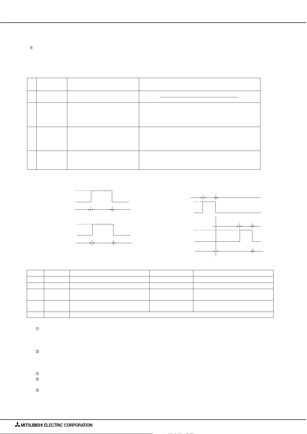
2). Level signal and pulse signal (12VDC or 24VDC)
(A) Level signal (B) Pulse signal
Contact ON
Contact OFF
Contact ON
Contact OFF
External input specifications
3).
Stop StopRun
Normal
Emergency stop
Normal
CN5 Lead wire Emergency stop/normal level signal
(Example) for ON/OFF
Signal 1 (run)
Contact ON
Contact OFF
Signal 2 (stop)
Contact ON
Contact OFF
*The prohibit/permit input is the same.
ON/OFF, level signal
0.5 to 1 sec
0.5 to 1 sec
OFF OFFON
ON/OFF, prohibit/enable pulse signal
No.5 Orange Emergency stop/normal input ON/OFF input ON input
No.6 Yellow Not used
No.7 Blue
No.8 Gray Not used
No.9 Red External DC source
Not used
Not used
Not used
Not used
“+ 12VDC” or “+ 24VDC”
OFF input
Local remote controller operation
prohibit input
Local remote controller operation
enable input
(A) For level signal
When the emergency stop/normal signal is selected, the status will change from normal to emergency stop when the
external input signal contact changes from OFF to ON, and will change from emergency stop to normal when the
contact changes from ON to OFF. Air conditioning units that came to an emergency stop will remain stopped after
the emergency stop is cancelled. Manually start up each unit to restore the previous operation.
When the ON/OFF signal is selected, the status will change from OFF to ON when the external input signal contact
changes from OFF to ON, and will change from ON to OFF when the contact changes from ON to OFF.
(B) For pulse signal
Even if the ON signal is input during ON, the status will remain ON.
If the local remote controller is prohibited, the ON/OFF operation mode and temperature setting operations by the
local remote controller will be prohibited.
Set the pulse width (contact ON time) to 0.5 to 1 sec.
CONTROLLER Cntr- 4
Page 6
1. System remote controller
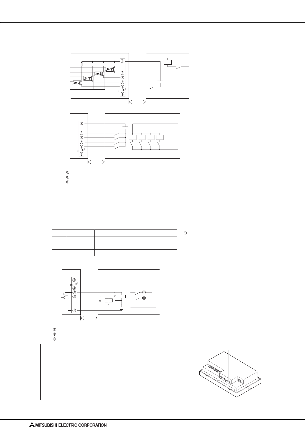
4). Recommended circuit example
(A) For level signal
CN5
Red
X1
Run/stop or
Emergency stop
X1
Power supply
(12VDC or 24VDC)
Use relays X1, X2, Y1, and Y2 that meet the
following specifications.
Contact rating
Rated voltage
Rated current
Minimum applicable load =< 1mA at DC
This unit
(B) For pulse signal
CN5
This unit
Red
Gray
Blue
Yellow
Orange
Max.10m
(32 ft)
Y2
Y1
X2
X1
Orange
Max.10m
(32 ft)
Power supply
(12VDC or 24VDC)
X1 X2 Y1 Y2
Run Stop Prohibit Enable
The contact relay, DC power source, extension cable, etc., must be prepared separately at the site.
The connection cable can be extended up to 10m (32 ft). (Use a 0.3mm2 (AWG 22) or larger wire.)
Strip the extra cable near the connector, and securely insulate the exposed section with tape, etc.
(2). External signal output function
* External signal output requires the external I/O adapter (Model: PAC-YG10HA) sold separately.
1). External output
When one or more air conditioners are running, the " ON " signal will be output and if a malfunction occurs in one or more air
conditioners, the " Malfunction " signal will be output.
2). External output specifications
CN5 Lead wire Details of each terminal
No.1 Green Common (External ground)
The " ON" signal is output even while the " Malfunction"
signal is being output.
No.2 Black ON/OFF
No.3 Brown Malfunction/normal
>= 12VDC
>= 0.1A
3). Recommended circuit example
CN5
This unit
Brown
Black
Green
Max.10m
(32 ft)
Diode(*2)
(*2)
Z1
Power
Supply
(*2)
Z2
(*1)
L1: Run display lamp
L2: Malfunction display lamp
Z1
L1
L2
Z2
Each element will turn on while ON operation or a malfunction occurs.
The connection cable can be extended up to 10m (32 ft).
The relays, lamps, diodes and extension cables, etc, must be prepared separately at the site.
NOTE
* When connecting the external input/output cables to connector CN5
on the controller, punch out the knockout hole.
Use Z1 and Z2 relays that meet the following specifications.
Operation coil
Rated voltage : 12VDC, 24VDC
Power Consumption: 0.9W or less
(*1) Prepare a power supply separately according to the relay
being used. (12VDC or 24VDC)
(*2) Always insert a diode on both ends of the relay coil.
Punch out the knockout hole
CONTROLLER
Cntr- 5
Page 7

1. System remote controller
3. LAN connection function
When using the LAN connection function, connect the LAN cable to the
LAN connector of this device.
Procure the LAN cable at the site, and use 100 BASE-TX Straight cable.
For a description of the IP address setting method, refer to Instruction Book.
LAN is 100 BASE-TX Specification.
NOTE
Perform the LAN wiring before installation, and wire up to the body by the same method as wiring the M-NET
transmission line.
When a LAN is already connected, decide the IP address by consultation with the system administrator and
connect to the LAN body after changing the IP address.
Connect AG-150A to a private network.
Use a security device such as a VPN router when connecting the AG-150A to the Internet to prevent
unauthorized access.
(If no security devices are installed, the operation settings may be changed by an unauthorized person
without the knowledge of the user.)
LAN
CONTROLLER Cntr- 6
Page 8

1. System remote controller
4. Browser screens of AG-150A
Condition List (Overview) Condition List (Block)
Operation
Malfunction List
Weekly 1 ScheduleMalfunction Log
CONTROLLER
Cntr- 7
Page 9

1. System remote controller
Operation (DIDO Controller)
Trend Graph (temperature/humidity) Trend Graph (Peak cut control)
Measurement status monitor (temperature
sensor/humidity sensor /measurement meter)
CONTROLLER Cntr- 8
Page 10

1. System remote controller
5. Liquid crystal displays of AG-150A
Floor layout screen Weekly schedule setting screen
Floor layout screen Annual schedule setting screen
Block display screen Operation screen
Error status screen Error history display screen
CONTROLLER
Cntr- 9
Page 11

1. System remote controller
1-2. Power supply unit [PAC-SC51KUA]
PAC-SC51KUA supplies DC power of 23-32V and 24V at TB2 and TB3 respectively; the former is for centralized transmission use
and the latter is for AG-150A operation and LAN function use.
1. When using PAC-SC51KUA as the power supplier for system controller, the capacity for system controller is
considered as follows.
CENTRALIZED CONTROLLER AG-150A
24VDC
Add : 201
Centralized control
transmission line
TB7
M-NET
TB7
Indoor/outdoor transmission line
CN41
Indoor/outdoor transmission line
CN41
LOSSNAY
Main SC
Add : 000
PAC-SC51KUA
(TB2 and TB3 used)
Sub SC
SC : System Controller
Lossnay can have its own Lossnay remote
controller, but the total quantity of the controllers
is limited.
Fig. 1 Equivalent power consumption of controllers
In this case, pay attention to leave the power supply switch connector on CN41 of the Outdoor unit as the factory setting
before shipment.
Taking the power consumption of the control board of Indoor unit as 1, the power consumption of various controllers is rated
at Table 1.
Table 1 Equivalent power consumption of controllers
Centralized controller
AG-15 0A
0.5
G-50A GB-50A
Not used
ON/OFF remote controlle r
(PAC-YT40ANRA)
*1
3
Other system controllers Remote controllers
System remote controller
(PAC-44SRA)
Schedule timer
( PAC-YT34STA)
10.5
ME remote controller
(PAR-F27MEA)
LOSSNAY remote controlle r
(PZ-52SF)
0.25
*1: G-50A cannot be connected to PAC-SC51KUA. Use PAC-SC50KUA to connect G-50A.
PAC-SC51KUA is capable to supply eqovalent power up to 5, therefore the maximum connectable number of system controller
is as follows.
Table 2 Max. connectable quianity of controller when using PAC-SC51KUA
Centralized controller
*2
Other system controllers Remote controllers
System remote controller ME remote controller
AG-150A G-50A GB-50A
ON/OFF remote controller
(PAC-YT40ANRA)
(PAC-44SRA) (PAR-F27MEA)
Schedule timer LOSSNAY remote controller
( PAC-YT34STA) (PZ-52SF)
1unit 1unit
Not used
*1
20 units5 units 10 units
*1: G-50A cannot be connected to PAC-SC51KUA. Use PAC-SC50KUA to connect G-50A.
*2: According to the system restrictions, PAC-SC51KUA can be connected to only one centralized controller.
As the air conditioner control system may combine all kinds of system controllers, the total power
consumption of system controllers need to count with Table 2.
For example, the controller system contain 1 AG-150A, 2 ON/OFF remote controllers (PAC-YT40ANRA),
1 schedule timer (PAC-TY34STA), 6 Lossnay remote controllers connected at centralized control
communication line.
Then the total power consumption is
1 x 0.5+2 x 1+1 x 0.5+6 x 0.25 = 4.5 < 5.
One PAC-SC51KUA is therefore enough. The total power consumption should not exceed 5.
CONTROLLER Cntr- 10
Page 12

1. System remote controller
2. When supply power to 1 AG-150A, the PAC-SC51KUA can supply power to other system controllers as follows.
Table3 Connectable number of system controller when 1 AG-150A is used.
V : Connectable
When connected to one AG-150A
Total number of
System remote controller(SR)
Schedule timer(ST)
When applying Charge and/or Peak-cut function on AG-150A, Power Supply Unit (PAC-SC51KUA) is recommended to use.
CAUTION
AG-150A is possible to receive power from one of the Outdoor units, but there is a risk that the failure of power supply from
the Outdoor unit will cause AG-150A's functiondown on the whole system.
0
1
2
3
4
5
6
7
8
9
10
Total number of ON/OFF remote controller(AN)
01 2 3 4 5
V
V
VVVV
VVVV
VV V V
VV V V
VV V
VV V
VV
VV
V
V
3. When supply power to 1 GB-50A, the PAC-SC51KUA can supply power to other system controllers as follows.
Table4 Connectable number of system controller when 1 GB-50A is used.
V : Connectable
Total number of ON/OFF remote controller(AN)
When connected to one GB-50A
Total number of
System remote controller(SR)
Schedule timer(ST)
0
1
2
3
4
5
01 2 3 4 5
V
V
VV
V
VV
V
V
6
7
8
9
10
When applying Charge and/or Peak-cut function on GB-50A, Power Supply Unit (PAC-SC51KUA) is recommended to use.
CAUTION
GB-50A is possible to receive power from one of the Outdoor units, but there is a risk that the failure of power supply from
the Outdoor unit will cause AG-150A's functiondown on the whole system.
CONTROLLER
Cntr- 11
Page 13

1. System remote controller
External dimension
Unit:mm[in.]
TB2,TB3
271(10-
90(3-
11
)
/
16
9
)
/
16
This device complies with Part15 of the FCCRules.Operation is
subject to the following two conditions:(1)this device may not cause
harmful interference,and(2)this device must accept any interference
received,including interference that may cause undesired operation.
UP
T
TB1
)
1
(
8
/
5-
130
)
1
(
8
/
6-
155
11
)
16
/
6-
(
169
72(2-
7
)
/
8
CONTROLLER Cntr- 12
Page 14

1. System remote controller
1-3. Integrated centralized control software [TG-2000A]
1. Example of Basic System Configuration.
*1
Web
monitor
license
Schedule
license
Energy
management
Uninterruptive
power supply (UPS)
Integrated
software installation
Input
etc.
ed control
CENTRALIZED CONTROLLER AG-150A
AG-150A
24VDC
Power supply unit
PAC-SC51KUA
3-phase 208/230V
(3-wire)
M-NET
This device complies with Part15 of the FCC Rules.Operation is
subject to the following two conditions: (1)this device may not cause
harmful interference, and (2)this device must accept any interference
received, including interference that may cause undesired operation.
PI Controller
(PAC-YG60MCA)
Outdoor unit system
watt-hour meter
Centralized controller
personal computer
TG-2000A
Single-phase 208/230V
Single-phase 208/230V
PLC (PAC-YG21CDA)
Indoor unit system
[ 24 VDC Power Supply]
watt-hour meter
Indoor unit
watt-hour meter
The electr ic amount count softw are or separately
procured par ts must be used with the designated PLC .
power source
Indoor unit system watt-hour meter
Indoor unit watt-hour meter
Outdoor unit system watt-hour meter
PLC (with electric amount count software)
RS-485WHM
Indoor unit system
Power
source
RS-232C
Centralized controller
personal computer
TG-2000A
Outdoor unit system
RS-485
Converter
watt-hour meter
Indoor unit
watt-hour meter
watt-hour meter
G-50A or GB-50A
*1
can be used.
When connecting
to the G-50A, use
PAC-SC50KUA.
The TG-2000A can realize the following functions
using the AG-150A or G-50A/GB-50A option (license).
Operation/monitor
Annual/weekly schedule
Charge
Energy saving
Peak cut
Note : Depending on the versions of TG-2000A and
Main features of TG-2000A
1
Up to 2000 indoor units (40 G-50A ,GB-50A, or AG-150A units) can be operated and monitored simultaneously.
2
The air-conditioner layout can be displayed on the screen, making control and operation easier.
3
The annual and weekly schedules can be set. 5 schedules, such as the summer master and winter master, can be
G(B)-50A, some of the functions may not be available for use.
saved in the weekly schedule.
4
Air-conditioning charges can be calculated based on the multiple air-conditioner usage results. The power apportionment
percentage data and apportioned power rate can be calculated for each indoor unit using the power apportionment
function, and can be output as a CSV format file.
:
Charging without WHM The user manually inputs the power rate to calculate the air-conditioning charges. (Using a tool)
RS-485 WHM charging The RS-485 WHM value is automatically tabulated to calculate the air-conditioning charges.
PLC + pulse WHM charging
PI controller + pulse WHM charging
1
:
1
The pulse output WHM value is automatically tabulated by the PLC to calculate the air-conditioning charges.
:
1
:
1
The pulse output WHM value is automatically tabulated by the PI controller (PAC-YG60MCA) to
Power apportionment charging is not possible with the old model, A control or K control.
calculate the air conditioning charges.
5
Energy saving operation is possible using the "ON/OFF", "set temperature change", "fan operation changeover" and
"performance save operation (60% to 90%)" functions.
Energy saving operation matching the amount of power in use is possible by using the PLC's electric amount count
software.
6
Night Set-Back function operation is possible with schedule settings. 2
7
General equipment can be operated and monitored.
8
General equipment can be schedule-controlled when using PAC-YG21CDA with PLC or DIDO Controller (PAC-YG66DCA).
(For details of PLC refer to Installation Manual of PAC-YG21CDA.)
1:
Only one of these functions can be used.
2:
With Night Set-Back function, the CITY MULTI system can run at heating mode with target temperature set to 12°C / 54°F under
schedule control. (It depends on the outdoor unit model.) This function can protect the room from dropping down to extremely low temperature at mid-night.
Note: AG-150A (Ver.1.** series) will be compatible with TG-2000A Ver.5.5* or later.
Depending on the versions of TG-2000A and AG-150A/G(B)-50A, some of the functions may not be available for use.
CONTROLLER
Cntr- 13
Page 15

1. System remote controller
2. List of TG-2000A functions
(1). The data for each AG-150A can be grouped and used to control the operation of up to 2000 units in floor or block units,etc.,
from the personal computer screen. By using a PLC/PI Controller or a watt-hour meter, the power rate can be apportioned,
energy saving control can be executed, and other general equipment can be controlled.
List of integral software functions
AG-150A license
Web monitor
Schedule
Energy
management
Item Details
PLC for
general equipment
ON/OFF
Operation modes
Temperature setting
Fan speed
Air direction
Interlocked unit ON/OFF
(LOSSNAY)
Local operation
prohibit
Annual / weekly
schedule
Power rate
apportionment charging
(power rate manual input)
Power rate
apportionment charging
History
Operation time monitor
Filter sign display
mask
Energy saving
control
Energy saving
(peak cut)
Night Set-Back function
Set temperature
limit
2
Control other general
equipment
With Night Set-Back function, the CITY MULTI R410A system (Not applicable to the PUMY model) can run at heating mode with target temperature set to 12°C/54°F under schedule setting.
1 :
(PUMY model does not support this function. Set the temperature within the range controllable via a remote controller under schedule setting.)
This function can protect the room from dropping down to extremely low temperature at midnight.
2 : This function cannot be used with the MA remote controller. (It depends on the indoor unit model.)
Note : Depending on the versions of TG-2000A and AG-150A, some of the functions may not be available for use.
The units can be turned ON and OFF for all floors or in block, floor or group units.
The general equipment can be turned ON and OFF.
( A PLC and the general equipment control PLC software required.)
The operation mode can be switched between COOL, DRY, FAN, AUTO and
HEAT for all floors or in block, floor or group units.
The room temperature can be set for all floors or in block, floor or group units.
Set temperature range COOL / DRY : 19°C to 30°C / 67°F to 87°F
HEAT : 17°C to 28°C / 63°F to 83°F
AUTO : 19°C to 28°C / 67°F to 83°F
The fan speed can be set to four stages for all floors or in block, floor or group units.
The air direction can be set in four vertical directions or to swing for all floors or in block,
floor or group units.(The selectable air direction differs according to the model.)
If there is an interlocked unit (LOSSNAY, the unit can be turned ON (strong/weak) or OFF for all floors
or in block, floor or group units. (Note that the ventilation mode cannot be selected for interlocked units.)
The items for which operation with the local remote controller are to be prohibited can be selected for
all floors or in block, floor or group units. (The items that can be prohibited are ON/OFF, operation mode,
set temperature and filter sign reset.)
The annual/weekly (season:weekly x 2) schedule function can be used by registering the license.
Five settings, such as seasonal settings for summer and winter, can be saved.
By registering the G-50A unit license number, the power rate apportionment percentage data
for each indoor unit can be output in CSV format. The power rate for each tenant can be easily
calculated by having each user input the power rate manually.
By using the PI controller (PAC-YG60MCA) and a pulse output watt-hour meter, the air-conditioning
charges can be calculated based on the amount each tenant's air-conditioner has operated. Up to
five charging rates can be applied per day.
By using a PLC (with electric amount count software) and a watt-hour meter with pulse transmitter,
the air-conditioning charges can be calculated based on the amount each tenant's air-conditioner has
operated.Up to five charging rates can be applied per day.
An RS-485 watt-hour meter is connected to calculate the air-conditioning charges based on the
amount each tenant's air-conditioner has operated. Two charging rates can be applied per day.
The error history and up to 10000 items for operation history can be saved.
can be output as a daily report or monthly report in CSV format.
The maximum number of error history data that can be saved depends on the type of errors and the number of connected AG-150A units.
The operation history consists only of the operations carried out with the TG-2000A, and is limited to some limited operation items.
The cumulative operation time of each indoor unit can be viewed or output as a CSV format file.
(This function is valid only when the charging function license is registered.)
Automatic display of the filter sign can be disabled. (System batch.)
In this case, the filter sign state is confirmed with manual operations .
Energy saving operation is possible using the "ON/OFF", "set temperature change", "fan operation
changeover" and "performance save operation" functions.
Energy saving operation matching the amount of power in use is possible.
(PLC (with electric amount count software) and watt-hour meter with pulse transmitter are required.)
Heating from 12°C / 54°F and higher can be set using the schedule.
1
The set temperature lo
(Valid only when PAR-F27MEA is used.)
The ON/OFF status of the connected general equipment and the error status can be
changed or monitored from the DIDO(PAC-YG66DCA).
It is possible to control other general equipment on ON/OFF operation / monitoring / Alarm /
scheduling, if TG-2000A combines PLC installed with PLC software PAC-YG21CDA.
Setting inter-lock with CITY MULTI indoor units is possible using PLC(PAC-YG21CDA).
(Table setting tool for input/output definition is needed.)
wer limit can be set for cooling and the upper limit for heating.
Depend on the model
Each history file
V
V
V
V
V
V
V
V
VV
V
V
V
V
V
VV
V
V
V
V
VV
V
V
V
V
CONTROLLER Cntr- 14
Page 16

1. System remote controller
3. Browser screens of TG-2000A
Floor screen
Weekly schedule screen
Block screen
All floor screen
Annual schedule screen
Operation setting screen
Air-conditioning charge screen
CONTROLLER
Cntr- 15
Page 17

1. System remote controller
4. Requirements (system recommendations)
We recommend the following software and hardware when using this application (TG-2000A).
TG-2000A version System Requirements
When AG-150A/G-50A-compatible
TG-2000A is used
When G-50A-compatible TG-2000A
is used with the range of conventional functions
*1 : TG-2000A Ver.5.20 is upgraded to Ver.5.50.
Item Requirement Recommended
PC
PC/AT interchangeable machine
(Recommended: IBM, HP,DELL)
TM
2 Duo 1.66GHz or faster
CPU
Core
(Windows Vista for Core 2 Duo)
Pentium® M 1.7GHz or faster Pentium® M 2.0GHz or faster
Pentium® 4 2.4GHz or faster Pentium® 4 2.8GHz or faster
Memory
HDD
In
Windows Vista : 1GB or more 2GB or more
In
Windows XP / 2000 : 512MB or more 1GB or more
Standard
6GB or more (2GB or more of C
drive free space necessary)
20GB or more (Free space)
Storage device
Resolution
Serial port
LAN
Wide area
CD-ROM drive, USB drive
1024 x 768 or higher, 65536 colors or more
1 port or more
1 port (10BASE-T/100BASE-TX) * 1
Modem 56K modem or TA
USB 2 port or more
OS
Windows
® Vista Business
Service Pack 1
Windows
® XP Professional
Service Pack 3 *2
Windows
® 2000 Professional
Service Pack 4 *2
Other
Computer must be dedicated for this use
(TG-2000A).
*1 Purchase the option, or use the equipment recommended for the computer when purchasing the computer.
*2 Make sure that the correct version of Service Pack is installed. If the wrong version of Service Pack is installed, TG-2000A will not be set up properly.
TG-2000A Ver.5.50 or later *1
TG-2000A Ver.5.16 or later
Operation check completed, using IBM, HP and
DELL(Business model is recommended)
CoreTM 2 Duo 2.4GHz or faster
40GB or more of C
When using the trend function, the drive used for
automatic output must have the following free
space according to the number of groups.
200 groups = 2GB, 500 Groups = 5GB, 1000
groups = 10GB, 2000 groups = 20GB
Standard : max. 200MB/site
Devices other than those shown at the left may also
be installed.
Required when using RS-485 communication WHM
(Not necessary when using PLC or PI Controller)
Required when using a modem in wide area mode.
It uses it for the data backup.
English version only
*Computer must support each OS.
English version only
*Computer must support each OS.
English version only
*Computer must support each OS.
Must be used for 24-hour constant operation
(Only some functions. Refer to the TG-2000A manual for details.)
OS : Windows Vista/XP
Refer to the table below for details.
OS : Windows XP/2000
Refer to the table below for details.
drive free space necessary
CONTROLLER Cntr- 16
Page 18

5. Compatible Units
The TG-2000A has two main functions: centralized control of air conditioners and cost accounting. However, not all
functions are available with all air conditioners. (TG-2000A Ver.5.16 / 5.50 or later)
Table: Compatible units and function list ( : supported, : Certain restrictions apply, : Not supported)
As of Ver.5.16 / 5.50
Function
Model
Y series
R2 series
WR2 series
WY series
Multi S series
Indoor unit
LOSSNAY
OA processing unit
"A" control type
"K" control type
4
4
Room air Conditioner
Air To Water Booster
unit
Air To Water HEX unit
1 : Can be calculated for each charging block. May not be available with some older models.
2 : Indoor unit models before Free Plan models do not support a charge apportioning billing method based on the “capacity save”. The existence of even a single unit of
those types in the system requires that the method of charge apportioning billing be set to either “Thermo on time” or “Fan operation time”.
Certain restrictions apply to larger capacity indoor units when malfunctions occur.
3 : LOSSNAY groups to which the remote controller is connected support the charging system.
4 : Not all of the A-control and K-control units support these functions. The calculation of the charge for the auxiliary heater may not be handled by these units.
5 : Outdoor unit capacity control function is not available.
6 : Only the function to stop the units is available.
7 : When the attribute is IC (indoor unit): Same type of energy-save control unit as with the Free Plan Indoor unit is possible.
When the attribute is FU (LOSSNAY with heater and humidifier): No direct energy-save control is possible.
8 : Inverter models support the outdoor unit capacity save control function.
9 : Outdoor unit Thermo-OFF control function is not supported. Only the fan control function is available.
10: Only the temperature control function or the function to stop the units is available.
11: For A-control and K-control units, use the apportioned charging methods that are listed in "Thermo on time" or "Fan operation time" section.
Otherwise, install an watt-hour meter for each unit.
Control/
Maintenance
(Adapter required)
(Converter required)
(Adapter required)
Charging (Billing)
without WHM
Charging (Billing) with WHM
1
1
1
1
1
2
3
1
1,11
1,11
(Requires separate watt
hour meters. Bill calculated
based on the reading of
each watt hour meter.)
DATA C3
Energy
Saving/
Peak Cut
5
6
7
8
9
10
CONTROLLER Cntr- 17
Page 19

DATA BOOK AG-150A
PAC-SC51KUA
Issued in Nov. 2008 MEE08K039
Printed in Japan
HEAD OFFICE: TOKYO BLDG., 2-7-3, MARUNOUCHI, CHIYODA-KU, TOKYO 100-8310, JAPAN
New publication effective Nov. 2008.
Specifications subject to change without notice.
 Loading...