

Page 1

MOTION CONTROLLER
User’s Manual
type A173UHCPU,A172SHCPUN,
A171SHCPUN
MITSUBISHI
ELECTRIC
Page 2
INTORODUCTION
Thank you for purchasing the Mitsubishi Motion Controller/A173UHCPU/A172SHCPUN/ A171SHCPUN.
This instruction manual describes the handing and precautions of this unit. Incorrect handing will lead to
unforeseen events, so we ask that you please read this manual thoroughly and use the unit correctly.
Please make sure that this manual is delivered to the final user of the unit and that it is stored for future
reference.
Precautions for Safety
Please read this instruction manual and enclosed doc uments before starting installation, operation, maintenance or inspections t o ensure correct usage. Thoroughly underst and the machine,
safety information and prec aut i ons before starting operation.
The safety precautions are ran ked as "Warning" and "Caution" in th is instruction manual.
WARNING
CAUTION
Note that some items described as cautions may lead to ma jor results depending on the
situation. In any case, import ant information that must be observed is described.
When a dangerous situation may occur if handling is mistaken
leading to fatal or m a j o r injuries.
When a dangerous situation may occur if handling is mistaken
leading to medium or minor injuries, or physical damage.
− I −
Page 3
For Sate Operations
1. Prevention of electric shocks
Never open the front case or ter minal covers while the power is ON or the unit is running, as
this may lead to electric shocks.
Never run the unit with the front ca se or t erminal cover removed. The high voltage terminal
and charged sections will be exposed and may lead to electric shocks.
Never open the front case or terminal cover at times other than wiring work or per iodic
inspections even if the power is O FF. The insides of the control u nit and servo amplifier are
charged and may lead to electric shocks.
When performing wiring wor k or inspections, turn the power OFF, wait at least ten minutes,
and then check the voltage wit h a t est er, et c. Failing to do so may lead to electric shocks.
Always ground the control unit, servo amplifier and servomotor wit h C la ss 3 grounding. Do
not ground commonly with other devices.
The wiring work and inspections must be done by a qualified technician.
Wire the units after installing the control unit, servo ampli f ier and servomotor. Failing to do
so may lead to electric shocks or damage.
Never operate the switches w it h w et hands, as this may lead to electr ic shocks.
Do not damage, apply excessive stress, place heavy t hings on or sandwich the cables, as
this may lead to electric shocks.
Do not touch the control unit, servo amplifier or servomotor terminal blocks while the power
is ON, as this may lead to electric shocks.
Do not touch the interna l power supply, internal grounding or signal wires of the control unit
and servo amplifier, as this may lead to electric shocks.
WARNING
2. For fire prevention
Install the control unit, serv o amplifier, servomotor and regenerat ive resistor on inflammable
material. Direct installation on flammable material or near flammable mater ia l may lead to
fires.
If a fault occurs in the control unit or serv o amplifier, shut the power OFF at the serv o
amplifier’s power source. If a large current continues to flow, fires may occur.
When using a regenerative resist or, shut t he pow er OFF with an error signal. The regenerative resistor may abnormally ov erheat due to a fault in the regenerative t r ansist or, et c. , and
may lead to fires.
Always take heat measures suc h as f lame proofing for the inside of the control panel where
the servo amplifier or regenerative resistor is installed and for the w ires used. Failing to do
so may lead to fires.
CAUTION
− II −
Page 4
3. For injury prevention
CAUTION
Do not apply a voltage other than that specified in the instruction manual on any t erminal.
Doing so may lead to destruct ion or damage.
Do not mistake the termina l connections, as this may lea d t o dest r uct i on or damage.
Do not mistake the polarity (+ / -), as this may lead to destruction or damage.
The servo amplifier's heat radiat i ng f ins, regenerative resistor and servo amplifier, etc., will
be hot while the power is ON and for a short time after the power is turned OFF. Do not
touch these parts as doing so may lead t o burns.
Always turn the power OFF before touching the servomotor shaft or coup led machines, as
these parts may lead to injuri es.
Do not go near the machine dur ing t est operations or during operat ions such as teaching.
Doing so may lead to injuries.
4. Various precautions
Strictly observe the following precautions.
Mistaken handling of the unit may lead to faults, injuries or electric shocks.
(1) System structure
CAUTION
Always install a lea ka ge breaker on the control unit and serv o amplifier power source.
If installation of a magnetic co nt act or for power shut off during an error, etc., is specified in
the instruction manual for t he servo amplifier, etc., always inst all the magnetic contactor.
Install an external emergen cy stop circuit so that the operation c an be st opped immediately
and the power shut off.
Use the control unit, servo a mpli fier, servomotor and regenerative resistor w ith t he combi-
nations listed in the instruct ion manual. Other combinat ions may lead to fires or faults.
If safety standards (ex., robot safety rules, etc.,) apply to the syst em using t he control unit,
servo amplifier and servomotor, make sure that the safety standards are sat is fie d.
If the operation during a control unit or servo amplifier error and the safety direction
operation of the control unit di ffer, const r uct a countermeasure circuit externally of the
control unit and servo amplifi er.
In systems where coasting of the serv omot or w ill be a pro bl em during emergency stop,
servo OFF or when the power is shut O FF, use dynamic brakes.
Make sure that the system considers the coasting amount even when using dynamic
brakes.
In systems where perpendicular shaft dropping may be a problem dur ing emergency stop,
servo OFF or when the power is shut O FF, use both dynamic brakes and magnetic brakes.
The dynamic brakes must be used only during emergency stop and errors where servo OFF
occurs. These brakes must not be us ed f or normal braking.
The brakes (magnetic brakes) assembled into the servomotor are for holding applications,
and must not be used for normal braki ng.
Construct the system so that t here is a mechanical allow ance allowing stopping ev en i f the
stroke end limit switch is pass ed t hrough at the max. speed.
Use wires and cables that have a w ire d ia m et er, heat resistance and bending resistance
compatible with the system.
− III −
Page 5
Use wires and cables within the length of the range described in the instruction manual.
The ratings and characteristics o f the system parts (other than control unit, servo amplifier,
servomotor) must be compatible w ith t he control unit, servo amplifier and serv omot or.
Install a cover on the shaft so that t he rot ary parts of the servomotor are not touched during
operation.
There may be some cases where hol ding by the magnetic brakes is not possible due to the
life or mechanical structure (when the ball screw and servomotor are connected with a
timing belt, etc.). Install a stopping device to ensure safety on the machine side.
(2) Parameter settings and programming
Set the parameter values to those that are compatible with the control unit, servo amplifier,
servomotor and regenerative resistor model and the system applicati on. The protective
functions may not function if the settings are incorrect.
The regenerative resistor model and capacity parameters must be set to values that
conform to the operation mode, servo amplifier and servo power unit. Th e prot ect ive
functions may not function if the settings are incorrect.
Set the mechanical brake output and dynamic brake output validity parameters to values
that are compatible with the system application. The protective functions may not fu nct ion if
the settings are incorrect.
Set the stroke limit input v al idit y parameter to a value that is compatible with the system
application. The prote c t ive functions may not function if the setting is incorrect.
Set the servomotor encoder type (incre ment , absolute position type, etc.) parameter t o a
value that is compatible w ith the system application. The prot ective functions may not
function if the setting is incorrect.
Set the servomotor capacity and t ype (standard, low-inertia, flat, etc. ) paramet er t o values
that are compatible with the system application. The protective functions may not fu nct ion if
the settings are incorrect.
Set the servo amplifier capacity and type parameters to values that are compatible with the
system application. The protect ive functions may not function if the set t i ngs are incorrect.
Use the program commands for t he program with the conditions spec if ied in the instruction
manual.
Set the sequence function pro gram capacity setting, dev ice capacity, latch validity range, I/O
assignment setting, and v alidity of continuous operat i on during error detection to values t hat
are compatible with the syst em application. The protective functions may not function if the
settings are incorrect.
Some devices used in the program have fixed applicati ons, so use these with the conditions
specified in the instructi on manual.
The input devices and data registers assigned to the link will hold t he data previous to when
communication is terminat ed by an error, etc. Thus, an error correspondence int erlock
program specified in the instruction manual must be used.
Use the interlock program specified in the special func t io n unit's instruction manual for the
program corresponding to the special function unit.
CAUTION
CAUTION
− IV −
Page 6
(3) Transportation and installation
Transport the product with the correct method according to the weight.
Use the servomotor suspension bolts only for the transportatio n of the servomotor. Do not
transport the servomotor with mac hine installed on it.
Do not stack products past the l i mit.
When transporting the control unit or servo amplifier, never hold the connected wires or
cables.
When transporting the servomotor, never hold the cables, shaft or detector.
When transporting the control unit or servo amplifier, never hold t he fr ont case as it may fall
off.
When transporting, installing or removing the control unit or servo amplifier, never hold the
edges.
Install the unit according to the instruction manual in a place where the weight can be withstood.
Do not get on or place heavy objects on the product.
Always observe the installation direction.
Keep the designated cleara nce between the control unit or serv o amplifier and control panel
inner surface or the control unit and s ervo amplifier, control unit or serv o amp l ifier and other
devices.
Do not install or operate cont rol units, servo amplifiers or servomotors that are damaged or
that have missing parts.
Do not block the intake/outt ake ports of the servomotor with cooling fan.
Do not allow conductive matter such a s screw or cut t in g chi ps or combustible matter such
as oil enter the control unit, serv o amp lifier or servomotor.
The control unit, servo amplifier and servomotor are precision machines, so do not drop or
apply strong impacts on the m.
Securely fix the control unit a nd servo amplifier to the machine according to the instruction
manual. If the fixing is insufficient, these may co me off duri ng operation.
Always install the servomotor with reduction gears in the designated direction. Fai ling t o do
so may lead to oil leaks.
Store and use the unit in the following environmental conditions.
CAUTION
Environment
Ambient
temperature
Ambient humidity
Storage
temperature
Atmosphere
Altitude 1000m (3278.69ft.) or less above sea level
Vibration According to each instruction manual
Control unit/servo amplifier Servomotor
0°C to +55°C
(With no freezing)
According to each instruction
manual.
According to each instruction
manual.
Indoors (where not subject to direct sunlight).
No corrosive gases, flammable gases, oil mist or dust must exist
− V −
Conditions
0°C to +40°C
(With no freezing)
RH or less
80
%
(With no dew condensation)
C to +65°C
−20°
Page 7
When coupling with the synchronization encoder or servomotor shaft end, do not apply
impact such as by hitting with a hammer. Doing so may lead to detector damage.
Do not apply a load larger than the t olerable load onto the servo motor shaft. Doing so may
lead to shaft breakage.
When not using the unit for a long ti me, disconnect the power line from the control unit or
servo amplifier.
Place the control unit and servo amplifier in static electric it y preventing vinyl bags an d st ore.
When storing for a long time, please co nsult our sales representative.
(4) Wiring
Correctly and securely w ire the w ires. Reconfirm the connection s for mist akes and the
terminal screws for tightness after w iring. Failing to do so may lead to run away of the
servomotor.
After wiring, install the prote ct ive covers such as the terminal cov ers t o t he original positions.
Do not install a phase adv ancing capacitor, surge absorber or radio noise filter (option FR-
BIF) on the output side of the servo amplifier.
Correctly connect the output side (terminals U, V, W). Incorrect connections will lead the
servomotor to operate abnormally.
Do not connect a commercial power supply to the serv omotor, as t his may lead to trouble.
CAUTION
CAUTION
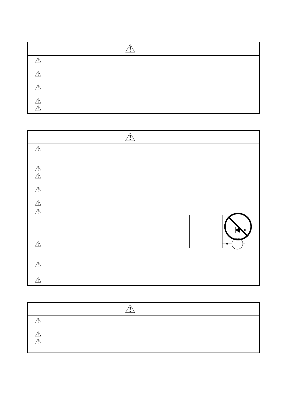
Do not mistake the direction o f the surge absorbing diode
installed on the DC relay for the c ont rol signal output of
brake signals, etc. Incorrect installation may lead to signals
not being output when trouble occurs or the protective
functions not functioning.
Do not connect or disconnect the connection cables
between each unit, the encoder cable or sequence expansion cable while the pow er is ON.
Securely tighten the cable co nnector fixing screws and fixing mechanisms. Insufficient fixing
may lead to the cables combing off during operation.
Do not bundle the power lin e or cables.
(5) Trial operation and adjustment
Confirm and adjust the progra m a nd each parameter before operation. U npredictable
movements may occur depend ing on the machine.
Extreme adjustments and changes may lead to unstable operation, so never make them.
When using the absolute posit ion system function, on starting up, and when the controller or
absolute value motor has been repla ced, always perform a home position return.
CAUTION
Servo amplifier
VIN
(24VDC)
Control output
signal
RA
− VI −
Page 8
(6) Usage methods
Immediately turn OFF the pow er i f s m oke, abnormal sounds or odors are em it t ed from the
control unit, servo amplifier or servomotor.
Always execute a test operat ion before starting actual operatio ns after the program or
parameters have been changed or after maintenance and inspection.
The units must be disassembl ed and repaired by a qualified techn ici an.
Do not make any modifications t o t he unit.
Keep the effect or magnetic obstacles to a minimum by insta l ling a noise filter or by using
wire shields, etc. Magnetic obsta cl es may affect the electronic devic es used near the control
unit or servo amplifier.
When using the CE Mark-compli ant equipment, refer to the "EMC Insta llation Guidelines"
(data number IB(NA)-67339) for the motion contro ll ers and refer to the corresponding EMC
guideline information for the servo amplifiers, inverters and ot her equipment.
Use the units with the fo llowing conditions.
Item
Input power
Input frequency 50/60Hz 5%
Tolerable momentary
power failure
CAUTION
Conditions
A1S61PN A1S62PN
100 to 240VAC
(85 to 264VAC)
Within 20ms
CPU module's built-
in power supply
+10%
-15%
(7) Remedies for errors
If an error occurs in the self diagnosis of the c ont rol unit or servo amplifier, confir m the
check details according to the instruct i on manual, and restore the operation.
If a dangerous state is predicted in case of a power failure or product failure, use a
servomotor with magnetic brakes or i nst al l a brake mechanism externally .
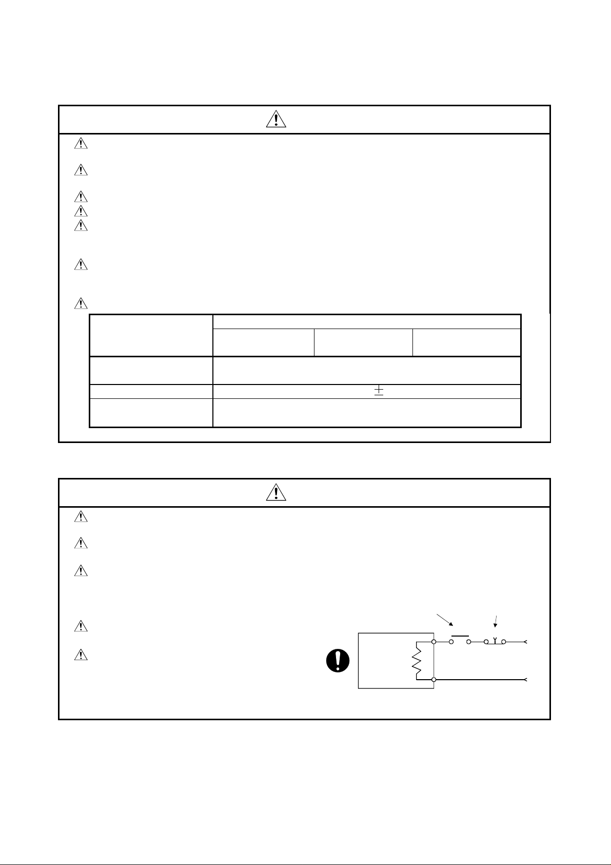
Use a double circuit construction so that the
magnetic brake operatio n circuit can be
operated by emergency stop signa ls set
externally.
If an error occurs, remove the cause, secure
the safety and then resume operat ion.
The unit may suddenly resume operation
after a power failure is restored, so do not go
near the machine. (Design the machine so
that personal safety can be ensure d even if
the machine restarts suddenly . )
CAUTION
Shut off with servo ON signal OFF,
alarm, magnetic brake signal.
Servo motor
Magnetic
brakes
RA1
Shut of f with th e
emergency stop
signal(EMG).
EMG
24VDC
− VII −
Page 9
(8) Maintenance, inspection and part replacement
CAUTION
Perform the daily and pe riodic inspections according to the instruction manua l.
Perform maintenance and insp ect io n after backing up the program and para meters for the
control unit and servo amplifi er.
Do not place fingers or hands in the c learance when opening or closing any opening.
Periodically replace consumable parts such as batteries a ccording to the instruction manual.
Do not touch the lead sections such as ICs or the connector contacts.
Do not place the control unit or servo amplifier on metal that may cause a power leakage or
wood, plastic or vinyl that may cause static electricity buildup.
Do not perform a megger test (insulat i on resistance measurement) during inspection.
When replacing the control unit or servo amplifier, always set the new unit set t in gs correctly.
When the controller or absolute value mot or has been replaced, carry out a home positi on
return operation using one of the f ol lowing methods, otherwise p osition displacement cou ld
occur.
1) After writing the servo data to the P C using peripheral device softw are, switch on the
power again, then perform a ho me position return operation.
2) Using the backup function o f the peri pheral device software, load t he dat a backed up
before replacement.
After maintenance and inspections are complete d, confirm that the position detection of the
absolute position detector funct ion is correct.
Do not short circuit, charge, overheat, incinerate or disassemble the bat t eries.
The electrolytic capacitor will generate gas during a fault, so do not place your face near t he
control unit or servo amplifi er.
The electrolytic capacito r and fan will deteriorate. P eriodically change thes e t o prevent
secondary damage from faults. Replacements can be made by our sales representative.
(9) Disposal
Dispose of this unit as general industrial waste.
Do not disassemble the control unit , servo amplifier or servomotor parts.
Dispose of the battery accordi ng t o local laws and regulations.
(10) General cautions
All drawings provided in the instruction manual show t he st ate with the covers and safety
partitions removed to explain detai led s ect i ons. When operating the product, always return
the covers and partitions to the designated positions, and operat e according to the
instruction manual.
CAUTION
CAUTION
− VIII −
Page 10
Revisions
*The manual number is given on the bottom left of the back cover.
Print Date *Manual Number Revision
Apr.1998 IB(NA)-67395-B First edition
Sep.2000 IB(NA)-67395-C
Addition
Addition of information on the A173UHCPU
Correction
For Sate Operations (4. Various precautions (3), (6), (8)), CONTENTS, 1.1,
1.2.1, 1.2.2, 1.3, 1.4, 1.5.1, 1.5.2 (1), 1.5.3, 1.5.4, 1.5.5, 1.5.6, 2.1, 2.3, 2.3.1,
2.3.2 (2), 4.3, 4.4, 5.4.1, 5.4.1(3), 5.4.1 (4), 5.4.1 (5), APPENDICES
Delete
1.5.7 (2), 5.3.1 (2)
This manual confers no industrial property rights or any rights of any other kind, nor does it confer any patent
licenses. Mitsubishi Electric Corporation cannot be held responsible for any problems involving industrial
property rights which may occur as a result of using the contents noted in this manual.
© 2000 Mitsubishi Electric Corporation
Page 11

CONTENTS
1. SPECIFICATIONS OF MOTION SYSTEM COMPONENTS.....................................................1- 1 to 1-57
1.1 Overview of the Motion System ......................................................................................................... 1- 1
1.2 Overall Configuration of Motion System ............................................................................................ 1- 3
1.2.1 A172SHCPUN/A171SHCPUN System Overall Configuration....................................................1- 3
1.2.2 A173UHCPU System Overall Configuration ............................................................................... 1- 5
1.3 Equipment in System.........................................................................................................................1- 7
1.4 General Specifications......................................................................................................................1-10
1.5 Specifications and Settings of Components ..................................................................................... 1-11
1.5.1 A173UHCPU/A172SHCPUN/A171SHCPUN............................................................................. 1-11
1.5.2 Extension Base Power Supply Module ...................................................................................... 1-25
1.5.3 Base Units and Extension Cables.............................................................................................. 1-28
1.5.4 Manual Pulse Generator/Synchronous Encoder Interface Module............................................ 1-38
1.5.5 Teaching Unit ............................................................................................................................. 1-49
1.5.6 SSCNET Cables and Termination Resistor and Their Connection Method .............................. 1-53
1.5.7 Battery ........................................................................................................................................ 1-57
2. DESIGN......................................................................................................................................2- 1 to 2-22
2.1 System Designing Procedure ............................................................................................................ 2- 1
2.2 System Design...................................................................................................................................2- 4
2.3 External Circuit Design....................................................................................................................... 2- 5
2.3.1 Power Supply Circuit Design...................................................................................................... 2-10
2.3.2 Safety Circuit Design.................................................................................................................. 2-12
2.3.3 Instructions for External Circuit Wiring Design...........................................................................2-16
2.4 Layout Design within Enclosure........................................................................................................ 2-17
2.4.1 Location Environment................................................................................................................. 2-17
2.4.2 Installing the Base Units............................................................................................................. 2-18
2.4.3 Installation .................................................................................................................................. 2-19
2.4.4 Calculating Heat Generated by A173UHCPU/A172SHCPUN/A171SHCPUN.......................... 2-20
2.5 Design Checklist ............................................................................................................................... 2-22
3. MOUNTING AND WIRING.........................................................................................................3- 1 to 3-12
3.1 Mounting and Wiring Methods ........................................................................................................... 3- 1
3.2 Mounting the Base Unit...................................................................................................................... 3- 1
3.2.1 Mounting without DIN Rail........................................................................................................... 3- 2
3.2.2 Mounting with DIN Rail................................................................................................................ 3- 2
3.3 Mounting and Removing Modules ..................................................................................................... 3- 4
3.4 Mounting the Serial Absolute Synchronous Encoder ........................................................................ 3- 7
3.5 Wiring.................................................................................................................................................3- 9
3.5.1 How to Run the Power Supply and I/O Wires.............................................................................3- 9
3.5.2 Example of Routing the Power Supply and I/O Wires ............................................................... 3-11
3.6 Mounting/Wiring Checklist ................................................................................................................ 3-12
4. TRIAL RUN AND ADJUSTMENT ...............................................................................................4- 1 to 4- 8
4.1 Checklist before Trial Operation ........................................................................................................ 4- 1
4.2 Trial Run and Adjustment Procedure................................................................................................. 4- 3
− I −
Page 12

4.3 Operating System Installation Procedure .......................................................................................... 4- 7
4.4 Trial Run and Adjustment Checklist................................................................................................... 4- 8
5. INSPECTION AND MAINTENANCE .........................................................................................5- 1 to 5-23
5.1 Maintenance Works ........................................................................................................................... 5- 1
5.2 Daily Inspections................................................................................................................................5- 3
5.3 Scheduled Inspections.......................................................................................................................5- 4
5.3.1 Replacing the Battery.................................................................................................................. 5- 5
5.4 Troubleshooting ................................................................................................................................. 5- 7
5.4.1 Troubleshooting for CPU Module and I/O Modules .................................................................... 5- 9
APPENDICES......................................................................................................................APP- 1 to APP-26
Appendix 1 Cables.............................................................................................................................APP- 1
Appendix 1.1 SSCNET Cables........................................................................................................ APP- 1
Appendix 1.2 Encoder Cables.........................................................................................................APP- 5
Appendix 1.3 A31TU-E Teaching Unit Cable.................................................................................APP-12
Appendix 2 Outside Dimensions....................................................................................................... APP-14
Appendix 2.1 CPU Modules..........................................................................................................APP-14
Appendix 2.2 Pulse Generator/Synchronous Encoder Interface Module (A172SENC)................APP-16
Appendix 2.3 Main Base Unit........................................................................................................APP-17
Appendix 2.4 Extension Base Units ..............................................................................................APP-19
Appendix 2.5 Teaching Unit..........................................................................................................APP-21
Appendix 2.6 Connector................................................................................................................APP-23
Appendix 2.7 Manual Pulse Generator Specifications..................................................................APP-25
Appendix 2.8 Serial Absolute Synchronous Encoder Specifications ............................................APP-26
− II −
Page 13
1. SPECIFICATIONS OF MOTION SYSTEM COMPONENTS
1. SPECIFICATIONS OF MO TION SYS TEM COM PONENTS
This chapter provides the system configuration of the motion system and the
specifications, functions, setting methods, external equipment connection
methods, part names and other information of the related modules for those who
are involved in the design, installation, wiring, trial run, adjustment and
maintenance of the motion system.
1.1 Overview of the Motion System A173UHCPU/A172SHCPUN/A171SHCPUN are CPUs which incorporate the
positioning control CPU (hereinafter referred to as PCPU) and the sequence
control CPU (hereinafter referred to as SCPU) and perform the following functions:
•
PCPU..........Carries out the positioning control, home position return, servo
amplifier control status monitoring using a servo program or
motion program.
•
SCPU..........Carries out the sequence control, start-up of servo program or
motion program, enabling and disabling manual pulse generator
operation, and jog operation.
Positioning data setting and programming of A173UHCPU/A172SHCPUN/
A171SHCPUN is performed using the following peripheral devices and positioning
software package.
(1) Peripheral device
•
IBM PC/AT compatible running DOS/V5.0 or higher(hereinafter abbreviated
as "IBM PC")
(2) Positioning software package
•
For IBM PC ......... SW
SRX-GSV PE, SW RN-GSV PE
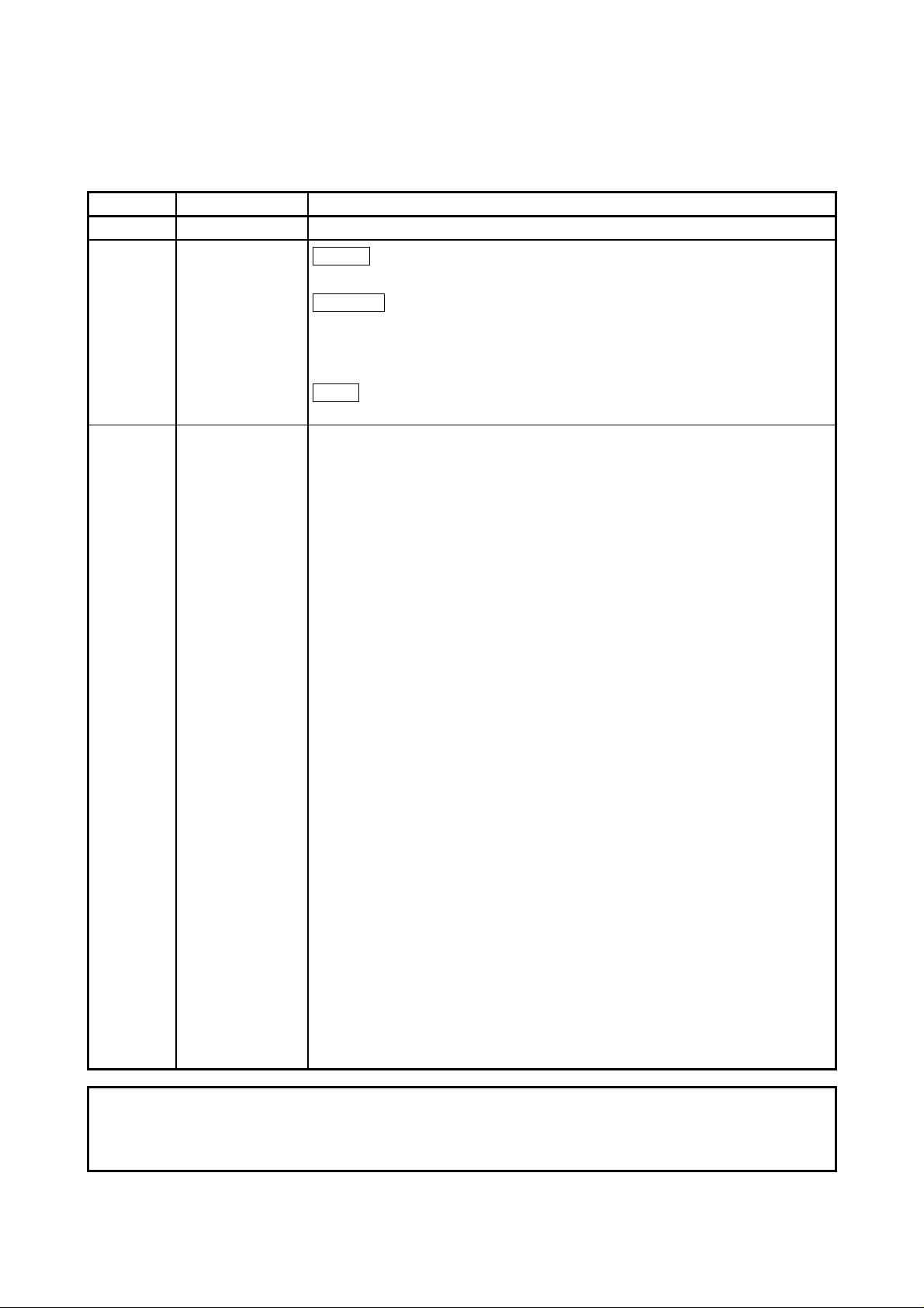
The following diagram outlines the peripheral devices and programs using a
positioning software package, data creation, and A173UHCPU/A172SHCPUN/
A171SHCPUN processing.
[Peripheral device] [Program, data] [A173UHCPU/A172SHCPUN/A171SHCPUN]
IBM PC
+
SW SRX-GSV PE,
SW RN-GSV PE
+
SW SRX-SV ,
SW RN-SV
Sequence program
Servo program or
motion program
Positioning
parameter
SCPU
Positioning
device
PCPU
Sequence control
Servo program or motion
program execution
JOG operation
For communication
between SCPU and PCPU
Positioning control
Home position return
Servo monitoring
1 − 1
Page 14
1. SPECIFICATIONS OF MOTION SYSTEM COMPONENTS
•
The sequence program written into the SCPU, the servo program or motion
program written into the PCPU, and the positioning parameters are created
after starting up corresponding positioning software package by the
peripheral device.
•
The peripheral device started up by the positioning software package can
monitor the positioning control conditions of A173UHCPU/A172SHCPUN/
A171SHCPUN, execute the servo program or motion program, and perform a
test such as JOG operation.
REMARKS
For information about a peripheral device and programming information for
producing a sequence program and a special function unit, refer to each
manual pertaining to the individual unit.
For information about creating motion programs, refer to the programming
manual of the operating system used. For information about the operation of
each peripheral software package, refer to each individual operating manuals.
In this manual, the following abbreviations are used.
Description Abbreviation
A173UHCPU/A172SHCPUN/ A171SHCPUN Module
MR-H-BN,MR-J2S-B,MR-J2-B servo amplifier MR-H-BN/MR-J2S-B/MR-J2-B
A172SENC manual pulse generator/synchronous encoder interface unit/module A172SENC
Fast serial communication betw een motion control ler and serv o ampl ifi er SSCNET
A173UHCPU/A172SHCPUN/
A171SHCPUN or CPU module
*1
*1 SSCNET: Servo System Controller NETwork
1 − 2
Page 15
1. SPECIFICATIONS OF MOTION SYSTEM COMPONENTS
1.2 Overall Configuration of Motion System
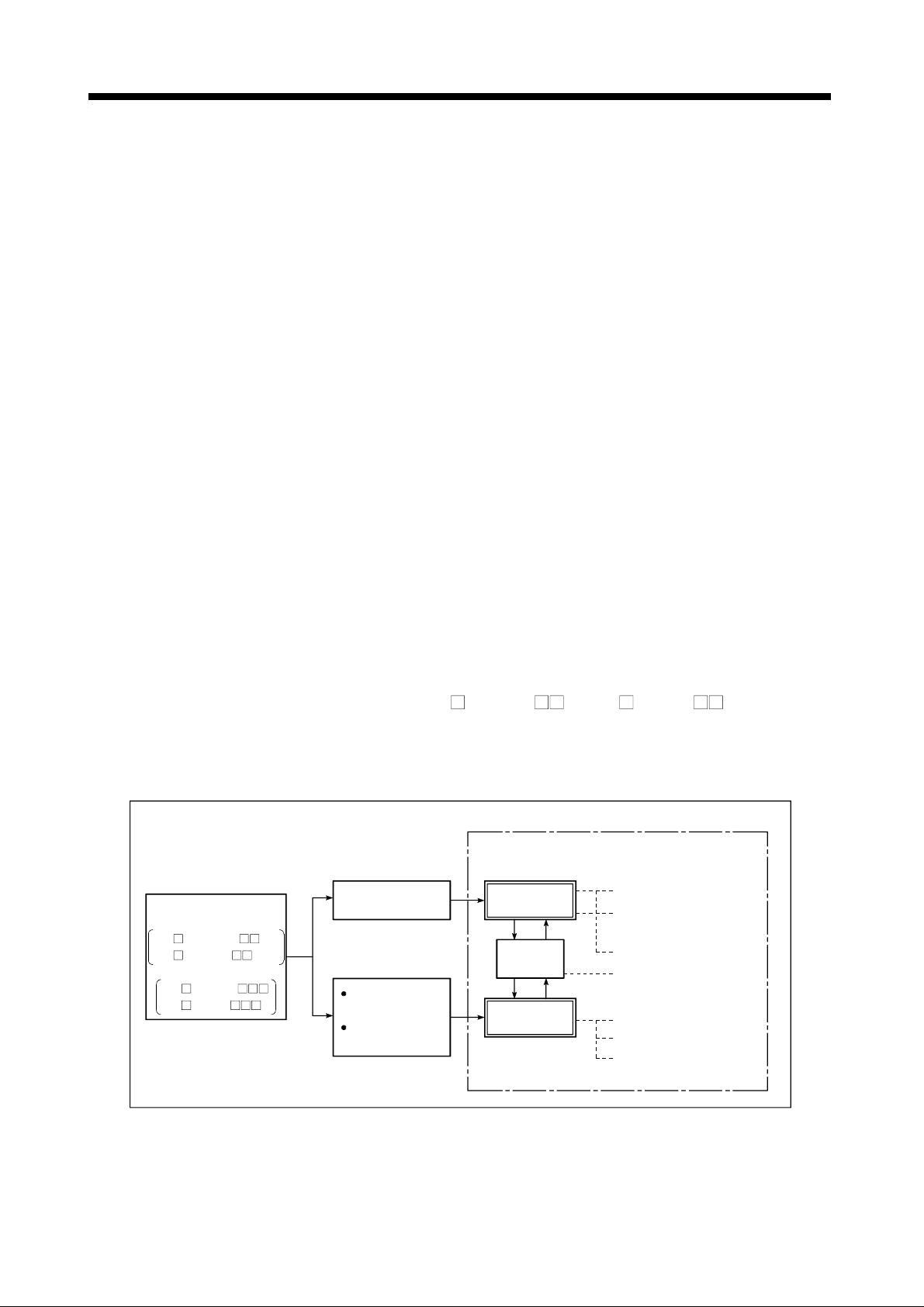
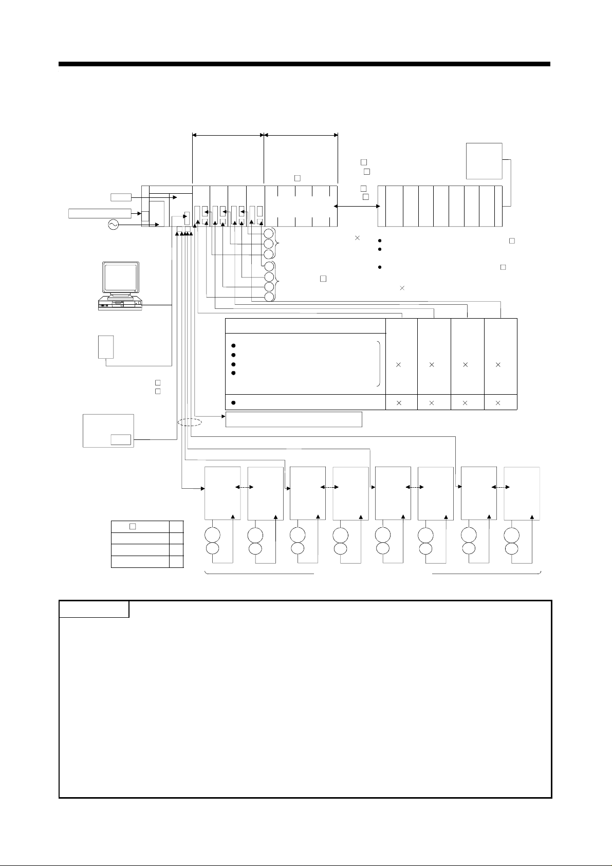
1.2.1 A172SHCPUN/A171SHCPUN System Overall Configuration
Manual pulse generator/
synchronous encoder
interface module
Battery
A6BAT
Emergency stop input
100/200VAC
IBM PC
(DOS)
Teaching unit
A31TU-E/A30TU-E
RS422
Communication cable
(A270CDCBL M/
A270BDCBL M)
IBM PC (DOS,Windows)
SSCNET2
SSC I/F card/board
(A30CD-PCF/A30BD-PCF)
Motion CPU
RS422
Motion slot Sequence module slot
A172
SENC
SSCNET cable
SSCNET1
*1
Limit switch
output mo dule
A1S
Y42
A1S input module or
special function module
Manual pulse generator 1
P
(MR-HDP01)
Serial absolute synchronous encoder cable
(MR-HSCBL M)
E
Serial absolute synchronous encoder 1
(MR-HENC)
External input signals
FLS upper stroke limit
RLS lower stroke limit
STOP signal
DOG/CHANGE near-zero point dog/
changeover between speed and position
TRA tracking
Electromagnetic brake command output
d1 d2 d3 dn
Extension cable
(A1SC B for
A1S6 B
and A168B)
(A1S NB
for A6 B)
Main base unit(A178B-S1/A17 B)
GOT
module
Power supply
Sequence extension base
Up to one extension base unit for A1S6 B
Up to one extension base unit for A168B
(GOT compatible)
Up to one extension base unit for A6 B
A171SHCPUN A172SHCPUN
4
1
8
1
*2
Termination
resistance
*1:No. of motion slots
A17 B 1
A178B-S1 2
M
E
M
E
M
E
M
E
*2:n:No. of control axes (max.)
A171SHCPU N 4
A172SHCPU N 8
MR-H-BN/MR-J2S-B/MR-J2-B model
Servo amplifier
SSCNET:Servo System Controller NETwork
POINTS
(1) When using the sequence extension base and bus connection type GOT, select the A168B as the
sequence extension base. When not using the sequence extension base, you can connect the bus
connection type GOT directly to the extension connector of the main base unit.
(2) When using a teaching unit A31TU-E with a dead-man switch, a dedicated connecting cable
A31TUCBL03M is required between the CPU unit and A31TU-E connector. If the A31TU-E is
connected directly to the RS422 connector of the CPU without using a dedicated cable, the
A31TU-E will not operate at all. After disconnecting the A31TU-E, attach a short-circuit connector
A31SHORTCON for A31TUCBL.
(3) In a motion module, a sequence A1S I/O modules can also be installed.
(4) Though the external input signals of A172SENC are reserved for eight axes, for A171SHCPUN,
set those for the first half four axes (PX0 to PX0F).
1 − 3
Page 16

1. SPECIFICATIONS OF MOTION SYSTEM COMPONENTS
CAUTION
Configure safety circuits external to the controller or servo amplifier if their abnormal operation
could cause axis motion in a direction other than the safe operating direction for the system.
Ensure that the characteristics of other components used in a system match those of the
controllers, servo amplifiers, and servo motors.
Set the parameters to values appropriate for the controllers, servo amplifiers, servo motors,
regenerative resistor types, and system application. The protective functions may not work if the
parameters are set incorrectly.
1 − 4
Page 17
1. SPECIFICATIONS OF MOTION SYSTEM COMPONENTS
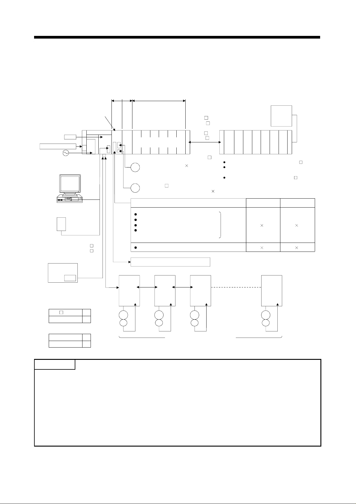
1.2.2 A173UHCPU System Overall Configuration
Battery
A6BAT
Emergency stop input
100/200VAC
IBM PC
(DOS)
Teaching unit
A31TU-E/A30TU-E
RS422
Communication cable
(A270CDCBL M/
A270BDCBL M)
IBM PC (DOS,Windows)
SSCNET4
SSC I/F card/board
(A30CD-PCF/A30BD-PCF)
A173UHCPU
RS422
*2
Motion slot Sequence module slot
Manual pulse
generator/
synchronous encoder
interface module
A172
SENC
*2
*1
Main base unit
(A178B-S3/
A178B-S2/
A178B-S1/
A17 B)
A172
A172
SENC
A172
SENC
SENC
A1S input module or
special function module
P
Manual pulse generator 3
P
(MR-HDP01)
P
Serial absolute synchronous
E
encoder cable
E
(MR-HSCBL M)
E
Serial absolute synchronous encoder 4
E
(MR-HENC)
External input signals
FLS upper stroke limit
RLS lower stroke limit
STOP signal
DOG/CHANGE near-zero point dog/
speed-position change
TRA tracking
Electromagnetic brake command output
SSCNET2
d1
*3
SSCNET cable
SSCNET3
d8
d9
Extension cable
(A1SC B for
A1S6 B
and A168B)
(A1S NB
for A6 B)
d16
GOT
module
Power supply
Sequence extension base
Up to one extension base unit for A1S6 B
Up to one extension base unit for A168B
(GOT compatible)
Up to one extension base unit for A6 B
8
1
SSCNET4
d17
8 8 8
1 1 1
d24
d25
d32
SSCNET1
*1:No. of motion slots
A17 B 1
A178B-S1 2
A178B-S2 4
M
E
M
E
M
E
M
E
M
E
M
E
M
E
M
E
A178B-S3 8
MR-H-BN/MR-J2S-B/MR-J2-B model
Servo amplifier, max. 32 axes
SSCNET:Servo System Controller NETwork
POINTS
(1) When using the sequence extension base and bus connection type GOT, select the A168B as the
sequence extension base. When not using the sequence extension base, you can connect the bus
connection type GOT directly to the extension connector of the main base unit.
(2) When using a teaching unit A31TU-E with a dead-man switch, a dedicated connecting cable
A31TUCBL03M is required between the CPU unit and A31TU-E connector. If the A31TU-E is
connected directly to the RS422 connector of the CPU without using a dedicated cable, the
A31TU-E will not operate at all. After disconnecting the A31TU-E, attach a short-circuit connector
A31SHORTCON for A31TUCBL.
(3) In a motion module, a sequence A1S I/O modules can also be installed.
*2 The A173UHCPU can use four channels of the SSCNET. When using the SSCNET card/board
(A30CD-PCF/A30BD-PCF), connect it to the SSCNET4 and the servo amplifiers to the SSCNET1
to 3.
In this case, up to 24 axes of servo amplifiers can be connected.
*3 TRA tracking enable can use any one point.
1 − 5
Page 18

1. SPECIFICATIONS OF MOTION SYSTEM COMPONENTS
CAUTION
Configure safety circuits external to the controller or servo amplifier if their abnormal operation
could cause axis motion in a direction other than the safe operating direction for the system.
Ensure that the characteristics of other components used in a system match those of the
controllers, servo amplifiers, and servo motors.
Set the parameters to values appropriate for the controllers, servo amplifiers, servo motors,
regenerative resistor types, and system application. The protective functions may not work if the
parameters are set incorrectly.
1 − 6
Page 19
1. SPECIFICATIONS OF MOTION SYSTEM COMPONENTS
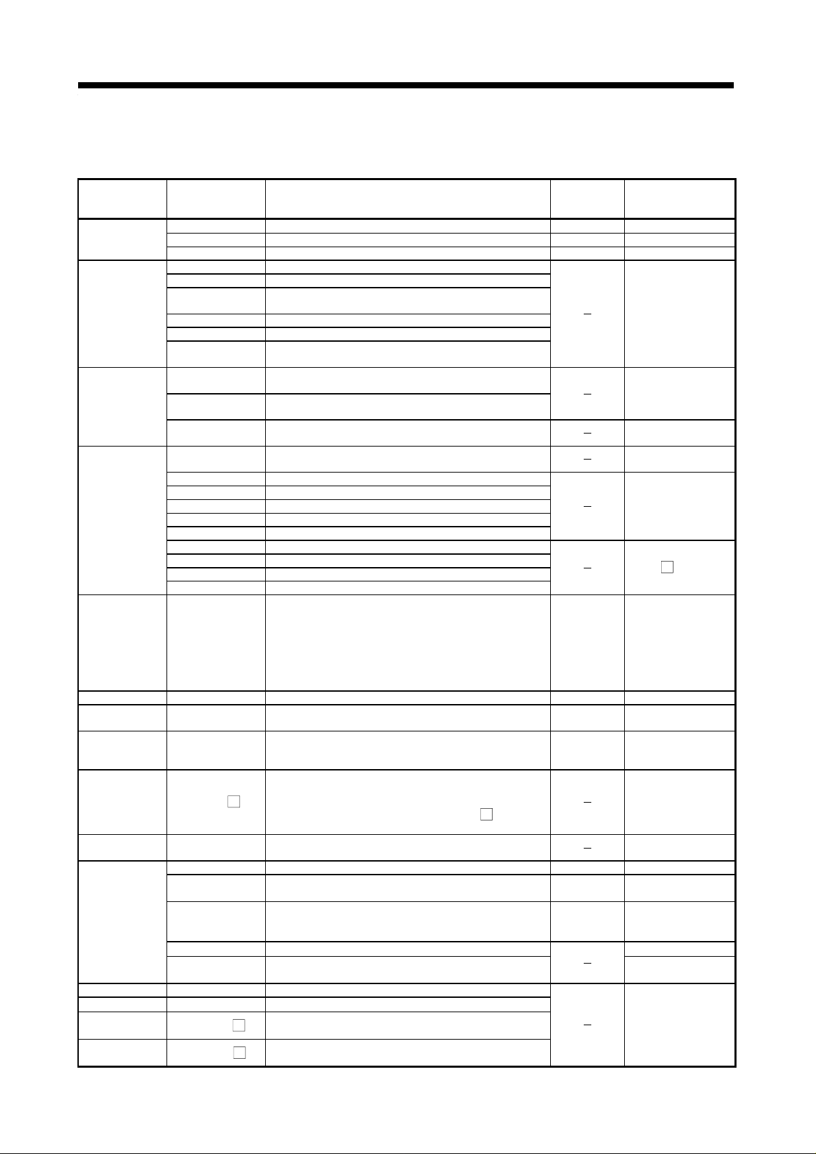
1.3 Equipment in System (1) Table of motion modules
Part Name Model Name Description
A173UHCPU(-S1) Max. 32 axes control 1.90
A172SHCPUN Max. 8 axes control 1.63CPU module
A171SHCPUN Max. 4 axes control 1.63
A172B One motion module slot and one sequence module slot
A175B One motion module slot and four sequence module slots
Main base unit
Sequence
extension base
unit
Extension cable
Manual pulse
generator
/synchronous
encoder
interface
module
Limit output unit A 1SY4 2 Transistor output 64 points, 12/24 VDC, 0.1A 0.93
Manual pulse
generator
Serial absolute
synchronous
encoder
Serial absolute
synchronous
encoder cable
Battery A6BAT
Teaching unit
SSC I/F board A30BD-PCF ISA bus loading type, 2 channels/board
SSC I/F card A30CD-PCF PCMCIA TYPE II, 1 channel/card
SSC I/F board
cable
SSC I/F card
cable
A178B
A178B-S1 Two motion module slots and six sequence module slots
A178B-S2 Four motio n module slots and four sequence module slots
A178B-S3
A1S65B
A1S68B
A168B
A1SC01B Flat cable of 55 mm (2.17 in) in length
A1SC03B Length 330 mm (13 in)
A1SC07B Length 700 mm (27 in)
A1SC12B Length 1200 mm (47 in)
A1SC30B Length 3000 mm (118 in)
A1SC60B Length 6000 mm (236 in)
A1SC05NB Length 450 mm (17 in) AnN extension base cables
A1SC07NB Length 700 mm (27 in) AnN extension base cables
A1SC30NB Length 3000 mm (118 in) AnN extension base cables
A1SC50NB Length 5000 mm (197 in) AnN extension base cables
A172SENC
MR-HDP01
MR-HENC
MR-HSCBL
A30TU-E For SV13, cable length 5 m (16.4 ft) 0.22
A31TU-E
A31TU-RE
A31TUCBL03M CPU module to A31TU-E connector cable of 3 m (9.84 ft.) For control panel
A31SHORTCON Short-circuit connector for A31TUCBL
A270BDCBL
A270CDCBL
One motion module slot and seven sequence module
slots
Eight motion module slots and zero sequence module
slots
Extension power and five slots for system up to one
extension stage
Extension power and eight slots for system up to one
extension stage
Extension power and eight slots for system up to one
extension stage
32 points I/O signals
(FLS, RLS, STOP, DOG/CHANGE×8)
Tracking input 1 point
Electromagnetic brake control output 1 point
Manual pulse generator interface 1 point
Synchronous encoder interface 1 point
4.5 VDC to 13.2 VDC 25 PLS/rev, 100 PLS/rev at
magnification of 4
Resolution: 16384 PLS/rev,
Permitted rotational speed: 4300r/min
Synchronous encoder and A172SENC connector cables:
2 m (6.56 ft.), 5 m (16.4 ft.), 10 m (32.8 ft.), 20 m (65.6
ft.), 30 m (98.4 ft.)
M
(Same cables as encoder cables for HA-LH
SF/RF/UF(2000r/min)series motors.)
For CPU module memory back-up
(Sequence program/servo program)
For SV13 with deadman switch, cable length 5 m (16.4
ft)
For SV51 with deadman switch, cable length 5 m (16.4
ft)
(Need A31TUCBL03M and A31SHORTCON.)
3 m (9.84 ft.), 5 m (16.4 ft.), 10 m (32.8 ft.) for
M
A30BD-PCF
3 m (9.84 ft.), 5 m (16.4 ft.), 10 m (32.8 ft.) for
M
A30CD-PCF
K, HC-
Current
Consumption
5 VDC (A)
0.42
0.06
0.15
0.22
0.22
1 − 7
Remarks
Sequence extension
connector as
accessory
Extension connector
as accessory
For extension to the
right side
For A6 B
When A31TU-E is
not connected
Page 20
1. SPECIFICATIONS OF MOTION SYSTEM COMPONENTS
y
(2) Table of servo amplifier modules
Part Name Model Name Description
50 W to 22 kW
30 kW to 55 kW
External regenerative resistor 10 W to 500 W
Regenerative power 600 W
External regenerative resistor 1300, 3900 W
For connection of CPU module and MR-H-BN, for connection of MR-H-BN and
MR-H-BN
0.5 m(1.64 ft), 1 m (3.28ft), 5 m (16.4 ft)
For connection of HA-LH
BN
M-H
2 m (16.4 ft), 5 m (16.4 ft), 10 m (32.8 ft), 20 m (65.6 ft), 30 m (98.4 ft)
For
HA-LH
Amplifier side connector and encoder side connector set
50 W to 7 kW, three-phase 200 to 230 VAC or single-phase 230 VAC
50 W to 400 W, single-phase 100 to 120 VAC
For connection of CPU module and MR-J2S-B/MR-J2-B, for connection of MR-HBN and MR-J2S-B/MR-J2-B
M-A
0.5 m(1.64 ft), 1 m (3.28ft), 5 m (16.4 ft)
For connection of MR-J2S-B/MR-J2-B and MR-J2S-B/MR-J2-B
M
0.5 m(1.64 ft), 1 m (3.28ft), 5 m (16.4 ft)
Standard
M-L
cable
M-H
Long flexing
life cable
M-H
Standard
M-L
cable
Long flexing
M-H
life cable
For HC-SF/RF/UF (2000r/min), HC-SFS/RFS/UFS (2000r/min) series motors
Amplifier side connector and encoder side connector set
For HC-MF/UF (3000r/min), HA-FF, HC-MFS/KFS/UFS (3000r/min) series motors
Amplifier side connector and encoder side connector set
K, HC-SF/RF/UF (2000r/min) series motors
For connection of HC-SFS/RFS/UFS (2000r/min) series motor and
MR-J2S-B, and for connection of HC-SF/RF/UF (2000r/min) series
motor and MR-J2-B
2 m (6.56 ft), 5 m (16.4 ft), 10 m (32.8 ft), 20 m (65.6 ft),
30 m (98.4 ft)
For connection of HC-MFS/KFS/UFS (3000r/min) series motor and
MR-J2S-B, and for connection of HC-MF/UF (3000r/min), HA-FF
series motor and MR-J2-B
2 m (6.56 ft), 5 m (16.4 ft), 10 m (32.8 ft), 20 m (65.6 ft),
30 m (98.4 ft)
K, HC-SF/RF/UF (2000r/min) series motor and MR-H-
MR-H-BN
series
MR-J2S-B
series
MR-J2-B
series
Equipment
common to
MR-J2S-B
and
MR-J2-B
series
Servo amplifier
Battery MR-BAT Backup for absolute position detection
Termination
connector
Regenerative
resistor
SSCNET cable MR-HBUS
Encoder cable
*2
Encoder
connector set
Servo amplifier
Servo amplifier MR-J2Battery MR-BAT Backup for absolute position detection
Termination
connector
SSCNET cable
Encoder cable
*2
Encoder
connector set
MR-H BN
MR-H
KBN
MR-TM Fitted to the last amplifier of SSCNET
MR-PB
MR-H
KB
Standard accessor
MR-PB -4
FR-BU Brake unit 15/30/55K
FR-RC Power return converter 15/30/55K
M
MR-HSCBL M
MR-EN1CBL
MR-JSCNS
MR-EN1CNS
MR-J2S- B
MR-J2S-
MR-A-TM Fitted to the last amplifier of SSCNET
MR-J2HBUS
MR-J2HBUS
MR-JHSCBL
MR-JHSCBL
MR-ENCBL
MR-JCCBL
MR-JCCBL
MR-J2CNS
MR-ENCNS
MR-J2CNM
*1: 5kW and 7kW are scheduled for release.
*2: Long distance cable or cable without connector (cable only) is also available.
Avoid using a short cable as it will cause a position shift or the like.
*1
B1
B 50 W to 3.5 kW
1 − 8
Page 21
1. SPECIFICATIONS OF MOTION SYSTEM COMPONENTS
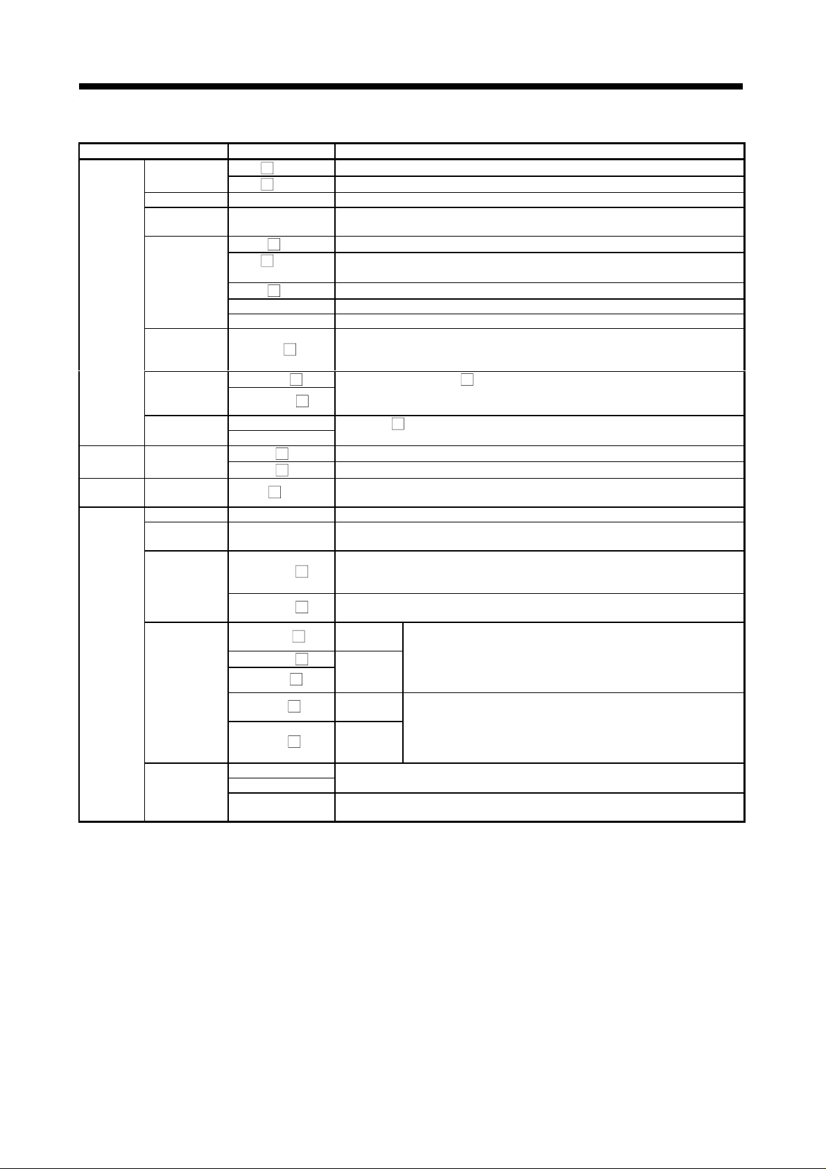
(3) Table of software package
(a) Motion function
Peripheral Software Package Main OS Software Package Model Name
Use
For conveyor
assembly
(SV13)
For motion
SFCcompatible
conveyor
assembly
(SV13)
For automatic
machinery
(SV22)
For motion
SFCcompatible
automatic
machinery
(SV22)
For machine
tool peripheral
(SV43)
For dedicated
robot (SV51)
Peripheral
Devices
Japanese SW2SRX-GSV13P From 0AC on 00T or later
DOS
English SW2SRX-GSV13PE From 00J on 00F or later
IBM PC/AT
IBM PC/AT
IBM PC/AT
IBM PC/AT
IBM PC/AT DOS Japanese SW2SRX-GSV43P From 00T on 00J or later
IBM PC/AT DOS Japanese SW2SRX-GSV51P
Japanese SW3RNC-GSV From 00F on 00E or later
NT/
98
English SW3RNC-GSVE
Japanese SW3RNC-GSV From 00F on
NT/
98
English SW3RNC-GSVE
Japanese
DOS
English
Japanese SW3RNC-GSV From 00F on 00E or later
NT/
98
English SW3RNC-GSVE
Japanese SW3RNC-GSV From 00F on
NT/
98
English SW3RNC-GSVE
Model Name
SW2SRX-GSV22P From 0AC on 00T or later
SW0SRX-CAMP From 00B on 00B or later
SW2SRX-GSV22PE From 00J on 00F or later
SW0IX-CAMPE
Applicable version
For
A173UH
Without
restriction
Without
restriction
Without
restriction
Without
restriction
Without
restriction
For
A172SH/
A171SH
Without
restriction
Without
restriction
Without
restriction
Without
restriction
Without
restriction
Without
restriction
Without
restriction
00E or later
For
A173UH
SW2SRXSV13B
SW2SRXSV13B
SW3RNSV13B
SW2SRXSV22A
SW3RNSV22A
SW2SRXSV43A
A172SH
SW0SRXSV13D
SW2SRXSV13D
SW3RNSV13D
SW0SRXSV22C
SW3RNSV22C
SW0SRXSV43C
SW0SRXSV51D
For
For
A171SH
SW0SRXSV13G
SW0SRXSV13G
SW0SRXSV22F
SW0SRXSV43F
SW0SRXSV51G
Teaching
function
Yes
No
No
Yes
1 − 9
Page 22
1. SPECIFICATIONS OF MOTION SYSTEM COMPONENTS
1.4 General Specifications
Table 1.1 Generation Specifications
Item Specification
Operating ambient
temperature
Storage ambient
temperature
Operating ambient
humidity
Storage ambient
humidity
Frequency Acceleration Amplitude
Vibration resistance
Shock resistance Conforms to JIS C 0912 (98m/s2 (10g), 3 directions, 3 times)*
Noise resistance
Withstand voltage 2830V A C rms / 3 cycles across all i nputs/ LG and all out puts/F G (alt itude 2000m (6557. 38f t. ))
Insulation resistance 5M
Ground Class 3 grounding. Connect to enclosure when grounding is impossible.
Operating environment No corrosive gas, low dust
Cooling method Natural cooling.
Conforms to JIS C
2
0911*
(1) Noise voltage: 1500Vpp, noise amplitude: 1
(2) Noise voltage : IEC801-4, 2 kV
or more by 500VDC insulation resistance tester across all inputs/LG and all outputs/FG
10 to 55Hz
55 to 150Hz 9.8m/s
10% to 90%RH, no condensation
10% to 90%RH, no condensation
0 to 55°C
-20 to 75°C
Number of Sweeps
0.075mm
(0.003 in)
2
2
µ
s, noise frequency: 25 to 60 Hz, with a noise simulator
(1 octave/minute)*
10
1
REMARKS
*1 An “octave” refers to an increase or decrease in frequency by a factor of
two. For example, the following are all octaves: 10 Hz to 20 Hz, 20 Hz to
40 Hz, 40 Hz to 20 Hz, and 20 Hz to 10 Hz.
Refer to “CHAPTER 2 DESIGN” for the installation environment and
mounting instructio ns.
*2 JIS: Japan Industrial Standards
WARNING
Class 3 grounding should be used. The motion controller should not share a common ground with
any other equipment. The ground terminal is located on the motion controller module terminal
block. (See Section 1.5.2.)
CAUTION
The motion controller must be stored and operated under the conditions listed in the table of
specifications above.
Disconnect the power cables from the motion controller if it is to remain unused for a long period
of time.
Insert a controller or servo amplifier into the static-proof vinyl bag for storage.
Consult the system service or service station before storing equipment for a long period of time.
1 − 10
Page 23
1. SPECIFICATIONS OF MOTION SYSTEM COMPONENTS
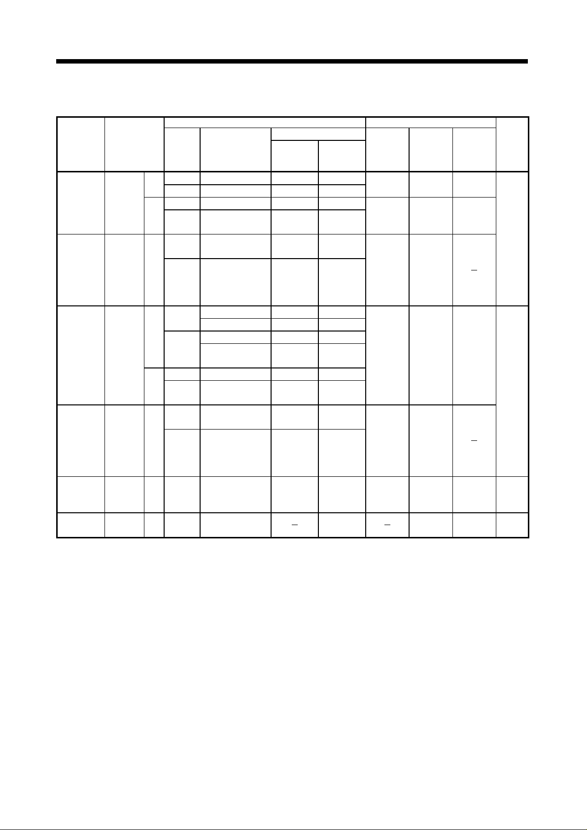
1.5 Specifications and Settings of Components
1.5.1 A173UHCPU/A172SHCPUN/A171SHCPUN (1) Basic specifications of A173UHCPU, A172SHCPUN and A171SHCPUN
Item A173UHCPU(-S1) A172SHCPUN A171SHCPUN
No. of control axes 32-axes 8-axes 4-axes
SV13
Motion
PC
System
configuration
Compatibility
Outside dimensions 130 113.3 93.6 (5.12 4.46 3.69) unit = mm (inch)
Weight (kg (lb)) 0.85 (1.87)
Computing
frequency
Sequencer CPU Equivalent to A3UCPU
Processing speed
(
s) (Sequence
instruction)
No. of I/O points 8192 points 2048 points
No. of real I/O points *
Memory capacity (built-in RAM)
Program capacity
(Main sequence)
No. of file register (R) Max. 8192 registers
2
block *
No. of sequencer extension
base units
Pulser synchronous encoder
interface unit
No. of SSCNET I/F 4CH.
Teaching unit (OS
with teaching
function)
Sequence program, parameter
Servo program
Mechanism program (SV22)
Parameter
System setting Must be set anew.
SV22
Direct
method
Refresh
method
1
Standard
-S1
Standard Max. 10 blocksNo. of extension file register
-S1 Max. 46 block s
(Corresponding to external signal input
A30TU-E
A31TU-E
After starting A173UHCPU and reading
a file, those created by A273UHCPU
(32-axes) can be used as it is.
3.5 ms/1 to 20 axes
7.1 ms/21 to 32 axes
3.5 ms/1 to 12 axes
7.1 ms/13 to 24 axes
14.2 ms/25 to 32 axes
0.15
s/step 0.25 s/step
2048 points 1024 points 512 points
192k bytes (Equivalent to
A3NMCA-24)
768k bytes (Equivalent to
A3AMCA-96)
Max. 30k steps Max. 30k steps Max. 14k steps
A172SENC
32-axes)
4
(With dead-man switch)
3.5 ms/1 to 8 axes 3.5 ms/1 to 4 axes
Equivalent to
reinforced I/O
memory of
A2SHCPU
0.25 to 1.9 s/step
192k bytes
(Equivalent to
A3NMCA-24)
Max. 10 blocks Ma x. 2 blocks
Max. one
A172SENC 1
(Corresponding to external signal input
8-axes)
2CH.
SSCNET1..... For connection of servo
SSCNET2..... For personal computer link
After starting A172SH/A171SH and
reading a file, those created by
A171SCPU can be used as it is.
By making sure of system setting screen
after being started up by A172SH/A171SH
and reading a file, changeover below is
carried out:
A171SCPU
A171SENC
now the system is ready for operation.
amplifier
dedicated
A172SH/A171SHCPUN
A172SENC
Equivalent to
A2SHCPU
64k bytes
(Equivalent to
A3NMCA-8)
*1 The real I/O points can be used within the range of one extension base.
*2 No. of extension file register blocks varies depending on the setting of program capacity, No. of file
registers, and No. of comments.
1 − 11
Page 24

1. SPECIFICATIONS OF MOTION SYSTEM COMPONENTS
(2) Functions and performance specifications of PCPU
The performance specifications and functions of the PCPU depend on the
motion function OS model installed in the CPU module.
Refer to the programming manual of the motion functions installed in the CPU
module.
1 − 12
Page 25
1. SPECIFICATIONS OF MOTION SYSTEM COMPONENTS
(3) SCPU performance specifications and functions
(a) SCPU performance specifications
As the SCPU performance specifications differ according to the operating
system used, refer to the appropriate OS Programming Manual for details.
Table 1.2 Table of SCPU Performance Specifications
Item A173UHCPU(-S1) A172SHCPUN A171SHCPUN
Control method Stored programs repe at ed op era ti on
I/O control method Refresh method Refresh method/direct method (selectable)
Programming language
Sequence instructions 22 26
Number of instructions
Processing speed ( s)
(sequence instructions)
No. of I/O points 8192 points (X/Y0 to 1FF) 2048 points (X/Y0 to X/Y7FF)
No. of real I/O points *
Watchdog timer (WDT) 200 ms fixed 10 to 2000 ms
Memory capacity (internal RAM)
No. of internal relays (M) *
No. of latch relays (L) 1048 points (L1000 to L2047)
No. of step relays (S) 0 point (none at initial status)
No. of link relays (B) 8192 points (B0 to B1FFF) 1024 points (B0 to B3FF)
Timers (T)
Device
Counters (C)
No. of data registers (D) *
No. of link registers (W) 8192 points (W0 to W1FFF) 1024 points (W0 to W3FF)
No. of annunciators (F) 2048 points (F0 to F2047) 256 points (F0 to F255)
No. of file registers (R) Max. 8192 points (R0 to R8191) (set with parameters)
No. of accumulators (A) 2 points (A0, A1)
No. of index registers (V, Z)
No. of pointers (P) 256 points (P0 to P255)
No. of interrupt pointers (I) 32 points (I0 to I31)
No. of special-function rela ys( M) 256 points (M9000 to M9255)
No. of special-function registers (D)
Basic instructions 252 131
Special instructions 204 106
Motion dedicated instruc ti on s 4 4
Direct method 0.25 to 1.9 s/step
Refresh method 0.15
5
Standard
-S1
Main sequence program Max. 30 k steps Max. 14k steps
Sub-sequence program Max. 30k steps None NoneProgram capacity
Micro computer program None Max. 58k bytes Max. 26k bytes
1
Points 256 points
Specifications
Points 256 points
Specifications
1
8192 points (D0 to D8191) 1024 points (D0 to D1024)
(Relay symbol language, logic symbol language, MELSAP-II (SFC))
s/step 0.25 s/step
2048 points (X/Y0 to 7FF)
192k bytes
(Equivalent to
A3NMCA-24)
768k bytes
(Equivalent to
A3AMCA-96)
7144 points (M0 to M999,
M2048 to M8191)
100 ms timer 0.1 to 3276.7s T0 to T199
10 ms timer 0.01 to 327.67s T200 to T255
100ms retentive timer 0.1 to 3276.7s No initial value
Normal counter 1 to 32767 C0 to C255
Interrupt program counter 1 to 32767
14 points
(V, V
to V6, Z, Z1 to Z6)
1
Sequence control dedicated language
1024 points (X/Y0 to
X/Y3FF)
192k bytes 64k bytes
1000 points (M0 to M999)
Time setting Device
Set with parameters
Setting range Device
Set with parameters
2 points (V, Z)
256 points (D9000 to D9255)
512 points (X/Y0 to X/Y1FF)
C224 to C255
(No initial value)
3
*
4
*
1 − 13
Page 26

1. SPECIFICATIONS OF MOTION SYSTEM COMPONENTS
Table 4.1 Table of SCPU Performance Specifications (Continued)
Item A173UHCPU (-S1) A172SHCPUN A171SHCPUN
Standard
No. of extension file register block
-S1
No. of comments Max. 4032 points (64k by tes), 1 point = 16 bytes (set in 64-point unit)
No. of extension comments *
Self-diagnosis function Watchdog error monitoring, memory/CPU/input output/battery, etc. error detection
Operating mode on error Select stop/continue
Output mode selection when switching from STOP to RUN
Clock function Year, month, day, hour, minute, day of the week (leap year automatic distinction)
*1 Range of positioning dedicated devices differs depending on the OS. Refer to the Programming Manual of each OS.
When shared between M, L and S, the total number of devices points is 8192 for the A173UHCPU or 2048 for the A172SHCPUN/A171SHCPUN.
*2 Extension comments are not stored into the internal memory of the CPU.
*3 For the A173UHCPU, set the times of the extension timers (T256 to T2047) using the word devices (D, W, R).
*4 For the A173UHCPU, set the count values of the extension counters (C256 to C1023) using the word devices (D, W, R).
*5 The real I/O points can be used within the range of one extension base.
*6 SW0GHP-UTLP-FN1 is necessary for using A6GPP and A6PHP.
2
Max. 10 blocks
(set by memory
capacity)
Max. 46 blocks
(set by memory
capacity)
Max. 3968 points (63k bytes), 1 point = 16 bytes (set in 64-point unit)
Select re-output operation status before STOP (default) or output after operation
Max. 10 blocks
(set by memory capacity)
execution.
*6
Max. 3 blocks
(set by memory capacity)
*6
1 − 14
Page 27

1. SPECIFICATIONS OF MOTION SYSTEM COMPONENTS
(b) SCPU functions
Refer to the A2SHCPU user's manual for details of the SCPU functions of
A171SHCPUN/A172SHCPUN and A3UCPU user’s manual for details of
the SCPU functions of A173UHCPU.
Table 1.3 Table of SCPU Functions
Function Description
!
Sets a constant time for one scan of a sequence program which is independent of the sequence
Constant scan
Latch (hold on
power interruption)
Remote
RUN/STOP
PAUSE
Status latch
Sampling trace
Off-line switch
Error indicator
order or priority
Clock
program scan.
!
Set the constant scan time between 10 ms and 2000 ms.
!
The contents of devices set as latch devices are retained when a reset or a power interruption
over 20 ms occurs if the power is turned off.
!
Devices L, B, T, C, D, W can be set as latch devices.
!
Conducts remote RUN/STOP sequence control from external inputs or peripheral devices when
the RUN/STOP switch is set to RUN.
!
Stops the operation and holds the output (Y) ON/OFF status.
!
The PAUSE status can be set by two method:
!
With the remote PAUSE contacts
!
From a peripheral device
!
The contents of all devices are written to the CPU module status latch area when the status
latch conditions are met.
!
The contents of the devices stored in the status latch area can be monitored from a peripheral
device.
!
The operating status of the designated device is sampled at the set interval, and the results are
stored in the CPU module sampling trace area.
!
Data stored in the sampling trace area can be monitored from a peripheral device.
!
Separates the devices (Y, M, L, S, F, B) used by the OUT instruction from the sequence
program operations.
!
Sets order in which the indicators light and go out when an error occurs.
!
Executes the CPU module internal clock operations .
!
Clock data is: year, month, day, hour, minute, second, day of week.
!
The clock data can be read to D9025 to D9028.
1 − 15
Page 28
1. SPECIFICATIONS OF MOTION SYSTEM COMPONENTS
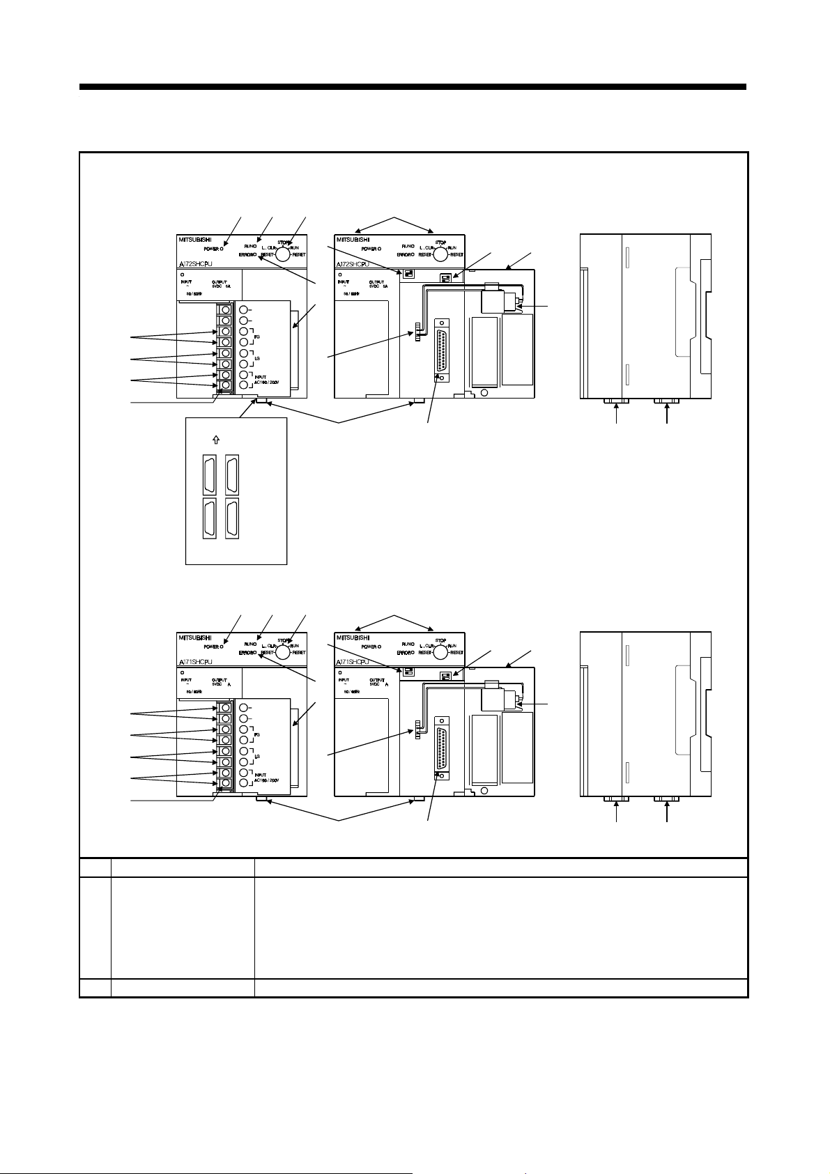
(4) Names of A173UHCPU/A172SHCPUN/A171SHCPUN Parts
A173UHCPU/A172SHCPUN
3)
1)2)
13)
6)
7)
8)
9)
A171SHCPUN
5)
6)
7)
8)
9)
N
100 240VAC
105VA
NC
NC
[A173UHCPU]
FRONT
SSCNET
4 1
3 2
1:SSCNET1 2:SSCNET2
3:SSCNET3 4:SSCNET4
N
100 240VAC
3
105VA
24VDC 0.6A
+24V
24G
15)
17)
1)2) 3)
15)
17)
4)
100 240VAC
10)
18), 19)
4)
100 240VAC
10)
16)
N
105VA
12)
14)
11) 19)
18)
13)
12)
N
3
105VA
24VDC 0.6A
16)
14)
18), 19)
11) 19)
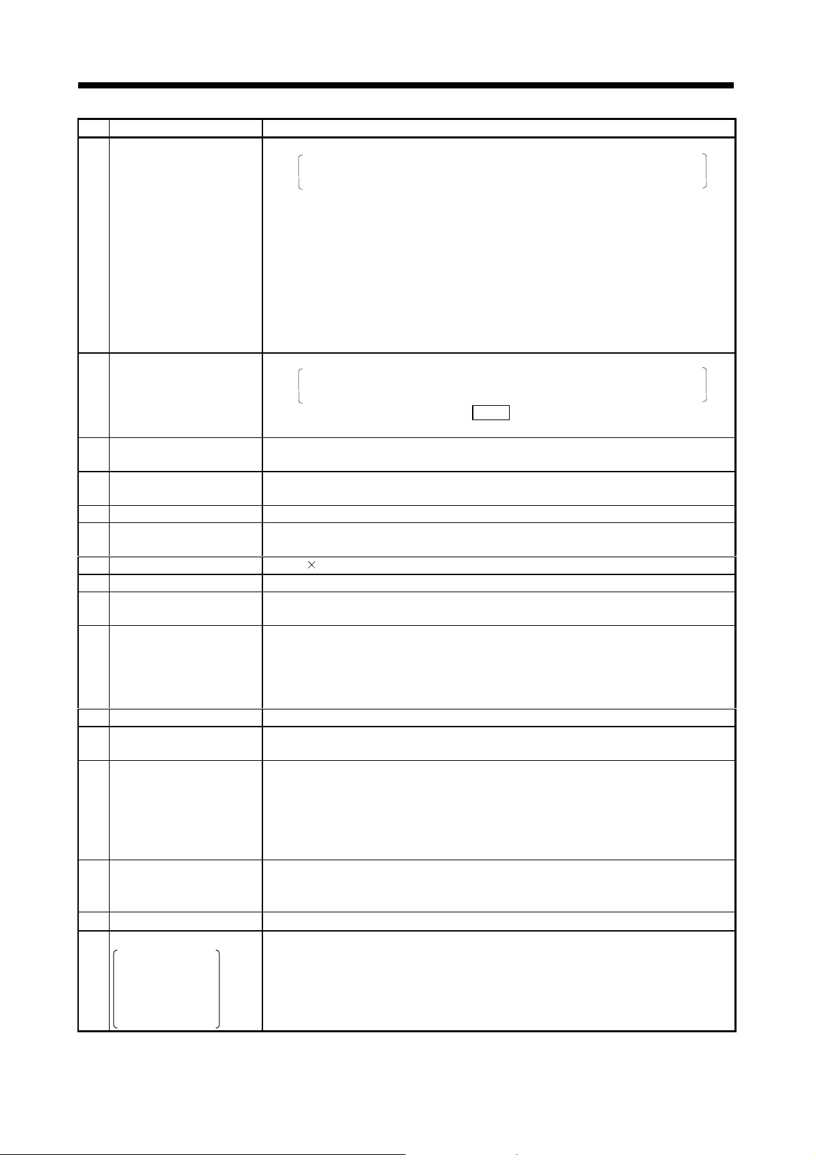
No. Name Application
!
RUN/STOP: Starts or stops operation of a sequence program.
!
RESET: Resets the hardware.
1) RUN/STOP key switch
!
LATCH CLEAR (L. CLR): Clears the latch area data set with the parameters
Applies a reset after an operation error occurs and initializes the operations.
(to OFF or 0).
(LATCH CLEAR also clears data outside the latch area.)
2) POWER indicator
!
Display indicator for 5 VDC power supply.
1 − 16
18)
Page 29
1. SPECIFICATIONS OF MOTION SYSTEM COMPONENTS
No. Name Applications
!
Lit: Sequence program operating with RUN/STOP key switch set to RUN.
The indicator remains lit if an operation error occurs in the sequence
program (Refer to section 5.4.1 (10)).
!
Not lit: The RUN indicator is not lit in the following cases:
!
No 100/200 VAC power supplied to the CPU module.
!
RUN/STOP key switch is set to STOP.
!
3) RUN i ndicator
4) ERROR indicator
24 VDC, 24 GDC
5)
terminals
6) FG terminal
7) LG terminal
Power supply input
8)
terminals
9) Terminal screws
10) Terminal cover
11) RS-422 connector
12) Covers
13) Module fixing screws
14) Battery
15) DIP switch 1
16) DIP switch 402
17) Battery connector
Motion network connector
SSCNET1 to 2
(A172SHCPUN/
18)
A171SHCPUN)
SSCNET1 to 4
(A173UHCPU)
!
Flashing: The RUN indicator flashes in the following cases:
!
Lit: Self-diagnosis function detected an error.
!
Not lit: Normal, or error detected by
!
Flashing: Sequence program annunciator (F) is on.
!
Internally supplies output modules which require 24 VDC (supplied through external
wiring). (A171SHCPUN only)
!
A grounding terminal connected with the shielding pattern on the printed circuit
board.
!
Ground for power supply filter, with 1/2 the electrical potential of the input voltage.
!
Connect the 100 VAC or 200 VAC power supply to the power supply input
terminals.
!
M3.5 7
!
A cover to protect the terminal block.
!
Connector to read, write, monitor, or test main programs with a peripheral device.
!
Covered by a cover when not connected to a peripheral device.
!
Open the protective cover for the printed circuit board, RS-422 connector, or
battery to carry out the following operations:
!
!
!
!
Screws to fix the module to the base unit.
!
Back-up battery for programs, devices in the latch range, and file registers.
(See Section 1.5.7 for the battery mounting procedure.)
!
Installation switch
This switch is used to change the installed CPU modu le opera t ing syst em w ith a
peripheral device.
(See Section 1.5.1 (5) for details about the switch settings.)
ON : Turn ON to install an operating system.
OFF : Turn OFF to enable CPU operation when OS installation is complete.
!
This switch selects the I/O control method and enables or disables memory
protection.
(See Section 1.5.1 (5) for details about the switch settings.)
!
A connector for connecting the battery unit
!
Connectors to HR-H-BN/MR-J2S-B/MR-J2-B.
A remote STOP is applied.
!
A remote PAUSE is applied.
!
Self-diagnosis function detected an error which stops sequence
program
operation.
!
A latch clear operation is conducted.
However, the indicator does not light if it is set not to light for the error
detected in the order of priority settings.
CHK
instruction.
Set DIP switches.
Connect the battery connectors.
Replace the battery.
1 − 17
Page 30

1. SPECIFICATIONS OF MOTION SYSTEM COMPONENTS
No. Name Applications
Personal computer link
SSC connector
SSCNET2
(A172SHCPUN/
19)
A171SHCPUN)
SSCNET4
(A173UHCPU)
!
A connector for linking a personal computer and personal computer link SSC.
When using the A172SHCPUN/A171SHCPUN, connect the servo amplifier or
personal computer to SSCNET2, or when using the A173UHCPU, connect it to
SSCNET4.
1 − 18
Page 31

1. SPECIFICATIONS OF MOTION SYSTEM COMPONENTS
(5) Switch settings
SW1
ON OFF
A17 SHCPUN
12
Operation mode setting
ON : Installation
OFF: Ordinary operation
Not used
SW402
ON OFF
4
32
1
* SW402-2 is invalid for A171SHCPUN.
* Memory allocation varies depending on the PC memory capacity
setting.
SW402
ON OFF
4
32
1
* Memory allocation varies depending on the PC memory capacity
setting.
For A172SHCPUN/A171SHCPUN
Not used
I/O control method setting
ON : Direct m ethod f or inputs and outputs
OFF: Refresh method for inputs and outputs
SCPU built-in RAM memory protect range setting
21
Less than a range from 64k to 256k bytes
Less than a range from 0k to 64k bytes
ON : Memory protect ON
OFF: Memory protect OFF
For A173UHCPU
SCPU built-in RAM memory protect range setting
43
More than 144k bytes
Less than a range from 64k to 144k bytes
21
Less than a range from 32k to 64k bytes
Less than a range from 0k to 32k bytes
ON : Memory protect ON
OFF: Memory protect OFF
1 − 19
Page 32

1. SPECIFICATIONS OF MOTION SYSTEM COMPONENTS
CAUTION
Switch SW1-2 is for use by the manufacturer only.
Leave this switch set OFF.
Operation cannot be guaranteed if this switch is set to ON.
POINTS
(1) Turn off the power supply before setting the install switch.
(2) After using this switch, check the switch status before turning on the power supply.
(3) The switch settings shipped from the factory are as shown above. The switch settings are
indicated by a mark (
(4) Whenever the switch settings are changed, be sure to reset the key of the CPU once or turn on the
power again.
(5) Turn off the power before setting the I/O control changeover switch.
(6) After using this switch, check the switch status before turning on the power supply.
(7) A BIN value corresponding to the selected I/O control method is input in special-function register
D9014 and can be monitored from a peripheral device. (A172SHCPUN/A171SHCPUN)
!
Direct method for inputs and outputs.........0
!
Refresh method for inputs and outputs .....3
(8) When executing the sampling trace and/or the status latch, do not protect the memory. If the
memory is protected, the result of execution cannot be stored in the memory.
).
1 − 20
Page 33

1. SPECIFICATIONS OF MOTION SYSTEM COMPONENTS
(6) Functions and performance specificotions of
A173UHCPU/A172SHCPUN/A171SHCPUN internal power supply.
Table 1.4 Internal Power Supply Specifications
Item Specifications
Model name A173UHCPU/A172SHCPUN A171SHCPUN
Input power supply
Input frequency 50/60 Hz 5 %
Max. apparent input power 105VA
Rush current 20A 8ms max.
Rated output current
Overcurrent protection
Overvoltage protection
Efficiency 65% min.
Power indicator LED indicator (Lit at 5VDC output)
Terminal screw size M3.5 7
Applicable power cable size 0.75 to 2mm
Applicable solderless terminal RAV 1.25-3.5 RAV 2-3.5
Applicable tightening torque 59 to 88 N⋅cm
Permissible instantaneous power interruption
time
5VDC 5A 3A
24VDC
5VDC 5.5 A min. 3.3 A min.
1
*
24VDC 0.66 A min.
5VDC 5.5 to 6.5 V
2
*
24VDC
10% 0.6A
100 to 240 VAC
(85 to 264 VAC)
20ms max.
+10%
-15%
2
POINTS
*1: Overcurrent protection
When current in excess of the specifications flows through the 5 VDC or
24 VDC circuits, the overcurrent protection device breaks the circuit and
stops the system.
A drop in voltage will extinguish or dim the CPU module indicator
“POWER” display.
After overcurrent protection operates, start up the system after
eliminating the cause, such as insufficient current capacity or short
circuit.
The system initial start commences when the current returns to the
normal level.
*2: Overvoltage protection
When an overvoltage of 5.5 V to 6.5 V is applied to a 5 VDC circuit, the
overvoltage protection device breaks the circuit and stops the system.
The CPU module indicator goes out.
To restart the system, switch the input power supply off, and then turn it
back on. The system initial start commences.
If the system does not start up and the indicator “POWER” display
remains off, the CPU module must be changed.
1 − 21
Page 34

1. SPECIFICATIONS OF MOTION SYSTEM COMPONENTS
(
)
(7) Information control processing making use of personal computer
By connecting a personal computer to the SSCNET, you can add to the motion
system the digital oscilloscope functions used for monitoring the equipment
status and for checking the operation, tuning and timing of the equipment and
the user-developed software functions (e.g. machining/assembling recipe
function and data supervising collection function).
Refer to the manual of the corresponding software package.
CPU module
Panel computer, etc.
SSCNET connector
*
Communication cable
(A270CDCBL M/A270BDCBL M)
SSCNET cable
SSC I/F card/board
A30CD-PCF/A30BD-PCF
* : Connect to SSCNET2 for the A171SHCPUN/A172SHCPUN or to
SSCNET4 for the A173UHCPU.
(8) MELSECNET(II)/10 system
The motion system can use the MELSECNET(II)/10 system. The usable
MELSECNET system depends on the CPU module. (See the following table.)
Load the module given in the following table into the PC slot to configure a data link
system.
MELSECNET
System
MELSECNET (II)
MELSECNET/10 Usable (local station only) Usable
A172SHCPUN/A171SHCPUN A173UHCPU Module
Usable(MELSECNET mode or
MELSECNET II mixed mode
only)
Usable A1SJ71AP21/R21
A1SJ71LP21/BR11
In the MELSECNET(II) data link system, the motion CPU module can be used
as the master or local station in each layer. When it is used as the master
station in layer 3 (local station in layer 2), up to two data link modules
(A1SJAP21/R21) m a y be used.
In the MELSECNET/10 network system, the motion CPU module can be used
as the control or normal station. Up to four network modules
(A1SJ71LP21/BR11) m a y be loaded to achiev e separ ate net wor k
configurations.
Refer to the following manuals when using the MELSECNET(II) data link system
and MELSECNET/10 network system.
•
MELSECNET(II), MELSECNET/B data link system reference manual
•
MELSECNET/10 data link system reference manual (Inter-PC network
manual)
1 − 22
Page 35

1. SPECIFICATIONS OF MOTION SYSTEM COMPONENTS
(a) MELSECNET(II)
Master
(64 stations max.)
Remote I/O
station
station
2nd class
Local station
Master station
Local station
Fiber-optic or coaxial cable
Fiber-optic or coaxial cable
Remote I/O
station
3rd class
Local station
Local station
POINTS
As the instruction for other station access in the MELSECNET(II) data link
system, note that the system is not compatible with other station access via
the motion controller, e.g. access to the motion controller from the peripheral
device connected to the sequencer CPU, access to the sequencer CPU from
the peripheral device connected to the motion controller, and access to the
motion controller from the personal computer on the network.
(b) MELSECNET/10
1) Optical loop network
Master
(64 stations max.)
Normal station
station
Network
No.
Normal station
Fiber-optic cable
Master
station
Normal stat ion
2) Coaxial bus network
(32 stations max.)
Normal station Normal station Normal station
Network No.
Coaxial cable
1 − 23
Page 36

1. SPECIFICATIONS OF MOTION SYSTEM COMPONENTS
(
)
(9) Connection of peripheral device
This section explains how to connect the peripheral device used to install the motion
functions (motion OS) to the CPU module, create motion programs, create
sequence programs, and perform JOG operation and teaching.
As the peripheral device, use the IBM PC available on the market or the teaching
unit (A30TU-E, A31TU-E). It may be connected by making connection either from
the RS422 connector at the CPU module front or via the SSCNET. Connection via
the SSCNET enables faster communication than connection via RS422 and further
allows use of the digital oscilloscope functions and monitoring and operating
software programs.
The positioning software package used on the peripheral device (personal
computer) depends on the motion functions used. For details, refer to the
programming manual of the motion functions used.
SSCNET connector
CPU module
*2
RS422 connector
RS422
cable
RS422-RS232C converter
MITSUBISHI
A30TU
Prog-
Data
ram
↓
Instruction
7
:
Write4DDelete5EIndirect
Register1AAddress
Function
Shift
Axis No.
Emergency
Valid
Invalid
Stop
Moni-
Test
tor
Stop
Teaching unit
↑
←
→
Item8#Clear
9SP
Speed
(A30TU-E/A31TU-E)
ratio
6F
Step
−
Interval
9
2B C
Step +
Numeric
Insert
input
0
!
−
Return
Error
CAN
Reset
GO
JOG −JOG +
RS232C
cable
*1
Personal computer (IBM PC(DOS))
SSCNET cable
Communication cable
(A270CDCBL M/A270BDCBL M)
SSC I/F card/board
A30CD-PCF/A30BD-PCF
*1: The A31TU-E must be connected with the external circuit. For details, refer
to Section 1.5.5 (2).
*2: Use SSCNET2 for A171SHCPUN/A172SHCPUN or SSCNET4 for
A173UHCPU.
1 − 24
Page 37

1. SPECIFICATIONS OF MOTION SYSTEM COMPONENTS
1.5.2 Extension Base Power Supply Module (1) Power supply module specifications
Table 1.5 Power Supply Module Specifications
Item
Mounting position in base Power supply m odul e mounting slot
Input power supply
Input frequency 50/60 Hz 5%
Max. apparent input power 105VA
Rush current 20A 8ms max.
Rated output current
Overcurrent protection *
Overvoltage protection *
Efficiency 65% min.
Withstand voltage
Insulation resistance
Noise immunity
Power indicator LED indicator
Terminal screw size M3.5 7
Applicable power cable size 0.75 to 2mm
Applicable solderless terminal RAV 1.25-3.5 RAV 2-3.5
Applicable tightening torque 59 to 88 N⋅cm
External dimensions mm (inch) 130 54.5 93.6 (5.12 2.15 3.69)
Weight kg (lb) 0.6 (1.32)
Permissible instantaneous power interruption time 20ms max.
5VDC 5A 3A
24VDC
5VDC 5.5 A min. 3.3 A min.
1
24VDC 0.66 A min.
5VDC 5.5 to 6.5 V
2
24VDC
10% 0.6A
2,830VAC rms/3 cycles across all inputs/LG and all outputs/FG (altitude 2,000m
(6557.38 ft))
or more by 500VDC insulation resistance tester across all inputs/LG and all
5M
outputs/FG
(1) By noise simulator of 1,500Vp-p noise voltage, 1
60Hz noise frequency
(2) Noise voltage IEC801-4, 2kV
A1S61PN A1S62PN
Specifications
200 to 240 VAC
(85 to 264 VAC)
+10%
-15%
2
s noise width and 25 to
POINT
*1: Overcurrent protection
When current in excess of the specifications flows through the 5 VDC or
24 VDC circuits, the overcurrent protection device breaks the circuit and
stops the system.
A drop in voltage will extinguish or dim the power supply module
indicator “POWER” display.
After overcurrent protection operates, start up the system after
eliminating the cause, such as insufficient current capacity or short
circuit.
The system initial start commences when the current returns to the
normal level.
*2: Overvoltage protection
When an overvoltage of 5.5 V to 6.5 V is applied to a 5 VDC circuit, the
overvoltage protection device breaks the circuit and stops the system.
The power supply module indicator goes out.
To restart the system, switch the input power supply off, and then turn it
back on. The system initial start commences.
If the system does not start up and the indicator “POWER” display
remains off, the power supply module must be changed.
1 − 25
Page 38

1. SPECIFICATIONS OF MOTION SYSTEM COMPONENTS
(2) Names of parts
(a) A1S61PN power supply module names of parts
7)
N
1)
6)
2)
3)
4)
5)
(FG)
(LG)
100-240 VAC
No. Name Application
1) POWER indicator Display indicator for 5 VDC power supply.
2) FG terminal A grounding terminal connected with the shielding pattern on the printed circuit board.
3) LG terminal Ground for power supply filter, with 1/2 the electrical potential of the input voltage.
Power supply input
4)
terminals
Connect the 100 VAC or 200 VAC power supply to the power supply input terminals.
5) Terminal screws M 3.5 7
6) Terminal cover A cover to protect the terminal block.
7) Module fixing screws Screws to fix the module to the base unit.
1 − 26
Page 39

1. SPECIFICATIONS OF MOTION SYSTEM COMPONENTS
(b) A1S62PN power supply module names of parts
8)
2
N
DC24V 0.6A
1)
7)
2)
3)
4)
5)
6)
24V
24G
(FG)
(LG)
100-240 VAC
No. Name Application
1) POWER indicator Display indicator for 5 VDC power supply.
24VDC, 24GDC
2)
terminals
Supplies output modules which require 24 VDC internally (supplied through external
wiring).
3) FG terminal A grounding terminal connected with the shielding pattern on the printed circuit board.
4) LG terminal Ground for power supply filter, with 1/2 the electrical potential of the input voltage.
Power supply input
5)
terminals
Connect the 100 VAC or 200 VAC power supply to the power supply input terminals.
6) Terminal screws M 3.5 7
7) Terminal cover A cover to protect the terminal block.
8) Module fixing screws Screws to fix the module to the base unit.
1 − 27
Page 40

1. SPECIFICATIONS OF MOTION SYSTEM COMPONENTS
1.5.3 Base Units and Extension Cables (1) Performance specifications
(a) Base unit specifications
1) Main base unit specifications
Table 1.6 Table of Main Base Unit Specifications
Model Name
Item
No. of motion slots 1 1 1248
No. of sequencer slots 1 4 7640
Extension connections OK
Mounting hole size 6 dia. slot (for M5 screw)
External dimensions mm(inch)
Weight kg (lb) 0.51 (1.12) 0.75 (1.66) 0.97 (2.14)
Accessories Mounting sc rews M5 25 4 pcs
A172B A175B A178B
220
(8.67
130 28
5.12
1.1)
325
(12.8
130 28
5.12
1.1)
POINT
Configure a system by choosing the motion modules and MELSEC-A series I/O modules so that the sum
of 5VDC consumed currents of the motion modules, MELSEC-A series I/O modules, synchronous
encoders and manual pulse generators connected to the main base unit is within 5 (A) for the
A172SHCPUN or 3 (A) for the A171SHCPUN.
A178B
-S1
430
(10.93
A178B
-S2
130 28
5.12 1.1)
A178B
-S3
2) Extension base unit specific at ions
Table 1.7 Table of Extension Base Unit Specifications
Model Name
Item
Max. I/O modules mountable 5 modules 8 modules
Power supply module Must be mounted
Connectivity of second/ subsequ-
ent stage of extension base unit
Mounting hole size 6 dia. slot (for M5 screw)
External dimensions mm(inch)
Weight kg (lb) 0.71 (1.56) 0.95 (2.09) 0.95 (2.09)
Accessories Mounting sc rews M5 25 4 pcs
A1S65B A1S68B A168B
Second/subsequent
stage unconnectable
315
(12.4
130 28
5.12 1.1)
420
(16.55
130 28
5.12 1.1)
(16.55
Only GOT
connectable
130 28
420
5.12 1.1)
(b) Specifications of extension cable
The specifications for extension cables which can be used with the motion
system are shown in Table 1.8.
Table 1.8 Table of Extension Cable Specifications
Model Name
Item
Cable length m (inch) 0.055 (2.17) 0.33 (12. 99) 1.2 (47.24) 3.0 (118.11)
Resistance of 5 VDC supply line
at 55C)
(
Application Connecting main base unit to extension base unit
Weight kg (lb) 0.025 (0.06) 0.10 (0.22) 0.20 (0.44) 0.4 (0.48)
A1SC01B A1SC03B A1SC12B A1SC30B
0.22 0.021 0.055 0.121
1 − 28
Page 41

1. SPECIFICATIONS OF MOTION SYSTEM COMPONENTS
(2) Names and settings of parts
(a) Main base unit (A172B, A175B, A178B)
4)5)6)7)
Sequencer slot
*1
3)
Motion slot
No. Name Application
Extension cable
1)
connector
Connects to the signal communications connector on the extension base unit with the
extension cable.
A cover for protecting the extension cable connector. When connecting to an extension
2) Base cover
base unit, cut out the area surrounded by the groove under the word “OUT” on the base
cover with side cutters, or some other tool.
Connectors to mount the CPU module, I/O modules, and special-function modules.
Install the supplied connector cover or blank cover (A1SG60) to prevent dust
penetrating empty connector spaces.
P I/0
3) Module connector
: Motion slot
For A172SENC, A1SY42 or MELSEC-A1S series I/O module A1SI61
S I/0
: Sequencer slot
For MELSEC-A1S series module
4) Unit fixing screw
5) Base mounting hole
Screws to fix the unit to the base.
Screw size M4 12.
Slots for mounting the base unit onto the control board panel (for M5 screws)
Hooks to attach to the DIN rail.
6) DIN rail hooks
A172B......................... 1
A175B, A178B............2
Emergency stop
7)
terminal
Terminal block to apply servomotor emergency stop.
1)
2)
CAUTION
*1 : Install the supplied blind cap or blank cover (A1SG60) to prevent dust penetrating the empty
connector spaces. Failure to do so can cause malfunctioning.
1 − 29
Page 42

1. SPECIFICATIONS OF MOTION SYSTEM COMPONENTS
(b) Main base unit (A178B-S1/S2/S3)
5) 7)
6)
Motion slot
*1
3)
Sequencer slot
No. Name Application
Extension cable
1)
connector
Connects to the signal communications connector on the extension base unit with the
extension cable.
A cover for protecting the extension cable connector. When connecting to an extension
2) Base cover
base unit, cut out the area surrounded by the groove under the word “OUT” on the base
cover with side cutters, or some other tool.
Connectors to mount the CPU module, I/O modules, and special-function modules.
Install the supplied connector cover or blank cover (A1SG60) to prevent dust
penetrating empty connector spaces.
P I/0
3) Module connector
: Motion slot
For A172SENC, A1SY42 or MELSEC-A1S series I/O module A1SI61
S I/0
: Sequencer slot
For MELSEC-A1S series module
4) Unit fixing screw
5) Base mounting hole
6) DIN rail hooks
Emergency stop
7)
terminal
Screws to fix the unit to the base.
Screw size M4 12.
Slots for mounting the base unit onto the control board panel (for M5 screws)
Hooks to attach to the DIN rail.
A178B-S1/S2/S3......... 2
Terminal block to apply servomotor emergency stop.
A178B-S2
4)
2)
OUT
1)
CAUTION
*1 : Install the supplied blind cap or blank cover (A1SG60) to prevent dust penetrating the empty
connector spaces. Failure to do so can cause malfunctioning.
1 − 30
Page 43

1. SPECIFICATIONS OF MOTION SYSTEM COMPONENTS
(c) Extension base unit (A1S65B, A1S68B)
5) 2) 4)
A1S68B
6)1) 3)
No. Name Application
Extension cable
1)
connector
2) Base cover
3) Module connector
4) Unit fixing screw
5) Base mounting hole
6) DIN rail hooks
Connects to the signal communications connector on the main base unit with the
extension cable. Remove the connector cover before connecting the extension cable.
A cover for protecting the extension cable connector.
Connectors to mount the power supply module, I/O modules, and special-function
modules.
Install the supplied connector cover or blank cover (A1SG60) to prevent dust
penetrating empty connector spaces.
Screws to fix the unit to the base.
Screw size M4
Slots for mounting the base unit onto the control board panel (for M5 screws)
Hooks to attach to the DIN rail.
A1S65B, A1S68B ......2
12.
*1
CAUTION
*1 : Install the supplied blind cap or blank cover (A1SG60) to prevent dust penetrating the empty
connector spaces. Failure to do so can cause malfunctioning.
1 − 31
Page 44
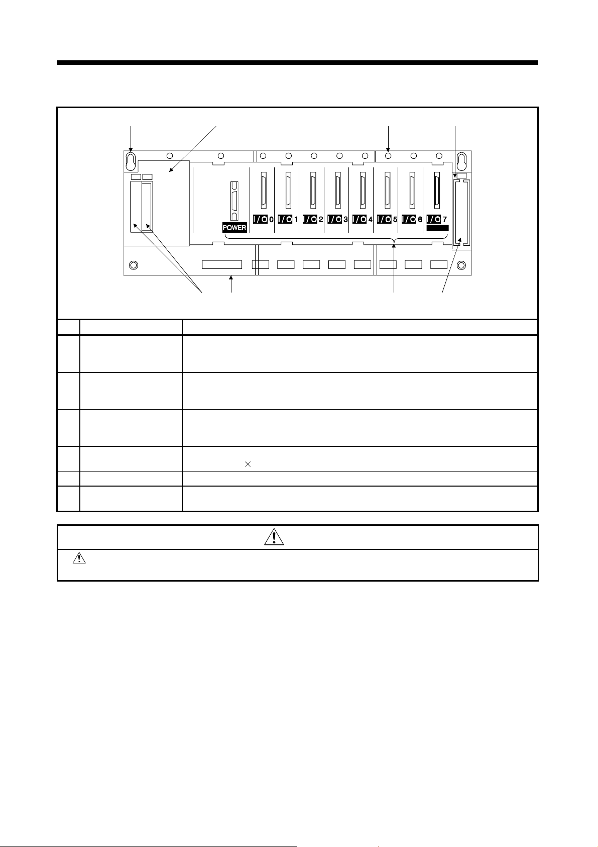
1. SPECIFICATIONS OF MOTION SYSTEM COMPONENTS
(d) Extension base unit (A168B)
5) 2) 4)
IN
OUT
6)1) 3)
No. Name Application
Extension cable
1)
connector
Connects to the signal communications connector on the main base unit or bus
coupling type GOT with the extension cable.
Take off the supplied connector cover before connecting the extension cable.
A cover for protecting the extension cable connector.
2) Base cover
When connecting to bus coupling type GOT, cut out the area surrounded by the groove
under the word “OUT” on the base cover with side cutters, or other appropriate tool.
Connectors to mount the Power module, I/O module, and special-function modules.
3) Module connector
Install the supplied connector cover or blank cover (A1SG60) to prevent dust
penetrating empty connector spaces.
4) Unit fixing screw
5) Base mounting hole
6) DIN rail hooks
Screws to fix the unit to the base.
Screw size M4
12.
Slots for mounting the base unit onto the control board panel (for M5 screws).
Hooks to attach to the DIN rail.
A168B........................2
2)
OUT
A168B
*1
1)
CAUTION
*1 : Install the supplied blind cap or blank cover (A1SG60) to prevent dust penetrating the empty
connector spaces. Failure to do so may cause malfunctioning.
1 − 32
Page 45

1. SPECIFICATIONS OF MOTION SYSTEM COMPONENTS
(3) Selection of base units and extension cables
(a) Selection of main base unit
Choose the main base unit according to the number of pulse
generator/synchronous encoder interface modules (A172SENC) and limit output
modules (A1SY42) fitted to the main base (number of motion slots) and the
number of sequencer I/O slots (number of sequence slots).
Selection of Main Base
Main Base Model
A172B 1 1
A175B 1 4
A178B 1 7
A178B-S1 2 6
A178B-S2 4 4
A178B-S3 8 0
(No. of A172SENCs and A1SY42s)
(b) Selection of sequence extension base unit and extension cable
Choose the sequence extension base according to the number of MELSEC-A
series I/O modules fitted to the sequence extension base unit.
Selection of sequence Extension Base Unit
Extension Base Unit
Model
A1S65B
A1S68B
A168B
For extension power supply + 5 slots, applicable to system with up
to one extension base.
For extension power supply + 8 slots, applicable to system with up
to one extension base.
For extension power supply + 8 slots, applicable to system where
up to one extension base and GOT are bus-connected.
No. of Motion Slots
MELSEC-A Series I/O Modules
No. of Sequence Slots
Choose the extension cable according to the distance between the main base
unit and sequence extension base unit and the type of the sequence extension
base unit. Note that the overall distance should be within 3m (9.84ft.).
Selection of Extension Cable
Extension Cable
Model
A1SC01B
A1SC03B 330 mm (13 inch)
A1SC07B 700 mm (27.58 inch)
A1SC12B 1200 mm (47.28 inch)
A1SC30B 3000 mm (118.2 inch)
A1SC60B 6000 mm (236.4 inch)
A1SC05NB 450 mm (17.73 inch)
A1SC07NB 700 mm (27.58 inch)
A1SC30NB 3000 mm (118.2 inch)
A1SC50NB 5000 mm (196.9 inch)
55 mm (2.17 inch), flat cable for horizontal
extension
Length mm (inch)
Type of Sequence
Extension Base Unit
For A1S6
For A6
B
POINT
Choose the motion modules and MELSEC-A series I/O modules so that the
sum of 5VDC consumed currents of the CPU module, motion modules,
MELSEC-A series I/O modules, synchronous encoders and manual pulse
generators connected to the main base unit is within 5 (A) for the
A173UHCPU/A172SHCPUN or 3 (A) for the A171SHCPUN.
B/A168B
1 − 33
Page 46

1. SPECIFICATIONS OF MOTION SYSTEM COMPONENTS
(4) Motion slots
When using the A172SENC and limit output module (A1SY42), load them into
P I/O
(motion slots) of the main base.
Motion slot
(5) Main base unit emergency stop circuit
(a) By opening the main base unit emergency stop (EMG) circuit, it is possible
to effect an emergency stop all axes of the separate servo amplifiers (MRH-BN/MR-J2S-B/MR-J2-B) simultaneously.
After an emergency stop, eliminate the cause of the emergency stop and
reset the emergency stop by closing the emergency stop circuit (turning
EMG circuit ON). (In the event of an emergency stop, the servo error
detection signal does not come ON.)
An example of emergency stop wiring connections is shown below.
Main base unit
OUT
Emergency stop
24VDC
EMG
EMG.COM
(b) Do not use the emergency stop terminals of the separate servo amplifiers.
If an independent emergency stop circuit is also required at a separate
servo amplifier, provide an external circuit that shuts off the power supply to
the separate servo amplifier.
1 − 34
Page 47

1. SPECIFICATIONS OF MOTION SYSTEM COMPONENTS
n
(6) Connection and I/O assignment of base units
This section explains the way to connect the base units and the concept of
sequence I/O assignment.
Use the extension cables for connection of the main base unit and extension
base unit and connection of the extension base units.
When connecting the graphic operation terminal (GOT) by the bus, load it to
the last extension base.
When automatic I/O assignment is executed (when the CPU module is started
without I/O assignment being made on the positioning software package), the
I/O numbers are automatically assigned, starting from 000, according to the
number of occupying points of the I/O modules loaded to the sequencer slots,
and each empty slot is assigned 16 points as occupied. Also, one base unit
occupies eight sequencer slots, independently of the physical number of
sequencer slots. Therefore, for example, when an extension base unit is
connected to the A175B main base unit (one motion slot and four sequencer
slots), the A175B main base unit has only four sequencer slots physically but
automatic assignment is made as if four 16-point slots are occupied between
the main and extension base units. To avoid the occupation of empty slots by
automatic assignment, setting the corresponding slots as empty (S0) in the I/O
assignment of the positioning software package allows the number of occupied
points to be set to 0 in the I/O assignment.
•
Example of using the A172B main base (when a 16-point module is loaded to
each slot)
1
3
Main base unit
(A172B)
CPU
module
Power supply
A1S68B extension base unit
8
80
to
8F
Motion slot
Sequencer slot No.
0
00
to
0F
10
9
11
90
A0
B0
to
to
to
9F
AF
BF
12
C0
to
CF
13
D0
to
DF
14
E0
to
EF
2
Vacant, 16 points 10 to 1F
Vacant, 16 points 20 to 2F
The I/O numbers indicated are
those set by automatic I/O
15
assignment. When empty slots
F0
1 to 7 are set to 0 points (S0)
in the I/O assignment, the I/O
numbers of slot 8 of the extensio
to
base are 10 to 1F.
FF
5
4
67
Vacant, 16 points 30 to 3F
Vacant, 16 points 40 to 4F
Vacant, 16 points 50 to 5F
Vacant, 16 points 60 to 6F
Vacant, 16 points 70 to 7F
POINT
1) Max. number of actual I/O points
A173UHCPU:2048 points, A172SHCPUN:1024 points, A171SHCPUN:512
points. The real I/O points can be used within the range of one extension
base.
2) When using the bus connection type GOT, use the A168B.
3) Use the extension cable within 3m (9.84ft.) length.
1 − 35
Page 48

1. SPECIFICATIONS OF MOTION SYSTEM COMPONENTS
2
s
•
Example of using the A175B main base (when a 16-point module is loaded to
each slot)
Main base unit
(A175B)
CPU
Motion slot
Sequencer slot No.
0
123
00
10
20
30
to
to
to
to
0F
1F
2F
3F
4567
Vacant, 16 points 40 to 4F
Vacant, 16 points 50 to 5F
Vacant, 16 points 60 to 6F
Vacant, 16 points 70 to 7F
1st extention stage
nd extention stage,
lot 0
Sequencer slot No.
10
8
9
11
12
13
14
80
90
A0
B0
C0
D0
E0
to
to
to
to
to
to
to
module
Power supply
8F
9F
AF
BF
CF
DF
EF
A168B extension base unit
GOT
100
(special unit)
11F
•
Example of using the A178B-S2 main base (when a 16-point module is
The I/O numbers indicated are
15
those set by automatic I/O
F0
assignment. When empty slots
4 to 7 are set to 0 points (S0) in
the I/O assignment, the I/O
to
numbers of slot 8 of the extension
base are 40 to 4F.
FF
loaded to each slot)
Main base unit
(A178B-S2)
Motion slot
0
00
Sequencer slot No.
123
10
20
30
5
4
7
6
11
B0
to
BF
to
0F
12
C0
to
CF
CPU
10
8
9
80
90
A0
to
to
to
module
Power supply
8F
9F
AF
A1S68B extension base unit
to
1F
13
D0
to
DF
1 − 36
14
E0
to
EF
to
to
2F
3F
The I/O numbers indicated are
15
those set by automatic I/O
F0
assignment. When empty slots
4 to 7 are set to 0 points (S0)
in the I/O assignment, the I/O
to
numbers of slot 8 of the
extension base are are 40 to 4F.
FF
Vacant, 16 points 40 to 4F
Vacant, 16 points 50 to 5F
Vacant, 16 points 60 to 6F
Vacant, 16 points 70 to 7F
Page 49

1. SPECIFICATIONS OF MOTION SYSTEM COMPONENTS
•
Example of using the A178B-S3 main base (when a 16-point module is
loaded to each slot)
Sequencer slot No.
1
0
234567
Vacant, 16 points 10 to 1F
Vacant, 16 points 20 to 2F
Vacant, 16 points 00 to 0F
Vacant, 16 points 30 to 3F
Vacant, 16 points 40 to 4F
Vacant, 16 points 50 to 5F
Main base unit
(A178B-S3)
CPU
Motion slot
Vacant, 16 points 60 to 6F
Vacant, 16 points 70 to 7F
10
8
9
11
12
80
90
A0
B0
C0
to
to
to
to
to
module
Power supply
8F
9F
AF
BF
CF
A1S68B extension base unit
13
D0
to
DF
14
E0
to
EF
The I/O numbers indicated are those
15
set by automatic I/O assignment.
F0
When empty slots 0 to 7 are set to 0
points (S0) in the I/O assignment, the
to
I/O numbers of slot 8 of the extension
base are are 00 to 0F.
FF
1 − 37
Page 50

1. SPECIFICATIONS OF MOTION SYSTEM COMPONENTS
1.5.4 Manual Pulse Generator/Synchronous Encoder Interface Module A172SENC receive external signals required for positioning control (motion control
signals and tracking inputs), manual pulse generator inputs, and synchronous
encoder inputs.
(1) Specifications
Table 1.9 A172SENC Specifications
Item Specification
Model Name A172SENC
Motion control signals: 32 points
(8 points each for upper stroke limit, lower stroke limit, STOP input, near-
No. of inputs
Rated input voltage 12/24VDC
Motion control
signal input,
tracking input
Brake output
Manual pulse
generator input or
incremental
synchronous
encoder
Serial absolute
synchronous
encoder input
Power consumption (5 VDC) 0.42
Product weight (kg) (lb) 0.22 (0.49)
Rated input current 12VDC 2mA/24VDC 4mA
Operating voltage
range
ON voltage/current 7.0 VDC min./1.0 mA min.
OFF voltage/current 1.8 VDC max./0.18 mA max.
Response time
Tracking input
response time
No. of outputs 1 point
Rated load voltage 24 VDC
Operating load
voltage range
Maximum load
current
Response time
No. of modules 1
H voltage 3.0 to 5.25 V
L voltage 0 to 1.0 V
Maximum input
frequency
Applicable type
No. of modules 1
Applicable types MR-HENC
Position detection
method
Resolution 16384 PLS/rev
zero point DOG/speed-position changeover signal)
Tracking enable signal : 1 point
Total : 33 points
10.2 to 26.4VDC
OFF
ON 2 ms max.
ON
OFF 3 ms max.
OFF
ON 0.5 ms max.
ON
OFF 0.5 ms max.
21.6 to 30 VDC (peak voltage 30 VDC)
0.1 A (max. rush current: 0.4A, 10 ms max.)
OFF
ON 2 ms max.
ON
OFF 2 ms max.
100 kpps max.
Voltage-output type (5 VDC), Recommended product: MR-HDP01
Differential-output type: 26LS31 or equivalent
Selectable by connector wiring
Absolute
1 − 38
Page 51

1. SPECIFICATIONS OF MOTION SYSTEM COMPONENTS
(2) Description of Parts
(a) A172SENC
1)
3)
2)
No. Name Application
Display the input status from external equipment and errors detected by self-diagnosis.
LED Description
1) LED indicators
2) CTRL connector
3) PULSER connector
4) SY.ENC connector
PX0 to
PX1F
TRA Input start signal from synchronous encoder.
Connector for motion control signal input and tracking signal input of each axis.
Manual pulse generator/incremental synchronous encoder input connector.
Serial absolute synchronous encoder input connector.
Indicators to display the motion control signal input status of each
axis.
4)
1 − 39
Page 52

1. SPECIFICATIONS OF MOTION SYSTEM COMPONENTS
(3) Selection of A172SENC module and connection with external equipment
(a) Number of A172SENC modules
Determine the number of A172SENC modules according to the number of
control axes which use such external signals as upper and lower stroke limit and
near-zero point dog signals and the number of manual pulse
generators/synchronous encoders used.
You can use up to four modules for the A173UHCPU or only one module for the
A172SHCPUN or A171SHCPUN.
A172SENC Specificati ons
Signal/Connected External
Equipment
Servo external signal
Manual pulse
generator/incremental
synchronous encoder
(Voltage/differential output type)
Serial absolute synchronous
encoder
Upper stroke limit input
Lower stroke limit input
Stop signal input
Near-zero point dog/speed-position
change signal input
Tracking enable input: 1 point
Electromagnetic brake command
output: 1 point
1 unit
1 unit
Usable Number per A172SENC
Load the A172SENC to P I/O (motion slot) of the main base.
Motion slot
8 points
(for 8 axes)
OUT
1 − 40
Page 53

1. SPECIFICATIONS OF MOTION SYSTEM COMPONENTS
(b) Connection of manual pulse generators/synchronous encoders
Manual pulse generators are available in voltage output type and differential
output type, and synchronous encoders are available in voltage
output/differential output type and serial absolute output type (Model: MRHENC). Since these types differ in connectors and connection methods, design
according to the connection system described below. (The synchronous
encoders are used only in the SV22 virtual mode.)
In addition, the usable numbers of manual pulse generators and synchronous
encoders differ between the CPU modules.
CPU Module Manual Pulse Generator Synchronous Encoder
A173UHCPU 3 4
A172SHCPUN/A171SHCPUN 1 1
1) Connection of voltage output type and differential output type manual
pulse generators and incremental synchronous encoders
Use the PULSER connector at the A172SENC module front to connect any
of the voltage output type and differential output type manual pulse
generators and incremental synchronous encoders.
The pin layout and connection of the PULSER connector are described
below.
PULSER connector
PIN No. Signal Name PIN No. Signal Name
1SG11SG
2 Vacant 12 Vacant
*2 4 HA1 14 HB1 *2
*3
*1 Inputs from manual pulse generator switched by HPSEL. Unconnected selects voltage-output type, HPSEL=SG
*2, *3 Connect the manual pulse generator connector cable wires according to the output type of the manual pulse
3HZ113Vacant
5SG15SG
6 P516P5
7 HA2P 17 HA2N
8 HB2P 18 HB2N
9 HZ2P 19 HZ2N
10 Vacant 20 HPSEL *1
selects differential-output type.
generator, as described belo w .
*2 Voltage -output type
Connect the A-phase signal to Pin 4 (HA1) and the B-phase signal to Pin 14 (HB1).
*3 Differential-output type
Connect the A-phase signal to Pin 7 (HA2P) and the A-phase inverse signal to Pin 17 (HA2N), the Bphase signal to Pin 8 (HB2P) and the B-phase inverse signal to Pin 18 (HB2N).
Applicable connector
model names
10120-3000VE
connector
10320-52F0-008 (Standard
connector cover accessories)
(Manufactured by
Sumitomo 3M )
*3
*Also available as MR-CON1.
1 − 41
Page 54

1. SPECIFICATIONS OF MOTION SYSTEM COMPONENTS
•
Interface between PULSER connector and voltage-output
manual pulse generator/incremental synchronous encoder
Pin No.
Input or
Output
Input
Signal Name
A
Manual
pulse
generator,
phase A
Manual
pulse
generator,
phase B
+
A
−
B
+
B
−
P5 6 16
SG 1 5 11 15
PULSER
Connector
Voltage-Output
Type
4
14
Wiring Example Internal Circuit Specification Description
Rated input
•
voltage 5.5 VDC
max.
HIGH level
•
3 VDC to 5.25
VDC/2 mA
LOW level
•
1 VDC max./ 5 mA
min.
Manual pulse
generator/
synchronous
encoder
1K
A
1K
B
5V
0V
To connect manual
pulse generator
phases A,B
Pulse width
•
10 s min.
5 s min.
5 s min.
(Duty ratio:50%)
Rise, fall time
•
.......1
s max.
Phase difference
•
Phase A
Phase B
(1) Positioning
(2) Positioning
2.5 s min.
address
increases if
Phase A leads
Phase B.
address
decreases if
Phase B leads
Phase A.
1 − 42
Page 55

1. SPECIFICATIONS OF MOTION SYSTEM COMPONENTS
•
Interface between PULSER connector and differential-output
manual pulse generator/incremental synchronous encoder
Pin No.
Input or
Output
Input
Signal Name
A
Manual
pulse
generator,
phase A
Manual
pulse
generator,
phase B
+
A
−
B
+
B
−
P5 6 16
SG 1 5 11 15
PULSER
Connector
Voltage-Output
Type
7
17
8
18
Wiring Example Internal Circuit Specification Description
Rated input
•
voltage 5.5 VDC
max.
HIGH level
•
3 VDC to 5.25
VDC/2 mA max.
LOW level
•
1 VDC max./ 5 mA
max.
Manual pulse
generator/
synchronous
encoder
A
A
B
B
5V
0V
To connect manual
pulse generator
phases A,B
Pulse width
•
10 s min.
5 s min.
5 s min.
(Duty ratio:50%)
Rise, fall time
•
.......1
s max.
Phase difference
•
Phase A
Phase B
(1) Positioning
(2) Positioning
2.5 s min.
address
increases if
Phase A leads
Phase B.
address
decreases if
Phase B leads
Phase A.
•
Connection examples
Connection of volta ge- output manu al pulse gener ator Connection of different ial -output manu al pu lse g ener ator
A172SENC
Signal name Signal name
HA1
HA2
SG
SG
*1*2
Manual pulse
generator side
A
B
0V
5V
SG
P5
A172SENC
HA2P
HA2N
HB2P
HB2N
SG
SG
HPSEL
CAUTION
P5
generator side
*1*2
*1: The 5 VDC power supply from the A172SENC must not be connected if a separate power
supply is used as the manual pulse generator power supply.
If a separate power supply is used as the manual pulse generator power supply, use a 5 V
stabilized power supply. Any other power supply may cause a failure.
*2: Total connector cable length not to exceed 30 m (98.4 ft.)
Manual pulse
A
A
B
B
0V
5V
1 − 43
Page 56

1. SPECIFICATIONS OF MOTION SYSTEM COMPONENTS
(
)
2) Connection of serial absolute synchronous encoder (MR-HENC)
Use the SY.ENC connector at the A172SENC module front to connect the
serial absolute synchronous encoder (MR-HENC).
Use the MR-HSCBL
synchronous encoder (MR-HENC) and SY.ENC connector.
The pin layout and connection of the SY.ENC connector are described
below.
SY.ENC connector
PIN No. Signal Name PIN No. Signal Name
10 Vacant 20 SD
9 Vacant 19 Vacant
8 P5 18 Vacant
7P517SG
6 Vacant 16 P5
5 Vacant 15 SG
4 MR 14 BAT
3MRR13MDR
2SG12MD
1 SG 10 Vacant
3) Interface with external equipment
The interface between the SY.ENC connector and external equipment is
described below.
(a) Wiring precautions
1) Tighten the screws after connecting the connector.
CPU A172S
ENC
M encoder cable between the serial absolute
CPU : A173UHCPU/A172SHCPUN/A171SHCPUN
A172SENC : Manual pulse generator/
synchronous encoder
interface module
Applicable connector model
names PCR-S20FS
connector PCR-LS20LA1
connector cover
(Manufactured by HONDA
TSUSHIN KOGYO
CO.,LTD
SY.SNC
connector
Serial absolute synchronous encoder cable
(MR-HSCBL M)
Serial absolute synchronous encoder
MR-HENC
1 − 44
Page 57

1. SPECIFICATIONS OF MOTION SYSTEM COMPONENTS
)
CAUTION
Connect the SY.ENC connector to external equipment using a shielded cable. To reduce
electromagnetic interference, do not position the cable close to, or bundle it with, power or main
circuit cables. A clearance of at least 200 mm (0.66 inch) to other cables is required.
Connect the shield wire of the shielded cable to the FG terminal of the external equipment.
When increasing the cable length, use the cable within 30m (98.36 ft). Note that the cable should
be run in the shortest possible distance to avoid induced noise.
Always wire the cables when power is off. Not doing so can damage the output circuit if any of
the output signal cables makes contact with the power supply or the output signal cables make
contact with each other.
Use extreme care when wiring the cables. Wrong wiring can damage the internal circuitry.
•
Details of encoder cable connections
MR
MRR
P5
SG
4
3
7
1
C
D
S
R
MR
MRR
P5
SG
4
3
7
1
C
D
S
R
8
P5
2
SG
14
BAT
SG
15
SD
20
PCR-S20FS
connector
(SY.ENC end)
*1
MR-HSCBL2M , MR-HSCBL5M
(2m (6.56ft.)) (10m (32.79ft))
Model name for encoder connector set (MR-JSCNS
*1 : Encoder cables are the same as HA-UH K,HC-SF/RF/UF (2000r/min) series motor cables.
*2: The encoder connector set may also be used as the detector connector set for HA-UH
SF/RF/UF (2000r/min) series motor.
F
G
N
MS3106B20-29S
connector
(synchronous
encoder end)
P5
8
2
SG
P5SG16
17
BAT
14
SG
15
SD
20
PCR-S20FS
connector
(SY.ENC end)
*1
MR-HSCBL10M to MR-HSCBL30M
(10m to 30m (98.36ft.) )
F
G
N
MS3106B20-29S
connector
(synchronous
encoder end)
*2
K,HC-
1 − 45
Page 58

1. SPECIFICATIONS OF MOTION SYSTEM COMPONENTS
•
Interface between SY.ENC connector and external equipment
Input or
Output
Signal Name
MR
MRR
Pin No.
SY.ENC
Connector
4
3
Wiring Example Internal Circuit Specification Description
Transmission
•
method: serial
Serial
synchronous
encoder
communications
Position detection
•
method: absolute
Input
P5
SG
BAT
SD
*3
7, 8, 16
1, 2, 15, 17
*3: Connect when using MR-HSCB L10 M to MR -HS CBL30M.
*3
14
20
(c) Connection of servo external signals
There are the following servo external signals.
The A172SENC is assigned a set of input numbers per axis, with the exception
of the tracking enable signal and electromagnetic brake command output. Make
the system settings of the positioning software package to determine the I/O
numbers corresponding to the axis No.s.
Servo External
Signal
Upper stroke limit
input (FLS)
Lower stroke limit
input (RLS)
Stop signal input
(STOP)
Near-zero point
dog/speed-position
change input
(DOG/CHANGE)
Tracking enable
signal input
Electromagnetic
brake command
output
For detection of upper and lower stroke
limits
For stopping under speed or positioning
control
For detection of near-zero point dog at
near-zero point dog or count type home
position return or for switching from speed
to position under speed-position change
control.
Synchronous encoder input start signal
For command output to electromagnetic
brake
Application
Number of Points on
One A172SENC
8 points each
(1 point/1 axis each)
1 point each
1 − 46
Page 59

1. SPECIFICATIONS OF MOTION SYSTEM COMPONENTS
Use the CTRL connector at the A172SENC module front to connect the servo
external signals.
The pin layout and connection of the CTRL connector are described below.
The following pin layout is the front view as seen from the CTRL connector front
of the A172SENC.
POINT
Signal No.s 1 to 8 can be assigned to the specified axes. To make
assignment, make the system settings of the positioning software package.
CTRL connector
PIN No. Signal Name PIN No. Signal Name
A1 BRK.COM B1 COM
External input
Signal No. A4 V acan t B4 TRA Signal No.
signal name
DOG/CHANGE A5 PX1F B5 PXF DOG/CHANGE
STOP A6 P X1E B6 PXE STOP
8
7
6
5
RLS A7 PX1D B7 PXD RLS
FLS A8 PX1C B8 PXC FLS
DOG/CHANGE A9 PX1B B9 PXB DOG/CHANGE
STOP A10 PX1A B10 PXA STOP
RLS A11 PX19 B11 PX9 RLS
FLS A12 PX18 B12 PX8 FLS
DOG/CHANGE A13 PX17 B13 PX7 DOG/CHANGE
STOP A14 PX16 B14 PX6 STOP
RLS A15 PX15 B15 PX5
FLS A16 PX14 B16 PX4 FLS
DOG/CHANGE A17 PX13 B17 PX3 DOG/CHANGE
STOP A18 PX12 B18 PX2 STOP
RLS A19 PX11 B19 PX1 RLS
FLS A20 PX10 B20 PX0 FLS
Applicable connector model name.......FCN-361J040-AU connector (manufactured by Fujitsu)
A2 BRK B2 COM
A3 Vacant B3 Vacant
FCN-360C040-B connector cover
External input
signal name
RLS
4
3
2
1
(Standard
accessories)
DOG/CHANGE, STOP, RLS, FLS functions of each axis (1 to 8)
DOG/CHANGE............Near-zero point do g/sp ee d- positi on ch ang e si gn al
STOP ..........................Stop signal
RLS .............................Lower stroke limit
FLS..............................Upper stroke limit
1 − 47
For signal details, refer to the
programming manual.
Page 60

1. SPECIFICATIONS OF MOTION SYSTEM COMPONENTS
•
Interface between CTRL connector and servo external signal
Input or
t
Outpu
PX0, PX4, PX8, PXC
PX10, PX14, PX18, PX1C
PX1, PX5, PX9, PXD
PX11, PX15, PX19, PX1D
PX2, PX6, PXA, PXE
PX12, PX16, PX1A, PX1E
PX3, PX7, PXB, PXF
PX13, PX17, PX1B, PX1F
Input
Output
Signal Name
TRA B4
Power B1 B2
BRK A2
BRK, COM A1
Pin Number
CTRL Connector
B20
B16
A20
A16
B19
B15
A19
A15
B18
B14
A18
A14
B17
B13
A17
A13B9A9B5A5
B12
A12B8A8
B11
A11B7A7
B10
A10B6A6
Wiring Example Internal Circuit Specification Description
Supply voltage
Upper stroke
limit input
Lower stroke
limit input
Stop signal
input
Near point DOG/
speed-position
changeover
command
TRA signal
+
-
5VDC to
24VDC
Brake
+
-
24VDC
6.8k
6.8k
6.8k
6.8k
6.8k
•
12 to 24 VDC
(10.2 to 26.4 VDC,
stabilized power
supply)
HIGH level
•
7.0 VDC
min./1.0mA min.
LOW level
•
1.8 VDC max./0.2
mA max.
Rated load voltage
24 VDC (21.6 to 30
VDC), 0.1 mA max.
FLS
RLS
STOP
DOG/CHANGE
Tracking enable
signal input.
Generates
•
interrupts to
A173UHCPU/
A172SHCPUN/
A171SHCPUN.
Starts counter
•
operation.
Common terminals
for motion control
signals, external
signal and TRA.
Brake signal output
CAUTION
Always use a shielded cable for connection of the SY.ENC connector and external equipment,
and avoid running it close to or bundling it with the power and main circuit cables to minimize the
influence of electromagnetic interference. (Separate them more than 200mm (0.66 inch) away.)
Connect the shield wire of the connection cable to the FG terminal of the external equipment.
Make parameter setting correctly. Incorrect setting may disable the protective functions such as
stroke limit protection or may not provide the brake output, damaging the module.
Always wire the cables when power is off. Not doing so can damage the output circuit if any of
the output signal cables makes contact with the power supply or the output signal cables make
contact with each other.
Use extreme care when wiring the cables. Wrong wiring can damage the internal circuitry.
1 − 48
Page 61

1. SPECIFICATIONS OF MOTION SYSTEM COMPONENTS
)
)
1.5.5 Teaching Unit (1) Names of parts
(a) A30TU-E
3)
Emergency
Valid
Invalid
MITSUBISHI
A30TU-E
A30TU-E SV13 Ve
1)
*Data *Monitor
*PROG *Test
Press the mode key.
Stop
2
6)
DATA
ITEM
:
79
WRITE
4
STORE
1
SHIFT
AXIS
NO.
8
D
5
A
2
ERROR
RESET
JOG - JOG +
TEST
STOP
CLEAR
#
SP
E
F
6
STEP-
B
C
3
STEP+
MDI
-
0.
RETURN
CAN
GO
4
No. Name Application
1) Display
4-line
With back-lighted auto light off
16-character LCD display
With contrast adjusting knob
2) Emergency stop key Shuts off servo power to stop all operations.
3) Valid/Invalid switch Changes over the operations of the teaching box between valid and invalid.
4) Operation keys Operation key switches of the teaching box
5) Internal buzzer
Buzzer sounds when key input or any alarm occurs.
It is also possible to set the buzzer so that it does not sound for key input.
6) Contrast adjusting knob For contrast adjustment of display
1 − 49
Page 62

1. SPECIFICATIONS OF MOTION SYSTEM COMPONENTS
(b) A31TU-E
InvalidValid
Schematic
3)
drawing of
2)
front panel
Emergency Stop
MITSUBISHI A31TU-E
A31TU-E SV13 Ve
1)
*Data *Monitor
*PROG *Test
Press the mode key.
Schematic drawing
of rear panel
6)
DATA
ITEM
:
79
WRITE
4
STORE
1
SHIFT
AXIS
NO.
8
D
5
A
2
ERROR
RESET
JOG - JOG +
TEST
STOP
CLEAR
#
SP
E
B
6
3
MDI
0.
CAN
F
C
-
STEP-
STEP+
RETURN
GO
4)
No. Name Application
4-line 16-character LCD display
1) Display
With back-lighted auto light off
With contrast adjusting knob
2) Emergency stop key Shuts off servo power to stop all operations.
3) Valid/Invalid switch Changes over the operations of the teaching box between valid and invalid.
4) Operation keys Operation key switches of the teaching box
5) Internal buzzer
Buzzer sounds when key input or any alarm occurs.
It is also possible to set the buzzer so that it does not sound for key input.
6) Contrast adjusting knob For contrast adjustment of display
7) Deadman switch
Turns on the switch to enable servo operation: turns off the switch to shut off the servo
power.
7)
POINT
A dead-man switch is used for jogging operated from the teaching box. To operate the switch, press and
hold it down. Releasing the deadman switch turns off servo power, bringing the servo motor to an
immediate stop.
1 − 50
Page 63

1. SPECIFICATIONS OF MOTION SYSTEM COMPONENTS
p
(2) Selection of teaching unit and connection with CPU module
(a) Selection of teaching unit
There are the A30TU-E and A31TU-E teaching units. Refer to the following
table for selection.
Selection of Teaching Unit
Comparison A30TU-E A31TU-E
Dead-man switch
Emergency stop
*1
Without With
With (signal on semiconductor
level)
With (signal on relay level)
Directly unconnectable
Via A31TUCBL03M
Connection with CPU Directly connectable
External circuit required
(In direct connection, CPU
module does not operate.)
*1: Releasing the deadman switch turns off servo power.
(b) Connection of A31TU-E unit (teaching unit with deadman switch) and CPU
module
To connect the A31TU-E teaching unit with deadman switch and the CPU
module, use the A31TUCBL03M for connection within the panel and plug its
A31TU-E side connector into the operator panel surface for A31TU-E
connection. When using the A31TU-E unit, use it by plugging it into the
connector on the operator panel surface. When not using the A31TU-E, fit the
A31SHORTCON into the connector on the operator panel surface.
The A31TUCBL03M's signal wires connected to the external circuit, e.g. EMG
and EMGL, are used for external safety circuit connection for the emergency
stop switch and deadman switch of the A31TU-E. Refer to Section 2.3(2) for
details of the external circuit.
Control panel
CPU module
When using the A31TU-E, be sure to use the A31TUCBL03M.
When the A31TU-E is not connected, be sure to connect the
A31SHORTCON. Failing to do this could result in the system entering an
emergency stop state.
An external circuit is essential to form a safety circuit. (For details of external
circuit configuration, refer to the section 2.3.)
A31TUCBL03M
EMG
EMGL
External circuit
*2: The CPU module does not o
EMG1
EMG2
POINT
DED1
DED2
A31TUCBL03M connector
erate if the A31TU-E and CPU module are connected directly.
A31SHORTCON
(Fitted when A31TU-E is not used)
A31TU-E
*2
1 − 51
Page 64

1. SPECIFICATIONS OF MOTION SYSTEM COMPONENTS
(c) Connection of A30TU-E and CPU module
(3) Applicable teaching unit version
Teaching unit version applicable to CPU module is as follows:
Model Name Applicable Version
A30TU-E D or later
A31TU-E B or later
Teaching unit version is marked on the rated name plate at the rear panel of
the unit.
(4) A30TU-E rated name plate
Unit version
A30TU-E
D
DATE
MITSUBISHI ELECTRIC CORPORATION
(5) A31TU-E rated name plate
MITSUBISHI
TEACHING UNIT
MODEL
A31TU-E
DATE B
MITSUBISHI ELECTRIC CORPORATION
MADE IN JAPAN BC370D070H02
Unit version
1 − 52
Page 65

1. SPECIFICATIONS OF MOTION SYSTEM COMPONENTS
1.5.6 SSCNET Cables and Termination Resistor and Their Connection Method
Motion controller
CPU module
SSCNET cable overall length
1)+2) 30m(98.36ft.)
3)
1)
IN OUT
Servo amplifier
MR-H-BN
MR-J2S-B
MR-J2-B
2)
IN OUT
Servo amplifier
MR-H-BN
MR-J2S-B
MR-J2-B
No. Product Model Description
1)
2)
1)
SSCNET
cable
2)
2)
Termination
3)
resistor
MR-HBUS
M
Cable length within
(0.5m (1.64ft.), 1m (3.25ft.),
5m (16.39ft.))
MR-J2HBUS
M-A
Cable length within
(0.5m (1.64ft.), 1m (3.28ft.),
5m (16.39ft.))
MR-J2HBUS
M
Cable length within
(0.5m (1.64ft.), 1m (3.28ft.),
5m (16.39ft.))
MR-TM
MR-A-TM
For connection of CPU and servo
amplifier (MR-H-BN)
For connection of servo amplifier (MR-HBN) and servo amplifier (MR-H-BN)
For connection of CPU and servo
amplifier (MR-J2-B)
For connection of servo amplifier (MR-HBN) and servo amplifier (MR-J2S-B/MRJ2-B)
For connection of servo amplifier (MRJ2S-B/MR-J2-B) and servo amplifier (MRJ2S-B/MR-J2-B)
Fitted to the SSCNET's last servo
amplifier (MR-H-BN).
Fitted to the SSCNET's last servo
amplifier (MR-J2S-B/MR-J2-B).
(1) Performance specifications
(a) MR-HBUS
Model
Cable length (m (ft.)) 0.5 (1.64) 1 (3.28) 5 (16.39)
Item
M
MR-HBUS05M MR-HBUS1M MR-HBUS5M
(b) MR-J2HBUS M (-A)
Item
Model
Cable length (m (ft.)) 0.5 (1.64) 1 (3.28) 5 (16.39)
MR-J2HBUS05M
(-A)
MR-J2HBUS1M
(-A)
MR-J2HBUS5M
(-A)
1 − 53
Page 66

1. SPECIFICATIONS OF MOTION SYSTEM COMPONENTS
(2) Connection of CPU module and servo amplifiers
This section explains how to connect the CPU module.
Use the SSCNET to connect the CPU module and servo amplifiers. When
using the A172SHCPUN/A171SHCPUN, only one line of SSCNET is available
for servo amplifier connection (use SSCNET1). The A173UHCPU can use up
to four lines for servo amplifier connection. One line of SSCNET allows
connection of up to eight servo amplifies.
As the SSCNET cables and termination connector used depend on the servo
amplifiers, refer to the following connection example.
The SSCNET cables and termination connector used in the connection
example are any of the models shown in the following table.
Name Model Name Depiction in Connection Example
MR-HBUS M
MR-J2HBUS MSSCNET cable
Termination
connector
MR-J2HBUS
MR-TM
MR-A-TM
M-A
(a) MR-H-BN configuration
CPU module MR-H-BN MR-H-BN MR-H-BN
Battery
MR-BAT,
A6BAT
Battery
MR-BAT,
A6BAT
(b) MR-J2S-B/MR-J2-B configuration
CPU module
MR-J2S-B
/MR-J2-B
Battery
MR-BAT,
A6BAT
MR-J2S-B
/MR-J2-B
Battery
MR-BAT,
A6BAT
Battery
MR-BAT,
A6BAT
MR-J2S-B
/MR-J2-B
Battery
MR-BAT,
A6BAT
Termination
connector
Termination
connector
1 − 54
Page 67

1. SPECIFICATIONS OF MOTION SYSTEM COMPONENTS
(c) MR-J2S-B/MR-J2-B+MR-H-BN configuration
MR-J2S-B
/MR-J2-B
MR-H-BN
CPU module
MR-J2S-B
/MR-J2-B
Termination
connector
CPU module
CPU module
Battery
MR-BAT,
A6BAT
MR-H-BN
Battery
MR-BAT,
A6BAT
MR-J2S-B
/MR-J2-B
Battery
MR-BAT,
A6BAT
Battery
MR-BAT,
A6BAT
Battery
MR-BAT,
A6BAT
MR-J2S-B
/MR-J2-B MR-H-BN
Battery
MR-BAT,
A6BAT
Battery
MR-BAT,
A6BAT
MR-J2S-B
MR-H-BN
Battery
MR-BAT,
A6BAT
/MR-J2-B
Battery
MR-BAT,
A6BAT
Termination
connector
Termination
connector
1 − 55
Page 68

1. SPECIFICATIONS OF MOTION SYSTEM COMPONENTS
(3) Servo amplifier axis numbers and axis No. (dno.) setting
The axis No.s are used to set the axis numbers of the SSCNET-connected
servo amplifiers in the program. Axis No.s 1 to 32 can be set for the
A173UHCPU, 1 to 8 for the A172SHCPUN, and 1 to 4 for the A171SHCPUN.
To set the axis No.s, assign the axis No.s to the axis numbers set with the axis
selection switches (rotary switch) of the servo amplifiers (Positions 0 to 7 of the
rotary switch correspond to d1 to d8 on the system settings screen. (On the
A171SHCPUN, positions 0 to 3 of the rotary switch correspond to d1 to d4.)) to
each SSCNET line in the system settings of the positioning software package.
You cannot set the same axis number and axis No. (dno.) more than once.
Correspondences between dno.s and servo amplifier rotary switches
dno.
11 “0” 12 “0”
21 “1” 22 “1”
31 “2” 32 “2”
41 “3” 42 “3”
51 “4” 52 “4”
61 “5” 62 “5”
71 “6” 72 “6”
81 “7” 82 “7”
*1
dno.
13 “0” 14 “0”
23 “1” 24 “1”
33 “2” 34 “2”
43 “3” 44 “3”
53 “4” 54 “4”
63 “5” 64 “5”
73 “6” 74 “6”
83 “7” 84 “7”
Line
SSCNET
Line
SSCNET
*1
Servo Amplifier's
Rotary Switch
Servo Amplifier's
Rotary Switch
dno.
dno.
*1
*1
SSCNET
Line
SSCNET
Line
Servo Amplifier's
Rotary Switch
Servo Amplifier's
Rotary Switch
*1: dno. is the servo amplifier axis numbers displayed in the system settings of the
positioning software package. Set the axis No. relative to the dno. in system
settings.
1 − 56
Page 69

1. SPECIFICATIONS OF MOTION SYSTEM COMPONENTS
1.5.7 Battery This section describes the battery specifications and handling precautions.
(1) Battery in CPU module
(a) Specifications
The specifications of the battery for memory back-up are shown in the table
below.
Table 1.10 Battery Specif ic atio ns
Model Name
Item
Nominal voltage 3.6 VDC
Battery warranty period 5 years
Total power interruption
Applications
External dimensions mm (inch) 16(0.63) 30(1.18)
The range is as follows. for details, see Section 5.3.
Min. 5400 hrs.
(1) IC-RAM back-up and memory back-up functions
(2) Back up for the absolute data of a synchronous
encoder
A6BAT
(b) Mounting the battery
To reduce battery deterioration during distribution and storage, the leads
are not connected during shipment.
Connect the battery lead connector to the battery connector on the CPU
module printed circuit board when using the CPU module as follows:
•
Using sequence programs in the CPU module internal user program area;
•
Using the power failure holding functions.
CPU module
Battery connector
Do not short a battery.
Do not disassemble a battery.
Do not burn a battery.
Do not overheat a battery.
Do not solder the battery terminals.
A6BAT
CAUTION
1 − 57
Page 70

2. DESIGN
2. DESIGN
This chapter provides those who will design and manage the motion system with the
procedures and instructions necessary to design the motion system.
For the system and parameter settings and programming method of the motion system,
refer to the operating and programming manuals.
This chapter does not describe the selection of the amplifiers, motors and MELSEC-A
series (I/O modules).
Refer to the corresponding manuals.
2.1 System Designing Procedure Design the system which uses the motion controller in the following procedure.
Motion system design
Design of independent moti on system
Select the CPU module according to the number of control axes and the number of
control I/O points.
Choose the motion functions to be installed according to the machinery and equipment
to be controlled (selection of the motion OS determines the peripheral positioning
packages).
Refer to Section 2.2.
Choose the number of A172SENCs and design connections according to the axis-byaxis control system and depending on whether servo external signals are required or
not.
When there is mechanical home position and dog type home position return is made:
Near-zero point dog required
For speed control: Speed-position control change signal required
When overrun prevention is necessary: Stroke limits required
When axis-by-axis stop is necessary: STOP signal requi red
Select A172SENC and design connections depending on whether manual pulse
generators and synchron ous encoders are required or not.
Choose I/O modules according to the specifications of the external equipment to be
controlled.
Choose A1SY42 when using the limit output which outputs ON/OFF according to the
present value of the specif ied axis.
Choose the main base, extension bases, extension power supplies and extension
cables and make I/O assignment according to the necessary number of A172SENCs
and A1SY42s and the number of I/O modules.
Select the s ervo amplifier and servo motor according to the motor capacity and speed
calculated from the machine mechanism to be controlled axis-by-axis.
Set servo amplifier connection by SSCNET and axis numbers and axis No.s.
Refer to Section 1.5.4( 3) .
Refer to Section 1.5.4( 3) .
Refer to a MELSEC-A series
manual.
Refer to Section 1.5.3( 3) .
Refer to an applicable
servo amplifier manual .
Refer to Appendix 2.
Refer to Section 1.5.6( 2) .
Connection of peripheral equipment
Select the teaching unit when using the handy unit to perform JOG operation, teaching
or the like. Choose A31TU when the deadman switch is needed or choose A30TU
when not needed.
2 − 1
Refer to Section 1.5.5( 4) .
Refer to Section 1.5.1( 9) .
Page 71

2. DESIGN
Design of system to which GOT and personal computer information control have been added
Choose the GOT when using the grap hi c pa nel to perform equipment status m onitoring
and equipment operation.
Select the personal computer and related software packages when you want to execute
the digital oscillosco pe functions d esigned for t uning and timi ng checking and
user-developed software functions (e.g. machining/assembling recipe function and data
supervising collection function) in addition to equipment status monitoring and
equipment operation.
Design of system connected to MELSECNET
Select MELSECNET modul es and carry out MELSECNET system desi gn such as link
allocation when connecting the motion controller to MELSECNET(II) or
MELSECNET/10 for communications with the PC CPU, etc. over the network.
External circuit design
Power supply circuit design
Design the power supply circuit which supplies power to such system components as
the motion controller, I/O equipment and servo amplifiers, taking into consideration the
protective coordination and noise suppression techniques.
Safety circuit design
Design the operation-ready circuit which stops the system at occurrence of any alarm
such as a motion controller or servo amplifier alarm or an emergency stop, the circuit
which avoids a malfunction while power is instable at power-on, and the electromagnetic
brake circuit for servo motors.
Enclosure inside layout design
Refer to Section 1.5.1(7).
Refer to Section 1.5.1(8).
Refer to Section 2.3.
Refer to Section 2.3.1.
Refer to Section 2.3.2.
Carry out layout design from suc h asp ects as installation environ me nt, e.g.
temperatures and vibrations in consideration of heat generated from modules, and
handling of the modules m ounted.
Refer to Section 2.4.
2 − 2
Page 72

2. DESIGN
Provide appropriate circuits external to the servo system CPU to prevent cases where danger
may result from abnormal operation of the overall system in the event of a power supply fault or
servo system CPU failure.
Mount each controller, servo amplifier, servomotor, and regenerative resistor on a nonflammable material. Fire may result if they are mounted on or near a flammable material.
Take measures to cut off the servo amplifier power supply if the controller or servo amplifier fails.
Large currents continuing to flow can cause fires.
If a regenerative resistor is used, ensure that an alarm signal cuts off the power supply,
otherwise damage to the regenerative transistor, overheating of the regenerative resistor, or
even fire may result.
To prevent fires, take flameproofing measures inside the control box where the servo amplifier
and regenerative resistor are located and use non-flammable wiring.
Do not apply a voltage to terminals which exceeds the voltage prescribed in this manual or the
instruction manuals for other products used. Incorrect voltage can cause destruction of, or
damage to, the equipment.
Correct the terminals correctly. Incorrect connection can cause destruction of, or damage to, the
equipment.
Ensure polarity is correct. Incorrect polarity can cause destruction of, or damage to, the
equipment.
The servo amplifier cooling fins, regenerative resistor, and servomotors become hot during
operation and can remain hot for some time after the power is turned off. Do not touch these
parts or burn injuries may result.
To avoid injury, turn off the power before touching servomotor shafts or machinery connected to
them.
To avoid injury, do not approach machinery during trial or teaching operation.
Connect a leak breaker to the controller and servo amplifier power supply.
Provide an electromagnetic contactor for servo amplifiers and other equipment for which the
instruction manual prescribes an electromagnetic contactor to cut off the power in the event of an
error.
Provide an external emergency stop circuit to instantaneously stop operation and cut off power.
Use controllers, servo amplifiers, servomotors, and regenerative resistors in combinations
prescribed in this manual and the instruction manuals for other products used. Incorrect
combinations can cause damage to the system or fire.
If used in systems for which safety standards apply (such as robot systems), all controllers, servo
amplifiers, and servomotors must meet the prescribed safety standards.
Configure safety circuits external to the controller or servo amplifiers if their abnormal operation
could cause axis motion in a direction other than the safe operating direction for the system.
Use dynamic braking on servomotors if free running after an emergency stop, servo OFF, or a
power cut is a problem.
Consider the overrun distances of the system, even if dynamic braking is used.
Use both dynamic braking and electromagnetic braking on servomotors if vertical falling of axes
after an emergency stop, servo OFF, or a power cut is a problem.
Use the dynamic brake module to stop servomotors when an emergency error or other error
occurs to turn off the servomotors. Do not use it to stop the servomotors during normal operation.
The electromagnetic brake incorporated in a servomotor is intended for holding only. Do not use
it during normal operation.
Design systems with sufficient mechanical allowance for a safe stop if an axis passes the strokeend limit switch at maximum speed.
Select cables for the system with appropriate diameter, heat resistance, and bending resistance.
Use wires and cables with lengths in the range prescribed in this manual and the instruction
manuals for other products used.
Ensure that the characteristics of other components used in a system match those of the
controllers, servo amplifiers, and servomotors.
Attach covers to prevent servomotor rotating parts being touched during operation.
The electromagnetic brake may not be able to hold an axis due to age or machine construction
(if a servomotor is linked via a timing belt to a ball screw, for example). As a safety measure,
provide a stopping device on the m ac hine.
CAUTION
2 − 3
Page 73

2. DESIGN
2.2 System Design
MELSECNET system
To exercise motion control and external I/O equipment control, the motion system
consists of the CPU module, main base unit and various modules such as the
power supply module, pulse generator/synchronous encoder modules and I/O
modules. Each module must be selected, set, and connected according to the
system specifications. Further, the motion system can connect to the graphic
operation system (GOT), exercise information control using a personal computer,
and connect to a control network which uses the MELSECNET so that the system
may be configured up to meet various applications.
Based on the following system configuration, this section explains the ways to
select the modules needed in designing the motion system and to set and connect
the modules, and the designing precautions.
Monitoring/OperationControl network Information control
(Such as digital oscilloscope,
monitoring and recipe functions)
OUT
Refer to Section
1.5.1(8).
Personal computer
Refer to Section 1.5.1(7).
Independent motion system
Motor control
Servo amplifier
Refer to
Section 1.5.6(2).
I/O control
MELSEC-A
I/O module
Peripheral
device
MELSECNET(II)/10
SSCNET
CPU module
Pulse generator/synchronous encoder interface
module (refer to Section 1.5.4(3))
Limit output module
Base, extension cable (refer to Section 1.5.3(3))
Teaching
JOG operation
Teaching unit
Refer to Section 1.5.5(2).
I/O bus control
RS422 (CPU front)
Computer link
Motion controller
RS422
(CPU front)
Personal computer
SSCNET
SSCNET
Program development
Refer to Section
1.5.1(9).
Refer to Section 1.5.4(3).
Manual pulse generator
Synchronous encoder
Servo external signal
Stroke limit
Stop signal
Near-zero point DOG/Speed
-position changeover
command
Refer to Section 1.5.4(3).
2 − 4
Page 74

2. DESIGN
2.3 External Circuit Design
3-phase
200/220VAC
As to the ways to design the external circuits of the motion system, this section
explains the method and instructions for designing the power supply and safety
circuits, etc.
(1) Sample system circuit design for motion control
RST
NFB
A173UHCPU/
A172SHCPUN/
A171SHCPUN
200VAC
*1
200VAC
FG
LG
EMG
EMG. COM.
Motion control
input for 8 axes
PX0
PX1F
TRA
COM
Ra2
A172SENC
PX0
PX1F
TRA
COM
BRAKE
OUT
BRAKE
COM
24VDC
power
supply
CPU module
Yn
+24V
24G
Servo normal output
(ON when servo is
Ra1
normal, OFF on
occurrence of alarm)
Ra1
Operation Ready
EMG
OFF
ON
MC
MC
EMG
SK
*2
2 − 5
Page 75

2. DESIGN
POINTS
(1) *1 : A 100 VAC power supply can also be used as the power supply to the CPU module.
(2) *2 : Sequence program
M9036 M9074
(3) *3 : It is also possible to use a full wave rectified power supply as the power supply for the
electromagnetic brake.
(4) For details on connecting SSCNET cables and termination resistors refer to Sections 1.5.6 (2).
Servo alarm/
Error detection
Yn
MC
Circuit example when using MR-H-BN
Ra3
Ground
U
V
W
Electromagnetic
brake
SM
*3
R
MR-H-BN
S
T
R1
S1
U
V
W
24 VDC
COM
MBR
EM1
EM2
Circuit example when using MR-J2S-B/MR-J2-B
Ground
U
V
W
Electromagnetic
brake
SM
*3
L1
MR-J2S-B
/MR-J2-B
L2
L3
L11
L12
COM
MBR
EM1
SG
U
V
W
Ra4
24 VDC
2 − 6
Ra3
Ra4
Page 76

2. DESIGN
3-phase
200/220VAC
(2) Example of system circuit configuration compatible with A31TU-E type teaching
unit
RST
NFB
EMG
EMG. COM.
A173UHCPU/
A172SHCPUN/
A171SHCPUN
200VAC
200VAC
CPU EMG
CPU EMGL
FG
LG
Motion control
input for 8 axes
A172SENC
PX0
*1
PX1F
TRA
COM
BRAKE
OUT
BRAKE
COM
Ym
Ym+1
Ym+n
COM
A31TUCBL
PX0
PX1F
TRA
COM
TU EMG1
TU EMG2
DED1
DED2
24 VDC
power supply
+DC24V
24G
CPU EMG
(To cable)
A31TU internal circuit
TU EMG
TU EMG1 TU EMG2
(To
(To
Cable)
Cable)
Deadman switch
DED1 DED2
(To
(To
Cable)
Cable)
Ra2
Operation
Ready
EMG
OFF
Ym:
PCPU Ready Completion
servo normal output
(Servo normal: ON, Alarm: OFF)
CPU EMGL
(To cable)
Ra1 Ra2
ON
Ra1
Ra1
SK
Ym
*2
Ra2
SK
MC
SK
2 − 7
Page 77

2. DESIGN
Outside of control board
A31SHORTCON
short-circuit
connector
(when A31TU-E is not
connected)
OR
InvalidValid
Schematic
drawing of
front panel
A31TU-E SV13 Ve
*Data *Monitor
*PROG *Test
Press the mode key.
ITEM
CLEAR
#
:
8
E5F
D
B2C
A
MDI
0.
ERROR
CAN
RESET
JOG - JOG +
Emergency Stop
STOP
SP
STEP-
STEP+
-
RETURN
GO
MITSUBISHI A31TU-E
DATA TEST
79
WRITE
46
STORE
13
SHIFT
AXIS
NO.
There is a deadman switch
on the rear side.
POINT
(1) *1 : 100 VAC power supply can also be used as
the power supply to the CPU module.
(2) *2 : Sequence program
M9036 M9074
Servo alarm/
Error detection
Ym
(3) *3 : It is also possible to use a full wave rectified
power supply as the power supply for the
electromagnetic brake.
(4) For details on connection of SSCNET cable and
termination resistors, refer to Section 1.5.6 (2).
MC
R
MR-H-BN
S
T
R1
S1
MR-J2S-B
L1
/MR-J2-B
L2
L3
L11
L21
COM
MER
EM1
EM2
COM
MER
EM1
SG
Servo motor
U
V
W
E
U
V
W
Electromagnetic
brake
SM
*3
Ra11
Ra11
Servo motor
Ground
U
V
W
Electromagnetic
brake
SM
*3
Ra12
U
V
W
E
Ra12
MC
2 − 8
Page 78

2. DESIGN
(c) Sample system circuit designs
Using AC Using AC and DC
Power supply
Start swi t ch
MC
Stop switch
MC
RA1
Output module
Output module
Transformer
Ym
Yn
Fuse
M9006
M9039
XM
Program
RA1
MC2
MC1
Ym
Yn
M9084
MC
Input module
XM
L
RA1
MC1
MC2
DC power supply
established signal input
START/STOP circuit
(Starting possible when the
PC RUN output RA1 is ON.)
Alarm output
(lamp or buzzer)
RA1 switched ON by M9039
MC
Turns output equipment
power off when STOP
occurs
(on emergency stop, on
stop at upper limit)
(Interlock circuits for mutually
exclusive operations such as
forward/reverse and parts
which can cause damage to
or destruction of machine.)
Power supply
Start swi t ch
Stop switch
MC
Output module
Output module
Transformer Transformer
Fuse FuseCPU
CPU
M9006
Ym
M9039
Yn
XM
TM
TM
M9084
TM
MC1 NO M10
M10
Program
RA1
MC
RA2
Ym
Yn
Input module
MC2
MC1
XM
L
RA1
MC1
MC2
DC power
supply
(+)(-)
Fuse
RA2
MC MC
Set TM to time
to establish
DC input signal
A voltage relay
is recommended
Alarm output
(lamp or buzzer)
RA1 switched
ON by M9039
Turns output
equipment
power off when
STOP occurs
(on emergency
stop, on stop at
upper limit)
Procedure to start up the power supply.
AC
(1) Set the CPU to RUN.
(2) Turn on the power supply.
(3) Turn on the start switch.
(4) Output equipment driven by program when the
electromagnetic contactor (MC) turns on.
AC and DC
(1) Set the CPU to RUN.
(2) Turn on the power supply.
(3) Turn ON RA2 when DC power supply is
established.
(4) Turn on timer (TM) when the DC power supply is
100% established. (Set TM set value to the time
from RA2 turning ON until the DC power supply
is 100% established. The set time should be
approximately 0.5 s.)
(5) Turn on the start switch.
(6) Output equipment driven by program when the
electromagnetic contactor (MC) turns on.
(When a voltage relay is used as RA2, the timer
(TM) in the program is not needed.)
2 − 9
Page 79

2. DESIGN
2.3.1 Power Supply Circuit Design This section describes the protective coordination and noise suppression techniques of
the power supply circuit.
(1) Separation and protective coordination (leakage current protection, overcurrent
protection) of power supply lines
When wiring, separate the lines of CPU module power supplies from those of the
I/O equipment and servo amplifier as shown below.
100/200VAC
Main
power
supply
NFB
CPU module
power supply
CP
I/O
power supply
CP
CPU module
I/O equipment
100/200VAC
200VAC
Main
power
supply
NFB
CPU module
power supply
CP
I/O
power supply
CP
Servo amplifier
power
supply
NFB
CPU module
I/O equipment
Servo amplifier
2 − 10
Page 80

2. DESIGN
r
(2) Power supply noise and lightening surge suppression techniques
If there is a possibility that a malfunction may occur due to a sneak noise from the
main power supply or servo amplifier or due to a lightening surge, use a line noise
filter and lightening surge absorber in the power supply lines of the motion controller
and I/O equipment. Also use an insulating transformer for suppression of common
noises of the power supplies (noises produced between power supplies and earth).
•
Exam ple of using the li ne no is e filter
Motion
controller I/O
equipment
Motion
equipment
E
2
Motion
controller I/O
equipment
E
2
E
1
Line noise
filter
E
1
TR
controller I/O
Lightening surge absorbe
AC
•
Example of a circuit using the lightening surge absorber
AC
•
Example of using the insulating transformer
AC
(3) Circuit designed for voltage fluctuation
If the voltage fluctuation of the main power supply is greater than the specified
value, use the constant-voltage transformer.
Constant-
AC
voltage
transformer
CPU module
CAUTION
Separate the grounding (E1) of the line noise filter and lightening surge absorber from the
grounding (E
) of the motion controller.
2
Choose the lightening surge absorber which will not cause the maximum permissible circuit
voltage of the power supply module to be exceeded when the power supply voltage rises to the
maximum.
When using the power transformer which will drop the voltage from 200VAC to 100VAC or the
insulating transformer, its capacity should be not lower than the value in the following table.
Power Supply Module Model Transformer Capacity
A1S61PN
A1S62PN
CPU module
110VA
110VA
110VA
2 − 11
Page 81

2. DESIGN
r
(4) Grounding
The motion system may malfunction as it is affected by various noises such as
electric path noises from the power supply lines, radiated and induced noises
from other equipment, servo amplifiers and their cables, and electromagnetic
noises from conductors. To avoid such troubles, connect the earthing ground of
each equipment and the shield grounds of the shielded cables to the earth.
Also use ferrite cores to prevent the sneak noises of the SSCNET from
entering.
For grounding, use the exclusive ground terminal wire of each equipment or a
single-point earth method to avoid grounding by common wiring, where
possible, since noises may sneak from other equipment due to common
impedances.
Panel compute
100/200VAC
2.3.2 Safety Circuit Design
Line noise filter
Motion controller
SSCNET
Servo amplifier
Ferrite cores
SM
(1) Concept of safety circuits
When the motion controller is powered on-off, proper outputs may not be
provided temporarily due to the delays and rise times of the motion controller
power supply and external I/O control power supplies (especially DC).
For example, if the motion controller is powered on after external process
power is switched on in the DC output module, the DC output module may
provide a false output instantaneously at power-on of the motion controller.
Therefore, the circuit must be made up to enable the motion controller to be
powered on first. Also, abnormal operations may be performed when the
external power supply becomes faulty or the motion controller fails.
To prevent these abnormal operations from leading to the abnormal operation
of the whole system and also from the fail-safe viewpoint, configure up a circuit
outside the motion controller for the areas which may lead to machine damage
and accidents due to abnormal operations (e.g. emergency stop, protective
and interlock circuits) .
2 − 12
Page 82

2. DESIGN
(2) Main base emergency stop circuit
(a) By opening the EMG circuit of the main base unit, all axes of the external
servo amplifiers (MR-H-BN/MR-J2S-B/MR-J2-B) can be brought to an
emergency stop at once. After an emergency stop, remove the emergency
stop factor and cancel the emergency stop (switch on the EMG circuit) to
switch on the servo amplifiers immediately. (An emergency stop does not
turn on the servo error detection signal.)
An emergency stop wiring example is shown below.
Main base unit
Emergency stop
24VDC
EMG
EMG.COM
(b) Do not use the emergency stop terminals on the external servo amplifier
side.
When the external servo amplifier side requires its own emergency stop circuit,
use an external circuit to power off the external servo amplifiers.
(3) External electromagnetic brake circuit
When configuring an electromagnetic circuit externally, create a sequence program
to turn off the electromagnetic brake output when the servo error detection or servo
OFF command turns off.
Also, write the sequence program to turn on the electromagnetic brake output
200ms after normal detection (servo error detection : OFF and servo OFF
command : ON) on the servo side.
Configure the external circuit to open the electromagnetic brake terminal of the
servo motor when the electromagnetic brake output turns ON.
2 − 13
Page 83

2. DESIGN
•
For A172SHCPUN/A171SHCPUN
M1608+20n
M1815+20n
M1608+20n M1815+20n
M0
M1608+20n
M1815+20n
M0
T200
Yn
M2408+20n
M3215+20n
M2408+20n M3215+20n
M0
T200
:
Servo error detection
:
Servo OFF command
:
Servo error or servo ready OFF detection flag
:
Servo side normal period (200ms) measuring timer
Electromagnetic brake operation instruction
:
•
For A173UHCPU
T200
M0
K20
T200
Yn
M0
K20
T200
Yn
Turns on M0 when servo error detection
(M1608+20n) turns on or servo OFF
command (M1815+20n) turns off.
*1
Servo error
Servo ready
Turns on Yn when M0 turns off and
T200 turns on.
Turns on M0 when servo error detection
(M2408+20n) turns on or servo OFF
command (M3215+20n) turns off.
*1
Servo error
Servo ready
Turns on Yn when M0 turns off and
T200 turns on.
Turns on T200 200ms
:
after servo error turns off
:
and servo ready turns on.
Turns on T200 200ms
:
after servo error turns off
:
and servo ready turns on.
M2408+20n
M3215+20n
M0
T200
Yn
:
Servo error detection
:
Servo OFF command
:
Servo error or servo ready OFF detection flag
:
Servo side normal period (200ms) measuring timer
:
Electromagnetic brake operation instruction
POINT
*1 : T200 is a 10ms timer and has an error produced by the scan time of a sequence program, and that
error is -2/+1 scan.
Actually open the electromagnetic brake and adjust the setting to avoid a servo side error.
CAUTION
For details of the electromagnetic brake circuit and amplifier periphery, refer to the manual of the
servo amplifier used.
For vertical lift applications, make up a system which makes a stop using the mechanical locking
mechanism which will operate at power-off, emergency stop and alarm occurrence, in addition to
the electromagnetic brake, to prevent a drop.
When you want to make a sudden stop at an emergency stop, use the dynamic brake. If it is
used with the electromagnetic brake, the coasting distance will not be so short as expected.
When considering double safety, calculate the coasting distance when the dynamic brake fails,
and examine whether safety is ensured or not. Refer to Appendix 2 and 3 for the brake
characteristics.
2 − 14
Page 84

2. DESIGN
(4) Failsafe measures for Motion controller failure
Failure of the CPU module or memory is detected by the self-diagnosis
function, but some abnormalities in the I/O control components cannot be
detected by the CPU.
Some failures can result in situations such as all points turning on or off, where
normal operation and safety of the controlled object cannot be assured.
The manufacturer makes every effort to ensure perfect quality control.
However, external failsafe circuits should be provided to prevent accidents or
damage to machines in the event that a failure does occur in the CPU module.
An example of a failsafe circuit is shown in the diagram below.
On-delay timer
T1
1s
Off-delay timer
T2
1s
T2
MC
24VDC
MC
M9032
Y00
Internal program
Y00
0.5s 0.5s
CPU module Output
Y00
Y01
Y0F
24V
module
0V
External load
L
L
*1
T1
CAUTION
*1 : Use a non-contact output module for Y00, as it turns ON/OFF at 0.5 s intervals. A transistor
is shown in the example above. Using a contact module for Y00 can cause failures.
2 − 15
Page 85

2. DESIGN
2.3.3 Instructions for External Circuit Wiring Design
(1) Wiring
(a) Use the wires of the following diameters for wiring.
Application Recommended Wire Diameter
100VAC, 200VAC, 24VDC wires Thickest possible wires of 2.0mm2 max.
I/O equipment 0.75mm2 (0.75 to 1.5mm2 usable)
Ground wire 2.0mm2 or more
(b) Twist the 100VAC, 200VAC and 24VDC wires as closely as possible and
run them to connect modules in the shortest distance.
(c) Instructions for using the 24VDC output of the A1S62PN power supply
module
Do not connect the 24VDC outputs of two or more power supply modules in
parallel to supply power to one I/O module. Parallel connection will damage the
power supply modules.
If one power supply module cannot provide enough 24VDC output capacity, use
an external 24VDC power supply to supply extra power.
CPU module
24VDC
24VDC
Power supply module
I/O
module
CPU module
24VDC
External power supply
CAUTION
Do not connect the 24VDC outputs of two or more power supply modules in parallel to supply
power to one I/O module. Doing so can cause burst, damage or the like.
Do not bundle the 100VAC, 200VAC and 24VDC wires with or run them close to the main circuit
(high-voltage, large-current) wires and I/O signal wires.
Separate them more than 100mm (3.94inch) where pos s ible.
I/O
module
2 − 16
Page 86

2. DESIGN
2.4 Layout Design within Enclosure
2.4.1 Location Environment Avoid locating the motion controller system in environments subject to:
(1) Ambient temperature outside the range 0°C to 55°C
(2) Ambient humidity outside the range 10% to 90% RH
(3) Condensation resulting from sudden temperature changes
(4) Corrosive or inflammable gas
(5) Large amounts of conducting dust or iron filings, oil mist, salt, organic solvents
(6) Direct sunlight
(7) Strong electrical or magnetic fields
(8) Direct vibrations or shocks on the unit.
The storage conditions are listed in the table below.
Environment Conditions
CAUTION
Ambient temperature 0Cto 55
Ambient humidity 10% to 90% RH
No condensation resulting from sudden temperature changes
No corrosive or inflammable gas
Atmosphere
Low levels of conducting dust or iron filings, oil mist, salt, organic solvents
Not subject to direct sunlight
No strong electrical or magnetic fields
No direct vibrations or shocks on the equipment.
C
2 − 17
Page 87

2. DESIGN
2.4.2 Installing the Base Units This section describes the precautions related to mounting a motion controller in
an enclosure.
(1) To improve ventilation and permit easy mounting of the unit, leave a space of
(2) Provide a wiring duct, if required.
at least 30 mm (1.18 inch) between the top of the unit and any other object.
Consider the following points if the dimensions from the top or bottom of the
motion controller are less than those shown in Fig. 2.1.
(a) If the duct is above the motion controller, limit the duct height to 50 mm
(1.97 inch) max. to improve ventilation.
Leave sufficient clearance above the motion controller to allow the
mounting screws on top of the unit to be tightened or removed. It is
impossible to replace the unit if the screws cannot be removed.
(b) If the duct is below the motion controller, leave sufficient clearance to
eliminate effects on the CPU module 100/200 VAC input cables, the I/O
module input wires, and 12/24 VDC wires.
CAUTION
Due to ventilation problems, do not install the base units vertically or horizontally.
Install the base units on a flat surface. Unevenness or warping of the surface can apply undue
force to printed circuit boards and lead to malfunctions.
Avoid installing the base units close to a vibration source, such as a large electromagnetic
contactor or no-fuse breaker. Mount them on a separate panel or at a safe distance.
To limit the effects of reflected noise and heat, leave at least 100 mm (3.94 in) clearance to
instruments mounted in front of the motion controller (on the rear of the door).
Similarly, leave at least 50 mm (1.97 in) clearance between instruments and the left and right
sides of the base units.
2 − 18
Page 88

2. DESIGN
(
)
(
)
2.4.3 Installation
Connecto r fo r SSCNET
*1
40mm (1.57inch)
The mounting positions of the main base unit and extension base unit are shown
below.
Main base unit Extension base unit
Fig.2.1 Parallel Installation
*1: If a DIN rail is used, consider the mounting position of the DIN rail.
Top of enclosure,wiring duct, or other components
Top of enclosure, wiring duct, or other components
30mm
(1.18inch)
min.
70mm
(2.76inch)
min.
Duct height 50mm
(1.97inch) max.
Enclosure, etc.
CPU module
Contactor,
relay, etc.
Main base unit
Extension base unit
Door
30mm
(1.18inch) min.
70mm
(2.76inch) min.
30mm
(1.18
inch)
min.
Fig.2.2 Series Installation
*2:Extension Cable Lengths
A1SC03B cable
A1SC12B cable
A1SC30B cable
*2
70mm
(2.76inch) min.
280mm(11.02inch)max.
1100mm(43.3inch)max.
2900mm(114.17inch)max.
100mm
(3.94 inch)
min.
Fig.2.3 Clearance to Instruments
in Front of CPU module
Fig.2.4 Vertical Installation
Not Permitted
Fig.2.5 Horizontal Installation
Not Permitted
2 − 19
Page 89

2. DESIGN
2.4.4 Calculating Heat Generated by A173UHCPU/A172SHCPUN/A171SHCPUN If a motion controller is installed in an encl os ure, the tem per ature inside the
enclosure must be restricted to the operation ambient temperature of 55
The average power consumption (heat generation) of the equipment and
instruments in the enclosure must be known to design the heat dissipation of the
enclosure.
This section describes how to calculate the motion controller system power losses
and average power consumption. Calculate the temperature rise in the enclosure
from the power consumption.
Calculating Average Power Consumption
The major motion controller parts consuming power are shown in the block
diagram below.
5V
I
5VDC line
AC
power
supply
CPU
(power
supply)
module
Exaternal
24 VDC
power supply
I
24V
24VDC line
Output module
Relay transistor
Output current
(I
) Vdrop
OUT
AC
DC
Output
power
supply
(I
OUT
LOAD
Input module
Input current
) E
(I
IN
AC
)
DC
C
.
Special-function
module
Power supply
Input
power
supply
)
(I
IN
E
AC
DC
(1) Power consumption of power supply module
The power conversion efficiency of a power supply module is approximately
70%, with the remaining 30% consumed in heat generation.
Therefore, the heat generation is 3/7 of the output power, calculated by the
following equation:
Wpw = {(I
5V:I5V
I
24V:I24V
I
3
7
5) + (I
5V
24)}(W)
24V
is the current consumption of the 5 VDC logic circuits of each module
is the 24 VDC average current consumption of the power supply for
output module internal consumption
(current consumption of simultaneously ON points)
(2) Total power consumption of 5 VDC logic circuits of all modules
The CPU power supply 5 VDC output circuit power is the total power
consumption of each module.
5V
W
= I5V5(W)
(3) Output module average power consumption (power consumption of
simultaneously ON points)
The CPU power supply 24 VDC output circuit average power is the total power
consumption of each module.
24V
= I
24V
24(W)
W
2 − 20
Page 90

2. DESIGN
(4) Average power consumption from voltage drop in output circuits of the output
modules (power consumption of simultaneously ON points)
OUT
= I
: I
OUT
Vdrop No. output points Simultaneously ON ratio (W)
OUT
is the output current(actual operation current) (A)
W
OUT
I
Vdrop: Vdrop is the voltage drop of each output module (V)
(5) Average power consumption from voltage drop in input circuits of the input
modules (power consumption of simultaneously ON points)
IN
W
=IINE No. input points Simultaneously ON ratio (W)
IN
I
: IIN is the input current (effective value for AC) (A)
E : E is the input voltage (actual oper ati on vo lta ge) (V)
(6) Power consumption of special-function module power supply circuits
S
W
= I5V5 + I
24V
24 I
100
v 100(W)
The total power consumption of each block described above is the power
consumption of the entire PC system.
W = W
PW
+ W5V + W
24V
+ W
OUT
+ WIN + WS (W)
Use the overall calculated power consumption (W) to calculate the heat
generation and temperature rise inside the enclosure.
The following equation approximately calculates the temperature rise in the
enclosure:
W
T = ( C)
UA
W : W is the overall power consumption of the motion controller (calculated
above)
A : internal surface area of the enclosure (m
2
)
U : if a fan is used to make enclosure temperature uniform ............6
if air is not circulated inside the enclosure..................................4
CAUTION
If the enclosure temperature rises above the prescribed range, a heat exchanger should be
attached to the enclosure to lower the temperature.
Ventilation of the enclosure with a fan can result in dust problems with the motion controller
because of the dust which is introduced with the ambient air.
2 − 21
Page 91

2. DESIGN
2.5 Design Checklist At the worksite, copy the following table for use as a check sheet.
Item Sub Item Design Confirmation Check
Number of axes axes
Number of I/O points pointsCPU module selection
Selected CPU module
Manual pulse generator pcs.
Synchronous encoder pcs.
Number of upper limit points points
Pulse
generator/synchronous
encoder interface
module selection
Limit output module
Module/unit
selection
External circuit
design
Layout design Module layout design
selection
Main base unit
selection
Sequence extension
base unit and
extension cable
selection
Extension base power
supply module
selection
Fail-safe circuit design
Number of lower limit points points
Number of STOP input points points
Near-zero point input points
Speed-position change input points
Tracking enable signal points
Brake unit output points
A172SENC modules
Number of limit output points points
A1SY42 modules
Use of teaching unit Yes / No
Use of deadman switch Yes / NoTeaching unit selection
Selected teaching unit
Number of motion modules modules
Number of I/O modules loaded to main base modules
Selected main base unit
Number of I/O modules loaded to extension
base
Distance between main base and extension
base
Selected extension base unit
Selected extension cable
Total of currents consumed by modules loade d
to extension base
Current consumption of 24VDC supplied by
extension power supply
Selected extension power supply modul e
Avoidance of malfunction at power-on
Avoidance of hazard at motion controller failure
Safety circuit for use of teaching unit with deadman switch
Safety circuit of motor equipped with electromagnetic brake
Conformance with general specifications such as ambient
temperature, humidity, dust, dirt, etc.
Layout in consideration of clearances between enclosure's
inside walls, other structures and modules and heats generated
by modules inside enclosure
modules
mm
A
A
2 − 22
Page 92

3. MOUNTING AND WIRING
3. MOUNTING AND WIRING
This chapter provides the mounting and wiring procedures and hardware handling
information for those who will mount each equipment to a control box or the like, design
wiring and install the hardware.
This chapter does not give the ways to install and wire the amplifiers, motors and others
and the way to wire the external relay circuit. Refer to the corresponding manuals.
3.1 Mounting and Wiring Methods
Item Sub Item Mounting/Wiring Outline Refer To
Base unit mounting
Unit/module
mounting
Wiring
Mounting of modules
to base unit
Synchronous
encoder mounting
Running of power
supply and I/O wires
Mounting of base unit to enclosure
Mounting without DIN rail
Mounting with DIN rail
Mount the CPU, power supply, I/O,
special function, motion and other
modules to the base unit.
Mounting of serial synchronous
encoder to machine side rotary
shaft
Running of power supply and I/O
wires of power supply and I/O
modules
Section 3.2
Section 3.3
Section 3.4
Section 3.5
3.2 Mounting the Base Unit
The terminal block and pin connectors of this base unit are made of resin. Do not drop them or
give them hard impact.
Do not remove the printed circuit boards of the base unit. Doing so can cause a failure.
Wire the cables carefully to ensure that no foreign matter such as wire-offcuts enter the base
unit. Remove them if any.
Tighten the base unit mounting screws within the tightening torque range.
While power is on, do not install or remove the base unit.
While power is on, do not mount or dismount the modules to or from the base unit.
Install the base unit in a weight-bearing place according to this manual.
Do not stand or rest heavy objects on the product.
Always check that the mounting orientation is correct.
This section provides the way to mount the main or extension base unit to an
enclosure or the like.
Place the base unit according to the precautions for base unit layout design in
Section 2.4.2.
CAUTION
3 − 1
Page 93

3. MOUNTING AND WIRING
3.2.1 Mounting without DIN Rail Drill mounting screw holes in accordance with the outline dimensional drawings in
Appendix 1.3 Main Base Unit and Appendix 1.4 Extension Base Unit.
Base mounting screw (M5 screw)
3.2.2 Mounting with DIN Rail The main base unit and extension base unit are fitted with DIN rail mounting hooks
as standard.
This section describes the method for mounting the DIN rail.
(1) Applicable DIN rail models (JIS-C2B12)
TH35-7.5Fe
TH35-7.5AI
TH35-15Fe
Screw Tightening Torque Range N cm
273 to 361
(Control box, when screws are made of iron)
(2) Spacing of DIN rail mounting screws
If a TH35-7.5Fe or TH35-7.5AI DIN rail is used, insert screws at a pitch of 200
mm (7.87 inch) max. to reinforce the rail mounting.
DIN rail
35mm
(1.38 inch)
PPP
DIN rail mounting screw
P=200mm (7.87 inch) max.
3 − 2
Page 94
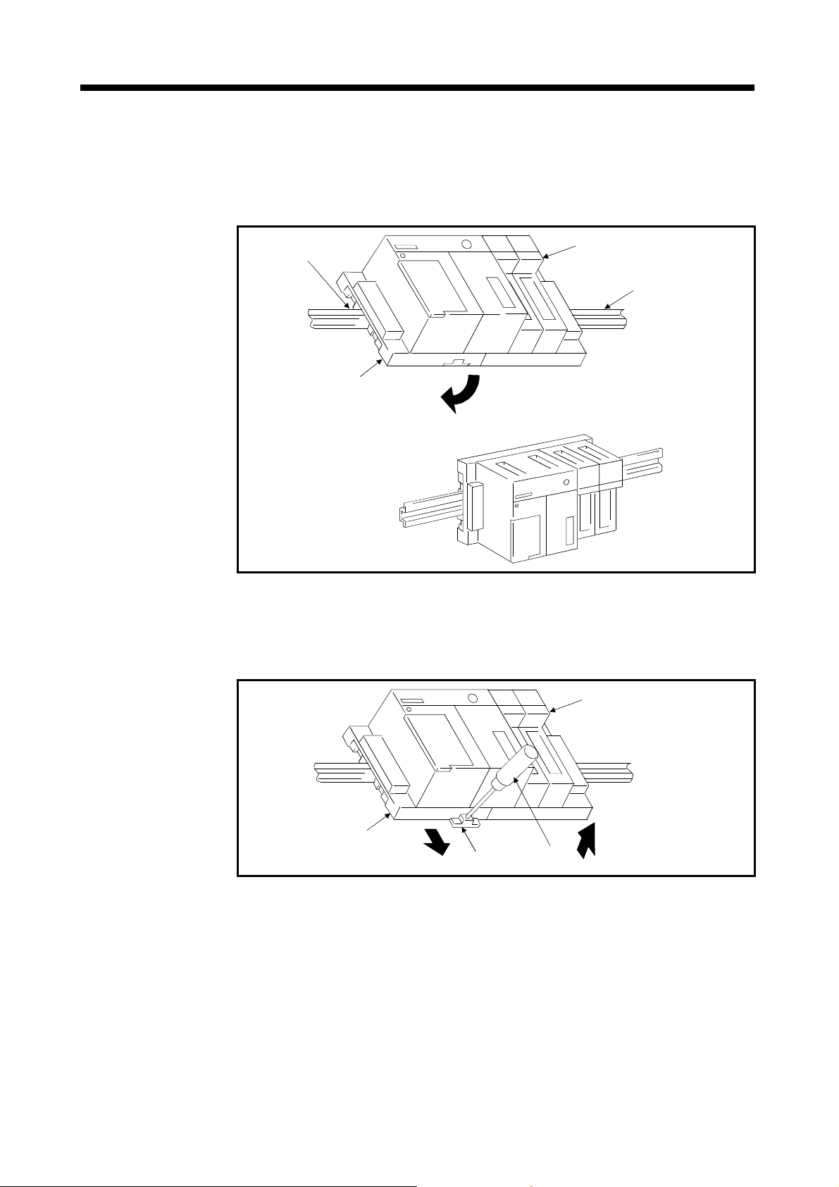
3. MOUNTING AND WIRING
t
(3) Mounting units to, and removing them from, the DIN rail
(a) Mounting to DIN rail
The procedure to mount a base unit on the DIN rail is described below.
1) Engage the top of the base unit DIN rail groove with the top of the DIN
rail.
2) Push the base unit toward the DIN rail to fasten it.
DIN rail groove
Base Unit
Modules
DIN rail
Fixed on the DIN rail.
(b) Removing from DIN rail
The procedure to remove a base unit from the DIN rail is described below.
1) Use a flat screwdriver to push down the hook under the base unit.
2) Pull the unit forward while pushing the hook down to remove the unit
from the DIN rail.
Base unit
Hook
Screwdriver
Modules
Direction to
remove the uni
3 − 3
Page 95

3. MOUNTING AND WIRING
s
3.3 Mounting and Removing Modules This section describes how to mount CPU modules, I/O modules, and special-
function modules in a base unit, and how to remove them.
(1) Mounting modules
Follow the procedure below to mount a module in the base unit.
Insert the two lugs on the rear panel of
the module into the module fixing
holes in the base unit.
Push the module in the direction of the
arrow to mount it in the base unit.
Ensure that the module is fully inserted
in the base unit and fasten the module
in position with the fastening screws.
End
Module fixing screw
Base unit
Module
Base unit
Module fixing holes
Module
Module
connector
Module lug
CAUTION
The lugs must be inserted in the module fixing holes when the module fixing screws are inserted.
Forcibly fixing a module in place with out ins ert ing the lugs in the ho les wil l bend the m odul e
connector pins and cause other damage.
Turn off the power supply before mounting or removing a module.
3 − 4
Page 96

3. MOUNTING AND WIRING
(2) Removing modules
Follow the procedure below to remove a module from the base unit.
Remove the fixing screws and pivot
the module around the bottom lugs
toward you.
Lifting the module up, detach the lugs
from the module fixing holes.
End
Base unit
Module
connector
Module
Module fixing
holes
(3) Fixing modules
When fixing the modules to the base unit, tighten the screws within the following
range.
Screw Tightening Torque Range N cm
Module mounting screw (M4 screw)
78 to 117
3 − 5
Page 97

3. MOUNTING AND WIRING
When removing a module, remove the module fixing screws before attempting to remove the
lugs from module fixing holes. Forcing out a module may damage the lugs.
Turn off the power supply before mounting or removing a module.
The terminal block and pin connectors of this base unit are made of resin. Do not drop them or
give them hard impact.
Do not remove the printed circuit boards of each module. Doing so can cause a failure.
Wire the cables carefully to ensure that no foreign matter such as wire-offcuts enter from the
module top. Remove them if any.
Tighten the module mounting and emergency stop input terminal screws within the tightening
torque ranges.
When fitting the module to the base, press the module against the base to ensure that the latch
is locked into the base. When removing the module, push the latch until the latch comes out of
the base completely, and pull the module toward you.
CAUTION
3 − 6
Page 98

3. MOUNTING AND WIRING
3.4 Mounting the Serial Absolute Synchronous Encoder Precautions when using a MR-HENC serial absolute synchronous encoder.
(1) If the serial absolute synchronous encoder is linked to a chain, timing belt, or
gears, the machine rotating shaft should be supported by a separate bearing
and connected to MR-HENC through a coupling. Ensure that excessive force
(greater than the permitted shaft load) is not applied to the encoder.
Gear
Bearing
Coupling
MR-HENC
Fig. 3.1 Example of Encoder Linked to a Gear
(2) Large errors in eccentricity and angle of deviation during mounting can apply
an excessive force to the MR-HENC shaft, which can cause deterioration in
performance drastically reduce encoder life.
Minimize loads applied to the shaft such that they lie within the permitted shaft
load range. The permitted shaft loads are shown in Fig. 3.2 for the
recommended coupling type.
Table 3.2 Permitted Values for Coupling Mounting Errors
Eccentricity
Table 3.1 Permitted Shaft Loads
Permitted shaft
load
0.2mm
(0.008 inch)
max.
Radial Direction Thrust Direction
98N max. 49N max.
Angle of deviation
Axial displacement
1.5° max.
0.5mm
(0.02 inch)
max.
3 − 7
Page 99

3. MOUNTING AND WIRING
The MR-HENC contains a glass disk and precision mechanism. Take care when handling it. The
encoder performance may deteriorate if it is dropped or subjected to shocks or vibration
exceeding the prescribed limits.
Do not connect the encoder directly to the rotating machine shaft. Always connect the encoder
through a flexible coupling.
CAUTION
Coupling
Rotating machine shaft
MR-HENC
Fig. 3.2 Connecting the Encoder to a Machine Shaft
Never hit the end o f th e MR -HE N C cou pl in g sha ft wi th a ha mmer w he n con ne cti ng th e co upl in g t o
it.
The large loads applied to MR-HENC will damage it.
The MR-HENC uses optical parts. Install it in an atmosphere where there are extremely few
water drops and little oil and dust.
In any place where the MR-HENC is exposed to water and/or oil, provide protection from oil and
water, e.g. install a cover. In addition, run the cable downward to prevent oil and/or water from
running on the cable into the MR-HENC. When it is inevitable to mount the MR-HENC vertically
or obliquely, trap the cable.
Use the MR-HENC within the specified temperature range (0C to 55C).
3 − 8
Page 100

3. MOUNTING AND WIRING
2
2
3.5 Wiring
3.5.1 How to Run the Power Supply and I/O Wires (1) Precautions when using the A1S62PN power supply module 24 VDC output
Do not connect 24 VDC outputs from multiple power supply modules in parallel
to supply a single I/O module. The power supply modules will be damaged if
the outputs are connected in parallel. If the 24 VDC output capacity of a single
power supply module is insufficient, supply power from an external 24 VDC
power supply.
CPU module
4VDC
4VDC
Power supply module
I/O
module
CPU module
24VDC
External power supply
(2) Twist 100 VAC, 200 VAC, and 24 VDC wires together as tightly as possible.
Connect units together over the minimum distance.
(3) To minimize the voltage drop, use the thickest 100 VAC, 200 VAC, and 24
VDC wires possible (2 mm
(4) Wiring the I/O equipment
(a) Wires between 0.75 mm
block, but 0.75 mm
2
max. ).
2
and 1.5 mm2 can be connected to the terminal
2
wires are recommended.
(b) If wires pass through a conduit, the conduit must be grounded.
I/O
module
CAUTION
Do not connect 24 VDC outputs from multiple power supply modules in parallel to supply a single
I/O module. This can damage or destroy the power supply modules.
Do not position the 100 VAC, 200 VAC or 24 VDC cables close to, or bundle them with, powercircuit (high-voltage, high-current) cables or I/O signal cables. A clearance of at least 100 mm
(3.94 in) to other cables is required.
3 − 9
 Loading...