

Page 1

35A-1
SERVICE BRAKES
CONTENTS
BASIC BRAKE SYSTEM 35A.........................................
ANTI-SKID BRAKING SYSTEM (ABS) <2WD> 35B......................
ANTI-SKID BRAKING SYSTEM (ABS) <4WD> 35C......................
NOTE
THE GROUPS MARKED BY ARE NOT IN THIS MANUAL
35109000159
Page 2

35A-2
BASIC BRAKE
SYSTEM
CONTENTS
GENERAL INFORMATION 3..................
SERVICE SPECIFICATIONS 4.................
LUBRICANTS 5..............................
SEALANTS 5................................
SPECIAL TOOLS 5..........................
ON-VEHICLE SERVICE 6.....................
Brake Pedal Check and Adjustment 6...........
Stop Lamp Switch Check 7.....................
Brake Booster Operating Test 7.................
Check Valve Operation Check 8.................
Proportioning Valve Function Test 9.............
Brake Fluid Level Sensor Check 9..............
Bleeding 10....................................
35109000302
Disc Brake Pad Check and Replacement 10.....
Disc Brake Rotor Check 12.....................
Brake Lining Thickness Check 14...............
Brake Drum Inside Diameter Check 14..........
Brake Lining and Brake Drum Connection
Check 14......................................
BRAKE PEDAL 15..........................
MASTER CYLINDER AND BRAKE
BOOSTER 16...............................
Master Cylinder 18.............................
DISC BRAKE 19............................
REAR DRUM BRAKE 24....................
Wheel Cylinder 26.............................
PROPORTIONING VALVE 28.................
Page 3

BASIC BRAKE SYSTEM -
General Information
35A-3
GENERAL INFORMATION
35100010182
The brake system offers high dependability and durability along with improved braking performance and
brake sensitivity.
Items Specifications
Master cylinder Type Tandem type (with level sensor)
I.D. mm 23.8
Brake booster Type Vacuum type, single
Effective dia. of power cylinder mm 230
Boosting ratio 6.0
Proportioning valve Type Dual type
Decompression ratio 0.25
Front brakes Type Floating caliper, 1-piston, ventilated disc
Disc effective dia.´thickness mm 256´24
Wheel cylinder I.D. mm 60.3
Pad thickness mm 10.0
Clearance adjustment Automatic
Rear disc brakes Type Floating caliper, 1-piston, solid disc
Disc effective dia.´thickness mm 262´24
Wheel cylinder I.D. mm 34.9
Pad thickness mm 10.0
Clearance adjustment Automatic
Rear drum brakes Type Leading trailing
Drum I.D. mm 203
Wheel cylinder I.D. mm 20.6
Lining thickness mm 4.4
Clearance adjustment Automatic
Brake fluid DOT3 or DOT4
Page 4
35A-4
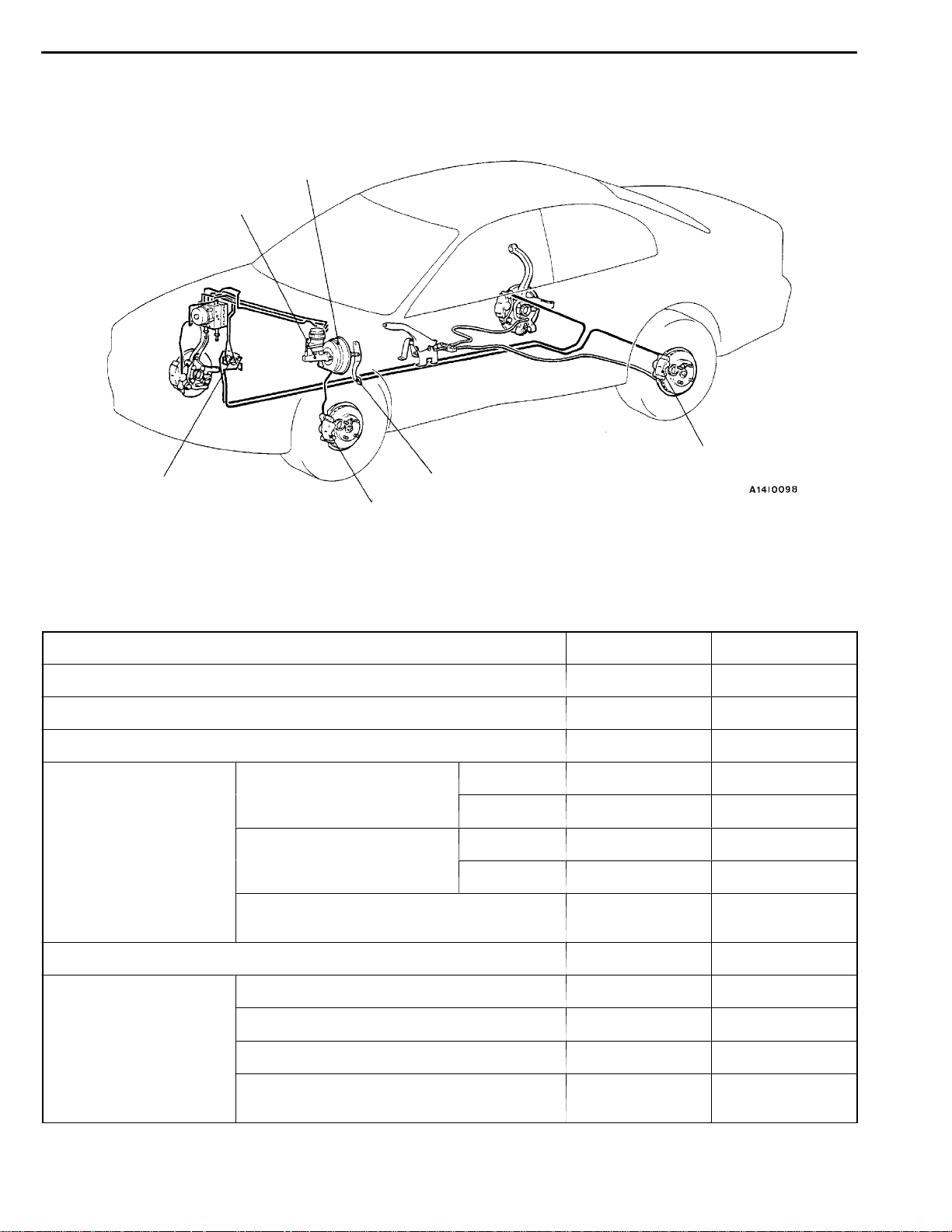
BASIC BRAKE SYSTEM -
CONSTRUCTION DIAGRAM
Brake booster
Master cylinder
General Information/
ServiceSpecifications
Rear brake
Proportioningvalve
Front brake
Brake pedal
SERVICE SPECIFICATIONS
Items Standard value Limit
Brake pedal height mm 162.8 - 165.8 Brake pedal free play mm 3-8 Brake pedal to floor board clearance mm 90 or more Proportioning valve Split point MPa Sedan 2.94±0.25 -
Wagon 3.43±0.25 -
Output fluid pressure Sedan 4.66±0.39 (9.81) (Input fluid pressure) MPa
Wagon 5.80±0.39 (9.81) -
Output fluid pressure difference between left
and right MPa
- 0.39
35100030201
Brake booster push rod protruding length mm 9.65 -9.90 Front disc brake Pad thickness mm 10.0 2.0
Disc thickness mm 24.0 22.4
Disc runout mm - 0.06
Dragforce (tangential forceof wheelmounting
bolts) N
69 or less -
Page 5
Service Specifications/Lubricants/
BASIC BRAKE SYSTEM -
Items Standard value Limit
Rear disc brake Pad thickness mm 10.0 2.0
Disc thickness mm 10.0 8.4
Disc runout mm - 0.08
Sealants/Special Tools
35A-5
Drag force (tangential force of wheel mounting
bolts) N
Rear drum brake Lining thickness mm 4.4 1.0
Drum inside diameter mm 203 205
69 or less -
LUBRICANTS
Items Specified Lubricant
Brake fluid DOT3 or DOT4
Brake piston seal Repair kit grease (orange)
Slide pin boot and slide pin bush inner surfaces
Brake piston boot inner surfaces
Piston boot mounting grooves
Rear brake shoe and backing plate contact surfaces Brake grease SAE J310, NLGI No.1
Shoe assembly and auto adjuster assembly contact
surfaces
Shoe and lever assembly and auto adjuster assembly
contact surfaces
35100040082
SEALANTS
Items Specified sealant Remarks
Thread part fitting 3M ATD Part No. 8661 or equivalent Semi-drying sealant
V acuum switch
SPECIAL TOOLS
Tool Number Name Use
MB990964
MB990520
MB990619
MB990998 Front hub remover
Brake tool set D Pushing-in of the disc brake piston
D Installation of drum brake wheel cylinder
piston cup
Provisional holding of the wheel bearing
and installer
35100050153
35100060071
Page 6
35A-6
BASIC BRAKE SYSTEM -
On-vehicle Service
Operating
rod
Operating
rod lock nut
Pedal down
Pedal up
Lock nut
Stop lamp
switch
Lock nut
Outer case
0.5 - 1.0 mm
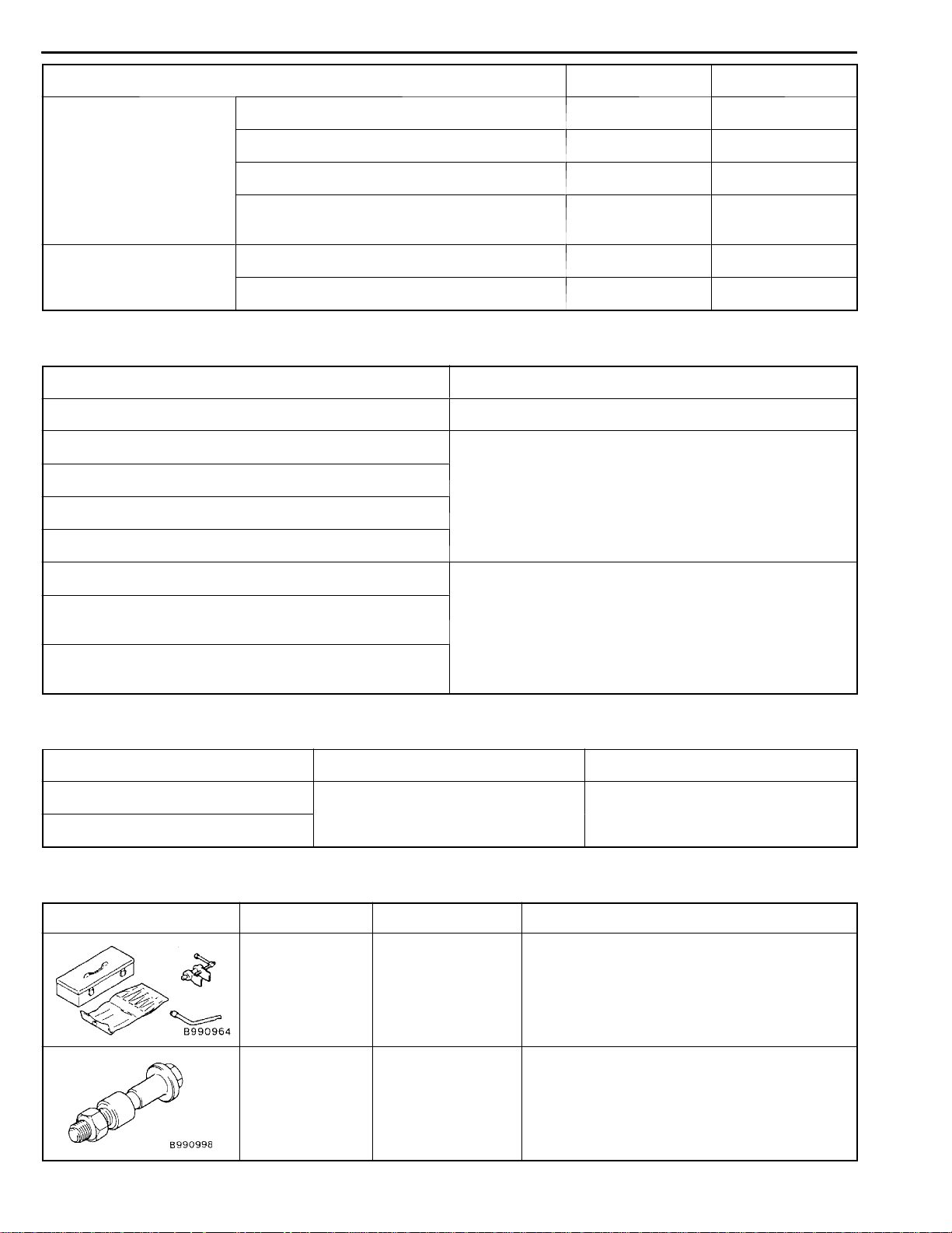
ON-VEHICLE SERVICE
35100090186
BRAKE PEDAL CHECK AND ADJUSTMENT
BRAKE PEDAL HEIGHT
1. Turn up the carpet, etc under the brake pedal.
2. Measure the brake pedal height as illustrated. If the brake
pedal height is not within the standard value, follow the
procedure below.
Standard value: 162.8 - 165.8 mm
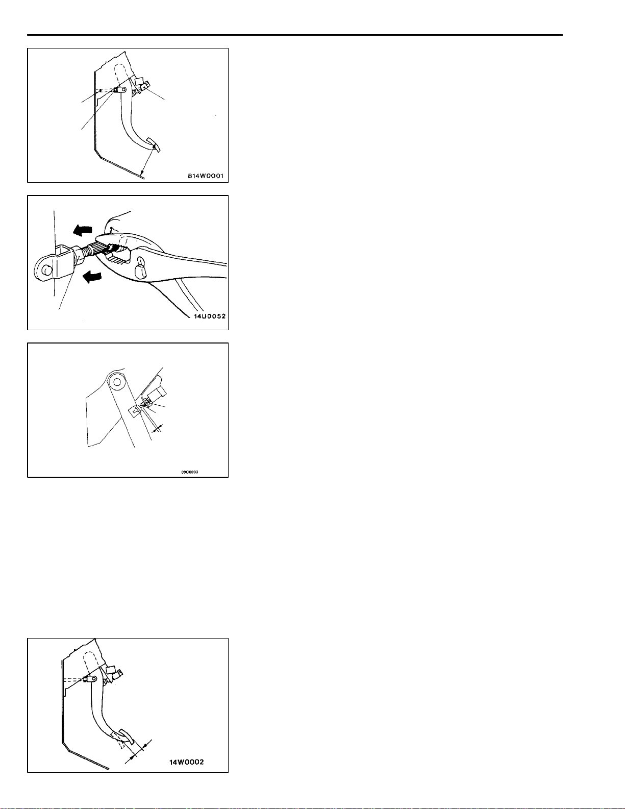
(1) Disconnect the stop lamp switch connector.
(2) Adjust the brake pedal height by turning the operating
rod with pliers (with the operating rod lock nut
loosened), until the correct brake pedal height is
obtained.
(3) Secure by tightening the lock nut of the operating
rod.
(4) Push the stop lamp switch in the direction of the
pedal stroke until it stops. (The switch will slide if
it is pushed firmly.)
(5) Lift up the pedal until the operating rod is fully
extended, and then slide the stop lamp switch back
to the required position. Adjust the position of the
switch by turning it until the distance shown in the
illustration is correct.
(6) Connect the connector of the stop lamp switch.
(7) Check that the stop lamp is not illuminated with the
brake pedal unpressed.
3. Return the carpet etc.
BRAKE PEDAL FREE PLAY
With the engine stopped, depress the brake pedal two or
three times. After eliminating the vacuum in the power brake
booster, press the pedal down by hand, and confirm that
the amount of movement before resistance is met (the free
play) is within the standard value range.
Page 7
BASIC BRAKE SYSTEM -
Standard value: 3–8 mm
If the free play exceeds the standard value, it is probably
due to excessive play between the retaining ring bolt and
brake pedal arm.
Check for excessive clearance and replace faulty parts as
required.
CLEARANCE BETWEEN BRAKE PEDAL AND FLOOR
BOARD
1. Turn back the carpet etc. under the brake pedal.
2. Start the engine, depress the brake pedal with
approximately 490 N of force, and measure the clearance
between the brake pedal and the floorboard.
Standard value: 90 mm or more
3. If the clearance is outside the standard value, check for
air trapped in the brake line, clearance between the lining
and the drum and dragging in the parking brake.
Adjust and replace defective parts as required.
On-vehicle Service
35A-7
No continuity
Good No good
Continuity
4mm
4. Return the carpet etc.
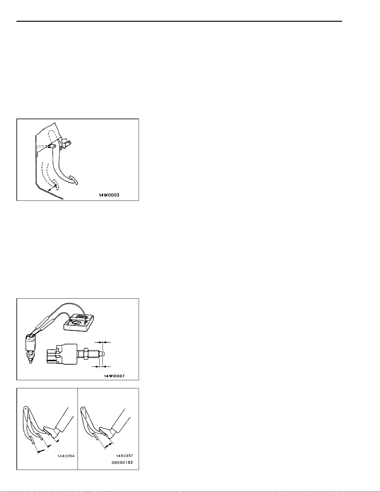
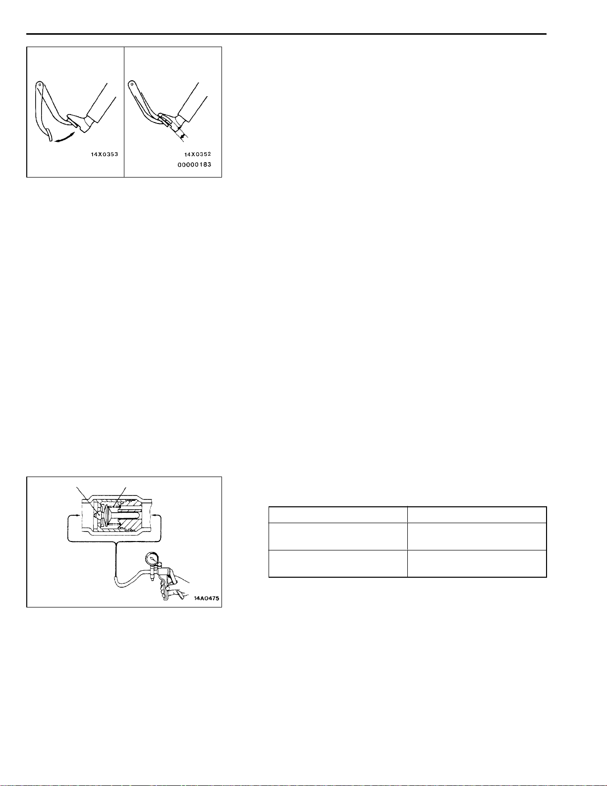
STOP LAMP SWITCH CHECK
35100890120
Connect a circuit tester to the stop lamp switch, and check
whether or not there is continuity when the plunger of the
stop lamp switch is pushed in and when it is released. The
stop lamp switch is in good condition if there is no continuity
when the plunger is pushed in to a depth of within 4 mm
from the outer case edge surface, and if there is continuity
when it is released.
BRAKE BOOSTER OPERATING TEST
35100100117
For simple checking of the brake booster operation, carry
out the following tests:
1. Run the engine for one or two minutes, and then stop
it.
If the pedal depresses fully the first time but gradually
becomes higher when depressed succeeding times, the
booster is operating properly, if the pedal height remains
unchanged, the booster is defective.
Page 8
35A-8
BASIC BRAKE SYSTEM -
On-vehicle Service
When engine is
stopped
When engine is
started
2. With the engine stopped, step on the brake pedal several
times.
Then step on the brake pedal and start the engine.
If the pedal moves downward slightly, the booster is in
good condition. If there is no change, the booster is
defective.
3. With the engine running, step on the brake pedal and
then stop the engine.
Hold the pedal depressed for 30 seconds. If the pedal
height does not change, the booster is in good condition,
if the pedal rises, the booster is defective.
If the above three tests are okay, the booster performance
can be determined as good.
If one of the above three tests is not okay at last, the
check valve, vacuum hose, or booster will be defective.
Valve
Booster
side
Spring
AB
Intake
manifold
side
CHECK VALVE OPERATION CHECK
35100900151
1. Remove the vacuum hose. (Refer to P.35A-16.)
Caution
The check valve should not be removed from the
vacuum hose.
2. Check the operation of the check valve by using a vacuum
pump.
V acuum pump connection Accept/reject criteria
Connection at the brake
booster side (A)
Connection at the intake
manifold side (B)
A negative pressure (vacuum) is created and held.
A negative pressure (vacuum) is not created.
Caution
If the check valve is defective, replace it as an
assembly unit together with the vacuum hose.
Page 9
BASIC BRAKE SYSTEM -
On-vehicle Service
35A-9
Output
pressure
Pressure gauge
Proportioning valve
Split point
Input pressure
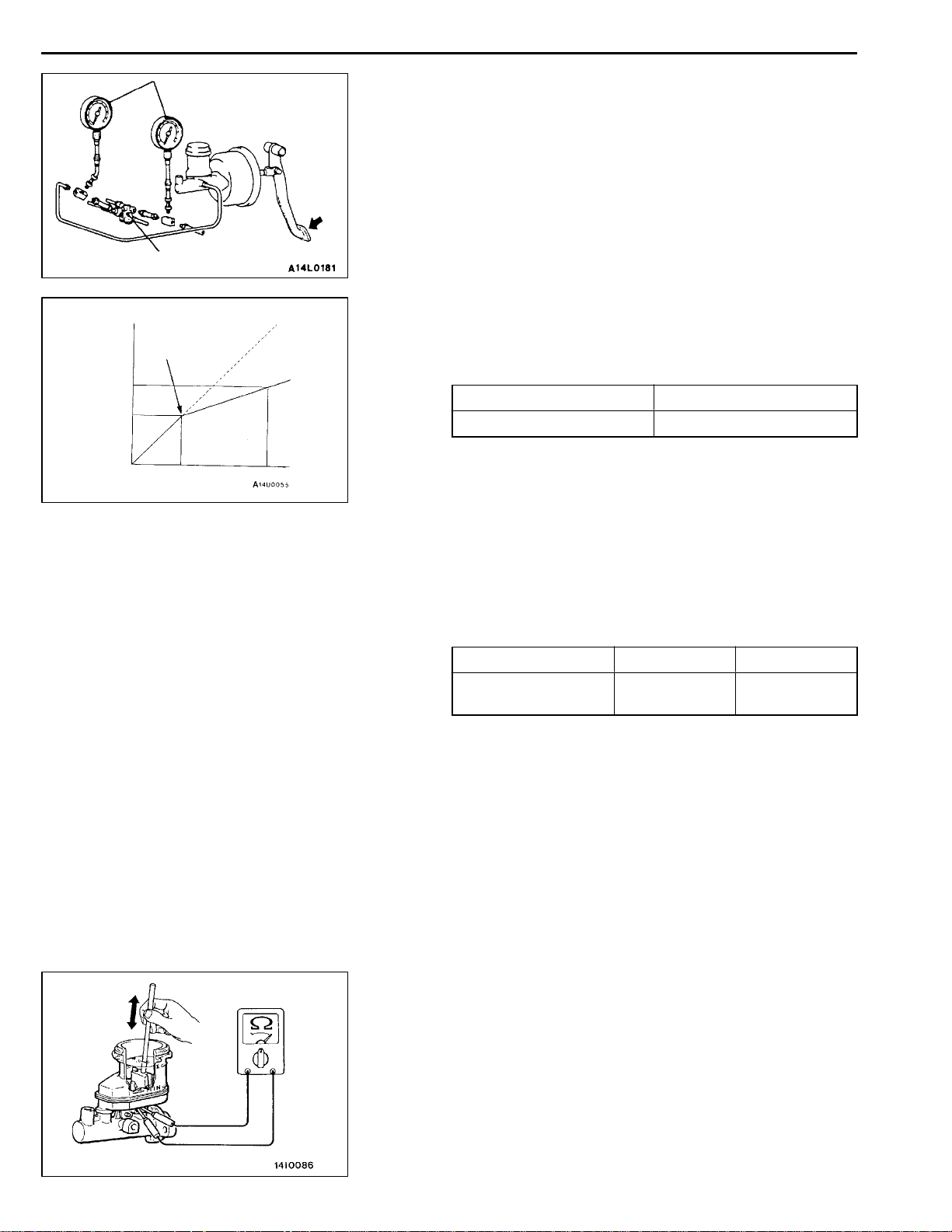
PROPORTIONING VALVE FUNCTION TEST
35100110172
1. Connect two pressure gauges, one each to the input
side and output side of the proportioning valve, as shown.
2. Bleed the air in the brake line and the pressure gauge.
3. While gradually depressing the brake pedal, make the
following measurements and check to be sure that the
measured values are within the allowable range.
(1) Output pressure begins to drop relative to input
pressure (split point).
Standard value:
MPa
Sedan Wagon
2.94±0.25 3.43±0.25
(2) Check to be sure that the output fluid pressure is
at the standard value when the pedal depression
force is increased so that the input fluid pressure
is at the values shown in the table below.
Standard value:
MPa
Sedan Wagon
Output fluid pressure
(Input fluid pressure)
4.66±0.39
(9.81)
5.80±0.39
(9.81)
(3) Output pressure difference between left and right
brake lines.
Limit: 0.39 MPa
4. If the measured pressures are not within the permissible
ranges, replace the proportioning valve.
BRAKE FLUID LEVEL SENSOR CHECK
35100910123
The brake fluid level sensor is in good condition if there is
no continuity when the float surface is above “MIN” and if
there is continuity when the float surface is below “MIN”.
Page 10
35A-10
BASIC BRAKE SYSTEM -
On-vehicle Service
BLEEDING
35100140089
Caution
Use the specified brake fluid. Avoid using a mixture of
the specified brake fluid and other fluid.
Specified brake fluid: DOT3 or DOT4
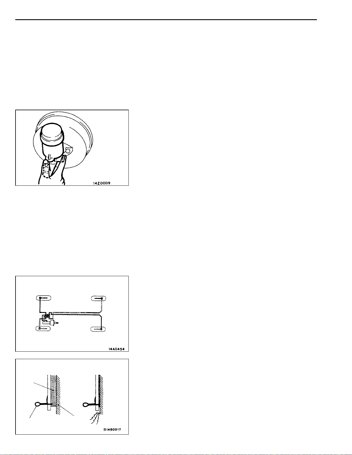
MASTER CYLINDER BLEEDING
The master cylinder used has no check valve, so if bleeding
is carried out by the following procedure, bleeding of air from
the brake pipeline will become easier. (When brake fluid is
not contained in the master cylinder.)
(1) Fill the reserve tank with brake fluid.
(2) Keep the brake pedal depressed.
(3) Have another person cover the master cylinder outlet
with a finger.
(4) With the outlet still closed, release the brake pedal.
(5) Repeat steps (2)- (4) three or four times to fill the inside
of the master cylinder with brake fluid.
4 (2)
2 (4)
( ): R.H. drive vehicles
When new When worn
Pad
Wear indicator
Brake disc
1 (3)
3 (1)
BRAKE PIPE LINE BLEEDING
Bleed the air in the sequence shown in the figure.
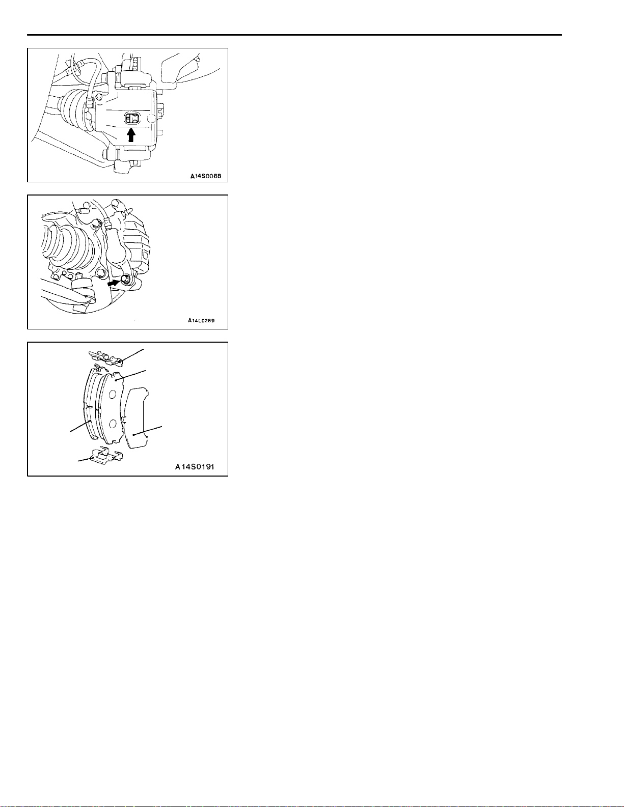
DISC BRAKE PAD CHECK AND
REPLACEMENT
NOTE
The left side outer brake pad has a wear indicator.
The wear indicator contacts the brake disc when the brake
pad thickness becomes 2 mm and emit a squealing sound
to warn the driver.
35100230014
Page 11
BASIC BRAKE SYSTEM -
1. Check brake pad thickness through caliper body check
port.
Standard value: 10 mm
Limit: 2.0 mm
Caution
1. When the limit is exceeded, replace the pads at
both sides, and also the brake pads for the wheels
on the opposite side at the same time.
2. If there is a significant difference in the thickness
of the pads on the left and right sides, check the
sliding condition of the piston and guide pin.
2. Remove the guide pin. Lift caliper assembly and retain
with wires.
Caution
Do not wipe off the special grease that is on the guide
pin or allow it to contaminate the guide pin.
On-vehicle Service
35A-11
3
2
1
3
4
3. Remove the following parts from caliper support.
(1) Pad and wear indicator assembly <L.H.>, and pad
assembly <R.H.>
(2) Pad assembly
(3) Pad liner
(4) Outer shim
4. In order to measure the brake drag force after pad
installation, measure the rotary-sliding resistance of the
hub with the pads removed. (Refer to P.35A-19.)
5. Install the pads and the caliper assembly, and then check
the brake drag force. (Refer to P.35A-19.)
Page 12
35A-12
BASIC BRAKE SYSTEM -
On-vehicle Service
DISC BRAKE ROTOR CHECK
35100290012
Caution
When servicing disc brakes, it is necessary to exercise caution to keep the disc brakes within
the allowable service values in order to maintain normal brake operation.
Before re-finishing or re-processing the brake disc surface, the following conditions should be checked.
Inspection items Remarks
D
Scratches, rust, saturated lining materials
and wear
Run-out or drift Excessive run-out or drift of the discs will increase the pedal depression
Change in thickness (parallelism) If the thickness of the disc changes, this will cause pedal pulsation,
Inset or warping (flatness) Overheating and improper handling while servicing will cause inset or
If the vehicle is not driven for a certain period, the sections of
the discs that are not in contact with lining will become rusty, causing
noise and shuddering.
D
If grooves resulting from excessive disc wear and scratches are
not removed prior to installing a new pad assembly, there will
momentarily be inappropriate contact between the disc and the
lining (pad).
resistance due to piston knock-back.
shuddering and surging.
warping.
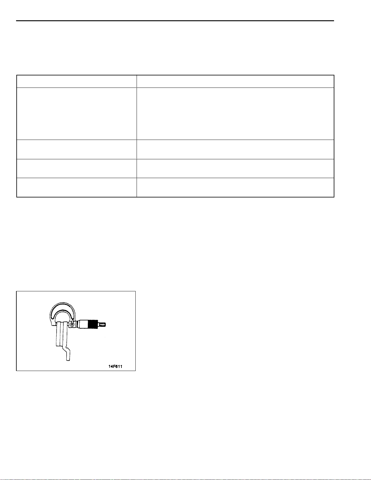
THICKNESS CHECK
35100240017
1. Using a micrometer, measure disc thickness at eight
positions, approximately 45_apart and 10 mm in from
the outer edge of the disc.
Brake disc thickness
Standardvalue: 24.0 mm <Front>, 10.0 mm<Rear>
Limit: 22.4 mm <Front>, 8.4 mm <Rear>
Thickness variation (at least 8 positions)
The difference between any thickness measurements
should not be more than 0.015 mm.
2. If the disc is beyond the limits for thickness, remove it
and install a new one. If thickness variation exceeds the
specification, replace the brake disc or turn rotor with
on the car type brake lathe (“MAD, DL-8700PF” or
equivalent).
Page 13
BASIC BRAKE SYSTEM -
On-vehicle Service
35A-13
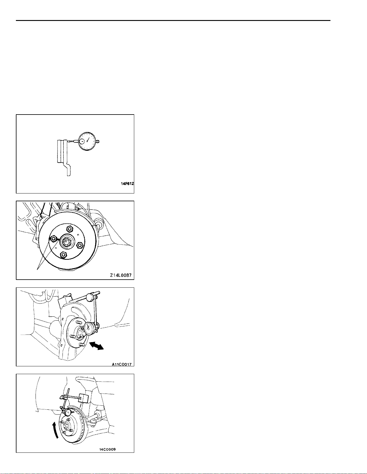
RUN-OUT CHECK
35100250010
1. Remove the caliper support; then raise the caliper
assembly upward and secure by using wire.
2. Inspect the disc surface for grooves, cracks and rust.
Clean the disc thoroughly and remove all rust.
3. Place a dial gauge approximately 5 mm from the outer
circumference of the brake disc, and measure the run-out
of the disc.
Limit:
0.06 mm or less <Front>
0.08 mm or less <Rear>
NOTE
Tighten the nuts in order to secure the disc to the hub.
RUN-OUT CORRECTION
35100180081
1. If the run-out of the brake disc is equivalent to or exceeds
the limit specification, change the phase of the disc and
hub, and then measure the run-out again.
(1) Before removing the brake disc, chalk both sides
of the wheel stud on the side at which run-out is
greatest.
Chalk mark
(2) Remove the brake disc, and then place a dial gauge
as shown in the illustration; then move the hub in
the axial direction and measure the play.
Limit: 0.05 mm
If the play is equivalent to or exceeds the limit,
disassemble the hub knuckle and check each part.
(3) If the play does not exceed th e limit specification,
install the brake disc at a position 180_ away from
the chalk mark, and then check the run-out of the
brake disc once again.
2. If the run-out cannot be corrected by changing the phase
of the brake disc, replace the disc or turn rotor with on
the car type brake lathe (“MAD, DL-8700PF” or
equivalent).
Page 14
35A-14
BASIC BRAKE SYSTEM -
On-vehicle Service
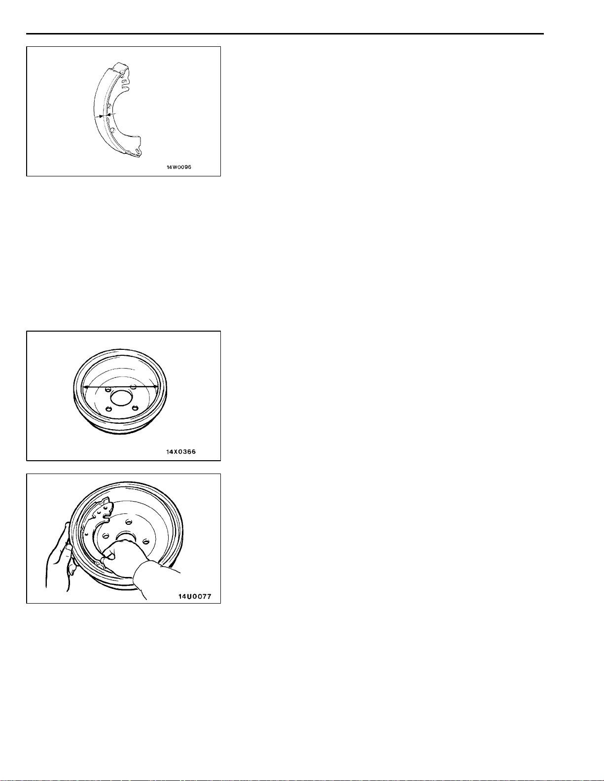
BRAKE LINING THICKNESS CHECK
1. Remove the brake drum.
2. Measure the wear of the brake lining at the place worn
the most.
Standard value: 4.4 mm
Limit: 1.0 mm
Replace the shoe and lining assembly if brake lining
thickness is less than the limit or if it is not worn evenly.
For information concerning the procedures for installation
of the shoe and lining assembly, refer to P.35A-24.
Caution
1. Whenever the shoe and lining assembly is
replaced, replace both R.H. and L.H. assemblies
as a set to prevent car from pulling to one side
when braking.
2. If there is a significant difference in the thickness
of the shoe and lining assemblies on the left and
right sides, check the sliding condition of the
piston.
35100300166
BRAKE DRUM INSIDE DIAMETER CHECK
35100320148
1. Remove the brake drum.
2. Measure the inside diameter of t he brake drum at two
or more locations.
Standard value: 203 mm
Limit: 205 mm
3. Replace brake drums, shoe and lining assembly when
wear exceeds the limit value or is badly imbalanced.
BRAKE LINING AND BRAKE DRUM
CONNECTION CHECK
1. Remove the brake drum.
2. Remove the shoe and lining assembly.
(Refer to P.35A-24.)
3. Chalk inner surface of brake drum and rub with shoe
and lining assembly.
4. Replace shoe and lining assembly or brake drums if there
are any irregular contact area.
NOTE
Clean off chalk after check.
35100310169
Page 15
BASIC BRAKE SYSTEM -
Brake Pedal
35A-15
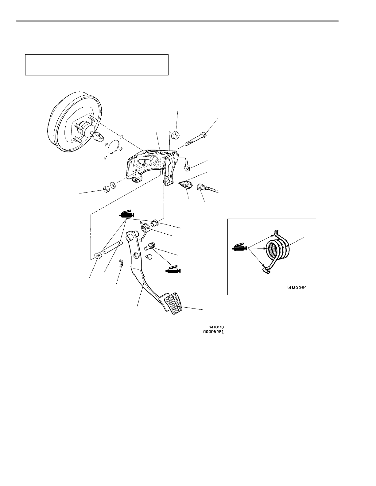
BRAKE PEDAL
REMOVAL AND INSTALLATION
Post-installation Operation
Brake Pedal Adjustment (Refer to P.35A-6.)
29 Nm
11
14 Nm
35100340243
5
12 Nm
13 Nm
2
1
10
9
3
6
Removal steps
1. Stop lamp switch connector
2. Stop lamp switch
3. Snap pin
4. Pin assembly
5. Brake pedal shaft bolt
6. Brake pedal
9
8
8
4
7
7. Brake pedal pad
8. Brake pedal return spring
9. Bushing
10. Pipe
11. Pedal support member
Page 16
35A-16
BASIC BRAKE SYSTEM -
Master Cylinder and Brake Booster
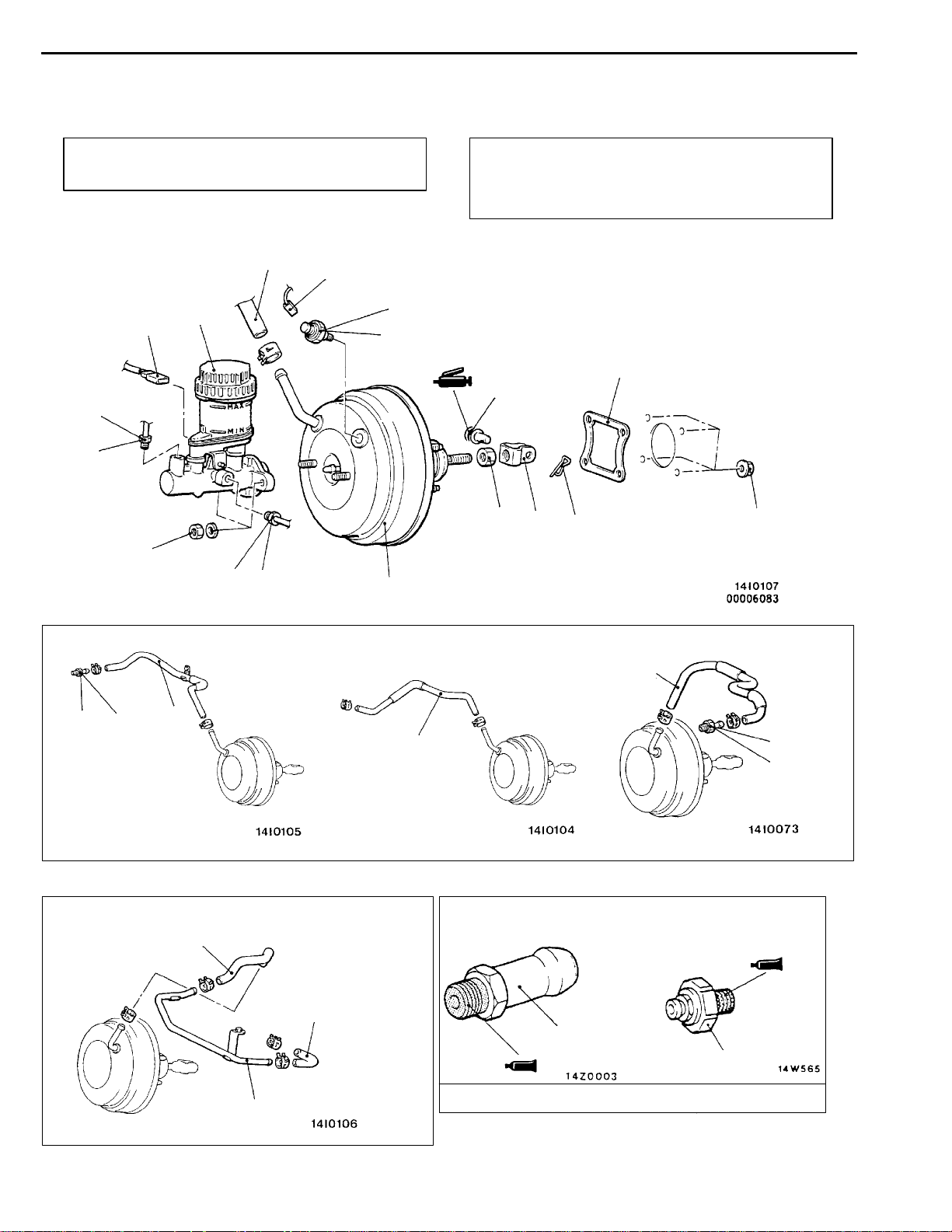
MASTER CYLINDER AND BRAKE BOOSTER
REMOVAL AND INSTALLATION
Pre-removal Operation
Brake Fluid Draining
2
15 Nm
1
6
3
11
12
20 - 25 Nm
Post-installation Operation
D Brake Fluid Supplying
D Brake Line Bleeding (Refer to P.35A-10.)
D Brake Pedal Adjustment (Refer to P.35A-6.)
9
22 Nm
10
8
35100370242
14
14 Nm
10 Nm
15 Nm
1
<L.H. drive vehicles - 4G6,6A1>
7
15 Nm
<R.H. drive vehicles - 4D6>
6
4
13
<L.H. drive vehicles - 4D6>
4
<R.H. drive vehicles - 4G6,6A1>
6
7
15 Nm
4
7
12
5
Sealant: 3M ATD Part No.8661 or equivalent
Page 17
BASIC BRAKE SYSTEM -
Removal steps
1. Brake pipe connection
2. Brake fluid level sensor connector
3. Master cylinder assembly
"BADPush rod protruding length check and
adjustment
4. Vacuum hose <4D6>
5. Vacuum pipe <4D6>
"AA 6. Vacuum hose
(with built-in check valve)
INSTALLATION SERVICE POINTS
"AA
Insert securely and completely until the vacuum hose at the
engine side contacts the edge of the hexagonal part of the
fitting, and then secure by using the hose clip.
Master Cylinder and Brake Booster
7. Fitting
8. Snap pin
9. Pin assembly
10. Clevis
11. Vacuum switch connector <4D6>
12. Vacuum switch <4D6>
13. Brake booster
14. Sealer
VACUUM HOSE CONNECTION
35A-17
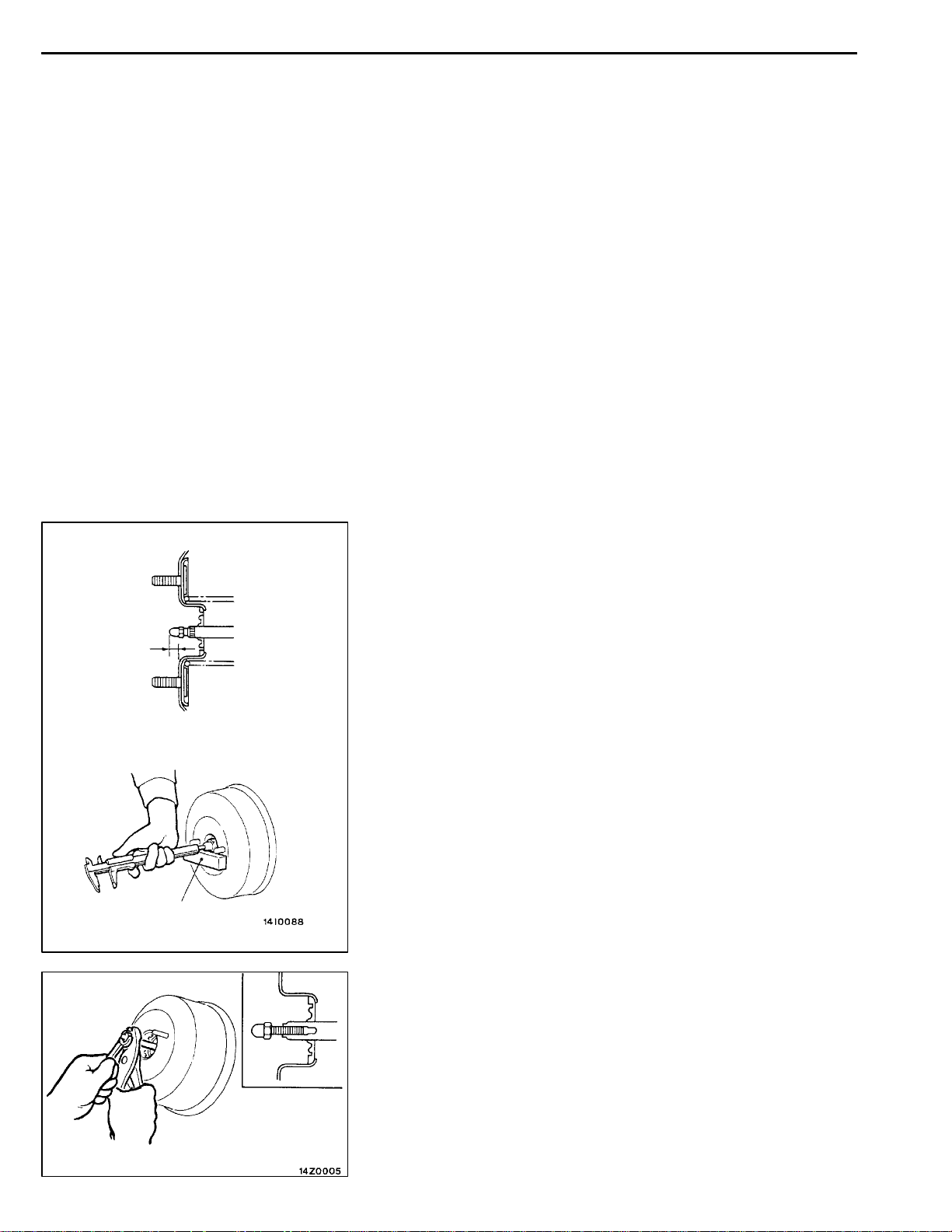
A
Measuring dimension A
Block gauge
"BA
PUSH ROD PROTRUDING LENGTH CHECK AND
ADJUSTMENT
1. Measure dimension A.
Standard value: 9.65 - 9.90 mm
2. If the protruding length is not within the standard value
range, adjust by changing the push rod length by turning
the end of the push rod.
Page 18
35A-18
BASIC BRAKE SYSTEM -
Master Cylinder and Brake Booster
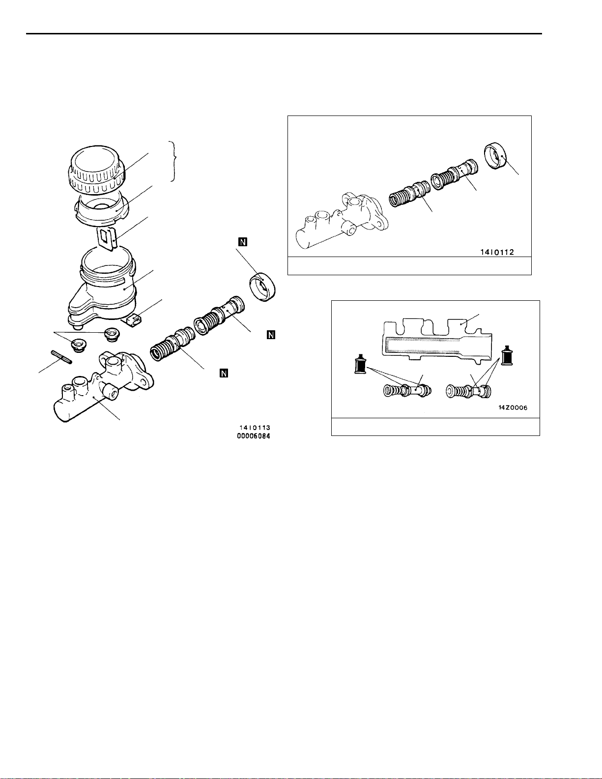
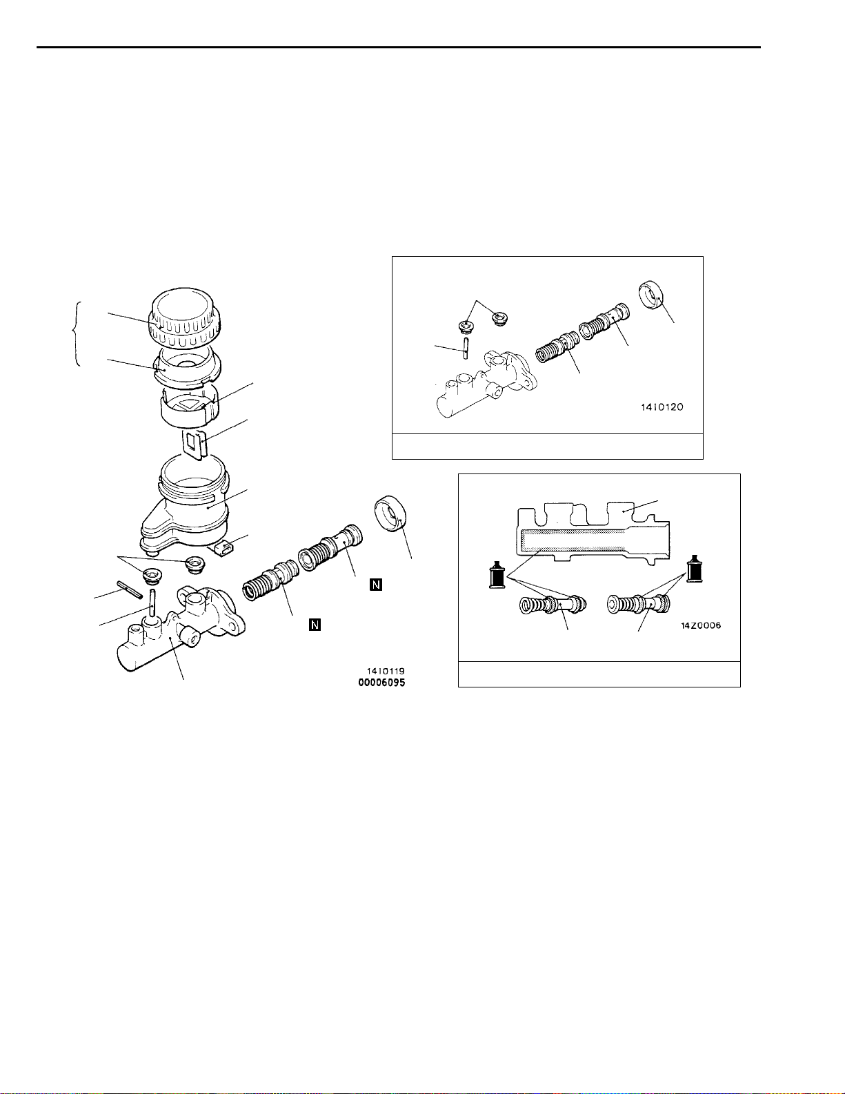
MASTER CYLINDER
DISASSEMBLY AND REASSEMBLY
2
5
8
1
3
9
7
4
35100420145
9
10
11
Master cylinder kit
12
10
6
12
Disassembly steps
1. Reservoir cap assembly
2. Reservoir cap
3. Diaphragm
4. Brake fluid level indicator assembly
5. Float
6. Spring pin
11
Brake fluid: DOT3 or DOT4
7. Reservoir tank
8. Reservoir seal
9. Piston retainer
10. Primary piston assembly
11. Secondary piston assembly
12. Master cylinder body
11
10
Page 19

BASIC BRAKE SYSTEM -
Disc Brake
35A-19
DISC BRAKE
REMOVAL AND INSTALLATION
Pre-removal Operation
Brake Fluid Draining
<Front>
90 - 110 Nm
29 Nm
1
2
3
<Rear>
Post-installation Operation
D Brake Fluid Supplying
D Brake Line Bleeding (Refer to P.35A-10.)
4
1
3
35100800017
Removal steps
1. Brake hose connection
2. Gasket
MB990998
Tighten the nut with
the bolt secured.
Bolt
29 Nm
2
55 - 65 Nm
"AA
3. Disc brake assembly
4. Brake disc
INSTALLATION SERVICE POIINT
"AA
1. In order to measure the brake drag torque after pad
DISC BRAKE ASSEMBLY INSTALLATION
installtion, measure the rotary-sliding resistance of the
hub by the following procedure with the pads removed.
<Front>
(1) Remove the drive shaft.
(Refer to GROUP 26 - Front Axle.)
4
Page 20

35A-20
BASIC BRAKE SYSTEM -
(2) Attach the special tool to the front hub assembly as
shown in the illustration, and tighten it to the specified
torque.
Tightening torque: 196 - 255 Nm
(3) Use a spring balance to measure the rotary-sliding
resistance of the hub in the forward direction.
<Rear>
Use a spring balance to measure the rotary-sliding
resistance of the hub in the forward direction.
Disc Brake
MB990520
2. After installing the caliper support to the knuckle, install
the pad clips and the pads to the caliper support.
Caution
Do not let any oil, grease or other contamination get
onto the friction surfaces of the pads and brake discs.
3. Clean piston and insert into cylinder with special tool.
4. Be careful that the piston boot does not become caught
when lowering the caliper assembly, and tighten the guide
pin to the specified torque.
Tightening torque: 74 Nm
5. Start the engine and then depress the brake pedal 2 -3
times.
6. Stop engine.
7. Turn brake disc forward 10 times.
8. Use a spring balance to measure the rotation sliding
resistance of the hub in the forward direction.
9. Calculate the drag force of the disc brake (difference
between of values measured in item 8 and item 1.)
Standard value: 69 N or less
10. If the drag force of the disc brake exceeds the standard
value, disassemble piston and clean piston. Check for
corrosion or worn piston seal, and check the sliding
condition of the lock pin and guide pin.
Page 21

BASIC BRAKE SYSTEM -
Disc Brake
35A-21
DISASSEMBLY AND REASSEMBLY
2
74 Nm
8Nm
1
74 Nm
3
5
11
35100820013
14
12
13
14
10
9
5
8
4
7
6
3
5
2
1
10
5
9
6
8
4
7
13
12
11
14
Brake caliper kit Pad repair kit Seal and boots repair kit
Caliper assembly disassembly
steps
"AA
"AA
AA"
AA"
AB"
1. Guide pin
2. Lock pin
3. Bushing
4. Caliper support (pad, clip, shim)
5. Boot
6. Boot ring
7. Piston boot
8. Piston
9. Piston seal
10. Caliper body
14
11
14
"AA
"AA
14
9
3
5
Grease
13
7
5
6
12
Pad assembly disassembly steps
1. Guide pin
2. Lock pin
3. Bushing
4. Caliper support (pad, clip, shim)
11. Pad and wear indicator assembly
12. Pad assembly
13. Outer shim (coated with rubber)
14. Clip
Page 22

35A-22
LUBRICATION POINTS
Piston
seal
BASIC BRAKE SYSTEM -
Disc Brake
Grease: Repair kit grease
Caution
The piston seal inside the seal
and boot kit is coated with
special grease, so do not wipe
this grease off.
Brake fluid: DOT3 or DOT4
Grease: Repair kit grease
Grease: Repair kit grease
DISASSEMBLY SERVICE POINTS
When disassembling the disc brakes, disassemble both sides
(left and right) as a set.
Page 23

BASIC BRAKE SYSTEM -
Disc Brake
35A-23
AA"
PISTON BOOT/PISTON REMOVAL
Protect caliper body with cloth. Blow compressed air through
brake hose to remove piston boot and piston.
Caution
Blow compressed air gently.
AB"
PISTON SEAL REMOVAL
1. Remove piston seal with finger tip.
Caution
Do not use a flat-tipped screwdriver or other tool to
prevent damage to inner cylinder.
2. Clean piston surface and inner cylinder with
trichloroethylene, alcohol or specified brake fluid.
Specified brake fluid: DOT3 or DOT4
Front
Guide pin
“G”
Lock pin
“L”
REASSEMBLY SERVICE POINT
"AA
Install the guide pin and lock pin as illustrated that each
head mark of the guide pin and the lock pin matches the
indication mark (“G” or “L”) located on the caliper body.
INSPECTION
D Check cylinder for wear, damage or rust.
D Check piston surface for wear, damage or rust.
D Check caliper body or sleeve for wear.
D Check pad for damage or adhesion of grease, check
LOCK PIN/GUIDE PIN INSTALLATION
35100630081
backing metal for damage.
Page 24

35A-24
BASIC BRAKE SYSTEM -
Rear Drum Brake
REAR DRUM BRAKE
REMOVAL AND INSTALLATION
Pre-removal Operation
D Loosening the Parking Brake Cable Adjusting Nut.
D Brake Fluid Draining
15 Nm
74 - 88 Nm
17
16
16
20
35100750145
Post-installation Operation
D Brake Line Bleeding (Refer to P.35A-10.)
D Parking Brake Lever Stroke Adjustment
(Refer to GROUP 36 – On-vehicle Service.)
11
12
13
3
5
14
15
4
19
9
1
10
18
8
6
7
8
2
5
10
4
5
15
Specified grease: Brake grease SAE J310, NLGI No.1
Removal steps
1. Brake drum
2. Lever return spring
3. Shoe-to-lever spring
4. Adjuster lever
5. Auto adjuster assembly
6. Retainer spring
7. Shoe hold-down cup
8. Shoe hold-down spring
9. Shoe-to-shoe spring
10. Shoe and lining assembly
AA""BA
7
"AA
20
11. Shoe and lever assembly
12. Retainer
13. Wave washer
14. Parking lever
15. Shoe and lining assembly
16. Shoe hold-down pin
17. Brake pipe connection
18. Snap ring
19. Rear hub assembly
20. Backing plate
Page 25

Pin of shoe assembly
Retainer
Washer
Parking lever
BASIC BRAKE SYSTEM -
REMOVAL SERVICE POINT
AA"
Use a flat-tipped screwdriver or the like to open up the retainer
joint, and remove retainer.
RETAINER REMOVAL
INSTALLATION SERVICE POINTS
Shoe assembly
Pin
"AA
Install the washer in the direction shown in the illustration.
WAVE WASHER INSTALLATION
Rear Drum Brake
35A-25
Pin of shoe assembly
Retainer
"BA
RETAINER INSTALLATION
Use pliers or the like to install the retainer or the pin positively.
Page 26

35A-26
BASIC BRAKE SYSTEM -
Rear Drum Brake
WHEEL CYLINDER
REMOVAL AND INSTALLATION
Pre-removal Operation
Brake Fluid draining
15 Nm
5
10 Nm
35100930082
Post-installation Operation
D Brake Fluid Supplying
D Brake Line Bleeding (Refer to P.35A-10.)
3
2
4
8Nm
7
6
1
Removal steps
1. Brake drum
2. Shoe-to-lever spring
3. Shoe-to-shoe spring
4. Auto adjuster assembly
5. Brake pipe connection
6. Wheel cylinder
7. Bleeder screw
Page 27
BASIC BRAKE SYSTEM -
Rear Drum Brake
35A-27
DISASSEMBLY AND REASSEMBLY
3
Grease: Repair kit grease
1
34
6
6
2
3
Brake fluid: DOT3 or DOT4
2
5
4
3
1
35100770097
6
4
1
4
Grease
"AA
MB990619
Disassembly steps
1. Boots
2. Piston assembly
3. Pistons
Piston
Wheel cylinder repair kit
"AA
4. Piston cups
5. Spring
6. Wheel cylinder body
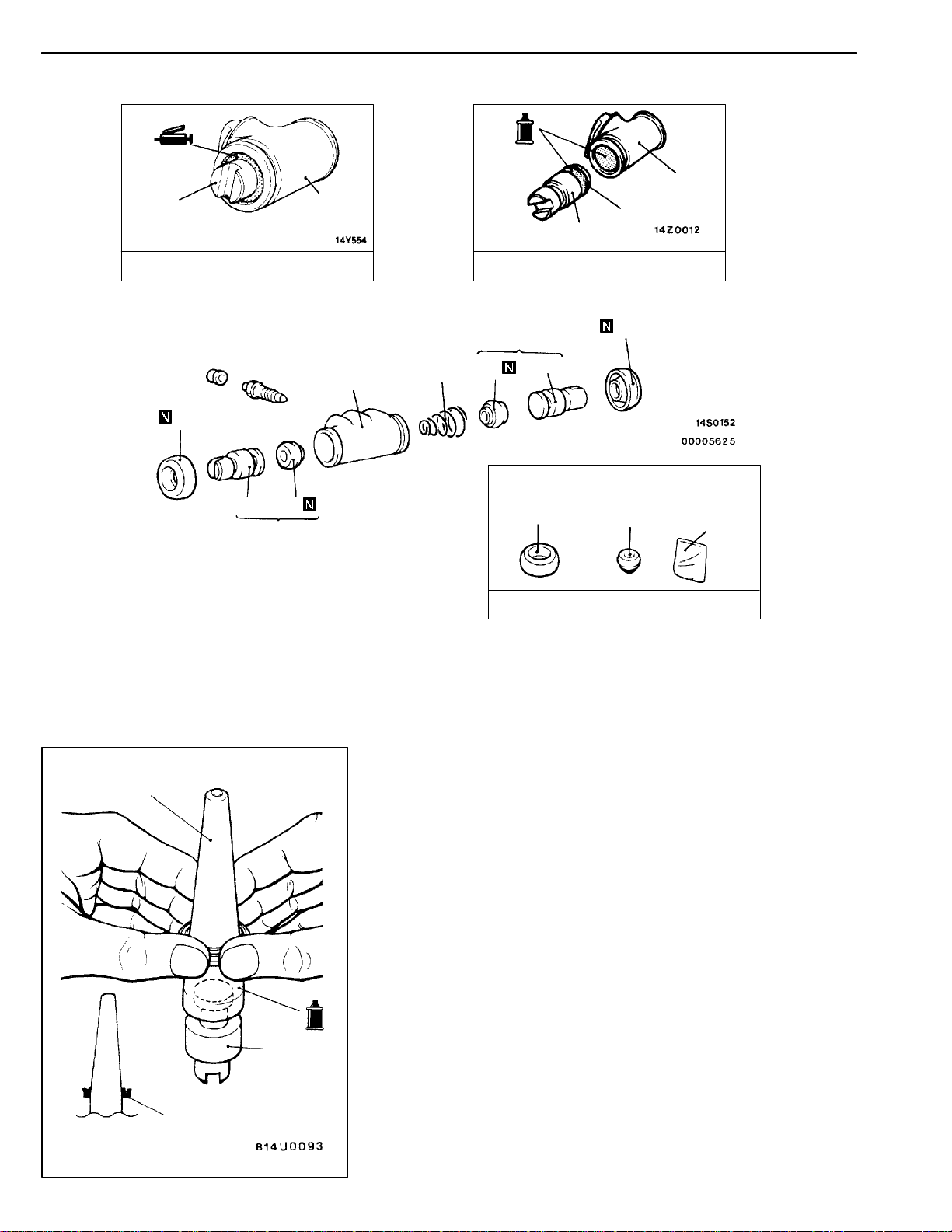
REASSEMBLY SERVICE POINT
"AA
1. Use alcohol or specified brake fluid to clean the wheel
2. Apply the specified brake fluid to the piston cups and
3. Set the piston cup on the special tool with the lip of the
PISTON CUP/PISTON REASSEMBLY
cylinder and the piston.
the special tool.
Specified brake fluid: DOT3 or DOT4
cup facing up, fit the cup onto the special tool, and then
slide it down the outside of the tool into the piston groove.
Caution
In order to keep the piston cup from becoming twisted
or slanted, slide the piston cup down the tool slowly
and carefully, without stopping.
Have the lip facing
upwards.
Page 28

35A-28
BASIC BRAKE SYSTEM -
Rear Drum Brake/Proportioning Valve
PROPORTIONING VALVE
REMOVAL AND INSTALLATION
Pre-removal Operation
Brake Fluid Draining
Flared brake line nuts
INSPECTION
35100780038
Check the piston and wheel cylinder walls for rust or damage,
and if there is any abnormality,replace the entire wheel cylinder
assembly.
35100570154
Post-installation Operation
Brake Fluid Supplying
D
Brake Line Bleeding (Refer to P.35A-10.)
D
2
1
15 Nm
1
1
Removal steps
"AA
1. Brake pipe
2. Proportioning valve
INSTALLATION SERVICE POINT
"AA
12
Connect the pipes to the hydraulic unit as shown in the
illustration.
3
4
1. Proportioning valve – Rear brake (L.H.)
2. Proportioning valve – Rear brake (R.H.)
3. Proportioning valve – Front brake (R.H.)
4. Proportioning valve – Front brake (L.H.)
5
6
5. Proportioning valve – Master cylinder (secondary)
6. Proportioning valve – Master cylinder (primary)
BRAKE PIPE CONNECTION
Page 29

35B-1
ANTI-SKID
BRAKING SYSTEM
(ABS) <2WD>
CONTENTS
GENERAL INFORMATION 3..................
SERVICE SPECIFICATIONS 5.................
LUBRICANTS 5..............................
SPECIAL TOOLS 5..........................
TROUBLESHOOTING 6.......................
ON-VEHICLE SERVICE 19...................
Brake Pedal Check and Adjustment
Refer to GROUP 35A..........................
Stop Lamp Switch Check
Refer to GROUP 35A..........................
Brake Booster Operating Test
Refer to GROUP 35A..........................
Check Valve Operation Check
Refer to GROUP 35A..........................
Proportioning Valve Function Test
Refer to GROUP 35A..........................
Brake Fluid Level Sensor Check
Refer to GROUP 35A..........................
35209000206
Bleeding Refer to GROUP 35A..................
Disc Brake Pad Check and Replacement
Refer to GROUP 35A..........................
Disc Brake Rotor Check
Refer to GROUP 35A..........................
Brake Lining Thickness Check
Refer to GROUP 35A..........................
Brake Drum Inside Diameter Check
Refer to GROUP 35A..........................
Brake Lining and Brake Drum Connection
Check Refer to GROUP 35A....................
Wheel Speed Sensor Output Voltage
Check 19......................................
ABS Warning Lamp Relay Continuity
Check 21......................................
Hydraulic Unit Check 22........................
Remedy for a Flat Battery 23...................
CONTINUED ON NEXT PAGE
Page 30

35B-2
BRAKE PEDAL Refer to GROUP 35A........
MASTER CYLINDER AND BRAKE
BOOSTER 24..............................
Master Cylinder 24.............................
DISC BRAKE Refer to GROUP 35A..........
REAR DRUM BRAKE
Refer to GROUP 35A........................
Wheel Cylinder Refer to GROUP 35A...........
PROPORTIONING VALVE 25.................
HYDRAULIC UNIT 26........................
WHEEL SPEED SENSOR 28.................
Page 31

ABS <2WD> -
General Information
35B-3
GENERAL INFORMATION
The ABS consists of components such as the wheel
speed sensors, stop lamp switch, hydraulic unit
assembly, ABS control unit (ABS-ECU) and the
ABS warning lamp. If a problem occurs in the
system, the malfunctioning components can be
Items Specifications
Master cylinder Type Tandem type (with level sensor)
I.D. mm 25.4
Brake booster Type Vacuum type, tandem
Effective dia. of power cylinder mm 180 + 205
Boosting ratio 6.5
Proportioning valve Type Dual type
Decompression ratio 0.25
Front brakes Type Floating caliper, 1-piston, ventilated disc
identified an d the trouble symptoms will be
memorized by the diagnosis function.
In addition, reading of diagnosis codes and service
data and actuator testing are possible by using
the MUT-II.
35200010222
Disc effective dia.´thickness mm 256¢24
Wheel cylinder I.D. mm 60.3
Pad thickness mm 10.0
Clearance adjustment Automatic
Rear drum brakes Type Leading trailing
Drum I.D. mm 203
Wheel cylinder I.D. mm 20.6
Lining thickness mm 4.4
Clearance adjustment Automatic
Brake fluid DOT3 or DOT4
ABS type 4-sensor, 3-channel method
Speed sensor Magnet coil type on 4 wheels
Front ABS rotor teeth 43
Rear ABS rotor teeth 43
Page 32

35B-4
CONSTRUCTION DIAGRAM
<L.H. drive vehicles>
7
6
8
1
5
4
ABS <2WD> -
2
3
General Information
<R.H. drive vehicles>
7
4
5
1. ABS relay
2. ABS warning lamp
3. Stop lamp switch
4. ABS rotor
3
2
1
6
8
5. Wheel-speed sensor
6. ABS-ECU
7. Diagnosis connector
8. Hydraulic unit
Page 33

ABS <2WD> -
Service Specifications/Lubricants/Special Tools
35B-5
SERVICE SPECIFICATIONS
Items Standard value
Wheel speed sensor internal resistance kW 1.0 - 1.5
Clearance between the wheel speed sensor mounting
surface and the ABS toothed rotor mm
Wheel speed sensor insulation resistance kW 100 or more
28.2 - 28.5
LUBRICANTS
Items Specified lubricant
Brake fluid DOT3 or DOT4
SPECIAL TOOLS
Tool Number Name Use
MB991502 MUT-II sub
assembly
For checking of ABS (Diagnosis code display
when using the MUT-II)
35200030242
35200040054
35200060210
MB991529 Diagnosis code
check harness
For checking of ABS (Diagnosis code display
when using the ABS warning lamp)
Page 34

35B-6
ABS <2WD> -
Troubleshooting
TROUBLESHOOTING
35201110129
STANDARD FLOW OF DIAGNOSTIC TROUBLESHOOTING
Refer to GROUP 00 - How to Use Troubleshooting/Inspection Service Points.
NOTES WITH REGARD TO DIAGNOSIS
The phenomena listed in the following table are not abnormal.
Phenomenon Explanation of phenomenon
System check sound When starting the engine, a thudding sound can sometimes be heard coming from inside
the engine compartment, but this is because the system operation check is being
performed, and is not an abnormality.
ABS operation sound 1. Sound of the motor inside the ABS hydraulic unit operation. (whine)
2. Sound is the generated along with vibration of the brake pedal. (scraping)
3. When ABS operates, sound is generated from the vehicle chassis due to repeated
brake application and release.
(Thump: suspension; squeak: tyres)
ABS operation
(Long braking distance)
Diagnosis detection condition can vary depending on the diagnosis code.
Make sure that checking requirements listed in the “Comment” are satisfied when checking the trouble
symptom again.
For road surfaces such as snow-covered roads and gravel roads, the braking distance for
vehicles with ABS can sometimes be longer than that for other vehicles. Accordingly, advise
the customer to drive safely on such roads by lowering the vehicle speed and not being too
overconfident.
DIAGNOSIS FUNCTION
35201120221
DIAGNOSIS CODES CHECK
Read a diagnosis code by the MUT-II or ABS warning lamp.
(Refer to GROUP 00 - How to Use Troubleshooting/Inspection
Service Points.)
ERASING DIAGNOSIS CODES
With the MUT-
II
Refer to GROUP 00 - How to Use Troubleshooting/Inspection
Service Points.
Page 35
ABS <2WD> -
Troubleshooting
35B-7
With the ABS Warning Lamp
1. Use the special tool to earth terminal (1) (diagnosis control terminal) of the diagnosis connector.
(Refer to GROUP 00 - How to Use Troubleshooting/Inspection Service Points.)
2. Stop the engine.
3. Turn on the stop lamp switch. (Depress the brake.)
4. After carrying out steps 1. to 3., turn the ignition switch to ON. Within 3 seconds after turning the
ignition switch to ON, turn off the stop lamp switch (release the brake). Then, turn the stop lamp
switch on and off a total of 10 times.
NOTE
If the ABS-ECU function has been stopped because of fail-safe operation, it will not be possible
to erase the diagnosis codes.
Ignition switch
Stop lamp switch
ABS warning lamp
ABS-ECU memory
ON
OFF
ON
OFF
ON
OFF
Within 3
seconds
Within
Within
Within
Within
Within
Within
Within
Within
Within
1
second
1
second
1
second
1
second
1
second
1
second
1
second
1
second
1
second
Within
1
second
1st 2nd 3rd 4th 5th 6th 7th 8th 9th 10th
1 second
Erasing of
ABS-ECU
diagnosis
codes
complete.
Page 36

35B-8
ABS <2WD> -
Troubleshooting
INSPECTION CHART FOR DIAGNOSIS CODES
Inspect according to the inspection chart that is appropriate for the malfunction code.
Diagnosis
code No.
11 Front right wheel speed sensor Open circuit 35B-9
12 Front left wheel speed sensor
13 Rear right wheel speed sensor
14 Rear left wheel speed sensor
15 Wheel speed sensor Abnormal output signal 35B-10
16 Power supply system 35B-10
21 Front right wheel speed sensor Short circuit 35B-9
22 Front left wheel speed sensor
23 Rear right wheel speed sensor
24 Rear left wheel speed sensor
33 Stop lamp switch system 35B-11
Inspection item Diagnosis content Reference page
35201130323
41 Front right solenoid valve 35B-26 (Replace
the hydraulic unit.)
42 Front left solenoid valve
43 Rear right solenoid valve
44 Rear left solenoid valve
51 Valve relay problem (stays on)
52 Valve relay problem (stays off)
53 Motor relay problem (stays off)
54 Motor relay problem (stays on)
55 Motor system (seized pump motor)
63 ABS-ECU
Page 37

ABS <2WD> -
Troubleshooting
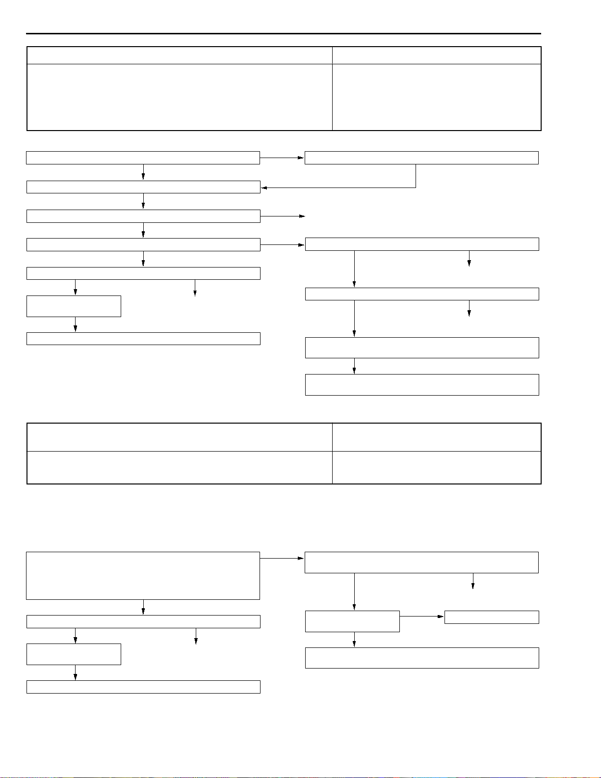
INSPECTION PROCEDURE FOR DIAGNOSIS CODES
35B-9
Code Nos.11, 12, 13 and 1 4 Wheel speed sensor
(open circuit or short circuit)
Code Nos.21, 22, 23 and 24 Wheel speed sensor
Code Nos 11, 12, 13 and 14 are output if the ABS-ECU detects an open circuit or
short-circuit in the (+) wire or ( - ) wire in any one of the four wheel speed sensors.
Code Nos.21, 22, 23 and 24 are output in the following cases.
D When there is no input from any one of the four wheel speed sensors when travelling
at several km/h or more, even though open circuit can not be verified.
D When a chipped or blocked-up ABS rotor is detected and if the anti-lock system
operates continuously because a malfunctioning sensor or a warped ABS rotor
is causing sensor output to drop.
Wheel speed sensor installation check
OK
Measure at the ABS-ECU connector A-04.
D Disconnect the connector, and measure at the harness side
connector.
D Resistances between 20 and 19, 2 and 1, 22 and 23, 6 and
5
OK:
1.0 - 1.5 kW
OK
Wheel speed sensor output voltage check (Refer to P.35B-19.)
OK
Wheel speed sensor
check (Refer to
P.35B-29.)
ABS rotor check (Refer
to P.35B-29.)
Wheel bearing check (Refer to GROUP 26 and
GROUP 27 - On-vehicle
Service.)
NG
NG
OK
NG
OK
NG
NG
Replace
Replace
Repair
Wheel speed sensor check (Refer to P.35B-29.)
Check the following connectors:
<L.H. drive vehicles>
A-09, C-115, C-75, A-39, C-74, E-14, E-13, E-11, C-123, E-12
<R.H. drive vehicles>
A-09, A-41, A-39, C-115, C-75, E-14, E-13, E-11, C-121, E-12
Check the trouble symptom.
Check the harness wire, and repair if necessary.
D Between each wheel speed sensor and ABS-ECU
Probable cause
D Malfunction of wheel speed sensor
D Malfunction of wiring harness or connector
D Malfunction of hydraulic unit
D Malfunction of wheel speed sensor
D Malfunction of wiring harness or connector
D Malfunction of ABS rotor
D Too much gap between the sensor and the rotor
D Malfunction of hydraulic unit
D Malfunction of wheel bearing
OK
OK
NG
NG
Replace
NG
Repair
Check the following connector:
OK
Check the trouble symptom.
NG
Replace the hydraulic unit.
A-04
NG
Repair
Page 38
35B-10
ABS <2WD> -
Troubleshooting
CodeNo.15 Wheel speed sensor (abnormal output signal) Probable cause
This code is output when there is an abnormality in the output signal from any one
of the four wheel speed sensors while driving (except for an open circuit or short
circuit).
D The four vehicle tires are of different sizes
D Improper installation of wheel speed sensor
D Malfunction of wheel speed sensor
D Malfunction of wiring harness or connector
D Malfunction of ABS rotor
D Malfunction of wheel bearing
D Malfunction of hydraulic unit
Are the sizes of all four tires identical?
YES
Check the trouble symptom.
NG
Wheel speed sensor installation check
OK
Wheel speed sensor output voltage check (Refer to P.35B-19.)
OK
Check the following connector:
OK
Check the trouble symptom.
NG
Replace the hydraulic unit.
A-04
NG
Repair
NO
NG
NG
Equip the vehicle with tires of identical sizes.
Repair
Wheel speed sensor check (Refer to P.35B-29.)
ABS rotor check (Refer to P.35B-29.)
Wheel bearing check (Refer to GROUP 26 and GROUP 27 On-vehicle Service.)
Check the harness wire, and repair if necessary.
D Between each wheel speed sensor and ABS-ECU
Code No.16 ABS-ECU power supply system (abnormal
voltage drop or rise)
This code is output if the ABS-ECU power supply voltage drops below or rises above
the rated values.
Furthermore, if the voltage returns to normal, this code is no longer output.
OK
OK
NG
NG
Replace
NG
Replace
Probable cause
D Malfunction of battery
D Malfunction of wiring harness or connector
D Malfunction of hydraulic unit
Caution
If battery voltage drops or rises during inspection, this code will be output as well. If the voltage
returns to standard value, this code is no longer output.
Before carrying out the following inspection, check the battery level, and refill it if necessary.
Measure at the ABS-ECU connector A-04.
D Disconnect the connector, and measure at the harness side
connector.
D Start the engine. Voltage between 4 and body earth
OK:
Battery voltage
OK
Check the following connector:
OK
Check the trouble symptom.
NG
Replace the hydraulic unit.
A-04
NG
Repair
NG
Check the following connectors:
A-04, C-75, C-66 <L.H. drive vehicles>, C-134, C-131
OK
Check the trouble symptom.
NG
Check the harness wire, and repair if necessary.
D Between ignition switch and ABS-ECU
OK
NG
Repair
Check the battery.
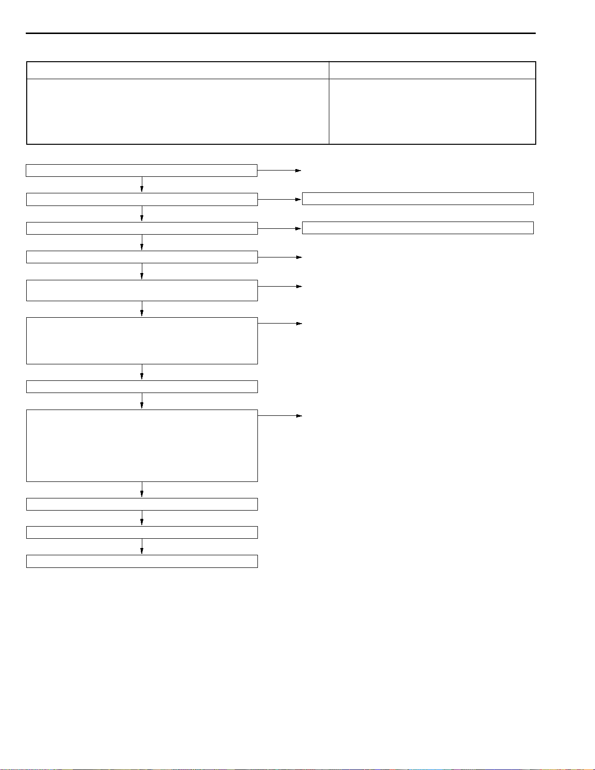
Page 39

ABS <2WD> -
Troubleshooting
35B-11
CodeNo.33 Stop lamp switch system (opencircuit orstop
lamp stays ON)
This code is output in the following cases.
D If the stop lamp switch is continuously on for 15 minutes or more even though
the ABS system is not operating.
D If there is an open circuit in the stop lamp switch input circuit harness.
NG
NO
Stop lamp switch installation check
Stop lamp switch check (Refer to GROUP 35A - Brake Pedal.)
Check the following connectors:
C-12 <R.H. drive vehicles>, C-142, C-134, C-02, C-65, C-75, A-04
Check the trouble symptom.
Check the harness wire, and repair if necessary.
D Between fusible link No.1 and ABS-ECU
Does the stop lamp turn on and off normally?
YES
Measure at the ABS-ECU connector A-04.
D Disconnect the connector, and measure at the harness side
connector.
D Stop lamp switch: ON
D Voltage between 18 and body earth
OK:
Battery voltage
OK
Check the following
connector:
Check the trouble symptom.
Replace the hydraulic
unit.
OK
A-04
NG
Repair
NG
Check the following
connectors:
A-04, C-75, C-65
Check the trouble symptom.
Check the harness wire,
and repair if necessary.
D Between stop lamp
switch and ABS-ECU
NG
OK
Repair
NG
Probable cause
D Malfunction of stop lamp switch
D Malfunction of wiring harness or connector
D Malfunction of hydraulic unit
OK
OK
OK
NG
NG
Repair
NG
Replace
NG
Repair
ABS
warning
lamp
Ignition
switch
ABS warning lamp
Illuminated
Not
illuminated
START
ON
ACC,
LOCK
Approx. 3 s
Approx. 3 s
ABS WARNING LAMP INSPECTION
35201200123
Check that the ABS warning lamp illuminates as
follows.
1. When the ignition key is turned to “ON”, th e ABS warning
lamp illuminates for approximately 3 seconds and then
switches off.
2. When the ignition key is turned to “START”, the ABS
warning lamp remains illuminated.
3. When the ignition key is turned from “START” back to
“ON”, the ABS warning lamp illuminates for approximately
3 seconds and then switches off.
NOTE
The ABS warning lamp may remain on until the vehicle
reaches a speed of several km/h. This is limited to cases
where diagnosis code Nos.21 - 24 and 55 have been
recorded because of a previous problem occurring. In
this case, the ABS-ECU keeps the warning lamp
illuminated until the problem corresponding to that
diagnosis code can be detected.
4. If the illumination is other than the above, check the
diagnosis codes.
Page 40

35B-12
ABS <2WD> -
Troubleshooting
INSPECTION CHART FOR TROUBLE SYMPTOMS
35201140289
Get an understanding of the trouble symptoms and check according to the inspection procedure chart.
Trouble symptoms Inspection procedure
No.
Communication between the MUT-IIand the whole system is not
1 35B-12
possible.
Communication between the MUT-IIand the ABS-ECU is not possible. 2 35B-13
When the ignition key is turned to “ON” (engine stopped), the ABS
3 35B-14
warning lamp does not illuminate.
Even after the engine is started, the ABS warning lamp remains
4 35B-15
illuminated.
Faulty ABS operation 5 35B-16
Reference page
Caution
1. If steering movements are made when driving at high speed, or when driving on road surfaces
with low frictional resistance, or when passing over bumps, the ABS may operate even though
suddenbraking is notbeing applied.Because ofthis, whengetting informationfrom thecustomer,
check if the problem occurred while driving under such conditions as these.
2. During ABS operation, the brake pedal may vibrate or may not be able to be depressed. Such
phenomena are due to intermittent changes in hydraulic pressure inside the brake line to prevent
the wheels from locking and is not an abnormality.
INSPECTION PROCEDURE FOR TROUBLE SYMPTOMS
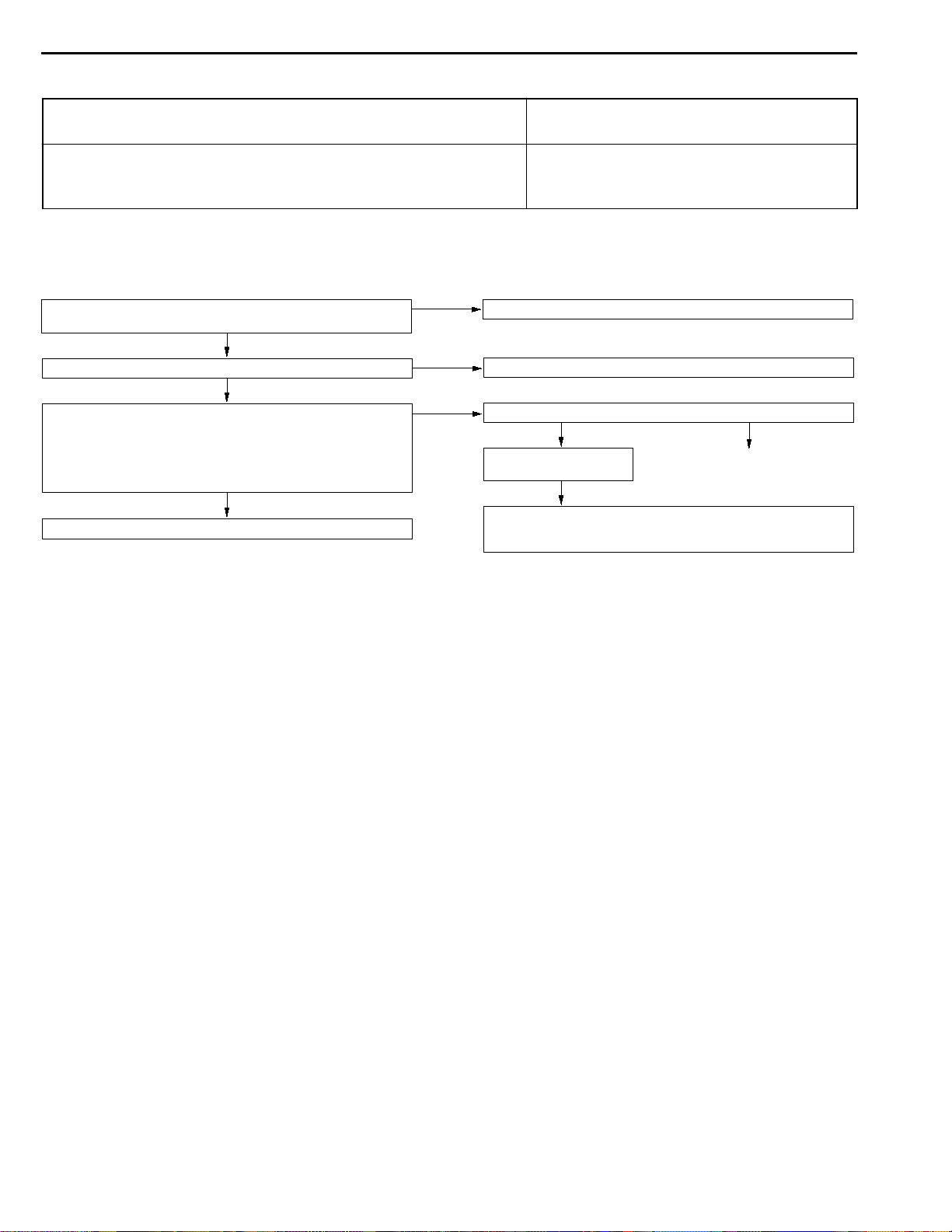
Inspection Procedure 1
Communicationbetween the MUT-IIandthewhole system
is not possible.
The cause may be a malfunction of the power supply circuit or the earth circuit of
the diagnosis connector.
Measure at the diagnosis connector C-20.
Voltage between 16 and body earth
D
Measure at the diagnosis connector C-20.
D
Check the trouble symptom.
Replace the MUT-II.
Battery voltage
OK:
OK
Continuity between 4 and body earth, and between 5 and body
earth
Continuity
OK:
OK
NG
NG
NG
Probable cause
Malfunction of diagnosis connector
D
Malfunction of wiring harness or connector
D
Check the following connectors:
<L.H. drive vehicles>
C-20, C-66, C-63, C-132, C-141
<R.H. drive vehicles>
C-20, C-66, C-62, C-14
OK
Check the trouble symptom.
NG
Check the harness wire, and repair if necessary.
Between power supply and diagnosis connector
D
Check the following connector:
OK
Check the trouble symptom.
NG
Check the harness wire, and repair if necessary.
Between diagnosis connector and earth
D
NG
Repair
C-20
NG
Repair
Page 41

Inspection Procedure 2
ABS <2WD> -
Troubleshooting
35B-13
Communication between MUT-IIand the ABS-ECU is not
possible.
The cause may be an open circuit in the ABS-ECU power supply circuit or an open
circuit in the diagnosis output circuit.
Measure at the diagnosis connector C-20 and the ABS-ECU connector A-04.
D Disconnect the connector, and measure at the harness side
connector.
D Continuity between the following terminals
ABS-ECU side - Diagnosis connector side
OK:
Measure at the ABS-ECU connector A-04.
D Disconnect the connector, and measure at the harness side
connector.
D Ignition switch: ON
D Voltage between 4 and body earth
OK:
14 - 1
7-7
Continuity
OK
Battery voltage
OK
NG
NG
Check the following connectors:
<PETROL-POWERED VEHICLES>
C-51, C-49, C-83, C-66, C-20
<DIESEL-POWERED VEHICLES>
C-51, C-56, C-83, C-66, C-20
Check the trouble symptom.
Check the harness wire, and repair if necessary.
D Between ABS-ECU and diagnosis connector
Check the following connectors:
A-04, C-75, C-66 <L.H. drive vehicles>, C-134, C-131
Check the trouble symptom.
Check the harness wire, and repair if necessary.
D Between ignition switch and ABS-ECU
Probable cause
D Blown fuse
D Malfunction of wiring harness or connector
D Malfunction of hydraulic unit
OK
NG
OK
NG
NG
Repair
NG
Repair
Measure at the ABS-ECU connector A-04.
D Disconnect the connector, and measure at the harness side
connector.
D Continuity between 8 and body earth, between 11 and body
earth and between 24 and body earth
OK:
Continuity
OK
Check the following connector:
OK
Check the trouble symptom.
NG
Replace the hydraulic unit.
A-04
NG
Repair
NG
Check the following connector:
OK
Check the trouble symptom.
NG
Check the harness wire, and repair if necessary.
D Between ABS-ECU and earth
A-04
NG
Repair
Page 42

35B-14
Inspection Procedure 3
ABS <2WD> -
Troubleshooting
When the ignition key is turned to “ON” (engine stopped),
the ABS warning lamp does not illuminate.
The cause may be an open circuit in the lamp power supply circuit, a blown lamp,
a malfunction of the ABS warning lamp relay or an open circuit between the ABS
warning lamp and the earth.
Fuse check
Multi-purpose fuse No.13
OK
Measure at the connector C-50.
D Disconnect the connector, and measure at the combination
meter side connector.
D Ignition switch: ON
D ABS warning lamp condition when terminal 2 <LHD> or terminal
7 <RHD> is earthed.
OK:
Illuminates
OK
ABS warning lamp relay check (Refer to P.35B-21.)
OK
Replace the ABS warning
lamp relay.
NG
NG
Refer to GROUP 00 - Inspection Service Points for Blown Fuse.
NG
Check whether the ABS warning lamp bulb is burnt out.
Check the following
connectors:
D-01, D-03, C-135, C-131
Check the trouble symptom.
Replace the combination meter.
Probable cause
D Blown fuse
D Burn out ABS warning lamp bulb
D Malfunction of ABS warning lamp relay
D Malfunction of wiring harness or connector
D Malfunction of hydraulic unit
OK
Replace the ABS warning
lamp bulb.
NG
OK
NG
Repair
NG
Disconnect the ABS warning lamp relay connector A-05X and ABSECU connector A-04, and measure at the harness side connector
of ABS warning lamp relay.
D Ignition switch: ON
D Voltage between 5 and body earth
OK:
Battery voltage
OK
Replace the hydraulic unit.
NG
Check the following connector:
OK
Check the trouble symptom.
NG
Check the harness wire, and repair if necessary.
D Between ABS warning lamp and ABS warning lamp relay
D Between ABS warning lamp relay and earth
A-05X
NG
Repair
Page 43
Inspection Procedure 4
ABS <2WD> -
Troubleshooting
35B-15
Even after the engine is started, the ABS warning lamp
Probable cause
remains illuminated.
The cause is probably a short-circuit in the ABS warning lamp illumination circuit. D Malfunction of combination meter
D Malfunction of ABS warning lamp relay
D Malfunction of wiring harness (short circuit)
D Malfunction of hydraulic unit
NOTE
This trouble symptom is limited to cases where communication with the MUT-IIis possible (ABS-ECU
power supply is normal) and the diagnosis code is a normal diagnosis code.
Does the ABS warning lamp stay illuminated when the connector
C-50 is disconnected and the ignition switch is turned to ON?
NO
ABS warning lamp relay check (Refer to P.35B-21.)
OK
Disconnect the ABS warning lamp relay connector A-05X and ABSECU connector A-04, and measure at the harness side connector
of ABS warning lamp relay.
D Ignition switch: ON
D Voltage between 2 and body earth
OK:
Battery voltage
OK
Replace the hydraulic unit.
YES
NG
NG
Replace the combination meter.
Replace the ABS warning lamp relay.
Check the following connectors:
OK
Check the trouble symptom.
NG
Check the harness wire, and repair if necessary.
D Between ABS warning lamp and ABS warning lamp relay
D Between ABS warning lamp relay and ABS-ECU
A-05X, A-04
NG
Repair
Page 44
35B-16
Inspection Procedure 5
ABS <2WD> -
Troubleshooting
Faulty ABS operation
This varies depending on the driving conditions and the road surface conditions, so
problem diagnosis is difficult. However, if a normal diagnosis code is displayed, carry
out the following inspection.
Wheel speed sensor installation check
OK
Wheel speed sensor output voltage check (Refer to P.35B-19.)
NG
Wheel speed sensor check (Refer to P.35B-29.)
OK
ABS rotor check (Refer to P.35B-29.)
OK
Wheel bearing check (Refer to GROUP 26 and GROUP 27 On-vehicle Service.)
OK
Check the following connectors:
<L.H. drive vehicles>
A-09, C-115, C-75, A-39, C-74, E-14, E-13, E-11, C-123, E-12
<R.H. drive vehicles>
A-09, A-41, A-39, C-115, C-75, E-14, E-13, E-11, C-121, E-12
OK
NG
OK
NG
NG
NG
NG
Repair
Hydraulic unit check (Refer to P.35B-22.)
Replace the wheel speed sensor.
Repair
Repair
Repair
Probable cause
D Improper installation of wheel speed sensor
D Malfunction of wiring harness or connector
D Malfunction of wheel speed sensor
D Malfunction of ABS rotor
D Foreign material adhering to wheel speed sensor
D Malfunction of wheel bearing
D Malfunction of hydraulic unit
Check the trouble symptom.
NG
Measure at the ABS-ECU connector A-04.
D Disconnect the connector, and measure at the harness side
connector.
D Resistances between 20 and 19, 2 and 1, 22 and 23, 6 and
5
OK:
1.0 - 1.5 kW
(The sensor harness and connector should be moved while
these inspections are carried out.)
OK
Check the following connector:
Check the trouble symptom.
Replace the hydraulic unit.
A-04
OK
NG
NG
Repair
Page 45

ABS <2WD> -
Troubleshooting
35B-17
DATA LIST REFERENCE TABLE
35201150206
The following items can be read by the MUT-II from the ABS-ECU input data.
1. When the system is normal
Item No. Check item Checking requirements Normal value
11 Front-right wheel speed sensor Perform a test run Vehicle speeds
displayed on the
12 Front-left wheel speed sensor
speedometer
and MUT-IIare
13 Rear-right wheel speed sensor
identical.
14 Rear-left wheel speed sensor
16 ABS-ECU power supply
voltage
Ignition switch power supply voltage and valve
monitor voltage
9.2 - 17.5 V
33 Stop lamp switch Depress the brake pedal. ON
Release the brake pedal. OFF
2. When the ABS-ECU shut off ABS operation.
When the diagnosis system stops the ABS-ECU, the MUT-II display data will be unreliable.
ACTUATOR TEST REFERENCE TABLE
35201160025
The MUT-II activates the following actuators for testing.
NOTE
1. If the ABS-ECU runs down, actuator testing cannot be carried out.
2. Actuator testing is only possible when the vehicle is stationary. If the vehicle speed during actuator
testing exceeds 10 km/h, forced actuation will be canceled.
3. During t he actuator test, the ABS warning lamp will illuminate and the anti-skid control will b e cancelled.
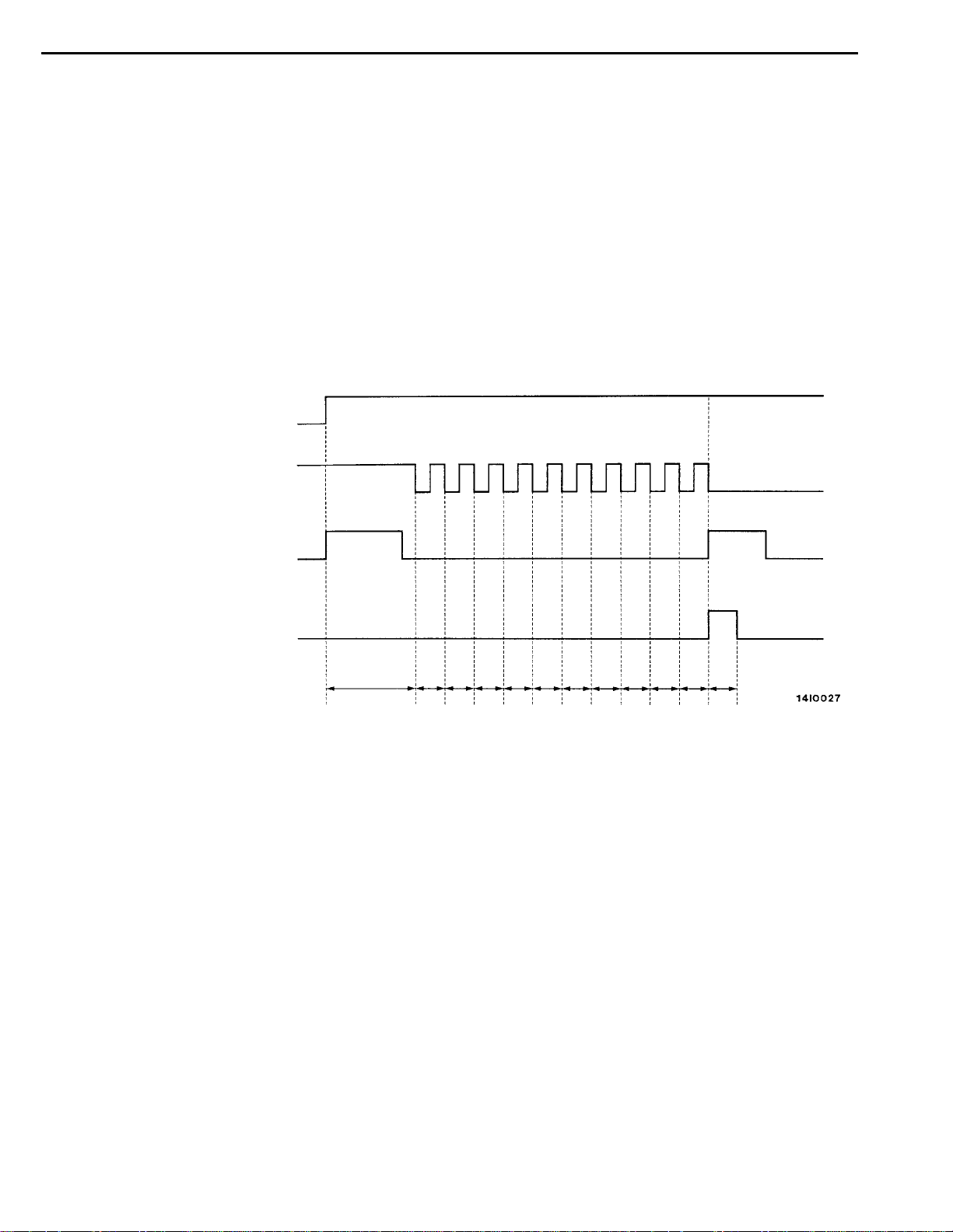
ACTUATOR TEST SPECIFICATIONS
Activation pattern
Solenoid
valve
Pump
motor
A
B
C
48 ms
ON
OFF
Start of
forced
action
1s
End of forced
action
2s
8ms
No. Item
01 Solenoid valve for front-left
wheel
02 Solenoid valve for front-right
wheel
03 Solenoid valve for rear-left
wheel
04 Solenoid valve for rear-right
wheel
Solenoid valves and pump
motors in the hydraulic unit
(simple inspection mode)
NOTE
A: Hydraulic pressure increase
B: Hydraulic pressure holds
C: Hydraulic pressure decrease
Page 46

35B-18
ABS <2WD> -
Troubleshooting
CHECK AT ABS-ECU
TERMINAL VOLTAGE CHECK CHART
1. Measure the voltage between each terminal and earth.
2. The terminal layout is shown in the illustration below.
Terminal No. Check item Checking requirements Normal condition
4 ABS-ECU power sup- Ignition switch: ON Battery voltage
ply
Ignition switch: START 0V
supply
input
II
When the MUT-IIis connected Serial communication
with MUT-
When the MUT-IIis not connected 1 V or less
Always Battery voltage
When the MUT-IIis not connected Approx. 12 V
II
7 MUT-
9 Solenoid valve power
14 Diagnosis changeover When the MUT-IIis connected 0V
35201180229
16 ABS valve transistor
output
18 Stop lamp switch input Ignition switch: ON Stop lamp switch: ON Battery voltage
25 Motor power supply Always Battery voltage
Ignition switch: ON When the lamp is
switched off
When the lamp is
illuminated
Stop lamp switch: OFF 1 V or less
2 V or less
Battery voltage
RESISTANCE AND CONTINUITY BETWEEN HARNESS-SIDE CONNECTOR TERMINALS
1. Turn the ignition switch off and disconnect the ABS-ECU connectors before checking resistance and
continuity.
2. Check them between the terminals indicated in the table below.
3. The terminal layouts are shown in the illustrations below.
Terminal No. Signal Normal condition
1-2 Wheel speed sensor (front left) 1.0 - 1.5 k
5-6 Wheel speed sensor (rear left) 1.0 - 1.5 k
19 - 20 Wheel speed sensor (front right) 1.0 - 1.5 k
W
W
W
Page 47

ABS <2WD> -
Terminal No. Normal conditionSignal
23 - 22 Wheel speed sensor (rear right) 1.0 - 1.5 kW
8 - Body earth Solenoid valve earth Continuity
24 - Body earth Motor earth
Troubleshooting/On-vehicle Service
35B-19
ABS-ECU connector
(harness side)
ON-VEHICLE SERVICE
35200160224
WHEEL SPEED SENSOR OUTPUT VOLTAGE
CHECK
1. Lift up the vehicle and release the parking brake.
2. Disconnect the ABS-ECU connector, and then use the
special tool (inspection harness for connector pin contact
pressure) to measure the output voltage at the
harness-side connector.
3. Rotate the wheel to be measured at approximately 1/2 - 1
rotation per second, and check the output voltage using
a circuit tester or an oscilloscope.
Wheel
speed
sensor
Terminal 1 19 5 23
No.
Output voltage
When measuring with a circuit tester:
When measuring with an oscilloscope:
4. If the output voltage is lower than the above values, the
reason could be as follow:
Faulty wheel speed sensor.
D
So replace the wheel speed sensor.
Front left Front
right
2 20 6 22
Rear left Rear
42 mV or more
120 mV p-p or more
right
Page 48

35B-20
When turning by hand
When idling (5- 6 km/h),
1st gear (manual transmission) or D range (automatic transmission)
10.0 ms/DIV 1 V/DIV
ABS <2WD> -
Inspecting Waveforms With An Oscilloscope
Use the following method to observe the output voltage
waveform from each wheel sensor with an oscilloscope.
D Start the engine, and rotate the front wheels by engaging
NOTE
1. Check the connection of the sensor harness and
2. The waveform measurements can also be taken while
3. The output voltage will be small when the wheel speed
On-vehicle Service
1st gear (vehicles with manual transmission) or D range
(vehicles with automatic transmission). Turn the rear
wheels manually so that they rotate at a constant speed.
connector before using the oscilloscope.
the vehicle is actually moving.
is low, and similarly it will be large when the wheel speed
is high.
Points In Waveform Measurement
Symptom Probable causes Remedy
Too small or zero waveform
amplitude
Waveform amplitude fluctuates
excessively (this is no problem if
the minimum amplitude is 100 mV
or more)
Noisy or disturbed waveform Open circuit in sensor Replace sensor
Faulty wheel speed sensor Replace sensor
Axle hub eccentric or with large runout Replace hub
Open circuit in harness Correct harness
Incorrectly mounted wheel speed sensor Mount correctly
Rotor with missing or damaged teeth Replace rotor
Caution
Because the wheel speed sensor cables move together with the front and rear suspension, they
vibrate greatly when driving over poor road surfaces. As a result, the sensor harnesses should
also be shaken when monitoring of output waveforms of the wheel speed sensors in order to
simulate conditions such as driving over poor road surfaces.
Page 49

ABS <2WD> -
On-vehicle Service
35B-21
<L.H. drive vehicles>
<R.H. drive vehicles>
ABS WARNING LAMP RELAY CONTINUITY
CHECK
Battery voltage Terminal No.
1 2 3 5
Power is not supplied
Power is supplied
35200930023
Page 50

35B-22
ABS <2WD> -
On-vehicle Service
HYDRAULIC UNIT CHECK
35200170227
Caution
Turn the ignition switch off before connecting or disconnecting the MUT-II.
1. Jack up the vehicle an d support the vehicle with rigid racks placed at t h e specified jack-up points
or place the wheels which are checked on the rollers of the braking force tester.
Caution
1. The roller of the braking force tester and the tyre should be dry during testing.
2. When testing the front brakes, apply the parking brake, and when testing the rear brakes,
stop the front wheels by chocking them.
2. Release the parking brake, and feel the drag force (drag torque) on each road wheel.
When using the braking force tester, take a reading of the brake drag force.
3. Turn the ignition key to the OFF position and set the MUT-II.
4. After checking that the shift lever <M/T> or the selector lever <A/T> is in neutral, start the engine.
5. Use the MUT-II to force-drive the actuator.
NOTE
1. During the actuator test, the ABS warning lamp will illuminate a nd the anti-skid control will be
cancelled.
2. When the ABS has been interrupted by the fail-safe function, the MUT-II actuator testing cannot
be used.
6. Turn the wheel by hand and check the change in braking force when the brake pedal is depressed.
When using the braking force tester, depress the brake pedal until the braking force is at the following
values, and check that the braking force decreases when the actuator is force-driven.
Front wheel 785 - 981 N
Rear wheel 588 - 784 N
The result should be as shown in the following diagram.
Depressed
Pedal operation
MUT-IIactuator test
(Item No. 01, 02, 03, 04) start
2 seconds
3 seconds
Solenoid valve
position
Checking the
brake force
Released
Increase in pressure
Steady pressure
Reduction in pressure (when not working)
Lock
Drag force when the pedal is free
1 seconds
7. If the result of inspection is abnormal, correct according to the “Diagnosis Table” (Refer to P.35B-23).
8. After inspection, disconnect the MUT-II immediately after turning the ignition switch to OFF.
Page 51

Diagnosis Table
ABS <2WD> -
On-vehicle Service
35B-23
No. Operation Judgement
- Normal
01 (1) Depress brake pedal
to lock wheel.
(2) Using the MUT-II,
select the wheel to be
02
03
04 Hydraulic unit
checked and force the
actuator to operate.
(3) Turn the selected
wheel manually to
check the change of
brake force.
Brake force
released for 3
seconds after
locking. pressed.
Judgement
- Abnormal
Wheel does not
lock when brake
pedal is de-
Brake force is
not released
Probable cause Remedy
Clogged brake
line other than
hydraulic unit
Clogged hydraulic circuit in
hydraulic unit
Incorrect hydraulic unit brake
tube connection
solenoid valve
not functioning
correctly
REMEDY FOR A FLAT BATTERY
When booster cables are used to start the engine when the
battery is completely flat and then the vehicle is immediately
Fusible link
driven without waiting for the battery to recharge itself to
some extent, the engine may misfire, and driving might not
be possible.
This happens because ABS consumes a great amount of
current for its self-check function; the remedy is to either
allow the battery to recharge sufficiently, or to remove the
fusible link for ABS circuit, thus disabling the anti-skid brake
system. The ABS warning lamp will illuminate when the fusible
link (for ABS) is removed.
After the battery has sufficiently recharged, install the fusible
link (for ABS) and restart the engine; then check to be sure
the ABS warning lamp is not illuminated.
Check and clean
brake line
Replace hydraulic unit assembly
Connect correctly
Replace hydraulic unit assembly
35200350188
Page 52
35B-24
ABS <2WD> -
Master Cylinder and Brake Booster
MASTER CYLINDER AND BRAKE BOOSTER
REMOVAL AND INSTALLATION
Refer to GROUP 35A.
MASTER CYLINDER
DISASSEMBLY AND REASSEMBLY
9
2
1
10
3
4
5
Master cylinder kit
35200400142
35200450147
11
12
13
7
10
8
6
9
13
14
Disassembly steps
1. Reservoir cap assembly
2. Reservoir cap
3. Diaphragm
4. Filter
5. Brake fluid level indicator assembly
6. Float
7. Spring pin
14
11
12
13 12
Brake fluid: DOT3 or DOT4
8. Reservoir tank
9. Reservoir seal
10. Pin
11. Piston retainer
12. Primary piston assembly
13. Secondary piston assembly
14. Master cylinder body
INSPECTION
Check the inner surface of master cylinder body for rust
D
or pitting.
Check the primary and secondary pistons for rust, scoring,
D
wear, damage or wear.
Check the diaphragm for cracks and wear.
D
35200460027
Page 53

ABS <2WD> -
Proportioning Valve
35B-25
PROPORTIONING VALVE
REMOVAL AND INSTALLATION
Pre-removal Operation
Brake Fluid Draining
Flared brake line nuts
15 Nm
1
35200570126
Post-installation Operation
D Brake Fluid Supplying
D Brake Line Bleeding (Refer to GROUP 35A -
On-vehicle Service.)
2
1
Removal steps
"AA
1. Brake pipe
2. Proportioning valve
INSTALLATION SERVICE POINT
"AA
1
2
Connect the pipes to the hydraulic unit as shown in the
illustration.
1. Proportioning valve – Rear brake (L.H.)
34
2. Proportioning valve – Rear brake (R.H.)
3. Proportioning valve – Hydraulic unit
4. Proportioning valve – Hydraulic unit
BRAKE PIPE CONNECTION
Page 54

35B-26
ABS <2WD> -
Hydraulic Unit
HYDRAULIC UNIT
REMOVAL AND INSTALLATION
Pre-removal Operation
Brake Fluid Draining
<L.H. drive vehicles>
1
35200860261
Post-installation Operation
D Brake Fluid Supplying
D Brake Line Bleeding
(Refer to GROUP 35A - On-vehicle Service.)
D Brake Pedal Adjustment
(Refer to GROUP 35A - On-vehicle Service.)
<R.H. drive vehicles>
2
15 Nm
2
2
3
4
9Nm
22 Nm
1
3
9Nm
4
22 Nm
AA"
AB"
"AA
Removal steps
1. Harness connector
2. Brake pipe connection
3. Hydraulic unit and ABS-ECU
4. Hydraulic unit bracket assembly
Page 55

Locking lever
ABS <2WD> -
REMOVAL SERVICE POINT
AA"
Raise the locking lever as shown in the illustration, and then
disconnect the harness connector.
Hydraulic Unit
HARNESS CONNECTOR REMOVAL
35B-27
AB"
Caution
1. The hydraulic unit assembly is heavy, and so care
2. The hydraulic unit assembly is not to be disassem-
3. The hydraulic unit assembly must not be dropped
4. The hydraulic unit assembly must not be turned
1
6
3
2
5
4
INSTALLATION SERVICE POINT
"AA
Connect the pipes to the hydraulic unit assembly as shown
in the illustration.
1. To the proportioning valve (RH)
2. To the proportioning valve (LH)
3. From the master cylinder (Primary)
4. From the master cylinder (Secondary)
5. To the front brake (RH)
6. To the front brake (LH)
HYDRAULIC UNIT ASSEMBLY REMOVAL
should be taken when removing it.
bled; its nuts and bolts should absolutely not be loos-
ened.
or otherwise subjected to impact shocks.
upside down or laid on its side.
BRAKE PIPE CONNECTION
Page 56

35B-28
ABS <2WD> -
Wheel Speed Sensor
WHEEL SPEED SENSOR
REMOVAL AND INSTALLATION
Post-installation Operation
Wheel Speed Sensor Output Voltage Check
(Refer to P.35B-19.)
<Front> <Rear>
1
35200830279
3
2
AA""AA
AA""AA
Front speed sensor removal steps
D
Splash Shield Removal (Refer to
GROUP 42 - Fender.)
1. Front speed sensor
2. Front ABS rotor (Refer to GROUP
26 - Drive Shaft.)
Rear speed sensor removal steps
3. Rear speed sensor
4. Rear ABS rotor (Refer to GROUP
27 - Rear Axle Hub.)
REMOVAL SERVICE POINT
AA"
Caution
Be careful when handling the pole piece at the tip of
the speed sensor and the toothed edge of the rotor so
as not to damage them by striking against other parts.
4
NOTE
The front rotor is integrated with the drive shaft and is not
disassembled.
FRONT SPEED SENSOR/REAR SPEED SENSOR
REMOVAL
Page 57

ABS <2WD> -
Wheel Speed Sensor
35B-29
Front Rear
ABS
rotor’s
toothed
surface
Front Rear
ABS
rotor’s
toothed
surface
INSTALLATION SERVICE POINT
"AA
The clearance between the wheel speed sensor and the ABS
rotor’s toothed surface is not adjustable, but measure the
distance between the sensor installation surface and the ABS
rotor’s toothed surface.
Standard value: 28.2 - 28.5 mm
INSPECTION
SPEED SENSOR
1. Check whether any metallic foreign material has adhered
2. Measure the resistance between the speed sensor
3. Check the speed sensor cable for breakage, damage
FRONT SPEED SENSOR/REAR SPEED SENSOR
INSTALLATION
35200840227
to the pole piece at the speed sensor tip, and if so, remove
it.
Also check whether the pole piece is damaged, and if
so, replace it with a new one.
NOTE
The pole piece can become magnetized because of the
magnet but into the speed sensor, with the result that
metallic foreign material easily adheres to it. Moreover,
the pole piece may not be able to function to correctly
sense the wheel rotation speed if it is damaged.
terminals.
Standard value: 1.0 - 1.5 k
W
If the internal resistance of the speed sensor is not within
the standard value, replace with a new speed sensor.
or disconnection; replace with a new one if a problem
is found.
NOTE
When checking for cable damage, remove the cable clamp
part from the body and then bend and pull the cable
near the clamp to check whether or not temporary
disconnection occurs.
Page 58
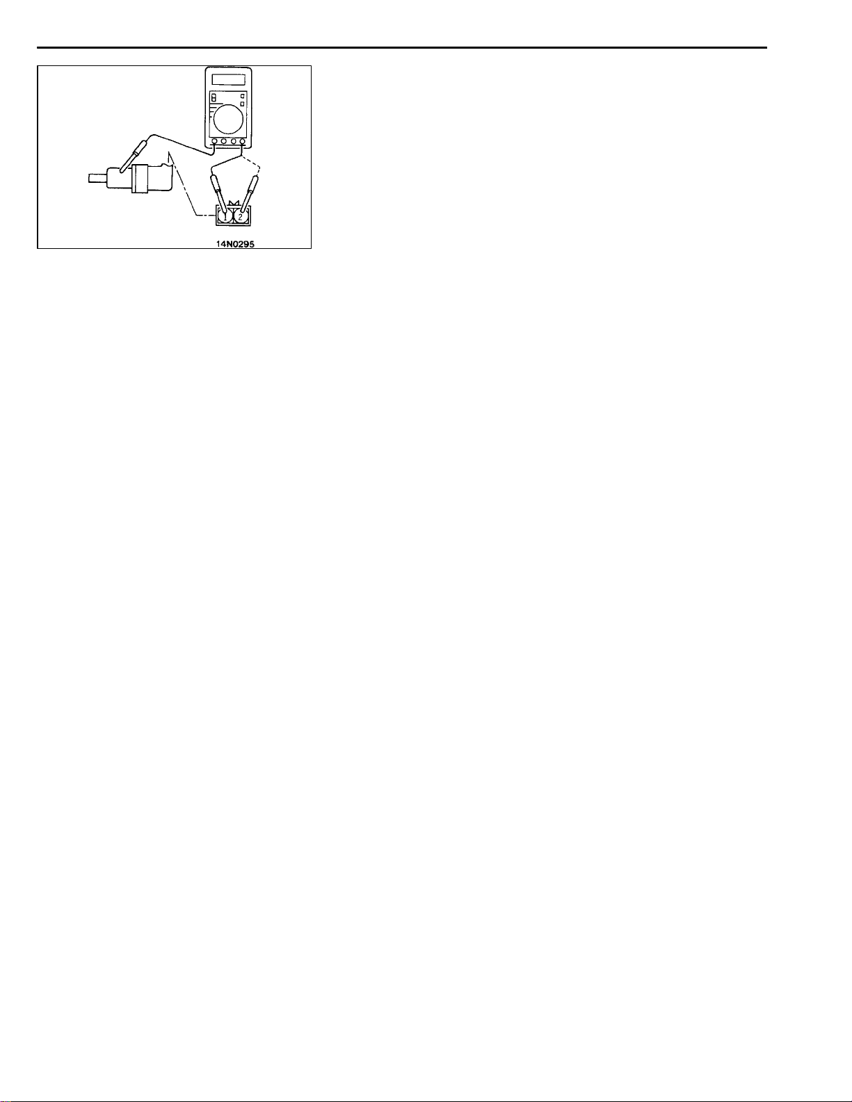
35B-30
ABS <2WD> -
SPEED SENSOR INSULATION INSPECTION
1. Remove all connections from the speed sensor, and then
2. If the speed sensor insulation resistance is outside the
ABS TOOTHED ROTOR
Check whether ABS rotor teeth are broken or deformed, and,
if so, replace the ABS rotor.
Wheel Speed Sensor
measure the resistance between terminals 1 and 2 and
the body of the speed sensor.
Standard value: 100 kWor more
standard value range, replace with a new speed sensor.
 Loading...