

Page 1

TASKE ToolBox
Installation Guide
Version 7.0
Microsoft© Windows Version for the
MITEL® SX-2000™ PBX
© 1999 TASKE Technology Inc.
Printed in Canada.
TASKE is a registered trademark of TASKE Technology Inc.
Windows 95, Windows 98, Windows NT and Microsoft are trademarks of Microsoft Corporation.
MITEL and SX-2000 are trademarks, and ACD 2000 Telemarketer is a registered trademark of Mitel Corporation.
Page 2

The TASKE Software License
1. GRANT OF LICENSE
TASKE Technology grants to you, the end user, the right to use one copy of the TASKE ToolBox
programs (the “SOFTWARE”) on a single terminal that is connected to a single computer (with
a single CPU). You may not copy the SOFTWARE or otherwise use it on more than one
computer or computer terminal at the same time UNLESS you have purchased a TASKE
Network ToolBox, in which case you are limited to the number of simultaneous users as called
for in your network license.
2. COPYRIGHT
The SOFTWARE is owned by TASKE and is protected by U.S. and Canadian copyright laws and
international treaty provisions. Therefore, you must treat the SOFTWARE like any other
copyrighted material (such as a book or musical recording) EXCEPT that you may either a) make
a copy of the SOFTWARE solely for backup or archival purposes or b) transfer the SOFTWARE
to a single hard disk provided that you keep the original solely for backup or archival purposes.
3. OTHER RESTRICTIONS
You may not RENT or LEASE the SOFTWARE, but you may transfer the SOFTWARE with the
accompanying written materials on a permanent basis provided that you retain no copies and the
recipient agrees to the terms of this Agreement. You may not reverse engineer, decompile or
disassemble the SOFTWARE.
4. LIMITED WARRANTY
TASKE warrants that a) the SOFTWARE will perform substantially in accordance with the
accompanying printed materials for a period of 365 days from the date of receipt, and b) any
hardware accompanying the SOFTWARE will be free of defects in materials and workmanship
under normal use and service for 90 days from the date of receipt.
5. CUSTOMER REMEDIES
TASKE’S entire liability and your exclusive remedy shall be, at TASKE’S option, either a) return of
the price paid or b) repair and replacement of the SOFTWARE or hardware that does not meet
TASKE’S Limited Warranty and which is returned to TASKE with a copy of the receipt of
purchase. The Limited Warranty is VOID if failure of the SOFTWARE or hardware has resulted
from accident, abuse or misapplication. Any replacement SOFTWARE will be warranted for the
remainder of the original warranty period OR 30 days, whichever is longer.
6. NO OTHER WARRANTIES
TASKE disclaims all other warranties, either express or implied, including but not limited to implied
warranty of merchantability and fitness for a particular purpose, with respect to the SOFTWARE,
the accompanying written materials, and any accompanying hardware.
7. NO LIABILITY FOR CONSEQUENTIAL DAMAGES
In no event shall TASKE or its suppliers be liable for any damages whatsoever (including,
without limitation, damages for loss of business profits, business interruption, or other pecuniary
loss) arising out of the use or inability of this TASKE product, even if TASKE has been advised
of such damages.
Page 3

TABLE OF CONTENTS
CHAPTER 1: INSTALLATION OVERVIEW..............................................................1
The TASKE Environment................................................................................................................................1
Network Considerations................................................................................................................................... 1
A Word about TCP/IP....................................................................................................................................1
CHAPTER 2: TASKE SOFTWARE LOCK AND LICENSING..................................3
Unlocking the TASKE Software.....................................................................................................................3
Software Lock Driver Software......................................................................................................................3
Software License Files...................................................................................................................................3
Registering Your Software.............................................................................................................................3
Upgrading TASKE Software..........................................................................................................................4
Downloading Files from the TASKE Web Site...............................................................................................4
CHAPTER 3: TOOLBOX INSTALLATION FOR SERVER ....................................... 5
Overview.......................................................................................................................................................5
Requirements.................................................................................................................................................5
Assumptions..................................................................................................................................................7
Hardware Installation......................................................................................................................................7
DigiBoard Installation....................................................................................................................................7
Software Lock Installation...............................................................................................................................8
ECP and EPP Parallel Ports ...........................................................................................................................8
Software Installation........................................................................................................................................9
Before You Begin..........................................................................................................................................9
If You are Upgrading .....................................................................................................................................9
Installing the TASKE ToolBox Server Software...........................................................................................10
CHAPTER 4: TOOLBOX INSTALLATION FOR SUPERVISOR/CLIENT............... 16
Overview.....................................................................................................................................................16
Requirements...............................................................................................................................................16
Assumptions................................................................................................................................................17
Software Installation......................................................................................................................................17
Before You Begin........................................................................................................................................17
If You are Upgrading ...................................................................................................................................17
Installing the TASKE ToolBox Client Software............................................................................................18
APPENDIX A: PBX PROGRAMMING....................................................................24
TASKE ToolBox PBX Configuration Overview ...........................................................................................24
MITEL SX-2000 Connectivity......................................................................................................................24
APPENDIX B: NETWORKING ISSUES................................................................. 25
Configuring Microsoft Software ....................................................................................................................25
Configuring a Parallel Port Under Windows 95............................................................................................25
Adding File & Printer Services under Windows 95/98..................................................................................26
Windows 95/98 Sharing and Permissions.....................................................................................................27
Windows NT Sharing and Permissions.........................................................................................................28
Mapping a Network Drive............................................................................................................................29
APPENDIX C: VOICE TOOLBOX PBX CONFIGURATION.................................... 30
Mitel SX-2000.............................................................................................................................................30
RAD Groups................................................................................................................................................30
RAD Programming ......................................................................................................................................30
Hunt Group Assignment Form .....................................................................................................................31
Path Assignment Form.................................................................................................................................31
Path Assignment Options.............................................................................................................................32
Installing Dialogic Boards .............................................................................................................................33
Installing ONS Ports from the PBX..............................................................................................................36
Page 4

Page 5

________________________ TASKE ToolBox Installation Guide 1
Chapter 1: Installation Overview
This Installation guide provides instructions for installing the TASKE ToolBox software.
And describes how to configure a TASKE Server and network connected PCs. You’ll find
installation procedures specific to each type of install (server and supervisor/client).
This guide also contains detailed reference information about the Microsoft network
environment and the interface to the host PBX system.
The TASKE Environment
The TASKE ToolBox may be installed in a client-server (network) configuration. In a
network configuration, the TASKE system comprises a network server and one or more
supervisor PCs. The installation procedures in this guide refer to the functional units in the
TASKE environment as described below.
TASKE Server The TASKE Server is connected to the host PBX system. The TASKE ACD
ToolBox (which includes the TASKE ACD Collector Information Server) collects raw PBX
data and stores it in a format that can be shared by other TASKE programs.
When you install TASKE software, the ServerPath path refers to the location of TASKE
data, regardless of whether it resides on the TASKE Server or on a network-connected file
server.
TASKE Supervisor PC Although a TASKE Supervisor has all the functionality of a
TASKE Server, it isn’t connected directly to the host PBX system. However, the ACD
Collector program running on a TASKE Supervisor PC can share TASKE data through a
network connection.
Network Considerations
The TASKE ACD ToolBox supports two types of networking software: Microsoft
Networking (recommended) and Novell Netware. The installation procedures in this guide
assume that you’re using Microsoft Networking Windows 95, Windows 98, and Windows
NT all come with Microsoft Networking services built into the operating system.
A Word about TCP/IP
The installation procedures in this guide also assume that TCP/IP is installed, configured,
and working properly on all PCs in the TASKE network the TASKE ACD ToolBox uses
port number 5200 to communicate with other TASKE programs. Please verify that port 5200
isn’t being used on your network.
Page 6

2 TASKE ToolBox Installation Guide________________________
If you have to test the operation of TCP/IP to ensure that it is working properly, try the
following:
• At each of the PCs running TASKE Call Center Management Tools, 'ping
127.0.0.1', which is the local host address (referring to the machine that
you are sitting at). If this doesn’t work, reinstall and configure the local
TCP/IP stack.
• At each PC having a network connection to the TASKE Server, ping the
TASKE Server. If you can do this, TCP/IP should be working properly.
Page 7

________________________ TASKE ToolBox Installation Guide 3
Chapter 2: TASKE Software Lock and
Licensing
The software described in this guide is provided under a license agreement with TASKE
Technology, Inc. The software may be used or distributed only in accordance with the terms
of your license agreement.
Unlocking the TASKE Software
TASKE Technology Inc. administers the legal use of TASKE software through software
locks, Administration disks, and license files. This section explains how the software lock
and license files work together.
Software Lock Driver Software
Windows 95, Windows 98, and Windows NT do not allow applications to communicate
directly with the hardware of the machine. All requests must be done through the operating
system and the drivers. Therefore, a driver must be installed in order for TASKE to
communicate with the software lock. This driver (Sentinel) is copied to the TASKE Server
automatically when you install the TASKE ToolBox.
When you install the TASKE ToolBox, you are prompted to specify a path (ExePath), which
the computer will use to locate TASKE ToolBox programs and files. The Sentinel drivers for
the software lock are copied into subdirectories of the directory you specify. By default, the
installation script creates a target directory called “taske” on drive c: and copies the
programs and files there. For example, if you accept c:\taske as the ExePath, the drivers for
the software lock are copied to the c:\taske\Sentinel directory.
Software License Files
The TASKE ToolBox checks for the presence of two software license files in conjunction
with the software lock to regulate the use of TASKE Software. The two files are called
TASKELCK.INI and TASKELCK.LIS. The contents of these license files and the I.D.
number that’s programmed into the software lock determine which software features and
functions will be made available to you via the TASKE ToolBox.
License files are shipped on the Administration disk. When you install the TASKE ToolBox,
the installation script prompts you for the location of these license files. Typically, you will
only need to confirm the default path, a: (assuming drive a: is mapped to the floppy disk
drive). The installation script copies the license files from the floppy disk to the TASKE
Server automatically, saving them to the taske directory.
Registering Your Software
Please take a few minutes to complete and submit your registration card. Registering your
software will allow you to qualify for free software upgrades. You will also be put on our
mailing list so that you can stay informed of new releases and other important information
related to TASKE Call Center Management Tools.
Page 8

4 TASKE ToolBox Installation Guide________________________
Upgrading TASKE Software
If you are upgrading from a previous release of TASKE software, we recommend that you
download the latest software from the TASKE web site (www.taske.com). The software is
available in self-extracting, compressed-file format. You may download a single file
(recommended if you have a fast connection to the Internet) or download a number of
smaller compressed files one at a time (recommended if you have a slow or undependable
connection).
After downloading the files, you will have to contact TASKE Technology Inc. for new
license files. When you contact TASKE Technology Inc. for new licensing information,
please have your software Lock Number on hand. New licensing information is provided
electronically through email or on a new Administration disk through ground mail.
Tip: You are eligible to receive free upgrades if your TASKE software is under warranty. If
your software warranty has expired, you must contact your dealer to renew your warranty
before new license files can be provided.
If you receive new license files via email, copy the new files to a floppy disk this disk will
become your new Administration disk. The new disk will replace previous versions of the
Administration disk. The new disk may be used with your existing software lock (dongle).
Downloading Files from the TASKE Web Site
To download and decompress files obtained from the TASKE web site:
1. Using your favorite web browser, go to the download area of the TASKE
web site (www.taske.com).
2. Click the file that you would like to download. Your browser will prompt
you to open or save the file.
3. Save the file to a temporary area on your computer’s hard disk. Your
browser will start downloading the selected file.
4. If you are downloading several smaller files, repeat Step 3 until all the
files you need have been downloaded.
5. Decompress the downloaded files:
In the Windows Explorer, double-click each of the downloaded files one
at a time. This starts the self-extraction process. Several directories
named Disk1, Disk2, Disk3, etc. will be created in the directory where
your compressed files have been saved.
If you downloaded one file, you must run the WinZip program, in order to
allow Winzip to create all of the subdirectories required for the TASKE
ToolBox install to function properly. If you do not run the WinZip
application to unzip the downloaded file, the unzip will fail.
Page 9

________________________ TASKE ToolBox Installation Guide 5
Chapter 3: ToolBox Installation for Server
Overview
This chapter describes the options and steps to follow while installing the TASKE server
software on a computer running Windows 95, 98, or NT 4.0. The TASKE software can be
installed from the TASKE Call Centre Management Tools CD-ROM or from files that have
been downloaded from the TASKE web site.
After installing the TASKE ToolBox, certain file and directory access permissions must be
properly configured for the TASKE software to communicate with the TASKE Server. You
must:
• Set up directory sharing on the taske directory.
The following directories need to be shared on the TASKE Server. Note that not all of these
directories will exist, depending on which server component you select to install.
• SiteData (stores all the PBX data, summaries, and database for the ACD Toolbox
Server)
• SignData (stores the database for the Wall Sign Server)
• VoiceData (stores the database and sound files for the Voice Server).
IMPORTANT: Ensure that all other programs are shut down before installing the TASKE
software.
It is not possible to install this software without your licensing information. During the
installation you are requested to insert a disk named License Info, or be able to provide the
directory Path where this information resides.
If you are upgrading from version 3.10.XXX of the TASKE ACD ToolBox, the software
converts these files to the PBX format. This procedure can take several hours depending on
the quantity and size of PBX data files. However, the TASKE ACD Collector continues to
collect records during the conversion process.
Please ensure your system has the necessary hardware configuration recommended by
TASKE for use with the TASKE ACD ToolBox and Voice ToolBox applications.
Requirements
Please ensure your system has the necessary hardware configuration recommended by
TASKE for use with the TASKE Toolbox and TASKE Voice Toolbox applications.
Page 10

6 TASKE ToolBox Installation Guide________________________
TASKE ToolBox Hardware Requirements
Operating System Processor: IBM®PC, IBM PS/2 or 100% Compatible
CPU Pentium II - 266 MHz (min)
Required Software Windows 95, 98 or Windows NT 4.0 SP4
Internet Explorer 4.0 or later (required to view Online Help)
Memory (RAM) 64 MB (min)
Monitor Super VGA or Better
Disk Space 4.0 GB (min)
Floppy Drive 3.5” HDD
Communications Ports 2 RS-232 Communications Ports (Co-Processor such as DIGIBOARD)
Printer Ports 1 Parallel Printer Port
Printer 1 Laser Printer
Mouse Bus , serial, or PS/2 mouse
Network Network Card with Winsock 1.1 compliant TCP/IP Stack
TASKE Voice ToolBox Hardware Requirements
TASKE ACD ToolBox Version 7
Required Software Windows 95, 98 or Windows NT 4.0 SP4
Internet Explorer 4.0 or later (required to view Online Help)
RAM 64 MB
Disk Space 4.0 GB
Video Super VGA Monitor with PCI Video Card
Network Network card with Winsock 1.1 compliant TCP/IP stack
Computer Pentium II - 266MHz (min), 4 ISA slots
Sound Card SoundBlaster or compatible (for Voice Config)
Voice Card Dialogic D/41D,D/41H, Dialog/4 or D/41E (UK version) See Appendix C
Floppy Drive 3.5 “ HDD
Communication Ports 2 RS-232 communication ports
Mouse Bus , serial, or PS/2 mouse
Backup Power Supply Mini UPS (for Voice Machine only)
Page 11

________________________ TASKE ToolBox Installation Guide 7
Assumptions
The installation procedure assumes that:
• The host PBX system has been configured to support TASKE software (refer to
Appendix A)
• The host PBX system and the TASKE Server have been connected (refer to Appendix
A)
If you are installing the TASKE software in a network environment (i.e. you are installing
TASKE Call Center Management Tools on a number of network-connected computers), we
additionally assume that the following software has been installed, configured, and tested on
each PC:
• Microsoft file and printer sharing services
• TCP/IP network protocol services
If you are installing the TASKE database on a network-connected file server, we assume
that:
• the file server has sufficient capacity for the TASKE database
• a logical network drive has been mapped to the file server (ServerPath directory) from
the TASKE Standalone PC or TASKE Server (see “Mapping a Network Drive” in
Appendix B)
Hardware Installation
The hardware installation involves:
• Installing the DigiBoard serial communications card.
• Installing the TASKE Software Lock.
DigiBoard Installation
A Digi board is an intelligent serial communication card inserted into a spare slot on a PC's
motherboard. TASKE recommends the use of Digi "smart cards" (ex. XE series) with the
ACD ToolBox for the following reasons.
• they provides additional communication ports, without using system IRQs
• they have an onboard processor for buffering data
• they are supported by Windows For Workgroups, Windows 95, and Windows NT
To install a Digi board and its software drivers, please refer to the Digi installation guide
provided by the manufacturer of the board.
Page 12
8 TASKE ToolBox Installation Guide________________________
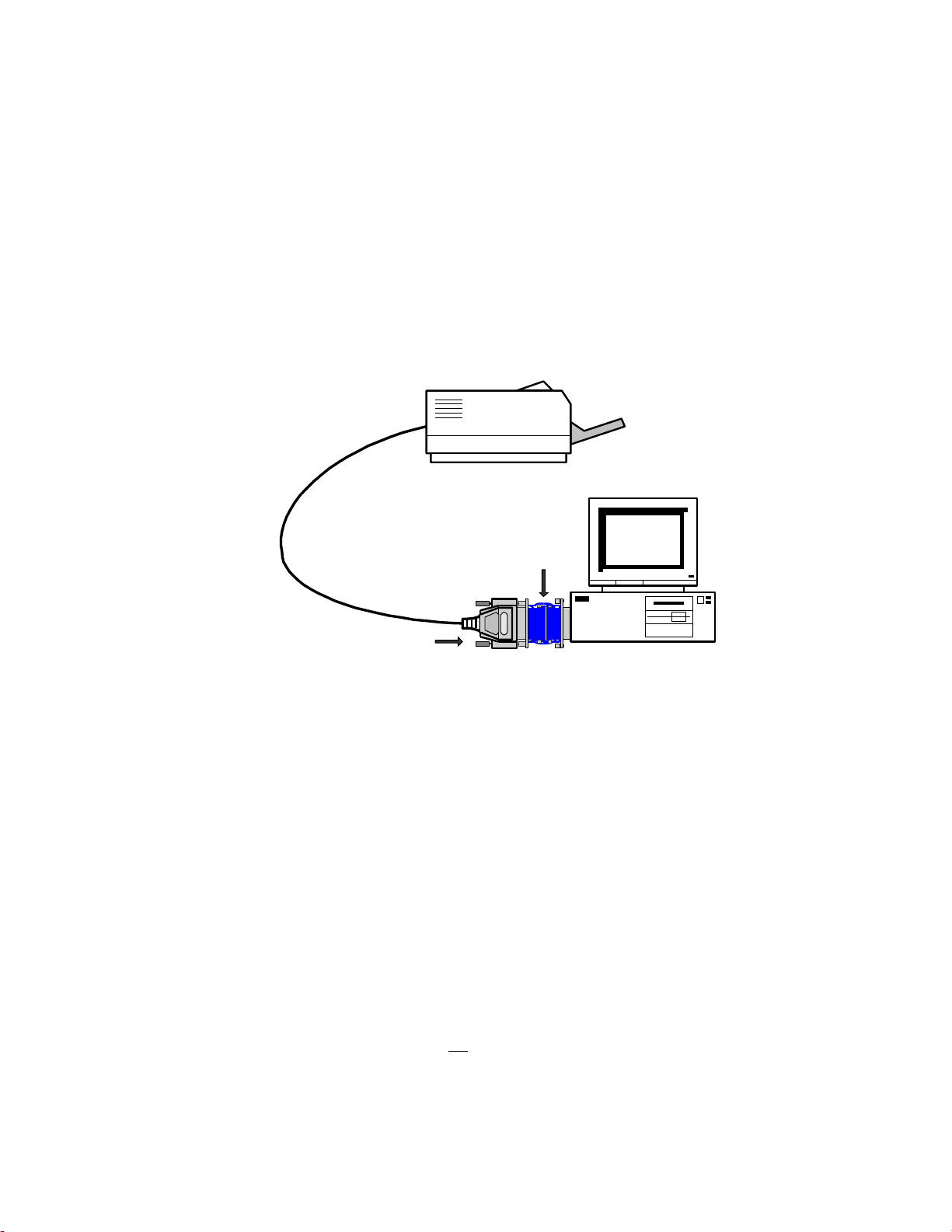
Software Lock Installation
The software lock is a blue adapter connected to the printer port on the TASKE machine and
connected to the telephone switch. The male end of the software lock (the end with pins)
connects to the parallel (printer) port on the back of the TASKE Server or Standalone
machine.
If there is a printer already connected to the printer port on the PC, you must disconnect the
printer, plug the software lock into the printer port, and plug the printer cable into the
female end (end without pins) of the software lock. This setup is illustrated below.
Printer
Software Lock
Printer Cable
TASKE Machine
Important: The software lock (dongle) must remain connected to the TASKE Server as long
as TASKE Call Center Management Tools are being used.
ECP and EPP Parallel Ports
The TASKE ToolBox requires a standard parallel port for the software lock to function
properly. Most Pentium systems include an on-board, high performance Parallel Port
configured through the system's CMOS settings. The following sections discuss the steps
required to configure the hardware and operating system software as a standard parallel port.
Hardware Configuration
To disable extended bidirectional (i.e. ECP port) functionality and force the port to emulate a
standard printer port, you must disable the ECP port functionality through the system's
CMOS settings. Although each system is different, the option can usually be found under
Chipset Features Setup or Peripherals Configuration. Ensure the Port Type or Port Mode
is set to Normal, AT, or SPP. It should not be configured as ECP or EPP.
Note: If you require more information about configuring the port via CMOS settings, refer to
the hardware documentation that came with your computer.
Page 13

________________________ TASKE ToolBox Installation Guide 9
Note: Configuring the hardware alone in Windows 95 may not enable the software lock to
function properly. Configuring the Windows 95 operating system software may be required.
For instructions about how to configure the parallel port under Windows 95, see Appendix B
Note: Bi-directional printers (such as the HP 5 Laserjet series) connected to the software
lock can fool the operating system into thinking the lock is not present. In the event a bidirectional printer printer is connected to the TASKE Server, TASKE recommends that the
bi-directional functionality of the printer be disabled.
Software Installation
Follow the procedure below to install TASKE ACD ToolBox software and the TASKE
database from the TASKE Call Center Management Tools CD-ROM, or from files that have
been downloaded from the TASKE web site.
Before You Begin
To ensure a successful, first-time installation, verify that the TASKE Server has at least 4
GB of free disk space on the target hard drive (for storing TASKE programs and TASKE
data), and have the following items on hand:
• TASKE Call Center Management Tools CD-ROM, or decompressed files from the
TASKE web site.
• Administration floppy disk.
Important: The readme.txt file on the CD-ROM contains important, last-minute
information about TASKE Call Center Management Tools. Before you start the installation
procedure, please review the readme.txt file it can be opened on the CD-ROM using a
text editor.
If You are Upgrading
When you install the TASKE ToolBox, any existing program files are overwritten. Although
the installation procedure has no effect on the TASKE database, it is a good idea to back up
the data if you are about to upgrade from a previous release of TASKE ToolBox software.
Page 14

10 TASKE ToolBox Installation Guide________________________
Installing the TASKE ToolBox Server Software
Note: If you are installing a Network version, you must shut down all TASKE
ToolBox software on each TASKE Client and TASKE Server and install the software
on the TASKE Server first. The ACD Collector must be shutdown before beginning
and the computer must be re-booted when the installation is complete.
1. If you haven’t done so already, install the software lock (dongle) as
illustrated previously.
2. If any applications are running on your computer, close them now.
3. Insert the TASKE Call Center Management Tools CD-ROM and click
Install when the Autorun dialog box opens.
Or
If you have files from the TASKE web site, open the Disk1 directory in the
temporary area on your computer’s local hard drive, then double-click the
Setup.exe program icon.
Once the setup program is launched, the Welcome dialog box appears. This is a reminder
to close any programs currently running on your PC before continuing the installation of the
TASKE Setup program.
4. Choose the Next > button to allow the TASKE ToolBox installation to
proceed.
The Software License Agreement dialog box appears.
Once you have read the Software License Agreement, if you agree, select the Next > button.
5. Once you have read the Software License Agreement, if you agree, select
the Next > button.
The Setup Information dialog box appears. Be sure to read the Setup information, and
follow the directions it contains.
6. Once you have read the Setup Information, select the Next > button.
The Operating System Requirements dialog box appears. Make sure you have the
recommended requirements before continuing with the installation.
7. Once you have read the System Requirements, select the Next > button.
Page 15

________________________ TASKE ToolBox Installation Guide 11
The Select Components dialog box appears as below.
The Select Components dialog box contains drop-down choices for setting up the TASKE
ToolBox components. You will see four choices for the component settings: Server,
Supervisor, Enterprise Supervisor and Agent.
Server: This is the same as Server installation in previous versions. Server is a site that does
the actual collection of the data and all the TASKE Clients are attached to a server.
Supervisor: A Supervisor is equivalent to a TASKE Client, and retains all the functionality
of a client. All the clients are connected to a TASKE server through a network. They can
run Reports, Monitor, Search, etc. over the network. A Supervisor can access the SiteData
and SignData directories of a TASKE server which contain the results from data collection.
Enterprise Supervisor: An Enterprise Supervisor is a Supervisor (Client) that can perform
all the functionality of a Supervisor over an Enterprise network (across multiple sites).
Agent: An Agent only has the permission to run the TASKE Agent Desktop Program over
the network.
By default, the ACD ToolBox and WallSign are installed, and the Voice Toolbox is not.
Select the components you want to install by selecting the checkbox beside the appropriate
component. You also need to choose a service for each selected component.
7. For ACD ToolBox choose Server.
8. For WallSign, choose Server - this will install WallSign Administrator
(formerly Sign Configuration) and WallSign Server (formerly Sign
Machine).
9. If you are installing the Voice Toolbox, click the dialog box. Choose
Server to setup the Server location of the TASKE Voice Toolbox.
Page 16

12 TASKE ToolBox Installation Guide________________________
10. Once you have completed setting your Select Components, select the
Next > button.
The Locate TASKE License Files dialog box appears. You need to provide the Path where
your licensing information resides. By default, the Install program populates the text box
with “a:\” as License Files are shipped on a 3.5” floppy disk.
11. Insert the disk labeled "License Info" into floppy drive A.
12. Once you have completed setting your Licensing Information, select the
Next > button.
The Select Destination Directory dialog box appears. By default, the Destination directory
is populated with c:\taske To change the install to a different directory, click on the Browse
button and choose the directory you would like the TASKE software to be installed in.
When you enter the Path where the files are to be stored, ensure there is plenty of disk space
on the selected drive.
13. Once you have completed setting your Destination directory, select the
Next > button.
The Select SiteData Directory dialog box appears. The Site Data Destination directory is a
shared path located on the network that points to your ACD ToolBox Server PC. This
setting specifies the location of the PBX database, and data files. If the directory is not
specified correctly, client copies of the TASKE ToolBox will not be able to connect to the
TASKE database to receive any real-time or historical information.
This setting by default will be set to a local directory, and should be installed locally, on the
<c:> drive.
14. Enter the path for the SiteData directory. It should be c:\taske\SiteData
To change the path to a different directory, click on the Browse button and choose the
directory your TASKE database and site data are installed in.
15. Once you have completed setting your Site Data Destination directory,
select the Next > button.
The Share SiteData Directory dialog box appears. For clients to connect to the SiteData
directory, the directory must be shared. The TASKE ToolBox install can perform this
function when the directory is created.
16. If you would like the Site Data Destination directory to be shared, select
the Create Share button. When your settings are complete, select the
Next > button.
Page 17

________________________ TASKE ToolBox Installation Guide 13
The Select SignData Directory dialog box appears. The SignData directory is a shared
path located on the network that points to your WallSign Server PC. This setting specifies
the location of the Sign Server configuration files. If the directory is not specified correctly,
client copies of the TASKE WallSign will not be able to connect to the TASKE Sign Server
and configure any readerboards.
This setting by default will be set to a local directory, and should be installed locally, on the
<c:> drive.
17. Enter the path for the SignData directory. It should be c:\taske\SignData
To change the path to a different directory, click on the Browse button and choose the
directory your TASKE database and signdata are installed in.
18. Once you have completed setting your SignData Destination directory,
select the Next > button.
The Share SignData Directory dialog box appears. For clients to connect to the SignData
directory, the directory must be shared. The TASKE ToolBox install can perform this
function when the directory is created.
19. If you would like the Sign Data Destination directory to be shared, select
the Create Share button. When your settings are complete, select the
Next > button.
If you chose to install the TASKE Voice ToolBox, the Select VoiceData Directory dialog box
appears.
The VoiceData directory is a shared path located on the network that points to your TASKE
Voice Server PC. This setting specifies the location of the Voice Server configuration files.
If the directory is not specified correctly, client copies of the TASKE Voice tools will not be
able to connect to the TASKE Voice Server and configure any of the voice channels.
This setting by default will be set to a local directory, and should be installed locally, on the
<c:> drive.
20. Enter the path for the VoiceData directory. It should be
c:\taske\VoiceDataPath
To change the path to a different directory, click on the Browse button and choose the
directory your TASKE voicedata is installed in.
21. Once you have completed setting your VoiceData Destination directory,
select the Next > button.
The Share VoiceData Directory dialog box appears. For clients to connect to the
VoiceData directory, the directory must be shared. The TASKE ToolBox install can perform
this function when the directory is created.
22. If you would like the Voice Data Destination directory to be shared,
select the Create Share button. When your settings are complete,
select the Next > button.
Page 18

14 TASKE ToolBox Installation Guide________________________
The Local Server TCP/IP Settings dialog box appears. Enter the network name and TCP/IP
address of the server machine.
23. Once you have completed setting your local server name and TCP/IP
address, select the Next > button.
The Select SX-2000 PBX data connections settings dialog box appears as below.
You must select the Serial Port for both SMDR and ACD and verify that settings are
identical to your PBX settings.
24. Once you have completed setting your serial ports for SMDR and
ACD, select the Next > button.
If you chose to install a WallSign, the Select WallSign Serial Port Settings dialog box
appears.
25. Once you have completed setting the serial port for the TASKE
WallSign, select the Next > button.
The Select Program Folder dialog box appears. By default, the Setup program creates a
Program Folder called “TASKE ToolBox v7”. You may accept this, create a new folder, or
choose from your Existing Folders List. Choose the name of the Program Group in which
the TASKE ToolBox is to reside.
26. When you have chosen a folder for your TASKE files to reside in, select
the Next > button.
Page 19

________________________ TASKE ToolBox Installation Guide 15
The Start Copying Files dialog box appears. The Start Copying Files dialog box displays
all of the settings that the user has selected in previous screens. These entries are not
editable in this dialog box. If you wish to change any of the settings, click on the < Back
button until you reach the dialog box for the settings you wish to change.
27. If you wish to accept the settings as they are displayed, click the Next >
button.
The File Copying Progress dialog box appears. The File Copying Progress dialog box
displays the progress of the files being installed. You are not prompted for anything during
this process.
The Setup Complete dialog box appears as below.
28. Select the Finish button to complete the installation of the TASKE Setup
program. If you did not receive the patch file Information Dialog Box,
reboot your computer before starting the TASKE software.
Page 20

16 TASKE ToolBox Installation Guide________________________
Chapter 4: ToolBox Installation for
Supervisor/Client
Overview
This chapter describes the options and steps to follow while installing the TASKE ACD
ToolBox client software on a network-connected computer running Windows 95, 98, or NT.
Requirements
TASKE ACD ToolBox client software may be installed on a computer running Microsoft
Windows 95, Windows 98, or Windows NT 4.0 (with Service Pack 3 or later). For optimum
performance, the computer should be equipped with a standard color monitor, mouse,
keyboard, and the following software and hardware (or better):
TASKE ToolBox Hardware Requirements
Operating System Processor: IBM®PC, IBM PS/2 or 100% Compatible
CPU Pentium II - 266 MHz (min)
Required Software Windows 95, 98 or Windows NT 4.0 SP4
Internet Explorer 4.0 or later (required to view Online Help)
Memory (RAM) 32 MB (min)
Monitor Super VGA or Better
Disk Space 4.0 GB (min)
Floppy Drive or
CDRom Drive
Communications Ports 2 RS-232 Communications Ports (Co-Processor such as DIGIBOARD)
Printer Ports 1 Parallel Printer Port
Printer 1 Laser Printer
Mouse Bus , serial, or PS/2 mouse
Network Network Card with Winsock 1.1 compliant TCP/IP Stack
3.5” HDD
4 X CDRom Drive
TASKE Voice ToolBox Hardware Requirements
TASKE ACD ToolBox Version 7
Required Software Windows 95, 98 or Windows NT 4.0 SP4
Internet Explorer 4.0 or later (required to view Online Help)
RAM 32 MB
Disk Space 2.0 GB
Video Super VGA Monitor with PCI Video Card
Network Network card with Winsock 1.1 compliant TCP/IP stack
Page 21

________________________ TASKE ToolBox Installation Guide 17
Computer Pentium II - 266MHz (min), 4 ISA slots
Sound Card SoundBlaster or compatible (for Voice Config)
Voice Card Dialogic D/41D,D/41H, Dialog/4 or D/41E (UK version) See Appendix C
Floppy Drive 3.5” HDD
Communication Ports 2 RS-232 communication ports
Mouse Bus , serial, or PS/2 mouse
Backup Power Supply Mini UPS (for Voice Machine only)
Assumptions
The installation procedure assumes that:
• the TASKE software lock (dongle) is installed on the TASKE Server (see “Installing the
TASKE Software Lock” in Section 3).
• Microsoft file and printer sharing services and TCP/IP network protocol services have
been installed and tested on the client PC (see “Network Considerations” in Section 1).
• a logical network drive has been mapped to the TASKE database (ServerPath directory)
from the Desktop Sign PC (see “Mapping a Network Drive” in Appendix B).
Software Installation
Follow the procedure below to install TASKE ACD ToolBox client software from the
TASKE Call Center Management Tools CD-ROM, or from files that have been downloaded
from the TASKE web site.
Before You Begin
To ensure a successful, first-time installation, have the following items on hand:
• TASKE Call Center Management Tools CD-ROM, or decompressed files from the
TASKE web site.
• Administration floppy disk.
Important: The readme.txt file on the CD-ROM contains important, last-minute
information about TASKE Call Center Management Tools. Before you start the installation
procedure, please review the readme.txt file it can be opened on the CD-ROM using a
text editor.
If You are Upgrading
When you install the TASKE ACD ToolBox client software, any existing program files on
the client PC are overwritten.
Page 22

18 TASKE ToolBox Installation Guide________________________
Installing the TASKE ToolBox Client Software
1. If any applications are running on the client PC, close them now.
2. Insert the TASKE Call Center Management Tools CD-ROM and click
Install when the Autorun dialog box opens.
Or
If you have files from the TASKE web site, open the Disk1 directory in the
temporary area on your computer’s local hard drive, then double-click the
Setup.exe program icon.
If this is a first time installation, or if you are performing an upgrade and the license files
can not be found, you are requested to provide licensing information. If licensing
information is required, the dialog box illustrated below appears.
You need to provide the Path where your licensing information resides.
3. Insert the disk labeled "License Info" into floppy drive A.
4. Type the drive letter A:\.
5. Select the Next > button.
Note If you are not presented with the screen illustrated above, then the TASKE software
has already read your licensing information from the previous installation and lets you
proceed.
The Welcome dialog box appears.
This is a reminder to close any programs currently running on your PC before continuing the
installation of the TASKE Setup program.
Page 23

________________________ TASKE ToolBox Installation Guide 19
6. Choose the Next > button to allow the TASKE ToolBox installation to
proceed.
The Software License Agreement dialog box appears.
7. Once you have read the Software License Agreement, if you agree,
select the Next > button.
The Setup Information dialog box appears. Be sure to read the Setup information, and
follow the directions it contains.
8. Once you have read the Setup Information, select the Next > button.
The Operating System Requirements dialog box appears. Make sure you have the
recommended requirements before continuing with the installation.
9. Once you have read the System Requirements, select the Next > button.
The Select Components dialog box appears as below.
The Select Components dialog box contains drop-down choices for setting up the TASKE
ToolBox components. You will see four choices for the component settings: Server,
Supervisor, Enterprise Supervisor and Agent.
Server: This is the same as Server installation in previous versions. Server is a site that does
the actual collection of the data and all the TASKE Clients are attached to a server.
Page 24

20 TASKE ToolBox Installation Guide________________________
Supervisor: A Supervisor is equivalent to a TASKE Client, and retains all the functionality
of a client. All the clients are connected to a TASKE server through a network. They can
run Reports, Monitor, Search, etc. over the network. A Supervisor can access the SiteData
and SignData directories of a TASKE server which contain the results from data collection.
Enterprise Supervisor: An Enterprise Supervisor is a Supervisor (Client) that can perform
all the functionality of a Supervisor over an Enterprise network (across multiple sites).
Agent: An Agent only has the permission to run the TASKE Agent Desktop Program over
the network.
By default, the ACD ToolBox and WallSign are installed, and the Voice Toolbox is not.
Select the components you want to install by selecting the checkbox beside the appropriate
component. You also need to choose a service for each selected component.
10. For ACD ToolBox choose Supervisor.
11. For WallSign, choose Client.
12. If you are installing the Voice Toolbox, click the dialog box. Choose
Client to setup the TASKE Voice Toolbox.
13. Once you have completed setting your Select Components, select the
Next > button.
The Select Destination Directory dialog box appears. By default, the Destination directory
is populated with c:\taske To change the install to a different directory, click on the Browse
button and choose the directory you would like the TASKE software to be installed in.
When you enter the Path where the files are to be stored, ensure there is plenty of disk space
on the selected drive.
13. Once you have completed setting your Destination directory, select the
Next > button.
The Select SiteData Directory dialog box appears. The Site Data Destination directory is a
shared path located on the network that points to your ACD ToolBox Server PC. This
setting specifies the location of the PBX database, and data files. If the directory is not
specified correctly, client copies of the TASKE ToolBox will not be able to connect to the
TASKE database to receive any real-time or historical information.
14. This setting should be \\“NameofTaskeServerMachine”\SiteData
To change the path to a different directory, click on the Browse button and choose the
directory your TASKE database and site data are installed in.
15. Once you have completed setting your Site Data Destination directory,
select the Next > button.
Page 25

________________________ TASKE ToolBox Installation Guide 21
The Select SignData Directory dialog box appears. The SignData directory is a shared
path located on the network that points to your WallSign Server PC. This setting specifies
the location of the Sign Server configuration files. If the directory is not specified correctly,
client copies of the TASKE WallSign will not be able to connect to the TASKE Sign Server
and configure any readerboards.
16. This setting should be \\“NameofTaskeServerMachine”\SignData
To change the path to a different directory, click on the Browse button and choose the
directory your TASKE database and site data are installed in.
17. Once you have completed setting your Sign Data Destination directory,
select the Next > button.
If you chose to install the TASKE Voice ToolBox, the Select VoiceData Directory dialog box
appears.
The VoiceData directory is a shared path located on the network that points to your TASKE
Voice Server PC. This setting specifies the location of the Voice Server configuration files.
If the directory is not specified correctly, client copies of the TASKE Voice tools will not be
able to connect to the TASKE Voice Server and configure any of the voice channels.
18. Enter the path for the VoiceData directory. It should be
\\“NameofTaskeServerMachine”\VoiceDataPath
To change the path to a different directory, click on the Browse button and choose the
directory your TASKE voice data is installed in.
19. Once you have completed setting your VoiceData Destination
directory, select the Next > button.
The Enter computer’s TCP/IP settings dialog box appears as below.
Page 26

22 TASKE ToolBox Installation Guide________________________
The computer’s TCP/IP setting specifies the name of the computer, and its TCP/IP address.
Enter the name and TCP/IP address of the TASKE Server. If you enter the incorrect
information, or are not sure of the information, click the “Auto Detect” button. This will
force the TASKE ToolBox setup to find the correct information before proceeding.
20. Once you have completed setting your Server Name and TCP/IP
address, select the Next > button.
If you chose to install a Wallsign, the Remote Wall Sign Server TCP/IP settings dialog box
appears.
21. Once you have completed setting your WallSign Server Name and
TCP/IP address, select the Next > button.
If you chose to install the Voice ToolBox, the Remote Voice Server TCP/IP settings dialog
box appears.
22. Once you have completed setting your Voice Server Name and
TCP/IP address, select the Next > button.
The Select Program Folder dialog box appears. By default, the Setup program creates a
Program Folder called “TASKE ToolBox v7”. You may accept this, create a new folder, or
choose from your Existing Folders List. Choose the name of the Program Group in which
the TASKE ToolBox is to reside.
23. When you have chosen a folder for your TASKE files to reside in,
select the Next > button.
The Start Copying Files dialog box appears. The Start Copying Files dialog box displays
all of the settings that the user has selected in previous screens. These entries are not
editable in this dialog box. If you wish to change any of the settings, click on the < Back
button until you reach the dialog box for the settings you wish to change.
24. If you wish to accept the settings as they are displayed, click the Next >
button.
The File Copying Progress dialog box appears. The File Copying Progress dialog box
displays the progress of the files being installed. You are not prompted for anything during
this process.
Page 27

________________________ TASKE ToolBox Installation Guide 23
The Setup Complete dialog box appears as below.
25. Select the Finish button to complete the installation of the TASKE
Setup program. If you did not receive the patch file Information Dialog
Box, reboot your computer before starting the TASKE software.
Page 28

24 TASKE ToolBox Installation Guide________________________
Appendix A: PBX Programming
PBX programming is required for both the TASKE ToolBox and the TASKE Voice
ToolBox.
TASKE ToolBox PBX Configuration Overview
The TASKE ACD ToolBox Overview is intended to show you the necessary hardware
connectivity and programming for the MITEL SX-2000 PBX. The PBX must be
programmed with specific settings in order for the TASKE Software to receive the necessary
SMDR and ACD Real-time data records.
The hardware requirements for connectivity with the SX-2000 are as follows.
• a TASKE PC with 2 Available Comports 2 RS-232 Cables
• an Asynchronous Dataset for SMDR Data Records i.e. 1100 or 2100 series
• an Asynchronous Dataset for ACD RT Data Records i.e. 1100 or 2100 series
• an SX-2000 PBX with a DNIC Line Card running with the ACD Option
The TASKE PC must have 2 comports available in order to allow the two RS-232
connections to be made. One comport is used for SMDR records and the other for the ACD
Real-time Event records.
MITEL SX-2000 Connectivity
FIGURE 1-1: SX-2000 Connectivity, shows the connections between the MITEL SX-2000®
PBX and the TASKE PC.
FIGURE 1-1: SX-2000 Connectivity
Page 29

________________________ TASKE ToolBox Installation Guide 25
Appendix B: Networking Issues
Configuring Microsoft Software
This appendix provides guidelines for setting up and configuring PCs on a Microsoft
Network to support TASKE Call Center Management Tools. Although every attempt has
been made to provide accurate instructions, this appendix is provided as a courtesy
supplement (not a replacement) to the Microsoft operating system documentation, and as
such, this appendix may contain unintentional omissions or inaccuracies.
If you are in doubt, consult the Microsoft documentation or Microsoft Online Help. If you
experience a problem configuring the Windows operating system or setting up your
Microsoft Network, please contact your network administrator or Microsoft Technical
Support directly.
Configuring a Parallel Port Under Windows 95
1. Select Settings:Control Panel, and then choose System.
2. On the Device Manager tab, select the printer port.
3. On the Driver tab, choose the Change Driver button.
4. Choose the Show All Devices option.
5. In the Manufacturers box, click Standard Port Types.
6. In the Models box, click Printer Port, and then click OK.
Note: In the next Step, you will be prompted for the Windows 95 CD-ROM. If
you aren’t prompted for the Windows 95 CD-ROM, reconfigure the ECP
port as a standard port using the computer’s CMOS settings as described
above.
7. When prompted for the Windows 95 CD-ROM:
i) Insert the CD-ROM in the drive.
ii) Specify the following path to the Lpt.vxd file:
<cd-rom drive>:\drivers\printers\1pt
Note: If you don’t have a Windows 95 CD-ROM, you can obtain the required
Lpt.vxd file from the Microsoft Windows 95 Service Pack 1.
8. Click OK.
Page 30

26 TASKE ToolBox Installation Guide________________________
9. Verify that the Lpt.vxd file is version 4.00.503 or higher (double-click the
port in Device Manager, and then click the Device tab). If the Lpt.vxd file
is version 4.00.950, you will have to complete the following steps to copy
the Lpt.vxd file to the Windows System folder manually.
i) In Windows Explorer, navigate to the Windows System folder.
ii) Rename the existing Lpt.vxd file to Lpt.xxx.
iii) Drag the Lpt.vxd file from the Drivers\Printer\Lpt folder on the
Windows 95 CD-ROM to the Windows System folder on your computer.
10. Check the Resources tab in Printer Port properties to verify that the
settings are correct:
If the Direct Memory Access value is displayed for a setting, clear the
Use Automatic Settings option, and then change the value in the
Settings Based On box until the Direct Memory Access value is no
longer displayed. When you are prompted to confirm that you have
modified the settings manually, click Yes.
11. When you are prompted to restart your computer, restart Windows 95.
Adding File & Printer Services under Windows 95/98
If you don’t have file and printer services installed, you might need the Windows 95 or
Windows 98 CD-ROM to complete this procedure.
1. Using the Windows Explorer on the machine that will be used to store
TASKE data, select the Network Neighborhood icon and right-click.
2. Choose Properties. The Network dialog box opens.
3. On the Configuration tab, click Add. The Select Network Component
Type dialog box opens.
4. Select Service and click Add. The Select Network dialog box opens.
5. In the Manufacturers list, select Microsoft.
6. In the Network Services list, click File and Printer Sharing for
Microsoft Windows.
7. Click OK. The Network dialog box is redisplayed with a File and printer
sharing for Microsoft Windows item in the list of installed network
components.
8. Click File and Print Sharing. The File and Print Sharing dialog box
opens.
9. Select the I want to be able to give others access to my files option,
and then click OK.
Page 31

________________________ TASKE ToolBox Installation Guide 27
10. Click OK to close the Network dialog box. The System Settings Change
dialog box opens, prompting you to restart the computer.
11. Click Yes to restart the computer.
Windows 95/98 Sharing and Permissions
To set up taske directory sharing on a Windows 95/98 PC:
1. Using the Windows Explorer on the machine that will be used to store
TASKE data, select the taske directory and right-click.
2. Choose Properties. The Properties sheet for the selected directory
opens.
3. On the Sharing tab, select the Shared As option.
4. In the Share Name box, type a name that will be used to identify the share
assignment (also known as a share name). For example, “TASKE-
PBXdatabase”. Make a note of whichever share name you use, as you will
need it later on when you map a network drive to this computer from
another networked computer.
5. In the Name list, select The World and then click Edit. The Change
Access Rights dialog box opens.
6. Verify that the Full Access Rights option is selected, then click OK.
7. Click Apply and then OK to close the ServerPath directory’s Property
sheet.
To set Windows 95 file/directory permissions on the taske
subdirectories:
1. Double-click the taske directory.
2. In the right pane, select the ACD, LOGS, and SMDR subdirectories, and
then right-click.
3. Choose Properties. A Properties sheet that is common to the selected
directories opens.
4. In the Attributes area on the General tab, select the Read-only option.
5. Click Apply and then click OK.
Page 32

28 TASKE ToolBox Installation Guide________________________
Windows NT Sharing and Permissions
To set up taske directory sharing on a Windows NT PC:
1. Using the Windows NT Explorer on the machine that will be used to store
TASKE data, select the ServerPath directory and choose
File:Properties. The property sheet for the ServerPath directory opens.
2. Click the Sharing tab.
3. Select the Share As option, and in the Share Name box, type a name
that you will use to identify the share assignment (also known as a share
name). For example, “TASKE-PBXdatabase”. Make a note of whichever
share name you use, as you will need it later on when you map a network
drive to this computer from another networked computer.
4. Click Permissions. The Access Through Share Permissions dialog
box opens.
5. In the Name list, verify that Everyone is permitted Full Control. If a
different value is displayed, select Full Control in the Type of Control
box.
6. Click OK to close the Access Through Share Permissions dialog box.
7. Click Apply and then click OK to close the ServerPath directory’s
Property sheet.
To set Windows NT file/directory permissions on the taske
subdirectories:
1. Double-click the ServerPath directory.
2. Select the User subdirectory and right-click.
3. Choose Properties.
4. On the Security tab, click the Permissions button. The Directory
Permissions dialog box opens.
5. Verify that the Replace Permissions on Existing Files option is
selected.
6. Select the line corresponding to Everyone.
7. In the Type of Access box, choose Special Directory Access.
8. In the Special Directory Access dialog box, select the Read option
clear all other options.
9. Click OK until all dialog boxes have been closed.
10. Select the ACD subdirectory and right-click.
Page 33

________________________ TASKE ToolBox Installation Guide 29
11. Repeat Steps 3 through 7 for the ACD subdirectory.
12. In the Special Directory Access dialog box, select the Read option and
the Write option clear all other options.
13. Click OK until all dialog boxes have been closed.
14. Repeat Steps 10 through 13 for the LOGS and SMDR subdirectories.
Mapping a Network Drive
All network-connected PCs running TASKE software need access to the TASKE database.
When you install TASKE software on a network-connected PC, you are required to specify
where the TASKE data files reside.
When you installed the TASKE ACD ToolBox, you defined the ServerPath, which points to
the TASKE database. The procedure below explains how to map a network drive to the
ServerPath directory.
Perform this procedure on the PC requiring access to the TASKE database.
To map a drive to the taske directory:
1. Using Windows Explorer, choose Tools:Map Network Drive. The Map
Network Drive dialog box opens.
2. In the Drive box, select an unused, logical drive letter (e.g. T).
3. In the Path box, enter the logical network node name of the computer
where the TASKE data resides and include the share name that you
assigned previously to the ServerPath directory (e.g.
\\TASKEFILESERVER\TASKE-PBXdatabase).
4. Select the Reconnect at Logon option.
5. Click OK.
Page 34

30 TASKE ToolBox Installation Guide________________________
Appendix C: Voice ToolBox PBX
Configuration
Mitel SX-2000
A recorded announcement device (RAD) is customer supplied equipment that connects to
the SX-2000 system by an on-premise line card (ONS) or an off-premise line card (OPS).
Each RAD requires a port, a directory number, and its own class of service. The number of
RADs in a system depends upon the number of announcements required by the customer.
When the RAD detects ringing, (supplied by the SX-2000 system to the RAD’s Tip and Ring
leads) it closes the loop to signal that it has answered. Once the message is played, the RAD
clears down and opens the loop.
Up to 50 callers can listen to one RAD at the same time. Any caller routed to a busy RAD is
camped-on until the recording is finished. When it clears down, the RAD is seized and all
camped-on callers receive the announcement. All calls maintain their position in the
incoming queue while either listening to the RAD or queued for its service.
RADs can be shared between Hunt Groups (Agents). This is beneficial to a company that
supplies a general first level announcement, and a specific second level announcement for
individual departments.
RAD Groups
RAD groups provide a method whereby a site can be configured with multiple copies of any
given recorded message. When an incoming call is connected to a RAD and one of the RAD
messages is already playing, one of the other RAD messages can be connected so that no
delay is introduced. This ensures that all incoming calls receive a message within n
(maximum delay time programmed in the Hunt Group form) seconds of a request being
received. When a call comes into a RAD group, all members of the group are checked to
determine if there is a RAD available to connect to the caller. The request message identifies
the Hunt Group and includes the Pilot number.
RAD Programming
This section describes RAD programming and the method of setting up a RAD maintenance
telephone.
Note Many aspects of customer data entry for RADs are common to all ANSWER PLUS,
MCD features.
Complete the following steps to set up a RAD maintenance telephone.
Page 35

________________________ TASKE ToolBox Installation Guide 31
1. Assign a directory number for each RAD device using the ONS/OPS
Circuit Descriptor Assignment form.
2. Assign a separate class of service (COS) to each RAD using the Class of
Service Options Assignment form. For each RAD COS, set the following
options.
• Recorded Announcement Device = yes
• ANSWER PLUS Message Length Timer equal to maximum recorded
message duration
• ANSWER PLUS Expected Offhook Timer equal to the message length
timer plus an allowance of two seconds guard time
• assign an appropriate COS assigned to each RAD directory number
using the Station Service Assignment form
3. Program MCD features that require RAD directory numbers, such as
‘Attendant Overflow’ and ‘Front End Messaging’, as the system ‘Reroute
Always’ and ‘System Reroute First Alternate’ destinations.
Note Although RAD and RAD Group directory numbers appear in the system reroute
assignment form, any rerouting programmed against these directory numbers is ignored.
Hunt Group Assignment Form
A RAD Hunt Group is a group of RADS assigned Extension numbers using customer data
entry forms (CDE). Hunt Groups are created through the Hunt Group Assignment form as
follows.
1. Program a Hunt Group with a Group Type of RAD. The RAD1, RAD2, and
Night RAD fields can be ignored, as they do not apply to a RAD Hunt
Group.
2. Program the directory numbers for each RAD within the Hunt Group.
Path Assignment Form
This form is used to configure ACD Paths. The Path contains the information necessary to
control an incoming call through the ACD system. It specifies the resources used, the order
in which they are encountered, and the timing of the steps.
Form Headings
The Path Directory Number field is similar to the Hunt Group number in the system. Enter
a number from 1 to 7 digits in length.
The Path Reporting Number is a mandatory, programmable field that specifies the Path
number of the Agent Group. It is a required field for SMDR. The Path reporting number
must also be unique. Enter a 3-digit number in the range of 1 to 999.
Page 36

32 TASKE ToolBox Installation Guide________________________
The Path Name is a read-only field that displays the telephone directory name for the Path
directory number. This field is up to 20 characters long.
The Option heading displays the list of available Path options.
The Value heading requires values as described below.
Conditions
• RADs and RAD groups as interflow point directory numbers are treated as auto-
attendants.
• RADs and RAD groups programmed as Path unavailable answer points are treated as
night RADs.
Path Assignment Options
The Path Assignments Options are listed in the table below.
Path Assignment Options
Options Description
Recording 1:Delay to
Start Time
Recording 1:Directory
Number
Recording 2:Delay to
Start Time
Recording 2:Directory
Number
Recording 3 and
Recording 4
Repeat Last Recording
Enabled
Last Recording Repeat
Interval
Enter the delay time in the range of 00:00 to 54:00
(minutes:seconds). This field specifies when recording 1
starts relative to when the caller enters the Path.
Enter a number 1 to 7 digits in length. This number must
be the directory number of a RAD or RAD group.
Enter a delay time in the range of 00:00 to 54:00
(minutes:seconds).
Enter a number 1 to 7 digits in length. This number must
be the directory number of a RAD or RAD group.
Enter a number 1 to 7 digits in length. This number must
be the directory number of a RAD or RAD group.
Enter Yes or No. Yes causes the last programmed
recording in the Path to play indefinitely (while the caller
is queued) with the interval time as specified in the next
field (last recording repeat interval).
This field is mandatory if Yes is specified in the Last
Recording Enabled field. Enter a time in the range of
00:00 to 54:00 (minutes:seconds).
Interflow Point Directory
Number
Specifies the directory number of the interflow
destination. Valid interflow destinations are stations,
attendant consoles, ACD Paths, Hunt Groups, system
Page 37

________________________ TASKE ToolBox Installation Guide 33
speed calls, RADs and RAD groups. RADs and RAD
groups as interflow point directory numbers are treated as
auto-attendants. Note : If this field is left blank and
interflow is enabled, the caller will be dropped.
Path Unavailable Answer
Point Directory Number
Specifies the directory number of the destination that new
ACD calls are routed when the Path is unavailable. Valid
destinations are stations, attendant consoles, ACD Paths,
Hunt Groups, system speed calls, RADs and RAD groups.
RADs and RAD groups as interflow point directory
numbers are treated as auto-attendants. If this field is not
programmed, the default handling for an unavailable Path
is to drop external callers, and restart internal callers.
Points to Remember
As a final note for the SX-2000, the Feature Access Code for Remove Do Not Disturb (DND)
must be known before the TASKE Voice ToolBox can use the Auto Remove RAD DND
feature.
To remove a RAD port from DND mode, the Voice Machine uses a user-specified DND Dial
String, unique to each channel. This Dial String is composed of the Feature Access Code for
Remove DND plus the 4-digit directory number for the RAD port.
When the Voice Machine attempts to remove a RAD port from DND mode, it takes the
channel off hook and dials the DND Dial String. The channel is then available for calls.
The DND Dial String must be specified by the user in the Voice Config application.
Without the correct dial string, the ports are not automatically removed from DND mode.
Installing Dialogic Boards
The TASKE Voice ToolBox currently supports the following four models of Dialogic Voice
Boards.
• D/41D (full-size card)
• D/41H (half-size card)
• Dialog/4 (half-size card)
• D/41E (UK full-size card)
The installation procedures are the same for the D/41D, D/41H, and Dialog/4, while the
D/41E requires different installation procedures.
Page 38

34 TASKE ToolBox Installation Guide________________________
Dialogic D/41D, D/41H, and Dialog/4
The following steps provide a quick overview of the Quick Installation card.
Note If you have purchased the D/41D card, make certain there is enough space in the
computer's case for the card and ensure there is not interfere with the proper cooling of the
CPU. A Quick Installation card is included with both versions of the Dialogic voice cards
and should be read carefully. The reference card explains how to configure and install the
voice card in a PC.
1. If you are installing 1 voice card, ensure that JP7 has a jumper installed
across its two pins. If you are installing multiple voice cards, remove
jumper JP7 from all but one of the voice cards.
2. The D/41D and D/41H voice cards require a single hardware interrupt
request line (IRQ), with the default being IRQ 3.
The table below outlines Jumper JP1 sets the IRQ, as well as the computer resource which
typically uses each IRQ. Before attempting to use an IRQ for the voice card, verify that the
IRQ is not being used by another card in the system.
IRQ Settings
Pin Position IRQ Resource
1 2/9 Video card
2 3
(default)
3 4 COM 1
4 5 LPT2 / Sound
5 6 Floppy Disk
6 7 LPT1
3. Each voice card requires a section of the computer's upper memory for
proper functioning. To set the memory upper address for a card, both the
base memory address and the offset memory address must be specified.
4. To set the base memory address, set jumpers JP5 and JP6 to one of the
base addresses listed in the table below.
COM 2
Base Memory Addresses
JP5 JP6 Base Memory
Address
out out D0000H (default)
in out A0000H
Page 39

________________________ TASKE ToolBox Installation Guide 35
out in C0000H
in in B0000H
5. To set the offset memory address, set the dip switches at SW1 to one of
the offset addresses listed in the table below.
Offset Memory Addresses
SW 1
1 2 3
off off off 0000H
off off on 2000H
off on off 4000H
off on on 6000H
on off off 8000H
on off on A000H
on on off C000H
on on on E000H
6. To determine which upper memory address the board is using, simply add
the base and offset memory addresses together.
Offset Memory
Address
For example, if the base memory address is D0000H (H means hexadecimal) and the offset
memory address is 8000H, then the upper memory address being used is D8000H.
7. Verify that other cards in your system are not using the same upper
memory address as the voice cards.
Note The memory address range from D0000H to DFFFFH is usually free, but other cards
may attempt to use memory addresses within that range.
In addition, recall that each voice card must use a unique upper memory address. Each card
can, however, use consecutive memory addresses.
Page 40

36 TASKE ToolBox Installation Guide________________________
For example, a system could have four D/41D, Dialog/4, or D/41H voice cards with the
following addresses: D0000H, D2000H, D4000H, and D6000H. However, if a network card
uses memory address D6000H, the voice card at that memory address would have to be
moved to another address (i.e. DA000H, DC000H, or DE000).
Dialogic D/41E
The D/41E voice card comes as a full length card. Make certain there is enough space in the
computer's case for the card and ensure it does not interfere with the proper cooling of the
CPU.
A Quick Installation instruction card is included with the D/41E card. It should be read
carefully. The reference card explains how to configure and install the voice card in a PC.
Select a unique board ID number for each voice card by turning the rotary switch SW1 to the
desired hexadecimal number. The numbers range from 0H to FH (0 to 15 in decimal).
All D/41E voice cards share IRQ 3 and upper memory address D0000H. Therefore, before
attempting to use these cards, it is important to verify that the IRQ and the upper memory
address are not being used by another card in the system.
Installing ONS Ports from the PBX
The TASKE Voice ToolBox requires a separate ONS port connected to each channel of each
Dialogic Voice Card that is to be used as a RAD.
D/41D, Dialog/4, and D/41H
These voice cards have two RJ-14 jacks on the back of the card. Each RJ-14 jack provides a
connection for two voice channels as illustrated in the table below.
D/41E
The voice card has four RJ-11 jacks on the back of the card. Each RJ-11 jack provides a
connection for a single voice channel as illustrated below.
Page 41

________________________ TASKE ToolBox Installation Guide 37
Voice Jack Connections
D/41D and D/41H D/41E
 Loading...