

Page 1

GENERAL INFORMATION GUIDE
LIGHTWARE 19, RELEASE 3.1
Page 2

NOTICE
The information contained in this document is believed to be accurate in all respects
‚
but is not warranted by Mitel Networks Corporation (MITEL
). The information is
subject to change without notice and should not be construed in any way as a
commitment by Mitel or any of its affiliates or subsidiaries. Mitel and its affiliates and
subsidiaries assume no responsibility for any errors or omissions in this document.
Revisions of this document or new editions of it may be issued to incorporate such
changes.
SX-200, SX-2000, SUPERSET, ACD TELEMARKETER, SUPERCONSOLE 1000, MILINK,
TALK TO, SMART-1, NuPoint Messenger, Mitel Express Messenger, and LIGHTWARE are
trademarks of Mitel Networks Corporation.
VT100 is a trademark of Digital Equipment Corporation
IBM
,
IBM PC and IBM AT are trademarks of International Business Machines Corporation
Windows is a trademark of Microsoft Corporation
CENTREX is a trademark of Western Electric Company.
Other product names mentioned in this document may be trademarks of their respective
companies and are hereby acknowledged.
SX-200 EL/SX-200 ML General Information Guide
LIGHTWARE 19, Release 3.1
50003510, Revision A
February 2003
®,™ Trademark of Mitel Networks Corporation
©Copyright 2003, Mitel Networks Corporation
All rights reserved
Page 3

Table of Contents
Product Overview. . . . . . . . . . . . . . . . . . . . . . . . . . . . . . . . . . . . . . . . . . . . . . . . . . . . . . . . . . . . . 1
History . . . . . . . . . . . . . . . . . . . . . . . . . . . . . . . . . . . . . . . . . . . . . . . . . . . . . . . . . . . . . . . . . . 1
The Theme - Flexibility, Reliability, Usability . . . . . . . . . . . . . . . . . . . . . . . . . . . . . . . . . . . . . 4
SX-200
®
EL System . . . . . . . . . . . . . . . . . . . . . . . . . . . . . . . . . . . . . . . . . . . . . . . . . . . . . . . . 5
SX-200 ML System . . . . . . . . . . . . . . . . . . . . . . . . . . . . . . . . . . . . . . . . . . . . . . . . . . . . . . . . 7
SX-200 ELx Cabinet . . . . . . . . . . . . . . . . . . . . . . . . . . . . . . . . . . . . . . . . . . . . . . . . . . . . . . . 8
SX-200 LIGHT Peripheral Cabinet . . . . . . . . . . . . . . . . . . . . . . . . . . . . . . . . . . . . . . . . . . . . 9
SX-200 SPINE Peripheral Bay . . . . . . . . . . . . . . . . . . . . . . . . . . . . . . . . . . . . . . . . . . . . . . 10
SX-200 IP Node . . . . . . . . . . . . . . . . . . . . . . . . . . . . . . . . . . . . . . . . . . . . . . . . . . . . . . . . . . 11
SX-200 EL/ML Peripheral Devices . . . . . . . . . . . . . . . . . . . . . . . . . . . . . . . . . . . . . . . . . . . 13
Voice Capabilities . . . . . . . . . . . . . . . . . . . . . . . . . . . . . . . . . . . . . . . . . . . . . . . . . . . . . . 14
Data Capabilities . . . . . . . . . . . . . . . . . . . . . . . . . . . . . . . . . . . . . . . . . . . . . . . . . . . . . . 19
Supporting Applications. . . . . . . . . . . . . . . . . . . . . . . . . . . . . . . . . . . . . . . . . . . . . . . . . . . . . . 21
Voice over IP (VoIP) . . . . . . . . . . . . . . . . . . . . . . . . . . . . . . . . . . . . . . . . . . . . . . . . . . . . . . 21
Business/Commercial/Institutional . . . . . . . . . . . . . . . . . . . . . . . . . . . . . . . . . . . . . . . . . . . . 21
Hotel/Motel . . . . . . . . . . . . . . . . . . . . . . . . . . . . . . . . . . . . . . . . . . . . . . . . . . . . . . . . . . . . . . 21
Assisted Living . . . . . . . . . . . . . . . . . . . . . . . . . . . . . . . . . . . . . . . . . . . . . . . . . . . . . . . . . . . 22
Call Management . . . . . . . . . . . . . . . . . . . . . . . . . . . . . . . . . . . . . . . . . . . . . . . . . . . . . . . . . 23
ACD TELEMARKETER
®
Application . . . . . . . . . . . . . . . . . . . . . . . . . . . . . . . . . . . . . . . . . . 23
Automated Attendant . . . . . . . . . . . . . . . . . . . . . . . . . . . . . . . . . . . . . . . . . . . . . . . . . . . . . . 24
®
MITEL
MyAttendant . . . . . . . . . . . . . . . . . . . . . . . . . . . . . . . . . . . . . . . . . . . . . . . . . . . . . . 24
FAX Tone Detection . . . . . . . . . . . . . . . . . . . . . . . . . . . . . . . . . . . . . . . . . . . . . . . . . . . . . . 25
Centralized Attendant . . . . . . . . . . . . . . . . . . . . . . . . . . . . . . . . . . . . . . . . . . . . . . . . . . . . . 25
Centralized Voice Mail . . . . . . . . . . . . . . . . . . . . . . . . . . . . . . . . . . . . . . . . . . . . . . . . . . . . . 25
Tenanting . . . . . . . . . . . . . . . . . . . . . . . . . . . . . . . . . . . . . . . . . . . . . . . . . . . . . . . . . . . . . . . 26
MITEL Application Interface (MAI) Package . . . . . . . . . . . . . . . . . . . . . . . . . . . . . . . . . . . . 26
Data Switching . . . . . . . . . . . . . . . . . . . . . . . . . . . . . . . . . . . . . . . . . . . . . . . . . . . . . . . . . . . 26
NuPoint Messenger™ . . . . . . . . . . . . . . . . . . . . . . . . . . . . . . . . . . . . . . . . . . . . . . . . . . . . . 26
MiteI Express Messenger™ . . . . . . . . . . . . . . . . . . . . . . . . . . . . . . . . . . . . . . . . . . . . . . . . . 27
MITEL TAPI Desktop Software . . . . . . . . . . . . . . . . . . . . . . . . . . . . . . . . . . . . . . . . . . . . . . 27
Mitel Networks™ 6100 Contact Center Solutions . . . . . . . . . . . . . . . . . . . . . . . . . . . . . . . . 28
Mitel Networks 6500 Speech-Enabled Applications . . . . . . . . . . . . . . . . . . . . . . . . . . . . . . 29
ISDN Support . . . . . . . . . . . . . . . . . . . . . . . . . . . . . . . . . . . . . . . . . . . . . . . . . . . . . . . . . . . . 30
Basic Rate Interface Card . . . . . . . . . . . . . . . . . . . . . . . . . . . . . . . . . . . . . . . . . . . . . . . 30
ISDN Primary Rate Interface Card . . . . . . . . . . . . . . . . . . . . . . . . . . . . . . . . . . . . . . . . . 31
ISDN Network Gateway (North America only) . . . . . . . . . . . . . . . . . . . . . . . . . . . . . . . . 33
SX-200 MyAdministrator . . . . . . . . . . . . . . . . . . . . . . . . . . . . . . . . . . . . . . . . . . . . . . . . . . . 33
System Fail Transfer . . . . . . . . . . . . . . . . . . . . . . . . . . . . . . . . . . . . . . . . . . . . . . . . . . . . . . 34
Configuration. . . . . . . . . . . . . . . . . . . . . . . . . . . . . . . . . . . . . . . . . . . . . . . . . . . . . . . . . . . . . . . 35
SX-200 EL System Configuration . . . . . . . . . . . . . . . . . . . . . . . . . . . . . . . . . . . . . . . . . . . . 36
SX-200 EL Control Cabinet . . . . . . . . . . . . . . . . . . . . . . . . . . . . . . . . . . . . . . . . . . . . . . 36
Connecting Peripheral Bays . . . . . . . . . . . . . . . . . . . . . . . . . . . . . . . . . . . . . . . . . . . . . . 41
Connecting SX-200 IP Nodes . . . . . . . . . . . . . . . . . . . . . . . . . . . . . . . . . . . . . . . . . . . . . 43
Maximum Number of T1 Links . . . . . . . . . . . . . . . . . . . . . . . . . . . . . . . . . . . . . . . . . . . . 44
50003510 Revision A iii
Page 4

SX-200 General Information Guide
SX-200 ML System Configuration . . . . . . . . . . . . . . . . . . . . . . . . . . . . . . . . . . . . . . . . . . . . 45
Connecting a Peripheral Bay . . . . . . . . . . . . . . . . . . . . . . . . . . . . . . . . . . . . . . . . . . . . . 48
SX-200 ML (FD) System Configuration . . . . . . . . . . . . . . . . . . . . . . . . . . . . . . . . . . . . . . . . 49
SX-200 RM Peripheral Cabinet . . . . . . . . . . . . . . . . . . . . . . . . . . . . . . . . . . . . . . . . . . . . . . 51
SX-200 LIGHT Peripheral Cabinet . . . . . . . . . . . . . . . . . . . . . . . . . . . . . . . . . . . . . . . . . . . . 52
Peripheral Interface Cards and Modules . . . . . . . . . . . . . . . . . . . . . . . . . . . . . . . . . . . . . . . 53
Digital Control and Digital Services Cards and Modules . . . . . . . . . . . . . . . . . . . . . . . . . . . 55
SX-200 Wall Mount Bracket . . . . . . . . . . . . . . . . . . . . . . . . . . . . . . . . . . . . . . . . . . . . . . . . . 58
SX-200 SPINE Bay . . . . . . . . . . . . . . . . . . . . . . . . . . . . . . . . . . . . . . . . . . . . . . . . . . . . . . . 59
SX-200 SPINE Modules . . . . . . . . . . . . . . . . . . . . . . . . . . . . . . . . . . . . . . . . . . . . . . . . . . . . 60
Power Supplies . . . . . . . . . . . . . . . . . . . . . . . . . . . . . . . . . . . . . . . . . . . . . . . . . . . . . . . . . . 60
Bay Power Supply . . . . . . . . . . . . . . . . . . . . . . . . . . . . . . . . . . . . . . . . . . . . . . . . . . . . . 60
Power Module II . . . . . . . . . . . . . . . . . . . . . . . . . . . . . . . . . . . . . . . . . . . . . . . . . . . . . . . 60
Uninterruptible Power Supply (UPS) . . . . . . . . . . . . . . . . . . . . . . . . . . . . . . . . . . . . . . . 61
System Fail Transfer . . . . . . . . . . . . . . . . . . . . . . . . . . . . . . . . . . . . . . . . . . . . . . . . . . . . . . 61
Peripherals. . . . . . . . . . . . . . . . . . . . . . . . . . . . . . . . . . . . . . . . . . . . . . . . . . . . . . . . . . . . . . . . . 63
Introduction . . . . . . . . . . . . . . . . . . . . . . . . . . . . . . . . . . . . . . . . . . . . . . . . . . . . . . . . . . . . . 63
Mitel Networks 5000 Series IP Phones . . . . . . . . . . . . . . . . . . . . . . . . . . . . . . . . . . . . . . . . 64
Mitel Networks 5201 IP Phone . . . . . . . . . . . . . . . . . . . . . . . . . . . . . . . . . . . . . . . . . . . . 64
Mitel Networks 5010 IP Phone . . . . . . . . . . . . . . . . . . . . . . . . . . . . . . . . . . . . . . . . . . . . 65
Mitel Networks 5020 IP Phone . . . . . . . . . . . . . . . . . . . . . . . . . . . . . . . . . . . . . . . . . . . . 66
Mitel Networks 5215 IP Phone . . . . . . . . . . . . . . . . . . . . . . . . . . . . . . . . . . . . . . . . . . . . 67
Mitel Networks 5220 IP Phone . . . . . . . . . . . . . . . . . . . . . . . . . . . . . . . . . . . . . . . . . . . . 68
Mitel Networks 5305 IP Office Conference Unit . . . . . . . . . . . . . . . . . . . . . . . . . . . . . . . 69
Mitel Networks 5310 IP Board Room Conference Unit . . . . . . . . . . . . . . . . . . . . . . . . . . 70
Attendant Consoles . . . . . . . . . . . . . . . . . . . . . . . . . . . . . . . . . . . . . . . . . . . . . . . . . . . . . . . 71
SUPERCONSOLE 1000
®
Attendant Console . . . . . . . . . . . . . . . . . . . . . . . . . . . . . . . . . 72
SUPERSET™ 7000 Attendant Console . . . . . . . . . . . . . . . . . . . . . . . . . . . . . . . . . . . . . 73
SUPERSET 4000 Series Telephones . . . . . . . . . . . . . . . . . . . . . . . . . . . . . . . . . . . . . . . . . 74
SUPERSET 4001 Telephone . . . . . . . . . . . . . . . . . . . . . . . . . . . . . . . . . . . . . . . . . . . . . 76
SUPERSET 4015 Telephone . . . . . . . . . . . . . . . . . . . . . . . . . . . . . . . . . . . . . . . . . . . . . 77
SUPERSET 4025 Telephone . . . . . . . . . . . . . . . . . . . . . . . . . . . . . . . . . . . . . . . . . . . . . 78
SUPERSET 4090 Telephone . . . . . . . . . . . . . . . . . . . . . . . . . . . . . . . . . . . . . . . . . . . . . 79
SUPERSET 4125 Telephone . . . . . . . . . . . . . . . . . . . . . . . . . . . . . . . . . . . . . . . . . . . . . 80
SUPERSET 4150 Telephone . . . . . . . . . . . . . . . . . . . . . . . . . . . . . . . . . . . . . . . . . . . . . 81
Programmable Key Modules . . . . . . . . . . . . . . . . . . . . . . . . . . . . . . . . . . . . . . . . . . . . . . . . 82
Mitel Networks 5412 Programmable Key Module . . . . . . . . . . . . . . . . . . . . . . . . . . . . . . 82
Mitel Networks 5448 Programmable Key Module . . . . . . . . . . . . . . . . . . . . . . . . . . . . . . 83
Mitel Networks 5410 Programmable Key Module . . . . . . . . . . . . . . . . . . . . . . . . . . . . . . 84
Mitel Networks 5415 Programmable Key Module . . . . . . . . . . . . . . . . . . . . . . . . . . . . . . 85
Mitel Networks Programmable Key Module 12 . . . . . . . . . . . . . . . . . . . . . . . . . . . . . . . . 86
Mitel Networks Programmable Key Module 48 . . . . . . . . . . . . . . . . . . . . . . . . . . . . . . . . 87
Interface Modules . . . . . . . . . . . . . . . . . . . . . . . . . . . . . . . . . . . . . . . . . . . . . . . . . . . . . . . . 88
SUPERSET Interface Module 1 . . . . . . . . . . . . . . . . . . . . . . . . . . . . . . . . . . . . . . . . . . . 88
SUPERSET Interface Module 2 . . . . . . . . . . . . . . . . . . . . . . . . . . . . . . . . . . . . . . . . . . . 89
iv Revision A 50003510
Page 5

Table of Contents
DSS/BLF Interface Unit . . . . . . . . . . . . . . . . . . . . . . . . . . . . . . . . . . . . . . . . . . . . . . . . . . . . 90
Music-On-Hold/Pager Unit (DMP) . . . . . . . . . . . . . . . . . . . . . . . . . . . . . . . . . . . . . . . . . . . . 91
Datasets . . . . . . . . . . . . . . . . . . . . . . . . . . . . . . . . . . . . . . . . . . . . . . . . . . . . . . . . . . . . . . . . 91
DATASET 1103 Standalone . . . . . . . . . . . . . . . . . . . . . . . . . . . . . . . . . . . . . . . . . . . . . . 92
DATASET 2103 Standalone . . . . . . . . . . . . . . . . . . . . . . . . . . . . . . . . . . . . . . . . . . . . . . 93
SMART-1
®
Devices . . . . . . . . . . . . . . . . . . . . . . . . . . . . . . . . . . . . . . . . . . . . . . . . . . . . . . . 94
Digital Line Monitor (DLM) . . . . . . . . . . . . . . . . . . . . . . . . . . . . . . . . . . . . . . . . . . . . . . . . . . 95
MITEL Express Messenger™ Voice Mail . . . . . . . . . . . . . . . . . . . . . . . . . . . . . . . . . . . . . . 95
Auto Attendant Features . . . . . . . . . . . . . . . . . . . . . . . . . . . . . . . . . . . . . . . . . . . . . . . . . 95
Voice Mail Features . . . . . . . . . . . . . . . . . . . . . . . . . . . . . . . . . . . . . . . . . . . . . . . . . . . . 96
NuPoint Messenger Voice Mail . . . . . . . . . . . . . . . . . . . . . . . . . . . . . . . . . . . . . . . . . . . . . . 99
Feature Description. . . . . . . . . . . . . . . . . . . . . . . . . . . . . . . . . . . . . . . . . . . . . . . . . . . . . . . . . 101
Feature Categories. . . . . . . . . . . . . . . . . . . . . . . . . . . . . . . . . . . . . . . . . . . . . . . . . . 102
Abbreviated Dial. . . . . . . . . . . . . . . . . . . . . . . . . . . . . . . . . . . . . . . . . . . . . . . . . . . . 119
Access Codes - Global Find. . . . . . . . . . . . . . . . . . . . . . . . . . . . . . . . . . . . . . . . . . . 119
Account Codes. . . . . . . . . . . . . . . . . . . . . . . . . . . . . . . . . . . . . . . . . . . . . . . . . . . . . 119
Account Codes - Verified . . . . . . . . . . . . . . . . . . . . . . . . . . . . . . . . . . . . . . . . . . . . . 119
Account Codes - Verified (Special DISA). . . . . . . . . . . . . . . . . . . . . . . . . . . . . . . . . 120
Add Held. . . . . . . . . . . . . . . . . . . . . . . . . . . . . . . . . . . . . . . . . . . . . . . . . . . . . . . . . . 120
Analog Networking . . . . . . . . . . . . . . . . . . . . . . . . . . . . . . . . . . . . . . . . . . . . . . . . . . 120
Attendant Abbreviated Dial Number Entry . . . . . . . . . . . . . . . . . . . . . . . . . . . . . . . . 121
Attendant Access (Dial 0). . . . . . . . . . . . . . . . . . . . . . . . . . . . . . . . . . . . . . . . . . . . . 121
Attendant Advisory Message Setup . . . . . . . . . . . . . . . . . . . . . . . . . . . . . . . . . . . . . 121
Attendant Alarm Readout. . . . . . . . . . . . . . . . . . . . . . . . . . . . . . . . . . . . . . . . . . . . . 121
Attendant Automatic Overflow . . . . . . . . . . . . . . . . . . . . . . . . . . . . . . . . . . . . . . . . . 121
Attendant Bell Off . . . . . . . . . . . . . . . . . . . . . . . . . . . . . . . . . . . . . . . . . . . . . . . . . . . 122
Attendant Busy Override . . . . . . . . . . . . . . . . . . . . . . . . . . . . . . . . . . . . . . . . . . . . . 122
Attendant Callback - Busy/No Answer . . . . . . . . . . . . . . . . . . . . . . . . . . . . . . . . . . . 122
Attendant Call Forward Setup and Cancel. . . . . . . . . . . . . . . . . . . . . . . . . . . . . . . . 122
Attendant Call Selection. . . . . . . . . . . . . . . . . . . . . . . . . . . . . . . . . . . . . . . . . . . . . . 122
Attendant Call Splitting and Swapping . . . . . . . . . . . . . . . . . . . . . . . . . . . . . . . . . . . 122
Attendant Calls Forwarded On No Answer. . . . . . . . . . . . . . . . . . . . . . . . . . . . . . . . 122
Attendant Conference. . . . . . . . . . . . . . . . . . . . . . . . . . . . . . . . . . . . . . . . . . . . . . . . 123
Attendant Console Display Language . . . . . . . . . . . . . . . . . . . . . . . . . . . . . . . . . . . 123
Attendant Console Handset and Headset Receiver Volume Control. . . . . . . . . . . . 123
Attendant Console Last Call Retrieve. . . . . . . . . . . . . . . . . . . . . . . . . . . . . . . . . . . . 123
Attendant Console LCD Display. . . . . . . . . . . . . . . . . . . . . . . . . . . . . . . . . . . . . . . . 123
Attendant Console LDN Keys. . . . . . . . . . . . . . . . . . . . . . . . . . . . . . . . . . . . . . . . . . 124
Attendant Console Lockout . . . . . . . . . . . . . . . . . . . . . . . . . . . . . . . . . . . . . . . . . . . 124
Attendant Console Macro Keys . . . . . . . . . . . . . . . . . . . . . . . . . . . . . . . . . . . . . . . . 124
Attendant Console Set Paging - Directed, Group, or All Set . . . . . . . . . . . . . . . . . . 124
Attendant Date and Time Setup. . . . . . . . . . . . . . . . . . . . . . . . . . . . . . . . . . . . . . . . 124
Attendant Default Call Positions. . . . . . . . . . . . . . . . . . . . . . . . . . . . . . . . . . . . . . . . 124
Attendant Destination (DEST) Key. . . . . . . . . . . . . . . . . . . . . . . . . . . . . . . . . . . . . . 125
Attendant Directed Call Pickup. . . . . . . . . . . . . . . . . . . . . . . . . . . . . . . . . . . . . . . . . 125
Attendant Direct Trunk Select. . . . . . . . . . . . . . . . . . . . . . . . . . . . . . . . . . . . . . . . . . 125
Attendant DISA Code Setup. . . . . . . . . . . . . . . . . . . . . . . . . . . . . . . . . . . . . . . . . . . 125
Attendant Do Not Disturb (DND) Setup, Cancel or Override . . . . . . . . . . . . . . . . . . 125
Attendant Emergency Call (911) Detection . . . . . . . . . . . . . . . . . . . . . . . . . . . . . . . 125
Attendant Extension Busy-Out . . . . . . . . . . . . . . . . . . . . . . . . . . . . . . . . . . . . . . . . . 125
Attendant Flash Over Trunk . . . . . . . . . . . . . . . . . . . . . . . . . . . . . . . . . . . . . . . . . . . 125
50003510 Revision A v
Page 6

SX-200 General Information Guide
Attendant Function Access. . . . . . . . . . . . . . . . . . . . . . . . . . . . . . . . . . . . . . . . . . . . 126
Attendant Hold Positions . . . . . . . . . . . . . . . . . . . . . . . . . . . . . . . . . . . . . . . . . . . . . 126
Attendant Implicit New Call. . . . . . . . . . . . . . . . . . . . . . . . . . . . . . . . . . . . . . . . . . . . 127
Attendant Individual Directory Number. . . . . . . . . . . . . . . . . . . . . . . . . . . . . . . . . . . 127
Attendant Interposition Calling and Transfer . . . . . . . . . . . . . . . . . . . . . . . . . . . . . . 127
Attendant Lockout Alarm . . . . . . . . . . . . . . . . . . . . . . . . . . . . . . . . . . . . . . . . . . . . . 127
Attendant Message Waiting Setup and Cancel . . . . . . . . . . . . . . . . . . . . . . . . . . . . 127
Attendant Multi-New Call Tone. . . . . . . . . . . . . . . . . . . . . . . . . . . . . . . . . . . . . . . . . 128
Attendant New Call Ring . . . . . . . . . . . . . . . . . . . . . . . . . . . . . . . . . . . . . . . . . . . . . 128
Attendant Night/Day Switching. . . . . . . . . . . . . . . . . . . . . . . . . . . . . . . . . . . . . . . . . 128
Attendant Paging Access . . . . . . . . . . . . . . . . . . . . . . . . . . . . . . . . . . . . . . . . . . . . . 128
Attendant Paged Hold Access . . . . . . . . . . . . . . . . . . . . . . . . . . . . . . . . . . . . . . . . . 128
Attendant Serial Call. . . . . . . . . . . . . . . . . . . . . . . . . . . . . . . . . . . . . . . . . . . . . . . . . 129
Attendant Source Key. . . . . . . . . . . . . . . . . . . . . . . . . . . . . . . . . . . . . . . . . . . . . . . . 129
Attendant Timed Recall . . . . . . . . . . . . . . . . . . . . . . . . . . . . . . . . . . . . . . . . . . . . . . 129
Attendant Tone Signaling . . . . . . . . . . . . . . . . . . . . . . . . . . . . . . . . . . . . . . . . . . . . . 129
Attendant Training Jacks . . . . . . . . . . . . . . . . . . . . . . . . . . . . . . . . . . . . . . . . . . . . . 129
Attendant Transfer To Campon . . . . . . . . . . . . . . . . . . . . . . . . . . . . . . . . . . . . . . . . 129
Attendant Transparent Multi-Console Operation . . . . . . . . . . . . . . . . . . . . . . . . . . . 129
Attendant Trunk Busy-Out . . . . . . . . . . . . . . . . . . . . . . . . . . . . . . . . . . . . . . . . . . . . 130
Attendant Trunk Group Status Display. . . . . . . . . . . . . . . . . . . . . . . . . . . . . . . . . . . 130
Auto - Answer. . . . . . . . . . . . . . . . . . . . . . . . . . . . . . . . . . . . . . . . . . . . . . . . . . . . . . 130
Auto - Hold . . . . . . . . . . . . . . . . . . . . . . . . . . . . . . . . . . . . . . . . . . . . . . . . . . . . . . . . 130
Automated Attendant . . . . . . . . . . . . . . . . . . . . . . . . . . . . . . . . . . . . . . . . . . . . . . . . 130
Automated Attendant - Auto-Attendant Group . . . . . . . . . . . . . . . . . . . . . . . . . . . . . 130
Automated Attendant - Default Destination . . . . . . . . . . . . . . . . . . . . . . . . . . . . . . . 131
Automated Attendant - Front End Recording . . . . . . . . . . . . . . . . . . . . . . . . . . . . . . 131
Automated Attendant - Illegal Number Handling . . . . . . . . . . . . . . . . . . . . . . . . . . . 131
Automated Attendant - Prefix Digits . . . . . . . . . . . . . . . . . . . . . . . . . . . . . . . . . . . . . 132
Automated Attendant - RAD Operation . . . . . . . . . . . . . . . . . . . . . . . . . . . . . . . . . . 132
Automated Attendant - Resource Allocation. . . . . . . . . . . . . . . . . . . . . . . . . . . . . . . 132
Automated Attendant - Vacant Number Routing . . . . . . . . . . . . . . . . . . . . . . . . . . . 132
Automatic Call Distribution (ACD). . . . . . . . . . . . . . . . . . . . . . . . . . . . . . . . . . . . . . . 132
ACD - Path . . . . . . . . . . . . . . . . . . . . . . . . . . . . . . . . . . . . . . . . . . . . . . . . . . . . . . . . 133
ACD - Positions . . . . . . . . . . . . . . . . . . . . . . . . . . . . . . . . . . . . . . . . . . . . . . . . . . . . 133
ACD - Displays . . . . . . . . . . . . . . . . . . . . . . . . . . . . . . . . . . . . . . . . . . . . . . . . . . . . . 133
ACD - Longest Idle Agent. . . . . . . . . . . . . . . . . . . . . . . . . . . . . . . . . . . . . . . . . . . . . 133
ACD - Mobility. . . . . . . . . . . . . . . . . . . . . . . . . . . . . . . . . . . . . . . . . . . . . . . . . . . . . . 134
ACD - Predictive Overflow . . . . . . . . . . . . . . . . . . . . . . . . . . . . . . . . . . . . . . . . . . . . 134
ACD - Printed Reports . . . . . . . . . . . . . . . . . . . . . . . . . . . . . . . . . . . . . . . . . . . . . . . 134
ACD - Real Time Event . . . . . . . . . . . . . . . . . . . . . . . . . . . . . . . . . . . . . . . . . . . . . . 134
ACD - Recorded Announcements . . . . . . . . . . . . . . . . . . . . . . . . . . . . . . . . . . . . . . 135
ACD - Sets . . . . . . . . . . . . . . . . . . . . . . . . . . . . . . . . . . . . . . . . . . . . . . . . . . . . . . . . 135
Automatic Number Identificat ion (ANI) on Outgoing Trunks. . . . . . . . . . . . . . . . . . . 135
Automatic Number Identification (ANI) / Dialed Number Identification
Service (DNIS) on Incoming Trunks. . . . . . . . . . . . . . . . . . . . . . . . . . . . . . . . . . . . . 135
Automatic Number Identificat ion (ANI) on Outgoing Trunks. . . . . . . . . . . . . . . . . . . 136
Automatic Route Selection (ARS). . . . . . . . . . . . . . . . . . . . . . . . . . . . . . . . . . . . . . . 136
Background Music . . . . . . . . . . . . . . . . . . . . . . . . . . . . . . . . . . . . . . . . . . . . . . . . . . 137
BRI Card Support . . . . . . . . . . . . . . . . . . . . . . . . . . . . . . . . . . . . . . . . . . . . . . . . . . . 137
Broker’s Call (Station Swap). . . . . . . . . . . . . . . . . . . . . . . . . . . . . . . . . . . . . . . . . . . 137
Broker’s Call With Transfer (Transfer With Privacy). . . . . . . . . . . . . . . . . . . . . . . . . 137
Busy Lamp Field. . . . . . . . . . . . . . . . . . . . . . . . . . . . . . . . . . . . . . . . . . . . . . . . . . . . 137
vi Revision A 50003510
Page 7

Table of Contents
Calculator . . . . . . . . . . . . . . . . . . . . . . . . . . . . . . . . . . . . . . . . . . . . . . . . . . . . . . . . . 138
Call Forwarding . . . . . . . . . . . . . . . . . . . . . . . . . . . . . . . . . . . . . . . . . . . . . . . . . . . . 138
Call Logging . . . . . . . . . . . . . . . . . . . . . . . . . . . . . . . . . . . . . . . . . . . . . . . . . . . . . . . 139
Call Park from Single-line Sets. . . . . . . . . . . . . . . . . . . . . . . . . . . . . . . . . . . . . . . . . 140
Call Park from Multi-line Sets . . . . . . . . . . . . . . . . . . . . . . . . . . . . . . . . . . . . . . . . . . 140
Call Park System Orbit. . . . . . . . . . . . . . . . . . . . . . . . . . . . . . . . . . . . . . . . . . . . . . . 140
Call Rerouting. . . . . . . . . . . . . . . . . . . . . . . . . . . . . . . . . . . . . . . . . . . . . . . . . . . . . . 140
Callback . . . . . . . . . . . . . . . . . . . . . . . . . . . . . . . . . . . . . . . . . . . . . . . . . . . . . . . . . . 140
Campon . . . . . . . . . . . . . . . . . . . . . . . . . . . . . . . . . . . . . . . . . . . . . . . . . . . . . . . . . . 141
Campon Priority Over Call Forward Busy. . . . . . . . . . . . . . . . . . . . . . . . . . . . . . . . . 141
Campon Warning Tone . . . . . . . . . . . . . . . . . . . . . . . . . . . . . . . . . . . . . . . . . . . . . . 141
Centralized Attendant. . . . . . . . . . . . . . . . . . . . . . . . . . . . . . . . . . . . . . . . . . . . . . . . 141
CENTREX Compatibility (Double Flash Over Trunk) . . . . . . . . . . . . . . . . . . . . . . . . 141
CENTREX Compatibility (Single Flash Over Trunk). . . . . . . . . . . . . . . . . . . . . . . . . 142
CLASS (Custom Local Area Signaling Services) for Analog Telephones . . . . . . . . 142
CLASS (Custom Local Area Signaling Services) for Digital Sets. . . . . . . . . . . . . . . 142
Class of Restriction (COR) . . . . . . . . . . . . . . . . . . . . . . . . . . . . . . . . . . . . . . . . . . . . 142
Class of Service (COS) . . . . . . . . . . . . . . . . . . . . . . . . . . . . . . . . . . . . . . . . . . . . . . 142
Clear All Features. . . . . . . . . . . . . . . . . . . . . . . . . . . . . . . . . . . . . . . . . . . . . . . . . . . 143
CO Line Group Key . . . . . . . . . . . . . . . . . . . . . . . . . . . . . . . . . . . . . . . . . . . . . . . . . 143
CO Line Key. . . . . . . . . . . . . . . . . . . . . . . . . . . . . . . . . . . . . . . . . . . . . . . . . . . . . . . 143
CO Line - Select Direct. . . . . . . . . . . . . . . . . . . . . . . . . . . . . . . . . . . . . . . . . . . . . . . 143
CO Line Type - Direct Access - Bypass Key System Toll Control . . . . . . . . . . . . . . 143
Conference. . . . . . . . . . . . . . . . . . . . . . . . . . . . . . . . . . . . . . . . . . . . . . . . . . . . . . . . 143
Conflict Dialing . . . . . . . . . . . . . . . . . . . . . . . . . . . . . . . . . . . . . . . . . . . . . . . . . . . . . 143
Consoleless Operation. . . . . . . . . . . . . . . . . . . . . . . . . . . . . . . . . . . . . . . . . . . . . . . 144
Contact Monitor . . . . . . . . . . . . . . . . . . . . . . . . . . . . . . . . . . . . . . . . . . . . . . . . . . . . 144
Customer Data Entry (CDE). . . . . . . . . . . . . . . . . . . . . . . . . . . . . . . . . . . . . . . . . . . 144
Customer Data Entry - Default Data. . . . . . . . . . . . . . . . . . . . . . . . . . . . . . . . . . . . . 144
Customer Data Entry - Range Programming . . . . . . . . . . . . . . . . . . . . . . . . . . . . . . 144
Customer Data Print. . . . . . . . . . . . . . . . . . . . . . . . . . . . . . . . . . . . . . . . . . . . . . . . . 144
Data: Abbreviated Dial For ADL Calls . . . . . . . . . . . . . . . . . . . . . . . . . . . . . . . . . . . 144
Data: Account Codes . . . . . . . . . . . . . . . . . . . . . . . . . . . . . . . . . . . . . . . . . . . . . . . . 144
Data: Associated Data Line (ADL) . . . . . . . . . . . . . . . . . . . . . . . . . . . . . . . . . . . . . . 145
Data: ADL Hotline. . . . . . . . . . . . . . . . . . . . . . . . . . . . . . . . . . . . . . . . . . . . . . . . . . . 145
Data: ADL Speed Call Originate. . . . . . . . . . . . . . . . . . . . . . . . . . . . . . . . . . . . . . . . 145
Data: Associated Modem Line (AML). . . . . . . . . . . . . . . . . . . . . . . . . . . . . . . . . . . . 145
Data: Auto Answer . . . . . . . . . . . . . . . . . . . . . . . . . . . . . . . . . . . . . . . . . . . . . . . . . . 146
Data: Automatic Data Route Selection (ADRS) . . . . . . . . . . . . . . . . . . . . . . . . . . . . 146
Data: Hunt Groups . . . . . . . . . . . . . . . . . . . . . . . . . . . . . . . . . . . . . . . . . . . . . . . . . . 146
Data: Modem Pooling . . . . . . . . . . . . . . . . . . . . . . . . . . . . . . . . . . . . . . . . . . . . . . . 146
Data: Modem Pooling Queuing . . . . . . . . . . . . . . . . . . . . . . . . . . . . . . . . . . . . . . . . 146
Data: Peripherals . . . . . . . . . . . . . . . . . . . . . . . . . . . . . . . . . . . . . . . . . . . . . . . . . . . 146
Data: Security. . . . . . . . . . . . . . . . . . . . . . . . . . . . . . . . . . . . . . . . . . . . . . . . . . . . . . 147
Data: Station Message Detail Recording (Data SMDR). . . . . . . . . . . . . . . . . . . . . . 147
Data: Station Queuing . . . . . . . . . . . . . . . . . . . . . . . . . . . . . . . . . . . . . . . . . . . . . . . 147
Data Transceiver (DTRX). . . . . . . . . . . . . . . . . . . . . . . . . . . . . . . . . . . . . . . . . . . . . 147
Data: DTRX Call by Name . . . . . . . . . . . . . . . . . . . . . . . . . . . . . . . . . . . . . . . . . . . . 147
Data: DTRX Call Originate/Disconnect. . . . . . . . . . . . . . . . . . . . . . . . . . . . . . . . . . . 147
Data: DTRX Help . . . . . . . . . . . . . . . . . . . . . . . . . . . . . . . . . . . . . . . . . . . . . . . . . . . 148
Data: DTRX Hotline . . . . . . . . . . . . . . . . . . . . . . . . . . . . . . . . . . . . . . . . . . . . . . . . . 148
Data: DTRX Messages. . . . . . . . . . . . . . . . . . . . . . . . . . . . . . . . . . . . . . . . . . . . . . . 148
Daylight Savings Time Adjustment. . . . . . . . . . . . . . . . . . . . . . . . . . . . . . . . . . . . . . 148
50003510 Revision A vii
Page 8

SX-200 General Information Guide
Device Interconnection Control. . . . . . . . . . . . . . . . . . . . . . . . . . . . . . . . . . . . . . . . . 148
Dial Tone Disable . . . . . . . . . . . . . . . . . . . . . . . . . . . . . . . . . . . . . . . . . . . . . . . . . . . 148
Dial Tone - Discriminating. . . . . . . . . . . . . . . . . . . . . . . . . . . . . . . . . . . . . . . . . . . . . 148
Dictation Trunks . . . . . . . . . . . . . . . . . . . . . . . . . . . . . . . . . . . . . . . . . . . . . . . . . . . . 149
DID/Dial-in/Tie Intercepts . . . . . . . . . . . . . . . . . . . . . . . . . . . . . . . . . . . . . . . . . . . . . 149
Digit Translation . . . . . . . . . . . . . . . . . . . . . . . . . . . . . . . . . . . . . . . . . . . . . . . . . . . . 149
Direct-in Lines (DIL) . . . . . . . . . . . . . . . . . . . . . . . . . . . . . . . . . . . . . . . . . . . . . . . . . 149
Direct Station Page/Busy Lamp Field. . . . . . . . . . . . . . . . . . . . . . . . . . . . . . . . . . . . 149
Direct Station Select (DSS) Key . . . . . . . . . . . . . . . . . . . . . . . . . . . . . . . . . . . . . . . . 149
Direct Station Select/Busy Lamp Field (DSS/BLF). . . . . . . . . . . . . . . . . . . . . . . . . . 150
Direct Station Select/Busy Lamp Field (DSS/BLF) Call Pickup . . . . . . . . . . . . . . . . 150
Direct Station Select/Busy Lamp Field (DSS/BLF) Interface Unit. . . . . . . . . . . . . . . 150
Direct to ARS . . . . . . . . . . . . . . . . . . . . . . . . . . . . . . . . . . . . . . . . . . . . . . . . . . . . . . 150
Direct Trunk Select. . . . . . . . . . . . . . . . . . . . . . . . . . . . . . . . . . . . . . . . . . . . . . . . . . 150
Disconnect Alarm . . . . . . . . . . . . . . . . . . . . . . . . . . . . . . . . . . . . . . . . . . . . . . . . . . . 151
Display Caller ID on Non-Prime Lines . . . . . . . . . . . . . . . . . . . . . . . . . . . . . . . . . . . 151
Display Keys. . . . . . . . . . . . . . . . . . . . . . . . . . . . . . . . . . . . . . . . . . . . . . . . . . . . . . . 151
Do Not Disturb (DND). . . . . . . . . . . . . . . . . . . . . . . . . . . . . . . . . . . . . . . . . . . . . . . . 151
DTMF-To-Rotary Dial Conversion . . . . . . . . . . . . . . . . . . . . . . . . . . . . . . . . . . . . . . 151
Emergency Call Handling. . . . . . . . . . . . . . . . . . . . . . . . . . . . . . . . . . . . . . . . . . . . . 151
Emergency Calls (911) - Detection and Reporting to Attendant Consoles. . . . . . . . 152
Emergency Calls (911) - Detection and Reporting to Display Sets . . . . . . . . . . . . . 153
Emergency Calls (911) - Reporting to PSAP . . . . . . . . . . . . . . . . . . . . . . . . . . . . . . 153
Expensive Route Warning . . . . . . . . . . . . . . . . . . . . . . . . . . . . . . . . . . . . . . . . . . . . 153
FAX Tone Detection . . . . . . . . . . . . . . . . . . . . . . . . . . . . . . . . . . . . . . . . . . . . . . . . . 153
Feature Keys . . . . . . . . . . . . . . . . . . . . . . . . . . . . . . . . . . . . . . . . . . . . . . . . . . . . . . 153
Flash - Calibrated . . . . . . . . . . . . . . . . . . . . . . . . . . . . . . . . . . . . . . . . . . . . . . . . . . . 157
Flash Control . . . . . . . . . . . . . . . . . . . . . . . . . . . . . . . . . . . . . . . . . . . . . . . . . . . . . . 157
Flash Disable . . . . . . . . . . . . . . . . . . . . . . . . . . . . . . . . . . . . . . . . . . . . . . . . . . . . . . 157
Flash For Dial 0 (Attendant) . . . . . . . . . . . . . . . . . . . . . . . . . . . . . . . . . . . . . . . . . . . 157
Flash For Waiting Call . . . . . . . . . . . . . . . . . . . . . . . . . . . . . . . . . . . . . . . . . . . . . . . 157
Flash Timing. . . . . . . . . . . . . . . . . . . . . . . . . . . . . . . . . . . . . . . . . . . . . . . . . . . . . . . 158
Forward Campon . . . . . . . . . . . . . . . . . . . . . . . . . . . . . . . . . . . . . . . . . . . . . . . . . . . 158
Group Listening . . . . . . . . . . . . . . . . . . . . . . . . . . . . . . . . . . . . . . . . . . . . . . . . . . . . 158
Handset Mute . . . . . . . . . . . . . . . . . . . . . . . . . . . . . . . . . . . . . . . . . . . . . . . . . . . . . . 158
Handset Receiver Volume Control . . . . . . . . . . . . . . . . . . . . . . . . . . . . . . . . . . . . . . 158
Handsfree Announce . . . . . . . . . . . . . . . . . . . . . . . . . . . . . . . . . . . . . . . . . . . . . . . . 158
Handsfree Answerback to a Directed Page . . . . . . . . . . . . . . . . . . . . . . . . . . . . . . . 158
Handsfree Operation . . . . . . . . . . . . . . . . . . . . . . . . . . . . . . . . . . . . . . . . . . . . . . . . 159
Headset Mode Feature Key . . . . . . . . . . . . . . . . . . . . . . . . . . . . . . . . . . . . . . . . . . . 159
Headset Operation . . . . . . . . . . . . . . . . . . . . . . . . . . . . . . . . . . . . . . . . . . . . . . . . . . 159
Headset Operation (Amplified Headset). . . . . . . . . . . . . . . . . . . . . . . . . . . . . . . . . . 159
Headset User Control. . . . . . . . . . . . . . . . . . . . . . . . . . . . . . . . . . . . . . . . . . . . . . . . 159
Headset with In-Line Switch Operation. . . . . . . . . . . . . . . . . . . . . . . . . . . . . . . . . . . 160
Hold . . . . . . . . . . . . . . . . . . . . . . . . . . . . . . . . . . . . . . . . . . . . . . . . . . . . . . . . . . . . . 160
Hold Reminder . . . . . . . . . . . . . . . . . . . . . . . . . . . . . . . . . . . . . . . . . . . . . . . . . . . . . 160
Holiday Messages . . . . . . . . . . . . . . . . . . . . . . . . . . . . . . . . . . . . . . . . . . . . . . . . . . 160
Hot Line . . . . . . . . . . . . . . . . . . . . . . . . . . . . . . . . . . . . . . . . . . . . . . . . . . . . . . . . . . 160
Hotel/Motel (Lodging) . . . . . . . . . . . . . . . . . . . . . . . . . . . . . . . . . . . . . . . . . . . . . . . . 160
Hotel/Motel - Attendant Console Guest Room Softkey. . . . . . . . . . . . . . . . . . . . . . . 161
Hotel/Motel - Attendant Message Register Audit . . . . . . . . . . . . . . . . . . . . . . . . . . . 161
Hotel/Motel - Attendant Message Waiting Setup and Cancel. . . . . . . . . . . . . . . . . . 162
Hotel/Motel - Audits . . . . . . . . . . . . . . . . . . . . . . . . . . . . . . . . . . . . . . . . . . . . . . . . . 162
viii Revision A 50003510
Page 9

Table of Contents
Hotel/Motel - Audit Screen . . . . . . . . . . . . . . . . . . . . . . . . . . . . . . . . . . . . . . . . . . . . 163
Hotel/Motel - Wakeups . . . . . . . . . . . . . . . . . . . . . . . . . . . . . . . . . . . . . . . . . . . . . . 163
Hotel/Motel - Call Blocking . . . . . . . . . . . . . . . . . . . . . . . . . . . . . . . . . . . . . . . . . . . . 163
Hotel/Motel - Call Restriction . . . . . . . . . . . . . . . . . . . . . . . . . . . . . . . . . . . . . . . . . . 163
Hotel/Motel - Check Out . . . . . . . . . . . . . . . . . . . . . . . . . . . . . . . . . . . . . . . . . . . . . . 164
Hotel/Motel - CLASS (station side) for Analog Telephones . . . . . . . . . . . . . . . . . . . 164
Hotel/Motel - Do Not Disturb (DND) . . . . . . . . . . . . . . . . . . . . . . . . . . . . . . . . . . . . . 164
Hotel/Motel - Front Desk Features . . . . . . . . . . . . . . . . . . . . . . . . . . . . . . . . . . . . . . 164
Hotel/Motel - Guest Names . . . . . . . . . . . . . . . . . . . . . . . . . . . . . . . . . . . . . . . . . . . 164
Hotel/Motel - Guest Room Message Retrieval. . . . . . . . . . . . . . . . . . . . . . . . . . . . . 165
Hotel/Motel - Guest Room SUPERSET Key Programming . . . . . . . . . . . . . . . . . . . 165
Hotel/Motel - Guest Room Update Screen. . . . . . . . . . . . . . . . . . . . . . . . . . . . . . . . 165
Hotel/Motel - Guest Search Screen . . . . . . . . . . . . . . . . . . . . . . . . . . . . . . . . . . . . . 165
Hotel/Motel - House Statistics Screen . . . . . . . . . . . . . . . . . . . . . . . . . . . . . . . . . . . 165
Hotel/Motel - Internal Number Block. . . . . . . . . . . . . . . . . . . . . . . . . . . . . . . . . . . . . 166
Hotel/Motel - Maid in Room Status Display - SUPERSET Display Telephones. . . . 166
Hotel/Motel - Message Lamp Test . . . . . . . . . . . . . . . . . . . . . . . . . . . . . . . . . . . . . . 166
Hotel/Motel - Message Register. . . . . . . . . . . . . . . . . . . . . . . . . . . . . . . . . . . . . . . . 166
Hotel/Motel - Multi-user . . . . . . . . . . . . . . . . . . . . . . . . . . . . . . . . . . . . . . . . . . . . . . 166
Hotel/Motel - Passwords. . . . . . . . . . . . . . . . . . . . . . . . . . . . . . . . . . . . . . . . . . . . . . 167
Hotel/Motel - Property Management System (PMS) . . . . . . . . . . . . . . . . . . . . . . . . 167
Hotel/Motel - Room Condition . . . . . . . . . . . . . . . . . . . . . . . . . . . . . . . . . . . . . . . . . 168
Hotel/Motel - Room Occupancy . . . . . . . . . . . . . . . . . . . . . . . . . . . . . . . . . . . . . . . . 168
Hotel/Motel - Room Search Screen . . . . . . . . . . . . . . . . . . . . . . . . . . . . . . . . . . . . . 168
Hotel/Motel - Room Status Display. . . . . . . . . . . . . . . . . . . . . . . . . . . . . . . . . . . . . . 169
Hotel/Motel - Room Types and Room Codes. . . . . . . . . . . . . . . . . . . . . . . . . . . . . . 170
Hotel/Motel - Single Line Reports. . . . . . . . . . . . . . . . . . . . . . . . . . . . . . . . . . . . . . . 170
Hotel/Motel - Suite Services. . . . . . . . . . . . . . . . . . . . . . . . . . . . . . . . . . . . . . . . . . . 171
Hunt Groups. . . . . . . . . . . . . . . . . . . . . . . . . . . . . . . . . . . . . . . . . . . . . . . . . . . . . . . 171
Illegal Access Intercept. . . . . . . . . . . . . . . . . . . . . . . . . . . . . . . . . . . . . . . . . . . . . . . 171
Inhibit Trunk Ring-Me-Back During Dialing . . . . . . . . . . . . . . . . . . . . . . . . . . . . . . . 171
Intercept To Recorded Announcement. . . . . . . . . . . . . . . . . . . . . . . . . . . . . . . . . . . 171
Internal Number Block . . . . . . . . . . . . . . . . . . . . . . . . . . . . . . . . . . . . . . . . . . . . . . . 172
Inward Restriction (DID) . . . . . . . . . . . . . . . . . . . . . . . . . . . . . . . . . . . . . . . . . . . . . . 172
Language Change . . . . . . . . . . . . . . . . . . . . . . . . . . . . . . . . . . . . . . . . . . . . . . . . . . 172
Last Number Redial . . . . . . . . . . . . . . . . . . . . . . . . . . . . . . . . . . . . . . . . . . . . . . . . . 172
Last Party Receives Dial Tone. . . . . . . . . . . . . . . . . . . . . . . . . . . . . . . . . . . . . . . . . 172
Line Lockout. . . . . . . . . . . . . . . . . . . . . . . . . . . . . . . . . . . . . . . . . . . . . . . . . . . . . . . 172
Line Preference . . . . . . . . . . . . . . . . . . . . . . . . . . . . . . . . . . . . . . . . . . . . . . . . . . . . 172
Line Privacy . . . . . . . . . . . . . . . . . . . . . . . . . . . . . . . . . . . . . . . . . . . . . . . . . . . . . . . 173
Line Selection. . . . . . . . . . . . . . . . . . . . . . . . . . . . . . . . . . . . . . . . . . . . . . . . . . . . . . 173
Line Types and Appearances for SUPERSET Telephones. . . . . . . . . . . . . . . . . . . 173
Line Appearance Variants . . . . . . . . . . . . . . . . . . . . . . . . . . . . . . . . . . . . . . . . . . . . 174
Lockout Alarm. . . . . . . . . . . . . . . . . . . . . . . . . . . . . . . . . . . . . . . . . . . . . . . . . . . . . . 175
Logical Lines. . . . . . . . . . . . . . . . . . . . . . . . . . . . . . . . . . . . . . . . . . . . . . . . . . . . . . . 175
Maintenance. . . . . . . . . . . . . . . . . . . . . . . . . . . . . . . . . . . . . . . . . . . . . . . . . . . . . . . 175
Manual Line (Dial 0 Hotline). . . . . . . . . . . . . . . . . . . . . . . . . . . . . . . . . . . . . . . . . . . 175
Messaging - Advisory. . . . . . . . . . . . . . . . . . . . . . . . . . . . . . . . . . . . . . . . . . . . . . . . 175
Messaging - Call Me Back . . . . . . . . . . . . . . . . . . . . . . . . . . . . . . . . . . . . . . . . . . . . 176
Meter Pulse Collection . . . . . . . . . . . . . . . . . . . . . . . . . . . . . . . . . . . . . . . . . . . . . . . 176
MILINK
®
Data Module . . . . . . . . . . . . . . . . . . . . . . . . . . . . . . . . . . . . . . . . . . . . . . . 176
MITEL Application Interface (MAI) . . . . . . . . . . . . . . . . . . . . . . . . . . . . . . . . . . . . . . 177
MITEL Network Gateway . . . . . . . . . . . . . . . . . . . . . . . . . . . . . . . . . . . . . . . . . . . . . 177
50003510 Revision A ix
Page 10

SX-200 General Information Guide
Moving Stations and SUPERSET Telephones. . . . . . . . . . . . . . . . . . . . . . . . . . . . . 178
Multi-Attendant Positions . . . . . . . . . . . . . . . . . . . . . . . . . . . . . . . . . . . . . . . . . . . . . 178
Music-on-Hold (MOH). . . . . . . . . . . . . . . . . . . . . . . . . . . . . . . . . . . . . . . . . . . . . . . . 178
Music from an ONS Source . . . . . . . . . . . . . . . . . . . . . . . . . . . . . . . . . . . . . . . . . . . 178
Names . . . . . . . . . . . . . . . . . . . . . . . . . . . . . . . . . . . . . . . . . . . . . . . . . . . . . . . . . . . 179
Never a Consultee . . . . . . . . . . . . . . . . . . . . . . . . . . . . . . . . . . . . . . . . . . . . . . . . . . 179
Never a Forwardee. . . . . . . . . . . . . . . . . . . . . . . . . . . . . . . . . . . . . . . . . . . . . . . . . . 179
New Call Ring. . . . . . . . . . . . . . . . . . . . . . . . . . . . . . . . . . . . . . . . . . . . . . . . . . . . . . 179
NI3 Calling Name Delivery . . . . . . . . . . . . . . . . . . . . . . . . . . . . . . . . . . . . . . . . . . . . 179
Night Bells . . . . . . . . . . . . . . . . . . . . . . . . . . . . . . . . . . . . . . . . . . . . . . . . . . . . . . . . 179
Night/Day Switching . . . . . . . . . . . . . . . . . . . . . . . . . . . . . . . . . . . . . . . . . . . . . . . . . 179
Night Services . . . . . . . . . . . . . . . . . . . . . . . . . . . . . . . . . . . . . . . . . . . . . . . . . . . . . 180
Night Services Flexibility. . . . . . . . . . . . . . . . . . . . . . . . . . . . . . . . . . . . . . . . . . . . . . 180
Node Identification . . . . . . . . . . . . . . . . . . . . . . . . . . . . . . . . . . . . . . . . . . . . . . . . . . 180
Non-Busy Extension. . . . . . . . . . . . . . . . . . . . . . . . . . . . . . . . . . . . . . . . . . . . . . . . . 180
Numbering Plan Flexibility (Conflict Dialing). . . . . . . . . . . . . . . . . . . . . . . . . . . . . . . 180
Off-Hook Alarm to Display Sets . . . . . . . . . . . . . . . . . . . . . . . . . . . . . . . . . . . . . . . . 180
Off-Hook Voice Announce . . . . . . . . . . . . . . . . . . . . . . . . . . . . . . . . . . . . . . . . . . . . 180
Off Premises Extension (OPS). . . . . . . . . . . . . . . . . . . . . . . . . . . . . . . . . . . . . . . . . 180
Originate Only Extension . . . . . . . . . . . . . . . . . . . . . . . . . . . . . . . . . . . . . . . . . . . . . 181
Overlap Outpulsing. . . . . . . . . . . . . . . . . . . . . . . . . . . . . . . . . . . . . . . . . . . . . . . . . . 181
Override (Intrude) . . . . . . . . . . . . . . . . . . . . . . . . . . . . . . . . . . . . . . . . . . . . . . . . . . . 181
ONS Positive Disconnect . . . . . . . . . . . . . . . . . . . . . . . . . . . . . . . . . . . . . . . . . . . . . 181
ONS Ring Groups. . . . . . . . . . . . . . . . . . . . . . . . . . . . . . . . . . . . . . . . . . . . . . . . . . . 181
Override Security . . . . . . . . . . . . . . . . . . . . . . . . . . . . . . . . . . . . . . . . . . . . . . . . . . . 181
Paging - PA . . . . . . . . . . . . . . . . . . . . . . . . . . . . . . . . . . . . . . . . . . . . . . . . . . . . . . . 181
Paging -Telephones . . . . . . . . . . . . . . . . . . . . . . . . . . . . . . . . . . . . . . . . . . . . . . . . . 182
Paging - PA and Telephones . . . . . . . . . . . . . . . . . . . . . . . . . . . . . . . . . . . . . . . . . . 182
Parallel Connection of Industry-Standard Telephones. . . . . . . . . . . . . . . . . . . . . . . 183
Personal Speed Call. . . . . . . . . . . . . . . . . . . . . . . . . . . . . . . . . . . . . . . . . . . . . . . . . 183
Pickup Groups . . . . . . . . . . . . . . . . . . . . . . . . . . . . . . . . . . . . . . . . . . . . . . . . . . . . . 183
Pickup - Local and Directed . . . . . . . . . . . . . . . . . . . . . . . . . . . . . . . . . . . . . . . . . . . 183
PRI Card Support . . . . . . . . . . . . . . . . . . . . . . . . . . . . . . . . . . . . . . . . . . . . . . . . . . . 183
Printer/Terminal Support. . . . . . . . . . . . . . . . . . . . . . . . . . . . . . . . . . . . . . . . . . . . . . 183
Priority Dial 0 . . . . . . . . . . . . . . . . . . . . . . . . . . . . . . . . . . . . . . . . . . . . . . . . . . . . . . 184
Privacy Enable/Privacy Release. . . . . . . . . . . . . . . . . . . . . . . . . . . . . . . . . . . . . . . . 184
Programmable Key Module (PKM). . . . . . . . . . . . . . . . . . . . . . . . . . . . . . . . . . . . . . 184
Q.SIG . . . . . . . . . . . . . . . . . . . . . . . . . . . . . . . . . . . . . . . . . . . . . . . . . . . . . . . . . . . . 185
RAD Support . . . . . . . . . . . . . . . . . . . . . . . . . . . . . . . . . . . . . . . . . . . . . . . . . . . . . . 185
Recall . . . . . . . . . . . . . . . . . . . . . . . . . . . . . . . . . . . . . . . . . . . . . . . . . . . . . . . . . . . . 185
Receive Only Extensions . . . . . . . . . . . . . . . . . . . . . . . . . . . . . . . . . . . . . . . . . . . . . 186
Record a Call . . . . . . . . . . . . . . . . . . . . . . . . . . . . . . . . . . . . . . . . . . . . . . . . . . . . . . 186
Remote LAN Access . . . . . . . . . . . . . . . . . . . . . . . . . . . . . . . . . . . . . . . . . . . . . . . . 186
Reminder . . . . . . . . . . . . . . . . . . . . . . . . . . . . . . . . . . . . . . . . . . . . . . . . . . . . . . . . . 186
Resale Package . . . . . . . . . . . . . . . . . . . . . . . . . . . . . . . . . . . . . . . . . . . . . . . . . . . . 186
Ringer Control . . . . . . . . . . . . . . . . . . . . . . . . . . . . . . . . . . . . . . . . . . . . . . . . . . . . . 186
Ringing - Discriminating . . . . . . . . . . . . . . . . . . . . . . . . . . . . . . . . . . . . . . . . . . . . . . 186
Ringing Plan . . . . . . . . . . . . . . . . . . . . . . . . . . . . . . . . . . . . . . . . . . . . . . . . . . . . . . . 187
Ringing Time-Out (Final Ringback) . . . . . . . . . . . . . . . . . . . . . . . . . . . . . . . . . . . . . 187
Satellite PBX. . . . . . . . . . . . . . . . . . . . . . . . . . . . . . . . . . . . . . . . . . . . . . . . . . . . . . . 187
Secretarial Line. . . . . . . . . . . . . . . . . . . . . . . . . . . . . . . . . . . . . . . . . . . . . . . . . . . . . 187
Speak@Ease Support (Mitel Networks 6500 Speech-Enabled Applications) . . . . . 187
Speaker Volume Control . . . . . . . . . . . . . . . . . . . . . . . . . . . . . . . . . . . . . . . . . . . . . 187
x Revision A 50003510
Page 11

Table of Contents
Speed Call Key. . . . . . . . . . . . . . . . . . . . . . . . . . . . . . . . . . . . . . . . . . . . . . . . . . . . . 187
Split. . . . . . . . . . . . . . . . . . . . . . . . . . . . . . . . . . . . . . . . . . . . . . . . . . . . . . . . . . . . . . 188
Station Message Detail Recording (SMDR) . . . . . . . . . . . . . . . . . . . . . . . . . . . . . . . 188
Subattendant - Basic Function . . . . . . . . . . . . . . . . . . . . . . . . . . . . . . . . . . . . . . . . . 188
Subattendant - Enhanced Functions . . . . . . . . . . . . . . . . . . . . . . . . . . . . . . . . . . . . 188
Subattendant - Abbreviated Dial Programming . . . . . . . . . . . . . . . . . . . . . . . . . . . . 189
Subattendant - Advisory Message Setup . . . . . . . . . . . . . . . . . . . . . . . . . . . . . . . . . 189
Subattendant - Wakeups . . . . . . . . . . . . . . . . . . . . . . . . . . . . . . . . . . . . . . . . . . . . . 189
Subattendant - Call Forward Setup and Cancel. . . . . . . . . . . . . . . . . . . . . . . . . . . . 189
Subattendant - Calls Waiting Indication . . . . . . . . . . . . . . . . . . . . . . . . . . . . . . . . . . 190
Subattendant - Date and Time Setup. . . . . . . . . . . . . . . . . . . . . . . . . . . . . . . . . . . . 190
Subattendant - Hold Positions . . . . . . . . . . . . . . . . . . . . . . . . . . . . . . . . . . . . . . . . . 190
Subattendant - Listed Directory Number (LDN) Keys. . . . . . . . . . . . . . . . . . . . . . . . 190
Subattendant - Paged Hold Access . . . . . . . . . . . . . . . . . . . . . . . . . . . . . . . . . . . . . 191
Subattendant - Recall. . . . . . . . . . . . . . . . . . . . . . . . . . . . . . . . . . . . . . . . . . . . . . . . 191
Subattendant - Station DND Setup. . . . . . . . . . . . . . . . . . . . . . . . . . . . . . . . . . . . . . 192
SUPERSET 3DN and SUPERSET 4DN Auto-Answer For Directed Page Calls . . . 192
SUPERSET 3DN and SUPERSET 4DN Option. . . . . . . . . . . . . . . . . . . . . . . . . . . . 192
SUPERSET LCD Display . . . . . . . . . . . . . . . . . . . . . . . . . . . . . . . . . . . . . . . . . . . . . 192
Swap (Trade Calls). . . . . . . . . . . . . . . . . . . . . . . . . . . . . . . . . . . . . . . . . . . . . . . . . . 193
Swap Campon . . . . . . . . . . . . . . . . . . . . . . . . . . . . . . . . . . . . . . . . . . . . . . . . . . . . . 193
System Fail Transfer (SFT) . . . . . . . . . . . . . . . . . . . . . . . . . . . . . . . . . . . . . . . . . . . 193
System Identifier. . . . . . . . . . . . . . . . . . . . . . . . . . . . . . . . . . . . . . . . . . . . . . . . . . . . 193
System ID Module . . . . . . . . . . . . . . . . . . . . . . . . . . . . . . . . . . . . . . . . . . . . . . . . . . 193
Tandem Operation . . . . . . . . . . . . . . . . . . . . . . . . . . . . . . . . . . . . . . . . . . . . . . . . . . 193
TAPI Support Over DNIC . . . . . . . . . . . . . . . . . . . . . . . . . . . . . . . . . . . . . . . . . . . . . 193
Tenanting . . . . . . . . . . . . . . . . . . . . . . . . . . . . . . . . . . . . . . . . . . . . . . . . . . . . . . . . . 194
Toll Control. . . . . . . . . . . . . . . . . . . . . . . . . . . . . . . . . . . . . . . . . . . . . . . . . . . . . . . . 194
Tone Demonstration. . . . . . . . . . . . . . . . . . . . . . . . . . . . . . . . . . . . . . . . . . . . . . . . . 194
Tone Plans . . . . . . . . . . . . . . . . . . . . . . . . . . . . . . . . . . . . . . . . . . . . . . . . . . . . . . . . 194
Traffic Measurement. . . . . . . . . . . . . . . . . . . . . . . . . . . . . . . . . . . . . . . . . . . . . . . . . 194
Transfer . . . . . . . . . . . . . . . . . . . . . . . . . . . . . . . . . . . . . . . . . . . . . . . . . . . . . . . . . . 195
Transfer Dial Tone . . . . . . . . . . . . . . . . . . . . . . . . . . . . . . . . . . . . . . . . . . . . . . . . . . 195
Transfer Security (Recall). . . . . . . . . . . . . . . . . . . . . . . . . . . . . . . . . . . . . . . . . . . . . 195
Trunk Answer From Any Station (TAFAS) . . . . . . . . . . . . . . . . . . . . . . . . . . . . . . . . 195
Trunk Circuit Descriptor Options . . . . . . . . . . . . . . . . . . . . . . . . . . . . . . . . . . . . . . . 195
Trunk Dial Tone Detection . . . . . . . . . . . . . . . . . . . . . . . . . . . . . . . . . . . . . . . . . . . . 195
Trunk Groups . . . . . . . . . . . . . . . . . . . . . . . . . . . . . . . . . . . . . . . . . . . . . . . . . . . . . . 195
Trunk Operation - Direct Inward Dial (DID) . . . . . . . . . . . . . . . . . . . . . . . . . . . . . . . 195
Trunk Operation - Direct Inward System Access (DISA) . . . . . . . . . . . . . . . . . . . . . 196
Trunk Operation - Non-Dial-in CO . . . . . . . . . . . . . . . . . . . . . . . . . . . . . . . . . . . . . . 196
Trunk Operation - Tie . . . . . . . . . . . . . . . . . . . . . . . . . . . . . . . . . . . . . . . . . . . . . . . . 196
Trunk Recall . . . . . . . . . . . . . . . . . . . . . . . . . . . . . . . . . . . . . . . . . . . . . . . . . . . . . . . 196
Trunk Support - CO (LS/GS) . . . . . . . . . . . . . . . . . . . . . . . . . . . . . . . . . . . . . . . . . . 196
Trunk Support - Direct Inward Dial (DID) . . . . . . . . . . . . . . . . . . . . . . . . . . . . . . . . . 197
Trunk Support - E&M . . . . . . . . . . . . . . . . . . . . . . . . . . . . . . . . . . . . . . . . . . . . . . . . 197
Trunk Support - T1 . . . . . . . . . . . . . . . . . . . . . . . . . . . . . . . . . . . . . . . . . . . . . . . . . . 197
Uniform Call Distribution (UCD) . . . . . . . . . . . . . . . . . . . . . . . . . . . . . . . . . . . . . . . . 197
Vacant Number Intercept . . . . . . . . . . . . . . . . . . . . . . . . . . . . . . . . . . . . . . . . . . . . . 197
Voice Mail Support . . . . . . . . . . . . . . . . . . . . . . . . . . . . . . . . . . . . . . . . . . . . . . . . . . 197
Whisper Announce. . . . . . . . . . . . . . . . . . . . . . . . . . . . . . . . . . . . . . . . . . . . . . . . . . 198
Feature Levels . . . . . . . . . . . . . . . . . . . . . . . . . . . . . . . . . . . . . . . . . . . . . . . . . . . . . . . . . . . . . 199
50003510 Revision A xi
Page 12

SX-200 General Information Guide
Purchasable System Options. . . . . . . . . . . . . . . . . . . . . . . . . . . . . . . . . . . . . . . . . . . . . . . . . 201
Maintenance. . . . . . . . . . . . . . . . . . . . . . . . . . . . . . . . . . . . . . . . . . . . . . . . . . . . . . . . . . . . . . . 205
Introduction . . . . . . . . . . . . . . . . . . . . . . . . . . . . . . . . . . . . . . . . . . . . . . . . . . . . . . . . . . . . 205
Customer Data Entry (CDE) . . . . . . . . . . . . . . . . . . . . . . . . . . . . . . . . . . . . . . . . . . . . . . . 205
Maintenance Functions . . . . . . . . . . . . . . . . . . . . . . . . . . . . . . . . . . . . . . . . . . . . . . . . . . . 206
Alarm Indication . . . . . . . . . . . . . . . . . . . . . . . . . . . . . . . . . . . . . . . . . . . . . . . . . . . . . . 206
Alarm LEDs . . . . . . . . . . . . . . . . . . . . . . . . . . . . . . . . . . . . . . . . . . . . . . . . . . . . . . . . . . 206
Alarm Status Display . . . . . . . . . . . . . . . . . . . . . . . . . . . . . . . . . . . . . . . . . . . . . . . . . . 207
Configuration Report . . . . . . . . . . . . . . . . . . . . . . . . . . . . . . . . . . . . . . . . . . . . . . . . . . . 207
Copy Database . . . . . . . . . . . . . . . . . . . . . . . . . . . . . . . . . . . . . . . . . . . . . . . . . . . . . . . 207
Customer Data Entry (CDE) Backup and Restore . . . . . . . . . . . . . . . . . . . . . . . . . . . . 207
Device Error Analysis Statistics . . . . . . . . . . . . . . . . . . . . . . . . . . . . . . . . . . . . . . . . . . 207
Device Status Report . . . . . . . . . . . . . . . . . . . . . . . . . . . . . . . . . . . . . . . . . . . . . . . . . . 207
Diagnostics . . . . . . . . . . . . . . . . . . . . . . . . . . . . . . . . . . . . . . . . . . . . . . . . . . . . . . . . . . 207
Remote Maintenance Administration and Test (RMATS) Access . . . . . . . . . . . . . . . . 208
Remote Printing of CDE Reports . . . . . . . . . . . . . . . . . . . . . . . . . . . . . . . . . . . . . . . . . 208
Remote Software Download . . . . . . . . . . . . . . . . . . . . . . . . . . . . . . . . . . . . . . . . . . . . . 208
Remove from Service, Return to Service . . . . . . . . . . . . . . . . . . . . . . . . . . . . . . . . . . . 209
Show, Set Date . . . . . . . . . . . . . . . . . . . . . . . . . . . . . . . . . . . . . . . . . . . . . . . . . . . . . . . 209
Show, Set System Time . . . . . . . . . . . . . . . . . . . . . . . . . . . . . . . . . . . . . . . . . . . . . . . . 209
SUPERSET Firmware Download . . . . . . . . . . . . . . . . . . . . . . . . . . . . . . . . . . . . . . . . . 209
System Logging Facility . . . . . . . . . . . . . . . . . . . . . . . . . . . . . . . . . . . . . . . . . . . . . . . . 209
Test Line Function . . . . . . . . . . . . . . . . . . . . . . . . . . . . . . . . . . . . . . . . . . . . . . . . . . . . 209
Maintenance Diagnostics . . . . . . . . . . . . . . . . . . . . . . . . . . . . . . . . . . . . . . . . . . . . . . . . . . 210
Maintenance Objectives . . . . . . . . . . . . . . . . . . . . . . . . . . . . . . . . . . . . . . . . . . . . . . . . 210
RS-232 Maintenance Terminal . . . . . . . . . . . . . . . . . . . . . . . . . . . . . . . . . . . . . . . . . . . 210
Diagnostic Log Files . . . . . . . . . . . . . . . . . . . . . . . . . . . . . . . . . . . . . . . . . . . . . . . . . . . 210
Types of Diagnostics . . . . . . . . . . . . . . . . . . . . . . . . . . . . . . . . . . . . . . . . . . . . . . . . . . 211
Database Installation and Updates . . . . . . . . . . . . . . . . . . . . . . . . . . . . . . . . . . . . . . . . 211
Database Storage on Loss of Power . . . . . . . . . . . . . . . . . . . . . . . . . . . . . . . . . . . . . . 211
Specifications . . . . . . . . . . . . . . . . . . . . . . . . . . . . . . . . . . . . . . . . . . . . . . . . . . . . . . . . . . . . . 213
Environment . . . . . . . . . . . . . . . . . . . . . . . . . . . . . . . . . . . . . . . . . . . . . . . . . . . . . . . . . . . . 213
Shipping . . . . . . . . . . . . . . . . . . . . . . . . . . . . . . . . . . . . . . . . . . . . . . . . . . . . . . . . . . . . 213
Storage . . . . . . . . . . . . . . . . . . . . . . . . . . . . . . . . . . . . . . . . . . . . . . . . . . . . . . . . . . . . . 213
Site . . . . . . . . . . . . . . . . . . . . . . . . . . . . . . . . . . . . . . . . . . . . . . . . . . . . . . . . . . . . . . . . 214
Feature Capacities . . . . . . . . . . . . . . . . . . . . . . . . . . . . . . . . . . . . . . . . . . . . . . . . . . . . . . . 215
System Parameters . . . . . . . . . . . . . . . . . . . . . . . . . . . . . . . . . . . . . . . . . . . . . . . . . . . . . . 217
Tone Plan Support . . . . . . . . . . . . . . . . . . . . . . . . . . . . . . . . . . . . . . . . . . . . . . . . . . . . . . . 217
Traffic and Performance . . . . . . . . . . . . . . . . . . . . . . . . . . . . . . . . . . . . . . . . . . . . . . . . . . 217
Traffic Parameters . . . . . . . . . . . . . . . . . . . . . . . . . . . . . . . . . . . . . . . . . . . . . . . . . . . . 217
Grade of Service . . . . . . . . . . . . . . . . . . . . . . . . . . . . . . . . . . . . . . . . . . . . . . . . . . . . . . 220
Traffic Limitations . . . . . . . . . . . . . . . . . . . . . . . . . . . . . . . . . . . . . . . . . . . . . . . . . . . . . 220
Receiver Provisioning . . . . . . . . . . . . . . . . . . . . . . . . . . . . . . . . . . . . . . . . . . . . . . . . . . 221
SX-200 SPINE CLASS Receivers . . . . . . . . . . . . . . . . . . . . . . . . . . . . . . . . . . . . . . . . 222
xii Revision A 50003510
Page 13

Table of Contents
Physical Characteristics . . . . . . . . . . . . . . . . . . . . . . . . . . . . . . . . . . . . . . . . . . . . . . . . . . . 224
Electrical Characteristics . . . . . . . . . . . . . . . . . . . . . . . . . . . . . . . . . . . . . . . . . . . . . . . . . . 225
Power and Grounding . . . . . . . . . . . . . . . . . . . . . . . . . . . . . . . . . . . . . . . . . . . . . . . . . . 225
Cabling . . . . . . . . . . . . . . . . . . . . . . . . . . . . . . . . . . . . . . . . . . . . . . . . . . . . . . . . . . . . . 226
Regulatory Compliance . . . . . . . . . . . . . . . . . . . . . . . . . . . . . . . . . . . . . . . . . . . . . . . . . . . 228
Glossary of Terms. . . . . . . . . . . . . . . . . . . . . . . . . . . . . . . . . . . . . . . . . . . . . . . . . . . . . . . . . . 229
50003510 Revision A xiii
Page 14

SX-200 General Information Guide
xiv Revision A 50003510
Page 15

Product Overview
The SX-200® EL and SX-200 ML systems are a microprocessor-controlled telephone system
that handles both voice and data switching. The system hardware is electrically compatible
with most
• Single line telephones
• Mitel Networks™ digital sets
• Key telephone systems
• System telephone systems
• Central office exchanges
• ISDN Networks.
History
The SX-200 system was first developed in 1977 using leading-edge technology from Mitel
Semiconductor Division. MITEL customers worldwide participated in its definition.
The SX-200 system was introduced with a feature-rich package - Generic 202. Building on the
phenomenal success of the SX-200 PBX, MITEL introduced software and hardware
enhancements at the rate of one a year.
Responding to demands for digital technology, in 1985 MITEL introduced the SX-200 DIGITAL
PBX as both a migration path for existing SX-200 users and a communications solution for new
customers. Most features are fully compatible with the first SX-200 system shipped in 1978.
No wonder almost every major telephone company in the world has standardized o n the SX-200
family of products!
As an extension of the powerful SX-200, the SX-200 DIGITAL PBX provided a migration path
unmatched by any other manufacturer. This, combined with the fact that it could be competitively
installed for customers requiring between 40 and 400 lines made the system a logical choice
for any small-to-medium-size business.
In 1986, MITEL continued its commitment to meeting customer needs by launching the first
fully digital version of the SX-200 DIGITAL system. This system opened the door to a range of
applications available with digital technology for new users under 250 lines. The system
incorporated custom silicon developed by MITEL, including the DX Chip, (used in the digital
switching matrix), and filter codecs (used to convert analog signals to digital PCM format an d
vice versa).
In 1988, the 672-port system was introduced as an expansion for existing 250-line systems,
and for new customers needing up to 500 lines.
50003510 Revision A 1
Page 16

SX-200 General Information Guide
Generic 1003 software, introduced at the same time, offered advanced business features such
as modem pooling and DATASETs capable of synchronous/asynchronous transmission. In
addition, MITEL introduced one of the most flexible ACD Telemarketing packages available.
Generic 1004 software was introduced in 1990, delivering an office package that suppor ts Key
System functionality for companies that were interested in having a departmental key system
application within their PBX environment. A Front Desk terminal provides a low-cost alternative
to a PMS for smaller Hotel/Motel operators. As well it offers Enhanced Subattendant features.
The SX-200 LIGHT PBX and LIGHTWARE™ 15 software was introduced in 1991, responding
to the need for fiber optic technology. At the same time, the SUPERSET™ 400 series
telephones were delivered. This series consists of the SUPERSET 401+, SUPERSET 401,
SUPERSET 410, SUPERSET 420 and SUPERSET 430 telephones. The sets are compatible
with both the SX-200 LIGHT and SX-200 DIGITAL PBXs. The MILINK
designed to be placed under the multiline SUPERSET 410, SUPERSET 420 and SUPERSET
430 telephones. Similar to the DATASETS introduced with Generic 1003, the MILINK Data
Module provides asynchronous transmission. LIGHTWARE 15 also includes ISDN interface
capability, DTMF Automatic Number Identification (ANI) and DTMF Dialed Number
Identification Service (DNIS). The Programmable Key Module (PKM) was introduced in later
versions of LIGHTWARE 15, providing SUPERSET 410, SUPERSET 420 and SUPERSET
430 telephones with 30 additional personal keys.
®
Data Module was
The first SX-200 ML PBX, SX-200 ML (FD), was developed using the same vertical cabinet
of the SX-200 LIGHT PBX and modifiying it to include the system main control. The result was
a fiber distributed (FD) single cabinet, 96 port PBX.
LIGHTWARE 16 software was released in 1995 and it introduced the SX-200 SPINE, a
peripheral bay containing a peripheral control module, a power mod ule, Loop Start (LS) trunks
and LS/CLASS II modules, ONS, DNIC and CLASS modules. The 48 port SX-200 SPINE, fiber
optically connected, can be located up to 1006 metres (3300 feet) from the control cabinet.
Release 1.1 of the SX-200 ML PBX provided the SX-200 ML (FD) with an option of a second
cabinet or bay. The second cabinet could be a 96 port peripheral cabinet, a 24 or 48 port SPINE,
or an ISDN Network Gateway.
LIGHTWARE 17 software was released with the SX-200 ML (RM) and the SX-200 EL PBX.
The SX-200 ML system is housed in a horizontal, rack mounted (RM) cabinet an d has the same
two cabinet limit as the SX-200 ML (FD) PBX. The SX-2 00 EL is also housed in the horizontal,
rack mounted cabinet but supports six peripheral bays. Other features includ e: a new family
of DNIC-based SUPERSET 4000-series telephones, a centralized voice mail, centralized
attendant, enhanced paging for key system telephones, interface units that connect
programmable key modules to the SUPERSET 4025, SUPERSET 4125, or SUPERSET 4150
telephone, the DSS/BLF (Direct Station Select/Busy Lamp Field) interface unit that connects
programmable key modules to an attendant console.
The SX-200 EL and the SX-200 ML systems also offer an access interface to the ISDN
Network.This interface is provided by the ISDN Network Gateway peripheral node and the PRI
card that installs within the SX-200 ELx cabinet Rev. 4.4 or greater. ISDN provides an
2 Revision A 50003510
Page 17

Product Overview
international standard for voice, data, and signaling with end-to-end digital compatability
worldwide, regardless of where the telephone terminal is located - in an office or in the home.
LIGHTWARE 18 software was released in the year 2000. Release 1.0 primarily introduced new
software features. Release 2.0 is mostly hardware. LIGHTWARE 18 Release 2.0 introduces
the BCC III, the BRI card, the ONS/CLASS Line card, the Control Triple CIM card, and the
Peripheral Interface Module Carrier card. The BCC III provides extra processing p ower and
holds a DSP module (single) that gives DTMF receivers, Record a Call conference bridges and
CLASS generator resources, and a T1/E1 module that provides T1/D4 connectivity, CSU and
ESF functionality at a reduced cost. Customers are also delighted with the introduction of the
Copper Interface Module (CIM). Not every system requires fiber; the CIM offers you a
cost-reduction with a co-located system.
LIGHTWARE 19 software released in 2001 provides functionality with Q.SIG that places the
SX-200 system into a branch office network with the MITEL SX-2000
®
LIGHT system. This
major leap is an exciting one for the SX-200 EL/ML system.
LIGHTWARE 19 Release 3.0 brings the cost-saving benefits of Voice over IP (VoIP) technology
to the SX-200 EL. The Mitel Networks SX-200 IP Node addresses the IP telephony r equirements
of
• Small to medium enterprises
• Corporate enterprises with branch offices and teleworkers.
The SX-200 EL supports up to two SX-200 IP Nodes and 120 IP telephones in LIGHTWARE
19 Release 3.0.
LIGHTWARE 19 Release 3.1 adds support for IP Trunks to the SX-200 EL. Up to 60 IP Trunks
can be supported per SX-200 EL system. Release 3.1 also brings support for even more
easy-to-use Mitel Networks IP phones.
The SX-200 family provide a rich foundation of features and a sound digital architecture which
allows for even further enhancements in the areas of networ king, data handling, applications
processing, and, of course, telephony. Most of these enh ancements are compatible with every
SX-200 system ever produced. Feature enha ncements are straightforwar d with flash memory
card upgrades or remote down loads of system software, while new hardware for data interfaces
comes in the form of plug-in circuit cards.
MITEL, now named Mitel Networks, has continued to produce enhancements since 1978. The
SX-200 EL now offers the customer 768 ports (672 physical ports) with a maximum of 650
lines. The systems will evolve with your needs, in one continuous migration plan. This means
that you can buy what you need today, knowing that the SX-200 family will always meet your
needs. The SX-200 systems are designed to provide “Comm unicatio ns Answers T hat Wo rk .
. . For You.”
50003510 Revision A 3
Page 18

SX-200 General Information Guide
The Theme - Flexibility, Reliability, Usability
The SX-200 EL and SX-200 ML systems are advanced microprocessor-control telephone
systems that meets the three key customer requirements for installations of up to 650
telephones:
• Flexibility
• Reliability
• Usability.
By designing the SX-200 EL and the SX-200 ML systems for maximum flexibility, we give you
the capability of tailoring your system to meet your communications needs. If you are starting
a new business, or if your existing telephone system fails to meet your requirements, you can
install a completely new SX-200 EL system or SX-200 ML system. If you are among the
customers with an installed SX-200 system, you can upgrade your system to the latest
technology while protecting your investment in cabinets, building wiring, telephones, and line
and trunk circuit cards. Whether a new installati on or an upgrade, you can ch oose the system
features and services you need today, with the assurance that you can expand the system at
any time in the future.
In today’s information-oriented world, every business is concerned with the reliability of its
communications system. The SX-200 EL and SX-200 ML systems continue the MITEL tradition
of building a solid reliable product backed by our commitment to customer service. The system
is designed to operate reliably in a typical business environment. No expensive equipment
room or air conditioning is required. If problems should ar ise, built-in d iagnostics and service
aids assist the maintainer in quickly isolating and repairing the fault.
Usability is critical. A communications system is cost-effective only if users are able to access
the features. The SX-200 EL and the SX-200 ML systems continue the philosophy of designing
easy-to-use, highly functional telephone sets that ar e fully integrated with the features available
on the system. And to ensure that we take care of your communications needs today and into
the future, the latest series of voice and data sets conform to the evolving ISDN “U” interface
standard.
As an introduction to the SX-200 EL and the SX-200 ML syste m, this guide outlines the various
types of features, applications, and services available on the system, the major call
management facilities that contribute to the system’s flexibility and ease of use, the voice and
data peripheral devices that can be connected to the system, and the hardware configuration s
that allow you to tailor the system to your needs.
4 Revision A 50003510
Page 19
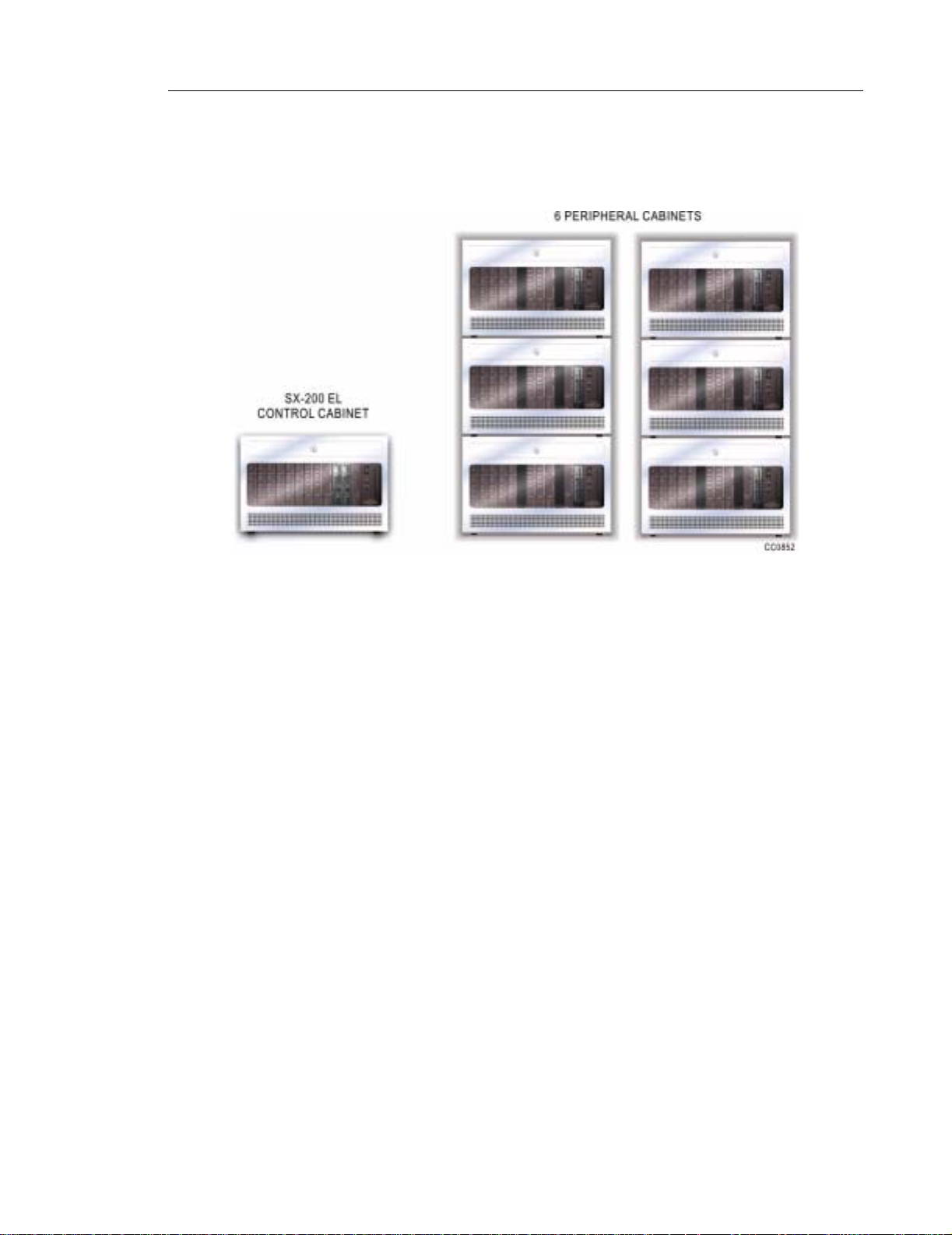
SX-200 EL System
The SX-200 EL system can support up to six peripheral bays, cabinets, or SX-200 IP Nodes.
Product Overview
The SX-200 EL System has the following characteristics:
• Main Control Card IIIEL (MCCIIIEL) or Main Control Card IIIELx (MCCIIIELx)
• Bay Control Card II or Bay Control Card III, Bay Power Supply Card, and depending on
the configuration, a maximum of two of the following carrier cards: Control Triple FIM
Carrier Card, Control Dual FIM Carrier Card, Control Triple CIM Card
• ONS/CLASS Line card, LS/GS card, LS/CLASS Trunk card, Universal card, COV card,
DID card, OPS card, DNIC card, PRI card, BRI card, Digital Lin e card , an d T1 car d
• Maximum of 96 physical ports using a single cabinet
• Maximum of six Peripheral cabinets, two SX-200 IP Nodes, six SPINE Bays, or six ISDN
Bays
• Maximum of 672 physical ports in the system
• Requires LIGHTWARE 17 or greater software. To support the SX-200 IP Node , you must
have LIGHTWARE 19 Release 3.0 or greater software.
50003510 Revision A 5
Page 20
SX-200 General Information Guide
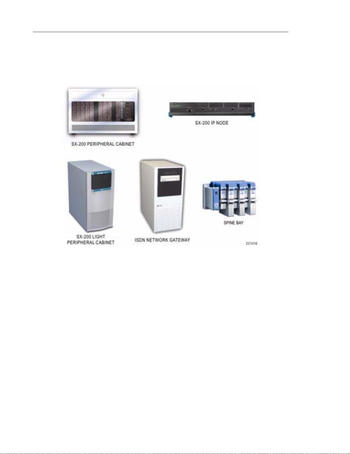
The six peripheral bays can be SX-200 peripheral cabin ets, SX-200 LIGHT peripheral cabinets,
SX-200 IP Nodes (requires the MCC IIIELx), SPINE bays, or ISDN bays (A SPINE bay
configured as bay 7 requires the MCC IIIELx). The ISDN bay may be an ISDN Network Gateway
or a PRI card.The PRI card fits into a main control cabinet or a peripheral cabinet.
6 Revision A 50003510
Page 21
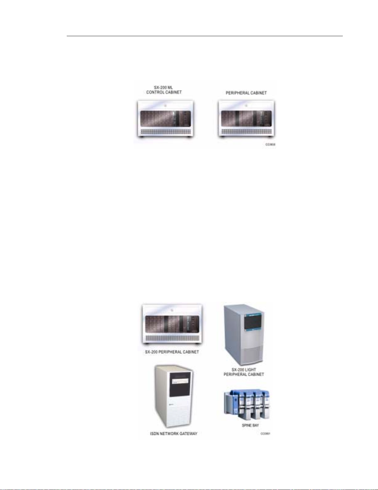
SX-200 ML System
The SX-200 ML system can support up to one peripheral bay or cabinet.
The SX-200 ML System has the following characteristics:
• Main Control Card IIIML (MCCIIIML)
• Bay Control Card II or Bay Control Card III, Bay Power Supply Card, and a Control Dual
FIM Carrier Card or a Control Triple CIM Card ( if expanding beyond the single cabinet)
• ONS/CLASS Line card, LS/GS card, LS/CLASS Trunk card, Universal card, COV card,
DID card, OPS card, DNIC card, PRI card, BRI card, and T1 card
Product Overview
• Maximum of 96 physical ports using a single cabinet
• Maximum of one peripheral cabinet, SPINE bay or ISDN bay
• Maximum of 192 physical ports with a peripheral bay
• Requires LIGHTWARE 17 or greater software
The one peripheral bay can be a SX-200 peripheral cab inet, SX-200 LIGHT peripheral cabinet,
SPINE bay, or ISDN bay. The ISDN bay may be an ISDN Network Gateway or a PRI card.The
PRI card fits into a main control cabinet.
50003510 Revision A 7
Page 22
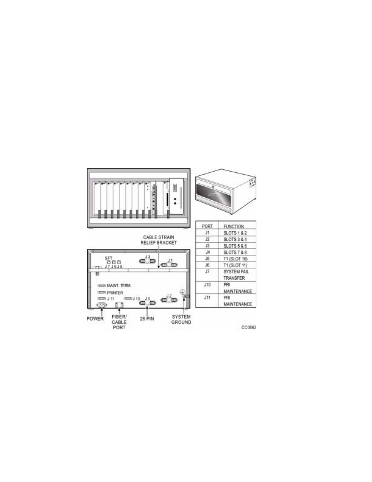
SX-200 General Information Guide
SX-200 ELx Cabinet
The SX-200 EL and the SX-200 ML system use the same rack mount (RM) horizontal cabi net,
the SX-200 ELx cabinet (PN 9109-600-002-NA), for the cont rol cabinet a nd for the peripher al
cabinet.
The horizontal cabinet can be mounted in a standard 19" rack, or they can be stacked. The
cabinet is plastic and plexiglass. The door on the cabinet allows the system administrator to
see the system status at a glance. The control cabinet and the peripheral bays are linked by
fibre or copper cables.
Located on the rear of the SX-200 ELx cabinet are four 25 pin connectors (J1- J4 for the
peripheral interface cards), three RJ-45 connecto rs (J5 and J6 for T1 trunks and J7 for a system
fail transfer control port), a printer port, a grounding connector, a maintenance port, and two
RS-232 connectors (J10 and J11 for the PRI maintenance).
The SX-200 ELx cabinet supports 12 card slots: eight slots support line and trunk cards, and
four support the control cards and the FIM or CIM carrier cards. The cabinet can be configured
as the control cabinet or as a peripheral cabinet. The SX-200 EL system using a MCCIIIELx
card requires the SX-200 ELx cabinet in order to accommodate the thre e links to each cabinet.
The system requires an SX-200 ELx cabinet to support any of the following cards or functionality:
• BCC III card
•PRI card
•BRI card
• CLASS functionality of the ONS/CLASS Line card
• SX-200 IP Node
8 Revision A 50003510
Page 23
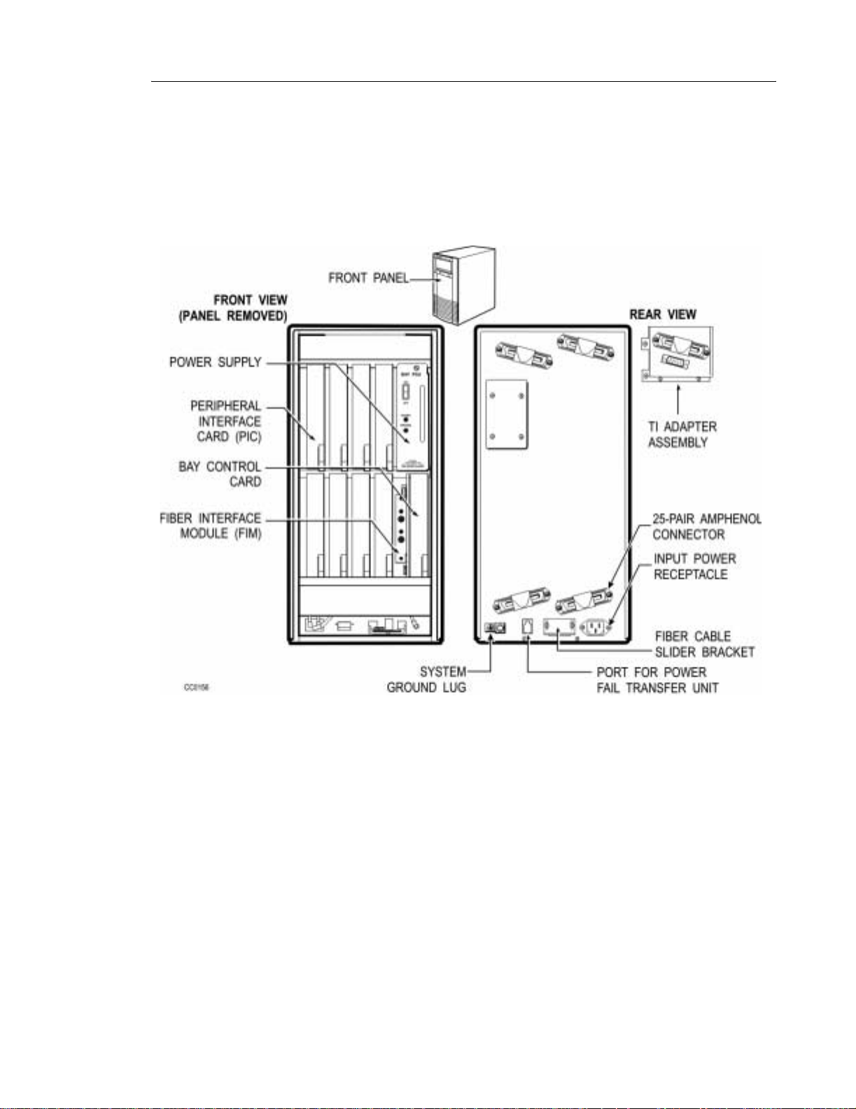
SX-200 LIGHT Peripheral Cabinet
The SX-200 LIGHT Peripheral Cabinet is vertical as opposed to horizontal. The cabinet contains
one Bay Power Supply, one Bay Control Card (with attached Peripheral FIM Carrier plus FIM),
and up to eight peripheral interface cards. The SX-200 LIGHT Peripheral Cabinet is shown
below.
Product Overview
50003510 Revision A 9
Page 24
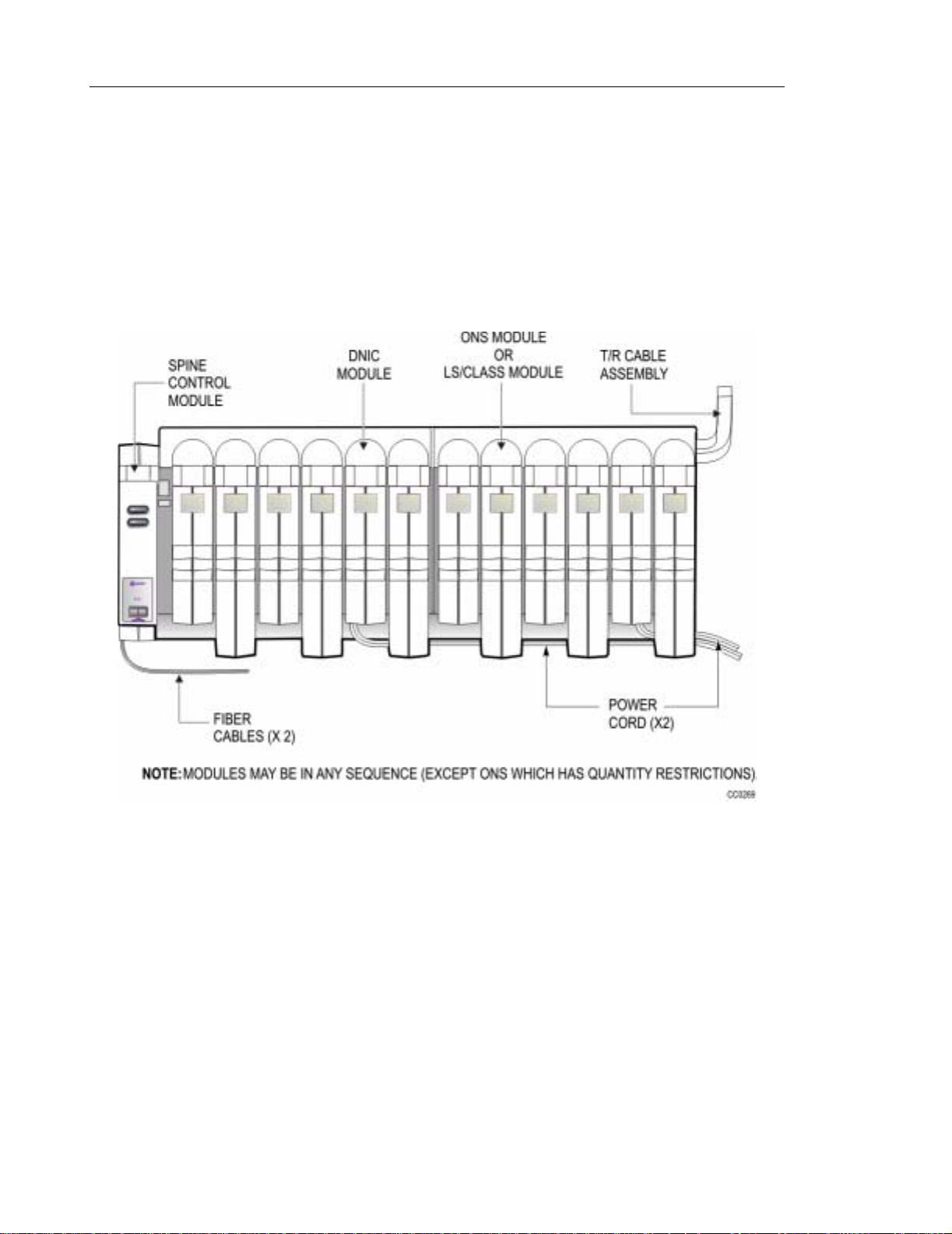
SX-200 General Information Guide
SX-200 SPINE Peripheral Bay
The SX-200 SPINE Peripheral Bay is available as a sing le (6 slot) or dual (12 slot) configuration.
Each SPINE Peripheral Bay contains one Power Module, and up to six peripheral modules.
The first SPINE Peripheral Bay (SPINE A) also contains a Control Module II (with FIM).
There are limitations regarding the ONS modules. If there ar e three ONS modules install ed in
SPINE A, no other modules may be installed on that SPINE.
The SPINE Peripheral Bay can be located up to 1 km from the control node.
10 Revision A 50003510
Page 25

SX-200 IP Node
The SX-200 IP Node brings Voice over IP (VoIP) capabilities to the SX-200 EL. The SX-200
IP Node addresses the LAN-based telephony requirements of small to medium enterprises and
corporate enterprises with branch offices and teleworkers. You can connect up to two SX- 200
IP Nodes to an SX-200 EL system.
The SX-200 EL system supports up to 120 IP devices. You can connect up to 60 IP devices
to each SX-200 IP Node and up to two SX-200 IP Nodes per SX-200 EL system. Each SX-200
IP Node supports up to 30 active IP phone-to-IP phone calls using voice compression.Up to
60 active calls can be made from IP phones to other devices, such as DNIC phones. Each
SX-200 IP Node also supports up to 30 IP trunks, which means an SX-200 EL system can
support up to 60 IP trunks.
The SX-200 IP Node offers
• Reduced telecommunication costs and related support costs
• The flexibility of LAN-based telephony combined with the feature-rich, reliable and proven
performance of the SX-200 EL
• Easy integration with existing circuit-switched telephony network and IP devices
Product Overview
• Fast installation of IP components in an existing SX-200 EL system
• The same easy-to-use functionality delivered by Mitel Networks DNIC phones
• An easy path for migrating your business communications to LAN-based telephony.
Your business can now gain these benefits and many others offered by the ro bust performance
of an Internet-enabled SX-200 EL.
50003510 Revision A 11
Page 26
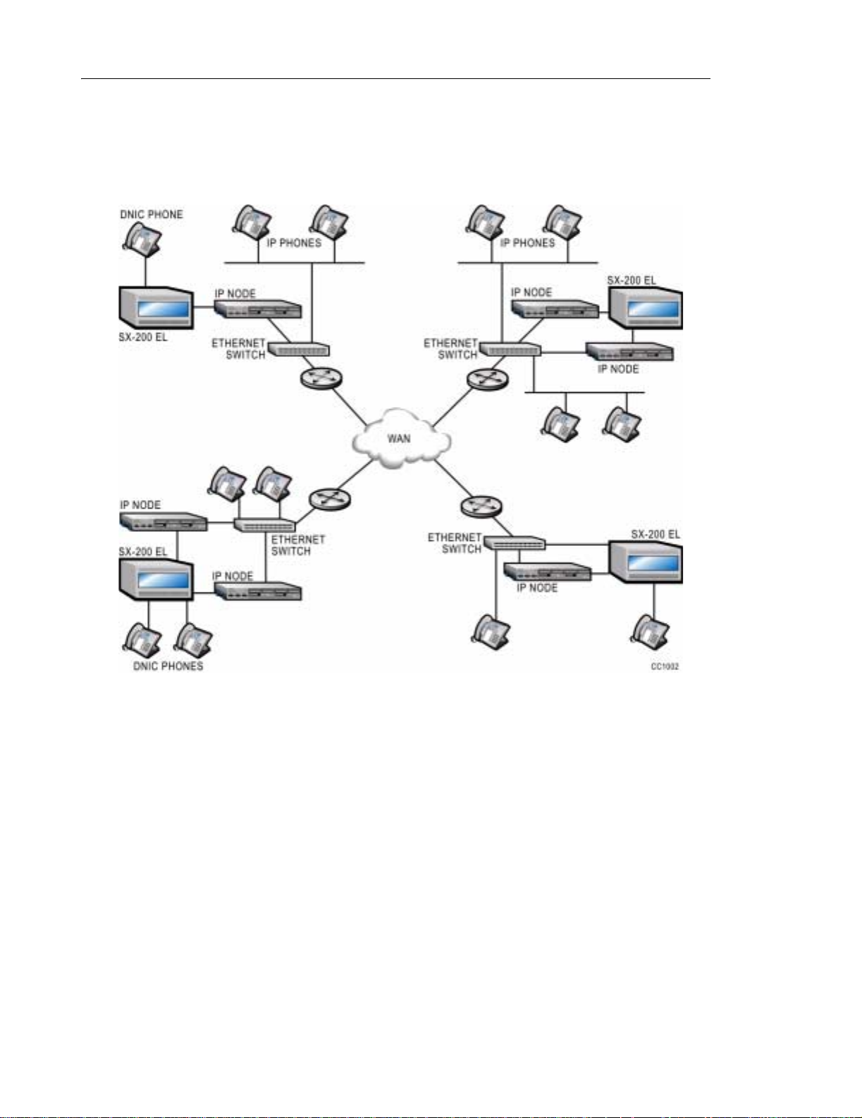
SX-200 General Information Guide
The SX-200 IP Node requires the following SX-200 system hardware:
• An SX-200 ELx Controller
• One or two Control Triple CIM Cards
12 Revision A 50003510
Page 27
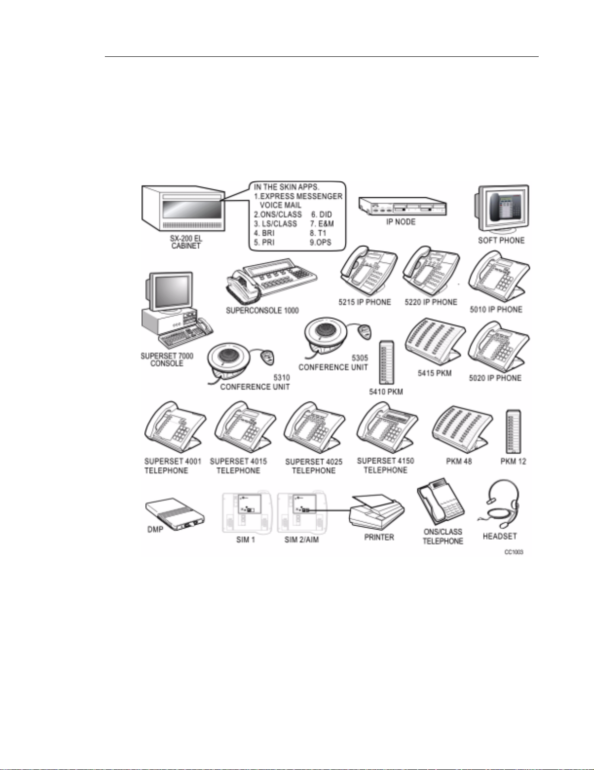
SX-200 EL/ML Peripheral Devices
The SX-200 EL and the SX-200 ML offer a wide range of peripheral devices to meet the voice
and data switching needs of virtually all small to medium enterprises. The SX-200 EL no w offers
Voice over IP functionality and adds new IP phones and conference units to its long list of
supported peripherals. Both the SX-200 ML and the SX-200 EL continue to support the highly
successful SUPERSET line of telephones.
Product Overview
50003510 Revision A 13
Page 28

SX-200 General Information Guide
Voice Capabilities
The SX-200 EL interfaces to analog, digital, and IP peripheral devices. The SX-200 ML system
interfaces to analog and digital peripheral devices. Peripheral devices fo r voice communications
include, but are not limited to, the following sets.
IP Peripherals (SX-200 EL only):
Mitel Networks 5201 IP Phone: The Mitel Networks 5201 IP Phone is a low-cost, single por t
entry-level IP telephone that connects to a 10BaseT Ethernet network. Features of the newly
designed telephone include:
• Three fixed-function keys: Hold, Message, and Transfer/Conference
• Handset and Ringer volume Control
• Message Waiting Lamp
• Wall-mounting
Mitel Networks 5010 IP Phone: The Mitel Networks 5010 IP phone is a multi-line IP telephone.
In addition to its 10 fixed function keys, the 5010 IP phone has six keys that you can program
as Speed Call keys, Featur e Access keys, or Line Appearances. The set also has a Message
key and a Microphone key, both with indicator lamps. On incoming calls, the message lamp
flashes in cadence with ringing of the set.
Mitel Networks 5020 IP Phone: The Mitel Networks 5020 IP phone is a multi-line IP telephone.
It has 14 programmable keys with associated LCD indicators. These keys can be progra mmed
as Speed Call keys, Feature Ac cess keys, or Line Appearances. One key must be reserved
for the prime line. Above the 14 programmable keys are a 2x20 alphanumeric bitmap graphics
display and three softkeys. The display comes with or without backlighting. The three softkeys
allow set users to select command prompts that appear in the display. The set also has a
Message key and a Microphone key, both with ind icator lamps, and eight fixed function keys
without indicator lamps. On incoming calls, the message lamp flashes in cadence with ringing
of the set.The 5020 IP phone offers half-duplex functionality with the speaker phone.
Mitel Networks 5215 IP Phone: The Mitel Networks 5215 IP phone is a multi-line IP phone.
In addition to its 10 fixed function keys, the 5215 IP phone ha s six keys that can be programmed
as Speed Call keys, Feature Access keys, or Line Appea rances. The set also has a Message
key and a Microphone key, both with indicator lamps. On incoming calls, the message lamp
flashes in cadence with ringing of the set.
Mitel Networks 5220 IP Phone: The Mitel Networks 5220 IP phone is a multi-line IP phone.
It has 14 programmable keys with associated LCD indicators. These keys can be progra mmed
as Speed Call keys, Feature Access keys, or Line Appearances. One key must be reserved
for the prime line. The three softkeys allow set users to select command promp ts that appear
in the display. The set also has a Message key and a Microphone key, both with indicator
lamps, and eight fixed function keys without indicator lamps. On incoming calls, the message
lamp flashes in cadence with ringing of the set. The 5220 IP phone offers half-duplex
functionality with the speaker phone.
14 Revision A 50003510
Page 29

Product Overview
Mitel Networks 5305 IP Office Conference Unit: The Mitel Networks 5305 IP Office
Conference Unit is a high-quality conference unit that uses acoustic beam-forming technology
to ensure superior performance. The unit is used with the 5020 IP Phone and connects to the
phone’s headset port. This unit is designed for optimal performance in a private office that
measures 12 feet by 15 feet (3.6 meters by 4.5 meters). The 5305 IP Conference Unit package
includes a speaker unit and a side control unit. An optional mouse controller is available.
Mitel Networks 5310 IP Board Room Conference Unit: The Mitel Networks 5310 IP Board
Room Conference Unit is a high-quality conference unit that uses acoustic beam-forming
technology to ensure superior performance. The unit is used with the 5020 IP Phone and
connects to the phone’s headset port. This unit is designed for o ptimal performance in a room
that measures 15 feet by 25 feet (4.5 meters by 7.6 meters). The 5310 IP Conference Unit
package includes a 5020 IP Phone, a speaker un it, and a side control unit. An optional mouse
controller is available.
Mitel Networks 5412 Programmable Key Module: The Mitel Networks 5412 Programmable
Key Module (PKM) provides 12 additional personal keys for a 5020 IP Phone. They can be
programmed as Feature keys, Speed Call keys, Direct Station Select keys, or as Line
Appearance keys. Each key has a Line Status Indicator that works the same way as those on
the associated phone.The 5412 PKM unit connects to a 5020 IP Phone by using a Mitel
Networks PKM Interface Module (IM). The PKM IM is installed separately at the base of phone
and is only compatible with 5020 IP Phones.
Mitel Networks 5448 Programmable Key Module: The Mitel Networks 5448 Programmable
Key Module provides 48 additional feature keys for a 5020 IP Phone. They can be programmed
as Feature keys, Speed Call keys, Direct Station Select keys, or as Line Appearance keys.
Each key has a Line Status Indicator that works the same way as those on the associated
phone. The keys can be programmed th ro ug h th e ph on e . Th e 54 4 8 PK M un it co nn ec ts to a
5020 IP Phone by using a Mitel Networks PKM IM. The PKM IM is installed separately at the
base of phone and is only compatible with 5020 IP Phones. A 5020 IP phone can support a
maximum of two 5448 PKMs, which together provide a total of 96 additional feature keys.
Mitel Networks 5410 Programmable Key Module: The Mitel Networks 5410 Programmable
Key Module (PKM) provides 12 additional personal keys for a 5020 IP Phone. They can be
programmed as Feature keys, Speed Call keys, Direct Station Select keys, or as Line
Appearance keys. Each key has a Line Status Indicator that works the same way as those on
the associated phone.The 5410 PKM unit connects to a 5020 IP Phone by using a Mitel
Networks PKM Interface Module (IM). The PKM IM is installed separately at the base of phone
and is only compatible with 5020 IP Phones.
Mitel Networks 5415 Programmable Key Module: The Mitel Networks 5415 Programmable
Key Module provides 48 additional feature keys for a 5020 IP Phone. They can be programmed
as Feature keys, Speed Call keys, Direct Station Select keys, or as Line Appearance keys.
Each key has a Line Status Indicator that works the same way as those on the associated
phone. The keys can be programmed th ro ug h th e ph on e . Th e 54 1 5 PK M un it co nn ec ts to a
5020 IP Phone by using a Mitel Networks PKM IM. The PKM IM is installed separately at the
base of phone and is only compatible with 5020 IP Phones. A 5020 IP phone can support a
maximum of two 5415 PKMs, which together provide a total of 96 additional feature keys.
50003510 Revision A 15
Page 30

SX-200 General Information Guide
Standard Telephones:
Industry-standard rotary dial and DTMF telepho nes are supported; ONS and OPS lines provide
an interface to the bay for these sets. The rotary telephone is not supported on the SX-200
SPINE.
SUPERSET 4001 Telephone: The SUPERSET 4001 telephone is a single-line digital
telephone. It has a Flash key, a Message key, a Hold/Retrieve key, seven Speed Dial keys, a
hold lamp, and a message indicator lamp, as well as keys for adjusting the ringer and handset
receiver volume. On incoming calls, the message lamp flashes in cadence with ringing of the set.
SUPERSET 4015 Telephone: The SUPERSET 4015 telephone is a multi-line digital telephone.
In addition to its 10 fixed function keys, the SUPERSET 4015 has six keys that can be
programmed as Speed Call keys, Feature Access keys or Line Appearances. Th e set also has
a Message key and Microphone key with indicator lamps. On incoming calls, the message lam p
flashes in cadence with ringing of the set.
SUPERSET 4025 Telephone: The SUPERSET 4025 is a multi-line digital telephone. It has 14
programmable keys with associated LCD indicators. These keys can be programmed as Speed
Call keys, Feature Access keys or Line Appearances. One key must be reserved fo r the prime
line. Above the 14 programmable keys are a 2x20 alpha numeric bitmap g raphics disp lay and
three softkeys. The display comes with backlighting or without backlighting. The three softkeys
allow set users to select command prompts that appear in the display. The set also has a
Message key and Microphone key with indicator lamps, and eig ht fixed function keys without
indicator lamps. On incoming calls, the message lamp flashes in cadence with ringing of the
set.The SUPERSET 4125 offers half-duplex functionality with the speaker phone.
SUPERSET 4090 Telephone: The SUPERSET 4090 telephone is a digital cord less telephone
equipped with a backup battery charging system and an extra battery. A belt clip and a
wall-mounting adapter are also included. The SUPERSET 4090 cordless may be used with
another 4000 Series set. You can set up Call Forward on the desk phone to send calls to th e
SUPERSET 4090 when you are away from your desk. You can also use a line appearance key
on the SUPERSET 4090 to answer calls to the Prime Line on your desk phone.
SUPERSET 4125 Telephone: The SUPERSET 4125 telephone is similar to the SUPERSET
4025 telephone. The difference between the two is that the SUPERSET 4125 can be connected
to a PC. The SUPERSET 4125 has a built-in RS-232 serial p ort to accomodate the connection
to a PC serial port.
The SUPERSET 4125 telephone, like the SUPERSET 4025 telephone, has 14 programmable
keys with associated LCD indicators. These keys can be programmed as Speed Call keys,
Feature Access keys or Line Appearances. Above the 14 programmable keys are a backlit,
2x20 alphanumeric bitmap graphics display and three softkeys. The three softkeys allow set
users to select command prompts that appear in the display. The set also has a Message key
and Microphone key with indicator lamps, and eight fixed function keys without indicator lamps.
On incoming calls, the message lamp flashes in cadence with ringing of the set. Th e set also
has a headset jack that allows the user to have a headset and handset p lugged in at the same
time. The SUPERSET 4125 offers half-duplex functionality with the speaker phone.
16 Revision A 50003510
Page 31

Product Overview
SUPERSET 4150 Telephone: The SUPERSET 4150 telephone is a multi-line digital telephone
that provides advanced telephony features and connectivity to a computer. A built-in RS-232
serial port accomodates the connection to a PC serial port. The SUPERSET 4150 has 14 keys
that can be programmed as Speed Call keys or Line Appearances. One key must be reserved
for the prime line. A backlit, alphanumeric display with six touch-sensitive softkey areas allows
users to select call handling features easily. On incoming calls, the message lamp flashes in
cadence with ringing of the set. The SUPERSET 4150 also offers full-duplex speaker
functionality when the power adapter is connected to the set.
Note: The SUPERSET 400 series telephones have been discontinued, however they
are still supported by the SX-200 system.
Attendant Console: The system supports three types of Attendant consoles; the LCD Console,
the SUPERCONSOLE 1000
®
Attendant Console, and the SUPERSET 7000 Attendant
Console. The LCD Console interfaces to a console module on the Universal Card, while the
SUPERCONSOLE 1000 and SUPERSET 7000 Attendant consoles interface by one pair wiring
to a DNIC circuit on a Digital Line Card.
Programmable Key Modules: Two types of Programmable Key Modules are available: the
Mitel Networks Programmable Key Module 12 PKM 12) and the Mitel Networks Pr ogrammable
Key Module 48 (PKM 48). The PKM 12 provides 12 add itional keys and line status displ ays to
SUPERSET 4025, SUPERSET 4125, or SUPERSET 4150 telephones. Only one PKM 12 can
be attached to the telephone. The PKM 48 provides 48 additional keys and line status displays
to an attendant console or to SUPERSET 4025, SUPERSET 4125, or SUPERSET 4150
telephones. Up to two PKM 48 devices may be attached to the telephone or to an attendant
console. Flash rates for the indicators are the same as on its associated telephone.
Notes:
1. The SUPERSET PKM has been discontinued but is still supported on the SX-200
system. This PKM provided 30 additional keys and line status displays to a
SUPERSET 410, SUPERSET 420, or SUPERSET 430 telephone. Up to three
PKMs could be attached to a telephone.
2. The SUPERSET DSS Module has also been discontinued but is still supported. This
module provided a 32-position Busy Lamp Fie ld an d a 32 -k ey dir ec t s ta tion sele ct
keypad for the associated SUPERSET telephone.
Interface Modules: Two types of interface modules are available. SUPERSET Interface
Module 1 (SIM1) interfaces a PKM 12 or up to two PKM 48 devices with a SUPERSET 4025,
SUPERSET 4125, or SUPERSET 4150 telephone. SUPERSET Interface Module 2 (SIM2)
interfaces a SUPERSET 4025, SUPERSET 4125, or SUPERSET 4150 telephone with a PKM
12 or up to two PKM 48 devices and an analog device, such as a telephone set, modem, or
FAX machine. Both interface modules are installed in the base of a SUPERSET 4025,
SUPERSET 4125, or SUPERSET 4150 telephone.
Direct Station Select/Busy Lamp Field (DSS/BLF) Interface Unit: This unit interfaces up to
two programmable key modules (PKM 48 devices) with an attendant console. Each PKM 48
provides the attendant console user with 48 DSS/BLF keys. Note that the SUPERCONSOLE
1000 with the back-lit display does not require this interface unit.
50003510 Revision A 17
Page 32

SX-200 General Information Guide
DNIC Music-on-Hold/Paging Unit: The DNIC Music-on-Hold/Paging Unit (DMP) can be
wall-mounted next to the PBX. It is powered by the system, and does not require a separate
power source. A single 25 pair amphenol connects to the PBX via the main distribution frame.
A single LED indicator provides basic status information. The DMP interfaces a standard DNIC
port to the following external equipment:
• External music source for Music-on-Hold
• External paging amplifier (with or without answerback capability)
• Up to two night bells
• An external alarm.
Voice Mail Products: The NuPoint Messenger™ voice processor works in conjunction with
your telephone to provide an effective and efficient communications tool. Wi th it, you can use
any multi-tone telephone to send and receive recorded messages at any time, a nywhere in the
world. In the office, NuPoint Messenger makes sure you don’t miss calls. Your telephone is
always answered with your personal message, even if you aren’t available. You have the option
of asking callers to leave a message, or giving them the name of someone else to contact.
The Mitel Networks 6500 Speech Enabled Applications is a PC based, speech recognition
application that allows SUPERSET 420, SUPERSET 430, SUPERSET 4025, SUPERSET
4125, and SUPERSET 4150 telephone users to plac e a call to a specific person or department
based on spoken commands or use speech to listen to and manage their messages,
appointments, meetings, and tasks within Microsoft Outlook.
The Mitel Express Messenger™ voice mail card allows an SX- 200 EL or the SX-200 ML system
to have a single card voice mail facility. This card allows a single voice mail card to provide
either two, four, six, or eight voice mail ports to an SX-200 EL or an SX-200 ML system that
has LIGHTWARE 16 Release 1.1 software or later. Softkey and Hospitality support is offered
with LIGHTWARE 17 Release 3.1 and greater and Mitel Express Messenger Version 2.1 an d
greater.
Release 4.11 of Mitel Express Messenger supports up to 300 mailboxes and provides 33 hours
of message file storage. After a call is forwarded to voice mail from an extension, the caller’s
calling line identification (CLID) and the forwarding extension number are passed to the Express
Messenger system. The Express Messenger offers
• Auto attendant
•Paging
• Record a Call
• Multiple Languages
• Secure personal mailboxes
• Broadcast message distribution
• Temporary greetings
• Unlimited message length
• Directory/name dialing
• Operating revert.
18 Revision A 50003510
Page 33

Product Overview
Data Capabilities
Datasets provide data facilities for terminals, digital SUPERSET telephones, and other types
of data circuits. The DATASET 1100 series support asynchronous data communications at
rates up to 19.2 kbps and interface with the system through a Digital Line Card or a DNIC
Module. The DATASET 2100 series support asynchronous and synchronous data
communications at rates up to 19.2 kbps and interface with the system through a Digital Line
Card or a DNIC Module.
MILINK Data Module: The MILINK Data Module is connected to a modular jack located on
the base of SUPERSET 410, SUPERSET 420, or SUPERSET 430 telephones, and i s used to
interface a terminal, personal computer, or other peripheral device to a host computer. The
MILINK Data Module interfaces to the system through the same pair of wires that the telephone
set voice circuit uses. The MILINK Data module is discontinued but is still supported with the
SX-200 system.
DATASET 1101 Cartridge: A DATASET 1101 Cartridge is mounted within a SUPERSET 3DN
or a SUPERSET 4DN telephone set. The cartridge is connected via an internal cable to the
telephone set circuit and is used to interface a terminal, personal computer, or other peripheral
device to a host computer. It interfaces to the system Digital Line Card through the same pair
of wires that the telephone set voice circuit uses.
DATASET 1103 Standalone: The DATASET 1103 Standalone is packaged in a flat case which
can be placed under a standard desk telephone set. The DATASET 1103 Cartridge usually
interfaces a terminal, a personal computer, a printer, a file disk, or another peripheral device
to the system, for connection to a host computer or to another peripheral device.
DATASET 2103 Standalone: The DATASET 2103 Standalone is a
Synchronous/Asynchronous data set which is used with Mitel Networks PBXs to interface
peripheral devices to the system. It is packaged in a flat case which can be placed under a
standard desk telephone set. The DATASET 2103 Standalone connects to a DNIC circuit within
the PBX by a single twisted pair (the telephone set is connected independently).
Terminals and Printers: A VT100™ compatible terminal or personal computer with VT100
terminal emulation software can be connected to the system as a maintenance terminal. Printers
are used to create hard-copy records such as traffic reports, maintenance information, etc.
50003510 Revision A 19
Page 34

SX-200 General Information Guide
20 Revision A 50003510
Page 35

Supporting Applications
In the SX-200 EL and the SX-200 ML system, groups of features have been combined into
applications designed to meet the specialized needs of small to medium size enterprises.
Applications can simplify call handling and control communication costs in business,
commercial and institutional environments, simplify hotel/motel ope ration, enhance any
telephone sales activity, and provide a cost-effective way for small organizations to access
advanced business features.
Voice over IP (VoIP)
With the introduction of the Mitel Networks SX-200 IP Node, the SX-200 EL now brings the
cost-saving benefits of Voice over IP (VoIP) to small to medium enterprises and corporate
enterprises with remote offices and teleworkers. The SX-200 IP Node supports up to 60 IP
phones per IP Node and up to 120 IP phones per SX-200 EL system. Each SX-200 IP Node
supports up to 30 IP phones with voice compression.
Business/Commercial/Institutional
The SX-200 EL and the SX-200 ML system business features, such as un iform call distribution
and verified account codes, enhance your communications capability. They offer your
organization flexible office configurations, control of your personnel’s telephone privileges,
control of communication costs, and traffic measurement reports.
On an individual basis, they offer your employees personalized call management capabilities
- campon, speed calling, messaging, conferencing, and callback to a line that is busy or doesn’t
answer.
Key system functionality is provided for those companies or divisions that are interested in
having a departmental key system application within their system environment.
Hotel/Motel
The Hotel/Motel application is a purchasable option.
Hotel/Motel features speed up guest check in and check out, and allow you to manage your
rooms efficiently, wake up guests on request, control guest telephone privileges, recover the
cost of guest calls (SMDR supported), and notify guests of their messages. These functions
are all handled by the Attendant or front desk clerk using the SUPERCONSOLE 1000 Attendant
Console or the Front Desk Terminal.
The Front Desk Terminal interfaces to the SX-200 EL and SX-200 ML systems through an
1100-Series DATASET. If efficient billing is in place the Front Desk Terminal provides a low-cost
alternative to a Property Management System (PMS) for smaller Hotel/Motel operato rs (in the
40 - 90 room size). It is ideal for fast check in and out, guest location, and house keeping
functions.
50003510 Revision A 21
Page 36

SX-200 General Information Guide
For computerized control and monitoring of Hotel/Motel functions, the system ca n interface to
a property management system (PMS).
Hotel/Motel and Front Desk Terminal function s ar e mutu a lly exclu siv e with Prop er ty
Management System (PMS).
Assisted Living
Mitel Networks 6451 Intelligent Dispatch is a PC software application that provides the ideal
alarm messaging system for Assisted Living Centers with less than 250 rooms. The messaging
system sends telephone, pull cord, and door alarms from extended care residents to
wired/wireless telephones or pagers of the nurses/caregiver.
The nurses/caregivers can
• Provide immediate care 24-hours a day
The management can
• Provide a discrete alarm system
• Provide alarm logs
• Ensure constant supervision
• Increase staff efficiency
Mitel Networks 6451 Intelligent Dispatch ensures a superior alarm system by using Guardian;
a safety net for the alarm messaging system. Guardian provides a constant watch and flags
any malfunctions in the system and in the devices being mo nit or ed.
Mitel Networks 6451 Intelligent Dispatch supports the following alarm types:
• Telephone Timer Alarm
The Telephone Timer alarm generates when the telepho ne of the resident is in the following
states:
- Off-hook and nothing dialed in a specified time period
- Off-hook, incomplete dialing, and idle for a specified time period
- On hold for a specified time period
- Abnormal states (re-order tone) for a specified time period.
The Telephone Timer alarm does not generate if the telephone is in a connected state or
if the telephone is on-hook.
• Emergency 911 Alarm
The Emergency 911 alarm generates when a resident or an attendant dials 911. This
alarm notifies staff of an emergency, so the appropriate actions can take place.
• Assistance Required Alarm (pull cords)
The Assistance Required alarm generates when a pull cord is pulled. This alarm will remain
active until the pull cord is put back to its normal state.
22 Revision A 50003510
Page 37

• Door Alarm
The Door alarm generates when a monitored door opens. The monitored doors have
two-wired contact sensors; one on the frame and one on the movable door. When the
door opens, the sensor contact is lost and the sensor generate s an alarm. The alarm goes
off when the door opens and remains active until the attendant takes responsibility for the
alarm and closes the door. If the door is opened and closed immediately, the alarm will
remain active until an attendant takes responsibility for the alarm.
Call Management
The SX-200 EL and the SX-200 ML systems are designed to meet the needs of customers with
special call management requirements. The system has the flexibility to accommodate users
needing a large number of account codes or abbreviated dialing numbers, as well as those
who wish to control communications costs by connecting to a private network or alternate
common carrier. Three of the major call management facilities are outlined below.
Dynamic Memory Allocation: For maximum flexibility, the SX-200 EL and the SX-200 ML
systems allocate memory only as required to features such as ARS, Toll Control, Verified
Account Codes, and Abbreviated Dialing. This avoids the problems associated with allocating
fixed blocks of memory to a particular feature.
Supporting Applications
Universal Digit Handling: Universal Digit Handling gives the SX-200 EL and SX-200 ML
systems flexibility in processing dialed digits. It can handle any string from one to 26 digits long.
This accommodates both North American and International numbering plans. It also allows
access to alternative common carriers.
Internal telephone numbers can be one to five digits long, and conflicts are allowed. For
example, extension 123 conflicts with extension 1234. The system can differentiate between
conflicting extension numbers. Conflic t s could slow down system performance.
Dial-in trunks can have up to two prefix digits to allow fo r setup of seven-digit priva te networks
and flexible handling of incoming calls.
Automatic Route Selection and Toll Control: Automatic Route Selection (ARS) and Toll
Control are integrated features. Long-distance checks are completed before the system selects
a trunk. Illegal calls are stopped as soon as they are recogn ize d, and allow ed calls, sele ct a
trunk group as soon as the route is known. To prevent long delays, dialing on the trunk can
start while you are dialing.
Universal Digit Handling, ARS and Toll Control can handle any dialed string from one to 26 digits.
ACD TELEMARKETER® Application
The ACD TELEMARKETER application is a purchasable option.
The ACD TELEMARKETER application is an advanced Automatic Call Distribution (ACD)
system that is fully integrated with the SX-200 EL/ML systems, and designed with the power
and performance needed to ensure satisfaction in the most demanding call center
50003510 Revision A 23
Page 38

SX-200 General Information Guide
environments. For maximum efficiency, all ACD personnel use SUPERSET 4015, SUPERSET
4025, SUPERSET 4125, SUPERSET 420, and SUPERSET 410 telephones programmed with
special displays and softkeys. With LIGHTW ARE 17 Release 3.0 and greater software, the
ACD personnel may also use the SUPERSET 4150 and SUPERSET 430. The displays provide
call status and progress messages; the softkeys give single button selection of ACD features.
The heart of the ACD TELEMARKETER feature is the ACD PATH, an innovative call routing
design that guides incoming calls through the system. See ACD Path, page 133. The ACD
TELEMARKETER feature also uses predictive overflow to keep call queueing time to a
minimum. See Predictive Overflow, page 134.
The ACD TELEMARKETER feature includes real-time displays via standard asynchronous
datasets and ASCII terminals. Thirteen displays encompass every area of the ACD operation.
The purchasable option, Maximum ACD Agents, enables the maximu m number of ACD agents
that can be logged in concurrently. This maximum number is from 0 throu gh 100, in increments
of 5.
Complementing the ACD TELEMARKETER application is a reporting system offered by Mitel
Networks 6100 Contact Center Solutions . The purchasable option, ACD Real Time Event,
enables the system together with Mitel Networks 6100 Contact Center Solutions on a host
computer, to monitor and record the activity of the ACD operation in real time.
Automated Attendant
The automated attendant application is a purchasable option.
Automated attendant features connect incoming calls from a DTMF telephone to a recording.
The recording instructs the caller to dial one or more digits to be routed to a specific answering
point, such as sales, service, parts, or general office. Once a digit is dialed, the system can
add prefix digits in front of the dialed digit to provide a valid extension number, a hunt group
number, a system abbreviated dial number, or a feature access code. If a digit is not dialed (o r
cannot be dialed because the incoming telephone is not DTMF) the incoming caller is routed
to a default answering point at the completion of the message.
The automated attendant feature supports the FAX tone detection feature. Both of these
features are optional and must be purchased.
MITEL MyAttendant
MITEL MyAttendant is a software applicat ion that provides a call answering position for a
multi-tenant environment or for a general business with multiple departments and mobile
workers. This PC application allows the user to work on other PC applications when there are
no incoming calls and when there are calls, allows the PC user to effectively manage calls for
multiple clients.
MITEL MyAttendant
• Provides a Message Board where messages are typed, saved , printed or emaile d to the
employee
24 Revision A 50003510
Page 39

Supporting Applications
• Allows the programming of customized greetings for different incoming trunks
• Lists employees associated with each incoming LDN to allow easy transferring
• Shows specific transfer information; e.g., cell phones, extensions, or pager numbers for
each employee
MITEL MyAttendant on a PC can be used in conjunction with other PCs with MITEL MyAttendant
to allow a group of attendants to work as a team. Information such as the client database, and
information about calls waiting in the queue is shared via a local area network.
The MITEL MyAttendant system consists of a system unit (PC), monitor, keyboard, TALK TO
CX card, a handset, and optionally a local area network.
The purchased package includes a MITEL MyAttendant Installation Disc, a TALK TO CX card,
a handset and cradle, and keyboard stickers. Documentation is provided on the MITEL
MyAttendant Installation Disc.
You can use a headset instead of the handset. The headsets that are qualified for use with
MITEL MyAttendant are the Monaural Overhead Headset PN 9132-800-500-NA and the
Binaural Overhead Headset PN 50000606.
MITEL MyAttendant requires LIGHTWARE 17 Release 4.0 or greater.
FAX Tone Detection
The FAX tone detection application is a purchasable option.
FAX Tone Detection allows incoming FAX calls arriving on the Automated Attendant trunks to
be automatically routed to a preprogrammed FAX ma chine . The Autom ated Atte ndant o ption
must be enabled before enabling the FAX Tone Detection option.
Centralized Attendant
®
The Centalized Attendant application is a purchasable option.
The Centralized Attendant feature allows an attendant on one system to answer calls that arrive
at another interconnected system. The call arrives at the attendant via a dedicated Release
Link Trunk (RLT), which can be T1 E&M, T1 E&M DISA, E&M, or E&M DISA. When the attendant
releases a call to its destination, the RLT is released.
Centralized Voice Mail
The Centalized Voice Mail application is a purchasable option
The Centralized Voice Mail feature allows a single voice mail device to service several
interconnected PBXs with LIGHTWARE 17 and greater software.
50003510 Revision A 25
Page 40

SX-200 General Information Guide
Tenanting
Economy of scale makes sharing system services practical. Using the tenanting features, up
to 25 small businesses, or departments of a larger business, can share the services of an
SX-200 EL or SX-200 ML system. Logically, the system can be divided into up to 25 separate
PBXs, each providing its tenant with customized features and services.
Consoles, night bells, Music-on-Hold, CO trun ks, and dial-in trunks can either be shared
between tenants or allocated individually to each tenant. Switching to night service can be done
centrally, or by an individual tenant. Calls through the system can be blocked, so tenants can
only call each other on CO trunks. Unanswered or after-hours calls can be answered by a
“landlord” console.
Tenants can gain additional flexibility by using SUPERSET display telephones as subattendant
positions. The main console position could be hand led by these telephones, using line buttons
to receive tenant recalls.
Data calls may be assigned to separate tenants, as required, to control access to data devices.
MITEL Application Interface (MAI) Package
The MITEL Application Interface (MAI) package is a purchasable option.
The MITEL Application Interface (MAI) software package allows MITEL computer-based
applications to access the system features. MAI is used in conjunction with an external host
computer connected via an RS-232 link to a DAT ASET 2100 device. T he DATASET device is
connected to a DNIC port on the system via a single twisted pair.
Data Switching
The family of datasets meets customers’ expand ing data-switching needs by integr ating voice
and data in the SX-200 EL or SX-200 ML systems. Datasets provide access to data switching
in ASCII format for all types of synchronous and asynchronous data devices.
Data switching is transparent to the system. When data is switched through the system its data
format and protocol are unchanged.
For switching data over longer distances, modems can be connected to the system. Mode ms
can be associated with Datasets in a modem pool hunt group for improved access to the system.
NuPoint Messenger
NuPoint Messenger voice mail is an optional service. This powerful PC-based voice processing
system, provides call processing, voice and fax messaging, as well as paging support.
With NuPoint Messenger, you can send and receive voice, fax, and compound voice and fax
messages at any hour of the day from any multi- tone telepho ne in the wo rld. You can call the
system and access your messages quickly and easily by following the prompts. Fax and voice
26 Revision A 50003510
Page 41

messages are sent and received from your personal “mailbox”. This give you access to
information remotely, and assures you of secure access to your documents. You determine
when and where you want your fax messages delivered.
The caller is given the choice of recording a message, speaking to someone else, or requesting
personal assistance. When someone has left a message for you, NuPoint Messenger can notify
you in a variety of ways:
• Message Delivery allows you to define a schedule so that if a message arrives in your
mailbox, NuPoint Messenger will call you at a specific telephone number at a specific time
so that you can retrieve the message
• Paging allows you to define a schedule so that when a message arrives in your mailbox,
NuPoint Messenger notifies your pager.
MiteI Express Messenger
Mitel Express Messenger is an automated voice mail system for handling telephone calls and
taking messages; it is designed specifically for operation with your telephone. Express
messenger provides you with a mailbox for sending and receiving messages, which you can
personalize with your name, a greeting, and a private passcode.
Supporting Applications
Mitel Express Messenger provides notification of messages to pagers or other telephones and
includes an Automated Attendant which is able to detect and forward incoming FAX calls.
Mitel Express Messenger provides up to eight voice mail ports to a SX-200 ML or SX- 200 EL
system that has LIGHTWARE 16 Release 1.1 or later software. More than one Express
Messenger may be installed in a system; however, each Express Messenger will operate
independently. For example, multiple Express Messenger systems co uld be installed to provide
voice mail support to several tenants. Express Messenger typically supports 10 to 25 users per
port, depending on the usage of Express Messenger.
MITEL TAPI Desktop Software
The MITEL TAPI (Telephony Application Programming Interface) Desktop software provides
communication between the PC and the telephone. The users can activate management
functions on first-party calls (e.g. dial, answer, hold, forward) from their PC.
The MITEL TAPI Desktop software enables the communication between the SX-200 system
and the PC via an RS-232 cable on a SUPERSET 4150 or SUPERSET 4125 telephone. The
SUPERSET 4150 and the SUPERSET 4125 telephone are sold packaged with the MITEL TAPI
Desktop software on a CD, an AC power adapter, and an RS-232 cable.
A MOSS password enables the feature,TAPI Support Over DNIC. This purchasable system
option enables a maximum number of TAPI desktops. The option is sold in increments of 5
TAPI desktops and the maximum number available is 50 per system. Recommended
configurations suggest a maximum of 24 sets per bay and a maximum of 3 sets per DNIC card.
50003510 Revision A 27
Page 42

SX-200 General Information Guide
Mitel Networks 6100 Contact Center Solutions
Mitel Networks 6100 Contact Center Solutions (6100 CCS) include automated call distribution,
interactive voice response, computer-telephony integration , real-time workforce management,
intelligent in-queue messaging, email, web chat, fax routing an d queuing, and comprehensive
reporting capabilities. The 6100 CCS product has a suite of applications that enable customers
to maximize the efficiency of their call center.
The 6100 CCS product incorporates
• Mitel Networks 6110 Contact Center Management
• Mitel Networks 6115 Interactive Contact Center
• Mitel Networks 6120 Contact Center Scheduling
• Mitel Networks 6150 Multimedia Contact Center
• Mitel Networks 6160 Intelligent Queue.
Mitel Networks 6110 Contact Center Management is an application that manages ACD
information. The application uses a familiar Microsoft Excel and Microsoft Internet Explorer
interface. Call Center managers can log on to any PC to run reports, monito r real time activities,
forecast the number of agents required, and perform numerous management functions over
the network.
Mitel Networks 6115 Interactive Contact Center enables supervisors to alter the way calls are
handled in the call center.
Mitel Networks 6120 Contact Center Scheduling works in conjunction with the Mitel Networks
6110 Contact Center Management application to optimize staffing levels to match business
needs.
Mitel Networks 6150 Multimedia Contact Center works with Microsoft Exchange and Outlook
to provide Contact Centers with automatic e-mail distribution. E-mails are sent to one address,
and the application manages the distribution based on agent availability and skill level. The
process is similar to the way that Automatic Call Distribution works for telephone calls.
Mitel Networks 6160 Intelligent Queue enhances Mitel Networks 6110 Contact Center
Management. 6160 IQ is an intelligent recorded announcement device (RAD) that allows call
centers to customize which messages callers will hear based on the time, date, and/or number
of callers in the queue. The application is managed through a we b-based interface with .WAV
file recordings.
28 Revision A 50003510
Page 43

Mitel Networks 6500 Speech-Enabled Applications
Mitel Networks 6500 Speech-Enabled Applications is a PC based, speech recognition
application that routes incoming calls to a specific person or department based on spoken
commands. Typically, you state the name of the person that you want to speak to and the
system routes your call to the requested pa rt y.
The 6500 SE Applications have two systems: 6500 SE Attendant and the 6500 SE Unified
Messaging.
The 6500 SE Attendant system has the following key features:
• Users can place a call to any number in the corporate directory by stating a name, extension, or department
• Internal users who have the required system privileges can call into the system from an
external number and place a call to any numbe r that is in the corporate d irectory by using
speech
• Registered users can program their own directory list of frequently called numbers and
then place calls to those numbers by using speech.
Supporting Applications
The 6500 SE Unified Messaging system has the following key features:
• Provides all the functionality of the 6500 SE Attendant plus allows users to access their
email and voice mail messages in their inbox of Microsoft Outlook through spoken commands. Users can address messages by name and use voice commands to search or
sort messages by sender or message type.
• With the Fax Integration software, users can use their telephone to identify incoming faxes
in their inbox of Microsoft Outlook and forward the fax messag e to a fax machine of their
choice.
• With the Calendar and Task Management software, users can use their telephone to
manage their appointments, tasks, and meeting requests in Microsoft Outlook.
The 6500 SE Applications interface to the system via a number of DNIC ports.The auto
attendant is available in two- to 24- port configurations in 2-port increments.
50003510 Revision A 29
Page 44

SX-200 General Information Guide
ISDN Support
The Integrated Services Digital Network (ISDN), transmitting voice, data and video at high
speeds, accurately and without a modem, has revolutionised communications. ISDN services
can be deployed and accessed at ente r pr ise, department and desktop levels by its simple
addition to your existing SX-200 network. ISDN proves its worth by its ability to carry voice,
data and video imaging on one network.
ISDN standards define two types of ISDN interface. Basic rate interface (BRI) is defined as
2B+D: two 64 kbs B channels and one 16 kbs D channel. T1 ISDN Primary rate interface (PRI)
is defined as 23B+D: 23 64 kbs B channels and one 16 kbs D channel. The B channels carry
voice or data, and the D channel provides the signaling channel.
Basic Rate Interface Card
BRI is typically used for video conferencing and providing access to inexpensive digital trunking
for small sites. BRI software supports National ISDN 1 (NI-1) and NI-2 basic call and incoming
calling name delivery. On the trunk side, BRI software supports an access point for video
conferencing and Group 4 fax. It also supports internet access for PC data terminals, and it
can provide a voice alternative to analog lines for small systems. On the line side, BRI software
supports the requirements for hosting a videoconference unit, a Group 4 fax unit, or a PC with
a BRI interface. One common line-side BRI application is hosting an Xpress Office Teleworker
(5232i) for remote DNIC operation either directly, or through a PRI channel.
30 Revision A 50003510
Page 45

Supporting Applications
The BRI card supports the following ISDN Services:
• Calling Party Number (CPN) - This number substitutes the calling station number on
outgoing calls for purposes of network identification and call back.
• Calling Name ID (CNID) - This ID is the incoming call name delivery per NA DMS100
custom specification.This Calling Name feature is an option that must be enabled at the
Central Office. The SX-200 only supports the inbound calling name.
• Calling Line Identification Presentation (CLIP) - The Calling Party Number can be
provided to the ISDN Network for outgoing calls or provided to the BRI card from the ISDN
Network for incoming calls. This information is passed onto the system and can be used
for database applications such as screen pops and for inclusion in SMDR records.
• Calling Line Identification Restriction (CLIR) - This feature allows users to prevent their
telephone number from being presented to the called party.
ISDN Primary Rate Interface Card
ISDN Primary Rate Interface (PRI) is becoming the most cost-effective solution for accessing
enhanced voice capabilities. All inbound and outbound services that are usually obtained by
using different trunk types (such as INWATS, OUTWATS, FX, Tie, and DID) can be accessed
with a single ISDN trunk; as a result, the number of system trunks can be reduced by 10 to 15
percent. On outbound calls, the system requests the required service from the Network. The
trunk takes on the requested characteristics for the duration of the call.
The PRI card provides two ISDN links and provides the same functionality as the two link ISDN
Network Gateway. The PRI card has the Bearer Capabilities (BC) of Speech (voice) and 3.1
kHz audio. The card also transports the BCs of rate-adapted 56 kbs data and unrestricted 64
kbs data transparently through the system.
The PRI card supports the following ISDN network services:
• Calling Party Number (CPN) - This number substitutes the calling station number on
outgoing calls for purposes of network identification and call back.
• Calling Name ID (CNID) - This ID is the incoming calling name delivery per NA DMS100
custom specification or National ISDN-3 (NI3).
• Calling Line Identification Presentation (CLIP) - The Calling Party Number can be
provided to the ISDN Network for outgoing calls or provided to the PRI card from the ISDN
Network for incoming calls. This information is passed onto the system and can be used
for database applications such as screen pops and for inclusion in SMDR records.
• Calling Line Identification Restriction (CLIR) - This feature allows users to prevent their
telephone number from being presented to the called party.
• Partial PRI Links - The SX-200 PRI card will support COs that provide this feature.
• Direct Dial-In (DDI) - DDI is an ISDN option that allows direct access to a line behind a
system through a unique directory number. This allows the dialed digits of an incoming
ISDN call to be presented to the system. All ISDN trunks are treated as Dial-In trunks; the
CO always sends digits to the system.
50003510 Revision A 31
Page 46

SX-200 General Information Guide
• Call-By-Call Service Selection (CBC) - This feature allows telephone users to select th e
ISDN network services that they wish to use on a per call basis.
• DID Calling Party Number Forwarding - Outgoing CPN delivers the calling party’s DID
number to the Network when the call has been identified as a call from a device with an
associated DID number instead of delivering the main directory number associated with
the system.
• Equal Access to Interexchange Carriers - The system provides a carrier access code
to the ISDN Network Gateway which identifies to the Central Office which Interexchange
Carrier is to receive the call. The system outpulses a digit string which includes a carrier
access code, followed by an identification number, followed by the called number.
• Min/Max - This feature allows a customer to control incoming and outgoing call traffic.
Minimums are assigned to ensure that a part icular type of call (such as INWATS) always
has a set number of lines available. Maximums are assigned to limit certain types of calls,
i.e., OUTWATS. This ensures that resources are not used up by a single type of call.
Different Min/Max databases can be created for different times of the day or for special
occasions such as telethons or infomercials.
• Auto Min/Max - This feature provides user programmable time-of-day au tomatic control
of Min/Max parameters.
• NFAS (Non-Facility Associated signaling) - NFAS allows you to use a single D-channel
to handle the signaling requirements for a group of PRI links that all use the same Protocol.
This feature eliminates the need to purcha se a D-channel for each link. NFAS is mainly
for North America.
• D-Channel Backup - This feature is used for signaling to establish and maintain the
circuit, and to send user data. D-channel Backup provides an alter nate D-channel for calls
related to NFAS. If the active D-channel fails, the system switches to the backup D-channel
to support call processing. This functionality is mainly for North America. NFAS is required
in order to program D-channel Backup.
• Q.SIG - This feature provides the ability to connect Q.SIG compatible PBXs from different
vendors together to form a private network and to connect the SX-200 to the SX-2000
LIGHT system or any other Q.SIG compatible PBX. Q.SIG features that are supported
include Calling Name for incoming calls, Message Waiting Indication, Call Transfer, Call
Diversion, and Path Replacement.
• Remote LAN Access - This feature provides LAN access to the wide area network (WAN)
for both incoming and outgoing calls through LAN servers (routers or bridges).
• Multiple Variants and Configurations - This feature provides the ability to run multiple
protocol variants and program multiple configurations on the two links of the PRI Gateway
through the IMAT application. The option to run multiple variants allows you to connect
the PRI Gateway to two different CO switches. The option to run multiple configurations
allows you to program Network-side on one link of the PRI Gateway a nd program User-side
on the other link of the PRI Gateway. For more information on programming multiple
variants and configurations, refer to the IMAT online Help.
32 Revision A 50003510
Page 47

ISDN Network Gateway (North America only)
The ISDN Network Gateway delivers the full benefits of ISDN network services for PRI voice
applications. ISDN delivers the highest degree of voice clarity of any transmission medium
available.
The ISDN Network Gateway lets you take full advantage of these enhanced voice capabilities
including calling number identification services (CLID/ANI) and called-line identification
(DDI/DNIS), which allow you to know who’s calling and facilitate call center and CTI applications.
Plus, the ISDN Network Gateway supports fast call set-up, call-by-call, and Min/Ma x to speed
call handling and make more efficient use of trunking.
SX-200 MyAdministrator
The SX-200 MyAdministrator software application allows the user to perform basic changes to
the telephone configuration. With this application, the user co nnects to the system site l ocally
or remotely and can add, modify, or delete telephone sets; add, modify, or delete telephone
features, and control membership in telephone groups.
This application can manage the following device types:
Supporting Applications
• Mitel Networks 5010, 5020, 5215, and 5220 IP Phones
• Mitel Networks 5305 and 5310 IP Board Room Conference Units
• ONS Stations
• SUPERSET 401 and SUPERSET 4001 (key programming is not supported)
• SUPERSET 410, SUPERSET 4105, SUPERSET 420, SUPERSET 4025, SUPERSET
4125, and SUPERSET 4090
• SUPERSET 430, SUPERSET 4150, and their sub-attendant variants
• Programmable Key Modules
The application identifies the following devices: PKM Interface Unit (DSS/BLF Interface Unit),
COV, SUPERSET 3DN telephones, SUPERSET 4DN telephones, and DMP Units. You can
not program these devices.
The application works on a Pentium™ computer that has a minimum of 32 MB RAM, a CD-ROM
Drive, keyboard and mouse. The application is designed for use with the Microsoft
98, Windows 95, Windows 2000 Professional, Windows Millennium Edition, or a Windows NT
4.0 Workstation (Service Pack 4.0 or greater) operating system.
The PBX requirements consist of SX-200 LIGHTWARE 19 Release 1.0 or greater software
and the purchasable System Option 80, MyAdministrator Access. The PC is connected to the
PBX via the Maintenance Terminal at the back of the SX-200 cabinet. The PC is connected
directly with an RS-232 cable or indirectly with two modems, a null modem adapter, and two
RS-232 cables. The null modem adapter goes on the PBX side.
®
Windows™
50003510 Revision A 33
Page 48

SX-200 General Information Guide
System Fail Transfer
System Fail Transfer (SFT) (or power fail transfer) is provided by the SFT control port, allowin g
preselected DTMF or rotary telephones to be connected directly to CO trunks in the event of
system failure in the system. To provide system fail transfer, an external SFT unit or SPINE
Bay LS/CLASS trunks are required.
34 Revision A 50003510
Page 49

Configuration
By designing your SX-200 EL and SX-200 ML systems for maximum flexibility, Mitel Networks
gives you the capability of customizing your system to meet your requirements. Select the
system configuration and options you need today with the assurance th at you can expand the
system at any time in the future.
Reliability is a key factor in the choice of any communications system. Mitel Networks has
ensured the continued reliability of the SX-200 EL and SX-200 ML system by designing to wide
tolerances and using proven components.
Usability is enhanced by the elegant simplicity of the hardware design - streamlined control
architecture, specialized peripheral cards, and flash card-based software.
The SX-200 EL system is a microprocessor-controlled te lep h on e sys tem th at swit ch es bo th
voice and data for installation up to 650 lines. It consists of separate cabinets connected by
fiber or copper cables. Up to six peripheral bays, including up to two SX-200 IP Nodes, can be
connected together. This allows for remote loca tion of peripheral cabinets close to the devices
they support and reduces installation costs.
The 96-port control cabinet can hold two Control FIM Carriers ( dual or triple) which house the
Fiber Interface Modules (FIM) that provide the communication link between the nodes of the
distributed PBX system. The Main Control Card (MCC) controls all system operations.
The SX-200 ML system can have one peripheral bay. The SX-200 EL system can have 6
peripheral bays including two SX-200 IP Nodes. The bays may be an SX-200 IP Node, an
SX-200 LIGHT peripheral cabinet, an SX-200 EL peripheral cabinet, SX-200 SPINE nodes (24
or 48-ports), ISDN Network Gateways, or PRI cards.
About the Main Control Card
The heart of the system is the Main Control Card (MCC) which interfaces to memory, a Direct
Memory Access Controller (DMAC), a Digital Signal Processor (DSP), seven DSP Receivers,
a Message Subsystem, and a DX Matrix, through its address, data, and control buses.
In the SX-200 EL system configuration, the MCC IIIEL or MCC IIIELx controls the control cabinet
and each peripheral bay through the Bay Control Cards. To control each digital bay, a Control
Dual FIM Carrier Card or a Control Triple FIM Carrier Card is installed in the main control
cabinet. The MCC IIIEL plugs directly into the SX-200 EL Control Cabinet backplane. The
MCCIIIELx must be installed in the SX-200 ELx cabinet to enable the three links to each
peripheral bay.The SX-200 EL system can support a maximum of seven bays.
In the SX-200 ML system configuration, the MCC IIIML supports the control cabinet and one
additional peripheral bay through its Bay Control Card. The MCC IIIML plugs directly into the
SX-200 ML Control Cabinet backplane.The SX-200 ML system can support a maximum of two
bays.
In the SX-200 ML (FD) system configuration, the MCC II controls the digital bay through the
Bay Control Card to which it is attached.
50003510 Revision A 35
Page 50

SX-200 General Information Guide
LIGHTWARE 18 and greater software is enabled by the System ID module on the MCC. The
System ID module password is provided by Mitel Networks and defines which options have
been purchased. The password and options selection must match tha t provided on the MOSS
sheet which accompanies the system software.
SX-200 EL System Configuration
The SX-200 EL system can support a maximum of seven bays.
LIGHTWARE 19 supports the following peripheral bays:
• SX-200 RM Peripheral Bay
• SX-200 LIGHT Peripheral Bay
• SX-200 SPINE Peripheral Bay
• ISDN Bay (ISDN Network Gateway or PRI card)
• SX-200 IP Node
Note: The PRI card requires LIGHTWARE 17 Release 4.0 and greater.
SX-200 EL Control Cabinet
The SX-200 EL and SX-200 ML system use the SX-200 ELx cabinet (PN 9109-600-002-NA)
for the main control cabinet and the rack mount peripher al ca binets. The SX-200 EL x cabin et
has a steel frame, a plastic door, and an internal structure designed to hold the system cards
and components. The front door can be unlocked and removed to allow access to the cards.
36 Revision A 50003510
Page 51

Configuration
Located on the rear of the SX-200 ELx cabinet are four 25 pin connectors (J1- J4 for the
peripheral interface cards), three RJ-45 connecto rs (J5 and J6 for T1 trunks and J7 for a system
fail transfer control port), a printer port, a m aintenance port, and two RS- 232 connector s (J10
and J11 for the PRI maintenance).
The SX-200 EL control cabinet holds the following components:
• Main Control Card IIIELx (MCC IIIELx) or Main Control Card IIIEL (MCC IIIEL)
• Bay Control Card II or Bay Control Card III
• Bay Power Supply
• A maximum of two of the following carrier cards, Control Triple FIM Carrier Card, Contro l
Dual FIM Carrier Card, or Control Triple CIM Card
• Up to one PRI Card
• Up to two T1 links from T1 cards or from the T1/E1 module on a BCC III
• Up to eight Peripheral Interface Cards.
The SX-200 EL control cabinet with a MCC IIIELx or a MCC IIIEL supports up to six additional
peripheral bays. The MCC IIIELx enables three links per peripheral bay from the Control Triple
FIM Carrier cards and the Control Triple CIM cards.
The SX-200 ELx cabinet Rev 4.4 or greater supports the PRI card, the BRI card, the BCC III,
and the CLASS functionality on the ONS/CLASS Line card. The SX-200 ELx cabinet Rev 4.3
or less can support a PRI card if you use an RS-232 Adapter (PN 9109-632- 001-NA) to connect
the cabinet to the PC.
Main Control Card IIIEL / IIIELx - performs call processing and maintains overall control
through communication with up to seven Bay Control Cards. The Main Control Car ds have four
megabytes of RAM, one megabyte of non-volatile RAM (NVRAM), a System ID Module , a DX
module set, tone receivers, seven DSP Receivers for conferencing, and DTMF tone
generation.The Main Control Card IIIEL and the Main Control Card IIIELx are not backward or
forward compatible.
The MCC IIIEL is available with a Stratum 3 or Stratum 4 clock. The MCC IIIELx is only available
with a Stratum 3 clock.
The Main Control Card IIIEL enables the Triple FIM Carrier card to provide two links per
peripheral cabinet.
The Main Control Card IIIELx (installed in a universal cabinet PN 9109 -6 10- 202- NA) enab les
the Triple FIM Carrier card to provide three links per peripheral cabinet.
Bay Control Card - interfaces the peripheral cards with the main control card. The SX-200 EL
and the SX-200 ML system can use the Bay Control Card II ( BCC II) or the Bay Con trol Card
III (BCC III). The BCC III may support a DSP module (single), page 39, a T1 /E1 module, page
39, or a Maintenance module, page 37, in a main control cabinet.
Maintenance Module - This is an RS-232 driver module that sits on the BCC III in the main
control cabinet. This module provides a serial port for BRI maintenance if the BRI card resides
in the main control cabinet.
50003510 Revision A 37
Page 52

SX-200 General Information Guide
Bay Power Supply - provides required voltages to peripheral cards, control cards, PRI cards,
and system peripheral devices.
CAUTION:Do not install more than one PRI card in the control c abine t. This r estrict io n
allows the bay to be within the power budget.
Control Dual FIM Carrier Card - supports two Fiber Interface Modules and connects to the
backplane. The card distributes 6 links to two bays: 3 links per bay. One 1 km FIM is onboard
the Control Dual FIM Carrier card. A connector is on the card for an additional FIM.
Control Triple FIM Carrier Card MM 1 km - supports up to three Fiber Interface Modules and
connects them to the backplane. With a MCCIIIEL card, the Control Triple FIM card distributes
6 links to three bays: 2 links per bay. With a MCCIIIELx card, the Control Triple FIM card
distributes 9 links to three bays: 3 links per bay. It has two 1 km FIMs onboa rd and a connector
to plug in a third optional FIM (either a 1 km FIM or an extended FIM).
Control Triple FIM Carrier Card MM 5km - similar to the Control Triple FIM Carrier Card with
the exception that this card has two muti-mode 5 km FIMs onboard and a connector to plug in
a third optional FIM (either a 1 km FIM or an extended FIM).
Control Triple FIM Carrier Card SM 14km - similar to the Control Triple FIM Carrier Card with
the exception that this card has two single mode 14 km FIMs onboard and a connector to plug
in a third optional FIM (either a 1 km FIM or an extended FIM).
Fiber Interface Module (FIM) - supports the transmission of voice and data signals over fiber
optic cables. The FIM plugs into the Control FIM Carrier. Three Fiber Interface Modules are
available with ranges of 1 km, 5 km, and 14 km. Both FIMs at each end of a fiber cable must
be the same type. Onboard FIMs in the Control Dual FIM Carrier, Control Module II, and
Application Fiber Controller (AFC) card are 1 km FIMs. Add on FIMs are ordered separately.
Control Triple CIM Card - provides three onboard Copper Interface Module (CIM) circuits.
The card also has a connector for a FIM II so that a FIM II may be used in place of one of the
CIM circuits. The card may be used for an SX-200 EL system or an SX-200 ML system. A
manual switch determines whether the card emulates a Dual or Triple FIM Carrier card. Any
SX-200 rack-mount cabinet supports the Control Triple CIM Card.
Copper Interface Module (CIM) - supports the transmission of voice and data signals over
copper cables that provide connectivity between the main control cabinet and the peripheral
cabinets. The CIM uses a twisted pair interface with stan d ar d Ca tego ry 5 ca ble . Th e CIM is
similar to the FIM in the way that it provides 3 ST links. In a main control cabinet, the CIM plugs
onto the PRI card. In a peripheral cabinet, the CIM plugs onto the BCC III, Peripheral Interface
Module Carrier card, or the PRI card. The CIM supports connectivity of cabinets up to 30 meters
or 100 feet apart. The copper interface modules are ideal for a co-located system.
FIM II - supports the transmission of voice and data signals ov er fiber optic cables that provide
connectivity between the main control cabinet and the peripheral cabinets. The FIM II plugs
into the PRI card, the BCC III, Peripheral Interface Module Carrier card, or the Control Triple
38 Revision A 50003510
Page 53

Configuration
CIM Card. The FIM II modules are available with ranges of 1 km, 5 km, and 14 km. The FIM II
can connect with a FIM, however the fiber interface module at each end of the fiber cable must
have the same range. The FIM II is ideal for distributed systems (cabinets greater than 10
meters apart).
PRI Card - provides up to two links of ISDN connectivity with the T1/E1 module that is installed
on the PRI card. The PRI card requires LIGHTWARE 17 Release 4 or greater software and a
SX-200 ELx cabinet Rev 4.4 or greater ( PN 9109-600-002-NA).
The SX-200 ELx cabinet Rev 4.3 or less can support a PRI card if you use an RS-232 Adapter
(PN 9109-632-001-NA) to connect the cabine t to the PC. The PRI card can also hold a FIM II
or CIM. A PRI card installed in a control cabinet does not require a FIM II or CIM because the
card connects directly to the backplane of the control cabinet. A PRI card installed in a peripheral
cabinet does require a FIM II or CIM to connect the PRI card to the main control cabinet.
T1/E1 Module - contains two digital trunk connections which can be configured as either having
a T1 style interface (1.544Mbits/s) or an E1 style interface (2.048Mbits/s).The SX-200 only
uses the T1 style interface.The two T1 connections, also referred to as circuits or links, support
48 channels.The T1/E1 module can be programmed for Extended Superframe (ESF) and also
has Channel Service Unit (CSU) functionality. The T1/E1 module is installed on the PRI card
providing PRI connectivity or on the Bay Control Card III providing all the features and
functionality of the T1 card with 48 channels.
DSP Module (Single) - provides 8 CLASS generators for ONS/CLASS sets and provides 16
conference bridges for Record a Call. This DSP module also provides 16 DTMF receivers thus
eliminating the need for a Universal Card. The DSP module sits on the BCC III. For CLASS
functionality, the DSP module must be in the same cabinet as the ONS/CLASS Line card. For
the Record a Call conference bridges, the DSP module must also be in the same bay.
Peripheral Interface Cards - interface trunks and peripheral devices, such as telephones,
SUPERSET telephones, Programmable Key Modules, and datasets to the system. Up to eight
peripheral interface cards (PICs) can be installed in Slots 1 to 8. See PICs, page 53, for a
description.
System Software Storage - LIGHTWARE 19 is provided on a 4-megabyte PCMCIA memory
card (flash card). The core software occupies 2MB and the BCC III software occupies 2MB.
Because the remote software download requires an extra 2MB of free space, the remote
software download of LIGHTWARE 19 must be done in a two-step process.
When the system is powered up, call processin g an d main te na nce software is loaded from
PCMCIA memory to the MCC III RAM. The BCC III software is also downloaded from the flash
card to the BCC III.
Customers with a 2MB flash card are not able to upgrade to LIGHTWARE 19.
Customer Data Entry Storage - CDE software is stored in NVRAM, and can also be stored
on an off-board personal computer. When the system is powered up, CDE software is load ed
from NVRAM to the Main Control card RAM.
Backplane - the Main Control Card III, the Bay Control Card, the PRI card, the Bay Power
Supply, and the eight Peripheral Interface Cards plug into connectors on the backplane.
50003510 Revision A 39
Page 54

SX-200 General Information Guide
SX-200 EL Control Cabinet Examples
SX-200 EL Peripheral Cabinet Examples
40 Revision A 50003510
Page 55

Configuration
Connecting Peripheral Bays
Up to six peripheral bays connect to the SX-200 EL main control cabinet. You have a choice
on fiber connectivity or copper connectivity. Copper provides a cost-effective solution for
co-located systems.
To obtain fiber connectivity, the system requi res Fiber Interface Modules (FIM or FIM II ) on
carrier cards in the main control cabinet and each peripheral cabin et. Cabinet connectors can
use a FIM or FIM II which means that a FIM can connect to a FIM, a FIM II can connect to a
FIM II, or a FIM can connect to a FIM II. The only restriction is that both fiber interface modules
must be of the same variant (1, 5 or 14 km), that is, a 1 km FIM must connect to a 1 km FIM
II. The carrier card differs depending upon the configuration.
• In the main control cabinet, the FIM sits on a Control Dual FIM Carrier card or a Control
Triple FIM Carrier card. The FIM II sits on a PRI card or on the Control Triple CIM card.
• In the peripheral cabinets, the FIM sits on a Peripheral FIM Carrier II Card. The FIM II sits
on a Bay Control Card III (BCC III), on a Peripheral Interface Module Carrier card, or on
a PRI card. The same variant of fiber interface module (1, 5 or 14 km) must be at both ends.
To obtain copper connectivity, the system requires a copper interface in the main control
cabinet and each peripheral cabinet. The CIM (Copper Interface Module) supports a di stance
of up to 30 meters or 100 feet between cabinets. There is only one variant of the CIM; unlike
the FIM and FIM II which have three variants.
• In the main control cabinet, the copper interfac e is a Control Triple CIM card (three onboard
CIM circuits) or a CIM that sits on a PRI card.
• In the peripheral cabinets, a CIM sits on a Bay Control Card III (BCC III), on a Peripheral
Interface Module Carrier card, or on a PRI card. The CIM sits on the same cards as the
FIM II does, but in a different position; the CIM is not recessed back from the faceplate.
If the peripheral cabinet has a BCC III, the FIM II or CIM on the BCC III provides the fiber or
copper connectivity, to the main control cabinet.
If the peripheral cabinet has a BCC II, the FIM II or CIM on the Peripheral Interface Module
Carrier card provides the fiber or copper connectivity to the main control cabinet. Older cabinets
can still use the FIM on the Peripheral Interface Carrier II card.
Note: Remember that the PRI card in a peripheral cabinet is a separate bay on its own
and therefore requires its own FIM II or CIM to connect to the main control cabinet.
The Control FIM Carrier cards and the Control Trip le CIM cards connect the main control cabinet
to the peripheral bays. Up to six peripheral bays connect to the SX-2 00 EL main control cabinet.
• Control Dual FIM Carrier card allows the connection of up to two peripheral bays
• Control Triple FIM Carrier card allows the connection of up to three peripheral bays
• Control Triple CIM card allows the connection of up to three peripheral bays.
50003510 Revision A 41
Page 56

SX-200 General Information Guide
You can have either two or three links to each peripheral bay:
• With a MCCIIIEL / ELx control card, the Control Dual FIM Carrier card or the Control Triple
CIM card provides three links per peripheral bay
• With an MCCIIIEL control card, the Control Triple FIM Carrier card or the Control Triple
CIM card provides two links per peripheral bay
• With an MCCIIIELx control card (installed in a SX-200 ELx cabinet PN 9109-600- 002-NA)
the Triple FIM Carrier card or the Control Triple CIM card provides three links per peripheral
bay.
Note: A manual switch on the Control Triple CIM card controls whether the card will
emulate a Control Dual FIM Carrier card or a Control Triple FIM Carrier card .
If you provide two links to each bay:
• You can have a maximum of seven cabinets in the system
• Prior to LIGHTWARE 18 Release 2.0, you could have one bay with two T1 trunk cards
and the other bays with one T1 trunk card to total a maximum of seven T1 trunk cards in
the system
• With LIGHTWARE 18 Release 2.0 or greater, you can have a total of 8 T1 links in the
system with a maximum of 2 T1 links per bay
• If a T1 trunk card is installed in slot 10 of a bay, you cannot install a peripheral interface
cards in slot 5; if a T1 trunk card is installed in slot 11, you cannot install a peripheral
interface card in slot 6
• T1 links from a T1/E1 module on a BCC III also occupy slots 5 and 6 in software only
• Calls must be evenly distributed across all bays
• Maximum channel blocking ratio is 0.58.
Note: As a guideline to achieve a P.0001 grade of service (one failure in 10,000 calls)
for a Bay connected via a Control Triple FIM Carrier, the recommended maximum
calls/hour is 500 based on traffic tables. With a typical call hold time of 2 minutes and 12
seconds the total Erlang rate is 18.33 (660 CCS) for the whole Bay. Th e half Bay would
therefore be 9.17 Erlangs (330 CCS) at 250 calls/hour. It is impor tant that calls be evenly
distributed across all Bays.
If you provide three links to each bay
• You can have a maximum of seven cabinets in the system
• Prior to LIGHTWARE 18 Release 2.0, you could have one bay with two T1 trunk cards
and the other bays with one T1 trunk card to total a maximum of seven T1 trunk cards in
the system.
• With LIGHTWARE 18 Release 2.0 or greater, you can have a total of 8 T1 links in the
system with a maximum of 2 T1 links per bay.
• If a T1 trunk card is installed in slot 10 of a bay, you cannot install a peripheral interface
cards in slot 5; if a T1 trunk card is installed in slot 11, you cannot install a peripheral
interface card in slot 6.
• T1 links from a T1/E1 module on a BCC III also occupy slots 5 and 6 in software only.
42 Revision A 50003510
Page 57

Configuration
• Calls do not have to be evenly distributed across all bays
• Maximum channel blocking ratio is 0.94.
Connecting SX-200 IP Nodes
You can connect up to two SX-200 IP Nodes to the SX-200 EL. The system requires one Control
Triple CIM card (three onboard CIM circuits) in the main control cabinet.
The following connections are required to configure the SX-200 IP Node:
• Connections between peripheral bays and the main contro l cabinet are made with standard
CIM connections, page 41.
• An Ethernet crossover cable connects the Control Triple CIM Card in the main control
cabinet to the CIM port on the IP Node. All voice and signalling communications are carried
over this connection.
• Another Ethernet crossover cable connects the IP Node to the Ethernet switch on the LAN.
• The IP phones are connected to the LAN through the Ethernet switch.
The configuration rules that apply to connecting standa rd peripheral bays to the control cabinet
through CIMs also apply to connecting IP Nodes. For more information about configuration,
see the Configuration Rules for the
• SX-200 EL Control Cabinet
• Bays supported by the SX-200 EL System
50003510 Revision A 43
Page 58

SX-200 General Information Guide
• Control Triple CIM Card and the SX-200 EL System
• SX-200 IP Node Local Area Network Design Guidelines
Maximum Number of T1 Links
LIGHTWARE 18 Release 2.0 and greater supports a maximum number o f eight T1 links in the
system. These links can be from the T1 cards and from the T1/E1 modules. Any bay can have
a maximum of two T1 links to a total of eight T1 links in the system.
Notes:
1. The T1/E1 module offers all the same functionality as the T1 card, plus CSU
functionality, ESF operation, plus an extra link of T1/D4 connectivity. The T1/E1
module offers up to two links of T1/D4 connectivity.
2. The T1 links in a bay (from a T1 card or a T1/E1 module) still logically occupy slots
five and six in that bay.
3. The number of T1 links from T1 cards are not controlled by the purchasable Moss
Option, Number of Links (0-8). This option limits the number of T1 links from T1/E1
modules; i.e. the T1 links from PRI cards and BCC III cards are counted in this total.
4. A cabinet may have a T1/E1 module on a PRI card and a T1/E1 module on the Bay
Control Card III in the same cabinet. This configuration is possible be cause the
software sees the PRI card as a separate bay.
Prior to LIGHTWARE 18 Release 2.0, the maximum number of T1 Trunk cards was dependent
on the types of FIM Carrier Cards and the number of bays in the syste m. Up to six per iphe ral
bays can be connected to the SX-200 EL main control cabinet. The Control Dual FIM Carrier
(CFCII) card allows the connection of up to two peripher al bays. The Control Triple FIM Carrier
(CFCIII) card allows the connection of up to three peripheral bays.
Maximum Number of T1 Trunk Cards (LIGHTWARE 17)
Number of Bays FIM Carrier Cards Maximum T1 Trunk Cards
1 none 2
2 one CFCII 3
3 one CFCII 4
4 two CFCII 4
5 two CFCII 5
6 one CFCII and one CFCIII 6
7 two CFC III 7
44 Revision A 50003510
Page 59

SX-200 ML System Configuration
The SX-200 ML system is similar to the SX-200 EL system, page 36, except that the SX-200
ML control cabinet uses a Main Control Card IIIML (MCC IIIML), holds one Control Dual FIM
Carrier card or a Control Triple CIM card and supports only one peripheral bay.
Main Control Card IIIML - performs call processing and maintains overall control through
communication with one or two Bay Control Cards. Four megabytes of RAM, one megabyte of
non-volatile RAM (NVRAM), a System ID Module, a DX module, and a Stratum 3 or Stratum
4 clock are part of the Main Control Card IIIML. The MCC IIIML provides tone receivers, seven
DSP receivers, conferencing, and DTMF tone generation.
System Software Storage - LIGHTWARE 19 software is provided on a 4-megabyte PCMCIA
memory card (flash card). The core software o ccupies 2MB and the BCC III software occupies
2MB. Because the remote software download requires an extra 2MB of free space, the rem ote
software download of LIGHTWARE 19 software must be done in a two-step process.
When the system is powered up, call processin g an d main te na nce software is loaded from
PCMCIA memory to the MCC III RAM.
Customers with a 2MB flash card are not able to upgrade to LIGHTWARE 19.
Configuration
Customer Data Entry Storage - CDE software is stored in NVRAM, and can also be stored
on an off-board personal computer. When the system is powered up, CDE software is load ed
from NVRAM to the Main Control card RAM.
Bay Control Card - interfaces the peripheral cards with the main control card.The bay control
cards are installed in the main control cabinet and the peripheral cabinet. The SX-200 ML
system can use the Bay Control Card II (BCC II) or the Bay Control Card III (BCC III). The BCC
III may support a DSP module (single), page 39, a T1/E1 module, page 39, a Maintenance
module,, page 37, and a FIM II, page 51, or a CIM, page 51. Note that the BCC III does not
support a FIM II or a CIM in a main control cabinet.
Maintenance Module - This is an RS-232 driver module that sits on the BCC III in the main
control cabinet. This module provides a serial port in the main control cabinet for the
maintenance procedures on the BRI card.
DSP Module (Single) - provides 8 CLASS generators for ONS/CLASS sets and provides 16
conference bridges for Record a Call. This DSP module also provides 16 DTMF receivers thus
eliminating the need for a Universal Card. The DSP module sits on the BCC III. For CLASS
functionality, the DSP module must be in the same cabinet as the ONS/CLASS Line card. For
the Record a Call conference bridges, the DSP module must be in the same cabinet as the
user’s circuit.
Control Dual FIM Carrier Card - supports up to two Fiber Interfaces Module and connects
them to the backplane. It has a 1 km FIM onboard and a connector to plug in a second optional
FIM (either a 1 km FIM or an extended FIM).
Fiber Interface Module (FIM) - supports the transmission of voice and data signals over fiber
optic cables. The FIM plugs into the Control FIM Carrier. Three Fiber Interf ace Modules are
available with ranges of 1 km, 5 km, and 14 km. Both FIMs at each end of a fiber cable must
be the same type.
50003510 Revision A 45
Page 60

SX-200 General Information Guide
Control Triple CIM Card - provides three copper interface module cir cuits. The card also has
a connector for a FIM II so that a FIM II may be used in place of one of the CIM circuits. The
card may be used for an SX-200 EL system or an SX-200 ML system; the technican sets a
manual switch so the card may emulate a Dual or Triple FIM Carrier card.
Copper Interface Module (CIM) - supports the transmission of voice and data signals over
copper cables that provide connectivity between the main control cabinet and the peripheral
cabinets. The CIM uses a twisted pair interface with stan d ar d Ca tego ry 5 ca ble . Th e CIM is
similar to the FIM in the way that it provides 3 ST links. In a main control cabinet, the CIM plugs
onto the PRI card. In a peripheral cabinet, the CIM plugs onto the BCC III, Peripheral Interface
Module Carrier card, or the PRI card. The CIM supports connectivity of cabinets up to 30 meters
or 100 feet apart. The copper interface modules are ideal for a co-located system.
FIM II - supports the transmission of voice and data signals ov er fiber optic cables that provide
connectivity between the main control cabinet and the peripheral cabinets. In a main control
cabinet, the FIM II plugs onto the Control Triple CIM card. In a peripheral cabinet, the FIM II
plugs onto the BCC III or Peripheral Interface Module Carrier card. The FIM II modules are
available with ranges of 1 km, 5 km, and 14 km. A FIM II can attach to a FIM as long as the
fiber interface module at each end of the fiber cable is the same distance.
PRI Card - provides one or two links of ISDN connectivity with the T1/E1 module that is installed
on the PRI card.The PRI card requires LIGHTWARE 17 Release 4.0 or greater and a SX-200
ELx cabinet Rev 4.4 or greater ( PN 9109-600-002-NA).The PRI card in a SX-200 ML system
connects directly into the backplane of the main control cabinet.
T1/E1 Module - contains two digital trunk connections which can be configured as either having
a T1 style interface (1.544Mbits/s) or an E1 style interface (2.048Mbits/s).The SX-200 only
uses the T1 style interface.The two T1 connections, also referred to as circuits or links, support
48 channels.The T1/E1 module can be programmed for Extended Superframe (ESF) an d has
Channel Service Unit (CSU) functionality. The T1/E1 module is installed on the PRI card to
provide PRI connectivity or on the Bay Control Card III providing all the features and functionality
of the T1 card with 48 channels.
Peripheral Interface Cards - interface trunks and peripheral devices, such as telephones,
SUPERSET telephones, and datasets into the system. Up to eight Peripheral Interface Cards
(PICs) can be installed in Slots 1 to 8. PICs are described later in this Section.
Bay Power Supply - provides required voltages to peripher al cards, control cards, and system
peripheral devices.
Backplane - the Main Control Card III, the Bay Control Card, the PRI card, the Bay Power
Supply, and the eight Peripheral Interface Cards plug into connectors on the backplane.
46 Revision A 50003510
Page 61

Configuration
SX-200 ML Configuration Example
50003510 Revision A 47
Page 62

SX-200 General Information Guide
Another configuration for the SX-200 ML exists when the cabinets do not have a BCC III. The
FIM II or CIM on the Peripheral Interface Module Carrie r Card (PIMCC) provides the connectivity
to the main control cabinet.
Connecting a Peripheral Bay
The SX-200 ML system supports only one peripheral bay.
Note: The system counts a PRI card sitting in a main control cabinet as a peripheral bay.
The PRI card does not require a CIM or FIM II to connect to the main controller.
For fiber connectivity, the main control cab inet a nd the per ipheral cab inet must have a fiber
interface module (FIM or FIM II). A FIM can connect to a FIM, a FIM II can connect to a FIM II,
or a FIM can connect to a FIM II and vice versa. The only restriction is that both fiber interface
modules must be of the same variant (1, 5 or 14 km), that is, a 1 km FIM must connect to a 1
km FIM II.
• The SX-200 ML main control cabinet can have in slot 10, a Control Dual FIM Carrier card
with the 1 km FIM (on-board), or a Control Triple CIM card with a FIM II that connects to
a second peripheral bay (Bay 2). If the peripheral cabinet has a BCC III, the BCC III
supports a FIM II. If the peripheral cabinet has a BCC II, the peripheral cabinet can ha ve
a Peripheral Interface Module Carrier card with a FIM II or a Peripheral FIM Carrier II card
with a FIM.
48 Revision A 50003510
Page 63

Configuration
For copper connectivity, the main control cabinet and the peripheral cabinet must have a
copper interface module (CIM). The CIM supports a distance of up to 30 meters or 100 feet
between cabinets. There is only one variant of the CIM; unlike the FIM and FIM II which have
three variants.
• The SX-200 ML main control cabinet supports a Control Triple CIM card in slot 10 to
connect a second peripheral cabinet (Bay 2). If the peripheral cabinet has a BCC III, the
BCC III supports a CIM. If the peripheral cabinet has a BCC II, the Peripheral Interface
Module Carrier card supports a CIM.
Note: A manual switch on the Control Triple CIM card controls whether the card will
emulate a Control Dual FIM Carrier card or a Control Triple FIM Carrier card.
The Control Dual FIM Carrier card or the Control Triple CIM card provides three links to the
peripheral bay.
The following rules apply:
• Prior to LIGHTWARE 18 Release 2.0 , you could have one bay with two T1 trunk cards
and the other bay with one T1 trunk card to total a maximum of three T1 trunk cards in
the system
• With LIGHTWARE 18 Release 2.0 or greater software, you can have a maximum of four
T1 links in the SX-200 ML system, with each bay having two T1 links
• If a T1 trunk card is installed in slot 10 of a bay, you cannot install a peripheral interface
card in slot 5; a T1 trunk card in slot 11 occupies slot 6
• Two T1 links from a T1/E1 module on a BCC III occupies slots 5 and 6 (software only)
• Maximum channel blocking ratio is 0.94.
SX-200 ML (FD) System Configuration
The cabinet holds one Main Control Card II (MCC II), one Bay Control Card II, one Bay Power
Supply, and up to eight Peripheral Interface Cards. Located on the rear of the cabinet is a
connector panel for printer and maintenance ports, and the SFT (system fail transfer) control
port. The SX-200 ML (FD) PBX Control cabinet supports one peripheral bay. When a second
bay is added, a Control FIM Carrier is installed in slot 4 of the Control cabinet, reducing its
number of ports to 84.
Main Control Card II - performs call processing and maintains overall control through
communication with the Bay Control Card. Four megabytes of RAM, one megabyte of
non-volatile RAM (NVRAM), a System ID Module, a DX module, and a Stratum 3 or Stratum
4 clock are part of the Main Control Card II. The MCC II provides seven tone receivers,
conferencing, and DTMF tone generation.
System Software Storage - system software is stored on a 2-megabyte PCMCIA memory
card or an optional 4-megabyte PCMCIA memory card ( required for rem ote software upgra de
feature). When the system is powered up, call processing and maintenance software is loaded
from PCMCIA memory to the MCC II RAM.
50003510 Revision A 49
Page 64

SX-200 General Information Guide
Customer Data Entry Storage - CDE software is stored in NVRAM, and can also be stored
on an off-board personal computer. When the syste m is powered u p, CDE software is loaded
from NVRAM to the MCC II RAM.
Bay Control Card II - interfaces the peripheral cards with the Main Control Card.
Control FIM Carrier Card - supports the Fiber Interface Module and connects to the MCC II
via a ribbon cable. The Control FIM Carrier Card plugs into slot 4 of the backplane.
Fiber Interface Module (FIM) - supports the transmission of voice and data signals over fiber
optic cables. The FIM plugs into the Control FIM Carrier.
Peripheral Interface Cards - interface trunks and peripheral devices, such as telephones,
SUPERSET telephones, and datasets into the system. Up to eight Peripheral Interface Cards
(PICs) can be installed in Slots 1 to 8. PICs are described later in this section.
Bay Power Supply - provides required voltages to peripher al cards, control cards, and system
peripheral devices.
Backplane - the Bay Control Card, the Bay Power Supply, and the eight Peripheral Interface
Cards plug into connectors on the backplane.
SX-200 ML (FD) Configuration
50 Revision A 50003510
Page 65

SX-200 RM Peripheral Cabinet
The SX-200 RM peripheral cabinet supports a Bay Power Supply, a Bay Control card, a PRI
card, a T1 card, a Peripheral FIM Carrier II car d or a Peripheral Interface Modu le Carrier card,
and up to eight Peripheral Interface Cards. The peripheral cabinet is the sa me ca binet a s the
SX-200 EL control cabinet.
Note: The BCC III, Peripheral Interface Module Carrier card, and the PRI card require
the SX-200 ELx cabinet. These cards support a FIM II or a CIM to connect the bay to
the control cabinet.
Components of the peripheral cabinet include:
Bay Control Card - interfaces the peripheral cards with the Main Control Card III in the Control
Cabinet. The Bay Control Card (BCC) comes in two variants: BCC II and BCC III. The BCC III
has more processing power that is required for ISDN connectivity (BRI and PRI cards). The
BCC III in a peripheral cabinet also supports a DSP Module (Single), a T1/E1 Module, a FIM
II or a CIM. The BCC III requires an SX-200 ELx cabinet.
DSP Module (Single) - provides CLASS generators for ONS/CLASS sets and provides
conference bridges for Record a Call. This DSP module also provides 16 DTMF receivers thus
eliminating the need for a Universal Card. The DSP module sits on the BCC III. For CLASS
functionality, the DSP module must be in the same cabinet as the ONS/CLASS Line card. For
the Record a Call conference bridges, the DSP module must be in the same cabinet as the
user’s circuit.
Configuration
T1/E1 Module - contains two digital trunk connections which can be configured as either having
a T1 style interface (1.544Mbits/s) or an E1 style interface (2.048Mbits/s).The SX-200 only
uses the T1 style interface.The two T1 connections, also referred to as circuits or links, support
48 channels.The T1/E1 module has an Extended Superfr ame (ESF) and h as built in Channe l
Service Unit (CSU) functionality. The T1/E1 module is installed on the PRI card or on the BCC III.
FIM II - connects the peripheral cabinet or the ISDN bay (PRI card) to the FIM II in the main
control cabinet. The FIM II is installed on the PRI card, Peripheral Interface Module Carrier
card, or on the Bay Control Card III in a peripheral cabinet. The FIM II has three variants: 1 km,
5 km, and 14 km. The fiber interface module must be the same type at both ends (main control
cabinet and peripheral cabinet).
Copper Interface Module (CIM) - supports the transmission of voice and data signals over
copper cables that provide connectivity between the main control cabinet and the peripheral
cabinets. The CIM uses a twisted pair interface with standard Category 5 cable. The CIM is
similar to the FIM in the way that it provides 3 ST links. In a peripheral cabinet, the CIM plugs
onto the BCC III, Peripheral Interface Module Carrier card, or the PRI card. The CIM supports
a minimum distance of ten meters between cabinets. The copper interface mod ules are ideal
for a co-located system.
PRI Card - provides one or two links of ISDN connectivity with the T1/E1 module that is installed
on the PRI card.The PRI card requires LIGHTWARE 17 Release 4.0 or greater software and
a SX-200 ELx cabinet (PN 9109-600-002-NA). The PRI card also holds a FIM II or a CIM. T he
FIM II or CIM connects the PRI card bay to the interface module in the main control cabinet.The
SX-200 EL peripheral cabinet can hold up to 2 PRI cards.
50003510 Revision A 51
Page 66

SX-200 General Information Guide
Peripheral Interface Module Carrier Card - supports the FIM II or the CIM. The Peripheral
Interface Module Carrier Card (PIMCC) replaces the Peripheral FIM Carrier II card. The
Peripheral Interface Module Carrier Card (PIMCC) provides fiber or copper connectivity from
the peripheral cabinet to the main control cabinet using a CIM (Copper Interface Module ) or a
FIM II. The Peripheral Interface Module Carrier card provides connectivity when the periph eral
cabinet has a BCC II instead of a BCC III.
Peripheral FIM Carrier II Card - supports the Fiber Interface Module, the RS-232 maintenance
port, and the system fail transfer circuit. The Peripheral FIM Carrier II Card plugs into slot 12
(same slot as the MCC III in the Control Cabinet).
Fiber Interface Module (FIM) - supports the transmission of voice and data signals over fiber
optic cables. The FIM plugs into the Peripheral FIM Carrier Card.
Peripheral Interface Cards - interface trunks and peripheral devices, such as telephones,
SUPERSET telephones, and datasets into the system. Up to eight Peripheral Interface Cards
(PICs) can be installed in Slots 1 to 8 of the peripheral cabinet. In an SX-200 RM cabinet, T1
trunk cards plug into slots 10 and 11 (slots 5 and 6 respectively must then be left vacant). See
Peripheral Interface Cards, page 53, for more information.
Peripheral Backplane - the Bay Control Card, the Bay Power Supply, and the eight Peripheral
Interface Cards plug into connectors on the peripheral backplane.
SX-200 LIGHT Peripheral Cabinet
The SX-200 LIGHT Peripheral Cabinet has a single bay that contains a Bay Power Supply, a
Bay Control Card II, a Peripheral FIM Carrier and Fib er Interface Module (FIM), and up to eight
Peripheral Interface Cards.
Components of the SX-200 LIGHT Peripheral cabinet include:
Bay Control Card II - interfaces the peripheral cards with the Main Control Card II in the Control
cabinet.
Peripheral FIM Carrier Card - supports the Fiber Interface Module, the RS- 232 maintenance
port, and the system fail transfer circuit. The Peripheral FIM Carrier Card plugs into the Bay
Control Card.
Fiber Interface Module (FIM) - supports the transmission of voice and data signals over fiber
optic cables. The FIM plugs into the Peripheral FIM Carrier Card.
Peripheral Interface Cards - interface trunks and peripheral devices, such as telephones,
SUPERSET telephones, and datasets into the system. Up to eight Peripheral Interface Cards
(PICs) can be installed in Slots 1 to 8 of the peripheral cabinet. PICs are described later in this
Section.
Peripheral Backplane - the Bay Control Card, the Bay Power Supply, and the eight Peripheral
Interface Cards plug into connectors on the peripheral backplane.
52 Revision A 50003510
Page 67

Peripheral Interface Cards and Modules
The SX-200 EL and the SX-200 ML cabinet hold a main control card and a ba y control card
with peripheral interface cards in slots one to eight. The SX-200 SPINE holds a peripheral
control module and a power module with Loop Start (LS) trunks and LS/CLASS II modules,
ONS, DNIC and CLASS modules.
The SX-200 LIGHT Peripheral cabinet has up to four high-power digital peripheral car ds which
can only plug into upper card slots; low-power digital peripheral cards can plug into upper or
lower card slots. The SX-200 rack mount cabinet used for the SX-200 EL and SX-200 ML
supports up to four high power cards which may be plugged into any slots; low-power digital
peripheral cards can plug into the remaining card slots.
The high power cards have the ! symbol on the face of the peripheral interface car d.
Configuration
The low power cards have the
Universal Card !
The Universal Card is a high power card that holds up to four modu les. If more than the seven
receivers provided by the Main Control Card ar e required on a system, a Univer sal Card and
one or more Receiver Modules must be installed. Each module is assigned a power rating. The
cumulative ratings of the modules on the Universal Card cannot exceed a value of 10. The
modules are as follows:
• Receiver/Relay Module (contains four DTMF receivers and two relays) (power ratin g = 2)
• Music-on-Hold/Pager Module (contains one music input, one PA paging output) (power
rating = 1)
• E&M Trunk Module (contains one E&M trunk) (power rating = 3)
• LCD Console Interface Module (power rating = 5)
ONS/CLASS Line Card
The ONS/CLASS Line card is a low power card and replaces the ONS Line card. The card has
the same functionality as the ONS Line card and if software enabled, offers CLASS functionality.
The ONS/CLASS Line card has 12 DTMF/Rotary line circuits per card. The card accepts up to
three industry-standard DTMF/Rotary telephone sets per line circuit. The card interfaces the
telephone analog input with the system’s digital crosspoint network. It converts the analog
telephone signals into the digital format used by the system, and converts the digital info rmation
back into the analog signals required by the telephone sets.
• symbol on the face of the peripheral interface card.
•
The ONS/CLASS Line card is backwards compatible.The card provides the ONS Line
functionality as a default to the SX-200 DIGITAL, the SX-200 LIGHT, the SX-200 ML (FD), the
SX-200 EL and the SX-200 ML systems. The CLASS functionality is enabled by a purchasable
MOSS option and is only offered to the SX-200 EL and the SX-200 ML systems. CLASS also
requires LIGHTWARE 18 Release 2.0 or greater and an SX-200 ELx cabinet with a BCC III
holding a DSP module (single). The ONS/CLASS Line card must reside in the same cabinet
as the BCC III.
50003510 Revision A 53
Page 68

SX-200 General Information Guide
Digital Line Card
The Digital Line Card (DLC) is a low power card with 12 Digital Network Interface Circuits
(DNIC) per card. The Digital Line Card interfaces DNIC-based peripheral devices to the system
through its Digital Network Interface Circuits (DNIC); the DNIC is a proprietary integrated circuit.
DNIC devices include SUPERSET 4001, SUPERSET 4015 , SUPERSET 4025, SUPERSET
4125, SUPERSET 4150, SUPERSET 4090, SUPERSET 401+, SUPERSET 410, SUPERSET
420, SUPERSET 430 telephones, Programmable Key Modules, DATASETs,
SUPERCONSOLE 1000 Attendant Console, DMP Module, and SUPERSET 7000 Attendant
Consoles.
Note: The card is a high powe r card if a co nsole is attached to a SX-200 LIGHT cabinet.
LS/GS Trunk Card
The LS/GS Trunk card is a low power card that contains six loop start or ground start trunks
(jumper-selectable) and six message registration inputs. The card may be installed in any digital
peripheral slot. Facilities provided by the LS/GS Trunk Card include: Loop Start or Ground Start
selectable by jumper, M and MM signaling leads (refer to the feature, Meter Pulse Collection),
trunk activity indicated by LED (one per trunk), transient suppression on Tip, Ring, and signaling
leads, and an alarm LED.
LS/CLASS Trunk Card
•
•
•
The LS/CLASSTrunk card interfaces eight trunk circuits to the system. LS is the acronym for
Loop Start and CLASS is the acronym for Custom Local Area Signaling Services (allows the
system to receive calling Line ID digits and CLASS name on incoming CLASS trunks). The
LS/CLASS Trunk card can be installed into slots one to eight in a SX-200 rack mount cabinet
or a SX-200 ML (FD) cabinet. The card is dep endant on LIGHTWARE 19 Release 2 or g reater
software. The LS/CLASS Trunk card provides loop start operation, forward/reverse current
detectors (polarity reversal, answer supervision) , alarms and trunk activity indicated by an LED
(a single LED for any circuit in use), CLASS signal reception, and tra nsient suppression on Tip
and Ring leads.
Direct Inward Dial (DID) Trunk Card !
The DID trunk card is a high power card that contains six 1-way Direct Inward Dial circuits.
The DID trunk allows incoming trunk calls to dial directly to an extension within the system
without attendant intervention.
Off-Premise (OPS) Line Card
The OPS line card is a low power card that interfaces the system to extensions which are p art
of the system, but are located in a different building from the PBX. It contains additional
protection circuitry to protect the system from extraneous high voltages or induced currents
that may appear on the line. Each OPS card has six circuits.
•
COV Card !
The COV card is a high power card that is required to interface to certain voicemail applications.
54 Revision A 50003510
Page 69

Configuration
Mitel Express Messenger Card
The Mitel Express Messenger card is a low-power card. The card uses a DNIC interface that
connects directly to the backplane of the cabinet.The card provides either two, four, six, or eight
voice mail ports to an SX-200 EL/ML system that has Release 1.1 software or later.
BRI Card
The BRI card is a low power card, although there is a maximum limit of two cards per cabinet.
The card allows the SX-200 to communicate to Central Offices and devices that support BRI
(Basic Rate Interface). The SX-200 supports the termination and the or igination of ISDN voice
and data calls for trunk side and line side U interfaces. The trunk side provides Basic Call and
Incoming Calling Name. The line side provides data and voice calls from BRI devices, and
voice calls from sets. The BRI card provides up to 12 ISDN BRI U interfaces.
LS/CLASS Trunk Module
The LS/CLASS Trunk module mounts in any slot of the SX-200 SPINE and interfaces four trunk
circuits to the system. It includes circuitry to switch trunk circuit 1 to a SFT telephone set during
power or system failure.
DNIC Module
•
•
The Digital Network Interface Circuit (DNIC) module interfaces up to four DNIC devices to the
SX-200 SPINE.
ONS Line Module
The ON-Premises (ONS) line module interfaces up to four in dustry-standard DTMF telephone
sets within the building to the SX-200 SPINE.
Digital Control and Digital Services Cards and Modules
T1 Trunk Card ! The T1 Trunk Card is a high power card that provides an interface to one
24-channel (D4 format) T1 trunk. In an SX-200 rack mount cabinet, T1 trunk cards plug into
slots 10 and 11 (slots 5 and 6 respectively must then be left vacant). Because of signal cable
restrictions in an SX-200 FD cabinet, the T1 card must be positioned in slot 6. With a dual T1
adapter, two T1 trunk cards (in slots 5 and 6) are allowed.
Main Control Card
The Main Control Card (MCC) and its integral Switch Matrix perform all call processing for the
entire system. The Switch Matrix is integrated into the Main Control card and includes a DX
(digital crosspoint) switch. The DX array is a non-blocking array that provides bi-directional
links with balanced drivers and receivers.
The main control cards are MCC IIIEL, MCC IIIELx, MCC IIIML, and MCC II. The MCC IIIELx
is only available with a Stratum 3 clock. The other main control cards are available with either
a Stratum 4 or a Stratum 3 clock.
50003510 Revision A 55
Page 70

SX-200 General Information Guide
Bay Control Card
The bay control card provides control of operations within the cabinet and monitors the lines,
trunks and other circuits within the bay. Reports are sent to the Main Control Card via HDLC
message links. One bay control card is required in each cabinet.
The bay control cards are BCC II and BCC III. The BCC III offers more processing power for
the BRI cards. The BCC III also supports a DSP module (single), a T1/E1 module, and a FIM
II or CIM. The T1/E1 module and the FIM II provide a cost-effective solution for T1 network
connectivity for a remote system. The CIM offers extra savings for a co-located system. The
DSP module supports the ONS/CLASS Line card and the Record a Call feature. The
Maintenance module provides serial connectivity in a main control cabinet for BRI card
maintenance, when both cards are in the main cont ro l cabin e t.
Control Dual FIM Carrier Card
The Control Dual FIM Carrier card provides th e interface between the MCC and the peripheral
cabinets. It includes one onboard 1 km FIM and a connector for a second FIM. The Control
Dual FIM Carrier connects to the backplane via slot 10 or 11 in the SX-200 EL or slot 10 in
SX-200 ML (RM) Control cabinet.
Control Triple FIM Carrier Card
The Control Triple FIM Carrier card provides the interface between the MCC and the periphe ral
cabinets. It includes two onboard FIMs and a connector for a third FIM. The Control Triple FIM
Carrier connects to the backplane via slot 10 or 11 in the SX-200 EL Control cabinet.
Three types serve our customers:
Control Triple FIM Carrier Card MM 1km - has two muti-mode 1 km FIMs onboard and a
connector to plug in a third optional FIM (either a 1 km FIM or an extended FIM).
Control Triple FIM Carrier Card MM 5km - has two muti-mode 5 km FIMs onboard and a
connector to plug in a third optional FIM (either a 1 km FIM or an extended FIM).
Control Triple FIM Carrier Card SM 14km - has two single mode 14 km FIMs onboard and
a connector to plug in a third optional FIM (either a 1 km FIM or an extended FIM).
Control Triple CIM Card
The Control Triple CIM Card provides three onboard copper interfa ce modules. The card also
has a connector for a FIM II so that a FIM II can replace one of the CIM circuits. Any SX-200
rack-mount control cabinet supports the Control Triple CIM Card. The Control Triple CIM Card
is backwards compatible for the SX-200 EL and SX-200 ML systems.
PRI Card
The PRI card provides the SX-200 EL and SX-200 ML systems with Primary Rate Access
(PRA) to the ISDN service provider. The PRI card, preloaded with software, comes with a T1/E1
module that supports up to two T1 links of ISDN connectivity. The PRI card is installed in the
56 Revision A 50003510
Page 71

Configuration
SX-200 ELx cabinet Rev 4.4 or greater (PN 9109-600-002-NA) with LIGHTWARE 17 Relea se
4.0 software or greater. The PRI card also requires a Stratum 3 clock on th e main control card.
The PRI card has the same performance characteristics as a two link ISDN Network Gateway.
The PRI card (unlike the T1 card) is not classed as a high powe r card. Be ca use the PRI ca rd
is a separate bay, the PRI card is not included in the count for the four high power cards.
FIM II
The FIM II can sit on a PRI card, BCC III, a Control Triple CIM card, or a Peripheral Interface
Module Carrier card. A FIM II on a PRI card in a main control cabinet can link a peripheral
cabinet to the main control cabinet. A FIM II on a PRI card in a perip heral cabinet links the PRI
card bay to the main control cabinet. A FIM II is only installed on the BCC III in a peripheral
cabinet; the FIM II in the BCC III connects the peripheral cabinet to the FIM or FIM II in the
main control cabinet. A FIM II on a Control Triple CIM card links the main contro l cabin et to a
peripheral cabinet. A FIM II on a Peripheral Interface Module Carrier card connects the
peripheral cabinet to the main control cabinet when the peripheral cabinet does not have a
BCC III to hold a FIM II. The FIM II provides fiber connectivity to the system and sits recessed
back from the faceplate. The FIM II comes in three variants. The FIM II at each end of the
connection must be the same variant.
T1/E1 Module
The T1/E1 module on site 2 of the PRI card provides up to two links of ISDN connectivity. The
T1/E1 module on site 2 of the BCC III provides up to two T1 links. The links from the module
have the same functionality as the T1 link that the T1 card provides. The SX-200 only uses the
T1 type connectivity.
CIM (Copper Interface Module)
The CIM provides copper connectivity between the peripheral cabinets and the main control
cabinet. The CIM is very cost effective for a system that is co-located. The CIM supports a
distance of up to 30 meters or 100 feet be tween cabinets. The CIM has a twisted pair interface.
The CIM sits on a Peripheral Interface Module Carrier card in a peripher al cabinet, on site 1 of
the BCC III in a peripheral cabinet, or on site 1 of a PRI card in a main control cabinet or a
peripheral cabinet. Unlike the FIM II, the CIM sits close to the faceplate and only has one variant.
DSP Module (Single)
The DSP module (single) provides 8 CLASS generators for ONS/CL ASS sets and provides 16
conference bridges for Record-a-Call. The DSP module also provides 16 DTMF receivers thus
eliminating the need for a Universal Card. The DSP module sits on site 3 of the BCC III.
Maintenance Module
The Maintenance module provides a serial port on the BCC III for BRI card maintenance when
the BCC III and the BRI card are in the main control cabinet. A mini-DIN (cable is included)
provides the connection to the PC. The Maintenance module sits on site 1 of the BCC III when
the main control cabinet has a BRI card.
50003510 Revision A 57
Page 72

SX-200 General Information Guide
SX-200 Wall Mount Bracket
The SX-200 Wall Mount Bracket lets you support a single SX-200 ELx cabinet on the wall.
These brackets are for the horizontal rackmount cabinet, not the vertical cabinet. The cabinet
can be installed at eye level to improve working conditions. The bracket also has two push
buttons that allow you to extend the cabinet away from the wall, thereby giving you plenty of
room to access the back of the cabinet.
58 Revision A 50003510
Page 73

SX-200 SPINE Bay
The SX-200 SPINE is available as a single (6 slot) or dual (1 2 slot) configuration. Each SPINE
contains one Power Module, and up to six peripheral modules. The first SPINE also contains
a Control Module II (with a 1 km FIM).
The SPINE Peripheral Bay can be located up to 1 km from the control node.
Components of the SPINE include:
Control Module II - interfaces the peripheral modules with the Main Control Card in the control
cabinet via its Fiber Interface Module.
Interface Modules - interface trunks and peripheral de vices, such as telephones, SUPERSET
telephones, and datasets, into the system.
Configuration
SX-200 SPINE Configuration
50003510 Revision A 59
Page 74

SX-200 General Information Guide
SX-200 SPINE Modules
LS/CLASS Module - The LS/CLASS module mounts in any slot of the SX-200 SPINE and
interfaces four trunk circuits to the system. It includes circuitry to switch trunk circuit 1 to a SFT
telephone set during power or system failure.
DNIC Module - The Digital Network Interface Circuit (DNIC) module interfaces up to four DNIC
devices to the SX-200 SPINE. DNIC devices include SUPERSET 4001 telephones,
SUPERSET 4015 telephones, SUPERSET 4025 telephones. SUPERSET 4125 telephones,
SUPERSET 4150 telephones, SUPERSET 401+ telephones, SUPERSET 410 telephones,
SUPERSET 420 telephones, SUPERSET 430 telephones, Programmable Key Modules,
DATASETs, SUPERCONSOLE 1000 Attendant Console, DMP Module, and SUPERSET 7000
Attendant Console.
ONS Module - The ON-Premises (ONS) line module interfaces up to four industry-standard
DTMF telephone sets within the building to the SX-200 SPINE. The ONS module plugs into
any slot, but each SPINE is limited to not more than three ONS modules. The ONS module
does not support rotary dial telephones.
The following table provides the engineering limitations for a 48-port SX-2 00 SPINE bay. Spine
A also contains the Control Module II.
ONS Modules installed in
SPINE A or SPINE B
Power Supplies
The following identifies the power supply requirements:
Bay Power Supply
The Bay Power Supply unit is a rack-mounted AC-to-DC con verter that furnishes the required
operating voltages for circuit cards in the 96-port digital bays. The supply also contains a ringing
voltage generator.
Power Module II
DNIC and/or LS/CLASS Modules Allowed
SPINE A SPINE B
0 6 6
1 4 5
2 2 4
3 0 3
The Power Module II provides power to the SX-200 SPINE. It co nnects to the backplane through
a 8-conductor cable located at the top of the Power Module.
60 Revision A 50003510
Page 75

Configuration
Uninterruptible Power Supply (UPS)
The uninterruptible power supply (UPS) is a reserve power supply for th e control ca binet an d
digital peripheral cabinets comprising of a battery pa ck, a charger , and an inver ter. The UPS
backup time is dependent upon the unit selected and the capacity of the batteries provided.
The unit must be able to provide 115 Vac at 15 A.
Mitel Networks Corporation does not manufacture a UPS . Mitel Networks has eva luated several
uninterruptible power supplies (UPS) that are compatible with the SX-200 system. Marketing
and sales literature available from authorized representatives identifies these products.
The UPS should be a true uninterruptible power supply that always supplies the output load
from its inverter and includes a reverse transfer switch to automatically bypass the UPS if it
fails. The UPS must be capable of driving rectifier capacitor loads.
An uninterruptible power supply (UPS) can have an externa l connection (from an internal relay)
that provides a closed contact to remotely indicate status or condition. Conditions which may
be indicated include
• An alarm condition is present within the UPS
• The UPS is operating from its batteries (probably because commercial AC power has be en
interrupted).
The relay contact can be connected to a remote alarm or to a contact monitor line circuit to
promptly indicate the condition. Refer to the manufacturer’s installation manua l for descriptions
of conditions that are indicated. Compliance to electrical, installation, and building codes is the
responsibility of the purchaser of the equipment.
System Fail Transfer
The SFT maintains telephone service in the event of system failure (such as a power outage).
When the system goes into SFT mode, the SFT unit connects up to six internal POTS telephone
extensions directly to the CO, bypassing the system completely.
The SFT is an optional, stand-alone, wall-mounted device that connects to the system’s
peripheral cabinet or main distribution frame (MDF). Each SFT can control six circuits, and up
to four SFTs can be daisy-chained together for each zone, providing security for 24 internal
extensions.
The SFT switches to SFT mode under the following conditions:
• Failure of the system power converter
• Failure of the system main control (in a redundant system, both main contr ol planes must
fail, causing a critical alarm to all zones)
• Interruption of the system AC power
• Failure of the peripheral switch controller (zone)
• Loss of the fiber link between the main control and peripheral cabinets.
50003510 Revision A 61
Page 76

SX-200 General Information Guide
Power Supply
All power for the SFT unit is provided from the -48 Vbat source on the system. A source of -12
V powers the electronic circuitry on the card. This supply is derived from the -48 V input and
powers all the SFT circuitry except the transfer re lay s. Th e rela ys ar e po we re d by a
transistor-regulated -41V source, also derived from the -48 Vbat input. Thus, in the event of
Vbat varying between the standard -42.5 V to -56.5 V, the current drain remains constant.
Transfer Relays
Each circuit in the SFT uses a four form C relay to transfer between normal and SFT modes
of operation.
Loop Detector
When a transfer relay enters SFT mode, the loop detector connects in series with the loop
between the extension and CO trunk facility. This circuit prevents the extension from returning
to normal operating mode before an SFT mode call is completed . When the SFT mode call is
completed, the extension is returned to normal operating mode.
SFT Control Leads
The transfer control sensor on the SF T senses a loop closure across the SFT an d SFT return
(SFTR) leads. When a loop closure is sensed, the power to the relays is removed, the relays
are released, and all circuits enter the transferred state.
Power Consumption
The total current drain for the SFT is typically 80 mA.
Power Dissipation (watts)
Power Supply TYP. (Watts) TYP+20%
-48Vbat 3.18 3.81
@Vbat=-56 V 3.71 4.45
62 Revision A 50003510
Page 77

Peripherals
Introduction
The SX-200 EL and the SX-200 ML systems extend their flexibility, reliability, and usability right
to the desktop. Flexibility comes from the wide range of peripheral devices supported by the
system. You can choose from standard telephon es, IP phones, ASCII ter minals an d p rinters,
modems, and proprietary peripherals.
Mitel Networks designs its peripheral devices for maximum reliability. This is evidenced by the
proven performance record of each electronic telephone and dataset.
As pioneers in the world of sophisticated telephone instruments, Mitel Networks ensures the
usability of its sets by fully integrating the sets with the features available on the system. Usability
is further enhanced through multiline sets, softkeys with context-sensitive visual prompts, and
message displays.
50003510 Revision A 63
Page 78

SX-200 General Information Guide
Mitel Networks 5000 Series IP Phones
Mitel Networks 5201 IP Phone
The Mitel Networks 5201 IP Phone is a low-cost, single port entry-level IP telephone that
connects to a 10/100BaseT Ethernet network. Features of the newly designed telephone
include:
• Three fixed-function keys: Hold, Message, and Transfer/Conference
• Handset and Ringer volume Control
• Message Waiting Lamp
• Wall-mounting
Mitel Networks 5201 IP Phone
64 Revision A 50003510
Page 79

Peripherals
Mitel Networks 5010 IP Phone
The Mitel Networks 5010 IP Phone connects to a 10/100BaseT Ethernet network. Features
of the telephone include
• Twenty-character alpha-numeric liquid crystal display (LCD)
• Seven line keys, each with a built-in line status indicator
• Six fixed-function keys: SuperKey, Cancel, Hold, Redial, Transfer/Conference, and
Message
• Automatic selection of prime line or ringing line
• Key selection of non-prime line
• Handset and ringer volume controls (Up Arrow and Down Arrow)
• Ringer pitch control
• Message Waiting lamp
• Dual Ethernet port to provide connectivity to the LAN for both your teleph one and computer
• Dedicated Headset port.
Mitel Networks 5010 IP Phone
50003510 Revision A 65
Page 80

SX-200 General Information Guide
Mitel Networks 5020 IP Phone
The Mitel Networks 5020 IP Phone connects to a 10/100BaseT Ethernet network. Features o f
the phone include
• Twenty-character alpha-numeric LCD with contrast control
• Three softkeys for feature access
• Fourteen line keys, each with a built-in line status indicator
• Eight fixed-function keys: SuperKey, Cancel, Hold, Redial, Transfer/Conference, Message, Microphone, and Speaker
• Automatic selection of prime line
• Key selection of non-prime line
• Handsfree operation (half-duplex)
• Handset, speaker, and ringer volume controls (Up Arrow and Down Arrow)
• Ringer pitch control
• Message waiting lamp
• Dual Ethernet port to provide connectivity to the LAN for both your telephone and computer
• Dedicated Headset port.
Mitel Networks 5020 IP Phone
66 Revision A 50003510
Page 81

Peripherals
Mitel Networks 5215 IP Phone
The Mitel Networks 5215 IP Phone connects to a 10/100BaseT Ethernet network. Features of
the phone include
• Alpha-numeric LCD
• Seven line keys, each with a built-in line status indicator
• Eight fixed-function keys: SuperKey, Cancel, Hold, Redial, Transfer/Conference, Message, Up Arrow, and Down Arrow
• Automatic selection of prime line or ringing line
• Key selection of non-prime line
• Handset and ringer volume control
• Ringer pitch control
• Message Waiting lamp
• Headset port
• Adjustable tilt mechanism.
Mitel Networks 5215 IP Phone
50003510 Revision A 67
Page 82

SX-200 General Information Guide
Mitel Networks 5220 IP Phone
The Mitel Networks 5220 IP Phone connects to a 10/100BaseT Ethernet network. Features o f
the phone include
• Alpha-numeric LCD with contrast control
• Three softkeys for feature access
• Fourteen line keys, each with a built-in line status indicator
• Ten fixed-function keys: SuperKey, Cancel, Hold, Redial, Transfer/Conference, Message,
Microphone, Speaker, Up Arrow, and Down Arrow
• Automatic selection of prime line
• Key selection of non-prime line
• Handsfree operation, group listening, and off-hook voice announce
• Handset, speaker, and ringer volume controls
• Ringer pitch control
• Message Waiting lamp
• Headset port
• Adjustable tilt mechanism.
Mitel Networks 5220 IP Phone
68 Revision A 50003510
Page 83

Peripherals
Mitel Networks 5305 IP Office Conference Unit
The Mitel Networks 5305 IP Office Conference Unit is a high-quality conference unit that uses
acoustic beam-forming technology to ensure superior performance. The unit is used in
conjunction with the 5020 IP Phone and connects to the phone’s headset port. This unit is
designed for optimal performance in a private office that measures 12 feet by 15 feet (3.6 meters
by 4.5 meters).
Features of the conference unit include
• Full Duplex operation
• Acoustic beam-forming technology that controls near end, far end, and double talk, and
also locates direction of speech
• Noise reduction and automatic gain control to eliminate background noise
• High-fidelity speaker
• Power supply from a 24 V wall adapter
• Simple installation
• Side Control Unit with Mute, Hold, and Volume controls.
The 5305 IP Conference Unit package includes a speaker unit and a side control unit. An
optional mouse controller is available.
Mitel Networks 5305 IP Office Conference Unit
50003510 Revision A 69
Page 84

SX-200 General Information Guide
Mitel Networks 5310 IP Board Room Conference Unit
The Mitel Networks 5310 IP Board Room Conference Unit is a high quality conference unit that
uses acoustic beam-forming technology to ensure superior performance. The unit is used in
conjunction with the 5020 IP Phone and connects to the phone through the phone’s headset
port. This unit is designed for optimal performance in a room that measures 15 feet by 25 feet
(4.5 meters by 7.6 meters).
Features of the conference unit include
• Full Duplex operation
• Acoustic beam-forming technology that controls near end, far end, and double talk, and
also locates direction of speech
• Noise reduction and automatic gain control to eliminate background noise
• High-fidelity speaker
• Directional and Presentation Modes
• Dual color LEDs (7 on the unit, in total) for visual confirmation the unit has picked up the
speaker’s voice
• Power supply from a 24 V wall adapter
• Simple installation
• Side Control Unit with Mute, Hold, and Volume controls
The 5310 IP Conference Unit package includes a 5020 IP Phone, a speaker unit, and a side
control unit. An optional mouse controller is available.
Mitel Networks 5310 IP Board Room Conference Unit and 5020 IP Phone
70 Revision A 50003510
Page 85

Attendant Consoles
At the heart of the SX-200 telephone system is the Attendant Console - a practica l, multi-u se
tool that simplifies communications management in your organization.
For the Attendant, operating simplicity, innovative design, and elegant styling translate into an
easy-to-read liquid crystal display, hardkeys for the most often performed functions, and
softkeys for situation-dependent features, all contained in a compact package.
The Console can also be used as an economical option for a department secretary handling
calls for a group of people, a maintenance console for trouble shootin g, repor t gener ation and
traffic measurement, and a programming console for customer data entry.
Attendant/Secretarial. The console’s four-line, 80-character liquid crystal display (LCD) shows
time and date, and call status information including the names of callers within your organization,
call source and destination, and number of calls waiting to be answered. The 14 hardkeys are
dedicated to standard attendant activities - answering calls, putting calls on hold, bl ocking calls,
paging, releasing calls to their destination or hanging up, canceling dialed d igits, checking the
status of trunk groups, and performing Attendant functions such as setting time and date, and
switching to night service. Ten softkeys control access to the attendant features through blank
keys on the console. The name of the feature associated with a particular key is shown on the
screen only when it is available for use.
Peripherals
Maintenance. All maintenance activities - system level functions (such as setting time and
date, printer port status reporting, and monitoring diagnostics), reporting functions such as
configuration, alarm status, and the display and clearance of device error s), maintena nce log
functions, diagnostic functions, and traffic measurement - can be done through a Console.
When the Console is being used as a maintenance console, the softkeys displayed are the
ones available on a maintenance terminal. Maintenance access is password controlled.
Customer Data Entry. All Customer Data Entry (CDE) - initial system installation, moves, adds
and changes, and system expansion - can be done through the Console. When the Console
is being used as a CDE Console, programming is done by softkeys. As in mainten ance, access
to CDE is password-controlled.
System Consoles are available in two models - the SUPERCONSOLE 1000 Console an d the
SUPERSET 7000 Console. Both models support:
• Up to nine line appearances
• Eight call hold positions
• English, French, and Spanish operation
• Two headset jacks.
The SUPERSCONSOLE 1000 can directly connect two PKM 48 devices and has two blank
keys on the console that are available for programming as macro keys. A macro is a series of
keystrokes that you assign to a single key. Instead of repeating the keystrokes each time you
want to perform a task, you can press the macro key to execute all the keystrokes at once.
Macro keys may be used for transfering calls to voicemail, for recovering calls released to the
wrong extension, or for one-button dialing of fr equently calle d tele phone num ber s. If the user
desires more than two macro keys, the user can reprogram the Trunk Group key and the Set
Page key as a macro key.
Up to 11 consoles can be connected to the SX-200 system.
50003510 Revision A 71
Page 86

SX-200 General Information Guide
SUPERCONSOLE 1000 Attendant Console
The SUPERCONSOLE 1000 Attendant Console uses a standard twisted-pair telephone wire
to interface to a DNIC circuit. The Console has a tilt display and two blank firmkeys for
programming macros. The console supports up to two PKM 48 devices and has an RS-23 2C
port for connecting an ASCII line printer.
SUPERCONSOLE 1000 Attendant Console
72 Revision A 50003510
Page 87

Peripherals
SUPERSET 7000 Attendant Console
The SUPERSET 7000 Attendant Console is a DOS an d Windows™ based application running
on a PC. It is equipped with a MITEL PC TALK TO card, a SUPERSET 400 ser ies handset, an
extended keyboard, and a handset cradle. The PC TALK TO card uses a standard DNIC
interface to communicate to the SX-200 EL/ML system. Features such as call handling,
telephone directory with user status, and trunk labeling , run on the SUPERSET 7000 attendant
console. The SUPERSET 7000 attendant console performs call handling functions and is similar
to the SUPERCONSOLE 1000. The SUPERSET 7000 is not intended to function as a primary
console. The SUPERSET 7000 functions as a secondary console.
SUPERSET 7000 Attendant Console
50003510 Revision A 73
Page 88

SX-200 General Information Guide
SUPERSET 4000 Series Telephones
There are five SUPERSET 4000 series telephone sets:
• SUPERSET 4001 single-line telephone set
• SUPERSET 4015 multi-line telephone set with a LCD display
• SUPERSET 4025 multi-line telephone set with an enhanced LCD display
• SUPERSET 4090 two line, cordless telephone set with a LCD display
• SUPERSET 4125 multi-line telephone set with a backlit,enhanced LCD display and a
built-in RS-232 interface
• SUPERSET 4150 multi-line telephone set with a backlit, touch-sensitive LCD display and
a built-in RS-232 interface.
Note: The SUPERSET 400 series telephones have been discontinued, however they
are still supported by the SX-200 system.
The SUPERSET 4000 Series telephone set features are described below.
Note: The SUPERSET 4090 does not have the following keys but has many of the
functions described below.
Line Keys
During Customer Data Entry, a line key may be programmed a s a line appearance key, Speed
Call key, direct trunk access key, multicall key, personal outgoing trunk key, or feature key.
Speed Call Keys
Program a Speed Call key on the SUPERSET 4001 telephone set to automatically dial a
telephone number.
SuperKey
Use the Superkey to program line keys as feature keys or Speed Call keys. Program Name,
reminder, messaging, call forwarding, calculator, ringer adjust, clean LCD, select a display
language, and display programmed keys from SuperKey.
Program Key
On the SUPERSET 4001 telephone set only, use the Program key to assign a telephone number
to a Speed Call key.
Flash Key
Use the Flash key on the SUPERSET 4001 telephone for feature access.
Hold Key
Press the Hold key to place your call on Hold.
74 Revision A 50003510
Page 89

Peripherals
To retrieve a call from Hold on the SUPERSET 4001 telephone set, press the Hold key again.
To retrieve a call from Hold on a multi-line telephone set, press the line key of the line on Hold.
Microphone key
During a handsfree call, press the Microphone key to mute the microphone. Press the
Microphone key again to turn muting off. The indicator lamp built into the Microphone is on
when the microphone on.
Speaker key
During a call, press the Speaker key to switch from handset mode to handsfree mode. To return
to handset mode, press the Speaker key again.
Softkeys
When you press the SuperKey, the softkeys provide programming functions. The function of
each softkey is defined by its corresponding field on the LCD. On the SUPERSET 4150
telephone set, the softkeys are touch-sensitive areas of the LCD.The SUPERSET 4150
telephone offers full-duplex speaker-phone functionality.
Liquid Crystal Display (LCD)
The LCD displays
• Time and date while the telephone set is idle
• Softkey labels during programming and feature access
• Call status during telephone calls
• Message information
• System status messages.
To adjust the LCD contrast, press the Up Arrow and Down Arrow keys while the set is idle.
Message Waiting Lamp
The Message Waiting Lamp flashes when another telephone set has left you a Callback
message. The Message Lamp is on when you call a telephone that is capable of receiving a
Callback message.
Handset, Speaker, and Ringer Volume Control
The user can adjust handset, speaker, and ringer volume.
Ringer Pitch Control
The user can adjust ringer pitch.
50003510 Revision A 75
Page 90

SX-200 General Information Guide
Line Status Indicators
The SUPERSET 4000 multi-line telephone set has each line key with a built-in line status
indicator.
Headset Port
SUPERSET 4000 series telephones, except for the SUPERSET 4001, have a headset port on
the base of the set.
SUPERSET 4001 Telephone
The SUPERSET 4001 telephone is a single-line, digital telephone set with
•Seven Speed Call keys
• Six fixed-function keys: Program, Hold, Flash, Message, Up Arrow, and Down Arrow
• Handset and ringer volume control
• Ringer pitch control
• Message Waiting lamp
• Adjustable tilt mechanism.
SUPERSET 4001 Telephone
76 Revision A 50003510
Page 91

Peripherals
SUPERSET 4015 Telephone
The SUPERSET 4015 is a multiline, digital telephone set with
• Alpha-numeric LCD
• Seven line keys, each with a built-in line status indicator
• Eight fixed-function keys: SuperKey, Cancel, Hold, Redial, Transfer/Conference, Mes-
sage, Up Arrow, and Down Arrow
• Automatic selection of prime line or ringing line
• Key selection of non-prime line
• Handset and ringer volume control
• Ringer pitch control
• Message Waiting lamp
• Headset port
• Adjustable tilt mechanism.
SUPERSET 4015 Telephone
50003510 Revision A 77
Page 92

SX-200 General Information Guide
SUPERSET 4025 Telephone
The SUPERSET 4025 telephone is a multi-line, digital telephone set that comes in two versions
(non-backlit and backlit). The backlit version offers backlighting in the LCD, thereby increasing
visiblity in dimly lit environments. The backlighting of the SUPERSET 4025 telephone is line
powered, so there is no requirement for an AC Power Adapter. Both versions have the following
features:
• Alpha-numeric LCD with contrast control
• Three softkeys for feature access
• Fourteen line keys, each with a built-in line status indicator
• Ten fixed-function keys: SuperKey, Cancel, Hold, Redial, Transfer/Conference, Mes-
sage, Microphone, Speaker, Up Arrow, and Down Arrow
• Automatic selection of prime line
• Key selection of non-prime line
• Handsfree operation, group listening, and off-hook voice announce
• Handset, speaker, and ringer volume controls
• Ringer pitch control
• Message Waiting lamp
• Headset port
• Adjustable tilt mechanism.
SUPERSET 4025 Telephone
78 Revision A 50003510
Page 93

Peripherals
SUPERSET 4090 Telephone
The SUPERSET 4090 is a digital cordless telephon e equipped with a backup battery cha rging
unit and a base unit.
The SUPERSET 4090 cordless can be a used as a primary set or with another SUPERSET
4000 series desk phone.You can set up Call Forward on the desk phone to send calls to the
SUPERSET 4090 when you are away from your desk. You can also use a line appearance key
on the SUPERSET 4090 to answer calls to the prime line on your desk phone.
The SUPERSET 4090 provides the following features:
• Ten fixed-function keys (TALK, CHAN, VOL, HOLD, MSG, LINE 1, FN, CANCEL,
TR/CNF, and MUTE) and an extra personal key that you program for call forwarding or
speed dialing
• Programming for Speed Dial keys and Language Selection
• A ringer on/off switch
• Status indicators for Talk, Battery level, and Lock
• Line status indicators on the two personal keys
• A 2x16 character display
• A headset port.
SUPERSET 4090 Telephone
50003510 Revision A 79
Page 94

SX-200 General Information Guide
SUPERSET 4125 Telephone
The SUPERSET 4125 is similar to the SUPERSET 4025. The difference between the two is
the ability of the SUPERSET 4125 to connect to a PC. The SUPERSET 4125 comes with MITEL
TAPI Desktop software, an AC power adapter, and a RS-232 cable. The SUPERSET 4125 is
a multiline, digital telephone with
• Alpha-numeric, 2 line by 20 character, backlit, and LCD with contrast control
• Three softkeys for feature access
• Fourteen line keys, each with a built-in line status indicator
• Ten fixed-function keys: SuperKey, Cancel, Hold, Redial, Transfer/Conference,
Message, Microphone, Speaker, Up Arrow, and Down Arrow
• Built-in RS-232 interface
• Automatic selection of prime line
• Key selection of non-prime line
• Handsfree operation
• Handset, speaker, and ringer volume controls
• Ringer pitch control
• Message Waiting lamp
• Dedicated headset port
• Adjustable tilt mechanism.
SUPERSET 4125 Telephone
80 Revision A 50003510
Page 95

Peripherals
SUPERSET 4150 Telephone
The SUPERSET 4150 is a multiline, digital telephone set with
• Alpha-numeric, 4 line by 40 character, backlit LCD with contrast control
• Six touch-sensitive softkey areas for feature access on the LCD
• Fourteen line keys, each with a built-in line status indicator
• Six fixed-function keys: SuperKey, Hold, Microphone, Speaker, Up Arrow, and Down
Arrow
• Automatic selection of prime line
• Key selection of non-prime line
• Handsfree operation, group listening, and off-hook voice announce
• Handset, speaker, and ringer volume control
• Ringer pitch control
• Message Waiting lamp
• Headset port
• Full duplex speaker phone functionality
• Adjustable tilt mechanism.
Note: The AC power adapter provides the power for the LCD backlighting and the full
handsfree feature. If the AC power adapter is no t used, or if the AC power is cu t off, the
SUPERSET 4150 backlit telephone will resort back to a standard LCD display for the
LCD and have half of the duplex handsfree capability.
SUPERSET 4150 Telephone
50003510 Revision A 81
Page 96

SX-200 General Information Guide
Programmable Key Modules
Mitel Networks 5412 Programmable Key Module
The Mitel Networks 5412 Programmable Key Module provides 12 ad ditional personal keys for
a 5020 IP Phone. They can be programmed as Feature keys, Speed Call keys, Direct Station
Select keys, or Line Appearance keys. Each key has a Line Status Indicator that works the
same way as those on the associated phone.
The 5412 PKM unit connects to a 5020 IP Phone through a Mitel Networks PKM Interface
Module (IM). The PKM IM is installed separately at the base of telephone and is only compatible
with 5020 IP Phones.
Mitel Networks 5412 Programmable Key Module and 5020 IP Phone
82 Revision A 50003510
Page 97

Peripherals
Mitel Networks 5448 Programmable Key Module
The Mitel Networks 5448 Programmable Key Module provides 48 additional feature keys for a
5020 IP Phone. They can be programmed as Feature keys, Speed Call keys, Direct Station
Select keys, or Line Appearance keys. Each key has a Line Status Indicator that works the
same way as those on the associated telephone. The keys can be programmed through the
telephone.
The 5448 PKM unit connects to a 5020 IP Phone through a Mitel Networks PKM Interface
Module (IM). The PKM IM is installed separately at the base of telephone and is only compatible
with 5020 IP Phones.
Mitel Networks 5448 Programmable Key Module
50003510 Revision A 83
Page 98

SX-200 General Information Guide
Mitel Networks 5410 Programmable Key Module
The Mitel Networks 5410 Programmable Key Module provides 12 ad ditional personal keys for
a 5020 IP Phone. They can be programmed as Feature keys, Speed Call keys, Direct Station
Select keys, or Line Appearance keys. Each key has a Line Status Indicator that works the
same way as those on the associated phone.
The 5410 PKM unit connects to a 5020 IP Phone through a Mitel Networks PKM Interface
Module (IM). The PKM IM is installed separately at the base of telephone and is only compatible
with 5020 IP Phones.
Mitel Networks 5410 Programmable Key Module
84 Revision A 50003510
Page 99

Peripherals
Mitel Networks 5415 Programmable Key Module
The Mitel Networks 5415 Programmable Key Module provides 48 additional feature keys for a
5020 IP Phone. They can be programmed as Feature keys, Speed Call keys, Direct Station
Select keys, or Line Appearance keys. Each key has a Line Status Indicator that works the
same way as those on the associated telephone. The keys can be programmed through the
telephone.
The 5415 PKM unit connects to a 5020 IP Phone through a Mitel Networks PKM Interface
Module (IM). The PKM IM is installed separately at the base of telephone and is only compatible
with 5020 IP Phones.
Mitel Networks 5415 Programmable Key Module
50003510 Revision A 85
Page 100

SX-200 General Information Guide
Mitel Networks Programmable Key Module 12
The Mitel Networks Programmable Key Module 12 (PKM 12) is a digital device which p rovides
12 additional personal keys for SUPERSET 4025, SUPERSET 4125 and SUPERSET 4150
telephones. The personal keys provide the same functionality as the Mitel Networks
Programmable Key Module 48 personal keys. The keys can be programme d as
• Speed Call keys
• Feature keys
• Line Appearance keys
• Personal outgoing line keys
• Key system appearances
• Multi-call line appearances
• CO line keys
• Busy lamp field/direct station select keys.
Each personal key has a Line Status Indicator that behaves the sa me as the indicators on the
SUPERSET 4000 series telephones.
The Mitel Networks Programmable Key Module 12 connects to a SUPERSET 4000 series
telephone using the included modular cable, and a SUPERSET Interface Module (SIM1 or
SIM2) installed in the set. The module supplies power to the PKM 12.
Note: The PKM 12 and PKM 48 are the only programmable key modules qualified by
Mitel Networks for connection to SUPERSET 4000 series telephones. The PKM 12 is
not designed to connect to a PKM 12 or PKM 48.
Mitel Networks Programmable Key Module 12 with Telephone
86 Revision A 50003510
 Loading...