

Page 1

MX Controller
TECHNICIAN’S HANDBOOK
Release 3.1
Page 2

SX-200 ICP MX Technician’s Handbook
The information contained in this document is believed to be accurate in all
respects but is not warranted by Mitel Networks™ Corporation (MITEL®).
The information is subject to change without notice and should not be
construed in any way as a commitment by Mitel or any of its affiliates or
subsidiaries. Mitel and its affiliates and subsidiaries assume no
responsibility for any errors or omissions in this document. Revisions of
this document or new editions of it may be issued to incorporate such
changes.
No part of this document can be reproduced or transmitted in any form or
by any means - electronic or mechanical - for any purpose without written
permission from Mitel Networks Corporation.
MITEL, SX-200, SUPERSET, SUPERCONSOLE 1000, MiTAI, MiLINK,
and LIGHTWARE are trademarks of Mitel Networks Corporation.
NOTICE
Microsoft Windows is a registered trademark of Microsoft Corporation.
SpectraLink NetLink e340, h340, 640 Wireless Telephones are
trademarks of Spectralink Corporation.
HYPERTERMINAL is a trademark of Hilgraeve Inc.
VT100 is a trademarks of Digital Equipment Corporation.
All other product names specified in this document are trademarks of
their corresponding owners.
SX-200 ICP MX Technician’s Handbook
51009229, Revision B
Release 3.1
February 2006
® ™
Trademark of Mitel Networks Corporation
©Copyright 2006, Mitel Networks Corporation
All rights reserved
ii
Page 3

Table of Contents
Chapter 1 : Introduction
About this Handbook ............................................................................................3
Purpose of this handbook ................................................................................3
Who this handbook is written for......................................................................3
Where you can find more information ..............................................................4
Contacting Mitel
Symbols used in this handbook .......................................................................7
Important safety instructions ............................................................................7
About the SX-200
SX-200 ICP System Packages ........................................................................8
System configurations......................................................................................9
DSP Configuration Options............................................................................12
Cabinet Configuration Rules ..........................................................................14
Supported Peripherals ........................................................................................15
Default Database Configuration ..........................................................................16
Telephone related ..........................................................................................16
Voice mail related...........................................................................................17
Trunk related..................................................................................................17
System related ...............................................................................................17
®
.............................................................................................6
®
ICP MX ..................................................................................8
Chapter 2 : Basic Installation
Before you begin .................................................................................................21
Quick Installation ................................................................................................22
SX-200 ICP MX Hardware ..................................................................................24
Hardware ports and connectors.....................................................................24
Controller components ...................................................................................25
Identify the required components...................................................................26
Installation checklist .......................................................................................27
Installation overview ............................................................................................30
Installing the SX-200 ICP MX Controller .............................................................31
Install an Ethernet Switch ...................................................................................32
Small installations (under 20 phones)............................................................32
Larger installations (over 20 phones) .............................................................33
Feeding Power to IP Phones ..............................................................................34
Installing Software Using an External CompactFlash Card
(Optional Initial Install) ........................................................................................35
Installing Optional Controller Hardware ..............................................................37
Precautions ....................................................................................................37
Removing the cover .......................................................................................38
iii
Page 4

SX-200 ICP MX Technician’s Handbook
Install the Analog Option Board (AOB).......................................................... 39
Installing Optional DSP Module(s)................................................................. 41
Installing the Optional Dual FIM Module........................................................ 43
Installing the Optional Quad CIM Module(s).................................................. 44
Installing the Optional Dual T1/E1 Framer Module(s).................................... 45
Installing a hard drive .................................................................................... 46
Installing the Stratum Clock........................................................................... 48
Wall or Rack Mounting ....................................................................................... 49
Wall mounting the controller .......................................................................... 49
Rack mounting the controller or NSU ............................................................ 53
Installing an NSU ................................................................................................ 54
Installing SX-200 Peripheral Cabinets ................................................................ 57
FIM Connectivity............................................................................................ 57
CIM Connectivity............................................................................................ 57
Cabinet installation and programming ........................................................... 58
Peripheral Cabinet Interface Cards and Modules.......................................... 59
Peripheral Cabinet Control and Digital Services Cards and Modules ........... 61
Peripheral Cabinet Configuration Rules ........................................................ 62
Installing an ASU ................................................................................................ 64
Connecting the Phones and Trunks ................................................................... 66
ONS/CLASS, DNIC and LS/CLASS ports ..................................................... 66
IP Phones ...................................................................................................... 67
Adding a PKM .................................................................................................... 68
Requirements ................................................................................................ 68
CDE programming......................................................................................... 69
Installation ..................................................................................................... 69
PKM to an Attendant Console ....................................................................... 71
Connecting Music on Hold, Paging and Door Phone/Door Opener ................... 72
Music-on-Hold (MOH) interface..................................................................... 72
Paging ........................................................................................................... 72
Door Phone/Door Opener.............................................................................. 73
Connecting a Night Bell and Alarm Device ........................................................ 74
CDE programming for a Night Bell ................................................................ 74
CDE programming for an Alarm Device ........................................................ 74
Setting up an FTP Server on a Maintenance PC ............................................... 75
CDE Programming......................................................................................... 75
System Health Check ......................................................................................... 77
iv
Page 5

Table of Contents
Chapter 3 : Basic Programming
Programming Overview ......................................................................................81
Preparing to Enter Customer Data ......................................................................82
PC requirements ............................................................................................82
Serial Connection to the Controller ................................................................82
Secure Telnet Connection to the controller....................................................83
Web Interface Connection to the Controller ...................................................84
Port Usage .....................................................................................................85
Enabling MOSS Options .....................................................................................86
System Options to Avoid .....................................................................................87
Programming the Customer Data Entry (CDE) Forms ........................................87
Programming Features for each Phone ..............................................................88
Before you begin............................................................................................88
Programming Embedded Voice Mail ..................................................................93
CDE Programming for Embedded Voice Mail................................................93
Voice mail forms.............................................................................................94
Setting up RADs.............................................................................................96
Setting up Record a Call ................................................................................97
Using the Administrator’s Mailbox..................................................................99
Testing voice mail operation ........................................................................102
Programming Phonebook .................................................................................103
Programming an Attendant Console .................................................................104
Programming a Subattendant Set .....................................................................104
Programming a Printer Port ..............................................................................105
System Printer Port......................................................................................105
Dataset Printer Port......................................................................................105
IP Printer Port...............................................................................................106
Programming Stations/Sets Automatically ........................................................107
Deleting a Device and All Dependent Resources .............................................109
Deleting a range of devices and dependent resources................................109
Programming a Single Line Voice Station ........................................................110
Programming a Multi-Line Set ..........................................................................111
Programming an Analog Device to a SIM2 (DNIC Phones Only) .....................112
Programming an NSU or a PRI Card in a Peripheral Cabinet ..........................112
CDE programming .......................................................................................112
IMAT Programming......................................................................................117
Programming an Embedded PRI Trunk ............................................................ 125
Programming an Embedded T1 Trunk ..............................................................130
v
Page 6

SX-200 ICP MX Technician’s Handbook
Programming Analog Trunks ............................................................................ 131
Non Dial-In trunks........................................................................................ 131
Dial-in trunks................................................................................................ 133
DISA trunks ................................................................................................. 134
Programming T1 and PRI trunks as DISA trunks ........................................ 135
Programming ANI/DNIS on an Incoming trunk............................................ 135
CLASS trunks .............................................................................................. 139
Running the Line Quality Test for LS Trunks............................................... 140
Programming Symbol MiNET Wireless Phones (Optional) .............................. 141
Install Symbol NetVision MiNET Phone Administrator Tool ........................ 141
Twinning the Symbol phone with a wireline (desk) phone........................... 142
Programming IP Sockets for Hotel/ Motel terminals and ACD Monitor ............ 143
Programming Voice mail and PMS Integration ................................................ 145
Requirements .............................................................................................. 145
SX-200 ICP programming............................................................................ 146
Setting up the Ether232............................................................................... 146
Programming the PMS Interface on the SX-200 ICP ....................................... 147
Requirements .............................................................................................. 147
SX-200 ICP programming............................................................................ 147
Programming for the 6010 Teleworker Solution ............................................... 151
Requirements .............................................................................................. 151
Installation and programming ...................................................................... 151
Testing IP Phone connectivity and voice quality.......................................... 152
Programming SpectraLink Wireless Telephones ............................................. 153
Requirements .............................................................................................. 153
Programming ............................................................................................... 153
Programming with MyAdministrator ................................................................. 158
Requirements .............................................................................................. 158
Programming Call Forwarding - External ......................................................... 159
Feature Limitations ........................................................................................... 160
CDE Cross Reference ...................................................................................... 164
Chapter 4 : Advanced Installation and Programming
Overview .......................................................................................................... 169
Planning your Installation ................................................................................. 170
Basic PC Networking ........................................................................................ 171
Enabling the (2nd) Port on IP Phones ......................................................... 171
Virtual LANs (VLANs) ....................................................................................... 172
Configuration 1: One DHCP server per VLAN............................................. 172
vi
Page 7

Table of Contents
Configuration 2: One external DHCP server for two VLANs ........................175
Configuration 3: Router on a Stick ...............................................................177
Programming the controller IP address and DHCP settings ........................178
Configuring a Windows 2000 DHCP server .................................................178
Networking Mitel IP-PBXs .................................................................................181
SX-200 ICP Programming............................................................................182
Uniform Numbering Plan..............................................................................184
Programming Unified Messaging .....................................................................185
Requirements...............................................................................................185
Programming SMTP.....................................................................................185
Programming IMAP (Standard Unified Messaging) .....................................188
Chapter 5 : Routine Maintenance
Is the System Healthy? .....................................................................................193
System health checklist................................................................................193
Checking the System ........................................................................................194
Installing FRUs ..................................................................................................195
Precautions ..................................................................................................195
Power Down System....................................................................................196
Power Up System ........................................................................................196
System Reset...............................................................................................197
System Shutdown ........................................................................................197
Re-initializing the Controller .........................................................................198
Replacing the Hard Drive or CompactFlash .....................................................199
Replacing the Analog Main Board................................................................200
Other FRUs..................................................................................................202
Performing Backups ..........................................................................................203
Backing Up a Database ...............................................................................203
Restoring a Database ..................................................................................204
Installing an Alternate Database ..................................................................205
Upgrading the System Software .......................................................................206
Upgrading from Release 1.x to Release 2.0 or later ....................................206
Upgrading from the External CompactFlash Card (Release 2.0 or later) ....207
Upgrading by FTP........................................................................................209
Upgrading the NSU or PRI Card Software ........................................................210
Migrating an SX-200 EL/ML to an SX-200 ICP MX ..........................................211
Parts Required .............................................................................................212
Preparations.................................................................................................212
Migration Procedure.....................................................................................212
vii
Page 8

SX-200 ICP MX Technician’s Handbook
Replacing IP Phones ........................................................................................ 215
Restarting IP Phones ....................................................................................... 216
Upgrading Set Firmware .................................................................................. 216
Boot Codes.................................................................................................. 217
Firmware Revision Levels............................................................................ 217
Firmware Commands .................................................................................. 217
Measuring LS Trunks ....................................................................................... 218
Running the Line Quality Test ..................................................................... 219
Running the Distortion Test ......................................................................... 220
Running the Echo Test ................................................................................ 220
Maintenance Commands ................................................................................. 221
Maintenance Port Characteristics................................................................ 221
Telnet Requirements ................................................................................... 221
Entering Command Sequences................................................................... 221
Logging In.................................................................................................... 222
Logging Out ................................................................................................. 222
Switching between Maintenance and CDE.................................................. 223
Displaying the Card Configuration ............................................................... 223
Showing the System Identity ....................................................................... 223
System Commands ..................................................................................... 223
Report Commands....................................................................................... 227
Traffic Measurement Commands ................................................................ 229
Log Commands ........................................................................................... 230
Diagnostic Function Commands.................................................................. 231
Backing up Log and Trap Files using Kermit .................................................... 232
Sending Logs and other System Files to an E-mail Address or FTP Server..... 233
Retrieving Logs and other System Files using Kermit ...................................... 234
Maintenance Tips ............................................................................................. 234
Chapter 6 : Basic Troubleshooting and Repair
About this Chapter ............................................................................................ 237
Troubleshooting Tools ...................................................................................... 238
Before you Contact Technical Support ............................................................. 239
General Troubleshooting Steps ........................................................................ 240
Using the Phone Debug Option................................................................... 240
Checking the System LEDs .............................................................................. 241
Controller LEDs ........................................................................................... 241
NSU LEDs ................................................................................................... 243
ASU LEDs ................................................................................................... 245
Troubleshooting Phones and Peripherals Problems ........................................ 246
NSU/PRI Troubleshooting ................................................................................ 249
viii
Page 9

Table of Contents
PRI Debug Commands ................................................................................250
Troubleshooting Analog Trunks ........................................................................251
Basic Troubleshooting..................................................................................251
Troubleshooting Signaling Problems ...........................................................252
Troubleshooting T1 Trunks (D4 DS-1) ..............................................................263
Synchronization............................................................................................263
Signaling Types............................................................................................264
Test/Verify (T1) ............................................................................................264
Troubleshooting Voice Mail ...............................................................................268
SX-200 ICP Property Management System Interface ......................................270
Property Management System Messages ...................................................270
SX-200 ICP and PMS Cannot Communicate...............................................273
Testing the PMS Interface of the PBX .........................................................273
Chapter 7 : Advanced Troubleshooting and Repair
About this Chapter ............................................................................................277
General Network Troubleshooting ....................................................................278
Check List ....................................................................................................278
Troubleshooting IP Phone Connectivity ............................................................280
Using a network analyzer to debug..............................................................280
Connectivity problems..................................................................................280
Troubleshooting IP Phone Registration .......................................................281
IP Phone Analyzer .......................................................................................289
Troubleshooting Phone Audio Quality ..............................................................291
Troubleshooting IP Trunks ................................................................................294
CDE Check List............................................................................................294
IP Check List................................................................................................296
Appendix A : Default Database Values
Default Database ..............................................................................................299
Default Database Values .............................................................................301
Appendix B : Part Numbers......................................................................351
Appendix C : System Cabling..................................................................365
Appendix D : Phones and Features.........................................................377
Appendix E : Handling Fiber Optic Cables
Guidelines for Handling Fiber Optic Cable ........................................................395
Specifications...............................................................................................395
Operation .....................................................................................................396
ix
Page 10

SX-200 ICP MX Technician’s Handbook
Appendix F : Folio Views (E-Docs) Tips
About Folio Views ....................................................................................... 399
Index
x
Page 11

Chapter 1
Introduction
Page 12

SX-200 ICP MX Technician’s Handbook
2
Page 13

Introduction
About this Handbook
Purpose of this handbook
This handbook provides
• an overview of the system capabilities
• installation steps
• programming procedures
• maintenance procedures
• troubleshooting information
Who this handbook is written for
This handbook is for a qualified technician who has successfully
completed the SX-200
course has two parts: basic and advanced.
SX-200 ICP Basic Installation and Maintenance Course
You need to take the Basic I & M course if you are installing the
SX-200 ICP as a voice system only.
This means that you are using the default settings for IP and you are not
planning on implementing Virtual LANs (VLANs).
®
ICP Installation and Maintenance Course. The
The basic course is available in self-study format and you must have
completed your LIGHTWARE™ 19 RELEASE 3.2 certification.
SX-200 ICP Advanced Installation and Maintenance Course
You MUST complete the Advanced I & M course if you are planning to
• connect a PC to the PC port on the IP Phones (enable System Option 131)
• connect the SX-200 ICP in an existing LAN (Local Area Network)
• use an external DHCP (Dynamic Host Configuration Protocol) server
• implement VLANs (Virtual LANs)
• implement IP (Internet Protocol) Trunking
• network to a 3300 ICP via IP trunk or QSIG
The advanced course is available in a leader-led format. You must
complete the Basic I & M course before attending the advanced course.
3
Page 14

SX-200 ICP MX Technician’s Handbook
Where you can find more information
The SX-200 ICP documentation set includes the following components:
• Printed documents
- Technician’s Handbook
- Safety Instructions
• Documents supplied on the SX-200 ICP software CD-ROM
- SX-200 ICP Technical Documentation in Folio (NFO) format.
- Technician’s Handbook
- Safety Instructions
- IMAT Online Help (installs with IMAT application)
- MyAdministrator Online Help (installs with MyAdministrator
application)
- Symbol
in the Documentation folder on the SX-200 ICP software CD-ROM)
- Telephone, Attendant, Subattendant, Voice Mail, Hotel/Motel Front
Desk, and MyAdministrator User Guides
- Technical Bulletins (TBs) and Release Notes (RNs).
®
Netvision® MiNET Phone Installation Instructions (located
Accessing Documentation on the software CD-ROM
1. Insert the CD in the CD-ROM drive.
2. Navigate to the Documentation folder.
3. Double-click Setup.exe to install the Technical Documentation and
Folio Viewer, the application used to view the documentation.
4. To access user guides and other documentation, go to the appropriate
Language subdirectory. Use the index.html file to locate the required
guides.
Technical Training Materials
- SX-200 ICP Basic I & M Course Release 3.0
- SX-200 ICP Advanced I & M Course
4
Page 15

Introduction
Release Notes
Every software release is accompanied by Release Notes, which describe
software changes, bug fixes, outstanding issues, and hardware
compatibility considerations for the new software release. Read the
Release Notes before you begin a software upgrade.
Technical Bulletins
Technical Bulletins (TBs) are issued by Mitel
®
Technical Support to
address frequently asked questions regarding software and hardware
problems. Obtain the latest TBs from Mitel OnLine.
Mitel Knowledge Base
The Mitel Knowledge Base is a searchable database of problem-solving
information on the SX-200 ICP and other Mitel products. The database is
accessed through Mitel Online.
Accessing Mitel Online
You can access Mitel Online from the www.mitel.com Web site.
Tip: You must be a registered user to access Mitel Online.
Access Product and Technical Documentation
1. Login to Mitel OnLine.
2. Navigate to Product Documentation (Technical Documents, User
Guides, and Installation Guides) OR Knowledge Base (Release Notes
and Technical Bulletins).
View or Download a Document
To view a document:
• Click on the name of the document.
To download a document:
• Right-click on the name of the document and select Save Target As
OR
• When viewing a PDF document, click the disk icon.
5
Page 16

SX-200 ICP MX Technician’s Handbook
Create Telephone User Guides with Manual Maker
1. Login to Mitel OnLine.
2. Navigate to Product Documentation.
3. Click Manual Maker.
4. Follow the instructions on the screen to register and use Manual
Maker.
Accessing Your Mitel Options Password
You must obtain your Mitel Options Password through Mitel Online
(www.mitel.com). This password is required during the upgrade
procedure, so you MUST keep a proper record of it. A new password is
issued to you if you are purchasing new options. Before attempting the
software upgrade, to confirm a current password or to purchase new
options and receive a new password, call Mitel Customer Service during
normal business hours.
Helpful websites
For definitions of technical terms
• http://www.techweb.com/encyclopedia
• http://www.whatis.com
For networking information
• http://www.practicallynetworked.com
• http://www.networktroubleshooting.com
Contacting Mitel
Sending Feedback
If you have suggestions on how to improve this documentation, please
contact us at techpubs@mitel.com.
Order Desk
You can reach the Order Desk at 1-800-796-4835.
Repair Department
You must get a Return of Merchandise Authorization (RMA) form from the
Repairs Department before sending equipment back to Mitel Network
Corp.
You can reach the Repairs Department at 1-888-222-6483.
6
Page 17
Introduction
Technical Support - Mitel Dealers
Please contact Mitel Technical Support if you require technical assistance.
If you cannot resolve the problem by using the Troubleshooting chapter,
please collect the required information listed in “Before You Contact
Technical Support” on page 91 before calling Mitel Technical Support.
You can reach Technical Support at 1-800-561-0860 or 1-613-592-2122.
Symbols used in this handbook
Indicates a hazardous situation which, if not avoided, could result
in injury or death.
Indicates a situation which, if not avoided, could result in damage
to the equipment.
Identifies an important note or a useful tip.
Important safety instructions
Failure to follow all instructions may result in improper equipment
operation and/or risk of electrical shock.
See the system Safety Instructions that are shipped with the system for
complete safety information.
7
Page 18
SX-200 ICP MX Technician’s Handbook
About the SX-200 ICP MX
The Mitel SX-200 Integrated Communications Platform (ICP) provides the
reliability and comprehensive features of a PBX, the ease of use and cost
effectiveness of a key system, and the productivity-enhancing applications
and networking efficiency of IP.
Tailored for small enterprises, the SX-200 ICP MX supports up to 248 IP
phones, 12 LS/CLASS circuits, and 24 IP trunks for private networking.
SX-200 ICP System Packages
The SX-200 ICP MX controller is sold alone or as a package that includes
the components shown in the table below. None of the packages include
power supplies for the phones; they must be ordered separately. For part
numbers, see Appendix B.
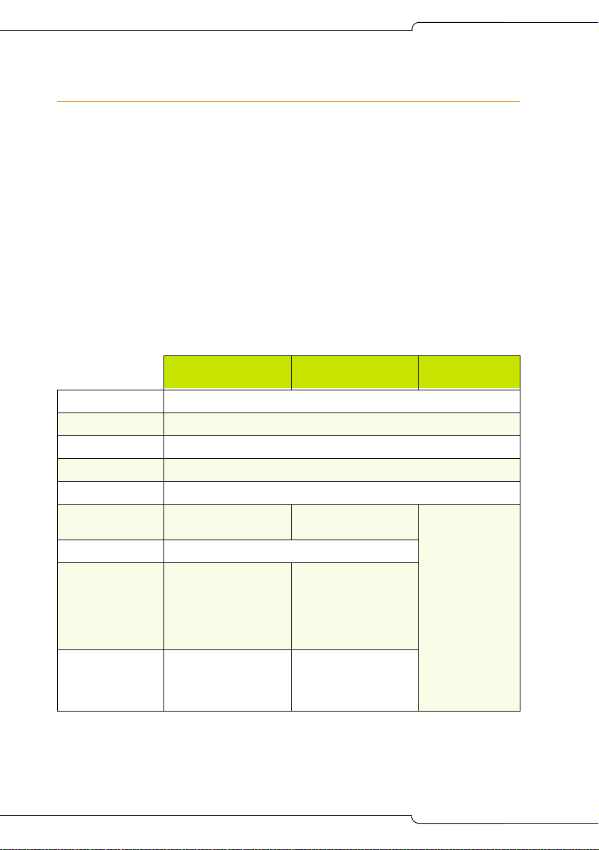
Table 1: SX-200 ICP MX System Packages
Basic Business -
Voice Only
LS/CLASS circuits 6
ONS circuits 2
DNIC circuits 2
Voice mail ports 4
DSPs 1 Dual DSP Module
IP Phones Seven 5207s
PKMs One 12-Button PKM
Licenses
IP Phone
Voice Mailbox
TDM
ACD Agent
IP Channel
Software Options 1 Digital Link
One 5220
16
16
44
None
None
Voice Mail Softkey
Premier Business
- Voice & Data
Four 5220s
8
8
32
5
2
1 Digital Link
Voice Mail Softkey
2nd Port on IP Phones
Record a Call
Basic
Controller
None
8
Page 19
Introduction
System configurations
The controller is configured at the factory as a square key telephone
system (KTS). It can be reconfigured as a PBX or hybrid PBX/KTS by
reprogramming the default database or by installing one of the alternate
databases supplied on the software CD-ROM. For more information about
alternate databases, see page 205. Both configurations are expandable
through the purchase of additional components, including DSP resources
(see “DSP Configuration Options” on page 12 for more information).
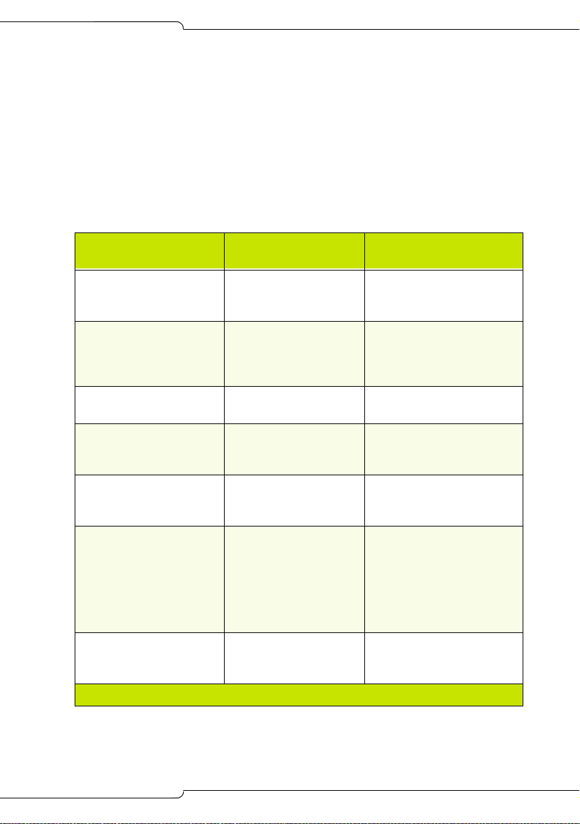
Table 2: SX-200 ICP System MX Configuration
Basic
Configuration
Expanded
Configuration
How Expanded
6 LS/CLASS circuits
(Controller)
2 ONS/CLASS circuits
(Controller)
2 DNIC circuits
(Controller)
0, 8, or 20 IP Phone
licenses depending on
system package
0, 4, or 8 IP Phones
depending on system
package
0, 4, or 20 ports of voice
mail depending on
system package
0 or 4 voice mail user
licenses depending on
system package
12 (Controller)
More than 12
4 (Controller)
More than 4
More than 2 Add Peripheral Bays (6
248 IP Phone licenses
and 24 IP trunks
Maximum 248 IP Purchase additional
24 ports
More than 24
748 Purchase additional
Add Analog Options Card
Add Peripheral Bays (6
max)
Add Analog Options Card
Add ASU (2 max)
Add Peripheral Bays (6
max)
max)
Purchase additional
licenses
Expand Ethernet Switch
licenses and phones
Purchase Options and
DSP resources
(incremental)
Add standalone voice mail
system or Peripheral Bays
with Mitel Express
Messenger card(s)
licenses (incremental)
(Page 1 of 2)
9
Page 20
SX-200 ICP MX Technician’s Handbook
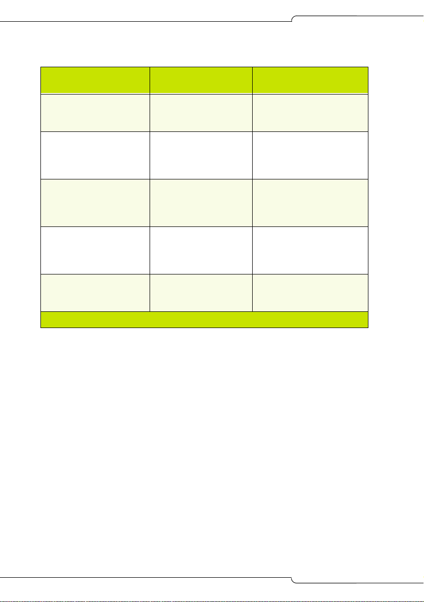
Table 2: SX-200 ICP System MX Configuration (continued)
Basic
Configuration
Expanded
Configuration
How Expanded
Approximately 5 hours of
voice mail message
Depends on capacity of
upgraded media
Install hard drive
storage
Three 3-party
conferences
21 3-party Conferences
(total 21 conferees –
Purchase DSP resources.
can have up to 5
parties per conference)
256 MB of
Larger capacity media Install hard drive
CompactFlash memory
for database storage
(inside controller)
Dual DSP MMC 2 dual DSP MMC or 1
Purchase modules
dual and 1 quad DSP
MMC or 2 quad DSP
MMC
0 Links PRI-T1 4 Links PRI-T1 Purchase 2 NSUs or 2
Peripheral Bays with PRI
cards
(Page 2 of 2)
10
Page 21
SX-200 ICP MX
WIRELESS
PHONES
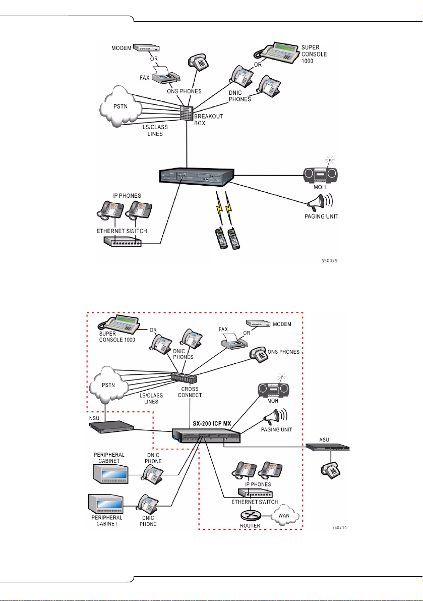
Figure 1: Basic System
Introduction
Figure 2: Expanded System
11
Page 22
SX-200 ICP MX Technician’s Handbook
DSP Configuration Options
The SX-200 ICP MX has six DSP configurations selectable in CDE Form 04:
• Business Option 1
• Business Option 2
• Hospitality Option
• Analog Option 1, 2, and 3
The table below lists the DSP requirements for each of the DSP
configuration options. The requirements are guidelines only; the actual
number of DSPs required depends on the intended use of the system.
Table 3: DSP Configuration Options
Option Type
Business
Option 1
IP
(see Note)
Business
Option 2
IP
Hospitality
Option
IP+TDM
Analog
Option 1
Base Dual DSP
(2 total)
3 conf x 3
parties
4 voice mail
8 G.729
48 IP
6 DNIC/ONS
12 LS/Class
8 conf x 3
parties
8 voice mail
0 G.729
48 IP
6 DNIC/ONS
12 LS/CLASS
8 conf x 3
parties
8 voice mail
0 G.729
96 DNIC/ONS
12 LS/CLASS
2 conf x 3
parties
6 voice mail
0 G.729
24 IP
288 DNIC/ONS
12 LS/CLASS
48 T1 or 76 PRI
2 Dual DSP or
1 Quad DSP
(4 total)
8 conf x 3
parties
12 voice mail
8 G.729
96 IP
6 DNIC/ONS
12 LS/Class
24 T1 or 23 PRI
12 conf x 3
parties
18 voice mail
0 G.729
96 IP
6 DNIC/ONS
12 LS/CLASS
24 T1 or 23 PRI
8 conf x 3
parties
12 voice mail
8 G.729
48 IP
96 DNIC/ONS
12 LS/CLASS
48 T1 or 46 PRI
8 conf x 3
parties
18 voice mail
0 G.729
48 IP
288 DNIC/ONS
12 LS/CLASS
72 T1 or 69 PRI
Add Quad DSP
(6 total)
12 conf x 3
parties
18 voice mail
16 G.729
96 IP
96 DNIC/ONS
12 LS/Class
48 T1 or 46 PRI
18 conf x 3
parties
24 voice mail
8 G.729
96 IP
96 DNIC/ONS
12 LS/CLASS
48 T1 or 46 PRI
12 conf x 3
parties
18 voice mail
16 G.729
96 IP
192 DNIC/ONS
12 LS/CLASS
48 T1 or 46 PRI
12 conf x 3
parties
24 voice mail
0 G.729
96 IP
288 DNIC/ONS
12 LS/CLASS
72 T1 or 69 PRI
2 Quad DSP
(8 total)
12 conf x 3
parties
24 voice mail
24 G.729
192 IP
192 DNIC/ONS
12 LS/CLASS
96 T1 or 92 PRI
21 conf x 3
parties
24 voice mail
16 G.729
192 IP
288 DNIC/ONS
12 LS/CLASS
96 T1 or 92 PRI
12 conf x 3
parties
24 voice mail
16 G.729
248 IP
384 DNIC/ONS
12 LS/CLASS
96 T1 or 92 PRI
21 conf x 3
parties
24 voice mail
0 G.729
192 IP
384 DNIC/ONS
12 LS/CLASS
96 T1 or 92 PRI
(Page 1 of 2)
12
Page 23
Table 3: DSP Configuration Options (continued)
Option Type
Analog
Option 2
Analog
Option 3
(Requires
Quad DSP)
Notes:
Base Dual DSP
(2 total)
2 conf x 3
parties
4 voice mail
0 G.729
24 IP
384 DNIC/ONS
12 LS/CLASS
48 T1 or 46 PRI
2 Dual DSP or
1 Quad DSP
(4 total)
10 conf x 3
parties
12 voice mail
0 G.729
48 IP
384 DNIC/ONS
12 LS/CLASS
48 T1 or 46 PRI
8 conf x 3
parties
12 voice mail
0 G.729
96 IP
576 DNIC/ONS
12 LS/CLASS
96 T1 or 92 PRI
Add Quad DSP
(6 total)
12 conf x 3
parties
16 voice mail
0 G.729
48 IP
480 DNIC/ONS
12 LS/CLASS
48 T1 or 46 PRI
Introduction
2 Quad DSP
(8 total)
21 conf x 3
parties
24 voice mail
0 G.729
96 IP
480 DNIC/ONS
12 LS/CLASS
48 T1 or 46 PRI
(Page 2 of 2)
1. The number of conference, voice mail, and compression
resources is fixed by the purchased option and the number of
DSP devices available; the other values are adjustable.
2. The SX-200 ICP supports the G.711 and G.729a codecs.
- The G.711 PCM audio codec for 56/64 kbps generally
provides the best voice quality and is comparable to TDMtype connections.
- The G.729a audio codec for 8/13 kbps provides a good
reduction in bandwidth with only minor loss in voice quality.
- A purchasable MOSS option controls the number of G.729a
codecs available to IP devices in the system. Compression
enables more devices to share available bandwidth.
- The option is purchasable in multiples of 8 to a maximum of
24. The default value is 0. The quantity entered must exactly
match the quantity on the MOSS sheet.
13
Page 24

SX-200 ICP MX Technician’s Handbook
3. Installation of a hard drive is strongly advised for systems that
have more than eight voice mail ports or when Record a Call is
frequently used.
4. The MX controller can support 12 LS/CLASS, 2 DNIC, and 4 ONS
on the internal analog boards in all option configurations.
5. All T1 trunk quantities include any combination of T1/D4 or
T1/PRI.
6. The maximum system capacity is 672 TDM (ONS/DNIC) ports. In
any option configuration, trunks may be added up to a maximum
of 8 digital links (192 trunks) but only by reducing the number of
digital bays (ONS and DNIC ports) connected, so that the total
number of TDM ports does not exceed that shown in the table.
7. If System Option 82 is enabled (DSP Echo Cancellers), then one
DSP device is removed from the available pool. The number of
TDM resources (voice mail and conference) will be reduced. This
option cannot be used in a base system with compression
enabled (Business Option 1) or with a large number of TDM
devices (Analog Options 1 and 2).
Cabinet Configuration Rules
The MX controller can be expanded to include:
• up to seven SX-200 Peripheral cabinets which provide 672 TDM ports
for ONS, OPS, DID, T1, PRI/T1
• up to four Universal NSUs which provide eight PRI Links (192 PRI/T1
trunks)
• up to two offboard ASUs which provide 48 ONS/CLASS circuits
14
Page 25
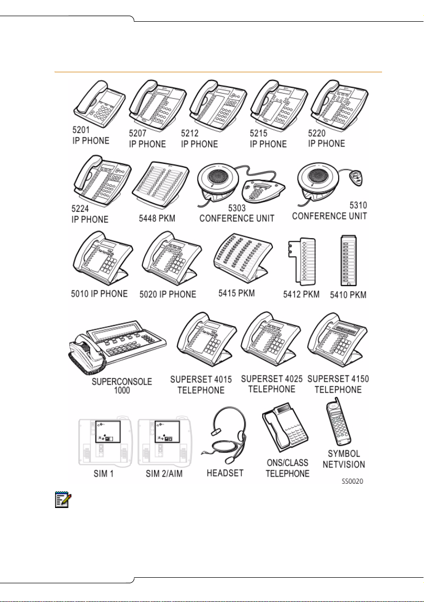
Supported Peripherals
Introduction
Note: The SX-200 ICP (R2.1 or later) also supports the Dual Mode (or DPLite)
5215 and 5220 IP phones. The Dual Mode phon es look the same as the original
5215 and 5220 phones. Check the label on the underside of the phone to
determine which type it is. The originals are identified as 5215 or 5220 “Dual
Port.”
15
Page 26

SX-200 ICP MX Technician’s Handbook
Default Database Configuration
The CDE Forms are factory-set with default values that make it easier and
faster to program the system. The defaults allow you to install the
SX-200 ICP in a square KTS (key telephone system) configuration with up
to 20 IP phones and two analog terminals (phone, fax, or modem) and
make extension-to-extension calls without doing any programming. You
will also be able to receive fax and modem calls, but will have to program
ARS to make external calls from ONS devices.
Two alternate databases are provided on the SX-200 ICP software CD: a
blank database that has no programming and a Premier database for the
SX-200 ICP Premier system. A database programmed with 4-digit extension
numbers is also available on Mitel Online. See page 205 for more
information about the alternate databases and how to install them.
The default database includes the following:
Telephone related
• 3 digit extension numbers that start at extension 100
• IP phone extensions that start at extension 102
• Ports on the Controller
- 6 LS CLASS
- 2 ONS (extensions 201 and 202)
- 2 DNIC (extension 198 is the SUPERCONSOLE 1000
the sub attendant.)
• 7 default classes of service (COS 1 – 7). They are for IP Phones, ONS,
Subattendant, Attendant Console, LS/CLASS, Voice Mail, and IP trunks.
• default key programming on the sets for a 6-line square system
• default ring cadences
• all phones assigned to paging group 1
• the handsfree microphone is not automatically turned on when
receiving a page (auto-latched).
16
®
and 199 is
Page 27

Introduction
Voice mail related
• 4 Voice mail ports (Business 1 Option with Dual DSP); 8 ports
(Business 2 and Hospitality Options with Dual DSP)
• 20 Voice mail mailboxes are assigned with the same extension
numbers as the
- first 20 IP phones (extension 100 to 119)
- Attendant Console (SUPERCONSOLE 1000; extension 198)
- Subattendant (extension 199)
- 2 ONS ports (extensions 200 and 201)
• Hunt Group for Voice mail ports with pilot number 300
- COS 6 and
- reserve extension 301 to 304 for voice mail port extensions
• system-wide Call Forward No Answer to voice mail for all calls.
Trunk related
• trunks in form 14 are non-dial-in to the CO line keys
• LS trunk circuit descriptor defaulted as CLASS
• one LS trunk programmed to Key 1 on IP Phones
• no ARS, no dial 9 for trunk access
System related
• default system options
• default feature access codes
• the default music port (located on the analog mainboard) is ON
• the default paging port (located on the analog mainboard) is ON
• the night bell extension is 340
• SMDR/CDE Print default to ON
• default DHCP settings and a SX-200 ICP Controller default IP address
(192.168.1.2) to match (factory-set).
Note: See Appendix A for a list of default values in the programming forms.
17
Page 28

SX-200 ICP MX Technician’s Handbook
18
Page 29

Chapter 2
Basic Installation
Page 30

SX-200 ICP MX Technician’s Handbook
20
Page 31

Basic Installation
Before you begin
A successful installation of the SX-200 ICP MX depends on careful
planning, especially when integrating the system into an existing data
network.For detailed planning information, see the Engineering Guidelines
in the Documentation folder on the SX-200 ICP software CD-ROM.
Appendix B of the Handbook provides a summary of the Guidelines.
CAUTION:Only experienced network administrators should
integrate the SX-200 ICP MX into a customer's LAN.
21
Page 32

SX-200 ICP MX Technician’s Handbook
Quick Installation
You can quickly install a system configured with Business Option 1 if your
installation does not require any purchasable MOSS Options or optional
controller hardware.
If you are adding MOSS Options, complete the installation by enabling the
options in CDE Form 04, System Options/System Timers. For more
information, see, “Enabling MOSS Options” on page 86.
If you have optional controller hardware to install, follow the procedure on
page 31.
Note: Premier Business systems use the Premier database which must be
installed before enabling the MOSS Options. For more information, see
“Installing an Alternate Database” on page 205.
To install a basic system:
1. Mount the controller.
2. Connect the ground lug at the back of the controller to a ground
connection.
3. Connect the hardware:
- Connect an Ethernet Switch to the Controller’s Ethernet port with a
Cat 5 cable.
Note: The Ethernet port on the controller is auto-sensing, allowing you to
use either a crossover or a straight-through cable.
- Connect the IP phones to the Ethernet Switch ports using Cat 5 cable.
- Connect a breakout box to the amphenol connector at the back of
the controller. For amphenol connector Onboard Analog/DNIC Tip
and Ring Assignments, see page 367.
- Connect the LS CLASS lines and any ONS and DNIC phones to
the breakout box.
- Connect a Music on Hold source, Pager, Night Bells, and any other
optional devices to the back of the controller; see pages 72-74 for
details.
4. Power up the controller.
• The Alarms LEDs on the controller flash and the IP Phones display
IP addresses.
22
Page 33

Basic Installation
5. Wait while the controller boots up.
• The boot sequence is finished when the Major Alarm LED is the
only flashing LED and the IP phones display “Use SuperKey to
send PIN.”
• All phones connected to the controller are now functional.
6. Enter the IP Set Registration PIN numbers on the IP phones (default
*** + extension number).
7. Verify that the system is working; see “System Health Check” on
page 77.
23
Page 34

SX-200 ICP MX Technician’s Handbook
SX-200 ICP MX Hardware
Hardware ports and connectors
Figure 3: Controller front panel
24
Figure 4: Controller rear panel
Page 35

Controller components
Basic Installation
Figure 5: Controller Components
25
Page 36

SX-200 ICP MX Technician’s Handbook
Identify the required components
The range of possible system configurations is determined by the type and
number of controller components and external units (NSUs and Peripheral
Cabinets) included.
Table 4: System Components
System components Capabilities
Basic Controller • 6 LS/CLASS, 2 ONS/CLASS and 2 DNIC
circuits
• 2 PFT (Power Fail Transfer) circuits
• MOH (Music On Hold) port to connect an
external audio source
• Loudspeaker port to connect to an external
paging system
• Dry contacts for Alarm, Door Opener Relay and
Auxiliary Ringer
• RS232 ports for Printer and Maintenance
• Onboard Real-Time Clock
• 2 CIM ports to support up to 2 TDM/Digital Bays
• Internal 256 MB CompactFlash card or hard
drive for system software and database storage
Optional components:
Analog Option Board Provides 6 additional LS/CLASS and 2
ONS/CLASS circuits.
Dual or Quad DSP MMC Provides more resources for conferencing, voice
mail and other applications.
Stratum 3 clock module For digital trunks.
Quad CIM Module Four ports that provide connectivity to Peripheral
Cabinets or NSUs.
Dual FIM Module Two ports that provide connectivity to Peripheral
Cabinets or NSUs.
Dual T1/E1 Framer Module
(Rev. 3)
26
Two ports that provide connectivity to T1/D4 or PRI
trunks.
(Page 1 of 2)
Page 37

Basic Installation
Table 4: System Components (continued)
System components Capabilities
Hard Drive Replaces the internal CompactFlash card to
provide more database storage. (Note: System is
available with factory-installed hard drive.)
Network Services Unit Supports digital trunk protocols for ISDN PRI
Analog Services Unit Provides 24 ONS/CLASS circuits.
SX-200 EL Peripheral
Cabinets
CompactFlash card 256 MB; for on-site software installation upgrades.
(NI2_STANDARD, NI2_5ESS, NI2_GTD5), and
QSIG (QSIG_ISO), DMS 100/250, 4ESS
Up to seven Peripheral Cabinets can be connected
to provide 672 TDM ports.
(Page 2 of 2)
Installation checklist
Tools
Static strap
Phillips screwdriver (#1 and #2)
Use proper fitting screwdrivers to prevent damaging components
and fasteners.
System Hardware and Software
An SX-200 ICP MX Controller
Optional hardware (see the previous table)
Release 3.0 software
A Layer 2 Ethernet switch
IP phones
CompactFlash memory card: 256M minimum (not required if using
FTP to upgrade software on Release 1.0 systems.)
27
Page 38

SX-200 ICP MX Technician’s Handbook
Cables and connectors
Category 5 (CAT5) cable for all LAN devices (IP phones and computers)
CAT3 cable for any analog phones connected to the system
RJ45 cable and connectors
RJ45 crossover cable
Up to ten CIM cables to connect the SX-200 ICP Controller to
Peripheral Cabinet(s), NSUs and ASUs.
FIM or CIM cables if connecting Peripheral Cabinets or NSUs or ASUs
A power cable for the SX-200 ICP Controller (supplied)
Cable plugs must meet FCC Rules part 68 subpart F for
dimensions and registration. Use of non-conforming plugs can
cause intermittent connections.
PC requirements
Windows NT/98/2000/ME/XP PC or laptop
Internet Explorer version 5.5 with service pack 2, or version 6
(recommended) for client-side rendering and 128 bit encryption
(required for access to Mitel Online).
Network Interface Card: Full Duplex 10/100M (100M recommended)
a serial cable to connect a PC to the SX-200 ICP Controller
FTP Server—used for software upgrades, database backups, and
uploading maintenance logs
CompactFlash Reader with Read/Write capability
(Optional) secure Telnet client that supports SSL/TLS (Mitel Telnet
client recommended)
Line requirements
LS/CLASS lines
ONS/CLASS lines
PRI-T1 lines (requires a Dual T1/E1 Framer Module, a Dual FIM
Module connected to a Network Services Unit, or a Dual FIM or Quad
CIM Module connected to a Peripheral Cabinet and PRI card)
28
Page 39

Basic Installation
LAN requirements
Pre-installation questionnaire complete
A subnet
(Advanced) SMTP server IP address for forwarding voice mail to
e-mail and for e-mail notification of 911 calls and system alarms
(Advanced) IMAP Server IP address for forwarding voice mail to e-mail
(Advanced) Customer data network information (for example, DNS
server information)
(Advanced) Router if using IP trunking or connecting to the Internet or
other network
IP Address Requirements
You need IP addresses for
• The SX-200 ICP Controller
• Each IP phone (a range of IP addresses assigned by the DHCP Server
or statically assigned)
• A router or gateway (if using)
Important: The SX-200 ICP Controller uses the following reserved
IP addresses:
192.168.10.1 - 192.168.10.255
192.168.11.1 - 192.168.11.255
192.168.12.1 - 192.168.12.255
192.168.13.1 - 192.168.13.255
Ensure no other devices on the network use IP addresses within
these ranges.
Other
Feature codes and extension number plans
A list of customer-purchased options
An uninterruptible power supply (recommended)
Power source with surge protection for IP Phones; see page 32 for
powering options.
(Optional) Music on Hold source (radio, tape player etc.)
29
Page 40

SX-200 ICP MX Technician’s Handbook
(Optional) External paging amplifiers and speakers
(Optional) Auxiliary ringer (Night Bells)
(Optional) Door Phone/Opener
(Optional) Alarm device to signal system alarms
(Optional) SMDR printer
Installation overview
Install SX-200 ICP Controller
Install optional controller hardware
Install an Ethernet switch
Feed power to the IP Phones
Initialize the System
(Optional) Load software on an External CompactFlash Card
(Optional) Install NSU
(Optional) Install ASU
(Optional) Install SX-200 Peripheral Cabinets
(Optional) Install Music on Hold, Paging, Auxiliary Ringer, Door
Phone/Opener, and Alarm Device
Connect the Phones and Lines
(Optional) Install Programmable Key Modules
Install an FTP Server
Verify the system
30
Page 41

Basic Installation
Installing the SX-200 ICP MX Controller
The SX-200 ICP system is shipped with the system software and a default
database installed. The optional components (DSP modules, Analog
Option Module, etc.) are field-installed.
Note: Premier Business systems use the Premier database which must be
installed before enabling the MOSS Options. For more information, see
“Installing an Alternate Database” on page 205.
1. Install optional controller hardware or peripheral units according to the
instructions on the pages indicated.
Analog Option Board: page 39
DSP Modules: page 41
Dual FIM Module: page 43
Quad CIM Module: page 44
Dual T1/E1 Framer Module: page 45
Upgraded Internal CompactFlash or Hard Drive: page 46
Stratum Clock Module: see page 48
Network Services Unit, page 54
SX-200 Peripheral Cabinets, age 57.
2. Wall mount the units, rack mount them, or place them on a desk or
shelf; see page 32 for instructions.
Note: The NSU is NOT wall-mountable.
3. Connect the ground stud on the rear panel of the controller to a hard-
wired ground using 18 AWG (0.75mm 2/) gauge wire. The wire must
have green or yellow insulation. Crimp the wire to the ground source.
4. Connect a PC to the Maintenance port on the controller; see page 82.
5. Connect the trunks and phones. See “Connecting the Phones and
Trunks” on page 66.
6. If you are NOT installing software or optional hardware in the controller,
power up the system.
31
Page 42

SX-200 ICP MX Technician’s Handbook
Install an Ethernet Switch
You must connect all IP devices to a Layer 2 Ethernet Switch. Hubs should
not be used. The type of Ethernet Switch required depends on the number
of IP Phones you need to install.
Important: Careful planning is essential when installing the
SX-200 ICP for voice and data. For planning information, including
a pre- installation questionnaire, see Chapter 4, Advanced
Installation and Programming.
Small installations (under 20 phones)
• Connect the Ethernet Switch to the SX-200 ICP Controller Ethernet
Port with an Ethernet cable.
The Ethernet port on the Controller is auto-sensing, allowing you to
use a crossover or straight-through cable.
• Connect the Ethernet Switch power cord to a power source.
32
Page 43

Basic Installation
Larger installations (over 20 phones)
If you are connecting several switches together, connect them in a
tree-type structure. Daisy-chaining switches is not recommended because
all switches become involved in connections from one end of the chain to
another. Layering reduces this unnecessary traffic.
33
Page 44

SX-200 ICP MX Technician’s Handbook
Feeding Power to IP Phones
The IP Phones require power that can be provided by
• an external supply such as a 24-volt adapter (required by the 5010 and
5020 IP Phone; connects to back of phone) or 48-volt power brick
(required by 5200 series IP Phones; see Figure 6 for connections).
• a multi-port Ethernet Inline Power Module (such as the PowerDsine
24PT Inline Power Unit)
• Layer 2 switches with integral power feed
None of the above are included with the system or phones. All except the
powered Layer 2 switch can be ordered from Mitel. See Appendix B for
part numbers.
Note: Power backup to the IP Phones, the SX-200 ICP, and the Ethernet
switches is required to maintain service during a power failure.
CAUTION:Ensure that the powered cable from the inline power
adapter is installed in the proper connector on the IP Phone. DO
NOT plug it in to the connector (if available) designed for a PC
or other Ethernet devices (Layer 2 port).
Figure 6: Power Brick Connections for 5200 Series IP Phones
34
Page 45

Basic Installation
Installing Software Using an External CompactFlash Card (Optional Initial Install)
The SX-200 ICP is shipped from the factory with the system software and
a default database installed. Perform this procedure only if you,
• are upgrading the system software on site
• are upgrading Release 2.0 or later software
Note: Systems with Release 1.x software can only be upgraded on site using
a CompactFlash card. For more information, see “Upgrading the System
Software” on page 206.
• require a language other than the default English for voice mail prompts
or a second language for bilingual voice mail operation
• are replacing the internal CompactFlash or installing a hard drive. For
replacement instructions, see page 199
• are re-initializing the controller by re-installing the system software
Note: The “Initial” power-up and the reset in this procedure will each take 5
to 10 minutes.
To install software using an external CompactFlash card:
Important: Use only Mitel-supplied CompactFlash cards. DO NOT
partition the card and DO NOT copy files to it before proceeding
with the software installation.
1. Launch the SX-200 ICP Installation program on the supplied
CD-ROM.
2. Select “Initial [CompactFlash Card] Installation”, and then click Next.
3. Select the voice mail language(s) that you want to install, and then
click Next The default is English and is not selectable.
Note: The additional languages enable the embedded voice mail system to
operate with bilingual prompts. Bilingual prompts is a purchasable MOSS
option.
4. Specify the drive letter of the CompactFlash Writer/Reader.
35
Page 46

SX-200 ICP MX Technician’s Handbook
5. Select Format to format the CompactFlash card.
Note: When formatting the CompactFlash card, specify FAT as the file
system.
6. Select a database, then click Next.
7. Click Next to begin installing the software on the CompactFlash card.
8. Click Finish to complete the installation.
Note: Wait until the computer completes writing to the CompactFlash
card before removing it
EJECT.
Note: Certain PC CompactFlash readers have problems with cards larger
than 128M. They report that copying is complete when in fact not all the files
have been copied. If in doubt, eject the card, re-insert it, and then use
Windows Explorer to confirm that all 37 files (64 if a second language for
voice mail was installed) are present.
. To ensure completion, DO NOT click STOP before
9. Insert the CompactFlash card into the controller.
10. Press the RESET button on the controller or power it down then back up.
The system boots from the CompactFlash card, and then runs the
install utility. When installation is complete, the system automatically
reboots.
Do not remove the CompactFlash card while the system is
rebooting as indicated by the LED adjacent to the card slot.
Wait for the LED to turn green before removing the card.
IMPORTANT: Re-initializing a working system with a database
that has different IP addressing information than the database it is
replacing will force the IP Phones to reboot. The phones take 10 to
15 minutes to return to service once the system is re-initialized.
11. Remove the CompactFlash card from the controller when the LED
adjacent to the card slot turns green.
IMPORTANT: If the card was removed and reinserted (or replaced
by another card), the system will detect it and attempt an upgrade
or installation when it reboots. Both processes take the system out
of service. To prevent unnecessary loss of service, always remove
the external card once the system is up and running.
12. Log in to CDE and enable MOSS sheet options (if any) in Form 04.
36
Page 47

Basic Installation
Installing Optional Controller Hardware
• Hard drive or larger internal CompactFlash
• Analog Option Board
• Dual FIM Option Module
• Quad CIM Module
• Dual T1/EI Frame Module
• Stratum Clock Module
• Dual or Quad DSP Option Modules
Precautions
WARNING: INSTRUCTIONS MUST BE FOLLOWED EXPLICITLY
WHEN THEY INVOLVE WORK WITH AND CHANGES TO THE
PRIMARY POWER SUPPLY OF THE UNIT.
Observe the following precautions when working on the system, particularly
when handling PCB cards or using test equipment to measure voltages.
• When installing or replacing PCB cards turn power off, but maintain
the ground connections to the equipment (see Note below). Power
must be OFF when inserting or removing cards. These cards are
identified with appropriate warnings on their faceplates.
• Always wear an antistatic wrist strap when handling printed circuit
cards. Handle PCB cards only by the edges and avoid contact with any
exposed electrical connections. When removing a new card from its
package, touch the package to the cabinet frame first to release any
static voltage buildup, prior to removing the card and inserting it into
the equipment.
• Conductive packages (antistatic packaging) should be grounded prior
to opening them to remove the contents, and similarly grounded prior
to placing a card in the package. Place suspected faulty cards in
conductive packages to prevent further possible damage to the cards.
Cards that are not correctly packed in antistatic packaging when
returned will not be covered by any warranty.
Use proper fitting Phillips screwdrivers (#1 or #2) to prevent
damaging components and fasteners.
37
Page 48

SX-200 ICP MX Technician’s Handbook
Removing the cover
To remove the SX-200 ICP Controller cover:
1. Unplug the power cord from the controller and disconnect all cables.
2. Remove the controller from the rack or wall and place it on a suitable
work area (if applicable).
3. Remove the four screws from the top of the controller.
4. Slide the cover forward until it catches, then tilt the cover upward to
remove it.
5. Remove the front faceplate by clipping it off from the bottom of the unit.
Note: It may be easier to pry the end off first, and then slide your fingers along
the bottom edge of the faceplate to the other end.
.
38
Page 49

Basic Installation
To replace the cover:
1. Turn the controller until the back panel is facing forward.
2. Lift the lock for the AC power cord and place the cover at an angle to
hook onto the back of the unit.
3. Straighten and slide the cover forward as far as it will go.
4. Secure the cover by inserting and snugly securing the two screws on
the back panel.
5. Rotate the controller until the front panel is facing forward.
6. Secure the screws on the top of the unit.
7. Clip on the front face-plate taking care not to damage the protruding
FIM connectors.
8. Reinstall the controller on the wall or in the rack (if applicable).
9. Reconnect all cables.
Install the Analog Option Board (AOB)
1. Unplug the power cord from the controller.
2. Remove the cover and the front panel.
3. Remove the Stratum Clock Module (if installed).
4. Attach the standoffs as shown in the following figure.
39
Page 50

SX-200 ICP MX Technician’s Handbook
5. Lower the AOB onto the standoffs. Ensure it is well-seated.
6. Attach the screws.
7. Re-install the Stratum Clock Module (if it was removed).
8. Replace the cover and the front panel.
9. Connect lines or devices to the AOB ports and complete the required
programming; see the following sections for more information:
ONS telephones: “Connecting the Phones and Trunks” on page 66
and “Programming a Single Line Voice Station” on page 110
LS trunks: “Connecting the Phones and Trunks” on page 66 and
“Programming Analog Trunks” on page 131
Relays: “Connecting Music on Hold, Paging and Door Phone/Door
Opener” on page 72 and “Connecting a Night Bell and Alarm Device”
on page 74
Paging: “Connecting Music on Hold, Paging and Door Phone/Door
Opener” on page 72.
40
Page 51

Basic Installation
Installing Optional DSP Module(s)
The basic SX-200 ICP MX has one Dual DSP module installed in Module
Slot 3. Additional DSPs can be added by installing Dual or Quad DSPs
modules in the Module Slots 2 and 3 as shown in the following figure. For
information on determining DSP requirements, see “DSP Configuration
Options” on page 12.
41
Page 52

SX-200 ICP MX Technician’s Handbook
To install the optional DSP Modules:
1. Unplug the power cord from the controller.
2. Remove the top cover.
3. Repeat the steps below for each DSP module you install:
- Remove the DSP module from its packaging.
- Remove the blanking panel covering the Module Slot into which
you are installing the DSP Module.
- Remove the small PCB (
- Install the module cover on DSP module (
).
).
- Insert the DSP module in the appropriate slot.
- Secure the DSP module to the controller using the screws provided.
4. Replace the cover.
42
Page 53

Basic Installation
Installing the Optional Dual FIM Module
The Dual FIM Module provides connectivity to a Peripheral Cabinet and/or
to an NSU. The MX can support up to two Dual FIMs installed in MMC slots
1 and 2.
There are three fiber length variants of the FIM Module: 1, 5, or 14 km.
Both ends must use the same variant.
Notes:
1. The NSU supports the 1 km variant only.
2. The SX-200 ICP does not support single FIM modules.
To install a Dual FIM Module:
1. Unplug the power cord from the controller.
2. Remove the top cover and the front panel.
3. Insert the new FIM II Module into Module slot 1 or 2 on the Main Board
connector.
4. Attach the screws.
5. Replace the front panel and the top cover.
43
Page 54

SX-200 ICP MX Technician’s Handbook
Installing the Optional Quad CIM Module(s)
The optional Quad CIM module has four ports that provide connectivity to
Peripheral Cabinets, NSUs, and ASUs using Category 5 UTP copper cabling.
The system can support up to two Quad CIM Modules installed in Module
slots 1 and 2.
To install a Quad CIM Module:
1. Unplug the power cord from the controller.
2. Remove the top cover and the front panel.
3. Insert the Quad CIM into Module slot 1 or 2 on the Main Board
connector.
4. Attach the screws.
5. Replace the front panel and the top cover.
44
Page 55

Basic Installation
Installing the Optional Dual T1/E1 Framer Module(s)
The Dual T1/E1 Framer module has two digital trunk ports, each of which
can be programmed to support either T1/D4 or PRI. Up to two modules can
be installed in MMC slots 1 and 2 of the MX controller.
The system can support up to two Dual T1/E1 Framer Modules installed in
Module slots 1 and 2.
To install a Dual T1/E1 Framer Module:
1. Unplug the power cord from the controller.
2. Remove the top cover and the front panel
3. Insert the Dual T1/E1 Framer into Module slot 1 or 2 on the Main Board
connector.
4. Attach the screws.
5. Replace the front panel and the top cover.
6. Program the module in CDE:
- Assign the module a bay number in Form 53, Bay Location.
- Program the T1 link; see page 130.
45
Page 56

SX-200 ICP MX Technician’s Handbook
Installing a hard drive
The SX-200 ICP is shipped with an internal CompactFlash card which
provides 256 MB of memory for system software and database storage. If
you need increased storage capacity for voice mail messages and
recorded calls, you can replace the card with a MItel-supplied hard drive.
(see Appendix C on page 351 for the part number).
Notes:
1. A hard drive is strongly recommended for systems that have
more than eight voice mail ports or when Record a Call is
frequently used.
2. Use Mitel-supplied hard drives only; those obtained elsewhere
are not supported.
Use this procedure to upgrade systems only. To replace faulty cards or drives,
use the media replacement procedure on page 199.
To install an optional hard drive:
1. Establish a serial connection to the Maintenance port on the controller.
For instructions, see “Serial Connection to the Controller” on page 82.
2. As a precaution, perform a full database backup; for instructions, see
page 203. Skip this step if the system is new and has no database
changes to preserve.
3. If an external CompactFlash card is inserted in the controller, remove it.
4. Use the System > Restart > Shutdown command in Maintenance to
stop the system.
5. When prompted on the PC, power down the controller.
6. Remove the cover.
7. Remove the internal CompactFlash card. Keep it on hand.
8. Install the hard drive as follows,
a. Remove the drive from its packaging and set the jumpers on the
drive to the Master setting.
46
Page 57

Basic Installation
b. Insert the hard drive as shown in the above figure.
c. Connect the power and IDE cables to the corresponding connectors
on the hard drive and main board. The cables are keyed for proper
connection.
d. Secure the hard drive to the controller using the screws provided.
9. Replace the cover.
10. Insert the internal CompactFlash card previously removed into the
external card slot.
11. Restore power to the controller.
12. Re-establish a serial connection to the controller and wait while the
new media is formatted and the contents of the CompactFlash card
copied to it.
13. When prompted, press return four times to log in to CDE/Maintenance.
14. Verify that the phones are working and that calls can be made.
15. Remove the CompactFlash card from the external slot.
47
Page 58

SX-200 ICP MX Technician’s Handbook
Installing the Stratum Clock
1. Unplug the power cord from the controller.
2. Remove the top cover and front panel.
3. Gently seat the Clock Module onto the Main Board.
4. Attach the screws.
5. Replace the top cover and front panel.
6. To check whether the system recognizes the Stratum clock card, log
into Maintenance and use the System > Show > Identity command. It
should show the clock as ST3.
48
Page 59

Basic Installation
Wall or Rack Mounting
The SX-200 ICP controller is wall and rack mountable. The NSU is
rack-mountable only.
Wall mounting the controller
When mounting the controller on a wall, use the supplied long bracket and
small bracket and the supplied screws (#10).
.
CAUTION:Make sure the wall material is capable of supporting
the weight of the unit. Mitel is not responsible for units
damaged as a result of improper wall mounting.
1. Turn the controller upside down.
2. Locate the two holes on the bottom of the Controller as shown in the
following figure.
3. Remove the two feet as shown below.
49
Page 60

SX-200 ICP MX Technician’s Handbook
4. Assemble the two supplied screws and two nuts as shown below.
5. Screw the assembled nuts and screws into the holes as shown below.
50
Page 61

Basic Installation
6. Screw the supplied small bracket onto the bottom of the controller as
shown.
7. Mount the bracket onto the wall.
a. Pre-drill two pilot holes into two wall studs with 16" centers.
b. Orient the bracket over the two holes as shown below.
c. Insert a screw into the hole on the left side of the bracket.
d. Insert a screw into the hole on the slot on the right side of the
bracket.
8. Hang the controller onto the mounted bracket as shown below.
Position it with the front panel facing to one side so that the ports and
connectors are accessible.
51
Page 62

SX-200 ICP MX Technician’s Handbook
.
9. Insert a screw into the bottom bracket to stabilize the controller as
shown below.
52
Page 63

Basic Installation
Rack mounting the controller or NSU
Use the Rack Mount Kit (Part Number: 50004150) to rack mount the
Controller. The NSU requires a different kit that is supplied with the unit.
CAUTION:When installing the system in an enclosed rack, you
MUST provide adequate ventilation to ensure that the
maximum ambient temperature inside the rack does not
exceed 40°C/104°F.
CAUTION:Ensure that a hazardous condition does not result
from any uneven mechanical loading.
CAUTION:When using the system in a rack, you should
consider the connection of the equipment to the power supply
circuit and the effect that overloading of circuits might have on
overcurrent protection and supply wiring. When addressing
this concern, refer to the system’s ratings label.
1. Attach the brackets to the rack.
2. Slide the unit into the brackets.
3. Secure the unit to the brackets using the supplied thumbscrews. The
screws fasten to the underside of the unit and fit into the notch on the
bracket.
53
Page 64

SX-200 ICP MX Technician’s Handbook
Installing an NSU
Figure 7: NSU Front View
Figure 8: NSU Rear View
The NSU connects to the Controller via a CIM or FIM cable.
Note: The FIM Module in the controller must be the 1K variant, which
is the only variant that the NSU supports.
1. Mount and secure the NSU in the desired location.
2. Set the L0/L1 port DIP switches to the appropriate termination mode
and impedance; see Figure 9, “NSU DIP Switch Location,” on
page 55. The default is network termination mode (switch 6).
3. Set the two Message Link DIP switches to the down position. The left
switch is partially hidden by the NSU rear panel.
4. Connect a fiber optic cable between the NSU FIM and the controller FIM.
Or, connect a Cat 5 crossover cable between one of the CIM ports on the
NSU and one of the CIM ports on the SX-200 ICP controller.
5. Connect the NSU L0 and/or L1 port to the remote system (the PSTN
or another system). See the table below for the pinout.
6. Install IMAT from the SX-200 ICP software CD.
7. Connect power to the NSU.
54
Page 65

Basic Installation
8. Program the NSU using CDE and IMAT; see page 112 for
programming instructions.
9. After programming the NSU, plug the T1 cable from the demarcation
point for the T1 provided by the Carrier to either L0 or L1 on the back
of the NSU. Each connector (L0 or L1) has LED indicators beside the
connector to indicate sync or not. For example:
- Red LED indicates no sync (check connection or switch 6 is in
wrong position).
- Flashing green LED indicates synch but D-channel is not
synchronized (check programming (see table below) on IMATs to
ensure correct protocol).
- Solid green LED indicates that D-channels and B-channels are all
in sync and PRI trunks on NSU are ready to process calls.
.
Table 5: Pinouts for T1 Line/Network Termination
Pin
1 Tx Ring Rx Ring
2 Tx Tip Rx Tip
3 Unused Unused
Line
Termination Mode
Network
Termination Mode
4 Rx Ring Tx Ring
5 Rx Tip Tx Tip
6 Unused Unused
7 Unused Unused
8 Unused Unused
Figure 9: NSU DIP Switch Location
55
Page 66

SX-200 ICP MX Technician’s Handbook
Table 6: NSU DIP Switch Setting
DIP Switch Function Settings Notes
1
2
3
4
5
6
TX Ground Down: Ground
RX Ground Down: Ground
E1 Twisted Pair
cable selector
(RJ45, PRI)
TI Cable Selector
(T1/D4)
EI, coaxial cable
selector (R2)
Line/Network
Termination
Selector
Up: Floating
Up: Floating
Down: Enabled
Up: Disabled
Down: Enabled
Up: Disabled
Down: Enabled
Up: Disabled
Down: Line
Up: Network
Set to Up
Set to Up
Set to Up
120 ohm impedance
(Europe)
100 ohm impedance
Default - Down
Set to Up
75 ohm impedance
(Europe)
If connecting to Telco, set
switch to Up
56
Page 67

Basic Installation
Installing SX-200 Peripheral Cabinets
You can connect up to seven Peripheral Cabinets to the MX controller via
CIM or FIM cables. The cabinets can be SX-200 ELx peripheral cabinets,
SX-200 LIGHT peripheral cabinets, or a mix of both.
FIM Connectivity
There are three variants of the FIM II modules.The same variant of fiber
interface module (1, 5, or 14 km) must be at both ends.
Note: The SX-200 ICP does not support single FIM modules.
CIM Connectivity
There is only one variant of the CIM. In the peripheral cabinets, a CIM sits
on a Bay Control Card III (BCC III), on a Peripheral Interface Module
Carrier card, or on a PRI card.
• The CIM (Copper Interface Module) supports a distance of up to 30
meters or 100 feet.
• The CIM requires Category 5 UTP crossover cable (TX and RX pairs
reversed) with RJ45 connectors.
57
Page 68

SX-200 ICP MX Technician’s Handbook
Cabinet installation and programming
The following procedure applies to the installation of new peripheral
cabinets. Cabinets migrating from an existing SX-200 EL/ML installation
install in a different manner; see “Migrating an SX-200 EL/ML to an
SX-200 ICP” in the SX-200 ICP Technical Documentation for more
information
1. Install the peripheral cabinet (including Bay Power Supply, Bay Control
Card, interface cards and required Fiber or Copper Interface Module).
2. Complete the peripheral interface cabling.
See Tip and Ring Assignment tables in Appendix C (page 365) for
cabling and cross connecting the peripheral cabinets.
3. Connect one end of the fiber or copper cable to the interface module
in the control cabinet and the other end to the CIM or FIM connector in
the controller.
4. Power up the cabinet.
5. Enter CDE mode on the maintenance terminal.
6. In Form 04 (System Options/System Timers)
- Enable the required number of TDM Bays (Option 133)
- Make sure there are enough TDM devices available (Options 103).
7. In Form 53 (Bay Location Assignment)
- Assign a bay number to the CIM or FIM ports used to connect the
peripheral cabinets.
8. In Form 01 (System Configuration)
- Configure the cards (select node type as required).
9. Complete the remaining CDE programming for the cards.
For detailed programming information, refer to the SX-200 ICP Technical
Documentation.
58
Page 69

Basic Installation
Peripheral Cabinet Interface Cards and Modules
The following table lists the peripheral cabinet interface cards and modules
supported by the SX-200 ICP.
Table 7: Peripheral Cabinet Interface Cards and Modules
Interface Card Devices supported Circuits Maximum loop resistance
DID Trunk card
(high power)
LS/GS Trunk
card
(low power)
LS/CLASS
Trunk card
(low power)
ONS/CLASS
Line card
(low power)
OPS Line card
(low power)
Direct Inward Dial (DID)
trunks from CO
Ground start and Loop
start CO trunks
Loop Start CO trunks 8 not applicable
DTMF telephone sets
Rotary telephone sets
DTMF telephone sets
Rotary telephone sets
6 Loop resistance: 2450 W
(includes set resistance)
Loop length:
26 AWG - 7986 m (25955 ft.)
22 AWG - 19995 m (64984 ft.)
6 not applicable
12 External loop resistance:
600 W (includes set resistance)
External wire resistance:
400 W
External loop length:
22 AWG - 3560 m (11700 ft.)
24 AWG - 2250m (7400 ft.)
6 External loop resistance: 1800 W
(includes set resistance)
External wire resistance:
1600 W
External loop length:
26 AWG - 7225 m (23700 ft.)
22 AWG - 18290 m (60000 ft.)
/loop lengths
(Page 1 of 2)
59
Page 70

SX-200 ICP MX Technician’s Handbook
Table 7: Peripheral Cabinet Interface Cards and Modules (continued)
Interface Card Devices supported Circuits Maximum loop resistance
Digital Line card
(DNIC)
(low power;
high power if a
console is
connected to a
SX-200 LIGHT)
Mitel Express
Messenger
Card
(DNIC, low
power)
Universal card
(high power)
Music-on
Hold/Paging
module
DTMF receiver
module
E&M trunk
module
LS/CLASS
Trunk
module
SUPERSET™ 4001
SUPERSET 4015
SUPERSET 4025
SUPERSET 4090
SUPERSET 4125
SUPERSET 4150
SUPERSET 401+
SUPERSET 410
SUPERSET 420
SUPERSET 430
SUPERSET 3DN
SUPERSET 4DN
DATASET 1100
DATASET 2100
SUPERCONSOLE 1000
SUPERSET 7000
DSS/BLF Interface Unit
MOH/Pager Unit
2, 4, 6, and 8 voice mail
ports
Four modules:
MOH/Paging
DTMF Receiver,
E&M Trunk, Console
DTMF telephone
keypads and end-to-end
signaling equipment.
E&M tie trunk 1 power rating = 3
4 LS/CLASS trunks plus
SFT for circuit 1 (SPINE
Bay only)
12 24 AWG (25 IWG) - 1000 m
(3300 ft.) including up to 50 m
(162.5 ft.) 22 AWG (22 IWG)
quad wire and up to 3 m
modular line cord without bridge
taps
NA NA
Total power rating of modules on
Universal card cannot exceed 10
1 each power rating = 1
loop length - not applicable
4 power rating = 2
loop length - not applicable
26 AWG - 1068 m (3500 ft.)
24 AWG - 1708 m (5600 ft.)
22 AWG - 2715m (8900 ft.)
4 External loop resistance: 1600 W
/loop lengths
60
(Page 2 of 2)
Page 71

Basic Installation
Peripheral Cabinet Control and Digital Services Cards and Modules
The following table lists the peripheral cabinet control and digital services
cards and modules supported by the SX-200 ICP
Table 8: Digital Control and Digital Services Cards and Modules
Card or Module Important Details
Bay Control Card II One for each bay
Bay Control Card III Requires the SX-200 ELx cabinet
T1 Trunk Card A 24 circuit, high power card to CO or to another PBX,
PRI Card For the SX-200 ELx cabinet Rev 4.4 or greater
T1/E1 module Provides up to 2 T1 links of ISDN connectivity (24 or 48
FIM II Installs on the BCC III or the PRI card.
Copper Interface
Module (CIM)
DSP Module (Single) Installs on the BCC III. Provides CLASS functionality for 8
maximum distance is 655 feet of shielded cable to the
Channel Service Unit
(PN 9109-600-002-NA)
Supports the T1/E1 module and the FIM II or CIM. The PRI
card is not included in the high power card count. The PRI
card is a separate bay.
channels) on the PRI card. Provides up to 2 T1 links of T1/D4
connectivity on the BCC III.
Installs on the BCC III or the PRI card.
ONS/CLASS Line cards, 16 DTMF receivers and 16
conference bridges for Record a Call.
61
Page 72

SX-200 ICP MX Technician’s Handbook
Peripheral Cabinet Configuration Rules
FIM Carrier Assignments
• The SX-200 RM peripheral cabinet supports the Peripheral Interface
Module Carrier (FIM II or CIM)
• The SX-200 RM peripheral cabinet supports the Peripheral FIM
Carrier II
• The SX-200 LIGHT peripheral cabinet supports the Peripheral FIM
Carrier
T1 Trunk Card Configuration Rules
• The system software supports up to two T1 links (includes T1 links
from T1/E1 modules and T1 cards) in any bay with a maximum of eight
T1 links in the system.
• The MOSS System Option 96, Number of Links (0-8) monitors how
many T1 links (from T1/E1 modules) that the system will support. This
count includes T1 links from the T1/E1 modules on the PRI cards and
BCC III cards. The count does not include T1 links from the T1 cards.
• PIC slot 5 must be left vacant when a T1 card is installed in slot 10 or
when Link 1 from a T1/E1 module on a BCC III is programmed.
• PIC slot 6 must be left vacant when a T1 card is installed in slot 11 or
when Link 2 from a T1/E1 module on a BCC III is programmed.
Note: Do not insert T1 trunk cards into slots 5 or 6 of a peripheral cabinet.
Digital Line Card Configuration Rules for SX-200 RM Cabinets
Systems with BCC II cards have performance limits:
• In high traffic configurations, keep the Digital Line Card (DLC) count to
a maximum of 7 per bay when using BCC II cards. If you have 8 DLCs
per bay, keep the device count to 84 or less. This will avoid slow
softkey response during peak traffic periods.
• With 2 T1 cards in a bay, do not add more than 5 DLCs or 60 devices.
This avoids dial tone delays during peak traffic periods.
• With 1 T1 card in a bay, do not add more than 6 DLCs or 72 devices.
This avoids dial tone delays during peak traffic periods.
Tip: A BCC III supports 8 DLCs per bay and is therefore ideal for high traffic
conditions.
62
Page 73

Basic Installation
PRI Card Configuration Rules for SX-200 RM Cabinets
• The PRI card requires a Stratum 3 clock MMC installed in the SX-200
ICP controller.
• The peripheral cabinet supports one or two PRI cards in Slot 10 or 11.
Inserting the PRI card in any other slot besides 10 or 11 will cause
the power supply to fail.
• The PRI card will appear as a peripheral bay on the SX-200 ICP
controller, and the two links of the T1/E1 module installed on the PRI
card will appear as slots 5 and 6 on that bay (not on the peripheral
cabinet).
• The PRI card bay number is designated in Form 53.
• The PRI card requires a FIM II or CIM to connect to the SX-200 ICP
controller.
• The S1 switch settings on the PRI Card inform the T1 module of the
location of the clock source. Both switches must be set to closed as
indicated in the following illustration (to designate the interface module
as the clock source).
63
Page 74

SX-200 ICP MX Technician’s Handbook
Installing an ASU
Up to two ASUs can be connected to the controller via CIM ports. There is
no need to power down the controller to make the connection.
Figure 10: ASU Front View
Figure 11: ASU Rear View
To install an ASU:
1. Mount the ASU.
Note: The ASU can be located up to 30 meters (100 feet) away from the
SX-200 ICP.
2. Connect a cross-over Category 5 cable with RJ-45 connector to the
CIM port on the ASU and a free CIM port on the controller.
3. Complete telephony cabling for the ASU. See Appendix C for Tip and
Ring assignments.
4. Connect power to the ASU.
5. Wait for the CIM LEDs to turn on indicating that the CIM link is
synchronized.
6. Program the ASU in CDE.
64
Page 75

Basic Installation
CDE Programming
1. In Form 53 (Bay Location Assignment)
- Ensure that the CIM(s) are NOT assigned bay numbers.
2. In Form 01 (System Configuration)
- Assign the ASU(s) to slots 14 and 15 of the IP bay.
- Configure the card(s)
3. Complete the remaining CDE programming for the cards. See
“Programming a Single Line Voice Station” on page 110.
65
Page 76

SX-200 ICP MX Technician’s Handbook
Connecting the Phones and Trunks
ONS/CLASS, DNIC and LS/CLASS ports
Cross connect the ONS, DNIC and LS/CLASS ports to lines at the
breakout box according to the Amphenol connector pin assignments in
table below.
After connecting the LS trunks, use the Line Quality Test to program the
audio configuration settings. For more information, see “Running the Line
Quality Test for LS Trunks” on page 140.
Table 9: Amphenol Connector Pin Assignments
Pair(s) Circuit Type Bay/Slot/Circuit Default DN
1/26 and 2/27 ONS/CLASS 1/13/3, 1/13/4 200 and 201
3/28 and 4/29 ONS/CLASS 1/13/5, 1/13/6 Unassigned
5/30 Not Used
6/31 and 7/32 DNIC 1/13/1, 1/13/2 198 - SC 1000
8/33 to 10/35 Not Used
11/36 to 16/41 LS/CLASS 1/13/7 - 1/13/12
17/42 to 22/47 LS/CLASS 1/13/13 - 1/13/18
23/48 to 25/50 Not Used
199 - Subattendant
Notes:
1. ONS/CLASS ports do not support high-voltage message-
waiting lamps.
2. Circuits 1/13/5 and 1/13/6 are on the Analog Option Board.
3. Trunks circuits 1/13/7 and 1/13/8 are System Fail Transfer
trunks. In the event of a system or power failure, the trunks
connect to ONS circuits 1/13/3 and 1/13/3 respectively.
4. ONS ports are not designed with the necessary safety protection
for off premise connections. ONS ports must not be used to
connect to off premise phones.
66
Page 77

Basic Installation
IP Phones
1. Ensure that the controller is connected to the Layer 2 switch.
2. Plug the cables from the IP phones into the Layer 2 switch ports.
3. Connect the IP Phone to a power source; see page 34 for powering
options.
4. Wait while the IP phone boots. After booting, the display on the phone
shows “USE Superkey TO SEND PIN.” On 5201 IP phones, the MW
lamp is lit.
5. Using the IP phone's dial pad, enter the IP Set Registration PIN access
code (default, ***) followed by the IP Phone extension number.
Note: You MUST use a default IP Phone extension number (102 - 117) or
a number previously programmed in CDE. You cannot use extension
numbers 198 and 199; they are reserved for the Console and Subattendant
station in the default database.
6. Press Superkey (or Hold for 5201 and 5207 IP phones).
The phone is now ready for use. (The type of phone and its MAC
address is automatically registered with the controller in Form 09).
Note: 5215 and 5010 IP phones will fail to register on a system that has a
Default or Premier database because of the line appearances programmed
on keys 8 and 10—keys that exist on the 5207 but not on the 5215 or the
5010. To register these phones, first delete the line appearances in Form
09, or follow the phone replacement procedure on the next page to delete
all key programming.
67
Page 78

SX-200 ICP MX Technician’s Handbook
Adding a PKM
A Mitel Programmable Key Module (PKM) provides the user with
additional personal keys for their telephone set.
Table 10: PKM Models
Model
PKM 48 48
PKM 12 12
5415 PKM 48
5410 PKM 12 1
5448 PKM 48
5412 PKM 12 1
Number of
Keys
Connects to
SUPERSET 4025
SUPERSET 4125
SUPERSET 4150
SUPERCONSOLE 1000
SUPERSET 4025
SUPERSET 4125
SUPERSET 4150
5020 IP
5220 IP
5224 IP
Number of PKMs that
can be attached
2
1
2
2
Note: The 5448 PKM, and 5412 PKM are the only programmable key
modules qualified by Mitel for connection to Mitel telephones.
Requirements
Interface Modules/Units
• The PKM 48 and PKM 12 require a SUPERSET Interface Module
(SIM1 or SIM2) in the attached phone.
• A DSS/BLF Interface Unit is required to attach a PKM 48 to an older
model SUPERCONSOLE 1000 (part numbers 9189-000-001 and
9189-000-003).
• THE PKM 5415 and 5410 require a Mitel 5421 Interface Module in the
attached phone.
• The 5448 PKM and 5412 PKM require a Programmable Key Module
Interface Module (5422 PKM IM) in the attached phone.
68
Page 79

Basic Installation
Power
All PKMs are powered by an AC adapter that attaches either to the
Interface Module or to the host phone.
Host
SS 4025 SIM 1/SIM 2 No
SS 4125
SS 4150
5020 IP
5220 IP
5224 IP
Console Console (Backlit version - PN
9189-000-300/1only)
or
DSS/BLF Interface Unit
* Universal model
Adapter
Connects to...
Phone (see Warning) Yes
Phone No
Adapter
Included?
No
Yes
Voltage Part Number
12V
50000690
24V
12V 700063021
50002790*
WARNING: Never plug a power supply into a SIM1or a SIM2
installed in a SUPERSET 4150 or SUPERSET 4125 telephone. If
you do, you will lose the full duplex functionality of the speaker
phone.
CDE programming
Associate the PKM with the attached phone in Form 09, Desktop Device
Assignments.
Installation
Any connection of this set to an off-premise application, an out of
plant application, or to any other exposed plant application may
result in a safety hazard, and/or defective operation, and/or
equipment damage.
69
Page 80

SX-200 ICP MX Technician’s Handbook
Notes:
1. Ensure that the SUPERSET 4025, SUPERSET 4125, or 4150
telephone has the latest firmware upgrade available on the
firmware status command in maintenance; see page 216.
2. The PKM 12, PKM 48, 5415 PKM, 5410 PKM, 5448 PKM, and
5412 PKM are the only programmable key modules qualified by
Mitel for connection to Mitel telephones.
70
Figure 12: PKM Connections to a SUPERSET 4025
.
Figure 13: PKM Connections to a SUPERSET 4125/ 4150
Page 81

Basic Installation
Figure 14: PKM Connections to a 5020 IP, 5220 IP & 5224 IP Phone
PKM to an Attendant Console
The PKM 48 provides an attendant console user with 48 DSS/BLF keys.
Up to two PKM 48 devices can be attached.
SUPERCONSOLE 1000 part numbers 9189-000-300 and 9189-000-301
can directly connect up to two PKM 48 devices. Direct connection requires
the purchasable MOSS System Option 102.
SUPERCONSOLE 1000 part numbers 9189-000-001 and 9189-000-003
require a DSS/BLF Interface unit to associate the PKM 48 devices. The
DSS/BLF Interface unit requires a power adapter and needs to be
programmed in Form 09 to associate with the PKM.
Note: The SUPERCONSOLE 1000 supports the connection of PKM 48
devices or a printer, both are not supported.
71
Page 82

SX-200 ICP MX Technician’s Handbook
Connecting Music on Hold, Paging and Door Phone/Door Opener
Music-on-Hold (MOH) interface
The mini (1/8" - 3.5 mm) phono jack on the back panel of the SX-200 ICP
controller provides an interface to an external music source (radio, CD
player, etc.) for Music on Hold.
Input signals must be in the range of 10 to 100 mVrms. Any DC voltage
applied to the input must be less than 50 VDC.
Note: Powering down the SX-200 ICP redirects the MOH source to the paging
output. To stop the music from being heard over the pager, power down both
the MOH source and paging amplifier before powering down the controller.
CDE Programming
MOH requires no CDE programming in the default database. If a different
database is used, assign Music-on-Hold to PLID n/13/29/0 where “n” is the
IP Bay number (default 1) in Form 18.
Paging
The controller provides a single dedicated paging circuits for the
connection of customer-provided paging equipment. The equipment
connects to the DB-9 on the front of the controller. See Appendix C for
connector pinouts and relay states.
CDE Programming
The default database has programming for single zone paging to Zone 1,
which any station can access by dialing *12. No additional programming is
required.
If using a different database, complete the following programming:
1. In Form 18 (Miscellaneous System Ports), program a paging device.
2. Enable COS Option 303 (Paging Zone 1 Access) in the Class of Service
of each extension that requires access to the paging equipment.
72
Page 83

Basic Installation
Door Phone/Door Opener
Customer-provided door phone units (up to four) can be connected to ONS
circuits to provide two-way communication between an entryway and
designated extensions. Door entry is controlled by the general-use relays
in the controller—one at the front panel DB-9 connector and three at the
rear panel RJ-45 connector. Each relay connects to an electric lock that is
operated by key presses at the designated extension(s). See Appendix C
for connector pinouts and relay states.
The relay contacts are rated at 90mA @60 Vac or Vdc peak and are
normally open.
CDE Programming
1. In Form 18, assign an extension number to a Door Relay.
2. In Form 09, enter the Door Relay extension number from Form 18 into
the ASSOC field of the ONS door phone. Assign the door phone a
Name (e.g., Door Phone) to identify it on the door answerer’s display.
3. In Form 19, assign the door phone to its own tenant group and
program Station Dial 0 Routing to direct calls from the door phone to
an answering position.
4. (Optional) Program an Open Door feature key to the door answering
phones.
5. Set COS Option 115 in the door phone’s COS to ring the door
answerer the required length of time (default - 30 seconds).
Note: If you have a Subattendant phone or a console, you can set call
forwarding on the Door Phone to ring a destination instead of programming
it as described above.
73
Page 84

SX-200 ICP MX Technician’s Handbook
Connecting a Night Bell and Alarm Device
Night bells and devices such a lamps used to signal Critical alarms
connect to the general-use relays via the DB-9 and RJ-45 connectors. See
Appendix C for connector pinouts and relay states.
The night bell and alarm device each require an independent power supply.
The contacts are rated at 90mA @60 Vac or Vdc peak. Connection of the
bell or alarm device must be through an auxiliary relay if the total current
requirement exceeds the relay contact ratings.
All equipment (bell, power supply, etc.) are customer-supplied.
CDE programming for a Night Bell
The default database contains the required CDE programming for Night
Bell operation If using a different database, complete the following
programming:
1. In Form 18 (Miscellaneous System Ports), assign an extension
number to the night bell extension (default 340) at bay/slot/circuit/
subcircuit n/13/29/01, where “n” is the IP bay number (default 1).
2. In Form 14 (Non-Dial in Trunks), assign the night bell extension as
night answer point.
CDE programming for an Alarm Device
• In Form 18 (Miscellaneous System Ports), assign Major Alarm to
bay/slot/circuit/subcircuit n/13/29/2, where “n” is the IP bay number
(default 1).
74
Page 85

Basic Installation
Setting up an FTP Server on a Maintenance PC
An FTP server is required to back up all configuration data and voice mail
messages in the controller. The server is also used to download new
software to the controller through its built-in FTP client and to upload
Maintenance logs.
Any FTP server application designed for the Windows environment will
work. Windows 2000 and XP have one built into them. Others can be
downloaded for free from the Internet.
Server setup varies by vendor; the basic steps are provided below. For
specific instructions, see the vendor’s documentation.
The PC hosting the FTP server must connect to the controller through a
TCP/IP (LAN) connection. Connecting through the serial Maintenance port
on the controller will not work.
CDE Programming
• In Form 04, System Options/System Timers
- Enable Option 109, Remote Software Download.
• In Form 47, System IP, Subform 01
- Enter the IP address of the FTP server and the user name and
password from Step 2 of the FTP server setup procedure.
For information on upgrading the controller software via FTP, see page 206.
For information on backing up and restoring the controller database via
FTP, see page 203.
Note: If future attempts to connect to the FTP server fail, check the IP address
of the PC to see if it has changed. Follow the steps above to reprogram the
system with the new address.
FTP Server Setup
1. Create a directory (or directories) on the PC to hold the files you will
transfer to and from the controller—example,
C:\FTPdir\backups
C:\FTPdir\software
C:\FTPdir\logs
Note: Ensure that the folders are writable.
75
Page 86

SX-200 ICP MX Technician’s Handbook
2. In the server application,
- Create a User for password-protected logins or allow Anonymous
(no password required) logins.
The default database is programmed to allow Anonymous logins.
The default user name is FTP.
- Set up the paths to the directories you created in step 1.
- Enable read/write access to directories.
3. Restart the server.
Note: To verify that the FTP Server works, log into it from the PC. Go to the
CMD prompt (DOS) and enter ftp < IP Address of the FTP Server >. Look for
the message “Anonymous user logged in” or a prompt to enter a user name.
76
Page 87

Basic Installation
System Health Check
Complete the following procedure to verify that the system is working
properly.
1. Press Superkey followed by the prime line/intercom key (bottom key,
or bottom-right key when the phone has two rows of personal keys).
The extension number appears in the phone display. Record the
extension numbers.
2. Verify that you can make calls between the IP phones.
3. If an analog phone is connected to an ONS port (extensions 201 to
203) on the controller, verify that you can call it from an IP phone.
4. Place a call into the system and verify that the call rings all IP and
DNIC phones as they should with the default key system configuration.
5. Verify that you can place an external call from the IP phones.
Note: If you are not using the default database, you must program ARS to
access an outside line.
6. If you cannot perform all of the above tasks, check your cable
connections. If the problem persists, see Basic Troubleshooting and
Repair (p. 235).
7. Proceed to Chapter 3, Basic Programming.
77
Page 88

SX-200 ICP MX Technician’s Handbook
78
Page 89

Chapter 3
Basic Programming
Page 90

SX-200 ICP MX Technician’s Handbook
80
Page 91

Basic Programming
Programming Overview
This chapter provides the key procedures to follow when programming the
system. Refer to the SX-200 ICP Technical Documentation for
comprehensive and detailed programming information.
The key steps to programming the system are
Prepare to enter customer data
Enable your purchased MOSS options
Program the features for each phone
Program Embedded Voice Mail
Program Phonebook
Program Analog Trunks
Run the Line Quality test
Optional programming:
Program the Attendant Console
Program a Subattendant Set
Program a Printer Port
Program Single Line / Multi-Line Sets
Program an Analog Device to a SIM2
Program Symbol MiNET Wireless Phones
Programming an NSU or a PRI Card in a Peripheral Cabinet
Programming a T1 Trunk
Program Datasets for Hotel/Motel or ACD
Program the PMS Interface
Program Call Forwarding - External
Program 6010 Teleworker Phones
81
Page 92

SX-200 ICP MX Technician’s Handbook
Preparing to Enter Customer Data
You can use a desktop or laptop computer to program the controller on-site
or from a remote location.
PC requirements
• Windows 98, NT, 2000 Professional, ME or XP
(Windows 98 does not support secure Telnet)
• for serial connections, a VT100™ emulator such as HyperTerminal
• for remote or LAN-based connections, a secure Telnet client that
supports SSL/TLS (Mitel Telnet client version 1.0.0.1 or later
recommended), or a web browser (Internet Explorer 6 or Mozilla
Firefox) to access the SX-200 ICP Web Interface
• a Network Interface Card (NIC)
The PC can connect to the controller via a serial connection to the
Maintenance port or via a secure Telnet connection to port 2000.
Serial Connection to the Controller
1. Connect an RS-232 straight DTE serial cable between the controller's
Maintenance port and the PC's serial port.
2. Program the PC's serial port (from the communication program) with
the following settings:
Baud Rate: 9600 or 19200
Stop Bits: 1
Data Bits: 8
Flow Control: None
Parity: None
3. Verify the connection as follows:
- In the VT100 emulator or other communications program, press
RETURN several times.
While the maintenance session is active, do not disconnect the serial cable
or attempt to open another maintenance session with a Telnet connection.
Doing so will cause an error message stating that CDE is currently in use.
82
Page 93

Basic Programming
Secure Telnet Connection to the controller
Telnet is a terminal emulation program for TCP/IP networks such as the
Internet. To enable a Telnet connection between a PC and the controller,
the PC must be equipped with a secure Telnet client that supports
SSL/TLS. The Mitel Telnet client is recommended.
With the controller connected to the LAN and the PC connected to the LAN
or Internet:
1. Install and then launch the secure Telnet client.
2. Enter the hostname or IP address of the controller, and port 2000.
For example, to open a connection with the Mitel Telnet client, enter:
open 192.168.1.2 2000
The IP address in the example is the default; use Form 47 to check or
change it
3. Log in to SSL/TLS with login name ‘installer’ and default password
‘1000.’
4. Select a Terminal Type.
5. Select an Application.
6. Log in to the application with username ‘installer; maint1; maint2;
supervisor; or attendant’ and default password ‘1000.’
While the maintenance session is active, do not disconnect the Ethernet
cable or attempt to open another maintenance session with a serial
connection. Doing so will cause an error message stating that CDE is
currently in use.
83
Page 94

SX-200 ICP MX Technician’s Handbook
Web Interface Connection to the Controller
A web browser can be used to connect to the SX-200 ICP from the LAN
and manage the system using the embedded SX-200 ICP Web Interface.
Before using the SX-200 ICP Web Interface, configure the management
PC as follows:
• disable your web browser's pop-up blocker software
• install Sun Java plugin version 1.5 or later
With the controller connected to the LAN and the PC connected to the LAN
or Internet:
1. Launch the web browser (IE 6.x or Mozilla Firefox).
2. Enter http://<controller IP or hostname>
For example, http://192.168.1.2
The IP address in the example is the default; use Form 47 to check or
change it.
3. Log in to the SX-200 ICP Web Interface with login name ‘installer’ and
default password ‘1000.’
A CDE session will open.
While the maintenance session is active, do not disconnect the Ethernet
cable or attempt to open another maintenance session with a serial
connection. Doing so will cause an error message stating that CDE is
currently in use.
84
Page 95

Basic Programming
Port Usage
If the SX-200 ICP is operating behind a firewall, you may need to open the
following ports.
Table 11: Port Usage for IP Trunks
Function Transport Port
AMC Communications TCP 22
DNS UDP 53
DHCP Server UDP 67
DHCP Client UDP 68
TFTP UDP 69
HTTP TCP 80
HTTPS TCP 443
IP trunk signalling TCP 1066
Secure IP trunk signalling TCP 1067
Telnet to CDE/MTCE TCP 2000
Telnet to 6000 MAS TCP 2005
IMAT TCP 6543
MiNet Server TCP 6800
VM CMPS Server TCP 6830
MiNet Client TCP 6900
MyAdmin GUI TCP 7012
MiTAI™ TCP 8000
MiTAI (SSL) TCP 8001
Phone Rx B1 UDP 9000
Phone Rx B2 UDP 9002
E2T IP UDP 50000 to 50127
User Defined (Hotel PMS/Call Log) TCP 61320 to 61328
85
Page 96

SX-200 ICP MX Technician’s Handbook
Enabling MOSS Options
MOSS options provide additional functionality or capacity to the system. If
this is a new system and you have purchased options, such as additional
voice mailboxes or additional IP set licenses, you must enable them.
Note: Before enabling MOSS Options in a Premier Business system, replace
the factory-installed default database with the Premier database provided on
the software CD-ROM. Replacing the database prevents confl icts with Option
114 (Maximum IP Sets). The conflict is caused by the different number of IP
phones programmed in the two databases. For information on replacing
databases, see “Installing an Alternate Database” on page 205.
To enable MOSS options:
1. Select CDE Form 04.
2. Press ENTER MOC and enter the Mitel Options Code printed on the
MOSS Sheet that is included with the system software package.
3. Enter the Mitel Options password to activate the purchased options. The
password must be the password that is printed on the MOSS sheet.
4. Program any other required options.
5. Select Confirm if prompted to reset the controller.
6. After the system resets, go into Maintenance and revise Alarm
Thresholds to prevent unnecessary alarms.
Notes:
1. Attempts to enable unpurchased options causes the system to
respond with PASSWORD/OPTIONS CONFLICT -- "QUIT" TO
EXIT -- "ENTER" TO RE-EDIT. Conflicts are resolved by
entering the correct password; a system reset is not required.
2. The system warns if changing an option requires a reset. The
reset is automatic and occurs when the change is confirmed.
3. If a database from another system is installed in the controller, the
System ID and Password will no longer match. Phone service will
be lost (some phones may appear to be in service, but will display
SYSTEM BUSY when they go offhook) and a MOSS alarm
message will display in the CDE forms header. Enabling the
options using the above procedure clears the alarm and restores
phone service.
.
86
Page 97

Basic Programming
System Options to Avoid
Certain options in Form 04 could cause unexpected behaviors in system
operation if changed from their factory-set (default) values.
Table 12: System Options to Avoid
Option # Option Name Default
60 Tone Plan NA
68 SX-200 ICP DSP DTMF Receiver Channels
(0...7)
69 DTMF ON Timer (5-15 in 10 ms increments); 9 (90 ms)
70 DTMF OFF Timer (5-15 in 10 ms increments); 9 (90 ms)
71 Slot 10 FIM Capacity (2 or 3 Bays) 2
72 Slot 11 FIM Capacity (2 or 3 Bays) 2
7
Programming the Customer Data Entry (CDE) Forms
The CDE Forms are factory-set with default values that make programming
the system faster and easier. The defaults allow you to install the system
and connect up to 20 IP phones plus two analog terminals (phone, fax, or
modem) and place extension-to-extension calls without doing any
programming. You will also be able to receive fax and modem calls, but will
have to program ARS to make external calls from ONS devices.
The default database configures the system to operate as a square key
system with six trunk appearances per phone.
Note: The default numbering plan uses three-digit extension numbers. If you
require a four-digit plan, either reprogram Forms 9, 17, and 50 or install the
four-digit database available on Mitel Online. For more information, see
“Installing an Alternate Database” on page 205.
87
Page 98

SX-200 ICP MX Technician’s Handbook
Programming Features for each Phone
Before you begin
• Ensure that the phone-related MOSS options are specified in CDE
Form 04, System Options.
• Enable COS options for features that are COS dependent.
To program features for IP phones:
• Program the appropriate features for each phone either from the
phones (using Superkey) or in the Expand Set Subform for Form 09.
The table below shows the codes to enter when programming features
that are not selectable via SUPERKEY.
The figures on page 90 show the key numbers required for
programming features via CDE.
A list of the features and the phones that support them is in Appendix D.
Table 13: Feature Codes
Code Feature Key Code Feature
00 Speedcall (See Note) 14 Night Answer
01 Forward All 15 Forward Call
02 Account Code 18 Release
03 Do Not Disturb 19 Single Flash
04 Auto Answer 20 Double Flash
05 Music 21 Headset Mode
06 Direct Page 22 Handset Mute
07 PA Paging 23 Call Park
08 Pickup 24 System Park
09 Campon (I Will Wait) 25 Forward Always
10 Callback 26 Forward Busy
11 Swap (Trade Calls) 27 Forward No Answer
12 Privacy Release 28 Forward Busy/No Answer
(Page 1 of 2)
88
Page 99

Basic Programming
Table 13: Feature Codes (continued)
Code Feature Key Code Feature
13 Override (Intrude)
To program features using Feature codes:
• Using the phone dialpad, enter the Program Feature Key access code.
• Press a programmable key.
• Enter the feature code listed above.
• Press SPEAKER or CANCEL.
Note: After dialing 00, dial the number to be stored.
(Page 2 of 2)
89
Page 100

SX-200 ICP MX Technician’s Handbook
The programmable keys on 5010 and 5215 IP Phones are numbered as
follows:
Note: Key 1 is reserved for the phone’s prime directory number.
The programmable keys on 5207 (not shown), 5020 and 5220 IP Phones
are numbered as follows
90
 Loading...