

Page 1
Issue 1 Release 2.0 January 1996
1
Voice
Processing Solutions
1
I
Installation and Service Manual
I
TM
, @ -Trademark of
0
Copyright 1996,
All rights reserved.
Printed in Canada.
Mite1
Mite1
Corporation
Corporation
Page 2

Table of Contents
About This Manual
Who Should Read This Manual
How to Use This Manual ...............................................................................
Task List ......................................................................................................
Procedures
Menu Maps
Which Document Do I
What If Information Is Missing?r..................................................................
How Do I Obtain the Documents I Need?
Reader Advisories ............................................................................................
Before You Start
Console Tips and Techniques
Preparing for Hardware Installation..
Protecting Your Equipment From Damage ....................................................
..................................................................................................
and
Other Navigation Aids.....................................................
.............................................................................................
Viewing Menus..................................................................................
Accepting Defaults
Avoiding Automatic Exit
Quitting an Entry Session
Shortcut Commands
......................................................................
Use>
.........................................................................
....................................................
....................................................................
.............................................................................
....................................................................
...................................................................
...........................................................................
..............................................................
vii
vii
vii
...
Vlll
viii
ix
xi
xi
xii
...
Xl11
...
xl11
xiii
...
Xl11
...
xl11
Xiv
Xiv
xv
xvi
1 Product Description
Introduction
Model 70 Overview ................................
Capacities
Model 70.. ..................................................................................................
Model 70 General Server Specifications ........................................................
Safety Compliance......................................................................................
FCC Regulatory Compliance ....................................................................
Physical
Server
Major Hardware Components ......................................................................
Cabinet
Hard
.................................................................................................
and Expansions
Specifications
Environment.. .................................................................................
......................................................................................................
Disk ..................................................................................................
.
.....................................................
............................................................................
................................................................................
1- 1
l- 1
l-3
I-3
l-4
l-4
. l -4
I-4
. l-4
l-5
l-5
l-9
. . .
111
Page 3

Table of Contents
iv
Page 4
Table of Contents
Limits
Group
Network Class of Service
Restriction
Tenant
Special Application Mailboxes.. ...................................................................
Administrator ...........................................................................................
Attendant.. ...............................................................................................
Broadcast.................................................................................................. l-18
Chain .......................................................................................................
Greeting Only
Guest ........................................................................................................
Rotational ................................................................................................ l-19
Tree.. ........................................................................................................ l-19
Optional Special Application Mailboxes.. .................................................
Class
of Service (LCOS) ...............................................................
Class
of Service (GCOS)...............................................................
(NCOS)
Class
of Service (RCOS)
Class
of Service (TCOS). ..............................................................
..........................................................................................
Guaranteed
Fax Publishing
Fax
Store
MESA Forms ................................................................................... l-19
Fax.. .............................................................................. l-19
.................................................................................
and
Forward.. ................................................................... l-19
...........................................................
.........................................................
‘.
.1-17
l-17
ll-
l-17
l-
18
l-18
l-l 8
l-18
l-
18
l-18
l-
19
l-
19
17
17
2 Installing New Systems
How To Use This Chapter
the Task List..
Using
Site Selection
Before You Start.. .......................................................................................... 2-3
Installing the Model 70.. ............................................................................... 2-5
Customer Turnover
Task List and Procedures
and
Preparation.. ..................................................................... 2-2
...................................................................................... 2-6
...........................................................................
..................................................................................
3 Upgrading and Updating Systems
4 Replacing
How To Use This Chapter
the
Using
Task List and Procedures
Task List . . . . . . . . . . . . . . . . . . . . . . . . . . . . . . . . . . . . . . . . . . . . . . . . . . . . . . . . . . . . . . . . . . . . . . . . . . . . . . . . . . . . .
FRUs
How To Use This Chapter ...........................................................................
Using the
Service Strategy.. ...........................................................................................
Task List..
. . . . . . . . . . . . . . . . . . . . . . . . . . . . . . . . . . . . . . . . . . . . . . . . . . . . . . . . . . . . . . . . . . . . . . . . . . .
..................................................................................
2-l
.2- 1
3-l
3- 1
4-1
.4-l
4-2
Page 5

Table of Contents
Support
Before You
Servicing and Expanding the Model 70.. ....................................................... 4-4
Troubleshooting Overview..
General Troubleshooting Procedure .............................................................
Specific Troubleshooting Procedures
Task List and Procedures
Plans..
Self-Sufficient.. ..........................................................................................
Centigram
..............................................................................................
Service
Start.. .......................................................................................... 4-4
5 System Administration
How To Use This Chapter
Using
the
Task List . . . . . . . . . . . .
System Administration
Administration by Phone . . . . . . . . . . . .
Administrative Hardware . . . . . . . . . . . .
Worksheets
Task List and Procedures
. . . . . . . . . . . . . . . . . . . . . . . . . . . . . . . . . . . . . .
4-3
.4-3
Partner.. ....................................................................... .4-3
.......................................................................... 4-5
4-5
............................................................ 4-7
. . . . . . . . . . . . ..~..~~.-~ _ .
~
. . . . . . . . .
.._...._..._.............................
. . . . . . . . . . . . . . . . . . . . . .
..__.___._.__.__............................................
..___..._......__...............................................
..__..__......___..........................................f....
.._...__...._............_...................................
..___._................... I ,........................
~ . . . . . . . . . . . . . . . . . . ...5-1
5-l
5-2
5-3
5-4
5-4
Appendix- Public Telecommunications Network Connection
Model 70 Connections
Shielded Cables
Jack Types ................................................................................................. A-2
Connectors
Responsibilities
Incidence of Harm ....................................................................................
Rights of the Telephone Company
Coin Service or Party Line Use..
-
and
of the Equipment Owner
................................................................................
.........................................................................................
Loads.. ............................................................................. A-2
.....................................................
............................................................ A-3
:..._...__
......... .............................................
list of Centigram Procedures
Index
Menu Maps
.A-
A-
A-3
A-3
A-3
1
1
vi
-ii
Page 6
About This Manual
This manual describes how to install and service the Series 6 Communications
Server, Model 70.
Who Should Read This Manual
This manual is intended for Centigram Certified Technicians
for installing and servicing the Model 70 voice mail server.
Technicians must have experience with voice mail servers, PC hardware component
installation, and an understanding of basic telecommunications
must have completed the
Maintenance courses and the Model 70 update training.
If you do not meet these criteria, do not attempt to install or service the Model 70.
Please contact your regional office or the Centigram Regional Operations Manager.
How to Use This Manual
This manual contains reference information, task lists, a collection of procedures for
performing those tasks, and reader aids such as menu maps.
Task list
Use the task list, starting with a principal task, to install a new server or service an
existing server.
you are installing a new server, look on the task list in the “Installing New Systems”
section. The lists are alphabetized rather than sequenced, to help technicians find the
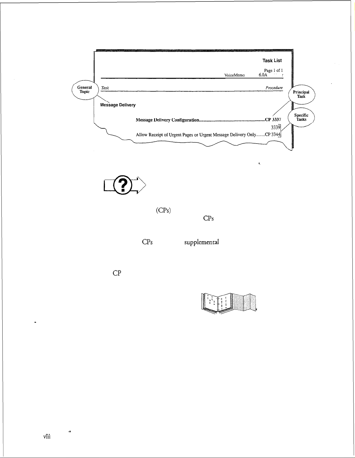
desired task (and procedure) quickly. The following example shows how a task list is
organized:
Each task is described in more detail in a procedure. For example, if
VoiceMemo
(CCTs),
Phase I and Phase II Installation and
responsible
firinciples.
They
vii
Page 7
About This Manual
VoiceMemo Release 6.OA and later
Procedures
Allow Mailbox OwnerstoControl Message
Delivery . . . . . . . . . . . . . . . . . . . . . . . . . . . . CP
m
Procedures follow the Task List of each reference chapter. Follow the steps in
Centigram Procedures
structured so that technicians can use the
step-by-step instructions.
When necessary,
procedures, other manuals, tables, and menu maps. These references are found in
the procedures’ reference columns.
Each
CL?
is numbered for document identification and referencing. Numbering does
not indicate a sequence of performance.
(G’s)
CPs
refer you to
to accomplish the desired tasks. The procedures are
CPs
as a simple checklist if desired, or as
supplementd
information such as additional
Menu Maps and Other Navigation Aids
Most of the documents in the new Centigram document library have menu maps or
a “road map” procedure. You can refer to these document navigation aids at any
point to help you reach a menu or show you which task to perform next. The List of
Centigram Procedures at the back of the manual lists all of the procedures in the
manual and tells you where to find them. It also tells you how they are related to
each other. And don’t overlook the index; it is the fastest way to find all references to
a specific topic.
. . .
Vlll
Page 8
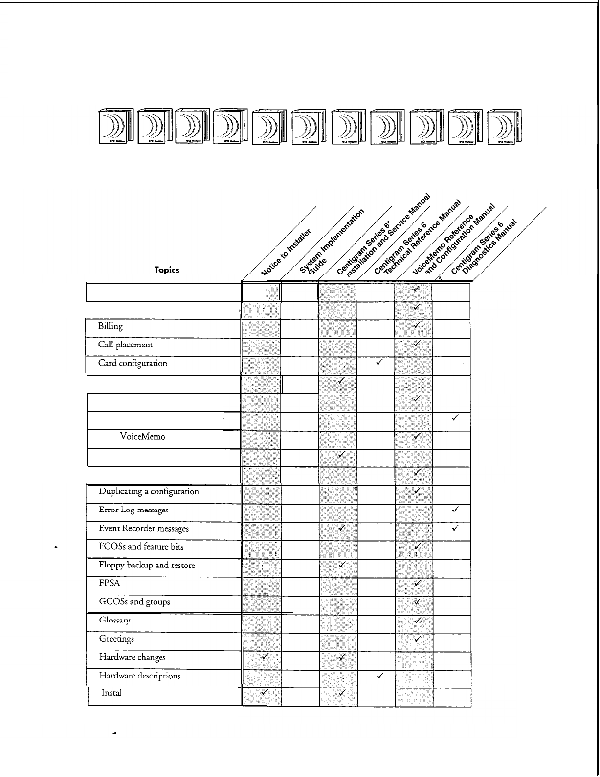
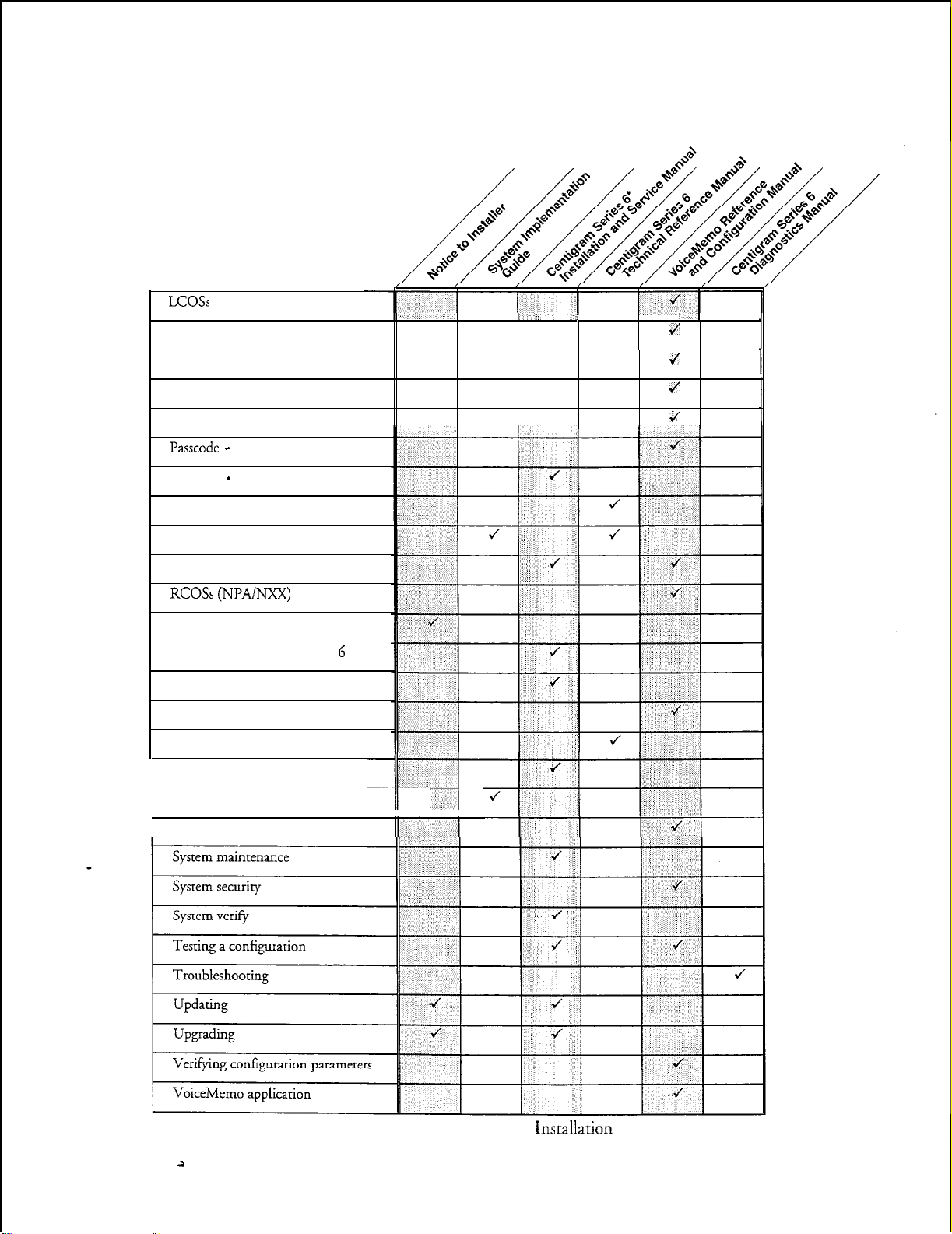
Which Document Do I Use?
Topics listed below are described in the Centigram documents indicated. This table
lists documents for the base hardware and software only, not optional features.
Activating an inactive configuration
Administration by Phone
About This Manual
Card replacement
Defining a line group
Diagnostics
DID
VoiceMemo
Disk replacement
Distribution lists
application
Installation procedures
I-~
ix
Page 9
About This Manual
LCOSs
and limits
Mailboxes
Topics (continued)
i
J
Message delivery
Message waiting lights
Paging
Passcode -
Password - console
Phoneline exceptions
Power information
Prompts
RCOSs (NPADJXX)
Release Notes
Repairing a Centigram Series 6 server
Replacing a Centigram Series 6 server
Reports
Resource Manager
Service procedures
1 Site preparation
System administration
mailbox
J
4
4
II -1
*Includes: Model 70, Model 1
il
X
20, and Model 640
Pnsmllation
and Service Manuals.
Page 10

What If Information Is Missing?
If the information you need is not yet available in the documents listed above, go to
these documents:
0
Release Notes
0
Other existing documents, as applicable
for
VoiceMemo
So&are
How Do I Obtain the Documents I Need?
To obtain other Centigram documents, contact your local Centigram distributor.
Conventions Used in This Manual
About This Manual
Release 6 OA
The procedures in this manual use the following conventions to
enter configuration information and how information is displayed on the Series 6
server console:
Press
Enter
Enter Type the text shown, then press the Enter key. For example, “Enter
bold
Selecti
Press
the Enter
number is correct.”
“Return” or has a return arrow (J) on it.
the line number (l-24)” means type a number from 1 through 24,
and then press the
Words or characters in bold type indicate either a value to be
entered by you exactly as shown or, when used to indicate a variable
entry, describe the type of value to be supplied by you. See example
above.
What you select from
a displayed menu
/
(G) Current Group
key.
For example, “Press Enter if the current
On some keyboards, this key is labeled
Enter
key.
A displayed prompt
for information
/
describe
how you
Prompt: Enter a group number =
Response: Number of the line group (l-24) to be used for the application.
Note:
\
What you enter in
response to the prompt
Unless otherwise stated, press
Enter
after each response you enter.
xi
Page 11
About This Manual
Reader Advisories
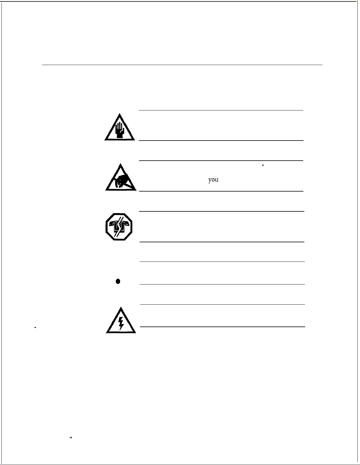
Reader advisories used in this manual are shown below.
Note:
Q
n
A
Information especially useful in relation to this procedure.
CAUTION!
Information that helps you prevent equipment or software
damage.
CAUTION!
Information that helps
(ESD) damage to the equipment.
WARNING!
Information that helps you prevent an interruption to
telecommunications traffic.
you
avoid electrostatic discharge
I
I
0
0
A
A
WARNING!
A hazard that can cause you personal injury.
DANGER!
Warns of a condition that could severely injure or kill you.
xii
Page 12

Before You Start
This manual assumes that you are familiar with using a console and keyboard. This
section describes how to use the Centigram Series 6 server effectively.
Console lips and Techniques
The tips and techniques offered in the following paragraphs can make configuration
entry sessions at the Centigram Series 6 server maintenance console more productive.
Viewing Menus
l
When you finish entering a value for a parameter, the server displays an
abbreviated form of the current menu, called the “short menu.” To view
the complete current menu when a short menu is displayed, just press
Enter.
l
To return to the Main Menu from any
configuration menu, press X (Exit), until the Main Menu appears.
Accepting Defaults
VoiceMemo
About This Manual
Z
application
l
To accept a default displayed in a
l
To accept a default displayed in a menu, no action is necessary.
prompt,
just press Enter.
Avoiding Automatic Exit
CAUTION!
The Centigram Series 6 server “times out” after 15 minutes.
This means that if you do not enter anything at the console for
15 minutes, the server automatically exits from the current
program. When this happens, all work that has not been saved
on the disk is lost.
To avoid being timed out and losing your work, follow these steps:
1.
When you need time to think, write down the name of the current menu.
2.
Exit to the (server) Main Menu.
3.
When you want to continue your work, enter the appropriate menu
options to regain your place.
Xl11
. .
Page 13
About This Manual
If you find that the Centigram Series 6
If your screen is blank, press any key to reactivate the screen and then continue with
these steps.
1.
Press any key to start the
Enter your user ID and password (if requested).
2.
Starting from the Main Menu, enter menu options to proceed to the menu
3.
from which the server timed out.
Reenter data as needed to regain lost work.
4.
senrer
login
has timed out, follow the steps below.
sequence.
Quitting an Entry Session
At any point during entry of offline or online parameters, you can quit.
discards all parameter entries you have made and leaves the
configuration
To quit from the
Select:
PTYWZ~~:
Response: Y to return to the
the way it was before you starred entering parameters.
VoiceMemo
(Q)
Quit -- Forget Changes
Quit and forget changes? (y/n) =
Configuration Offline or Online menu:
VoiceMemo
Configuration Main Menu.
VoiceMemo
Quitting
application
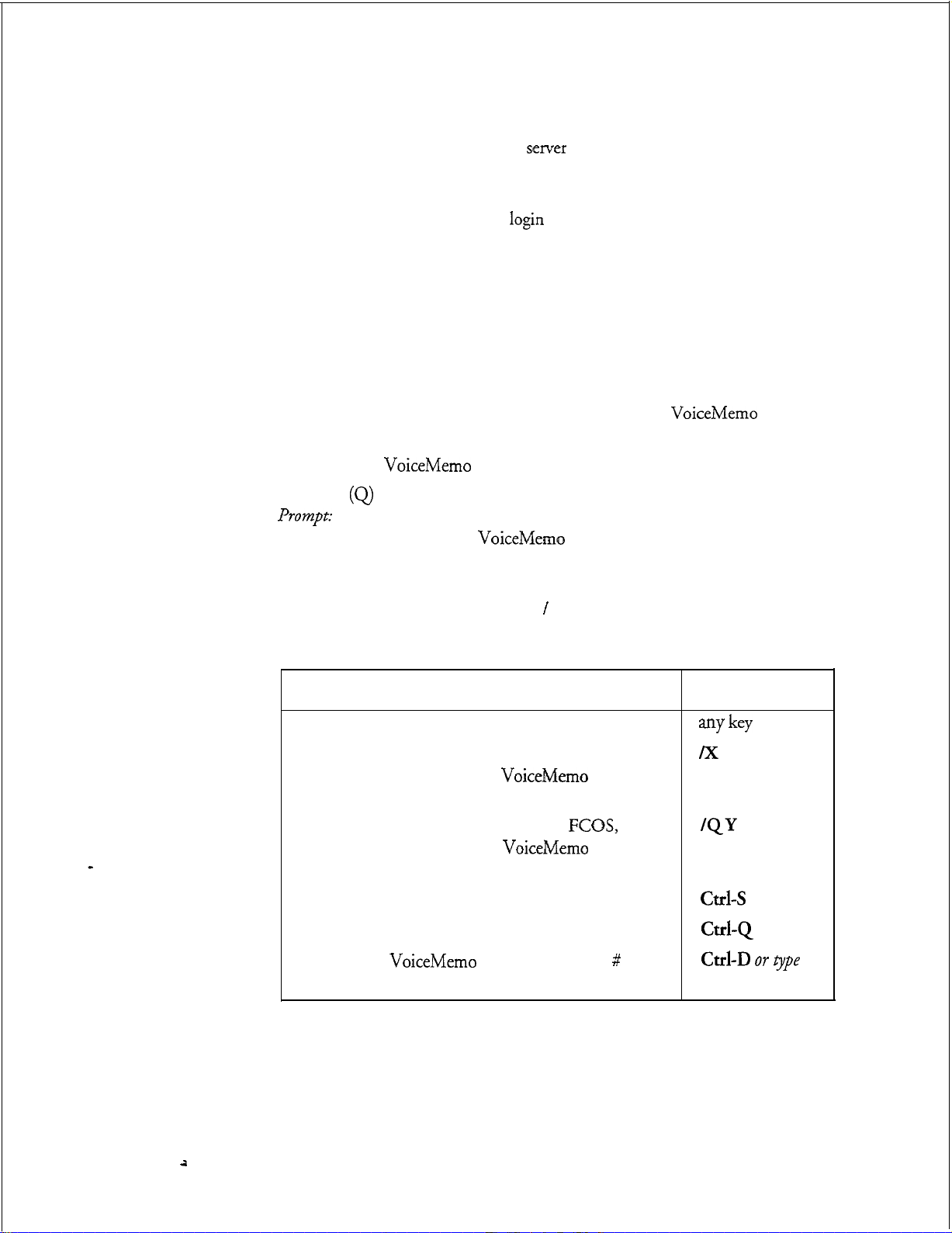
Shortcut Commands
You can use the Ctrl (Control) key or the l (slash) key while simultaneously pressing
another key to execute shortcut commands at an Centigram Series 6 server
maintenance console.
To do this...
Activate a timed-out console.
From the offline or online menus, or FCOS, LCOS,
GCOS menus, return to the
Configuration Menu and save any entries.
From the offline or online menus, or
GCOS menus, return to the
Configuration Menu without saving any entries.
Stop scrolling a displayed report.
Resume scrolling a displayed report.
Return to the
prompt is displayed.
VoiceMemo
VoiceMemo
FCOS,
VoiceMemo
application when
a # or $
LCOS,
Type...
my key
/X
QY
Ctrl-s
Cd-Q
Cd-D OY
exit
t3/pe
xiv
a
Page 14
Preparing for Hardware Installation
Before you begin to install any Model 70 hardware, read the following warnings.
WARNING!
About This Manual
0
0
I
0
0
5
AA
An equipment grounding conductor that is not smaller in size
than the ungrounded branch-circuit supply conductors must
be installed as part of the circuit that supplies the product or
system.
acceptable.
grounding conductors must have a continuous outer finish
that is either green, or green with one or more yellow strips.
The equipment grounding conductor is to be
ground at the service equipment.
WARNING!
The attachment plug receptacles in the vicinity of the product
or system must be of a grounding type and the equipment
grounding conductor serving these receptacles must be
connected to earth ground at the service equipment.
DANGER!
Never install telephone wiring during a lighting storm.
Never install telephone jacks in wet locations unless the jack is
specifically designed for wet locations.
Never touch uninsulated telephone wires or terminals unless
the telephone lines has been disconnected at the network
interface.
Use caution when installing or modifying telephone lines.
Bare, covered or insulated grounding conductors are
Individually covered or insulated equipment
s.connected
to
Page 15

About This Manual
Protecting Your Equipment From Damage
CAUTION!
u
a
If you follow these simple instructions, you
trouble, down-time, and customer dissatisfaction:
l
l
0
Many of the Model 70 components are easily damaged by
electrostatic discharge (ESD) or rough handling: line cards,
CPU cards, and hard disks are particularly susceptible to
damage. Unless instructed otherwise, observe the precautions
listed below and in individual sections during the handling of all
components.
will
Wear a grounded wrist strap
protects the components from electrostatic discharges (ESD).
Do an orderly shutdown of
to Cl? 6268, “Shut Down a System,” for instructions.
Removing or installing a component
severely damage both the component and its associated circuitry.
Always:
-
Wait 60 seconds after
should stop spinning and be quiet.
whi!e
handling components. Doing so
YOLU
server before turning its power off. Refer
YOLK
turn the server power off. The hard disk
reduce the risk of equipment
. .
whiIe
the server power is on can
-
If you need to set switches or jumpers on a circuit card, first place
the card on an anti-static mat. If such mat is not readily available,
use the card’s anti-static bag as a temporary mat. If neither a mat
nor a bag is available, do not work on the component until you
have obtained one.
-
s
Store circuit cards and other components in anti-static bags and
their original shipping boxes.
Page 16
1 Product Description
Introduction
This chapter provides a high level description of the Centigram Series 6
Communications Server Model 70 hardware and software functions, features, and
components.
Expanded discussions of some of the topics in this chapter are found in other
chapters of this manual. Additional information is also located in the
Reference and
Manual.
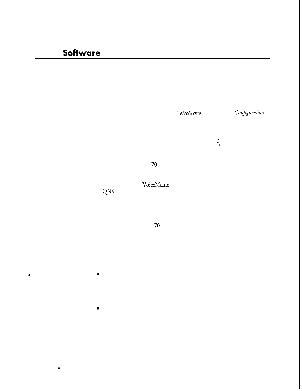
Model 70 Overview
The Model 70 is based on a standard desktop PC cabinet featuring seven available
ISA slots, a 200-watt AC power supply, a 486-66 MHz CPU, an IDE hard disk, a
3.5-inch
bus, and a modular design for quick and easy component maintenance. This server
can accommodate up to seven analog or digital adapter cards with a maximum of 30
ports (24 ports analog/30 ports digital) and up to two 500 MB IDE drives for a
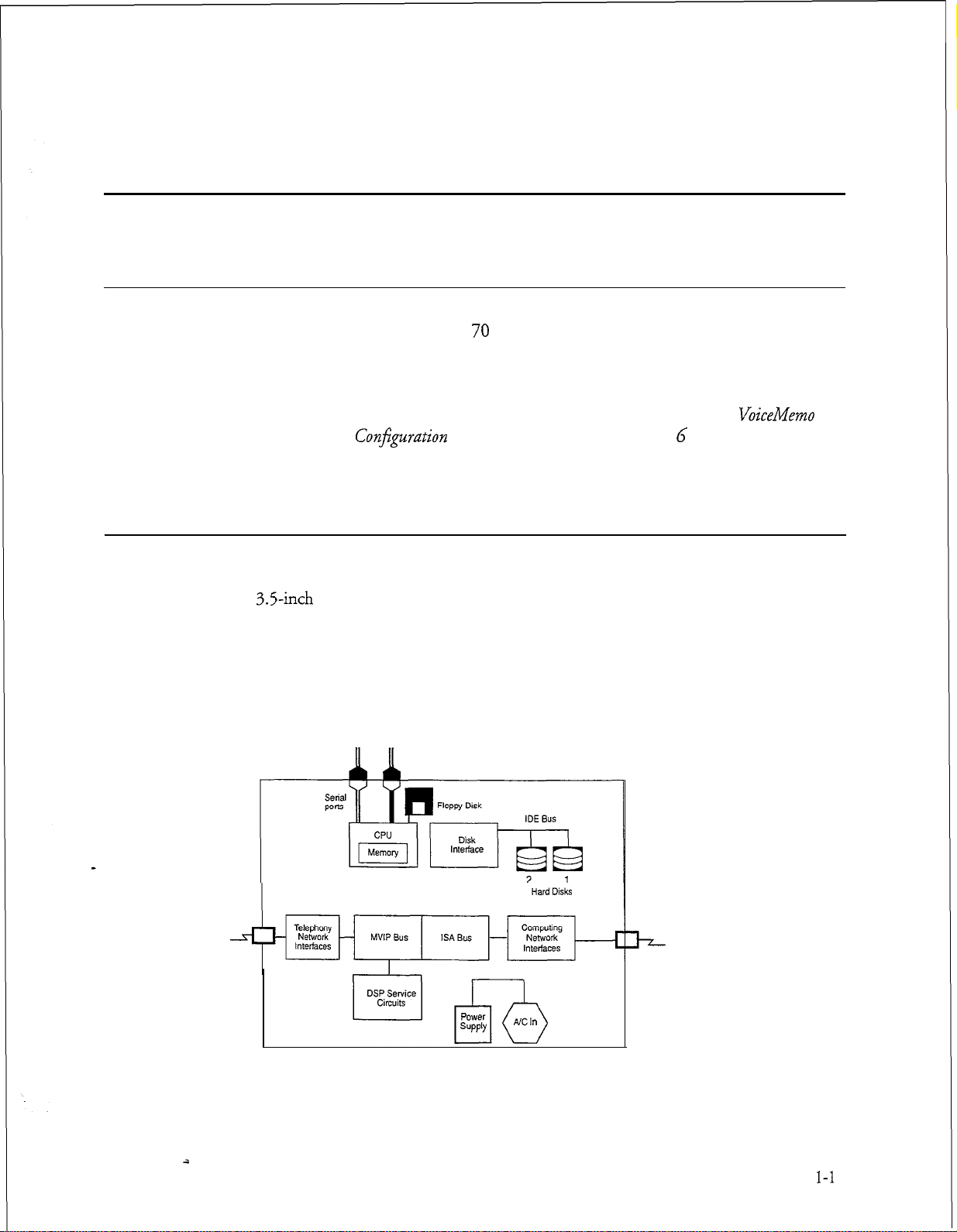
maximum redundant speech storage capacity of 55 hours. (Figure l-l shows the
Model 70 block diagram.)
It also provides general server specifications.
Conjguration
floppy disk drive, a special Multi-Vendor Integration Protocol (MVIP)
Manual and the Centigram Series G Technical Reference
VoiceMemo
Figure l-1
POW?r
SUPPlY
YYzb
Model 70 Block Diagram
NC
In
I-1
Page 17
Product Description
As the block diagram shows, the Model 70 is a PC-like server containing a CPU,
serial port, floppy disk, mass storage, and ISA expansion slots. Three types of ISA
adapter cards can be inserted into the expansion slots: telephony interface cards
(analog and digital interface cards), telephony service cards (Fax), and computer
interface cards (Serial, Ethernet). The telephony interface cards and the telephony
service cards can also be linked to the
h4VIP
bus, which is a special ribbon cable
linking the adapter cards together and allowing them to share resources.
There are two general categories of mailboxes that are available in the servers at
installation: standard (user/owner) mailboxes and special applications mailboxes. All
mailboxes can be
passcode
protected.
Classes of service are assigned to each mailbox. The Features Class of Service
(FCOS), Limits Class of Service (LCOS), and Group Class of Service (GCOS)
determine what a mailbox owner’s options are and how the
m&lboxes
function in
relation to one another and the server. The Network Class of Service (NCOS),
Restriction Class of Service (RCOS),
and Tenant Class of Service (TCOS) are
related to optional features.
Standard Model 70 features include voice messaging, audible tone message waiting
signals, and notification services.
letters instead of numbers for commands; for example,
The user interface consists of mnemonic (using
“I”’
to play a message) and
single-digit prompts, and an online user tutorial.
The following optional features are also available with the Model 70:
OneView,
Wakeup, Integrations, MESA-Net, and
Cut-Through Paging,
CallAgent,
AMIS
MESA Forms, Receptionist II, Auto
Analog. Additionally, specialty cards
FaxMemo,
can also be installed in the Model 70, such as a Fax card, Smartcard, Ethernet Card,
Serial
16/32
card, and others.
You can perform system administration and maintenance tasks either on-site or
remotely via telephone. A VT1 00 compatible terminal is required to perform
installation and maintenance, and an outboard modem with cables is required for
remote administration. (The
VT1
00 does not support full screen mode.) In
addition to adds and changes, maintenance and restore functions and system reports
are available to the system administrator.
Centigram’s
VoiceMemo
Release 6.0 is installed. To provide features, the Model 70
uses QNX , a real-time, multi-tasking operating system to control server resources.
The Model 70 supports the Audio Messaging Interchange Specification
(AMIS)
standard and can be configured to deliver to mailboxes on other vendors’ systems.
l-2
-ii
Page 18

Capacities and Expansions
Model 70
Maximum configuration for the Model 70 includes:
l
7 available line/specialty card slots
l
VoiceMemo
ports (24 analog/30 digital)
Product Description
l MI55 IDE hard disk
18.5Kbps,
l
Multiple, redundant hard disks (2 IDE disks
l
User/system prompts in four languages
l
Specialty cards: Fax card,
or 40 hours @ 24 Kbps
-
2,730 mailboxes; 55 hours of message storage
Smartcard,
Serial
maximur$
16/32
card, and Ethernet card
@
1-3
Page 19
Product Description
Model 70 General Server Specifications
Safety Compliance
This equipment meets or exceeds requirements for safety in the US (UL 1950 1st
Edition), Canada (CSA
FCC Regulatory Compliance
This equipment meets or exceeds requirements for EM1 and telephone
interconnectability standards in the US.
Physical Specifications
950),
and Europe (TW to EN60950, IEC 950).
Height (with feet installed)
Width
Depth
Weight
Server Environment
Temperature
Humidity
Altitude
BTUs
Noise at operator position
ESD
AC power
6.25 inches (15.92 cm)
16.35 inches (41.65 cm)
16.50 inches (42.67 cm)
21
pounds (9.5 kg)
Operating: 50 - 95 “F (10 - 35 “C)
Nonoperating: 40 - 158 “F (8 - 70 “C)
Operating: 85% at 95 “F (35 “C)
Nonoperating: 95% at 95 “F (35 “C)
Operating: to 10,000 ft (3,000 m)
Nonoperating: to 50,000 ft (15,240 m)
1700
41 dB
maximum with peripherals
15 kilovolts
100 - 120 volts AC, 50 - 60 Hz. 200
Watt
200 - 240 volts AC, 50 - 60 Hz, 200
Watt
idle
1-4
a
Page 20

Major Hardware Components
The Model 70 consists of a standard desktop PC cabinet featuring seven available
ISA slots, two peripheral bays, a 200-watt power supply, a 486-66 MHz CPU, an
IDE hard disk, a
component maintenance. It also features a special Multi-Vendor Integration
Protocol (MVIP) ribb
switch to any shared resource within the module level. The server backplane can
accommodate up to seven analog or digital adapter cards that total between 4 and 30
ports (24 ports analog130 ports digital). Both analog and digital cards can be mixed
in the same server. The server also accommodates up to two IDE hard disks for a
maximum redundant speech storage capacity of 55 hours. See Figures l-2 through
l-4 for details.
All major hardware components are replaceable and are referred to as field
replaceable units
includes the following major hardware components:
3.5-inch
floppy disk drive, and a modular design for quick and easy
on cable bus that connects all line cards, allowing them to
(FRUs).
The Model 70 standard configuration upon shipment
Product Description
Cabinet
l Cabinet
l Hard Disk
l
Floppy Disk Drive
l Line Cards
A
VT1
00 compatible terminal (administrative console) is required for system
administration and installation. For remote administration, an external modem is
also required.
The Model 70 is housed in a standard PC cabinet. The housing and its major parts,
listed below, are considered one component.
l
An ISA-compatible motherboard with a passive backplane, which supports
up to seven 16-bit ISA/AT compatible cards (line cards, fax cards,
Smartcard, Serial
l
A 200-watt switchable power supply, which provides power for outboard
16/32
card, or an Ethernet card).
resources, add-in boards, hard disk, and floppy disk drive. The power
supply can operate at 120 volts AC or 240 volts AC.
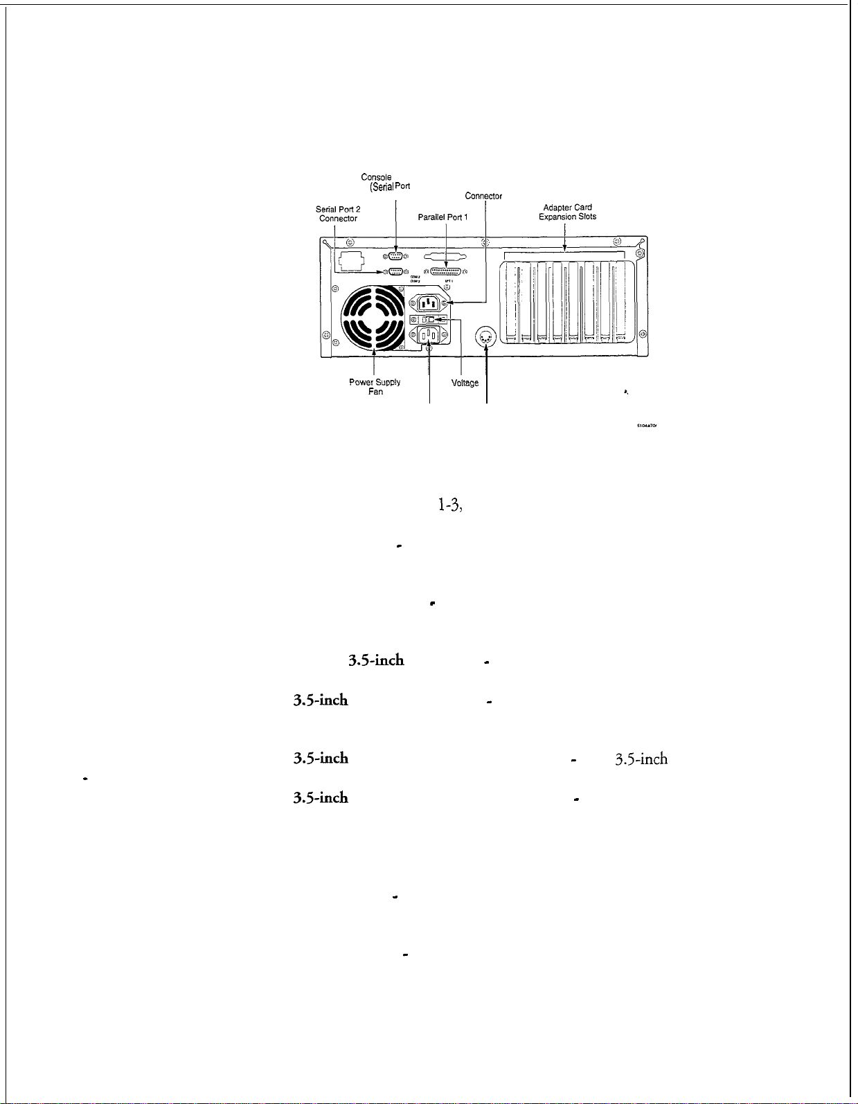
Figure l-2 shows the details of the rear panel. The rear panel includes the following
connectors:
l
Console Port (Serial Port 1) - provides connection to console
l-5
Page 21

Product Description
l
Serial Port 2 - (RS-232C connector) provides connection to the remote
administration/maintenance modem and optional printer
l
Parallel
l
AC Output Power Connector - provides connection to a peripheral
l
Adapter Card Expansion Slots (7) - provide external connection to seven
Port
1 - not supported
adapter cards . Although there are eight slot openings at the rear panel, the
slop opening closest to the power supply has no corresponding connector
to the motherboard.
l
Keyboard Connector - not supported
l
Voltage Switch - selects operating voltage:
l
AC Input Power Connector - provides connection to a
120
volt’. (default) or
240
+W/12V
supply provided by user
volt
power
l
Power Supply Fan - provides cooling for the cabinet
Page 22
Console
(Serial Port
Connector
1) AC Output Power
Product Description
COllWXtCN
Power supply
Fan
AC Input Power Keyboard Connector
Connector (Not Supported)
Figure l-2
Model 70 Rear Panel Connectors
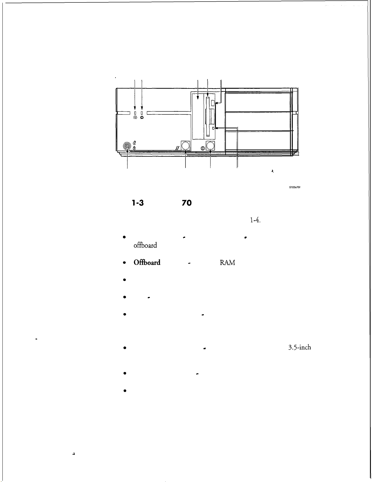
The front panel, shown in Figure
l
HDD LED (Red) - indicates the state of the hard disk and lights when the
hard disk is accessed
l Power LED (G
reen)- indicates the power status and lights when the
server power is on
l
l
Bay for
3.5inch
35inch
Hard Disk - covered with filter panel and EM1 shield
Floppy Disk Drive - used an interface to install, reconfigure,
backup, and update the server software
l
3.5inch
Floppy Disk Drive Eject Button - ejects
Voltage
Switch
1-3,
includes the following controls and indicators:
3.5inch
diskettes
l
3.5inch
Floppy Disk Drive LED (Green) - indicates the state of the
floppy disk drive and lights when the floppy drive is accessed
l
Power Button- turns the server on and off
l
Reset Button - initiates a warm boot, which resets the server without
turning off the power supply
l
Keyboard Lock - not supported
l-7
Page 23
Product
Description
HDD LED Power LED
3.5inch Floppy
Disk Drive
Bay for 3.5-inch
Hard Disk
Floppy disk Drive
Eject Button
Keyboard Lock
(Not Supported)
Figure
l-3
Reset
Button
Model 70 Front Panel Controls and Indicators
Power
Button
Floppy Disk
Drive LED
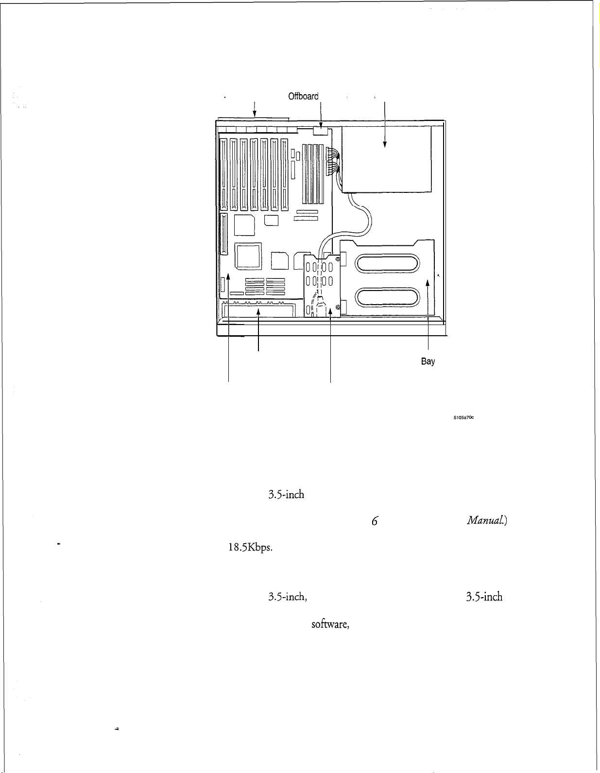
The internal layout of the cabinet is shown in Figure
Expansion Slots - Slots are numbered 0 - 6. Slot 6 is closest to the
offboard
Of%oard
battery.
Battery - for CMOS
FUM
Power Supply
Bay - Not used
Front Bezel Assembly - Contains reset button, power on/off button, drive
activity lights, power on light and speaker (between bezel and metal
chassis)
,,
l-4.
It includes the following:
l-8
Bay and Carrier Disks - Carrier contains hard disk and
3.5-inch
floppy
disk drive
Auxiliary Front Fan - and motherboard guides
Motherboard
2
Page 24
Product Description
Expansion Slots
Front Fan and
Motherboard Guides Assembly
Offboard
Battery Power Supply
Front Bezel
Bay
(Not Supported)
Figure l-4
Hard Disk
The Model 70 features a
system, speech, names, greetings, prompts, messages, and applications. (For specific
hard disk specifications, see the
server can accommodate up to two disks for a maximum of 55 storage hours, with
redundancy, at
Floppy Disk Drive
The Model 70 features a
double sided, double density diskettes. The floppy disk drive is used to install,
reconfigure, and update the server
and increase the memory storage capacity of the hard disk.
Motherboard
Model 70 Internal Components
18.5Kbps.
3.5-inch
3.5-inch,
Bay and Carrier for
Hard Disk and Floppy
Disk Drive
IDE hard disk (M155) that stores the operating
Centigram Series G
1.44 MB floppy disk drive that uses
so&ware,
backup mailbox and account data files,
Technical
Reference
ManuaZ.)
3.5-inch
This
1-9
Page 25

Product Description
Line Cards
Line cards are the primary interface between the Model 70 and the telephone
network. These cards control all incoming calls, including fax messages. All line
cards support the Multi-Vendor Integration Protocol (MVIP), which enables the
Series 6 server to interface with a wide range of third-party telephony cards.
Line cards are available in four or eight ports configurations, and are full-size AT
cards that plug into empty slots on the Model 70 cabinet’s backplane. There are two
general types of line cards offered: analog and digital. The analog line cards include
(4/8
ports) Loop Start, Ground Start Trunk, Direct Inward Dialing Trunk, and
E & M Trunk. The digital cards offered are Tl (24 ports) Loop Start, Ground Start
Trunk, Direct Inward Dialing Trunk, and E & M Trunk and El (30 ports) An
external -48 volt power supply is also required when using DID, E & M, or Ground
Start line cards. For detailed line card information, see the
Ceatigram
Series
G
Technical Reference Manual.
The line cards have the following features:
Specialty Cards
The Model 70 can also accommodate specialty cards that support computer, fax, and
LAN services (such as, Fax cards, Smartcards, Ethernet cards, and Serial
cards).
l
Speech digitization (analog-to-digital and digital-to-analog) and
compression
l
Line signaling and supervision
l DTMF , progress tone detection, and synthesis
l
Control and speech buffer memory for each of two channels, and program
memory
l
Multi-Vendor Integration Protocol
&NIP)
support
16/32
l-10
a
Page 26
Product Description
Fax Card
Fax cards handle incoming fax messages and support other telephone interfaces.
When the incoming fax tone is emitted, the fax card performs a “handshake” with
the fax machine that is sending the tone and processes the incoming fax. The Fax
card sends the fax to the hard disk where it is stored for later retrieval or distribution
by the user. For detailed Fax card information, see the Centigram
Reference Manual
and the
VoiceMemo FaxMemo Manual.
Series G
Technical
Smartcard
Smartcards provide multiple, simultaneous serial connections required for
applications such as PBX integration, host computer communication, and
Net networking. This card is compatible with EIA RS 232-C,
V.28 asynchronous communications standards.
Smartcards feature two, four, or eight ports and are full-size AT cards that plug into
empty slots on the Model 70 cabinet’s backplane. For detailed Smartcard
information,
Smartcard Manual.
see
the
Centigram Series 6 Technical Reference Manual
CCITT
and the
MESA-
V.24, and
Serial
Serial
throughput, such as sixteen channels through an external adapter box. For detailed
Serial 16132 card information, see the
16/32
16/32
Card
cards are replacement cards for Smartcards that provide faster
Centigram Series G Technical Reference Manual.
Ethernet Cards
Ethernet cards provide special local area networking capabilities. For detailed
Ethernet card information, see the Centigram
Series G Technical Reference Manual.
1-11
Page 27
Product Description
Major
Sokware
This section provides an overview of available user and server features and special
applications. Depending on your specific server configuration, the Model 70 you are
working with will include some or all of the features discussed in this section.
Software, including support for some optional features, is loaded in the Model 70
when shipped. Additional hardware is required to implement some optional
features.
For more detailed information, refer to the
Components
Manual.
Series 6 Communication Server
The Model 70 is one of the Series 6 Communication servers. Tt is a modular, open,
standards-based communication server that allows users, to make, send, receive, and
answer voice and fax messages from a single mailbox 24 hours a day, using a
pushbutton phone. The Model 70 is compatible with virtually every PBX and
Central Office Switch.
The server is shipped with
uses the
QNX
operating system from QNX Software.
VoiceMemo
VoiceMemo
Software Release 6.0. The Series 6 server
Reference and
ConJZguration
Mailbox User Features
Voice Mail/Messaging
The basic function of the Model 70 is message taking and retrieval. The mailbox
user can receive, review, save, delete, and reply to or send messages.
Several delivery options are available to users:
l
Marking a message as urgent
*
Making a message confidential (so that it cannot be passed on to another
user)
l
Specifying message delivery dates (future delivery)
@
Requesting a return receipt (verification that the message was listened to)
Customization
Users can customize mailboxes. This customization includes greetings, distribution
lists, fax delivery, and reminder calls.
1-12
2
Page 28
Product Description
Distribution lists
A distribution list allows a mailbox user to send the same message to several other
users simultaneously. Mailbox user distribution lists are established over the
telephone. Each list is assigned an individual distribution list number.
Two types of lists are available: mailbox user distribution lists, which are accessible
only by the mailbox owner; and master, or system distribution lists, which are
established by the system administrator and accessible by all users of a line group.
The ability to create, access, or be part of a distribution is determined through class
of service assignments.
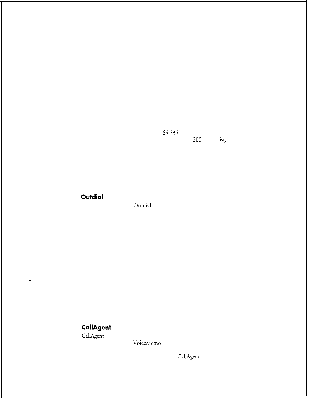
A distribution list can contain up to
of 200 personal distribution lists per mailbox and
can be nested, enabling one list to contain other lists.
65,535
members. The server allows a maximum
200
master
lisp.
Distribution lists
Message Waiting
This feature provides a “stutter” dial tone or flashing light indication at the user’s
phone to signal that a new message has arrived. This audio indication is only
available on the telephone number associated with the user mailbox.
Outdial Notification
There are two types of
Paging notification uses a radio pager to let the mailbox user know in real-time that
there is a message waiting. If the pager is a voice pager, the server delivers the first 30
seconds of the voice message. (Message length is dependent on the pager company.)
It can also send customized alphanumeric messages.
The user can customize this feature so that the server calls up to two primary and two
alternative pager numbers. Notification can be given at specified intervals for all
messages or set to notify only when urgent messages are received.
Outdial
Notification: Paging and Message Delivery.
I
Optional Features
Message Delivery provides notification to a telephone number not associated with a
pager. The Model 70 calls the designated telephone number at specified intervals,
announce the number of messages waiting for review, and ask the user to log into
their mailbox.
CallAgent
CallAgent
conjunction with your
attendant and call processing applications, letting you control the time, destination
and method of each call processing event.
adds call processing capabilities to your Model 70 while working in
VoiceMemo
software. It allows you to create automated
CallAgent
gives you the option of
1-13
Page 29
Product Description
arranging the presentation of what callers hear and where callers go within the server.
It can be programmed or changed over the telephone using simple menu-driven
pushbutton commands.
Auto Wakeup
The server allows the mailbox user to schedule wakeup or reminder calls. These calls
can be scheduled for and made from the server any time, any day and anywhere.
Each call can be directed to a specific telephone number and can occur multiple
times at specified intervals.
Cut-Through Paging
Cut-Through paging sends the actual call-back number rather than the mailbox
number to the mailbox user’s pager.
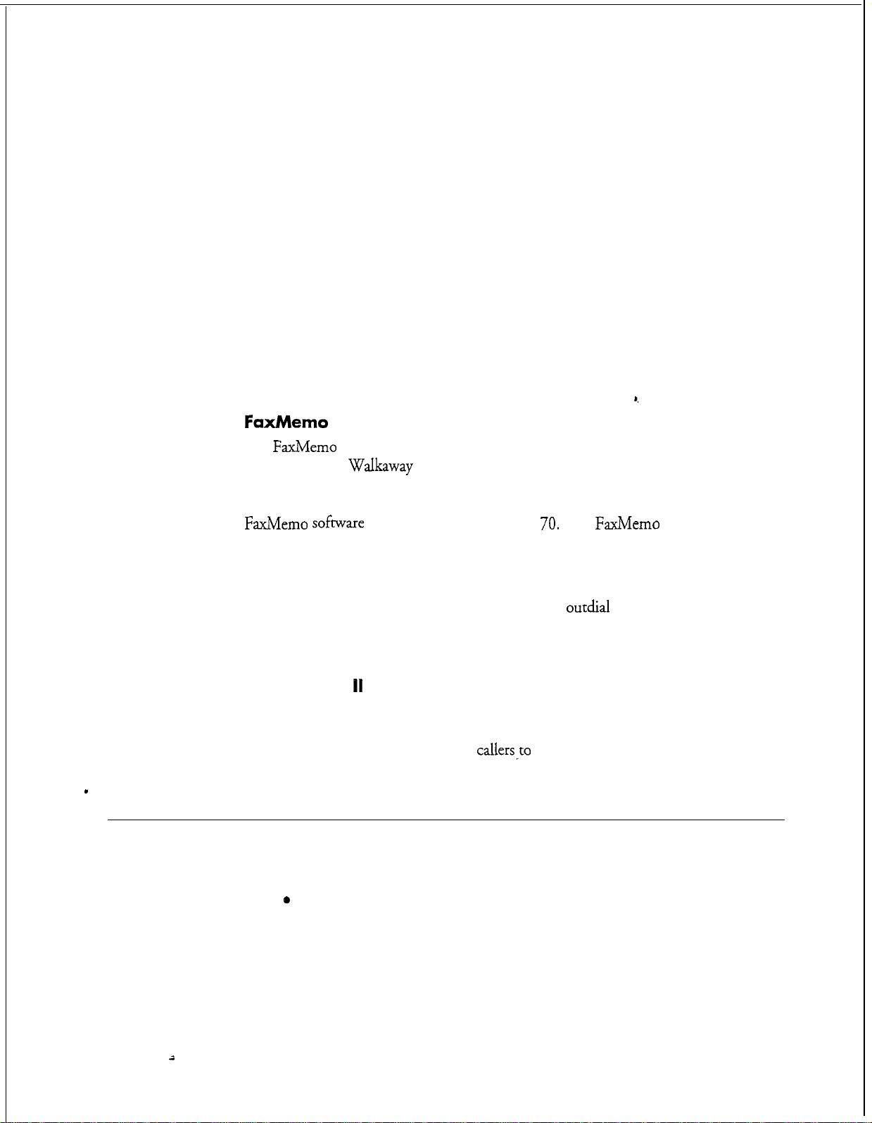
FaxMemo
The
FaxMemo
Publishing, and
answer, voice annotate, and distribute fax messages. It also provides automatic
and/or scheduled delivery via facsimile (download to any fax machine). The
FaxMemo sofmare
purchased separately for the feature to work.
application includes Fax Mail, Fax Broadcast, Guaranteed Fax, Fax
Walkaway
Fax..
is supplied with the Model
These applications allow users to send, receive,
70.
The
FaxMemo
card must be
Special Pager Terminal Protocol Paging
Special pager terminal protocol paging customizes
with pager systems (TNPP protocol) used by hospitals and other organizations with
private, or highly specialized, pager networks.
Receptionist
With this feature, the server answers incoming phone calls and asks callers to enter
the extension number or name of the party they wish to call. Once the information
has been entered, the server transfers
I
Outside Caller Features
All outside caller features can be enabled/disabled from the server console. Callers who
leave messages can:
0
Replay and rerecord their messages
l
Make their messages urgent, placing them in front of the normal message
queue
11
callersPto
outdial
notification to interact
the desired extension.
1-14
l
Leave messages in additional mailboxes on the server
2
Page 30
l
System Features
Distribution lists (also see Mailbox User Features)
A distribution list allows a mailbox user to send the same message to several other
users simultaneously. Mailbox user distribution lists are established over the
telephone. Each list is assigned an individual distribution list number.
integrations
Integrations establish the connection between the telephone switch and the Model
70. They provide call information for direct and forwarded calls and message
waiting signals for the user.
In-band DTMF integration is standard and allows the switching system and Model
70 to communicate by exchanging tones in the voice frequency band.
Product Description
Be transferred to the operaror or any other extension on the switch
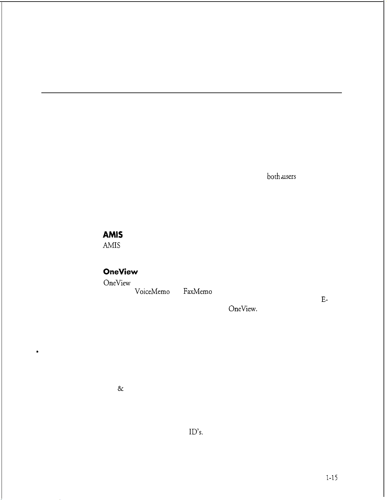
Integrations are transparent to
both*users
and callers.
Optional System Features
AMIS Analog
AMIS
Analog is a system networking application that enables the Model 70 to
communicate with other vendors’ voice processing systems.
OneView
OneView
Centigram
receive fax messages on your PC, and to exchange messages using your current
mail application by launching it from within
your voice and fax messages at a glance, prioritize them, and send and receive
messages that combine voice mail and faxes.
is a multimedia desktop messaging program that works with the
VoiceMemo
Functional System Partition Administration (FPSA)
This feature adds a much higher level of security to Series 6 server administration for
both Customer Premise Equipment (CPE) customers and service providers. FPSA is
particularly useful to telephone companies, service providers, and large CPE
customers who want to limit access to operations, administration, and maintenance
(OA & M) functions on a departmental or individual basis. In addition, FPSA
offloads or resells certain administrative functions to restricted groups within your
organizations or within your customer base. FPSA adds security in five ways. First,
it can be activated only by a special diskette, which will be shipped upon request.
Second, FPSA controls access to all parts of the server (administration menus or
QNX) by passwords and user
commands. Fourth, superusers can force system administrators to change their
and
FaxMemo
ID’s.
Third, you can control who has access to batch
applications. It allows you to send and
OneView.
It also allows
you to
E-
view all
l-15
Page 31

Product Description
passcodes every number of days.
is turned on) every time an administrator enters the server.
Fifth, FPSA provides an audit trail (if the audit trail
Automated or Video Dispatch
This feature enables you to establish mailboxes with specialized distribution lists for
dispatchers and field service representatives. Dispatched message activity can be
displayed on a terminal. This application is used by customers with dispatch
operations units to increase productivity and reduce dispatch costs.
Call Detail Recorder (CDR)
CDR tracks server activity for billing purposes.
number of messages received, faxes delivered, and
or system level. CDR enables you to bill mailbox users, cost centers, or specific
accounts directly.
It records call information, such as
outdial
notifications, on a mailbox
z
Configurable Data link and Electronic Set Emulation
Integrations
Direct Data Link enables the Model 70 to use a separate data communications
circuit to receive call processing information from the PBX or CO. With Electronic
Set Emulation, the Model 70 acts as an electronic telephone set to the PBX. Both
are optional integration features.
Foreign language Prompts
The Model 70 plays all prompts in a maximum of four languages. Some of the
available languages are English, French, French hotel, Spanish, German, Portuguese,
Japanese, and Korean.
MESA-Net
MESA-Net is a digital networking application that enables up to 1500 remotely
located Series 6 servers to communicate with each other over 16 simultaneously
operating digital links.
Administered
AMIS
Classes of Service
Classes of service define the features and capabilities of mailboxes. Six distinct
classes of service categories can be programmed and assigned independently of one
another. Classes of service can be used in combination to build multiple tiers of
service offerings or privileges. More information about classes of service can be
found in the
VoiceMemo
(Some of the 1500 remote Series 6 servers must be shared if
is also being used.)
Reference and
Conjgurati.on
Manual.
Page 32

Feature Class of Service (FCOS)
An
FCOS determines what voice mail capabilities a mailbox user has and how each
call is processed. Each feature is called a feature bit. Over 200 features bits are
available. The server allows a maximum of 640
Each mailbox must be assigned an FCOS.
limits Class of Service (LCOS)
The LCOS defines all of the time and storage parameters of a mailbox by restricting
message, greeting, and outdialing digit lengths. This class of service is used to
control server resources. Up to 640
different categories of parameters. Each mailbox must be assigned an LCOS.
LCOSs
Product
FCOSs,
can be programmed to quantify
or combinations of features.
Description
Group Class of Service (GCOS)
The GCOS defines the number of users any particular user can exchange messages
with. This class of service provides software partitioning at the mailbox level,
without requiring partitioning at the line group level.
Two types of groups can be configured: flexible, or bitmapped, GCOS, which
allows multiple groups to exchange messages; and closed, or
restricts message exchange to within the defined group of users.
Up to 64 bitmapped
Model 70. Each mailbox must be assigned a GCOS.
GCOSs
and 32,000 affinity
Network Class of Service (NCOS)
The NCOS works in conjunction with the MESA-Net digital networking feature.
is used to assign a user’s access and priority on a network that is set up to connect
multiple Series 6 servers.
Restriction Class of Service (RCOS)
The RCOS is a parameter assigned to mailboxes that limits what telephone number
can be outdialed. Limits are placed on the area codes or exchanges a mailbox can
outdial.
GCOSs
z
affinity,
can be assigned in the
GCOS, which
It
Tenant Class of Service (TCOS)
The TCOS is a mailbox option used with the SMDI integration. This feature
governs mailbox interaction between user communities.
1-17
Page 33

Producr Description
Special Application Mailboxes
You can configure special application mailboxes in the Model 70. Two special
application mailboxes are already preconfigured in the software, the administrator
and attendant mailboxes. You can create combinations of special application
mailboxes for special purposes. You can find more information about special
mailboxes in the
Administrator
VoiceMemo
Reference and
Confguration
Manual.
Attendant
Broadcast
Chain
The Administrator’s mailbox is included in the preconfigured
It belongs to the system administrator and has unique special privileges. These
privileges allow you to perform mailbox adds, changes, and deletes by telephone;
create master or system distribution lists; and record the company or system greeting.
The Attendant mailbox is also included in the preconfigured software installation.
This mailbox contains the “message of the day” greeting and a customized user
tutorial. It is also the mailbox that receives all unaddressed messages (where neither
an extension number nor a user name is entered by the caller).
Broadcast mailboxes allow both users and outside callers to record and send a single
message to multiple mailboxes. Voice and fax messages can be sent via the Broadcast
mailbox. Distribution lists are configured by either the system administrator or the
user. Each broadcast mailbox can send messages to up to 65,535 members.
Chain mailboxes allow callers to enter either the desired extension number, or the
name of the mailbox owner or mailbox number. Once the information has been
entered, callers are transferred to the appropriate mailbox or extension.
so&are
installation.
-
Greeting Only
Guest
4
1-18
Greeting Only mailboxes are used to provide information to callers, but do not allow
callers to leave a message. There are three types of greeting only mailboxes: voice
greeting, fax greeting, or voice and fax greeting.
A Guest mailbox is assigned on a temporary basis. It does not require an owner
name or
passcode
for access. This mailbox cannot save messages.
Page 34

Rotational
Rotational mailboxes allow constantly changing greetings, either by time and day
(period rotation) or with every call (index rotation).
Tree
Tree mailboxes route calls to preselected mailboxes when callers enter a single digit.
Callers hear a greeting which gives instructions on which single digit to enter to reach
the desired destination. Tree mailboxes can be configured to process callers with
rotary dialers.
Shared Extensions is a type of Tree mailbox which allows more than one individual
or telephone number to access the same mailbox. Discrete passcodes are assigned to
each partition within the mailbox to provide privacy for the
Optional Special Application Mailboxes
Guaranteed Fax
A Guaranteed Fax mailbox is associated with the
creates a “never busy” fax machine. If the fax machine is busy, the call can be
forwarded to the Guaranteed Fax mailbox, which will receive the fax. Once received,
the mailbox attempts delivery to the fax machine until it gets through. The
operation is transparent to the fax sender.
FaxMemo
Product Description
sharing
optional feature and
users.
Fax Publishing
With fax publishing, mailboxes can be configured to supplement prerecorded
outgoing messages with related hardcopy documents, such as product or company
information. This feature provides a convenient way to disseminate frequently
requested information to employees, customers, and outside callers.
Fax Store and Forward
This feature enables users to store and forward fax messages the same basic way they
store and forward voice messages.
to store important faxes and relay them to other related parties.
Fax Store and Forward provides an efficient way
MESA Forms
MESA Forms is a template, or voice forms, application. It allows callers to leave
messages in a way that simulates written information on paper forms, such as
questionnaires, requests for information, or schedules.
l-19
Page 35

Page 36

2 Installing New Systems
How To Use This Chapter
This chapter provides step-by-step procedures for installing a new Model 70.
Additional information is also located in the
Manual, Centigram Series G Technical Reference Manual, and the System
Implementation Guide.
V&&Memo
Reference and
Confguration
A task list and Centigram Procedures
located at the end of this chapter. The task list identifies two procedural levels of
CPs:
a high-level CP and a low-level Cl?. A high-level CP provides instructions on
how to do overall tasks, such as installing a server. A low-level CP provides
instructions on more specific tasks, such as how to install a line card.
Readers familiar with Centigram servers can use the
while readers new to Centigram servers can use
After gaining experience with this documentation, you can find your own innovative
way of using the task list.
provided below:
Using the Task list
Select from the task list the title of the task that you want to perform and note its
high-level CP number. Flip through the
correct CP number. Follow the instructions given in the CP.
A reference column in each CP contains pointers, when necessary, to supplemental
information such as another procedure, a technical reference in the Centigram Series
G
Technical Reference
included with this binder to find referenced supplemental information that is located
within this manual.
(CPs)
describing new server installations are
CPs
as a checklist if desired,
CPs
for step-by-step instructions.
One possible approach on how to use the task list is
CPs
in this chapter until you find the
Manual
another manual, or menu maps. Use the tabs
If you need to interrupt a CP and seek reference information, first mark the CP with
your bookmark or otherwise note down where you are in the CP. After you are
finished with the reference information, return to the CP and continue to execute the
steps where you left off.
2-1
Page 37

Installing New Systems
Site Selection and Preparation
The Model 70 is designed to work in a typical commercial environment. Physical
space requirements are nominal. The following information describes general site
selection and preparation details. For detailed information, refer to the
Implementation
Choose a site that is:
Guide.
Located near a grounded, three-pronged power outlet (for the United
States and Canada, this means a
AC or a NEMA 6 -
regions, please refer to the electrical codes of that region). Noise and surge
protection is required.
Clean and dust free
Well ventilated and away from heat sources, including direct sunlight
15R
outlet for 200 - 240 volt AC; for any other
NEMA 5 - 1.5R
$j~ern
outlet for 100 - 120 volt
Z
At least three feet from strong electromagnetic fields produced by electrical
devices (such as air conditioners, large fans, electric motors, radio and TV
transmitters, and high-frequency security devices)
Page 38

Before You Start
1.
2.
Installing New Systems
Set up an equipment log to record server model and serial numbers, the
server configuration and options found on the worksheets provided to you
by your system design engineer, and other information about the server
you might find helpful.
Check the power supply setting. The 200-watt power supply is integrated
into the server to provide power for all resources, drives, cards, and
peripherals. A switch on the back panel is used to set the power supply to
operate at 115 volts AC (in the range of
maximum current) or 230 volts AC (in the range of 200-240 volts AC; 4
amps maximum current). The switch is set at the factory for 115 volt AC
operation. To verify that your server has the correct setting, check the
input power selection switch on the rear chassis. See Figure 2-l for
details.
loo-120
volts AC; 6 amps
Figure 2-1
3.
Check the power cord. In some cases, the power cord supplied with the
Model 70 might not be compatible with the type of AC wall outlet in
your region. If your power cord is incompatible, you must obtain a
suitable power cord that meets the following criteria:
Power Supply Setting
2-3
Page 39

Installing New Systems
The cord must be rated for use at the AC voltage available, with a
current rating that is at least 125 percent of the current product
rating.
The connector at the end of the cord that plugs into the AC
outlet must be a grounding-type male plug and must show
certification by an agency acceptable in your region.
The connector at the product end must be an IEC type CEE-22
female connector.
The cord must be less than 14.8 feet (4.5 meters) long.
z
I
n
0
WARNING!
Do not attempt to modify or use the supplied AC
power cord if it is not the exact type required.
WARNING!
Do not attempt to install or remove any components
or peripherals while the Model 70 cover is removed
when the server is turned on. Hazardous voltage,
current, and energy levels are present in this product.
wall
2-4
4. You need a Phillips screwdriver
screwdriver. You should use an anti-static wrist strap and a conductive
foam pad when working on the server.
CAUTION!
Electrostatic discharge (ESD) can damage hard disks,
boards and other components. Wearing an antistatic wrist strap attached to a metal part of the server
chassis will reduce risk significantly.
5.
Be sure to do each procedure in the correct order
2
(~62
bit) and a medium flat-bladed
Page 40

Installing the Model 70
Installing New Systems
Each Model 70 is shipped
and software loaded). Regardless of configuration, the base server is shipped with the
components listed below. (Additional components might be needed, depending on
specific country requirements.)
l Model 70
l Modem
l Modem Cable
l Power Cable
Figure 2-2 illustrates the server components and basic installation procedure. To
install the Model 70, follow the steps shown in the Centigram Procedures (Cl’s)
listed in the Task List at the end of this section.
Ethernet or ArcNet
preconfigured
per specific customer order (all hardware
Switch
H
Telephone
Network
interface
A/C
In
NC 01 It
In
!I
Figure 2-2 Model 70 Components
2-5
Page 41

Installing New Systems
Customer Turnover
After you have completed the post installation audit checklist as described in the
System Implementation Guide, turn the account over to the group responsible for
ongoing maintenance and support.
Provide the customer with appropriate telephone numbers and escalation procedures.
Discuss outstanding items to be completed, review special applications, and
communicate areas of concern.
2-6
Page 42

Installing New Systems
Installation Task list
Page 1 of 1
VoiceMemo
Release
6.OA
and later
Procedure
Model 70 Installation
Check Installation Quality ........................................................................
Connect
Install
Install Modem ..........................................................................................
Install
Install
Run a System Information Report ............................................................
Run Verify With System Online ..............................................................
Test Basic Telephony Functions..
Note:
Telephone
the
Console.. ........................................................................................
PrinterI............................................................................................
Redundant Hard Disk ...................................................................
Procedures for building the customer database are in the
VoiceMemo Reference and Confguration Manual.
For additional information, refer to the Centigram Series
Technical Reference Manual,
Guide. For detailed information about optional features, refer to
the respective optional feature manual.
Updates to procedures and the Model 70 are issued to the field in
Centigram’s Notices to Installers. You should add them to this
guide, as appropriate.
..........................................................................
Lines
...................................................................
............................................................. CP 6201
and the
System Implementation
a? 6590
Cl? 6258
Cl? 626 1
CP
62
CP 6270
CP 6215
CP 6284
CP
1340
CP
7001
G
16
Page 43

Run a System Information Report
This procedure describes how to run a System Information Report. The System
Information report shows all the levels of software previously loaded in the server; the
type of floppy diskdrive installed; the hard disk serial number(s); and the number of
system hours, ports, and links in the server.
VoiceMemo Reference and
Conj&ration Manual.
VoiceMemo
To run additional reports, refer to the
Release
Page 1 of 2
6.OA
and later
FOR THE MODEL 120 AND MODEL 70
procedure may contain generic references to other multiple-module Centigram Series 6
products. In such cases, shaded areas indicate a difference in operations for the Model
120 and Model 70. The Model
module” servers. When asked for the number of the host or module, always enter “1” or
“a”.
This procedure applies to servers using either SCSI or IDE hard disks.
Step
1. Reach the Reports Menu.
2.
Run the System Information report.
Select:
Prompt:
(I) System Information
REPORT OUTPUT ROUTING
(C)
Console (screen)
(P) Console with pause
(1) Printer A
(F)
File...
(A) Append to file...
(X)
Exit (no report)
ONLY:
120
and Model 70 models are equivalent to “one
Some system prompts in this
’
Reference
r/lenu
Map 9
If you need help later, type ?.
COMMAND (C/P/l/F/A/X):
Response: C to send the report to the console without pausing
P
to send the report to the console, pausing as the screen fills,
1 to send the report to printer A*,
F to send the report to a file on the Series 6 server,
A to append the report to an existing file on the Series 6 server, or
X to exit report output options (no report).
* You can have one or more serial ports on your server with different
devices, depending on the configuration of your server.
The server displays the report to the output device you select.
to the console, use the following commands to control scrolling:
To stop scrolling: Press
To restart scrolling:
Press
&l-S
Ctrl-Q
If you are sending it
Dot. Fkv.
A
Page 44

cl?
1340
Page 2
of
VoiceMemo
2
Release
6.OA
and later
Step
l The following is a sample System Information Report.
SYSTEM INFORMATION
VoiceMemo
OneView
Fri Apr 28
SERVICE Release 6.00 Rev A17.01 Tue Apr 25
Partion
13------13-------
- - - - - - - -
- - - - - - - -
Serial number for hard disk is 1234
Serial number for hard disk is 1234
System hours : 240
Hour Lock : 0
Port Lock : 0
Link Lock : 8
UI Lock : 0
Floppy Type :
OneView
client licenses: 300
Table
1.44M
session licenses: 100
14:55:52
1995
12:56:46
Reference
1995
s.
Figure1 Sample System Information Report
Page 45

Test Basic Telephony Functions
This procedure explains how to test basic telephony functions in a newly installed
Model 70.
VoiceMemo
cp
Release
620
Page 1 of 5
6.OA
and later
1
Step
GD
Test Telephone lines
1.
Set up your equipment as shown in Figure 1.
2. Use the telephone test set to verify the following parameters:
l Ringing voltage or proper E
l End-to-end transmission of voice
l End-to-end transmission of DTMF
l Sound quality of lines (no noise or static)
l Hunting capability of hunt lines
Private Branch
&
M Signalling
Telephone
Test Set
“B”
Rq%ence
Test Station “A”
Operator Station
Figure 1
@XD
Test Answering Capabilities
3. Plug a working telephone (Test Set
4. Call on Test Telephone “A,” and ensure that the Model 70 answers with the
appropriate greeting. If a port does not answer, see Table 1 for frequent problems
and where to go for more details.
5.
Repeat the above steps for each additional port.
Post-Installation Test-Equipment Setup
“B”)
into an Model 70 port.
Page 46

Cl? 6201
Page 2 of 5
VoiceMemo
Release
6.OA
and later
Step
Note: This test cannot be done on installations with full PBX integration where
each port is linked to the telephone extension through software.
installations, plug in all telephone lines, then call each individually. See the
test plan provided with the integration
Table 1
Frequent Problems and Reference Documents
Possible Problem
Line card jumpers: Loop/E & M
settings
Line card jumpers: addressing
Line card: not seating properly
so&are
package for full details.
Reference Document
Technical Specification in the
“Replacing
FRUs”
chapter
Technical Specification in the
“Replacing
FRUs”
chapter
CP 6220 in Chapter 4
In such
Reference
.
.
Line group programming
VoiceMemo Reference and
Conjpration
Manual
DOL.
RN. A
Page 47

VoiceMemo
Release
Cl’
Page 3 of 5
6.OA
and later
6201
steb
@ZJ
Check Accuracy of Voice Prompts
6.
Create two mailboxes on the system console, using Unlimited Feature Class of
Service, and the default Limits Class of Service.
7. Disable the tutorial on the second mailbox.
8.
Call the first mailbox from the test telephone and go through the tutorial. Then:
a.
Press 3s for User Options and listen for the User Options Menu.
8
b. Make a message for the second mailbox.
c.
Press y twice, in quick succession, to exit the mailbox and return to the
c
Company greeting.
9.
Enter the number of the second mailbox. Then:
a.
Listen for “You have an unplayed message...” Do not respond. After time-out,
the Model 70 should play the entire menu: “Press I? to Play the current
message...”
Reference
hiceMem0
Zeference
and
kzjgzuation
Manual
8.
b. Play the message. Listen for the prompts to keep, discard, answer, etc.
c. Press ? to answer the message.cListen for the prompt to record additional
comments.
d.
Press @ to exit the mailbox.
10. If while doing the above steps, a prompt is missing, do a Prompts Update using the
Service Diskette. When asked if you want to clear the prompts, do so by typing
“Clear.” Then, insert the prompts diskette and reload the prompts.
@S
Verify Mailbox Dialing Plan
11. Set up a dialing plan for the server.
12.
Set up one test mailbox for each leading digit of the dialing plan that you are using.
13. Call the server and enter the number of the first mailbox. Repeat for additional
mailboxes.
dialing plan programming for the port group.
If the server refuses to accept a valid number, check your mailbox
:P
6262, Ch. 5
VoiceMemo
Reference and
Configuration
Manual
Dot.
RN. A
Page 48

Cl?
6201
Page 4 of 5
VoiceMemo
Release
6.OA
and later
Step
14.
Attempt to enter an invalid mailbox number for each dialing plan position. The
server should respond:
mailbox number.” If a prompt is missing, do an Update using the Service diskette.
When asked if you want to clear the prompts, do so by typing “Clear.” Then, insert
the prompts diskette and reload the prompts.
@D
Test Call Attendant Operation
15. Attach a telephone test set to Line B (Figure 1).
16. Call Line B from Test Station A. You should hear ringing on the test set.
17.
Test each of the four attendant access routes that apply to your server. When the
dial string to reach the attendant is invoked, listen to the call progress on the test set.
Stay on the line at Station A until you are transferred to the attendant.
18.
If while doing the above steps the call fails, do the following:
a.
Check the programming of the Call Attendant string (take two 2500 sets and
transfer one to the operator). The programming sequence should be identical to
the manual transfer operation.
“That is not a valid mailbox number. Please enter another
Reference
’
b.
Check the switch hook flash timing of your server’s phoneline exceptions: long
times cause an immediate disconnect when the server issues a switch hook flash;
too short, the caller is not placed on hold.
c.
Repeat the test, this time inserting a plus
-many
ED
Test Message Indicators
19.
Create a mailbox and assign it the correct FCOS to enable the Caller’s Menu.
20.
Call the mailbox and leave a message. Your message should complete under each of
the following conditions:
a.
PBXs
do not transfer properly if the hangup occurs too fast.
You stop speaking and the server hears three seconds of dial tone
b. You enter a valid DTMF tone
c.
The server “hears” five seconds of dial tone
d.
You reach the maximum message length allowed by the mailbox LCOS
Note:
The message waiting indicator should activate.
(+)
after the dialed telephone number
VoiceMemo
Reference and
Conjguration
Manual
2 1, Log into the mailbox and retrieve the message. Log out. The message waiting
indicator should go out.
Dot.
RN. A
Page 49

VoiceMemo
Release
Cl? 6201
Page 5 of 5
6.OA
and later
SteD
@KD
Test Feature Classes of Service (FCOS)
22. Create mailboxes with different FCOS.
23. Test all features assigned to each FCOS. Be sure that appropriate prompts are
played and all server responses are correct.
24. If while doing
Pay particular attention to possible feature conflicts.
ED
Test limit Classes of Service (LCOS)
25.
Create several mailboxes and assign each a different LCOS.
26. Test mailboxes to ensure parameters are correct.
e above steps you find a problem, check the FCOS programming.
th
Reference
VoiceMemo
Reference and
Conjguration
Manual
VoiceMemo
Reference
Configuration
Manual
and
QED
Test Group Classes of Service (GCOS)
27.
Create several mailboxes with different GCOS.
28. Make messages among mailboxes.
29. Verify that you can deliver only messages allowed by each mailbox GCOS.
VoiceMemo
Reference and
Conjguration
Manual
Dot.
RN. A
Page 50

Install Printer
The Model 70 supports one DCE serial printer using X-On/X-Off data transmission
protocols. This procedure explains how to attach this printer to the Model 70 and
provides configuration guidelines.
Centigram Series 6 Technical Reference Manual.
For detailed printer
VoiceMemo
specifcations,
cp6g22
Release
refer to the
6.OA
ae
and later
Step
GXD
Verify Electronic Specifications
1.
Verify that the customer’s printer meets the specifications given in Table 1 below.
Table 1 Printer Specifications
Parameter
Baud Rate
Auto Line Feed
Line Mode
Parity None
Data Bits
Stop Bits
Data Protocol X-On/X-Off
9600 baud
Disabled
Full Duplex
8
1
Requirement
Refeerence
I
*,
MD Verify Cabling Specifications
2.
Obtain the correct RS-232 cable for your printer. Table 2 lists all signals present at
the serial port connectors.
Note:
The Model 70 is shipped with a 9-pin D-type
female console cable which connects to the serial
port. The other end of this console cable is a
D-type female connector. To connect to a terminal,
personal computer, modem, or printer, you need an
RS-232 cable with a
at one end of the console cable. The other end of
the RS-232 cable will vary depending on the make
and manufacturer of the device you are connecting
to.
25pin
D-type male connector
25pin
Dot. Rw.
A
Page 51

Cl?
6215
Page 2 of 2
VoiceMemo
Release
6.OA
and later
Step
Table 2 Printer Pin Assignments
Model 70
(9-pi4
Pin
1
Pin 2
Pin 3 Pin 2 Receive Data
Pin 4
Pin 5’
Pin 6
Pin 7
Pin 8 No connection Ring Indicate
Pin 9 Pin 7
Pin 4, Pin 5 Carrier Detect
Pin 20
Pin 8
Pin 3 Transmit Data
Pin 8 Clear to Send
Pin 6 Data Terminal Ready
Printer
(25pin)
Data Set Ready
Request to Send
Signal Ground
Reference
Signal Name
. .
ED
Connect Printer
3.
Connect the 9-pin cable connector to Serial port 2 (designated “S2” in Model 70
software).
4. Connect the
5.
Test printer as recommended by the manufacturer’s documentation.
25-pin
cable connector to the printer.
Dot. Rev.
A
Page 52

Install Console
This procedure tells you how to connect the console to the Model 70. It also provides
switch settings for the most popular terminals that are compatible with the Model 70.
For detailed console specifications, refer to the Centigram Series 6 Technical Reference
Manual.
The Model 70 can support a console equipped with a keyboard and a CRT or printer
display. You need a terminal to perform administrative and service operations.
VoiceMemo
Release
m6216
Page 1 of 5
6.OA
and later
Note:
SteD
CD
Verify Electronic Specifications
I. Verify that the customer’s terminal meets the specifications given in Table
You can find
Technical Reference Manual.
TRs
referenced in this procedure in the Centigram Series 6
Table 1 Terminal Specifications
Parameter Requirement
Baud Rate
Auto Scroll
Auto Line Feed
Line Mode
Parity
Data Bits
9600 baud (default)
Enable
Disabled
Full Duplex
None
8
1
Reference
I
below.
Stop Bits
Data Protocol
1
X-On/X-Off
Page 53

Cl?
6216
Page 2 of 5
VoiceMemo
Release
6.OA
and later
Step
@ED
Verify Cabling Specifications
2. Obtain the correct RS-232 cable for your terminal. Table 2 lists all signals present
at the serial port connectors.
Note:
The Model 70 is shipped with a 9-pin D-type
female console cable which connects to the serial
port. The other end of this console cable is a
D-type female connector. To connect to a terminal,
personal computer, modem, or printer, you need an
RS-232 cable with a
at one end of the console cable. The other end of
the RS-232 cable will vary depending on the make
and manufacturer of the device you are connecting
to.
25pin
D-type male connector
25pin
Table 2 Terminal Pin Assignments
Model
@pin)
70
Terminal
(25pin)
Signal Name
Reference
Pin 1 Pin 4, Pin 5
Pin 2 Pin 20
Pin 3 Pin 2 Receive Data
Pin 4 Pin 8 Request to Send
Pin 5 Pin 3
Pin 6 Pin 8
Pin 7 Pin
Pin 8
Pin 9 Pin 7 Signal Ground
6
No connection Ring Indicate
Carrier Detect
Data Set Ready
Transmit Data
Clear to Send
Data Terminal Ready
Page 54

GElB
Verify Terminal Compatibility
3.
Make sure that the customer’s terminal is one of the
listed in Tables 3 through 7, and set switches appropriately.
VoiceMemo
VT1
00-compatible terminals
Release
CP 6216
Page 3 of 5
6.OA
and later
If the terminal is not listed in one of the following tables and it is VT1
OO-
compatible, consult the terminal’s documentation or TR 1928 in the Centigram
Series G Technical Reference Manual
to determine switch settings.
Table 3 Zenith Z-19
Note: Switches are located inside the cover.
Table 4 ADDS Viewpoint
Parameter
Parameter
Note: Switches are located at the left side of keyboard.
Bit 8 = 0 Keyboard = Lower
Parity = 0
Linewrap
= On
Stop Bits = 1 Interface = RS-232C
Data Bits = 7 Echo = FDX
Parity = Odd or Even Speed = 300 baud
Note: Switches are located inside the unit.
SPIADV
Case = Lower Lines/Screen = 24
Keyboard Lock = Disable Cursor Control = Enable
Clear Screen = Disable Local = On
Protocols 103,202 = Off Code = Off
Ext = Off EOT = Off
=
ADV
Power = 60 Hz
Dot. Rw.
A
Page 55

Cl?
6216
Page 4 of 5
VoiceMemo
Release
6.OA
and
latei
Reference
Table
Note: Switches are located inside the cover latch.
1, 3,4
Note: Switches are located on the upper right corner.
Upper Case
Local copy OFF
Switch
Note.
VT
Swxches
are located inside the top cover.
Left (Open)
OFF
Table 6
5 TI Silent 703
DECwriter
Setting
IV
3,4,5,6
Note: Set front panel switch to 300 baud.
UP
Page 56

VoiceMemo
Release
Cl? 6216
Page 5 of 5
6.OA
and later
step
Table 7
Parameter Parameter
Bit 8 = 0 Keyboard = Lower
Parity = Off
Stop Bits = 1 Interface = RS-232C
Data Bits = 8 Echo = FDX
Parity = Odd or Even
Linewrap =
Speed = 300 baud
LSI
ADM-3A
On
Note: Switches are located inside the unit.
SPIADV
Case = Upper or Lower
Keyboard Lock = Disable Cursor Control = Enable
Clear Screen
=
ADV
=Enable
Power = 60 Hz
Lines/Screen = 24
Local = On
Reference
Protocols 103, 202 = Off
Ext = Off
@
Connect the Console
4. Connect the
VoiceMemo
5.
Connect the 25-pin cable connector to the terminal.
6. Connect keyboard according to manufacturer’s documentation.
7.
Test printer as recommended by the manufacturer’s documentation.
9-pin
cable connector to Serial port 1 (designated “S 1” in the
software).
Code = Off
EOT = Off
Dac. Rev.
A
Page 57

Check Installation Quality
By following the steps below, you will be able to catch and correct all mistakes made
during the installation of the hardware.
minutes to complete.
cp
6258
VoiceMemo
Most checks are visual and require only a few
Release
6.OA
Page 1 of
and later
1
SteD
CD
Inspect Installation Quality
1.
Check all internal cables and connectors to make sure that they are tight.
2.
Check all peripheral cable connections to make sure they are properly labeled and
easily identifiable.
3. Check grounding.
4. Begin building customer data base.
Reference
*.
VoiceMemo
Reference and
Conjguration
Manual
Dac.
P.m.
A
Page 58

Connect the Telephone Lines
This procedure provides guidelines on how to connect Model 120 or Model 70 ports to
the buildings main distribution frame (MDF).
Implementation Guide
before using this procedure.
WARNING!
Work closely with your project manager to prevent accidental
interruption to your telephone services.
cp
VoiceMemo
Consult Appendix A of your
Release
6261
Page 1 of 2
6.OA
and later
Systeem
Step
@D
Use Correct Jacks
1.
The ports on the Model 120 or Model 70 line cards have RJ-45 modular jacks for
telephone line connections. Install the telephone lines that go to the Model 120 or
Model 70 ports in the RJ-45 jacks.
2.
To connect the telephone lines to the corresponding Model
use non-inverting (four-wire) telephone cables, with RJ-45 modular connectors on
each end. Observe Installation Restrictions.
3.
The jacks should be within ten feet of the Model
@D
Protect Your Equipment
4. Protect the ports of the Model 120 or Model 70 line cards from power surges (for
example, those caused by lightning or power lines falling on aerial cables). Install
carbon-type or gas-type protectors on unprotected lines coming in from the central
office or an unprotected PBX. Install protectors as close as possible to where the
phone lines enter the building.
120
or Model
120
or Model 70 ports,
70.
Reference
s,
Page 59

Cl.?
6261
Page 2 of 2
VoiceMemo
Release
6.OA
and later
SteD
@D
Connect Telephone Lines
5.
Ask you project manager where the MDF is situated. The MDF is usually situated
in a closet or storage room of the building.
6. Have the worksheets available that show the Model 120 or Model 70 line groups
you plan to configure. Make a list of the telephone numbers and their
corresponding Model 120 or Model 70 ports.
7. Mount the necessary number of RJ-45 modular connector blocks near the Model
120
or Model 70.
8.
Install standard 24-gauge twisted pair telephone wire between the
punchdown blocks and the RJ-45 modular connector blocks. If E & M signaling
leads are used, a second pair is needed for each modular connector block.
9. Connect each pair to the terminals on the MDF punchdown block. If you want to
maintain Tip & Ring integrity, connect the Tip above the Ring connection on the
punchdown block.
MD?
z
10. Connect each twisted pair to the RJ-45 modular block.
Reference
11. Label the modular blocks to identify which telephone lines are connected to which
block. Also indicate in your labeling which Model
accesses.
12.
Install telephone cables from the modular blocks to the corresponding Model 120
or Model 70 ports.
120
or Model 70 port each line
Page 60

Install Modem
This procedure explains how to connect a modem to the Model 120 or Model 70.
VoiceMemo
cr
6270
Release
6.OA
Page 1 of 2
and later
Step
@D
Verify Cabling Specifications
1.
Obtain the correct RS-232 cable for your modem. Table 2 lists all signals present at
the serial port connectors.
Note:
The Model
which connects to serial port 2. The other end of this console cable is
a
25pin
computer, modem, or printer, you need an RS-232 cable with a
pin D-type male connector at one end of the console cable. The other
end of the RS-232 cable varies depending on the make and
manufacturer of the device you are connecting to.
Table 2
Model 120 Side
(9-Pin)
Pin
1
120
is shipped with a 9-pin D-type female console cable
D-type female connector. To connect to a terminal, personal
Modem Pin Assignments
Modem Side
(25~Pin)
Pin
4, Pin
5
Signal Name
Carrier Detect
Refireme
25
Pin 2 Pin 2
Pin 3
Pin 4 Pin 6
Pin
5
Pin 6 Pin
Pin
7
Pin
8
Pin 9 No Connection Ring Indicate
Pin 3
Pin
Pin 8
Pin
7
20
8
Receive Data
Transmit Data
Data Terminal Ready
Signal Ground
Data Set Ready
Request To Send
Clear To Send
Dot. Rev.
A
Page 61

Cl? 6270
Page 2 of 2
VoiceMemo
Release
6.OA
and later
step
@XD
Connect Modem
2.
Connect the 9-pin cable connector to Serial port 2 (designated
VoiceMemo
3.
Connect the
software).
25pin
cable connector to the modem. Configure the modem software
“S2”
in the
in the Console/Serial Port Setup option in the System Maintenance - Additional
Options Menu.
4.
Test modem as recommended by the manufacturer’s documentation.
Reference
Dot. Fkv.
A
Page 62

Install Redundant Hard Disk
This procedure describes how to install a redundant hard disk in the Centigram Series 6
Model 70.
VoiceMemo
cp
Release
6284
Page 1 of 3
6.OA
and later
A
DANGER!
Disconnect the system from its power source before connecting
cables, components, or both.
CAUTION!
Protect your system from ESD damage during handling of all
components.
Note:
Step
@9
Observe Precautions
1.
Put on a grounded wrist strap and attach the other end to the cabinet. Doing so
protects the component from electrostatic discharge.
2. Shut down the system and turn off the power, if you have not already done so.
You can find
Technical Reference
TRs
referenced in this procedure in the Centigram Series 6
Manual.
z
Reference
CAUTION!
Removing a component while the power is on can severely damage
the component you are working on and other peripherals.
3.
Wait one minute after you turn off the power before you remove any components.
The hard disk should stop spinning and be quiet.
-
4. When removing a component, place it on a nonconductive surface, such as an antistatic bag. Make sure you have the anti-static bags before you begin.
5.
Put identification tags on all cables and disconnect cables from
the
system.
Dac. PO.
A
Page 63

Cl? 6284
Page 2 of 3
VoiceMemo
Release
6.OA
and later
Step
@3
Remove the Disk Carrier
WARNING!
When the disk carrier is removed from the system, the power
switch terminals are accessible. These terminals can have
hazardous voltages present even when the power switch is turned
off. Unplug the system before performing the procedure. Failure
to do so can result in personal injury and/or equipment damage.
6. ‘Remove cabinet cover.
7. Disconnect the data and power cables from both the hard disk and the floppy disk
drive.
8.
Remove the four screws that secure the carrier to the chassis (6-32 hex head Phillips
screws). See Figure 1 for details.
7. Slide the carrier toward the back of the system, freeing the left front tab from the
slot on the side of the adjacent drive bay. Make sure all the cabling is clear, and lift
the carrier up and out of the system. See Figure 1 for details.
Reference
Cl?
6224
3-i/2”
Drive Carrier
Alignment
-
Dot. Rev.
A
Page 64

VoiceMemo
Release
Cl? 6284
Page 3 of 3
6.OA
and later
Step
G9
Install the Redundant Hard Disk
10. Remove the plastic faceplate cover from the top slot in the front of the empty hard
disk cage located next to the floppy disk drive.
11.
Remove the aluminum faceplate cover from the top slot of the empty hard disk cage
12.
Jumper the redundant hard disk as a slave (redundant) drive. If there are two hard
disks in one server, one must be configured as master and the other must be
configured as slave.
13. Slide the redundant hard disk into the top slot of the hard disk cage. Use the screws
that were holding the aluminum faceplate cover to secure the disk in position.
Ensure that the hard disk faceplate is flush with the front of the Model 70 cover.
14.
Connect the spare data and power cables to the redundant hard disk.
GElB
Install the Disk Carrier
15.
Position the carrier above the cabinet. The front of the floppy disk drive faces the
front of the cabinet and should line up with the opening in the front panel.
Hard disks are shipped from Centigram configured as
mastp.
Reference
TR
1923
16. Lower the carrier into the cabinet, lining up the front tab on the carrier with the slot
that projects from the side of the 5.25inch bay.
17.
Slide the carrier toward the front until the left front tab and the screw holes line up.
18. Secure the carrier into the cabinet using four mounting screws (6-32 hex head
Phillips screws).
Note:
If the floppy disk drive needs to be properly aligned with the front
bezel, loosen the mounting screws holding it to the carrier by at most
one-quarter turn. Adjust the position as needed. Once the floppy
disk drive is aligned, tighten the two screws again.
19. Reconnect the data and power cables to the hard disk and floppy disk drive.
20. Reinstall the cabinet cover.
Cl? 6224
Dot. Rev.
A
Page 65

Model 70 Installation
--.
VoiceMemo
cp 6590
Page 1 of 2
Release
6.OA
and later
The Model 70 is
provides guidelines on how to install the server. When using Centigram Procedures
(0s)
referenced in this or any other procedures, disregard all instructions that apply to
other Series 6 server models.
preconfigured
from the factory and ready to use. This procedure
WARNING!
Observe all equipment safety and ESD precautions detailed in this
manual.
DANGER!
To prevent injury either to yourself or others, follow QSHA safety
recommendations when lifting equipment.
Note:
steb
1.
Make sure the site is ready (as specified in the “Installing New Systems “ section of
this manual).
You can find
Reference Manual.
TRs
referenced in this procedure in the
Cent&ram Sevies G
Technical
Reference
2.
Place the Model 70 near an unused 20-amp AC outlet and away from sources of
heat and magnetism. Make sure that the installation area is properly ventilated.
WARNING!
I
0
Make sure the Model 70 power is off.
0
3.
Connect the module to a dedicated
installation, a 220 volt power supply is required.
Note:
4. Ground the cabinet of the module according to Centigram recommendations and
the standards set by your organization.
5.
If installing a printer, connect it to Serial port 2 and test it as recommended by the
manufacturer’s user manual.
6.
Connect the console to the Console port, or Serial port 1,
terminal and keyboard) and leave its power switch off.
7.
If you do not have worksheets with you, contact your project manager to determine
how the customer wants the Model 70 lines configured.
When connecting to a
voltage switch is set to 220 volts prior to connection.
20-amp
AC wall plug (U.S). For international
220
volt power supply, be sure the rear panel
(VT1
00 compatible
TR 1900
CP 6215
CP 6216
8.
Connect the telephone lines.
9.
Turn on the console.
2
CP 626
Dot. Rv.
1
A
Page 66

CT'6590
Page 2 of 2
Release 6.OA and later
steb
10. Turn on the system and wait for initialization.
11. Run the Online System Verify of all records, and all speech and prompts.
12. Restart the server and wait for initialization.
13.
Test basic telephony functions.
14. If needed, connect an external modem to Serial port 2. (This connection requires a
null modem cable.)
15. Run a System Information Report and send it to the printer, if installed.
16. Examine the System Information Report and confirm that all features ordered
included.
17.
Check the quality of your hardware installation.
18. Complete your post-implementation documentation.
19. Configure system
sobare.
20. Configure any optional features.
a&
Reference
3P7001
X6201
X6270
ZP1340
VoiceMemo
Reference and
Conjpration
Manual
ZP
6258
Voicememo
Reference and
Con$gurution
Manual
2 1. Configure mailboxes.
22. Arrange a meeting with your project manager for customer turnover and to discuss
further plans, including a test plan.
VoiceMemo
Reference and
Conf;guration
Manual
System
Implementation
Guide
Dot. Rev.
A
Page 67

Run Verify With System Online
This procedure describes how to run an online system verify. An offline verify combines
verification of both account records and speech; in the online verify, it is possible to test
each category separately. To do a complete verify, all speech and all records must be
tested.
VoiceMemo
CP
7001
Page 1 of 4
Release
6.OA
and later
It is optional to log the results of the verify for use at a later time.
responds differently based on whether the results are logged, this procedure includes
steps to run the verify with and without logging the results.
If any errors are recorded, contact the Technical Assistance Center.
Step
1.
Reach the System Maintenance Menu, then go to the System Verify Menu. Then
go to the task you want to perform.
@ED
2.
Verify Records and log Results
Access the Record Verification Menu and specify that the results are to be logged for
future use.
Select:
preempt:
Response:
PT-OWZ~C
Response: Y
(R) Verify Records
Log results ?
Y
Results of previous verify will be lost...
Please confirm by entering
'Y'
Since the server
Reference
z
Menu Map
12
lJm~pt.-
Logging results to disk
.*...
Record Verification Menu
3. Select the type(s) of records to verify. For standard maintenance of the server, use
e
“Verify All Records.”
appropriate record type to be verified. Note that you must look at the results from
the module where you ran the report.
If there is a specific problem with the server, select the
Dac. Rev. A
Page 68

CIJ
7001
Page 2 of 4
VoiceMemo
Release
6.OA
and later
SteD
Select:
(A) Verify All Records
(B) Verify Sibling Lists
(C) Verify Copy Lists
(D) Verify Distribution Lists
(M) Verify Mailboxes
(N) Verify
AMIS
Lists
(I’) Verify Phoneline Exceptions
or
(S) Verify Statistics Data
Response: The server displays dots while performing the verify, then returns to the
Record Verification Menu when done.
GD
2.
Verify Records Without logging Results
Access the Record Verification Menu and specify no logging of results.
Reference
Select:
prompt:
Response:
Prompt:
Log results ?
Results will NOT be logged to disk
(R) Verify Records
N
_....
Record Verification Menu
Dot. Rev.
A
Page 69

VoiceMemo
Release
CP
Page 3 of 4
6.OA
and later
7001
Step
3.
Select the type(s) of records to verify. For standard maintenance of the server use
“Verify All Records.” If there is a specific problem with the server, select the
appropriate record type to be verified.
Select:
Response: The server displays the test results as each test is completed, then returns
(A) Verify
(B) Verify Sibling Lists
(C) Verify Copy Lists
(D) Verify Distribution Lists
(M) Verify Mailboxes
(N) Verify
(I?) Verify Phoneline Exceptions
or
(S) Verify Statistics Data
to the Record Verification Menu.
Ail
Records
AMIS
Lists
Reference
CD
2. Access the Speech Verification Menu and specify that the results are to be logged for
Verify Speech and log Results
future use.
Select:
Prompt:
Response:
Prompt: Results of previous verify will be lost...
Response:
Promp
(S) Verify Speech
Log results ?
Y
Please confirm by entering
Y
Logging results to disk
'Y'
-....
Speech Verification Menu
Page 70

CP
7001
Page 4 of 4
VoiceMemo
Release
6.OA
and later
SteD
3.
Select the type(s) of speech to verify. For standard maintenance of the server, use
“Verify All Speech and Prompts.”
If there is a specific problem with the server,
select either speech or prompts to be verified.
Select: (A)
Verify All Speech and Prompts
(P) Verify Prompts
or
(S) Verify Speech
Response: The server displays dots while performing the verify, then returns to
Speech Verification Menu when done.
CD
Verify Speech Without logging Results
2. Access the Speech Verification Menu and specify no logging of results.
Select:
Prompt:
Response:
(S) Verify Speech
Log results ?
N
Reference
the
Prompt: Results will NOT be logged to disk
._...
Speech Verification Menu
3.
Select the type(s) of speech to verify. For standard maintenance of the server, use
‘Verify All Speech and Prompts.” If there is a specific problem with the server,
select either speech or prompts to be verified.
Select: (A)
e
Response: The server displays the test results as each test is completed, then returns
Verify All Speech and Prompts
(P) Verify Prompts
or
(S) Verify Speech
to the Speech Verification Menu.
Dot. Rev.
A
Page 71

3 Upgrading and Updating Systems
How To Use This Chapter
This chapter provides step-by-step procedures for upgrading and updating a Series 6
Model
70.
Additional information is also located in the
Conjpration
Manual
VoiceMemo
and the Centigram Series G Technical Reference Manual.
Reference and
A task list and Centigram Procedures
procedures are located at the end of this chapter. The task list identifies two
procedural levels of
provides instructions on how to do overall tasks, such as installing a server. A
level CP provides instructions on more specific tasks, such as how to install a line
card.
Readers familiar with Centigram servers can use the
while readers new to Centigram servers can use
After gaining experience with this documentation, you can find your own innovative
way of using the task list. One possible approach on how to use the task list is
provided below:
Using the Task list
Select from the task list the title of the task that you want to perform and note its
high-level CP number. Flip through the
correct CP number. Follow the instructions given in the CP.
A reference column in each CP contains pointers, when necessary, to supplemental
information such as another procedure, a technical reference in the Centigram
Series G Technical Reference Manuab
included with this binder to find referenced supplemental information that is located
within this manual.
(CPs)
describing upgrading and updating
CPs:
a high-level CP and a low-level CP. A high-level CP
CPs
as a checklist if desired,
CPs
for step-by-step instructions.
CPs
in this chapter until you find the
another manual, or menu maps. Use the tabs
low-
If you need to interrupt a CP and seek reference information, first mark the CP with
your bookmark or otherwise note down where you are in the CP. After you are
finished with the reference information, return to the CP and continue to execute the
steps where you left off.
3-1
Page 72

Upgrade and Update Task list
VoiceMemo
Release
Page 1 of
6.OA
and later
1
Task
Upgrading and Updating Systems
ORline System Software Update
Optional Feature With System Online.. .........................................
Install
Perform an Offline
an
Perform
Perform an Online Increase
Offline Software Update.. ......................................................
Note:
Prompts
System Hours
Procedures for building the customer database are in the
VoiceMemo Reference and Confguration Manual.
For additional information, refer to the Centigram Series
Technical Reference Manual
Guide. For detailed information about optional features, refer to
the respective optional feature manual.
Updates to procedures and the Model 70 are issued to the field in
Centigram’s
guide, as appropriate.
Notices to Installers.
Procedure
Cl?
Cl?
Cl?
CP 6263
CP
6
6483
5402
6262
702 1
. . . . . . . . . . . . . . . . . . . . . . . . . . . . . . . . . . . . . . . . . . . . . . . . . . . . . . . . . . .
Update
........................................................
...............................................
r.
and the
System Implementation
You should add them to this
For questions, contact TAC before starting any of these
procedures. Be sure the following tasks have been completed
before attempting any of these procedures.
l
System is stable and free of errors and corruption
l
All system backups have been performed
Page 73

Install Optional Feature With System Online
The procedure describes how to install an optional feature with the system online. Be
sure the Optional Feature Diskette(s) and the Module Enable Diskette contain the serial
number(s) for all disk(s) in the system.
VoiceMemo
cp
5402
Release
Page 1 of 2
6.OA
and later
Note:
The serial number on the
serial number of the hard disk on which
receive an error message about an incorrect serial number, contact your
support organization.
OneView
Optional Feature diskette must match the
OneView
CAUTION!
If you are loading a revision support disk (RSD), do it after
completion of this procedure. Loading the RSD first,
incorrect configuration.
Step
1.
Reach the System Maintenance Menu, then go to the System Maintenance
Additional Options Menu.
2. Select the Add Optional Feature(s) program.
Select:
PTU~PL
Response: Y
(A) Add Optional Feature(s)
Enter
'Y'
for Yes.
to add optional features,
'N'
is being installed.
conld
to stop:
create an
If you
Reference
Clenu Map
12
3.
Install
Prompt:
the optional feature.
Insert @tional Feature
floppy disk in the floppy
drive.
Enter any key when ready:
Response: Insert the Optional Feature diskette, then press Enter.
4.sAfter you have installed the Optional Feature software, the system asks if you want
to install another optional feature.
Prompt:
Response: Y to install another optional feature and continue from step
The system automatically edits and saves the configuration files, then
Additional Options Menu.
5.
Exit the
Prompt:
Response:
Do you want to install another optional feature?
3,
N if you are done installing optional features.
returns to
VoiceMemo
Wait for message waiting queues to be empty?
N to continue.
Configuration Offline Menu. You see the following prompt:
the
Doe. Rev.
A
Page 74

Cl? 5402
Page 2 of 2
VoiceMemo
Release
6.OA
and later
Step
6.
The following prompt appears:
Prompt:
Wait for paging queues to be empty?
Response: N to continue.
7.
Exit to the
Configuration - Offline Menu.
8.
Duplicate the active configuration.
Select (B) Duplicate Active Configuration
9.
Exit to the
Select:
VoiceMemo
VoiceMemo
(A) Activate Configuration
Configuration - Main Menu, then go to the
Configuration -Main Menu and activate the
VoiceMemo
configurat?on.
Reference
tienu
Map 2
Page 75

Perform an Offline Prompts Update
This procedure describes the offline process of updating the prompts on the Model 120
or Model 70.
FOR THE MODEL 120 AND MODEL 70 ONLY: Some system prompts in this
procedure may contain generic references to other multiple-module Centigram Series 6
products. In such cases, shaded areas indicate a difference in operations for the Model
120 and Model 70. The Model 120 and Model 70 are equivalent to “one module”
servers. When asked for the number of the host or module, always enter “1” or “a”.
This procedure applies to servers using either SCSI or IDE hard disks.
WARNING!
VoiceMemo
cp
Release
6262
Page 1 of 3
6.OA
and later
This procedure requires that you shut down the server,
interruption to call processing. Centigram recommends that you
nerform this
Step
1.
Reach the System Maintenance Menu.
2.
Execute a system shutdown.
Select:
(S) System Shutdown
Prompt: WARNING! !
processing.
want to do this
Response:
3.
Specify all modules are to be shut down.
Prompt:
Response: Enter the a for all modules.
l The server displays the status of each line of the specified modules as “idle,”
“active” or “stopped,” and updates the status every minute until all lines are
stopped. The server stops any calls still in progress after five minutes.
shutdown
modules to shutdown
nrocedure
durine
neriods
of low call traffic.
This will terminate call
W-see
"shutdown"
if you really
rezulting
in an
Rejrence
tienu
Map
I
4. If you are executing a system shutdown, wait for the message- waiting queue to clear.
If you are executing a module shutdown on a multi-module system, do not wait for
the message waiting queue to clear.
Prompt:
Response: Y to wait for the queue to clear,
Wait for message waiting queues to be empty?
N to continue immediately with the shutdown.
Dac. RN. A
Page 76

CP
6262
Page 2 of 3
VoiceMemo
Release
6.OA
and later
SteD
5.
Decide if you want to wait for paging queues to clear.
prompt:
Response: Y to wait for the queue to clear,
Wait for paging queues to be empty?
N to continue immediately with the shutdown.
The following messages are then displayed:
Message Indicator Request Queue Lengths
active:0 untried:0 retrying:0
Paging Request Queue Lengths
active:0 untried:0 retrying:0
6.
Specify if changes to the status of each module are to be made.
f’rompt:
Response: Y
7.
A chart with the status of each module is displayed and then the Module
Enable or Disable Modules?
Maintenance Menu is displayed:
Reference
l-
calls expected:0
I,
calls expected:0
*** Module Status ***
+-------+-------+-------+------+
I1
12
+-------+-------+-------f-------f
1
ENA
f-------+-------+-------+-------+
ENA
DIS
MODULE MAINTENANCE MENU
-----------------------
_------------_---------
(D) DISABLE a module
(E) ENABLE a module
(X)
Exit
8.
Change the status of all modules to disabled, changing the status of the module the
1 - 1 - 1 - 1
=>
Module is Enabled
=>
Module is Disabled
- =>
Module is not configured
I3 I4 I
console is attached to last.
Select:
Prompt:
Response:
(D) DISABLE a module
Which Module?
a
Prompt:
Dot. kv. A
Response:
i
type
"disable" to confirm your request:
disable
Page 77

VoiceMemo
Release
Cl'6262
Page 3 of 3
6.OA
and later
Step
9. The server automatically boots to the Maintenance From Hard Disk Menu. Select
the prompts.add program.
Prompt:
Response: prompts-add
10.
Load the prompts diskettes.
Prompt:
Enter one of the names:
Insert the 1st diskette containing the prompts
and press return
Response: Insert Prompts Disk 1 then press Enter to continue.
h,pt,
Response:
11.
The prompts are copied to multiple hard disks, as applicable. The process can take
many minutes, depending on the number of hard disks. The server then requests
the remaining diskettes.
Prompt:
Wait until drive light is out, insert language
disc
Press
Working...
#l,
Enter
hit CR when ready.
again to continue.
Wait until drive light goes out, insert language
Response:
disc
Insert the specified diskette then press Enter to continue.
#2,
hit CR when ready.
Reference
12. The server reads from the floppy disk drive and prompts for each of the remaining
diskettes.
13. When the prompts diskettes are complete, the
blocks that have been used for the system prompts.
prompt:
Insert the remaining diskettes and press Enter when prompted.
semer
displays the number of speech
For
this prompt
xxxx directory entries allocated out of
=
pointer sectors allocated out of
xxxx speech blocks allocated out of xxxxx
partition (vid 1):
m
)(xxx
available
available
available
Starting up processes, please wait...
14.
Enable all modules.
Prompt:
Response:
Select:
Prompt
Response:
The server automatically resets and returns to normal operation.
Enter one of the names:
hoststatus
(E) ENABLE a module
Which Module?
a
Dot.
Rev. A
Page 78

Perform an Offline
This procedure describes how to update the software on a Model 120 or Model 70. It
applies only to Release 6.0 and above. To update software, the server must be shut
down and disabled using the procedure described in Cl? 6268.
FOR THE MODEL 120 AND MODEL 70 ONLY: Some system prompts in this
procedure may contain generic references to other multiple-module Centigram Series 6
products. In such cases, shaded areas indicate a difference in operations for the Model
120 and Model 70. The Model
servers. When asked for the number of the host or module, always enter
This procedure applies to servers using either SCSI or IDE hard disks.
Sofbwre
Update
120
and Model 70 are equivalent to “one module”
VoiceMemo
“1"
or “a".
Release
cp
6263
6.OA
Page 1 of 5
and later
Step
1.
Insert the Floppy Boot Diskette. Press the Reset button or turn on the
system. The system boots from the floppy drive. The server displays the self test
results.
2.
The server reads from the floppy disk, then requests the service diskette.
J+-ompt:
Response:
3.
The server reads from the floppy disk, and asks which process you want to execute.
Prompt:
Response:
Insert floppy "SERVICE 6.00" and hit return
Insert
Enter one of the names:
the diskette, then press
Enter.
update
p.ower
Reference
to the
Page 79

CP 6263
Page 2 of 5
VoiceMemo
Release
6.OA
and later
step
4. The server reads from the floppy disk and issues a warning about the pending
process.
J’rompt:
WARNING! !
******X*** UPDATE PROGRAM t*********
UPDATE program ONLY updates the system
software files.
Data such as accounts,
and speech will remain unchanged (prompts
cleared later on UPDATE program only
if told so).
constructed via the
Any billing data files
(G)ather
command may
be incompatible with the new release. To be,
sure you will not lose billing
information,
run a billing report before doing
this update.
=====>
information will be lost. To save
=====>
outputs BEFORE this update
The SYSTEM
LOGFILE
and CDR
this information, obtain
<=====
<=====
hard copy
In order to do a complete UPDATE you must have
as a minimum:
Reference
SOFTWARE DISKETTES
PROMPTS DISKETTES
* Only if you clear prompts during update
process
------- WARNING FOR 6.00 USERS --------YOU MUST DISABLE ALL THE HOSTS EXCEPT THIS ONE
TO BE ABLE TO USE THIS
OPTION, IF YOU HAVE NOT DONE SO, REBOOT THIS
e
HOST AND DO IT NOW !!!
IF YOU DO NOT WANT TO CONTINUE, THEN RE-BOOT
THE SYSTEM!! . ..OTHERWISE
. . .
ENTER A CARRIAGE RETURN
Response:
The “Warning for 6.00 users” is for a server currently running Release 6.00, since
most servers running Release 6.00 can run the Update program online.
the procedure from the Floppy Boot Diskette, you must disable all modules.
5. If the server displays the following warning message:
Prompt CP:
Press
Enter.
6:/xxx
write error or disk full
If you do
Please continue with the update procedure. This is not a fatal problem. However,
notify the Technical Assistance Center at (408) 428-3558 of the situation.
2
Dot. Rev.
A
Page 80

VoiceMemo
Release
CP 6263
Page 3 of 5
6.OA
and later
Step
6.
If an old format of billing data is found on the server, the following message is
displayed:
Prompt:
Old format of billing report data found.
This data
must be deleted before proceeding with the software
update.
gather,
To run any billing reports from the last
reboot the system now. Proceeding from here
will NOT result in any lost billing data provided
you have already run all needed reports from the
last gather. Note:
report files to be deleted.
update,
enter
"Y"
To proceed, please enter a 'Y', OR TO
THE?
SYSTEM.
Response:
7.
The server continues, then requests the first software diskette.
The first two lines of the following prompt are seen only if the server located billing
information.
Prompt:
Y
Deleting
Deleting
4:/bill_data...
4:/prev_data...
Future updates will not require
To proceed with the
to delete report data:
ABORT,'F?EBOOT
When drive light goes out insert disk 1 and
press return
Response:
Insert the specified diskette, then press
Enter.
Reference
,,
8.
The server requests the remaining diskettes. Each diskette takes approximately 5
minutes.
Prompt:
When drive light goes out insert disk 2 and
press return
Response:
s
9.
After all software disks have been loaded, load the prompts.
Prompk
Insert the specified diskette, then press
Enter.
WARNING! ! ALL prompts will be cleared from
aplicable partition(s).
If you want to clear the
prompts, type "clear" If you want to do nothing and
continue hit <CR>
Response:
10. The server clears all prompts on the server, then requests the first diskette.
Prompt:
clear,
if new prompts are to be loaded.
Press Enter to skip this process and continue at step
Clearing all prompts..
.All
prompt speech cleared
Insert Prompt Diskette 1 in the floppy drive.
mter
'Y' when ready, or 'N' to quit:
Response: Insert Prompts Diskette Number 1 then Y to continue.
2
12.
.
Page 81

CP 6263
Page 4 of 5
VoiceMemo
Release
6.OA and later
Step
11. The prompts are copied to multiple hard disks, as applicable. The process can take
many minutes, depending on the number of
remaining diskettes.
Prompt:
Verifying diskette...
disks. The server then requests the
Insert Prompt Diskette 2 in floppy drive.
Enter
Response: Insert the specified diskette and Y to continue.
'Y'
when ready, or 'N' to quit:
12. When the prompts are complete, the server displays the number of speech blocks
that have been used for the server prompts.
Prompt:
Response:
xxxx
Press
Press
speech blocks allocated out of 4000 available
<CR>
to continue...
Enter.
13. The server has an option for additional prompts to be loaded.
Prompt
Response: Y to add additional prompts to the existing set; follow the instructions
Do you want to add prompts to the system?
supplied, similar to Steps
Otherwise, press
10 to 12 above.
Enter.
Reference
*.
14. The server has an option for adding and RSD or patch:
Prompt: Do you want to install an RSD or Patch?
Response: Enter Y to add an RSD or patch.
Otherwise, press
15. To complete the update process, you must load the Module Enable diskette and all
the
optional features.
Prompt: Does the system have
s
Response: Y
16. Load the Module Enable diskette or the optional feature.
Prompt: Insert
optional
Enter.
QAional
Features?
Feature Setup diskette in the floppy
drive
Response:
Enter
Insert the diskette, then press
<carriage-return>
Enter.
when ready :
Dot. Rev.
i
A
Page 82

VoiceMemo
Release
Cl'6263
Page 5 of 5
6.OA
and later
Step
17.
The server loads the feature and asks if there are more.
pr~m~~t:
XXX Optional Feature is now installed...
Is there another Optional Feature in the
system?
Response: “XXX” represents the name of the optional feature.
Enter Y, if there are more. Repeat steps
Enable diskette and all optional features have been loaded.
Enter N, to end adding optional features and continue with the process.
18. If the server is a multi-module server, or contains a QNET card in Module 1, the.
following message is displayed. If the server is a single module, go to step
prompt:
WAFNING: Do NOT reset this module.
16
and
17
until the Module
19.
Press the reset button on all other modules, then
carriage return.
Response:
The server waits for the other modules to boot before it continues.
Prompt.-
Reset the specified modules and press
Waiting
for the other modules to boot up...
Enter.
Updating configuration...Please wait....
Reference
Messages are displayed to the screen showing conversion of records, if any.
19.
Exit and reboot to complete the update.
Doe Fkv.
A
Page 83

Offline System
This procedure describes how to update the system software on your Centigram Series 6
server to a new release while the server is offline.
So&are
Update
VoiceMemo
cr
Release
6483
Page 1 of 1
6.OA
and later
steb
1.
Review the System History File for any software modifications made to the server.
2. Run a System Information report and verify that the serial number(s) of the server
hard disks are listed on the Service Diskette and all Optional Feature Diskettes.
3.
If you use billing reports, perform a “gather” of all billing information.
4. If you use billing reports, print out the billing reports.
5.
Print out the
6.
Print out any CDR
7.
Run a System Verify. Use either the online or offline verify program.
8.
Perform a floppy backup. A backup is done before and after the update procedure.
logfile
for future reference.
LogfrIes
you need for future reference.
Reference
3’
5304, Ch. 5
2’
1340, Ch. 2
VoiceMemo
Reference and
Conjguration
8.
Manual
VoiceMemo
Reference and
Conjgwation
Manual
CP 5701, Ch. 5
;P
7001, Ch. 2
CP 5703, Ch. 5
9.
Shut down the system.
10. Update the software, prompts, Module Enable diskette,
Receptionist II diskette, and currently installed optional features. If any new
optional features are to be added to the server, they are loaded in step 11 of this
process. Allow the system to reboot at the end of the software update.
11. Load any new optional features. Features previously loaded on the system were
updated in step 10; this step is to load only new optional features. If the server did
e
not ask for the Module Enable diskette, install it now. If there are no new optional
features to be added, go to step
12. Perform a second floppy backup using a new set of diskettes.
12.
FaxMemo
diskette,
CP 6268, Ch. 5
CP 6263
CP 5402
CP
5703,
Ch.
5
Dot. Rev.
A
Page 84

Perform an Online Increase System Hours
This procedure describes the online process of increasing the system hours on an
Centigram Series 6 server. The service diskette with the hard disk(s) serial number(s) is
required to complete this process.
VoiceMemo
CP
7021
Release
Page 1 of 2
6.OA
and later
FOR THE MODEL 120 AND MODEL 70
procedure may contain generic references to other multiple-module Centigram Series 6
products. In such cases, shaded areas indicate a difference in operations for the Model
120 and Model 70. The Model
module” servers.
“ n
a .
This procedure applies to servers using either SCSI or IDE hard disks.
Step
1.
Reach the System Configuration Menu, then to go the
Main Menu.
2.
Increase the system hours.
Select:
Prompt:
Response:
The system reads from the floppy disk and returns to the command line when done.
(C) Increase System Hours
Please insert the service diskette in floppy
drive and enter any key when ready.
Insert the service diskette and press
When
asked for the number of the host or module, always enter “1” or
120
and Model 70 models are equivalent to “one
ONLY:
Enter.
Some system prompts in this
VoiceMemo
Configuration
Reference
Menu Map 1
3.
Reach the Reports Menu.
4. Verify that the hours have been changed by running a System Information Report.
i
Menu Map 9
Dot. Rev
A
Page 85

Cl? 7021
Page 2 of 2
VoiceMemo
Release
6.OA
and later
step
Select:
Prompt:
(I) System Information
REPORT OUTPUT ROUTING
(C)
Console (screen)
(P)
Console with pause
(1) Printer A
(F) File...
(A) Append to file...
(X) Exit (no report)
If you need help later, type
COMMAND (C/P/l/F/A/X):
Response: C to send the report to the console without pausing
P
to send the report to the console, pausing as the screen fills,
1 to send the report to printer A*,
F to send the report to a file on the Series 6 server,
A to append the report to an existing file on the Series 6 server, or
X to exit report output options (no report).
* You can have one or more serial ports on your server with different
devices, depending on the configuration of your server.
Rejbence
?.
8,
The system displays the report to the output device you select. If you are sending it
to the console, use the following commands to control scrolling:
To stop scrolling: Press Ctrl-S
To restart scrolling: Press Ctrl-Q
Verify that the system hours entry reflects the new hours for the system.
Dac.
Rev.
A
Page 86

4 Replacing
FRUs
How To Use This Chapter
This chapter provides troubleshooting instructions and step-by-step procedures for
replacing
VoiceMemo
Reference Manual.
FRUs
in a Series 6 Model 70. Additional information is also located in the
Reference and Configuration Manualand the Centigram Series G Technical
A task list and Centigram Procedures
are located at the end of this chapter. The task list identifies two procedural levels of
CPs:
a high-level Cl? and a low-level CP. A high-level Cl? provides instructions on
how to do overall tasks, such as installing a server. A low-level Cl? provides
instructions on more specific tasks, such as how to install a line card.
Readers familiar with Centigram servers can use the
while readers new to Centigram servers can use
After gaining experience with this documentation, you can find your own innovative
way of using the task list. One possible approach on how to use the task list is
provided below:
Using the Task list
Select from the task list the title of the task that you want to perform and note its
high-level CP number. Flip through the
correct CP number. Follow the instructions given in the CP.
A reference column in each CP contains pointers, when necessary, to supplemental
information such as another procedure, a technical reference in the Centigram Series
6 Technical Reference
included with this binder to find referenced supplemental information that is located
within this manual.
Manual,
(0s)
describing
CPs
CPs
in this chapter until you find the
FRU replacement procedures
CPs
as a checklist if desired,
for step-by-step instructions.
another manual, or menu maps. Use the tabs
If you need to interrupt a CP and seek reference information, first mark the CP with
your bookmark or otherwise note down where you are in the CP. After you are
finished with the reference information, return to the CP and continue to execute the
steps where you left off.
4-l
Page 87

Replacing
FRUs
Service Strategy
The Model 70 is designed to make installation, system expansions, and service and
repair an easy process. Maintenance and administration, either on-site or remote,
should be performed on a regular basis.
Field repairs are simplified by replacing components within the Model 70. The
eight major components (cabinet, hard disk(s), floppy disk drive, and line cards) are
all field replaceable units
A typical service call to repair a failed Model 70 consists of the following steps:
1.
2.
3.
(FRUs).
If possible, run the
Check all major cable and component connections.
Logfile
and usage reports to isolate the fault.
’
Refer to the troubleshooting section of this chapter and follow the
recommended procedures.
4. Remove and replace each major FRU, and try to turn on power to the
server.
5.
If the server boots after a specific FRU has been replaced, return the
defective FRU for repair.
4-2
2
Page 88

Support Plans
The distributor must choose one of two support options:
l Self-sufficient
l Centigram Service Partner
Self-Sufficient
Distributors who elect the self-sufficient option will handle installation and service
issues with their own Centigram Certified Technician (CCT). These distributors
must have a technical support group to field questions from their technicians.
Centigram Service Partner
Distributors who elect the Centigram Service Partner option will choose a third party
that has
handle all of their installation and service activities. The Centigram Service Partner
should have a technical support group for its technicians.
CCTs
who have completed the Model 70 installation and service training to
L
Replacing
FRUs
If the distributor selects this option, distributor technicians should not work with the
Model 70.
Please check with your regional office to determine which plan has been selected and
your individual responsibilities for installation and service.
.
4-3
Page 89

Replacing
FRUs
Before You Start
I
0
0
WARNING!
When the server is turned on or while the Model 70 cover is
removed, do not attempt to remove or replace any components
or peripherals. Hazardous voltage, current, and energy levels
are present in this product.
CAUTION!
Servicing
Electrostatic discharge (ESD)
other components. Wearing an anti-static wrist strap attached
to a metal part of the server chassis will reduce risk significantly.
DANGER!
Before removing or replacing hardware on your server, make
sure the power is off.
Note:
and
Expanding the Model 70
Follow the steps shown in the Centigram Procedures
end of this chapter to service, repair, and expand the capabilities of the Model 70.
Be sure to do each procedure in the correct order.
can damage disks, boards and
(Us)
of the Task List at the
Page 90

Replacing
i
1.
.,~ ,.
Troubleshooting Overview
FRUs
This section addresses general hardware troubleshooting, or “corrective
maintenance.”
located in
Detailed hardware and software troubleshooting information is
the Centigram Series G Diagnostics Manual.
This section assumes the Model
70
has been in service and has subsequently failed.
If you experience problems during installation, double check your work to ensure it
was done properly and try to restart the server. If the server still fails, call your
technical support group for additional instructions.
The troubleshooting process is actually a series of linked processes that include
problem recognition, diagnosis, problem or fault isolation, repair, and repair
verification.
General Troubleshooting Procedure
Troubleshooting methods depend on a technician’s experience and therefore can vary
widely. Centigram recommends a systematic approach that you can adapt to most
methods. This approach consists of four phases looped as one continuous process:
l
Verify the Problem: Ask what has gone wrong? Have any changes been
made to the server?
. Isolate the Faulty Unit: Use a process of elimination.
l
Repair the Problem: Make sure you determine how and when to make the
repair.
*.
l
Verify the Repair: Use diagnostic tools to confirm.
In other words, first you need to find out exactly what the problem is. Then you must
consider the cause(s) of the problem. Finally, you have to repair the server and check your
work. To determine possible causes, you might pose the following questions:
. .
4-5
Page 91

Replacing FRUs
uestion
Q
Did the server fail during hours If yes, you could suspect software or
of high-peak traffic?
Was the server working and then If yes, you could exclude server software
suddenly failed during low traffic problems.
hours?
Did the server fail after a If yes, suspect defective new hardware, a
hardware expansion or upgrade?
Are the problems intermittent?
Has the company hired new If yes, the server might be exceeding
employees? original capacities.
Have users been properly If no, problems may be caused by misuse
trained?
Has the server been maintained
regularly?
application problems, or PBX problems.
hardware configuration problem, a
hardware incompatibility problem, or an
installation problem.
If yes, there could be a loose cable or other
random component failures.
of the server.
If no, problems may arise. Run System
Verify monthly.
Significance
Refine your isolation process:
1.
Run a
system errors or resets. Do not delete the
2.
Examine the
single trouble source.
3.
4.
program should detect most problems with the hard disk.
5.
Verify With System Online program (CP
6.
7.
Logfile
Report to see if there have been an unusual number of
Logfile
Refer to the specific troubleshooting procedure.
Run the Diagnose a Disk With System Online program
If the Diagnose a Disk With System Online program passes, run the Run
speech and prompts.
If the Online System Verify program passes, inform users that you are
going to shut down the server.
log out of the server.
Shut down the system (CP 6268).
for errors.
Logfile.
See if you can find patterns that indicate a
(CJ?
7029). This
7001).
Check all records, and all
Give users a reasonable amount of time to
4-6
Page 92

Specific Troubleshooting Procedures
The following troubleshooting procedures are groups by topic.
Replacing
FRUs
What Happens
Application Software 1.
Problems
Power Supply
Problems
Communications
Failure
2.
3.
1.
2.
3.
4. Check for short-circuits or defective peripherals by unhooking
What to Do
Make sure all cables are installed correctly.
Verify that server hardware configuration is set correctly.
Refer to the
Verify server software is properly configured for the server. Try to
reload the software. If this fails, contact your technical support
group for additional instructions.
Measure voltage
10%.
Make sure the server is plugged in.
Make sure all cables are installed correctly.
each peripheral one at a time and turning on power to the server.
When the server starts, you have isolated the problem.
Cent&ram
(12V/5V)
Series G Diagnostics Manual for assistance.
L.
with voltmeter. Voltage should be +/-
Server not answering
calls
OY
Call is answered, but
followed by silence phone and call the station. Does the phone ring? Do you get dial
1.
Call all stations. The problem could be associated with a bad
station port rather than with the Model 70.
2.
Check for loose connections.
3.
Remove line cord from line card. Plug into a single line loop
tone of line? If not, then bad PBX port or bad line cord. Replace.
4-7
Page 93

Replacing FRUs
What Happens
Console/Terminal
Problems
Characters on-screen
are distorted or
incorrect
Or
Characters do not
appear
Console function is
missing a prompt or
does not react to entry
What to Do
1.
Make sure the terminal is plugged in and turned on.
2.
Check the terminal cable connectors at both ends.
3. Check the brightness and contrast controls.
4. Check the console speed, baud rate, and setup.
5. Enter
6.
Reset the console.
7. Restart the server.
8.
C&Q
to clear the
&l-S.
*.
Check that Green LED on backplane is lit. If not lit, replace
backplane fuse.
1.
Check console terminal settings.
2.
Reset, then try again.
3. If still malfunctioning, do a floppy disk backup first. Then
perform an update or reinstall server software using a different set
of diskettes.
Server resets
terminal’s baud rate
on restart
1.
Disable auto baud detection on the terminal.
4-8
.i
Page 94

What Happens What to Do
3.5
Floppy Disk
Drive Problems
?DD
light does not
;o
on when drive is in
Make sure floppy disk drive cables are properly installed.
xe.
Replacing FRUs
&mot
boot from
Floppy disk drive.
Cannot backup to
diskette
Update, install, or
increase hours fails
1.
Make sure you are using the correct floppy book diskette
2. Make sure the floppy book diskette is in the floppy disk drive.
3.
Make sure the floppy disk drive light goes on when you turn on
the server.
4.
Use On-Site Diagnostics from the
Maintenanc,e
from the hard
disk menu.
5.
Turn power off, remove the floppy disk drive and install the spare
floppy disk drive (CP 6222). Turn the power on and try again.
6. If the server can be started from the spare floppy disk drive, return
the original floppy disk drive for repair.
1.
Diskette might be defective or it might be full. Try another
diskette.
1.
Is service diskette write-protected? If so, disable write-protection.
If it still fails, call your technical support protection for a new
diskette.
2.
Is the service diskette properly serialized?
3. Check the floppy disk drive for failure.
4-v
Page 95

Replacing FRUs
What Happens
Hard Disk
Problems
Light does not go on
when hard disk is in
use.
You are receiving:
“Doubly allocated
speech blocks” or
“Out of range
message number” or
“Invalid Reference
,
Count”
You are receiving:
What
to Do
1.
Measure voltage
(12V/5V)
with voltmeter. Voltage should be +/-
10%.
2. Make sure power and signal cables for the hard disk are properly
installed.
3. Check to ensure the hard disk is properly configured (see the
G
Communications Server Technical Reference Manual).
1. Run Diagnose (Cl? 7029).
5
Series
2. If Diagnose passes, run System Verify (CP 5701).
3. If System Verify passes and you are still receiving the messages, call
your technical support group.
1. Check cable connections.
“Self Test 78” error
Integration
Problems
Some extensions call
forward properly with
greeting, but some do
not.
2. Replace the hard disk (CP 6221).
1.
Bring up the Configuration Report (Centigram Series G Diagnostics
Manual). Check that the correct PBX lines terminate in the
corresponding Model 70 ports. Check that correct line group for is
chosen.
2. If a data link is installed, check it or run the event line monitor
(see VoiceMemo Troubleshooting Guide).
3. Compare PBX dial strings of working extensions with nonworking extensions.
4. Check extension forwarding targets in PBX.
5.
Compare Message Waiting indicator types.
6. Check that the mailbox is properly configured
4-10
i
Page 96

What Happens
he
Card Problems
‘oar
voice quality on
jutside calls
Replacing FRUs
what
to Do
1.
Use another telephone line and make test
improves, it is probably not the line cards.
2. Check line current between the telephone switch and the line card.
DB level should be -6 to -12.
3.
Check for noise on CO trunks.
calls.
If quality
Xstortion
:hopping
All other line card
problems
and/or
of words
1.
Test the telephone lines’ signal-to-noise ratio.
2. Check for nearby sources of hum or noise (R-F, FM, motors, etc.).
Connect the appropriate line filter to the line card. Using a
Digigrabber, check dB level of DTMF digit. If +3 to
need 600 ohm load.
3. Check levels on telephone lines to ensure they are normal.
4. Make sure user’s phone is working.
5. With an oscilloscope, check line noise.
6. Check power supply voltages.
7. Replace line card
1.
Ensure that switch S-l is in the Ready position.
2. Exchange the phone line (not applicable for Integrations).
3. Read and interpret
4. Use either a 2500 set or a hand set to test ringing, DTMF, and
speech path.
5. With power off, reset line card and retry. Check backplane fuse.
(Cl?
Logfile
6220).
Report.
+8,
then
6.
With power off, reseat line card (Cl? 6220).
7.
With power off, replace the line card with a new one reconfigured
for the application
(Cl’
6220).
4-11
Page 97

Replacing FRUs
System and
Miscellaneous
Problems
silence
should
What Happens What to Do
when prompt 1. Check line card.
be heard
2. Check to see if the problem is common to all line groups.
3. Check to see if user interface (offline menu) is set to standard.
4. Reload the prompts diskettes (Cl? 6262).
Server resets without
apparent reason
Company greeting
sounds distorted
1.
Measure server voltage
be
+/-I
0%. Make sure fans are running and check ground.
2. Make sure power connections are properly isolated from other
devices.
3. Check the telephone lines and related equipment for irregular
activity.
4. If Tellabs equipment is present, check the shelf voltage/ground.
5. Check
6. Check
1.
Run Diagnose to check for media problems (CP 7029).
2. Run System Verify of all records and all speech prompts
Logfile
for errors. If errors are found, check configuration.
5-volt
power on the last line card on the server.
(12V/5V)
with voltmeter. Voltage should
(CP
7001).
3.
Use a regular telephone, re-record the company greeting. Do not
use the Attendant console.
4-12
i
Page 98

FRU Replacement Task list
Page 1 of
; :
\
.
VoiceMemo
Release
6.OA
and later
1
Task
Replacing
FRUs
Remove/Install Cabinet Cover
Remove/Install Floppy Disk Drive
Remove/Install Hard Disk
Remove/Install Line Card
Note:
Procedures for building the customer database are in the
VoiceMemo
For additional information, refer to the Centigram Series
Technical Reference Manual,
Guide. For detailed information about optional features, refer to
the respective optional feature manual.
Updates to procedures and the Model 70 are issued to the field in
Centigram’s Notices to Installers. You should add them to this
guide, as appropriate.
. . . . . . . . . . . . . . . . . . . . . . . . . . . . . . . . . . . . . . . . . . . . . . . . . . . . . . . . . . . . .
. . . . . . . . . . . . . . . . . . . . . . . . . . . . . . . . . . . . . . . . . . . . . . . . . . . . . . . . . . . . . . . . . . . . . . . . .
. . . . . . . . . . . . . . . . . . . . . . . . . . . . . . . . . . . . . . . . . . . . . . . . . . . . . . . . . . . . . . . . . . . . . . . . . .
Reference and Conjguration Manual.*’
Procedure
..-...
CP 6224
. . . . . . . . . . . . . . . . . . . . . . . . . . . . . . . . . . . . . . . . . . . . . . . . . . . . . .
and the System
Implementation
..-...
Cl?
CP 6221
Cl?
6
6222
6220
Page 99

Remove/Install a Line Card
This procedure describes first how to remove and then how to install a line card in a
Centigram Series 6 Model 70.
WARNING!
This procedure requires that you shut down the system, which results
in an interruption to call processing on the server.
recommends that you perform these steps during periods of low
tKl.flk.
DANGER!
Disconnect the server from its power source before connecting either
cables or comnonents.
CAUTION!
VoiceMemo
cp
6220
Release
6.OA
Centigram
Page 1 of 4
and later
Protect your server from ESD damage
comnonents.
Note:
Step
@II
Observe Precautions
1.
Put on a grounded wrist strap and attach the other end to the cabinet. Doing so
protects the component from electrostatic discharge.
2. Shut down the system and turn off the power, if you have not already done so.
You can find
Technical Reference
TRs
referenced in this procedure in the Centigram
Manual.
during
CAUTION!
Removing a component while the power is on can severely damage
the component you are working on and other peripherals.
3.
Wait one minute after you turn off the power before you remove any components.
The hard disk should stop spinning and be quiet.
handling of
Series
all
6
Reference
4. When removing a component, place it on a nonconductive surface, such as an antistatic bag. Make sure you have the anti-static bags before you begin.
5.
Put identification tags on all cables and disconnect cables from the server.
Dot. Rev.
A
Page 100

Cl? 6220
Page 2 of4
VoiceMemo
Release
6.OA
and later
SteD
@ED
Remove the line Card
6.
Remove the cover to the server.
7.
Identify the line card you want to remove. Disconnect all cables from the board
you are going to remove.
8.
Looking at the line cards from the front of the cabinet, locate the screws that secure
the cards in the mother board along the back panel. Remove the screw that holds
the line card retaining bracket to the cabinet, as shown in Figure 1.
9.
Holding the card at each end, carefully pull the card straight out until the edge
connectors are free. Be careful not to scrape the card against other components.
CAUTION!
If removing a line card and not replacing it, install a slot cover
over the vacant guide slot in the server back panel.
a.
Place the lower end of the cover so that the metal tab fits
outside, hooking over the cabinet edge. Let the cover lean
inward; do not push in or down yet.
Reference
3’
6224
8
b.
Pull the slot cover up far enough to hook the prong over
the guide and bring it flush with the cabinet wall.
down to secure the slot cover in place. The slot opening
must be covered to maintain the electromagnetic
emissions characteristics of the server and ensure proper
cooling inside. See Figure 2 for details.
If you are not replacing the removed line card, also remove the
cables associated with it.
10. Place the line card in an anti-static protective wrapper and prepare it for return and
repair.
Push
Dot. P.m.
i
A
 Loading...