


Space Flight Technology, German Space Operations Center (GSOC)
Deutsches Zentrum für Luft- und Raumfahrt (DLR) e.V.
User’s Manual for the GPS
Orion-S/-HD Receiver
O. Montenbruck, M. Markgraf
Doc. No. : GTN -MAN-0110
Version : 1.0
Date : June 22, 2003

Document Title: ii
Disclaimer
mation in this manual has been compiled with adequate care and represents the best
a-
t-
ing or erroneous information. Furthermore, DLR reserves the right to change
User’s Manual for the GPS Orion-S/-HD Receiver
Document Change Record
Issue
Date Pages Description of Change
1.0 June 22, 2003 all First release
Infor
knowledge of the authors. Any errors remaining after its release will be fixed upon notific
tion. In no way shall DLR or the authors be held liable for direct or indirect damage resul
ing from mis s
interfaces and system specifications in future releases.
Document No. Issue 1.0
GTN-MAN-0110 June 22, 2003
DLR/GSOCNo part of this document shall be reproduced in any form or disclosed to third parties without prior authorization.

Document Title: iii
User’s Manual for the GPS Orion-S/-HD Receiver
Table of Contents
Document Change Record...................................................................................................... ii
Table of Contents.................................................................................................................... iii
Scope and Applicability .......................................................................................................... 1
Acronyms and Abbreviations................................................................................................. 2
1. Introduction......................................................................................................................... 3
1.1 GPS Orion Receiver....................................................................................................3
1.2 Functional Overview ....................................................................................................3
1.3 Receiver Versions........................................................................................................4
2. Receiver Hardware............................................................................................................. 5
2.1 Main Board...................................................................................................................5
2.2 Interface Board.............................................................................................................7
2.3 Antenna........................................................................................................................7
3. Operations Guide ............................................................................................................... 8
3.1 Basic Receiver Handling..............................................................................................8
3.1.1 Hardware Setup ...............................................................................................8
3.1.2 Precautions.......................................................................................................8
3.1.3 Serial Communication......................................................................................8
3.1.4 Start-Up and Initialization.................................................................................9
3.1.5 Output Selection.............................................................................................10
3.1.6 Pulse-per-Second Signal...............................................................................11
3.1.7 Troubleshooting..............................................................................................11
3.2 Special A pplications...................................................................................................12
3.2.1 Aiding for Ballistic Trajectories.......................................................................12
3.2.2 Lift-off Signal..................................................................................................13
3.2.3 IIP Prediction..................................................................................................13
3.2.4 Aiding for LEO Satellites................................................................................15
3.2.5 Relative Navigation ........................................................................................16
3.2.6 External LNA Power Supply...........................................................................17
4. Command and Output Message Reference .................................................................. 18
4.1 Overview ....................................................................................................................18
4.2 Protocol Description...................................................................................................20
4.2.1 WinMon Format..............................................................................................20
4.2.2 NMEA Format.................................................................................................21
4.3 Commands.................................................................................................................22
4.3.1 Basic Receiver Configuration.........................................................................23
4.3.1.1 UR – Update Rate..........................................................................................................................23
4.3.1.2 DR – Data Rate...............................................................................................................................24
4.3.1.3 SM – Sentence Mode.....................................................................................................................24
4.3.1.4 MC – Media Correction ..................................................................................................................25
4.3.2 Status Queries................................................................................................26
4.3.2.1 TA – Transmit Almanac.................................................................................................................26
4.3.2.2 TE – Transmit Ephemeris..............................................................................................................26
4.3.3 Initialization.....................................................................................................27
4.3.3.1 PV – Position-Velocity....................................................................................................................27
4.3.3.2 DW – Doppler Window...................................................................................................................28
4.3.4 Reference Trajectory Aiding ..........................................................................29
4.3.4.1 AM – Aiding Mode..........................................................................................................................29
4.3.4.2 RM – Run Mode..............................................................................................................................29
Document No. Issue 1.0
GTN-MAN-0110 June 22, 2003
DLR/GSOCNo part of this document shall be reproduced in any form or disclosed to third parties without prior authorization.

Document Title: iv
User’s Manual for the GPS Orion-S/-HD Receiver
4.3.4.3 LO – Load Orbit...............................................................................................................................30
4.3.4.4 TO – Transmit Orbit ........................................................................................................................30
4.3.4.5 LE – Load Epoch............................................................................................................................31
4.3.4.6 LT – Load Trajectory......................................................................................................................31
4.3.4.7 ET – End Trajectory.......................................................................................................................31
4.3.4.8 TT – Transmit Trajectory...............................................................................................................31
4.4 Output Messages (WinMon Format).........................................................................32
4.4.1 Periodic Receiver Data..................................................................................32
4.4.1.1 F00 – Geographic Navigation Data (Mitel).................................................................................32
4.4.1.2 F03 – Channel Status Data (Mitel)..............................................................................................32
4.4.1.3 F04 – Satellite Summary (Mitel)...................................................................................................32
4.4.1.4 F05 – Processing Status (Mitel)...................................................................................................32
4.4.1.5 F08 – Operating Parameters (Mitel)............................................................................................32
4.4.1.6 F40 – Cartesian Navigation Data.................................................................................................33
4.4.1.7 F41 – Pseudorange and Range Rate (Smoothed)....................................................................34
4.4.1.8 F42 – Pseudorange, Carrier Phase and Range Rate (Raw)...................................................35
4.4.1.9 F43 – Channel Status ....................................................................................................................36
4.4.1.10 F44 – Clock Data............................................................................................................................38
4.4.1.11 F45– Relative Navigation Data (WGS-84 System) ...................................................................39
4.4.1.12 F46 – Relative Nav igation Data (RTN Frame)...........................................................................39
4.4.1.13 F47 – IIP Prediction........................................................................................................................40
4.4.1.14 F48 – Configuration and Status Parameters..............................................................................40
4.4.2 Working Parameters......................................................................................41
4.4.2.1 F50 – Reference Epoch for Trajectory Polynomials .................................................................41
4.4.2.2 F51 – Trajectory Polynomials .......................................................................................................41
4.4.2.3 F52 – User Spacecraft Mean Elements......................................................................................42
4.4.3 Diagnosis Messages......................................................................................43
4.4.3.1 F98 – Command Response ..........................................................................................................43
4.5 Output Messages (NMEA Format)............................................................................44
4.5.1 $PASHR,POS Navigation Data .....................................................................44
4.5.2 $PDLRM,IIP Instantaneous Impact Point Data.............................................46
4.5.3 $PDLRM,XSD Extended Status Data............................................................48
4.5.4 $PDLRM,RAW Raw Measurement Data.......................................................49
References.............................................................................................................................. 50
Document No. Issue 1.0
GTN-MAN-0110 June 22, 2003
DLR/GSOCNo part of this document shall be reproduced in any form or disclosed to third parties without prior authorization.

Document Title: 1
User’s Manual for the GPS Orion-S/-HD Receiver
Scope and Applicability
This manual provides a user’s guide for the DLR’s GPS Orion receivers for space and high
dynamics applications. It describes the hard and software interfaces required for operating
the receiver in standalone and embedded applications. Information in this document supplements and supercedes related sections of the GPS Orion Product Brief [1] and the GP2000
Series Demonstrator Board User’s Guide [2]. It is applicable for s/w versions D06H (OrionHD) and D07N (Orion-S).
Document No. Issue 1.0
GTN-MAN-0110 June 22, 2003
DLR/GSOCNo part of this document shall be reproduced in any form or disclosed to third parties without prior authorization.

Document Title: 2
User’s Manual for the GPS Orion-S/-HD Receiver
Acronyms and Abbreviations
A Ampere
AGC Automatic Gain Control
ASCII American Standard Code for Information Interchange
C/N0 Carrier-to-Noise Ratio
COM Communication
dB Decibel
DC Direct current
DLR Deutsches Zentrum für Luft- und Raumfahrt
EPROM Erasable Programmable Read Only Memory
FLL Frequency-Locked Loop
GPS Global Positioning System
GSOC German Space Operations Center
I/F Intermediate Frequency
IIP Instantaneous Impact Point
IQ In-phase and Quadrature (correlator output)
L1 GPS frequency (1575.42 MHz)
LEO Low Earth Orbit
LNA Low noise amplifier
MITEL Company name
NMEA Nautical Marine Electronics Association
NVM Non-Volatile Memory
ORION Product name
PC Personal Computer
PLL Phase-Locked Loop
PPS Pulse-per-second
PRN Pseudorandom Noise
R/F Radio Frequency
RAM Random Access Memory
RX Receiver
SAW Surface Acoustic Wave
SMA Sub Miniature Assembly
SNR Signal-to-Noise Ratio
SV Space Vehicle
TC Telecommand
TCXO Temperature Controlled Oscillator
TM Telemetry
TTL Transistor-Transistor-Logic
TX Transmitter
UART Universal Asynchronous Receive and Transmit
V Volt
W Watt
Document No. Issue 1.0
GTN-MAN-0110 June 22, 2003
DLR/GSOCNo part of this document shall be reproduced in any form or disclosed to third parties without prior authorization.
Document Title: 3
User’s Manual for the GPS Orion-S/-HD Receiver
1. Introduction
1.1 GPS Orion Receiver
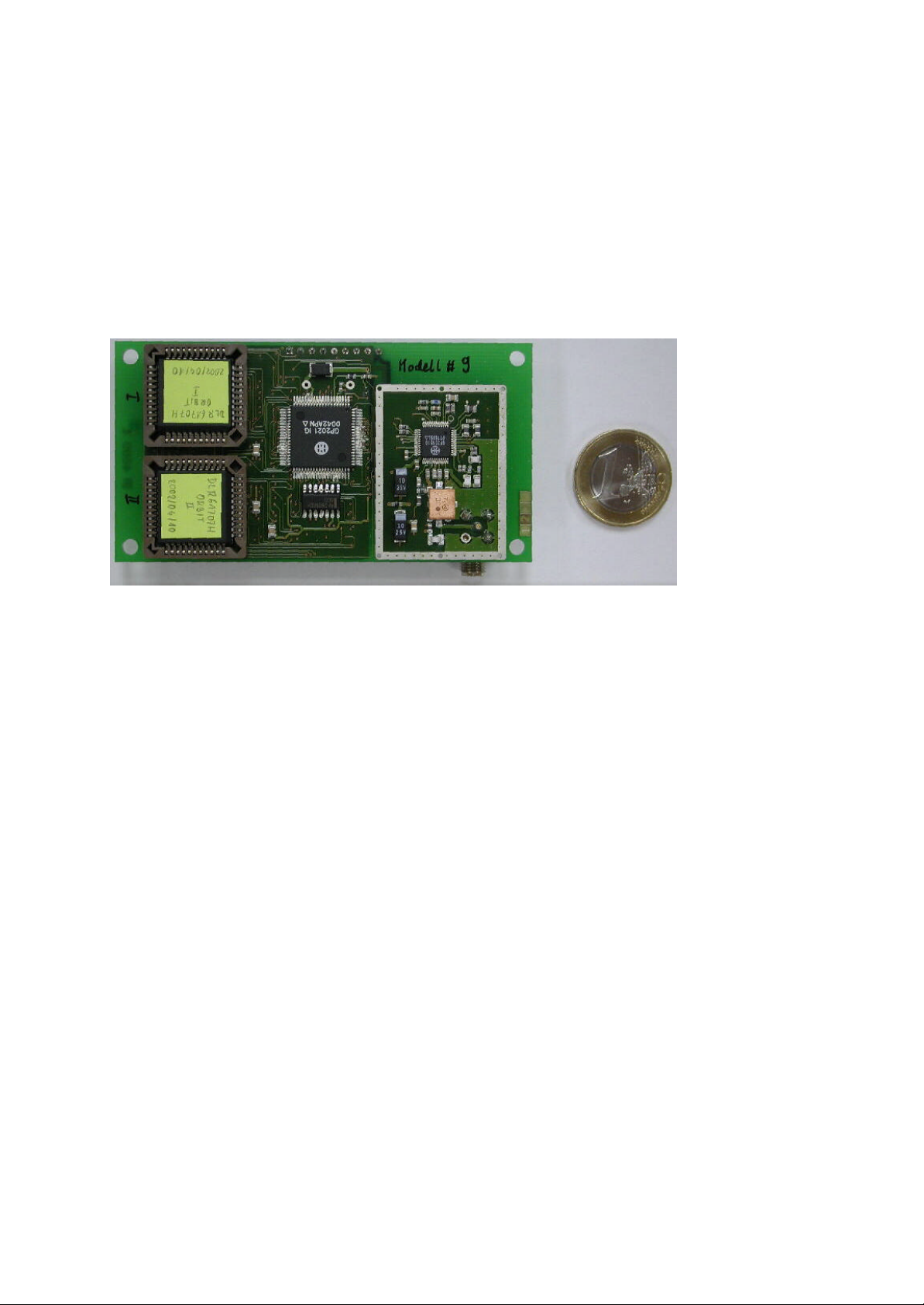
The GPS Orion receiver represents a prototype design of a terrestrial GPS receiver for 12
channel single frequency tracking built around the Mitel (now Zarlink) GP2000 chipset ([3],
[4]). The receiver main board comprises a GP2015 frontend and DW9255 saw filter, a
GP2021 correlator as well as an ARM60B 32-bit microprocessor. It can be supplemented by
an optional interface board featuring a switching regulator, serial line drivers (RS 232) and a
backup battery.
Fig. 1.1 GPS Orion main board
A basic software for the GPS Orion receiver has earlier been made available by Mitel Sem iconductor as part of the GPS Architect Development Kit. It is restricted to purely terrestrial
applications and has received numerous extensions and modifications to provide accurate
navigation under the rapidly varying signal conditions encountered in typical space missions.
Key upgrades include enhanced tracking loops, a synchronization of measurements to integer GPS seconds, the provision of precise carrier phase measurements, a revised navigation
algorithm, as well as a software based aiding of the signal acquisition using reference trajectory data. In addition to the above software changes, the original hardware design has been
amended by a supplementary pin for output of the pulse -per-second signal.
1.2 Functional Overview
DLR’s family of GPS Orion receivers comprises various firmware versions for space and high
dynamics applications. Available software configurations are:
• Orion-S for low Earth satellites and formation flying
• Orion-HD for high dynamics platform like sounding rockets and reentry vehicles
Features common to all receiver models are summarized below.
• 12 fully independent tracking channels
• 2-bit sampling
• 3rd order PLL with FLL assist
• Low noise code, carrier and Doppler measurements
• Acquisition aiding using reference trajectory information
• Navigation update rate of up to 2 Hz
• Configurable ASCII output messages in WinMon and NMEA format
• Pulse-per-second signal
• Low power consumption (2 W at 5 Volts)
Document No. Issue 1.0
GTN-MAN-0110 June 22, 2003
DLR/GSOCNo part of this document shall be reproduced in any form or disclosed to third parties without prior authorization.

Document Title: 4
User’s Manual for the GPS Orion-S/-HD Receiver
• Small form factor (50 x 95 mm) and weight (50 g)
• Sufficient radiation tolerance LEO usage
• Battery buffered non-volatile memory and real-time clock
• Two serial ports
• Discrete input pin
• 5V supply for active antenna (16-28dB)
• OrionMonitor control software for Windows PCs
A hardware description of the Orion-S/HD receiver is provided in Chap. 2 of this manual.
Chap.3 addresses the receiver operation and the command and log functionality is described
in full detail in Chap. 4.
1.3 Receiver Versions
The Orion receiver is available in various versions, which basically differ by the employed
receiver software. Aside from the standard receiver (Mitel reference design [3], [4]), which is
restricted to terrestrial applications, a space (-S) version and a high dynamics (-HD) version
are available. These employ specific trajectory models to enable a safe and rapid signal acquisition under rapid motion of the host vehicle. For satellites in low Earth orbit, aiding is provided by an analytical orbit model using twoline elements, whereas a set of piecewise polynomials is employed to approximate the trajectory of ballistic vehicles (sounding rockets, reentry capsules) in the HD version. Various commands specific to each of these versions are
provided to load, dump and use the respective aiding information.
The two versions also differ by their choice of FLL/PLL loop settings that are adapted to the
specific application needs. A narrow bandwidth of the carrier tracking loop is chosen in the
Orion-S receivers to achieve the most accurate carrier phase measurements under typical
line-of-sight accelerations of 1 G. Wide bandwidth settings, in contrast are chosen for in the
HD receivers to accommodate the extreme dynamics of a powered flight and the re-entry
shock.
Finally, a relative navigation mode is offered by the Orion-S receiver to support its use in
basic formation flying and rendezvous & docking applications.
A detailed account of the prototype software for the GPS Orion receiver is given in the GPS
Architect Software Design Manual [5]. Subsequent modifications for the S and HD version
are described in [6].
Document No. Issue 1.0
GTN-MAN-0110 June 22, 2003
DLR/GSOCNo part of this document shall be reproduced in any form or disclosed to third parties without prior authorization.
Document Title: 5
User’s Manual for the GPS Orion-S/-HD Receiver
2. Receiver Hardware
2.1 Main Board
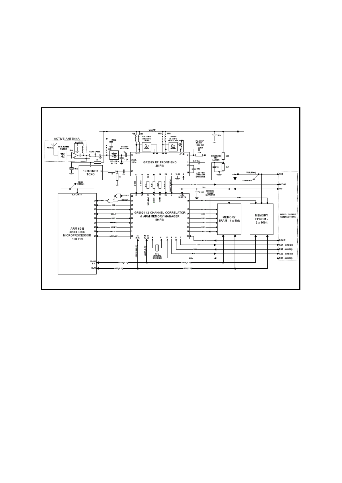
A block diagram of the GPS Orion receiver main board is shown in Fig. 2.1 ([4]). The receiver
is designed to work with an active antenna and +5 V power supply for the preamplifier is provided on the central antenna feed.
Fig 2.1 Block diagram of the GPS Orion receiver main board (from [4])
After passing an R/F ceramic filter, the L1 signal (1575.42 MHz) is down-converted and digitized in the GP2015 front-end chip [7]. An external discrete filter and a DW9255 SAW filter [8]
are used to filter the first (175.42 MHz) and second (35.42 MHz) intermediate frequencies,
while an on-chip filter is used for the third analog IF (4.31 MHz). Finally, the signal is digitized
and sampled to create a digital IF of 1.405 MHz with 2-bit quantization. The fundamental
reference frequency for the mixing process is provided by a 10.0 MHz TCXO with a specified
stability of 2.5 ppm. I t also used to derive a 40 MHz clock frequency for the correlator.
The subsequent signal processing is performed in the GP2021 correlator chip [9], which provides 12 fully independent C/A code correlator channels. It also offers two UART ports for
external I/O as well basic memory management capabilities that can be used when working
with the ARM micro-processor. The GP2021 chip furthermore maintains a low accuracy realtime clock fed by a 32.568 kHz crystal. It also derives a 20 MHz clock frequency for the ARM
processor.
All software tasks operate in the 32-bit P60ARM-B micro-processor [10] that provides a peak
performance of 20 MIPS and has a typical spare capacity of 35% at 1 Hz navigation rate and
25% at 2 Hz. Upon start-up (or a reset) of the receiver, a boot loader (stored in EPROM) is
activated that copies the executable code and initialisation data from the EPROM into the
Document No. Issue 1.0
GTN-MAN-0110 June 22, 2003
DLR/GSOCNo part of this document shall be reproduced in any form or disclosed to third parties without prior authorization.

Document Title: 6
User’s Manual for the GPS Orion-S/-HD Receiver
RAM memory. The EPROM is arranged into two 16 bit wide chips (256 kB total), while RAM
is partitioned into four 8 bit wide memory chips with a total size 512 kB. The RAM memory
contents can be maintained by a dedicated backup power supply line with a current of approximately 0.1 mA.
The main board offers an SMA (or MCX) connector for the GPS antenna. It is connected to
the interface board via a 9-pin header that provides two bi-directional serial lines, the main
and backup power supply, an input discrete and a reset line. Optionally, a tenth pin is made
available for the pulse-per-second signal. A summary of the pin assignment is provided in
Table 2.1.
Table 2.1 Pin assignment for GPS Orion interface connector
Pin Function
1 Ground
2 Vdr (memory backup positive supply)
3 RX B serial input
4 RX A serial input
5 TX B serial out put
6 TX A serial output
7 Discrete input line (used as a “lift-off” signal)
8 Vdd level sense circuit output (used as a “reset” if connected to GND)
9 Vdd (+5V prime power supply input)
10 PPS output (optional)
General physical and electrical parameters of the Orion main board are summarized in Table
2.2. The GPS Orion receiver and its components have not been validated for space applications. Nevertheless, limited information on the radiation hardness of the core chipset suggests it’s suitability up to a total dose of about 15 krad [11]. However, no latch-up protection
is presently provided to safeguard against destruction of CMOS circuits under the action of
heavy ions. Other than the standard Orion receiver, the main boards of the Orion-S and -HD
receivers are not equipped with a “supercap” capacitor, since this is not considered vacuum proof. This means that the non-volatile memory and real-time clock is lost whenever the main
board is disconnected from the backup power su pply (pin 2).
Table 2.2 Physical and electrical parameters of GPS Orion main board
Parameter Value
Dimension 95mm x 50mm x ~10mm
Weight ca. 50g
Operations Temperature -40°C to +85°C (as per [1])
Storage Temperature -50°C to +110°C (as per[1])
Main power supply +5V DC (+/- 10%), 400 mA (2W)
Backup power supply
Data I/O levels CMOS TTL (0V, +5V)
RF input
Connector SMA (or MCX)
Active antenna power supply +5V DC, 50 mA
Impedance
>+2.2V DC, ca. 100 µA
50Ω
Document No. Issue 1.0
GTN-MAN-0110 June 22, 2003
DLR/GSOCNo part of this document shall be reproduced in any form or disclosed to third parties without prior authorization.
Document Title: 7
User’s Manual for the GPS Orion-S/-HD Receiver
2.2 Interface Board
The interface board provides auxiliary devices that are required for standalone operation of
the Orion receivers. It comprises
• a switching regulator allowing operation from unregulated power supplies,
• a rechargeable battery to maintain the non-volatile memory and real-time clock during
power down times and
• two RS232 serial line drivers for communication with standard peripheral devices.
Key parameters of the interface board are summarized in Table 2.2.
Table 2.2 Physical and electrical parameters of GPS Orion interface board
Parameter Value
Dimension 95mm x 50mm x 20mm
Weight 70g
Operating voltage 8–30V
Efficiency of switching regulator 85%
Total power consumption (I/F and main board) 2.4 W
Battery +3.6V NiCad, 110 mAh ([1])
I/O ports 2 x RS232 (±10V)
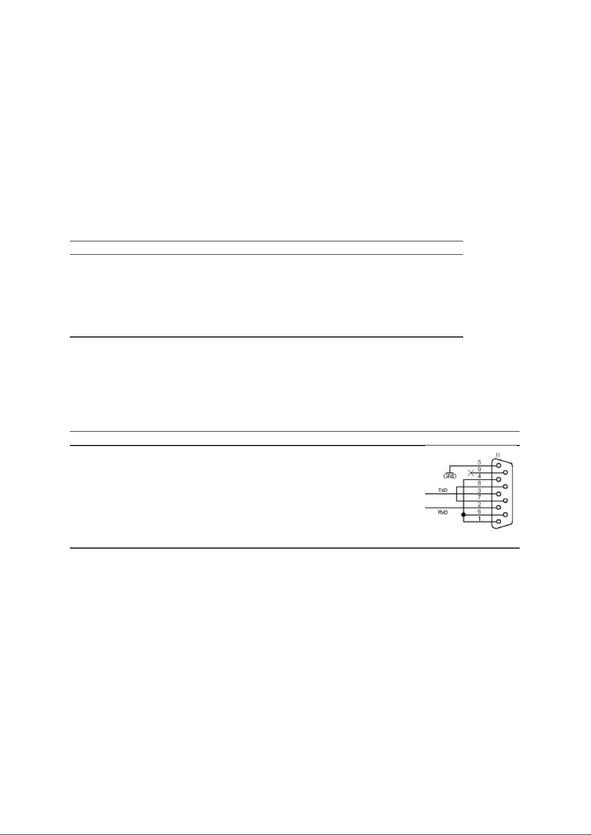
The two serial ports support the ground, receive and transmit line using the standard pin assignment for Sub-D9 connectors (Table 2.2). Pins 7 and 8 are cros s-connected since the
Orion receiver does not support a hardware handshake. Likewise the three pins 1, 4, and 6
are connected among each other.
Sub-D9 connector (male)
Table 2.2 Pin assignment for RS232 Sub-D9 connectors (Port A and B)
Pin Description Remarks Schematic
1 DCD (Data Channel Received
Line Signal Detector)
2 RxD (Receive Data)
3 Tx D (Transmit Data)
4 DTR (Data Terminal Ready) Connected with DCD and DSR (pins 1, 6)
5 GND (Signal Ground)
6 DSR (Data Set Ready) Connected with DCD and DTR (pins 1, 4)
7 RTS (Request to Send ) Connected with CTS (pin 8)
8 CTS (Clear to Send) Connected with RTS (pin 7)
9 RI (Ring Indicator) Not connected
Connected with DTR and DSR (pins 4, 6)
2.3 Antenna
The GPS Orion receiver is operated with an active antenna (or a passive antenna and external preamplifier) having a minimum gain of 16 dB and a noise-figure of less than 4 dB More
specifically, the ANPC-131 antenna of M/A COM is recommended (cf. [4]), for terrestrial applications. It offers an LNA gain of +26 dB and a 1.5 dB noise-figure at the L1 frequency
(1575.42 MHz).
For space applications dedicated antenna designs with heat and vacuum resistant radomes
are generally required. For sounding rockets wrap around antennas, helix tip antennas or
blade antennas with separate preamplifiers are available on request. GPS antennas for
satellite applications are offered by e.g. Sensor Systems Inc.
Document No. Issue 1.0
GTN-MAN-0110 June 22, 2003
DLR/GSOCNo part of this document shall be reproduced in any form or disclosed to third parties without prior authorization.

Document Title: 8
User’s Manual for the GPS Orion-S/-HD Receiver
3. Operations Guide
3.1 Basic Receiver Handling
3.1.1 Hardware Setup
For operating the GPS Orion receiver in a ground based test environment, the following
hardware items are typically required:
• Orion main board
• Orion interface board with power cable
• Power supply or battery (typically +12 V, 250 mA)
• Active GPS antenna (ca. 26 dB gain) with cable and SMA (or MCX) connector (male)
• PC with Windows operating system
• Serial interface cable (cross-link with female-female sub-D9 connectors)
Upon first operation, mount the main board on top of the interface board and connect both
board via the 9-pin connector. Since the standard interface board provides no PPS interface,
pin 10 of the main board (optional) will remain unused in this configuration. Next,
• connect the active antenna to the antenna plug on the main board
• connect port A (left) of the interface board to the PC’s COM1 port
• connect blue cable to ground pin of power supply (minus pole of battery)
The receiver will start to operate once the red cable is connected to the plus pole of the
power supply.
3.1.2 Precautions
To avoid an undesirable behavior or even destruction of the receiver, the following handling
instructions shall be considered:
• The center pin of the antenna connector provides a +5V power supply for the low
noise amplifier of an active GPS antenna. To avoid short cuts it is strongly advisable
to disconnect the receiver from the power supply prior to (dis -)connecting the antenna
or pre-amplifier.
• R/F attenuators between the receiver and the pre-amplifier must be equipped with a
DC by-pass to avoid heating of the attenuator or an overload of the receiver’s DC
power feed.
• Always connect the plus pin of the power supply last and disconnect it first. Otherwise
spurious ground connections via the serial cable or the antenna line may keep the receiver unintentionally powered up.
3.1.3 Serial Communication
The Orion-S and -HD receivers use port A (left connector) as the prime port for command
input and message output. By default, this port employs the following RS232 communication
parameters:
• 19200 baud
• no parity
• 8 data bits
• 1 stop bit
• no handshaking
Document No. Issue 1.0
GTN-MAN-0110 June 22, 2003
DLR/GSOCNo part of this document shall be reproduced in any form or disclosed to third parties without prior authorization.

Document Title: 9
User’s Manual for the GPS Orion-S/-HD Receiver
For proper communication, these values must match the settings of the PC communication
port.
While the Orion receiver is most conveniently used via a dedicated monitoring and control
program (e.g. OrionMonitor), elementary operations may likewise be carried out via a standard terminal program. As an example, the HyperTerminal program provided with the Windows operating systems can be used to monitor receiver output messages in real-time and to
record the data stream to a file. Vice-versa, commands can be loaded to the receiver from
pre-configured files or entered via the keyboard. In the latter case, the STX (0x02) and ETX
(0x03) characters marking the command start and end can be generated by pressing the
CNTL-B and CNTL-C keys, respectively. If desired, consecutive commands may be separated by white space like blanks or line feeds. Please note, that the correct checksum must
be provided for each command to allow proper execution.
3.1.4 Start-Up and Initialization
At power-up the receiver performs the following initialization steps:
• The boot loader is executed and the program code is loaded from EPROM to RAM
memory.
• If non-volatile memory has been retained since the previous activation, the receiver
restores the latest almanac, broadcast ephemerides, ionospheric and UTC parameters, trajectory aiding parameters, as well as the cu rrent time.
• If the receiver was temporarily disconnected from the backup power supply or the respective NVM data are corrupted, the time, almanac and trajectory aiding parameters
are initialized with hard-coded default data (Note: The actual values used for the de-
fault initialization depend on the particular software release and may vary between
receivers). The ephemeris data are marked as unavailable.
• A boot message identifying the current software version is issued.
Subsequently, the signal tracking is started and the receiver starts outputting a predefined
sequence of messages at a 1 Hz rate. The same steps are performed when the reset button
on the interface board is pressed.
Depending on its previous usage the receiver should start tracking and deliver navigation
fixes between a minimum of 30 s (hot start with known time, position and ephemerides) and
a maximum of 15 min (cold start). To speed-up the signal acquisition various commands can
be employed to provide the receiver with a priori information. A comprehensive initialization
sequence is listed below. Some steps are optional and may be skipped as desired.
• To discard all existing receiver settings issue the CS (cold start) command followed
by a reset (or reboot) of the receiver. This will return the receiver into a native state
with time, almanac, and trajectory aiding parameters determined by the firmware defaults.
• Set the current date and time (using the SD and ST commands). For static receiver
operation an accuracy of 10 min is generally sufficient. For LEO operations and initializations in the free-flight phase of ballistic vehicles a maximum error of 10 s is tolerable.
• For unaided operation, set the geographic coordinates (using the IP command) or the
initial state vector (using the PV command). For static receiver operation an accuracy
of 1° is generally sufficient and the altitude can be assumed as zero (sea level).
• For aided operation set the trajectory parameters (using the LO command for LEO
operations or the LT and ET commands for ballistic trajectories).
• Load a set of current almanac parameters based on e.g. a YUMA almanac (using the
LA and F13 commands). If desired, the almanac may be complemented by ionospheric correction data and UTC leap second information (F15 command).
Document No. Issue 1.0
GTN-MAN-0110 June 22, 2003
DLR/GSOCNo part of this document shall be reproduced in any form or disclosed to third parties without prior authorization.

Document Title: 10
User’s Manual for the GPS Orion-S/-HD Receiver
• If the above steps have taken more than two minutes, the receiver may have started
to scan through the permitted range of frequency bins. Reset or reboot the receiver to
start the signal search in the central frequency bin.
• Select the desired aiding mode (using the AM command).
• Set other operations parameters (e.g. output rates, elevation mask, etc.) as desired.
The receiver should now be indicating proper tracking and a valid 3D navigation fix as part of
the periodic navigation and status messages.
3.1.5 Output Selection
The output of the GPS Orion-S/HD receiver can, to a limited degree, be configured according
to the user needs. All relevant commands and the available output messages are des cribed
in full detail in Chap. 4 of this User’s Guide.
In start-up configuration1 the receiver outputs an F00 (geodetic) and F40 (Cartesian) navigation message with time, position and velocity as well as the number of tracked satellites once
per second. Channel status information is available as part of the F03 or F43 message that is
likewise issued at the 1 Hz update rate. Navigation and status data belong to a class of periodic receiver messages that can be controlled using the DR (Data Rate) command. It sets
the output interval of a specified message number in multiples of the navigation interval. Furthermore messages can be polled once or disabled completely. The data rate selection is
available for the F00/03/04/05/08 WinMon messages (i.e. the standard Mitel message set of
the original Orion receiver firmware), the F40/41/42/43/45/46/47/48 WinMon messages (specific for the Orion-S and/or –HD receiver) as well as a limited set of standard and proprietary
NMEA type navigation and status messages.
Dedicated commands are available for polling specific configuration and operations param eter on demand. These comprise the SA command (Send Almanac, ephemerides and
iono/UTC data), the TA command (Transmit Almanac), the TE command (Transmit Ephemeris), the TO command (transmit orbit) and the TT (Transmit Trajectory) command.
Aside from the periodic and polled outputs, the receiver autonomously issues various messages on the occasion of special events:
• At start-up, a boot message (F99 format) is transmitted that identifies the current
software version.
• Upon reception and processing of most commands a response message (F98 format)
is issued.
• Broadcast ephemeris parameters (F14 message) are transmitted in the Orion-S at
start-up and whenever new values become available as part of the GPS navigation
message.
These messages are cannot be deactivated and may result in temporary output buffer overflows, when the communication channel does not provide a sufficient bandwidth for all periodic and non-periodic data.
1
On customer request, other default configurations may be implemented in the firmware of project specific sof t-
ware releases.
Document No. Issue 1.0
GTN-MAN-0110 June 22, 2003
DLR/GSOCNo part of this document shall be reproduced in any form or disclosed to third parties without prior authorization.

Document Title: 11
User’s Manual for the GPS Orion-S/-HD Receiver
3.1.6 Pulse-per-Second Signal
Supporting receiver versions provide a one-pulse-per-second signal (CMOS TTL level) at pin
10 of the interface connector. The PPS signal is available in case of valid navigation. It has a
one millisecond duration and its starting edge is aligned to the occurrence of an integer GPS
second with an accuracy of better than 1 µs. The typical error amounts t ca. 0.2 µs and is
determined by the limited resolution of the correlator timing (175 ns) and the accuracy with
which the modelled GPS time of the receiver matches the true GPS system time (<0.1 µs
with S/A off). When using long antenna cables in ground based tests, the PPS will experience a systematic shift in accord with the added si gnal time.
Irrespective of the availability of an output pin for the PPS hardware signal, the measurements and navigation solution of the receiver are aligned to the integer GPS second whenever a continuous 3D navigation solution has been achieved.
3.1.7 Troubleshooting
If deemed necessary, various electrical and functional checks may be performed at any time
to validate the proper receiver operation:
• The product of the supply voltage and current consumption shall match the nominal
power consumption of 2.4±0.1W. A lower value may indicate errors in the boot process caused by e.g. twisted EPROMs or a broken address/data line on the main
board.
• When connected to a terminal program, the receiver shall output a continuous stream
of (mostly numeric) ASCII characters. Failures to do so may indicate problems with
the physical connection (e.g. twisted RX/TX lines of the serial cable) or a wrong configuration (baud rate, etc.) of the PCs COM port.
• The receiver shall respond to commands (for a simple test, try the <STX>DR0010A<ETX> and <STX>DR000117<ETX> commands to toggle the F00 message output). Failures may again indicate problems with the physical connection or the communication software.
• With adequate open sky visibility the receiver shall achieve code lock (“C”) with an
SNR value of better than 10 dB on (at least) one channel within a maximum of 5 min
irrespective of its initialization state. Otherwise, problems in the antenna system (passive versus active antenna, inappropriate or erroneously connected pre-amplifier,
broken antenna cable, etc.) may be su spected.
• If other problems in the antenna system can be ruled out, one may further verify that
the center pin of the antenna connector has a DC level of +5.0±0.1V with respect to
ground.
In case of persistent failures inspection by the manufacturer may be required.
Document No. Issue 1.0
GTN-MAN-0110 June 22, 2003
DLR/GSOCNo part of this document shall be reproduced in any form or disclosed to third parties without prior authorization.
Document Title: 12
User’s Manual for the GPS Orion-S/-HD Receiver
3.2 Special Applications
3.2.1 Aiding for Ballistic Trajectories
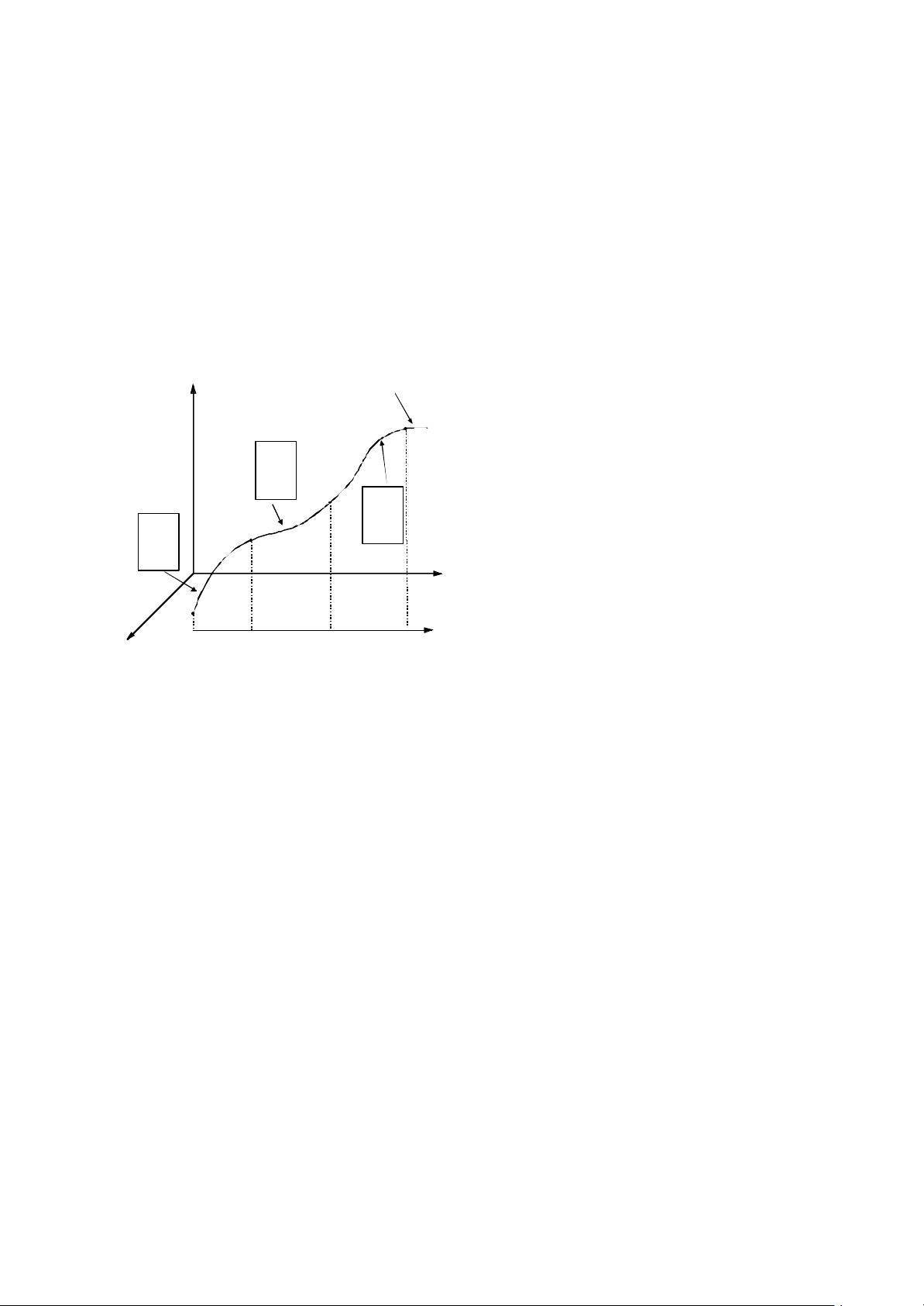
To allow a rapid acquisition and an optimal channel allocation in case of high vehicle dynamics the Orion-HD receiver can be aided by a priori trajectory information. For sounding roc kets or other ballistic mis sions the nominal flight path is represented by a piecewise, low order
polynomial approximation stored within the receiver (Fig. 3.1, [12]). Using this information the
GPS satellites in view and the expected Doppler shift can be computed at any time after
launch.
z
w0,t
0
ax,bx,c
x
ay,by,c
y
az,bz,c
z
w0,t
0
ax,bx,c
x
ay,by,c
y
az,bz,c
z
x
Fig. 3.1 Piecewise polynomial approximation of the reference trajectory of a sounding rocket. Each time interval
is represented by its start epoch (GPS week and seconds) and three coefficients per axis.
1st segment 2nd segment
Sounding Rocket
Trajectory
w0,t
0
ax,bx,c
ay,by,c
az,bz,c
3rd segment
x
y
z
y
Time
To minimize the computational workload in each step, a simple 2nd-order polynomial
t
=r (3.1)
a
y
=
a
z
a
x
b
x
y
z
x
b
+
y
b
z
c
x
c
tt
+−
y
c
z
2
)()()( tt
−
00
is used to approximate the trajectory over discrete time intervals in the WGS84 reference
frame. Upon differentiation, one obtains an associated approximation of the instantaneous
Earth-fixed velocity vector
&
b
x
&
y
t
=
v , (3.2)
&
z
x
b
=
y
b
z
c
x
c
+
y
c
z
)(2)(
tt
−
0
which is linear in time. Accordingly, the individual time intervals should be chosen in such a
way as to exhibit a near constant acceleration. Up to 15 polynomials can be configured and
stored which is sufficient to provide a position accuracy of about 2 km and a velocity accuracy of roughly 100 m/s in representative mi ssions.
Based on the polynomial approximation of the nominal trajectory, the reference position and
velocity of the host vehicle are computed once per second. The result is then used to obtain
the line-of-sight velocity and Doppler frequency shift for each visible satellite, which in turn
serve as initial values for the steering of the delay and frequency locked loops. The positionvelocity aiding thus assists the receiver in a fast acquisition or re-acquisition of the GPS sig-
Document No. Issue 1.0
GTN-MAN-0110 June 22, 2003
DLR/GSOCNo part of this document shall be reproduced in any form or disclosed to third parties without prior authorization.

Document Title: 13
User’s Manual for the GPS Orion-S/-HD Receiver
nals and ensures near-continuous tracking throughout the boost and free-flight phase of the
ballistic trajectory.
The command interface of the Orion-HD receiver supports a total of six different instructions
to support the handling of ballistic trajectory information:
• The LT (Load Trajectory) command initiates the upload of a set of trajectory polynomials.
• Each trajectory polynomial is then loaded in the form a single F51 command message.
• The sequence is terminated by the ET (End Trajectory) command.
• The reference epoch for the trajectory polynomials can be configured using the LE
(Load Epoch) command, unless it is automatically detected through a hardware lift-off
signal (see below).
• Using the TT (Transmit Trajectory) command, the currently loaded trajectory information can be dumped. When issued, the receiver outputs an F50 message providing
the reference epoch and sequence of F51 messages containing the individual trajectory polynomials.
• Finally, the aiding can be activated (or deactivated) through the AM (Aiding Mode)
command.
Both the reference epoch and the trajectory polynomials are stored in non-volatile memory
and made available upon a reboot of the receiver.
The aiding is designed to support a rapid acquisition and re-acquisition after temp orary signal
losses. It controls the initial configuration of a previously void tracking channel but has no
impact on those channels that have already achieved a continuous code and carrier lock and
follow the signal dynamics with their respective tracking loops. When aiding is activated, the
Doppler and visibility prediction depends only on the a priori trajectory polynom ials, and the
time since the reference epoch. As such, a faulty or outdated navigation solution has no impact on the initialization of new channels and safe acquisition can even be achieved if during
boosted flights that do not allow a linear prediction of the latest state vector. On the other
hand, erroneous values may be predicted in case of a m ajor deviation from the nominal flight
profile. The choic e of aided versus unaided operation must therefore be based on a careful
risk assessment. Aiding is clearly advisable, if continued tracking cannot be assured due to
e.g. a changing field-of-view or switching between antennas. Unaided operation, on the other
hand, may be preferable, if a stable initial acquisition and continued GPS visibility can be
assured but the actual flight profile is not know with good confidence before the mission.
3.2.2 Lift-off Signal
The discrete input pin of the GPS Orion-HD main board can be employed to automatically
sense the lift-off time of a sounding rocket and set the reference epoch for the trajectory aiding. The lift-off signal is defined to remain low while the rocket is grounded and switch to high
level at lift-off. While set to low, the receiver continuously overwrites the reference time for
the trajectory polynomials by the current time. This update is performed at each TIC and is
thus accurate to about 0.1 s. For proper function, the lift-off signal must remain high throughout the entire flight.
3.2.3 IIP Prediction
The instantaneous impact point (IIP) describes the touch-down point of a sounding rocket
under the assumption of an immediate end of the propelled flight. It is representative of a
situation in which the rocket motor is instantaneously switched off by the mission control ce nter following e.g. a guidance error during the boost phase. As part of the range safety operations during a sounding rocket launch, a real-time prediction of the IIP is performed to monitor the expected touch down point in case of a boost termination. The computation and dis-
Document No. Issue 1.0
GTN-MAN-0110 June 22, 2003
DLR/GSOCNo part of this document shall be reproduced in any form or disclosed to third parties without prior authorization.

Document Title: 14
User’s Manual for the GPS Orion-S/-HD Receiver
play of the IIP allows the range safety officer to discern whether the rocket would eventually
land outside the permissible range area and thus necessitate an abort of the boosted flight or
even a destruction of the ma lfunctioning vehicle.
For an optimal support of sounding rockets, the Orion-HD receiver is able to predict the instantaneous impact point (IIP) from its navigations solution. The instantaneous position and
velocity are expressed in the local horizontal coordinate system and a plane-Earth parabolic
trajectory model with first order corrections for surface curvature, gravity variation and Earth
rotation is used to predict the motion up to the intersection with the surfac e of the Earth [13].
Due to its inherent simplicity the analytical IIP model is well suited for real-time time computations but is still competitive in terms of accuracy. Comparisons have demonstrated that the
overall agreement with a full modeling of conservative forces is high enough to introduce IIP
prediction errors of less than 1.5% of the ground range for sounding rockets reaching altitudes of up to 700 km and flight times of about 15 min.
In view of negligible processor requirements, the IIP prediction is always performed along
with the navigation solution. However, the F47 or $PDLRM,IIP has to be activated (using the
DR Data Rate command) to output the geodetic impact point coordinates and the time to
impact.
Document No. Issue 1.0
GTN-MAN-0110 June 22, 2003
DLR/GSOCNo part of this document shall be reproduced in any form or disclosed to third parties without prior authorization.

Document Title: 15
User’s Manual for the GPS Orion-S/-HD Receiver
3.2.4 Aiding for LEO Satellites
The Orion-S receiver provides a dedicated aiding mode to support the GPS signal acquisition
onboard a low Earth orbiting (LEO) satellite. Similar to the HD receiver, it uses a coarse approximations of the nominal trajectory to forecast the vis ible GPS satellites and the expected
line-of-sight Doppler shift. This information is the used to allocate and initialize new tracking
channels. In accord with its primary application area, the Orion-S receiver employs the
SGP4 orbit model for LEO satellites [14] to predict the user spacecraft trajectory from
NORAD twoline element data sets.
Twoline elements comprise 2 lines of 69 characters each (cf. Table 3.1) to specify the epoch
and the orbital elements of a satellite, as well as information on the secular change in the
mean motion and on the ballistic coefficient (or the second derivative of the mean motion).
They also give the international satellite ID, an element number and a revolution number.
Each line contains a checksum at the end to guard against transmission errors.
Table 3.1 Description of the contents of NASA/NORAD 2-line element records
Column Description Line 1
01-01
03-07
10-11
12-14
15-17
19-20
21-32
34-43
45-52
54-61
63-63
65-68
69-69
Column Description Line 2
01-01
03-07
09-16
18-25
27-33
35-42
44-51
53-63
64-68
69-69
Line number of element data
Satellite number
International Designator (last two digits of launch year)
International designator (launch number of year)
International designator (piece of launch)
Year of epoch (last two digits)
t0; day of epoch (day of year and fractional day )
1/2·dn0/dt; the time rate of change in the „mean“ mean motion (in units of [rev/d2]),
or the ballistic coefficient B (depending on ephemeris type)
1/6·d2n0/dt2; the second time rate of change in the „mean“ mean motion (in units of [rev/d3]). A decimal point is assumed between columns 45 and 46. Will be left blank if not applicable (see above)
B*=1/2· Bρ0, where B=1/2· CD· A/m is the drag term (in units of [1/R⊕]; a decimal point is assumed
between columns 54 and 55
Ephemeris type
Element number
Check sum for line 1 (modulo 10); numbers count face value, letters and blanks as 0, periods and
plus signs as 0, minus signs as 1
Line number of element data
Satellite number
i0; the mean inclination (in [°])
Ω0; the mean right ascension of the ascending node (in [°])
e0; the mean eccentricity. A decimal point is assumed between columns 26 and 27
ω0; the mean argument of perigee (in [°])
M0; the „mean“ mean anomaly (in [°])
n0; the „mean“ mean motion (in [rev/d]) dependent on SGP type
Revolution number
Check sum for line 2 (modulo 10)
The orbital elements are mean Keplerian elements (with the number of revolutions per day
substituting the semi-major axis), which best represent the actual trajectory when used in
combination with the SGP4 (or SDP4) orbit propagators. The SGP4 orbit model was developed in 1970 based on the analytical perturbation theory of Brouwer and accounts for the
Earth gravity field through zonal parameters J2, J3 and J4 and the atmospheric drag through a
power density function assuming a non-rotating, spherical atmosphere. It is recommended
for satellites in near-circular orbits with typical periods of less than 225 min.
Document No. Issue 1.0
GTN-MAN-0110 June 22, 2003
DLR/GSOCNo part of this document shall be reproduced in any form or disclosed to third parties without prior authorization.

Document Title: 16
User’s Manual for the GPS Orion-S/-HD Receiver
Aided operation of the Orion-S receiver is supported by a variety of dedicated commands:
• For configuring the orbital elements of the user satellite, the LO (Load Orbit) command is used. The first and second line of the elements set are each embedded into
a separate LO command and consecutively transmitted to the receiver.
• Using the TO (Transmit Orbit) command the currently loaded mean orbital elements
can always be dumped in the form of a single F52 output message.
• Aiding is activated (or deact ivated) using the AM (Aiding Mode) command.
Upon commanding, a new element set is always stored in non-volatile memory. The information is thus preserved and made available again after a reboot of the receiver. This allows a
power saving, intermitted operation, in which the receiver is powered up for only som e parts
of each orbit.
Use of the aiding mode provides a particularly simple way to initialize the receiver on a LEO
satellite, since a single element set is good for initialization at multiple epochs. Typically, the
twoline elements are accurate enough to allow aiding for a period of at least one week following their validity epoch. If continuous tracking can be ensured by an appropriate antenna
orientation and elevation mask, the receiver may be commanded to unaided mode after successful acquisition of a 3D navigation fix. It will henceforth use the latest navigation solution
to forecast the instantaneous visibility conditions and expected Doppler shifts of the GPS
satellites.
3.2.5 Relative Navigation
The Orion-S receiver operates a DGPS task providing simple relative navigation of two host
vehicles via the exchange of raw navigation solutions. To operate the relative navigation feature, the secondary I/O ports (port B) of two receivers must be connected via a bi-directional
serial radio link with a 19.2 kB data rate. On the B port, each receiver outputs an F40 navigation message as well as an F42 raw data message once per second. Vice versa, it decodes
F42 messages on input and uses them to compute a differential navigation solution. The
remote measurements are differenced against the receiver’s own raw data thus eliminating
common errors like GPS clock errors, broadcasts ephemeris and to a fair degree ionospheric
errors. A differential position is then computed after carrier smoothing of the differenced
pseudorange measurements. Likewise, velocity is obtained from differential range rate
measurements that are derived from a second order polynomial approximating the differential carrier phases. Further details of the employed algorithms and concepts are provided in
[15]. The achieved accuracy amounts to typically 0.5 m in position and 0.5 cm/s velocity.
For orbital applications the resulting relative navigation solution can conveniently be output in
a reference frame aligned with the radial, along-track and cross-track direction, but a standard WGS -84 representation is also available. In either case it is necessary to activate the
respective output message (F45 or F46) using the DR (Data Rate command). Note that the
relative navigation solution is always one second late compared to the standard navigation
output to accommodate the required time for exchanging raw measurements via the auxiliary
port.
Document No. Issue 1.0
GTN-MAN-0110 June 22, 2003
DLR/GSOCNo part of this document shall be reproduced in any form or disclosed to third parties without prior authorization.

Document Title: 17
User’s Manual for the GPS Orion-S/-HD Receiver
3.2.6 External LNA Power Supply
The antenna line of the Orion GPS receiver provides a +5V DC power level to feed a low
noise amplifier with a maximum current consumption of about 50 mA. In some cases this
specification may not be appropriate and an external power supply be required. Possible
applications include e.g. the use of multiple parallel antennas or the use of miniature antennas with 3.3V LNA. In this case a “bias -T” is employed to block the DC supply of the receiver
(via a built-in capacitor) and to insert the external supply voltage (via an R/F isolating inductivity) to the subsequent antenna line. An added advantage of the external DC power supply
is the possibility to apply a current limitation and thus protect the receiver front-end against
short cuts in the antenna system.
Fig. 3.1 Schematic view of external LNA power supply using a bias-T
A block diagram showing the connection of receiver, bias-T, external supply and preamplifier is given in Fig. 3.1. Bias -Ts suitable for GPS frequencies are available from various
manufacturers including M/A COM, Pasternak, etc.
Document No. Issue 1.0
GTN-MAN-0110 June 22, 2003
DLR/GSOCNo part of this document shall be reproduced in any form or disclosed to third parties without prior authorization.

Document Title: 18
User’s Manual for the GPS Orion-S/-HD Receiver
4. Command and Output Message Reference
4.1 Overview
A summary of the available commands and output messages for the Orion-HD and –S receivers is provided in the subsequent table:
Table 4.1 GPS Orion commands and output messages
MsgID Type Format Receiver Description
AC cmd WinMon all All assign PRN to all channels
AM cmd WinMon HD, S Select aiding mode
CH cmd WinMon all Set number of active channels
CS cmd WinMon all Cold start
DR cmd WinMon HD, S Select the rate of receiver output messages
DS cmd WinMon all Deselect satellite
DW cmd WinMon HD, S Set Doppler window
EM cmd WinMon all Set elevation mask
ET cmd WinMon HD End of trajectory polynomials
IP cmd WinMon all Set initial position
LA cmd WinMon all Load almanacs
LE cmd WinMon HD Load epoch of trajectory polynomials
LO cmd WinMon S Load orbital elements
LT cmd WinMon HD Load trajectory polynomials
MC cmd WinMon HD, S Select application of media corrections
OE cmd WinMon all Set oscillator error
PM cmd WinMon all Set PDOP mask
PV cmd WinMon HD, S Set initial position and velocity
RH cmd WinMon all Set reference position to current position
RM (obsolete) cmd WinMon HD, S Select aiding mode
RP cmd WinMon all Set reference position
RS cmd WinMon all Re-select satellite
SA cmd WinMon all Save alma nac
SD cmd WinMon all Set date
SM cmd WinMon HD, S Choose between standard and extended Mitel format
SS cmd WinMon all Select satellite
ST cmd WinMon all Set time
TA cmd WinMon HD, S Transmit almanac
TE cmd WinMon S Transmit ephemeris
TM cmd WinMon all Select track mode
TO cmd WinMon S Transmit orbital elements
TT cmd WinMon HD Transmit trajectory polynomials
UR cmd WinMon HD Set the navigation solution update rate
F00 out WinMon(ext) all Geographic navigation data (Mitel)
F03 out WinMon(ext) all Channel status (Mitel)
F04 out WinMon(ext) all Satellite summary (Mitel)
F05 out WinMon all Processing status (Mitel)
F08 out WinMon all Operating parameters (Mitel)
F13 out, in WinMon all Satellite almanac data
F14 out, in WinMon all Satellite ephemeris data
F15 out, in WinMon all Ionospheric/UTC model data
F40 out WinMon HD, S Cartesian navigation data
F41 out WinMon HD, S Pseudorange and range-rate (smoothed)
F42 out WinMon HD, S Pseudorange, carrier phase and range rate (raw)
F43 out WinMon HD, S Channel status
F44 out WinMon HD, S Clock data
F45 out WinMon S Relative navigation data (WGS-4 system)
F46 out WinMon S Relative navigation data (RTN frame)
F47 out WinMon HD Instantaneous impact point
F48 out WinMon HD, S Configuration and status parameters
Document No. Issue 1.0
GTN-MAN-0110 June 22, 2003
DLR/GSOCNo part of this document shall be reproduced in any form or disclosed to third parties without prior authorization.

Document Title: 19
User’s Manual for the GPS Orion-S/-HD Receiver
F50 out WinMon HD Reference epoch for trajectory polynomials
F51 out, in WinMon HD Trajectory polynomials
F52 out WinMon S User spacecraft mean elements
F99 out WinMon all Debug strings (log messages, command responses)
$GPGGA out NMEA all Position data
$PASHR,POS out NMEA HD Position and velocity data (Ashtech)
$PDLRM,IIP out NMEA HD Instantaneous impact point
$PDLRM,XSD out NMEA HD Extended status data
$PDLRM,RAW out NMEA HD Raw measurement data
Document No. Issue 1.0
GTN-MAN-0110 June 22, 2003
DLR/GSOCNo part of this document shall be reproduced in any form or disclosed to third parties without prior authorization.

Document Title: 20
User’s Manual for the GPS Orion-S/-HD Receiver
4.2 Protocol Description
The Orion-S and –HD receivers employ the Mitel proprietary WinMon format for commands
and output messages. In addition, selected NMEA type output messages are supported.
Other than in the standard GPS Orion firmware (cf. [2]), the choice of WinMon and/or NMEA
messages is not controlled by the discrete input pin (slide switch) but configured by command. If desired, both message types may simultaneously be activated in the output stream.
4.2.1 WinMon Format
A WinMon sentence is basically an ASCII text string composed of a command or message
identifier, the data portion and a hexadecimal checksum (Fig. 4.1). The sentence is embedded in a protocol frame made up of an initial Start of Transmission (STX) character (ASCII
0x02) and a terminating End of Transmission (ETX) character (ASCII 0x03).
STX C C x x x x … x x H H ETX
STX ‘F’ n n x x x … x x H H ETX
C = Alphabetic character (uppercase).
n = Decimal digit (0,…,9)
x = Data field.
H = Hexadecimal checksum character (uppercase).
STX = Start of Transmission (0x02).
ETX = End of Transmission (0x03).
Fig 4.1 WinMon sentence format and protocol frame for command (top) and output messages (bottom)
Command identifiers consist of two uppercase alphabetic characters, while a message identifier is made up of an initial ‘F’ character and a two digit decimal number2. The sentence
checksum is the hexadecimal representation of the exclusive-or of all the characters in the
sentence, excluding the <STX> and <ETX>. All data bytes contained in the data field of the
message are printable 7 bit characters (ASCII 32-127).
In extension of the original GPS Orion software, numerous new commands and output sentences have been defined for the Orion-S and –HD receiver. Other than in the default sentences, however, data fields of output messages are right justified for improved readability.
The format fields shown in the subsequent command and message descriptions illustrate the
fixed number of characters reserved for each data item, with “.” denoting the position of the
decimal point. Leading digits may be blank and an “s” indicates that the first non-blank character contains the sign of the respective quantity.
2
In extension of this rule, the F13, F14, F15, and F51 formats are jointly used for retrieving and loading specific
receiver data (almanac, ephemeris, ionosphere and trajectory parameters). However, these sentences must always follow a specific command (e.g. LA Load Almanacs) to initiate the upload and none of them w ill be processed on its own.
Document No. Issue 1.0
GTN-MAN-0110 June 22, 2003
DLR/GSOCNo part of this document shall be reproduced in any form or disclosed to third parties without prior authorization.

Document Title: 21
User’s Manual for the GPS Orion-S/-HD Receiver
4.2.2 NMEA Format
For compatibility reasons, a limited set of NMEA output messages is available in the Orion-S
and –HD receivers. Even though the NMEA format could likewise be applied for commanding, this option is not presently supported.
According to the NMEA-0183 standard, each message is initiated by a dollar (‘$’) character
and terminated by a carriage-return (CR, ASCII 0x13) and line-feed (LF, ASCII 0x10) record
delimiter (Fig. 4.2). The message header provides a unique five character identifier, which is
separated from the data field by a comma (‘,’). Commas are likewise used to separate individual items in the data field. This is followed by a footer comprising an asterisk (‘*’) and a
two character This checksum is calculated as the exclusive-or of all characters in the header
and data field, (i.e. in between but excluding the ‘$’ and ‘*’ characters) and expressed in uppercase hex format.
‘$’ C C C C C ‘,’ x x x … x x ‘*’ H H CR LF
C = Alphabetic character (uppercase).
x = Data field.
H = Hexadecimal checksum character (uppercase).
CR = Carriage return (0x13).
LF = Line feed (0x13).
Fig 4.2 NMEA format definition
Aside from the overall protocol, the NMEA standard specifically defines a set of default messages ($GPxxx) for use in common GPS receivers. Out of these, only the $GPGGA message is presently available in the Orion-S/HD receivers. Manufacturer specific NMEA messages supported by the receiver are designated by a $PASHR (Proprietary Ashtech Response) or $PDLRM (Proprietary DLR Message). In these cases, the first item of the data
field is a three character code that further specifies the message contents (e.g. $PDLRM,IIP
for instantaneous impact point coordinates).
NMEA messages typically do not provide a date field and are therefore ambiguous with a
24h period. If absolute timing is required, the WinMon messages should be preferred. All
time stamps in the NMEA messages are given in hours, minutes, and se conds referred to the
UTC system.
Document No. Issue 1.0
GTN-MAN-0110 June 22, 2003
DLR/GSOCNo part of this document shall be reproduced in any form or disclosed to third parties without prior authorization.

Document Title: 22
User’s Manual for the GPS Orion-S/-HD Receiver
4.3 Commands
The GPS Orion receiver scans the primary communication port for WinMon sentences embedded in the <STX>/<ETX> frame and starts the command processing, if the checksum test
is passed. Commands that are syntactically correct but do not match a supported command
identifier are ignored. In this case an F98 command response giving the current time and and
error message
E-id-Ignored unsupported command
(with id denoting the invalid command) is issued to the output.
Document No. Issue 1.0
GTN-MAN-0110 June 22, 2003
DLR/GSOCNo part of this document shall be reproduced in any form or disclosed to third parties without prior authorization.

Document Title: 23
User’s Manual for the GPS Orion-S/-HD Receiver
4.3.1 Basic Receiver Configuration
4.3.1.1 UR – Update Rate
The navigation solution update rate can be selected using the UR command within the limits
specified for a given receiver. Upon execution, the revised settings are acknowledged by one
of the following command responses:
I-UR-Update rate set to 1Hz
I-UR-Update rate set to 2Hz
I-UR-Update rate set to 5Hz
E-UR-Ignored (invalid argument)
CmdID Chars. Format Description
UR 7 Update Rate
1 x <STX>
2 xx Command Id (=UR)
1 x Rate [Hz] (supported values: 1Hz, 2Hz, 5Hz)
2 xx Checksum
1 x <ETX>
Examples:
<STX>UR136<ETX> Select 1 Hz navigation solution update rate (default)
<STX>UR235<ETX> Select 2 Hz navigation solution update rate (optional)
<STX>UR532<ETX> Select 5 Hz navigation solution update rate (optional)
Document No. Issue 1.0
GTN-MAN-0110 June 22, 2003
DLR/GSOCNo part of this document shall be reproduced in any form or disclosed to third parties without prior authorization.

Document Title: 24
User’s Manual for the GPS Orion-S/-HD Receiver
4.3.1.2 DR – Data Rate
The DR command provides the means for an individual configuration of receiver output messages. Sentences can be deact ivated completely, polled once or issued at selected intervals.
CmdID Chars. Format Description
DR 11 Data Rate
1 x <STX>
2 xx Command Id (=DR)
2 xx Message number
3 x(xx) Output interval (-1..127)
2 xx Checksum
1 x <ETX>
Notes:
• The output interval specifies the time between consecutive messages of the requested frame number in units of the time interval between navigation solutions (i.e.
1 s for 1 Hz version, 0.5 s for 2 Hz version)
• A value of “-1” for the output interval is used to deactivate a given message
• An output interval of “0” requests a one-time output (polling) of the given message
• Negative message numbers control the output of NMEA type message (-1=GPGGA,
etc.)
Examples:
<STX>DR400113<ETX> Issue the F40 navigation message at each update
<STX>DR43-10D<ETX> Deactivate the F43 channel status message
<STX>DR4802A<ETX> Poll the current configuration and status parameters (F48 msg.)
4.3.1.3 SM – Sentence Mode
The sentence mode command can be used to increase the field width of various Winmon
sentences (F00, F03, F04) to accommodate increased altitude, velocity and Doppler values
as encountered in typical space applications.
CmdID Chars. Format Description
SM 7 Sentence Mode
1 x <STX>
2 xx Command Id (=SM)
1 x Sentence Mode (0=Winmon,1=Winmon-X)
2 xx Checksum
1 x <ETX>
Example:
<STX>SM02E<ETX> Select standard WinMon format for F00, F03, and F04
<STX>SM12F<ETX> Select extended WinMon format
Document No. Issue 1.0
GTN-MAN-0110 June 22, 2003
DLR/GSOCNo part of this document shall be reproduced in any form or disclosed to third parties without prior authorization.

Document Title: 25
User’s Manual for the GPS Orion-S/-HD Receiver
4.3.1.4 MC – Media Correction
The MC command controls the application of media corrections to the raw measurements
prior to computing the navigation solution. The resulting status of the tropospheric correction
switch is confirmed by either of the following command replies:
I-MC-Tropospheric correction disabled
I-MC-Tropospheric correction enabled
E-MC-Ignored (invalid argument #1)
A second command reply out of
I-MC-Ionospheric correction disabled
I-MC-Ionospheric correction enabled
E-MC-Ignored (invalid argument #2)
gives the status of the tropospheric correction switch.
CmdID Chars. Format Description
MC 7 Media Correction
1 x <STX>
2 xx Command Id (=MC)
1 x Tropospheric correction (0=disabled ,1=enabled)
1 x Ionospheric correction (0=disabled ,1=enabled)
2 xx Checksum
1 x <ETX>
Notes:
• Media corrections are applied only to pseudorange measurements but not to range
rate data.
• No corrections are applied for GPS satellites below the horizon (0° elevation).
• The tropospheric range correction is altitude dependent and decreases exponentially
with a scale height of 7.5 km. It is thus applicable for all types of applications (terrestrial, ballistic, and LEO satellites)
• The ionospheric range delay is computed from the standard Klobuchar model, which
can only provide a coarse correction of the true effect. In particular, the model does
not depend on the actual altitude of the receiver. For LEO satellite applications, it is
recommended to deactivate the ionospheric co rrection.
Example:
<STX>MC000E<ETX> Deactivate all corrections
<STX>MC110E<ETX> Activate all corrections
<STX>MC100F<ETX> Activate tropospheric correction only
Document No. Issue 1.0
GTN-MAN-0110 June 22, 2003
DLR/GSOCNo part of this document shall be reproduced in any form or disclosed to third parties without prior authorization.

Document Title: 26
User’s Manual for the GPS Orion-S/-HD Receiver
4.3.2 Status Queries
4.3.2.1 TA – Transmit Almanac
The TA command initiates the output of 32 messages (F13) containing the current GPS almanac data.
CmdID Chars. Format Description
TA 6 Transmit Almanacs
1 x <STX>
2 xx Command Id (=TA)
2 xx Checksum
1 x <ETX>
Example:
<STX>TA15<ETX> Dump current almanac
4.3.2.2 TE – Transmit Ephemeris
The TE allows polling of GPS ephemeris data (F14 message) for one or all GPS satellites. In
case of an invalid argument the command is ignored and a response
I-TE-Ignored (invalid argument)
is issued.
CmdID Chars. Format Description
TE 6 Transmit Ephemeris
1 x <STX>
2 xx Command Id (=TE)
2 xx PRN of selected satellite; 00 requests complete set of 32 ephemerides
2 xx Checksum
1 x <ETX>
Notes:
• F14 ephemeris messages are also issued automatically, whenever updated GPS
data have been extracted from the navigation data stream broadcast by the GPS satellites.
Examples:
<STX>TE0011<ETX> Dump ephemerides for PRN 1 to 32
<STX>TE281B<ETX>Query ephemeris data for PRN 28
Document No. Issue 1.0
GTN-MAN-0110 June 22, 2003
DLR/GSOCNo part of this document shall be reproduced in any form or disclosed to third parties without prior authorization.

Document Title: 27
User’s Manual for the GPS Orion-S/-HD Receiver
4.3.3 Initialization
4.3.3.1 PV – Position-Velocity
The PV command sets the Cartesian position and velocity vector. It should be used instead
of the Initial Position (IP) command to initialise the receiver in unaided mode whenever its
velocity is larger than 50 m/s.
Execution of the command is acknowledged by an F98 command reply giving the message
I-PV-Updated current position and velocity
CmdID Chars. Format Description
PV 72 Set initial position and velocity
1 x <STX>
2 xx Command Id (=PV)
11 sxxxxxxxx.x x [m] (WGS-84)
11 sxxxxxxxx.x y [m] (WGS-84)
11 sxxxxxxxx.x z [m] (WGS-84)
11 sxxxxx.xxxx vx [m/s] (WGS-84)
11 sxxxxx.xxxx vy [m/s] (WGS-84)
11 sxxxxx.xxxx vz [m/s] (WGS-84)
2 xx Checksum
1 x <ETX>
Notes:
• Only the position component is stored in NVM.
Example:
<STX>PV -1075950.9 -5097588.2 +4403281.8 -876.4585 -4848.6594 -5817.75121B<ETX>
Document No. Issue 1.0
GTN-MAN-0110 June 22, 2003
DLR/GSOCNo part of this document shall be reproduced in any form or disclosed to third parties without prior authorization.

Document Title: 28
User’s Manual for the GPS Orion-S/-HD Receiver
4.3.3.2 DW – Doppler Window
If code lock for an allocated GPS satellite is not acquired within a given time, the search is
extended in neighbouring frequency bins at steps of ±500 Hz. The maximum Doppler offset
considered in this search can be specified by the DW command. Its value should account for
the expected reference frequency error (±1575 Hz at 1 ppm) and the uncertainty of the predicted Doppler shift. A peak line-of sight velocity of about 1000 m/s is encountered in terrestrial applic ations, thus requiring an additional ±5 kHz window in cold start tracking mode. For
LEO satellites, a window of up to ±40 kHz may be required.
Execution of the command is acknowledged by an F98 command reply of the form
I-DW-Changed Doppler window to 11500Hz
Negative input values are ignored and an error message
E-DW-Ignored (invalid argument)
is issued.
CmdID Chars. Format Description
DW 72 Set Doppler window
1 x <STX>
2 xx Command Id (=DW)
5 xxxxx Doppler search interval [Hz] (±value)
2 xx Checksum
1 x <ETX>
Notes:
• The specified search window is applied in cold start tracking mode or whenever a
navigation fix has not been achieved within the past two minutes. Otherwise a onebin search in the nominal Doppler window is carried out based on the available pos ition/velocity information and oscillator offset.
Example:
<STX>DW150000E<ETX> Extend frequency search to ±15 kHz
<STX>DW00E<ETX> Enforce one-bin Doppler window (requires accurate a priori
navigation information and oscillator error knowledge)
Document No. Issue 1.0
GTN-MAN-0110 June 22, 2003
DLR/GSOCNo part of this document shall be reproduced in any form or disclosed to third parties without prior authorization.

Document Title: 29
User’s Manual for the GPS Orion-S/-HD Receiver
4.3.4 Reference Trajectory Aiding
The Orion-S and –HD software versions support a software based aiding of the signal acquisition using reference trajectory information in the form of trajectory polynomials (for ballistic
flights) or twoline elements (for satellites in low Earth orbit). Aiding can be controlled by the
AM command and various other commands are available to store and retrieve the param eters of the reference trajectory. All relevant data are stored in non-volatile memory during
deactivation of the receiver.
4.3.4.1 AM – Aiding Mode
The Aiding Mode command is used to control the application of a priori trajectory information
in the Doppler and visibility computation for new tracking channels.
Upon execution of the command an F98 command response with either of the following information or errors messages is issued:
I-AM-Aiding disabled
I-AM-Aiding for ballistic trajectories enabled
I-AM-Aiding for low Earth orbits enabled
E-AM-Ignored unsupported aiding mode selection
CmdID Chars. Format Description
RM 7 Run Mode
1 x <STX>
2 xx Command Id (=AM)
1 x Aiding mode (0=unaided,1=ballistic, 2=orbit)
2 xx Checksum
1 x <ETX>
Notes:
• The Aiding Mode command replaces the obsolete RM (Run Mode) command
• Aiding mode 1 is only available in the Orion-HD receiver, aiding mode 2 is only avail-
able in the Orion-S receiver
Examples:
<STX>AM03C<ETX> Select unaided operation
<STX>AM13D<ETX> Select aiding for ballistic vehicles using trajectory polynomi als
<STX>AM23E<ETX> Select aiding for LEO satellites using twoline elements
4.3.4.2 RM – Run Mode
The run mode command is a syntactically identical but obsolete command for selecting the
aiding mode. It has been superseded by the AM (Aiding Mode) command in software versions D07L (Orion-S) and higher.
Examples:
<STX>RM02F<ETX> Select unaided operation
<STX>RM12E<ETX> Select aiding for ballistic vehicles using trajectory polynomials
<STX>RM22D<ETX> Select aiding for LEO satellites using twoline elements
Document No. Issue 1.0
GTN-MAN-0110 June 22, 2003
DLR/GSOCNo part of this document shall be reproduced in any form or disclosed to third parties without prior authorization.

Document Title: 30
User’s Manual for the GPS Orion-S/-HD Receiver
4.3.4.3 LO – Load Orbit
Twoline orbital elements for aiding the Orion receiver onboard a LEO satellite are loaded
using the LO command. One command each is required to upload the first and second line of
orbital parameters. Upon successful reception of the first comma nd, an information message
I-LO-Twoline elements line 1 received
is issued. Upon successful reception of the second command, acceptance of the new element set is confirmed by the message
I-LO-Twoline elements line 2 received
An inconsistent commanding is reported by an
E-LO-Ignored inconsistent twoline elements
error message.
CmdID Chars. Format Description
LO 75 Load Orbital Elements
1 x <STX>
2 xx Command Id (=LO)
69 69*x Twoline elements (line 1 or 2)
2 xx Checksum
1 x <ETX>
Examples:
<STX>LO1 12345U 01999 A 01309.99984954 -.00020228 00000-0 -46117-3 0 0421<ETX>
<STX>LO2 12345 87.0008 134.9419 0012185 296.6516 63.3393 15.42601037 093B<ETX>
4.3.4.4 TO – Transmit Orbit
The TO command initiates the output of an F52 message providing the mean orbital elements of the user spacecraft used for receiver aiding in low Earth orbits.
CmdID Chars. Format Description
TO 6 Transmit Orbital Elements
1 x <STX>
2 xx Command Id (=TO)
2 xx Checksum
1 x <ETX>
Example:
<STX>TO1B<ETX> Dump current orbital elements
Document No. Issue 1.0
GTN-MAN-0110 June 22, 2003
DLR/GSOCNo part of this document shall be reproduced in any form or disclosed to third parties without prior authorization.

Document Title: 31
User’s Manual for the GPS Orion-S/-HD Receiver
4.3.4.5 LE – Load Epoch
CmdID Chars. Format Description
LE 25 Load Epoch
1 x <STX>
2 xx Command Id (=LE)
4 xxxx Year
2 xx Month
2 xx Day
2 xx Hours
2 xx Minutes
4 xx.x Seconds
3 xxx Time system (UTC, GPS)
2 xx Checksum
1 x <ETX>
4.3.4.6 LT – Load Trajectory
CmdID Chars. Format Description
LT 6 Load Trajectory
1 x <STX>
1 x <STX>
2 xx Command Id (=LT)
2 xx Checksum
1 x <ETX>
4.3.4.7 ET – End Trajectory
The sequence of trajectory polynomials is terminated by the ET co mmand
CmdID Chars. Format Description
ET 6 End Trajectory
1 x <STX>
2 xx Command Id (=ET)
2 xx Checksum
1 x <ETX>
Example:
<STX>ET11<ETX> Dump current reference trajectory
4.3.4.8 TT – Transmit Trajectory
The TE command initiates the output of the reference epoch and the trajectory polynomials
uswed for aiding of ballistic vehicles.
CmdID Chars. Format Description
TT 6 Transmit Trajectory
1 x <STX>
2 xx Command Id (=TT)
2 xx Checksum
1 x <ETX>
Example:
<STX>TT00<ETX> Dump current reference trajectory
Document No. Issue 1.0
GTN-MAN-0110 June 22, 2003
DLR/GSOCNo part of this document shall be reproduced in any form or disclosed to third parties without prior authorization.

Document Title: 32
User’s Manual for the GPS Orion-S/-HD Receiver
4.4 Output Messages (WinMon Format)
4.4.1 Periodic Receiver Data
4.4.1.1 F00 – Geographic Navigation Data (Mitel)
See [2] for a complete message description.
4.4.1.2 F03 – Channel Status Data (Mitel)
See [2] for a complete message description.
4.4.1.3 F04 – Satellite Summary (Mitel)
See [2] for a complete message description.
4.4.1.4 F05 – Processing Status (Mitel)
See [2] for a complete message description.
4.4.1.5 F08 – Operating Parameters (Mitel)
See [2] for a complete message description.
Document No. Issue 1.0
GTN-MAN-0110 June 22, 2003
DLR/GSOCNo part of this document shall be reproduced in any form or disclosed to third parties without prior authorization.

Document Title: 33
User’s Manual for the GPS Orion-S/-HD Receiver
4.4.1.6 F40 – Cartesian Navigation Data
The F40 message provides the Cartesian state vector (position and velocity) of the host vehicle in the Earth-fixed WGS84 system. It is aligned to the instance of an integer GPS second once the receiver has a achieved continuous 3D navigation fix.
MsgID Chars. Format Description
F40 104 Cartesian navigation data
1 x <STX>
3 xxx Message Id (=F40)
4 xxxx GPS week
12 xxxxxx.xxxxx GPS seconds of week [s] (of navigation solution)
2 xx GPS-UTC [s]
12 sxxxxxxxx.xx x (WGS84) [m]
12 sxxxxxxxx.xx y (WGS84) [m]
12 sxxxxxxxx.xx z (WGS84) [m]
12 sxxxxx.xxxxx vx (WGS84) [m]
12 sxxxxx.xxxxx vy (WGS84) [m]
12 sxxxxx.xxxxx vz (WGS84) [m]
1 x Navigation status (0=no-Nav,2=3D-Nav)
2 xx Number of tracked satellites
4 xx.x PDOP
2 xx Checksum
1 x <ETX>
Example:
<STX>F401139180006.0000013 -1070289.69 -1135280.39 +6636840.38 -3777.36103 -6389
.28606 -1696.253242 9 2.172<ETX>
Document No. Issue 1.0
GTN-MAN-0110 June 22, 2003
DLR/GSOCNo part of this document shall be reproduced in any form or disclosed to third parties without prior authorization.

Document Title: 34
User’s Manual for the GPS Orion-S/-HD Receiver
4.4.1.7 F41 – Pseudorange and Range Rate (Smoothed)
Carrier phase smoothed pseudoranges and carrier phase based range rate measurements
for each of the twelve channels are provided in the F41 message. The data are identical to
those employed by the receiver in the computation of the navigation solution for the same
epoch.
MsgID Chars. Format Description
F41 337 Pseudorange and range rate (smoothed)
1 x <STX>
3 xxx Message Id (=F41)
4 xxxx GPS week
12 xxxxxx.xxxxx GPS seconds of week [s] (GPS time of observ. using current clock model)
2 xx GPS-UTC [s]
12 xxxxxx.xxxxx TIC time [s]
2 xx PRN
13 xxxxxxxxxx.xx Pseudorange [m] (smoothed)
9 sxxxxx.xx Range rate [m/s] (from carrier phase)
1 x Validity flag
2 xx Checksum
1 x <ETX>
Repeated for each of 12 channels
Notes:
• Due to carrier phase smoothing, the pseudoranges provided in the F41 message exhibit a smaller short term noise (ca. 0.1 m) than the raw pseudorange measurements
(ca. 1 m; provided in F42). Absolute errors are of similar size, however, due the codecarrier divergence in dispersive media (ionosphere) that nec essitates regular resets
of the filter/smoother.
• The range rate measurements are obtained by fitting a quadratic polynomial to three
adjacent carrier phase measurements over an interval of 2 x 0.1 s and evaluating its
derivative at the latest instant. This procedure is rigorously correct up to constant lineof-sight accelerations and is also well applicable for low-Earth orbiting satellites.
Some errors may, however, arise in phases of extreme jerk that are e.g. encountered
during sounding rocket mi ssions.
• Measurements are nominally collected once full frame lock has been achieved on the
tracking channel. In addition, measurements can already be provided in carrier lock if
a valid navigation solution is available to perform the required synchronization of raw
correlator readings. To prevent bad measurements from entering the navigation solution, measurements are only tagged valid from 10 s after frame lock onwards in the
Orion-S receiver.
Example:
<STX>F411079482689.0000013 6684.19332 3 20046984.19 -2011.46110 23977589.65 +
6925.48117 21815655.29 +5625.87126 24265035.99 +7015.39122 0.00 +0.
001 2 27964124.58 -140.94113 0.00 +0.00118 25350034.35 –4207.27119
0.00 +0.001 1 23326544.73 -703.39121 26574208.50 -758.06115
0.00 +0.00147<ETX>
Document No. Issue 1.0
GTN-MAN-0110 June 22, 2003
DLR/GSOCNo part of this document shall be reproduced in any form or disclosed to third parties without prior authorization.

Document Title: 35
User’s Manual for the GPS Orion-S/-HD Receiver
4.4.1.8 F42 – Pseudorange, Carrier Phase and Range Rate (Raw)
Complementary to the smoothed measurements given in the F41 message, the F42 message provide the unprocessed, raw pseudorange, carrier phase and range rate (Doppler)
measurements for the 12 tracking channels. All measurements are given in metric units (i.e.
[m], [m/s]).
MsgID Chars. Format Description
F42 505 Pseudorange, carrier phase and range rate (raw)
1 x <STX>
3 xxx Message Id (=F42)
4 xxxx GPS week
12 xxxxxx.xxxxx GPS seconds of week [s] (GPS time of observ. using current clock model)
2 xx GPS-UTC [s]
12 xx.xxxxxxxxx Clock offset [s]
2 xx PRN
13 xxxxxxxxxx.xx Pseudorange [m] (unsmoothed)
14 sxxxxxxxxxx.xx Integrated carrier-phase [m]
9 sxxxxx.xx Range rate [m/s]
1 x Validity flag
2 xx Checksum
1 x <ETX>
Repeated for each of 12 channels
Notes:
• The time tag of the measurements is identical to that of the associated navigation
data message. It is referred to a model clock that is continuously adjusted to GPS
time as part of the navigation solution. In an S/A free environment, this model clock
usually deviates by no more than 30 (0.1 µs) from the true GPS time.
• Representative accuracies amount to 0.4 m (pseudodrange), 0.7 mm (carrier phase)
and 8 cm/s (Doppler based range rate) for the Orion-S receiver. The HD version exhibits a higher noise of the code (ca. 1 m), carrier phase (ca. 1.5 mm) and Doppler
measurements (ca. 30 cm/s) due to the relaxed loop bandwidths.
• Measurements are nominally collected once full frame lock has been achieved on the
tracking channel. In addition, measurements can already be provided in carrier lock if
a valid navigation solution is available to perform the required synchronization of raw
correlator readings. To prevent bad measurements from entering the navigation solution, measurements are only tagged valid from 10 s after frame lock onwards in the
Orion-S receiver.
Example:
<STX>F421139172840.0000013 0.071561082 3 24651987.05 -307413.396 -3259.220 5
23960883.83 +105549.919 +2365.530 6 22747854.11-111711119.850 +7410.090 9 2
2493872.10 -380366.985 -4080.44121 24261196.28 -628217.740 -6951.55118 228
61450.35 -333623.542 -6709.47123 23713839.06-113242044.709 -4595.36125 23786
025.64-111954989.319 +5637.95029 22797343.88-112616306.585 +926.33114 2158937
7.48 -162108.043 -1689.34115 20050705.60-114318812.585 -3365.58117 19685814.
19-113949616.991 -1146.1614A<ETX>
Document No. Issue 1.0
GTN-MAN-0110 June 22, 2003
DLR/GSOCNo part of this document shall be reproduced in any form or disclosed to third parties without prior authorization.

1
3
4
8
2
4
6
2
1
1
2
2
6
6
1
1
2
2
1
Document Title: 36
User’s Manual for the GPS Orion-S/-HD Receiver
4.4.1.9 F43 – Channel Status
The F43 message indicates the current tracking status of each channel. It provides information on the predicted and measured Doppler shift, the signal-to-noise ratio and the currently
achieved lock status. The time tag of the channel status message refers to the instance of
message generation and is typically 0.2 s late with respect to the navigation and raw data
time tag.
MsgID Chars. Format Description
F43 253
x <STX>
xxx Message Id (=F43)
xxxx GPS week
xxxxxx.x GPS seconds of week [s] (at message generation time)
xx GPS-UTC [s]
xxxx Almanac week
xxxxxx Time of applicability [s]
xx PRN of last almanac frame
x Track mode (1=HighElev,2=SatSel,3=ColdStart)
x Navigation status (0=no-Nav,2=3D-Nav)
xx Number of tracked satellites
xx PRN
sxxxxx Satellite Doppler (predicted) [Hz]
sxxxxx NCO [Hz]
x Subframe
x Lock indicator (c,C,B,F/f)
xx Carrier-to-noise ratio C/N0 [db-Hz] (Orion-S) or
xx Checksum
x <ETX>
Channel status
Repeated for each of 12 channels
Signal-to-noise ratio SNR [db] (Orion-HD)
Notes:
• The lock indicators have the following meaning:
c Code lock has been achieved
C Carrier lock has been achieved
B Bit lock has been achieved
F/f Frame lock has been achieved
After successful completion of the code search, the receiver locks to the carrier frequency using a frequency-locked loop (FLL). It transitions to the phase-locked loop
(PLL) once the bit synchronization has been achieved and further synchronizes the
tracking to the frame start of the GPS navigation data stream. Measurements are
typically collected after acquisition of full frame lock, but a “fast lock” mode is also
available. It provides valid measurements if only code and carrier lock have been
achieved so far on the specific channel, auxiliary synchronization information can be
derived from a current (or recent) navigation solution.
The occurrence of a lower case “f” value for the lock status indicates that the receiver
has adjusted the measured phase on this channel by half a cycle to ensure a consistent relation between carrier phase, data bit and frame header words across all channels and different receivers. Resolution of the half-cycle ambiguity is presently only
provided for the Orion-S version.
• The Signal-to-noise ratio (SNR, in [dB]) measures the ratio of the post-correlation IQvector power (obtained from 1 ms accumulations) and the predicted noise power for a
random input signal (assuming nominal AGC operation). The Carrier-to-noise ratio
(C/N0 in [db-Hz]), in contrast measures the post-correlation carrier-to-noise ratio in a
1 Hz bandwidth and is obtained from the statistical distribution of wideband (1 ms)
Document No. Issue 1.0
GTN-MAN-0110 June 22, 2003
DLR/GSOCNo part of this document shall be reproduced in any form or disclosed to third parties without prior authorization.

Document Title: 37
User’s Manual for the GPS Orion-S/-HD Receiver
and narrowband (20 ms) IQ -vector powers during 1 s intervals. Both values are empirically related by the expression
C/N0 [db-Hz] = 41.5 + 1.1·(SNR [db] – 13.0)
which is also used to compute C/N0 values prior to frame lock. SNR values obtained
with representative antenna systems range from a minimum of 5 dB to a maximum of
20 dB. This corresponds to C/N0 values between 33 dB-Hz and 49 dB-Hz, respectively.
Example:
<STX>F431139172840.21311394751361112 8 3 17210 171211f 9 5-12338-124331F11 6-388
49-389461f14 9 21534 214381F1421 36629 365281f1218 35348 352510f1423 24233 24141
1f1225-29538-296291f1129 -4790 -48721f1414 8956 88701f1615 17753 176711f1917
6080 60081F197F<ETX>
Document No. Issue 1.0
GTN-MAN-0110 June 22, 2003
DLR/GSOCNo part of this document shall be reproduced in any form or disclosed to third parties without prior authorization.

Document Title: 38
User’s Manual for the GPS Orion-S/-HD Receiver
4.4.1.10 F44 – Clock Data
This message provides information related to the receiver internal clock model.
MsgID Chars. Format Description
F44 71 Clock data
1 x <STX>
3 xxx Message Id (=F44)
4 xxxx GPS week
12 xxxxxx.xxxxx GPS seconds of week [s] (at message generation time)
2 xx GPS-UTC [s]
8 xxxxxxxx TIC count
8 xxxxxxxx Real Time Clock count [s]
4 xxxx Extrapolated boot time (GPS week)
12 xxxxxx.xxxxx Extrapolated boot time (GPS seconds of week) [s]
6 sx.xxx Clock drift [µs/s]
8 xxxxxxxx Time of applicability of clock model (TIC)
2 xx Checksum
1 x <ETX>
Notes:
Message definition subject to revision.
Example:
<STX>F441079479659.8000013 36550 35561079476004.72446+0.418 3654240<ETX>
Document No. Issue 1.0
GTN-MAN-0110 June 22, 2003
DLR/GSOCNo part of this document shall be reproduced in any form or disclosed to third parties without prior authorization.

Document Title: 39
User’s Manual for the GPS Orion-S/-HD Receiver
4.4.1.11 F45– Relative Navigation Data (WGS-84 System)
MsgID Chars. Format Description
F45 104 Relative navigation data (WGS-84 system)
1 x <STX>
3 xxx Message Id (=F45)
4 xxxx GPS week
12 xxxxxx.xxxxx GPS seconds of week [s] (of navigation solution)
2 xx GPS-UTC [s]
12 sxxxxxxxx.xx
12 sxxxxxxxx.xx
12 sxxxxxxxx.xx
12 sxxxxx.xxxxx
12 sxxxxx.xxxxx
12 sxxxxx.xxxxx
1 x Navigation status (0=no-Nav,2=3D-Nav)
2 xx Number of tracked satellites (remote receiver)
4 xx.x PDOP (remote receiver)
2 xx Checksum
1 x <ETX>
∆rx (x position difference remote–local) [m]
∆ry (y position difference) [m]
∆rz (z position difference) [m]
∆vx (x velocity difference remote–local) [m]
∆vy (y velocity difference) [m]
∆vz (z velocity difference) [m]
Example:
<STX>F451139172978.0000013 +653.26 +2342.55 -11667.94 +0.26231
+13.04631 +2.648422 6 2.66A<ETX>
4.4.1.12 F46 – Relative Navigation Data (RTN Frame)
MsgID Chars. Format Description
F46 104 Relative navigation data (RTN frame)
1 x <STX>
3 xxx Message Id (=F46)
4 xxxx GPS week
12 xxxxxx.xxxxx GPS seconds of week [s] (of navigation solution)
2 xx GPS-UTC [s]
12 sxxxxxxxx.xx
12 sxxxxxxxx.xx
12 sxxxxxxxx.xx
12 sxxxxx.xxxxx
12 sxxxxx.xxxxx
12 sxxxxx.xxxxx
1 x Navigation status (0=no-Nav,2=3D-Nav)
2 xx Number of tracked satellites (remote receiver)
4 xx.x PDOP (remote receiver)
2 xx Checksum
1 x <ETX>
∆rR (radial position difference; local-remote) [m]
∆rT (along-track position difference) [m]
∆rN (cross-track position difference) [m]
∆vR (radial velocity difference; local-remote) [m]
∆vT (along-track velocity difference) [m]
∆vN (cross-track velocity difference) [m]
Example:
<STX>F461139172978.0000013 -12.20 -11918.68 -0.00 -0.01829 +0
.01417 -0.003602 6 2.673<ETX>
Document No. Issue 1.0
GTN-MAN-0110 June 22, 2003
DLR/GSOCNo part of this document shall be reproduced in any form or disclosed to third parties without prior authorization.

Document Title: 40
User’s Manual for the GPS Orion-S/-HD Receiver
4.4.1.13 F47 – IIP Prediction
MsgID Chars. Format Description
F47 52 IIP prediction
1 x <STX>
3 xxx Message Id (=F48)
4 xxxx GPS week
12 xxxxxx.xxxxx GPS seconds of week [s] (at output)
2 xx GPS-UTC [s]
1 x Blank
9 sxxx.xxxx Longitude [deg]
1 x Blank
8 sxx.xxxx Latitude [deg]
1 x Blank
6 xxxx.x Time to impact [s]]
1 x Validity flag (0= no IIP pred. available, 1=valid IIP pred. available)
2 xx Checksum
1 x <ETX>
Example:
<STX>F471195 45245.5000013 -43.9531 -2.2042 211.3163<ETX>
4.4.1.14 F48 – Configuration and Status Parameters
MsgID Chars. Format Description
F48 48 Configuration and status parameters
1 x <STX>
3 xxx Message Id (=F48)
4 xxxx GPS week
8 xxxxxx.x GPS seconds of week [s] (at output)
2 xx GPS-UTC [s]
4 xxxx Almanac week
5 sxxxx Doppler offset [Hz]
1 x Mode (0=default,1=rocket,2=orbit)
1 x Output format (0=default,1=extended)
1 x Update rate of navigation and display task [Hz] (1Hz, 2Hz, 5Hz)
2 xx Spare CPU capacity [%]
3 sxx Elevation mask [deg]
2 xx PDOP mask
8 xxxxxx.x Launch time (GPS seconds of week [s])
2 xx Checksum
1 x <ETX>
Example:
<STX>F481139216000.1131139 23300226 099216000.17C<ETX>
Document No. Issue 1.0
GTN-MAN-0110 June 22, 2003
DLR/GSOCNo part of this document shall be reproduced in any form or disclosed to third parties without prior authorization.

Document Title: 41
User’s Manual for the GPS Orion-S/-HD Receiver
4.4.2 Working Parameters
4.4.2.1 F50 – Reference Epoch for Trajectory Polynomials
MsgID Chars. Format Description
F50 24 Reference epoch for trajectory polynomials
1 x <STX>
3 xxx Message Id (=F50)
4 xxxx Year
2 xx Month
2 xx Day
2 xx Hours
2 xx Minutes
4 xx.x Seconds
3 xxx Time system indicator (GPS or UTC)
1 x <ETX>
Example:
<STX>F502003 4 1 52813.2UTC04<ETX>
4.4.2.2 F51 – Trajectory Polynomials
MsgID Chars. Format Description
F51 118 Trajectory polynomials
1 x <STX>
3 xxx Message Id (=F51)
2 xx Running index of polynomial (0..9)
10 sxxxxx.xxx t_0 ([s] since reference epoch)
11 sxxxxxxxx.x a_x [m] (WGS-84)
11 sxxxxx.xxxx b_x [m/s] (WGS-84)
11 sxxx.xxxxxx c_x [m/s^2] (WGS-84)
11 sxxxxxxxx.x a_y [m] (WGS-84)
11 sxxxxx.xxxx b_y [m/s] (WGS-84)
11 sxxx.xxxxxx c_y [m/s^2] (WGS-84)
11 sxxxxxxxx.x a_z [m] (WGS-84)
11 sxxxxx.xxxx b_z [m/s] (WGS-84)
11 sxxx.xxxxxx c_z [m/s^2] (WGS-84)
2 xx Checksum
1 x <ETX>
Example:
<STX>F51 0 +0.000 +2245875.5 +11.8606 +2.599629 +866832.3 +7.7294 +0.
602120 +5886908.8 -11.8314 +12.4239247F<ETX>
Document No. Issue 1.0
GTN-MAN-0110 June 22, 2003
DLR/GSOCNo part of this document shall be reproduced in any form or disclosed to third parties without prior authorization.

Document Title: 42
User’s Manual for the GPS Orion-S/-HD Receiver
4.4.2.3 F52 – User Spacecraft Mean Elements
MsgID Chars. Format Description
F52 95 User spacecraft mean elements
1 x <STX>
3 xxx Message Id (=F52)
4 xxxx GPS week of epoch
11 xxxxxxx.xxx GPS seconds of week [s] of epoch
11 xxxxxx.xxxx SGP4 mean semi -major axis a [km]
11 xx.xxxxxxxx SGP4 mean eccentricity e
9 xxxxx.xxxx SGP4 mean inclination i [deg]
10 xxxxx.xxxx SGP4 mean right ascension of ascending node Ω [deg]
10 xxxxx.xxxx SGP4 mean argument of perigee ω [deg]
10 xxxxx.xxxx SGP4 mean mean anomaly M [deg]
12 xxx.xxxxxxxx SGP4 ballistic coefficient B
2 xx Checksum
1 x <ETX>
Example:
<STX>F521079 475200.000 6933.6698 0.00108870 97.6045 143.0131 277.5609 82.
4397 -0.003070225C<ETX>
Document No. Issue 1.0
GTN-MAN-0110 June 22, 2003
DLR/GSOCNo part of this document shall be reproduced in any form or disclosed to third parties without prior authorization.

Document Title: 43
User’s Manual for the GPS Orion-S/-HD Receiver
4.4.3 Diagnosis Messages
4.4.3.1 F98 – Command Response
MsgID Chars. Format Description
F98 var Command Response
1 x <STX>
3 xxx Message Id (=F98)
4 xxxx GPS week
8 xxxxxx.x GPS seconds of week [s] (at output)
1 x Dash (“-“)
1 x Message type (I=Info, W=Warning, E=Error)
1 x Dash (“-“)
2 xx Command ID
1 x Dash (“-“)
var Text
2 xx Checksum
1 x <ETX>
Examples:
<STX>F981139172809.2-I-MC-Ionospheric correction enabled1C<ETX>
<STX>F981139172809.2-E-XX-Ignored unknown command6F<ETX>
Document No. Issue 1.0
GTN-MAN-0110 June 22, 2003
DLR/GSOCNo part of this document shall be reproduced in any form or disclosed to third parties without prior authorization.

Document Title: 44
Altitude above/below WGS84
User’s Manual for the GPS Orion-S/-HD Receiver
4.5 Output Messages (NMEA Format)
4.5.1 $PASHR,POS Navigation Data
The $PASHR,POS sentence provides the position and velocity fix as well as the satellite
tracking status. The following specification describes only those fields s upported by the Orion
GPS receiver implementation of the $PASHR,POS message.
If a 3-D navigation fix has been achieved the following sentences is sent out:
Quantity Format Units # of Chars Range
Sentence identifier CCCCC 5 'PASHR'
single comma C 1 ','
Secondary identifier CCC 3 'POS'
single comma C 1 ','
Raw/differential position C (see note 1) 1 '0' or ‘1’
single comma C 1 ','
Satellites used in Nav fix XX 2 00 -> 12
single comma C 1 ','
UTC (time) of position hhmmss.ss h = hours (int)
single comma C 1 ','
Latitude ddmm.mmmmm d = degree (int)
single comma C 1 ','
Latitude Direction C 1 'N' or 'S'
single comma C 1 ','
Longitude dddmm.mmmmm d = degree (int)
single comma C 1 ','
Longitude Direction C 1 'E' or 'W'
single comma C 1 ','
Earth ellipsoid
two commas CC 2 ',,'
Heading FFF.FF degrees 6 000.00 -> 359.99
single comma C 1 ','
Speed over ground FFF.FF knots 6 000.00 -> 999.99
single comma C 1 ','
Rate of climb ±FFF.FF m/s 7 -999.99 -> 999.99
single comma C 1 ','
four commas CCCC 4 ',,,,'
S/W Config Code CCCC 4 'xxxx'
9 000000.00 to
m = minutes (int)
s = seconds (float)
10 0000.00000 to
m = minutes (float)
11 00000.00000 to
m = minutes (float)
±FFFFF.FF (see note 2) 9
PDPO FF.F 4 0 -> 99.9
235959.99
8959.99999
17959.99999
Nominal number of characters (including sentence header and trailer) = 97 + 6 = 103. In
sounding rocket applications a typical message length of 105 characters is achieved.
Notes:
1) Raw/differential position 0 = Position is not differentially corrected
1 = Position is differentially corrected with RTCM format
2) Data field is extended by one character for altitudes above 100km.
3) Data field is extended by one character for vertical velocities above 1000m/s.
Document No. Issue 1.0
GTN-MAN-0110 June 22, 2003
DLR/GSOCNo part of this document shall be reproduced in any form or disclosed to third parties without prior authorization.

Document Title: 45
User’s Manual for the GPS Orion-S/-HD Receiver
Example:
$PASHR,POS,0,08,120210.00,6801.29229,N,02103.64356,E,+313516.69,,351.76,193.33,+
2595.47,02.2,,,,D06E*26<CR><LF>
If no navigation fix is available (e.g. due to an insufficient number of tracked satellites) a reduced sentence is transmitted:
Quantity Format Units # of Chars Range
Sentence identifier CCCCC 5 'PASHR'
single comma C 1 ','
Secondary identifier CCCC 3 'POS'
single comma C 1 ','
Not used C 1 '0'
single comma C 1 ','
Satellites used in Nav fix XX 2 00 -> 12
single comma C 1 ','
Current receiver time hhmmss.ss h = hours (int)
m = minutes (int)
s = seconds (float)
Commas CCCCCCCCCCCCCC 14 ',,,,;,,,,,,,,,'
9 000000.00 to
235959.99
S/W Config Code CCCC 4 'xxxx'
Total number of characters (including sentence header and trailer) = 42 + 6 = 48
Example:
$PASHR,POS,0,02,174637.07,,,,,,,,,,,,,,D06E*08<CR><LF>
Document No. Issue 1.0
GTN-MAN-0110 June 22, 2003
DLR/GSOCNo part of this document shall be reproduced in any form or disclosed to third parties without prior authorization.

Document Title: 46
User’s Manual for the GPS Orion-S/-HD Receiver
4.5.2 $PDLRM,IIP Instantaneous Impact Point Data
The $PDLRM,IIP sentence provides the predicted instantaneous impact point and time to
impact.
If valid navigation data are available and a prediction for the impact point is computed then
the following sentence is generated:
Quantity Format Units # of Chars Range
Sentence identifier CCCCC 5 'PDLRM'
single comma C 1 ','
Secondary identifier CCC 3 'IIP'
single comma C 1 ','
UTC (time) of current IIP
predition
single comma C 1 ','
IIP validity flag C (see note 1) 1 '1'
single comma C 1 ','
Latitude of predicted IIP ddmm.mmmm d = degree (int)
single comma C 1 ','
Latitude Direction of pre-
dicted IIP
single comma C 1 ','
Longitude of predicted IP dddmm.mmmm d = degree (int)
single comma C 1 ','
Longitude Direction of pre-
dicted IIP
single comma C 1 ','
Predicted time to impact FFFF.FF seconds 7 0000.00 -> 9999.99
hhmmss.ss h = hours (int)
m = minutes (int)
s = seconds (float)
m = minutes (float)
C 1 'N' or 'S'
m = minutes (float)
C 1 'E' or 'W'
9 000000.00 to
9 0000.0000 to
10 00000.0000 to
235959.99
8959.9999
17959.9999
Nominal number of characters (including sentence header and trailer) = 54 + 6 = 60
Notes:
1) IIP Validity flag: 0 = No IIP prediction computed due to missing navigation data.
1 = Valid IIP data
Example:
$PDLRM,IIP,120210.00,1,6834.1988,N,02045.0462,E,0629.76*13<CR><LF>
Document No. Issue 1.0
GTN-MAN-0110 June 22, 2003
DLR/GSOCNo part of this document shall be reproduced in any form or disclosed to third parties without prior authorization.

Document Title: 47
User’s Manual for the GPS Orion-S/-HD Receiver
If no valid navigation fix is available for an IIP prediction a reduced sentence is transmitted:
Quantity Format Units # of Chars Range
Sentence identifier CCCCC 5 'PDLRM'
single comma C 1 ','
Secondary identifier CCC 3 'IIP'
single comma C 1 ','
Current receiver time hhmmss.ss h = hours (int)
m = minutes (int)
s = seconds (float)
single comma C 1 ','
IIP validity flag C (see note 1) 1 '0'
Commas CCCCCC 6 ,,,,,,'
9 000000.00 to
235959.99
Total number of characters (including sentence header and trailer) = 27 + 6 = 33
Notes:
1) IIP Validity flag: 0 = No IIP prediction computed due to missing navigation data.
1 = Valid IIP data
Example:
$PDLRM,IIP,000037.40,0,,,,,,*25<CR><LF>
Document No. Issue 1.0
GTN-MAN-0110 June 22, 2003
DLR/GSOCNo part of this document shall be reproduced in any form or disclosed to third parties without prior authorization.

Document Title: 48
010100 to
User’s Manual for the GPS Orion-S/-HD Receiver
4.5.3 $PDLRM,XSD Extended Status Data
The $PDLRR,XSD sentence contains channel and receiver status information.
Sentence identifier CCCCC 5 'PDLRM'
single comma C 1 ','
Secondary identifier CCC 3 'XSD'
single comma C 1 ','
single comma C 1 ','
Current Date ddmmyy d = day (int)
single comma C 1 ','
Track Mode C (see note 1) 1 '1' , ‘2’ or ‘3’
single comma C 1 ','
Navigation Status C (see note 2) 1 '0' or ‘2’
single comma C 1 ','
Doppler Offset
single comma C 1 ','
Elevation Mask
single comma C 1 ','
Spare CPU Capacity XX % 2 00 to 99
single comma C 1 ','
Launch Time hhmmss.ss h = hours (int)
single comma C 1 ','
single comma C 1 ','
Lock Indicator C (see note 3) 1 ‘-‘, 'c' , ‘C’, ‘B’ or ‘F’
single comma C 1 ','
Signal-Noise Ratio XX dB 2 00 to 99
Quantity Format Units # of Chars Range
UTC (time) hhmmss.ss h = hours (int)
±XXXX
±XX
Repeated for each of 12 channels
PRN XX 2 00 to 32
m = minutes (int)
s = seconds (float)
m = month (int)
y = year (float)
Hz 5 -9999 to +9999
[deg] 3 -90 to +90
m = minutes (int)
s = seconds (float)
9 000000.00 to
235959.99
6
311299
9 000000.00 to
235959.99
Nominal number of characters (including sentence header and trailer) = 149 + 6 = 155
Notes:
1) Satellite Selection Mode 1 = Highest elevation
2 = User selected
3 = Cold start mode
2) Navigation Status 0 = No navigation
2 = 3D navigation
3) Satellite Selection Mode ‘-‘ = Unlocked
‘c’ = Carrier lock
‘C’ = Code lock
‘B’ = Bit lock
‘F’ = Frame lock
Example:
$PDLRM,XSD,120210.60,061101,1,2,+0264,+00,29,120210.60,08,F,13,07,F,13,09,F,15,1
1,F,09,18,F,16,23,F,15,31,c,03,21,F,14,26,c,14,02,c,14,28,F,19,29,-,02*6F<CR><LF>
Document No. Issue 1.0
GTN-MAN-0110 June 22, 2003
DLR/GSOCNo part of this document shall be reproduced in any form or disclosed to third parties without prior authorization.

Document Title: 49
User’s Manual for the GPS Orion-S/-HD Receiver
4.5.4 $PDLRM,RAW Raw Measurement Data
The $PDLRR,RAW sentence contains carrier phase smoothed pseudorange and range rate
data.
Quantity Format Units # of Chars Range
Sentence identifier CCCCC 5 'PDLRM'
single comma C 1 ','
Secondary identifier CCC 3 'RAW'
single comma C 1 ','
UTC (time) hhmmss.ss h = hours (int)
m = minutes (int)
s = seconds (float)
single comma C 1 ','
GPS week XXXX GPS weeks 4 0000 to
single comma C 1 ','
GPS seconds in week FFFFFF.FFFFF seconds 12 000000.00000 to
single comma C 1 ','
GPS to UTC time difference XX seconds 2 '00' or ‘99’
single comma C 1 ','
Receiver clock offset
single comma C 1 ','
PRN XX 2 00 to 32
single comma C 1 ','
Smoothed pseudorange FFFFFFFF.FF meter 11 00000000.00 to
single comma C 1 ','
Range rate from carrier
phases
single comma C 1 ','
Health and validity flag X (see note 1) 1 ‘0’ or ‘1’
±F.FFFFFFFFF
Repeated for each of 12 channels
±FFFF.FF
seconds 12 -9.999999999 to
meter/secs 8 -9999.99 to
9 000000.00 to
235959.99
9999
604799.99999
+9.999999999
99999999.99
+9999.99
Nominal number of characters (including sentence header and trailer) = 365 + 6 = 371
Notes:
1) Health and validity flag 0 = SV not used for navigation fix computation
1 = SV used for navigation solution
Example:
$PDLRM,RAW,120210.50,1139,216143.50000,13,+0.053943243,08,23530663.74,+0017.80,1
,07,23708751.21,-1442.61,1,09,22500893.52,-1919.70,1,11,24611213.23,-1019.06,1,1
8,22338706.68,-1420.92,1,23,22919032.93,-0825.86,1,00,00000000.00,+0000.00,0,21,
23764439.41,-1513.47,1,00,00000000.00,+0000.00,0,00,00000000.00,+0000.00,0,28,20
852558.36,-1983.40,1,00,00000000.00,+0000.00,0*36<CR><LF>
Document No. Issue 1.0
GTN-MAN-0110 June 22, 2003
DLR/GSOCNo part of this document shall be reproduced in any form or disclosed to third parties without prior authorization.

Document Title: 50
User’s Manual for the GPS Orion-S/-HD Receiver
References
[1] GPS Orion 12 Channel GPS Receiver Design; DS4808; Mitel Semiconductor; Issue 1.3, August 1997.
[2] GPS Orion - GP2000 Series Demonstrator Board User’s Guide; DM4922; Mitel Semiconductor; Issue 4,
March 1998.
[3] GP2000 GPS Chipset - Designer’s Guide; MS4395; Mitel Semiconductor; Issue 2.3, April 1998.
[4] GP2000 GPS Receiver Hardware Design; AN4855; Mitel Semiconductor; Issue 1.4, February 1999.
[5] GPS Architect Software Design Manual; DM000066; Issue 2, April 1999.
[6] Montenbruck O., Markgraf M., Leung S.; Space Adaptation of the GPS Orion Firmware; DLR-GSOC TN 01-
08; Deutsches Zentrum für Luft- und Raumfahrt, Oberpfaffenhofen (2001).
[7] GP2015 GPS Receiver RF Front End; DS4374; Mitel Semiconductor; Issue 2.4, October 1996.
[8] DW9255 35.42MHz SAW Filter for GPS Receivers; Mitel Semiconductor; DS3861, Issue 3.1 November
1997.
[9] GP2021 GPS 12 channel Correlator; DS4077; Mitel Semiconductor; Issue 2.6, July 1996.
[10] ARM60 Data Sheet ; DS3533; Mitel Semiconductor.
[11] Unwin M.J., Oldfield M.K., Underwood C.I., Harboe-Sorensen R.; The Use of Commercial Technology for
Spaceborne GPS Receiver Design; ION-GPS-1998, pp. 1983, Nashville, Sep. 15-18 (1998).
[12] Montenbruck O., Enderle W., Schesny M., Gabosch V., Ricken S., Turner P.; Position-Velocity Aiding of a
Mitel ORION Receiver for Sounding-Rocket Tracking; C5-5; ION GPS 2000 Conference, Salt Lake City, 1922 Sept. 2000 (2000).
[13] Montenbruck O., Markgraf M., Jung W., Bull B., Engler W.; GPS Based Prediction of the Instantaneous Im-
pact Point for Sounding Rockets; Aerospace Science and Technology 6, 283-294 (2002).
[14] Hoots F. R., Roehrich R. L.; Models for propagation of NORAD element sets; Project Spacecraft Report No.
3; Aerospace Defense Command, United States Air Force; Dec. (1980).
[15] Montenbruck O., Ebinuma T., Lightsey E.G., Leung S.; A Real-Time Kinematic GPS Sensor for Spacecraft
Relative Navigation; submitted to: Aerospace Science and Technology (2002).
[16] Montenbruck O., Holt G.; Spaceborne GPS Receiver Performance Testing; DLR-GSOC TN 02-04; Deut-
sches Zentrum für Luft- und Raumfahrt, Oberpfaffenhofen (2002).
Document No. Issue 1.0
GTN-MAN-0110 June 22, 2003
DLR/GSOCNo part of this document shall be reproduced in any form or disclosed to third parties without prior authorization.
 Loading...