

Page 1
GEmini 2
hArdwArE
Us
GuidE
Mission Engin ring Inc.
www.missionengineering.com
info@missionengineering.com
©Mission Engineering Inc. 2014. All rights reserved. GEMINI 2 and GM-2 are Trademarks of
Mission Engineering Inc. Trademarks, registered trademarks, product names, logos and other
materials are the property of their respective owners.
MISSION
ENGINE ING
SAf y
In ru ions
Read, Keep & Follow these instructions
Heed all warnings
Clean only with dry cloth
Do not use this apparatus near water
Do not expose the apparatus to dripping or
splashing and ensure that no objects filled with
liquids, shall be placed on the apparatus
WARNING: To reduce the risk of fire or electric
shock do not expose this apparatus to rain or
moisture
Unplug this apparatus during lightning storms or
when unused for long periods of time
Do not block any ventilation openings. Install in
accordance with the manufacturer’s instructions
Only use attachments/accessories specified by
the manufacturer
Prolonged listening at high volume levels may
cause irreparable hearing loss and/or damage.
Always be sure to practice “safe listening.”
Refer all servicing to qualified service personnel.
Service is required when the apparatus has been
damaged in any way, such as:
- power-supply cord or plug is damaged
- liquid has been spilled or objects have fallen
into the apparatus
- the unit has been exposed to rain or moisture.
- the unit is dropped or the enclosure is
damaged
- the unit does not operate normally or changes
in performance in a significant way
Dismantling, rewiring, removing components or
otherwise altering the function of the unit may
cause unexpected behavior and will invalidate
the warranty.
Ecifi tions
USB High speed USB 2.0
24-bit @192KHz
USB Audio Class 1 and Class 2
Support for Apple® OSX 10.6.4 and above
Microsoft Windows® 7 and Windows 8
Amplifier 110W mono
103dB signal to noise ratio, A-weighted
103dB dynamic range, A-weighted
Mission EmPower™ active crossover with variable EQ
110-240VAC power supply
I/O Input 1 - Combo XLR-1/4” TRS jack line input (mono
or stereo)
Input 2 - 1/4” TS jack instrument input
Input 3 - USB Type B
Output 1 - Outputs to second GM-2 for stereo
configuration
Controls Empower variable frequency response control
Variable output level control
Drivers 12” Mission low frequency driver
1” high frequency compression driver
Titanium HF diaphragm
Co-axial configuration
Cabinet ¾”void-free Baltic birch
Black Tolex covering
Basket weave acoustic speaker cloth
Chrome hardware
Dimensions Width: 28” (711mm)
Height: 20” (508mm)
Depth: 12” (305mm)
Weight: 63lbs (28.5kg)
Power Input Voltage: 110/115V AC - 220/240V AC 50/60Hz
Max current: 9.5 Amp
Protection: Dual 10A Fuses. Internal overcurrent and
over voltage protection.
Page 2

In odu ion
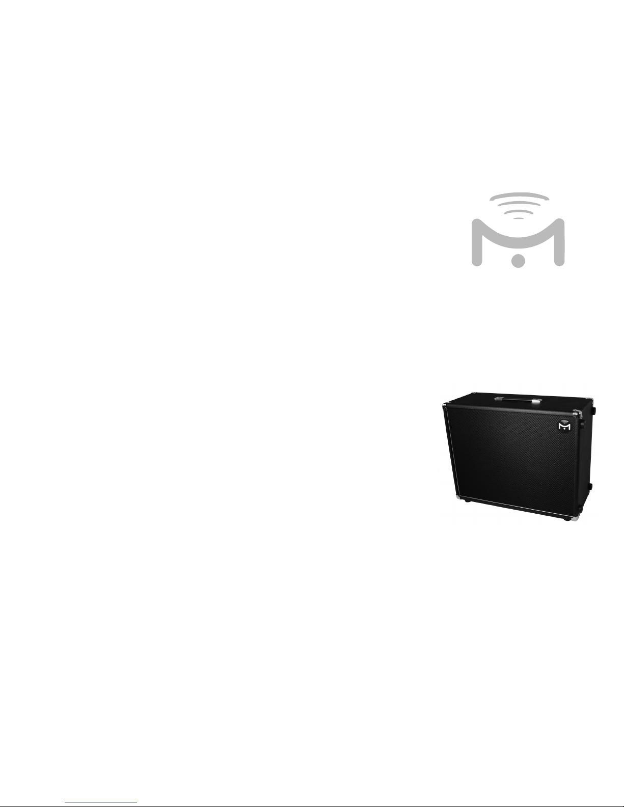
Congratulations on your purchase of the Mission Gemini
2™ (GM-2) stereo amplified guitar speaker. This product is
designed to be intuitive to setup and operate, and to provide
many years of trouble free service. However, we recommend
that you take a few moments to read through this Hardware
User Guide in order to get the best possible experience with
your new speaker.
bAck ound
The GM-2 is a professional quality, stereo amplified speaker
cabinet specifically designed for use with software based
music systems such as guitar modeling amplifiers, cabinet
simulators, and digital audio workstations.
A traditional guitar speaker cabinet is typically designed to
work best in conjunction with a guitar amplifier. The speaker
works within a limited frequency range, and the cabinet and
speaker themselves contribute to the overall tone. While this
works perfectly with an analog guitar rig, it is not always an
ideal solution for digital systems.
Software based modelers usually implement guitar cabinet
simulators designed to emulate specific speaker cabinets
in software. If the signal subsequently passes through a
physical speaker cabinet with its own tonal characteristics, it
colors the eventual tone, making the modeling less accurate.
Additionally, guitar speaker cabinets do not often work well
with signals other than guitar such as keyboards, vocals, and
playing back recorded music. The Mission Gemini amplifiers
and cabinets resolve these problems as they are specifically
designed to work with software based music systems.
k s
The GM-2 is an active speaker cabinet with an internal power
amplifier designed to faithfully reproduce a modeled signal
chain. The cabinet is fitted with 2 x 12” low frequency driver,
and 2 x 1” high frequency compression drivers in a co-axial
configuration: The high frequency driver is mounted in the
center of the low frequency driver.
The Coaxial driver configuration has been used for over sixty
years in professional audio monitoring and high-end audiophile
applications. The benefits include a wider field of dispersion
that’s more uniform across the frequency spectrum. This
means listeners do not have to be positioned directly in front
of the speaker to get the best experience. The full frequency
range also appears to the listener to originate from a single
source, without any apparent physical separation between
low and high frequencies. Since the high frequency driver is
located at the center of the driver, the cabinet can be used
with a microphone, with the high frequencies accentuated
as the microphone is positioned towards the center of the
speaker, replicating the on/off axis positioning of a traditional
guitar cab. These features make the GM-2 ideal for live,
recording, and monitoring use.
Amplifi
The GM-2 includes a 4-channel internal class D amplifier
generating 220W into 8ohms. The amplifier is carefully matched
to the speaker drivers to provide optimum efficiency and
sound pressure levels. The GM-2 operates in stereo mode
using the left and right speakers, or can be bridged into mono
mode.
ConnE ions
There are three inputs and one output on the rear panel of the
GM-2 as follows:
Input 1 – The combo connector supports XLR, ¼” TS or ¼”
TRS jacks. Use a ¼” TRS cable to connect the output from
a line level device such as a modeling amp, preamp, or multi
effects device to Input 1. The right channel is on the tip and
the left channel is on the ring. If your input device outputs left
and right signals on separate jacks, you will need a TRS insert
cable to connect the two output jacks to the single TRS input
jack on the GM-2.
Use an XLR or TS cable to connect a mono signal to Input 1.
When using a mono input, use the stereo/mono toggle switch
to control how the signal is routed to the drivers. In stereo
mode, the signal will use one of the internal drivers. In mono
mode, the mono signal will be bridged to the two sets of
speaker drivers.
Stereo Out – This connector supports ¼” TS cables. If using
two GM-2 systems in a stereo configuration, use a ¼” TRS
(stereo) cable to connect a line level stereo output to Input
1 and a TS (mono) cable to connect the stereo out to the
second GM-2. Switch both systems to mono mode via the
toggle switch. The right stereo channel will be routed to the
second GM-2 system.
When using mono mode, high level input signals may cause
clipping. If this occurs, either reduce the input signal level, or
switch to stereo mode.
Input 2 - This connector supports ¼” TS cables. When using
the USB audio interface on the GM-2, connect your guitar or
other instrument to Input 2. This will allow you to use your
instrument with an audio workstation application such as
Avid® Pro Tools or Apple® Logic ProX, or a software based
modeler such as Scuffham S-Gear. The Gemini audio interface
supports multiple simultaneous streams, so you can, for
example, play along with recorded music on your computer,
or practice with online tutorial
USB – The GM-2 can be connected to a computer using
the USB cable provided. The GM-2 will appear as an audio
interface, and can be used with software based modelers,
and digital audio workstations, as well as to stream audio
from a web browser, audio player etc. Please read the Mission
Gemini Software User Guide for more information
Con o
Level – This controls the output level from the power amplifier
to the speaker drivers. Turn clockwise to increase output level
and counter clockwise to reduce level.
EmPOWER™ – This control allows you to blend the GM-2’s
frequency response between ‘flat’ and ‘cab’ bias. In the flat
position, the cabinet behaves like a studio monitor or Hi-Fi
speaker. This setting is useful when used with cab simulators,
and when using the GM-2 as a monitor for listening to recorded
music or rehearsing with a backing track.
Traditional guitar tube amps and cabs do not typically have
flat frequency response. As a result some people may find
a flat frequency response to be harsh or clinical sounding
compared to a tube amp. Turning the EmPOWER control
counter clockwise modifies the EQ curve for a more typical
guitar cab’s present mids and rolled off highs.
Pow
The GM-2 requires AC wall power to operate. Power is
supplied via an IEC cable to the power connected on the
rear of the unit. The power supply supports 110 – 240 AC
50/60Hz, and so can be used with AC wall supplies in most
countries. Your GM-2 will have been supplied with a power
cable specific for use in your country. Additional international
power cables can be purchased from missionengineering.com.
Depending on country, the power connector maybe fitted
with the V-Lock feature. V-Lock ensures that the power cable
is correctly inserted, and cannot be accidentally removed.
V-Lock cables can be identified by the yellow lock on the
plug. To insert the cable, ensure the power switch is in the
off position and push the plug into the power inlet until the
lock clicks into place. To remove the cable, ensure the power
is switch is in the off position and depress the yellow lock
button. Gently pull the cable from the inlet while holding
down the yellow lock button. In the event a V-Lock cable is
not available, a standard IEC cable can be used. When using
standard cables, the plug will not lock. Replacement V-Lock
cables can be purchased from missionengineering.com.
For safety, the power inlet is fitted with dual fuses. Replace
with 5mm x 20mm 10A fuses. Do not attempt to bypass or
use incorrect fuses. Replacement fuses are available from
missionengineering.com
 Loading...