

Page 1
Guitar Center
Expression Pedal
GC-EXP1
PRO
U r
Guide
ecifi tions
Electrical Specifications
Pedal Potentiometer
Internal resistance - 10K Ohm
Taper - Linear
Polarity - Tip to wiper
Function - Voltage Divider
Usage rating > 1M cycles
Input Trim Potentiometer
Internal resistance - 50K Ohm
Taper - Linear
Function - Limiting
Usage Rating > 15K cycles
Dimensions
Base length at longest point - 9.9”
Base width at widest point - 4.0”
Height at highest point including feet - 3.25”
Pedal length - 8.7”
Pedal width at widest point - 3.0”
Pedal width at narrowest point - 2.3”
Weight - 3.5lbs
Mission Engin ring Inc.
www.mission-engineering.com
info@mission-engineering.com
©
Mission Engineering Inc. 2012. All rights reserved. Trademarks,
registered trademarks, product names, logos and other materials are
the property of their respective owners.
MISSION
ENGINE ING
Sa ty
In ru ions
Read, Keep & Follow these instructions
Heed all warnings
Clean only with dry cloth
Do not use this apparatus near water
Do not expose the apparatus to dripping or
splashing and ensure that no objects filled with
liquids, shall be placed on the apparatus
WARNING: To reduce the risk of fire or electric
shock do not expose this apparatus to rain or
moisture
Unplug this apparatus during lightning storms or
when unused for long periods of time
Do not block any ventilation openings. Install in
accordance with the manufacturer’s instructions
Do not install near any heat sources such
as radiators, heat registers, stoves, or other
apparatus (including amplifiers) that produce
heat
Only use attachments/accessories specified by
the manufacturer
Prolonged listening at high volume levels may
cause irreparable hearing loss and/or damage.
Always be sure to practice “safe listening.”
Refer all servicing to qualified service personnel.
Service is required when the apparatus has been
damaged in any way, such as:
- power-supply cord or plug is damaged
- liquid has been spilled or objects have fallen
into the apparatus
- the unit has been exposed to rain or moisture.
- the unit is dropped or the enclosure is
damaged
- the unit does not operate normally or changes
in performance in a significant way
Page 2
In odu ion
Congratulations on your purchase of the Guitar
Center GC-EXP1-PRO Expression Pedal. This product
is designed to be intuitive to set-up and operate, and
to provide many years of trouble free service.
However, we recommend that you take a few
moments to read through this User Guide in order
to get the best possible experience with your new
pedal.
Expression pedals are intended to remotely control
functions of other devices such as digital guitar
amps, multi-effect rack units, effects pedals, MIDI
controllers, and electronic keyboards. Expression
pedals do not generate sounds themselves, but allow
the musician to remotely control effects and
parameters within other equipment. Be sure to check
the specifications of the device you will be
controlling in order to ensure compatibility. The
specifications for the GC-EXP1-PRO are listed on the
reverse of this User Guide.
A regularly updated compatibility list is maintained
on the support section at
www.mission-engineering.com
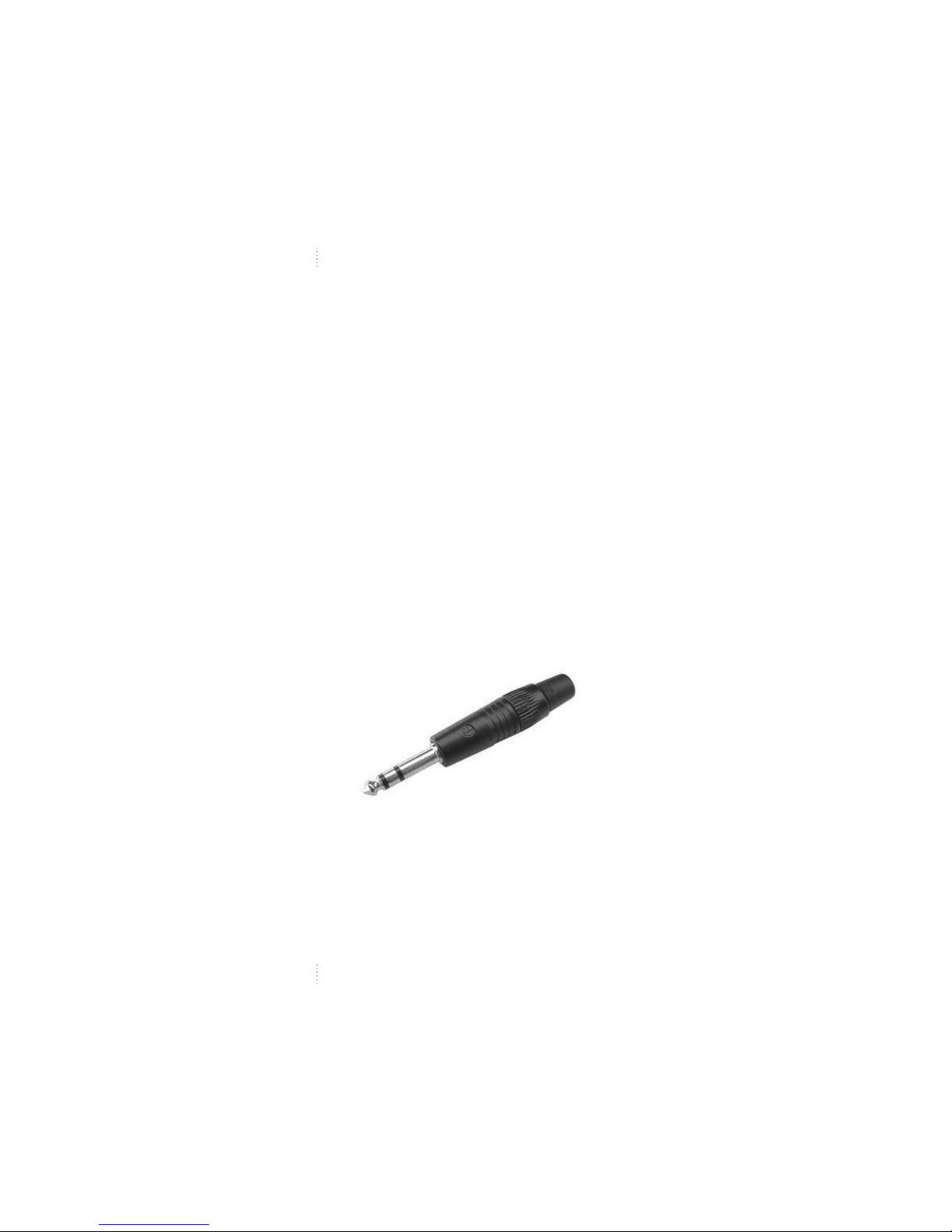
Conne ions
The GC-EXP1-PRO uses a single ¼” TRS phone plug
output marked OUT1 on the underside of the pedal.
OUT2 is not used in this pedal model, and can be
ignored. OUT2 is fitted with a blank.
Connect OUT1 to the expression pedal input on your
device using a ¼” TRS-TRS instrument cable such
as the Mission MCTRS3A cable. TRS stands for
Tip, Ring, Sleeve and is a three conductor cable. It
is sometimes also called a stereo, or balanced cable.
(See Figure 1.) The GC-EXP1-PRO requires the use of
the correct cable with a TRS connector at both ends.
A mono TS cable such as a regular guitar cable, and
insert cables that have both TS and TRS plugs, will
not work.
Figure 1. shows a TRS connector with the three
conductors separated by the black insulation bands.
The pointed front of the connector is the tip, the
middle band is the ring, and the large conductor at
the rear nearest the plug body is the sleeve.
The silver knob on the right side of the pedal is
marked INPUT. This controls the minimum input
level of the pedal. The control acts as a trim pot and
sets the minimum level for the pedal at heel down.
With the control fully counter clockwise, the pedal
will be 0% at heel down and 100% at toe down.
Adjust the INPUT control clockwise to increase the
heel down value above 0%.
For example, maybe you are using the expression
pedal to control volume on an amp or keyboard.
Let’s say you want maximum volume with the pedal
all the way at toe down, but you would like to set
the volume at heel down to 50% rather than all the
way off. Turn the control to about halfway.
This will set the minimum to about 50% and the
pedal will now sweep 50 – 100%.
The INPUT control will adjust the minimum level
between 0 and approximately 80%. The control has
no impact on the maximum value, which will always
be 100% at toe down.
Figure 1.
 Loading...