


IMPORTANT SAFETY INSTRUCTIONS
WARNING
1. Read these instructions.
2. Keep these instructions.
3. Heed all warnings.
4. Follow all instructions.
5. Do not use this apparatus near water.
6. Clean only with a dry cloth.
7. Do not block any ventilation openings. Install in accordance with the manufacturer's
instructions.
8. Do not install near any heat sources such as radiators, heat registers, stoves, or other
apparatus (including amplifiers) that produce heat.
9. Do not defeat the safety purpose of the polarised or ground plug: A polarised plug has
two blades with one wider than the other. The wide blade is provided for your safety.
When the provided plug does not fit into your outlet, consult an electrician for
replacement of the obsolete outlet.
10. Protect the power cord from being walked on or pinched particularly at plug,
convenience receptacles, and the point where they exit from the apparatus.
11. Only use attachments/accessories specified by the manufacturer.
12. Use only with a cart, stand, tripod, bracket, or table specified by the
manufacturer, or sold with the apparatus. When a cart is used, use
caution when moving the cart/apparatus combination to avoid injury
from tip-over.
13. Unplug this apparatus during lightning storms or when unused for
long periods of time.
14. Refer all servicing to qualified service personnel. Servicing is required when the
apparatus has been damaged in any way, such as power-supply cord or plug is
damaged, liquid has been spilled or objects have fallen into the apparatus, the
apparatus has been exposed to rain or moisture, does not operate normally, or has
been dropped.
15. To reduce the risk of fire or electric shock, do not expose this apparatus to rain or
moisture.
16. Apparatus should not be exposed to dripping or splashing and no objects filled with
liquids, should be placed on the apparatus.
17. Use only with the battery which specified by manufacturer.
1. FOR OUTDOOR USE:
To reduce the risk of fire or electric shock, do not expose this apparatus to rain or
moisture.
2. UNDER WET LOCATION:
Apparatus should not be exposed to dripping or splashing and no objects filled with
liquids, such as vases should be placed on the apparatus.
3. SERVICE INSTRUCTIONS:
CAUTION - These servicing instructions are for use by qualified service personnel only. To
reduce the risk of electric shock, do not perform any servicing other than that contained
in the operating instructions unless you are qualified to do so.
This symbol indicates that dangerous voltage constituting a risk of electric shock
is present within this unit.
This symbol indicates that there are important operating and maintenance
instructions in the literature accompanying this unit.
& IC - ID
THIS DEVICE COMPLIES WITH PART15, PART74 OF THE FCC RULES AND RSS-210
ISSUE8 OF CANADA. OPERATION IS SUBJECT TO THE FOLLOWING TWO
CONDITIONS:
(1) This device may not cause interference.
(2) This device must accept any interference, including interference that may cause
undesired operation of the device. This equipment complies with FCC RF radiation exposure
limits set forth for an uncontrolled environment.
“This product can only be used at the area that the altitude is lower than 2000m for safety
purpose.”
“This product can be used in non-tropical locations only for safety purpose.”
18. The power supply cord set is to be the mains disconnected device.
19. Batter Pack shall not be exposed to excessive heat such as sunshine fire or the like.
20. In Finland, Norway and Sweden, CLASS I apparatus which is intended for connection to
the building installation wiring via a plug or an appliance coupler, have a marking
stating that the apparatus must be connected to an earthed MAINS socket-outlet.
21. A warning that an apparatus with CLASS I construction shall be connected to a MAINS
socket outlet with a protective earthing connection.
,
Disposal
2005-08-13
Dispose of any unusable devices or batteries responsibly and in accordance
with any applicable regulations.
Disposing of used batteries with domestic waste is to be avoided!
Batteries/NiCad cells often contain heavy metals such as cadmium(Cd),
mercury(Hg) and lead(Pb) that makes them unsuitable for disposal with
domestic waste. You may return spent batteries/accumulators free of charge
to recycling centres or anywhere else batteries/accumulators are sold.
By doing so, you contribute to the conservation of our environment!

PORTABLE WIRELESS PA SYSTEM PORTABLE WIRELESS PA SYSTEM
Federal Communication Commission Interference Statement
This equipment has been tested and found to comply with the limits for a Class B digital
device, pursuant to Part 15 of the FCC Rules. These limits are designed to provide
reasonable protection against harmful interference in a residential installation.
This equipment generates, uses and can radiate radio frequency energy and, if not installed
and used in accordance with the instructions, may cause harmful interference to radio
communications. However, there is no guarantee that interference will not occur in a
particular installation. If this equipment does cause harmful interference to radio or television
reception, which can be determined by turning the equipment off and on, the user is
encouraged to try to correct the interference by one of the following measures:
! Reorient or relocate the receiving antenna.
! Increase the separation between the equipment and receiver.
! Connect the equipment into an outlet on a circuit different from that to which the receiver
is connected.
! Consult the dealer or an experienced radio/TV technician for help.
!
FCC Caution: To assure continued compliance, any changes or modifications not expressly
approved by the party responsible for compliance could void the user's authority to operate
this equipment. (Example - use only shielded interface cables when connecting to computer
or peripheral devices).
CONTENTS
CONTROLS AND INDICATORS
CONTROL PANEL ---
------------------------------------------------------------ 05
PAIRING BLUETOOTH MUSIC RECEIVER -
OPERATING INSTRUCTIONS --
CONNECTION FOR EXTERNAL AUDIO SOURCES
POWER USAGE INSTRUCTION
REPLACING RECHARGEABLE BATTERIES
MRM-70B: UHF DIVERSITY RECEIVER MODULE
WIRELESS TRANSMITTER MODULE
DPM-3
DIGITAL AUDIO RECORDER MODULE --------------------------------- 16
INSTALLATION OF MIPRO CD/MP3 PLAYER
------------------------------------------------- 02
------------------------------------- 07
------------------------------------------------- 09
----------------------------- 10
------------------------------------------------- 11
------------------------------------- 13
----------------------------- 14
------------------------------------------- 15
----------------------------------- 26
FCC Radiation Exposure Statement
This equipment complies with FCC RF radiation exposure limits set forth for an uncontrolled
environment. This equipment should be installed and operated with a minimum distance of
20 centimeters between the radiator and your body.
This transmitter must not be co-located or operating in conjunction with any other antenna
or transmitter.
The antennas used for this transmitter must be installed to provide a separation distance of
at least 20 cm from all persons and must not be co-located or operating in conjunction with
any other antenna or transmitter.
THIS DEVICE COMPLIES WITH PART 74 AND PART 15 OF THE FCC RULES. This equipment
complies with
This device complies with Industry Canada licence-exempt RSS-210 ISSUE 8 standard.
Operation is subject to the following two conditions: (1) this device may not cause
interference, and (2) this device must accept any interference, including interference that
may cause undesired operation of the device.
FCC RF radiation exposure limits set forth for an uncontrolled environment.
HELPFUL OPERATING TIPS
TROUBLESHOOTING-PORTABLE PUBLIC ADDRESS 28
TROUBLESHOOTING-WIRELESS MICROPHONE SYSTEMS -- 29
FAQ - PORTABLE PA 30
------------------------------------------------------------
FAQ - RECHARGEABLE BATTERY -- 31
RECHARGEABLE BATTERY GUIDE -------- 32
OPTIONAL MA-505 ACCESSORIES 33
----------------------------------------------------- 27
---------------------------
------------------
--------------------------------------------
-------------------------------------
--------------------------------------------
Le présent appareil est conforme aux CNR d'Industrie Canada applicables aux appareils radio
exempts de licence. L'exploitation est autorisée aux deux conditions suivantes : (1)
l'appareil ne doit pas produire de brouillage, et (2) l'utilisateur de l'appareil doit accepter
tout brouillage radioélectrique subi, même si le brouillage est susceptible d'en compromettre
le fonctionnement.
00
01
PORTABLE WIRELESS PA SYSTEM PORTABLE WIRELESS PA SYSTEM
CONTROLS AND INDICATORS
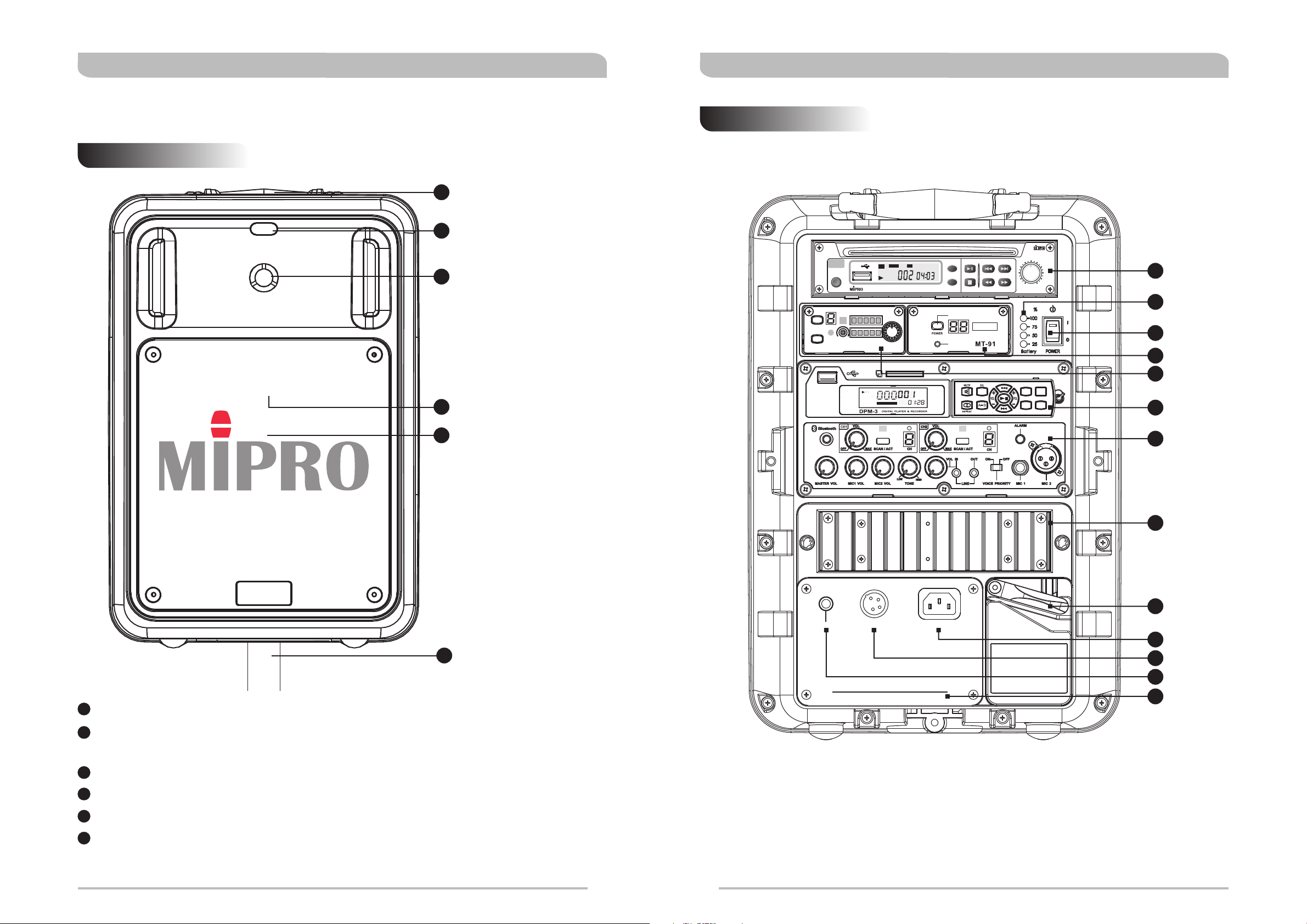
Front Panel
1
Fixed Handle
2
Remote Control Port
3
Treble Speaker
4
Bass Speaker
Rear Panel
COMPACT
VIDEO
DIGITAL
EJECT
PLAY/PAUSE NEXT
ALL
USB
POWER
NOISE
NOISE
CHANNEL
CHANNEL
SCAN
SCAN
-
+
ACT
ACT
SENSITIVITY
SENSITIVITY
REPEAT
MP3
COMPACT DISC PLAYER
RF
RF
VOLUME
VOLUME
AF
AF
REPEAT
CHANNEL
LEVEL LIMIT
PREV.
STOP
BAND
LEVEL
7
+
-
F.FWDF.BWD
8
9
10
11
PROG
M
USB A B
REP ALL
FOLDER
SD
RAN
12
5
Speaker Grille
MA-505
6
Tripod Mount
1
Fixed Handle: For balanced, easy hand carrying.
2
Remote Control Port: Aim external remote control from the front to remotely
control the digital music player.
13
14
15
AC 100~240VDC 24~28VEXT. SPKR
16
17
18
19
3
Treble Speaker: 1" Titanium Compression Driver.
4
Bass Speaker: 8" speaker.
5
Speaker Grille: To protect the internal speaker.
6
Tripod Mount (Optional): There is a tripod mating socket mounted in the
base of the MA-505 to accommodate a 35mm tripod stand.
02
03
PORTABLE WIRELESS PA SYSTEM PORTABLE WIRELESS PA SYSTEM
7
Skip-free (Optional)
8
Battery Meter: Displays current & charging battery level.
CD/MP3 PLAYER
Blinking (charging in progress); Illuminated (battery is fully charged)
9
Master Power Switch: Turns AC/DC power on/off to the unit. The indicator
glows when you turn the power On. To avoid over-discharging or stressing of
the built-in battery supply, it is recommended that you plug-in and charge the
unit immediately when LED indicator flashes (denotes lower battery status).
Otherwise, the unit will turn off automatically once a pre determined low charge
level is reached as it may interrupt the performances. A full recharge may take
up to 4 hours. When fully charged, make sure to turn the power OFF to
conserve battery power and when not being used.
10
MT-91 Wireless Transmitter Module
11
MRM-70B
12
DPM-3
13
Control Panel
14
Heat Sink: Built in heat sink for amplifier. Keep the unit well ventilated when in
Receiver Modules (Optional)
Digital Audio Recorder Module
(Optional)
use and please do not touch the heat sink when in operation.
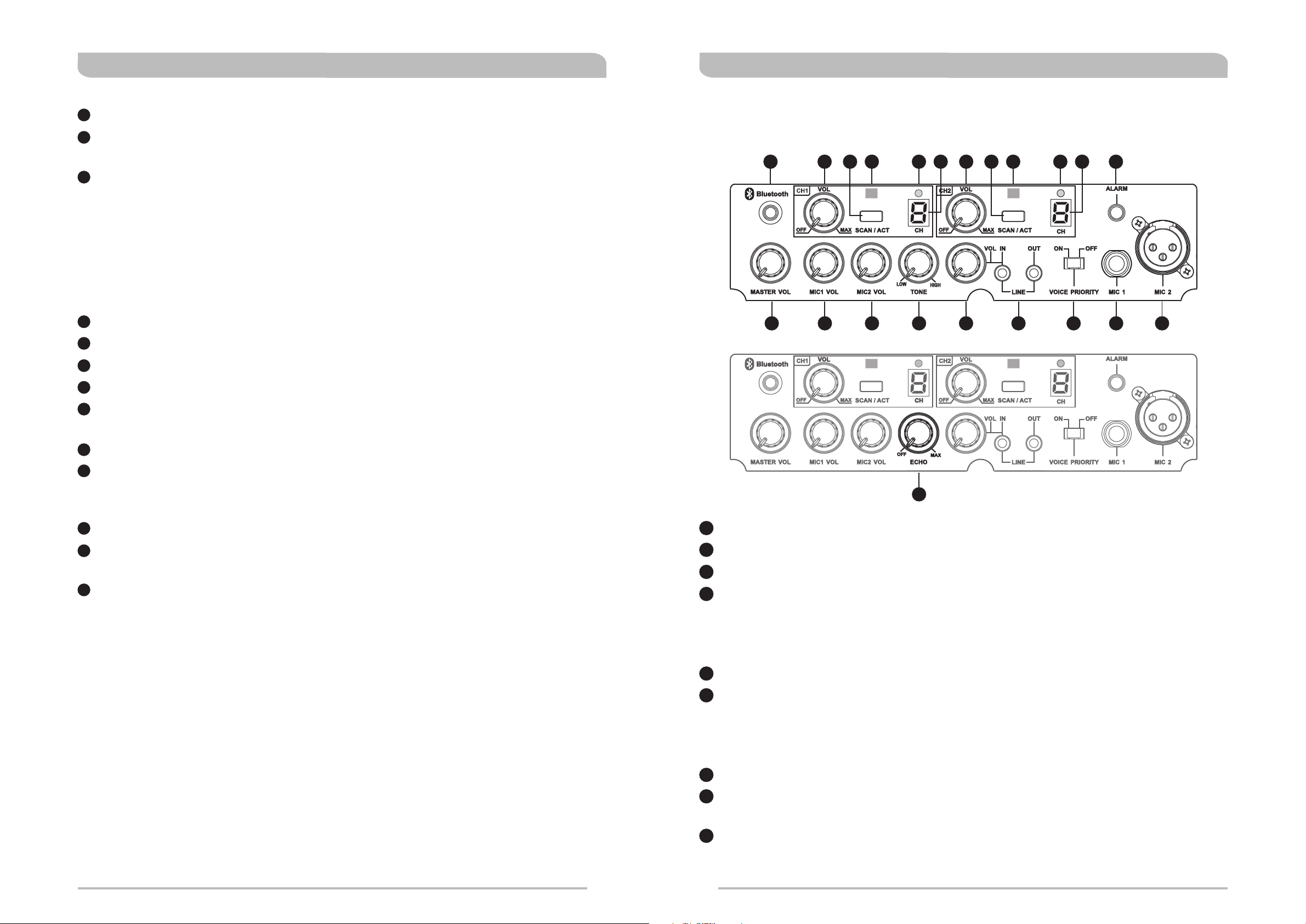
CONTROL PANEL
B20
B1 B2 B3
B4
B11B12B13B14B15B16B17B18B19B21 B10
B5 B6 B7 B8 B9
15
Storage Lever: Adjust lever to keep storage lid tightly.
16
AC Power Input Socket (AC 100~240V): Input socket for AC Power
(100~240V). (Various outlets fitting the standards of various countries are
available for this unit)
17
DC Input Jack (DC 24~28V): Requires external DC 24~28volts.
18
Extension Speaker Input Jack (EXT. SPKR): Accepts output from the
EXT. SPKR Jack of MA-505.
19
Battery Cover: Protects the rechargeable battery.
B4
B1
MASTER Volume Control: Adjust the volume of all mixed audio inputs.
B2
MIC 1 Volume Control : Control the volume of the Mic 1 wired microphone.
B3
MIC 2 Volume Control: Control the volume of the Mic 2 wired microphone.
B4
TONE Control (varies by region): Turn counterclockwise to increase bass or
turn clockwise to increase treble. Positioned at 12 o'clock for a flat response.
ECHO Control (varies by region): Adjust for desired ECHO effects. (chose
one of two)
B5
LINE IN Volume Control: Controls the volume of the Line Socket.
B6
LINE IN Socket (3.5mm mono): Allows you use an external device with
unbalanced audio output signal as an input to the MA-505.
LINE OUT Socket (3.5mm mono): Line level output. Allows you to use the
MA-505 as a program input source for some other audio device.
04
B7
Voice Priority Switch: Voice over music priority function. (factory preset: Off)
B8
Wired Microphone Input Socket (6.3mm/ 1/4” Unbalanced): Allows you
to use an unbalanced, wired microphone as an input source.
B9
Wired Microphone Input Socket (XLR Balanced): Allows you to use wired
microphone with a balanced XLR connector as an input source.
05

PORTABLE WIRELESS PA SYSTEM PORTABLE WIRELESS PA SYSTEM
B10
Alarm Siren Button: Provide warning of approaching or presence of threats or
situations requiring immediate attention.
B11
CH2 Channel Screen
B12
CH2 RF indicator: Glows green indicates a RF link from transmitter to receiver.
B13
CH2 Sync port: Uploads infrared signal to transmitter.
B14
SCAN/ACT CH2: Scans for an interference-free frequency & Synchronizes the
receiver and transmitter frequencies.
B15
CH2 VOL: Powers receiver on/off and wireless CH2 volume.
B16
CH1 Channel Screen
B17
CH1 RF indicator: Glows green indicates a RF link from transmitter to receiver.
B18
CH1 Sync port: Uploads infrared signal to transmitter.
B19
SCAN/ACT CH1: Scans for an interference-free frequency & Synchronizes the
receiver and transmitter frequencies.
B20
CH1 VOL: Powers receiver on/off and wireless CH1 volume.
B21
Bluetooth Power Button & Indictor: The built-in Bluetooth music receiver
lets you connect a Bluetooth-enabled wireless device such as an iPod, iPhone,
iPad or other smart phones, tablets, media players and play music wirelessly
through this portable PA system.
PAIRING BLUETOOTH MUSIC RECEIVER
! Make sure the built-in Bluetooth music receiver is powered on and bring the
wireless device within reception range.
! To power on the Bluetooth music receiver and ready for pairing, press & hold
the power button for 3-5 seconds until blue/red indicator light is flashing
intermittently.
! The blue/red flashing will flash intermittently to indicate the unit is powered and
is now ready to be paired to your Bluetooth smart wireless device. However, if
blue/red is not flashing intermittently this indicates the unit is not powered and
is not ready to be paired.
! Navigate to the Bluetooth Manager on the wireless device. Locate and enable
the Bluetooth feature.
! Search Bluetooth devices for the music receiver's ID. The device ID is the word
‘MIPRO MB-XX’ and followed by two numbers for the two XXs. Click on the
device ID.
! Enter "0000" when you're prompted to enter a PIN number. This will cause your
wireless device to pair with the music receiver.
! Once paired and connection is made, the blue color indicator light on the music
player will continue to flash intermittently.
! Reconnect to music receiver after moving your wireless device out of its range,
lost signal, objects are blocking the Bluetooth signal or after turning off the
Bluetooth feature on your wireless device. Navigate to the Bluetooth Manager,
and click on the correct device ID. You won't be prompted to enter the PIN
number, 0000, again.
! Pair another wireless device. Navigate to the Bluetooth Manager on the
currently-connected device and disable the Bluetooth function. Follow the Pairing
on the new Bluetooth device to connect the new device.
! To power off the Bluetooth music receiver, press & hold the power button for
3-5 seconds until blue/red indicator light is turned off and no longer flashing
intermittently.
06
07

PORTABLE WIRELESS PA SYSTEM PORTABLE WIRELESS PA SYSTEM
PAIRING BLUETOOTH MUSIC RECEIVER
Tips & Warning
!
After pairing, some devices will connect immediately. Others will ask you if you
want to connect.
!
If you move the wireless device out of the Music Receiver's range, the
connection will be lost and the indicator light will go off. If you move the
wireless device back into range, the connection will re-establish itself.
!
The Bluetooth music player can only play music from one device at a time.
!
Clean only with a dry cloth.
!
Do not expose the device to rain, use it near water or in damp or wet
conditions, or place containers on it containing liquids which might spill into any
openings.
OPERATING INSTRUCTIONS
Wired Microphone
!
Plug optional MIPRO MM-107 wired dynamic microphone with a 6.3mm (1/4”)
connector to MIC IN.
!
Turn on master POWER and adjust to desired volume.
Line Input
!
Available to connect an external CD, MP3, iPod or cassette player.
!
Connect a 3.5mm(mono)-to-3.5mm(stereo) audio cable (not included) to the
LINE-IN jack.
!
Turn on master POWER.
!
Adjust LINE VOL to desired volume.
Alarm Siren
!
Press Alarm button for warnings of approaching or presence of threats or
situations requiring immediate attention. This is an ascending sound of an
alarm.
OPERATING INSTRUCTIONS
Wireless Mic System
!
Turn on master Power switch. Power indicator glows red. Ready for operation.
!
Turn on CH1 VOL or CH2 VOL switch.
!
Turn transmitter power on. Ensure fresh alkaline or lithium batteries (not
included) are installed.
!
CH1 RF indicator or CH2 RF indicator glows green after the transmitter is
turned on to denote a successful RF link.
!
Adjust CH1 VOL or CH2 VOL to desired volume.
!
Ensure receiver and transmitter have the same matching operating channels.
Notes:
1. Same wireless microphone can transmit to multiple MA-505 systems on the
same channel for a wider and expanded coverage.
2. It is not possible to transmit two wireless microphones on the same channel
to MA-505 system. Only one transmitter can be used at a time on that
channel. Be sure to turn off one of the two transmitters to avoid
interference.
!
Alarm will sound only when master Power is powered on and one of below
function is powered on.
1. Wireless transmitter and CH1 or CH2 are powered on.
2. Wired microphone is plugged into the Mic input and powered on.
3. USB player is powered on & music is playing.
08
09

PORTABLE WIRELESS PA SYSTEM PORTABLE WIRELESS PA SYSTEM
CONNECTION FOR EXTERNAL AUDIO SOURCES POWER USAGE INSTRUCTION
General Summary
! A built-in switching power supply allows for AC power inputs ranging from
100~240volt and an external 24~28 volt DC power supply, is required.
! A built-in AC power supply powers the unit itself and provides recharging to the
built-in rechargeable batteries, too.
How to use AC power input
! After putting the power plug into the AC input socket of the device, the 4
battery meter indicators will glow immediately, no matter if the power switch is
on or off. This means that the built-in switching power supply is functioning
MP3 PLAYER
Mi xe r
Am pl ifi er
I-PODCD PLAYER
Cassette Recorder
Cable Microphone (XLR)
Cable no: 2FA030
Cable Microphone (Phone-Jack)
Cable no: 2FA031
normally and the built-in rechargeable batteries are fully charged. If the battery
meter indicators are blinking this means that the built-in switching power supply
is working normally and the built-in rechargeable batteries are in an under
charged condition. After a couple of minutes, the battery meter indicators will
stop blinking and continue a glowing condition, indicating the batteries are now
fully charged.
! AC power provides power to both the unit itself and to the built-in rechargeable
batteries.
! When using the AC power, you can remove or plug the power cord freely with
no need to turn off the power switch first. If or when an unfortunate power cut
happens during usage, the unit will activate the DC power automatically to
maintain continuous operation.
How to use DC power input
! Built-in rechargeable batteries are used. When the batteries are fully charged,
the unit can be operated for approximately 8 hours in standby mode. Playing
the music loudly will drain the rechargeable batteries down faster. (The above
figures are references for brand new, fresh batteries only)
! The built-in rechargeable batteries can be recharged when the unit is plugged
into an AC or DC power outlet.
! The red power indictor will glow when power switch is turned on. Additionally, 2
to 4 battery meter indicators are glowing to indicate normal operation mode.
! If only 1 battery meter indicator is glowing this indicates low battery status
therefore, it is highly recommended to plug-in for recharging and it can be
operated while charging.
10
! If no battery meter indicator is glowing after the unit is turned on, it indicates
the batteries are completely discharged or possibly faulty batteries.
11

PORTABLE WIRELESS PA SYSTEM PORTABLE WIRELESS PA SYSTEM
! Always store the system with the batteries fully charged if needing to store the
system for more than 3 months. Leave the system plugged into an AC power
outlet when not in use or recharge once at least every 3 months.
! The rechargeable batteries will not function properly if not recharged for an
extended period of time. It is therefore, recommended to recharge after every
use regardless of the usage time to preserve battery life.
AC power and DC power can not be used at the same time.
A connector is included which allows users to make DC wiring. See diagram below
for illustration:
Connector
4
1
2
3
DC JACK Diagram
4
3
2
1
DC V: 24~28V/10A
_
DC V
+
REPLACING RECHARGEABLE BATTERIES
! The batteries must be replaced every 2~3 years depending on usage over
time and limited amount of charge cycles.
! Ascertain the power switch is turned off and AC cord is unplugged.
1. Using a Phillips-head screwdriver (not supplied) remove the screws.
(Figure 2-1)
2. Remove the battery protection cover panel. (Figure 2-2)
3. To remove batteries, gently detach and slide the battery away from the
battery housing compartment horizontally. (Figure 2-3)
4. Replace batteries “as above” and re-connect the wires to the new batteries
horizontally in accordance to the wiring diagram below. (Figure 2-4)
5. Replace the battery protection cover panel, tighten up the screws.
(Figure 2-5)
(Figure 2-2) (Figure 2-1)
Storing Power Plug & Cable
! Adjust lever to remove the lid plate (Figure 1-1)
! Insert into the storage (Figure 1-2)
! Adjust lever to close the lid plate tightly (Figure 1-3)
(Figure 1-1) (Figure 1-2) (Figure 1-3)
12
(Figure 2-3)
(Figure 2-4)
13
(Figure 2-5)
CAUTION
Danger of explosion if battery is incorrectly
replaced.
Replace only with the same or equivalent type.

PORTABLE WIRELESS PA SYSTEM PORTABLE WIRELESS PA SYSTEM
MRM-70B: UHF DIVERSITY RECEIVER MODULE
MIPRO offers an optional industry-leading diversity wireless receiver module. Up to 2
receiver modules can be installed quickly and easily for wireless microphone
operation. Each receiver module has 16 preset UHF frequencies. Simply press the
“scan” button once to quickly autoscan for an interference-free receiver frequency. A
built-in “noise” interference indicator (when lit) detects the presence of interference.
Once lit during operation simply press scan button to autoscan for another
interference-free frequency.
INSTALLING MRM-70B DIVERSITY RECEIVER MODULE
Up to 2 MRM-70B receivers can be installed or o1 MRM-70B or 1 MT-91 interlinking
transmitter can be installed.
1. Power off the system first.
2. Remove the 2 screws. ( 3-1)
3. Remove the front blank plate. ( 3-2)
Figure
Figure
WIRELESS TRANSMITTER MODULE
INSTALLATION OF WIRELESS INTERLINKING TRANSMITTER
1. Remove screws from blank panel. (Figure 4-1)
2. Remove blank panel. (Figure 4-2)
3. Insert the Interlinking Transmitter module horizontally. (Figure 4-3)
4. Gently push in until it is aligned into place. (Figure 4-4)
5. Tighten the screws. (Figure 4-5)
(Figure 4-2)(Figure 4-1) (Figure 4-3)
(Figure 4-4) (Figure 4-5)
4. Insert the receiver module. ( 3-3)
5. Push in and align the edge connectors firmly and tightly. ( 3-4)
6. Fasten the screws tightly. ( 3-5)
(Figure 3-1)
Figure
Figure
(Figure 3-2)
Figure
(Figure 3-3)
(Figure 3-4) (Figure 3-5)
Operating Tips
1. The transmitter functions when the module and antenna are inserted properly
and powered on. Ascertain the frequency code sticker is the same between the
transmitter and receiver.
2. Select another module with a different frequency code if the existing operating
frequency experiences continuous interference.
3. MT-91 module is available in frequency codes between 620~934MHz and
compatible with MIPRO wireless receivers or portable PA amplifiers with the
same frequency codes.
Use 2 different frequency codes
TX MIC MT-91
RX
14
15
NOISE
SCAN
CHANNEL
-
ACT
SENSITIVITY
RF
+
VOLUME
AF
8A Frequency Code
CHANNEL
LEVEL LIMIT
BAND
7A Frequency Code

PORTABLE WIRELESS PA SYSTEM PORTABLE WIRELESS PA SYSTEM
DPM-3 DIGITAL AUDIO RECORDER MODULE
Control and Indicators
F6
USB A B
REP ALL
FOLDER
F1
VFD DISPLAY SCREEN: Displays parameters such as elapsed time, tracks,
repeat…etc.
F2
IR (Infrared) RECEIVER SENSOR WINDOW: Aim towards this section to
maximize signal reception quality when using the detachable Remote Control.
F3
ON-BOARD CONTROL PANEL & REMOTE CONTOL (Detachable): Sets
functions with Control Panel or wirelessly via Remote Control.
F4
REMOTE CONTROL LATCH: Turn latch to the right to release the Remote
Control.
F5
SD CARD SLOT: Supports SD/SDHC memory card and up to 32GB capacity.
Insert a SD memory card (labeled side left) and push into the slot.
F5
PROG
M
SD
RAN
F1 F2 F3
F4
Front Panel of Remote Control
F15
F18
F20
F19
F7
POWER :POWER On/Off
F8
SOURCE Mode :Select USB or SD Card source
F9
REC :RECORD
F10
STOP
F11
FOLDER + - :Folder up or down change
F12
PLAY :PLAY or PAUSE
F13
F14
F16
F17
F7
F8
F13
F9
F11F14
F10
:Previous track or press & hold for fast previous track
:Next track or press & hold for fast forward track
F25
F23
F24F12
F21
F22
F6
USB PORT: Supports MP3, WAV and WMA format music and audio files.
Reading the Display Screen
PROG
SD
USB A B
M
RAN
REP ALL
FOLDER
Play :Current track playing
Pause :Current track paused
USB or SD :USB or SD Card
playing source
REP :Repeat Current Track
REP ALL :Repeat All Tracks
REP FOLDER :Repeat Current Folder
RAN :Random Play
A B :A B Repeat
:Folder Display
:Playing Track
:Elapse Time
:Volume Indicator
16
F15
VOL + - :Raises or Lowers volume
F16
EQ :Equalizer
F17
F18
F19
F20
F21
A B :Playing back a specified section repeatedly (A B Repeat)
MUTE :Mute audio
REPEAT :Repeat audio
Detachable IR (Infrared) Remote
NEXT :Fast-Forward 3 seconds. Press & hold for continuous
fast-forward of current track.
F22
PREV :Fast-Rewind 3 seconds. Press & hold for continuous
fast-rewind of current track.
F23
RAN :Plays tracks randomly.
F24
DEL :Deletes MP3 playback or recorded track.
F25
Number buttons :0~9 for track selection.
17

PORTABLE WIRELESS PA SYSTEM PORTABLE WIRELESS PA SYSTEM
REPLACING THE REMOTE CONTROL BATTERY
This remote control uses a CR2032 lithium coin battery that is commonly by in small
electronic devices and easy to replace. You'll find these batteries at most electronics,
supermarkets and at drug stores. Replace with a new, fresh CR2032 when the
remote's battery power is low or remote control starts to work erratically.
!
Press and hold both sides of battery compartment. Pull the battery
compartment out and remove the battery (pictured below).
!
Insert a replacement CR2032 lithium battery with the positive (+) side facing
up.
!
Gently slide the battery compartment closed. It locks automatically
OPERATION FUNCTIONS
Power On:
! ON and Volume Indicator are displayed.
PROG
SD
USB A B
REP ALL
FOLDER
Media Slots:
! USB Disk: Insert USB into the USB port.
! SD Card Reader: Insert a SD card with gold contacts facing up and label facing
down.
M
RAN
BATTERY WARNINGS
! Keep the remote control battery away from children. It may cause a fire or
chemical burn if mishandled.
! Do not recharge, disassemble, heat above 212° F (100° C), or incinerate.
! Dispose of batteries according to local regulations. Please recycle when possible.
! Do not dispose as household waste or in a fire as they may explode.
! Replace only with CR2032 lithium battery.
! Replace only with a battery of the correct type and model number.
! Format USB and SD card before playback. Format standard is FAT.
USB SD
PROG
M
USB A B
REP ALL
FOLDER
SD
RAN
Media Source Selection:
! Once a USB or SD card is inserted, it detects media source automatically and
playback starts.
PROG
SD
M
RAN
SD Card
USB
USB A B
REP ALL
FOLDER
18
19

PORTABLE WIRELESS PA SYSTEM PORTABLE WIRELESS PA SYSTEM
Nod (NO DISK) displays when it is unable to detect or read a media source.
PROG
SD
USB A B
M
RAN
REP ALL
FOLDER
STOP: Playback is stopped
PROG
SD
USB A B
M
RAN
REP ALL
FOLDER
Fast Forward:
! NEX appears when pressed.
! Track Time will be fast forwarded.
! Playback starts when button is released.
USB A B
REP ALL
FOLDER
Fast Rewind:
! BCK appears when pressed.
! Track Time will be fast rewinded.
! Playback starts when button is released.
PROG
SD
M
RAN
PLAYBACK: Normal playback display.
USB A B
REP ALL
FOLDER
PAUSE: Paused display
PROG
SD
M
RAN
PROG
SD
USB A B
M
RAN
REP ALL
FOLDER
Volume Indicator: 0 to 15
! Press once + to increase and – to decrease volume.
! Press and hold to increase and decrease incrementally.
! VOL & numeric volume loudness display appears for approximately 2 seconds
during operation.
PROG
SD
USB A B
M
RAN
REP ALL
FOLDER
USB A B
REP ALL
FOLDER
PROG
SD
M
RAN
20
SKIP:
! Press to skip to next or previous track.
21

PORTABLE WIRELESS PA SYSTEM PORTABLE WIRELESS PA SYSTEM
FOL (Folder):
! Press to skip to next or previous folder.
! If both USB and SD care are both plugged when FOL + or - is
pressed it will not skip to next or previous folder, instead it jumps
USB to/from SD card alternatively.
Music Playback:
! Press PLAY for playback. Folder and track will be displayed.
! Press PLAY again during playback to pause. Press PLAY again to resume
playback.
! Press STOP to stop playback.
Two optoins for the order of playing music:
! Copy the desired songs into USB storage unit one by one until copying all the
desired songs. By this way, the play sequency will be based upon the order of
music being programed into USB storage unit.
A→B Repeat:
! Press A B once to specify the starting point of A-B repeat. A appears
! Press A B once to specify the starting point of A-B repeat. A appears
! Press A B again to specify the ending point of the A-B repeat. B appears
! A B Repeat starts automatically and repeatedly.
! To cancel, press A B again.
USB A B
PROG
SD
M
RAN
REP ALL
FOLDER
PROG
SD
USB A B
M
RAN
REP ALL
FOLDER
! If the desired songs will be divided into different folders, please number the
songs when copying them into folders then copying the said folders into USB
storage unit. Pleae note the songs must be numbered by the same digit like 00,
01, 02 or 000, 001, 002 or 0000, 0001, 0002.. and so on.
Repeat Playback:
! Press REPEAT to select one of the repeat options.
! No display: No repeat of any track.
! REP: Repeat same track.
! REP ALL: Repeat all tracks.
! REP FOLDER: Repeat folder.
不顯示 REP REP ALL REP FOLDER
USB A B USB A B USB A B
REP ALL REP ALL REP ALL
FOLDER FOLDER FOLDER
USB A B
REP ALL
FOLDER
EQ (equalization):
! Press EQ for one of the 7 equalization effects: NOR ROC POP CLA SOF
JAZ BAS.
NOR: Normal
ROC: Rock
POP: Popular
CLA: Classic
SOF: Soft
JAZ: Jazz
BAS: Bass
PROG
SD
USB A B
M
RAN
REP ALL
FOLDER
22
23

PORTABLE WIRELESS PA SYSTEM PORTABLE WIRELESS PA SYSTEM
To Delete Track:
! NO is displayed once DEL is pressed. Press NEXT or PREV will display
either YES or NO. To delete track, press DEL during YES display.
PROG
SD
USB A B
M
RAN
REP ALL
FOLDER
To Record Track:
! Recording input can be converted into WAV file format. It can be saved into a
USB or SD Card.
! If recording input signals are to be saved into a USB or SD Card, insert a USB or
SD card into slot and ascertain the intended Source. Recording time is displayed
on the bottom right. Press recording button and REC flashes on the LCD display
to indicate recording in progress. Press STOP button to stop recording and it
converts to WAV format and saved.
! Recorded tracks are stored in VOC file folder.
Playback recorded speech or music tracks:
! Press FOL "+"及"-" to seek intended tracks in VOC folder.
! Press & hold REC to fast forward recorded folder and release until VOC folder is
displayed. REC playback is now active. Press PLAY/PAUSE for playback.
! To return to normal playback during REC playback mode, press & hold REC.
Random Playback:
! Press RAN for random playback. RAN is displayed.
! Press RAN again for resume normal playback. RAN is no longer displayed.
PROG
SD
USB A B
M
RAN
REP ALL
FOLDER
! Press PLAY to play previous recorded track.
** Press & hold REC for 2 seconds to enter recording folder. Press & hold for another
2 second to cancel recording and return to normal playback mode.
PROG
SD
USB A B
M
RAN
REP ALL
FOLDER
MUTE:
! Press MUTE to mute. Press MUTE again returns to playback.
PROG
SD
USB A B
M
RAN
REP ALL
FOLDER
Numeric Track Selection:
! Up to 999 tracks can be selected and displayed for playback. Enter intended
numbers on the numeric keypad, located on the back of the remote, for fast
track selection
: Press for track # 134
: Press for track # 68
24
25

PORTABLE WIRELESS PA SYSTEM PORTABLE WIRELESS PA SYSTEM
INSTALLATION OF MIPRO CD/MP3 PLAYER
! Using a Phillips-head screwdriver (not supplied) remove the screws to remove
protection cover panel. (Figure 5-1)
! Gently insert the CD/MP3 player module (optional) into the slot. (Figure 5-2)
! Make sure the back edge connector is aligned and firmly connected.
(Figure 5-3)
! Tighten up the screws. (Figure 5-4)
OPERATIONS OF CD/MP3 PLAYER
! See a separate CD player manual enclosed in the master carton.
(Figure 5-2) (Figure 5-3)(Figure 5-1)
HELPFUL OPERATING TIPS
1. We recommend placing sound system between the target audience and the
presenter, facing the audience and raised above their heads using a speaker
stand or table. This set-up helps prevent the annoying feedback by keeping
wireless & wired microphone users behind the sound system. The internal power
supply rechargeable batteries should be kept fully charged. Always charge the
system after use.
2. If you operate the system from an external AC power supply, then the internal
battery supply will charge at the same time, a very useful feature.
3. If the LED indicator on the power switch flashes after first turning the unit on or
it starts to do so during use on the internal DC supply (low battery warning),
you should switch to the AC power supply by using the AC power cord.
4. Before turning power on to the unit, please set all volume controls to their
minimum level. This prevents any loud 'thumps' at power on. Adjust the volume
controls afterward.
5. Never place any microphone in front or close in front of the speaker otherwise
damaging feedback (both to the operators ears and the system) could occur.
6. The MA-505-EXP extension speaker is rated at 100 watts @ 4 ohms. Please
take care not to short out the speaker cables otherwise unwarranted damage
could be done to the system amplifier.
(Figure 5-4)
7. Do not expose the device to rain, use it near water or in damp or wet
conditions, or place containers on it containing liquids which might spill into any
openings.
8. Rechargeable batteries have a limited amount of charge cycles before they are
considered to be consumed. Once consumed, a replacement battery is
recommended.
9. You may choose to replace your battery while it still has a little juice left, or
wait until the battery does not hold enough energy to power your device at all
to replace it. As with all batteries, proper disposal is essential. Putting any
battery directly in the trash harms the environment.
10. Battery warranty does not cover normal wear and tear, crash or water damage,
modifications, failure to perform routine maintenance like not recharging for an
extended period of time or months, or any damages arising as a result of
improper use.
26
27

PORTABLE WIRELESS PA SYSTEM PORTABLE WIRELESS PA SYSTEM
TROUBLESHOOTING-PORTABLE PUBLIC ADDRESS
PROBLEM
No Sound or Faint Sound
From Speaker
Power Indicator Not On
Distorted Sound From
Speaker
Excessive Feedback
POSSIBLE CAUSE
Volume turned down
Power switch is turned off
Power switch is turned off
Rechargeable Battery is
discharged
Rechargeable Battery is
“dead”
Volume set too high
Excessive wind noise or
breath “pops”
Input signal too strong
Microphone too close or
directly in front of the
speaker
SOLUTION
Adjust volume
Turn power switch on
Turn power switch on
Plug into AC outlet to recharge
Replace battery and plug into
AC outlet to recharge
Reduce volume
Use windscreen on wireless &
wired microphones.
Adjust input signals
Move microphone away from
the speaker
TROUBLESHOOTING-WIRELESS MICROPHONE SYSTEMS
No Sound From Speaker
Distortion or Unwanted
Noise Bursts
POSSIBLE CAUSEPROBLEM
Master or receiver volume
turned down
Transmitter or receiver
switch is turned off
Receiver and transmitter
have different frequencies
Transmitter battery is
low or no battery inside
Headset or lavalier
microphone is not plugged
into bodypack transmitter
Interference
SOLUTION
Adjust volumes
Turn transmitter or receiver
switch on
See “Set-up Receiver &
Transmitter Frequencies”
section
Replace or insert new battery
Plug headset or lavalier
microphone into bodypack
transmitter
Remove nearby sources of RF
interference (computers,
amplifiers, karaoke machines,
digital effects, CD players, etc)
Weak, Distorted Sound
Power Indicator Flickers
Excessive Hum or Noise
Shortened Battery Life
Battery CHARGE Indicator
Not Flickering when
plugged into AC Outlet
Volume set too high
Microphone too far from
sound source (requiring the
volume to be turned up to
compensate)
Batteries level is low
Input Cable not shielded
Old or overused battery
Battery is not charged for
over 3~4 months
Rechargeable Battery is
“dead”
Battery is not charged for
over 3~4 months
Battery is fully charged
(CHARGE indicator is lit)
Reduce volume
Speak closer to the microphone
or move microphone closer to
sound source
Plug into AC outlet to recharge
Use shielded cable
Recharge or replace battery
Recharge or replace battery
Replace battery
Recharge or replace battery
N/A
Sound Dropouts
Noise Indicator is lit
Out of operating range
Obstructions between the
receiver and transmitter
Weak Transmitter Battery
Interference
Adjust “Sensitivity” on receiver
If problem persists, change
Receiver & Transmitter
frequencies.
See “Set-up Receiver &
Transmitter Frequencies”
section
Move transmitter closer
to receiver
Remove obstructions or
reposition
Line-of-sight between receiver
& transmitter
Replace Transmitter Battery
Change Receiver & Transmitter
frequencies
See “Set-up Receiver &
Transmitter Frequencies” section
28
29

PORTABLE WIRELESS PA SYSTEM PORTABLE WIRELESS PA SYSTEM
FAQ - PORTABLE PA
Q: Why is my portable PA not recharging (indicator is not flashing) when
plugged into an AC outlet?
A1: Ensure AC Power button is pressed (next to the MRM-70B receiver module slot).
An un-pressed button (out) will prevent recharging of the battery. (MA-707)
A2: The rechargeable battery life has likely ended. Replaced with new, fresh
rechargeable battery.
Q: How to adjust for optimal sound volume?
A: If the portable system has both Master & Microphone volumes, we recommend
turning the Master volume to about 3pm (clockwise) first and about 1~2pm
(clockwise) for Microphone or other volumes.
Q: How to prevent and minimize the annoying feedback?
A1: Do not stand directly in front of the speakers; keep mics away from speakers.
A2: Avoid pointing microphone towards the speakers.
A3: The microphones should be behind the speakers wherever possible.
FAQ - RECHARGEABLE BATTERY
Q: How to Charge the Battery?
A: Simply plug into a power outlet using the included power cable and adapter.
“Flashing” LED indicates it is charging. The main power switch can be on or off
position during charging. Microphones or music can be used during charging &
power is on.
Q: How to Spot System Low Battery?
A: When Power LED is lit (MA-705 & MA-707) or Charge LED is lit (MA-101,
MA-101a & MA-101A) or one indicator remaining in battery meter (MA-100,
MA-202, MA-303, MA-505, MA-708, MA-808). Plug into a power outlet to
recharge ASAP.
Q: Average Life Span of Sealed Lead-Acid Rechargeable Battery?
A: The batteries should have a life of approx. 2 years if used and maintained
properly. Battery life is determined by temperature, depth and rate of discharge,
and the number of charges and discharges (called cycles).
A4: Locate the portable PA between the crowd and the presenters and facing the
crowd.
A5: Turn down the sound level coming out of the portable PA/speakers if necessary.
A6: Place the speakers above the head of the crowd.
Q: What if I need more power to cover a larger crowd?
A: Two or more portables can be used with one wireless microphone transmitter.
Ascertain that the receiver frequency in each portable coincides with the
wireless microphone.
Q: Can I play music through the systems?
A: Yes. All MIPRO portables have line inputs (3.5mm (mono) mini jack, RCA, ¼”
mono phone), which will accept input from an external iPod, MP3, CD, cassette,
VCR, DVD players. As well, modular CD players can be inserted into most
models.
Q: When to Replace the Battery?
A1: Power LED indicator is not “lit” when power on. (No battery voltage).
A2: LED indicator or meter is not “flashing” when plugged-in.
A3: Getting 1~2 hours operating time per charge.
A4: When battery has been used extensively for 2~3 years or more.
30
31

PORTABLE WIRELESS PA SYSTEM PORTABLE WIRELESS PA SYSTEM
RECHARGEABLE BATTERY GUIDE
Tips - To Prolong the Life of Rechargeable Batteries
Always charge the batteries before first and after use.
Always store portable system with batteries in a fully charged condition.
Always power off the portable system and transmitter/mic when NOT in
use.
It is OK to leave the system plugged into a power outlet when not being
used for a long time. The built-in automatic protection circuitry will auto
shut-off when fully charged. It will not harm the system or the battery.
Fully charge the system at least once every 3 months. Battery may not
charge if not charged for a prolonged periods of time.
OPTIONAL MA-505 ACCESSORIES
MA-505EXP - Extension Speaker for MA-505
Unpowered extension speaker (10-meter speaker cable included)
MB-35 - 25V/4.5AH Rechargeable Battery
Rechargeable lithium battery
MS-70 - Speaker Tripod Stand
Adjustable stand for MA-505 portable PA system
SC-50 - Storage Cover
Storage cover and separate storage for mic cable, transmitters, microphone & battery
MM-107 - Handheld Wired Microphone
MIPRO's Hypercardioid Dynamic Microphone with cable.
CDM-2P - CD/USB Player
Plays standard 12cm (5”) audio CD & MP3 CD.
ASP-30 - Aerobic Sports Pouch
Sweat-resistant transmitter pouch belts for MIPRO bodypack transmitters.
Store in dry, cool place away from heat. Elevated temperature reduces
longevity.
CAUTION: DO NOT recharge other types of batteries and connect a
battery's negative terminal to another batteries positive terminal. An
explosion and/or a fire could occur as a result.
MIPRO WIRELESS MICROPHONE SYSTEMS
MRM-70B UHF 16-Channel Diversity Receiver Module
Automatic receiver frequency scan & ACT functions
ACT-32H - Handheld Transmitter Microphone (AA x 2: not included)
ACT-52H - Handheld Transmitter Microphone (AA x 2: not included)
ACT-32T - Body Pack Transmitter (AA x 2: not included)
ACT-52T - Body Pack Transmitter (AA x 2: not included)
(microphone not included - see below)
MU-53HN (black) ; MU-53HNS (beige) Premium Headworn Microphone
Uni-directional, Premium 10mm, Ideal for speech and singing. Works with all MIPRO bodypack
transmitters
MU-55HN (black) ; MU-55HNS (beige) Subminiature Headworn Microphone
Omni-directional, 4.5mm, Sweat-proof, Ideal for speech. Works with all MIPRO bodypack
transmitters
MU-13 (beige) Premium Single-sided Earworn Microphone
Omni-directional, ultra small & lightweight 3mm, Ideal for speech. Works with all MIPRO
bodypack transmitters
32
MU-53L (black) ; MU-53LS (beige) Premium Lavaliere Microphone
Uni-directional, 10mm, High-gain-before-feedback, warm, clear sound. Works with all MIPRO
bodypack transmitters
MU-55L (black) ; MU-55LS (beige) Subminiature Lavaliere Microphone
Omni-directional, 4.5mm, Low visibility, Works with all MIPRO bodypack transmitters
33

PORTABLE WIRELESS PA SYSTEM PORTABLE WIRELESS PA SYSTEM
Dual-Channel +Bluetooth +DPM-3 (OPTIONAL)
PROG
M
USB A B
REP ALL
FOLDER
SD
RAN
Bluetooth、DPM-3 (OPTIONAL)
PROG
M
USB A B
REP ALL
FOLDER
SD
RAN
Single-Channel + +Bluetooth DPM-3 (OPTIONAL)
PROG
M
USB A B
REP ALL
FOLDER
SD
RAN
Bluetooth、No DPM-3 (OPTIONAL)
34
35

PORTABLE WIRELESS PA SYSTEM PORTABLE WIRELESS PA SYSTEM
No Bluetooth、No DPM-3 (OPTIONAL)
36
37
 Loading...