

Page 1
Bicycle display stand “PAIR STAND” instruction manual
Please read this instuctions carefully before use.
Thank you for purchasing Minoura PAIR STAND bike display stand.
This stand can hold up to two bikes horizontally in a space as same as for only one bike.
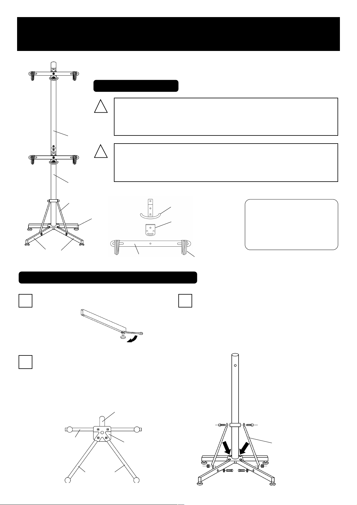
IMPORTANT NOTES
!
This stand is designed for standard two wheel bicycles.
Do not use this stand for electric bikes or tandems. The weight
limit for two bikes is 30 kgs. or 66 lbs.
Upper Pillar
!
Make sure the stand is used on a level floor.
Failing to set-up and use this stand on a level floor may cause the
stand to fall over and cause damage or injury.
Lower Pillar
Reinforcement Arm
Rear Leg
Front Leg
Alloy Stay
HOW TO ASSEMBLE YOUR PAIR STAND
Lower Support
Angle Adjust Plate
(projection is foreside)
Frame Hook
This stand requires some
assembly. You will need a M4
Hex wrench and a 13 mm
spanner in order to assemble
the PAIR STAND completely.
Screw the foot adjuster to the nut located on each leg
1
end.
Insert four M8x55 bolts into the holes on the bottom of
2
the Lower Pillar, then put through the legs. The long leg
is for rear section, and the short legs are for front section. Be sure to fit the legs to the shape of the horrow of
the bottom plate.
Lower Pillar
Rear Leg
Bottom Plate
(Fig. A)
Install the Reinforcement Arms between the Lower Pillar and
3
the Front Legs by tightening the M6x14 bolts for the pillar
side, and M6x30 bolts for the leg side. After installing the
Reinforcement Arms, tighten the M8x55 bolts firmly. Wrong
step may make you unable to install the Reinforcement Arms.
Reinforcement Arm
Front Leg
(Fig. B) (Fig.C)
Page 2
Place the Connecting Plates at the top of the Lower Pil-
4
lar. Connect the Upper Pillar to the Lower Pillar then
tighten the M6x14 bolts firmly. Now the base frame is
completed.
Lower Pillar
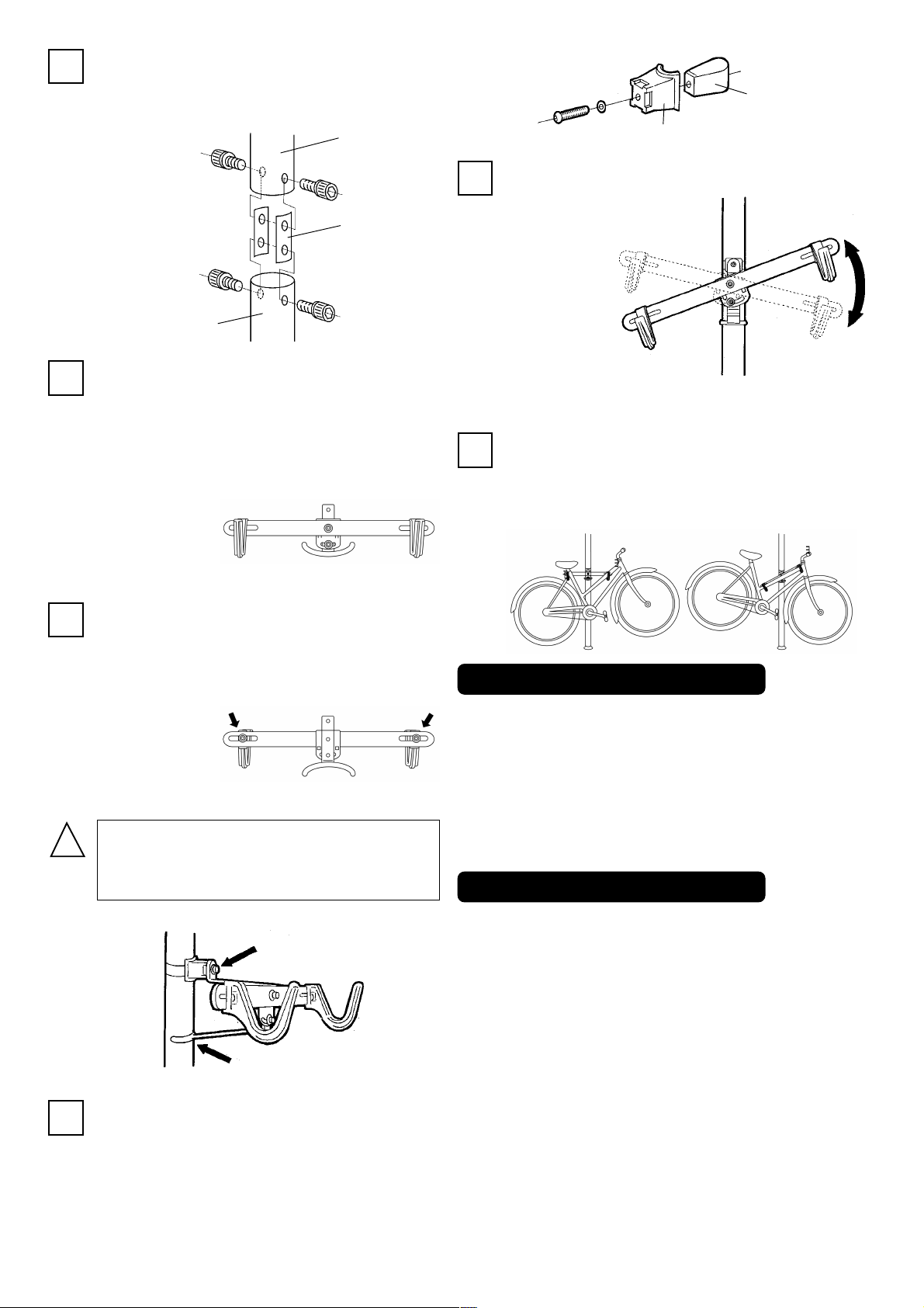
Assemble the cradles.
5
Place the Angle Adjust Plate onto the Lower Support,
then put the Alloy Stay on it. Fix three parts with the
supplied M6x20 bolt in the upper hole. (see Fig. E)
Screw the supplied M6x15 bolt in the lower hole, but
you don’t need to tighten it so firmly at this time.
Upper Pillar
Connecting
Plate
(Fig. D)
(Fig. E)
Stainless Band
Plastic Bracket
The cradle is adjustable in degrees. If you want to move
8
the cradle, loosend the lower
bolt on the angle adjust plate,
change the
angle until the
displayed bike
will be
horizontally
as much as
possible then
tighten the bolt again. (see Fig. I)
T o put a bike on PAIR ST AND, lift the bike and gently place
9
the top tube into the frame hooks.
If the bike does not have a standard frame design, it should
be supported by the top tube and rear seatstay configuration.
(see Fig. J)
O
(Fig. H)
(Fig. I)
X
The distance between the plastic frame hooks can be
6
adjusted to fit different sized bikes.
To do so, loosen the rear nut and adjust the position of
the hook. After adjusted to the required position firmly
re-tighten the nut.
(see Fig. F)
!
7
The stainless band must ONLY be used on the
upper side of the cradle. Do NOT use it on the
bottom position of the cradle. (see Fig. G)
stainless band
just putting onto the pole
Next, you'll install the bike cradles to both the upper and
lower pillars.
Disassemble the band clip first. (see Fig. H)
Wrap the stainless band around the pillar , in-sert the end
of the band between another end and the rectangle nut.
Put the plastic bracket onto the band, attach the hook or
support arm, then tighten the bolt.
(Fig. F)
(Fig. G)
(fig. J)
WHY MY NUT IS MISALIGNED?
The inside nut of the stainless band clamp is not square, it is rectanle.
You have to remove the stainless band to wind up it around the pole
for assembling. At this time, do NOT remove the nut from the band.
If you had removed the nut, make sure the nut direction that the
longer side must be vertical. If you see there is some space between
the nut and stainless band, the direction is wrong.
FOR MORE INFORMATION
For parts or service outside of Japan or North America, please consult your local shop or refer our international distributor list (found
on our web site) for the distributor in your country.
MINOURA JAPAN
1197-1 Godo, Anpachi, Gifu 503-2305 Japan
Phone: +81-(0)584-27-3131 / Fax: +81-(0)584-27-7505
Email: minoura@minoura.jp / Web: http://www.minoura.jp
MINOURA NORTH AMERICA
(for North American residents only)
1996 East Avenue, Hayward, CA 94541-5454 U.S.A.
Fax: 1-510-538-5899 / Email: MinouraUSA@ATTglobal.net
MADE IN JAPAN
Copyright 2002 Minoura Co.,Ltd. All rights reserved
 Loading...